Embed Size (px)
Citation preview
Technical Manual
Resilient Seated Butterfly Valves
CONTROLSA Division of BRAY INTERNATIONAL, Inc.
TM1050 - 08/06/2010

Resilient Seated Butterfly ValvesTechnical Manual - Table of Contents
Topic Page(s)
Introduction to Torques .................................... 3-5
Reduced Disc Diameter Bray Valves 30/31/3A .. 6
Seating & Unseating Torques ..............................7
20/21, 30/31 Imperial (Lb-Ins) ...............................8
20/21, 30/31 Metric (N-m) ....................................9
32/33, 35/36 .........................................................10
Imperial (Lb-Ins) & Metric (N-m)
22/23 Imperial (Lb-Ins) & Metric (N-m) ................11
Dynamic Torque Factors
Imperial (Lb-In/psi) ................................................12
Metric (N-m/bar) ...................................................13
Valve Sizing Coefficients .................................. 14
Imperial (Cv) .........................................................15-16
Metric (Kv) ............................................................17-18
Standard Metal Specifications
20/21 & 22/23 .......................................................19
30/31, 31H, 3A/3AH, 31U ......................................20
32/33, 35/36, 35F, 36H ..........................................21
All statements, technical information, and recommendations in this bulletin are for general use only. Consult Bray representatives or factory for the specific requirements and material selection for your intended application. The right to change or modify product design or product without prior notice is reserved.

Resilient Seated Butterfly Valves – Torques
All information herein is proprietary and confidential and may not be copied or reproduced without the expressed written consent of BRAY INTERNATIONAL, Inc.The technical data herein is for general information only. Product suitability should be based solely upon customer’s detailed knowledge and experience with their application.Introduction : 3
Torques:
INTRODUCTION
There are a number of torques which butterfly valves may experience such as:
Tsu - Seating and Unseating Torque
Td - Dynamic Torque Resulting from fluid flow
Tbf – Bearing Friction Torque
Tss – Stem Seal Friction Torque
Te – Eccentricity Torque resulting from disc offset from centerline of stem (either single, double or triple offset)
Th – Hydrostatic Torque
Factors which influence the butterfly valve torque values shown above are:
Type of Seat and Seat Material
Interference of Seat I.D. and Disc O.D.
Shaft Diameter
Valve Diameter
Bearing Coefficient of Friction
Angle of Opening
Shut-off Pressure
Fluid Velocity
Disc Shape and Configuration
Piping System and Location/Orientation of Valve in Pipe Line
System Head Characteristics
Physical Size of Disc/Shaft Obstructing Flow
Disc Edge Finish
With respect to Butterfly Valves, the two major conditions for determining total valve operating torque (TT) exists as follows:
CASE I (Angle = 0° , Disc in Closed Position) TT = Th + Tbf + Tss+ Tsu
Analyzed
Total Torque for Case I using a symmetrical disc butterfly valve is the sum of hydrostatic torque, bearing friction torque, stem seal, friction torque, and seating/unseating torque.
A. Hydrostatic Torque (Th)
We will ignore discussion of the hydrostatic torque values as they are generally insignificant compared to the seating/unseating, bearing friction and stem seal torque values (the safety factor ap-plied to seating/unseating, stem seal friction and bearing friction torque values more than compensates for the hydrostatic torque which is usually less than 2% of these total torques).
B. Bearing Friction Torque (Tbf)
Bearing friction torque occurs because pressure forces against the disc are transmitted to the stem. As the stem is forced against the bearing supports, bearing friction torque is created between the stem material and the support material as the stem is turned. Bear-ing friction torques are normally included in the seating/unseating torque values.
Bearing friction torques can be determined by using the following equation:
Tbf = .785 Cf Dv2 (d/∆P)
Where:
Tbf = Bearing Friction Torque
Cf = Coefficient of Friction (approximately .25 for non-corroded stem to cast iron body) (dimensionless).
Dv = Valve Diameter (Inches)
d = Diameter of Shaft (Inches)
∆P = Pressure Differential (psi)
C. Stem Seal Friction Torque (Tss)
For all practical purposes stem seal friction torque values are insignificant when compared to seating/unseating and bearing friction torques. Stem seal friction torques are normally included in the seating/unseating torque values.

Resilient Seated Butterfly Valves – Torques
All information herein is proprietary and confidential and may not be copied or reproduced without the expressed written consent of BRAY INTERNATIONAL, Inc.The technical data herein is for general information only. Product suitability should be based solely upon customer’s detailed knowledge and experience with their application.Introduction : 4
D. Seating/Unseating Torques (Tsu)
The seating/unseating torque value (Tsu) is a function of the pressure differential, the seat material’s coefficient of friction, the finished surface of the disc edge, the amount of interference between the seat I.D. and disc O.D. when flanged in piping, the seat thickness, and the type of service (media) for which the valve is being used. In determining the Tsu values for Bray resilient seated butterfly valves, Bray has developed Seating/Unseating Torque Charts incorporating all bearing friction and stem seal friction torques for three classes of services for both the valves with standard discs (rated to full pressure) and for valves with reduced diameter discs (rated for 50 psi [3.5 bar]). The three service classes are:
Class I – Non-Corrosive, Lubricating Service
Class II – General Service
Class III – Severe Service
Please review the guidelines for each class in the technical man-ual when determining which Seating/Unseating Torque Class should be used. Most butterfly valves are used in Class II, General Service applications.
E. Total Torque (TT)
The total torque values for Bray symmetrical disc valves for Case I applications are shown in the Seating/Unseating Torque Charts within this manual.
CASE II (Disc in Partial To Full Opening Position)
TT = Tbf + Tss+ Td
The total Torque for Case II using a symmetrical disc butterfly valve is the summation of bearing friction torque, stem seal friction torque and dynamic torque.
A. Bearing Friction Torque (Tbf)
See Case I discussion. This torque value is normally included in the Dynamic Torque Value.
B. Stem Seal Friction Torque (Tss)
See Case I discussion. This torque value is normally included in the Dynamic torque value.
C. Dynamic Torque (Td)
In a symmetrical disc design, dynamic torque occurs between the closed position, 0° and the full open position, 90°. With the disc in the partially open position, velocity of the fluid passing the lead-ing disc edge is less than the velocity passing the trailing edge. This variance in velocity past the leading disc edge and trailing disc edge results in an unbalanced distribution of pressure forces on the upstream side of the face of the disc. The total pressure forces acting perpendicular to the disc face on the leading edge half of the disc are greater than the total pressure acting perpen-dicular on the trailing half of the disc. This uneven distribution of pressure on the disc face (exists on both sides of the disc) re-sults in a torsional force which tries to turn the disc to the closed position (Figure 1). This torsional closing force can become greater than the seating/unseating torque value depending on the valve angle of opening and differential pressure.
To determine dynamic torque, the following equation is applied:
Td = Cdt d3
∆P
Where:
Td = Dynamic Torque (lbs- in).
Cdt = Coefficient of Dynamic Torque (based on disc shape and angle of opening) (dimensionless)
d = Diameter of Disc (Inches)
∆P = Pressure Differential Across Valve (psi)
FLOWMORETURBULENCEHERE
Closing Torque
Pressure Forces
Figure 1 - Pressure Distribution

Resilient Seated Butterfly Valves – Torques
All information herein is proprietary and confidential and may not be copied or reproduced without the expressed written consent of BRAY INTERNATIONAL, Inc.The technical data herein is for general information only. Product suitability should be based solely upon customer’s detailed knowledge and experience with their application.Introduction : 5
Angle of Opening 0° 10° 20° 30° 40° 50° 60° 70° 75° 80° 90°
Cdt 0 0.0126 0.0140 0.0251 0.0505 0.0809 0.1394 0.2384 0.3419 0.401 0
Figure 2 - Angle of Opening The Cdt value for Bray symmetrical disc valves are approximately:
As shown in Figure 2, dynamic torque for Bray’s symmetrical disc valves is at 0° angle of opening and increases until the angle of opening reaches 75°-80°, where it then decreases to a zero value at full open (90°) (no internal friction factors considered, just dynamic torque only).
One final comment about dynamic torque is that one may minimize the dynamic torque by the orientation of the valve (stem horizontal or vertical) in the pipeline as well as by the location (distance) in the pipeline from elbows, other valves, etc. (See Bray Resilient Seated BFV Operations and Maintenance Manual).
D. Total Torque (TT)
The total torque required for operating a Bray symmetrical disc butterfly valve at an angle opening between 0°and 90° is shown in the Dynamic Torque section of this manual. Note that the dynamic torque includes all internal friction torque values.
CONClUSIONIn most applications for butterfly valves, especially 20˝ (508mm)or smaller, the maximum torque required to operate the valve will be seating/unseating torque. However, dynamic torque should be considered particularly in:
• Control applications using larger valves (24˝ [610mm] and above) where the disc is maintained in the open position
• Applications using larger valves (24˝ [610mm] and above) where the velocity is high (16 ft./sec [5.3m/sec]).

Resilient Seated Butterfly Valves – Torques
All information herein is proprietary and confidential and may not be copied or reproduced without the expressed written consent of BRAY INTERNATIONAL, Inc.The technical data herein is for general information only. Product suitability should be based solely upon customer’s detailed knowledge and experience with their application.Introduction : 6
Reduced Disc DiameterBray Series 30/31/3A Valves
Bray offers a reduced disc diameter for 4”-20” for Series 30, 31 and 3A valves. The purpose of reducing the disc diameter is to decrease the seating/unseating torques and extend the seat life on low pressure applications.
By reducing the disc diameter, the interference between the disc O.D. and seat I.D. is decreased and the valve pressure rating, which is a function of this interference, is reduced to 50 PSI. Less interference between the disc and seat results in reduced seating/unseating torques. Lower seating/unseating torque may allow for the use ofa smaller actuator on the valve. In other applications where abrasive dry bulk materials such as cement, sugar, plastic, pallets, flour, etc., are generally pneumatically conveyed at 50 PSI or less, the reduced disc diameter not only reduces the seat-ing/unseating torque but, very importantly, usually significantly increases the services life of the seat.
Bray does the following to differentiate reduced diameter discs from full diameter discs:
Metal Discs: An “ R “ is stamped above the part number
Nylon 11 Coated Discs: Discs are differentiated by the color of the Nylon 11:
Grey – Full Disc Diameter
White – Reduced Disc Diameter
All information herein is proprietary and confidential and may not be copied or reproduced without the expressed written consent of BRAY INTERNATIONAL, Inc.The technical data herein is for general information only. Product suitability should be based solely upon customer’s detailed knowledge and experience with their application.
Resilient Seated Butterfly Valves – Seating & Unseating Torques
Torque : 7
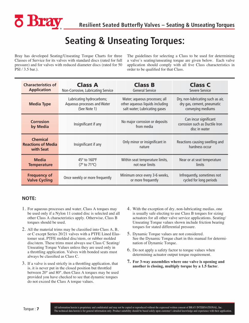
Seating & Unseating Torques:
1. For aqueous processes and water, Class A torques may be used only if a Nylon 11 coated disc is selected and all other Class A characteristics apply. Otherwise, Class B torques should be used.
2. All the material trims may be classified into Class A, B, or C except Series 20/21 valves with a PTFE Lined Elas-tomer seat, PTFE molded disc/stem, or rubber molded disc/stem. These trims must always use Class C Seating/Unseating Torque Values unless they are used only in a throttling application. Valves with bonded seats must always be classified as Class C.
3. If a valve is used strictly in a throttling application, that is, it is never put in the closed position but throttled between 20° and 80°, then Class A torques may be used provided you have checked to see that dynamic torques do not exceed the Class A torque values.
4. With the exception of dry, non-lubricating medias, one is usually safe electing to use Class B torques for sizing actuators for all other valve service applications. Seating/Unseating Torque values shown include friction bearing torques for stated differential pressure.
5. Dynamic Torque values are not considered. See the Dynamic Torque chart in this manual for determi-nation of Dynamic Torque.
6. Do not apply a safety factor to torque values when determining actuator output torque requirement.
7. For 3-way assemblies where one valve is opening and another is closing, multiply torque by a 1.5 factor.
Characteristics of Application
Class A Non-Corrosive, Lubricating Service
Class B General Service
Class C Severe Service
Media TypeLubricating hydrocarbons;
Aqueous processes and Water (See Note 1)
Water; aqueous processes; all other aqueous liquids including
salt water; Lubricating gases
Dry, non-lubricating such as air, dry gas, cement, pneumatic
conveying mediums
Corrosion by Media
Insignificant if any No major corrosion or deposits
from media
Can incur significant corrosion such as Ductile Iron
disc in water
Chemical Reactions of Media
with SeatInsignificant if any
Only minor or insignificant in nature
Reactions causing swelling and hardness occur
Media Temperature
45º to 160ºF (7º to 71ºC)
Within seat temperature limits, not near limits
Near or at seat temperature limits
Frequency of Valve Cycling
Once weekly or more frequentlyMinimum once every 3-6 weeks,
or more frequentlyInfrequently, sometimes not
cycled for long periods
Bray has developed Seating/Unseating Torque Charts for three Classes of Service for its valves with standard discs (rated for full pressure) and for valves with reduced diameter discs (rated for 50 PSI / 3.5 bar.).
The guidelines for selecting a Class to be used for determining a valve’s seating/unseating torque are given below. Each valve application should comply with all five Class characteristics in order to be qualified for that Class.
NOTE:

All information herein is proprietary and confidential and may not be copied or reproduced without the expressed written consent of BRAY INTERNATIONAL, Inc.The technical data herein is for general information only. Product suitability should be based solely upon customer’s detailed knowledge and experience with their application.
Resilient Seated Butterfly Valves – Seating & Unseating Torques
Torque : 8
Series 20/21 and 30/31 Torques (Lb-Ins)
Valve Differential Pressure (PSIG)Valve Size
Inches
Full Disc Reduced Disc
0 psi 50 psi 100 psi 150 psi 175 psi 0 psi 50 psi
Class A Non-Corrosive,
Lubricating Service
1 54 59 65 70 73 54 591.5 81 86 91 97 100 81 862 109 114 119 123 128 109 114
2.5 169 178 187 196 200 169 1783 220 236 250 264 273 220 2364 341 364 387 410 423 225 2485 510 560 610 660 687 324 3746 632 712 792 872 912 344 4888 1,182 1,341 1,500 1,660 1,741 735 89410 1,764 2,018 2,272 2,526 2,653 1,204 1,35812 2,701 3,110 3,519 3,928 4,132 1,665 2,07414 3,818 4,500 5,182 5,864 –– 2,318 3,00016 4,638 5,819 7,000 8,182 –– 2,699 3,88018 5,265 7,065 8,865 10,665 –– 2,970 4,78820 7,000 9,364 11,728 14,091 –– 3,356 6,243
Class B General Service
1 59 65 71 77 80 59 651.5 89 95 100 106 110 89 952 120 125 130 135 140 120 125
2.5 185 195 205 215 220 185 1953 245 260 275 290 297 245 2604 375 400 425 450 462 252 2675 560 615 670 725 755 355 4106 695 783 871 953 1,003 427 5378 1,300 1,475 1,650 1,825 1,915 808 98310 1,960 2,240 2,520 2,800 2,940 1,213 1,49312 2,970 3,420 3,870 4,320 4,545 1,830 2,28014 4,200 4,950 5,700 6,450 –– 2,550 3,30016 5,100 6,400 7,700 9,000 –– 2,967 4,26718 5,850 7,850 9,850 11,850 –– 3,267 5,26720 7,700 10,300 12,900 15,500 –– 4,267 6,867
Class C Severe Service
1 74 82 89 97 100 74 821.5 111 119 125 133 137 111 1192 151 157 163 169 175 151 157
2.5 231 244 257 269 275 231 2443 306 325 344 363 375 306 3254 468 500 532 563 582 316 3485 700 769 838 907 944 444 5136 870 980 1,090 1,200 1,255 525 6728 1,625 1,844 2,063 2,282 2,394 1,011 1,23010 2,450 2,800 3,150 3,500 3,675 1,517 1,86712 3,712 4,275 4,838 5,400 5,682 2,287 2,85014 5,251 6,188 7,125 8,063 –– 3,189 4,12616 6,375 8,000 9,625 11,250 –– 3,709 5,33418 7,315 9,815 12,315 14,815 –– 4,084 6,58420 9,625 12,875 16,125 19,375 –– 5,334 8,584

All information herein is proprietary and confidential and may not be copied or reproduced without the expressed written consent of BRAY INTERNATIONAL, Inc.The technical data herein is for general information only. Product suitability should be based solely upon customer’s detailed knowledge and experience with their application.
Resilient Seated Butterfly Valves – Seating & Unseating Torques
Torque : 9
Series 20/21 and 30/31 Torques (N-m)
Valve Differential Pressure (Bar)Valve Size mm
Full Disc Reduced Disc
0 bar 3.4 bar 7 bar 10.3 bar 12 bar 0 bar 3.4 bar
Class A Non-Corrosive,
Lubricating Service
25 6 7 7 8 8 6 740 9 10 10 11 11 9 1050 12 13 13 14 14 12 1365 19 20 21 22 23 19 2080 25 27 28 30 31 25 27100 39 41 44 46 48 25 28125 58 63 69 75 78 37 42150 71 80 89 99 103 39 55200 134 152 169 188 197 83 101250 199 228 257 285 300 136 153300 305 351 398 444 467 188 234350 431 508 585 663 –– 262 339400 524 657 791 924 –– 305 438450 595 798 1,002 1,205 –– 336 541500 791 1,058 1,325 1,592 –– 379 705
Class B General Service
25 7 7 8 9 9 7 740 10 11 11 12 12 10 1150 14 14 15 15 16 14 1465 21 22 23 24 25 21 2280 28 29 31 33 34 28 29100 42 45 48 51 52 28 30125 63 69 76 82 85 40 46150 79 88 98 108 113 48 61200 147 167 186 206 216 91 111250 221 253 285 316 332 137 169300 336 386 437 488 514 207 258350 475 559 644 729 –– 288 373400 576 723 870 1,017 –– 335 482450 661 887 1,113 1,339 –– 369 595500 870 1,164 1,458 1,751 –– 482 776
Class C Severe Service
25 8 9 10 11 11 8 940 13 13 14 15 15 13 1350 17 18 18 19 20 17 1865 26 28 29 30 31 26 2880 35 37 39 41 42 35 37100 53 56 60 64 66 36 39125 79 87 95 102 107 50 58150 98 111 123 136 142 59 76200 184 208 233 258 270 114 139250 277 316 356 395 415 171 211300 419 483 547 610 642 258 322350 593 699 805 911 –– 360 466400 720 904 1,087 1,271 –– 419 603450 826 1,109 1,391 1,674 –– 461 744500 1,087 1,455 1,822 2,189 –– 603 970

All information herein is proprietary and confidential and may not be copied or reproduced without the expressed written consent of BRAY INTERNATIONAL, Inc.The technical data herein is for general information only. Product suitability should be based solely upon customer’s detailed knowledge and experience with their application.
Resilient Seated Butterfly Valves – Seating & Unseating Torques
Torque : 10
Series 32/33, 35/36 Torques (Lb-Ins)Valve Size
inches
32, 35 - Max P = 75 psi 33, 36 - Max P = 150 psi
0 psi 25 psi 50 psi 75 psi 0 psi 50 psi 100 psi 150 psi
Class B General Service
(Imperial)
24 6,700 8,100 9,500 10,900 10,500 15,000 19,500 24,00026 7,900 9,800 11,700 13,600 12,400 18,400 24,400 30,40028 9,200 11,600 14,000 16,400 14,200 21,700 29,200 36,70030 10,400 13,300 16,200 19,100 16,100 25,100 34,100 43,10032 11,700 15,600 19,400 23,300 18,400 29,700 41,100 52,40034 13,500 18,500 23,500 28,500 20,950 34,750 48,600 62,40036 14,300 20,100 25,900 31,700 23,000 39,000 55,000 71,00040 18,200 26,200 34,100 42,000 24,300 46,300 68,300 90,30042 20,200 29,200 38,200 47,200 25,000 50,000 75,000 100,00044 20,800 32,500 44,200 55,800 26,700 56,700 86,700 118,30048 22,000 39,000 56,000 73,000 30,000 70,000 110,000 150,000
Class C
54 41,500 73,500 105,500 138,000 56,300 131,000 173,000 282,00060 55,500 98,200 141,000 184,800 75,100 174,500 208,000 376,00066 115,700 159,400 203,200 247,000 161,500 277,500 393,400 509,40072 Consult Factory78 Consult Factory84 Consult Factory90 Consult Factory96 Consult Factory
Series 32/33, 35/36 Torques (N-m)Valve Size mm
32, 35, - Max P = 5 bar 33, 36 - Max P = 10.3 bar
0 bar 1.7 bar 3.4 bar 5.2 bar 0 bar 3.4 bar 7 bar 10.3 bar
Class B General Service
(Metric)
600 757 915 1,074 1,232 1,187 1,695 2,204 2,712650 893 1,107 1,322 1,537 1,401 2,079 2,757 3,435700 1,040 1,311 1,582 1,853 1,605 2,452 3,300 4,147750 1,175 1,503 1,831 2,158 1,819 2,836 3,853 4,870800 1,322 1,763 2,192 2,633 2,079 3,356 4,644 5,921850 1,526 2,091 2,656 3,221 2,367 3,927 5,492 7,051900 1,616 2,271 2,927 3,582 2,599 4,407 6,215 8,023
1,000 2,057 2,961 3,853 4,746 2,746 5,232 7,718 10,2041,050 2,283 3,300 4,317 5,334 2,825 5,650 8,475 11,3001,100 2,350 3,673 4,995 6,305 3,017 6,407 9,797 13,3681,200 2,486 4,407 6,328 8,249 3,390 7,910 12,430 16,950
Class C
1,400 4,689 8,304 11,920 15,592 6,361 14,801 19,546 31,8621,500 6,271 11,095 15,931 20,880 8,485 19,716 23,501 42,4821,650 13,072 18,010 22,959 27,907 18,247 31,353 44,448 57,5551,800 Consult Factory2,000 Consult Factory2,200 Consult Factory2,250 Consult Factory2,400 Consult Factory

All information herein is proprietary and confidential and may not be copied or reproduced without the expressed written consent of BRAY INTERNATIONAL, Inc.The technical data herein is for general information only. Product suitability should be based solely upon customer’s detailed knowledge and experience with their application.
Resilient Seated Butterfly Valves – Seating & Unseating Torques
Torque : 11
Seating/Unseating TorquesBray Series 22/23 Valves
Valve Size
In. Mm.∆P = 0-150 psi ∆P = 0-10.3 bar
Lb-In N-m
2 50 288 33
2.5 65 350 40
3 80 560 63
4 100 720 81
5 125 960 108
6 150 1,300 147
8 200 2,402 271
10 250 3,840 434
12 300 5,812 657
14 350 8,000 904
16 400 11,000 1,243
18 450 15,500 1,751
20 500 19,300 2,181
24 600 30,500 3,446
1) Torques listed are for PTFE and UHMWPE trims. 2) All information based on full rated pressure differential.

Resilient Seated Butterfly Valves – Torques
All information herein is proprietary and confidential and may not be copied or reproduced without the expressed written consent of BRAY INTERNATIONAL, Inc.The technical data herein is for general information only. Product suitability should be based solely upon customer’s detailed knowledge and experience with their application.Torque : 12
Series 20/21 and 30/31(Dynamic Torque Factor - lb-in./psi) Angle of Opening 10° 20° 30° 40° 50° 60° 70° 75° 80° 90°
Valve Size
inches
2 0.113 0.126 0.225 0.453 0.726 1.251 2.139 3.068 3.052 0.000
2.5 0.216 0.240 0.430 0.865 1.386 2.388 4.085 5.858 5.827 0.000
3 0.367 0.408 0.732 1.473 2.359 4.065 6.952 9.970 9.918 0.000
4 0.855 0.949 1.702 3.425 5.486 9.454 16.168 23.187 23.065 0.000
5 1.650 1.833 3.287 6.613 10.593 18.253 31.217 44.769 44.533 0.000
6 2.494 2.771 4.969 9.997 16.014 27.594 47.192 67.680 67.323 0.000
8 6.603 6.736 12.077 24.298 38.925 67.073 114.707 164.506 163.64 0.000
10 11.990 13.322 23.885 48.056 76.985 132.653 226.862 325.353 323.640 0.000
12 20.892 23.214 41.619 83.735 134.142 231.141 395.295 566.910 563.925 0.000
14 30.039 33.377 59.841 120.396 192.873 332.342 568.366 815.119 810.828 0.000
16 45.652 50.724 90.942 182.970’ 293.115 505.070 863.764 1,238.762 1,232.240 0.000
18 65.909 73.232 131.295 264.159 423.178 729.184 1,247.040 1,788.435 1,779.020 0.000
20 91.415 101.573 182.105 366.387 586.945 1,011.373 1,729.637 2,480.549 2,467.498 0.000
Example: 4” Valve; 60° Open with a 10 PSI pressure drop: [Td = (9.454)(10) = 94.54 lb-in]
Series 32/33, 35/36 (Dynamic Torque Factor - lb-in./psi) Angle of Opening 10° 20° 30° 40° 50° 60° 70° 75° 80° 90°
Valve Size
inches
24 158.358 175.953 315.459 634.688 1,016.758 1,751.990 2,996.230 4,297.026 4,274.403 0.000
30 315.318 350.353 628.133 1,263.773 2,024.539 3,488.513 5,966.008 8,556.117 8,511.072 0.000
36 551.884 613.205 1,099.388 2,211.917 3,543.447 6,105.766 10,441.998 14,975.332 14,896.492 0.000
Larger Size Valves - Consult Factory
Example: 24” Valve; 60° Open with a 10 PSI pressure drop: [Td = (1,751.990)(10) = 17,519.90 lb-in]
Dynamic Torque Factors (Imperial)
To Use the Torque Chart, note the following:
1. Dynamic Torque values include all bearing friction and stem-seal friction torques.
2. Dynamic Torque values are per 1 PSI ∆P. To determine dynamic torque (lb-in) at a desired angle of opening, multiply the pressure drop ∆P at this angle by the appropriate dynamic torque factor in the charts below.
3. Bray recommends sizing control valves between 20° and 70°, with 60° the preferred angle.
4. Dynamic Torque will tend to close all Bray valves whose disc are symmetrical to the stem.

Resilient Seated Butterfly Valves – Torques
All information herein is proprietary and confidential and may not be copied or reproduced without the expressed written consent of BRAY INTERNATIONAL, Inc.The technical data herein is for general information only. Product suitability should be based solely upon customer’s detailed knowledge and experience with their application.Torque : 13
To Use the Torque Chart, note the following:
1. Dynamic Torque values include all bearing friction and stem-seal friction torques.
2. Dynamic Torque values are per 1 Bar ∆P. To determine dynamic torque (N-m) at a desired angle of opening, multiply the pressure drop ∆P at this angle by the appropriate dynamic torque factor in the charts below.
3. Bray recommends sizing control valves between 20° and 70°, with 60° the preferred angle.
4. Dynamic Torque will tend to close all Bray valves whose disc are symmetrical to the stem.
Series 20/21 and 30/31(Dynamic Torque Factor - N-m/bar)
Angle of Opening 10° 20° 30° 40° 50° 60° 70° 75° 80° 90°
Valve Size mm
50 0.001 0.001 0.002 0.004 0.006 0.010 0.017 0.024 0.024 0.000
65 0.002 0.002 0.003 0.007 0.011 0.019 0.032 0.046 0.045 0.000
80 0.003 0.003 0.006 0.011 0.018 0.032 0.054 0.078 0.077 0.000
100 0.007 0.007 0.013 0.027 0.043 0.074 0.126 0.181 0.180 0.000
125 0.013 0.014 0.026 0.052 0.083 0.142 0.243 0.349 0.347 0.000
150 0.019 0.022 0.039 0.078 0.125 0.215 0.368 0.528 0.525 0.000
200 0.052 0.053 0.094 0.190 0.304 0.523 0.895 1.283 1.276 0.000
250 0.094 0.104 0.186 0.375 0.600 1.035 1.770 2.538 2.524 0.000
300 0.163 0.181 0.325 0.653 1.046 1.803 3.083 4.422 4.399 0.000
350 0.234 0.260 0.467 0.939 1.504 2.592 4.433 6.358 6.324 0.000
400 0.356 0.396 0.709 1.427 2.286 3.940 6.737 9.662 9.611 0.000
450 0.514 0.571 1.024 2.060 3.301 5.688 9.727 13.950 13.876 0.000
500 0.713 0.792 1.420 2.858 4.578 7.889 13.491 19.340 19.246 0.000
Example: 100 mm Valve; 60° Open with a 10 Bar pressure drop: [Td = (.074)(10) = .74 N-m]
Series 32/33, 35/36 (Dynamic Torque Factor - N-m/bar)
Angle of Opening 10° 20° 30° 40° 50° 60° 70° 75° 80° 90°
Valve Size mm
600 1.235 1.372 2.461 4.951 7.931 13.666 23.371 33.517 33.340 0.000
750 2.459 2.733 4.899 9.857 15.791 27.210 46.535 66.738 66.386 0.000
900 4.305 4.783 8.575 17.253 27.639 47.625 81.448 116.808 116.193 0.000
Larger Size Valves - Consult Factory
Example: 600 mm Valve; 60° Open with a 10 Bar pressure drop: [Td = (13.666)(10) = 136.66 N-m]
Dynamic Torque Factors (Metric)

Resilient Seated Butterfly Valves – Valve Sizing Coefficients
All information herein is proprietary and confidential and may not be copied or reproduced without the expressed written consent of BRAY INTERNATIONAL, Inc.The technical data herein is for general information only. Product suitability should be based solely upon customer’s detailed knowledge and experience with their application.Coefficients : 14
Valve Sizing Coefficients:1. Valve Sizing Coefficients (Cv) . . . . . . . . . . . . . . . . . . . . . . . . . . . . . . . . . . . Pages 14-15
1. Cv stands for Valve Sizing Coefficient, sometimes called the Flow Rate Coefficient.2. Cv varies with the valve size, angle of opening and the manufacturer’s valve style.3. Cv is defined as the volume of water in USGPM that will flow through a given restriction or valve
opening with a pressure drop of one (1) psi at room temperature.
2. Valve Sizing Coefficients (Kv) . . . . . . . . . . . . . . . . . . . . . . . . . . . . . . . . . . . Pages 16-17
1. Kv stands for Valve Sizing Coefficient, sometimes called the Flow Rate Coefficient.2. Kv varies with the valve size, angle of opening and the manufacturer’s valve style.3. Kv is defined as the volume of water in Cubic Meters/Hour (m3/hr) that will flow through a given
restriction or valve opening with a pressure drop of one (1) bar at room temperature.

Resilient Seated Butterfly Valves – Valve Sizing Coefficients
All information herein is proprietary and confidential and may not be copied or reproduced without the expressed written consent of BRAY INTERNATIONAL, Inc.The technical data herein is for general information only. Product suitability should be based solely upon customer’s detailed knowledge and experience with their application.Coefficients : 15
Series 20/21 - Valve Sizing Coefficient (Cv) Valve Size
inches
Disc Position (Degrees)
10º 20º 30º 40º 50º 60º 70º 80º 90º1 0.1 1 3 6 11 21 36 56 61
1.5 0.2 2 6 11 26 50 87 129 147
2 0.9 7 16 27 45 73 123 172 244
2.5 1 11 25 43 71 115 201 310 439
3 2 16 35 62 102 165 290 488 691
4 4 28 63 110 182 294 515 906 1,282
5 6 44 98 172 284 459 805 1,416 2,070
6 7 59 130 227 376 607 1,065 1,873 2,786
8 13 106 244 427 714 1,147 1,935 3,402 5,191
10 21 168 387 675 1,130 1,815 3,062 5,385 8,238
12 31 245 562 981 1,642 2,636 4,448 7,820 12,102
14 40 307 706 1,234 2,064 3,313 5,590 9,829 15,210
16 52 403 925 1,617 2,706 4,343 7,328 12,885 19,940
18 68 528 1,213 2,121 3,549 5,695 9,610 16,898 26,150
20 85 660 1,517 2,651 4,436 7,120 12,014 21,124 32,690
Series 22/23 - Valve Sizing Coefficient (Cv) Valve Size
inches
Disc Position (Degrees)
10º 20º 30º 40º 50º 60º 70º 80º 90º2 1 7 16 27 44 62 85 115 146
2.5 1 11 24 43 69 110 176 235 300
3 2 15 35 61 98 158 286 413 586
4 3 27 62 109 177 285 503 812 1,051
5 5 43 98 171 276 440 798 1,297 1,814
6 6 57 129 226 364 580 1,048 1,737 2,576
8 12 104 242 424 698 1,111 1,908 3,142 4,354
10 20 165 385 672 1,105 1,761 3,004 4,976 6,834
12 29 241 559 975 1,604 2,591 4,420 7,392 10,090
14 35 300 720 1,280 2,100 3,300 5,700 9,350 12,880
16 45 350 850 1,650 2,750 4,400 7,500 12,320 16,900
18 55 510 1,200 2,100 3,600 5,700 9,830 15,600 21,600
20 80 650 1,550 2,700 4,480 7,100 12,200 19,900 27,500
24 180 1,000 2,450 4,600 7,000 11,300 18,900 28,500 34,800

Resilient Seated Butterfly Valves – Valve Sizing Coefficients
All information herein is proprietary and confidential and may not be copied or reproduced without the expressed written consent of BRAY INTERNATIONAL, Inc.The technical data herein is for general information only. Product suitability should be based solely upon customer’s detailed knowledge and experience with their application.Coefficients : 16
Series 30/31/31H/3A/3AH/31U - Valve Sizing Coefficient (Cv) Valve Size
Inches
Disc Position (Degrees)
10º 20º 30º 40º 50º 60º 70º 80º 90º2 0.8 7 16 27 43 61 84 114 144
2.5 1 11 24 43 67 107 163 223 282
3 2 15 35 61 96 154 267 364 461
4 3 27 62 109 171 274 496 701 841
5 5 43 98 170 268 428 775 1,146 1,376
6 6 56 129 225 354 567 1,025 1,542 1,850
8 12 102 241 421 680 1,081 1,862 2,842 3,316
10 19 162 382 667 1,076 1,710 2,948 4,525 5,430
12 27 235 555 1,005 1,594 2,563 4,393 6,731 8,077
14 34 299 756 1,320 2,149 3,384 5,939 8,874 10,538
16 45 397 1,001 1,749 2,847 4,483 7,867 11,761 13,966
18 58 507 1,281 2,237 3,643 5,736 10,065 14,496 17,214
20 72 632 1,595 2,786 4,536 7,144 12,535 18,812 22,339
Series 32/33/35/36/35F/36H - Valve Sizing Coefficient (Cv) Valve Size
Inches
Disc Position (Degrees)
10º 20º 30º 40º 50º 60º 70º 80º 90º22 103 916 2,070 3,510 5,640 43,800 14,562 22,028 27,168
24 259 1,028 2,387 4,244 6,962 50,700 18,235 27,186 33,154
26 289 1,141 2,752 4,890 7,824 61,000 19,921 29,700 36,220
28 295 1,324 3,133 5,399 8,636 70,200 22,578 34,683 41,619
30 420 1,652 3,986 7,080 11,328 43,800 28,844 43,003 52,443
32 550 2,026 4,636 7,983 12,743 50,700 32,591 48,558 60,658
34 533 2,304 5,210 8,834 14,194 61,000 36,648 55,438 68,374
36 740 2,775 5,936 9,790 15,572 70,200 40,086 59,667 77,089
40 757 2,971 6,925 11,862 19,307 43,800 50,406 73,990 90,175
42 783 3,502 7,879 12,997 21,010 50,700 54,584 83,421 102,989
44 904 4,066 8,698 14,346 22,818 61,000 58,740 87,430 112,960
48 1,023 4,651 10,365 17,010 27,242 70,200 70,431 108,968 132,888
52 Consult Factory54 1,299 5,904 13,158 21,594 34,583 55,671 89,411 138,334 168,700
60 1,480 6,400 14,500 24,500 39,400 63,200 102,000 154,000 190,000
66 1,650 7,110 16,100 27,300 43,800 70,200 113,000 171,000 211,000
72 1,900 8,220 18,600 31,500 50,700 81,200 131,000 198,000 244,000
78 2,290 9,910 22,400 38,000 61,000 97,800 158,000 238,000 294,000
84 2,290 11,390 25,800 43,700 70,200 112,400 181,000 274,000 338,000
90 Consult Factory96 Consult Factory

Resilient Seated Butterfly Valves – Valve Sizing Coefficients
All information herein is proprietary and confidential and may not be copied or reproduced without the expressed written consent of BRAY INTERNATIONAL, Inc.The technical data herein is for general information only. Product suitability should be based solely upon customer’s detailed knowledge and experience with their application.Coefficients : 17
Series 20/21 - Valve Sizing Coefficient (Kv) Valve Size mm
Disc Position (Degrees)
10º 20º 30º 40º 50º 60º 70º 80º 90º25 0.009 0.085 0.256 0.512 0.938 1.791 3.071 4.777 5.203
40 0.017 0.171 0.512 0.938 2.218 4.265 7.421 11.004 12.539
50 0.077 0.597 1.365 2.303 3.839 6.227 10.492 14.672 20.813
65 0.085 0.938 2.133 3.668 6.056 9.810 17.145 26.443 37.447
80 0.171 1.365 2.986 5.289 8.701 14.075 24.737 41.626 58.942
100 0.341 2.388 5.374 9.383 15.525 25.078 43.930 77.282 109.355
125 0.512 3.753 8.359 14.672 24.225 39.153 68.667 120.785 176.571
150 0.597 5.033 11.089 19.363 32.073 51.777 90.845 159.767 237.646
200 1.109 9.042 20.813 36.423 60.904 97.839 165.056 290.191 442.792
250 1.791 14.330 33.011 57.578 96.389 154.820 261.189 459.341 702.701
300 2.644 20.899 47.939 83.679 140.063 224.851 379.414 667.046 1,032.301
350 3.412 26.187 60.222 105.260 176.059 282.599 476.827 838.414 1,297.413
400 4.436 34.376 78.903 137.930 230.822 370.458 625.078 1,099.091 1,700.882
450 5.800 45.038 103.469 180.921 302.730 485.784 819.733 1,441.399 2,230.595
500 7.251 56.298 129.400 226.130 378.391 607.336 1,024.794 1,801.877 2,788.457
Series 22/23 - Valve Sizing Coefficient (Kv) Valve Size mm
Disc Position (Degrees)
10º 20º 30º 40º 50º 60º 70º 80º 90º50 0.085 0.597 1.365 2.303 3.753 5.289 7.251 9.810 12.454
65 0.085 0.938 2.047 3.668 5.886 9.383 15.013 20.046 25.590
80 0.171 1.280 2.986 5.203 8.359 13.477 24.396 35.229 49.986
100 0.256 2.303 5.289 9.298 15.098 24.311 42.906 69.264 89.650
125 0.427 3.668 8.359 14.586 23.543 37.532 68.069 110.634 154.734
150 0.512 4.862 11.004 19.278 31.049 49.474 89.394 148.166 219.733
200 1.024 8.871 20.643 36.167 59.539 94.768 162.752 268.013 371.396
250 1.706 14.075 32.841 57.322 94.257 150.213 256.241 424.453 582.940
300 2.474 20.557 47.683 83.168 136.821 221.012 377.026 630.538 860.677
350 2.986 25.590 61.416 109.184 179.130 281.490 486.210 797.555 1,098.664
400 3.839 29.855 72.505 140.745 234.575 375.320 639.750 1,050.896 1,441.570
450 4.692 43.503 102.360 179.130 307.080 486.210 838.499 1,330.680 1,842.480
500 6.824 55.445 132.215 230.310 382.144 605.630 1,040.660 1,697.470 2,345.750
600 15.354 85.300 208.985 392.380 597.100 963.890 1,612.170 2,431.050 2,968.440

Resilient Seated Butterfly Valves – Valve Sizing Coefficients
All information herein is proprietary and confidential and may not be copied or reproduced without the expressed written consent of BRAY INTERNATIONAL, Inc.The technical data herein is for general information only. Product suitability should be based solely upon customer’s detailed knowledge and experience with their application.Coefficients : 18
Series 30/31/31H/3A/3AH/31U - Valve Sizing Coefficient (Kv) Valve Size mm
Disc Position (Degrees)
10º 20º 30º 40º 50º 60º 70º 80º 90º50 0.068 0.597 1.365 2.303 3.668 5.203 7.165 9.724 12.283
65 0.085 0.938 2.047 3.668 5.715 9.127 13.904 19.022 24.055
80 0.171 1.280 2.986 5.203 8.189 13.136 22.775 31.049 39.323
100 0.256 2.303 5.289 9.298 14.586 23.372 42.309 59.795 71.737
125 0.427 3.668 8.359 14.501 22.860 36.508 66.108 97.754 117.373
150 0.512 4.777 11.004 19.193 30.196 48.365 87.433 131.533 157.805
200 1.024 8.701 20.557 35.911 58.004 92.209 158.829 242.423 282.855
250 1.621 13.819 32.585 56.895 91.783 145.863 251.464 385.983 463.179
300 2.303 20.046 47.342 85.727 135.968 218.624 374.723 574.154 688.968
350 2.900 25.505 64.487 112.596 183.310 288.655 506.597 756.952 898.891
400 3.839 33.864 85.385 149.190 242.849 382.400 671.055 1,003.213 1,191.300
450 4.947 43.247 109.269 190.816 310.748 489.281 858.545 1,236.509 1,468.354
500 6.142 53.910 136.054 237.646 386.921 609.383 1,069.236 1,604.664 1,905.517
Series 32/33/35/36/35F/36H - Valve Sizing Coefficient (Kv) Valve Size mm
Disc Position (Degrees)
10º 20º 30º 40º 50º 60º 70º 80º 90º550 8.786 78.135 176.571 299.403 481.092 3,736.140 1,242.139 1,878.988 2,317.430
600 22.093 87.688 203.611 362.013 593.859 4,324.710 1,555.446 2,318.966 2,828.036
650 24.652 97.327 234.746 417.117 667.387 5,203.300 1,699.261 2,533.410 3,089.566
700 25.164 112.937 267.245 460.535 736.651 5,988.060 1,925.903 2,958.460 3,550.101
750 35.826 140.916 340.006 603.924 966.278 3,736.140 2,460.393 3,668.156 4,473.388
800 46.915 172.818 395.451 680.950 1,086.978 4,324.710 2,780.012 4,141.997 5,174.127
850 45.465 196.531 444.413 753.540 1,210.748 5,203.300 3,126.074 4,728.861 5,832.302
900 63.122 236.708 506.341 835.087 1,328.292 5,988.060 3,419.336 5,089.595 6,575.692
1,000 64.572 253.426 590.703 1,011.829 1,646.887 3,736.140 4,299.632 6,311.347 7,691.928
1,050 66.790 298.721 672.079 1,108.644 1,792.153 4,324.710 4,656.015 7,115.811 8,784.962
1,100 77.111 346.830 741.939 1,223.714 1,946.375 5,203.300 5,010.522 7,457.779 9,635.488
1,200 87.262 396.730 884.135 1,450.953 2,323.743 5,988.060 6,007.764 9,294.970 11,335.346
1,300 Consult Factory
1,400 110.805 503.611 1,122.377 1,841.968 2,949.930 4,748.736 7,626.758 11,799.890 14,390.110
1,500 126.244 545.920 1,236.850 2,089.850 3,360.820 5,390.960 8,700.600 13,136.200 16,207.000
1,650 140.745 606.483 1,373.330 2,328.690 3,736.140 5,988.060 9,638.900 14,586.300 17,998.300
1,800 162.070 701.166 1,586.580 2,686.950 4,324.710 6,926.360 11,174.300 16,889.400 20,813.200
2,000 195.337 845.323 1,910.720 3,241.400 5,203.300 8,342.340 13,477.400 20,301.400 25,078.200
2,200 195.337 971.567 2,200.740 3,727.610 5,988.060 9,587.720 15,439.300 23,372.200 28,831.400
2,250 Consult Factory
2,400 Consult Factory

Resilient Seated Butterfly Valves – Standard Metal Specifications
All information herein is proprietary and confidential and may not be copied or reproduced without the expressed written consent of BRAY INTERNATIONAL, Inc.The technical data herein is for general information only. Product suitability should be based solely upon customer’s detailed knowledge and experience with their application.Metal Specs : 19
Series 20/21 - Standard Metal Specifications
Part Material ASTM No. UNS No.
Body
Cast Iron A126 Class B
Ductile Iron A395 Gr. 60-40-18 F32800
316 Stainless Steel A351 CF8M J92900
Aluminum B26 Class B
Disc/Stem 1-12”(25-300mm) One Piece
316 Stainless Steel A351 CF8M J92900
Hastelloy® C22 * B494 CX2MW N26022
17-4 ph Stainless Steel A747 CB7Cu1 Heat Treated J92180
Disc/Stem 14-20”
(350-500mm) Fabricated
Disc316 Stainless Steel A240 S31600
Hastelloy® C276 * B575 N10276
17-4 ph Stainless Steel A564 630 Heat Treated S17400
Stem316 Stainless Steel A276 S31600
Hastelloy® C276 * B575 N10276
17-4 ph Stainless Steel A564 630 Heat Treated S17400
Series 22/23 - Standard Metal SpecificationsPart Material ASTM No. UNS No.
BodyDuctile Iron A395 Gr. 60-40-18 F32800
316 Stainless Steel A351 CF8M J92900
Carbon Steel A216 WCB J030002
Disc
316 Stainless Steel A351 CF8M J92900
PTFE/316 SS (2”-12”) A351 CF8M J92900
PTFE/17-4 ph SS (14”-24”) A547 CB7Cu1 J92180
UHMWPE/316 SS (2”-6”) A351 CF8M J92900
UHMWPE/DI (8”-12”) A536 Gr 65-45-12 F33100
Hastelloy® C22 * B494 CX2MW N26022
Titanium
Stem 17-4 ph Stainless Steel A564 630 Heat Treated S17400
* Hastelloy® is a registered trademark of Haynes International, Inc.

Resilient Seated Butterfly Valves – Standard Metal Specifications
All information herein is proprietary and confidential and may not be copied or reproduced without the expressed written consent of BRAY INTERNATIONAL, Inc.The technical data herein is for general information only. Product suitability should be based solely upon customer’s detailed knowledge and experience with their application.Metal Specs : 20
Series 30/31, 31H, 3A/3AH, 31U - Standard Metal Specifications
Part Material ASTM No.UNS No.
30/31 31H 3A/3AH 31U
Body
Cast Iron A126 Class B • • •Ductile Iron A536 Gr. 65-45-12 F33100 • • •Ductile Iron A395 F32800 •Carbon Steel A216 WCB J030002 • • •Nickel Aluminum Bronze B-148 C95800 •Aluminum B26 Class B •
Disc
Aluminum Bronze B148 C95400 • • •Nickel Aluminum Bronze B148 C95800 •Nylon Coated Ductile Iron A536 Gr. 65-45-12 F33100 • • •316 Stainless Steel A351 CF8M J92900 • • • •304 Stainless Steel A351 CF8 J92600 • •Duplex Stainless Steel A995 Gr 5A J93404 • •Super Austenitic Stainless Steel (254 SMO™)*
A351 Grade CK3MCuN S31254 • •
Hastelloy® C-276 * B575 N10276 • •
Stem
304 Stainless Steel A276 S30400 • •316 Stainless Steel A276 S31600 • •416 Stainless Steel A582 S41600 • • • •17-4 ph Stainless Steel A564 630 Heat Treated S17400 •Monel® * B865 N05500 • • •
* Hastelloy® is a registered trademark of Haynes International, Inc. Monel® is a registered trademark of International Nickel Company, Inc. 254 SMO™ is a registered trademark of Avesta AB. AL-6XN® is a registered trademark of ATI Properties, Inc.

Resilient Seated Butterfly Valves – Standard Metal Specifications
All information herein is proprietary and confidential and may not be copied or reproduced without the expressed written consent of BRAY INTERNATIONAL, Inc.The technical data herein is for general information only. Product suitability should be based solely upon customer’s detailed knowledge and experience with their application.Metal Specs : 21
Series 32/33, 35/36, 35F, 36H - Standard Metal Specifications
Part Material ASTM No.UNS No.
32-36 36H 35F
Body
Cast Iron A126 Class B • •Ductile Iron A536 Gr. 65-45-12 F33100 • • •Carbon Steel A216 Gr. WCB J030002 •316 Stainless Steel A351 CF8M J92900 •
Disc
Nickel Aluminum Bronze B148 C95800 • •Nylon Coated Ductile Iron A536 Gr. 65-45-12 F33100 • •316 Stainless Steel A351 CF8M J92900 •304 Stainless Steel A351 CF8 J92600 •Hastelloy® C-276 * B575 N10276 CF •Hastelloy® C-22 * B494 CX2MW N26022 CF
Duplex Stainless Steel A995 Gr 5A J93404 • • •Super Austenitic Stainless Steel (254 SMO ™) *
A351 Grade CK3MCuN S31254 • • •
Monel® * A494 Grade M-35-1 N24135 •
Stem
304 Stainless Steel A276 S30400 • •316 Stainless Steel A276 S31600 • •416 Stainless Steel A582 S41600 •17-4 ph Stainless Steel A564 630 Heat Treated S17400 • •Duplex Stainless Steel A479 S31651 •Super Austenitic Stainless Steel (AL-6XN®) * A276 N08367 • •Monel® * B865 N05500 •
* Hastelloy® is a registered trademark of Haynes International, Inc. Monel® is a registered trademark of International Nickel Company, Inc. 254 SMO™ is a registered trademark of Avesta AB. AL-6XN® is a registered trademark of ATI Properties, Inc.