Embed Size (px)
Citation preview

1
NCT®201 Controls for Lathes
Operator’s Manual Alpha version of SW as of 24/09/2012

2
READ THIS MANUAL BEFORE USING THIS PRODUCT. FAILURE TO FOLLOW THE INSTRUCTIONS AND SAFETY PRECAUTIONS IN THIS MANUAL CAN RESULT IN SERIOUS INJURY All operators and service personnel must read this manual before operating the NCT CNC control equipment and all connected machine tools. Keep this manual in a safe location for future reference. Information provided by NCT relating to wiring, installation, and operation of CNC components is intended as only a guide, and in all cases a qualified technician and all applicable local codes and laws must be consulted. NCT makes no claims about the completeness or accuracy of the information provided, as it may apply to an infinite number of field conditions. As CNC control products from NCT can be installed on a wide variety of machine tools NOT sold or supported by NCT, you MUST consult and follow all safety instructions provided by your machine tool manufacturer regarding the safe operation of your machine and unique application. © Copyright NCT 2013.01.31 The Publisher reserves all rights for the contents of this manual. No reprinting, even in extracts, is permissible unless our written consent is obtained. The text of this manual has been compiled and checked with utmost care, yet we assume no liability for possible errors or spurious data and for consequential losses or damages. If you cannot find an evident answer to your questions in this manual, we kindly ask you to contact our experts, so that we can assist you.

3
CONTENTS 1. Introduction .......................................................................................................................... 6
2. General Operating Information .......................................................................................... 7 Touch screen .......................................................................................................................... 7
2.1 Softkey ............................................................................................................................. 7
2.2 Side Bar ............................................................................................................................ 8
2.2.1. WIN-S Button .......................................................................................................... 9
2.2.2. Keypad ................................................................................................................... 10
2.2.3. Software Machine Operation Panel ........................................................................ 11
2.2.3.1. Operating Modes ............................................................................................. 11
2.2.3.2. Increment Selectors ......................................................................................... 11
2.2.3.2. Feed Rate Override Switch ............................................................................. 11
2.2.3.4. Spindle Speed Override ................................................................................... 12
2.2.3.5. Program Execution Buttons ............................................................................ 12
2.2.3.6. Start, stop and movement buttons ................................................................... 12
2.3. User Box ........................................................................................................................ 14
2.3.1. Creating a New User Box ....................................................................................... 14
2.3.2. Setup of Password .................................................................................................. 14
2.3.3. Modifying Your Password ..................................................................................... 15
2.3.4. Cancelling Your Password ..................................................................................... 15
2.3.5. Log out from the User Box .................................................................................... 15
2.3.6. Authorization Levels .............................................................................................. 15
3. Operation Modes ................................................................................................................ 17 3.1. Jog Operation Mode ...................................................................................................... 17
3.2. Incremental Jog Operation Mode .................................................................................. 18
3.3 Handwheel Operation Mode .......................................................................................... 19
3.3.1. Multiple Hand wheels ............................................................................................ 20
3.4. Reference Point Return Operation Mode ...................................................................... 20
3.5. Automatic Operation Mode ........................................................................................... 21
3.6. Manual Data Input (MDI) ............................................................................................. 21
3.6.1. Differences between Automatic and MDI Mode ................................................... 21
3.7. Edit Operation Mode ..................................................................................................... 22
3.8. Turn Off the Control and Restart .................................................................................. 22
4. Position Display .................................................................................................................. 23 4.1. Handling the Position Window ..................................................................................... 25
5. Status ................................................................................................................................... 26 5.1 Program Blocks during Automatic Execution ............................................................... 26
5.1.1. Program List Functions .......................................................................................... 26
5.2. Graphic Display of the Tool Path .................................................................................. 29
5.2.1. Setting of the graphic display ................................................................................. 29
5.2.1.1. Zoom ............................................................................................................... 29
5.2.1.2. Moving ............................................................................................................ 30
5.2.1.3. Rotation ........................................................................................................... 30
5.2.1.4. Setting of the drawing ..................................................................................... 30
5.3. Macro Variables ............................................................................................................ 32
5.3.1. Local macro variables #1- #33 ............................................................................... 32
5.3.2. Global macro variables #100- #499 and #500- #999 ............................................ 32
5.3.3. Editing of the Macro Table .................................................................................... 33
5.3.4. Validation of Changes ............................................................................................ 34

4
5.3.5. The important Variables in one place .................................................................... 34
5.4. Messages ....................................................................................................................... 35
5.4.1. Construction of message numbers .......................................................................... 36
5.4.2. Groups of Messages ............................................................................................... 36
5.5 Backup Copy .................................................................................................................. 38
5.6 Logbook ......................................................................................................................... 39
5.6.1. Filtering the Messages ............................................................................................ 40
5.7. Parameters ..................................................................................................................... 41
5.8. Status Display ................................................................................................................ 42
5.9. Part and Time Counter .................................................................................................. 44
6. Program ............................................................................................................................... 45 6.1. Single block ................................................................................................................... 45
6.2. CNC Program ................................................................................................................ 46
6.2.1. Creating a new CNC program ................................................................................ 46
6.2.2. Editing an existing CNC program .......................................................................... 46
6.2.3. Helping Functions by Editing ................................................................................ 47
6.2.4. Program Execution in Automatic operation mode ................................................. 48
7. Offsets .................................................................................................................................. 49 7.1. 0-points (Work shift) ..................................................................................................... 49
7.1.1 Work Offset ................................................................................................................ 49
7.1.2. Work Offset Measure (CNC lathe) ........................................................................ 49
7.1.3. Editing the Work Offset Table ............................................................................... 50
7.1.4. Selection of work zero point in a program ............................................................. 51
7.2. Tool Offsets ................................................................................................................... 51
7.2.1. Tool offset measuring (on the CNC lathe) ............................................................. 52
7.2.2. Editing the Tool Offset Table ................................................................................. 55
7.3. Orientation and Offset of the main spindle ................................................................... 57
7.3.1. Setting the orientation position .............................................................................. 57
7.3.2. Driving Spindles in Shifted Phase Mode (part transfer between spindles) ............ 58
7.3.2.1. Calculation of Phase Offset ............................................................................. 58
8. Program Execution Start and Stop ................................................................................... 59 8.3. Reset .............................................................................................................................. 60
8.4. Programmed Stop M00 ................................................................................................. 61
8.5. Optional Stop M01 ........................................................................................................ 61
8.6. End of Program: M02, M30 .......................................................................................... 61
9. Program Execution Intervention .................................................................................. 62
9.1. Conditional Block Skip ................................................................................................. 62
9.2. Increasing the Feed rate Using Rapid Traverse Jog Button .......................................... 62
10. Debugging the Part Program ...................................................................................... 63
10.1. Single Block Execution ............................................................................................... 63
10.2. Dry Run (all feed rates at high speed) ........................................................................ 63
10.3. Machine Lock Function .............................................................................................. 63
10.4. Function Lock ............................................................................................................. 64
10.5. Axis Lock .................................................................................................................... 64
10.6. Test Run ...................................................................................................................... 64
10.7. Calculation of Cutting Speed ...................................................................................... 65
10.7.1. Constant cutting speed calculation (G96, G97).................................................... 65
10.8. Description of G and M codes ..................................................................................... 66
11. Interrupting and Restarting the Automatic Operation ................................................ 68
11.1. Interrupting the Automatic Operation ......................................................................... 68

5
11.2. Restarting the Automatic Operation ............................................................................ 68
11.3. Unconditional Restart the Automatic Operation ......................................................... 69
11.3.1. Interrupting Simple Movements ........................................................................... 69
11.3.2. Interrupting the Drilling Cycles ........................................................................... 70
11.3.3. Interrupting the Machining in Tool Radius Compensation Mode ....................... 72
11.4. Automatic Operation Restart with BLOCK RESTART Condition ............................ 73
11.4.1. Return to the start position of the block with manual operation .......................... 74
11.4.3. Different return moves while the BLOCK RESTART is active. ......................... 75
11.5. Automatic Mode Restart with BLOCK RETURN turned on ..................................... 78
11.6. Automatic Operation Start after Block Search ............................................................ 78
11.6.1. Pointing at the Desired Block ............................................................................... 79
11.6.2. Pointing at the Desired Block in a sub-program .................................................. 79
11.6.3. The SEARCH Command ..................................................................................... 79
11.6.4. The GOTO Command .......................................................................................... 86
11.6.5. Giving a Repetition Number ................................................................................ 86
12. Settings .............................................................................................................................. 87 12.1. The Sound of KEY CLICKS ....................................................................................... 87
12.1.1. KEY CLICK Sounds of the Operating System .................................................... 87
12.1.2. KEY CLICK Sounds from the CNC system. ....................................................... 87
12.2. Program settings .......................................................................................................... 88
12.2.1. Style adjustment ................................................................................................. 88
12.2.2. The Sound of Error Messages .............................................................................. 89
12.2.3. The Language of the USB keyboard .................................................................... 90
12.2.4. Which keyboard is active? ................................................................................... 90
12.2.5. Freezing the windows ........................................................................................... 92
12.2.6. Setting the Help Text ............................................................................................ 94
12.2.7. Calibration of the Touch screen ........................................................................... 95
12.2.8. Setting the Resolution of the Screen .................................................................... 96
12.2.9. Setting the time and date ...................................................................................... 97
13. Channels ..................................................................................................................... 98
13.1. Handling of the Windows ........................................................................................... 98
13.2. Position display of channels ........................................................................................ 98
13.3. The START button ...................................................................................................... 99
13.4. STOP button ................................................................................................................ 99
13.5. Multi-channel Program Execution in Automatic Operation Mode ............................. 99
13.6. Operation Mode Change ........................................................................................... 100

6
1. Introduction Dear User, Thank you for having chosen one of our control systems. We sincerely hope that you will be satisfied in your work with its facilities. Please remember that the skill of operating the machine can only be learned through knowing its part programming fundamentals. Similarly, no programming is possible unless the skills of machine operation are acquired.
THE MACHINE CANNOT BE MANIPULATED OR OPERATED SAFELY UNLESS YOU CAN INTERPRET THE PART PROGRAM AND CHECK IT FOR CORRECTNESS! THE OPERATOR OF THE
MACHINE MUST ALWAYS FORESEE ALL POSSIBLE CONSEQUENCES OF THEIR ACTIONS!
Conditions of Operation and Storage The control system may be operated at an ambient temperature between +10°C (14°F) and +40°C. (104°F) In case the environment temperature increases above +40 C, the control must be turned off. The temperature range for storage is –10 C to +60 C. (140°F) in the electric cabinet, a slight over-pressure must be secured by means of a fan with filter, mounted on the cabinet. Cleaning and (if needed) replacement of the ventilator filter is necessary for the proper operation of the control system.

7
2. General Operating Information
Touch screen NCT201 control units have touch screens. You can push the buttons on the screen either with your fingers or by using the stylus provided. You can use a keyboard and mouse set up via any of the four USB ports provided. The operating surface is similar to the Windows OS. You are free to change the size of any window by clicking on the resize icon visible below.
You may close the window by clicking the red X, as shown below.
If the content inside the windowed box is not completely visible, the scroll bars on the side and bottom can be used to show all the content. In the control unit there are two important menu systems: - The Side Bar, which can be placed on either the right or left side of the screen. - The SOFTKEY menu, which is displayed on the bottom of the screen. The basic status of the SOFTKEY menu is shown below.
2.1 Softkey The SOFTKEY menu system provides access to all of the functions of the control unit. You can operate it directly by touching the screen. (We will us the SK abbreviation in the following text, if we describe a command line)

8
2.2 Side Bar Below are all of the side bar buttons and their functions.
This allows you to move the side bar from one side to another. This is the WIN-S button, which opens another group of windows and functions. This is the PLC button, which allows you to switch the PLC functions on and off. This is the software mechanical panel, which controls the machine functions. This is the keypad button, which brings up the onscreen keyboard. This allows you to turn the auto pop-up of the keyboard on and off. The dock buttons allows you to place any windows on the screen next to each other without any gaps or overlapping between them.
9
2.2.1. WIN-S Button
The WIN-S button brings up a sub menu which contains the following 24 functions. 1. Mechanical position 2. List of G and M codes 3. Information about main spindle and tools (F, S, T) 4. Single block 5. Directory 1 (for files) 6. Directory 2 (for files) 7. Listing of activated programs 8. Graphics 9. Work zero point offset measure 10. Work zero point offsets 11. Tool correction table (mill) 12. Tool correction table (lathe) 13. Tool handling table 14. Local macros #1-#33 15. Global macros #100-#499 16. Global macros #500-#999 17. Part and time counter 18. Running applications 19. Calculator 20. Keyboard 21. Revolutions of the spindle 22. Calculation of cutting speed 23. DXF converter 24. Setup
10
2.2.2. Keypad
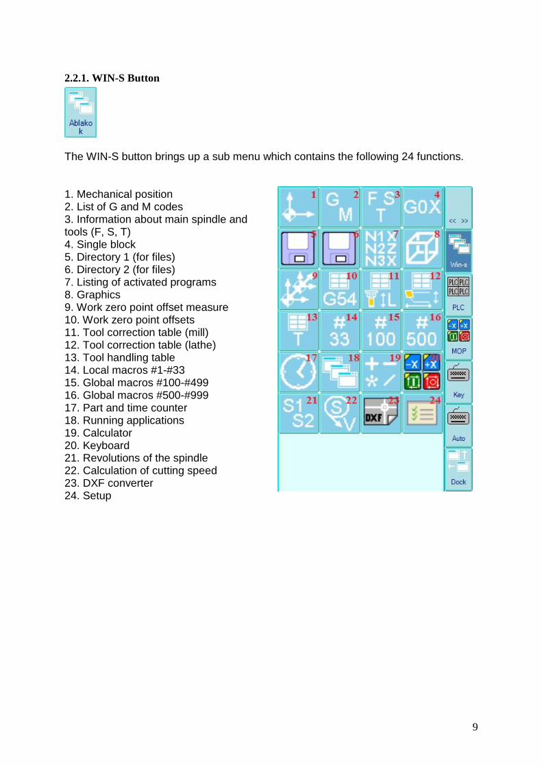
By pushing the side bar KEYPAD button, an onscreen keyboard will be displayed. It is a general keypad that has numerical buttons, and lower and upper case letters according to the language selected for the control unit. It also has function keys, basic mathematical operators (+-*/) and national characters (for accents). You can display another version of the keyboard in a horizontal position by using the SOFTKEY panel (basics - setup -”Soft input panel” button). You can also connect another keyboard to any of the four USB ports.

11
2.2.3. Software Machine Operation Panel
The software mechanical panel opens all of the functions necessary to operate the machine. The keys are exactly the same as the machine operating panel.
2.2.3.1. Operating Modes
Jog
Incremental jog
Handwheel
Reference point
Edit
Automatic operation
Manual Data Input (MDI)
2.2.3.2. Increment Selectors
For selecting 1, 10, 100, 1000 increment size (thousandth mm/inch)
2.2.3.2. Feed Rate Override Switch in 0 - 150% range. It can also affect the programmed feed rate of the rapid traverse.

12
2.2.3.4. Spindle Speed Override
The spindle RPM will be reduced or increased by 10% by pushing on the respective – or +
button in the 50-150% range. By pushing the 100% button, the programmed RPM will be set.
2.2.3.5. Program Execution Buttons
Single block execution
Conditional block skip
Optional stop
Program test
Machine lock
Dry run
Block restart
Block return
MST function lock (for testing)
2.2.3.6. Start, stop and movement buttons
Start button.
Stop button.

13
Jog Buttons
The Jog buttons are used for moving the axis in a selected direction. In case the axis moves towards a reference point, the buttons can select the axis. The arrangement of buttons can vary from one machine type to another.
Spindle Start / Stop Buttons
M3 causes the spindle to spin in a CW direction. M4 causes the spindle to spin in a CCW direction. M5 causes the spindle to stop. There are an additional 8 buttons with LEDs located on the bottom of the machine operator panel that the machine tool builder can program to their choosing, with 4 of them containing optional rapid traverse override buttons among them. A manual handle can be also attached to the machine control panel.

14
2.3. User Box
A user box is a profile set up for each individual machine operator. Each user box allows for
modifications of the control unit as well as allowing additional personal adjustments (ex. the
color of the screen, position of windows, etc.). This allows a machine to be used by several
different people. Every user has access to his own user box by creating a personal username
with an optional password. All users have an authorization number from 0 to 5, with 0
granting full authority and 5 granting the lowest authority. Any user may create a new user
box, but he can only setup an additional user box with an equal or lesser authorization
number.
2.3.1. Creating a New User Box
To create a new box, login to an existing box and select the following options on the SOFTKEY menu: SK > Setting > Security > New user
Input a new user name and then push OK. (Example shown below)
Now, you can give the full name of the user and any additional comments.
2.3.2. Setup of Password
You may setup an optional password for a user box. Otherwise, everybody may access your personal user box. In order to set up a password, select the following: SK > Setting > Security
Choose the box you wish to protect by a password, than push the button “New Password,” located in the Softkey box and then enter your password. To finalize your new password, you will be asked to confirm it by typing it again.

15
2.3.3. Modifying Your Password
SK > Setting > Security Select the user box that you wish to modify and then push the button NEW PASSWORD. You need to provide your old password before inputting a new one. Again, you must confirm the new password twice before it is finalized.
2.3.4. Cancelling Your Password
This is like modifying your password. Modify the old password, and don't put anything in the New Password field.
2.3.5. Log out from the User Box
Select the Shut down button from the SOFTKEY line. Select Shut down on the window, which will pop up.
Press OK.
2.3.6. Authorization Levels
Six different authorization levels can be used. All of them grant different rights to the user:
0: Full authorization only the builder of the machine is allowed to setup a full authorization in his user box and it is only temporary. It requires a code to be used before setting up every task. It is only valid until you restart the control unit.
1: Authorization The user can set up parameters, measure a tool or a work piece, and write individual sentences. He has no right to cancel files with the “sys” extension. They can create and edit an NC program in any memory.
2: Authorization The user has the right to set up parameters, to measure a tool, a work piece or to write individual sentences. He has no right to cancel file with “sys” extension, and hidden files neither. They can create and edit an NC program in any memory.

16
3: Authorization allowing to create and edit an NC program in any memory. The user has the right to set up parameters, to measure a tool, a work piece or to write individual sentences. He has no right to cancel file with “sys” extension, hidden, archive or write protected files.
4: Authorization The user can only create and edit an NC program in the directory: Storage Card / Programs. The user can set up parameters, measure a tool or a work piece, and write individual sentences. He does not have the right to cancel any files (ex. “sys” extension, hidden, archive or write protected files).
5: Authorization The user can only create an NC program in the directory: Storage Card / Programs. The user has no right to set up parameters, measure tools or work pieces or to write individual sentences. He has no right to cancel a file.
Attention! There are parameter bits set in the PLC (Programmable Logic
Control) that have higher authorization than the 0 level setting. If these parameter bits forbid a certain file operation, then even 0 level authorization can not modify those file operations. For more details, consult the following: NCT 201 Parameters

17
3. Operation Modes
3.1. Jog Operation Mode Jogging can be completed only while the machine is turned on if there is no EMERGENCY STOP STATUS in the above status field. After starting the operation, JOG will appear in the status field.
Choice of Direction
You will find +X, -X, +Y, -Y, +Z, -Z, and +B, -B positioning buttons on the front panel. You can start movement on the X, Y, and Z axis directly by pushing and holding the equivalent button. You can push several positioning buttons at the same time, which will allow multiple axis movement at the same time.
R
Rapid Traverse Button
By pushing the RAPID TRAVERSE button in addition to any of the other axis movement buttons, the selected axis will move at the rapid traverse rate.
Speed Selection
The speed of the axis movement is determined on the physical machine panel or the software panel.
The speed of the Rapid Traverse is a fixed value that is set by the parameter axis by axis. Usually this value is smaller than the one on the G0 rapid traverse selection.
Attention! Everything described above has been an example of the
basic operation of the axis movement. The builder of the machine may create a different set of operations for axis movement on other machines using other buttons. For details, please contact the builder of the individual machine.

18
3.2. Incremental Jog Operation Mode Incremental jogging can be completed only while the machine is turned on if there is no EMERGENCY STOP STATUS in the above status field. After starting the operation, INCR will appear in the status field.
In this operation mode, by pushing any direction buttons on the physical machine or software panel once, the axis will step forward according to the increment set up, with the speed of the feeding set.
If the machine has an NCT manual panel, the selection of the step may be done by using the stepping buttons. The size of a step made by the control unit (1, 10, 100, or 1000 increments) is always given in the least input unit of the machine. For example, if there is a metric ball screw, then the output system is metric and the least input unit definition is 0.001mm. If the control unit was set in a G20 mode (inch) and 1000 increments were selected on the display, then the feed will be 0.0394, which is the value of 1mm given in inches.
Selecting the Direction
After setting the size of the step, then pushing the direction buttons, the stepping will be started on the selected axis and move towards the selected direction.
Note: If you use larger increments and you suddenly release the Jog button, the axis movement will stop and the selected distance will not be reached. In this way, you can avoid any possible collisions.

19
3.3 Handwheel Operation Mode Handwheel Mode can be completed only while the machine is turned on and there is no EMERGENCY STOP STATUS in the above status field. After starting this mode, the status field will show HNDL.
Selecting the Step
Select the step by using the button on the physical panel of the machine or the software panel. The size of a step in the hand wheel mode shows how many increments will be stepped forward while moving the hand wheel by one pitch.
Direction
The movement of the axis is determined by the + / - directions painted on the
NCT hand wheel.
If the machine is equipped with an NCT machine control panel, you can also select the axis from the buttons X, Y, Z. By selecting the desired axis, the display for both directions (for example +X and –X) will light up.
20
3.3.1. Multiple Hand wheels
The control system may also be equipped with a total of 3 hand wheels. These hand wheels each control the movement of the X, Y, Z axes, but they are limited to each axis. If there are more axes, they have to be selected by an axis selection button and only then can they be moved using a common hand wheel.
Handwheel Movement Speed
The speed of the axes that you move with the hand wheel depends on the hand wheel step selection and how quickly you rotate the hand wheel. The axis movement starts with acceleration and stops by slowing down. There are two ways of setting the parameters for the hand wheel movement:
- The axis movement will finish according to the impulses generated by the hand wheel rotation. If the axis movement is unable to follow the impulses, then those electrical impulses will accumulate and they will move the axis after you stop moving the hand wheel.
- Even though the hand wheel generates electrical impulses that move the axis, if you suddenly stop turning the hand wheel, then the axis will also stop. Due to this, the size of the real step will not be equal to the step marked on the hand wheel.
Attention! The operation described above is simply a basic method.
The final execution itself is dependant upon the design of the machine. For example, if you use a portable hand wheel instead of a built in hand wheel that is a part of the operating panel, then you would use a selector switch to determine the steps and direction of the axis instead of the machine panel.
3.4. Reference Point Return Operation Mode To use the reference point return mode, use the following three steps:
1) Select the operation mode REFERENCE POINT by using the button on the physical panel on the machine or the software panel.
2) Before pushing the movement switch of any axis, please pay attention to the position of the machine and the tool. While in REFERENCE POINT mode, the axis will move in the direction of the reference point as long as you are pushing the movement buttons. If needed, first get to any other hand operation mode and move the tool in a position where the reference point can be reached in a straight line without crashing.
3) If the tool is in the proper position, then push the CYCLE START button, which will turn and they stay green. You will not need to move the axes one by one because they will move automatically move towards the reference point even after you have released the JOG buttons.

21
3.5. Automatic Operation Mode A program execution in automatic mode can be completed only while the machine is turned on if there is no EMERGENCY STOP STATUS in the status field. After starting the operation, AUTM will appear in the status field.
The automatic mode is an operation mode for executing programs for parts. This program may run from any memory, including a flash drive or a network, but it is supposed to copy the program to the internal memory of the control unit before you can run it.
The automatic mode may be interrupted so that it can be continued later from the very same point. There will be a more precise description in a later chapter.
3.6. Manual Data Input (MDI) This mode can be completed only while the machine is turned on if there is no EMERGENCY STOP STATUS in the status field. After starting the operation, MDI will appear in the status field.
In this mode, a special file called MDIprogCH00 is executed channel by channel. The channel number is determined by adding a double digit number after CH. For example: MDIprogCH00 is the editing field of the first channel for manual data input, while MDIprogCH01 is the second channel. The content of this can be edited at your convenience according to the description you find under the chapter about editing the automatic program.
Pushing START in this mode will start the program, while pushing STOP will end it.
3.6.1. Differences between Automatic and MDI Mode
- You cannot interrupt Manual Data Input Mode. This means that you cannot quit and then return to continue the program from the point of interruption (contrary to automatic mode). The program will always restart from the very beginning.
- In the MANUAL MODE program, you cannot search by sentence.
There are certain interruptions that you can frequently use the same way, but it's necessary to only program them once. Therefore, you do not need to input individual or multiple blocks for an operation; it is enough to simply describe the necessary activity in a single program. By interrupting the Automatic Operation Mode, you can switch to the Manual Data Input Mode and start the program.

22
For example, if a tool gets damaged, you can start the MDI program, which will do the following:
1. Stop the main spindle rotation.
2. Stop the coolant.
3. Retracts the tool to a position where you can manually intervene.
You can also use the MDI mode to easily interrupt a part program if you need to make a measuring process. In order to do this, you need to interrupt the AUTOMATIC MODE and start a measuring cycle in MDI mode. Once the cycle is finished, you can return to the AUTOMATIC MODE and continue the previous program.
In the MDI mode, the following functions work in the same way as they do in Automatic Operation Mode: Single block execution: – Conditional STOP – Conditional BLOCK – Dry Run – Lock Functions
3.7. Edit Operation Mode This is used for program editing. The following operations can only occur in editing mode:
- Editing of the parameter memory
- Uploading or saving parameters via USB
- Uploading the PLC program into the control system
You can edit the programs in any operation mode, but you cannot overwrite any program that is currently in operation.
3.8. Turn Off the Control and Restart SK > Shut down A new window will pop up; select Shut down from the roll down menu, than select OK.
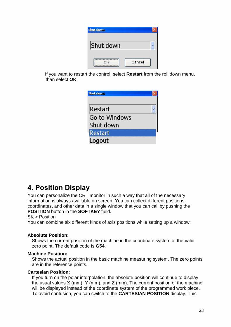
23
If you want to restart the control, select Restart from the roll down menu, than select OK.
4. Position Display You can personalize the CRT monitor in such a way that all of the necessary information is always available on screen. You can collect different positions, coordinates, and other data in a single window that you can call by pushing the POSITION button in the SOFTKEY field. SK > Position You can combine six different kinds of axis positions while setting up a window:
Absolute Position: Shows the current position of the machine in the coordinate system of the valid zero point. The default code is G54.
Machine Position: Shows the actual position in the basic machine measuring system. The zero points are in the reference points.
Cartesian Position: If you turn on the polar interpolation, the absolute position will continue to display the usual values X (mm), Y (mm), and Z (mm). The current position of the machine will be displayed instead of the coordinate system of the programmed work piece. To avoid confusion, you can switch to the CARTESIAN POSITION display. This
24
allows you to see the values in mm (inch) in the coordinate system of the work piece, like in the program, instead of the values showing the current position of the machine.
Relative Position: After reaching the reference point, the relative position is the same as the absolute position. This can be overwritten and set to zero in any preferred position. You can use it to measure the axes movement, but you cannot refer to this coordinate system with an NC code.
Distance to Go:
This shows the distance from any position to the end point of the programmed position.
End Position:
This is final point of a programmed axis movement in a block. This position is within the actual selected coordinate system of the part program. The geometric offsets of the tools are also taken into account in this position.

25
4.1. Handling the Position Window The position window will be displayed by pushing the POSITION button in the SOFTKEY / BASIC menu. It can also be displayed through the WINDOWS menu on the sidebar (Win-s). On the header of this window, you will always see the format of the current position. You can personalize the position window in order to find the information that you need. You can select one position from the following: ABSOLUTE, MACHINE, CARTESIAN, and RELATIVE. If you need to select any more positions, you can do this by pushing the NEW WINDOW button. Once the Machine Position button has been pressed down, the display header will be highlighted and the machine position will appear. If the button is pressed again, the display header will revert to the absolute position based on the current zero point. The Distance to Go and End Position displays can always be switched on or off by their respective SOFTKEY buttons.
- New window handling by pushing this button, the old window will continue to be on display, but a new window will also appear with a similar content (it may hide the old one). The windows can be moved by grabbing their header next to each other, allowing the display of several positions at the same time If you press the POSITION and F12 buttons in the SOFTKEY / BASIC menu, the four following adjustment menus will be displayed: (return from here with ESC button)
- Remainder, End Position: turn on the Dist to go, and the Endposition
- Current Value: By tuning on this function, the current value of the different axes will be displayed.
- Axis On/Off: You can turn the display of the axes on and off.
- Zero Rel.Pos: By pushing this button the value of the relative position will be 0. Each relative position can be set according to your preference, including zero.
.

26
5. Status SK > View The View menu brings up a new row of Softkey buttons, which displays the status of all currently running programs.
5.1 Program Blocks during Automatic Execution To display the currently running program, push the Program List button, which will bring up another window (see below) that shows that current program's blocks. The block under execution is highlighted in bold. This window's appearance is determined by selecting either the AUTOMATIC or MDI mode.
If you need to see which program is running in AUTOMATIC or MDI mode, then you must select the RUNNING PROGRAMS button, which is located on the SOFTKEY menu. Whichever program is running, the name of this program is highlighted in the list.
5.1.1. Program List Functions
If the window Program List is on display, the header will get darker when it is selected and the following functions will appear in the SOFTKEY line: (If you want to change to another window, touch the header of the desired window) New Window By pushing this button, the old window will continue to be on display, but a new window will also appear with similar content (it could be in front of the old one). The windows can be moved next to each other by grabbing their header. This way you can see distant program lines at the same time. It can also be useful at the jump

27
commands within a file (GOTO) because you can see the line containing the jump command and the context of the block where you have to go to. Block Search The Block Search will work only in Auto Mode. It will not work if the following sub menu buttons are shaded:
- Cycle start on - Cycle stop on - INTD status (program interrupted) - Previous block search is active
With active block search, a text field will appear on the bottom of the Program List window. Input the text you are looking for and if you get multiple results, you can
move among them by using the >> button. You can also go backwards by pushing
the LAST button. If you select the Row number soft key, the number that you typed in to the text field will lead you to that row. If there is no such block number, then the Not Found message will be displayed. It is also possible to search for a block by clicking on the arrow on the left side of the desired row, or by using the stylus of the NCT control touch screen. If the searched block was a sub-program call, the search can be continued in the sub-program. The Goto soft key button will pop up a text field with the following question:
When you select GOTO it does not execute the sentence which is before of the selected line! Are you sure you want to continue?
Your search could also be case sensitive if you use lower and/or upper case letters in your program. Running Program A window will pop up to show the programs running in Automatic and MDI modes. Edit Program The program that is in the Program list will pop up in a new window with Edit on the header. You can then edit and save the program. There are other new buttons that will appear on the SOFTKEY line:
Run - You can assign this program to run. File - The edited program can be saved with the same file name (using Save) or with a different file name and location (using Save As). Edit - This will create another set of keys that will you: Undo, Cut, Copy, Paste, Select all, Search/Replace functions Insert - There are several additional insertion functions that are used for faster editing. Block Number - This allows you to renumber the blocks according your selection or it will be use auto numbering.

28
Word Wrap - This will allow you to format long text into a shorter column. Autoscroll Stop When activated, this will display only a portion of the program that is visible in the window. Otherwise, all blocks of the program are visible as the program execution continues. Level up, Level down By using these buttons, you can control which level of the program is displayed. This can allow you to see the running macro program from the level of the calling or in greater details if you chose to go within the sub-program.

29
5.2. Graphic Display of the Tool Path
SK > View > Graphic The absolute position can be displayed (independently of the operation mode) in the graphic window. The window will be on the lower right part of the screen. The tool path will be shown as a continuous track. The rapid traverse section will appear with a red line and you will see the normal feeding as a green line.
5.2.1. Setting of the graphic display
The lines will show the model of the real tool path. You can select the choice of a display. In the menu “View setting” you can select several views, such as an isometric or a Cartesian view or a view of any of the selected planes XY, ZX, or YZ. You can even adjust the rotation of the coordinate system. The direction of their axes can also be determined by the following presets: XY Set, ZX Set and YZ Set. You can undo or redo the adjustment of the view by selecting “Undo” and “Redo” buttons.
5.2.1.1. Zoom
You have several possible ways of zooming in on the display.
1) SK > View > Graphic > Zoom Fit - The whole tool path will fill up the size of the window. Zoom In - The tool path will be larger, starting from the central point of the window. Zoom Out - The tool path will be smaller, starting from the central point of the window.
2) SK > View > Graphic > Zoom > Window A yellow rectangle will appear on the drawing. Using the buttons Zoom In or Zoom Out, you can adjust the size of the window. The “Left”, ”Right”, “Up” and “Down” buttons are for adjusting the position of the window. Press the “Set” button and the content of the selected window will fill the whole screen.
3) Directly on the touch screen you can circle the area you wish to enlarge.
You can see a either a magnifier icon or a movement icon in the left upper corner of the Graphics window. Touch the magnifier icon and circle the area you want to enlarge. After releasing the screen, the content will fill up the screen automatically.

30
5.2.1.2. Moving
You can move the drawing two different ways in the Graphic window:
1) SK > View > Graphic > Move Use the function of the buttons „Left”, „Right“, „Up”, „Down” to move the drawing. The speed of the movement depends on the button turned on (1 px”, „5 px”, „10 px”, „25 px”). The one that is being used has a darker background. For example, if the button„10 px” is on, the drawing will move left by 10 pixels when you the Left button.
2) To move the drawing directly on the touch screen:
Select the magnifier icon. Trace a line on the touch screen in the direction that you want the drawing to move towards. After releasing the screen, the drawing will move along the line you traced.
5.2.1.3. Rotation
SK > View > Graphic > Rotate The movement is similar to rotating a globe, in which case the center point is locked down. If we move the front section down, the rear section will move up. Likewise, if we move the front section to the right, the back section will move to the left.
5.2.1.4. Setting of the drawing
SK > View > Graphic > Drawing setting
You can continue to further fine-tune the ways in which the graphics are displayed by using some of the following settings:
Clear: Cancels the current drawing.
Auto Clear: Cancel the drawing which was made in the previous program. A new drawing will start when the program begins.
No draw G0:
The movements made in rapid traverse won’t be drawn.
Export: You can save the content of the graphic window as a picture. Upon pushing the button, a directory will show up. Please give a name and a format to save the picture.
Redraw: This updates the drawing by redrawing it.

31
Sketch: You can draw a sketch in the graphic window .
Pointing: Instead of straight lines, dotted lines will be used for drawing.
Split view: While this button is turned on (indicated by a darkened background), three typical views will be shown at the same time. Three different plane views (XZ, YZ, and XY) and a fourth view that is freely adjustable. If you turn on the “Split view” function, you will have to adjust the fourth view again because the previous adjustment will be lost since the function was turned off.
G53: The program parts interpreted in a different zero point system will be shown in a machine G53 coordinate system. When switched off, the program will be displayed without a work shift.

32
5.3. Macro Variables During programming, it is possible to use macros. You can give them a value, read their content or edit them under a table form. By assigning a number, you can give a value directly to that macro variable. In the CNC program you can also give a value to a macro variable indirectly. This means that instead of giving a value, you can give the variable that contains the value. For example, you can give only the variable #1–#33, #100–#499 or #500–#999. Local and global macro variables can be distinguished by different numbers and “0” and “empty” are also distinguished as numbers.
5.3.1. Local macro variables #1- #33
During programming, you can use sub-program calls. These sub-program calls can be nested inside 16 levels. Local macros have to be considered as separate macros on all levels so that they can represent the values of the current level. The names they have are the same at all levels. If you make a link, you reach the local variable of the level where the subprogram was called. While starting a program, the first level of the local macro variables will be totally cancelled. Every time a new sub-program is called, the new level will be cancelled as well. The previous content will be lost and it will be loaded by the programmed values while the subprogram is running. The content of the local macro variables will also be lost at every level while turning off the control. For example, you can see the macros #1- #33 in the table below and you can edit them. SK > View > #1- #33.
5.3.2. Global macro variables #100- #499 and #500- #999
Global macros are the same variables at all of the 16 levels of the subprogram calls. If a link is made, you reach the same global variable at every level. The content of the global macro variables #500–#999 will not be lost upon turning off the control. You can see the macros for #100-#499 and #500-#999 in a table and edit them under the following chain: SK > View > #100-#499 and: SK > View > #500-#999 respectively.

33
5.3.3. Editing of the Macro Table
New Window By pushing the New Window button, the old window will continue to be on display, but a new window will also appear with the same content (although it may hide the old one). The windows can be moved next to each other by grabbing their header, allowing the display of local variables at different levels in multiple windows.
Import The already saved table with macro variables can be imported by using the Import button, which can be found in the SOFTKEY. After importing the variables, they will be saved.
Export If you wish to create several different macro tables, you can export it by pushing the Export button, which can also be found in the SOFTKEY. Once pressed, a directory will appear that will allow you to name and save the macro table.
Undo You can undo the previous modification by using the following command chain: SK > View > #100-#499 > Undo. A window will pop up that contains the previous modifications. Then you can search for the modification you wish to undo by using the Up and Down buttons in the SOFTKEY. Once you press the Undo button, an alarm window will pop up with the question: “Do you really want to restore the selected variables?” Press “Yes.”
Redo the Undo In order to redo a previous undo, press Cancel in the SOFTKEY. A window

34
containing a list of the previous redoes will pop up. Simply select the one you wish to redo by using Up and Down buttons in the SOFTKEY and then press Cancel. An alarm window will pop up with the question: “Do you really want to restore the selected variables?” Press “Yes”.
Level +/- If a local macro table is selected, you can switch from one level to another one by using the Level + / - buttons.
Clear Current If you need to delete a variable on a macro table, select the variable and press CLEAR.
Clear All If you need to delete and empty an entire macro table, simply press the Clear All button. A new window prompt will ask, "are you sure?" Press "Yes".
Null All/Zero All If you need to set the entire macro table to 0, press the Null All button. A new window prompt will ask, "are you sure?" Press "Yes".
5.3.4. Validation of Changes
The changes you have made in a CNC program will be validated immediately, but not all at the same time. The control unit will upload macro table by the values programmed continuously while the program is running. By calling the subprogram, the new level of local macro variables will be automatically cancelled in the table. Modifications that were made by editing the table will not be necessarily validated at once. While the program is running, if you can see that the next 2 or 3 lines in the program will refer to a macro variable, then you can still change those variables in the table. The old value may still be used during the program execution because the program is not yet at that sentence, even though the control has already buffered that sentence.
5.3.5. The important Variables in one place
If you need to collect the most important variables in one window, use the following command chain: SK > View > All variables The All Variables window will pop up, allowing you to follow the value of 20 macro variables at the same time. Simply enter the name of the variable in the first column you wish to check and on the right side you will be able to continuously view its current value.

35
5.4. Messages If you need to see all of the control's messages, use the following command chain: SK > Status > All messages The window that pops up is called the Global Errors window. This same window can be called by double-clicking on the message field in the status bar.
In the message field, you can see the last error message. If there are more than one error messages, you will find a number before the text of the message, displaying the number of the messages. Between two ▼ signs, you will find the text of the last message. The ▼ signs also indicate that there are further messages.
Following the All Messages command chain through the SOFTKEY line, you can find the following functions:
Export This allows you to save the content of the Global errors window. Simply push the Export button and a directory will show up. Give a name and a format in order to save the error message. Delete (selected) To cancel the selected error messages, press Delete (selected). Delete all To cancel all the error messages, press Delete all.
By pushing the CANCEL button, the selected message (by default, the last one) will be cancelled. The last message appears also in the first line of the status field. By pushing CANCEL you can cancel the messages one by one and you won't need to call the window “All messages”.

36
5.4.1. Construction of message numbers
5.4.2. Groups of Messages
Messages can be divided into the following main groups: System Alarms: – Alarms due to failure or false setting of servo system – Alarms due to failure of position encoders – HW/SW alarms coming from the NC Other NC error messages – Reference point return errors – Errors due to moving to overtravel positions and forbidden areas Messages sent by the PLC program – There may be alarms during the operation of the machine – Messages informing the operator Error messages sent by program module buffer processor – If the program module buffer processor finds an error in the pre-processed program block, an error will be generated Error from the user macros - Error messages which are programmed by the user and will be cancelled – Messages waiting to start, also programmed by the user
Exemple: 01200600 Illegal G-code
01 2 006 00
0 -> PLC
1 -> Measuring system
2 -> Handling of channel (Programming error) (Block preparation)
3 -> Handling of channel (execution error)(Interpolator)
4 -> Macro error (#3000)
5 -> Macro message (#3006)
6 -> reserved (currently not in use)
7 -> reserved (currently not in use)
8 -> system messages in real time
9 -> system messages on the display site
Number of message: [000-999]
optional index of the message: [00-99] (pl: index of axis)
number of c hannel : 00 - > i ndepent of c hannel ( gl obál ) 01. . . 08 - > number of c hannel

37
Possible answers for the messages:
Cancelling messages by turning the power off and on In case of extremely serious or dangerous alarms, the message cannot be cancelled and the CNC must be restarted. These messages will cut the machine off from the CNC and create an emergency stop state (EMG) every time. Cancelling messages by using the CANCEL button This is the general way to cancel an error message. In case of extremely serious or dangerous alarms, the message cuts the machine off from the CNC and creates an emergency stop state (EMG) and then deletes the reference point. After using the CANCEL button, the machine can be turned on but then it must be returned to the reference point. Cancelling messages by means of pressing the START button Certain messages coming from the PLC program (or those created by custom macros) will send the control to a STOP state to await the operator’s intervention. After this operation, the machining will continue once you press the START button. Cancelling messages by the operator’s intervention Certain messages can only be canceled by eliminating the reason of the error. For example, the message LIMIT X+ can only be canceled if the slide is moved in the opposite direction manually. The limit switch can be cleared this way. All the other LIMIT type errors can also be cleared this way.

38
5.5 Backup Copy To make a backup copy of any general data, use the following command chain: SK > Settings > Prog settings In order to avoid doing this operation one by one, you can make a backup copy from the whole system, containing the following:
- macros #500-#999 - every work shift (not just G54-G59), - plc program, - messages, - Windows registry, - parameter tables, - tool storage tables, - tool offset tables
In order to backup the data, first select the System tab in the pop up window (shown below) then select the time frame of the message that you are saving and check Export logs and error.txt. and then press the Save backup button. The above mentioned files will be saved under: Storagecard/Backup/<date of saving>
39
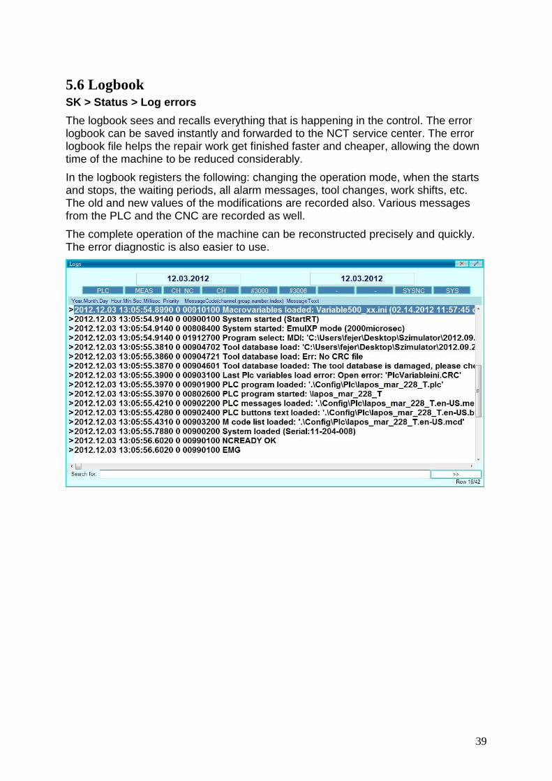
5.6 Logbook SK > Status > Log errors
The logbook sees and recalls everything that is happening in the control. The error logbook can be saved instantly and forwarded to the NCT service center. The error logbook file helps the repair work get finished faster and cheaper, allowing the down time of the machine to be reduced considerably.
In the logbook registers the following: changing the operation mode, when the starts and stops, the waiting periods, all alarm messages, tool changes, work shifts, etc. The old and new values of the modifications are recorded also. Various messages from the PLC and the CNC are recorded as well.
The complete operation of the machine can be reconstructed precisely and quickly. The error diagnostic is also easier to use.

40
5.6.1. Filtering the Messages
You can filter and relevant messages in the logbook by date or message group. Selecting the Starting Date Double click on the left side date button: Starting Date. A calendar will appear in the middle of the window.
Select the starting date.
To find the ending date, double click on the right side date button: Ending Date. A calendar will appear in the middle of the window, which causes the starting date window to disappear. Select the ending date.
You can also select the starting and ending date by the Date from and Date to buttons.
In order to display all of the messages between the selected date period, push the View Date to Date button.
In order to display all of your messages in the logbook, select the View all button.
In order to display all of the messages since the machine has been turned on, select the View Current button.
Selecting the messages by the groups The buttons under the date periods will show the different message groups. PLC PLC MEAS Measuring system CH NC Handling of the channel (block preparation) CH Handling of the channel (Interpolator) #3000 Macro error (#3000) #3006 Macro message (#3006) - - (currently not in use) - - (currently not in use) SYS NC system messages in real time SYS system messages on display side

41
By pushing the buttons (the header will be darkened), the messages in the selected group will show up. Messages related to the off buttons won’t appear in the logbook window. Order of the message entry The message entries will follow each other in a timely order in the log. As a display option, you can find two buttons on the Softkey line that can be used to set the direction of the time
From up to down Earliest date on the top
Form down to up Latest date on top Logbook File Preparation Press the button Export to begin file preparation. In the window that pops up, give the name and place of the file, then push Save. Only the content of the window – according to the selected requirements – will get into the logbook file.
5.7. Parameters SK > Service > Parameter The parameter functions make it possible to view, modify and save the values, adjustments and parameters of the control unit and PLC. For more details on how to use the parameters, see the diagnostic description of the control NCT2xx.

42
5.8. Status Display The top line of the screen is the status window, You will get a global view of the current state of the control and the machine. This display field location is static, regardless which window you open. In the first line you will find a message field. In this field the followings will be displayed: operating messages, errors of the CNC, and macros and PLC messages. You will also find the date and time in the same line.
The further lines belong to the channels. (i.e. If there is a one-channel machine, you will have only two lines). There are nine status fields and in the last field you will find the path and name of the program selected on the current channel for the automatic execution. In manual data input mode, you will find the path of the file to be used for manual data input. Possible Status Field States The lines determine priority, with the top line requiring the most priority and each consecutive one requiring less. If multiple statuses occur at the same time, a higher level state will overwrite a lower level state. 1. field 2. field 3. field 4. field 5. field 6. field 7. field 8. field
EDIT SBLOCK NSCH INTD (DWL) [S]
PLC # NC
AUTM JOG GOTO STOP DRY RUN
* KLAV
MDI INCR START F0% ® PLC
HNDL STOP F=0 ! EMG
REF MOV FLOCK
SBEX POS TEST
0.001-1 MLOCK
mm/ inch
REF
1 First status field states – MDI: Manual data input mode – AUTM: Automatic operation mode, program execution from the memory – EDIT: Edit mode 2 Second status field states

43
– JOG: Jog – INCR: Incremental jog – HNDL: Handwheel – REF: Reference point return – SBEX: Block restart 3 Automatic operation and manual data input mode – START: Start – STOP: Stop – NSCH: Block search – GOTO: Go to a block 4 Fourth status field states – INTD: Automatic execution interrupted 5 Interpolator states – DWL: Waiting because of G4 (only the rest of time is displayed in seconds) – MOV: Moving of any axis (interpolator started) – POS: Waiting in a position for signal – STOP: Stop feeding state – 0,0010: Increment size 1 – 0,0100: Increment size 10 – 0,1000: Increment size 100 – 1,0000: Increment size 1000
Attention! Each machine is different. Ask the machine tool builder about the marks of the scales and their exact values. – inch/mm: Depends on the selection: mm or inch – F0%: The override button is turned to 0% – F=0: The programmed feed is 0 6 Sixth status field states – PLC: Execution of PLC function is on – Dry Run: Dry run 7 Seventh status field states – *: Scaling – ®: Rotation active – !: The common zero shift is not zero – #: Mirroring 8 General NC states – NC: No NC ready signal – KLAV: No reference point on any axis – EMG: Emergency state – REF: No reference point on any axis – TEST: Test mode – MLOCK: Machine lock

44
– FLOCK: Function lock – PLC: PLC is not running
5.9. Part and Time Counter SK > Settings > Times/Counters This displays the different time and part counters. Apart from the operating time, the values are free to overwrite. Power on time: Unmodifiable clock that begins when the machine is initially delivered. Operation time: The time that the machine spends in automatic start state. It can be reset to zero by pushing the Operation time reset button in the SOFTKEY line. Cutting time: The time that the machine is in feed movement and not in rapid traverse. It can be reset to zero by pushing the Cutting time reset button in the SOFTKEY line. Interval meter: A timer for general use. It can be reset to zero by pushing the Interval meter reset button in the SOFTKEY line. Part time: The part time counter measures the time spent in the automatic start state. This will be reset to zero automatically by starting a new part program. Operation of the part counter When starting machining of a series of parts, the PARTS COUNT counter must be set to 0. Set the PARTS REQUIRE value to the number of parts that will be produced. The PARTS COUNT counter is increased by one if the code M02 or M30 is read. The value of parameter N2305 Part Count M should be 0 for this counting mode. If other M codes need to be used, (e.g. M99), set the above mentioned parameter value to the appropriate M code number, in this case to 99. If the number of machined parts reaches the number of parts to be produced, i.e. PARTS COUNT = PARTS REQUIRED, then the CNC will send a message to the operator that the parts count has reached the required number. Further operation details are determined by the machine tool builder, see the supplementary manuals.

45
6. Program
6.1. Single block SK > Program > Single block With this function you can give an optional F (feed), S (spindle), T (tool), G (G-function), M (M-function) command or even execute a whole block containing one or more commands.
1. Press any of the buttons (JOG), (incremental JOG), or hand wheel on the machine operation panel and the control unit will change the operation mode. The Single block window will be displayed on the left lower corner of the screen.
2. If you cannot find the window, you have to choose Win-s on the sidebar and push the G0 X button and the single block window will pop up every time.
3. In order to activate the window, click on to the top tab of the window and once the header is darkened, then the window is activated.
4. Type in the M3 S1000 X100 command line in any of the rows. You can even overwrite any of the previous command lines.
5. Push ENTER on the screen keypad and SBLOCK will appear on the status screen.
6. Press the Cycle Start button and the block will be executed. The main spindle will start to rotate with 1000 RPM, then the slide will position to X=100 mm.
In the Single block window, you can store a maximum of 20 blocks. You can select any of the blocks in this window and the selected block will be executed.

46
6.2. CNC Program Creating and editing a CNC program can be done while the machine is still working. The program can be edited while another program is in operation. You can choose between writing a new program or editing a preexisting program.
6.2.1. Creating a new CNC program
SK > Program > Edit 1. To create a new CNC program, select the Edit mode. A new window will pop
up and Edit: Untitled will be on the header. 2. Turn on the keyboard tab on the right or the left side of the screen. 3. You can edit the program either by the virtual keypad or by the external
keyboard connected to the USB port. 4. After the editing is finished, close the window (click on the red X on the
header) and a message will show up, asking the following: “The text in the file has changed. Do you want to save the changes?”
5. Answer “Yes” then you can name the file and directory where you want to save the program, which can be done by pushing the SAVE button.
6. You can also save the program by pushing the FILE button on the Softkey line and then you can push the Save button to save the file immediately. If you select the Save As button, you can give a new name, or select an old file name which is already in the directory, which will then be overwritten with the new content.
6.2.2.
Editing an existing CNC program
1. To edit a program already existing, select the file first, which is possible by using one of the following command chains: SK > Program > Directory1 or SK > Program > Directory2. This will bring up the directory window.
2. Search the part program that you wish to edit. You will be able to open only programs with .prg or .txt extensions.
3. Double-click on the desired program file and it will open up and you can start editing it.
4. After you are finished editing, click on the File button on the Softkey line. You can overwrite the original file by clicking on Save or you can also create a new file name by using Save as.

47
5. You can also save the file by clicking on the red X on the header of the window. The following message will show up in a window: “The text in the file has changed. Do you want to save the changes?” Push YES.
6. You can now give the file a new name and determine the directory where you want to save the program. Once completed, push the SAVE button to finalize.
6.2.3. Helping Functions by Editing
SK > Program > Edit > Edit
Undo: This will undo the last operation.
Cut: Select a part of or the whole text by highlighting it. Press the Cut button. The part you selected will disappear. The content you cut will be placed in a temporary storage and it will be copied from there to any place that you select when you press Paste.
Copy: Select a part of or the whole text by highlighting it. Press Copy button. The text selected will be put in a temporary store without removing it from the main text. The content you copied will be placed in a temporary storage and it will be copied from there to any place that you select when you press Paste.
Paste: The content of the temporary storage that is copied to the place selected by the cursor when you press Paste.
Select all: The whole content of the editing window will be selected.
Search/Replace: Two text fields will appear down in the editing window: Looking for and Change to. The content of SOFTKEY will also be changed. Only the Cancel button will be active.

48
Use "find" field to locate any phrase that you are looking for within the program. The window will jump to the first result and select the line with the phrase. In case of several results, you can navigate among them by using the Last and Next buttons. You can replace any text that you put in the "find" field by using the Replace button once you've filled out the "Change to" text field.
6.2.4. Program Execution in Automatic operation mode
After you have created and edited a part program, you can select it to run in automatic mode.
1. To select the program to run, select one from either of the following directories: SK > Program > Directory 1 or Directory 2
2. Move the cursor to the program file you wish to run and press Run. 3. Select AUTO mode in the machine operation panel. 4. If there is a multi-channel machine, select the channel that will run the
program and it will be loaded into the automatic execution storage field.
5. Push the Cycle start button and the program execution will start. Note: If the machine operation panel of the screen is not activated, you can either change the operation mode on the panel of the machine tool or you have to activate the screen's panel.
49
7. Offsets
7.1. 0-points (Work shift)
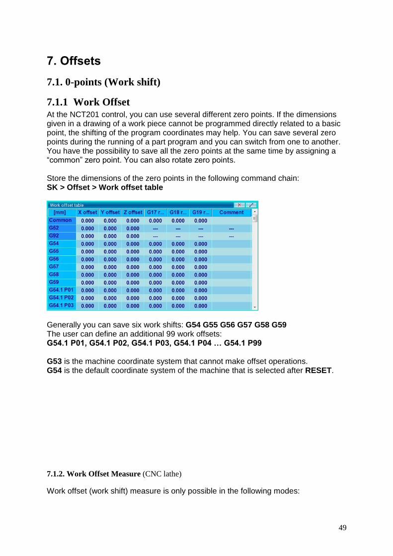
7.1.1 Work Offset At the NCT201 control, you can use several different zero points. If the dimensions given in a drawing of a work piece cannot be programmed directly related to a basic point, the shifting of the program coordinates may help. You can save several zero points during the running of a part program and you can switch from one to another. You have the possibility to save all the zero points at the same time by assigning a “common” zero point. You can also rotate zero points. Store the dimensions of the zero points in the following command chain: SK > Offset > Work offset table
Generally you can save six work shifts: G54 G55 G56 G57 G58 G59 The user can define an additional 99 work offsets: G54.1 P01, G54.1 P02, G54.1 P03, G54.1 P04 … G54.1 P99 G53 is the machine coordinate system that cannot make offset operations. G54 is the default coordinate system of the machine that is selected after RESET.
7.1.2. Work Offset Measure (CNC lathe)
Work offset (work shift) measure is only possible in the following modes:

50
JOG, INCR, HNDL
1. SK > Offset > Measure > Work offset measure
2. Select the work offset (work shift) number. The coordinate system of the part program 0-point will be selected.
Double-click the darker field under: Work offs No: Scroll down to the desired work offset number (G54-G59) (the selected coordinate system will not be activated this time, it will be used only for the work offset measuring)
3. Select the tool offset number that will be used during the work offset measuring. Double click on the field right to the Tool offset No then type in the offset number and press ENTER. If you select an invalid offset number (which is not in the offset table), the field background will be yellow. The control will use the stored offset values of the tool from the selected offset number. The 4 values are: length, tool tip radius, wear offset and tool radius location (this is an imaginary tool tip locator). 4. Measure the work offset in the Z direction by using the following directions:
Turn on the main spindle.
Move the tool to the part and cut the face about 1/2" (12 mm) long.
Move the tool back only in X direction until the part is cleared.
Stop the spindle.
Type in 0 in the Z-axis field of the measuring position and then hit ENTER. The work offset will be calculated and recorded in the offset table.
The work shift is not necessary in X direction on the CNC lathe. The 0 point is always on the centerline of the spindle.
7.1.3. Editing the Work Offset Table
Call the Work offset table through the following command chain: SK > Offset > Work offset table. To edit the table, touch the cell that you wish to overwrite and using an external keyboard or a keypad, press ENTER.
You can find the following editing functions in the SOFTKEY line:

51
Clear all: You can quickly cancel all values by using Clear all, which will cause all of the offset values to change to 0. Clear group: You can quickly cancel all values of a selected work offset by using Clear group, which will cause all of the offset values to change to 0. Save: You can save all the values in the offset table. The control unit will not be able to store more than one work offset table. Export: If you wish to create several different work offset tables, you can export them by pressing the Export button. A directory will show up and you can type the name of the table and the place where you wish to save it. Import: You can import a work offset table which was already saved in a different directory. Undo: You can undo any previously made modifications. A window will pop up with all of the recent modifications and you simply need to select the one you wish to undo by using Up and Down buttons in the SOFTKEY line. After the selection is highlighted, press Undo button and an alarm window will pop up, asking you the question: “Do you really want to restore the selected workoffset/tooloffset values?" Press Yes. Redo: You can cancel a previous undo operation by pressing Redo in SOFTKEY line. A window will pop up with the previous undo values. Select the modification you wish to redo by using the Up and Down buttons. After the selection is highlighted, press the Redo button and an alarm window will pop up, asking you the question: “Do you really want to restore the selected workoffset/tooloffset values?" Press Yes.
*** Attention! Any operations made on work offset tables will immediately
overwrite the offset register. The running program will take this into account only if you restart the program from the very beginning. You can also interrupt the program execution by hitting the RESET button. In this case, the coordinate system will be overwritten, but still the modified value won’t be considered until the program will recall the modified coordinate system. If you make a careless overwriting of the coordinate system, it won’t create an immediate problem during the program execution. The impact will only show up the next time that the program runs, so be very careful when you overwrite the work shift values.
7.1.4. Selection of work zero point in a program
See NCT 201 program description for more details.
7.2. Tool Offsets The tool offset values are used for the tool length and tool nose radius compensation in the CNC program. The tool offsets are collected in the offset tables. Each time a tool offset is called by the program, the data of the selected offset will be used in the program. The programmed path of the tool will be modified by the offset values. .

52
7.2.1. Tool offset measuring (on the CNC lathe)
The tool offset can be measured in the following operation modes: JOG, INCR, HNDL
.1 SK > Offset > Measure > Tooloffset measure
2. Select the work offset (work shift) number. The coordinate system of the 0-point part program will be selected.
Double-click the darker field under Work offs No. Scroll down to the desired work offset number (G54-G59). The selected coordinate system will not be activated this time, it will only be used for the tool offset measuring.
3. Select the tool offset number that will be used during the work offset measuring then double click on the field right to the Tool offset No and type in the offset number and press ENTER.
If you select an invalid offset number (which is not in the offset table), the field background will be yellow. The control will use the stored offset values of the tool from the selected offset number. The 4 values are: length, tool tip radius, wear offset and tool radius location (this is an imaginary tool tip locator) 4. Select the direction of the imaginary tool nose. It will determine the orientation of the tool's cutting edge, relative to the surface of the part.
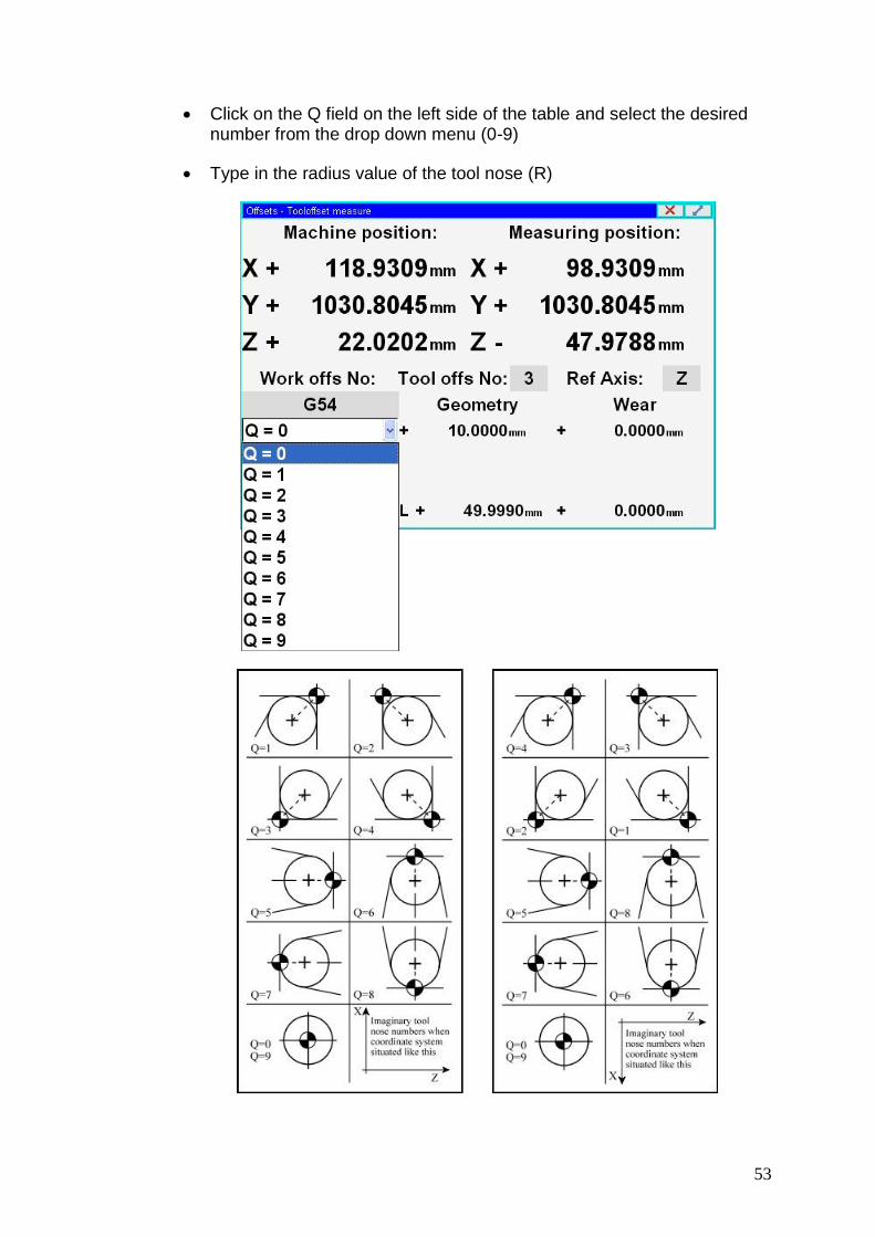
53
Click on the Q field on the left side of the table and select the desired number from the drop down menu (0-9)
Type in the radius value of the tool nose (R)

54
If you are not going to use the tool nose radius compensation, operation 4 can be skipped.
5. Move the tool tip to a known point in the selected coordinate system.
Measuring the tool in X direction
You can create a new diameter by turning the stock or you can use a known diameter for tool measuring.
Turn on the main spindle.
Jog the OD turning tool to the stock surface and take a cut across the surface about 1/2 inch (12mm) long or touch off the known surface.
Move the tool back only in the Z direction until the part is cleared.
Stop the spindle and measure the diameter of the stock you just cut.
Type in the measured value in the X-axis field of the measuring position and then hit ENTER.
The geometry offset will be calculated and recorded in the offset table.
Measuring the tool in Z direction You can create a face in the Z direction by turning the stock or you can use a known face for tool measuring.
Turn on the main spindle.
Jog the tool to the stock surface and take a skim cut across the face (new surface) or touch off of the known surface.

55
Move the tool back in the X direction only until the stock is cleared.
Stop the spindle.
Type in 0 in the Z-axis field of the measuring position and hit ENTER. The geometry offset will be calculated and recorded in the offset table.
To make the measured tool offset active, call this tool offset in the part program or
in the single block mode.
7.2.2. Editing the Tool Offset Table
Call the work offset table through the following command chain: SK > Offset > Tool offset table. To edit the table, touch the cell that you wish to overwrite and press ENTER using an external keyboard or keypad. .
You can find the following editing functions in the SOFTKEY line: Clear all: You can quickly cancel all values by using Clear all, which will cause all of the offset values to change to 0. Clear group: You can quickly cancel all values of a selected tool offset by using Clear group, which will cause all of the offset values to change to 0. Save: You can save all the values in the offset table. The control unit will not be able to store more than one work offset table. Export: If you wish to create several different tool offset tables, you can export them by pressing the Export button. A directory will show up and you can type the name of the table and the place where you wish to save it. Import: You can import a tool offset table which was already saved in a different directory. Undo: You can undo any previously made modifications. A window will pop up with all of the recent modifications and you simply need to select the one you wish to undo by using Up and Down buttons in the SOFTKEY line. After the selection is highlighted, press Undo button and an alarm window will pop up, asking you the question: “Do you really want to restore the selected workoffset/tooloffset values?" Press Yes. Redo: You can cancel a previous undo operation by pressing Redo in SOFTKEY line. A window will pop up with the previous undo values. Select the modification you

56
wish to redo by using the Up and Down buttons. After the selection is highlighted, press the Redo button and an alarm window will pop up, asking you the question: “Do you really want to restore the selected workoffset/tooloffset values?" Press Yes.
***
Attention! Any operations made on work offset tables will immediately overwrite
the offset register. The running program will take this into account only if you restart the program from the very beginning. You can also interrupt the program execution by hitting the RESET button. In this case, the coordinate system will be overwritten, but still the modified value won’t be considered until the program will recall the modified coordinate system. If you make a careless overwriting of the coordinate system, it won’t create an immediate problem during the program execution. The impact will only show up the next time that the program runs, so be very careful when you overwrite the work shift values.

57
7.3. Orientation and Offset of the main spindle With this function you can set the orientation angle of the spindle. This is the angle position to which the spindle will rotate upon the M19 command. If it is a multi-spindle machine, the orientation angle can be adjusted for each of the spindles separately.
7.3.1. Setting the orientation position
1. SK > Offset > Spindle offset. 2. In the Phase Shift Calculation pop up window, select Orienting position
calculation in the drop down menu next to the Type line. 3. Double click in the first cell of the table in the Spindle line and a drop down
menu will appear. 4. Select the spindle orientation angle you wish to adjust. 5. Next to the Calculation value line, you will find the current position of the
spindle expressed in impulses. You can choose between the following two options:
You can give the absolute angle position of the spindle if you know the null-angle position (locate this in the manual or contact the machine tool builder). Input the absolute angle position next to the Offset value, then check the small box next to the Offset in angle line and press Set offset. The spindle will orient to the angle set when you use the M19 command.
You can rotate the spindle in a position you know (i.e. aligning the flat surface of a tool parallel to an axis) as a reference point. To set a certain angle, turn the tool in the angle that you wish. Input the angle of the rotation next to Offset value, then check the small box next to the Offset in angle line and press Set offset. The spindle will orient to the angle set when you use the M19 command.
Suggestion: You can give the offset in increments as well if you know the resolution of the encoder of the spindle.
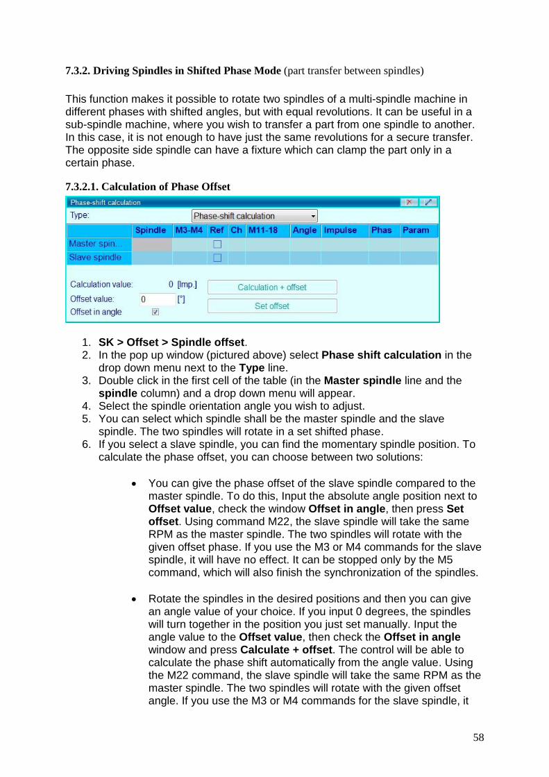
58
7.3.2. Driving Spindles in Shifted Phase Mode (part transfer between spindles)
This function makes it possible to rotate two spindles of a multi-spindle machine in different phases with shifted angles, but with equal revolutions. It can be useful in a sub-spindle machine, where you wish to transfer a part from one spindle to another. In this case, it is not enough to have just the same revolutions for a secure transfer. The opposite side spindle can have a fixture which can clamp the part only in a certain phase.
7.3.2.1. Calculation of Phase Offset
1. SK > Offset > Spindle offset. 2. In the pop up window (pictured above) select Phase shift calculation in the
drop down menu next to the Type line. 3. Double click in the first cell of the table (in the Master spindle line and the
spindle column) and a drop down menu will appear. 4. Select the spindle orientation angle you wish to adjust. 5. You can select which spindle shall be the master spindle and the slave
spindle. The two spindles will rotate in a set shifted phase. 6. If you select a slave spindle, you can find the momentary spindle position. To
calculate the phase offset, you can choose between two solutions:
You can give the phase offset of the slave spindle compared to the master spindle. To do this, Input the absolute angle position next to Offset value, check the window Offset in angle, then press Set offset. Using command M22, the slave spindle will take the same RPM as the master spindle. The two spindles will rotate with the given offset phase. If you use the M3 or M4 commands for the slave spindle, it will have no effect. It can be stopped only by the M5 command, which will also finish the synchronization of the spindles.
Rotate the spindles in the desired positions and then you can give an angle value of your choice. If you input 0 degrees, the spindles will turn together in the position you just set manually. Input the angle value to the Offset value, then check the Offset in angle window and press Calculate + offset. The control will be able to calculate the phase shift automatically from the angle value. Using the M22 command, the slave spindle will take the same RPM as the master spindle. The two spindles will rotate with the given offset angle. If you use the M3 or M4 commands for the slave spindle, it
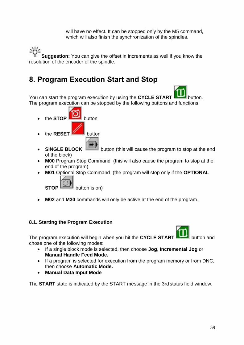
59
will have no effect. It can be stopped only by the M5 command, which will also finish the synchronization of the spindles.
Suggestion: You can give the offset in increments as well if you know the resolution of the encoder of the spindle.
8. Program Execution Start and Stop
You can start the program execution by using the CYCLE START button. The program execution can be stopped by the following buttons and functions:
the STOP button
the RESET button
SINGLE BLOCK button (this will cause the program to stop at the end of the block)
M00 Program Stop Command (this will also cause the program to stop at the end of the program)
M01 Optional Stop Command (the program will stop only if the OPTIONAL
STOP button is on)
M02 and M30 commands will only be active at the end of the program. 8.1. Starting the Program Execution
The program execution will begin when you hit the CYCLE START button and chose one of the following modes:
If a single block mode is selected, then choose Jog, Incremental Jog or Manual Handle Feed Mode.
If a program is selected for execution from the program memory or from DNC, then choose Automatic Mode.
Manual Data Input Mode The START state is indicated by the START message in the 3rd status field window.

60
8.2. Cycle Stop
To cancel the START state, press the STOP button during the program execution and the axes will slow down and stop. The execution of M, S, T, and B functions will be continued until the end of block. The STOP state is indicated by the STOP message in the 3rd status field window. The STOP button is ineffective in the following cases:
G63, i.e. state of override inhibit.
If certain values of #3004 variable are present
During thread cutting G33, thread cycle G76 and tapping cycles G74 & G84.
8.3. Reset
If the RESET button is pressed during program execution, the START or STOP state will be canceled and the axes will decelerate and stop. In an operation where the feed override or the STOP button can't stop the cycle (i.e. G33,G74,G84), the RESET button can be used instead. Certain global messages are also cleared from the message field of the status bar when the RESET button is used. The PLC program stops the spindle rotation and suspends all operations which are currently under execution. The RESET button has other effects in different modes as well. Reset in Automatic Operation Mode If the RESET button is pressed during the automatic operation mode, there won’t be any INTD (interrupted) states, the program execution will stop fully, and the cursor will jump to the first line of the program. If you push the START button again, the program execution will start again and the control will be reset to its basic state, which is set by the parameters. The program execution can only be continued from a block that was interrupted using the Block search command. Please see chapter 11.6 “starting of automatic operation mode after block search”. Reset in Manual Data Input Mode If the RESET button is pressed during the manual data input mode, the program execution is interrupted and it cannot be restarted from that interruption point, only from the very beginning. Reset in Single Block Mode If the RESET button is pressed during the single block mode, then the block is cleared from the buffer. If the same block needs to be executed again, the single block must be reselected and the ENTER key in the SOFTKEY line must be pressed again.
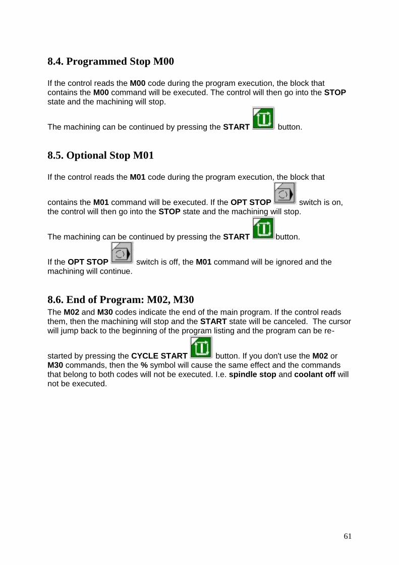
61
8.4. Programmed Stop M00 If the control reads the M00 code during the program execution, the block that contains the M00 command will be executed. The control will then go into the STOP state and the machining will stop.
The machining can be continued by pressing the START button.
8.5. Optional Stop M01 If the control reads the M01 code during the program execution, the block that
contains the M01 command will be executed. If the OPT STOP switch is on, the control will then go into the STOP state and the machining will stop.
The machining can be continued by pressing the START button.
If the OPT STOP switch is off, the M01 command will be ignored and the machining will continue.
8.6. End of Program: M02, M30 The M02 and M30 codes indicate the end of the main program. If the control reads them, then the machining will stop and the START state will be canceled. The cursor will jump back to the beginning of the program listing and the program can be re-
started by pressing the CYCLE START button. If you don't use the M02 or M30 commands, then the % symbol will cause the same effect and the commands that belong to both codes will not be executed. I.e. spindle stop and coolant off will not be executed.

62
9. PROGRAM EXECUTION INTERVENTION
9.1. Conditional Block Skip
You can program a conditional block skip /n at the beginning of a block. The "n"
represents the block number. There is a block skip switch button on the
operator's panel for activating the /n command. If the switch is on, then the block will
be skipped. If it is off, then the block will be executed. If you want the block skip command to be recognized in the proceeding block, set the Program/Execution Config parameter (N1337) CIBB bit to 0. In this case, the conditional block skip command suppresses the block buffering. If you use the G41 or G42 commands, the contour will distort. Due to the block buffering, it is enough to set the conditional block switch during the execution of the previous block.
If the /n command does not suppress the block buffering, set the
Program/Execution Config parameter (N1337) CIBB bit to 1. In this case, if you use the G41 or G42 commands, then the contour will not distort but the conditional block switch must be set before program execution.
The block skip switch button can be selected in the software machine panel or in the NCT machine operator's panel. The control can handle another 8 conditional block switches, which can be used optionally.
9.2. Increasing the Feed rate Using Rapid Traverse Jog Button If the axes are moving at the programmed feed rate during program execution, the
rapid traverse jog button can be pressed and the control will increase the feed rate. If the rapid traverse jog button is released, the feed will be reset to the programmed feed rate. The acceleration will be determined by the value set at parameter N0313 Feed MULT. The programmed feed value will be multiplied by the number set at this parameter. If the value of this parameter is 1, the feed rate remains unchanged even when pressing the rapid traverse button. If the value is set for 2, the feed will be doubled.

63
10. DEBUGGING THE PART PROGRAM
The following functions help the testing and debugging of the part program:
Single Block Execution
Dry Run
Locking Possibilities
Test Run
Calculation of the Cutting Speed
Description of the G and M Codes These functions are not separate operation modes, but conditions influencing the program execution in the automatic mode.
10.1. Single Block Execution Single Block Execution can be selected during the automatic and the Manual Data Input Mode. The control stops after the execution of each block. An exception is when thread cutting blocks (G33) follow each other. Another exception is when the suppression of a single block execution has been programmed by giving the macro variable #3003=1. The machining continues with the CYCLE START button.
10.2. Dry Run (all feed rates at high speed)
The DRY RUN button can be turned on in the software machine panel or in the NCT machine operator's panel. Once turned on, all feed movement is at a higher speed, according to the value set at the parameter. It executes every movement at the mm (or inch) / minute feed rate, independent of whether G94 or G95 is programmed.
Note: Generally the DRY RUN button can only be activated in one of the manual operation modes while the axes are stopped. Further details are available from the machine tool builder of each individual machine.
10.3. Machine Lock Function If the switch is on, then the interpolator does not give out any command to the position control loop of any axis. Also, the PLC can not execute functions at all either.
If you use the NCT machine operator's panel, use the Machine Lock button to switch on this function. The locked state of the machine is indicated by the M.LOCK caption in the 8th field of the message panel.

64
The machine lock and dry run functions can be combined, meaning that both can be switched on at the same time. The POSITION screen and the GRAPHIC POSITION screen show the path already drawn. If the dry run switch is on, then the feed is high. If it is off, then the feed is at the programmed feed rate value. If the machine lock is switched off, then the momentary axis positions can be seen again on the POSITION screen of the control unit.
Note: Generally the MACHINE LOCK button can only be activated in one of the manual operation modes while the axes are stopped. Further details are available from the machine tool builder of each individual machine.
10.4. Function Lock
The Function Lock button does not allow the control to execute any functions sent to the PLC (i.e. M, S, T, B). To activate this function, press the button on the software machine panel or in the NCT machine operator's panel.
10.5. Axis Lock This function allows you to pick out any single axis and lock it separately. This way, any other axes that are not locked down can still move freely. The different auxiliary functions and axes locking possibilities can be combined optionally. For example, it is possible to only lock a single axis while all other functions operate normally. Further details are available from the machine tool builder of each individual machine.
10.6. Test Run
To activate this function, press the Test Run button on the software machine panel or in the NCT machine operator's panel. The test state is indicated by the TEST caption in the 8th field of the status bar. When the key is activated, the interpolator does not give out any command to the position control loop of any axis. Also, the PLC can not execute functions at all either. When the control is in the TEST state, it can perform the syntactic and graphic test of the program. This way, the program execution (including the interpolation) is much faster than if the MACH LOCK and DRY RUN functions were being used simultaneously.
If the TEST RUN button is OFF, then the current axis positions can be seen again in the position display of the control panel.

65
Note: The TEST RUN button can only be activated in one of the manual operation modes while the axes are stopped. Further details are available from the machine tool builder of each individual machine.
10.7. Calculation of Cutting Speed SK > MIX > Velo calculator
This window helps calculate different speeds and feedrates.
10.7.1. Constant cutting speed calculation (G96, G97)
The CNC control calculates the spindle speed, which is proportional to the specified surface speed at the position of the programmed coordinate value on the X axis. Cutting Speed Calculation helps give a value for cutting speed during programming. Further details of the programming will be found in the description of the programming manual. If the Cutting Speed Calculation window is active (the header is highlighted), the following buttons will be found in SOFTKEY line: G94 - G95 - G96 - G97 - Copy - G20 - G21 For calculating constant cutting speed, press the G96 button. The descriptions of the different windows will change according to the selected calculations.

66
.
Type in the values in the fields you selected and the result will be put in the lower window pane.
Feed selection by mm (inch) / minute (G94) and mm (inch) / revolution (G95)
G94: mm/minute or inch/minute or degree/minute feed G95: mm/revolution or inch/revolution or degree/revolution feed
.
10.8. Description of G and M codes
SK > MIX > G codes or SK > MIX > M codes The G and M codes are organized in groups. Within a group only one code can be activated. This window contains the list of the codes and shows the group division of G or M codes and shows which code is currently activated in the group (the activated one has a darker background). If any of the code windows are activated, the following buttons can be found in the SOFTKEY line: M / G codes: With this button you can switch between the G and the M code windows. If you select the G codes button, then the window will change to M codes and vice versa. New window: You can open another G/M code window by setting the old one for checking the G codes and the new one for M codes. This way you can see both

67
windows at the same time. All: If this button is switched on (darker background), both groups of codes will appear separately. If it switched off, then the codes will appear together without the group display. Comment: If this button is switched on (darker background), a description of each code will appear.

68
11. INTERRUPTING AND RESTARTING THE AUTOMATIC
OPERATION
In many cases the automatic operation needs to be interrupted and restarted at a different time when the machining needs to be continued. There are several scenario cases for this, listed below:
During machining, the program may need to be corrected if there is a syntactical error.
In case of a tool breaking, then the broken tool must be retracted and replaced, before the machining can be continued with the a new tool (and possibly new offset values).
During certain parts of the machining, if the results need to be checked and the machining needs to be continued later on.
If there is an obstacle during the machining (for example, if a fixture is in the way of the tool path and it needs to be corrected).
If the machining has to be paused in case of power outage and the machining needs to be continued from the interruption point.
The above cases require different types of intervention from the operator and they must be corrected by means of different control services, which are listed below.
11.1. Interrupting the Automatic Operation During the automatic operation, the following interventions can cause an interrupted state:
Emergency stop state (when pressing the EMERGENCY STOP button)
Changing the operation mode The interrupted state is indicated by the caption INTD in the 3rd field of the status bar. In the interrupted state, lots of manual intervention can be done on the control, which can be registered or canceled when the program will restart.
11.2. Restarting the Automatic Operation The automatic operation can be restarted in three ways from the INTD state:
Unconditionally
The BLOCK RESTART condition
The BLOCK RETURN condition In the first case, if we moved the slide away from the point of the interruption, the slide will go to the end point of the block. If the program has increment commands, the slide will go to the very first absolute positioning point following the initial interruption, then it will go back to the original path.

69
In the second case, it goes to the start position of the interrupted block and it will re-run the whole block. In the third case, it moves back to the interruption position and continues the machining from there.
11.3. Unconditional Restart the Automatic Operation
If the automatic operation is started unconditionally from an interrupted state (INTD), after the CYCLE START button is pressed, the control goes to the end position of the interrupted block and the machining will continue from there. The typical applications of this function are the following:
The errors must be canceled in order for the machining to continue. In this case the error messages were coming from the program preprocessor module or from the PLC.
During the machining, the cutting parameters might need some changes. It could be the change of the spindle revolution (S) or the feedrate (F) by means of manual data input. The machining can be continued afterward.
In some simple cases, the end position or measure data needs to be modified without the part program modification.
If there is an obstacle of the machining and it needs to be corrected (i.e. a fixture is in the way of the tool path).
11.3.1. Interrupting Simple Movements
1st case: Interruption of a linear interpolation parallel to an axis in a G40 state. Let us examine the sections of the following sample programs:Program No 1: ... N60 G90 G0 X30 Y10 N70 Y60 N80 X60 ...
Program No 2: ... N60 G90 G0 X30 Y10 N70 G91 Y50 N80 X30 …
The Programs No. 1 and 2 are moving on the same tool path. However the data specification of the 1st one is absolute, while the 2nd one is incremental. The interruption occurs in block N70. The movement was stopped at the position X=30, Y=30. The automatic mode was interrupted by the operator and the slides were moved to position X=10, Y=40 by manual operation. He returns to automatic mode afterwards and presses the START button. Then the movement programmed in block N70 will be finished. The Y Axis moves to the programmed position Y=60, regardless of how the program was written. The X Axis does not move in block N70, it only returns to the programmed original tool path in block N80, where the X movement was programmed. If there are several blocks without the X

70
axis programmed, the X axis will go back to the original path in the block, whichever contains the X command. You can have the same movement when you switch over to single block mode at the beginning of the block N70 and move the slides away manually then return to the previous point. We can press CYCLE START afterward. 2nd case: Interruption of a linear interpolation not parallel to an axis in a G40 state. Let us examine the sections of the following sample programs: Program Nr. 1: ... N40 G90 G0 X20 Y10 N50 X95 Y55 N60 X120 ...
Program Nr 2: ... N40 G90 G0 X20 Y10 N50 G91 X70 Y45 N60 X25
… The Programs No. 1 and 2 are moving on the same tool path. However, the data specification of the 1st one is absolute, while the 2nd one is incremental. The interruption occurs in block N50. In position X=45, Y=25 the movement is stopped, the automatic mode is interrupted and the axes were moved to position X=45, Y=70 by means of manual operation. Afterwards, we return to the automatic mode and press the START button. The movement that was programmed in block N50 will be finished. The X and Y-axis were moved along the oblique straight line from their momentary position to the programmed position X=95, Y=55. It doesn’t matter if the tool path was written in absolute (program No. 1) or incremental programming (program No. 2). We can have the same movement in the following way when you switch over to single block mode at the beginning of the block N50 and move the slides away by manual operation, then return to the previous point. We can press CYCLE START afterward.
11.3.2. Interrupting the Drilling Cycles
Look at the following cycle: ... G17 G90 G81 X100 Y70 Z–60 R2 F200 ... Due to the interruption, the canned cycle consists of 3 partial blocks: 1st partial block: Positioning in the selected plane. This block will be handled by the control as though it only had one or two programmed coordinates. (G0 X100 Y70)

71
2nd partial block: Positioning to the point R. This partial block is a positioning block along an axis. In this example, the Z-axis is moving to the position specified by the address R: (G0 R2) 3rd partial block: Hole machining and retraction to the initial position (G98) or to R-point (G99). In this case, the end position of the partial block is the initial position of the R-point. At the end of all three partial blocks, the control stops in the single block mode. 3rd case: Interruption of a drilling cycle during positioning in the selected plane. The movement was interrupted while moving to the position X=100, Y=70 (as in the sample block). We used manual operation then returned to automatic mode and pressed the START button. The movement was similar to the 2nd case. The axes moved to position X100 Y70. It is possible to have a program where one of the axes was not programmed (e.g. Y) in the selected plane. We can move the slide in this direction as well as the Z direction. The return movement is similar to the 1st case, which means that none of the Y or Z-axes is moving when you press the START button. 4th case: Interruption of the drilling cycle in the course of positioning to R. G17 G90 G81 X100 Y70 Z–60 R2 F200 In the above example, the movement is interrupted while positioning in the Z direction to the R=2. Manual operation was used afterwards. Upon returning to the automatic mode and pressing the START button, the axis will move to the position in Z direction to R=2 similar to the 1st case. If we moved the axis in plane X-Y after returning to automatic mode and pressing the START button, then the X and Y will not make a return movement. The X and Y coordinates of the hole can be modified by the operator by means of manual intervention during the machining. 5th case: Interrupting the drilling cycle during drilling operation. You can interrupt a drilling cycle while the machine is actually drilling as well. If you restart it with the START button, it will move to the initial level (G98) or to the level R (G99). Afterwards, the machining will be continued with the execution of the forthcoming block. A repetition count can also be programmed in the block as well. If the cycle was not at the last hole drilling process after returning to initial or R-level, it will continue machining by positioning

72
above the next hole. There are two ways to interrupt the drilling operation: 1. While pulling back the drill, the operator notices that the depth of the hole is not deep enough. He can then press the STOP button, open any of the manual modes and execute the necessary manual operation. After returning to the automatic operation and pressing the START button, the control retracts the tool and continues the machining. 2. The operator can stop the drilling even before reaching the bottom of the hole and retract the tool in manual mode. He can return to the automatic operation and press the START button, which will cause the tool to move to the initial the R-level and the machining will continue from there. With this intervention, the depth of the hole can be corrected.
11.3.3. Interrupting the Machining in Tool Radius Compensation Mode
6th case: Interruption of a linear interpolation parallel to an axis in a G41 or G42 state. Let us examine the part of the following sample programs: Program Nr 1. G41 G17 G90 G1 D1... ... N80 Y90 N90 X20 ...
Program Nr 2. G41 G17 G91 G1 D1... ... N80 Y90 N90 X70 ...
Both programs are commanding the same tool path. The data specifications of the 1st one are absolute, while the 2nd one is incremental. If the machining is interrupted in position X=–5 0, Y=40, then the automatic mode is closed and manual operation is used. After returning to the automatic mode and pressing the START button, both axes will move in an offset mode to the programmed end position as seen on the diagram. The movements are the same in absolute and incremental mode also. If there is a manual operation also made in the Z direction, there will be no Z movement in the automatic mode after you press the START button. This is the same as we discussed in the 1st case. In single block mode, the calculation and the return movement will also be the same as we discussed above. If the value of the tool radius has been changed, the machining will continue with the new value.
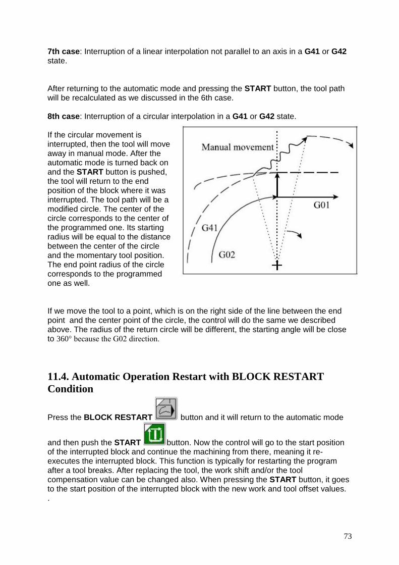
73
7th case: Interruption of a linear interpolation not parallel to an axis in a G41 or G42 state. After returning to the automatic mode and pressing the START button, the tool path will be recalculated as we discussed in the 6th case. 8th case: Interruption of a circular interpolation in a G41 or G42 state. If the circular movement is interrupted, then the tool will move away in manual mode. After the automatic mode is turned back on and the START button is pushed, the tool will return to the end position of the block where it was interrupted. The tool path will be a modified circle. The center of the circle corresponds to the center of the programmed one. Its starting radius will be equal to the distance between the center of the circle and the momentary tool position. The end point radius of the circle corresponds to the programmed one as well. If we move the tool to a point, which is on the right side of the line between the end point and the center point of the circle, the control will do the same we described above. The radius of the return circle will be different, the starting angle will be close to 360° because the G02 direction.
11.4. Automatic Operation Restart with BLOCK RESTART
Condition
Press the BLOCK RESTART button and it will return to the automatic mode
and then push the START button. Now the control will go to the start position of the interrupted block and continue the machining from there, meaning it re-executes the interrupted block. This function is typically for restarting the program after a tool breaks. After replacing the tool, the work shift and/or the tool compensation value can be changed also. When pressing the START button, it goes to the start position of the interrupted block with the new work and tool offset values. .
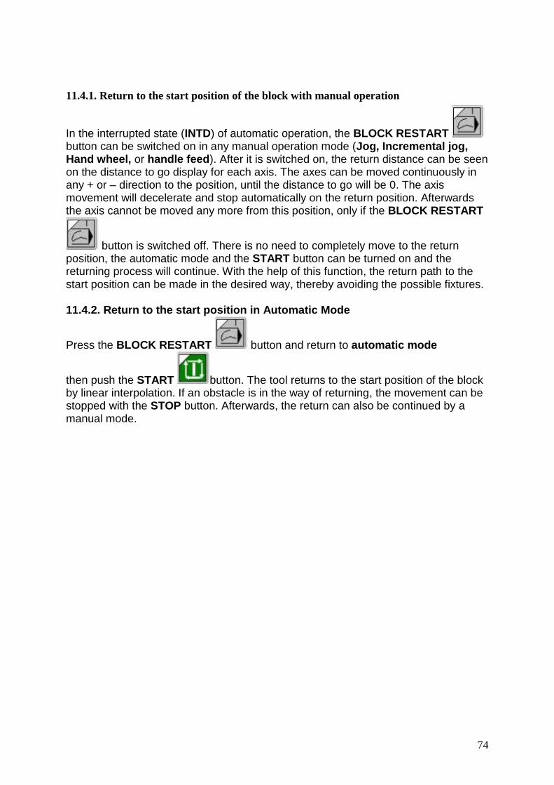
74
11.4.1. Return to the start position of the block with manual operation
In the interrupted state (INTD) of automatic operation, the BLOCK RESTART button can be switched on in any manual operation mode (Jog, Incremental jog, Hand wheel, or handle feed). After it is switched on, the return distance can be seen on the distance to go display for each axis. The axes can be moved continuously in any + or – direction to the position, until the distance to go will be 0. The axis movement will decelerate and stop automatically on the return position. Afterwards the axis cannot be moved any more from this position, only if the BLOCK RESTART
button is switched off. There is no need to completely move to the return position, the automatic mode and the START button can be turned on and the returning process will continue. With the help of this function, the return path to the start position can be made in the desired way, thereby avoiding the possible fixtures. 11.4.2. Return to the start position in Automatic Mode
Press the BLOCK RESTART button and return to automatic mode
then push the START button. The tool returns to the start position of the block by linear interpolation. If an obstacle is in the way of returning, the movement can be stopped with the STOP button. Afterwards, the return can also be continued by a manual mode.

75
11.4.3. Different return moves while the BLOCK RESTART is active.
The examples below are meant to show how to return to the start position of an interrupted block that has a movement command. 1st case: The control is in the G40 state and the block is interrupted and restarts a linear interpolation. The graphic on the right shows how a linear interpolation in the X, Y plane is interrupted. This requires the manual mode to be set and a manual operation is used along all three axes. Then the automatic mode is turned back on and the
BLOCK RESTART button is switched on. The START button is pressed and the control returns to the start position of the block.
The same exact thing will occur if the BLOCK RESTART button is on and we use one of the manual modes. During the return process, all the axes are moving, even those which are not programmed in the interrupted block. The return movement will add or subtract all the offset modifications that might be used. The graphic on the right shows how no movement was programmed in the Z direction in the interrupted block. A similar scenario can occur when using a drilling cycle instead a linear interpolation. Let us examine the following drilling cycle: ... G0 X50 Y20 Z10 G17 G90 G81 X100 Y70 Z–60 R2 F200
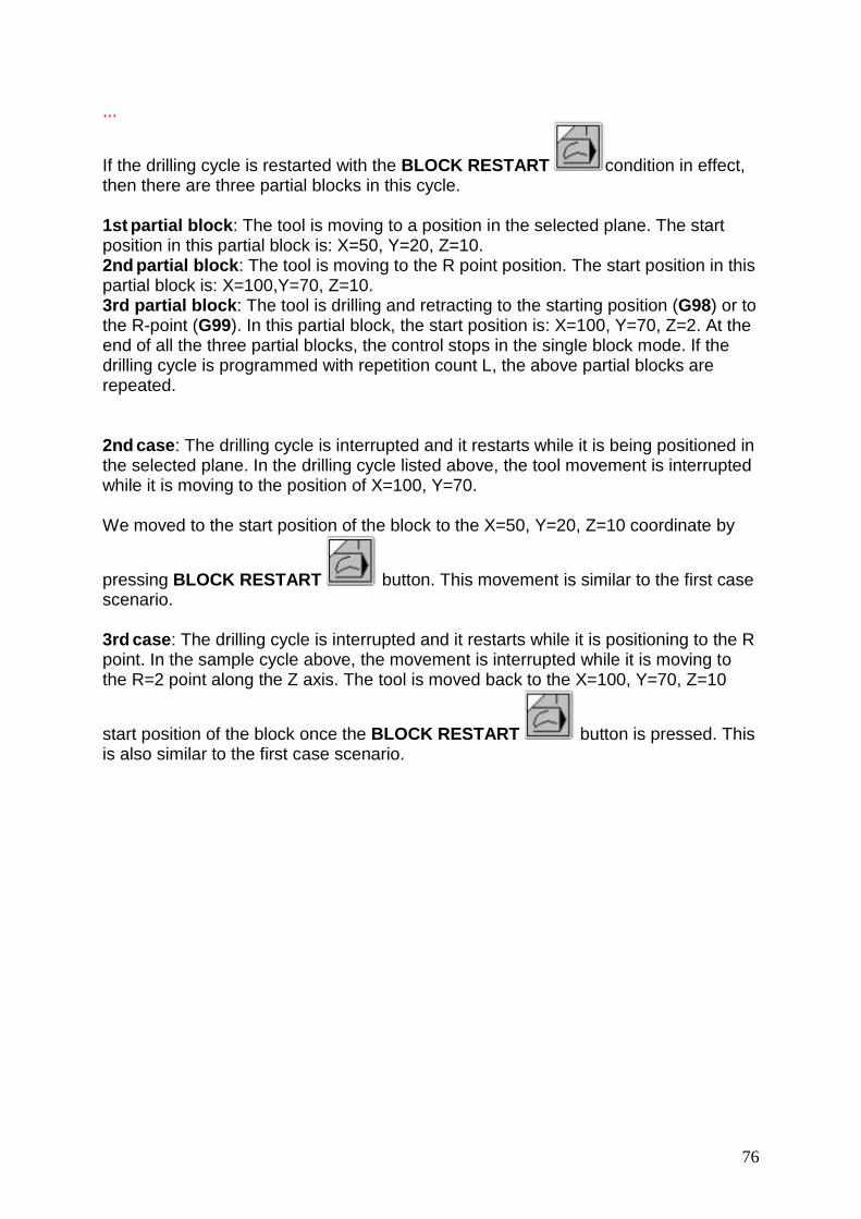
76
...
If the drilling cycle is restarted with the BLOCK RESTART condition in effect, then there are three partial blocks in this cycle. 1st partial block: The tool is moving to a position in the selected plane. The start position in this partial block is: X=50, Y=20, Z=10. 2nd partial block: The tool is moving to the R point position. The start position in this partial block is: X=100,Y=70, Z=10. 3rd partial block: The tool is drilling and retracting to the starting position (G98) or to the R-point (G99). In this partial block, the start position is: X=100, Y=70, Z=2. At the end of all the three partial blocks, the control stops in the single block mode. If the drilling cycle is programmed with repetition count L, the above partial blocks are repeated. 2nd case: The drilling cycle is interrupted and it restarts while it is being positioned in the selected plane. In the drilling cycle listed above, the tool movement is interrupted while it is moving to the position of X=100, Y=70. We moved to the start position of the block to the X=50, Y=20, Z=10 coordinate by
pressing BLOCK RESTART button. This movement is similar to the first case scenario. 3rd case: The drilling cycle is interrupted and it restarts while it is positioning to the R point. In the sample cycle above, the movement is interrupted while it is moving to the R=2 point along the Z axis. The tool is moved back to the X=100, Y=70, Z=10
start position of the block once the BLOCK RESTART button is pressed. This is also similar to the first case scenario.

77
4th case: The drilling cycle is interrupted and it restarts during the drilling operation. The tool is moved back to the X=100, Y=70, Z=2 starting position of the block when you press the BLOCK
RESTART button. If you press the START button, the tool will re-execute the drilling and the retraction. A similar scenario can occur when the cutter compensation is valid and the block is interrupted and it returns to its starting position. In the cases below, the cutter compensation is on and all axes are in the selected plane. If the movements are out of the selected plane, the cases which are described in the G40 state can be applied. 5th case: The tool returns to the start position of the block after the machining was interrupted in offset mode and the tool was at an outside corner. If you want to start the tool return, press the BLOCK RESTART
button. In this condition, the tool will start from the interrupted block. There will be the following calculation: the length of the offset vector will be multiplied by the length of the new corner radius of the tool, then the result will be divided by the length of the old corner radius.
Afterwards, the machining is continued on the tool path with the new offset value. During the start point return, all the axes will return to the starting point. The tool will move also in the Z direction if any manual movement has been made in this direction. If the tool length was also modified after the tool was replaced, the new registered tool offset will be taken into account during the return movement (see the 1st case).
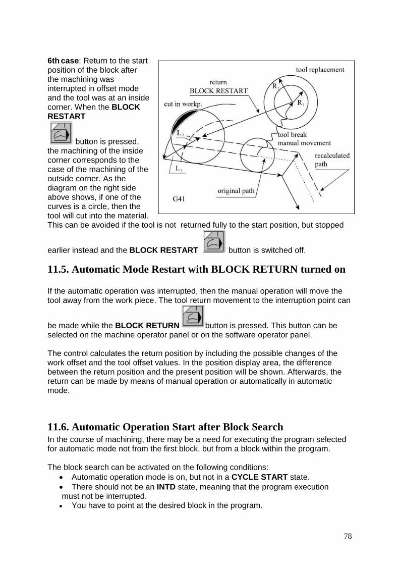
78
6th case: Return to the start position of the block after the machining was interrupted in offset mode and the tool was at an inside corner. When the BLOCK RESTART
button is pressed, the machining of the inside corner corresponds to the case of the machining of the outside corner. As the diagram on the right side above shows, if one of the curves is a circle, then the tool will cut into the material. This can be avoided if the tool is not returned fully to the start position, but stopped
earlier instead and the BLOCK RESTART button is switched off.
11.5. Automatic Mode Restart with BLOCK RETURN turned on If the automatic operation was interrupted, then the manual operation will move the tool away from the work piece. The tool return movement to the interruption point can
be made while the BLOCK RETURN button is pressed. This button can be selected on the machine operator panel or on the software operator panel. The control calculates the return position by including the possible changes of the work offset and the tool offset values. In the position display area, the difference between the return position and the present position will be shown. Afterwards, the return can be made by means of manual operation or automatically in automatic mode.
11.6. Automatic Operation Start after Block Search In the course of machining, there may be a need for executing the program selected for automatic mode not from the first block, but from a block within the program. The block search can be activated on the following conditions:
Automatic operation mode is on, but not in a CYCLE START state.
There should not be an INTD state, meaning that the program execution must not be interrupted. You have to point at the desired block in the program.
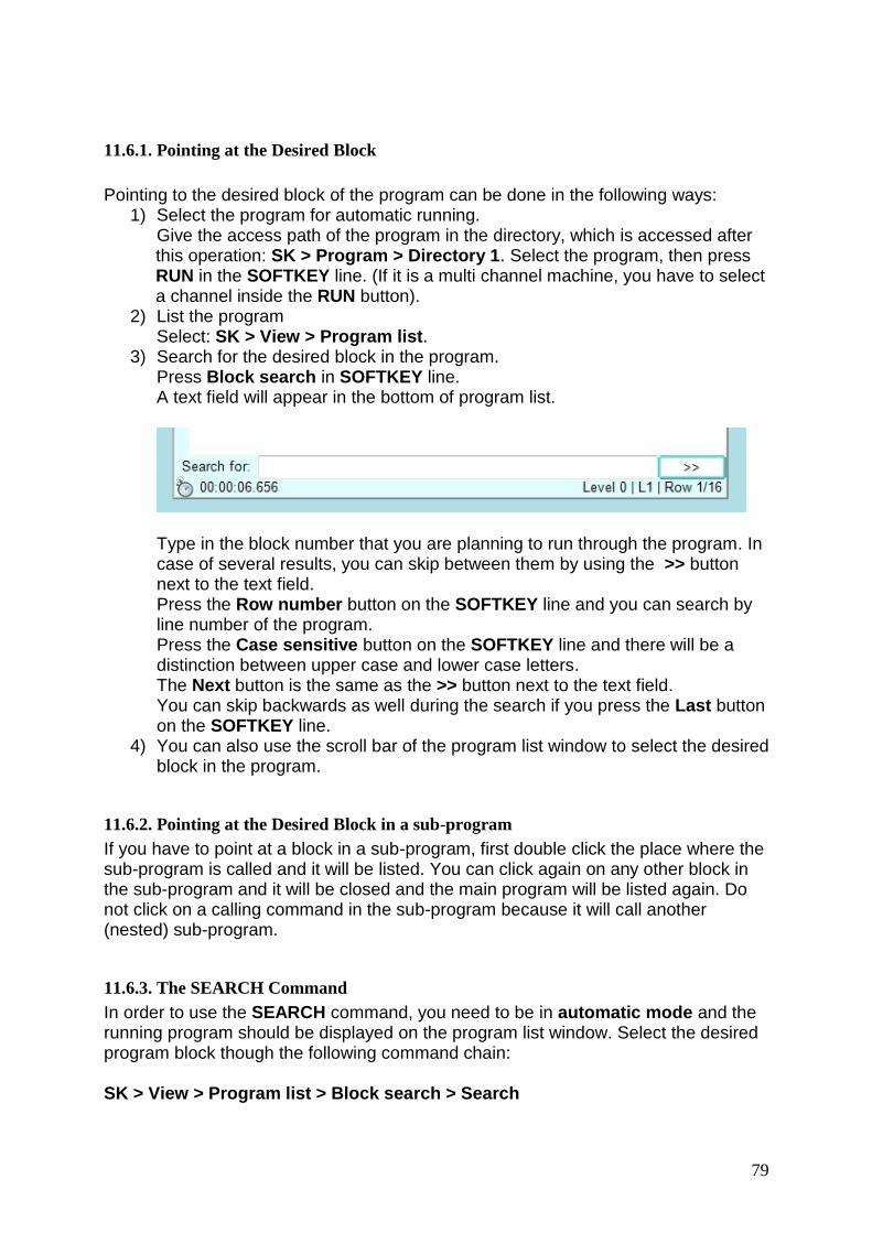
79
11.6.1. Pointing at the Desired Block
Pointing to the desired block of the program can be done in the following ways:
1) Select the program for automatic running. Give the access path of the program in the directory, which is accessed after this operation: SK > Program > Directory 1. Select the program, then press RUN in the SOFTKEY line. (If it is a multi channel machine, you have to select a channel inside the RUN button).
2) List the program Select: SK > View > Program list.
3) Search for the desired block in the program. Press Block search in SOFTKEY line. A text field will appear in the bottom of program list.
Type in the block number that you are planning to run through the program. In case of several results, you can skip between them by using the >> button next to the text field. Press the Row number button on the SOFTKEY line and you can search by line number of the program. Press the Case sensitive button on the SOFTKEY line and there will be a distinction between upper case and lower case letters. The Next button is the same as the >> button next to the text field. You can skip backwards as well during the search if you press the Last button on the SOFTKEY line.
4) You can also use the scroll bar of the program list window to select the desired block in the program.
11.6.2. Pointing at the Desired Block in a sub-program
If you have to point at a block in a sub-program, first double click the place where the sub-program is called and it will be listed. You can click again on any other block in the sub-program and it will be closed and the main program will be listed again. Do not click on a calling command in the sub-program because it will call another (nested) sub-program.
11.6.3. The SEARCH Command
In order to use the SEARCH command, you need to be in automatic mode and the running program should be displayed on the program list window. Select the desired program block though the following command chain: SK > View > Program list > Block search > Search

80
The control will collect all the information in a table below the program list, which will represent all of the commands made since the beginning of the program. The message SEARCH will be displayed in the status field, showing that a block has been searched. Let us examine a fragment of the following part program: N010 G54 G15 G17 G40 G49 G80 G90 T1 N020 G0 X150 Y0 B90 M6 N030 T2 N040 G43 Z-5 H1 S500 M11 M3 M8 N050 G1 X-100 F200 N060 Y50 N070 X100 N080 Y100 N090 X-100 N100 G0 Z5 M5 M9 N110 X150 Y0 M6 N120 T3 N130 G43 Z-10 H2 S1000 M12 M3 M8 N140 G1 G42 X100 F300 N150 Y100 N160 X0 … Start the block search for the N150 block. In this case, the control collects the information you see in the green-tinted window. The selected tool number: T2. The M6 command is programmed in the N110 block, which made the tool change specified in the N030 block. Therefore, upon pressing the START button, the T2 tool will be searched in the tool magazine. Tool change: M6 After preparing the T2 tool, the tool will change because the M6 command is programmed in the N100 block.

81
Tool to be Prepared: T3 The T3 tool is programmed in the N120 block. In this case, the search for the T3 can be done while the T2 is still working. The above example illustrates how the data referring to the tool change is gathered. The tool change is done by means of the M6 command in the machine. If the tool change is done simply with the function T, it will only gather the last code in the block. The method of gathering data referring to tool change can be specified in the parameter 1338 M06 (Program/Block Nr Search). If the value of this parameter is 1, it executes the data gathering according to the M06 function.
Attention! You have the following program section: T1
M6 T2 When using the M6 command in the 2nd block, the tool will be changed. If you wish to program the tool preparation only, then program the T code in a block, which has no M6 command. The correct version for this is shown below: T1 M6 or T1 T2 M6 T2
Spindle Gear Range Code: M12 In the N150 block, the gear range M12 code is valid because it was programmed earlier in the N130 block. This code will be active. Spindle Revolution Code: S1000 In the N150 block, the spindle speed S1000 command is valid because it was programmed in the N130 block. This code will be active. Spindle Rotation Code: M3 This command refers to the last spindle rotation code that is gathered when the M3 command is programmed in the N130 block. Coolant On Code: M8 This command refers to the last spindle rotation code that is gathered when the M8 command is programmed in the N130 block.

82
Other Functions: M50, M51 Other M functions are listed in a separate line. In the sample program, the table has been rotated to the B90 position, which was programmed in the N010 block. For the table rotation, the O9031 macro is called. The following program section can be found in the macro: %O9031(TABLE ROTATION) ... M50 G0 B#196 M51 ... M99 %
Since the table has Hirth toothed clamping, it must be unclamped before rotation by using the M50 function. It must also be clamped after the rotation by using the M51 function. In the course of a block search the control also reads the macros and gathers the information needed from there.
Note: In the NCT 200 control family, even the user can define M-code groups. If there is a group which includes the M50 and the M51 commands, the search will be made in the following way: the last M code will be searched (which is in this group) and was programmed in the last block, prior the search. For details about M code group definition please refer to the description of the parameter. Positions The gathered positions are absolute values and the slides will go to those positions after the CYCLE START button is pushed. . The N130 block is a milling operation of G1 linear movement parallel to the Y axis on the X100 coordinate from Y0 to Y100. This block is pointed at during the course of the block search, meaning that this will be the first block to be executed by control after the block search. Therefore, before executing N130 block, the control goes to the position of the X100, Y0, Z–10 coordinate. The situation is the same in case of other interpolation (G2, G3, G33) movements, meaning that the table shows the starting position of the selected block. If the selected block contains rapid traverse positioning (G0, block), the positions of the table will show the end position of the selected block. If a drilling cycle is selected, the same positions will point to the end position in the selected plane. Afterwards, the operator has to decide the proper order so that the control unit can reach the necessary conditions.

83
START Without Intervention If the operator presses the START button without any manual operation, the control will reach the necessary conditions in the following order: – First, it executes the selected functions according to their order in the table (i.e. in this case: T2, M6, T3, M12, S1000, M3, M8, M50, M51). – Second, it executes the positioning on the axes which have a custom macro command appointed to them. In this case, it will move on axis B because it will generate a macro call once the move is finished. – Finally, the tool positions itself along all axes at the same time. This positioning will be a rapid traverse movement and the rapid speed will stop 1000 increments (measured along the vectors) before the end position. The rest of the distance will be made by the programmed feed rate.

84
Manual Operation Intervention Before START If a manual operation mode (jog, incremental jog, or manual handle feed) is selected before pressing the START button, then the distance / distance to go can be moved manually. It is similar to how we've described the BLOCK RESTART and the BLOCK RETURN conditions. There is no need to fully return to the searched position because the process can be continued by switching over to the automatic mode and pressing the START button instead. Afterwards, the order of the execution of the function corresponds to the methods discussed previously. The position calculated in the course of a block search is done in a way that will avoid hitting any possible obstacles.
Note: By stepping into another operation mode (like: MDI), the BLOCK SEARCH state will be canceled by the control and you will have to repeat the search again.

85
Other Intervention Possibilities Before START It is possible to change the order of execution, and cancel the execution of other M -codes before starting the execution of data gathered in automatic mode. Touch one of the functions or coordinates (which should be taken out of the execution after the first START button is pressed) and the display's background will turn from green to yellow. If you touch this field several times, the colors will alternate in cycle. When the START button is pressed, the yellow commands are not executed, only those which are not taken out of the execution (green background). After the selected commands (the green ones) are executed, the control assumes the STOP state and displays the commands in green, which are not executed in the first cycle. The above selection can be repeated several times. Some of the other gathered M functions can be canceled. In this case, double click the function to be cleared and it will turn red. Press the START button and it will not be not executed, nor will it get cancelled either. Next time it will appear in red again. By touching them once, they will turn green, so next time they can be executed. The process begins again if you press the START button again.
Note: Positioning, tool changes and spindle commands cannot be canceled. This process can be continued until all the gathered commands are executed. Then even the red commands, which are assigned to be cancelled, will disappear and the execution will continue according the usual automatic mode. In the above example on page 82, the M3 command can be taken out from the first execution cycle, as well as the movement Z-10. This way, we can prevent the tool from crashing during positioning. After pressing the START button, all functions except the spindle rpm start and the Z positioning, are executed. If the START button is pressed again, the spindle rpm will start and the tool will move to the work piece in Z-direction. Two other functions were gathered: M50 table unclamp and M51 table clamp. As we mentioned before, the control also reads the macro O9031. There is the B movement command in there. The table unclamps and clamp commands are necessary to be carried out, which are commanded inside the macro. Obviously in this case the execution of the M50 and M51 commands is useless, therefore it can be canceled. It is always the operator’s responsibility to decide which functions are worth saving and which ones can be erased.

86
11.6.4. The GOTO Command
If you point to the desired block and press the GOTO key, the control will execute the program from the selected block after you press the START button. Contrary to the SEARCH command, it does not gather functions and positions from the beginning of program. It is the operator’s duty to place the machine in the appropriate state and position. The effect of the GOTO command is the same as if we would command a GOTOn (n is the block number) at the beginning of the program.
11.6.5. Giving a Repetition Number
If the program has a subprogram call and you wish to search for a block in the subprogram, it is possible to tell how many times the subprogram can run when you press the START button. When you use a SEARCH or GOTO command for a block in the subprogram, a window will show up to display the multi level sub-program call. Next to all levels, you can find an Lx expression, where the x is the number of the repetitions. In each level, you will find the access path to the sub-programs and its name. Next to the Row label, you can find the number where the subprogram was called. On the lowest level, you can see the number of the block you wish to find. Next to the Lmax label, you can see how many times the sub-program would run normally. You cannot call the sub-program more times than this number when you use the block search. In order to set the repetition for a sub-program, select a level then set how many times the sub-program shall be called, using either the L++ or the L- - buttons. You can find the number of the current level in a window at the bottom of the display. Here, you can also set how many more times the sub-program can be repeated by using the number scale. You cannot assign a similar repetition number like that to the main program. In the SOFTKEY line, the SEARCH/GOTO buttons can be found again. After giving the repetition number, you can finalize its settings. The remaining tasks are the same as those described in the command GOTO and command SEARCH chapters.

87
12. Settings
12.1. The Sound of KEY CLICKS
12.1.1. KEY CLICK Sounds of the Operating System
In the SETTING mode, you can turn the key clicks sounds (generated by the operating system) on and off. If it is turned on, even the keyboard connected to USB connection will give a click sound when a button is pressed. In order to turn the sounds on and off, follow the steps below. 1. Turn on the Emergency Stop button and EMG will show up in the status field. 2. Use the following command chain: SK > Shut down. 3. The Shutdown menu will be displayed. Press OK and the Windows Explorer
screen will appear. 4. By touching the bottom part of the screen, the START menu of the operating
system will come up. Choose Settings > Control Panel and double click on the Volume & Sounds icon and its setup panel will show up.
5. Under the line Enable clicks and taps, you can find the Key Clicks box with a checkmark inside of it. If you press the box, you can enable or disable the key click sounds.
12.1.2. KEY CLICK Sounds from the CNC system.
In order to turn the sounds from the CNC system on and off, follow the steps below.
1. In the right side of the SOFTKEY column, touch the Win-s icon. 2. A new display will pop up. Touch the last icon in the lower row: Prog.settings
- NCT User. 3. Select the Keyboard menu and on the machine operator panel, check the
Enable Beep box. You can select the beep for the USB keyboard also. 4. If you uncheck the Enable Beep box, the key click will stop giving sound.

88
12.2. Program settings In order to modify the program settings, use the following command chain. SK > Settings > Prog. settings The Prog. setting – NCT user window will pop up. Here, you can set the colors, resolutions, language, network, time and other functions of the control panel. In the header of the window, you can find following tabs: - Styles: Setting up the styles of the control panel. - Keyboard: Setting of the USB keyboard and the machine operator panel. - Display: Setting of the display resolution and screen visualization. - Date/Time: Setting the date and time, as well as registry settings. - Memory: Displays the current amount of free and used memory. - IP: Allows you to modify the network setting. - System: Determines the frequency of various system backups.
12.2.1. Style adjustment
SK > Settings > Prog. settings > Styles
You have a choice between three basic colors: Brown, Blue and Gray. Select the adequate color tab. On the right side of this window, you can see the different buttons, text background colors, sign layouts and pictograms in the style that you have chosen.

89
Save changes: You do not have to press any button for savings, these settings will become valid immediately.
12.2.2. The Sound of Error Messages
SK > Settings > Prog.setting > Keyboard You can see three setting fields separated by the frames.
In the top Error message sound field, you can enable or disable the sounds of the error messages. You can set the sound volume by using the volume control slide.

90
12.2.3. The Language of the USB keyboard
In the middle USB keyboard field, you can set the language for a keyboard connected to the USB connector. You can enable or disable the beep of the keyboard click by checking the Enable Beep window.
12.2.4. Which keyboard is active?
The bottom Machine operator panel field is used to select the active keyboard. Only a single keyboard can activated at one time: either the physical or the software. If you have the first configuration, like the one on the left side, you can select whether you wish to use a physical or a software machine operator panel. The second configuration only allows you to use the software operator's panel. 1. Configuration: 2. Configuration:

91
You can enable or disable the beep of the keyboard click by checking the Enable Beep window.
Save changes: To validate the changes you have made, press the OK button in the right corner of the window.

92
12.2.5. Freezing the windows
SK > Setting > Prog.setting > Display The Display settings allow you to determine the window size and the location of multiple windows that are visible on the monitor panel. If you want to freeze all of the windows, check the All windows freezing box in the Visualization section of the Display tab. When a window is frozen, the size button in the upper right hand corner of the window will turn grey or disappear. In that case, none of the windows can be moved or resized. Once it is frozen, you can double click on the header of the window to maximize it and fill up the full screen of control monitor. .
Freezing can be done in two ways: - You can freeze all windows by clicking the All windows freezing box. - If you wish to freeze only a single window out of group, then check the Saved windows freezing box. If you need to save a list of frozen windows, do the following: Open the window you wish to freeze and set them to the adequate size and place.
In the sidebar, select the Win-s Softkey, then select the icon in the pop up window. The List of windows - NCTuser window will pop up, where you can find a list of the previously opened windows. In the lower Softkey line, select the Save Windows tab.

93
Save changes: To keep the changes you just made, press OK on the Prog.settings – NCTuser window.

94
12.2.6. Setting the Help Text
Besides the printed version of the operation manual, the help text can be also reached from the control panel through the following command chain: SK > Mix > Operator's help Additional help for the parameter description is possible also: SK > Service > Params > Help The languages of the help text can be set on the display tab. The set language for the help is independent from the basic user language of the CNC control. You can set the help text through the following command chain: SK > Setting > Prog.setting > Display tab (use the Help language window and scroll down to the language of your choice)
Save changes: To keep the changes, press OK in the lower right corner of the window.

95
12.2.7. Calibration of the Touch screen
1. SK > Setting > Prog.setting 2. In the window, select the Display tab
3. Press the blue Touch Calibration button. 4. A new menu will then pop up: TUB1: channel. 5. You can now choose calibration on either 4 points or 25 points. 6. Once a calibration point number has been chosen, touch the flashing red X
appearing on the screen until you hear a sound. The flashing will then stop and the X will turn green. Once every cross has turned green, the menu will appear again. This used to determine the accuracy of the calibration.
7. Select Exit to quit the calibration.

96
12.2.8. Setting the Resolution of the Screen
SK > Setting > Prog.setting > Display .
. In the bottom field of the window, you can find the possible screen resolution options. The already selected resolution will be displayed next to Current resolution. If you need to resize the screen or pick a different resolution, simply select any of the other boxes that contain the desired resolution. You can also select the size of the screen. You will need a full-authorization access for modifying the resolution.
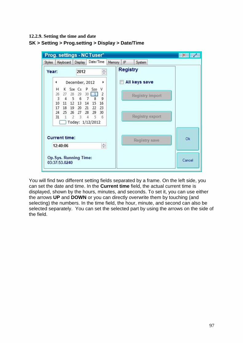
97
12.2.9. Setting the time and date
SK > Setting > Prog.setting > Display > Date/Time
You will find two different setting fields separated by a frame. On the left side, you can set the date and time. In the Current time field, the actual current time is displayed, shown by the hours, minutes, and seconds. To set it, you can use either the arrows UP and DOWN or you can directly overwrite them by touching (and selecting) the numbers. In the time field, the hour, minute, and second can also be selected separately. You can set the selected part by using the arrows on the side of the field.

98
13. CHANNELS
One of the most important strengths of the NCT 2xx is the support of the multi-channel control unit. The maximum number of the channel is 8, but it may be different depending on the software version that is being used. The several channels mean several logical CNC controls in one physical unit. Every channel is a separate CNC control, executing its own technological program, and it fully capable of being adjusted independent of the all other channels. For each channel, you will find a separate tool correction and zero point tables, a macro variables table, a time and part counter, a position display, a single block window, program list and an FST window. Here are the most common switches that modify the program execution in each separate channel: single block execution, optional block skip, optional stop, program test, machine lock function, dry run, block return, block repeat, and MST functions locked. In case of a multichannel machine, the following addendums are needed for the operation:
13.1. Handling of the Windows The content of certain windows depend on the channel, so a certain window can belong to every channel. For example, each channel has its own position display. In the header of such windows, you can see the number of the channel, which is related to the content of the window. It is possible to display multiple windows at the same time, in different channels.
13.2. Position display of channels On an NCT 2xx control unit that is connected to a multichannel machine, you will be able to collect positions, coordinates and other data, channel by channel in a separate window.
1) Windows can be called by the Position button in SOFTKEY line. The position windows of those channels will appear and the channel number will be found in the 4th field of the first line of the status display.
2) Press New window in the SOFTKEY line. A new window will appear, possibly
hiding the old one, but still containing the exact same content.
3) Press the CH ++ button in the bottom of the sidebar. 4) The content of a new open window will change to the content of the next
channel. 5) Grab this window by its header and the new window can be put next to the old
one, so that you can see the position of the two channels at the same time.

99
6) You can select different windows to display the content of the different channels by selecting the CH++ button. We can show many more position display windows by adding New window.
7) Other windows are dependant on different channels and can be displayed at the same time.
13.3. The START button On an NCT 2xx control unit that is connected to a multichannel machine, there is only one START button. Once pressed, all the channels in automatic operation mode will start but only those that have a valid part program.
13.4. STOP button When you press the STOP button, all the feed movements will stop and all the channels in automatic operation mode will go to a STOP state.
13.5. Multi-channel Program Execution in Automatic Operation
Mode After having created several part programs, you have to select them for automatic execution by picking a program for each channel. It is very similar to the basic operation with one channel control.
1. To select the first program to run, use the following command chain: SK >
Program > Directory1 (or Directory2). A directory will then appear. 2. Select the program you wish to run, then select Run /AUTO on the
SOFTKEY line and the channel of the machine will appear. 3. Select the channel on which you wish to run the given program. 4. The program will be loaded to the automatic execution storage on the
given channel. At the end of the status bar of the channel that you have chosen, the name and the access way of the program will appear.
5. In the SOFTKEY line, the channel's number won’t disappear and the same
program can be designated for other channels. ***
6. Set the other programs to the selected channels.
7. Press the Auto Operation Mode button in any of the channels that you wish to run.
8. Upon pressing the Cycles Start button, the program execution will start on all channels in automatic operation mode which contain valid part programs.
***: Note: There is no guarantee that running two totally equal programs on two
different channels will both end at the same time.

100
13.6. Operation Mode Change You can define different operation modes for each channel. In the basic state, when you press an operation button, all the channels will get the same operation mode. It is mainly defined by the machine tool builder. If you press a channel selection button and an operation mode selection button at the same time, it is common for only the selected channel to take the operation mode. For the exact use of your machine, please contact the machine tool builder.