Embed Size (px)
Citation preview

ControlNet-to-DeviceNet Linking Device1788-CN2DN
User Manual
Important User Information Because of the variety of uses for the products described in this publication, those responsible for the application and use of this control equipment must satisfy themselves that all necessary steps have been taken to assure that each application and use meets all performance and safety requirements, including any applicable laws, regulations, codes and standards.
The illustrations, charts, sample programs and layout examples shown in this guide are intended solely for purposes of example. Since there are many variables and requirements associated with any particular installation, Allen-Bradley does not assume responsibility or liability (to include intellectual property liability) for actual use based upon the examples shown in this publication.
Allen-Bradley publication SGI-1.1, Safety Guidelines for the Application, Installation and Maintenance of Solid-State Control (available from your local Allen-Bradley office), describes some important differences between solid-state equipment and electromechanical devices that should be taken into consideration when applying products such as those described in this publication.
Reproduction of the contents of this copyrighted publication, in whole or part, without written permission of Rockwell Automation, is prohibited.

Throughout this manual we use these notes to make you aware of safety considerations:
Warning and Attention statements help you to:
• identify a hazard
• avoid a hazard
• recognize the consequences
Allen-Bradley, ControlLogix, PLC-5, and SLC 500 are trademarks of Rockwell Automation.
DeviceNet is a trademark of Open Device Vendors Association (ODVA), Inc.
ControlNet is a trademark of ControlNet International. Ltd.
RSLinx, RSNetWorx, RSLogix 5, and RSLogix 5000 are trademarks of Rockwell Software.
Windows NT is a trademark of Microsoft Corporation.
WARNING
!Identifies information about practices or circumstances that have the potential to create an explosion hazard.
ATTENTION
!Identifies information about practices or circumstances that can lead to personal injury or death, property damage or economic loss.
IMPORTANT Identifies information that is critical for successful application and understanding of the product.
European Communities (EC) Directive Compliance
If this product has the CE mark it is approved for installation within the European Union and EEA regions. It has been designed and tested to meet the following directives.
EMC Directive
This product is tested to meet the Council Directive 89/336/EC Electromagnetic Compatibility (EMC) by applying the following standards, in whole or in part, documented in a technical construction file:
• EN 50081-2 EMC — Generic Emission Standard, Part 2 — Industrial Environment
• EN 50082-2 EMC — Generic Immunity Standard, Part 2 — Industrial Environment
This product is intended for use in an industrial environment.
Low Voltage Directive
This product is tested to meet Council Directive 73/23/EEC Low Voltage, by applying the safety requirements of EN 61131-2 Programmable Controllers, Part 2 - Equipment Requirements and Tests. For specific information required by EN 61131-2, see the appropriate sections in this publication, as well as the Allen-Bradley publication Industrial Automation Wiring and Grounding Guidelines, publication 1770-4.1.
Open style devices must be provided with environmental and safety protection by proper mounting in enclosures designed for specific application conditions. See NEMA Standards publication 250 and IEC publication 529, as applicable, for explanations of the degrees of protection provided by different types of enclosure.

Rockwell Automation Support
Rockwell Automation offers support services worldwide, with over 75 sales/support offices, 512 authorized distributors and 260 authorized systems integrators located throughout the United States alone, as well as Rockwell Automation representatives in every major country in the world.
Local Product Support
Contact your local Rockwell Automation representative for:
• sales and order support
• product technical training
• warranty support
• support service agreements
Technical Product Assistance
If you need to contact Rockwell Automation for technical assistance, call your local Rockwell Automation representative, or call Rockwell directly at: 1 440 646-5800.
For presales support, call 1 440 646-3NET.
You can also obtain technical assistance online from the following Rockwell Automation WEB sites:
• www.ab.com/mem/technotes/kbhome.html (knowledge base)
• www.ab.com/networks/eds (electronic data sheets)
Your Questions or Comments on this Manual
If you find a problem with this manual, please notify us of it on the enclosed Publication Problem Report.

Preface
About This User Manual
What this Preface Contains This preface describes how to use this manual. The following table describes what this preface contains and where to find specific information.
Who Should UseThis Manual
This manual is intended for control engineers and technicians who are installing, configuring, and maintaining a ControlLogix, PLC-5, or SLC 500 based control system that links a DeviceNet network to a ControlNet network using a 1788-CN2DN linking device.
We assume you have a good understanding of ControlNet and DeviceNet, as well as familiarity with RSNetWorx software and application programming using RSLogix 5, RSLogix 500, or RSLogix 5000 software.
How To Use This Manual This manual describes how to install and configure the 1788-CN2DN linking device. It provides examples of ControlNet configurations with a ControlLogix processor, a PLC-5 processor, and a SLC 500 processor, and an example of configuring a DeviceNet network.
The example configurations are intended as guides to help you get your own system up and running. We recommend that you set up and perform the example configurations for the platforms you are working with and use them as building blocks for your own system.
Topic See pageWho Should Use This Manual P-1
How To Use This Manual P-1
About the Examples P-2
Common Techniques Used in This Manual P-2
System Components P-3
Where to Find More Information P-4
1 Publication 1788-UM053A-EN-P - July 2001
P-2 About This User Manual
About the Examples The examples presented in this manual are as follows:
• ControlNet ControlLogix configuration (chapter 3)
• ControlNet PLC-5 configuration (chapter 4)
• ControlNet SLC 500 configuration (chapter 5)
• DeviceNet configuration (chapter 6)
Common TechniquesUsed in This Manual
The following conventions are used throughout this manual:
• Bulleted lists provide information, not procedural steps.
• Numbered lists provide sequential steps.
• Information in bold contained within text identifies menu windows, or screen options, screen names and areas of the screen, such as dialog boxes, status bars, radio buttons and parameters.
TIP This symbol identifies helpful tips.
The screen captures shown in this manual are pictures of the software’s actual screens. The names of screen buttons and fields are generally in bold in the text of a procedure. Pictures of keys or icons represent the actual keys or icons you select.
Publication 1788-UM053A-EN-P - July 2001

About This User Manual P-3
System Components The following components were used for the examples shown in this manual. (See pages 1-1 to 1-2 for minimum system requirements.)
Quantity Product Name Catalog Number
1 ControlNet-to-DeviceNet Linking Device 1788-CN2DN
1 Personal computer with ControlNet communications card (1784-KTCx, 1784-PCIC, or 1784-PCICS) and driver
Any appropriate model running Windows NT 4.0, Service Pack 3 or higher, or Windows 2000
RSLinx Communications software,V2.30
9355-WABENE
RSNetworx for DeviceNet V3.00 and RSNetWorx for ControlNet V3.00 software
9357-ANETL3
For ControlLogix on ControlNet:
1 4-Slot ControlLogix chassis 1756-A4
1 ControlLogix power supply 1756-PA72
1 ControlLogix ControlNet Bridge Module 1756-CNB
1 Logix5550 controller 1756-L1
RSLogix 5000 software, V8.00 9324-RLD300ENE
For PLC-5 on ControlNet:
1 1771 Universal I/O Chassis 1771-A1B
1 1771 Power Supply 1771-P4S
1 PLC-5 ControlNet Processor 1785-L40C
RSLogix 5 software, V3.22 9324-RL5300ENE
For SLC 500 on ControlNet:
1 SLC 500 Modular Chassis 1746-A4/B
1 SLC Chassis power supply 1746-P1
1 SLC 500 ControlNet scanner 1747-SCNR
1 SLC 500 processor 1747-L542/B
RSLogix 500 software, V3.01 9324-RL0300ENE
For DeviceNet:
1 24V DC power supply Regulated 24V dc, 8A
1 RediStation 2705-T3DN1A42A-A
1 Series 9000 Photoeye 42GNU-9000
Associated ControlNet and DeviceNet media (taps, connectors, cable) as needed
Publication 1788-UM053A-EN-P - July 2001

P-4 About This User Manual
Where to Find More Information
Refer to the following Rockwell publications as needed for additional help when setting up your networks.
Many Rockwell publications are available online from the Automation Bookstore:
http://www.theautomationbookstore.com.
Rockwell Software products are provided with extensive tutorials and online Help. We recommend that you use the tutorials and Help menus to learn about these products.
For more information about Rockwell Software products, visit the Rockwell Software internet site:
http://www.software.rockwell.com.
For information about See this publication Publication number
ControlNet Media ControlNet Cable System, Planning and Installation Manual 1786-6.2.1
DeviceNet Media DeviceNet Cable System, Planning and Installation Manual DN-6.7.2-MAY99
Publication 1788-UM053A-EN-P - July 2001

Table of Contents
Chapter 1Module Description What This Chapter Contains . . . . . . . . . . . . . . . . . . . . . . . . . . 1-1
Product Overview . . . . . . . . . . . . . . . . . . . . . . . . . . . . . . . . . 1-1System Requirements . . . . . . . . . . . . . . . . . . . . . . . . . . . . . . . 1-1
Required Hardware. . . . . . . . . . . . . . . . . . . . . . . . . . . . . . 1-1Required Software . . . . . . . . . . . . . . . . . . . . . . . . . . . . . . 1-2Compatibility Information . . . . . . . . . . . . . . . . . . . . . . . . . 1-2
Hardware Description . . . . . . . . . . . . . . . . . . . . . . . . . . . . . . 1-2
Chapter 2Installing the 1788-CN2DN What This Chapter Contains . . . . . . . . . . . . . . . . . . . . . . . . . . 2-1
Precautionary Statements . . . . . . . . . . . . . . . . . . . . . . . . . . . . 2-1Installation Procedure. . . . . . . . . . . . . . . . . . . . . . . . . . . . . . . 2-2
Removing the CN2DN module . . . . . . . . . . . . . . . . . . . . . 2-3Connecting Power . . . . . . . . . . . . . . . . . . . . . . . . . . . . . . 2-3
ControlNet Connections . . . . . . . . . . . . . . . . . . . . . . . . . . . . . 2-5BNC Connectors . . . . . . . . . . . . . . . . . . . . . . . . . . . . . . . . 2-5Network Access Port (NAP). . . . . . . . . . . . . . . . . . . . . . . . 2-5
DeviceNet Connections . . . . . . . . . . . . . . . . . . . . . . . . . . . . . 2-7Setting the Node Address Switches . . . . . . . . . . . . . . . . . . . . . 2-8
CN2DN ControlNet Address . . . . . . . . . . . . . . . . . . . . . . . 2-8CN2DN DeviceNet Address . . . . . . . . . . . . . . . . . . . . . . . . 2-9
Setting the DNet Data Rate . . . . . . . . . . . . . . . . . . . . . . . . . . . 2-9Mounting Dimensions . . . . . . . . . . . . . . . . . . . . . . . . . . . . . 2-10
Chapter 3ControlLogix ControlNet Configuration
What This Chapter Contains . . . . . . . . . . . . . . . . . . . . . . . . . . 3-1RSLogix 5000 Configuration . . . . . . . . . . . . . . . . . . . . . . . . . . 3-2RSNetWorx for ControlNet Configuration. . . . . . . . . . . . . . . . . 3-6Viewing the CN2DN’s Input, Output, and Status Structures. . . . 3-9
Chapter 4PLC-5 ControlNet Configuration What This Chapter Contains . . . . . . . . . . . . . . . . . . . . . . . . . . 4-1
RSNetWorx for ControlNet Configuration. . . . . . . . . . . . . . . . . 4-1Viewing the CN2DN’s Input, Output, and Status Structures. . . . 4-7
Chapter 5SLC 500 ControlNet Configuration What This Chapter Contains . . . . . . . . . . . . . . . . . . . . . . . . . . 5-1
RSNetWorx for ControlNet Configuration. . . . . . . . . . . . . . . . . 5-1Viewing the CN2DN’s Input, Output, and Status Structures. . . . 5-6
Chapter 6RSNetWorx for DeviceNet Configuration
What This Chapter Contains . . . . . . . . . . . . . . . . . . . . . . . . . . 6-1Configuration Procedure. . . . . . . . . . . . . . . . . . . . . . . . . . . . . 6-1
i Publication 1788-UM053A-EN-P - July 2001

Table of Contents ii
Appendix ALED Status Indicators Module STATUS LED . . . . . . . . . . . . . . . . . . . . . . . . . . . . . . . A-1
Linking Activity LED. . . . . . . . . . . . . . . . . . . . . . . . . . . . . . . . A-2ControlNet Network Status LEDs (CNet A, CNet B) . . . . . . . . . A-2DeviceNet Network Status LED (including Slave Mode) . . . . . . A-3DeviceNet I/O Status LED. . . . . . . . . . . . . . . . . . . . . . . . . . . . A-3
Appendix B1788-CN2DN Input, Output, and Status Structures
Input Structure . . . . . . . . . . . . . . . . . . . . . . . . . . . . . . . . . . . . B-1Module Status Register Bit Definitions . . . . . . . . . . . . . . . . B-2
Output Structure . . . . . . . . . . . . . . . . . . . . . . . . . . . . . . . . . . B-2Module Command Register Bit Definitions . . . . . . . . . . . . . B-3
Status Structure . . . . . . . . . . . . . . . . . . . . . . . . . . . . . . . . . . . B-4Interpreting the Numeric Codes. . . . . . . . . . . . . . . . . . . . . B-5
Index
Publication 1788-UM053A-EN-P - July 2001

Chapter 1
Module Description
What This Chapter Contains The following table describes what this chapter contains and where to find specific information.
Product Overview The ControlNet-to-DeviceNet (CN2DN) linking device connects a ControlNet™ network to a DeviceNet™ network. The DeviceNet network typically consists of multiple devices, such as RediStation’s, photoeyes, etc. The ControlNet network consists of controllers, such as Logix™ or PLC-5™ processors, HMIs, drives, I/O devices, etc.
The CN2DN has two broad functions:
1. supporting closed-loop control
2. configuration and monitoring
The CN2DN maintains internal input, output, and status structures to reduce the complexity of connecting DeviceNet I/O and status data with ladder programs and to make diagnostic information available to the user. For more information on these structures see Appendix B.
System Requirements You need the following hardware and software components to use the 1788-CN2DN linking device. These components are required irrespective of the platform (e.g., ControlLogix, PLC-5, SLC 500) you are using.
Required Hardware
• ControlNet-to-DeviceNet linking device
• PC access to ControlNet through RSLinx™
• ControlNet and DeviceNet cabling
Topic See pageProduct Overview 1-1
System Requirements 1-1
Hardware Description 1-2
1 Publication 1788-UM053A-EN-P - July 2001
1-2 Module Description
Required Software
• Windows NT™ 4.0 with service pack 3 or higheror Windows 2000™
• RSLinx™ 2.10 or later; this is the communication software for the Allen-Bradley controller interfaces.
• RSNetWorx for ControlNet™ version 2.0 or later; this is the ControlNet configuration tool.
• RSNetWorx for DeviceNet™ version 2.11 or later; this is the DeviceNet configuration tool.
Compatibility Information
The 1788-CN2DN linking device is compatible with the DeviceNet and ControlNet specifications issued by the Open DeviceNet Vendor Association (ODVA), Inc. and ControlNet International, Ltd.
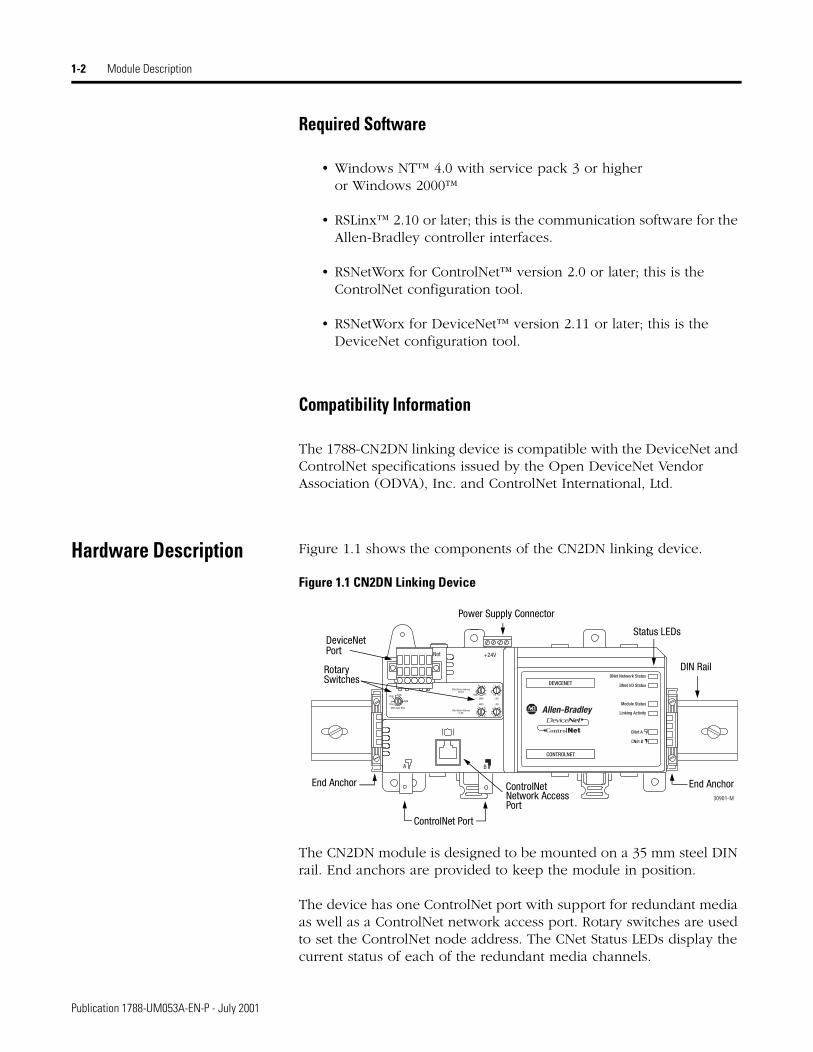
Hardware Description Figure 1.1 shows the components of the CN2DN linking device.
Figure 1.1 CN2DN Linking Device
The CN2DN module is designed to be mounted on a 35 mm steel DIN rail. End anchors are provided to keep the module in position.
The device has one ControlNet port with support for redundant media as well as a ControlNet network access port. Rotary switches are used to set the ControlNet node address. The CNet Status LEDs display the current status of each of the redundant media channels.
30901-M
Status LEDs
Power Supply Connector
ControlNet Port
Network AccessPort
DeviceNetPort
RotarySwitches
End Anchor End Anchor
DIN Rail
ControlNet
Publication 1788-UM053A-EN-P - July 2001

Module Description 1-3
The CN2DN has one DeviceNet port. Rotary switches are used to set the DeviceNet node address and the data rate. DNet LEDs display the current status of the network and the I/O channel.
Module Status and Linking Activity LEDs are provided. For information about the LEDs, see Appendix A.
The power supply connector is wired to 24V dc.
Publication 1788-UM053A-EN-P - July 2001

1-4 Module Description
Publication 1788-UM053A-EN-P - July 2001
Chapter 2
Installing the 1788-CN2DN
What This Chapter Contains Use this chapter as a guide when you install the 1788-CN2DN. This chapter covers the following topics:
.
Precautionary Statements We recommend that you adhere to this precautionary information.
Topic See page
Precautionary Statements 2-1
Installation Procedure 2-2
Removing the CN2DN module 2-3
Connecting Power 2-3
ControlNet Connections 2-5
BNC Connectors 2-5
Network Access Port (NAP) 2-5
DeviceNet Connections 2-7
Setting the Node Address Switches 2-8
CN2DN ControlNet Address 2-8
CN2DN DeviceNet Address 2-8
Setting the DNet Data Rate 2-9
Mounting Dimensions 2-10
WARNING
!If you connect or disconnect the ControlNet or DeviceNet cable with power applied to this module or any device on the respective network, an electrical arc can occur. This could cause an explosion in hazardous location installations. Be sure that power is removed or the area is nonhazardous before proceeding.
1 Publication 1788-UM053A-EN-P - July 2001

2-2 Installing the 1788-CN2DN
.
Because of the variety of uses for the product described in this publication, those responsible for the application and use of this control equipment must satisfy themselves that all necessary steps have been taken to assure that each application and use meets all performance and safety requirements, including any applicable laws, regulations, codes, and standards.
The illustrations, sample programs, and layout examples shown in this manual are intended solely for purposes of example. Since there are many variables and requirements associated with any particular installation, Allen-Bradley does not assume responsibility or liability (to include intellectual property liability) for actual use based upon the examples shown in this publication.
Installation Procedure The CN2DN module should be mounted on a standard 35 mm steel DIN rail. Follow the steps below to mount the CN2DN on the DIN rail.
1. Press the module straight onto the DIN rail at the desired location. Be sure that both latches snap into place.
Figure 2.1 - Mounting the CN2DN Module on the DIN Rail
ATTENTION
!This module contains ESD (Electrostatic Discharge) sensitive parts and assemblies. Static control precautions are required when installing or testing this assembly. Component damage may result if these procedures are not followed.
IMPORTANT You must use a steel DIN rail (A-B P/N 199-DR1 or equivalent) to meet the 1788-CN2DN’s vibration specifications. DO NOT use an aluminum DIN rail.
DIN Rail
CN2DN Module
PRESS ON
Wall or Support
Publication 1788-UM053A-EN-P - July 2001
Installing the 1788-CN2DN 2-3
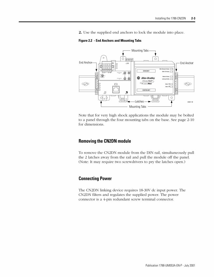
2. Use the supplied end anchors to lock the module into place.
Figure 2.2 - End Anchors and Mounting Tabs
Note that for very high shock applications the module may be bolted to a panel through the four mounting tabs on the base. See page 2-10 for dimensions.
Removing the CN2DN module
To remove the CN2DN module from the DIN rail, simultaneously pull the 2 latches away from the rail and pull the module off the panel. (Note: It may require two screwdrivers to pry the latches open.)
Connecting Power
The CN2DN linking device requires 18-30V dc input power. The CN2DN filters and regulates the supplied power. The power connector is a 4-pin redundant screw terminal connector.
30901-M
Mounting Tabs
Mounting Tabs
End Anchor
Latches
End Anchor
Publication 1788-UM053A-EN-P - July 2001

2-4 Installing the 1788-CN2DN
The pinout for the power connector is shown in Figure 2.3.
Figure 2.3 - Power Connector Pinout
Connect the primary power supply to the left + and - pair. The right + and - pair may be used to chain the primary power supply to downstream devices.
IMPORTANT No connection will be made to downstream devices unless the connector is plugged into the CN2DN.
30906-M
+ - + -
Publication 1788-UM053A-EN-P - July 2001
Installing the 1788-CN2DN 2-5
ControlNet Connections BNC Connectors
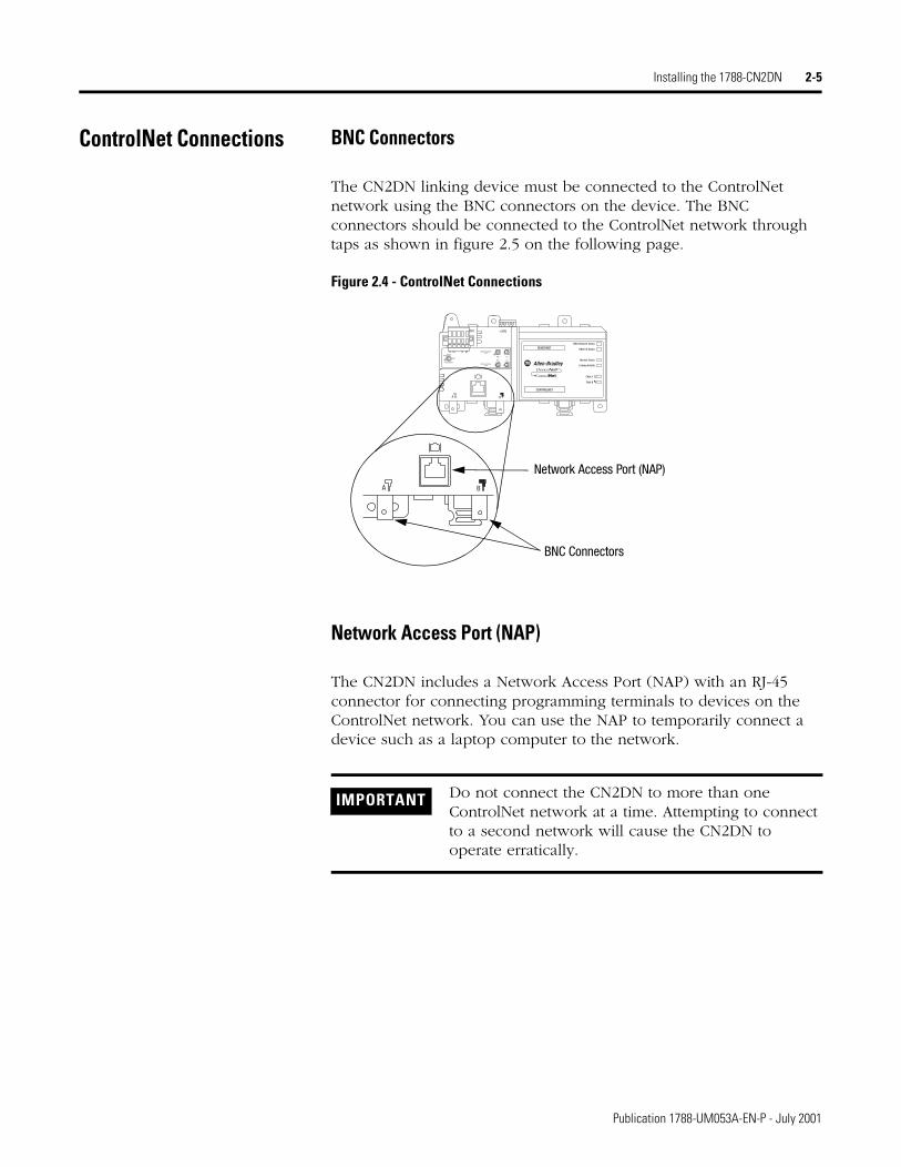
The CN2DN linking device must be connected to the ControlNet network using the BNC connectors on the device. The BNC connectors should be connected to the ControlNet network through taps as shown in figure 2.5 on the following page.
Figure 2.4 - ControlNet Connections
Network Access Port (NAP)
The CN2DN includes a Network Access Port (NAP) with an RJ-45 connector for connecting programming terminals to devices on the ControlNet network. You can use the NAP to temporarily connect a device such as a laptop computer to the network.
IMPORTANT Do not connect the CN2DN to more than one ControlNet network at a time. Attempting to connect to a second network will cause the CN2DN to operate erratically.
Network Access Port (NAP)
BNC Connectors
Publication 1788-UM053A-EN-P - July 2001

2-6 Installing the 1788-CN2DN
Figure 2.5 shows an example of a ControlNet network using redundant media.
Figure 2.5 - CN2DN on ControlNet (Redundant Media)
Refer to publication number 1786-6.2.1, ControlNet Cable System, Planning and Installation Manual, for further information.
ATTENTION
!When using redundant media, connect all channel A connectors to one cable, and all channel B connectors to the other cable.
If you connect the product to a cable system that does not support redundant media, connect the tap dropline to the BNC connector labeled channel A. Leave Channel B open when using single media.
30907-M
ControlNet DeviceLinkingDevice
Node 1
Node 2
Node 3
A BTrunk cable B
Trunk cable A
ControlNet Device
Publication 1788-UM053A-EN-P - July 2001

Installing the 1788-CN2DN 2-7
DeviceNet Connections The location of the DeviceNet connector is shown in figure 2.6.
Figure 2.6 - DeviceNet Connector on the CN2DN
Use an open-style 5- or 10-position linear plug to connect to the DeviceNet network. An open-style 10-position linear plug is provided with your CN2DN. Wire the connector as shown in figure 2.7.
Figure 2.7 - Connector Pinout to CN2DN
Refer to publication number DN-6.7.2, DeviceNet Cable System, Planning and Installation Manual, for further information.
30902-M
DeviceNet Connector
10-position plug 5-position plug
RedWhiteClearBlueBlack
(1787-PLUG10R)
Publication 1788-UM053A-EN-P - July 2001
2-8 Installing the 1788-CN2DN
Setting the Node Address Switches
CN2DN ControlNet Address
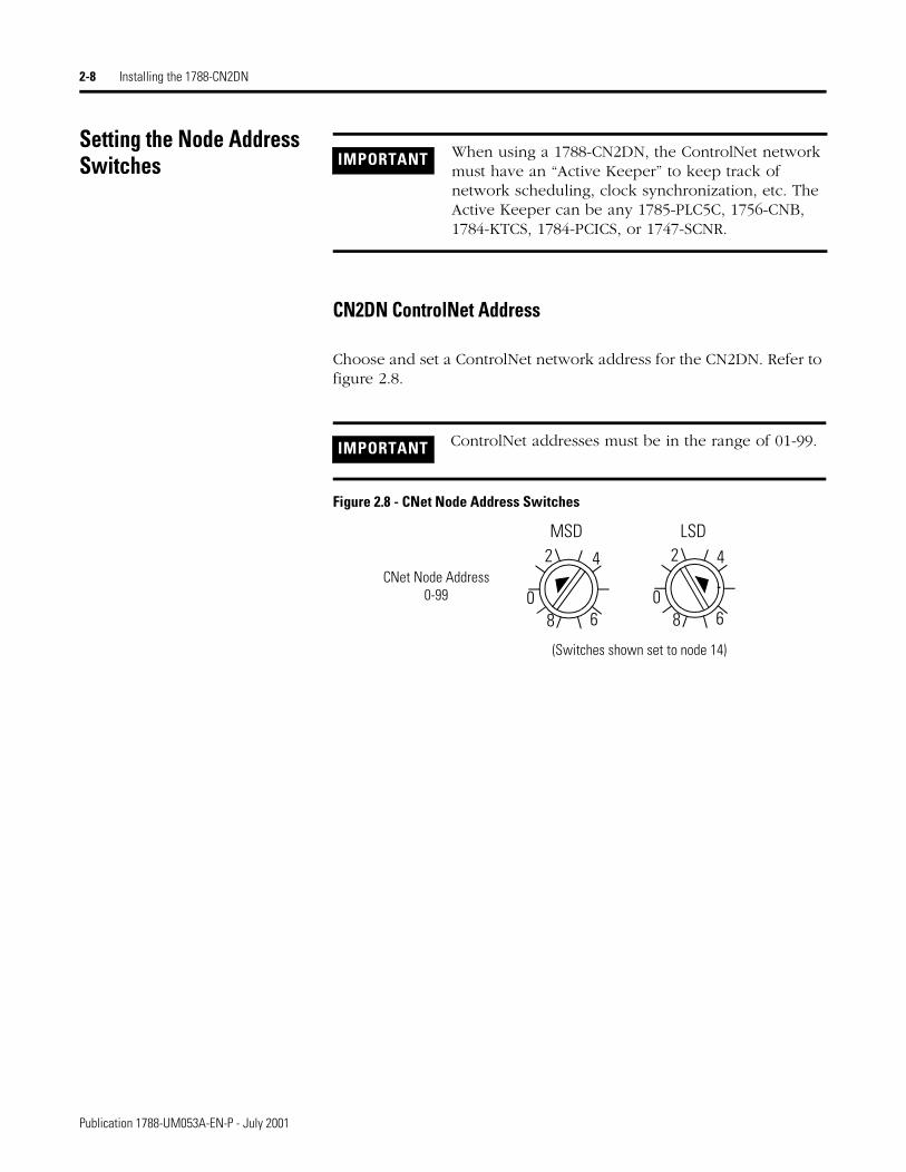
Choose and set a ControlNet network address for the CN2DN. Refer to figure 2.8.
Figure 2.8 - CNet Node Address Switches
IMPORTANT When using a 1788-CN2DN, the ControlNet network must have an “Active Keeper” to keep track of network scheduling, clock synchronization, etc. The Active Keeper can be any 1785-PLC5C, 1756-CNB, 1784-KTCS, 1784-PCICS, or 1747-SCNR.
IMPORTANT ControlNet addresses must be in the range of 01-99.
2 4
680
2 4
680
MSD LSD
CNet Node Address0-99
(Switches shown set to node 14)
Publication 1788-UM053A-EN-P - July 2001

Installing the 1788-CN2DN 2-9
CN2DN DeviceNet Address
Choose and set a DeviceNet network address for the CN2DN. Refer to figure 2.9:
Figure 2.9 - DNet Node Address Switches
Setting the DNet Data Rate Set the data rate for your DeviceNet network: 125K, 250K, or 500K. Data rate settings in the PGM area are not supported. Refer to figure 2.10:
Figure 2.10 - DNet Data Rate Switch
This concludes the hardware installation of the 1788-CN2DN linking device. To use the device you must configure it for your DeviceNet and ControlNet networks. Note that if you are accessing your DeviceNet network from your PC via your ControlNet network, you must perform the ControlNet configuration first. Proceed to one of the following chapters, as applicable:
• ControlNet configuration for a Logix processor - chapter 3
• ControlNet configuration for a PLC-5 processor - chapter 4
• ControlNet configuration for an SLC 500 processor - chapter 5
• DeviceNet configuration - chapter 6
IMPORTANT DeviceNet addresses must be in the range 00-63. The default address is 63. DeviceNet address settings in the PGM area are not supported.
2 4
60
2 4
680
MSD LSD
DNet Node Address0-63
(Switches shown set to node 26)
PGM
(Switch shown set to 125K)PGM
500K
125K
250K
DNet Data Rate
Publication 1788-UM053A-EN-P - July 2001

2-10 Installing the 1788-CN2DN
Mounting DimensionsDimensions in millimeters (mm)
Publication 1788-UM053A-EN-P - July 2001

Chapter 3
ControlLogix ControlNet Configuration
What This Chapter Contains This chapter provides an example of the ControlNet configuration of the 1788-CN2DN linking device for use with a ControlLogix processor. The DeviceNet configuration is independent of the type of processor used and is covered in chapter 6.
The procedure consists of first adding the 1788-CN2DN to the processor’s I/O configuration using RSLogix 5000 software, and then configuring the ControlNet network using RSNetWorx software. A 1756-CNB or 1756-CNBR ControlNet bridge module must be installed in the ControlLogix chassis to connect the controller to the network.
The following table describes where to find specific information.
Topic See pageRSLogix 5000 Configuration 3-2
RSNetWorx for ControlNet Configuration 3-6
Viewing the CN2DN’s Input, Output, and Status Structures 3-9
1 Publication 1788-UM053A-EN-P - July 2001

3-2 ControlLogix ControlNet Configuration
RSLogix 5000 Configuration To interface the 1788-CN2DN module to a ControlLogix processor you must first add a local 1756-CNB module to the I/O configuration, and then add the CN2DN as a “child” of the 1756-CNB. The following example describes this procedure.
1. Open your RSLogix5000 project.
1. Right-click on the I/O Configuration folder at the bottom of the project window, as shown above.
The following pop-up menu will appear.
2. Select New Module.
Publication 1788-UM053A-EN-P - July 2001

ControlLogix ControlNet Configuration 3-3
The Select Module Type window will appear:
3. Select your 1756 ControlNet Bridge from the list and click on OK. The Module Properties window will appear:
4. Enter the following information:
5. Click on the button. The 1756-CNB module will be added to the I/O Configuration folder.
Name Enter a name of your choice.
Description (Optional)
Slot Select the module’s slot number.
Revision Select the firmware minor revision number for the module.
Electronic Keying Select “Compatible Module.”
Publication 1788-UM053A-EN-P - July 2001

3-4 ControlLogix ControlNet Configuration
Next add the 1788-CN2DN linking device to the I/O configuration:
1. Right-click on the 1756-CNB module you have just created. The following pop-up window will appear:
2. Select New Module. The Select Module Type window will appear.
3. Select the 1788-CN2DN ControlNet to DeviceNet Linking Device and click on OK.
Publication 1788-UM053A-EN-P - July 2001

ControlLogix ControlNet Configuration 3-5
The Module Properties window will appear.
4. Enter the following information:
5. When you are done, click on the button.
The I/O configuration should now appear as shown below:
IMPORTANT Click on the Help button if you need assistance in selecting and setting these values.
Name Enter a name of your choice.
Description (Optional)
Comm Format Data
Revision Select the firmware minor revision number for the module.
Node Select the ControlNet node you set with the faceplate switches.
Input Size 124 (default)
Output Size 123 (default)
Status Size 32 (default)
Electronic Keying Compatible Module
Publication 1788-UM053A-EN-P - July 2001
3-6 ControlLogix ControlNet Configuration
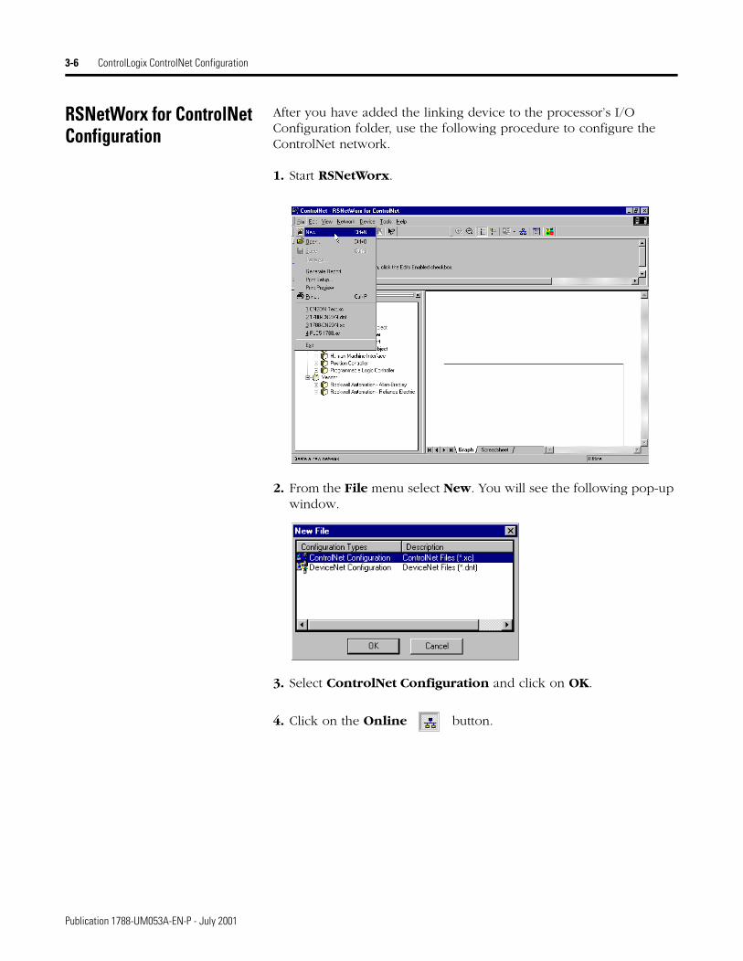
RSNetWorx for ControlNet Configuration
After you have added the linking device to the processor’s I/O Configuration folder, use the following procedure to configure the ControlNet network.
1. Start RSNetWorx.
2. From the File menu select New. You will see the following pop-up window.
3. Select ControlNet Configuration and click on OK.
4. Click on the Online button.
Publication 1788-UM053A-EN-P - July 2001
ControlLogix ControlNet Configuration 3-7
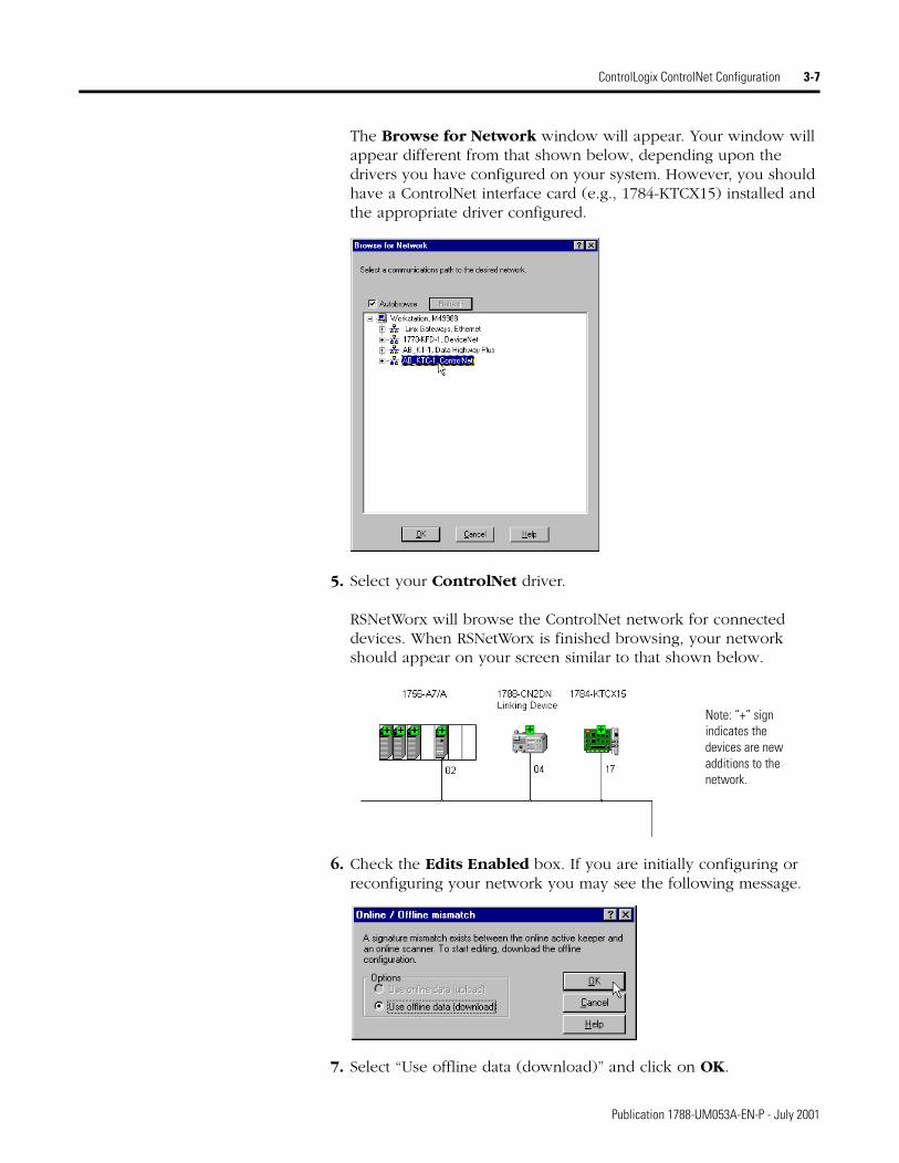
The Browse for Network window will appear. Your window will appear different from that shown below, depending upon the drivers you have configured on your system. However, you should have a ControlNet interface card (e.g., 1784-KTCX15) installed and the appropriate driver configured.
5. Select your ControlNet driver.
RSNetWorx will browse the ControlNet network for connected devices. When RSNetWorx is finished browsing, your network should appear on your screen similar to that shown below.
6. Check the Edits Enabled box. If you are initially configuring or reconfiguring your network you may see the following message.
7. Select “Use offline data (download)” and click on OK.
Note: “+” sign indicates the devices are new additions to the network.
Publication 1788-UM053A-EN-P - July 2001

3-8 ControlLogix ControlNet Configuration
The new devices will be added to the network configuration (Note the “+” signs have disappeared).
8. From the File menu, select Save As. You will see the following message:
9. Select “Optimize and re-write schedule for all connections” and click on OK.
The ControlNet network is now configured and scheduled, and the controller is able to communicate with the ControlNet devices. If you have not done so, you should now configure your DeviceNet network. See chapter 6.
Publication 1788-UM053A-EN-P - July 2001

ControlLogix ControlNet Configuration 3-9
Viewing the CN2DN’s Input, Output, and Status Structures
These examples are based on the configurations described in chapter 6. On the DeviceNet side, the RediStation input is mapped to bits 0-7 of the first input data word and the Photoeye to bits 8-15. The RediStation output is mapped to bits 0-7 of the first output data word. The 1788-CN2DN module also maintains an internal status structure that provides information about the module’s ability to exchange DeviceNet messages with other nodes on the network.
You can view these structures by monitoring the controller tags in RSLogix 5000. The following figure shows the CN2DN’s input structure.
RediStation “Start” bit
Photoeye input bit
1st Input Data Word
CN2DN Status Register“Run” Status bit
Publication 1788-UM053A-EN-P - July 2001
3-10 ControlLogix ControlNet Configuration
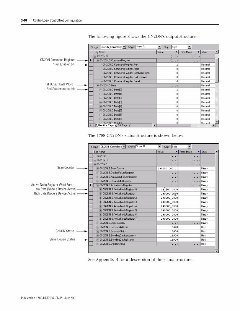
The following figure shows the CN2DN’s output structure.
The 1788-CN2DN’s status structure is shown below.
See Appendix B for a description of the status structure.
RediStation output bit1st Output Data Word
CN2DN Command Register“Run Enable” bit
Scan Counter
Active Node Register Word Zero:Low Byte (Node 7 Device Active)High Byte (Node 9 Device Active)
Slave Device Status
CN2DN Status
Publication 1788-UM053A-EN-P - July 2001

Chapter 4
PLC-5 ControlNet Configuration
What This Chapter Contains This chapter provides an example of the ControlNet configuration of the 1788-CN2DN linking device for a PLC-5/C processor. The procedure consists of configuring the ControlNet network using RSNetWorx software. The DeviceNet configuration is independent of the platform and is covered in chapter 6.
The following table describes where to find specific information.
RSNetWorx for ControlNet Configuration
Use the following procedure to configure your ControlNet network.
1. Run RSNetWorx for ControlNet.
2. Go Online, Browse the network, and check the Edits Enabled box.
Your network will appear on your screen showing the devices on your ControlNet network, similar to the one shown below.
3. Right click on the PLC-5/40C icon on your screen.
Topic See pageRSNetWorx for ControlNet Configuration 4-1
Viewing the CN2DN’s Input, Output, and Status Structures 4-7
1 Publication 1788-UM053A-EN-P - July 2001

4-2 PLC-5 ControlNet Configuration
You will see the following pop-up menu.
4. Select Scanlist Configuration. You will see the screen shown below.
5. Go Online, Enable Edits, and select the 1788-CN2DN.
6. Select the Connection pull-down menu.
7. Select Insert.
Publication 1788-UM053A-EN-P - July 2001
PLC-5 ControlNet Configuration 4-3
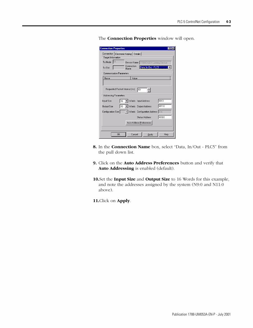
The Connection Properties window will open.
8. In the Connection Name box, select “Data, In/Out - PLC5” from the pull down list.
9. Click on the Auto Address Preferences button and verify that Auto Addressing is enabled (default).
10.Set the Input Size and Output Size to 16 Words for this example, and note the addresses assigned by the system (N9:0 and N11:0 above).
11.Click on Apply.
Publication 1788-UM053A-EN-P - July 2001

4-4 PLC-5 ControlNet Configuration
In order to see the diagnostic tables in the CN2DN you must also create a connection the CN2DN’s status structure.
12. In the Connection Name field, select “Status, In Only - PLC5”.
13.Set the Input Size to 22 words.
14.Note the Input Address. (N9:16 in the example above)
15.Click on OK. (You can leave the other parameters at their default settings.)
Publication 1788-UM053A-EN-P - July 2001
PLC-5 ControlNet Configuration 4-5
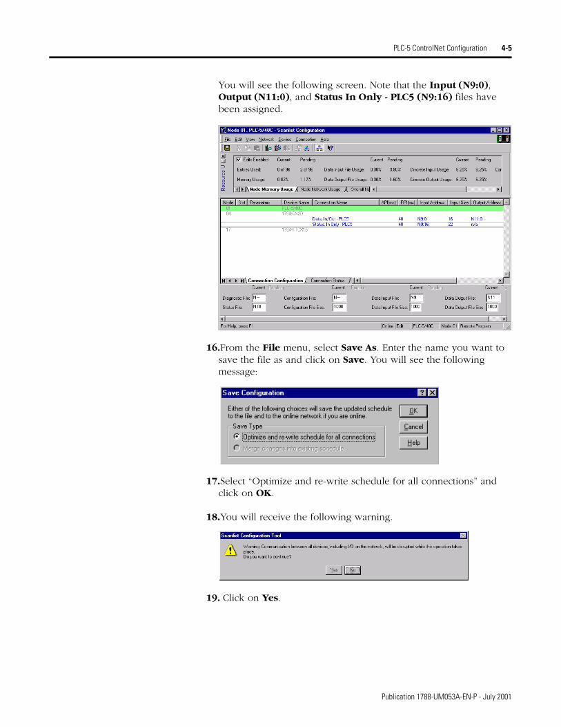
You will see the following screen. Note that the Input (N9:0), Output (N11:0), and Status In Only - PLC5 (N9:16) files have been assigned.
16.From the File menu, select Save As. Enter the name you want to save the file as and click on Save. You will see the following message:
17.Select “Optimize and re-write schedule for all connections” and click on OK.
18.You will receive the following warning.
19. Click on Yes.
Publication 1788-UM053A-EN-P - July 2001
4-6 PLC-5 ControlNet Configuration
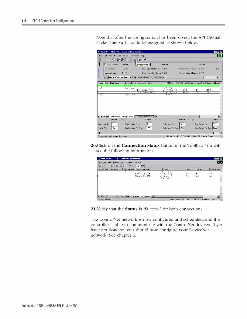
Note that after the configuration has been saved, the API (Actual Packet Interval) should be assigned as shown below.
20.Click on the Connection Status button in the Toolbar. You will see the following information.
21.Verify that the Status is “Success” for both connections.
The ControlNet network is now configured and scheduled, and the controller is able to communicate with the ControlNet devices. If you have not done so, you should now configure your DeviceNet network. See chapter 6.
Publication 1788-UM053A-EN-P - July 2001

PLC-5 ControlNet Configuration 4-7
Viewing the CN2DN’s Input, Output, and Status Structures
This example is based on the configurations described earlier in this chapter and in chapter 6. On the ControlNet side, the CN2DN’s input data was connected to PLC-5 file N9, the output data was connected to file N11, and the status input data was connected as 22 words beginning at word N9:16. In chapter 6, on the DeviceNet side, the RediStation input is mapped to bits 0-7 of the first input word and the Photoeye to bits 8-15. The RediStation output is mapped to bits 0-7 of the first output word.
To view the CN2DN’s input, output, and status structures perform the following steps:
1. Open your project file in RSLogix 5. You will see the files created during the RSNetWorx configuration in the Project window.
2. Select file N9 to view the input word and CN2DN status structure.
Files created during RSNetWorx for ControlNet configuration
Publication 1788-UM053A-EN-P - July 2001

4-8 PLC-5 ControlNet Configuration
The example below shows the mapping of the CN2DN’s input word to file N9.
3. Scroll to N9:16 to see the CN2DN status structure, as seen below.
See Appendix B for a description of the status structure.
CN2DN Status Register
1st Input Data Word “Run” Status bit
Photoeye input bit
RediStation “Start” bit
1788-CN2DN Status Structure:N9:16 to N9:37
Scan Counter
Devices at nodes 7 and 9 are online.
Slave Device Status
CN2DN Status
Publication 1788-UM053A-EN-P - July 2001

PLC-5 ControlNet Configuration 4-9
4. Select file N11 to view the CN2DN’s output word.
This concludes the PLC-5/C example. You should now be able to perform the steps described in this chapter on your actual system.
RediStation output bit
CN2DN Command Register
“Run Enable” bit1st Output Data Word
Publication 1788-UM053A-EN-P - July 2001

4-10 PLC-5 ControlNet Configuration
Publication 1788-UM053A-EN-P - July 2001
Chapter 5
SLC 500 ControlNet Configuration
What This Chapter Contains This chapter provides an example of the ControlNet configuration of 1788-CN2DN linking device for use with a SLC 500 processor. The procedure consists of configuring the ControlNet network using RSNetWorx software. The DeviceNet configuration is independent of the platform and is covered in chapter 6.
The following table describes where to find specific information.
RSNetWorx for ControlNet Configuration
Use the following procedure to configure your ControlNet network.
1. Run RSNetWorx for ControlNet.
2. Go Online, Browse the network, and check the Edits Enabled box.
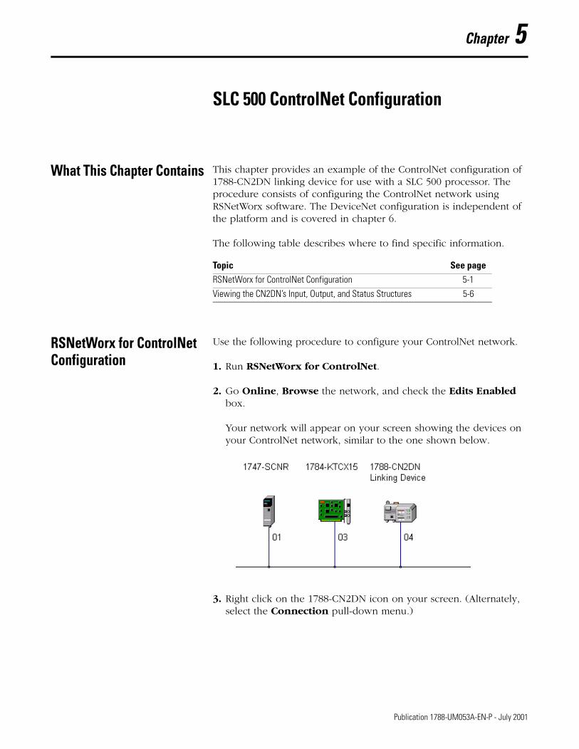
Your network will appear on your screen showing the devices on your ControlNet network, similar to the one shown below.
3. Right click on the 1788-CN2DN icon on your screen. (Alternately, select the Connection pull-down menu.)
Topic See pageRSNetWorx for ControlNet Configuration 5-1
Viewing the CN2DN’s Input, Output, and Status Structures 5-6
1 Publication 1788-UM053A-EN-P - July 2001
5-2 SLC 500 ControlNet Configuration
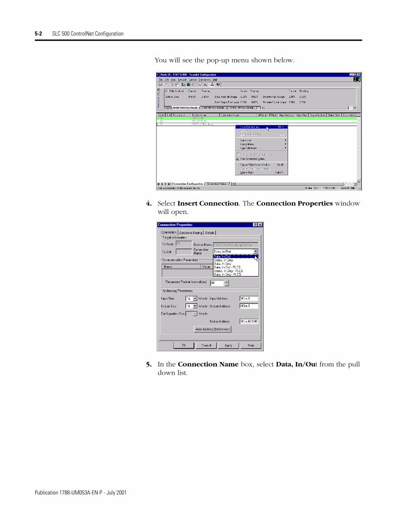
You will see the pop-up menu shown below.
4. Select Insert Connection. The Connection Properties window will open.
5. In the Connection Name box, select Data, In/Out from the pull down list.
Publication 1788-UM053A-EN-P - July 2001

SLC 500 ControlNet Configuration 5-3
Note that in this example we use discrete input and output tables in order to show the mapping to the CN2DN module at the end of this chapter. Normally, you would use the default M1 and M0 files.
6. Click on the Auto Address Preferences button and disable Auto Addressing.
7. Set the Input Size and Output Size to 4 Words.
8. Set the Input Address and Output Address to “I:e.3” and “O:e.3”.
9. Click on Apply.
In order to see the diagnostic tables in the CN2DN you must also create a connection the CN2DN’s status structure.
10.In the Connection Name field, select “Status, In Only”.
Publication 1788-UM053A-EN-P - July 2001
5-4 SLC 500 ControlNet Configuration
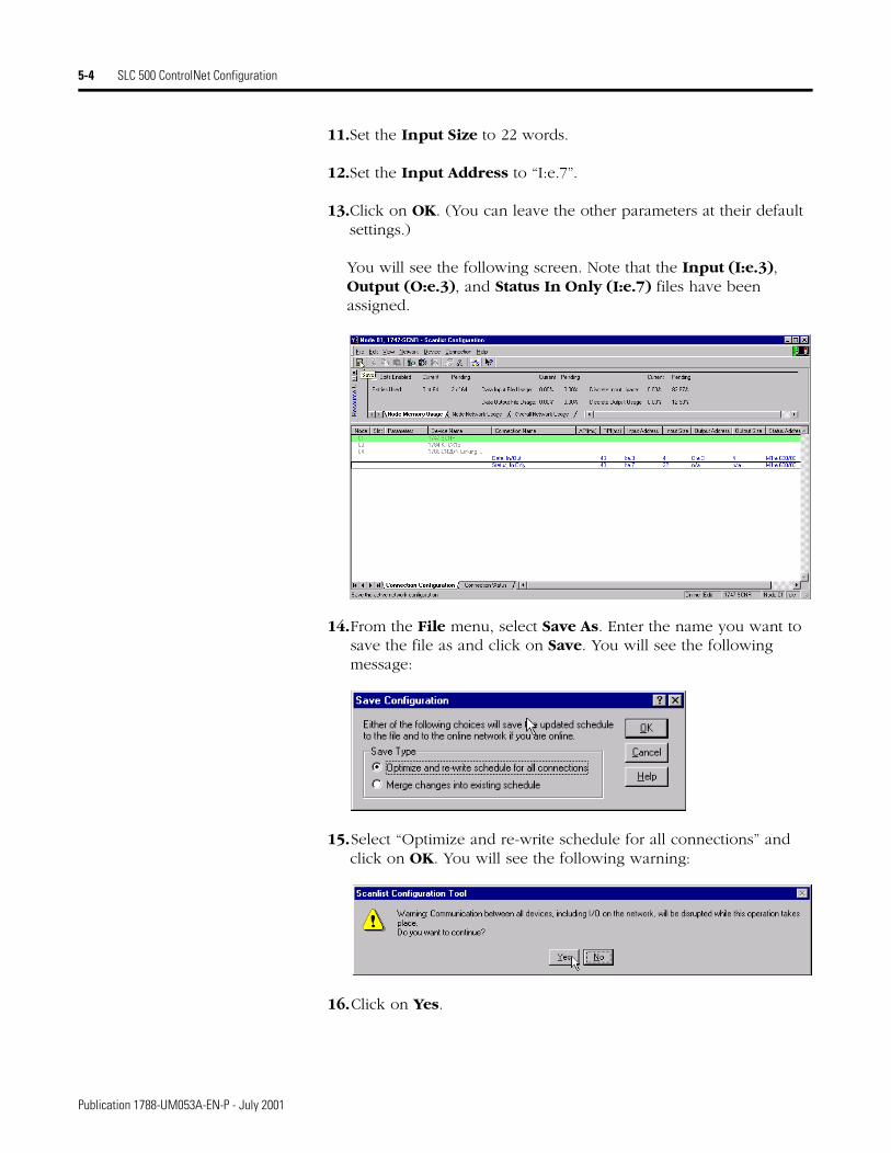
11.Set the Input Size to 22 words.
12.Set the Input Address to “I:e.7”.
13.Click on OK. (You can leave the other parameters at their default settings.)
You will see the following screen. Note that the Input (I:e.3), Output (O:e.3), and Status In Only (I:e.7) files have been assigned.
14.From the File menu, select Save As. Enter the name you want to save the file as and click on Save. You will see the following message:
15.Select “Optimize and re-write schedule for all connections” and click on OK. You will see the following warning:
16.Click on Yes.
Publication 1788-UM053A-EN-P - July 2001

SLC 500 ControlNet Configuration 5-5
Note that after the configuration has been saved, the API (Actual Packet Interval) should be assigned as shown below.
17.Click on the Connection Status button. You will see the following information.
18.Verify that the Status is “Success” for both connections.
The ControlNet network is now configured and scheduled, and the controller is able to communicate with the ControlNet devices. If you have not done so, you should now configure your DeviceNet network. See chapter 6.
Publication 1788-UM053A-EN-P - July 2001
5-6 SLC 500 ControlNet Configuration
Viewing the CN2DN’sInput, Output, and Status Structures
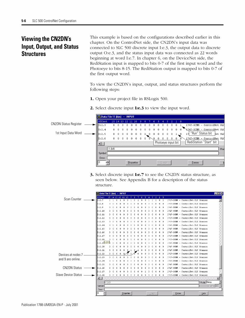
This example is based on the configurations described earlier in this chapter. On the ControlNet side, the CN2DN’s input data was connected to SLC 500 discrete input I:e.3, the output data to discrete output O:e.3, and the status input data was connected as 22 words beginning at word I:e.7. In chapter 6, on the DeviceNet side, the RediStation input is mapped to bits 0-7 of the first input word and the Photoeye to bits 8-15. The RediStation output is mapped to bits 0-7 of the first output word.
To view the CN2DN’s input, output, and status structures perform the following steps:
1. Open your project file in RSLogix 500.
2. Select discrete input I:e.3 to view the input word.
3. Select discrete input I:e.7 to see the CN2DN status structure, as seen below. See Appendix B for a description of the status structure.
Photoeye input bit RediStation “Start” bit
“Run” Status bit
CN2DN Status Register
1st Input Data Word
Scan Counter
Devices at nodes 7 and 9 are online.
Slave Device Status
CN2DN Status
Publication 1788-UM053A-EN-P - July 2001

SLC 500 ControlNet Configuration 5-7
4. Select discrete output O:e.3 to view the CN2DN’s output word.
This concludes the SLC 500 example. You should now be able to perform the steps described in this chapter on your actual system.
RediStation output bit
CN2DN Command Register
1st Output Data Word “Run Enable” bit
Publication 1788-UM053A-EN-P - July 2001

5-8 SLC 500 ControlNet Configuration
Publication 1788-UM053A-EN-P - July 2001

Chapter 6
RSNetWorx for DeviceNet Configuration
What This Chapter Contains This chapter provides an example of configuring a DeviceNet network using RSNetWorx software. The procedure is the same regardless of the platform (ControlLogix, PLC-5, or SLC 500).
Note: Our example accesses the DeviceNet network via the ControlNet network. This requires you to first configure the ControlNet network. This is not necessary if you have direct access to your DeviceNet network (e.g., via a 1770-KFD, 1784-PCD, 1784-PCID, or 1784-PCIDS).
Configuration Procedure Use the following procedure to configure your DeviceNet network:
1. From the RSNetWorx File menu, select New.
You will see the following pop-up window.
1 Publication 1788-UM053A-EN-P - July 2001
6-2 RSNetWorx for DeviceNet Configuration
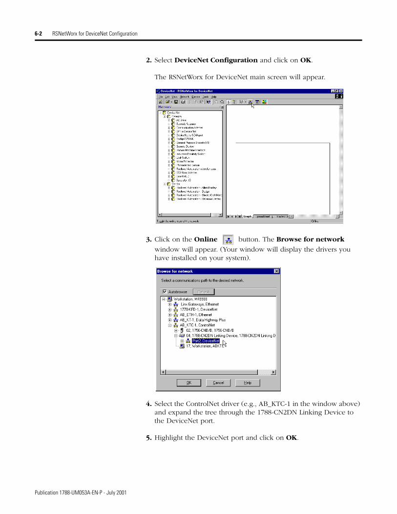
2. Select DeviceNet Configuration and click on OK.
The RSNetWorx for DeviceNet main screen will appear.
3. Click on the Online button. The Browse for network
window will appear. (Your window will display the drivers you have installed on your system).
4. Select the ControlNet driver (e.g., AB_KTC-1 in the window above) and expand the tree through the 1788-CN2DN Linking Device to the DeviceNet port.
5. Highlight the DeviceNet port and click on OK.
Publication 1788-UM053A-EN-P - July 2001

RSNetWorx for DeviceNet Configuration 6-3
The following prompt will appear:
6. Click on OK. RSNetWorx will browse the DeviceNet network. When browsing is complete you should see all of the devices you have on your DeviceNet network. Our example network is shown below.
7. Right-click on the 1788-CN2DN icon. The following pop-up menu will appear:
8. Select Properties.
Publication 1788-UM053A-EN-P - July 2001

6-4 RSNetWorx for DeviceNet Configuration
The following window will appear.
9. Select the Scanlist tab. You will see the following Scanner Configuration Applet.
10.Click on Upload.
Publication 1788-UM053A-EN-P - July 2001
RSNetWorx for DeviceNet Configuration 6-5
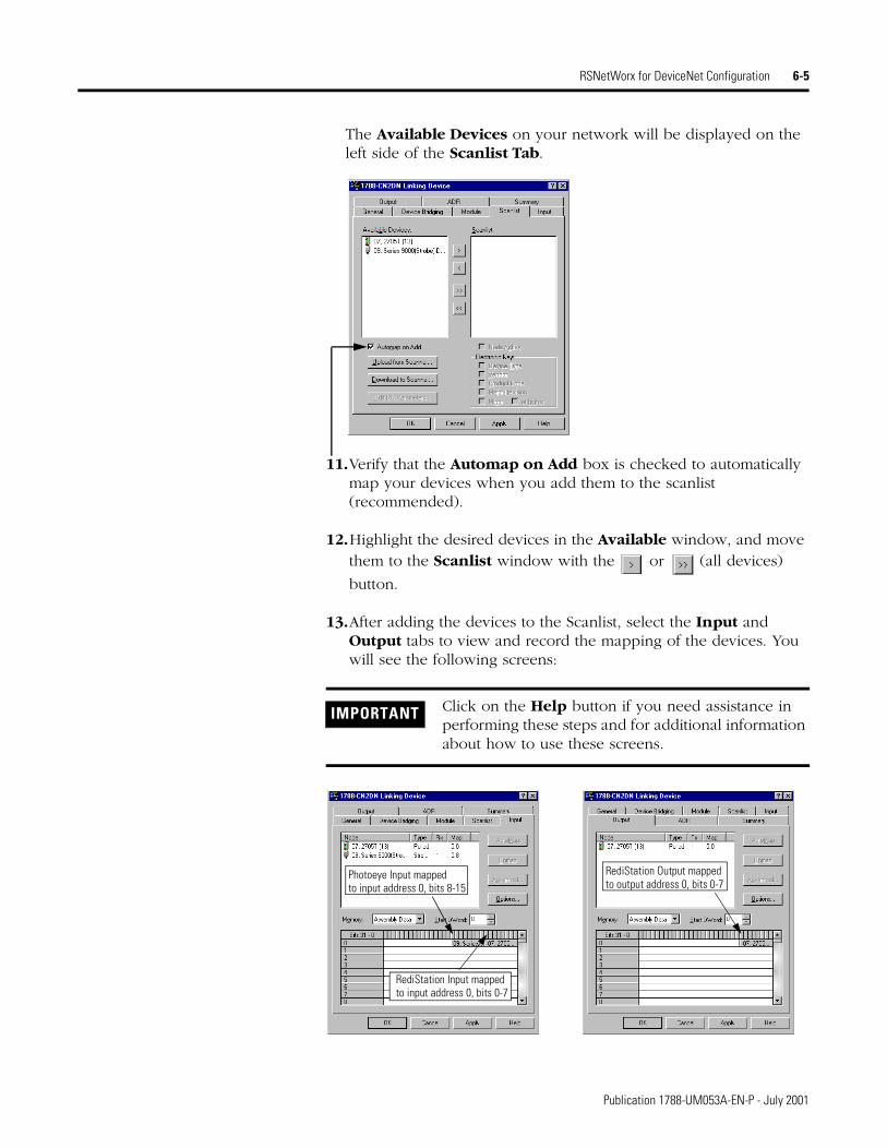
The Available Devices on your network will be displayed on the left side of the Scanlist Tab.
11.Verify that the Automap on Add box is checked to automatically map your devices when you add them to the scanlist (recommended).
12.Highlight the desired devices in the Available window, and move them to the Scanlist window with the or (all devices)
button.
13.After adding the devices to the Scanlist, select the Input and Output tabs to view and record the mapping of the devices. You will see the following screens:
IMPORTANT Click on the Help button if you need assistance in performing these steps and for additional information about how to use these screens.
RediStation Output mappedto output address 0, bits 0-7
Photoeye Input mappedto input address 0, bits 8-15
RediStation Input mappedto input address 0, bits 0-7
Publication 1788-UM053A-EN-P - July 2001
6-6 RSNetWorx for DeviceNet Configuration
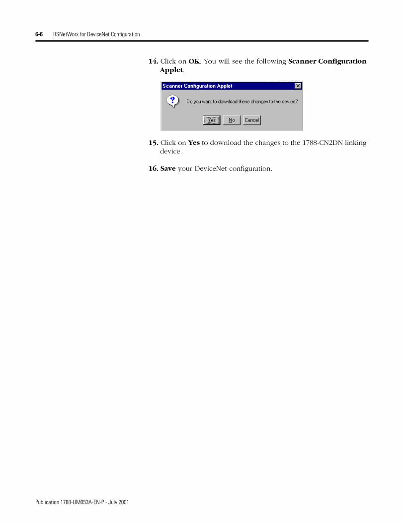
14. Click on OK. You will see the following Scanner Configuration Applet.
15. Click on Yes to download the changes to the 1788-CN2DN linking device.
16. Save your DeviceNet configuration.
Publication 1788-UM053A-EN-P - July 2001
Appendix A
LED Status Indicators
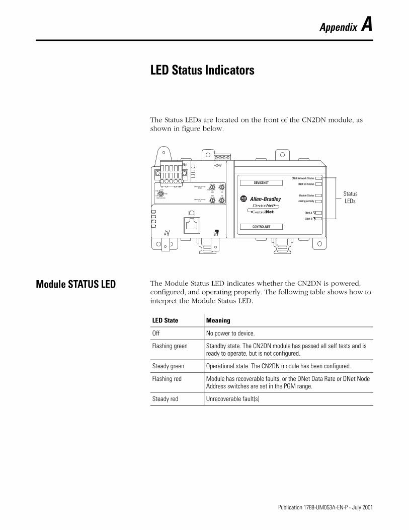
The Status LEDs are located on the front of the CN2DN module, as shown in figure below.
Module STATUS LED The Module Status LED indicates whether the CN2DN is powered, configured, and operating properly. The following table shows how to interpret the Module Status LED.
Status LEDs
LED State Meaning
Off No power to device.
Flashing green Standby state. The CN2DN module has passed all self tests and is ready to operate, but is not configured.
Steady green Operational state. The CN2DN module has been configured.
Flashing red Module has recoverable faults, or the DNet Data Rate or DNet Node Address switches are set in the PGM range.
Steady red Unrecoverable fault(s)
1 Publication 1788-UM053A-EN-P - July 2001
A-2 LED Status Indicators
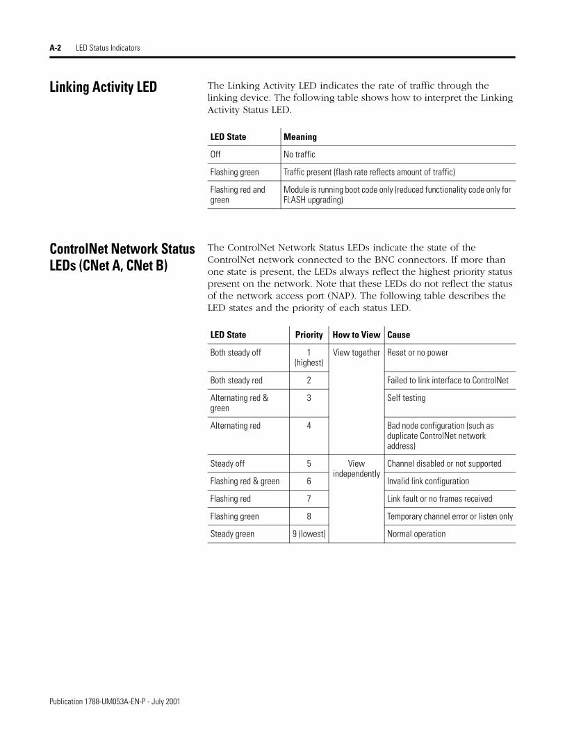
Linking Activity LED The Linking Activity LED indicates the rate of traffic through the linking device. The following table shows how to interpret the Linking Activity Status LED.
ControlNet Network Status LEDs (CNet A, CNet B)
The ControlNet Network Status LEDs indicate the state of the ControlNet network connected to the BNC connectors. If more than one state is present, the LEDs always reflect the highest priority status present on the network. Note that these LEDs do not reflect the status of the network access port (NAP). The following table describes the LED states and the priority of each status LED.
LED State Meaning
Off No traffic
Flashing green Traffic present (flash rate reflects amount of traffic)
Flashing red and green
Module is running boot code only (reduced functionality code only for FLASH upgrading)
LED State Priority How to View Cause
Both steady off 1 (highest)
View together Reset or no power
Both steady red 2 Failed to link interface to ControlNet
Alternating red & green
3 Self testing
Alternating red 4 Bad node configuration (such as duplicate ControlNet network address)
Steady off 5 View independently
Channel disabled or not supported
Flashing red & green 6 Invalid link configuration
Flashing red 7 Link fault or no frames received
Flashing green 8 Temporary channel error or listen only
Steady green 9 (lowest) Normal operation
Publication 1788-UM053A-EN-P - July 2001

LED Status Indicators A-3
DeviceNet Network Status LED (including Slave Mode)
The DeviceNet Network Status LED indicates the functional states of the DNet port. The following table describes each state.
DeviceNet I/O Status LED The DeviceNet I/O Status LED indicates the functional state of the I/O on the DeviceNet. The following describes each state.
LED State Meaning
Off Not online, no network power, or no device power.
Flashing green No connections established, or timed-out.
Steady green At least one connection established, none timed-out.
Flashing red At least one connection in timed-out state.
Steady Red Bus off, or duplicate MAC ID.
LED State Meaning
Off Not online, no network power, or no device power.
Flashing green Processor (controller) in Program (Idle) mode.
Steady green Processor (controller) in Run mode.
Flashing red Not defined.
Steady red Not defined.
Publication 1788-UM053A-EN-P - July 2001

A-4 LED Status Indicators
Publication 1788-UM053A-EN-P - July 2001

Appendix B
1788-CN2DN Input, Output, and Status Structures
The 1788-CN2DN provides a single default input, output, and status structure. These default I/O structures reduce the complexity of connecting DeviceNet I/O and status data with ladder programs. The module creates all 3 structures whether or not DeviceNet nodes are configured or online. RSNetWorx for DeviceNet configures scanlist map segments that are used to copy specific portions of I/O data between the I/O structures and DeviceNet network packets.
Input Structure The control processor receives input data by reading from an input data structure in the 1788-CN2DN module. The scanner (i.e., the CN2DN) receives input data from DeviceNet modules and delivers a copy of these values to the controller. The input structure consists of one 32-bit module status register and an array of 124 32-bit words for input data. The 32-bit module status register reflects the current state of several key module-level operational parameters.
The input structure consists of these data regions.
Input Structure Element Data Typemodule status register 1 x 32-bit register
input_data 124 x 32-bit data array
1 Publication 1788-UM053A-EN-P - July 2001

B-2 1788-CN2DN Input, Output, and Status Structures
Module Status Register Bit Definitions
The bits of the module status register as defined in the following table.
Output Structure The controller sends output by writing output data to the output structure in the 1788-CN2DN module. The CN2DN then delivers a copy of these output values to modules on DeviceNet. The output structure consists of a 32-bit command register and a variable size 32-bit array of up to 123 words for output data.
The output structure consists of these data regions:
Bit Name Description0 Run 1 = in run mode
0 = in idle mode
1 Fault 1 = network is faulted
2 DisableNetwork 1 = network is disabled
3 DeviceFailure 1 = device failure exists (examine the status structure for causes)
4 Autoverify 1 = device I/O size mismatch exists (examine the status structure for details)
5 CommFailure 1 = communication failure exists
6 DupNodeFail 1 = failure due to duplicate node address
7 DnetPowerDetect 1 = DeviceNet power failure
8 - 31 Reserved unused
TIP See page 3-9 (ControlLogix), page 4-8 (PLC-5), or page 5-6 (SLC 500) for the location of this register in the input file.
Output Structure Element
Description Data Type
module command register
This 32-bit register consists of several bits that affect the module’s behavior on the network.
1 x 32-bit register
output_data 123 x 32-bit data array
Publication 1788-UM053A-EN-P - July 2001

1788-CN2DN Input, Output, and Status Structures B-3
Module Command Register Bit Definitions
The bits of the module command register are defined as follows.
Bit Name Description0 Run 1 = run mode
0 = idle mode
1 Fault 1 = fault network
2 DisableNetwork 1 = disable network
3 HaltScanner 1 = halt module
4 Reset 1 = reset module
5 - 31 Reserved unused
IMPORTANT If a module is halted because the HaltScanner bit is set, power must be physically recycled to restart the module.
TIP See page 3-10 (ControlLogix), page 4-9 (PLC-5), or page 5-7 (SLC 500) for the location of this register in the output file.
Publication 1788-UM053A-EN-P - July 2001

B-4 1788-CN2DN Input, Output, and Status Structures
Status Structure The controller receives status information concerning the 1788-CN2DN module’s ability to exchange DeviceNet messages with other nodes by reading from the status structure in the 1788-CN2DN module. The CN2DN periodically updates the contents of the status structure and copies its contents to the controller. The status structure consists of several tables. The bit position of each of the 64 bits that make up a given status table directly corresponds to the node address of a device.
The status structure consists of these data elements:
You can view the status structure by monitoring the controller tags in RSLogix 5000 (chapter 3), or by mapping the status structure to a file in a PLC-5 or SLC 500 processor and viewing the file in RSLogix 5 (chapter 4) or RSLogix 500 (chapter 5).
Status Structure Element
Description Data Type
ScanCounter counter incremented each I/O scan 32-bit
DeviceFailureRegister device failed bit table 64-bit
AutoverifyFailureRegister device I/O size does not match scanner’s internal table
64-bit
DeviceIdleRegister device’s idle bit table 64-bit
ActiveNodeRegister node online bit table 64-bit
ScannerAddress DeviceNet address of CN2DN module 8-bit BCD
ScannerStatus status of CN2DN module 8-bit BCD
ScrollingDeviceAddress scrolls through DeviceNet nodes once per second by address and status(0 = no faults)
8-bit BCD
ScrollingDeviceStatus 8-bit BCD
Reserved Array future expansion (20 bytes) 20 x 8-bit
DeviceStatus DeviceNet node status array, 1 byte per device 64 8-bit
Publication 1788-UM053A-EN-P - July 2001
1788-CN2DN Input, Output, and Status Structures B-5
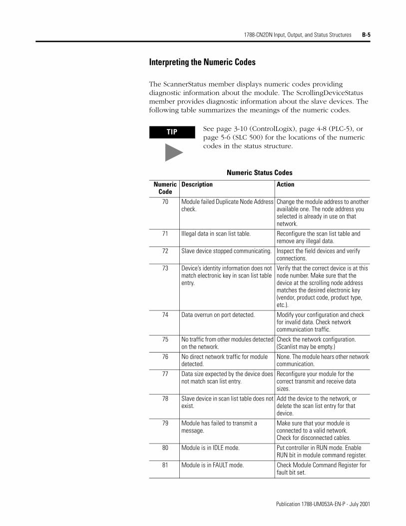
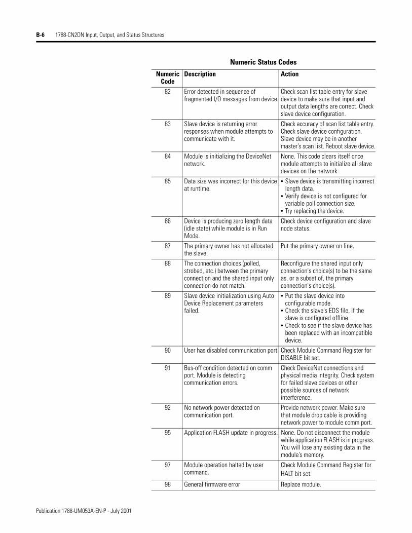
Interpreting the Numeric Codes
The ScannerStatus member displays numeric codes providing diagnostic information about the module. The ScrollingDeviceStatus member provides diagnostic information about the slave devices. The following table summarizes the meanings of the numeric codes.
TIP See page 3-10 (ControlLogix), page 4-8 (PLC-5), or page 5-6 (SLC 500) for the locations of the numeric codes in the status structure.
Numeric Status Codes
Numeric Code
Description Action
70 Module failed Duplicate Node Address check.
Change the module address to another available one. The node address you selected is already in use on that network.
71 Illegal data in scan list table. Reconfigure the scan list table and remove any illegal data.
72 Slave device stopped communicating. Inspect the field devices and verify connections.
73 Device’s identity information does not match electronic key in scan list table entry.
Verify that the correct device is at this node number. Make sure that the device at the scrolling node address matches the desired electronic key (vendor, product code, product type, etc.).
74 Data overrun on port detected. Modify your configuration and check for invalid data. Check network communication traffic.
75 No traffic from other modules detected on the network.
Check the network configuration. (Scanlist may be empty.)
76 No direct network traffic for module detected.
None. The module hears other network communication.
77 Data size expected by the device does not match scan list entry.
Reconfigure your module for the correct transmit and receive data sizes.
78 Slave device in scan list table does not exist.
Add the device to the network, or delete the scan list entry for that device.
79 Module has failed to transmit a message.
Make sure that your module is connected to a valid network.Check for disconnected cables.
80 Module is in IDLE mode. Put controller in RUN mode. Enable RUN bit in module command register.
81 Module is in FAULT mode. Check Module Command Register for fault bit set.
Publication 1788-UM053A-EN-P - July 2001
B-6 1788-CN2DN Input, Output, and Status Structures
82 Error detected in sequence of fragmented I/O messages from device.
Check scan list table entry for slave device to make sure that input and output data lengths are correct. Check slave device configuration.
83 Slave device is returning error responses when module attempts to communicate with it.
Check accuracy of scan list table entry. Check slave device configuration. Slave device may be in another master’s scan list. Reboot slave device.
84 Module is initializing the DeviceNet network.
None. This code clears itself once module attempts to initialize all slave devices on the network.
85 Data size was incorrect for this device at runtime.
• Slave device is transmitting incorrect length data.
• Verify device is not configured for variable poll connection size.
• Try replacing the device.
86 Device is producing zero length data (idle state) while module is in Run Mode.
Check device configuration and slave node status.
87 The primary owner has not allocated the slave.
Put the primary owner on line.
88 The connection choices (polled, strobed, etc.) between the primary connection and the shared input only connection do not match.
Reconfigure the shared input only connection's choice(s) to be the same as, or a subset of, the primary connection's choice(s).
89 Slave device initialization using Auto Device Replacement parameters failed.
• Put the slave device into configurable mode.
• Check the slave's EDS file, if the slave is configured offline.
• Check to see if the slave device has been replaced with an incompatible device.
90 User has disabled communication port. Check Module Command Register for DISABLE bit set.
91 Bus-off condition detected on comm port. Module is detecting communication errors.
Check DeviceNet connections and physical media integrity. Check system for failed slave devices or other possible sources of network interference.
92 No network power detected on communication port.
Provide network power. Make sure that module drop cable is providing network power to module comm port.
95 Application FLASH update in progress. None. Do not disconnect the module while application FLASH is in progress. You will lose any existing data in the module’s memory.
97 Module operation halted by user command.
Check Module Command Register for HALT bit set.
98 General firmware error Replace module.
Numeric Status Codes
Numeric Code
Description Action
Publication 1788-UM053A-EN-P - July 2001

1788-CN2DN Input, Output, and Status Structures B-7
Publication 1788-UM053A-EN-P - July 2001

B-8 1788-CN2DN Input, Output, and Status Structures
Publication 1788-UM053A-EN-P - July 2001

Index
Aabout this user manual P-1 to P-4
BBNC connectors 2-5
Ccommand register bit definitions B-3common techniques used in this manual P-2compatibility information 1-2connecting power 2-3 to 2-4connector pinout 2-7ControlLogix ControlNet configuration 3-1 to 3-10
RSLogix 5000 configuration 3-2 to 3-5RSNetWorx for ControlNet configuration 3-6 to 3-8viewing input, output, and status structures 3-9 to 3-10
ControlNet address 2-8ControlNet configuration
see RSNetWorx for ControlNet configurationControlNet connections 2-5 to 2-6
BNC connectors 2-5network access port (NAP) 2-5
ControlNet network status LEDs A-2
DDeviceNet address 2-9DeviceNet configuration
see RSNetWorx for DeviceNet configurationDeviceNet connections 2-7DeviceNet data rate 2-9DeviceNet I/O status LED A-3DeviceNet network status LED A-3
Eend anchors 2-3examples
about the examples P-2system components P-3
Ffinding more information P-4
Hhardware description 1-2 to 1-3how to use this manual P-1
Iinput structure B-1 to B-2
status register bit definitions B-2input, output, and status structures B-1 to B-5
input structure B-1 to B-2output structure B-2 to B-3status structure B-4 to B-6
installing the 1788-CN2DN 2-1 to 2-10connecting power 2-3 to 2-4ControlNet connections 2-5 to 2-6DeviceNet connections 2-7installation procedure 2-2 to 2-9mounting dimensions 2-10mounting on DIN rail 2-2 to 2-3precautionary statements 2-1setting DeviceNet data rate 2-9setting node address switches 2-8 to 2-9
interpreting the numeric codes B-5 to B-6
LLED status indicators A-1 to A-3
ControlNet network status LEDs A-2DeviceNet I/O status LED A-3DeviceNet network status LED A-3linking activity LED A-2module status LED A-1
linking activity LED A-2
Mmodule description 1-1 to 1-3
product overview 1-1module status LED A-1mounting dimensions 2-10mounting on DIN rail 2-2 to 2-3
Nnetwork access port (NAP) 2-5node address switches 2-8 to 2-9
ControlNet 2-8DeviceNet 2-9
numeric codes B-5 to B-6
Ooutput structure B-2 to B-3
module command register bit definitions B-3
Publication 1788-UM053A-EN-P - July 2001

2 Index
PPLC-5 ControlNet configuration 4-1 to 4-9
RSNetWorx for ControlNet configuration 4-1 to 4-6viewing input, output, and status structures 4-7 to 4-9
product overview 1-1
Rredundant media 2-6related publications P-4removing the CN2DN module 2-3required hardware 1-1required software 1-2RSLogix 5000 configuration 3-2 to 3-5RSNetWorx for ControlNet configuration
with ControlLogix 3-6 to 3-8with PLC-5 4-1 to 4-6with SLC 500 5-1 to 5-5
RSNetWorx for DeviceNet configuration 6-1 to 6-6
Ssetting node address switches 2-8 to 2-9
ControlNet 2-8DeviceNet 2-9
SLC 500 ControlNet configuration 5-1 to 5-7RSNetWorx for ControlNet configuration 5-1 to 5-5viewing input, output, and status structures 5-6 to 5-7
status register bit definitions B-2status structure B-4 to B-6
interpreting the numeric codes B-5 to B-6system requirements 1-1 to 1-2
compatibility information 1-2required hardware 1-1required software 1-2
Vviewing input, output, and status structures
using RSLogix 5 4-7 to 4-9using RSLogix 500 5-6 to 5-7using RSLogix 5000 3-9 to 3-10
Wwho should use this manual P-1
Publication 1788-UM053A-EN-P - July 2001

How Are We Doing?Your comments on our technical publications will help us serve you better in the future.Thank you for taking the time to provide us feedback.
You can complete this form and mail it back to us, visit us online at www.ab.com/manuals, or
email us at [email protected]Please complete the sections below. Where applicable, rank the feature (1=needs improvement, 2=satisfactory, and 3=outstanding).
Pub. Title/Type ControlNet-to-DeviceNet Linking Device User Manual
Cat. No. 1788-CN2DN Pub. No. 1788-UM053A-EN-P Pub. Date July 2001 Part No. 957536-13
Overall Usefulness 1 2 3 How can we make this publication more useful for you?
Completeness(all necessary information
is provided)
1 2 3 Can we add more information to help you?
procedure/step illustration feature
example guideline other
explanation definition
Technical Accuracy(all provided information
is correct)
1 2 3 Can we be more accurate?
text illustration
Clarity(all provided information is
easy to understand)
1 2 3 How can we make things clearer?
Other Comments You can add additional comments on the back of this form.
Your Name Location/Phone
Your Title/Function Would you like us to contact you regarding your comments?
___No, there is no need to contact me
___Yes, please call me
___Yes, please email me at __________________________
___Yes, please contact me via ________________________
Return this form to: Allen-Bradley Marketing Communications, 1 Allen-Bradley Dr., Mayfield Hts., OH 44124-9705
Phone: 440-646-3176 Fax: 440-646-3525 Email: [email protected]
Publication ICCG-5.21- January 2001 PN 955107-82

Other Comments
PLEASE FOLD HERE
NO POSTAGE NECESSARY IF MAILED
IN THE UNITED STATES
BUSINESS REPLY MAILFIRST-CLASS MAIL PERMIT NO. 18235 CLEVELAND OH
POSTAGE WILL BE PAID BY THE ADDRESSEE
1 ALLEN-BRADLEY DRMAYFIELD HEIGHTS OH 44124-9705
PLEASE FASTEN HERE (DO NOT STAPLE)
PLEA
SE R
EMOV
E


Publication 1788-UM053A-EN-P - July 2001 2 PN 957536-13Supersedes publication 1788-5.2B - October 1999 Copyright © 2001 Rockwell Automation. All rights reserved. Printed in USA.
Back Cover