Embed Size (px)
Citation preview

Installation Instructions
ControlNet Fiber Media Planning and Installation GuideCatalog Number 1786 Series

Important User InformationSolid-state equipment has operational characteristics differing from those of electromechanical equipment. Safety Guidelines for the Application, Installation and Maintenance of Solid State Controls (publication SGI-1.1 available from your local Rockwell Automation® sales office or online at http://www.rockwellautomation.com/literature/) describes some important differences between solid-state equipment and hard-wired electromechanical devices. Because of this difference, and also because of the wide variety of uses for solid-state equipment, all persons responsible for applying this equipment must satisfy themselves that each intended application of this equipment is acceptable.
In no event will Rockwell Automation, Inc. be responsible or liable for indirect or consequential damages resulting from the use or application of this equipment.
The examples and diagrams in this manual are included solely for illustrative purposes. Because of the many variables and requirements associated with any particular installation, Rockwell Automation, Inc. cannot assume responsibility or liability for actual use based on the examples and diagrams.
No patent liability is assumed by Rockwell Automation, Inc. with respect to use of information, circuits, equipment, or software described in this manual.
Reproduction of the contents of this manual, in whole or in part, without written permission of Rockwell Automation, Inc., is prohibited.
Throughout this manual, when necessary, we use notes to make you aware of safety considerations.
Allen-Bradley, Rockwell Software, Rockwell Automation, RSNetWorx for ControlNet, and TechConnect are trademarks of Rockwell Automation, Inc.
Trademarks not belonging to Rockwell Automation are property of their respective companies.
WARNING: Identifies information about practices or circumstances that can cause an explosion in a hazardous environment, which may lead to personal injury or death, property damage, or economic loss.
ATTENTION: Identifies information about practices or circumstances that can lead to personal injury or death, property damage, or economic loss. Attentions help you identify a hazard, avoid a hazard, and recognize the consequence
SHOCK HAZARD: Labels may be on or inside the equipment, for example, a drive or motor, to alert people that dangerous voltage may be present.
BURN HAZARD: Labels may be on or inside the equipment, for example, a drive or motor, to alert people that surfaces may reach dangerous temperatures.
IMPORTANT Identifies information that is critical for successful application and understanding of the product.

Summary of Changes
This manual contains new and updated information. Changes throughout this revision are marked by change bars, as shown to the right of this paragraph.
New and Updated Information
This table contains the changes made to this revision.
Topic Page
Updated the terminology for determining fiber topology 15
Added information for allowable ring configurations 18
Included installation procedures for fiber repeater modules anda repeater adapter
59
Updated status indicator descriptions for fiber repeater modules anda repeater adapter
73
Rockwell Automation Publication CNET-IN001C-EN-P - October 2011 3

Summary of Changes
Notes:
4 Rockwell Automation Publication CNET-IN001C-EN-P - October 2011
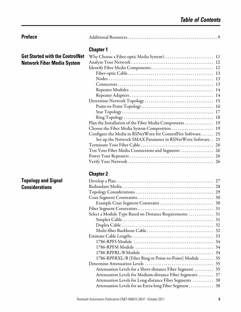
Table of Contents
Preface Additional Resources . . . . . . . . . . . . . . . . . . . . . . . . . . . . . . . . . . . . . . . . . . . . . . . 9
Chapter 1Get Started with the ControlNet Network Fiber Media System
Why Choose a Fiber-optic Media System?. . . . . . . . . . . . . . . . . . . . . . . . . . 11Analyze Your Network . . . . . . . . . . . . . . . . . . . . . . . . . . . . . . . . . . . . . . . . . . . 12Identify Fiber Media Components. . . . . . . . . . . . . . . . . . . . . . . . . . . . . . . . . 12
Fiber-optic Cable . . . . . . . . . . . . . . . . . . . . . . . . . . . . . . . . . . . . . . . . . . . . . 13Nodes . . . . . . . . . . . . . . . . . . . . . . . . . . . . . . . . . . . . . . . . . . . . . . . . . . . . . . . 13Connectors . . . . . . . . . . . . . . . . . . . . . . . . . . . . . . . . . . . . . . . . . . . . . . . . . . 13Repeater Modules . . . . . . . . . . . . . . . . . . . . . . . . . . . . . . . . . . . . . . . . . . . . 14Repeater Adapters . . . . . . . . . . . . . . . . . . . . . . . . . . . . . . . . . . . . . . . . . . . . 14
Determine Network Topology . . . . . . . . . . . . . . . . . . . . . . . . . . . . . . . . . . . . 15Point-to-Point Topology. . . . . . . . . . . . . . . . . . . . . . . . . . . . . . . . . . . . . . 16Star Topology . . . . . . . . . . . . . . . . . . . . . . . . . . . . . . . . . . . . . . . . . . . . . . . . 17Ring Topology . . . . . . . . . . . . . . . . . . . . . . . . . . . . . . . . . . . . . . . . . . . . . . . 18
Plan the Installation of the Fiber Media Components . . . . . . . . . . . . . . . 19Choose the Fiber Media System Composition . . . . . . . . . . . . . . . . . . . . . . 19Configure the Media in RSNetWorx for ControlNet Software. . . . . . . 25
Set up the Network SMAX Parameter in RSNetWorx Software . . 25Terminate Your Fiber Cable . . . . . . . . . . . . . . . . . . . . . . . . . . . . . . . . . . . . . . 26Test Your Fiber Media Connections and Segments . . . . . . . . . . . . . . . . . 26Power Your Repeaters . . . . . . . . . . . . . . . . . . . . . . . . . . . . . . . . . . . . . . . . . . . . 26Verify Your Network . . . . . . . . . . . . . . . . . . . . . . . . . . . . . . . . . . . . . . . . . . . . . 26
Chapter 2Topology and Signal Considerations
Develop a Plan . . . . . . . . . . . . . . . . . . . . . . . . . . . . . . . . . . . . . . . . . . . . . . . . . . . 27Redundant Media . . . . . . . . . . . . . . . . . . . . . . . . . . . . . . . . . . . . . . . . . . . . . . . . 28Topology Considerations . . . . . . . . . . . . . . . . . . . . . . . . . . . . . . . . . . . . . . . . . 29Coax Segment Constraints . . . . . . . . . . . . . . . . . . . . . . . . . . . . . . . . . . . . . . . . 30
Example Coax Segment Constraint . . . . . . . . . . . . . . . . . . . . . . . . . . . . 30Fiber Segment Constraints . . . . . . . . . . . . . . . . . . . . . . . . . . . . . . . . . . . . . . . . 31Select a Module Type Based on Distance Requirements . . . . . . . . . . . . . 31
Simplex Cable . . . . . . . . . . . . . . . . . . . . . . . . . . . . . . . . . . . . . . . . . . . . . . . . 31Duplex Cable . . . . . . . . . . . . . . . . . . . . . . . . . . . . . . . . . . . . . . . . . . . . . . . . 32Multi-fiber Backbone Cable . . . . . . . . . . . . . . . . . . . . . . . . . . . . . . . . . . . 32
Estimate Cable Lengths. . . . . . . . . . . . . . . . . . . . . . . . . . . . . . . . . . . . . . . . . . . 331786-RPFS Module . . . . . . . . . . . . . . . . . . . . . . . . . . . . . . . . . . . . . . . . . . 341786-RPFM Module . . . . . . . . . . . . . . . . . . . . . . . . . . . . . . . . . . . . . . . . . 341786-RPFRL/B Module . . . . . . . . . . . . . . . . . . . . . . . . . . . . . . . . . . . . . . 341786-RPFRXL/B (Fiber Ring or Point-to-Point) Module . . . . . . . 35
Determine Attenuation Levels . . . . . . . . . . . . . . . . . . . . . . . . . . . . . . . . . . . . 35Attenuation Levels for a Short-distance Fiber Segment . . . . . . . . . . 35Attenuation Levels for Medium-distance Fiber Segments . . . . . . . . 37Attenuation Levels for Long-distance Fiber Segments . . . . . . . . . . . 38Attenuation Levels for an Extra-long Fiber Segment . . . . . . . . . . . . . 38
Rockwell Automation Publication CNET-IN001C-EN-P - October 2011 5

Table of Contents
Determine Propagation Delay . . . . . . . . . . . . . . . . . . . . . . . . . . . . . . . . . . . . . 38Maximum Propagation Delay Through a Network . . . . . . . . . . . . . . 39Maximum Propagation Delay and Skew Through a Redundant Network. . . . . . . . . . . . . . . . . . . . . . . . . . . . . . . . 40
Chapter 3Guidelines for Fiber-optic Installation
General Rules and Safety . . . . . . . . . . . . . . . . . . . . . . . . . . . . . . . . . . . . . . . . . . 43Warnings . . . . . . . . . . . . . . . . . . . . . . . . . . . . . . . . . . . . . . . . . . . . . . . . . . . . . . . . 43
Hire Fiber-optic Specialists for Installation and Certification . . . . . 43Guidelines for Handling Fiber-optic Cable. . . . . . . . . . . . . . . . . . . . . . 44
Types of Fiber Media Installations . . . . . . . . . . . . . . . . . . . . . . . . . . . . . . . . . 45Pulled Application Guidelines . . . . . . . . . . . . . . . . . . . . . . . . . . . . . . . . . 45Direct Attachment. . . . . . . . . . . . . . . . . . . . . . . . . . . . . . . . . . . . . . . . . . . . 45Indirect Attachment . . . . . . . . . . . . . . . . . . . . . . . . . . . . . . . . . . . . . . . . . . 46Conduit and Duct Installation . . . . . . . . . . . . . . . . . . . . . . . . . . . . . . . . . 46Aerial Installation. . . . . . . . . . . . . . . . . . . . . . . . . . . . . . . . . . . . . . . . . . . . . 48Direct Burial Installation . . . . . . . . . . . . . . . . . . . . . . . . . . . . . . . . . . . . . . 50Open Trench Installation . . . . . . . . . . . . . . . . . . . . . . . . . . . . . . . . . . . . . 50Vertical Installation . . . . . . . . . . . . . . . . . . . . . . . . . . . . . . . . . . . . . . . . . . . 52
Chapter 4Terminate Your Fiber-optic Cable
What Is Termination? . . . . . . . . . . . . . . . . . . . . . . . . . . . . . . . . . . . . . . . . . . . . 53Terminate Your Cable . . . . . . . . . . . . . . . . . . . . . . . . . . . . . . . . . . . . . . . . . . . . 54
Chapter 5Verify Your Network Set Network Parameters . . . . . . . . . . . . . . . . . . . . . . . . . . . . . . . . . . . . . . . . . . 55
Measure Power Loss . . . . . . . . . . . . . . . . . . . . . . . . . . . . . . . . . . . . . . . . . . . . . . 55OTDR Measurement . . . . . . . . . . . . . . . . . . . . . . . . . . . . . . . . . . . . . . . . . . . . . 57
Appendix AInstall Your Fiber Repeater Modules and Repeater Adapters
Installation Guidelines . . . . . . . . . . . . . . . . . . . . . . . . . . . . . . . . . . . . . . . . . . . . 59Mount the Fiber Module. . . . . . . . . . . . . . . . . . . . . . . . . . . . . . . . . . . . . . . . . . 60
Install the Ferrites. . . . . . . . . . . . . . . . . . . . . . . . . . . . . . . . . . . . . . . . . . . . . 62Connect a 1786-RPFS Module . . . . . . . . . . . . . . . . . . . . . . . . . . . . . . . . . . . . 65Connect Fiber Repeater Modules . . . . . . . . . . . . . . . . . . . . . . . . . . . . . . . . . . 66
Terminate the Cable . . . . . . . . . . . . . . . . . . . . . . . . . . . . . . . . . . . . . . . . . . 67Wire a Repeater Adapter Module . . . . . . . . . . . . . . . . . . . . . . . . . . . . . . . . . . 68Troubleshoot the Module . . . . . . . . . . . . . . . . . . . . . . . . . . . . . . . . . . . . . . . . . 69Specifications forFiber-optic Cable . . . . . . . . . . . . . . . . . . . . . . . . . . . . . . . . . . . . . . . . . . . . . . . . . 70
1786-RPFS Fiber-optic Cable. . . . . . . . . . . . . . . . . . . . . . . . . . . . . . . . . . 701786-RPFM Fiber-optic Cable. . . . . . . . . . . . . . . . . . . . . . . . . . . . . . . . . 701786-RPFRL/B Fiber-optic Cable . . . . . . . . . . . . . . . . . . . . . . . . . . . . . 701786-RPFRXL/B Fiber-optic Cable . . . . . . . . . . . . . . . . . . . . . . . . . . . . 71
6 Rockwell Automation Publication CNET-IN001C-EN-P - October 2011

Table of Contents
Appendix BStatus Indicators 1786-RPFS and 1786-RPFM Status Indicators. . . . . . . . . . . . . . . . . . 76
1786-RPFRL/B or 1786-RPFRXL/B Status Indicators . . . . . . . . . . 771786-RPFRL/B or 1786-RPFRXL/B Relay Contact Connectors. 78
Glossary . . . . . . . . . . . . . . . . . . . . . . . . . . . . . . . . . . . . . . . . . . . . . . . . . . . . . . . . . . . . . . . . . 79
Index . . . . . . . . . . . . . . . . . . . . . . . . . . . . . . . . . . . . . . . . . . . . . . . . . . . . . . . . . . . . . . . . . 83
Rockwell Automation Publication CNET-IN001C-EN-P - October 2011 7

Table of Contents
Notes:
8 Rockwell Automation Publication CNET-IN001C-EN-P - October 2011

Preface
This guide provides basic information for fiber cable planning and installation. Actual procedures for installing your system may vary depending on cable style and installation environment. We recommend that you consult a network design specialist for the design of your fiber network.
Refer to the Glossary for clarification of terms associated with fiber technologies.
Additional Resources These documents contain additional information concerning related products from Rockwell Automation.
You can view or download publications at http://www.rockwellautomation.com/literature/. To order paper copies of technical documentation, contact your local Allen-Bradley distributor or Rockwell Automation sales representative.
IMPORTANT To successfully apply the concepts and techniques contained in this manual, you must have a fundamental knowledge of electronics and electrical codes.
Resource Description
NetLinx Selection Guide, publication NETS-SG001. Describes the NetLinx-based networks—DeviceNet, ControlNet, and EtherNet/IP.
ControlNet Media System Components List, publication AG-PA002
Lists category numbers and specifications for the components that comprise the ControlNet media system.
ControlLogix System User Manual,publication 1756-UM001
Describes how to use your ControlLogix operating system.
ControlNet Modular Repeater Adapter Installation Instructions, publication 1786-IN013
Provides instructions for installing arepeater adapter.
ControlNet Modules in Logix5000 Control Systems User Manual, publication CNET-UM001
Describes how your Logix5000 controller communicates with different devices on the ControlNet network.
ControlNet IP67 Tap and Cable AssemblyKit Installation Instructions,publication 1786-IN017
Provides installation instructions for a tap with an IP67 rating.
ControlNet Coax Media Planning and Installation Guide, publication CNET-IN002
Describes the media that comprises a copper cable system.
Industrial Automation Wiring and Grounding Guidelines, publication 1770-4.1
Provides general guidelines for installing a Rockwell Automation industrial system.
Product Certifications website, http://www.ab.com Provides declarations of conformity, certificates, and other certification details.
Rockwell Automation Publication CNET-IN001C-EN-P - October 2011 9

10 Rockwell Automation Publication CNET-IN001C-EN-P - October 2011
Preface
Notes:
Chapter 1
Get Started with the ControlNet Network Fiber Media System
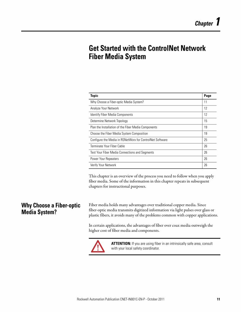
This chapter is an overview of the process you need to follow when you apply fiber media. Some of the information in this chapter repeats in subsequent chapters for instructional purposes.
Why Choose a Fiber-optic Media System?
Fiber media holds many advantages over traditional copper media. Since fiber-optic media transmits digitized information via light pulses over glass or plastic fibers, it avoids many of the problems common with copper applications.
In certain applications, the advantages of fiber over coax media outweigh the higher cost of fiber media and components.
Topic Page
Why Choose a Fiber-optic Media System? 11
Analyze Your Network 12
Identify Fiber Media Components 12
Determine Network Topology 15
Plan the Installation of the Fiber Media Components 19
Choose the Fiber Media System Composition 19
Configure the Media in RSNetWorx for ControlNet Software 25
Terminate Your Fiber Cable 26
Test Your Fiber Media Connections and Segments 26
Power Your Repeaters 26
Verify Your Network 26
ATTENTION: If you are using fiber in an intrinsically safe area, consult with your local safety coordinator.
Rockwell Automation Publication CNET-IN001C-EN-P - October 2011 11

Chapter 1 Get Started with the ControlNet Network Fiber Media System
.
Analyze Your Network Take the time to analyze your current or new network application to see where it makes the most sense to use coax or fiber media. If you are creating a new network or adding fiber to an existing network, create a design plan for the fiber segments of your network and identify the purpose for the fiber segments.
By creating a plan and analyzing your design you will be eliminating the potential for misapplication of media. Use the example topologies to determine your network’s topology. When you understand your network’s topology it will help you determine the media components you need to achieve yourapplication requirements.
Identify Fiber Media Components
The ControlNet network fiber media system is comprised of these components:• Fiber-optic Cable• Nodes• Connectors• Repeater Modules• Repeater Adapters
For information on purchasing these components, see the ControlNet Media System Components List, publication AG-PA002.
Table 1 - Fiber Media Advantages
Features Benefits
Electrical isolation Fiber media is isolated from any potential electrical sources that cause disruptions on copper media. Fiber media iswell-suited for installations between buildings, and provides immunity to lightning strikes.
Immunity to interference Fiber media is immune to EMI (electromagnetic interference) since it uses light pulses on glass fibers. Fiber media is effective in noisy environments (heavy machinery, multiple cable systems, and so forth) where copper could suffer disruptions. Fiber media is also suited forhigh-voltage environments.
Longer distances Fiber media has less transmission loss than copper media. The lower loss in fiber media means fewer repeaters than copper media, making fiber more effective for applications requiring long-distance media connections.
Decreased size and weight Fiber media is smaller and lighter than coax media for ease of installation.
Entry into hazardous areas Fiber media is a portal for information into hazardous areas, reducing the risk of injury. For more information on choosing components for use in hazardous areas, refer to the ControlNet EX Media Planning and Installation Guide, publication CNET-IN003.
12 Rockwell Automation Publication CNET-IN001C-EN-P - October 2011

Get Started with the ControlNet Network Fiber Media System Chapter 1
Fiber-optic Cable
Fiber-optic cables consist of three major components, the buffer and coating, cladding, and the core.
Figure 1 - Fiber-optic Cable Components
Nodes
A network is a collection of segments with nodes connected together by repeaters. A node is any physical device connecting to the ControlNet fiber or ControlNet media system that requires a network address to function onthe network.
Connectors
Fiber cable connectors connect fiber cable to the fiber repeater module. The medium, long, and extra-long distance fiber repeater modules use an ST-type connector and the short-distance fiber repeater modules use a V-pin type connector. The short-distance fiber cables come factory terminated invarious lengths. You can increase the distance of the network by using low loss cable and connectors.
See page 33 for more information.
Core
Coating
Cladding
Buffer
Table 2 - Fiber-optic Cable Description
Parts Description
Buffer and coating The buffer and coating are the material that surround the glass fiber. They are responsible for protecting the fiber strands fromphysical damage.
Cladding The cladding is a material that provides internal reflection so that the light pulses can travel the length of the fiber without escaping from the fiber.
Core The core is the cylinder consisting of glass fiber that carries information in the form of light pulses.
Rockwell Automation Publication CNET-IN001C-EN-P - October 2011 13

Chapter 1 Get Started with the ControlNet Network Fiber Media System
Repeater Modules
There are two types of repeater modules: coax repeater (catalog number1786-RPCD) and fiber repeaters (catalog numbers 1786-RPFS, 1786-RPFM, 1786-RPFRL/B, and 1786-RPFRXL/B). Although you can repeat coax signals on a network by using a 1786-RPCD module, this manual mainly focuses on fiber cabling for the fiber repeater modules.
See the ControlNet Coax Media Planning and Installation Guide, publication CNET-IN002, for more information on ControlNet copper networks.
The fiber repeater modules send an optical signal through the fiber cable to the next fiber repeater module on the network. The combination of the repeater adapter (see below) and a fiber repeater module, such as the 1786-RPFM, is referred to as a fiber repeater.
Repeater Adapters
The ControlNet network uses a modular fiber repeater system. The 1786-RPA/B repeater adapter connects to both coax and fiber media, supplies power to the repeater modules, and repeats signals from the coax media to the fiber repeater modules.
The repeater adapter can supply a maximum of 1.6 A @5V DC of current to power the repeater modules.
To determine how many repeater modules you can use with a single repeater adapter, calculate the current draw of all repeater modules in your system. Do not exceed 1.6 A @ 5V DC per repeater adapter.
Table 3 - Repeater Module Current Draw
Repeater Module Backplane Current Draw
1786-RPFS 300 mA
1786-RPFM 400 mA
1786-RPFRL/B 570 mA
1786-RPFRXL/B 570 mA
1786-RPCD 400 mA
IMPORTANT The 1786-RPFRL/B and 1786-RPFRXL/B repeater modules require 570 mA each, therefore you can attach only two of these modules to a1786-RPA/B repeater adapter.
Regardless of repeater module current draw, you are limited to a maximum of four repeater modules per repeater adapter.
14 Rockwell Automation Publication CNET-IN001C-EN-P - October 2011
Get Started with the ControlNet Network Fiber Media System Chapter 1
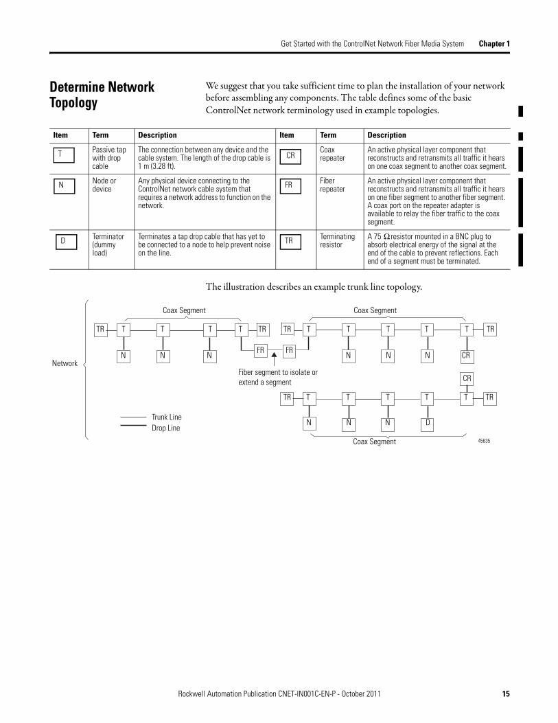
Determine Network Topology
We suggest that you take sufficient time to plan the installation of your network before assembling any components. The table defines some of the basic ControlNet network terminology used in example topologies.
The illustration describes an example trunk line topology.
Item Term Description Item Term Description
Passive tap with drop cable
The connection between any device and the cable system. The length of the drop cable is 1 m (3.28 ft).
Coax repeater
An active physical layer component that reconstructs and retransmits all traffic it hears on one coax segment to another coax segment.
Node or device
Any physical device connecting to the ControlNet network cable system that requires a network address to function on the network.
Fiber repeater
An active physical layer component that reconstructs and retransmits all traffic it hears on one fiber segment to another fiber segment. A coax port on the repeater adapter is available to relay the fiber traffic to the coax segment.
Terminator (dummy load)
Terminates a tap drop cable that has yet to be connected to a node to help prevent noise on the line.
Terminating resistor
A 75 Ω resistor mounted in a BNC plug to absorb electrical energy of the signal at the end of the cable to prevent reflections. Each end of a segment must be terminated.
T CR
N FR
D TR
41326
Network
Coax Segment Coax Segment
Coax Segment
TT TT T T T T T
T T T T T
N NN N NN
N N DN
FR FR
CR
CR
TR TR TR
TR TR
TR
Trunk LineDrop Line
Fiber segment to isolate or extend a segment
45635
Rockwell Automation Publication CNET-IN001C-EN-P - October 2011 15

Chapter 1 Get Started with the ControlNet Network Fiber Media System
You can configure these topologies on a ControlNet network:• Point-to-Point Topology• Star Topology• Ring Topology
Point-to-Point Topology
Point-to-point is also called a bus or a trunk line topology. A point-to-point topology can be described as one fiber module transmitting to another module. For example, you cannot transmit from a medium-distance module to ashort-distance module.
Figure 2 - Example Point-to-Point (Trunk Line) Topology
Coax Segment 1 Coax Segment 2 Coax Segment 3
Fiber Cable 1 Fiber Cable 2 Fiber Cable 3
See Important below
IMPORTANT It is not necessary to install nodes on coax segments. If you are using only the repeaters to extend the network, install a 75-Ω terminator (catalog number 1786-XT) on the BNC coax connector on the1786-RPA/B repeater adapter or 1786-RPCD module. This should be done to all repeater modules that are not connected to coax segments.
16 Rockwell Automation Publication CNET-IN001C-EN-P - October 2011

Get Started with the ControlNet Network Fiber Media System Chapter 1
Star Topology
In a star topology, all segments of the fiber network start from a central location.
Figure 3 - Star Topology
31238-M
*
* See Important on page 16
*
Rockwell Automation Publication CNET-IN001C-EN-P - October 2011 17

Chapter 1 Get Started with the ControlNet Network Fiber Media System
Ring Topology
A ring topology provides redundancy by providing two data paths in a single ring. A ring can sustain two faults before that data connection is lost. You should consider a ring when your devices (Controller and I/O) are single port (A only) and media redundancy is required. Only the 1786-RPFRL and 1786-RPFRXL repeater modules support ring topologies.
In a ring topology on the ControlNet network, you can use:• Up to 5 repeaters by using one 1786-RPA/A repeater adapter.• The 1786-RPA/B repeater adapter allows for a maximum of 20
1786-RPFRL (long distance) or 1786-RPFRL/X (extra long-distance) ring repeaters.
Figure 4 - Ring Topology
If a ring is broken, the configuration then becomes a linear bus and the number of repeaters in SERIES depends on where the ring is broken. You will have as many repeaters as in the original ring.
See page 29 to determine different topology constraints.
Up to 20 1786-RPFR(X)Lrepeaters on a fiber ring.
Fiber
Fiber
Fiber Fiber
Fiber
Fiber
Fiber
Node(s)
Node(s)
Node(s) Node(s)
Node(s)
Node(s)
Node(s)
RPA + RPFRXL
RPA + RPFRXL
RPA + RPFRXL
RPA + RPFRXL
RPA + RPFRXL
RPA + RPFRXL
RPA + RPFRXL
Coax
Coax
Coax
Coax
Coax
Coax
Coax
Coax Network
Coax Network
18 Rockwell Automation Publication CNET-IN001C-EN-P - October 2011

Get Started with the ControlNet Network Fiber Media System Chapter 1
Plan the Installation of the Fiber Media Components
During the planning phase of your network design, create checklists to help you determine the following components that are needed in an application:
• Number of nodes in your network
• Length of the fiber segments
• Number of fiber connectors and splices in your network
• Calculate the maximum allowable segment length
• Any additional repeaters and coax segments you need
Choose the Fiber Media System Composition
The fiber repeater consists of the following:
• A 1786-RPA repeater adapter
• Up to two 1786-RPFRL/B (long-distance) or 1786-RPFRXL/B (extra-long distance) fiber repeater modules
• Up to four 1786-RPFS (short-distance) or 1786-RPFM (medium-distance) fiber repeater modules
It is allowable to mix these repeater modules on a single repeater adapter.
Refer to Table 3 on page 14 to determine how many repeater modules you can connect to one repeater adapter. The number of repeaters and the total cable length depends on your network topology limits and the repeater modules you select.
TIP In a network containing a fiber repeater module, such as a1786-RPFRL/B or 1786-RPFRXL/B module, you cannot have more than 98 node addresses assigned.
Rockwell Automation Publication CNET-IN001C-EN-P - October 2011 19

Chapter 1 Get Started with the ControlNet Network Fiber Media System
You can use fiber repeaters for these tasks:• Extend the total length of your segment (point-to-point or
trunk line topology)• Create star and ring configurations (multiple directions from one point)• Cross into hazardous areas
When you configure your network by using fiber repeaters, you can install them in one of the following ways:
ATTENTION: In hazardous areas, you must use products specifically designed for that purpose. You can use fiber repeaters that are designed for hazardous areas as a link from yournon-hazardous area to your hazardous area.
For hazardous locations, consult the ControlNet EX Media Planning and Installation Manual, publication CNET-IN003.
Fiber Repeater Installation Page
Series 21
Parallel 22
Combination of series and parallel 23
Ring (only fiber) 24
ATTENTION: The maximum distance in the network is limited by the distance between the two nodes farthest from one another, and the number of repeaters.
20 Rockwell Automation Publication CNET-IN001C-EN-P - October 2011

Get Started with the ControlNet Network Fiber Media System Chapter 1
Install Repeaters in a Series
Series is defined as the number of repeater assemblies (repeater adapter plus fiber repeater module) between two devices on a network. When you install fiber repeaters in a series, use the RSNetWorx™ for ControlNet™ software to verify that the system is an allowable configuration. The system size is based on the maximum number of repeaters in a series and maximum length of the media used between anytwo nodes.
When you install repeaters in series, you can install a maximum of:• 5 repeater modules (or 6 segments) with a 1786-RPA/A series A
repeater adapter• 20 repeater modules (or 21 segments) with a 1786-RPA/B series B
repeater adapter
Figure 5 - Fiber Repeaters in a Series
In Figure 5, the maximum number of fiber repeaters is 3, because a message from coax segment 1 to coax segment 2 travels through 3 repeaters in series (A, B,and C).
For any given architecture, the highest number of repeaters that a message might travel through to get from any single node to another determines the number of repeaters in a series.
Node 1
Node 2 Node 3
Repeater ACoax Segment 1
Coax Segment 2
Coax Segment 4
Coax Segment 3
Repeater B Repeater C
Node 4
Node 5
Node 642306
Fiber Cable 1 Fiber Cable 2
1786-RPA1786-RPA
1794-ACNR15
1786-RPFM 1786-RPFM 1786-RPCD
* See Important on page 16
*
1786-RPA 1786-RPFM
1794-ACNR15
1794-ACNR15
1794-ACNR15
1794-ACNR15
Rockwell Automation Publication CNET-IN001C-EN-P - October 2011 21
Chapter 1 Get Started with the ControlNet Network Fiber Media System
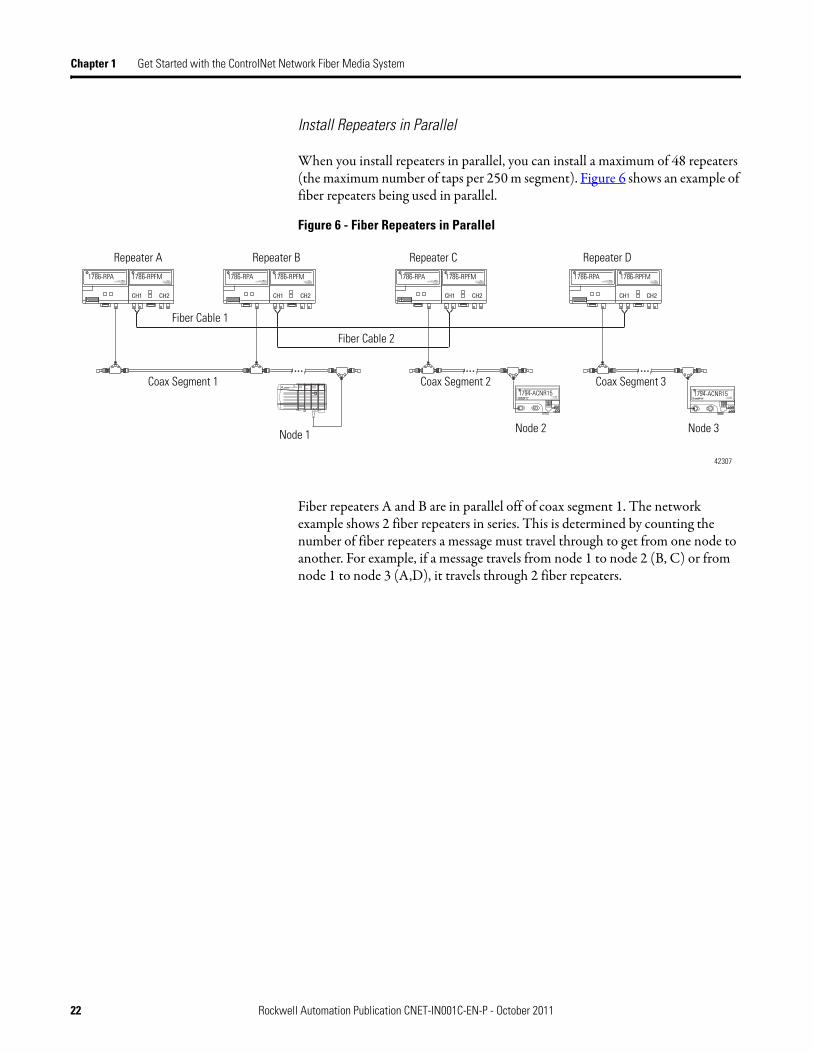
Install Repeaters in Parallel
When you install repeaters in parallel, you can install a maximum of 48 repeaters (the maximum number of taps per 250 m segment). Figure 6 shows an example of fiber repeaters being used in parallel.
Figure 6 - Fiber Repeaters in Parallel
Fiber repeaters A and B are in parallel off of coax segment 1. The network example shows 2 fiber repeaters in series. This is determined by counting the number of fiber repeaters a message must travel through to get from one node to another. For example, if a message travels from node 1 to node 2 (B, C) or from node 1 to node 3 (A,D), it travels through 2 fiber repeaters.
42307
Coax Segment 1 Coax Segment 2 Coax Segment 3
Node 1 Node 2 Node 3
Repeater A Repeater B Repeater C Repeater D1786-RPA 1786-RPA 1786-RPA 1786-RPA1786-RPFM 1786-RPFM 1786-RPFM 1786-RPFM
1794-ACNR15 1794-ACNR15
Fiber Cable 1
Fiber Cable 2
22 Rockwell Automation Publication CNET-IN001C-EN-P - October 2011

Get Started with the ControlNet Network Fiber Media System Chapter 1
Install Repeaters in a Combination of Series And Parallel
You can install repeaters in a combination of series and parallel connections. For mixed topologies (series and parallel) the maximum number of repeaters in series between any two nodes is 20.
• If you configure your network by using repeaters in combination of series and parallel, you need to count the repeaters in series on the worst-case path between any two nodes.
• There can be only one path between any two nodes on a ControlNet network link. Multiple repeater connections between two segments are not allowed.
Figure 7 - Repeaters in a Combination of Series and Parallel
In this network example, the maximum number of repeaters that a message will travel through is 5. The path is as follows: Node 1 to Node 4 travels through repeaters D, F, C, B, A. Repeaters D and E are in parallel, so you must consider the path of Node 2 to Node 4 through repeaters E, F, C, B, A. This secondary path is dependant on the fiber and coax lengths of Segment 1 and Segment 2, including Segment 7.
31509-M
Coax Segment 7
Repeaters D, E and F are installed in parallel
Repeater D
Coax Segment 1 Coax Segment 2 Coax Segment 3
Repeater E Repeater F
Node 1 Node 2 Node 3
Repeater A Repeater B Repeater C
Coax Segment 4 Coax Segment 6
Node 4 Node 6
Repeaters A, B, and C are installed in series and connected to the repeaters in parallel on segment 7 via Repeater F
Node 5
Coax Segment 5
Fiber Cable 1 Fiber Cable 2
FiberCable 3
* * *
* See Important on page 16
Rockwell Automation Publication CNET-IN001C-EN-P - October 2011 23

Chapter 1 Get Started with the ControlNet Network Fiber Media System
Install Repeaters in a Ring
Use this configuration to achieve an increased level of protection (in case ofcable failure) over a long distance (not available when you use traditionalcopper media). To achieve this increased level of protection, a fiber ring network transmits messages in the two directions of the ring (clockwise andcounter-clockwise).
In Figure 8, the path from node 1 to node 4 in a counter-clockwise direction is through 2 fiber repeaters (A, D). In a clockwise direction, the path from node 1 to node 4 is though 4 fiber repeaters (A, B, C, D). We refer to the longer path as the worst-case delay path.
Figure 8 - Fiber Repeaters in a Ring
The 1786-RPFRXL/B and 1786-RPFRL/B fiber repeaters automatically detect which message arrives first and disregards the other at each fiber repeater location. In the above example, the 1786-RPFRXL fiber repeater for node 4 would automatically detect the packet that arrives on a channel first, and disregard the second packet.
Node 1
Node 2
Node 3
Node 4
31237-M
1794-ACNR15 1786-RPA 1786-RPFRXL
1786-RPA
1786-RPA
1786-RPA
1786-RPFRXL
1786-RPFRXL
1786-RPFRXL
1794-ACNR15
1794-ACNR15
Repeater A
Repeater B
Repeater C
Repeater D
Fiber Cable 1
Fiber Cable 2
Coax Segment 1
Coax Segment 2
Coax Segment 3
Coax Segment 4
Fiber Cable 3
Fiber Cable 4
24 Rockwell Automation Publication CNET-IN001C-EN-P - October 2011

Get Started with the ControlNet Network Fiber Media System Chapter 1
A fiber-optic ring may contain up to 20 1786-RPFRL/B (long distance) or1786-RPFRXL/B (extra-long distance) fiber repeaters, depending onthe application.
Configure the Media in RSNetWorx for ControlNet Software
You can use RSNetWorx for ControlNet software to determine whether or not your system meets the network parameter requirements. Based on your system planned requirements (NUT, SMAX, UMAX, types and length of cable, number and types of repeaters and worst case network delay), RSNetWorx software will verify the network configuration parameters.
If RSNetWorx is unable to schedule the network due to errors, make the necessary changes. Changes might include inserting the correct media lengths and number of repeaters or increasing RPI, so the software can calculate the correct network parameters and download them to the keeper.
Set up the Network SMAX Parameter in RSNetWorx Software
You must properly set up the SMAX parameter in RSNetWorx for ControlNet software when used with the 1786-RPFRL or 1786-RPFRXL repeater module. The SMAX parameter sets the maximum scheduled node address on a ControlNet network. Refer to the documentation supplied with the RSNetWorx for ControlNet software.
You must set the SMAX parameter at least one node number higher than the highest-used scheduled node number. For example, on a network with 49 scheduled nodes (with 49 being the highest-used scheduled node number), you must set SMAX to at least 50. In this example, node number 50 is an unused scheduled node number.
For more information, see Getting Results with RSNetWorx for ControlNet, publication CNET-GR001.
IMPORTANT When used in a ring topology, redundant coaxial cabling (linear bus) or redundant rings are not allowed. Due to timing differences, the1786-RPFRXL/B and 1786-RPFRL/B fiber modules do not support redundant rings.
IMPORTANT When setting the SMAX parameter, you must allow one unused scheduled node address. This unused node address must be the highest available scheduled node number. Therefore, the maximum usable node address when using the 1786-RPFRL/B or 1786-RPFRXL/B module is 98.
Rockwell Automation Publication CNET-IN001C-EN-P - October 2011 25

Chapter 1 Get Started with the ControlNet Network Fiber Media System
Terminate Your Fiber Cable Be sure to use the correct connectors on the end of your fiber cable for the best optical and mechanical connections. For example, ST- and V-pin are the only two connectors that the ControlNet network recognizes.
See Table 8 on page 54 for more information on available connector kits for repeater modules.
You also want to use a dust cap on an unconnected terminated fiber cable end if a connector is not going to be used.
Test Your Fiber Media Connections and Segments
Many field testers are available to test the connectors on cable that is used with the 1786-RPFM, 1786-RPFRL/B and 1786-RPFRXL/B repeater modules. Consult with your fiber network specialist to determine which tester is the best for your media.
Power Your Repeaters The power for your fiber repeaters comes from the repeater adapters. The repeater adapters must be powered by using a 24V power supply.
See page 68 for the 1786-RPA/B repeater adapter installation instructions and power supply requirements.
Verify Your Network Verify whether your system meets the network parameter requirements.
1. In RSNetWorx for ControlNet software, go online, browse your network, and look for invalid node addresses.
2. OTDR and fiber field testers will help make sure that no segments violate distance constraints.
3. Make sure your network does not violate general network rules.
See Chapter 3, starting on page 43, for details.
4. Isolate a single segment of the network and verify its operation.
5. Connect multiple segments of the network , being mindful of bandwidth, insertion loss of the segment, and segment length.
6. Verify that the correct connectors and cable have been installed.
See page 55 for additional information.
26 Rockwell Automation Publication CNET-IN001C-EN-P - October 2011

Chapter 2
Topology and Signal Considerations
Develop a Plan Fiber-optic links in a ControlNet network system can do the following:• Increase network length beyond that supported by coax• Provide immunity to EMI• Provide better electrical isolation than standard coax cable
Fiber is strongly recommended to avoid lighting problems when connecting equipment in different buildings together.
You can create point-to-point, star, and ring configurations. Up to four fiber modules, with two fiber ports each, can be directly plugged to a repeater adapter. Multiple repeater adapters can be used to increase the number of fiber or coax connections.
Each port needs two fiber connections, one for receiving and another for transmitting signals. The basic configuration connects two coax segmentspoint-to-point by two repeater adapters and two fiber repeater modules, as illustrated in Figure 9.
Topic Page
Develop a Plan 27
Redundant Media 28
Topology Considerations 29
Coax Segment Constraints 30
Fiber Segment Constraints 31
Select a Module Type Based on Distance Requirements 31
Estimate Cable Lengths 33
Determine Attenuation Levels 35
Determine Propagation Delay 38
Rockwell Automation Publication CNET-IN001C-EN-P - October 2011 27

Chapter 2 Topology and Signal Considerations
Figure 9 - Basic Fiber Media Topology
This configuration is equivalent to the use of a coax repeater. Fiber cable can provide communication over longer distances than coax media.
Redundant Media Use redundant media when you need module and media redundancy. With redundant media, the channel-to-channel skew travel time difference must beless than 1.6 μs.
To keep skew time to a minimum, configure the cable paths on channels A and B in a similar manner as shown in Figure 10 on page 29.
Media redundancy can be achieved via a ring topology or linear bus topology. The 1786-RPFRL/B and 1786-RPFRXL/B fiber repeaters can provide media redundancy in a ring or linear bus topology, but not both. A redundant linear bus topology can be obtained by using the 1786-RPFS, 1786-RPFM, and1786-RPCD repeater modules. The planning phase should consider the advantages and disadvantages of using a ring or redundant linear bus topology.
Tap
Coax Segment 1
Fiber Repeater Module
30688-M
Fiber Repeater Module
Repeater Adapter
Repeater Adapter
Coax Segment 2
Terminator
Fiber Cable
TIP If you use a ring topology to provide media redundancy, you can connect to only one channel (A or B) of redundant port modules. ControlNet does not support mixed (linear and ring) redundancy in the same network. When using linear bus redundancy all ControlNet modules must have redundant ports (A and B) and must be connected throughoutthe network.
28 Rockwell Automation Publication CNET-IN001C-EN-P - October 2011

Topology and Signal Considerations Chapter 2
For redundancy, you should do the following on each channel:• Use the same number and types of repeater assemblies (repeater adapters
plus repeater modules)• Use the same type of cable• Keep cable lengths similar• If using redundant media in a linear bus topology, ring topologies are
not supported.
Figure 10 - Redundant Topology
Topology Considerations For best results, determine the constraints of your topology. For example, a maximum of 99 nodes are allowed on a network (98 nodes if you are usingring redundancy).
31420-M
Table 4 - Topology constraints
Constraint Example
Only one path is allowed between nodes (non-ring repeater modules only)
See Figure 7 on page 23.
In series topology, maximum of 20 repeaters in a series
In ring topology, up to 20 1786-RPFRL/B or 1786-RPFRXL/B modules per ring
See Figure 5 on page 21
See Figure 8 on page 24
Constraint of each coax segment (taps and trunk-cable sections)
See Figure 11 on page 30.
Constraint of each fiber segment application See page 31.
Power loss budget of each fiber segment See Table 5 on page 33.
Maximum propagation delay through the network See page 39.
Rockwell Automation Publication CNET-IN001C-EN-P - October 2011 29

Chapter 2 Topology and Signal Considerations
Coax Segment Constraints The total allowable length of a segment containing standard RG-6 quad shield coaxial cable depends upon the number of taps in your segment. There is no minimum trunk-cable section length requirement.
The maximum allowable total length of a segment is 1,000 m (3280 ft) with two taps connected. Each additional tap decreases the maximum length of the segment by 16.3 m (53 ft).
The maximum number of taps allowed on a segment is 48, with a maximum length of 250 m (820 ft).
Figure 11 - Maximum Segment Length (Using 1786-RG6 Coax Cable)
The data in Figure11 assumes you are using standard low-loss coax. High-flex cable may not support the distance versus the number of taps due to the higher loss factor associated with high-flex designs.
Example Coax Segment Constraint
For more information in the installation of a coax segment, see publication CNET-IN002, ControlNet Coax Media Planning and Installation Guide.
1000 (3280)
750 (2460)
500 (1640)
250 (820)
Maximum Allowable Segment Length =1000 m (3280 ft) - 16.3 m (53.4 ft) x [number of taps - 2]
Number of Taps
Segm
ent L
engt
h (ft
)
30014-m
AllowableRegion
2 16 32 64
500 (1640)
EXAMPLE If your segment requires 10 taps, the maximum segment length is:
1000 m (3280 ft) - 16.3 m (53.4 ft) x [10 - 2]
1000 m (3280 ft) - 130.4 m (427.2 ft) = 869.6 m (2852.8 ft)
The total trunk-cable length or number of taps can be increased by installing repeaters on the segment. This creates another segment.
The amount of high-flex RG-6 cable (catalog number 1786-RG6F) you can use in a system is less than the amount of standard RG-6 cable, so you should keep high-flex cable use to a minimum. Use BNC bullet connectors to isolate areas that require high-flex RG-6 cable from areas that require standard RG-6 cable; this allows the high-flex RG-6 section to be replaced before flexture life is exceeded.
30 Rockwell Automation Publication CNET-IN001C-EN-P - October 2011

Topology and Signal Considerations Chapter 2
Fiber Segment Constraints Every network that uses fiber repeaters must maintain a minimum signal level for each fiber segment in order to achieve an effective signal strength. Attenuation of a fiber segment is effected by the quality of the termination at each connector, splices, bulkheads, and the fiber cable. At any time, the total amount of attenuation shall not exceed the power budget of the type of repeater module that is being used.
Select a Module Type Based on Distance Requirements
When choosing a module type to use in a configuration, a commonly asked question is ‘Can I use a particular cable with a particular module?’ You must select a module (and the corresponding cable type) based on the distance you want to achieve.
There are two types of fiber cable supported: single and multi-mode. These two cable types differ in that single-mode cable allows light to travel in a single path. Multi-mode cable allows light to travel in multiple paths. Single-mode cable is generally used in longer distance applications.
Of these two types of cores, there are three configurations of cable commonly found in manufacturing environments:
• Simplex Cable• Duplex Cable• Multi-fiber Backbone Cable
All three cable configurations have either single- or multi-mode cores.
Simplex Cable
At each end, the cable is terminated with a connector appropriate to the type of fiber module to which the cable is attached.
IMPORTANT The attenuation values for connectors, splices, bulkheads, and cable are available in the manufacturer’s specifications for your products.
31506-M
Rockwell Automation Publication CNET-IN001C-EN-P - October 2011 31

Chapter 2 Topology and Signal Considerations
Duplex Cable
A duplex cable is made up of two jacketed fiber cores, with their jackets fused together to form a single cable. A duplex cable is sometimes called a zipcordfiber jumper.
Smaller lengths of simplex and duplex interconnect cable are typically directly connected between modules, or to a fiber panel within an enclosure.
Multi-fiber Backbone Cable
Multi-fiber backbone cable is composed of many fiber cores bundled into a jacketed cable. These cables are often run to a fiber panel within an enclosure. Smaller lengths of simplex or duplex interconnect cable are then typically used to connect from the fiber panel to individual modules or networks.
What is Zipcord?
The term ‘zipcord’ refers to any cable that is a duplex cable whereby the jacket is fused together to form a lamp cord-like cable that can be easily parted. The V-pin connector makes sure the fiber is reversed on opposite ends of the cable so that the Transmit end from one module is automatically connected to the Receive end of the other module.
Multiple lengths of zipcord (catalog number 1786-FSxx) are available for use with the 1786-RPFS module.
See page 65 for connection instructions.
31507-M
31508-M
32 Rockwell Automation Publication CNET-IN001C-EN-P - October 2011

Topology and Signal Considerations Chapter 2
Estimate Cable Lengths The maximum length of a fiber cable section for the fiber-optic modules is dependent on the quality of the fiber, number of splices, and the number of connectors.
If your distance requirements are less than 300 m, you can use a short-distance(single-mode) cable that comes pre-terminated for use with the 1786-RPFS fiber module. If your distance requirements are greater than 300 m, you must use a 1786-RPFM, 1786-RPFRL/B, or 1786-RPFRXL/B fiber module and terminate the cables in the field, or purchase pre-terminated cables from your supplier.
When estimating maximum cable length, take into account attenuation that occurs along the entire fiber path. Attenuation refers to the loss of light power as it passes through the cabling components.
Typically cable attenuation for multi-mode fiber at a wavelength of 1300 nm is less than 1.5 dB/km, and connection losses are 1 dB per connection.
Each Rockwell Automation fiber system has different constraints; therefore maximum fiber-optic cable lengths differ for each system. Rockwell Automation offers four different systems that are targeted to solve different applications:
• 1786-RPFS: Short-distance fiber system• 1786-RPFM: Medium-distance fiber system• 1786-RPFRL/B: Long-distance fiber system• 1786-RPFRXL/B: Extra-long distance fiber system.
Table 5 - Fiber Module Distance and Ratings
Module Typical Repeater Distance(1) Cable Type Optical Power Budget Connector Type
1786-RPFS 0…300 m 200/230 micron, single-mode 650 nm
4.2 dB V-pin
1786-RPM 0…3 km 62.5/125 µm, multi-mode1300 nm, graded index
13.3 dB ST (plastic or ceramic only; do not use metal connectors)
1786-RPFRL/B 0…10 km 62.5/125 µm, multi-mode1300 nm, graded index
15 dB
1786-RPFRXL/B 0…20 km 62.5/125 µm, multi-mode(2)
1300 nm, graded index10.5 dB
9/125 µm, single-mode(3)
1300 nm
(1) Entire network limited to 20 km max, per ControlNet network specifications.
(2) Although you can use multi-mode cable with the 1786-RPFRXL/B module, it is not recommended because achieveable distance is limited to 6.6 km.
(3) Also compatible with 62.5/125 µm, multi-mode cable.
IMPORTANT Avoid lengthening your cable by joining sections with connectors. Connectors can cause considerable attenuation and limit the maximum length of your system. Be sure to check the attenuation of different cable sections after the cable is installed.
Rockwell Automation Publication CNET-IN001C-EN-P - October 2011 33

Chapter 2 Topology and Signal Considerations
1786-RPFS Module
The 1786-RPFS (0…300 m) module specializes in solving short-distance applications. This system requires the use of pre-terminated cable assemblies. The total attenuation for a fiber cable section must be less than 4.2 dB.
200/230 Micron HCS (hard-clad silica) Fiber
Use 200 micron HSC cable with the 1786-RPFS module for short-distance applications. The 200 hcs cable is also known as a step index multi-mode type of fiber cable.
1786-RPFM Module
The 1786-RPFM (0…3 km) module is designed to solve medium-distance applications that require less than 3000 m per segment (9843 ft) between two ControlNet fiber repeaters. You must terminate medium-distance cable inthe field.
The maximum length of a section is dependent on the quality of the fiber, number of splices, and the number of connectors. The total attenuation for a cable section must be less than 13.3 dB.
62.5/125 Micron multi-mode OM1 Fiber
Use 62.5/125 micron cable with the 1786-RPFM, 1786-RPFRL/B, and1786-RPFRXL/B module for medium-distance applications. The OM1 cable isa graded index multi-mode type of fiber cable.
1786-RPFRL/B Module
The 1786-RPFRL/B (0…10 km) module is designed to solve long-distance applications that require up to 10,000 m (32,810 ft) between two ControlNet network devices. You must terminate long-distance cable in the field.
The maximum length of a section is dependent on the quality of the fiber, number of splices, and the number of connectors. The total attenuation for a cable section must be less than 15 dB.
62.5/125 Micron multi-mode OM1 Fiber
Use 62.5/125 micron cable with the 1786-RPFM, 1786-RPFRL/B, and1786-RPFRXL/B modules for long-distance applications. The OM1 cable is a graded index multi-mode type of fiber cable.
34 Rockwell Automation Publication CNET-IN001C-EN-P - October 2011

Topology and Signal Considerations Chapter 2
1786-RPFRXL/B (Fiber Ring or Point-to-Point) Module
The 1786-RPFRXL (0…20 km) module is designed to solve extra-long distance applications that require up to 20,000 m (65,620 ft) for single-mode fiber between two ControlNet network devices. You must terminate extra long-distance cable in the field.
The maximum length of a section is dependent on the quality of the fiber, number of splices, and the number of connectors. The total attenuation for a cable section must be less than 10.5 dB. This applies to single- ormulti-mode fiber.
62.5/125 Micron multi-mode OM1 Fiber
Use 62.5/125 micron cable with the 1786-RPFM, 1786-RPFRL/B, and1786-RPFRXL/B modules for extra-long distance applications. The OM1 cable is a graded index multi-mode type of fiber cable.
9/125 Micron single-mode OS1 Fiber
Use 9/125 micron with the 1786-RPFRXL/B module to achieve distances of up to 20 km. The OS1 cable is a graded index single-mode type of fiber cable.
Determine Attenuation Levels
You must calculate the power budget for you fiber cable. The short-distance fiber cable is pre-terminated; therefore the maximum attenuation level is 4.2 dB.
Once you start modifying the lengths of the segment, installing bulkhead or fusion splices, installing longer distances, exposing the cable to temperature ranges, or employing different quality cable and connector types, you must determine your attenuation levels. The following examples provide you with a place to start when you begin to determine your attenuation levels.
Attenuation Levels for a Short-distance Fiber Segment
The fiber cabling path loss can be verified by using the appropriate field test equipment. You must test the cable using the same wavelength as the specific fiber module in use.
The power budget for the short-distance fiber repeater module is 4.2 dB. This means that the maximum amount of attenuation between the two repeater modules shall not exceed 4.2 dB. This power budget is valid throughout the operating temperature range (0…60 C° (140 °F)).
Rockwell Automation Publication CNET-IN001C-EN-P - October 2011 35

Chapter 2 Topology and Signal Considerations
You can also affect the power budget by the quality of the connectors and fiber cable you choose. If you use a high-quality connector and fiber cable, you will be able to stretch your power budgets. Higher-quality connectors and cable can withstand a broader range of temperatures and distances.
In most situations you will not have to determine the attenuation levels forshort-distance fiber cable. The cable comes pre-terminated with connectors with the proper length of cable to be used under the maximum attenuation levels. If you modify the cables with splices then you must calculate the attenuation levels.
Figure 12 is an example of determining the maximum distance between two fiber repeaters. These are measured path losses, not theoretical. If the system attenuation exceeds the power budget, you will need to add additional repeaters.
Figure 12 - Maximum Distance Between Two Repeater Modules
Step 1: Total your loss budget
With the type of fiber module selected, how much total loss (dB) canyou have?
4.2 dB on the 1786-RPFS module
Step 2: Subtract loss for connectors
Select connectors. You need to account for at least two connectors per fiber cable segment.
Loss per connector x 2 connectors (1 at each end)
2 (1.5 dB) = 3 dB
31505-M
Connector 1 = Fiber Connector (Each Fiber Connector is 1.5 dB)
Fiber Cable 1 = Short Distance Fiber Cable Measured @ .1 dB)
Connector 1 + Fiber Cable 1 + Connector 2 = Total Attenuation1.5 + .1 + 1.5 = 3.1 dB
Connector 2 = Fiber Connector (Each Fiber Connector is 1.5 dB
36 Rockwell Automation Publication CNET-IN001C-EN-P - October 2011

Topology and Signal Considerations Chapter 2
Step 3: Subtract loss for cable lengths
Select fiber cable and identify loss = length of cable x (loss due tofiber cable/km)
Measured @ .1 dB
Step 4: Compare losses
Compare the sum of losses in steps 2 and 3, with total power budgetin step 1.
4.2 dB - 3 dB - .1 dB = 1.1 dB
If the sum of steps 2 and 3 are equal to or less than step 1 (which applies for our example), then you are within the power budget.
If steps 2 and 3 are greater than step 1, then you will need to reconfigure the topology, shorten cable lengths, or re-calculate the loss budget.
Attenuation Levels for Medium-distance Fiber Segments
The power loss budget for the medium-distance fiber repeater(catalog number 1786-RPFM) is 13.3 dB. The maximum amount of attenuation between the two fiber repeaters shall not exceed 13.3 dB. This powerloss budget includes the entire bulkhead/fusion splice.
This power loss budget is valid throughout the operating temperature range (0…60° C) of the 1786-RPFM module.
IMPORTANT Due to possible fiber connector degradation, it is recommended that an allowance of 0.5 …1.0 dB per short-distance fiber cable segment be added to the total attenuation. In the above example, the maximum cable length would be 20…70 meters.
There is no minimum length of cable for the short-, medium-, or long-distance fiber repeaters.
IMPORTANT Due to possible fiber connector degradation, it is recommended that an allowance of 1.0 dB per 62.5/125 multi-mode cable segment be added to the total attenuation.
There is no minimum length of cable for the short-, medium- or long-distance fiber repeaters.
Rockwell Automation Publication CNET-IN001C-EN-P - October 2011 37

Chapter 2 Topology and Signal Considerations
Attenuation Levels for Long-distance Fiber Segments
The power loss budget for the long-distance fiber repeater(catalog number 1786-RPFRL) is 15 dB. The maximum amount of attenuation between the two fiber repeaters shall not exceed 15 dB. This powerloss budget includes the entire bulkhead/fusion splice.
Attenuation Levels for an Extra-long Fiber Segment
The power loss budget for the extra-long distance fiber repeater (catalog number 1786-RPFRXL) is 10.5 dB. The maximum amount of attenuation between the two fiber repeaters shall not exceed 10.5 dB. This powerloss budget includes the entire bulkhead/fusion splice.
Determine Propagation Delay
The ControlNet network maximum propagation delay specification refers to the worst-case signal delay between any two nodes on a network. You need to figure out the worst-case scenario based on distances and the number of repeaters through which the signal has to travel.
Network delays include the delays through coax and fiber media, coax repeaters, repeater adapters, and fiber modules.
In order for a network to operate, the sum of the network’s delays must be equal to or less than the maximum propagation delay of 121 μs. The total network allowable delay each way is 121 μs.
Table 6 - Delay Values for ControlNet Network Media
ControlNet Network Items Delay Values
1786-RPCD 100 ns
1786-RPA/B 901 ns
1786-RPFS 94 ns
1786-RPFRL/B 420 ns
1786-RPFRXL/B 420 ns
1786-RPFM 153 ns
Coax cable 4.17 ns/meter
62.5/125 micron fiber 5.01 ns/meter
200 micron fiber
9/125 micron fiber
38 Rockwell Automation Publication CNET-IN001C-EN-P - October 2011

Topology and Signal Considerations Chapter 2
Maximum Propagation Delay Through a Network
Figure 13 is an example of a maximum propagation delay through a network.
Figure 13 - . Calculating the Delays
The example has the following maximum delay path from node 1 to node 2,end to end.
Delay Path 1: From controller to repeater adapter
Delay 1: 750 m coax cable x 4.17 ns/m = 3127 ns
Delay Path 2: 1786-RPCD module
Delay 2: Coax repeater; 901 ns (1786-RPA/B module) + 100 ns(1786-RPCD module) = 1001 ns
Delay Path 3: 1000 m of coax cable
Delay 3: 1000 m coax cable x 4.17 ns/m = 4170 ns
Delay Path 4: Fiber repeater; 1786-RPA/B module and 1786-RPFM module
Delay 4: Fiber repeater; 901 ns (1786-RPA/B module) + 153 ns(1786-RPFM module) = 1054 ns
31417-M
Delay 2 Delay 4 Delay 6 Delay 8
Delay 3
Delay 1
Delay 5 Delay 7
Channel A
Node 1Node 3 Node 2
750 m
1000 m3000 m 100 m
Delay 9
20 m 20 m
IMPORTANT Cable delays through taps are minimal and can be ignored.
Rockwell Automation Publication CNET-IN001C-EN-P - October 2011 39
Chapter 2 Topology and Signal Considerations
Delay Path 5: 3000 m of 62.5 micron fiber cable
Delay 5: 3000 m fiber cable x 5.01 ns/m = 15030 ns
Delay Path 6: Fiber modules; 1786-RPFM, 1786-RPA/B, 1786-RPFS modules
Delay 6: 153 ns (1786-RPFM module) + 901ns (1786-RPA/B module) + 94 ns (1786-RPFS module) = 1148 ns
Delay Path 7: 100 m of 200 micron fiber cable
Delay 7: 100 m fiber cable x 5.01 ns/m = 501 ns
Delay Path 8: Fiber modules; 1786-RPFS and 1786-RPA/B modules
Delay 8: 94 ns (1786-RPFS module) + 901 ns (1786-RPA/B module)= 995 ns
Delay Path 9: 20 m of coax cable
Delay 9: 20 m coax cable x 4.17 ns/m = 83 ns
Total delay = 27109 ns (27.1 μs)
This is a valid network because the calculated propagation delay of 27.1 μs isless than the maximum allowable propagation delay of 121 μs.
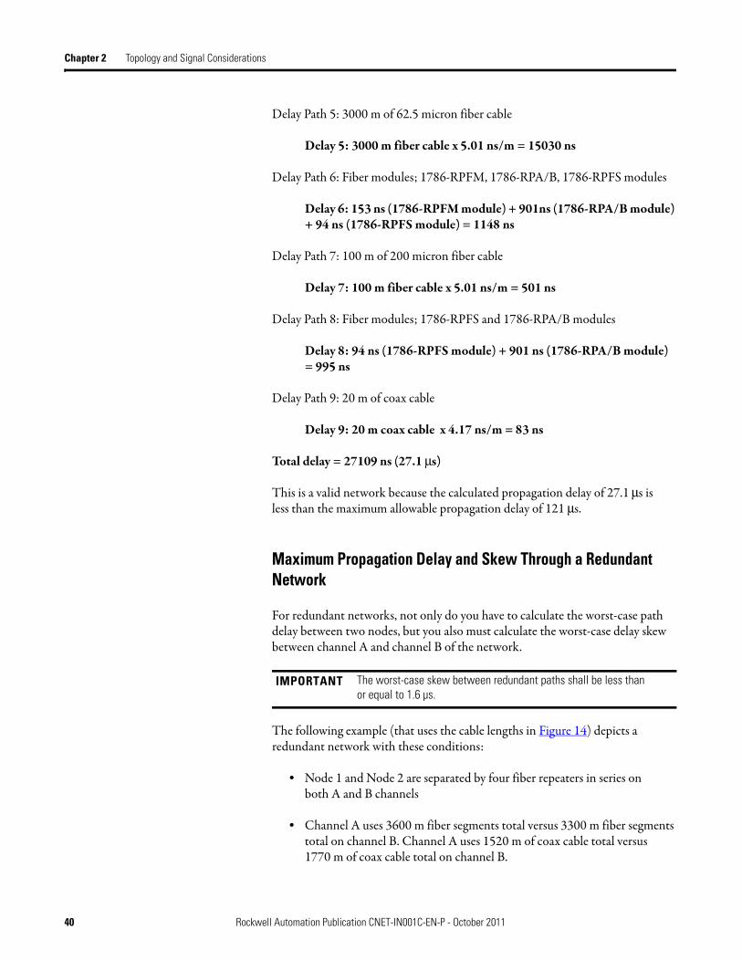
Maximum Propagation Delay and Skew Through a Redundant Network
For redundant networks, not only do you have to calculate the worst-case path delay between two nodes, but you also must calculate the worst-case delay skew between channel A and channel B of the network.
The following example (that uses the cable lengths in Figure 14) depicts a redundant network with these conditions:
• Node 1 and Node 2 are separated by four fiber repeaters in series onboth A and B channels
• Channel A uses 3600 m fiber segments total versus 3300 m fiber segments total on channel B. Channel A uses 1520 m of coax cable total versus1770 m of coax cable total on channel B.
IMPORTANT The worst-case skew between redundant paths shall be less thanor equal to 1.6 µs.
40 Rockwell Automation Publication CNET-IN001C-EN-P - October 2011
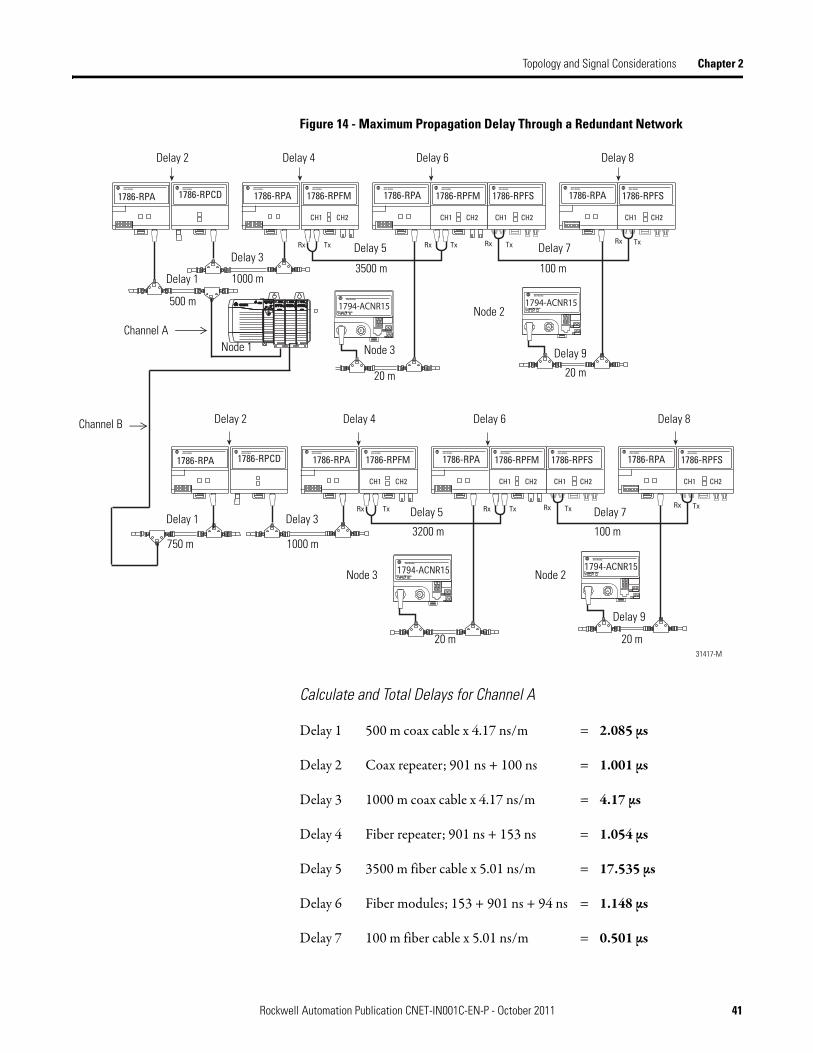
Topology and Signal Considerations Chapter 2
Figure 14 - Maximum Propagation Delay Through a Redundant Network
Calculate and Total Delays for Channel A
Delay 1 500 m coax cable x 4.17 ns/m = 2.085 μs
Delay 2 Coax repeater; 901 ns + 100 ns = 1.001 μs
Delay 3 1000 m coax cable x 4.17 ns/m = 4.17 μs
Delay 4 Fiber repeater; 901 ns + 153 ns = 1.054 μs
Delay 5 3500 m fiber cable x 5.01 ns/m = 17.535 μs
Delay 6 Fiber modules; 153 + 901 ns + 94 ns = 1.148 μs
Delay 7 100 m fiber cable x 5.01 ns/m = 0.501 μs
31417-M
Delay 2 Delay 4 Delay 6 Delay 8
Delay 1
Delay 3Delay 5 Delay 7
500 m
1000 m3500 m 100 m
20 m 20 m
Node 1 Node 3
Node 2
Delay 2 Delay 4 Delay 6 Delay 8
Delay 1 Delay 3 Delay 5 Delay 7
750 m 1000 m3200 m 100 m
Node 3 Node 2
Delay 9
Delay 9
20 m 20 m
Channel A
Channel B
Rockwell Automation Publication CNET-IN001C-EN-P - October 2011 41

Chapter 2 Topology and Signal Considerations
Delay 8 Fiber modules; 94 ns + 901 ns = 0.995 μs
Delay 9 20 m coax cable x 4.17 ns/m = 0.083 μs
Total delay for Channel A = 28.57 μs
Calculate and Total the Delays for Channel B
Delay 1 750 m coax cable x 4.17 ns/m = 3.127 μs
Delay 2 Coax repeater; 901 ns + 100 ns = 1.001 μs
Delay 3 1000 m coax cable x 4.17 ns/m = 4.17 μs
Delay 4 Fiber repeater; 901 ns + 153 ns = 1.054 μs
Delay 5 3200 m fiber cable x 5.01 ns/m = 16.032 μs
Delay 6 Fiber modules; 153 + 901 ns + 94 ns = 1.148 μs
Delay 7 100 m fiber cable x 5.01 ns/m = 0.501 μs
Delay 8 Fiber modules; 94 ns + 901 ns = 0.995 μs
Delay 9 20 m coax cable x 4.17 ns/m = 0.083 μs
Total delay for Channel B = 28.11 μs
Skew between channels =(Delay through A) – (delay through B) = 28.57 μs – 28.11 μs = 0.46 μs
This is a valid network because the calculated skew of 0.46 μs is less than the maximum allowable skew of 1.6 μs.
42 Rockwell Automation Publication CNET-IN001C-EN-P - October 2011

Chapter 3
Guidelines for Fiber-optic Installation
General Rules and Safety This section outlines specific rules and guidelines to follow when you installfiber-optic cable systems.
Warnings
Hire Fiber-optic Specialists for Installation and Certification
You may plan and install your fiber network or contract a fiber network engineer. It’s not necessary to have your fiber specialist connect your local equipment. Someone with media installation experience can connect local equipment by using pre-terminated interconnect cables that are purchased in their required lengths. Rockwell Automation offers the short-distance (<300 m) fiber cablepre-terminated as a kit for use with the 1786-RPFS module.
Topic Page
General Rules and Safety 43
Warnings 43
Types of Fiber Media Installations 45
ATTENTION: Follow these safety guidelines:
Safety glasses are required to protect your eyes when you handle chemicals and cut fiber. Pieces of glass fiber are very sharp and can easily damage the cornea of your eye.
Cleaved glass fibers are very sharp and can pierce the skin easily. Do not let cut pieces of fiber stick to your clothing or drop in the work area where they can cause injury later. Use tweezers to pick up cut or broken pieces of the glass fibers and place them on a loop of tape kept for that purpose alone. Keep your work area clean.
Laser light can damage your eyes. Laser light is invisible. Looking at it directly does not cause pain. The iris of the eye will not close involuntarily as when you view a bright light. Consequently, serious damage to the retina of the eye is possible. Should accidental eye exposure to laser light be suspected, get immediate medical attention.
Never look into a potentially active fiber with a microscope. Doing so can cause serious eye damage.
Rockwell Automation Publication CNET-IN001C-EN-P - October 2011 43

Chapter 3 Guidelines for Fiber-optic Installation
Single- and multi-mode pre-terminated fiber cables for medium, long, andextra-long distances also can be purchased that are made to order or off the shelf from your supplier. However, keep in mind that a fiber media installation must be certified and terminating longer distances in the field can be challenging. Trained specialists can select the correct type of fiber cable for your environmental and intrinsically safe area needs.
We recommend a trained specialist for installation of single- and multi-mode cables for the 1786-RPFM, (medium), 1786-RPFRL (long-distance), and1786-RPFRXL (extra long-distance) fiber modules.
The specialist you choose should install your cable and terminate it following the supplier’s installation instructions. The installation should include verification testing that provides segment length and loss at the appropriate optical wavelength. Verification should also provide pass/fail based on the limits defined in the fiber module users documentation or this manual.
Guidelines for Handling Fiber-optic Cable
These guidelines are designed to protect the safety of personnel who handlefiber-optic cable. The guidelines in Table 7 help establish an environment that allows for the best performance from your fiber-optic system.
ATTENTION: Do not look directly into the fiber ports. Light levels may cause damage to your eyesight. Do not view an active cable end through a fiber microscope.
Table 7 - Guidelines for Handling Fiber-optic Cable
Guideline Description
Minimum bend radius • Observe the minimum fiber cable bend radius specified.
Skin contact • Do not touch the ends of the fiber-optic strands. The fiber can break easily and pierce your skin.
Installation training • Train personnel on usage of the installation tools to place and terminate fiber cable. This would include training on hand-held tools, tension meters, optical power meters, cleaners, and adhesives.
Installation regulations • Observe all local regulations for installation, including personal safety equipment and the guidelines for its use.
44 Rockwell Automation Publication CNET-IN001C-EN-P - October 2011

Guidelines for Fiber-optic Installation Chapter 3
.
Types of Fiber Media Installations
You can use fiber media in many different application types. When you plan the application of fiber media, keep in mind the following installation types.
Pulled Application Guidelines
Pull fiber-optic cable prior to connector installation since it becomes more difficult to protect fiber from stress after connectors have been installed. Connectors may be pre-installed on one end, leaving the other end for pulling. Take precautions to protect ends from damage if the cable is pre-terminated. Refer to the manufacturer’s specifications for the fiber cable for additional information.
You must identify the strength member and the optical fiber location within the cable. Afterwards, a decision should be made to choose a cable pull method—pull or indirect attachment to ensure effective pulling without fiber damage. Never pull the cable by the fiber strand.
Direct Attachment
The cable strength member is attached directly to a pulling eye. Since epoxy glass central strength members are too rigid to tie, they may be secured to the eye by using tight clamping plates or screws.
Proper disposal • Always dispose of fiber waste in an approved container. Disposing of fiber waste prevents the contamination of clothes, fingers, or eyes of glass fragments. Do not leave pieces of fiber cable on your work surfaces.
Specifications • Review cable specifications for distances and required connectors.• Review all cable parameters and specifications before installation.
Make sure that you have the proper amount of connectors and installation equipment. Never attempt to use non-compatible connectors and installation tools.
Pulling tensions • Observe the maximum pulling tensions. Do not pull directly on fiber or force cable into a bend radius smaller than 20 times the cable diameter when under load and 10 times the cable diameter at no load. This will crack the glass and result in optical loss.
• Use a running line tension meter to determine the pulling tension applied during cable placement.
• Never allow tight loops, knots, kinks, or tight bends in the cable.• Entrance in and out of metal pull boxes must be smooth as not to
damage the cable sheath
ATTENTION: Do not leave any fiber pieces on your work surface. The glass is very small and can penetrate your skin easily.
Table 7 - Guidelines for Handling Fiber-optic Cable
Guideline Description
Rockwell Automation Publication CNET-IN001C-EN-P - October 2011 45

Chapter 3 Guidelines for Fiber-optic Installation
Indirect Attachment
Indirect attachment uses a pulling grip attached to the cable’s outer jacket to distribute the pulling force over the outer portion of the cable. The pulling grip produces the least amount of stress in cables where the strength member lies directly beneath the jacket.
Conduit and Duct Installation
Installation procedures for conduit and duct installation of fiber-optic cables are very similar to those of electrical wires. Avoid yanking, flipping, or wrapping cables causing unnecessary tightening. Fiber cable, electrical wires, or smallfiber-optic cables should never be subjected to foot traffic or potentiallycrushing forces.
Cables should be lubricated prior to pulling to minimize the pulling forces on the cables. Lubricants such as waxes, greases, clay slurries, and water-based gels are compatible with most fiber-optic jacket materials. Check with the fiber manufacture of your cable for the approved lubricants to be used on your cable.
Use this procedure for conduit or duct installation.
1. Attach the towline to the cable by using direct or indirect attachment as described in the previous section.
2. Establish two-way communication between the cable payoff station, intermediate hand assist stations, and the pulling station.
3. Use the following items for duct or cable tray replacements:• Adjustable lip clutch winch or equivalent• Tension monitoring system with continuous readout• Tow line that assures minimum friction• Dedicated inner duct, mainly for pulls in underground conduit• Cable end caps for use in flooded or unknown conduits and sealing
cable ends after placement
4. Position the cable reel and payoff frame for pulling.a. Mount the cable reel into the payoff apparatus so that the cable pays out
from the top of the reel.b. Attach the pulling grip to the cable and position the reel with its flanges
perpendicular to the floor or support foundation.c. Secure the payoff frame so it cannot move during pulling.
46 Rockwell Automation Publication CNET-IN001C-EN-P - October 2011

Guidelines for Fiber-optic Installation Chapter 3
5. Maintain enough slack on the cable as the pull starts to prevent the cable from contacting any equipment in the area.
Plan your pull to avoid a pull equaling or exceeding the total bends to 360° per pull. If it is not possible to avoid a pull of 360°, install an intermediate junction box within the 360° pull. Plan on manually handling the cable along the pull route to help limit the bends.
6. Position the winch at the pull station to avoid a steep angle either entering the duct or exiting the cable tray.
7. Leave enough extra cable to route to the equipment rack, put connectors on, and allow for future repairs when your pull is complete.
8. Cut off the pulling grip and the first 1 m (3 ft) of cable behind it.
9. Terminate the cable.
10. Measure and record the optical cable attenuation and length by using either an OTDR (optical time domain reflectometer) or an optical test.
11. Seal the ends of the cable with endcaps until they are terminated.
In some applications you may have to start your pull in the middle of a duct or conduit and pull in both directions. In this scenario, pull in the first direction by using the reel and payoff frame. In the other direction, lay out the cable in afigure-8 pattern on the floor. When the second pull begins, hand feed the cable into the duct system.
IMPORTANT Do not allow slack loops to form on the reel. Slack loops could cause a crossover and damage the cable. Always pull at slow speeds to limit the possibility of crossovers.
IMPORTANT Do not exceed the maximum pulling tension for your
fiber-optic cable.
IMPORTANT Be certain to clear the floor of dust, debris, and dirt before placing the cable on the floor.
Rockwell Automation Publication CNET-IN001C-EN-P - October 2011 47

Chapter 3 Guidelines for Fiber-optic Installation
Aerial Installation
Most round, tight buffer, and loose-tube optical cables are compatible with helical lashing, clamping, and tied mounting. These cables can be used in aerial installations by using methods similar to those for electrical cables.
The following procedure describes the stationary method for aerial cable installation.
1. Use the following tools for aerial placement:• Adjustable lip clutch winch or equivalent• Tension monitoring system with continuous readout• Tow line that assures minimum friction over cable blocks• A payoff apparatus equipped with a breaking system. The breaking
system can be used to place light tension on the cable during placement.
2. Mount the cable reel into the payoff apparatus so that it pays out fromthe top.
3. Determine the direction to pull your cable.• Pull the cable up-grade whenever possible• Place the payoff apparatus on an even surface and in-line with the
support strand whenever possible
4. Place cable blocks along the support strand at a distance of no greater than 15 m (50 ft) apart. The first cable block should be placed as close to the initial pole as possible.
5. Place additional cable blocks:• One on each side of a corner• Where distinct vertical clearances are required
6. Guide the cable to a position parallel with the strand as it approaches the payoff by securing the cable guide to a strand by using a guy clamp on the strands behind the first roller.• Place the cable 0.6 m (2 ft) past the pole if the cable should start at a
dead end pole• Place the first cable block within 0.3 m (1 ft) if the pull starts midstrand
between poles
IMPORTANT Aerial cable must be properly supported using ‘J’ hooks or loops of wire of sufficient diameter not to damage the fibers due to loading.
IMPORTANT Do not drag fiber-optic cable across or around any obstacles that may cause outer jacket abrasion.
IMPORTANT Use manila rope (1/4-in., min), kevlar rope, capstan winch rope, or coated line winch rope as a cable towline.
48 Rockwell Automation Publication CNET-IN001C-EN-P - October 2011

Guidelines for Fiber-optic Installation Chapter 3
7. Place a one-sheave cable block or snatch block within 0.3 m (1 ft) of the pole at the end of the pull. Make sure the winch is positioned to avoid steep angles exiting the block.
8. Thread the towline through the all of the cable blocks and the cable guide to the end of the cable for aerial placement.
9. Attach the towline to the cable by using direct or indirect attachment as your application dictates.
10. Establish communications between the cable payoff station, intermediate hand assist stations, and the pulling station.
11. Pull the cable slowly by using the towline and winch.
12. Reverse the payoff reel by hand to rework any excessive sag between guide blocks after the pull is completed and the pulling end is anchored. Use the payoff break to maintain the proper tension.
13. Measure and record the optical cable attenuation and length by using either an OTDR (optical time domain reflectometer) or an optical test.
14. Tighten the strand suspension clamps at the poles where the cable is tobe lashed.
15. Lashing should begin immediately after the cable has been placed.
16. Pull the lasher toward the cable reel.
Always take up the slack of the unlashed spans by reversing the payoff reel slowly by hand.
17. Remove the cable blocks as the lasher progresses towards the payoff reel.
18. Secure the strand wire to keep it from loosening on the previously lashed span as the lasher is transferred from strand to strand.
19. Proceed with the lasher until each lash is complete.
20. Leave enough extra cable to route to the equipment rack, put connectors on, and allow for future repairs when your pull is complete.
21. Seal the ends of the cable with endcaps until they are terminated.
IMPORTANT Do not exceed the maximum pulling tension as specified by the manufacturer of your cable.
Rockwell Automation Publication CNET-IN001C-EN-P - October 2011 49

Chapter 3 Guidelines for Fiber-optic Installation
Direct Burial Installation
Some applications call for a direct burial installation. Direct burial installation requires some special considerations that aren’t necessary for other pulled applications. These guidelines are designed to prevent hazards such as freezing water, crushing forces, ground disruption from construction, and rodents.
Use the following guidelines to help you plan your direct burial installation.
• Use cable specifically designed for direct burial.
• Use heavy duty armor cables buried directly into the ground.
• Bury the cable between 1…1.2 m (36…48 in.) deep.
• Use gel filling, metal sheathing, and armoring when possible.
• Use loose-tube cable constructions where uneven pulling forces area problem.
Open Trench Installation
Use these steps as a guide for installing fiber-optic cable by using an opentrench method.
1. Maintain minimum tension on the cable as it rolls over the guide rollers and through the guide shoot.
2. Consider methods of placement like boring or creating a conduit when your installation intersects with objects like streets, sidewalks, or landscaping.
3. Maintain at least a 1 m (39 in.) separation when your fiber-optic cable is placed in proximity to an existing power cable.
4. Use some form of mechanical protection (steel pipe, cement conduit, and so forth) when adequate earth cover cannot be maintained inyour application.
IMPORTANT Do not pull the cable in excess of its maximum allowable installation tension as specified in the cable manufacturer’s specifications.
50 Rockwell Automation Publication CNET-IN001C-EN-P - October 2011

Guidelines for Fiber-optic Installation Chapter 3
5. Use the following procedure if you must start cable placement in the middle of a selected trenching route.a. Pull in the first direction until the end point is reached.b. Remove the cable for the opposite direction from the reel by hand and
carefully coil it on the ground in a figure-8 pattern.
c. Hand guide the cable in the second direction as the pull begins.
6. Begin cable placement as soon as possible after trenching.
You can avoid possible collapse and fill of your trench by filling it as soon as possible. Depending on your application, you may want to use a trencher with a mobile cable trailer and payoff.
7. Be certain that your cable trailer has properly sized rollers and an adjustable breaking system.
8. Backfill over the cable as soon as possible after cable placement.
Consult your local ordinances for guidance on backfilling and trenching procedures.
9. Avoid backfilling with materials like frozen earth, rocks and boulders, construction debris, and so forth.
These objects could create point discontinuity along the buried cable and harm the cable’s performance.
10. Machine tap any areas where trenching could be threatened by erosionor washout.
11. Measure and record the optical cable attenuation and length by using either an OTDR (optical time domain reflectometer) or an optical test.
12. Seal the ends of the cable with endcaps until they are terminated.
IMPORTANT Be certain to place the cable in a manner that will prevent the cable from binding against foliage, rocks, or other impediments.
IMPORTANT Do not allow fiber-optic cable to be pinched, braided, or bent back during payoff from the cable trailer. Do not exceed the cable’s minimum bend radius and tension. You may even want to guide your cable into the trench by hand.
Rockwell Automation Publication CNET-IN001C-EN-P - October 2011 51

Chapter 3 Guidelines for Fiber-optic Installation
Vertical Installation
The requirements of your application may require a vertical installation. You can install fiber-optic cable vertically in trays, shafts, or towers. Dielectric cables are recommended for applications requiring high vertical installations, radio towers for example.
Use the following guidelines when planning a vertical cable installation.
1. Clamp cable to give extra support in preventing ice loading and wind slapping.
Your specific environment will determine where you should clamp your cable. Clamping intervals can be as short as 1 m (3 ft) and as long as15…30 m (50…100 ft) in interior locations.
Cables in vertical cable shafts are generally clamped directly to the walls of the shaft.
Cables installed in elevator shafts are usually supported by suspension strands and suspended from the top of the shaft. The suspension strand is attached to the wall at frequent intervals and at the bottom of the shaft. Consult your local codes and practices for installation in an elevator shaft.
2. Avoid downward migration of cable in loose-tube constructions by looping the cable approximately 0.3 m (1 ft) in diameter at the top, bottom, and every 150 m (500 ft).
In loose-tube constructions cable may migrate downward creating crowding at the bottom. The crowding may cause an increase in attenuation, especially in below freezing temperatures.
3. Plan cable runs that keep bends to a minimum.
4. Drill all holes for the entire run larger enough to accommodate steel sleeves when passing cables through walls and floors.
The inside diameter of steel sleeves should be 4 times the diameter of the cable. The minimum diameter of a steel sleeve is 5 cm (2 in.).
Steel sleeves are required to run cable through a firewall. Consult your local codes and practices for installations through firewalls.
5. Measure and record the optical cable attenuation and length by using either an OTDR (optical time domain reflectometer) or an optical test.
6. Seal the ends of the cable with endcaps until they are terminated.
52 Rockwell Automation Publication CNET-IN001C-EN-P - October 2011

Chapter 4
Terminate Your Fiber-optic Cable
What Is Termination? Termination is the process of attaching a connector to the ends of your fiber cable. Use protective caps on the ends of unused connectors.
Follow these additional recommendations to terminate your fiber cable:• Decide on the type of cable dressing based on the fiber cable construction
(for example, loose tube, zipcord, simplex, and so forth)See page 31 for more information.
• Decide if a patch panel is to be used– A loose tube cable should be terminated into a patch panel– Jumpers should be used to connect the segment from the patch panel to
the fiber repeater; determine the jumper lengths for the patch panel• Route fiber cable in the cabinet appropriately• Provide sufficient cable length for maintenance and determination if it
becomes necessary to re-terminate the fiber ends• ST-type terminations must be plastic or ceramic; no metal
Figure 15 - Patch Panel Example
Figure 15 shows a patch panel with incoming multi-fiber backbone cable and connectors for interconnect cables.
Topic Page
What Is Termination? 53
Terminate Your Cable 54
30690
Rockwell Automation Publication CNET-IN001C-EN-P - October 2011 53

Chapter 4 Terminate Your Fiber-optic Cable
Terminate Your Cable Most connector manufactures offer connector termination systems that are specific to the connector. We recommend that the termination kit be purchased from the same manufacture.
There are two types of connector systems in the market:
• One common type is fast termination where the cable end is prepared and inserted into the back end of the connector. The system then locks the cable and fiber in place. This type uses an index matching gel so no fiber polishing is needed.
• Other connector termination systems require polishing and are more difficult to use.
You must decide which connector system is appropriate for your needs.
Table 8 details the connector types that fiber repeaters use in theControlNet network.
Follow these general instructions when terminating fiber cable.
1. Organize your termination kit materials.
2. Reference your plan to be certain that you have enough supplies to make the fiber connections and to terminate all used fiber cable ends.
3. Follow the assembly and safety procedures for your termination kit.
4. Place a dust cap (supplied in fiber cable kits) on the end of the connector.
Table 8 - Termination Kits
Fiber Module Kit Types
1786-RPFS V-Pin pre-terminated and commercially available field termination kits are available.
1786-RPFM1786-RPFRL
ST, and MM connector pre-terminated or commercially available field terminations kits are available.
1786-RPFRXL ST, SM, and MM connector pre-terminated or commercially available field termination kits are available.
ATTENTION: Do not let the ends of a fiber-optic strand come into contact with dust, dirt, or other contaminants. Clean contaminated ends with a soft, clean, lintless cloth and alcohol.
Always attach protective caps onto fiber cable connectors and fiber ports when they are disconnected.
54 Rockwell Automation Publication CNET-IN001C-EN-P - October 2011

Chapter 5
Verify Your Network
Set Network Parameters You can use RSNetWorx for ControlNet software to determine if network parameters are set up correctly. Based on the system parameters you entered, such as, NUT, SMAX, UMAX, and worst-case network delay, RSNetWorx software calculates scheduled messaging for your network.
If your network is not valid, you must adjust your parameters.
For more information, see Getting Results with RSNetWorx for ControlNet, publication CNET-GR001.
Measure Power Loss After you install short-, medium- or long-distance fiber cable, check your sections by using an optical power meter to verify that your attenuation is less than or equal to the maximum allowed by the fiber type. The light source you are using must match the wavelength of the fiber module in use.
See Table 9 on page 56 for the wavelengths of each module.
The power loss measurement should match the tables in Chapter 2. If you do not follow the cable insertion loss recommendations in Table 5 on page 33, you can assume that you will have high-loss cable and high-loss connections.
Topic Page
Set Network Parameters 55
Measure Power Loss 55
OTDR Measurement 57
Rockwell Automation Publication CNET-IN001C-EN-P - October 2011 55

Chapter 5 Verify Your Network
Do not test the cable with the wrong power source because you will get inaccurate readings. The power budgets are at the source wavelengths.
Verify each segment length by using an optical time domain reflectometer (OTDR) field tester or by using the markings on the cable jacket.
See page 57 for more information.
Optical power meters transmit a light source at one end of your cable with an optical power meter at the other end of the cable. You can read the attenuation or power from the power meter to confirm the attenuation of your section.
See Table 5 on page 33 for module distance ratings.
Incorrect Loss Measurement Example
If you are testing a single-mode or multi-mode cable with a 640 nm light source, you will get an incorrect loss measurement. You must test the fiber at 1300 nm to match the cable rating.
Always record and maintain records for attenuation levels for each cable section strand. The attenuation records are valuable tools for troubleshooting and maintaining your network.
Table 9 - Fiber Operation Wavelengths
Module Wavelength
1786-RPFS 650 nm
1786-RPFM 1300 nm
1786-RPFRL/B
1786-RPFRXL/B
Power source must match the cable segment you are testing.
Power Meter
56 Rockwell Automation Publication CNET-IN001C-EN-P - October 2011

Verify Your Network Chapter 5
Considerable power loss in your cable could be a result of thefollowing conditions:
• Poor splices• Improper bend radius• Bending losses• Broken fibers• Poor connections• Contaminated or damaged connectors• High fiber bend radius • Poorly polished connector
OTDR Measurement In addition to power loss measurement, you should examine your total fiber network by using an optical time domain reflectometer (OTDR). The OTDR emits light into a strand of fiber optic cable and displays the reflected light.
OTDR tests provide the following measurements that will help you troubleshoot and maintain your network.
• Total distance along the cable to a fiber break• Distance to an event (splice, bend, connector) that attenuates the light• Distance between two attenuating events• Light attenuation between two points of the cable• Total reflected light or light reflected from a single event
Keep records of the traces for each cable strand on either hard copy orcomputer backup.
IMPORTANT Disconnect the fiber modules from the fiber cables before performingan OTDR test.
Rockwell Automation Publication CNET-IN001C-EN-P - October 2011 57

Chapter 5 Verify Your Network
Notes:
58 Rockwell Automation Publication CNET-IN001C-EN-P - October 2011

Appendix A
Install Your Fiber Repeater Modules and Repeater Adapters
Installation Guidelines Use these guidelines when you install your fiber repeater modules and repeater adapters.
• Observe the environmental specifications for the fiber units as outlined in each installation instruction.
• Avoid electrostatic and electromagnetic fields at installation sites.
• Avoid corrosive and inflammable gases, dust, conductive particles, oil mist, and organic solutions when choosing an installation site.
• Prevent equipment exposure to water or direct sunlight.
• Mount the units in a NEMA-rated enclosure based on the environmental protection for where the units are being installed.
Fiber repeater modules are IP20 components. IP means Ingress Protection, a rating based on the IEC 60529 standard to determine the strength of an enclosure for electrical equipment.
Topic Page
Installation Guidelines 59
Mount the Fiber Module 60
Connect a 1786-RPFS Module 65
Connect Fiber Repeater Modules 66
Wire a Repeater Adapter Module 68
Troubleshoot the Module 69
Specifications for Fiber-optic Cable 70
IMPORTANT Because two paths to the same nodes are not allowed, do not make a fiber or copper connection between modules that are connected to the same repeater adapter.
Rockwell Automation Publication CNET-IN001C-EN-P - October 2011 59

Appendix A Install Your Fiber Repeater Modules and Repeater Adapters
• Allow a minimum of 5 cm from surrounding equipment forproper ventilation.
• To maintain proper ventilation, do not mount the repeater modulesupside down.
• Use zinc-plated yellow-chromate-steel DIN rails to prevent corrosion.
Mount the Fiber Module The following steps are generic for mounting a module. Refer to the documentation with the repeater adapters and modules for specificinstallation information.
1. Position the module at a 30° angle.
2. Hook the lip on the rear of the module onto the top of the DIN rail, and rotate the module onto the rail.
3. Press the module onto the DIN rail until flush.
TIP Horizontal mounting is preferred. Vertical mounting is allowed. We recommend that the 1786-RPA/B module be mounted at the top if vertical mounting is chosen.
ATTENTION: Never install a 1786-RPCD repeater module to the right of a 1786-RPFRL/B or 1786-RPFRXL/B fiber repeater module on the same DIN rail. The1786-RPCD repeater module will not operate properly. Install the 1786-RPCD repeater module to the left of a 1786-RPFRL/B or 1786-RPFRXL/B fiber repeater module.
ATTENTION: This product is grounded through the DIN rail to chassis ground. Use a zinc-plated yellow-chromate-steel DIN rail to assure proper grounding. The use of other DIN rail materials (for example, aluminum or plastic) that can corrode, oxidize, or are poor conductors, can result in improper or intermittent grounding. Secure DIN rail to mounting surface approximately every 200 mm (7.8 in.) and use end-anchors appropriately.
42542
60 Rockwell Automation Publication CNET-IN001C-EN-P - October 2011

Install Your Fiber Repeater Modules and Repeater Adapters Appendix A
The locking tab should snap into position and lock the module to theDIN rail.
4. If necessary, remove the protective caps from the transmit and receivefiber channels.
TIP Use a screwdriver to move the locking tab downward, if the module is not secured.
WARNING: Removal and insertion under power (RIUP) is not supported. These modules must be powered down while connecting and disconnecting them from any interconnected modules.
If you insert or remove the module while backplane power is on, an electrical arc can occur. This could cause an explosion in hazardous location installations.
Be sure that power is removed or the area is nonhazardous before proceeding.
If Then
You will use a channel Remove the protective cap from the channel.
You will not use a channel Keep the protective cap on to protect the channel from dust.
You place the module in storage
42543
41900
Protective Cap
DIN Rail
ProtectiveBackplane Cap
Both sides of the module contain a backplane connector.
Rockwell Automation Publication CNET-IN001C-EN-P - October 2011 61
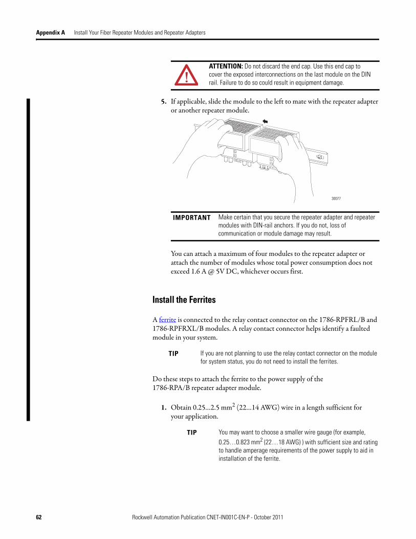
Appendix A Install Your Fiber Repeater Modules and Repeater Adapters
5. If applicable, slide the module to the left to mate with the repeater adapter or another repeater module.
You can attach a maximum of four modules to the repeater adapter or attach the number of modules whose total power consumption does not exceed 1.6 A @ 5V DC, whichever occurs first.
Install the Ferrites
A ferrite is connected to the relay contact connector on the 1786-RPFRL/B and 1786-RPFRXL/B modules. A relay contact connector helps identify a faulted module in your system.
Do these steps to attach the ferrite to the power supply of the1786-RPA/B repeater adapter module.
1. Obtain 0.25…2.5 mm2 (22…14 AWG) wire in a length sufficient foryour application.
ATTENTION: Do not discard the end cap. Use this end cap to cover the exposed interconnections on the last module on the DIN rail. Failure to do so could result in equipment damage.
IMPORTANT Make certain that you secure the repeater adapter and repeater modules with DIN-rail anchors. If you do not, loss of communication or module damage may result.
TIP If you are not planning to use the relay contact connector on the module for system status, you do not need to install the ferrites.
TIP You may want to choose a smaller wire gauge (for example, 0.25…0.823 mm2 (22…18 AWG) ) with sufficient size and rating to handle amperage requirements of the power supply to aid in installation of the ferrite.
30077
62 Rockwell Automation Publication CNET-IN001C-EN-P - October 2011
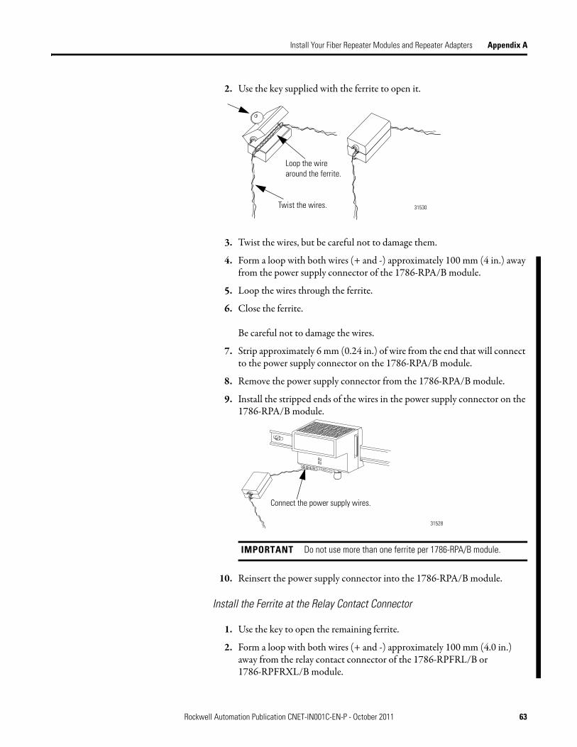
Install Your Fiber Repeater Modules and Repeater Adapters Appendix A
2. Use the key supplied with the ferrite to open it.
3. Twist the wires, but be careful not to damage them.
4. Form a loop with both wires (+ and -) approximately 100 mm (4 in.) away from the power supply connector of the 1786-RPA/B module.
5. Loop the wires through the ferrite.
6. Close the ferrite.
Be careful not to damage the wires.
7. Strip approximately 6 mm (0.24 in.) of wire from the end that will connect to the power supply connector on the 1786-RPA/B module.
8. Remove the power supply connector from the 1786-RPA/B module.
9. Install the stripped ends of the wires in the power supply connector on the 1786-RPA/B module.
10. Reinsert the power supply connector into the 1786-RPA/B module.
Install the Ferrite at the Relay Contact Connector
1. Use the key to open the remaining ferrite.
2. Form a loop with both wires (+ and -) approximately 100 mm (4.0 in.) away from the relay contact connector of the 1786-RPFRL/B or 1786-RPFRXL/B module.
IMPORTANT Do not use more than one ferrite per 1786-RPA/B module.
Loop the wire around the ferrite.
Twist the wires. 31530
Connect the power supply wires.
31528
Rockwell Automation Publication CNET-IN001C-EN-P - October 2011 63

Appendix A Install Your Fiber Repeater Modules and Repeater Adapters
3. Loop the wires through the ferrite.
4. Close the ferrite.
Be careful not to damage the wires.
5. Strip approximately 6 mm (0.24 in.) of wire from the end that will connect to the relay contact connector on the 1786-RPFRL/B or 1786-RPFRXL/B module.
6. Remove the relay contact connector from the 1786-RPFRL/B or1786-RPFRXL/B module.
7. Install the stripped ends of the wires in the relay contact connector on the fiber repeater module as shown below.
8. Reinsert the relay contact connector into the 1786-RPFRL/B or1786-RPFRXL/B module.
9. Connect the fiber cable as described on page 66.
10. If you plan not to use a channel, attach a small section of fiber cable (or a Simplex fiber loop) between the Receive port (RX) and the Transmit port (TX) of any unused fiber port to create a jumper.
Although not required for module operation, the jumper turns the status indicators green and prevents the relay contact connector from opening and indicating a failure.
Connect the ferrite here.
31531-M
64 Rockwell Automation Publication CNET-IN001C-EN-P - October 2011

Install Your Fiber Repeater Modules and Repeater Adapters Appendix A
Connect a 1786-RPFS Module
The 1786-RPFS module requires a pre-terminated zipcord wiring kit. The kits are offered in a variety of lengths. Consult with your local distributor for attenuation specifications before you purchase your fiber media components.
The zipcord uses a duplex cable that contains two separate fibers, one for transmit and one for receive. If you are wiring only one channel, you can use eitherchannel 1 or channel 2.
1. Hold down the latch and insert the channel 1 zipcord connector into theA and B connectors until the pins and latch lock into place.
Make certain you insert the blue pin, receive, of the zipcord connectorin A and the black pin, transmit, into B.
2. Hold down the latch and insert the other end of the duplex cable into another module by using either channel 1 or channel 2 of theother module.
IMPORTANT The duplex cable is manufactured with the fiber reversed on opposite ends. This automatically connects channel A of one unit to channel B of the other. Do not connect more than one duplex fiber or two simplex fibers between the same modular repeaters, even if they are from different modules on the same repeater.
See page 66 for using a tracer on a duplex cable.
30079
Channel 1, A and B
Channel 2, A and B
Rockwell Automation Publication CNET-IN001C-EN-P - October 2011 65

Appendix A Install Your Fiber Repeater Modules and Repeater Adapters
Connect Fiber Repeater Modules
This section describes how to connect cables for fiber repeater modules (other than the 1786-RPFS; see page 65). A tracer on a duplex cable helps to identify and follow the cable throughout your system. A tracer is one of the two wires on the duplex cable that is one of the following:
• Printed with the cable legend• Ribbed
Connect the cable between the fiber modules by making a simple crisscross connection. To do this, you will connect the cables between modules from the receive (RX) end of one channel to the transmit (TX) end of the other module, as shown in the following diagram.
Do these steps to connect the cable.
1. Use the tracers on the cable to identify which cable is connected to the receive (RX) port and which one to the transmit port (TX).
2. Connect the receive port (RX) and transmit port (TX) at thestarting module.
3. Do the following to attach the cable connector to the module connector.
a. Align the key of the cable connector with the slot in the module connector, and insert the connector into the RX port.
b. Push and twist the locking cap until the bayonet lug is locked into place.
TIP Channels 1 and 2 on the module are identical. Channel 1 of a module can be connected to either channel of another module.
TX TXRXRX
42550
66 Rockwell Automation Publication CNET-IN001C-EN-P - October 2011

Install Your Fiber Repeater Modules and Repeater Adapters Appendix A
4. At the second module, connect the cables in reverse.
For example, tracer to TX port on module 1, non-tracer to RX port on module 1: tracer to RX port on module 2, non-tracer to TX porton module 2.
Terminate the Cable
Termination is the process of attaching connectors to the ends of fiber cable. Follow these general instructions when terminating fiber cable.
1. Organize your termination kit materials.
2. Reference your plan to be certain that you have enough supplies to make the fiber connections and to terminate all used fiber cable ends.
3. Make a schedule for performing the connections.
4. Follow the assembly and safety procedures for your termination kit.
5. Place a dust cap (supplied in fiber cable kits) on the end of the connector.
ATTENTION: Do not look directly into the optical port to avoid damage to your eyes.
ATTENTION: Safety glasses are required to protect your eyes when you handle chemicals and cut fiber. Pieces of glass fiber are very sharp and can easily damage the cornea of your eye.
Cleaved glass fibers are very sharp and can pierce the skin easily. Do not let cut pieces of fiber stick to your clothing or drop in the work area where they can cause injury later. Use tweezers to pick up cut or broken pieces of the glass fibers and place them on a loop of tape kept for that purpose alone. Keep your work area clean.
IMPORTANT Be certain to follow the instructions that are provided by your fiber termination kit manufacturer.
ATTENTION: If this equipment is used in a manner not specified by the manufacturer, the protection provided by the equipment may be impaired.
Rockwell Automation Publication CNET-IN001C-EN-P - October 2011 67

Appendix A Install Your Fiber Repeater Modules and Repeater Adapters
Wire a Repeater Adapter Module
This section describes how to wire a repeater adapter module.
Follow these steps to wire the module.
1. Strip about 7 mm (0.28 in.) of insulation from the end of each wire.
2. Attach the Vin + wire to one of the Vin + terminals on the RTB.
Tighten the screws to 0.6…0.8 N•m (5…7 lb•in).
3. Attach the Vin - wire to one of the Vin - terminals on the RTB.
Tighten the screws to 0.6…0.8 N•m (5…7 lb•in).
4. Install the removable terminal block (RTB) onto the repeateradapter module.
Tighten the screws to 0.6…0.8 N•m (5…7 lb•in).
WARNING: An electrical arc can occur under these circumstances:
- When you connect or disconnect the removable terminal block (RTB) with field side power applied
- If you connect or disconnect the communication cable with power applied to this module or any device on the network
This could cause an explosion in hazardous location installations. Be sure that power is removed or the area is nonhazardous before proceeding.
TIP Make sure you have obtained the following items before you begin to wire the module:
• Two lengths of 0.21…3.3 mm2 (24…12 AWG) wire
• Wire stripping tool
• Small, flathead screwdriver
TIP The unused Vin + and Vin - terminals can be used to supply power to other devices.
Vin + and Vin - Terminals
31456-M
68 Rockwell Automation Publication CNET-IN001C-EN-P - October 2011

Install Your Fiber Repeater Modules and Repeater Adapters Appendix A
5. Connect the repeater adapter module to the ControlNet network by connecting the drop line of the coax tap to the BNC connector.
6. Terminate any unused coax ports by connecting a 75 Ω terminator to the unused BNC connector.
One 75 Ω terminator is shipped with the repeater adapter module.
Troubleshoot the Module Use the channel 1 or channel 2 status indicators to check module status and troubleshoot the module.
For status indicator descriptions, see page 73.
31459-M
BNC Connector
Rockwell Automation Publication CNET-IN001C-EN-P - October 2011 69
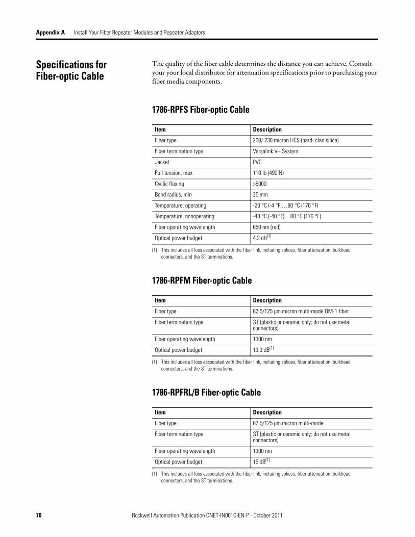
Appendix A Install Your Fiber Repeater Modules and Repeater Adapters
Specifications forFiber-optic Cable
The quality of the fiber cable determines the distance you can achieve. Consult your your local distributor for attenuation specifications prior to purchasing your fiber media components.
1786-RPFS Fiber-optic Cable
1786-RPFM Fiber-optic Cable
1786-RPFRL/B Fiber-optic Cable
Item Description
Fiber type 200/ 230 micron HCS (hard- clad silica)
Fiber termination type Versalink V– System
Jacket PVC
Pull tension, max 110 lb (490 N)
Cyclic flexing >5000
Bend radius, min 25 mm
Temperature, operating -20 °C (-4 °F)…80 °C (176 °F)
Temperature, nonoperating -40 °C (-40 °F)…80 °C (176 °F)
Fiber operating wavelength 650 nm (red)
Optical power budget 4.2 dB(1)
(1) This includes all loss associated with the fiber link, including splices, fiber attenuation, bulkhead connectors, and the ST terminations.
Item Description
Fiber type 62.5/125 µm micron multi-mode OM-1 fiber
Fiber termination type ST (plastic or ceramic only; do not use metal connectors)
Fiber operating wavelength 1300 nm
Optical power budget 13.3 dB(1)
(1) This includes all loss associated with the fiber link, including splices, fiber attenuation, bulkhead connectors, and the ST terminations.
Item Description
Fiber type 62.5/125 µm micron multi-mode
Fiber termination type ST (plastic or ceramic only; do not use metal connectors)
Fiber operating wavelength 1300 nm
Optical power budget 15 dB(1)
(1) This includes all loss associated with the fiber link, including splices, fiber attenuation, bulkhead connectors, and the ST terminations.
70 Rockwell Automation Publication CNET-IN001C-EN-P - October 2011
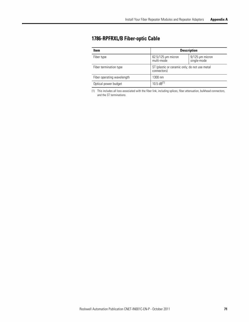
Install Your Fiber Repeater Modules and Repeater Adapters Appendix A
1786-RPFRXL/B Fiber-optic Cable
Item Description
Fiber type 62.5/125 µm micronmulti-mode
9/125 µm micronsingle-mode
Fiber termination type ST (plastic or ceramic only; do not use metal connectors)
Fiber operating wavelength 1300 nm
Optical power budget 10.5 dB(1)
(1) This includes all loss associated with the fiber link, including splices, fiber attenuation, bulkhead connectors, and the ST terminations.
Rockwell Automation Publication CNET-IN001C-EN-P - October 2011 71

Appendix A Install Your Fiber Repeater Modules and Repeater Adapters
Notes:
72 Rockwell Automation Publication CNET-IN001C-EN-P - October 2011

Appendix B
Status Indicators
The 1786-RPA/B repeater adapter has a pair of status indicators:• One status indicator for the condition of the coax connection• One status indicator for the accumulative indications of fiber channels
The status indicators on the repeater adapter module can be interpreted aloneor together.
The following three tables list different combinations of status indicators and their interpretations.
Status Indicators Page
Power-up and fault conditions Table 10 on page 74
Repeater adapter module only Table 11 on page 74
Repeater modules only Table 12 on page 75
IMPORTANT The following are the only valid indicator combinations. Other combinations are not valid. For example, the combination of therepeater adapter module’s solid green status indicator and therepeater module’s solid red status indicator is not valid and probably indicates a defective module.
COM
COM
REPEATERADAPTER
REPEATERMODULES
24V+ +
Repeater Adapter
Repeater Modules
Rockwell Automation Publication CNET-IN001C-EN-P - October 2011 73

Appendix B Status Indicators
Table 10 - Power-up and Fault Conditions
Indicator Status Description
Repeater adapter Alternating red/green Repeater adapter module is being powered up or reset. Do nothing. The repeater adapter module is operating properly.
Solid red A jabber condition has occurred. Another node or repeater on the network is transmitting constantly. Check the network and components for proper operation.
Off Repeater adapter module is not powered up or has failed. Check the power input to the repeater adapter module for correct voltage and polarity.
Table 11 - Repeater Adapter Module Status Indicator
Indicator Status Description
Repeater adapter Solid green Error-free data is being recovered at the coax port of the repeater adapter module. Do nothing. This is the normal operating mode.
Flashing green/off Data with errors is occasionally being recovered at the coax port of the repeater adapter module.This situation normally corrects itself. If the situation persists, check the following:• All BNC connector pins are
seated properly.• All taps are Rockwell
Automation taps.• All terminators are 75 Ω and are
installed at both ends of all segments.
• Coax cable has not been grounded.
Flashing red/off Either no data is being received at the coax port of the repeater adapter module, or data with a large number of errors is being received at the coax port of the repeater adapter module.Check the following components:• Broken cables• Broken taps• Missing segment terminators
74 Rockwell Automation Publication CNET-IN001C-EN-P - October 2011
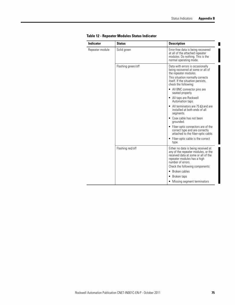
Status Indicators Appendix B
Table 12 - Repeater Modules Status Indicator
Indicator Status Description
Repeater module Solid green Error-free data is being recovered at all of the attached repeater modules. Do nothing. This is the normal operating mode.
Flashing green/off Data with errors is occasionally being recovered at some or all of the repeater modules.This situation normally corrects itself. If the situation persists, check the following:• All BNC connector pins are
seated properly.• All taps are Rockwell
Automation taps.• All terminators are 75 Ω and are
installed at both ends of all segments.
• Coax cable has not been grounded.
• Fiber-optic connectors are of the correct type and are correctly attached to the fiber-optic cable.
• Fiber-optic cable is the correct type.
Flashing red/off Either no data is being received at any of the repeater modules, or the received data at some or all of the repeater modules has a high number of errors.Check the following components:• Broken cables• Broken taps• Missing segment terminators
Rockwell Automation Publication CNET-IN001C-EN-P - October 2011 75

Appendix B Status Indicators
1786-RPFS and 1786-RPFM Status Indicators
Use the channel 1 or 2 status indicators to check module status.
Table 13 - Short- or Medium-distance Fiber Repeater Modules
Indicator Status Description
Either channel 1 or channel 2
Off Repeater not connected to power supply.
Green Channel is operating normally.
Flashing green No activity on the channel.
Channel 1 Status Indicator
Channel 2 Status Indicator30041
76 Rockwell Automation Publication CNET-IN001C-EN-P - October 2011
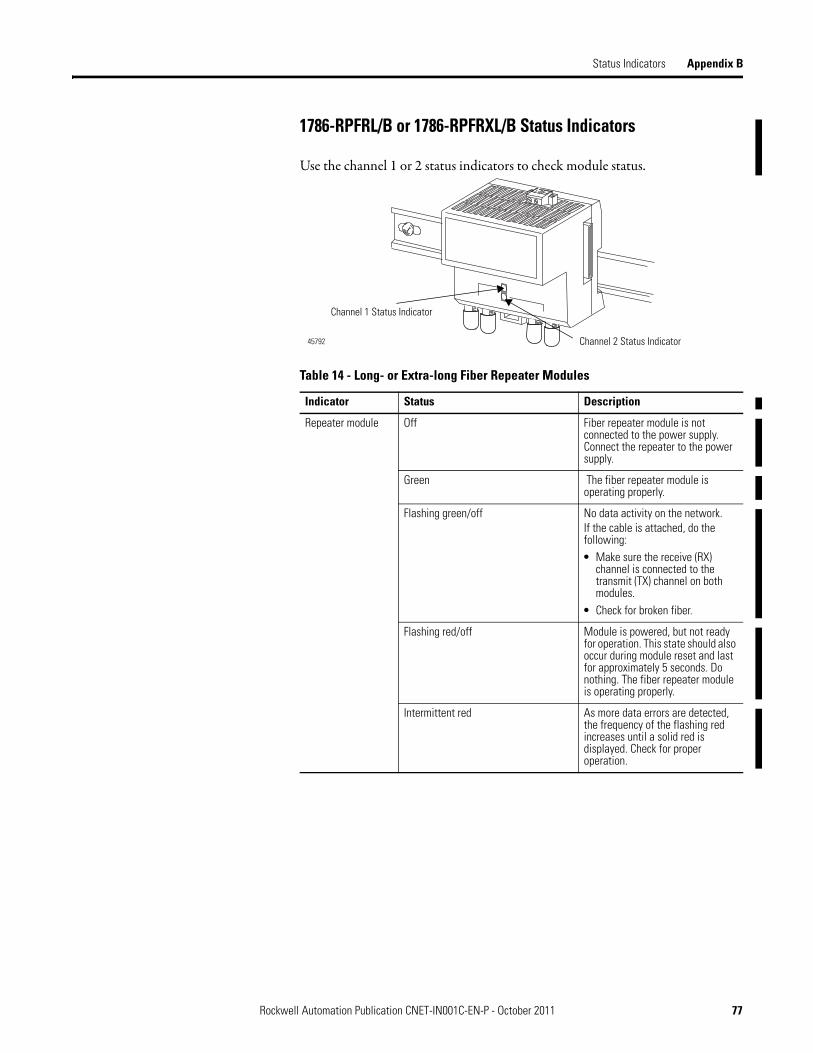
Status Indicators Appendix B
1786-RPFRL/B or 1786-RPFRXL/B Status Indicators
Use the channel 1 or 2 status indicators to check module status.
Table 14 - Long- or Extra-long Fiber Repeater Modules
Indicator Status Description
Repeater module Off Fiber repeater module is not connected to the power supply. Connect the repeater to the power supply.
Green The fiber repeater module is operating properly.
Flashing green/off No data activity on the network.If the cable is attached, do the following:• Make sure the receive (RX)
channel is connected to the transmit (TX) channel on both modules.
• Check for broken fiber.
Flashing red/off Module is powered, but not ready for operation. This state should also occur during module reset and last for approximately 5 seconds. Do nothing. The fiber repeater module is operating properly.
Intermittent red As more data errors are detected, the frequency of the flashing red increases until a solid red is displayed. Check for proper operation.
Channel 1 Status Indicator
Channel 2 Status Indicator45792
Rockwell Automation Publication CNET-IN001C-EN-P - October 2011 77

Appendix B Status Indicators
1786-RPFRL/B or 1786-RPFRXL/B Relay Contact Connectors
The 1786-RPFRL/B and 1786-RPFRXL/B fiber repeater modules contain a single electromechanical relay for communication and system status. The relay provides an efficient way to locate a faulted module.
Repeater module Red Excessive receive signal distortion.Review these items:• Be certain that you are using the
correct fiber type for your module.
• Check fiber length and attenuation to make sure that it is within specification.
• Replace the downstream1786-RPFRL module on the channel that has the intermittently flashing redstatus indicator.
• Be certain that your total network length is not out of specification.
• Be certain that SMAX is correctly defined in the RSNetWorx for ControlNet software.
Table 15 - Relay Contact Connector Diagnostics
Indicator Status Description
Channel 1 or channel 2
Not solid green The relay contact is open.No receive data is present at one or both fiber-optic ports for more than 1300 ms (that means if either of the channel status indicators are not solid green, the fault relay opens.)The repeater is not connected to the power supply.
Off The relay contact is closed.Neither of the above conditionsis met.
Table 14 - Long- or Extra-long Fiber Repeater Modules
Indicator Status Description
Relay Contact Connector
31531-M
78 Rockwell Automation Publication CNET-IN001C-EN-P - October 2011

Glossary
The following terms and abbreviations are used throughout this manual. For definitions of terms not listed here, refer to the Allen-Bradley Industrial Automation Glossary, publication AG-7.1.
APD (avalanche photo diodes) Converts light to current in fiber receivers.
attenuation (loss) Ratio of input optical power to output optical power for a length of fiber optic cable in dB/km.
bandwidth Pulse broadening caused by multi-mode dispersion and chromatic dispersion within the cable.
baseband Information is transmitted through fiber by modulation of the optical power.
BER (bit error rate) Primary method of describing the data error rate. An acceptable error rate is1 × 10-9 bit errors (or 1 error in 1000 Mbits transmitted).
bend radius Maximum amount the cable can be bent and still function up to specification.
buffer Material surrounding the fiber (core, cladding, coating) that protects the fiber from physical damage. Tight buffers are in direct contact with the fiber.Loose-tube buffers provide a free environment for the fiber to float.
cladding Layer of material surrounding the core of a fiber.
coating Protective plastic material surrounding the cladding.
core Central cylinder of a fiber that is made of plastic or glass.
dB Unit of measure for loss or gain of power described as 10 × log (pout/pin).
dBM Power level referenced to 1 mw described as 10 × log (poptical/1 mw).
ferrite A passive electric component that is used to suppress high frequency noise in electronic circuits.
graded index Fiber system where light travels in wave-like tracks to increase cable bandwidth.
insertion loss Loss in dB caused by the disruption of light when an object is inserted in the light path (a connector, bulkhead, splice, or cable).
laser diode Converts electric energy into light energy to be coupled onto fiber media.
LED (light emitting diode) Converts electric energy into light.
Rockwell Automation Publication CNET-IN001C-EN-P - October 2011 79

Glossary
local area network Family of computer networks, industrial control networks, and office networks used in short-distance, multi-user environments.
loss see attenuation (loss)
multi-mode Class of fibers where the light travels in multiple paths down the fiber core.
numerical aperture (NA) In a lens or fiber, the sine of half the maximum angle of acceptance α. NA = sin α = √(n12 - n22) where n1= core refractive index and n2=cladding refractive index.
network update time (NUT) Time necessary to complete the scheduled bandwidth, unscheduled bandwidth, and network maintenance in the network interval.
OTDR (optical timedomain reflectometer)
Tool for characterizing fiber attenuation, uniformity, splice loss, breaks, or length.
photo diode see pin diode
pin diode Used as a receiving device in fiber optic systems to detect the presence of light and convert that light energy into electrical energy.
plastic clad silica fiber Step-index fiber made from silica core and a plastic cladding.
plastic fiber fiber consisting only of plastic with usually higher attenuation than glass.
receiver Produces logic levels in a fiber optic system by using photo diodes, resistors, amplifiers, and level shift circuits.
refractive index Ratio of the speed of light in a vacuum to the speed of light in the material.
responsivity Ratio of output current/voltage to the optical input power.
return loss Logarithmic ratio of power into a device to the power reflected back due to mismatches in a system. Return Loss = 10 × log (Pin/Pback).
scheduled maximum node address(SMAX)
Highest scheduled node address on the ControlNet network.
sensitivity Minimum optical power amplitude at the input of a receiver in order to achieve a predefined BER.
single-mode Class of fibers in which light travels in a single path down the fiber core.
speed of light Phase velocity of an optical wave in a vacuum.
80 Rockwell Automation Publication CNET-IN001C-EN-P - October 2011

Glossary
splice Connection in the fiber designed to increase the length of the fiber.
step index Fibers with a refractive-index profile form in a rectangle.
tap Couples a fraction of optical power from a fiber to a receiver.
unscheduled maximum node address(UMAX)
The highest unscheduled node address on the ControlNet network.
Rockwell Automation Publication CNET-IN001C-EN-P - October 2011 81

Glossary
Notes:
82 Rockwell Automation Publication CNET-IN001C-EN-P - October 2011

Index
Numerics1786-RPA/B module
status indicators 73wiring 68
1786-RPFM modulecable specifications 70status indicators 76
1786-RPFRL/B modulecable specifications 70description 34relay contact connector 78status indicators 77
1786-RPFRXL/B modulecable specifications 71description 35relay contact connector 78status indicators 77
1786-RPFS modulecable specifications 70connection 65description 34status indicators 76
Aattenuation
levels 35medium distance 37, 38
records 56
BBNC
cable connectors 12
Ccable
200 micron HSC 65connectors 12estimate lengths 33specifications
1786-RPFM module 701786-RPFRL/B module 701786-RPFRXL/B module 711786-RPFS module 70
terminate 67cable type
duplex 32multi-fiber backbone 32simplex 31
coaxconstraints 30
combinationinstallation 20
conduitinstallation 46
connection1786-RPFS module 65fiber repeater module 66poor 57
considerationstopology 29
constraintscoax 30fiber 31
ControlNet network cable systemconnectors 12node 12tap 15
current drawrepeater modules 14
Ddelay
propagation 38values 38
ductinstallation 46
duplexcable type 32
Eelectrical isolation 12entry into hazardous areas 12estimate
cable lengths 33
Fferrite
definition 62power supply 62relay contact connector 63
fibercable cross-section 13cable guidelines 44cable specifications 70connectors 12constraints 31handling guidelines 44longer distances 12media 11media components 12media specialist 43mount module 60repeater module
connection 66
Gguidelines
handling cable 44installation 59
Rockwell Automation Publication CNET-IN001C-EN-P - October 2011 83
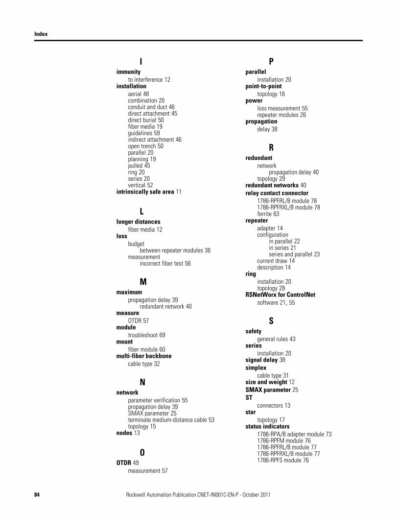
Index
Iimmunity
to interference 12installation
aerial 48combination 20conduit and duct 46direct attachment 45direct burial 50fiber media 19guidelines 59indirect attachment 46open trench 50parallel 20planning 19pulled 45ring 20series 20vertical 52
intrinsically safe area 11
Llonger distances
fiber media 12loss
budgetbetween repeater modules 36
measurementincorrect fiber test 56
Mmaximum
propagation delay 39redundant network 40
measureOTDR 57
moduletroubleshoot 69
mountfiber module 60
multi-fiber backbonecable type 32
Nnetwork
parameter verification 55propagation delay 39SMAX parameter 25terminate medium-distance cable 53topology 15
nodes 13
OOTDR 49
measurement 57
Pparallel
installation 20point-to-point
topology 16power
loss measurement 55repeater modules 26
propagationdelay 38
Rredundant
networkpropagation delay 40
topology 29redundant networks 40relay contact connector
1786-RPFRL/B module 781786-RPFRXL/B module 78ferrite 63
repeateradapter 14configuration
in parallel 22in series 21series and parallel 23
current draw 14description 14
ringinstallation 20topology 28
RSNetWorx for ControlNetsoftware 21, 55
Ssafety
general rules 43series
installation 20signal delay 38simplex
cable type 31size and weight 12SMAX parameter 25ST
connectors 13star
topology 17status indicators
1786-RPA/B adapter module 731786-RPFM module 761786-RPFRL/B module 771786-RPFRXL/B module 771786-RPFS module 76
84 Rockwell Automation Publication CNET-IN001C-EN-P - October 2011

Index
Ttap description 15terminate
cable 26, 53, 67terminating resistor
description 15test
media connections and segments 26topology 15
considerations 29point-to-point 16redundant 29ring 28star 17
troubleshootmodule 69, 73
Vverify
network 26V-pin
connector 13
Wwiring
1786-RPA/B module 68worst case
signal delay 38
Rockwell Automation Publication CNET-IN001C-EN-P - October 2011 85

Index
Notes:
86 Rockwell Automation Publication CNET-IN001C-EN-P - October 2011


Rockwell Otomasyon Ticaret A.Ş., Kar Plaza İş Merkezi E Blok Kat:6 34752 İçerenköy, İstanbul, Tel: +90 (216) 5698400
Publication CNET-IN001C-EN-P - October 2011 88Supersedes Publication CNET-IN001B-EN-P - July 2004 Copyright © 2011 Rockwell Automation, Inc. All rights reserved. Printed in the U.S.A.
Rockwell Automation Support
Rockwell Automation provides technical information on the Web to assist you in using its products. At http://www.rockwellautomation.com/support/, you can find technical manuals, a knowledge base of FAQs, technical and application notes, sample code and links to software service packs, and a MySupport feature that you can customize to make thebest use of these tools.
For an additional level of technical phone support for installation, configuration, and troubleshooting, we offer TechConnect support programs. For more information, contact your local distributor or Rockwell Automation representative, or visit http://www.rockwellautomation.com/support/.
Installation Assistance
If you experience a problem within the first 24 hours of installation, review the information that is contained in this manual.You can contact Customer Support for initial help in getting your product up and running.
New Product Satisfaction Return
Rockwell Automation tests all of its products to ensure that they are fully operational when shipped from the manufacturing facility. However, if your product is not functioning and needs to be returned, follow these procedures.
Documentation Feedback
Your comments will help us serve your documentation needs better. If you have any suggestions on how to improve this document, complete this form, publication RA-DU002, available at http://www.rockwellautomation.com/literature/.
United States or Canada 1.440.646.3434
Outside United States or Canada
Use the Worldwide Locator at http://www.rockwellautomation.com/support/americas/phone_en.html, or contact your local Rockwell Automation representative.
United States Contact your distributor. You must provide a Customer Support case number (call the phone number above to obtain one) to your distributor to complete the return process.
Outside United States Please contact your local Rockwell Automation representative for the return procedure.
![[XLS]dallascityhall.comdallascityhall.com/departments/sustainabledevelopment... · Web view4100 5000 17000 32000 32000 33000 2975 26285 4000 2800 8500 3700 3500 850 5000 1786 1786](https://img.pdfslide.us/doc/110x75/5acaca377f8b9a42358e23ca/xls-view4100-5000-17000-32000-32000-33000-2975-26285-4000-2800-8500-3700-3500.jpg)