Embed Size (px)
Citation preview

ControlLogix Analog I/O ModulesCatalog Numbers 1756-IF16, 1756-IF6CIS, 1756-IF6I, 1756-IF8, 1756-IR6I, 1756-IT6I, 1756-IT6I2, 1756-OF4, 1756-OF6CI, 1756-OF6VI, 1756-OF8
User Manual
Important User Information
Read this document and the documents listed in the additional resources section about installation, configuration, and operation of this equipment before you install, configure, operate, or maintain this product. Users are required to familiarize themselves with installation and wiring instructions in addition to requirements of all applicable codes, laws, and standards.
Activities including installation, adjustments, putting into service, use, assembly, disassembly, and maintenance are required to be carried out by suitably trained personnel in accordance with applicable code of practice.
If this equipment is used in a manner not specified by the manufacturer, the protection provided by the equipment may be impaired.
In no event will Rockwell Automation, Inc. be responsible or liable for indirect or consequential damages resulting from the use or application of this equipment.
The examples and diagrams in this manual are included solely for illustrative purposes. Because of the many variables and requirements associated with any particular installation, Rockwell Automation, Inc. cannot assume responsibility or liability for actual use based on the examples and diagrams.
No patent liability is assumed by Rockwell Automation, Inc. with respect to use of information, circuits, equipment, or software described in this manual.
Reproduction of the contents of this manual, in whole or in part, without written permission of Rockwell Automation, Inc., is prohibited.
Throughout this manual, when necessary, we use notes to make you aware of safety considerations.
Labels may also be on or inside the equipment to provide specific precautions.
Allen-Bradley, Rockwell Automation, Rockwell Software, RSLogix 5000, Logix5000, RSNetWorx, RSLinx, PowerFlex, DeviceNet, EtherNet/IP, Data Highway Plus-Remote I/O, and TechConnect are trademarks of Rockwell Automation, Inc.
Trademarks not belonging to Rockwell Automation are property of their respective companies.
WARNING: Identifies information about practices or circumstances that can cause an explosion in a hazardous environment, which may lead to personal injury or death, property damage, or economic loss.
ATTENTION: Identifies information about practices or circumstances that can lead to personal injury or death, property damage, or economic loss. Attentions help you identify a hazard, avoid a hazard, and recognize the consequence.
IMPORTANT Identifies information that is critical for successful application and understanding of the product.
SHOCK HAZARD: Labels may be on or inside the equipment, for example, a drive or motor, to alert people that dangerous voltage may be present.
BURN HAZARD: Labels may be on or inside the equipment, for example, a drive or motor, to alert people that surfaces may reach dangerous temperatures.
ARC FLASH HAZARD: Labels may be on or inside the equipment, for example, a motor control center, to alert people to potential Arc Flash. Arc Flash will cause severe injury or death. Wear proper Personal Protective Equipment (PPE). Follow ALL Regulatory requirements for safe work practices and for Personal Protective Equipment (PPE).
Summary of Changes
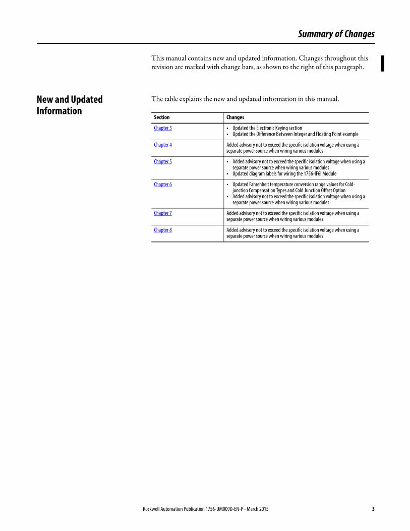
This manual contains new and updated information. Changes throughout this revision are marked with change bars, as shown to the right of this paragraph.
New and Updated Information
The table explains the new and updated information in this manual.
Section Changes
Chapter 3 • Updated the Electronic Keying section• Updated the Difference Between Integer and Floating Point example
Chapter 4 Added advisory not to exceed the specific isolation voltage when using a separate power source when wiring various modules
Chapter 5 • Added advisory not to exceed the specific isolation voltage when using a separate power source when wiring various modules
• Updated diagram labels for wiring the 1756-IF6I Module
Chapter 6 • Updated Fahrenheit temperature conversion range values for Cold-junction Compensation Types and Cold Junction Offset Option
• Added advisory not to exceed the specific isolation voltage when using a separate power source when wiring various modules
Chapter 7 Added advisory not to exceed the specific isolation voltage when using a separate power source when wiring various modules
Chapter 8 Added advisory not to exceed the specific isolation voltage when using a separate power source when wiring various modules
Rockwell Automation Publication 1756-UM009D-EN-P - March 2015 3

Summary of Changes
Notes:
4 Rockwell Automation Publication 1756-UM009D-EN-P - March 2015
Table of Contents
Preface Introduction. . . . . . . . . . . . . . . . . . . . . . . . . . . . . . . . . . . . . . . . . . . . . . . . . . . . . 13Who Should Use This Manual . . . . . . . . . . . . . . . . . . . . . . . . . . . . . . . . . . . . 13For More Information. . . . . . . . . . . . . . . . . . . . . . . . . . . . . . . . . . . . . . . . . . . . 13
Chapter 1What Are ControlLogix Analog I/O Modules?
Introduction. . . . . . . . . . . . . . . . . . . . . . . . . . . . . . . . . . . . . . . . . . . . . . . . . . . . . 15I/O Module in the ControlLogix System. . . . . . . . . . . . . . . . . . . . . . . . . . . 16Module Identification and Status Information. . . . . . . . . . . . . . . . . . . . . . 17Preventing Electrostatic Discharge. . . . . . . . . . . . . . . . . . . . . . . . . . . . . . . . . 18
Chapter 2Analog I/O Operation in theControlLogix System
Introduction. . . . . . . . . . . . . . . . . . . . . . . . . . . . . . . . . . . . . . . . . . . . . . . . . . . . . 19Ownership . . . . . . . . . . . . . . . . . . . . . . . . . . . . . . . . . . . . . . . . . . . . . . . . . . . . . . 19Using RSNetWorx and RSLogix 5000 Software . . . . . . . . . . . . . . . . . . . . 20Direct Connections . . . . . . . . . . . . . . . . . . . . . . . . . . . . . . . . . . . . . . . . . . . . . . 21Input Module Operation . . . . . . . . . . . . . . . . . . . . . . . . . . . . . . . . . . . . . . . . . 22Input Modules in a Local Chassis . . . . . . . . . . . . . . . . . . . . . . . . . . . . . . . . . . 22
Real Time Sample (RTS). . . . . . . . . . . . . . . . . . . . . . . . . . . . . . . . . . . . . . 22Requested Packet Interval (RPI) . . . . . . . . . . . . . . . . . . . . . . . . . . . . . . . 23Triggering Event Tasks . . . . . . . . . . . . . . . . . . . . . . . . . . . . . . . . . . . . . . . 24
Input Modules in a Remote Chassis. . . . . . . . . . . . . . . . . . . . . . . . . . . . . . . . 25Remote Input Modules Connected Via the ControlNet Network . . . . . . . . . . . . . . . . . . . . . . . . . . . . . . . . . . . . . . . . . 25Remote Input Modules Connected Via the EtherNet/IP Network . . . . . . . . . . . . . . . . . . . . . . . . . . . . . . . . . . . . . . . . 26
Output Module Operation . . . . . . . . . . . . . . . . . . . . . . . . . . . . . . . . . . . . . . . 27Output Modules in a Local Chassis . . . . . . . . . . . . . . . . . . . . . . . . . . . . . . . . 27Output Modules in a Remote Chassis. . . . . . . . . . . . . . . . . . . . . . . . . . . . . . 28
Remote Output Modules Connected Via the ControlNet Network . . . . . . . . . . . . . . . . . . . . . . . . . . . . . . . . . . . . . . . . . 28Remote Output Modules Connected Via the EtherNet/IP Network . . . . . . . . . . . . . . . . . . . . . . . . . . . . . . . . . . . . . . . . 29
Listen-only Mode . . . . . . . . . . . . . . . . . . . . . . . . . . . . . . . . . . . . . . . . . . . . . . . . 30Multiple Owners of Input Modules . . . . . . . . . . . . . . . . . . . . . . . . . . . . . . . . 31Configuration Changes in an Input Module with Multiple Owners . . . . . . . . . . . . . . . . . . . . . . . . . . . . . . . . . . . . . . . . . . . . . . . . . 32
Chapter 3ControlLogix Analog I/O Module Features
Introduction. . . . . . . . . . . . . . . . . . . . . . . . . . . . . . . . . . . . . . . . . . . . . . . . . . . . . 33Common Analog I/O Features . . . . . . . . . . . . . . . . . . . . . . . . . . . . . . . . . . . . 33
Removal and Insertion Under Power (RIUP) . . . . . . . . . . . . . . . . . . . 34Module Fault Reporting . . . . . . . . . . . . . . . . . . . . . . . . . . . . . . . . . . . . . . 34Configurable Software . . . . . . . . . . . . . . . . . . . . . . . . . . . . . . . . . . . . . . . . 34
Electronic Keying . . . . . . . . . . . . . . . . . . . . . . . . . . . . . . . . . . . . . . . . . . . . . . . . 34
Rockwell Automation Publication 1756-UM009D-EN-P - March 2015 5
Table of Contents
More Information . . . . . . . . . . . . . . . . . . . . . . . . . . . . . . . . . . . . . . . . . . . . 35Access to System Clock for Timestamp Functions . . . . . . . . . . . . . . . 36Rolling Timestamp . . . . . . . . . . . . . . . . . . . . . . . . . . . . . . . . . . . . . . . . . . . 36Producer/Consumer Model . . . . . . . . . . . . . . . . . . . . . . . . . . . . . . . . . . . 36Status Indicator Information . . . . . . . . . . . . . . . . . . . . . . . . . . . . . . . . . . 37Full Class I Division 2 Compliance. . . . . . . . . . . . . . . . . . . . . . . . . . . . . 37Agency Certification . . . . . . . . . . . . . . . . . . . . . . . . . . . . . . . . . . . . . . . . . . 37Field Calibration . . . . . . . . . . . . . . . . . . . . . . . . . . . . . . . . . . . . . . . . . . . . . 37Sensor Offset . . . . . . . . . . . . . . . . . . . . . . . . . . . . . . . . . . . . . . . . . . . . . . . . . 38Latching of Alarms . . . . . . . . . . . . . . . . . . . . . . . . . . . . . . . . . . . . . . . . . . . 38Data Format . . . . . . . . . . . . . . . . . . . . . . . . . . . . . . . . . . . . . . . . . . . . . . . . . 38Module Inhibiting . . . . . . . . . . . . . . . . . . . . . . . . . . . . . . . . . . . . . . . . . . . . 39
Relationship Between Module Resolution, Scaling, and Data Format . . . . . . . . . . . . . . . . . . . . . . . . . . . . . . . . . . . . . . . . . . . . . . . . . 40
Module Resolution . . . . . . . . . . . . . . . . . . . . . . . . . . . . . . . . . . . . . . . . . . . 40Scaling . . . . . . . . . . . . . . . . . . . . . . . . . . . . . . . . . . . . . . . . . . . . . . . . . . . . . . . 42Data Format as Related to Resolution and Scaling . . . . . . . . . . . . . . . 43
Chapter 4Non-isolated Analog Voltage/Current Input Modules (1756-IF16, 1756-IF8)
Introduction . . . . . . . . . . . . . . . . . . . . . . . . . . . . . . . . . . . . . . . . . . . . . . . . . . . . . 47Choose a Wiring Method . . . . . . . . . . . . . . . . . . . . . . . . . . . . . . . . . . . . . . . . . 48
Single-ended Wiring Method . . . . . . . . . . . . . . . . . . . . . . . . . . . . . . . . . . 48Differential Wiring Method . . . . . . . . . . . . . . . . . . . . . . . . . . . . . . . . . . . 49High-speed Mode Differential Wiring Method. . . . . . . . . . . . . . . . . . 49
Choose a Data Format . . . . . . . . . . . . . . . . . . . . . . . . . . . . . . . . . . . . . . . . . . . . 50Features Specific to Non-Isolated Analog Input Modules . . . . . . . . . . . . 51
Multiple Input Ranges . . . . . . . . . . . . . . . . . . . . . . . . . . . . . . . . . . . . . . . . 51Module Filter . . . . . . . . . . . . . . . . . . . . . . . . . . . . . . . . . . . . . . . . . . . . . . . . 52Real Time Sampling . . . . . . . . . . . . . . . . . . . . . . . . . . . . . . . . . . . . . . . . . . 53Underrange/Overrange Detection . . . . . . . . . . . . . . . . . . . . . . . . . . . . . 53Digital Filter . . . . . . . . . . . . . . . . . . . . . . . . . . . . . . . . . . . . . . . . . . . . . . . . . 54Process Alarms . . . . . . . . . . . . . . . . . . . . . . . . . . . . . . . . . . . . . . . . . . . . . . . 54Rate Alarm. . . . . . . . . . . . . . . . . . . . . . . . . . . . . . . . . . . . . . . . . . . . . . . . . . . 55Wire Off Detection . . . . . . . . . . . . . . . . . . . . . . . . . . . . . . . . . . . . . . . . . . . 56
Use Module Block and Input Circuit Diagrams . . . . . . . . . . . . . . . . . . . . . 58Field-side Circuit Diagrams. . . . . . . . . . . . . . . . . . . . . . . . . . . . . . . . . . . . 59
Wire the 1756-IF16 Module . . . . . . . . . . . . . . . . . . . . . . . . . . . . . . . . . . . . . . 61Wire the 1756-IF8 Module . . . . . . . . . . . . . . . . . . . . . . . . . . . . . . . . . . . . . . . 651756-IF16 Module Fault and Status Reporting . . . . . . . . . . . . . . . . . . . . . 691756-IF16 Fault Reporting in Floating Point Mode . . . . . . . . . . . . . . . . . 70
1756-IF16 Module Fault Word Bits – Floating Point Mode. . . . . . 711756-IF16 Channel Fault Word Bits – Floating Point Mode . . . . . 711756-IF16 Channel Status Word Bits – Floating Point Mode . . . . 71
1756-IF16 Fault Reporting in Integer Mode . . . . . . . . . . . . . . . . . . . . . . . . 721756-IF16 Module Fault Word Bits – Integer Mode. . . . . . . . . . . . . 741756-IF16 Channel Fault Word Bits – Integer Mode . . . . . . . . . . . . 741756-IF16 Channel Status Word Bits – Integer Mode . . . . . . . . . . . 75
6 Rockwell Automation Publication 1756-UM009D-EN-P - March 2015
Table of Contents
1756-IF8 Module Fault and Status Reporting . . . . . . . . . . . . . . . . . . . . . . 761756-IF8 Fault Reporting in Floating Point Mode . . . . . . . . . . . . . . . . . . 77
1756-IF8 Module Fault Word Bits – Floating Point Mode. . . . . . . 781756-IF8 Channel Fault Word Bits – Floating Point Mode . . . . . . 781756-IF8 Channel Status Word Bits – Floating Point Mode . . . . . 78
1756-IF8 Fault Reporting in Integer Mode . . . . . . . . . . . . . . . . . . . . . . . . . 801756-IF8 Module Fault Word Bits – Integer Mode . . . . . . . . . . . . . 811756-IF8 Channel Fault Word Bits – Integer Mode. . . . . . . . . . . . . 811756-IF8 Channel Status Word Bits – Integer Mode . . . . . . . . . . . . 82
Chapter 5Sourcing Current Loop Input Module (1756-IF6CIS) and Isolated Analog Voltage/Current Input Modul e (1756-IF6I)
Introduction. . . . . . . . . . . . . . . . . . . . . . . . . . . . . . . . . . . . . . . . . . . . . . . . . . . . . 83Use the Isolated Power Source on the 1756-IF6CIS . . . . . . . . . . . . . . . . . 84
Power Calculations with the 1756-IF6CIS Module . . . . . . . . . . . . . 84Other Devices in the Wiring Loop . . . . . . . . . . . . . . . . . . . . . . . . . . . . . 84
Choose a Data Format. . . . . . . . . . . . . . . . . . . . . . . . . . . . . . . . . . . . . . . . . . . . 85Features Specific to the 1756-IF6I and 1756-IF6CIS Modules . . . . . . . 85
Multiple Input Ranges . . . . . . . . . . . . . . . . . . . . . . . . . . . . . . . . . . . . . . . . 86Notch Filter . . . . . . . . . . . . . . . . . . . . . . . . . . . . . . . . . . . . . . . . . . . . . . . . . 87Real Time Sampling . . . . . . . . . . . . . . . . . . . . . . . . . . . . . . . . . . . . . . . . . . 87Underrange/Overrange Detection . . . . . . . . . . . . . . . . . . . . . . . . . . . . . 88Digital Filter . . . . . . . . . . . . . . . . . . . . . . . . . . . . . . . . . . . . . . . . . . . . . . . . . 89Process Alarms . . . . . . . . . . . . . . . . . . . . . . . . . . . . . . . . . . . . . . . . . . . . . . . 89Rate Alarm . . . . . . . . . . . . . . . . . . . . . . . . . . . . . . . . . . . . . . . . . . . . . . . . . . 90Wire Off Detection . . . . . . . . . . . . . . . . . . . . . . . . . . . . . . . . . . . . . . . . . . 92
Use Module Block and Input Circuit Diagrams. . . . . . . . . . . . . . . . . . . . . 93Field-side Circuit Diagrams . . . . . . . . . . . . . . . . . . . . . . . . . . . . . . . . . . . 94
Wire the 1756-IF6CIS Module . . . . . . . . . . . . . . . . . . . . . . . . . . . . . . . . . . . 95 Wire the 1756-IF6I Module . . . . . . . . . . . . . . . . . . . . . . . . . . . . . . . . . . . . . . 981756-IF6CIS or 1756-IF6I Module Fault and Status Reporting . . . . . 100Fault Reporting in Floating Point Mode . . . . . . . . . . . . . . . . . . . . . . . . . . 101
Module Fault Word Bits – Floating Point Mode . . . . . . . . . . . . . . . 102Channel Fault Word Bits – Floating Point Mode . . . . . . . . . . . . . . 102Channel Status Word Bits – Floating Point Mode . . . . . . . . . . . . . 103
Fault Reporting in Integer Mode . . . . . . . . . . . . . . . . . . . . . . . . . . . . . . . . . 104Module Fault Word Bits – Integer Mode . . . . . . . . . . . . . . . . . . . . . . 104Channel Fault Word Bits – Integer Mode . . . . . . . . . . . . . . . . . . . . . 105Channel Status Word Bits – Integer Mode . . . . . . . . . . . . . . . . . . . . 105
Chapter 6Temperature-measuring Analog Modules (1756-IR6I, 1756-IT6I, and 1756-IT6I2)
Introduction. . . . . . . . . . . . . . . . . . . . . . . . . . . . . . . . . . . . . . . . . . . . . . . . . . . . 107Choose a Data Format. . . . . . . . . . . . . . . . . . . . . . . . . . . . . . . . . . . . . . . . . . . 108Temperature-measuring Module Features . . . . . . . . . . . . . . . . . . . . . . . . . 109
Multiple Input Ranges . . . . . . . . . . . . . . . . . . . . . . . . . . . . . . . . . . . . . . . 109Notch Filter . . . . . . . . . . . . . . . . . . . . . . . . . . . . . . . . . . . . . . . . . . . . . . . . 110Real Time Sampling . . . . . . . . . . . . . . . . . . . . . . . . . . . . . . . . . . . . . . . . . 111
Rockwell Automation Publication 1756-UM009D-EN-P - March 2015 7
Table of Contents
Underrange/Overrange Detection . . . . . . . . . . . . . . . . . . . . . . . . . . . . 111Digital Filter . . . . . . . . . . . . . . . . . . . . . . . . . . . . . . . . . . . . . . . . . . . . . . . . 112Process Alarms . . . . . . . . . . . . . . . . . . . . . . . . . . . . . . . . . . . . . . . . . . . . . . 112Rate Alarm. . . . . . . . . . . . . . . . . . . . . . . . . . . . . . . . . . . . . . . . . . . . . . . . . . 11410 Ohm Offset . . . . . . . . . . . . . . . . . . . . . . . . . . . . . . . . . . . . . . . . . . . . . . 114Wire Off Detection . . . . . . . . . . . . . . . . . . . . . . . . . . . . . . . . . . . . . . . . . . 115Sensor Type . . . . . . . . . . . . . . . . . . . . . . . . . . . . . . . . . . . . . . . . . . . . . . . . . 116Temperature Units . . . . . . . . . . . . . . . . . . . . . . . . . . . . . . . . . . . . . . . . . . 117Input Signal to User Count Conversion . . . . . . . . . . . . . . . . . . . . . . . 117Wire Length Calculations . . . . . . . . . . . . . . . . . . . . . . . . . . . . . . . . . . . . 118
Differences Between the 1756-IT6I and 1756-IT6I2 Modules . . . . . . 118Cold Junction Compensation . . . . . . . . . . . . . . . . . . . . . . . . . . . . . . . . 119Improved Module Accuracy . . . . . . . . . . . . . . . . . . . . . . . . . . . . . . . . . . 122
Use Module Block and Input Circuit Diagrams . . . . . . . . . . . . . . . . . . . . 123Field-side Circuit Diagrams. . . . . . . . . . . . . . . . . . . . . . . . . . . . . . . . . . . 124
Wire the Modules . . . . . . . . . . . . . . . . . . . . . . . . . . . . . . . . . . . . . . . . . . . . . . . 125Fault and Status Reporting . . . . . . . . . . . . . . . . . . . . . . . . . . . . . . . . . . . . . . . 128Fault Reporting in Floating Point Mode. . . . . . . . . . . . . . . . . . . . . . . . . . . 129
Module Fault Word Bits – Floating Point Mode . . . . . . . . . . . . . . . 130Channel Fault Word Bits – Floating Point Mode. . . . . . . . . . . . . . . 130Channel Status Word Bits – Floating Point Mode. . . . . . . . . . . . . . 130
Fault Reporting in Integer Mode. . . . . . . . . . . . . . . . . . . . . . . . . . . . . . . . . . 132Module Fault Word Bits – Integer Mode . . . . . . . . . . . . . . . . . . . . . . 133Channel Fault Word Bits – Integer Mode . . . . . . . . . . . . . . . . . . . . . 133Channel Status Word Bits – Integer Mode . . . . . . . . . . . . . . . . . . . . 133
Chapter 7Non-isolated Analog Output Modules (1756-OF4 and 1756-OF8)
Introduction . . . . . . . . . . . . . . . . . . . . . . . . . . . . . . . . . . . . . . . . . . . . . . . . . . . . 135Choose a Data Format . . . . . . . . . . . . . . . . . . . . . . . . . . . . . . . . . . . . . . . . . . . 136Non-isolated Output Module Features . . . . . . . . . . . . . . . . . . . . . . . . . . . . 136
Ramping/Rate Limiting . . . . . . . . . . . . . . . . . . . . . . . . . . . . . . . . . . . . . . 137Hold for Initialization . . . . . . . . . . . . . . . . . . . . . . . . . . . . . . . . . . . . . . . 137Open Wire Detection. . . . . . . . . . . . . . . . . . . . . . . . . . . . . . . . . . . . . . . . 137Clamping/Limiting . . . . . . . . . . . . . . . . . . . . . . . . . . . . . . . . . . . . . . . . . . 138Clamp/Limit Alarms . . . . . . . . . . . . . . . . . . . . . . . . . . . . . . . . . . . . . . . . 139Data Echo. . . . . . . . . . . . . . . . . . . . . . . . . . . . . . . . . . . . . . . . . . . . . . . . . . . 139User Count Conversion to Output Signal . . . . . . . . . . . . . . . . . . . . . 139
Use Module Block and Output Circuit Diagrams . . . . . . . . . . . . . . . . . . 140Field-side Circuit Diagrams. . . . . . . . . . . . . . . . . . . . . . . . . . . . . . . . . . . 142
Wire the 1756-OF4 Module . . . . . . . . . . . . . . . . . . . . . . . . . . . . . . . . . . . . . 143Wire the 1756-OF8 Module . . . . . . . . . . . . . . . . . . . . . . . . . . . . . . . . . . . . . 1441756-OF4 and 1756-OF8 Module Fault and Status Reporting . . . . . . . . . . . . . . . . . . . . . . . . . . . . . . . . . . . . . . . . . . . . . . . . 1451756-OF4 and 1756-OF8 Fault Reporting in Floating Point Mode. . . . . . . . . . . . . . . . . . . . . . . . . . . . . . . . . . . . . . . . . . . . . 146
Module Fault Word Bits – Floating Point Mode . . . . . . . . . . . . . . . 147Channel Fault Word Bits – Floating Point Mode. . . . . . . . . . . . . . . 147
8 Rockwell Automation Publication 1756-UM009D-EN-P - March 2015
Table of Contents
Channel Status Words Bits – Floating Point Mode. . . . . . . . . . . . . 1471756-OF4 and 1756-OF8 Fault Reporting in Integer Mode . . . . . . . . 149
Module Fault Word Bits – Integer Mode . . . . . . . . . . . . . . . . . . . . . . 150Channel Fault Word Bits – Integer Mode . . . . . . . . . . . . . . . . . . . . . 150Channel Status Word Bits – Integer Mode . . . . . . . . . . . . . . . . . . . . 151
Chapter 8Isolated Analog Output Modules(1756-OF6CI and 1756-OF6VI)
Introduction. . . . . . . . . . . . . . . . . . . . . . . . . . . . . . . . . . . . . . . . . . . . . . . . . . . . 153Choose a Data Format. . . . . . . . . . . . . . . . . . . . . . . . . . . . . . . . . . . . . . . . . . . 154Isolated Output Module Features . . . . . . . . . . . . . . . . . . . . . . . . . . . . . . . . 154
Ramping/Rate Limiting. . . . . . . . . . . . . . . . . . . . . . . . . . . . . . . . . . . . . . 155Hold for Initialization . . . . . . . . . . . . . . . . . . . . . . . . . . . . . . . . . . . . . . . 155Clamping/Limiting. . . . . . . . . . . . . . . . . . . . . . . . . . . . . . . . . . . . . . . . . . 156Clamp/Limit Alarms . . . . . . . . . . . . . . . . . . . . . . . . . . . . . . . . . . . . . . . . 156Data Echo . . . . . . . . . . . . . . . . . . . . . . . . . . . . . . . . . . . . . . . . . . . . . . . . . . 157User Count Conversion to Output Signal . . . . . . . . . . . . . . . . . . . . . 157
Use Module Block and Output Circuit Diagrams . . . . . . . . . . . . . . . . . . 158Field-side Circuit Diagrams . . . . . . . . . . . . . . . . . . . . . . . . . . . . . . . . . . 160
Drive Different Loads with the 1756-OF6CI. . . . . . . . . . . . . . . . . . . . . . 160Wire the 1756-OF6CI Module . . . . . . . . . . . . . . . . . . . . . . . . . . . . . . . . . . 163Wire the 1756-OF6VI Module. . . . . . . . . . . . . . . . . . . . . . . . . . . . . . . . . . . 1641756-OF6CI and 1756-OF6VI Module Fault and Status Reporting . . . . . . . . . . . . . . . . . . . . . . . . . . . . . . . . . . . . . . . . . . . . 165Fault Reporting in Floating Point Mode . . . . . . . . . . . . . . . . . . . . . . . . . . 166
Module Fault Word Bits – Floating Point Mode . . . . . . . . . . . . . . . 167Channel Fault Word Bits – Floating Point Mode . . . . . . . . . . . . . . 167Channel Status Word Bits – Floating Point Mode . . . . . . . . . . . . . 167
Fault Reporting in Integer Mode . . . . . . . . . . . . . . . . . . . . . . . . . . . . . . . . . 169Module Fault Word Bits – Integer Mode . . . . . . . . . . . . . . . . . . . . . . 169Channel Fault Word Bits – Integer Mode . . . . . . . . . . . . . . . . . . . . . 170Channel Status Word Bits in Integer Mode. . . . . . . . . . . . . . . . . . . . 170
Chapter 9Install ControlLogix I/O Modules Introduction. . . . . . . . . . . . . . . . . . . . . . . . . . . . . . . . . . . . . . . . . . . . . . . . . . . . 171
Install the I/O Module . . . . . . . . . . . . . . . . . . . . . . . . . . . . . . . . . . . . . . . . . . 171Key the Removable Terminal Block. . . . . . . . . . . . . . . . . . . . . . . . . . . . . . . 172Connect Wiring . . . . . . . . . . . . . . . . . . . . . . . . . . . . . . . . . . . . . . . . . . . . . . . . 173
Connect the Grounded End of the Cable . . . . . . . . . . . . . . . . . . . . . . 174Connect the Ungrounded End of the Cable . . . . . . . . . . . . . . . . . . . 176Three Types of RTBs (each RTB comes with housing) . . . . . . . . . 176Recommendations for Wiring Your RTB . . . . . . . . . . . . . . . . . . . . . 178
Assemble the RTB and the Housing . . . . . . . . . . . . . . . . . . . . . . . . . . . . . . 178Install the Removable Terminal Block . . . . . . . . . . . . . . . . . . . . . . . . . . . . 179Remove the Removable Terminal Block. . . . . . . . . . . . . . . . . . . . . . . . . . . 180Remove the Module from the Chassis. . . . . . . . . . . . . . . . . . . . . . . . . . . . . 180
Rockwell Automation Publication 1756-UM009D-EN-P - March 2015 9
Table of Contents
Chapter 10Configure ControlLogix Analog I/O Modules
Introduction . . . . . . . . . . . . . . . . . . . . . . . . . . . . . . . . . . . . . . . . . . . . . . . . . . . . 183Configuration Process Overview . . . . . . . . . . . . . . . . . . . . . . . . . . . . . . 184
Create a New Module . . . . . . . . . . . . . . . . . . . . . . . . . . . . . . . . . . . . . . . . . . . 186Communication Format . . . . . . . . . . . . . . . . . . . . . . . . . . . . . . . . . . . . . 189
Modify Default Configuration for Input Modules. . . . . . . . . . . . . . . . . . 191Connection Tab . . . . . . . . . . . . . . . . . . . . . . . . . . . . . . . . . . . . . . . . . . . . . 192Configuration Tab. . . . . . . . . . . . . . . . . . . . . . . . . . . . . . . . . . . . . . . . . . . 193 Alarm Configuration Tab. . . . . . . . . . . . . . . . . . . . . . . . . . . . . . . . . . . . 195 Calibration Tab . . . . . . . . . . . . . . . . . . . . . . . . . . . . . . . . . . . . . . . . . . . . . 197
Configure the RTD Module . . . . . . . . . . . . . . . . . . . . . . . . . . . . . . . . . . . . . 198Configure the Thermocouple Modules . . . . . . . . . . . . . . . . . . . . . . . . . . . . 199Modify Default Configuration for Output Modules . . . . . . . . . . . . . . . . 200
Connection Tab . . . . . . . . . . . . . . . . . . . . . . . . . . . . . . . . . . . . . . . . . . . . . 201Configuration Tab. . . . . . . . . . . . . . . . . . . . . . . . . . . . . . . . . . . . . . . . . . . 202 Output State Tab . . . . . . . . . . . . . . . . . . . . . . . . . . . . . . . . . . . . . . . . . . . 203Limits Tab . . . . . . . . . . . . . . . . . . . . . . . . . . . . . . . . . . . . . . . . . . . . . . . . . . 204 Calibration Tab . . . . . . . . . . . . . . . . . . . . . . . . . . . . . . . . . . . . . . . . . . . . . 205
Download Configuration Data to the Module . . . . . . . . . . . . . . . . . . . . . 205Edit Configuration . . . . . . . . . . . . . . . . . . . . . . . . . . . . . . . . . . . . . . . . . . . . . . 206Reconfigure Module Parameters in Run Mode . . . . . . . . . . . . . . . . . . . . . 207Reconfigure Parameters in Program Mode . . . . . . . . . . . . . . . . . . . . . . . . . 209Configure I/O Modules in a Remote Chassis . . . . . . . . . . . . . . . . . . . . . . 210View Module Tags . . . . . . . . . . . . . . . . . . . . . . . . . . . . . . . . . . . . . . . . . . . . . . 211
Chapter 11Calibrate the ControlLogix Analog I/O Modules
Introduction . . . . . . . . . . . . . . . . . . . . . . . . . . . . . . . . . . . . . . . . . . . . . . . . . . . . 213Difference of Calibrating an Input Module and an Output Module . . . . . . . . . . . . . . . . . . . . . . . . . . . . . . . . . . . . . . . . . . . . . . . . . 214
Calibrating in Either Program or Run Mode . . . . . . . . . . . . . . . . . . . 214Calibrate Your Input Modules. . . . . . . . . . . . . . . . . . . . . . . . . . . . . . . . . . . . 215
Calibrating the 1756-IF16 or 1756-IF8 Modules . . . . . . . . . . . . . . . 215Calibrating the 1756-IF6CIS or 1756-IF6I Modules. . . . . . . . . . . . 221Calibrating the 1756-IR6I . . . . . . . . . . . . . . . . . . . . . . . . . . . . . . . . . . . . 227Calibrating the 1756-IT6I or 1756-IT6I2 . . . . . . . . . . . . . . . . . . . . . 232
Calibrate Your Output Modules. . . . . . . . . . . . . . . . . . . . . . . . . . . . . . . . . . 238Current Meter Calibrations . . . . . . . . . . . . . . . . . . . . . . . . . . . . . . . . . . 238Voltage Meter Calibrations . . . . . . . . . . . . . . . . . . . . . . . . . . . . . . . . . . . 245
Chapter 12Troubleshoot Your Module Introduction . . . . . . . . . . . . . . . . . . . . . . . . . . . . . . . . . . . . . . . . . . . . . . . . . . . . 253
Status Indicators for Input Modules . . . . . . . . . . . . . . . . . . . . . . . . . . . 253Status Indicators for Output Modules . . . . . . . . . . . . . . . . . . . . . . . . . 254
Use RSLogix 5000 Software for Troubleshooting . . . . . . . . . . . . . . . . . . 255Fault Type Determination. . . . . . . . . . . . . . . . . . . . . . . . . . . . . . . . . . . . 256
10 Rockwell Automation Publication 1756-UM009D-EN-P - March 2015

Table of Contents
Appendix AAnalog I/O Tag Definitions Integer Mode Tags . . . . . . . . . . . . . . . . . . . . . . . . . . . . . . . . . . . . . . . . . . . . . . 257
Integer Input Tags. . . . . . . . . . . . . . . . . . . . . . . . . . . . . . . . . . . . . . . . . . . 257Integer Output Tags . . . . . . . . . . . . . . . . . . . . . . . . . . . . . . . . . . . . . . . . . 258Integer Configuration Tags . . . . . . . . . . . . . . . . . . . . . . . . . . . . . . . . . . 259
Floating Point Mode Tags . . . . . . . . . . . . . . . . . . . . . . . . . . . . . . . . . . . . . . . 261Floating Point Input Tags . . . . . . . . . . . . . . . . . . . . . . . . . . . . . . . . . . . . 261Floating Point Output Tags . . . . . . . . . . . . . . . . . . . . . . . . . . . . . . . . . 263Floating Point Configuration Tags . . . . . . . . . . . . . . . . . . . . . . . . . . . 264
Appendix BUse Ladder Logic To Perform Run Time Services and Reconfiguration
Use Message Instructions . . . . . . . . . . . . . . . . . . . . . . . . . . . . . . . . . . . . . . . . 269Process Real-time Control and Module Services . . . . . . . . . . . . . . . . . . . 269One Service Performed Per Instruction . . . . . . . . . . . . . . . . . . . . . . . . . . . 270Create a New Tag . . . . . . . . . . . . . . . . . . . . . . . . . . . . . . . . . . . . . . . . . . . . . . . 270
Enter Message Configuration. . . . . . . . . . . . . . . . . . . . . . . . . . . . . . . . . 272Configuration Tab . . . . . . . . . . . . . . . . . . . . . . . . . . . . . . . . . . . . . . . . . . 274Communication Tab . . . . . . . . . . . . . . . . . . . . . . . . . . . . . . . . . . . . . . . . 276Unlatch Alarms in the 1756-IF6I Module . . . . . . . . . . . . . . . . . . . . . 276Unlatch Alarms in the 1756-OF6VI Module . . . . . . . . . . . . . . . . . . 279Reconfiguring a 1756-IR6I Module . . . . . . . . . . . . . . . . . . . . . . . . . . . 281Considerations With This Ladder Logic Example . . . . . . . . . . . . . . 283Perform Module Reset Service . . . . . . . . . . . . . . . . . . . . . . . . . . . . . . . . 285
Appendix CChoose the Correct Power Supply Power-sizing Chart . . . . . . . . . . . . . . . . . . . . . . . . . . . . . . . . . . . . . . . . . . . . . . 287
Appendix DAdditional Specification Information Analog to Digital (A/D) Converter Accuracy. . . . . . . . . . . . . . . . . . . . . . 289
Calibrated Accuracy . . . . . . . . . . . . . . . . . . . . . . . . . . . . . . . . . . . . . . . . . . . . . 290Error Calculated Over Hardware Range. . . . . . . . . . . . . . . . . . . . . . . . . . . 291How Operating Temperature Changes Affect Module Accuracy . . . . 291
Gain Drift With Temperature. . . . . . . . . . . . . . . . . . . . . . . . . . . . . . . . 291Module Error Over Full Temperature Range . . . . . . . . . . . . . . . . . . 292
RTD and Thermocouple Error Calculations . . . . . . . . . . . . . . . . . . . . . . 293RTD Error. . . . . . . . . . . . . . . . . . . . . . . . . . . . . . . . . . . . . . . . . . . . . . . . . . 293Thermocouple Error. . . . . . . . . . . . . . . . . . . . . . . . . . . . . . . . . . . . . . . . . 294Module Error at 25 °C (77 °F) (-12…30 mV Range) . . . . . . . . . . . . 295Module Error at 25 °C (77 °F) (-12…78 mV Range) . . . . . . . . . . . . 298
Thermocouple Resolution . . . . . . . . . . . . . . . . . . . . . . . . . . . . . . . . . . . . . . . 301Module Resolution (-12…30 mV Range) . . . . . . . . . . . . . . . . . . . . . . 302Module Resolution (-12…78 mV Range) . . . . . . . . . . . . . . . . . . . . . . 305How to Deal with Incorrect Thermocouple Temperature Readings . . . . . . . . . . . . . . . . . . . . . . . . . . . . . . . . . . . . . . . 309
Rockwell Automation Publication 1756-UM009D-EN-P - March 2015 11
Table of Contents
Appendix E1492 AIFMs for Analog I/O Modules Introduction . . . . . . . . . . . . . . . . . . . . . . . . . . . . . . . . . . . . . . . . . . . . . . . . . . . . 311
Module Wiring Options . . . . . . . . . . . . . . . . . . . . . . . . . . . . . . . . . . . . . . . . . 311Pre-wired and AIFM Cables . . . . . . . . . . . . . . . . . . . . . . . . . . . . . . . . . . . . . . 312Module-ready Pre-wired Cables. . . . . . . . . . . . . . . . . . . . . . . . . . . . . . . . . . . 314
GlossaryIndex
12 Rockwell Automation Publication 1756-UM009D-EN-P - March 2015
Preface
Introduction This manual describes how to install, configure, and troubleshoot your ControlLogix analog I/O module.
Who Should Use This Manual You must be able to program and operate a Rockwell Automation ControlLogix controller to efficiently use your analog I/O modules. If you need additional information, refer to the related documentation listed below.
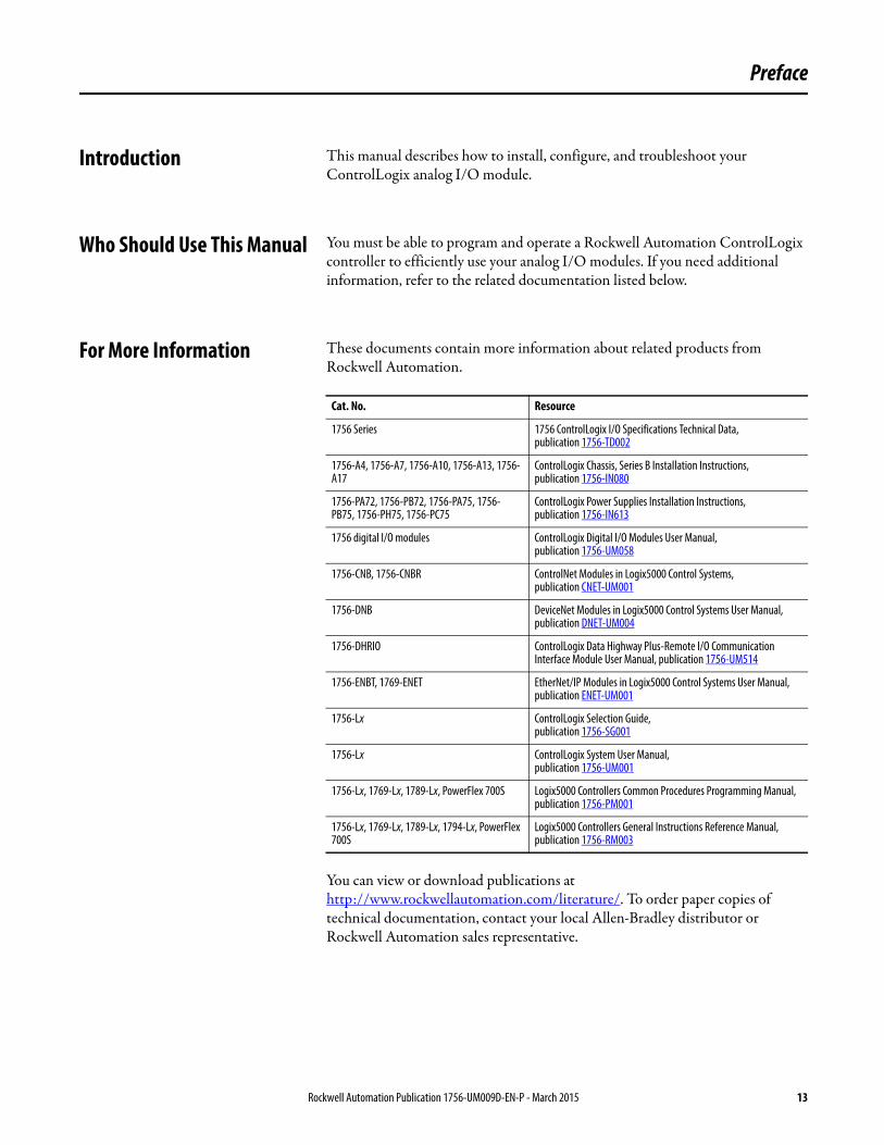
For More Information These documents contain more information about related products from Rockwell Automation.
You can view or download publications at http://www.rockwellautomation.com/literature/. To order paper copies of technical documentation, contact your local Allen-Bradley distributor or Rockwell Automation sales representative.
Cat. No. Resource
1756 Series 1756 ControlLogix I/O Specifications Technical Data, publication 1756-TD002
1756-A4, 1756-A7, 1756-A10, 1756-A13, 1756-A17
ControlLogix Chassis, Series B Installation Instructions, publication 1756-IN080
1756-PA72, 1756-PB72, 1756-PA75, 1756-PB75, 1756-PH75, 1756-PC75
ControlLogix Power Supplies Installation Instructions, publication 1756-IN613
1756 digital I/O modules ControlLogix Digital I/O Modules User Manual, publication 1756-UM058
1756-CNB, 1756-CNBR ControlNet Modules in Logix5000 Control Systems, publication CNET-UM001
1756-DNB DeviceNet Modules in Logix5000 Control Systems User Manual, publication DNET-UM004
1756-DHRIO ControlLogix Data Highway Plus-Remote I/O Communication Interface Module User Manual, publication 1756-UM514
1756-ENBT, 1769-ENET EtherNet/IP Modules in Logix5000 Control Systems User Manual, publication ENET-UM001
1756-Lx ControlLogix Selection Guide,publication 1756-SG001
1756-Lx ControlLogix System User Manual,publication 1756-UM001
1756-Lx, 1769-Lx, 1789-Lx, PowerFlex 700S Logix5000 Controllers Common Procedures Programming Manual, publication 1756-PM001
1756-Lx, 1769-Lx, 1789-Lx, 1794-Lx, PowerFlex 700S
Logix5000 Controllers General Instructions Reference Manual, publication 1756-RM003
Rockwell Automation Publication 1756-UM009D-EN-P - March 2015 13

Preface
Notes:
14 Rockwell Automation Publication 1756-UM009D-EN-P - March 2015
Chapter 1
What Are ControlLogix Analog I/O Modules?
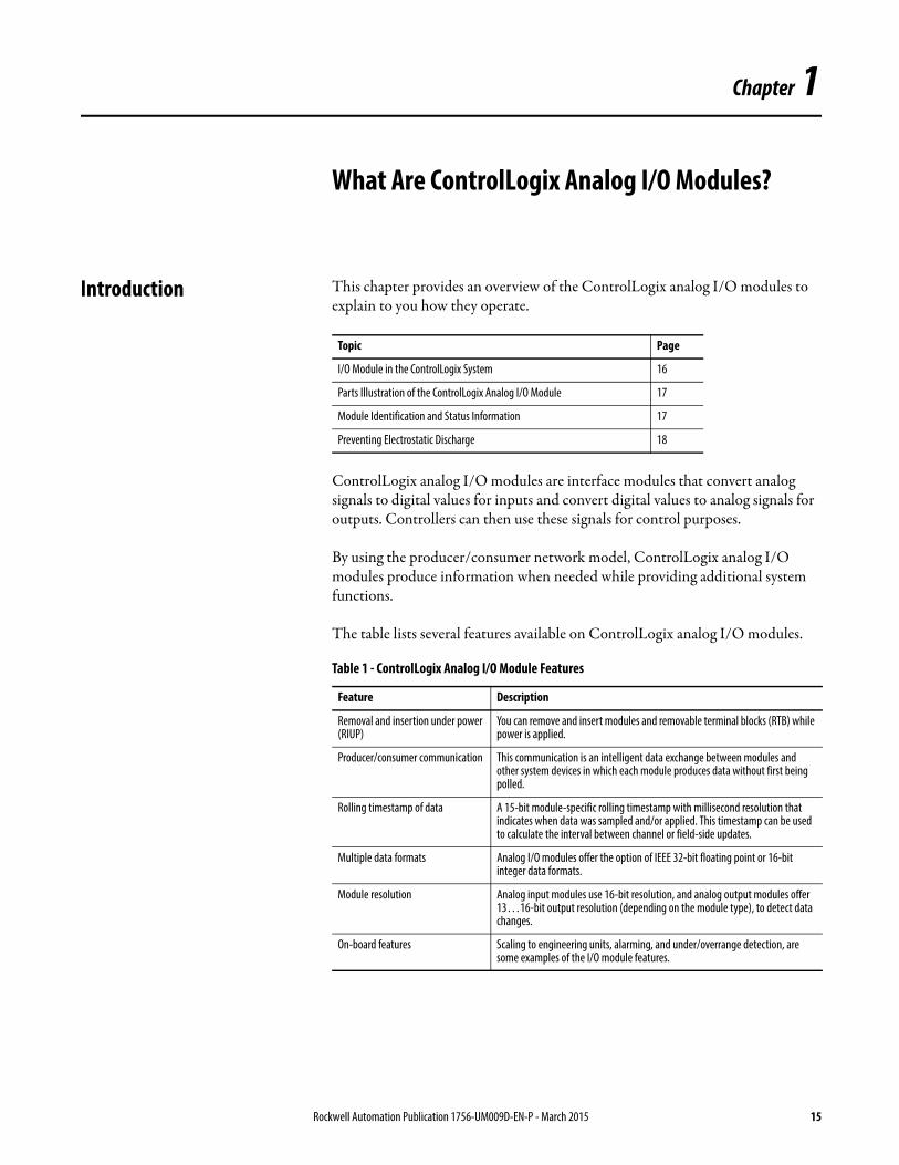
Introduction This chapter provides an overview of the ControlLogix analog I/O modules to explain to you how they operate.
ControlLogix analog I/O modules are interface modules that convert analog signals to digital values for inputs and convert digital values to analog signals for outputs. Controllers can then use these signals for control purposes.
By using the producer/consumer network model, ControlLogix analog I/O modules produce information when needed while providing additional system functions.
The table lists several features available on ControlLogix analog I/O modules.
Topic Page
I/O Module in the ControlLogix System 16
Parts Illustration of the ControlLogix Analog I/O Module 17
Module Identification and Status Information 17
Preventing Electrostatic Discharge 18
Table 1 - ControlLogix Analog I/O Module Features
Feature Description
Removal and insertion under power (RIUP)
You can remove and insert modules and removable terminal blocks (RTB) while power is applied.
Producer/consumer communication This communication is an intelligent data exchange between modules and other system devices in which each module produces data without first being polled.
Rolling timestamp of data A 15-bit module-specific rolling timestamp with millisecond resolution that indicates when data was sampled and/or applied. This timestamp can be used to calculate the interval between channel or field-side updates.
Multiple data formats Analog I/O modules offer the option of IEEE 32-bit floating point or 16-bit integer data formats.
Module resolution Analog input modules use 16-bit resolution, and analog output modules offer 13…16-bit output resolution (depending on the module type), to detect data changes.
On-board features Scaling to engineering units, alarming, and under/overrange detection, are some examples of the I/O module features.
Rockwell Automation Publication 1756-UM009D-EN-P - March 2015 15
Chapter 1 What Are ControlLogix Analog I/O Modules?
I/O Module in the ControlLogix System
ControlLogix modules mount in a ControlLogix chassis and use a removable terminal block (RTB) or a Bulletin 1492 interface module(1) cable to connect to all field-side wiring.
Before you install and use your module, do the following:
• Install and ground a 1756 chassis and power supply(2). To install these products, refer to the publications listed in For More Informationon page 13.
• Order and receive an RTB or IFM and its components for your application.
For the latest I/O module specifications, see the 1756 ControlLogix I/O Modules Technical Specifications, publication 1756-TD002.
Calibration ControlLogix analog I/O module ships from the factory with factory calibration. You can recalibrate the module calibration on a channel-by-channel or module-wide basis to increase accuracy in customer-specific applications, if necessary.
Coordinated system time (CST) time stamp of data
A 64-bit system clock places a time stamp on the transfer of data between the module and its owner-controller within the local chassis.
Agency Certification Full agency certification for in any application that requires approval.Agency certification varies depending on the catalog number. For the latest I/O module specifications, see the 1756 ControlLogix I/O Modules Technical Specifications, publication 1756-TD002.
Table 1 - ControlLogix Analog I/O Module Features
Feature Description
(1) The ControlLogix system has been agency certified using only the ControlLogix RTBs (1756-TBCH, 1756-TBNH, 1756-TBSH and 1756-TBS6H). Any application that requires agency certification of the ControlLogix system using other wiring termination methods can require application specific approval by the certifying agency. To see what analog interface modules are used with each ControlLogix analog I/O module, see Appendix E.
(2) In addition to standard ControlLogix power supplies, ControlLogix Redundant Power Supplies are also available for your application. For more information on these supplies, see the ControlLogix Selection Guide,publication 1756-SG001, or contact your local Rockwell Automation distributor or sales representative.
IMPORTANT RTBs and IFMs are not included with your module purchase.
16 Rockwell Automation Publication 1756-UM009D-EN-P - March 2015
What Are ControlLogix Analog I/O Modules? Chapter 1
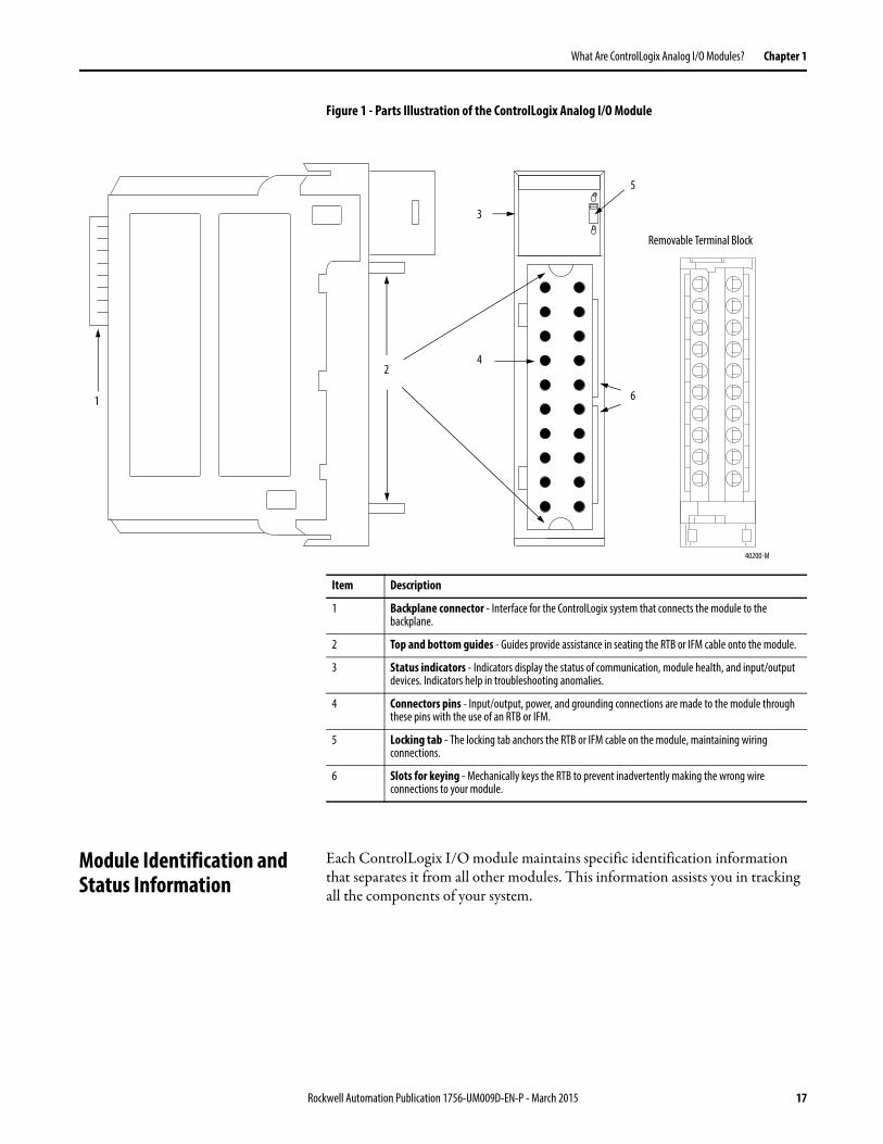
Figure 1 - Parts Illustration of the ControlLogix Analog I/O Module
Module Identification and Status Information
Each ControlLogix I/O module maintains specific identification information that separates it from all other modules. This information assists you in tracking all the components of your system.
Removable Terminal Block
1
2
3
4
5
6
40200-M
Item Description
1 Backplane connector - Interface for the ControlLogix system that connects the module to the backplane.
2 Top and bottom guides - Guides provide assistance in seating the RTB or IFM cable onto the module.
3 Status indicators - Indicators display the status of communication, module health, and input/output devices. Indicators help in troubleshooting anomalies.
4 Connectors pins - Input/output, power, and grounding connections are made to the module through these pins with the use of an RTB or IFM.
5 Locking tab - The locking tab anchors the RTB or IFM cable on the module, maintaining wiring connections.
6 Slots for keying - Mechanically keys the RTB to prevent inadvertently making the wrong wire connections to your module.
Rockwell Automation Publication 1756-UM009D-EN-P - March 2015 17
Chapter 1 What Are ControlLogix Analog I/O Modules?
For example, you can track module identification information to be aware of exactly what modules are in any ControlLogix rack at any time. While retrieving module identity, you can also retrieve the module’s status.
Preventing Electrostatic Discharge
This module is sensitive to electrostatic discharge.
Table 2 - Module Identification and Status Information
Item Description
Product Type Module’s product type, such as Analog I/Oor Digital I/O module
Catalog Code Module’s catalog number
Major Revision Module’s major revision number
Minor Revision Module’s minor revision number
Status Module’s status that shows the following information:• Controller ownership (if any)• Whether module has been configured• Device Specific Status, such as:• Self-Test• Flash update in progress• Communications fault• Not owned (outputs in program mode)• Internal fault (need flash update)• Run mode• Program mode (output mods only)• Minor recoverable fault• Minor unrecoverable fault• Major recoverable fault• Major unrecoverable fault
Vendor ID Module manufacturer vendor, for example Allen-Bradley
Serial Number Module serial number
Length of ASCII Text String Number of characters in module’s text string
ASCII Text String Number of characters in module’s text string
IMPORTANT You must perform a WHO service to retrieve this information.
ATTENTION: This equipment is sensitive to electrostatic discharge, which can cause internal damage and affect normal operation. Follow these guidelines when you handle this equipment:• Touch a grounded object to discharge potential static.• Wear an approved grounding wriststrap.• Do not touch connectors or pins on component boards.• Do not touch circuit components inside the equipment.• If available, use a static-safe workstation.• When not in use, store the equipment in appropriate static-safe
packaging.
18 Rockwell Automation Publication 1756-UM009D-EN-P - March 2015
Chapter 2
Analog I/O Operation in theControlLogix System
Introduction I/O modules are interfaces between the controller and the field devices that comprise the ControlLogix system. Analog signals, which are continuous, are converted by the module and used by the controller to mandate field-device results.
This chapter describes how analog I/O modules operate within the ControlLogix system.
Ownership Every I/O module in the ControlLogix system must be owned by a ControlLogix controller. This owner-controller:
• stores configuration data for every module that it owns.• can be local or remote in regard to the I/O module’s position.• sends the I/O module configuration data to define the module’s behavior
and begin operation within the control system.
Each ControlLogix I/O module must continuously maintain communication with its owner to operate normally.
Topic Page
Ownership 19
Using RSNetWorx and RSLogix 5000 Software 20
Direct Connections 21
Input Module Operation 22
Input Modules in a Local Chassis 22
Real Time Sample (RTS) 22
Requested Packet Interval (RPI) 23
Input Modules in a Remote Chassis 25
Output Module Operation 27
Output Modules in a Local Chassis 27
Output Modules in a Remote Chassis 28
Listen-only Mode 30
Multiple Owners of Input Modules 31
Configuration Changes in an Input Module with Multiple Owners 32
Rockwell Automation Publication 1756-UM009D-EN-P - March 2015 19
Chapter 2 Analog I/O Operation in the ControlLogix System
Typically, each module in the system has one owner only. Input modules can have more than one owner. Output modules, however, are limited to a single owner.
For more information on the increased flexibility provided by multiple owners and the ramifications of using multiple owners, see Configuration Changes in an Input Module with Multiple Owners on page 32.
Using RSNetWorx and RSLogix 5000 Software
The I/O configuration portion of the RSLogix5000 programming software generates the configuration data for each I/O module in the control system, whether the module is in a local or remote chassis. A remote chassis, also known as networked, contains the I/O module but not the module’s owner-controller. A remote chassis can be connected to the controller via a scheduled connection on the ControlNet network or anEtherNet/IP network.
RSLogix 5000 configuration data is transferred to the controller during the program download and subsequently transferred to the appropriate I/O modules. I/O modules in the local chassis, and modules in a remote chassis connected via the EtherNet/IP network, or unscheduled connections on the ControlNet network, are ready to run as soon as the configuration data has been downloaded. However, to enable scheduled connections to I/O modules on the ControlNet network, you must schedule the network by using RSNetWorx for ControlNet software.
Running RSNetWorx software transfers configuration data to I/O modules on a scheduled ControlNet network and establishes a network update time (NUT) for the ControlNet network that is compliant with the desired communication options specified for each module during configuration.
Anytime a controller references a scheduled connection to I/O modules on a scheduled ControlNet network, you must run RSNetWorx software to configure the ControlNet network.
Refer to the following general steps when configuring I/O modules.
1. Configure all I/O modules for a given controller by using RSLogix 5000 programming software and download that information to the controller.
2. If the I/O configuration data references a scheduled connection to a module in a remote chassis connected via the ControlNet network, run RSNetWorx for ControlNet software to schedule the network.
20 Rockwell Automation Publication 1756-UM009D-EN-P - March 2015
Analog I/O Operation in the ControlLogix System Chapter 2
3. After running RSNetWorx software, perform an online save of the RSLogix 5000 project so the configuration information that RSNetWorx software sends to the controller is saved.
Direct Connections ControlLogix analog I/O modules use direct connections only.
A direct connection is a real-time data transfer link between the controller and the device that occupies the slot that the configuration data references. When module configuration data is downloaded to an owner-controller, the controller attempts to establish a direct connection to each of the modules referenced by the data.
If a controller has configuration data referencing a slot in the control system, the controller periodically checks for the presence of a device there. When a device’s presence is detected there, the controller automatically sends the configuration data, and one of the following events occurs:
• If the data is appropriate to the module found in the slot, a connection is made and operation begins.
• If the configuration data is not appropriate, the data is rejected and an error message displays in the software. In this case, the configuration data can be inappropriate for any of a number of reasons.
For example, a module’s configuration data can be appropriate except for a mismatch in electronic keying that prevents normal operation.
The controller maintains and monitors its connection with a module. Any break in the connection, such as removal of the module from the chassis while under power, causes the controller to set fault status bits in the data area associated with the module. The RSLogix 5000 programming software monitors this data area to annunciate the module’s failures.
IMPORTANT You must run RSNetWorx for ControlNet software whenever a new I/O module is added to a scheduled ControlNet chassis. When a module is permanently removed from a remote chassis, we recommend that you run RSNetWorx for ControlNet software to reschedule the network and optimize the allocation of network bandwidth.
Rockwell Automation Publication 1756-UM009D-EN-P - March 2015 21
Chapter 2 Analog I/O Operation in the ControlLogix System
Input Module Operation In traditional I/O systems, controllers poll input modules to obtain their input status. In the ControlLogix system, a controller does not poll analog input modules after a connection is established. Instead, the modules multicast their data periodically. The frequency depends on the options chosen during configuration and where in the control system that input module physically resides.
An input module’s behavior varies depending upon whether it operates in the local chassis or in a remote chassis. The following sections detail the differences in data transfers between these set-ups.
Input Modules in a Local Chassis
When a module resides in the same chassis as the owner-controller, the following two configuration parameters affect how and when an input module produces data:
• Real Time Sample (RTS)• Requested Packet Interval (RPI)
Real Time Sample (RTS)
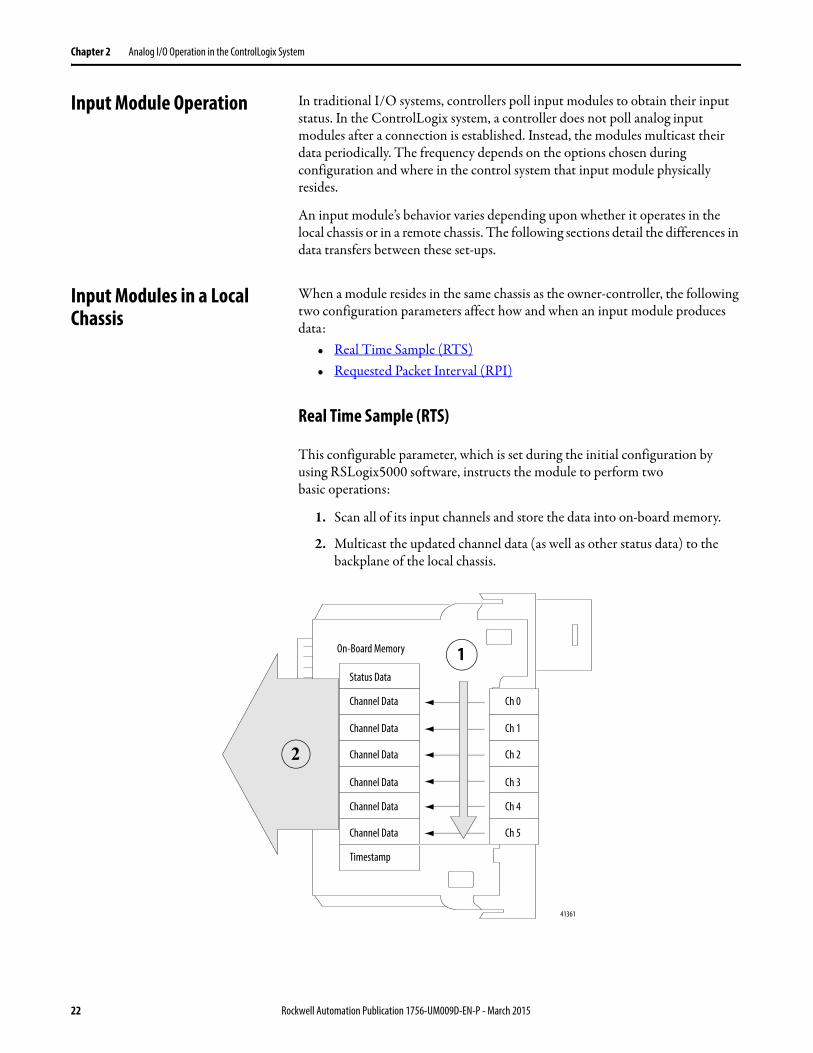
This configurable parameter, which is set during the initial configuration by using RSLogix5000 software, instructs the module to perform twobasic operations:
1. Scan all of its input channels and store the data into on-board memory.
2. Multicast the updated channel data (as well as other status data) to the backplane of the local chassis.
On-Board Memory
Status Data
Channel Data
Channel Data
Channel Data
Channel Data
Channel Data
Channel Data
Ch 0
Ch 1
Ch 2
Ch 3
Ch 4
Ch 5
Timestamp
41361
1
2
22 Rockwell Automation Publication 1756-UM009D-EN-P - March 2015
Analog I/O Operation in the ControlLogix System Chapter 2
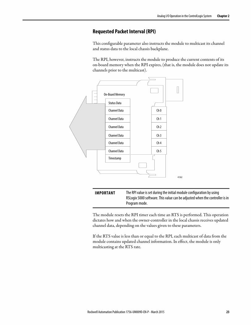
Requested Packet Interval (RPI)
This configurable parameter also instructs the module to multicast its channel and status data to the local chassis backplane.
The RPI, however, instructs the module to produce the current contents of its on-board memory when the RPI expires, (that is, the module does not update its channels prior to the multicast).
The module resets the RPI timer each time an RTS is performed. This operation dictates how and when the owner-controller in the local chassis receives updated channel data, depending on the values given to these parameters.
If the RTS value is less than or equal to the RPI, each multicast of data from the module contains updated channel information. In effect, the module is only multicasting at the RTS rate.
On-Board Memory
Status Data
Channel Data
Channel Data
Channel Data
Channel Data
Channel Data
Channel Data
Ch 0
Ch 1
Ch 2
Ch 3
Ch 4
Ch 5
Timestamp
41362
IMPORTANT The RPI value is set during the initial module configuration by using RSLogix 5000 software. This value can be adjusted when the controller is in Program mode.
Rockwell Automation Publication 1756-UM009D-EN-P - March 2015 23
Chapter 2 Analog I/O Operation in the ControlLogix System
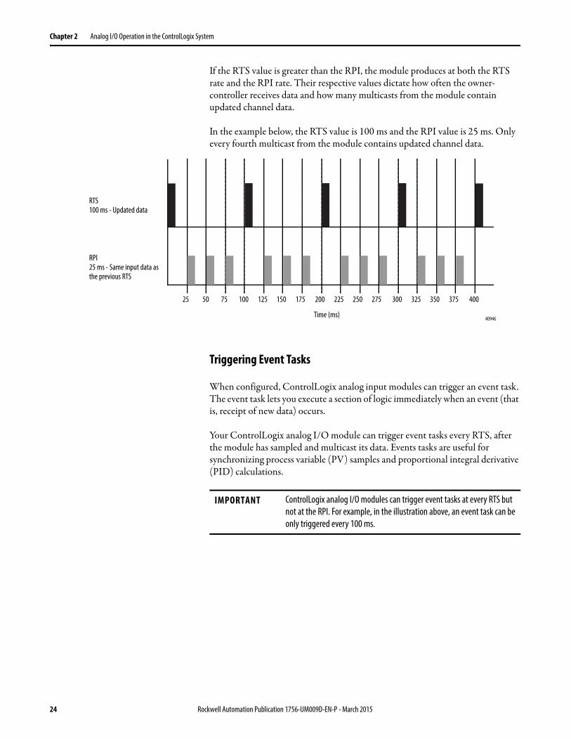
If the RTS value is greater than the RPI, the module produces at both the RTS rate and the RPI rate. Their respective values dictate how often the owner-controller receives data and how many multicasts from the module contain updated channel data.
In the example below, the RTS value is 100 ms and the RPI value is 25 ms. Only every fourth multicast from the module contains updated channel data.
Triggering Event Tasks
When configured, ControlLogix analog input modules can trigger an event task. The event task lets you execute a section of logic immediately when an event (that is, receipt of new data) occurs.
Your ControlLogix analog I/O module can trigger event tasks every RTS, after the module has sampled and multicast its data. Events tasks are useful for synchronizing process variable (PV) samples and proportional integral derivative (PID) calculations.
RTS100 ms - Updated data
RPI25 ms - Same input data as the previous RTS
25 50 75 100 125 150 175 200 225 250 275 300 325 350 375 400
Time (ms) 40946
IMPORTANT ControlLogix analog I/O modules can trigger event tasks at every RTS but not at the RPI. For example, in the illustration above, an event task can be only triggered every 100 ms.
24 Rockwell Automation Publication 1756-UM009D-EN-P - March 2015
Analog I/O Operation in the ControlLogix System Chapter 2
Input Modulesin a Remote Chassis
If an input module physically resides in a remote chassis, the role of the RPI and the module’s RTS behavior change slightly with respect to getting data to the owner-controller, depending on what network type you are using to connect to the modules.
Remote Input Modules Connected Via the ControlNet Network
When remote analog I/O modules are connected to the owner-controller via a scheduled ControlNet network, the RPI and RTS intervals still define when the module multicasts data within its own chassis (as described in the previous section). However, only the value of the RPI determines how often the owner-controller receives it over the network.
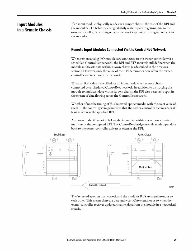
When an RPI value is specified for an input module in a remote chassis connected by a scheduled ControlNet network, in addition to instructing the module to multicast data within its own chassis, the RPI also ‘reserves’ a spot in the stream of data flowing across the ControlNet network.
Whether of not the timing of this ‘reserved’ spot coincides with the exact value of the RPI, the control system guarantees that the owner-controller receives data at least as often as the specified RPI.
As shown in the illustration below, the input data within the remote chassis is multicast at the configured RPI. The ControlNet bridge module sends input data back to the owner-controller at least as often as the RPI.
The ‘reserved’ spot on the network and the module’s RTS are asynchronous to each other. This means there are best and worst Case scenarios as to when the owner-controller receives updated channel data from the module in a networked chassis.
ControlNet network
Multicast data
40947
Local Chassis Remote Chassis
Rockwell Automation Publication 1756-UM009D-EN-P - March 2015 25
Chapter 2 Analog I/O Operation in the ControlLogix System
Best Case RTS Scenario
In the best case scenario, the module performs an RTS multicast with updated channel data just before the ‘reserved’ network slot is made available. In this case, the remotely-located owner-controller receives the data almost immediately.
Worst Case RTS Scenario
In the worst case scenario, the module performs an RTS multicast just after the ‘reserved’ network slot has passed. In this case, the owner-controller does not receive data until the next scheduled network slot.
Remote Input Modules Connected Via the EtherNet/IP Network
When remote analog input modules are connected to the owner-controller via an EtherNet/IP network, data is transferred to the owner-controller in the following way:
• At the RTS or RPI (whichever is faster), the module broadcasts data within its own chassis.
• The 1756 Ethernet bridge module in the remote chassis immediately sends the module’s data over the network to the owner-controller as long as it has not sent data within a time frame that is one-quarter the value of the analog input module’s RPI.
For example, if an analog input module uses an RPI = 100 ms, the Ethernet module sends module data immediately on receiving it if another data packet was not sent within the last 25 ms.
The Ethernet module either multicasts the module’s data to all devices on the network or unicasts to a specific owner-controller depending on the setting of the Unicast box, as shown on page 192.
TIP Because it is the RPI and not the RTS that dictates when the module’s data is sent over the network, we recommend the RPI value be set less than or equal to the RTS to make sure that updated channel data is received by the owner-controller with each receipt of data.
TIP For more information, see the Guidelines to Specify an RPI Rate for I/O Modules section in the Logix5000 Controllers Design Considerations Reference Manual, publication 1756-RM094.
26 Rockwell Automation Publication 1756-UM009D-EN-P - March 2015
Analog I/O Operation in the ControlLogix System Chapter 2
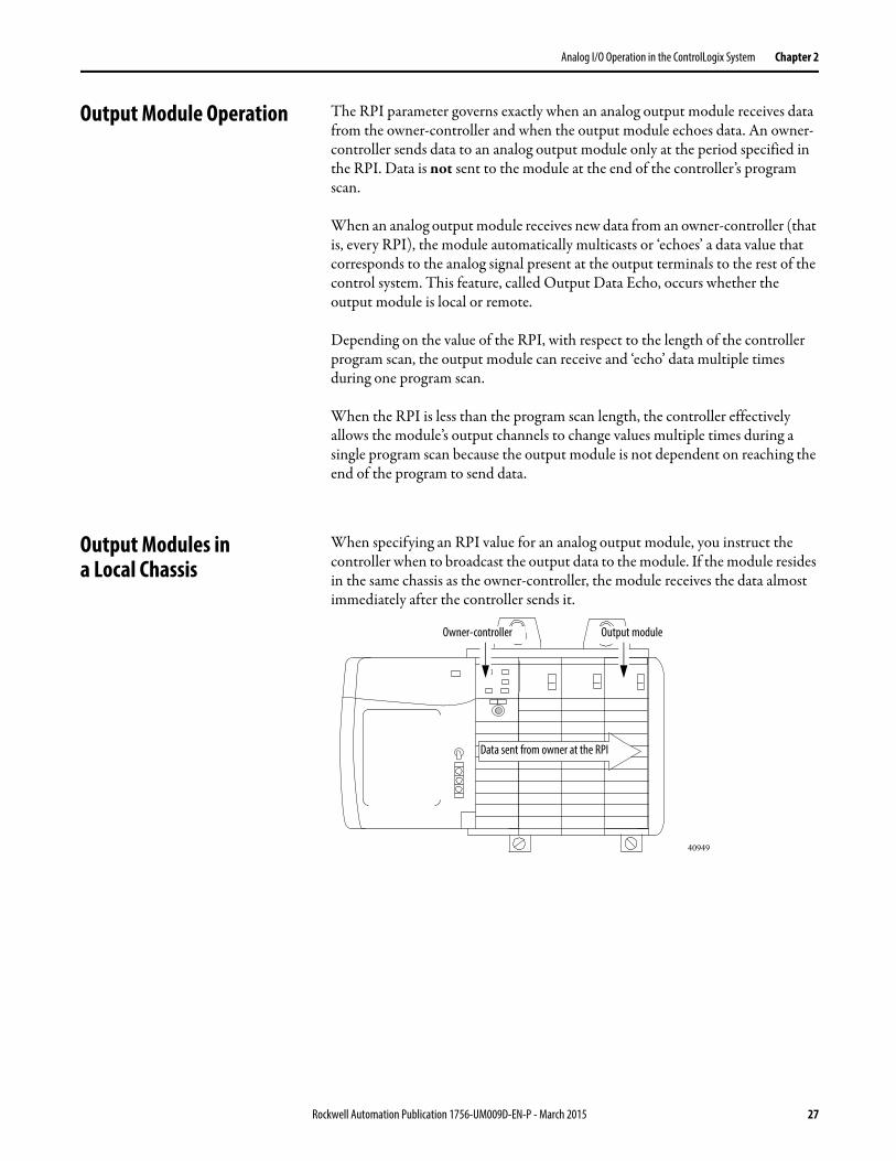
Output Module Operation The RPI parameter governs exactly when an analog output module receives data from the owner-controller and when the output module echoes data. An owner-controller sends data to an analog output module only at the period specified in the RPI. Data is not sent to the module at the end of the controller’s program scan.
When an analog output module receives new data from an owner-controller (that is, every RPI), the module automatically multicasts or ‘echoes’ a data value that corresponds to the analog signal present at the output terminals to the rest of the control system. This feature, called Output Data Echo, occurs whether the output module is local or remote.
Depending on the value of the RPI, with respect to the length of the controller program scan, the output module can receive and ‘echo’ data multiple times during one program scan.
When the RPI is less than the program scan length, the controller effectively allows the module’s output channels to change values multiple times during a single program scan because the output module is not dependent on reaching the end of the program to send data.
Output Modules ina Local Chassis
When specifying an RPI value for an analog output module, you instruct the controller when to broadcast the output data to the module. If the module resides in the same chassis as the owner-controller, the module receives the data almost immediately after the controller sends it.
40949
Data sent from owner at the RPI
Owner-controller Output module
Rockwell Automation Publication 1756-UM009D-EN-P - March 2015 27
Chapter 2 Analog I/O Operation in the ControlLogix System
Output Modules ina Remote Chassis
If an output module resides in a remote chassis, the role of the RPI changes slightly with respect to getting data from the owner-controller, depending on what network type you are using to connect to the modules.
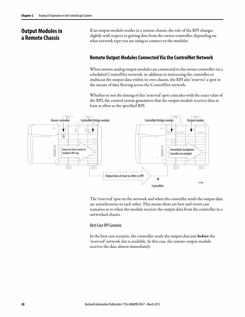
Remote Output Modules Connected Via the ControlNet Network
When remote analog output modules are connected to the owner-controller via a scheduled ControlNet network, in addition to instructing the controller to multicast the output data within its own chassis, the RPI also ‘reserves’ a spot in the stream of data flowing across the ControlNet network.
Whether or not the timing of this ‘reserved’ spot coincides with the exact value of the RPI, the control system guarantees that the output module receives data at least as often as the specified RPI.
The ‘reserved’ spot on the network and when the controller sends the output data are asynchronous to each other. This means there are best and worst case scenarios as to when the module receives the output data from the controller in a networked chassis.
Best Case RPI Scenario
In the best case scenario, the controller sends the output data just before the ‘reserved’ network slot is available. In this case, the remote output module receives the data almost immediately.
ControlNet
Output data at least as often as RPI
Immediate backplane transfers to module
Data sent from owner at module’s RPI rate
Owner-controller ControlNet Bridge module ControlNet Bridge module Output module
41360
28 Rockwell Automation Publication 1756-UM009D-EN-P - March 2015
Analog I/O Operation in the ControlLogix System Chapter 2
Worst Case RPI Scenario
In the worst case scenario, the controller sends the data just after the ‘reserved’ network slot has passed. In this case, the module does not receive the data until the next scheduled network slot.
Remote Output Modules Connected Via the EtherNet/IP Network
When remote analog output modules are connected to the owner-controller via an EtherNet/IP network, the controller multicasts data in thefollowing ways:
• At the RPI, the owner-controller multicasts data within its own chassis.
• When the RPI timer expires or a programmed Immediate Output (IOT) instruction is executed. An IOT sends data immediately and resets the RPI timer.
IMPORTANT These best and worst case scenarios indicate the time required for output data to transfer from the controller to the module once the controller has produced it.The scenarios do not take into account when the module receives new data (updated by the user program) from the controller. That is a function of the length of the user program and its asynchronous relationship with the RPI.
Rockwell Automation Publication 1756-UM009D-EN-P - March 2015 29
Chapter 2 Analog I/O Operation in the ControlLogix System
Listen-only Mode Any controller in the system can listen to the data from any I/O module (that is, input data or ‘echoed’ output data) even if the controller does not own the module. In other words, the controller does not have to own a module’s configuration data to listen to it.
During the I/O configuration process, you can specify one of several ‘Listen-Only’ modes in the Comm Format box on the New Module dialog box. See page 185 for more Comm Format details.
Choosing a ‘Listen-Only’ mode option allows the controller and module to establish communications without the controller sending any configuration data. In this instance, another controller owns the module being listened to.
IMPORTANT If a ‘Listen-Only’ connection is being used by any controller to the module, any connections over the Ethernet network cannot use the Unicast option. See the Unicast box on page 192for details.The ‘Listen-Only’ controller continues to receive multicast data from the I/O module as long as a connection between an owner-controller and I/O module is maintainedIf the connection between all owner-controllers and the module is broken, the module stops multicasting data and connections to all ‘Listening controllers’ are also broken.
30 Rockwell Automation Publication 1756-UM009D-EN-P - March 2015
Analog I/O Operation in the ControlLogix System Chapter 2
Multiple Ownersof Input Modules
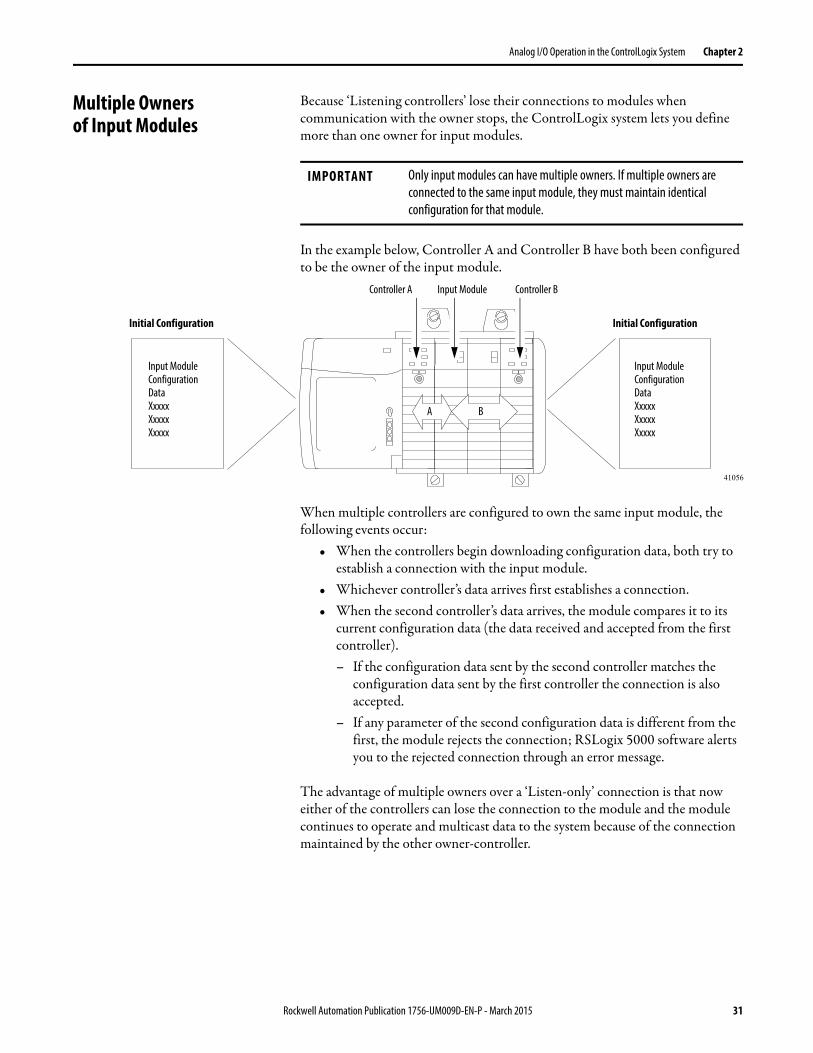
Because ‘Listening controllers’ lose their connections to modules when communication with the owner stops, the ControlLogix system lets you define more than one owner for input modules.
In the example below, Controller A and Controller B have both been configured to be the owner of the input module.
When multiple controllers are configured to own the same input module, the following events occur:
• When the controllers begin downloading configuration data, both try to establish a connection with the input module.
• Whichever controller’s data arrives first establishes a connection.• When the second controller’s data arrives, the module compares it to its
current configuration data (the data received and accepted from the first controller).– If the configuration data sent by the second controller matches the
configuration data sent by the first controller the connection is also accepted.
– If any parameter of the second configuration data is different from the first, the module rejects the connection; RSLogix 5000 software alerts you to the rejected connection through an error message.
The advantage of multiple owners over a ‘Listen-only’ connection is that now either of the controllers can lose the connection to the module and the module continues to operate and multicast data to the system because of the connection maintained by the other owner-controller.
IMPORTANT Only input modules can have multiple owners. If multiple owners are connected to the same input module, they must maintain identical configuration for that module.
Input Module Configuration DataXxxxxXxxxxXxxxx
Input Module Configuration DataXxxxxXxxxxXxxxx
41056
Initial Configuration Initial Configuration
Controller A Controller BInput Module
A B
Rockwell Automation Publication 1756-UM009D-EN-P - March 2015 31
Chapter 2 Analog I/O Operation in the ControlLogix System
Configuration Changes in an Input Module with Multiple Owners
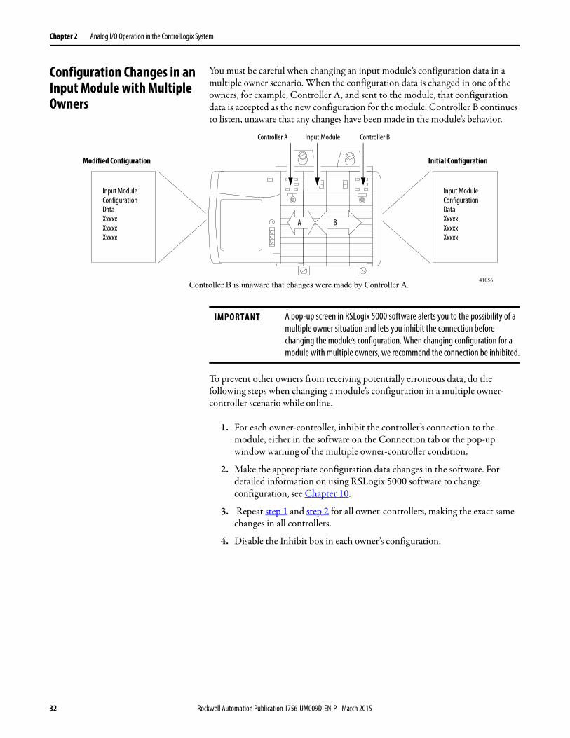
You must be careful when changing an input module’s configuration data in a multiple owner scenario. When the configuration data is changed in one of the owners, for example, Controller A, and sent to the module, that configuration data is accepted as the new configuration for the module. Controller B continues to listen, unaware that any changes have been made in the module’s behavior.
To prevent other owners from receiving potentially erroneous data, do the following steps when changing a module’s configuration in a multiple owner-controller scenario while online.
1. For each owner-controller, inhibit the controller’s connection to the module, either in the software on the Connection tab or the pop-up window warning of the multiple owner-controller condition.
2. Make the appropriate configuration data changes in the software. For detailed information on using RSLogix 5000 software to change configuration, see Chapter 10.
3. Repeat step 1 and step 2 for all owner-controllers, making the exact same changes in all controllers.
4. Disable the Inhibit box in each owner’s configuration.
Input Module Configuration DataXxxxxXxxxxXxxxx
Input Module Configuration DataXxxxxXxxxxXxxxx
41056
Modified Configuration Initial Configuration
Controller A Controller BInput Module
A B
Controller B is unaware that changes were made by Controller A.
IMPORTANT A pop-up screen in RSLogix 5000 software alerts you to the possibility of a multiple owner situation and lets you inhibit the connection before changing the module’s configuration. When changing configuration for a module with multiple owners, we recommend the connection be inhibited.
32 Rockwell Automation Publication 1756-UM009D-EN-P - March 2015
Chapter 3
ControlLogix Analog I/O Module Features
Introduction This chapter describes features that are common to all ControlLogix analog I/O modules.
ControlLogix analog input modules convert an analog signal of either volts, millivolts, milliamps, or ohms that is connected to the module's screw terminals into a digital value.
The digital value that represents the magnitude of the analog signal is then transmitted on the backplane to either a controller or other control entities.
ControlLogix output modules convert a digital value that is delivered to the module via the backplane into an analog signal of -10.5…10.5 voltsor 0…21 milliamps.
The digital value represents the magnitude of the desired analog signal. The module converts the digital value into an analog signal and provides this signal on the module's screw terminals.
Common AnalogI/O Features
The following table lists common features for analog I/O modules.
Feature Page
Removal and Insertion Under Power (RIUP) 34
Module Fault Reporting 34
Configurable Software 34
Electronic Keying 34
Access to System Clock for Timestamp Functions 36
Rolling Timestamp 36
Producer/Consumer Model 36
Status Indicator Information 37
Full Class I Division 2 Compliance 37
Agency Certification 37
Field Calibration 37
Sensor Offset 38
Latching of Alarms 38
Rockwell Automation Publication 1756-UM009D-EN-P - March 2015 33
Chapter 3 ControlLogix Analog I/O Module Features
Removal and Insertion Under Power (RIUP)
All ControlLogix I/O modules can be inserted and removed from the chassis while power is applied. This feature allows greater availability of the overall control system because, while the module is being removed or inserted, there is no additional disruption to the rest of the controlled process.
Module Fault Reporting
ControlLogix analog I/O modules provide both hardware and software indication when a module fault has occurred. Each module has a status fault indicator. RSLogix 5000 software graphically displays this fault and includes a fault message that describes the nature of the fault. This feature lets you determine how your module has been affected and what action is to be taken to resume normal operation.
For more information on module fault reporting as it relates to specific modules, see the chapter describing that module, either chapter 4, 5, 6, 7 or 8.
Configurable Software
The RSLogix 5000 software uses a custom, easily understood interface to write configuration. All module features are enabled or disabled through the I/O configuration portion of the software.
You can also use the software to interrogate any module in the system to retrieve:• serial number.• revision information.• catalog number.• vendor identification.• error/fault information.• diagnostic counters.
By eliminating such tasks as setting hardware switches and jumpers, the software makes module configuration easier and more reliable.
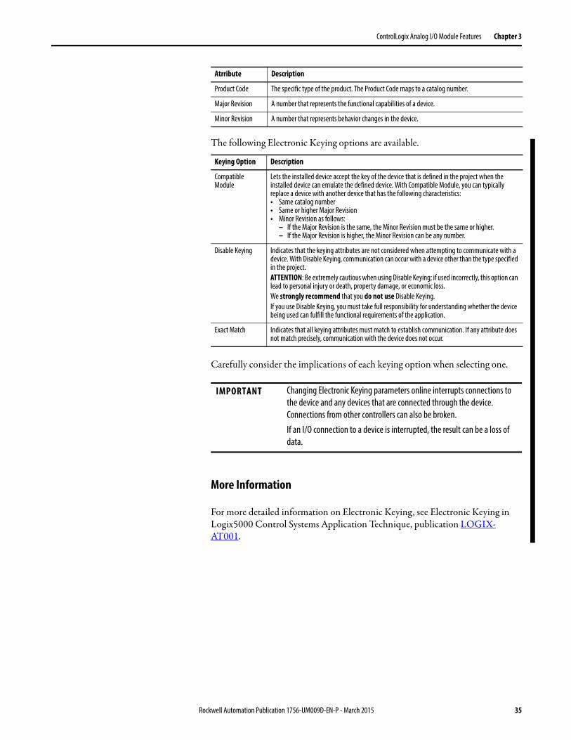
Electronic Keying Electronic Keying reduces the possibility that you use the wrong device in a control system. It compares the device defined in your project to the installed device. If keying fails, a fault occurs. These attributes are compared.
Atrribute Description
Vendor The device manufacturer.
Device Type The general type of the product, for example, digital I/O module.
34 Rockwell Automation Publication 1756-UM009D-EN-P - March 2015
ControlLogix Analog I/O Module Features Chapter 3
The following Electronic Keying options are available.
Carefully consider the implications of each keying option when selecting one.
More Information
For more detailed information on Electronic Keying, see Electronic Keying in Logix5000 Control Systems Application Technique, publication LOGIX-AT001.
Product Code The specific type of the product. The Product Code maps to a catalog number.
Major Revision A number that represents the functional capabilities of a device.
Minor Revision A number that represents behavior changes in the device.
Keying Option Description
Compatible Module
Lets the installed device accept the key of the device that is defined in the project when the installed device can emulate the defined device. With Compatible Module, you can typically replace a device with another device that has the following characteristics: • Same catalog number• Same or higher Major Revision• Minor Revision as follows:
– If the Major Revision is the same, the Minor Revision must be the same or higher.– If the Major Revision is higher, the Minor Revision can be any number.
Disable Keying Indicates that the keying attributes are not considered when attempting to communicate with a device. With Disable Keying, communication can occur with a device other than the type specified in the project.ATTENTION: Be extremely cautious when using Disable Keying; if used incorrectly, this option can lead to personal injury or death, property damage, or economic loss. We strongly recommend that you do not use Disable Keying. If you use Disable Keying, you must take full responsibility for understanding whether the device being used can fulfill the functional requirements of the application.
Exact Match Indicates that all keying attributes must match to establish communication. If any attribute does not match precisely, communication with the device does not occur.
IMPORTANT Changing Electronic Keying parameters online interrupts connections to the device and any devices that are connected through the device. Connections from other controllers can also be broken.If an I/O connection to a device is interrupted, the result can be a loss of data.
Atrribute Description
Rockwell Automation Publication 1756-UM009D-EN-P - March 2015 35
Chapter 3 ControlLogix Analog I/O Module Features
Access to System Clock for Timestamp Functions
Controllers within the ControlLogix chassis maintain a system clock. This clock is also known as the coordinated system time (CST). You can configure your analog I/O modules to access this clock and timestamp input data or output echo data when the module multicasts to the system. You decide how to timestamp data when you choose a Communication Format on the New Module dialog box. For more information, see page 185.
This feature provides accurate calculations between events to help you identify the sequence of events in either fault conditions or in the course of normal I/O operations. The system clock can be used between multiple modules in the same chassis.
In systems using an EtherNet/IP network and 1588 Grand Master time, the value of this timestamp still is the CST time. You must convert this CST value to Grand Master time in the controller.
Rolling Timestamp
Each module maintains a rolling timestamp that is unrelated to the CST. The rolling timestamp is a continuously running 15-bit timer that countsin milliseconds.
For input modules, whenever a module scans its channels, it also records the value of the rolling timestamp at that time. The user program can then use the last two rolling timestamp values and calculate the interval between receipt of data or the time when new data has been received.
For output modules, the rolling timestamp value is only updated when new values are applied to the Digital to Analog Converter (DAC).
Producer/Consumer Model
By using the Producer/Consumer model, ControlLogix I/O modules can produce data without having been polled by a controller first. The modules produce the data and any owner or listen-only controller device can decide to consume it.
For example, an input module produces data and any number of processors can consume the data at the same time. This eliminates the need for one processor to send the data to another processor.
36 Rockwell Automation Publication 1756-UM009D-EN-P - March 2015
ControlLogix Analog I/O Module Features Chapter 3
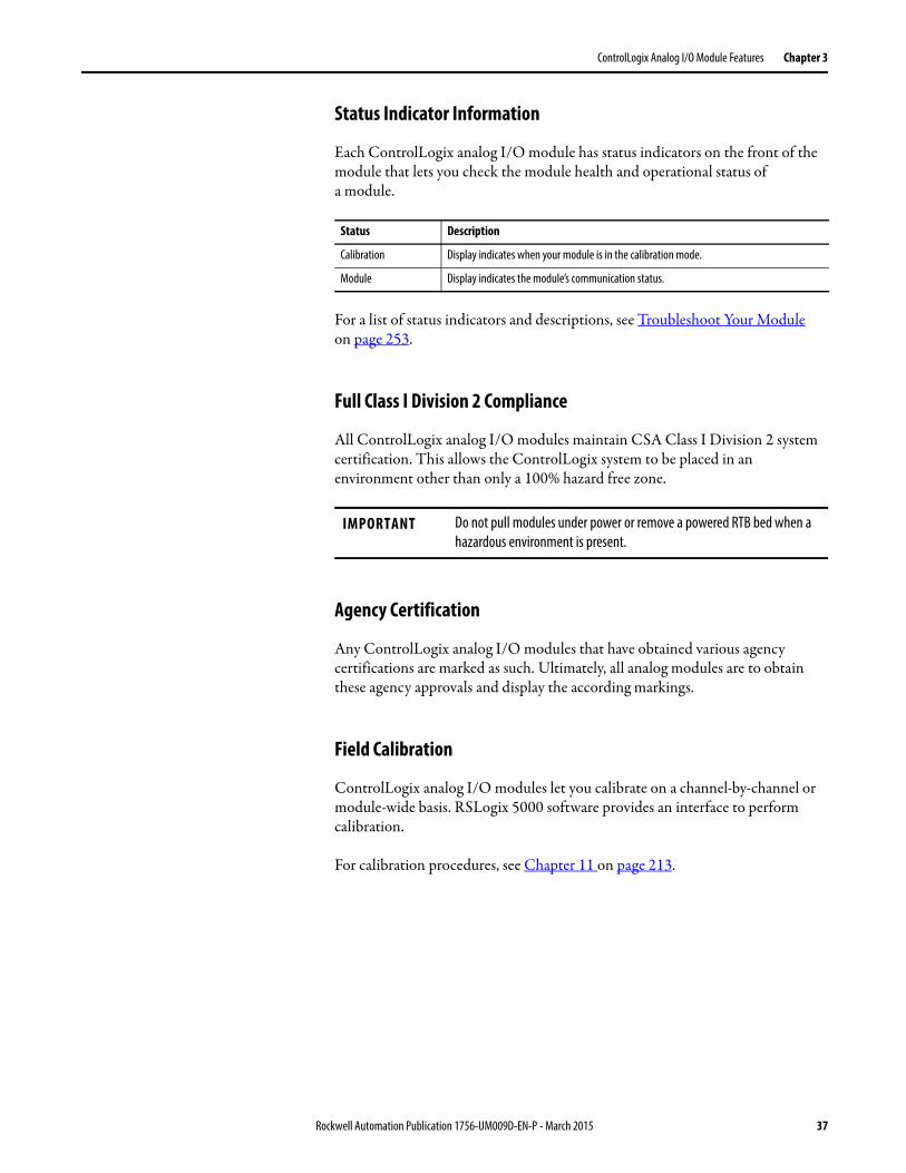
Status Indicator Information
Each ControlLogix analog I/O module has status indicators on the front of the module that lets you check the module health and operational status ofa module.
For a list of status indicators and descriptions, see Troubleshoot Your Moduleon page 253.
Full Class I Division 2 Compliance
All ControlLogix analog I/O modules maintain CSA Class I Division 2 system certification. This allows the ControlLogix system to be placed in an environment other than only a 100% hazard free zone.
Agency Certification
Any ControlLogix analog I/O modules that have obtained various agency certifications are marked as such. Ultimately, all analog modules are to obtain these agency approvals and display the according markings.
Field Calibration
ControlLogix analog I/O modules let you calibrate on a channel-by-channel or module-wide basis. RSLogix 5000 software provides an interface to perform calibration.
For calibration procedures, see Chapter 11 on page 213.
Status Description
Calibration Display indicates when your module is in the calibration mode.
Module Display indicates the module’s communication status.
IMPORTANT Do not pull modules under power or remove a powered RTB bed when a hazardous environment is present.
Rockwell Automation Publication 1756-UM009D-EN-P - March 2015 37
Chapter 3 ControlLogix Analog I/O Module Features
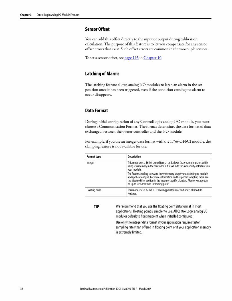
Sensor Offset
You can add this offset directly to the input or output during calibration calculation. The purpose of this feature is to let you compensate for any sensor offset errors that exist. Such offset errors are common in thermocouple sensors.
To set a sensor offset, see page 193 in Chapter 10.
Latching of Alarms
The latching feature allows analog I/O modules to latch an alarm in the set position once it has been triggered, even if the condition causing the alarm to occur disappears.
Data Format
During initial configuration of any ControlLogix analog I/O module, you must choose a Communication Format. The format determines the data format of data exchanged between the owner-controller and the I/O module.
For example, if you use an integer data format with the 1756-OF6CI module, the clamping feature is not available for use.
Format type Description
Integer This mode uses a 16-bit signed format and allows faster sampling rates while using less memory in the controller but also limits the availability of features on your module.The faster sampling rates and lower memory usage vary according to module and application type. For more information on the specific sampling rates, see the Module Filter section in the module-specific chapters. Memory usage can be up to 50% less than in floating point.
Floating point This mode uses a 32-bit IEEE floating point format and offers all module features.
TIP We recommend that you use the floating point data format in most applications. Floating point is simpler to use. All ControlLogix analog I/O modules default to floating point when initialled configured.Use only the integer data format if your application requires faster sampling rates than offered in floating point or if your application memory is extremely limited.
38 Rockwell Automation Publication 1756-UM009D-EN-P - March 2015
ControlLogix Analog I/O Module Features Chapter 3
Module Inhibiting
Module inhibiting lets you indefinitely suspend a connection between an owner-controller and an analog I/O module. This process can occur in either of the following ways:
• You write configuration for an I/O module but inhibit the module to prevent it from communicating with the owner-controller. In this case, the owner does not establish a connection and configuration is not sent to the module until the connection is uninhibited.
• In your application, a controller already owns a module and has downloaded configuration to the module and is currently exchanging data over the connection between the devices. In this case, you can inhibit the module and the owner-controller behaves as if the connection to the module does not exist.
The following examples are instances that can require the use of module inhibiting:
• Multiple controllers own the same analog input module. A change is required in the module’s configuration; however, the change must be made to the program in all controllers. In this case, you can:
a. Inhibit the module.
b. Change configuration in all controllers.
c. Uninhibit the module.
• You want to FLASH upgrade an analog I/O module. We recommend you:
a. Inhibit the module.
b. Perform the upgrade.
c. Uninhibit the module.
• You are using a program that includes a module that you do not physically possess yet, but you do not want the controller to continually look for a module that does not exist yet. In this case, you can inhibit the module in your program until it physically resides in the proper slot.
IMPORTANT Whenever you inhibit an output module, it enters the Program mode and all outputs change to the state configured for the Program mode. For example, if an output module is configured so that the state of the outputs go to zero (0) during Program mode, whenever that module is inhibited, the outputs go to zero (0).
Rockwell Automation Publication 1756-UM009D-EN-P - March 2015 39
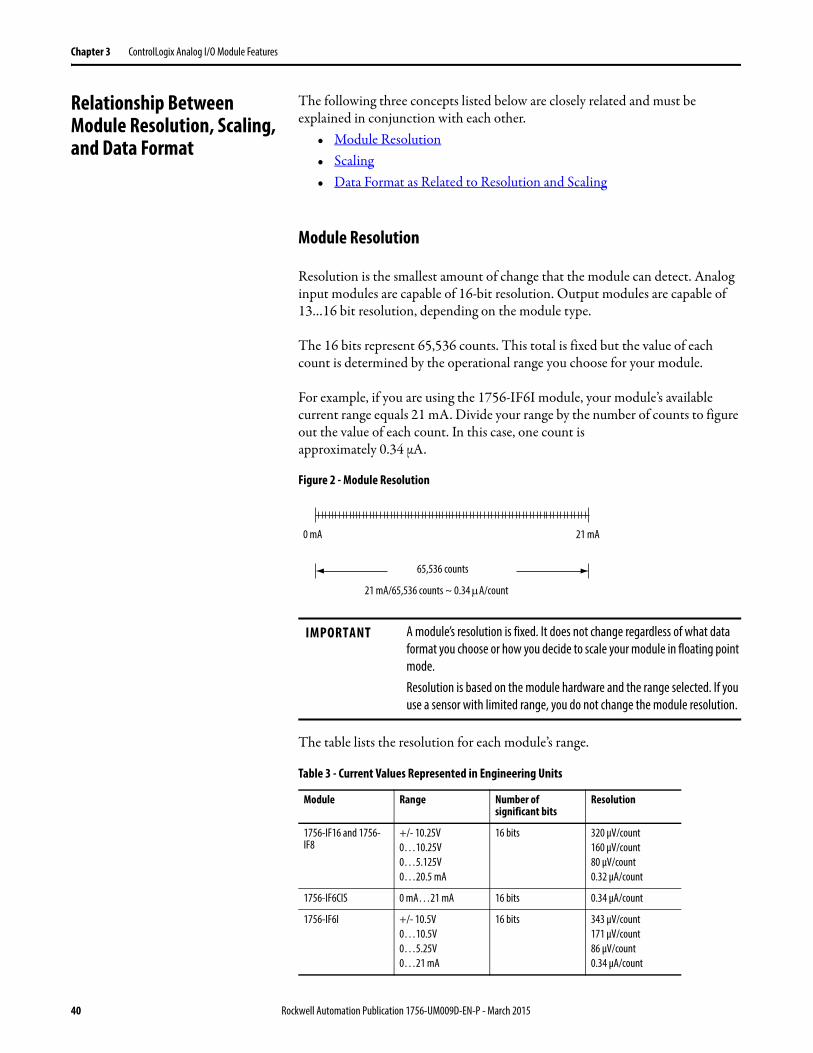
Chapter 3 ControlLogix Analog I/O Module Features
Relationship Between Module Resolution, Scaling, and Data Format
The following three concepts listed below are closely related and must be explained in conjunction with each other.
• Module Resolution• Scaling• Data Format as Related to Resolution and Scaling
Module Resolution
Resolution is the smallest amount of change that the module can detect. Analog input modules are capable of 16-bit resolution. Output modules are capable of 13…16 bit resolution, depending on the module type.
The 16 bits represent 65,536 counts. This total is fixed but the value of each count is determined by the operational range you choose for your module.
For example, if you are using the 1756-IF6I module, your module’s available current range equals 21 mA. Divide your range by the number of counts to figure out the value of each count. In this case, one count isapproximately 0.34 μA.
Figure 2 - Module Resolution
The table lists the resolution for each module’s range.
65,536 counts
0 mA 21 mA
21 mA/65,536 counts ~ 0.34 A/count
IMPORTANT A module’s resolution is fixed. It does not change regardless of what data format you choose or how you decide to scale your module in floating point mode.Resolution is based on the module hardware and the range selected. If you use a sensor with limited range, you do not change the module resolution.
Table 3 - Current Values Represented in Engineering Units
Module Range Number of significant bits
Resolution
1756-IF16 and 1756-IF8
+/- 10.25V0…10.25V0…5.125V0…20.5 mA
16 bits 320 μV/count160 μV/count80 μV/count0.32 μA/count
1756-IF6CIS 0 mA…21 mA 16 bits 0.34 μA/count
1756-IF6I +/- 10.5V0…10.5V0…5.25V0…21 mA
16 bits 343 μV/count171 μV/count86 μV/count0.34 μA/count
40 Rockwell Automation Publication 1756-UM009D-EN-P - March 2015
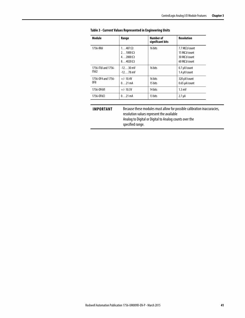
ControlLogix Analog I/O Module Features Chapter 3
1756-IR6I 1…487 2…1000 4…2000 8…4020
16 bits 7.7 M/count15 M/count30 M/count60 M/count
1756-IT6I and 1756-IT6I2
-12…30 mV-12…78 mV
16 bits 0.7 μV/count1.4 μV/count
1756-OF4 and 1756-OF8
+/- 10.4V0…21 mA
16 bits15 bits
320 μV/count0.65 μA/count
1756-OF6VI +/- 10.5V 14 bits 1.3 mV
1756-OF6CI 0…21 mA 13 bits 2.7 μA
IMPORTANT Because these modules must allow for possible calibration inaccuracies, resolution values represent the availableAnalog to Digital or Digital to Analog counts over thespecified range.
Table 3 - Current Values Represented in Engineering Units
Module Range Number of significant bits
Resolution
Rockwell Automation Publication 1756-UM009D-EN-P - March 2015 41
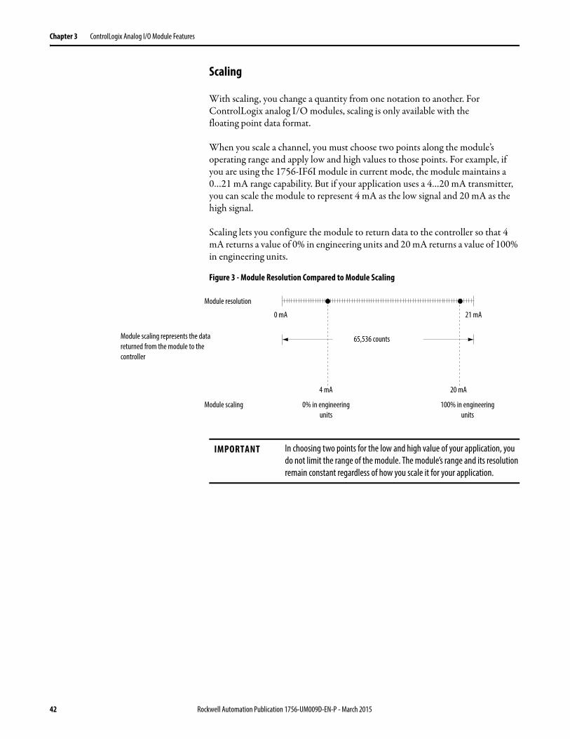
Chapter 3 ControlLogix Analog I/O Module Features
Scaling
With scaling, you change a quantity from one notation to another. For ControlLogix analog I/O modules, scaling is only available with thefloating point data format.
When you scale a channel, you must choose two points along the module’s operating range and apply low and high values to those points. For example, if you are using the 1756-IF6I module in current mode, the module maintains a0…21 mA range capability. But if your application uses a 4…20 mA transmitter, you can scale the module to represent 4 mA as the low signal and 20 mA as the high signal.
Scaling lets you configure the module to return data to the controller so that 4 mA returns a value of 0% in engineering units and 20 mA returns a value of 100% in engineering units.
Figure 3 - Module Resolution Compared to Module Scaling
Module resolution
65,536 counts
0 mA 21 mA
4 mA 20 mA
0% in engineering units
100% in engineering units
Module scaling
Module scaling represents the data returned from the module to the controller
IMPORTANT In choosing two points for the low and high value of your application, you do not limit the range of the module. The module’s range and its resolution remain constant regardless of how you scale it for your application.
42 Rockwell Automation Publication 1756-UM009D-EN-P - March 2015
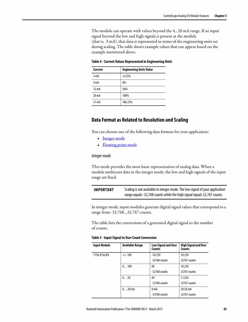
ControlLogix Analog I/O Module Features Chapter 3
The module can operate with values beyond the 4…20 mA range. If an input signal beyond the low and high signals is present at the module(that is, 3 mA), that data is represented in terms of the engineering units set during scaling. The table shows example values that can appear based on the example mentioned above.
Data Format as Related to Resolution and Scaling
You can choose one of the following data formats for your application:• Integer mode• Floating point mode
Integer mode
This mode provides the most basic representation of analog data. When a module multicasts data in the integer mode, the low and high signals of the input range are fixed.
In integer mode, input modules generate digital signal values that correspond to a range from -32,768…32,767 counts.
The table lists the conversions of a generated digital signal to the numberof counts.
Table 4 - Current Values Represented in Engineering Units
Current Engineering Units Value
3 mA -6.25%
4 mA 0%
12 mA 50%
20 mA 100%
21 mA 106.25%
IMPORTANT Scaling is not available in integer mode. The low signal of your application range equals -32,768 counts while the high signal equals 32,767 counts.
Table 5 - Input Signal to User Count Conversion
Input Module Available Range Low Signal and User Counts
High Signal and User Counts
1756-IF16/IF8 +/- 10V -10.25V-32768 counts
10.25V32767 counts
0…10V 0V-32768 counts
10.25V32767 counts
0…5V 0V-32768 counts
5.125V32767 counts
0…20 mA 0 mA-32768 counts
20.58 mA32767 counts
Rockwell Automation Publication 1756-UM009D-EN-P - March 2015 43
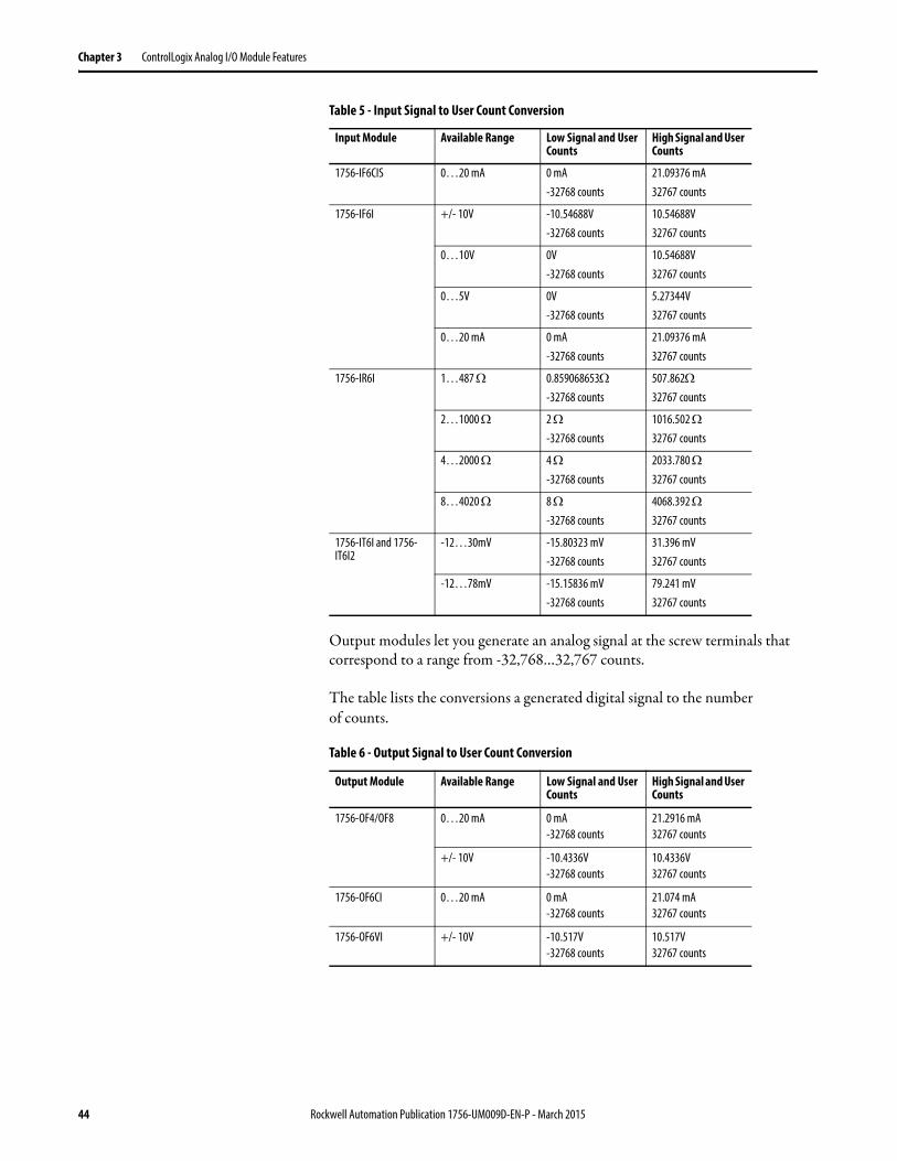
Chapter 3 ControlLogix Analog I/O Module Features
Output modules let you generate an analog signal at the screw terminals that correspond to a range from -32,768…32,767 counts.
The table lists the conversions a generated digital signal to the numberof counts.
1756-IF6CIS 0…20 mA 0 mA-32768 counts
21.09376 mA32767 counts
1756-IF6I +/- 10V -10.54688V-32768 counts
10.54688V32767 counts
0…10V 0V-32768 counts
10.54688V32767 counts
0…5V 0V-32768 counts
5.27344V32767 counts
0…20 mA 0 mA-32768 counts
21.09376 mA32767 counts
1756-IR6I 1…487 0.859068653-32768 counts
507.86232767 counts
2…1000 2 -32768 counts
1016.502 32767 counts
4…2000 4 -32768 counts
2033.780 32767 counts
8…4020 8 -32768 counts
4068.392 32767 counts
1756-IT6I and 1756-IT6I2
-12…30mV -15.80323 mV-32768 counts
31.396 mV32767 counts
-12…78mV -15.15836 mV-32768 counts
79.241 mV32767 counts
Table 6 - Output Signal to User Count Conversion
Output Module Available Range Low Signal and User Counts
High Signal and User Counts
1756-OF4/OF8 0…20 mA 0 mA-32768 counts
21.2916 mA32767 counts
+/- 10V -10.4336V-32768 counts
10.4336V32767 counts
1756-OF6CI 0…20 mA 0 mA-32768 counts
21.074 mA32767 counts
1756-OF6VI +/- 10V -10.517V-32768 counts
10.517V32767 counts
Table 5 - Input Signal to User Count Conversion
Input Module Available Range Low Signal and User Counts
High Signal and User Counts
44 Rockwell Automation Publication 1756-UM009D-EN-P - March 2015
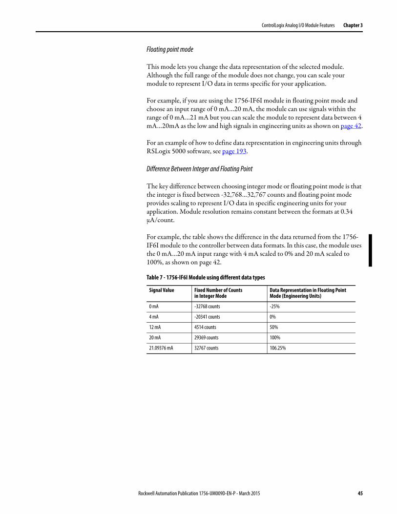
ControlLogix Analog I/O Module Features Chapter 3
Floating point mode
This mode lets you change the data representation of the selected module. Although the full range of the module does not change, you can scale your module to represent I/O data in terms specific for your application.
For example, if you are using the 1756-IF6I module in floating point mode and choose an input range of 0 mA…20 mA, the module can use signals within the range of 0 mA…21 mA but you can scale the module to represent data between 4 mA…20mA as the low and high signals in engineering units as shown on page 42.
For an example of how to define data representation in engineering units through RSLogix 5000 software, see page 193.
Difference Between Integer and Floating Point
The key difference between choosing integer mode or floating point mode is that the integer is fixed between -32,768…32,767 counts and floating point mode provides scaling to represent I/O data in specific engineering units for your application. Module resolution remains constant between the formats at 0.34 μA/count.
For example, the table shows the difference in the data returned from the 1756-IF6I module to the controller between data formats. In this case, the module uses the 0 mA…20 mA input range with 4 mA scaled to 0% and 20 mA scaled to 100%, as shown on page 42.
Table 7 - 1756-IF6I Module using different data types
Signal Value Fixed Number of Countsin Integer Mode
Data Representation in Floating Point Mode (Engineering Units)
0 mA -32768 counts -25%
4 mA -20341 counts 0%
12 mA 4514 counts 50%
20 mA 29369 counts 100%
21.09376 mA 32767 counts 106.25%
Rockwell Automation Publication 1756-UM009D-EN-P - March 2015 45

Chapter 3 ControlLogix Analog I/O Module Features
Notes:
46 Rockwell Automation Publication 1756-UM009D-EN-P - March 2015
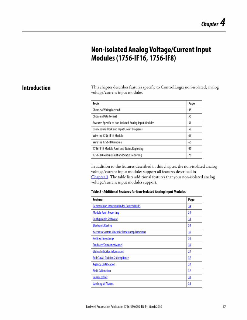
Chapter 4
Non-isolated Analog Voltage/Current Input Modules (1756-IF16, 1756-IF8)
Introduction This chapter describes features specific to ControlLogix non-isolated, analog voltage/current input modules.
In addition to the features described in this chapter, the non-isolated analog voltage/current input modules support all features described inChapter 3. The table lists additional features that your non-isolated analog voltage/current input modules support.
Topic Page
Choose a Wiring Method 48
Choose a Data Format 50
Features Specific to Non-Isolated Analog Input Modules 51
Use Module Block and Input Circuit Diagrams 58
Wire the 1756-IF16 Module 61
Wire the 1756-IF8 Module 65
1756-IF16 Module Fault and Status Reporting 69
1756-IF8 Module Fault and Status Reporting 76
Table 8 - Additional Features for Non-Isolated Analog Input Modules
Feature Page
Removal and Insertion Under Power (RIUP) 34
Module Fault Reporting 34
Configurable Software 34
Electronic Keying 34
Access to System Clock for Timestamp Functions 36
Rolling Timestamp 36
Producer/Consumer Model 36
Status Indicator Information 37
Full Class I Division 2 Compliance 37
Agency Certification 37
Field Calibration 37
Sensor Offset 38
Latching of Alarms 38
Rockwell Automation Publication 1756-UM009D-EN-P - March 2015 47
Chapter 4 Non-isolated Analog Voltage/Current Input Modules (1756-IF16, 1756-IF8)
Choose a Wiring Method The 1756-IF16 and 1756-IF8 modules support these wiring methods:• Single-ended Wiring Method• Differential Wiring Method• High-speed Mode Differential Wiring Method
After determining the wiring method you plan to use on your module, you must inform the system of that choice when you choose a Communication Format. For more information, page 189
For examples of each wiring format on the 1756-IF16 module, see the examples beginning on page 61. For examples of each wiring format on the 1756-IF8 module, see the examples beginning on page 65.
Single-ended Wiring Method
Single-ended wiring compares one side of the signal input to signal ground. This difference is used by the module in generating digital data for the controller.
When using the single-ended wiring method, all input devices are tied to a common ground. In addition to the common ground, the use of single-ended wiring maximizes the number of usable channels on the module(eight channels for the 1756-IF8 module and 16 channels for the 1756-IF16).
48 Rockwell Automation Publication 1756-UM009D-EN-P - March 2015
Non-isolated Analog Voltage/Current Input Modules (1756-IF16, 1756-IF8) Chapter 4
Differential Wiring Method
The differential wiring method is recommended for applications that can have separate signal pairs or a common ground is not available. Differential wiring is recommended for environments where improved noise immunity is needed.
In differential mode, the channels are not totally isolated from each other. If multiple differential input signals have different voltage common references, one channel could affect the reading of another channel. If this condition cannot be avoided, then wire these inputs on different modules or replace the non-isolated module with an isolated input module.
High-speed Mode Differential Wiring Method
You can configure the 1756-IF16 and 1756-IF8 modules for a high-speed mode that gives you the fastest data updates possible. When using the high-speed mode, remember these conditions:
• This mode uses the differential wiring method.• This mode only allows use of one out of every four channels on the
module.
Update times for applications using the high-speed mode can be found on page 52.
IMPORTANT This wiring method lets you use only half a module’s channels. For example, you can use only eight channels on the 1756-IF16 module and four channels on the 1756-IF8 module.
Rockwell Automation Publication 1756-UM009D-EN-P - March 2015 49
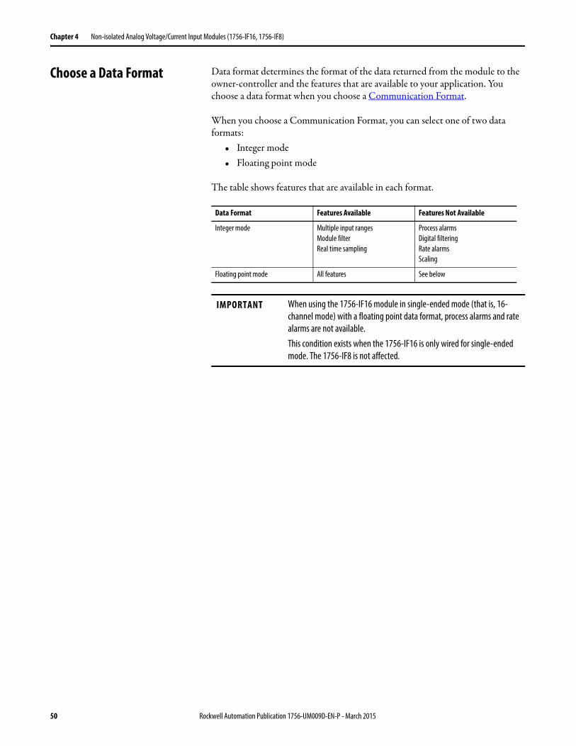
Chapter 4 Non-isolated Analog Voltage/Current Input Modules (1756-IF16, 1756-IF8)
Choose a Data Format Data format determines the format of the data returned from the module to the owner-controller and the features that are available to your application. You choose a data format when you choose a Communication Format.
When you choose a Communication Format, you can select one of two data formats:
• Integer mode• Floating point mode
The table shows features that are available in each format.
Data Format Features Available Features Not Available
Integer mode Multiple input rangesModule filterReal time sampling
Process alarmsDigital filteringRate alarmsScaling
Floating point mode All features See below
IMPORTANT When using the 1756-IF16 module in single-ended mode (that is, 16-channel mode) with a floating point data format, process alarms and rate alarms are not available.This condition exists when the 1756-IF16 is only wired for single-ended mode. The 1756-IF8 is not affected.
50 Rockwell Automation Publication 1756-UM009D-EN-P - March 2015
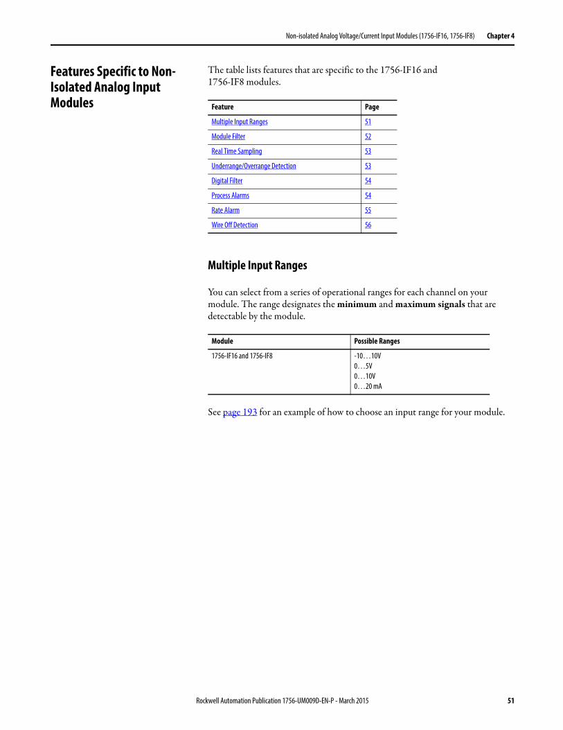
Non-isolated Analog Voltage/Current Input Modules (1756-IF16, 1756-IF8) Chapter 4
Features Specific to Non-Isolated Analog Input Modules
The table lists features that are specific to the 1756-IF16 and1756-IF8 modules.
Multiple Input Ranges
You can select from a series of operational ranges for each channel on your module. The range designates the minimum and maximum signals that are detectable by the module.
See page 193 for an example of how to choose an input range for your module.
Feature Page
Multiple Input Ranges 51
Module Filter 52
Real Time Sampling 53
Underrange/Overrange Detection 53
Digital Filter 54
Process Alarms 54
Rate Alarm 55
Wire Off Detection 56
Module Possible Ranges
1756-IF16 and 1756-IF8 -10…10V0…5V0…10V0…20 mA
Rockwell Automation Publication 1756-UM009D-EN-P - March 2015 51
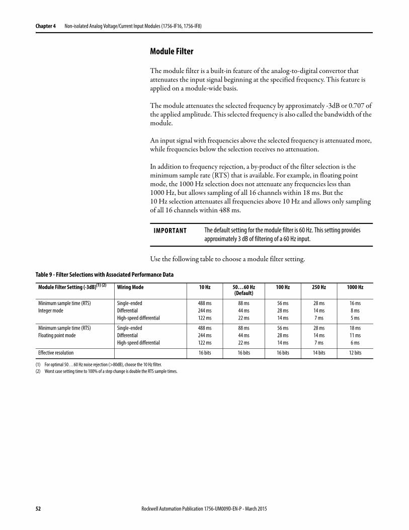
Chapter 4 Non-isolated Analog Voltage/Current Input Modules (1756-IF16, 1756-IF8)
Module Filter
The module filter is a built-in feature of the analog-to-digital convertor that attenuates the input signal beginning at the specified frequency. This feature is applied on a module-wide basis.
The module attenuates the selected frequency by approximately -3dB or 0.707 of the applied amplitude. This selected frequency is also called the bandwidth of the module.
An input signal with frequencies above the selected frequency is attenuated more, while frequencies below the selection receives no attenuation.
In addition to frequency rejection, a by-product of the filter selection is the minimum sample rate (RTS) that is available. For example, in floating point mode, the 1000 Hz selection does not attenuate any frequencies less than1000 Hz, but allows sampling of all 16 channels within 18 ms. But the10 Hz selection attenuates all frequencies above 10 Hz and allows only sampling of all 16 channels within 488 ms.
Use the following table to choose a module filter setting.
IMPORTANT The default setting for the module filter is 60 Hz. This setting provides approximately 3 dB of filtering of a 60 Hz input.
Table 9 - Filter Selections with Associated Performance Data
Module Filter Setting (-3dB)(1) (2) Wiring Mode 10 Hz 50…60 Hz (Default)
100 Hz 250 Hz 1000 Hz
Minimum sample time (RTS)Integer mode
Single-endedDifferentialHigh-speed differential
488 ms244 ms122 ms
88 ms44 ms22 ms
56 ms28 ms14 ms
28 ms14 ms7 ms
16 ms8 ms5 ms
Minimum sample time (RTS)Floating point mode
Single-endedDifferentialHigh-speed differential
488 ms244 ms122 ms
88 ms44 ms22 ms
56 ms28 ms14 ms
28 ms14 ms7 ms
18 ms11 ms6 ms
Effective resolution 16 bits 16 bits 16 bits 14 bits 12 bits
(1) For optimal 50…60 Hz noise rejection (>80dB), choose the 10 Hz filter.(2) Worst case setting time to 100% of a step change is double the RTS sample times.
52 Rockwell Automation Publication 1756-UM009D-EN-P - March 2015
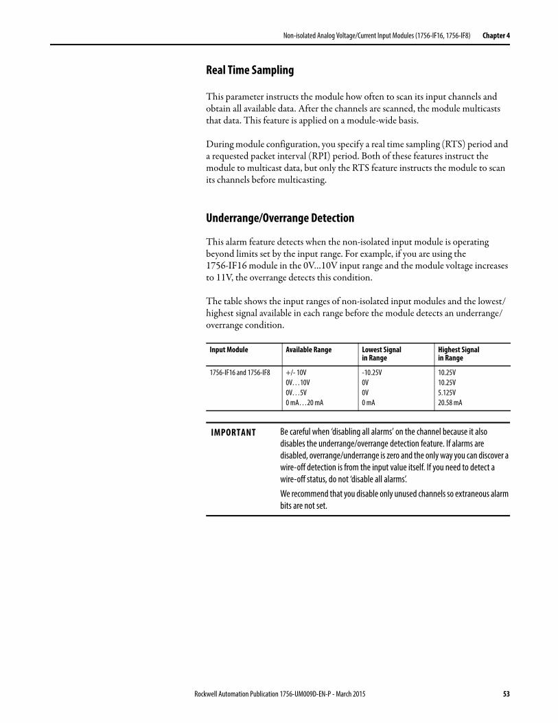
Non-isolated Analog Voltage/Current Input Modules (1756-IF16, 1756-IF8) Chapter 4
Real Time Sampling
This parameter instructs the module how often to scan its input channels and obtain all available data. After the channels are scanned, the module multicasts that data. This feature is applied on a module-wide basis.
During module configuration, you specify a real time sampling (RTS) period and a requested packet interval (RPI) period. Both of these features instruct the module to multicast data, but only the RTS feature instructs the module to scan its channels before multicasting.
Underrange/Overrange Detection
This alarm feature detects when the non-isolated input module is operating beyond limits set by the input range. For example, if you are using the1756-IF16 module in the 0V…10V input range and the module voltage increases to 11V, the overrange detects this condition.
The table shows the input ranges of non-isolated input modules and the lowest/highest signal available in each range before the module detects an underrange/overrange condition.
Input Module Available Range Lowest Signalin Range
Highest Signalin Range
1756-IF16 and 1756-IF8 +/- 10V0V…10V0V…5V0 mA…20 mA
-10.25V0V0V0 mA
10.25V10.25V5.125V20.58 mA
IMPORTANT Be careful when ‘disabling all alarms’ on the channel because it also disables the underrange/overrange detection feature. If alarms are disabled, overrange/underrange is zero and the only way you can discover a wire-off detection is from the input value itself. If you need to detect a wire-off status, do not ‘disable all alarms’.We recommend that you disable only unused channels so extraneous alarm bits are not set.
Rockwell Automation Publication 1756-UM009D-EN-P - March 2015 53
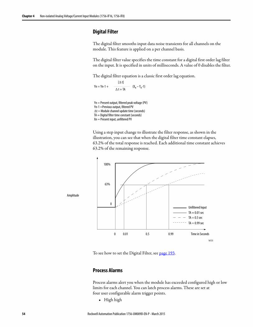
Chapter 4 Non-isolated Analog Voltage/Current Input Modules (1756-IF16, 1756-IF8)
Digital Filter
The digital filter smooths input data noise transients for all channels on the module. This feature is applied on a per channel basis.
The digital filter value specifies the time constant for a digital first order lag filter on the input. It is specified in units of milliseconds. A value of 0 disables the filter.
The digital filter equation is a classic first order lag equation.
Using a step input change to illustrate the filter response, as shown in the illustration, you can see that when the digital filter time constant elapses,63.2% of the total response is reached. Each additional time constant achieves63.2% of the remaining response.
To see how to set the Digital Filter, see page 193.
Process Alarms
Process alarms alert you when the module has exceeded configured high or low limits for each channel. You can latch process alarms. These are set atfour user configurable alarm trigger points.
• High high
Yn = Yn-1 + (Xn – Yn-1)[ t]
t + TA
Yn = Present output, filtered peak voltage (PV)Yn-1 =Previous output, filtered PVt = Module channel update time (seconds)TA = Digital filter time constant (seconds)Xn = Present input, unfiltered PV
0 0.01 0.5 0.99 Time in Seconds
16723
100%
63%
0
Amplitude
Unfiltered InputTA = 0.01 secTA = 0.5 secTA = 0.99 sec
54 Rockwell Automation Publication 1756-UM009D-EN-P - March 2015
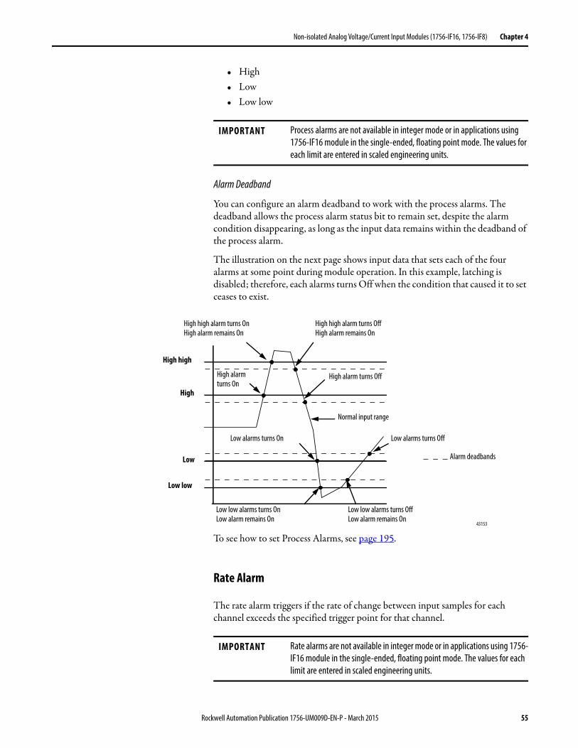
Non-isolated Analog Voltage/Current Input Modules (1756-IF16, 1756-IF8) Chapter 4
• High• Low• Low low
Alarm Deadband
You can configure an alarm deadband to work with the process alarms. The deadband allows the process alarm status bit to remain set, despite the alarm condition disappearing, as long as the input data remains within the deadband of the process alarm.
The illustration on the next page shows input data that sets each of the four alarms at some point during module operation. In this example, latching is disabled; therefore, each alarms turns Off when the condition that caused it to set ceases to exist.
To see how to set Process Alarms, see page 195.
Rate Alarm
The rate alarm triggers if the rate of change between input samples for each channel exceeds the specified trigger point for that channel.
IMPORTANT Process alarms are not available in integer mode or in applications using 1756-IF16 module in the single-ended, floating point mode. The values for each limit are entered in scaled engineering units.
43153
High high
Low low
Low
High
Alarm deadbands
High high alarm turns OffHigh alarm remains On
High high alarm turns OnHigh alarm remains On
Normal input range
Low low alarms turns OffLow alarm remains On
High alarm turns Off
Low low alarms turns OnLow alarm remains On
Low alarms turns OffLow alarms turns On
High alarm turns On
IMPORTANT Rate alarms are not available in integer mode or in applications using 1756-IF16 module in the single-ended, floating point mode. The values for each limit are entered in scaled engineering units.
Rockwell Automation Publication 1756-UM009D-EN-P - March 2015 55
Chapter 4 Non-isolated Analog Voltage/Current Input Modules (1756-IF16, 1756-IF8)
For example, if you set the 1756-IF16 module (with normal scaling in volts) to a rate alarm of 1.0 V/S, the rate alarm only triggers if the difference between measured input samples changes at a rate > 1.0 V/S.
If the module’s RTS is 100 ms that is, sampling new input data every 100 ms) and at time 0, the module measures 5.0 volts and at time 100 ms measures5.08 V, the rate of change is (5.08V - 5.0V) / (100 mS) = 0.8 V/S. The rate alarm does not set as the change is less than the trigger point of 1.0V/s.
If the next sample taken is 4.9V, the rate of change is (4.9V…5.08V)/(100 mS)=-1.8V/S. The absolute value of this result is > 1.0V/S, so the rate alarm sets. Absolute value is applied because rate alarm checks for the magnitude of the rate of change being beyond the trigger point, whether a positive or negative excursion.
Wire Off Detection
The 1756-IF16 and 1756-IF8 modules alert you when a signal wire only has been disconnected from one of its channels or the RTB has been removed from the module. When a wire-off condition occurs for this module, two events occur:
• Input data for that channel changes to a specific scaled value.
• A fault bit is set in the owner-controller that can indicate the presence of a wire-off condition.
Because the 1756-IF16 and 1756-IF8 modules can be applied in voltage or current applications, differences exist as to how a wire-off condition is detected in each application.
IMPORTANT Be careful when ‘disabling all alarms’ on the channel because it also disables the underrange/overrange detection feature. If alarms are disabled, overrange/underrange is zero and the only way you can discover a wire-off detection is from the input value itself. If you need to detect a wire-off status, do not ‘disable all alarms’.We recommend that you disable only unused channels so extraneous alarm bits are not set.
56 Rockwell Automation Publication 1756-UM009D-EN-P - March 2015
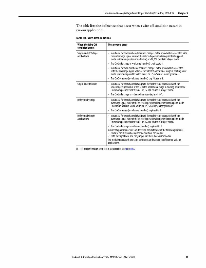
Non-isolated Analog Voltage/Current Input Modules (1756-IF16, 1756-IF8) Chapter 4
The table lists the differences that occur when a wire-off condition occurs in various applications.
Table 10 - Wire-Off Conditions
When the Wire-Off condition occurs
These events occur
Single-ended Voltage Applications
• Input data for odd numbered channels changes to the scaled value associated with the underrange signal value of the selected operational range in floating point mode (minimum possible scaled value) or -32,767 counts in integer mode.
• The ChxUnderrange (x = channel number) tag is set to 1.• Input data for even numbered channels changes to the scaled value associated
with the overrange signal value of the selected operational range in floating point mode (maximum possible scaled value) or 32,767 counts in integer mode.
• The ChxOverrange (x= channel number) tag(1) is set to 1.
(1) For more information about tags in the tag editor, see Appendix A.
Single-Ended Current • Input data for that channel changes to the scaled value associated with the underrange signal value of the selected operational range in floating point mode (minimum possible scaled value) or -32,768 counts in integer mode.
• The ChxUnderrange (x= channel number) tag is set to 1.
Differential Voltage • Input data for that channel changes to the scaled value associated with the overrange signal value of the selected operational range in floating point mode (maximum possible scaled value) or 32,768 counts in integer mode.
• The ChxOverrange (x= channel number) tag is set to 1.
Differential Current Applications
• Input data for that channel changes to the scaled value associated with the overrange signal value of the selected operational range in floating point mode (minimum possible scaled value) or -32,768 counts in integer mode.
• The ChxUnderrange (x=channel number) tag is set to 1.In current applications, wire-off detection occurs for one of the following reasons:• Because the RTB has been disconnected from the module.• Both the signal wire and the jumper wire have been disconnected.The module reacts with the same conditions as described in differential voltage applications.
Rockwell Automation Publication 1756-UM009D-EN-P - March 2015 57
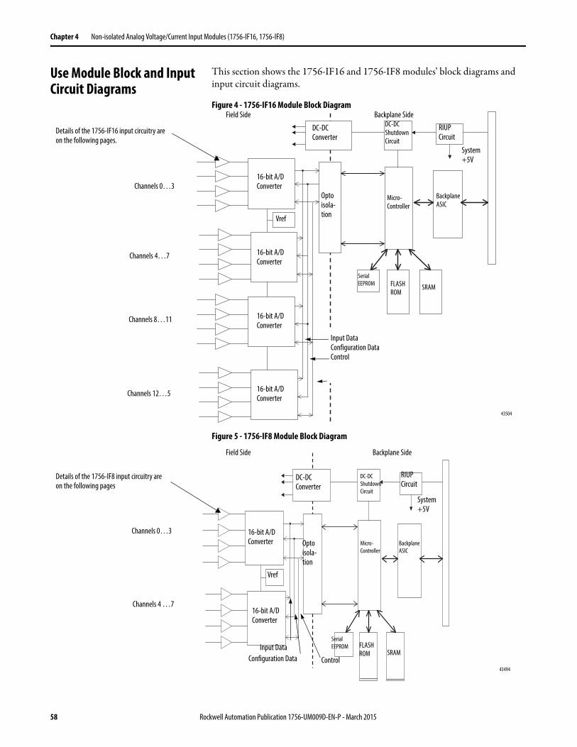
Chapter 4 Non-isolated Analog Voltage/Current Input Modules (1756-IF16, 1756-IF8)
Use Module Block and Input Circuit Diagrams
This section shows the 1756-IF16 and 1756-IF8 modules’ block diagrams and input circuit diagrams.
Figure 4 - 1756-IF16 Module Block Diagram
Figure 5 - 1756-IF8 Module Block Diagram
DC-DC Converter
16-bit A/D Converter
RIUP Circuit
43504
16-bit A/D Converter
16-bit A/D Converter
16-bit A/D Converter
Vref
Opto isola-tion
Micro-Controller
Backplane ASIC
Serial EEPROM FLASH
ROMSRAM
System +5V
Field Side Backplane SideDC-DC Shutdown Circuit
Input DataConfiguration DataControl
Channels 0…3
Channels 4…7
Channels 8…11
Channels 12…5
Details of the 1756-IF16 input circuitry are on the following pages.
DC-DC Converter
16-bit A/D Converter
RIUP Circuit
43494
16-bit A/D Converter
Vref
Opto isola-tion
Serial EEPROM FLASH
ROM SRAM
System +5V
Field Side Backplane Side
DC-DC Shutdown Circuit
Channels 0…3
Channels 4 …7
Details of the 1756-IF8 input circuitry are on the following pages
Micro-Controller
Backplane ASIC
Input DataConfiguration Data Control
58 Rockwell Automation Publication 1756-UM009D-EN-P - March 2015
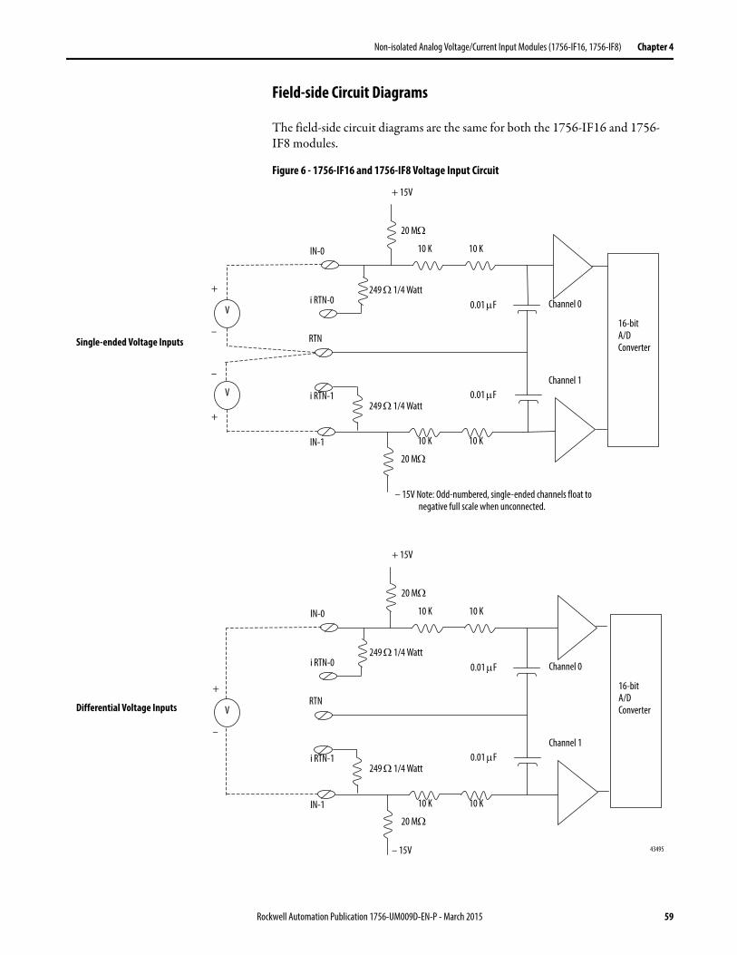
Non-isolated Analog Voltage/Current Input Modules (1756-IF16, 1756-IF8) Chapter 4
Field-side Circuit Diagrams
The field-side circuit diagrams are the same for both the 1756-IF16 and 1756-IF8 modules.
Figure 6 - 1756-IF16 and 1756-IF8 Voltage Input Circuit
43495
Single-ended Voltage Inputs
Differential Voltage Inputs
– 15V Note: Odd-numbered, single-ended channels float to negative full scale when unconnected.
IN-0
i RTN-0
IN-1
i RTN-1
RTN+
–
+ 15V
249 1/4 Watt0.01 F Channel 0
16-bitA/D Converter
– 15V
20 M
249 1/4 Watt
10 K 10 K
0.01 FChannel 1
V
20 M
10 K 10 K
+
–
V
+
–
V
IN-0
i RTN-0
IN-1
i RTN-1
RTN
+ 15V
249 1/4 Watt0.01 F Channel 0
16-bitA/D Converter
20 M
249 1/4 Watt
10 K 10 K
0.01 FChannel 1
20 M
10 K 10 K
Rockwell Automation Publication 1756-UM009D-EN-P - March 2015 59
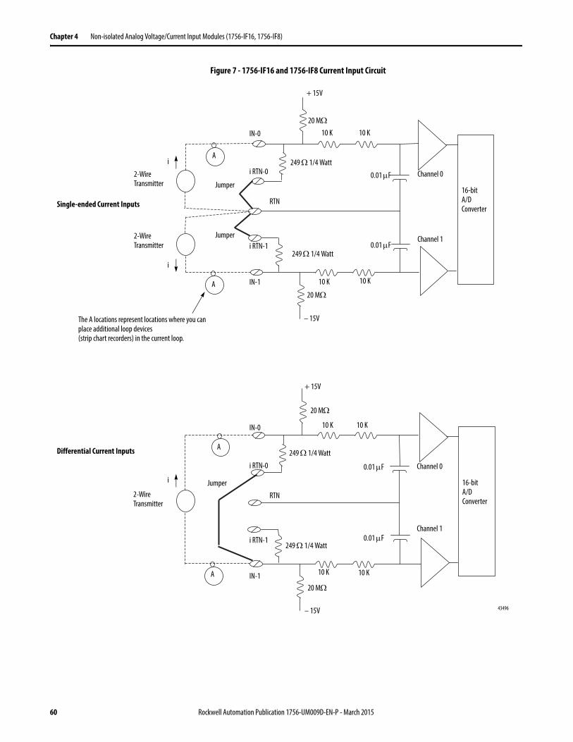
Chapter 4 Non-isolated Analog Voltage/Current Input Modules (1756-IF16, 1756-IF8)
Figure 7 - 1756-IF16 and 1756-IF8 Current Input Circuit
43496
Single-ended Current Inputs
Differential Current Inputs
– 15V
A
A
IN-0
i RTN-0
IN-1
i RTN-1
RTN
+ 15V
249 1/4 Watt
0.01 F Channel 0
16-bitA/D Converter
20 M
249 1/4 Watt
10 K 10 K
0.01 FChannel 1
20 M10 K 10 K
2-Wire Transmitter
2-Wire Transmitter
i
i
– 15V
A
A
IN-0
i RTN-0
IN-1
i RTN-1
RTN
+ 15V
249 1/4 Watt
0.01 F Channel 0
16-bitA/D Converter
20 M
249 1/4 Watt
10 K 10 K
0.01 FChannel 1
20 M
10 K 10 K
2-Wire Transmitter
i Jumper
Jumper
Jumper
The A locations represent locations where you can place additional loop devices(strip chart recorders) in the current loop.
60 Rockwell Automation Publication 1756-UM009D-EN-P - March 2015
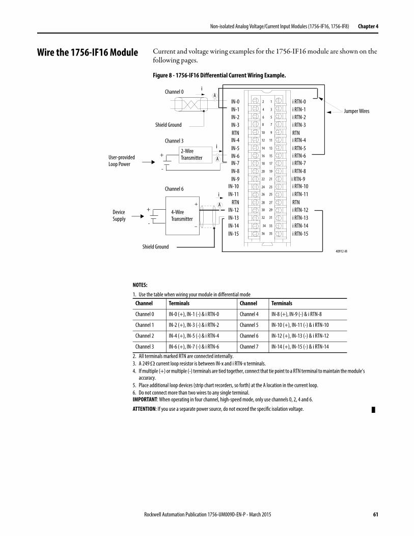
Non-isolated Analog Voltage/Current Input Modules (1756-IF16, 1756-IF8) Chapter 4
Wire the 1756-IF16 Module Current and voltage wiring examples for the 1756-IF16 module are shown on the following pages.
Figure 8 - 1756-IF16 Differential Current Wiring Example.
+
-
+
-
40912-M
1
34
56
78
910
1112
1314
1516
1718
1920
2122
2324
2526
2728
2930
3132
33
3536
IN-0
IN-10
IN-1
IN-9
IN-2
IN-8
IN-5
IN-3
IN-6
RTN
IN-7
IN-4
IN-13IN-12
IN-14
IN-11RTN
i RTN-0
i RTN-7
i RTN-4
i RTN-6
i RTN-8i RTN-9i RTN-10i RTN-11RTNi RTN-12i RTN-13
RTN
i RTN-5
i RTN-1i RTN-2i RTN-3
IN-15i RTN-14i RTN-15
Shield Ground
Channel 0
Channel 3
Jumper Wires
i
iA
NOTES:
1. Use the table when wiring your module in differential mode
2. All terminals marked RTN are connected internally.3. A 249 current loop resistor is between IN-x and i RTN-x terminals.4. If multiple (+) or multiple (-) terminals are tied together, connect that tie point to a RTN terminal to maintain the module’s
accuracy.5. Place additional loop devices (strip chart recorders, so forth) at the A location in the current loop.6. Do not connect more than two wires to any single terminal.IMPORTANT: When operating in four channel, high-speed mode, only use channels 0, 2, 4 and 6.
ATTENTION: If you use a separate power source, do not exceed the specific isolation voltage.
Channel Terminals Channel Terminals
Channel 0 IN-0 (+), IN-1 (-) & i RTN-0 Channel 4 IN-8 (+), IN-9 (-) & i RTN-8
Channel 1 IN-2 (+), IN-3 (-) & i RTN-2 Channel 5 IN-10 (+), IN-11 (-) & i RTN-10
Channel 2 IN-4 (+), IN-5 (-) & i RTN-4 Channel 6 IN-12 (+), IN-13 (-) & i RTN-12
Channel 3 IN-6 (+), IN-7 (-) & i RTN-6 Channel 7 IN-14 (+), IN-15 (-) & i RTN-14
2-Wire Transmitter A
+
–
4-Wire Transmitter
Shield Ground
Channel 6i
A
2
34
User-provided Loop Power
Device Supply
Rockwell Automation Publication 1756-UM009D-EN-P - March 2015 61
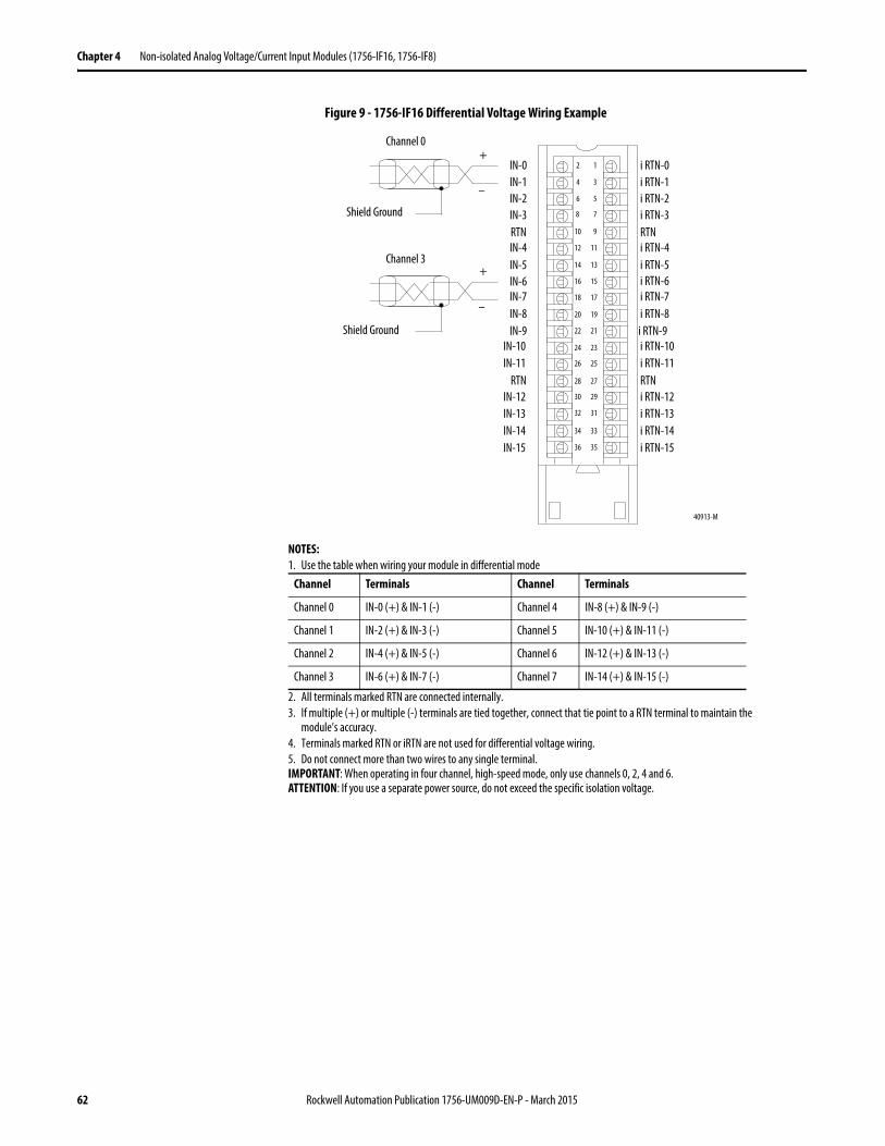
Chapter 4 Non-isolated Analog Voltage/Current Input Modules (1756-IF16, 1756-IF8)
Figure 9 - 1756-IF16 Differential Voltage Wiring Example
40913-M
12
34
56
78
910
1112
1314
1516
1718
1920
2122
2324
2526
2728
2930
3132
3334
3536
IN-0
IN-10
IN-1
IN-9
IN-2
IN-8
IN-5
IN-3
IN-6
RTN
IN-7
IN-4
IN-13IN-12
IN-14
IN-11RTN
i RTN-0
i RTN-7
i RTN-4
i RTN-6
i RTN-8i RTN-9i RTN-10i RTN-11RTNi RTN-12i RTN-13
RTN
i RTN-5
i RTN-1i RTN-2i RTN-3
IN-15i RTN-14i RTN-15
Shield Ground
Shield Ground
Channel 0
Channel 3
+
–
+
–
NOTES:1. Use the table when wiring your module in differential mode
2. All terminals marked RTN are connected internally.3. If multiple (+) or multiple (-) terminals are tied together, connect that tie point to a RTN terminal to maintain the
module’s accuracy.4. Terminals marked RTN or iRTN are not used for differential voltage wiring.5. Do not connect more than two wires to any single terminal.IMPORTANT: When operating in four channel, high-speed mode, only use channels 0, 2, 4 and 6.ATTENTION: If you use a separate power source, do not exceed the specific isolation voltage.
Channel Terminals Channel Terminals
Channel 0 IN-0 (+) & IN-1 (-) Channel 4 IN-8 (+) & IN-9 (-)
Channel 1 IN-2 (+) & IN-3 (-) Channel 5 IN-10 (+) & IN-11 (-)
Channel 2 IN-4 (+) & IN-5 (-) Channel 6 IN-12 (+) & IN-13 (-)
Channel 3 IN-6 (+) & IN-7 (-) Channel 7 IN-14 (+) & IN-15 (-)
62 Rockwell Automation Publication 1756-UM009D-EN-P - March 2015
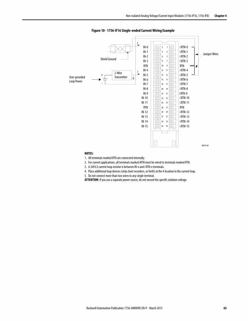
Non-isolated Analog Voltage/Current Input Modules (1756-IF16, 1756-IF8) Chapter 4
Figure 10 - 1756-IF16 Single-ended Current Wiring Example
+
-
12
34
56
78
910
1112
1314
1516
1718
1920
2122
2324
2526
2728
2930
3132
3334
3536
IN-0
IN-10
IN-1
IN-9
IN-2
IN-8
IN-5
IN-3
IN-6
RTN
IN-7
IN-4
IN-13IN-12
IN-14
IN-11RTN
i RTN-0
i RTN-7
i RTN-4
i RTN-6
i RTN-8i RTN-9i RTN-10i RTN-11RTNi RTN-12i RTN-13
RTN
i RTN-5
i RTN-1i RTN-2i RTN-3
IN-15i RTN-14i RTN-15
i
i
A
NOTES:1. All terminals marked RTN are connected internally.2. For current applications, all terminals marked iRTN must be wired to terminals marked RTN.3. A 249 current loop resistor is between IN-x and i RTN-x terminals.4. Place additional loop devices (strip chart recorders, so forth) at the A location in the current loop.5. Do not connect more than two wires to any single terminal.ATTENTION: If you use a separate power source, do not exceed the specific isolation voltage.
40914-M
Jumper Wires
2-Wire Transmitter
Shield Ground
User-provided Loop Power
Rockwell Automation Publication 1756-UM009D-EN-P - March 2015 63
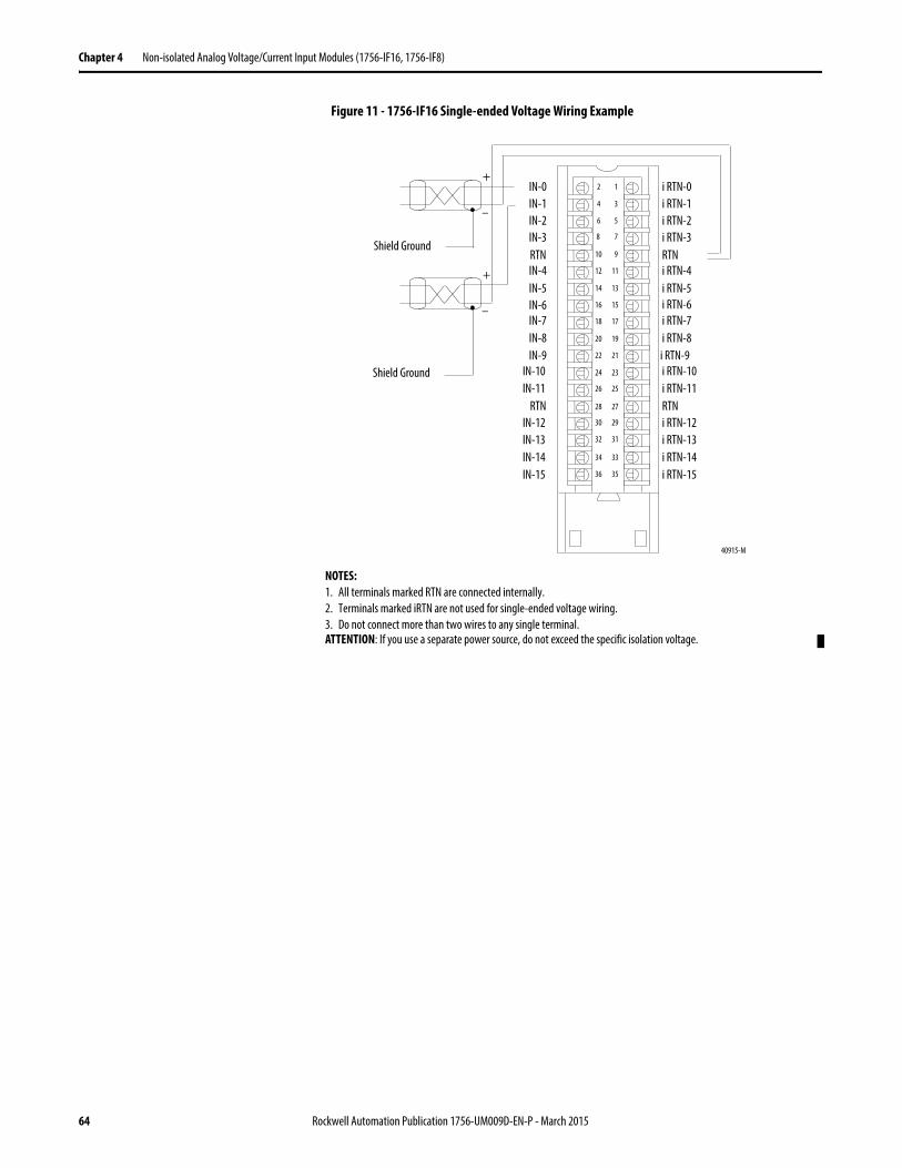
Chapter 4 Non-isolated Analog Voltage/Current Input Modules (1756-IF16, 1756-IF8)
Figure 11 - 1756-IF16 Single-ended Voltage Wiring Example
40915-M
12
34
56
78
910
1112
1314
1516
1718
1920
2122
2324
2526
2728
2930
3132
3334
3536
IN-0
IN-10
IN-1
IN-9
IN-2
IN-8
IN-5
IN-3
IN-6
RTN
IN-7
IN-4
IN-13IN-12
IN-14
IN-11RTN
i RTN-0
i RTN-7
i RTN-4
i RTN-6
i RTN-8i RTN-9i RTN-10i RTN-11RTNi RTN-12i RTN-13
RTN
i RTN-5
i RTN-1i RTN-2i RTN-3
IN-15i RTN-14i RTN-15
Shield Ground
Shield Ground
+
–
+
–
NOTES:1. All terminals marked RTN are connected internally.2. Terminals marked iRTN are not used for single-ended voltage wiring.3. Do not connect more than two wires to any single terminal.ATTENTION: If you use a separate power source, do not exceed the specific isolation voltage.
64 Rockwell Automation Publication 1756-UM009D-EN-P - March 2015
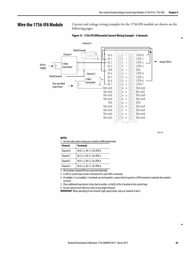
Non-isolated Analog Voltage/Current Input Modules (1756-IF16, 1756-IF8) Chapter 4
Wire the 1756-IF8 Module Current and voltage wiring examples for the 1756-IF8 module are shown on the following pages.
Figure 12 - 1756-IF8 Differential Current Wiring Example - 4 channels.
+
-
+
-
12
34
56
78
910
1112
1314
1516
1718
1920
2122
2324
2526
2728
2930
3132
3334
3536
IN-0
Not used
IN-1
Not used
IN-2
Not used
IN-5
IN-3
IN-6
RTN
IN-7
IN-4
Not usedNot used
Not used
Not usedRTN
i RTN-0
i RTN-7
i RTN-4
i RTN-6
Not usedNot usedNot usedNot usedRTNNot usedNot used
RTN
i RTN-5
i RTN-1i RTN-2i RTN-3
Not usedNot usedNot used
Shield Ground
Channel 0
Channel 1
Jumper Wires
i
i
A
2-Wire Transmitter
A
NOTES:1. Use the table when wiring your module in differential mode
2. All terminals marked RTN are connected internally.3. A 249 current loop resistor is between IN-x and i RTN-x terminals.4. If multiple (+) or multiple (-) terminals are tied together, connect that tie point to a RTN terminal to maintain the module’s
accuracy.5. Place additional loop devices (strip chart recorders, so forth) at the A location in the current loop.6. Do not connect more than two wires to any single terminal.IMPORTANT: When operating in two channel, high-speed mode, only use channels 0 and 2.
Channel Terminals
Channel 0 IN-0 (+), IN-1 (-) & i RTN-0
Channel 1 IN-2 (+), IN-3 (-) & i RTN-2
Channel 2 IN-4 (+), IN-5 (-) & i RTN-4
Channel 3 IN-6 (+), IN-7 (-) & i RTN-6
40912-M
User-provided Loop Power
Channel 3Shield Ground
Device Supply
4-Wire Transmitter
Rockwell Automation Publication 1756-UM009D-EN-P - March 2015 65
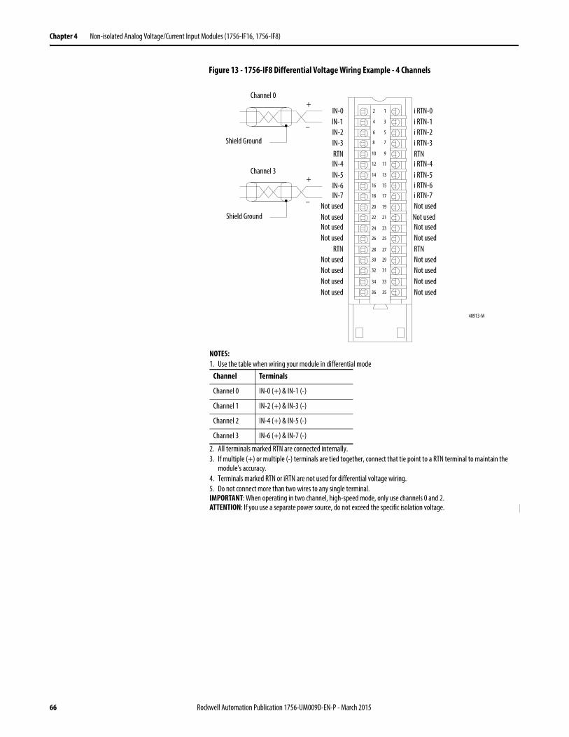
Chapter 4 Non-isolated Analog Voltage/Current Input Modules (1756-IF16, 1756-IF8)
Figure 13 - 1756-IF8 Differential Voltage Wiring Example - 4 Channels
Not usedNot usedNot used
Not usedNot used
Not used
Not usedRTN
Not usedNot usedNot usedNot usedRTNNot usedNot used
Not usedNot usedNot used
12
34
56
78
910
1112
1314
1516
1718
1920
2122
2324
2526
2728
2930
3132
3334
3536
IN-0IN-1IN-2
IN-5
IN-3
IN-6
RTN
IN-7
IN-4
i RTN-0
i RTN-7
i RTN-4
i RTN-6
RTN
i RTN-5
i RTN-1i RTN-2i RTN-3Shield Ground
Shield Ground
Channel 0
Channel 3
+
–
+
–
40913-M
NOTES:1. Use the table when wiring your module in differential mode
2. All terminals marked RTN are connected internally.3. If multiple (+) or multiple (-) terminals are tied together, connect that tie point to a RTN terminal to maintain the
module’s accuracy.4. Terminals marked RTN or iRTN are not used for differential voltage wiring.5. Do not connect more than two wires to any single terminal.IMPORTANT: When operating in two channel, high-speed mode, only use channels 0 and 2.ATTENTION: If you use a separate power source, do not exceed the specific isolation voltage.
Channel Terminals
Channel 0 IN-0 (+) & IN-1 (-)
Channel 1 IN-2 (+) & IN-3 (-)
Channel 2 IN-4 (+) & IN-5 (-)
Channel 3 IN-6 (+) & IN-7 (-)
66 Rockwell Automation Publication 1756-UM009D-EN-P - March 2015
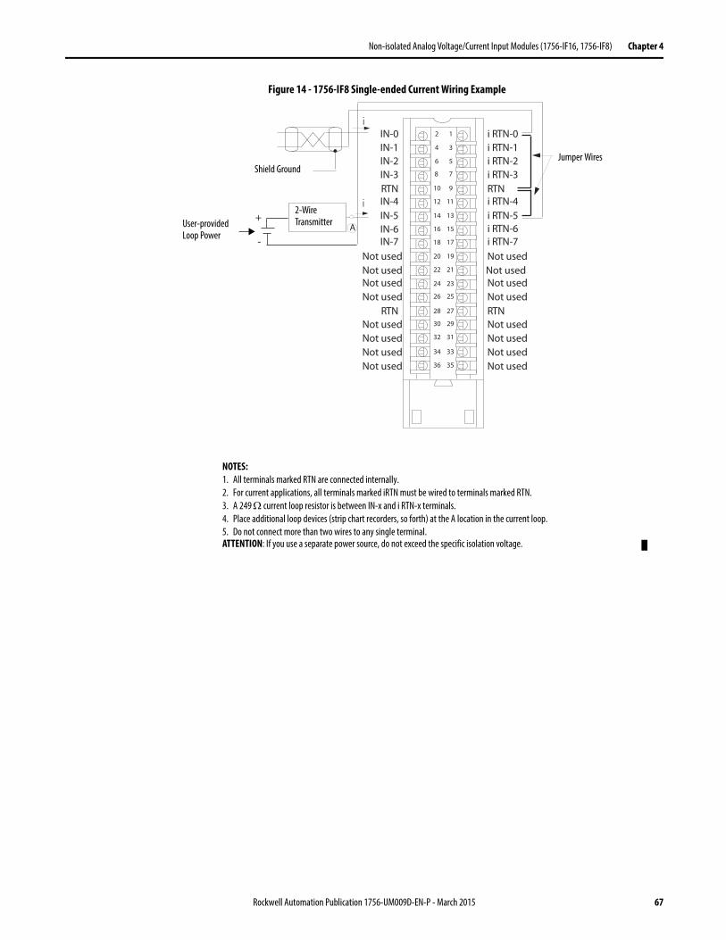
Non-isolated Analog Voltage/Current Input Modules (1756-IF16, 1756-IF8) Chapter 4
Figure 14 - 1756-IF8 Single-ended Current Wiring Example
12
34
56
78
910
1112
1314
1516
1718
1920
2122
2324
2526
2728
2930
3132
3334
3536
IN-0IN-1IN-2
IN-5
IN-3
IN-6
RTN
IN-7
IN-4
i RTN-0
i RTN-7
i RTN-4
i RTN-6
RTN
i RTN-5
i RTN-1i RTN-2i RTN-3
i
i
Not usedNot usedNot used
Not usedNot used
Not used
Not usedRTN
Not usedNot usedNot usedNot usedRTNNot usedNot used
Not usedNot usedNot used
A+
-
2-Wire Transmitter
Shield GroundJumper Wires
NOTES:1. All terminals marked RTN are connected internally.2. For current applications, all terminals marked iRTN must be wired to terminals marked RTN.3. A 249 current loop resistor is between IN-x and i RTN-x terminals.4. Place additional loop devices (strip chart recorders, so forth) at the A location in the current loop.5. Do not connect more than two wires to any single terminal.ATTENTION: If you use a separate power source, do not exceed the specific isolation voltage.
User-provided Loop Power
Rockwell Automation Publication 1756-UM009D-EN-P - March 2015 67
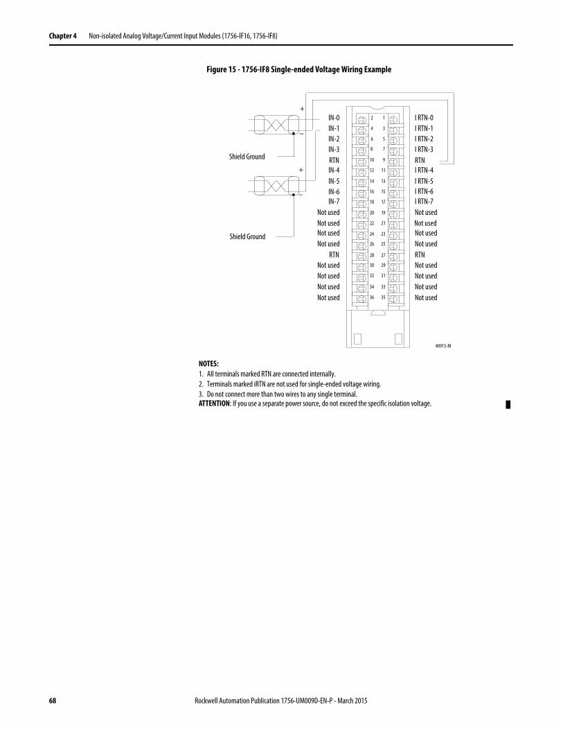
Chapter 4 Non-isolated Analog Voltage/Current Input Modules (1756-IF16, 1756-IF8)
Figure 15 - 1756-IF8 Single-ended Voltage Wiring Example
40915-M
12
34
56
78
910
1112
1314
1516
1718
1920
2122
2324
2526
2728
2930
3132
3334
3536
IN-0
Not used
IN-1
Not used
IN-2
Not used
IN-5
IN-3
IN-6
RTN
IN-7
IN-4
Not usedNot used
Not used
Not usedRTN
I RTN-0
I RTN-7
I RTN-4
I RTN-6
Not usedNot usedNot usedNot usedRTNNot usedNot used
RTN
I RTN-5
I RTN-1I RTN-2I RTN-3
Not usedNot usedNot used
Shield Ground
Shield Ground
+
–
+
–
NOTES:1. All terminals marked RTN are connected internally.2. Terminals marked iRTN are not used for single-ended voltage wiring.3. Do not connect more than two wires to any single terminal.ATTENTION: If you use a separate power source, do not exceed the specific isolation voltage.
68 Rockwell Automation Publication 1756-UM009D-EN-P - March 2015
Non-isolated Analog Voltage/Current Input Modules (1756-IF16, 1756-IF8) Chapter 4
1756-IF16 Module Fault and Status Reporting
The 1756-IF16 module multicasts status and fault data to the owner/listening controller with its channel data. The fault data is arranged in such a manner as to let you choose the level of granularity for examining fault conditions.
Three levels of tags work together to provide an increasing degree of detail as to the specific cause of faults on the module.
The table lists tags that can be examined in ladder logic to indicate when a fault has occurred:
Tag Description
Module Fault Word This word provides fault summary reporting. Its tag name is ModuleFaults.
Channel Fault Word This word provides underrange, overrange and communication fault reporting. Its tag name is ChannelFaults. When examining the Channel Fault Word for faults, remember the following:• 16 channels are used in single-ended wiring.• Eight channels are used in differential wiring.• Four channels are used in high-speed differential wiring.• All bytes start with bit 0.
Channel Status Words These words, one per channel, provide individual channel underrange and overrange fault reporting for process alarms, rate alarms, and calibration faults. Its tag name is ChxStatus.
IMPORTANT Differences exist between floating point and integer modes as they relate to module fault reporting. These differences are explained in the following two sections.
Rockwell Automation Publication 1756-UM009D-EN-P - March 2015 69
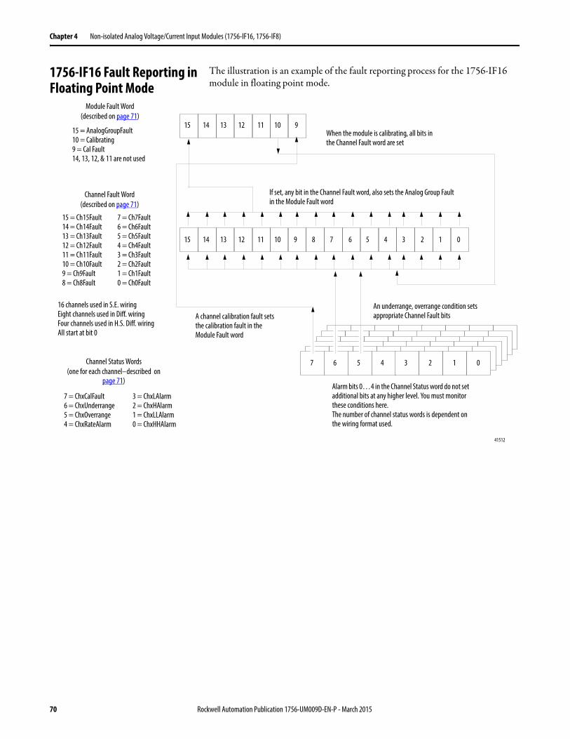
Chapter 4 Non-isolated Analog Voltage/Current Input Modules (1756-IF16, 1756-IF8)
1756-IF16 Fault Reporting in Floating Point Mode
The illustration is an example of the fault reporting process for the 1756-IF16 module in floating point mode.
Module Fault Word(described on page 71)
Channel Fault Word(described on page 71)
Channel Status Words(one for each channel–described on
page 71)
15 14 13 12 11
5 4 3 2 1 0
5 4 3 2 1 07 6
15 = AnalogGroupFault10 = Calibrating9 = Cal Fault14, 13, 12, & 11 are not used
7 = Ch7Fault6 = Ch6Fault5 = Ch5Fault4 = Ch4Fault3 = Ch3Fault2 = Ch2Fault1 = Ch1Fault0 = Ch0Fault
7 = ChxCalFault6 = ChxUnderrange5 = ChxOverrange4 = ChxRateAlarm
If set, any bit in the Channel Fault word, also sets the Analog Group Fault in the Module Fault word
A channel calibration fault sets the calibration fault in the Module Fault word
Alarm bits 0…4 in the Channel Status word do not set additional bits at any higher level. You must monitor these conditions here.The number of channel status words is dependent on the wiring format used.
3 = ChxLAlarm2 = ChxHAlarm1 = ChxLLAlarm0 = ChxHHAlarm
An underrange, overrange condition sets appropriate Channel Fault bits
When the module is calibrating, all bits in the Channel Fault word are set
10 9
9 8 7 615 14 13 12 11 10
15 = Ch15Fault14 = Ch14Fault13 = Ch13Fault12 = Ch12Fault11 = Ch11Fault10 = Ch10Fault9 = Ch9Fault8 = Ch8Fault
16 channels used in S.E. wiringEight channels used in Diff. wiringFour channels used in H.S. Diff. wiringAll start at bit 0
41512
70 Rockwell Automation Publication 1756-UM009D-EN-P - March 2015
Non-isolated Analog Voltage/Current Input Modules (1756-IF16, 1756-IF8) Chapter 4
1756-IF16 Module Fault Word Bits – Floating Point Mode
Bits in this word provide the highest level of fault detection. A non-zero condition in this word reveals that a fault exists on the module. You can examine further down to isolate the fault.
The table lists tags that can be examined in ladder logic to indicate when a fault has occurred.
1756-IF16 Channel Fault Word Bits – Floating Point Mode
During normal module operation, bits in the Channel Fault word are set if any of the respective channels has an Under or Overrange condition. Checking this word for a non-zero value is a quick way to check for Under or Overrange conditions on the module.
The table lists the conditions that set all Channel Fault word bits.
Your logic can monitor the Channel Fault Word bit for a particular input to determine the state of that point.
1756-IF16 Channel Status Word Bits – Floating Point Mode
Any of the Channel Status words, one for each channel, display a non-zero condition if that particular channel has faulted for the conditions listed below. Some of these bits set bits in other Fault words. When the Underrange or Overrange bits (bits 6 and 5) in any of the words are set, the appropriate bit is set in the Channel Fault word.
Tag Description
Analog Group Fault This bit is set when any bits in the Channel Fault word are set. Its tag name is AnalogGroupFault.
Calibrating This bit is set when any channel is being calibrated. When this bit is set, all bits in the Channel Fault word are set. Its tag name is Calibrating.
Calibration Fault This bit is set when any of the individual Channel Calibration Fault bits are set. Its tag name is CalibrationFault.
This condition sets all Channel Fault word bits
And causes the module to display the following in the Channel Fault word bits
A channel is being calibrated • ‘FFFF’ for single-ended operating mode• ‘00FF’ for differential operating mode• ‘000F’ for high-speed differential operating mode
A communication fault occurred between the module and its owner-controller
‘FFFF’ for all bits, regardless of the application
Rockwell Automation Publication 1756-UM009D-EN-P - March 2015 71
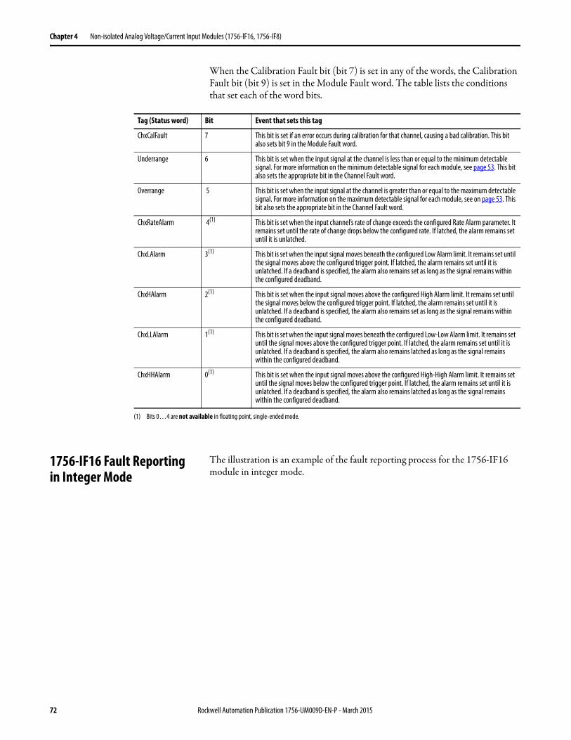
Chapter 4 Non-isolated Analog Voltage/Current Input Modules (1756-IF16, 1756-IF8)
When the Calibration Fault bit (bit 7) is set in any of the words, the Calibration Fault bit (bit 9) is set in the Module Fault word. The table lists the conditions that set each of the word bits.
1756-IF16 Fault Reportingin Integer Mode
The illustration is an example of the fault reporting process for the 1756-IF16 module in integer mode.
Tag (Status word) Bit Event that sets this tag
ChxCalFault 7 This bit is set if an error occurs during calibration for that channel, causing a bad calibration. This bit also sets bit 9 in the Module Fault word.
Underrange 6 This bit is set when the input signal at the channel is less than or equal to the minimum detectable signal. For more information on the minimum detectable signal for each module, see page 53. This bit also sets the appropriate bit in the Channel Fault word.
Overrange 5 This bit is set when the input signal at the channel is greater than or equal to the maximum detectable signal. For more information on the maximum detectable signal for each module, see on page 53. This bit also sets the appropriate bit in the Channel Fault word.
ChxRateAlarm 4(1) This bit is set when the input channel’s rate of change exceeds the configured Rate Alarm parameter. It remains set until the rate of change drops below the configured rate. If latched, the alarm remains set until it is unlatched.
ChxLAlarm 3(1) This bit is set when the input signal moves beneath the configured Low Alarm limit. It remains set until the signal moves above the configured trigger point. If latched, the alarm remains set until it is unlatched. If a deadband is specified, the alarm also remains set as long as the signal remains within the configured deadband.
ChxHAlarm 2(1) This bit is set when the input signal moves above the configured High Alarm limit. It remains set until the signal moves below the configured trigger point. If latched, the alarm remains set until it is unlatched. If a deadband is specified, the alarm also remains set as long as the signal remains within the configured deadband.
ChxLLAlarm 1(1) This bit is set when the input signal moves beneath the configured Low-Low Alarm limit. It remains set until the signal moves above the configured trigger point. If latched, the alarm remains set until it is unlatched. If a deadband is specified, the alarm also remains latched as long as the signal remains within the configured deadband.
ChxHHAlarm 0(1) This bit is set when the input signal moves above the configured High-High Alarm limit. It remains set until the signal moves below the configured trigger point. If latched, the alarm remains set until it is unlatched. If a deadband is specified, the alarm also remains latched as long as the signal remains within the configured deadband.
(1) Bits 0…4 are not available in floating point, single-ended mode.
72 Rockwell Automation Publication 1756-UM009D-EN-P - March 2015
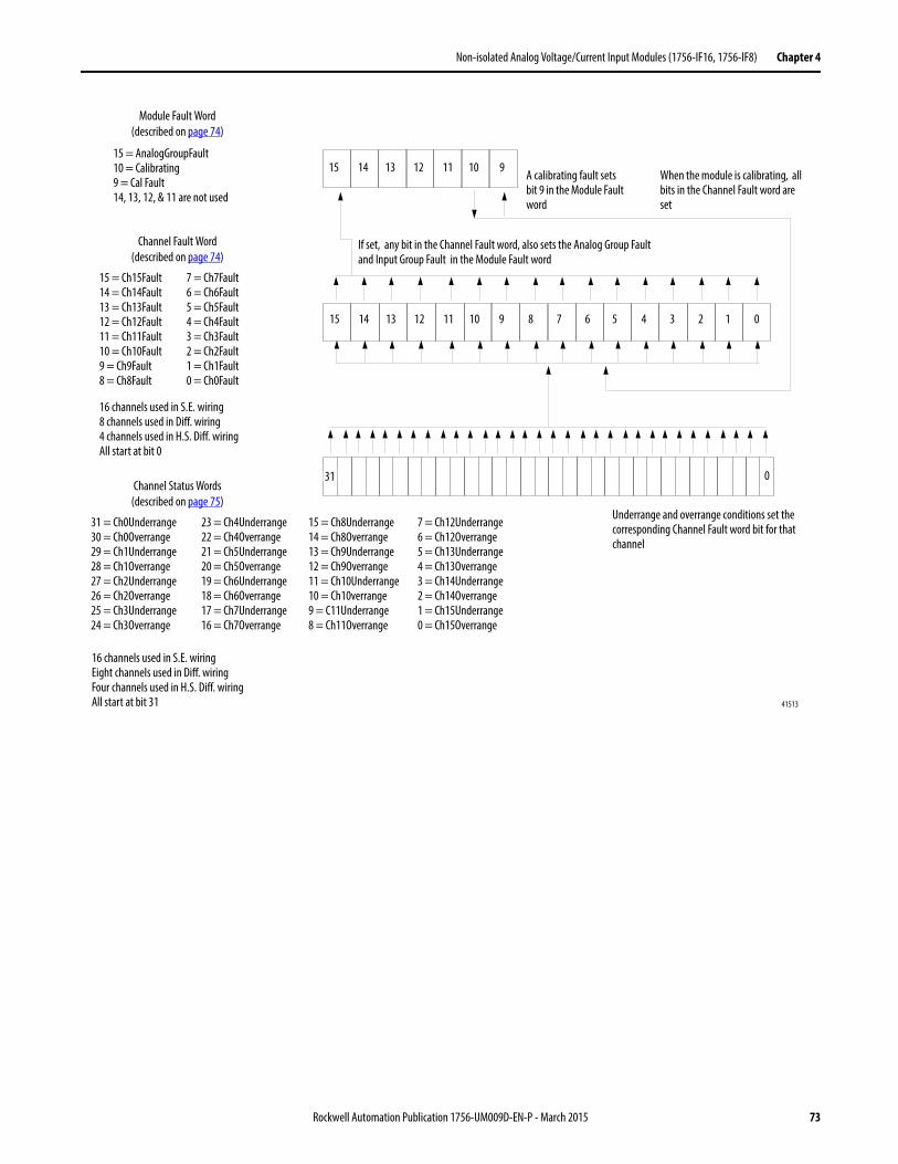
Non-isolated Analog Voltage/Current Input Modules (1756-IF16, 1756-IF8) Chapter 4
Module Fault Word(described on page 74)
15 14 13 12 11 10 9
5 4 3 2 1 0
0
15 = AnalogGroupFault10 = Calibrating9 = Cal Fault14, 13, 12, & 11 are not used
31 = Ch0Underrange30 = Ch0Overrange29 = Ch1Underrange28 = Ch1Overrange27 = Ch2Underrange26 = Ch2Overrange25 = Ch3Underrange24 = Ch3Overrange
41513
Underrange and overrange conditions set the corresponding Channel Fault word bit for that channel
When the module is calibrating, all bits in the Channel Fault word are set
If set, any bit in the Channel Fault word, also sets the Analog Group Fault and Input Group Fault in the Module Fault word
A calibrating fault sets bit 9 in the Module Fault word
31
9 8 7 615 14 13 12 11 10
7 = Ch7Fault6 = Ch6Fault5 = Ch5Fault4 = Ch4Fault3 = Ch3Fault2 = Ch2Fault1 = Ch1Fault0 = Ch0Fault
15 = Ch15Fault14 = Ch14Fault13 = Ch13Fault12 = Ch12Fault11 = Ch11Fault10 = Ch10Fault9 = Ch9Fault8 = Ch8Fault
16 channels used in S.E. wiring8 channels used in Diff. wiring4 channels used in H.S. Diff. wiringAll start at bit 0
23 = Ch4Underrange22 = Ch4Overrange21 = Ch5Underrange20 = Ch5Overrange19 = Ch6Underrange18 = Ch6Overrange17 = Ch7Underrange16 = Ch7Overrange
15 = Ch8Underrange14 = Ch8Overrange13 = Ch9Underrange12 = Ch9Overrange11 = Ch10Underrange10 = Ch10verrange9 = C11Underrange8 = Ch11Overrange
7 = Ch12Underrange6 = Ch12Overrange5 = Ch13Underrange4 = Ch13Overrange3 = Ch14Underrange2 = Ch14Overrange1 = Ch15Underrange0 = Ch15Overrange
16 channels used in S.E. wiringEight channels used in Diff. wiringFour channels used in H.S. Diff. wiringAll start at bit 31
Channel Fault Word(described on page 74)
Channel Status Words(described on page 75)
Rockwell Automation Publication 1756-UM009D-EN-P - March 2015 73
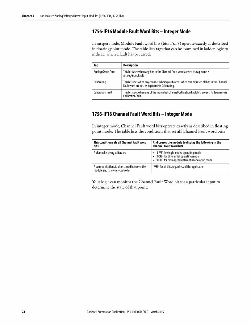
Chapter 4 Non-isolated Analog Voltage/Current Input Modules (1756-IF16, 1756-IF8)
1756-IF16 Module Fault Word Bits – Integer Mode
In integer mode, Module Fault word bits (bits 15…8) operate exactly as described in floating point mode. The table lists tags that can be examined in ladder logic to indicate when a fault has occurred:
1756-IF16 Channel Fault Word Bits – Integer Mode
In integer mode, Channel Fault word bits operate exactly as described in floating point mode. The table lists the conditions that set all Channel Fault word bits:
Your logic can monitor the Channel Fault Word bit for a particular input to determine the state of that point.
Tag Description
Analog Group Fault This bit is set when any bits in the Channel Fault word are set. Its tag name is AnalogGroupFault.
Calibrating This bit is set when any channel is being calibrated. When this bit is set, all bits in the Channel Fault word are set. Its tag name is Calibrating.
Calibration Fault This bit is set when any of the individual Channel Calibration Fault bits are set. Its tag name is CalibrationFault.
This condition sets all Channel Fault word bits
And causes the module to display the following in the Channel Fault word bits
A channel is being calibrated • ‘FFFF’ for single-ended operating mode• ‘00FF’ for differential operating mode• ‘000F’ for high-speed differential operating mode
A communications fault occurred between the module and its owner-controller
‘FFFF’ for all bits, regardless of the application
74 Rockwell Automation Publication 1756-UM009D-EN-P - March 2015
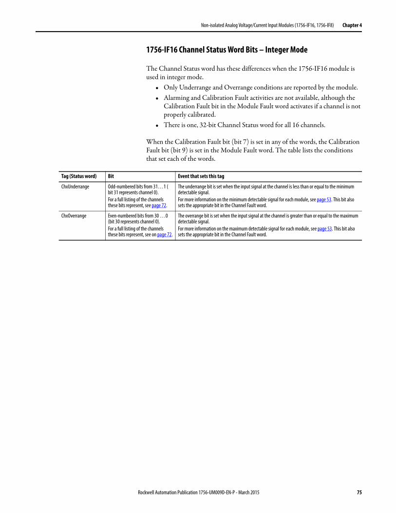
Non-isolated Analog Voltage/Current Input Modules (1756-IF16, 1756-IF8) Chapter 4
1756-IF16 Channel Status Word Bits – Integer Mode
The Channel Status word has these differences when the 1756-IF16 module is used in integer mode.
• Only Underrange and Overrange conditions are reported by the module.• Alarming and Calibration Fault activities are not available, although the
Calibration Fault bit in the Module Fault word activates if a channel is not properly calibrated.
• There is one, 32-bit Channel Status word for all 16 channels.
When the Calibration Fault bit (bit 7) is set in any of the words, the Calibration Fault bit (bit 9) is set in the Module Fault word. The table lists the conditions that set each of the words.
Tag (Status word) Bit Event that sets this tag
ChxUnderrange Odd-numbered bits from 31…1 ( bit 31 represents channel 0).For a full listing of the channels these bits represent, see page 72.
The underrange bit is set when the input signal at the channel is less than or equal to the minimum detectable signal.For more information on the minimum detectable signal for each module, see page 53. This bit also sets the appropriate bit in the Channel Fault word.
ChxOverrange Even-numbered bits from 30 …0 (bit 30 represents channel 0).For a full listing of the channels these bits represent, see on page 72.
The overrange bit is set when the input signal at the channel is greater than or equal to the maximum detectable signal.For more information on the maximum detectable signal for each module, see page 53. This bit also sets the appropriate bit in the Channel Fault word.
Rockwell Automation Publication 1756-UM009D-EN-P - March 2015 75
Chapter 4 Non-isolated Analog Voltage/Current Input Modules (1756-IF16, 1756-IF8)
1756-IF8 Module Fault and Status Reporting
The 1756-IF8 module multicasts status and fault data to the owner/listening controller with its channel data. The fault data is arranged in such a manner as to let you choose the level of granularity for examining fault conditions.
Three levels of tags work together to provide an increasing degree of detail as to the specific cause of faults on the module.
The table lists tags that can be examined in ladder logic to indicate when a fault has occurred:
Tag Description
Module Fault Word This word provides fault summary reporting. Its tag name is ModuleFaults.
Channel Fault Word This word provides underrange, overrange and communication fault reporting. Its tag name is ChannelFaults. When examining the Channel Fault Word for faults, remember the following:• Eight channels are used in single-ended wiring.• Four channels are used in differential wiring.• Two channels are used in high-speed differential wiring.• All bytes start with bit 0.
Channel Status Words These words, one per channel, provide individual channel underrange and overrange fault reporting for process alarms, rate alarms, and calibration faults. Its tag name is ChxStatus.
IMPORTANT Differences exist between floating point and integer modes as they relate to module fault reporting. These differences are explained in the following two sections.
76 Rockwell Automation Publication 1756-UM009D-EN-P - March 2015
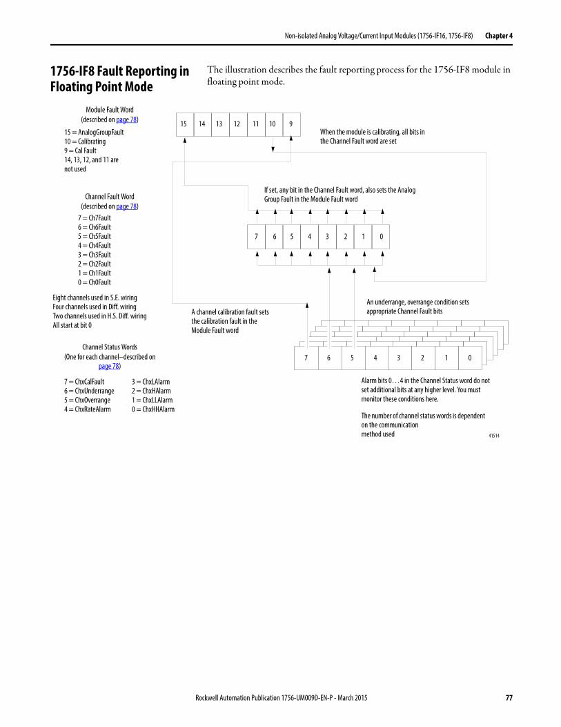
Non-isolated Analog Voltage/Current Input Modules (1756-IF16, 1756-IF8) Chapter 4
1756-IF8 Fault Reporting in Floating Point Mode
The illustration describes the fault reporting process for the 1756-IF8 module in floating point mode.
15 14 13 12 11
5 4 3 2 1 0
5 4 3 2 1 07 6
15 = AnalogGroupFault10 = Calibrating9 = Cal Fault14, 13, 12, and 11 arenot used
7 = Ch7Fault6 = Ch6Fault5 = Ch5Fault4 = Ch4Fault3 = Ch3Fault2 = Ch2Fault1 = Ch1Fault0 = Ch0Fault
7 = ChxCalFault6 = ChxUnderrange5 = ChxOverrange4 = ChxRateAlarm
41514
If set, any bit in the Channel Fault word, also sets the Analog Group Fault in the Module Fault word
A channel calibration fault sets the calibration fault in the Module Fault word
3 = ChxLAlarm2 = ChxHAlarm1 = ChxLLAlarm0 = ChxHHAlarm
An underrange, overrange condition sets appropriate Channel Fault bits
When the module is calibrating, all bits in the Channel Fault word are set
10 9
7 6
Eight channels used in S.E. wiringFour channels used in Diff. wiringTwo channels used in H.S. Diff. wiringAll start at bit 0
Alarm bits 0…4 in the Channel Status word do not set additional bits at any higher level. You must monitor these conditions here.
The number of channel status words is dependent on the communicationmethod used
Module Fault Word(described on page 78)
Channel Fault Word(described on page 78)
Channel Status Words(One for each channel–described on
page 78)
Rockwell Automation Publication 1756-UM009D-EN-P - March 2015 77
Chapter 4 Non-isolated Analog Voltage/Current Input Modules (1756-IF16, 1756-IF8)
1756-IF8 Module Fault Word Bits – Floating Point Mode
Bits in this word provide the highest level of fault detection. A non-zero condition in this word reveals that a fault exists on the module. You can examine further down to isolate the fault.
The table lists tags that can be examined in ladder logic to indicate when a fault has occurred:
1756-IF8 Channel Fault Word Bits – Floating Point Mode
During normal module operation, bits in the Channel Fault word are set if any of the respective channels has an Under or Overrange condition. Checking this word for a non-zero value is a quick way to check for Under or Overrange conditions on the module.
The table lists the conditions that set all Channel Fault word bits:
Your logic can monitor the Channel Fault Word bit for a particular input to determine the state of that point.
1756-IF8 Channel Status Word Bits – Floating Point Mode
Any of the Channel Status words, one for each channel, display a non-zero condition if that particular channel has faulted for the conditions listed below. Some of these bits set bits in other Fault words. When the Underrange and Overrange bits (bits 6…5) in any of the words are set, the appropriate bit is set in the Channel Fault word.
When the Calibration Fault bit (bit 7) is set in any of the words, the Calibration Fault bit (bit 9) is set in the Module Fault word. The table lists the conditions that set each of the word bits.
Tag Description
Analog Group Fault This bit is set when any bits in the Channel Fault word are set. Its tag name is AnalogGroupFault.
Calibrating This bit is set when any channel is being calibrated. When this bit is set, all bits in the Channel Fault word are set. Its tag name is Calibrating.
Calibration Fault This bit is set when any of the individual Channel Calibration Fault bits are set. Its tag name is CalibrationFault.
This condition sets all Channel Fault word bits
And causes the module to display the following in the Channel Fault word bits
A channel is being calibrated • ‘00FF’ for single-ended wiring applications• ‘000F’ for differential wiring applications• ‘0003’ for high speed differential wiring applications
A communication fault occurred between the module and its owner-controller
‘FFFF’ for all bits, regardless of the application
78 Rockwell Automation Publication 1756-UM009D-EN-P - March 2015
Non-isolated Analog Voltage/Current Input Modules (1756-IF16, 1756-IF8) Chapter 4
Tag (Status word) Bit Event that sets this tag
ChxCalFault 7 This bit is set if an error occurs during calibration for that channel, causing a bad calibration. This bit also sets bit 9 in the Module Fault word.
Underrange 6 This bit is set when the input signal at the channel is less than or equal to the minimum detectable signal. For more information on the minimum detectable signal for each module, see page 53. This bit also sets the appropriate bit in the Channel Fault word.
Overrange 5 This bit is set when the input signal at the channel is greater than or equal to the maximum detectable signal. For more information on the maximum detectable signal for each module, see page 53. This bit also sets the appropriate bit in the Channel Fault word.
ChxRateAlarm 4 This bit is set when the input channel’s rate of change exceeds the configured Rate Alarm parameter. It remains set until the rate of change drops below the configured rate. If latched, the alarm remains set until it is unlatched.
ChxLAlarm 3 This bit is set when the input signal moves beneath the configured Low Alarm limit. It remains set until the signal moves above the configured trigger point. If latched, the alarm remains set until it is unlatched. If a deadband is specified, the alarm also remains set as long as the signal remains within the configured deadband.
ChxHAlarm 2 This bit is set when the input signal moves above the configured High Alarm limit. It remains set until the signal moves below the configured trigger point. If latched, the alarm remains set until it is unlatched. If a deadband is specified, the alarm also remains set as long as the signal remains within the configured deadband.
ChxLLAlarm 1 This bit is set when the input signal moves beneath the configured Low-Low Alarm limit. It remains set until the signal moves above the configured trigger point. If latched, the alarm remains set until it is unlatched. If a deadband is specified, the alarm also remains latched as long as the signal remains within the configured deadband.
ChxHHAlarm 0 This bit is set when the input signal moves above the configured High-High Alarm limit. It remains set until the signal moves below the configured trigger point. If latched, the alarm remains set until it is unlatched. If a deadband is specified, the alarm also remains latched as long as the signal remains within the configured deadband.
Rockwell Automation Publication 1756-UM009D-EN-P - March 2015 79
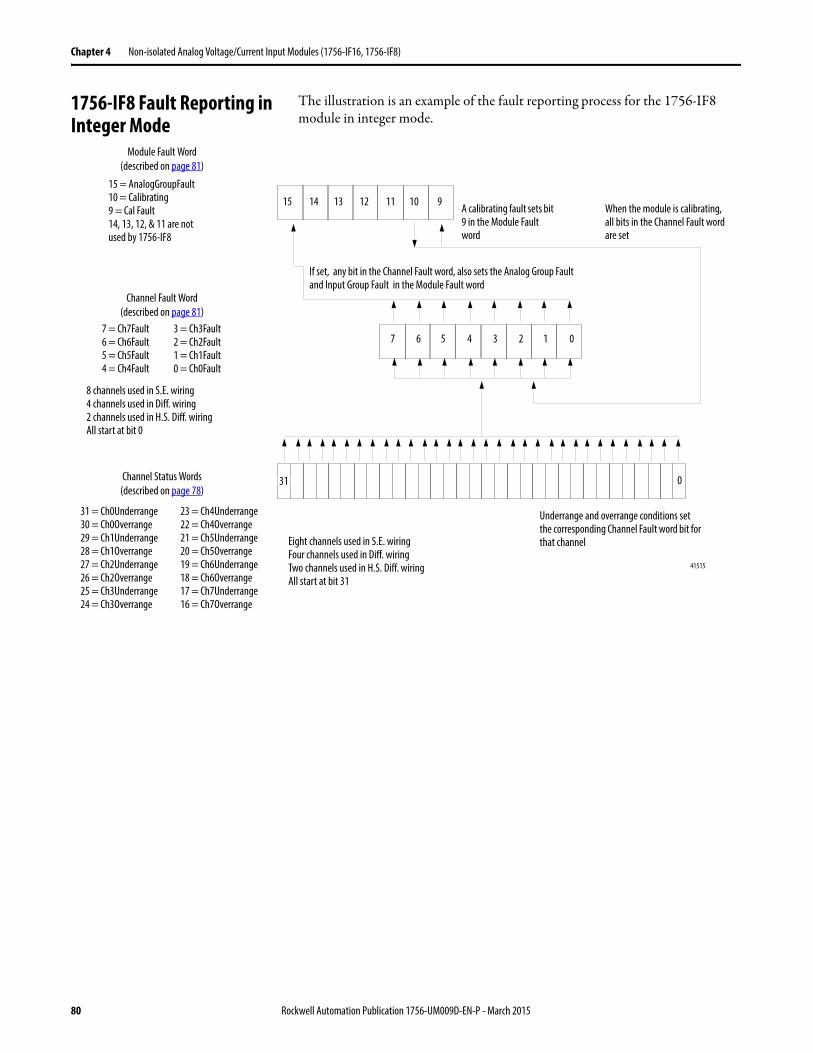
Chapter 4 Non-isolated Analog Voltage/Current Input Modules (1756-IF16, 1756-IF8)
1756-IF8 Fault Reporting in Integer Mode
The illustration is an example of the fault reporting process for the 1756-IF8 module in integer mode.
15 14 13 12 11 10 9
5 4 3 2 1 0
0
15 = AnalogGroupFault10 = Calibrating9 = Cal Fault14, 13, 12, & 11 are notused by 1756-IF8
31 = Ch0Underrange30 = Ch0Overrange29 = Ch1Underrange28 = Ch1Overrange27 = Ch2Underrange26 = Ch2Overrange25 = Ch3Underrange24 = Ch3Overrange
41515
Underrange and overrange conditions set the corresponding Channel Fault word bit for that channel
When the module is calibrating, all bits in the Channel Fault word are set
If set, any bit in the Channel Fault word, also sets the Analog Group Fault and Input Group Fault in the Module Fault word
A calibrating fault sets bit 9 in the Module Fault word
31
7 67 = Ch7Fault6 = Ch6Fault5 = Ch5Fault4 = Ch4Fault
8 channels used in S.E. wiring4 channels used in Diff. wiring2 channels used in H.S. Diff. wiringAll start at bit 0
23 = Ch4Underrange22 = Ch4Overrange21 = Ch5Underrange20 = Ch5Overrange19 = Ch6Underrange18 = Ch6Overrange17 = Ch7Underrange16 = Ch7Overrange
Eight channels used in S.E. wiringFour channels used in Diff. wiringTwo channels used in H.S. Diff. wiringAll start at bit 31
Module Fault Word(described on page 81)
Channel Fault Word(described on page 81)
Channel Status Words(described on page 78)
3 = Ch3Fault2 = Ch2Fault1 = Ch1Fault0 = Ch0Fault
80 Rockwell Automation Publication 1756-UM009D-EN-P - March 2015
Non-isolated Analog Voltage/Current Input Modules (1756-IF16, 1756-IF8) Chapter 4
1756-IF8 Module Fault Word Bits – Integer Mode
In integer mode, Module Fault word bits (bits 15…8) operate exactly as described in floating point mode. The table lists tags that can be examined in ladder logic to indicate when a fault has occurred:
1756-IF8 Channel Fault Word Bits – Integer Mode
In integer mode, Channel Fault word bits operate exactly as described in floating point mode. The table lists the conditions that set all Channel Fault word bits:
Tag Description
Analog Group Fault This bit is set when any bits in the Channel Fault word are set. Its tag name is AnalogGroupFault.
Calibrating This bit is set when any channel is being calibrated. When this bit is set, all bits in the Channel Fault word are set. Its tag name is Calibrating.
Calibration Fault This bit is set when any of the individual Channel Calibration Fault bits are set. Its tag name is CalibrationFault.
This condition sets all Channel Fault word bits
And causes the module to display the following in the Channel Fault word bits
A channel is being calibrated • ‘00FF’ for single-ended wiring applications• ‘000F’ for differential wiring applications• ‘0003’ for high-speed differential wiring applications
A communications fault occurred between the module and its owner-controller
‘FFFF’ for all bits, regardless of the application
Rockwell Automation Publication 1756-UM009D-EN-P - March 2015 81
Chapter 4 Non-isolated Analog Voltage/Current Input Modules (1756-IF16, 1756-IF8)
1756-IF8 Channel Status Word Bits – Integer Mode
The Channel Status word has the following differences when the 1756-IF16 module is used in integer mode:
• Only Underrange and Overrange conditions are reported by the module.• Alarming and Calibration Fault activities are not available, although the
Calibration Fault bit in the Module Fault word activates if a channel is not properly calibrated.
• There is one, 32-bit Channel Status word for all eight channels.
When the Calibration Fault bit (bit 7) is set in any of the words, the Calibration Fault bit (bit 9) is set in the Module Fault word. The table lists the conditions that set each of the words.
Tag (Status word) Bit Event that sets this tag
ChxUnderrange Odd-numbered bits from31…1 ( bit 31 represents channel 17).For a full listing of the channels these bits represent, see on page 78.
The underrange bit is set when the input signal at the channel is less than or equal to the minimum detectable signal.For more information on the minimum detectable signal for each module, see page 53. This bit also sets the appropriate bit in the Channel Fault word.
ChxOverrange Even-numbered bits from30…16 ( bit 30 represents channel 0).For a full listing of the channels these bits represent, see on page 82.
The overrange bit is set when the input signal at the channel is greater than or equal to the maximum detectable signal.For more information on the maximum detectable signal for each module, see page 53. This bit also sets the appropriate bit in the Channel Fault word.
82 Rockwell Automation Publication 1756-UM009D-EN-P - March 2015
Chapter 5
Sourcing Current Loop Input Module (1756-IF6CIS) and Isolated Analog Voltage/Current Input Module (1756-IF6I)
Introduction This chapter describes features specific to the ControlLogix isolated analog voltage/current input module and the ControlLogix sourcing current loop input module.
Topic Page
Use the Isolated Power Source on the 1756-IF6CIS 84
Choose a Data Format 85
Features Specific to the 1756-IF6I and 1756-IF6CIS Modules 85
Use Module Block and Input Circuit Diagrams 93
Wire the 1756-IF6CIS Module 95
Wire the 1756-IF6I Module 98
1756-IF6CIS or 1756-IF6I Module Fault and Status Reporting 100
IMPORTANT The 1756-IF6CIS and 1756-IF6I modules primarily operate the same with a few exceptions, including:•The 1756-IF6CIS only operates in current mode.•The 1756-IF6CIS offers an isolated power source for each channel that
supplies power to external transmitters.The differences on the 1756-IF6CIS module are described on page 84.With a few noted exceptions included in the descriptions, the rest of the features described in this chapter apply toboth modules.
Rockwell Automation Publication 1756-UM009D-EN-P - March 2015 83
Chapter 5 Sourcing Current Loop Input Module (1756-IF6CIS) and Isolated Analog Voltage/Current Input Module (1756-IF6I)
Use the Isolated Power Source on the 1756-IF6CIS
The 1756-IF6CIS module offers an internal power source on each channel. The source is current limited to 28 mA and allows the module to power a two-wire transmitter directly without the need for an external power supply. The transmitter can then vary the current to the analog input in proportion to the process variable being measured. The inclusion of an internal on-board current source saves you the expense of extra power supplies and greatly simplifies the interface wiring to field devices.
In addition to supplying loop power to two-wire transmitters, the module can also accommodate current loops powered by an external supply and loops using four-wire transmitters.
Power Calculations with the 1756-IF6CIS Module
The 1756-IF6CIS module uses the system power supply (1756-Px7x) as the source for loop power. Because of the demands placed on that supply (that is, the 1756-IF6CIS module consumes 7.9 W of backplane power), special care must be taken when calculating the power requirements for modules in the same chassis as a 1756-IF6CIS module.
For example, when used with the 1756-L55M13 controller, you can place only eight 1756-IF6CIS modules in the chassis before exceeding the wattage capacity of the power supply.
Other Devices in the Wiring Loop
The voltage source on each channel can drive loop impedance of up to1000 ohms. This lets you include other devices, such as chart recorders and meters, in the current loop.
For more information on wiring the 1756-IF6CIS module, see page 95.
84 Rockwell Automation Publication 1756-UM009D-EN-P - March 2015
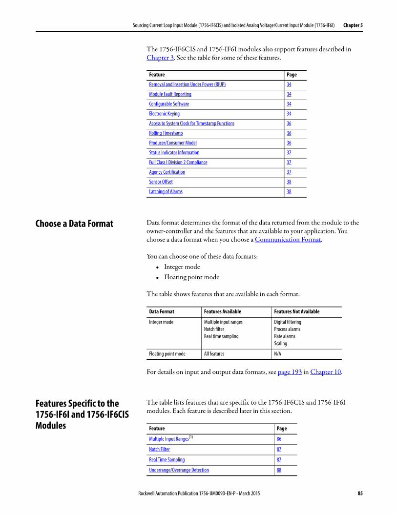
Sourcing Current Loop Input Module (1756-IF6CIS) and Isolated Analog Voltage/Current Input Module (1756-IF6I) Chapter 5
The 1756-IF6CIS and 1756-IF6I modules also support features described in Chapter 3. See the table for some of these features.
Choose a Data Format Data format determines the format of the data returned from the module to the owner-controller and the features that are available to your application. You choose a data format when you choose a Communication Format.
You can choose one of these data formats:• Integer mode• Floating point mode
The table shows features that are available in each format.
For details on input and output data formats, see page 193 in Chapter 10.
Features Specific to the 1756-IF6I and 1756-IF6CIS Modules
The table lists features that are specific to the 1756-IF6CIS and 1756-IF6I modules. Each feature is described later in this section.
Feature Page
Removal and Insertion Under Power (RIUP) 34
Module Fault Reporting 34
Configurable Software 34
Electronic Keying 34
Access to System Clock for Timestamp Functions 36
Rolling Timestamp 36
Producer/Consumer Model 36
Status Indicator Information 37
Full Class I Division 2 Compliance 37
Agency Certification 37
Sensor Offset 38
Latching of Alarms 38
Data Format Features Available Features Not Available
Integer mode Multiple input rangesNotch filterReal time sampling
Digital filteringProcess alarmsRate alarmsScaling
Floating point mode All features N/A
Feature Page
Multiple Input Ranges(1) 86
Notch Filter 87
Real Time Sampling 87
Underrange/Overrange Detection 88
Rockwell Automation Publication 1756-UM009D-EN-P - March 2015 85
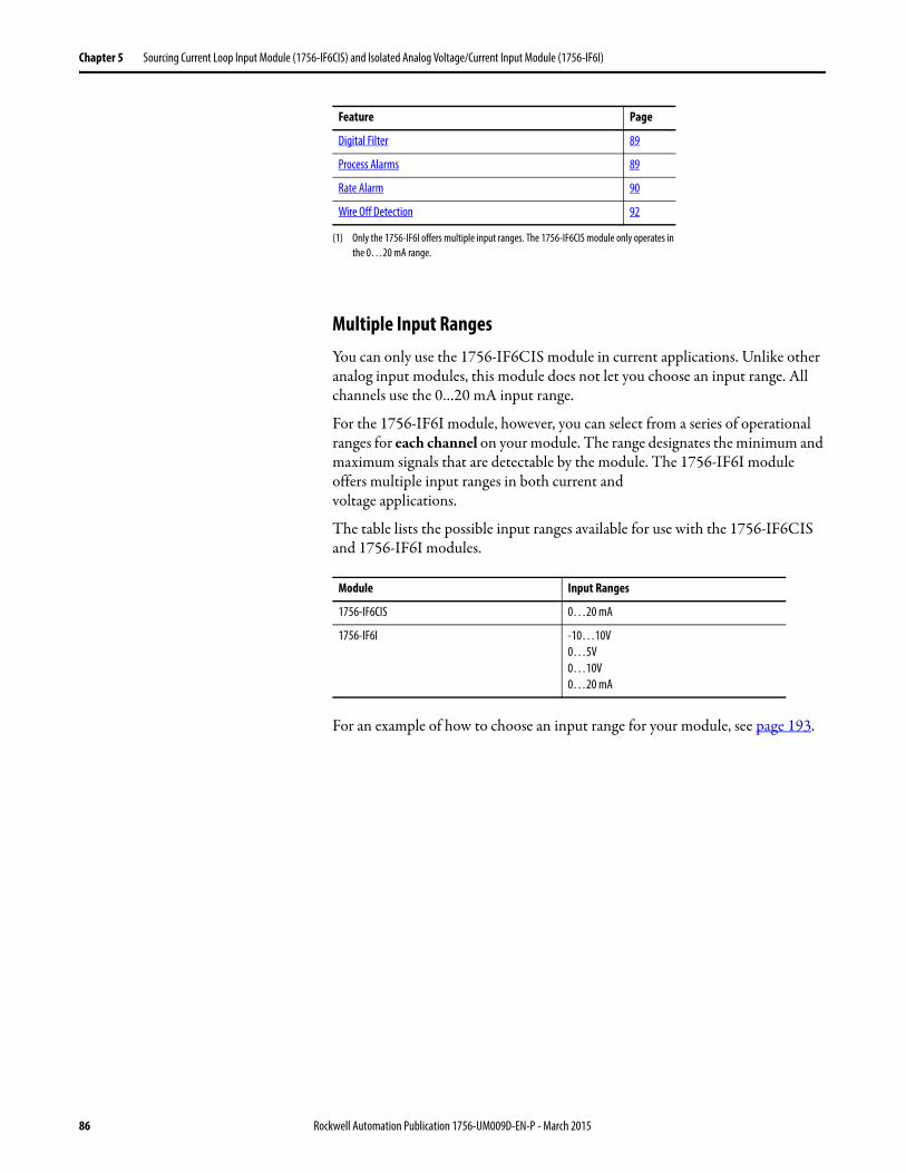
Chapter 5 Sourcing Current Loop Input Module (1756-IF6CIS) and Isolated Analog Voltage/Current Input Module (1756-IF6I)
Multiple Input RangesYou can only use the 1756-IF6CIS module in current applications. Unlike other analog input modules, this module does not let you choose an input range. All channels use the 0…20 mA input range.
For the 1756-IF6I module, however, you can select from a series of operational ranges for each channel on your module. The range designates the minimum and maximum signals that are detectable by the module. The 1756-IF6I module offers multiple input ranges in both current andvoltage applications.
The table lists the possible input ranges available for use with the 1756-IF6CIS and 1756-IF6I modules.
For an example of how to choose an input range for your module, see page 193.
Digital Filter 89
Process Alarms 89
Rate Alarm 90
Wire Off Detection 92
(1) Only the 1756-IF6I offers multiple input ranges. The 1756-IF6CIS module only operates in the 0…20 mA range.
Module Input Ranges
1756-IF6CIS 0…20 mA
1756-IF6I -10…10V0…5V0…10V0…20 mA
Feature Page
86 Rockwell Automation Publication 1756-UM009D-EN-P - March 2015
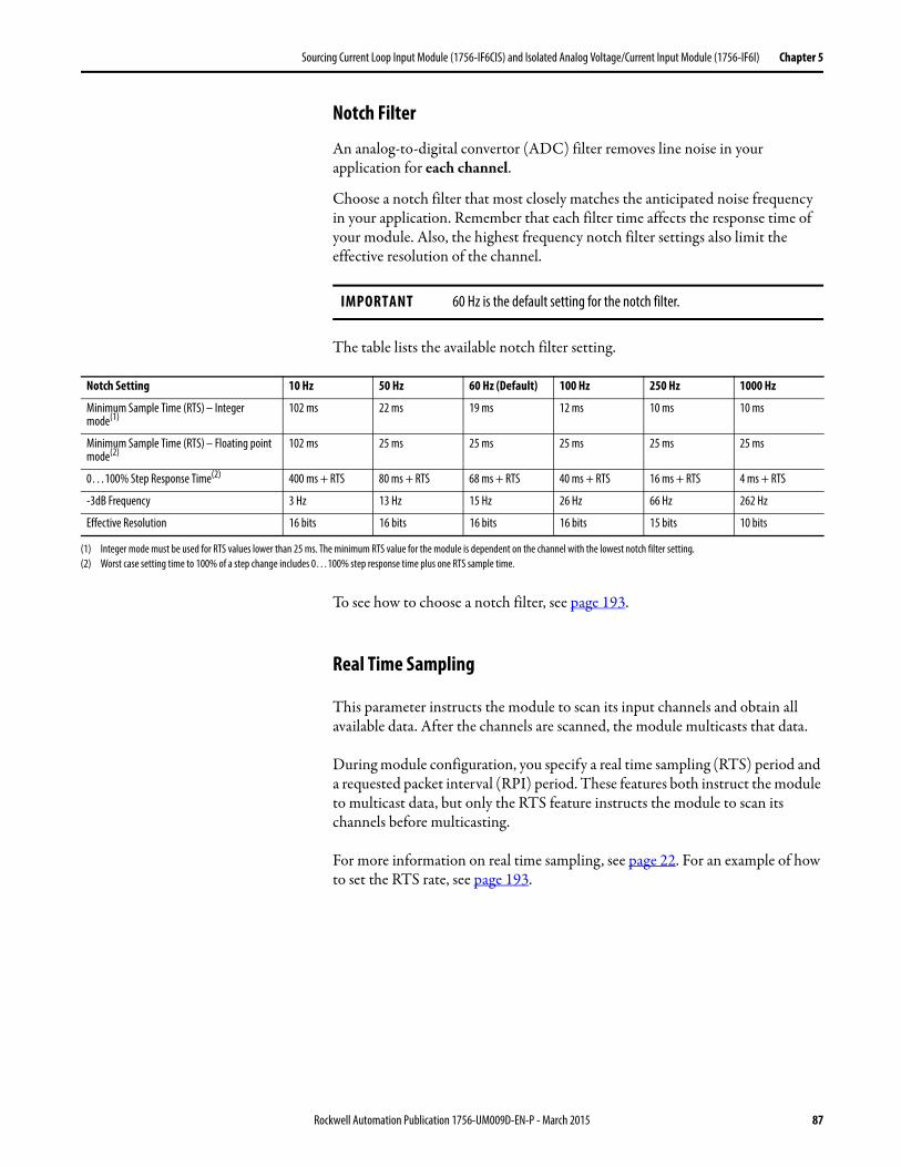
Sourcing Current Loop Input Module (1756-IF6CIS) and Isolated Analog Voltage/Current Input Module (1756-IF6I) Chapter 5
Notch Filter
An analog-to-digital convertor (ADC) filter removes line noise in your application for each channel.
Choose a notch filter that most closely matches the anticipated noise frequency in your application. Remember that each filter time affects the response time of your module. Also, the highest frequency notch filter settings also limit the effective resolution of the channel.
The table lists the available notch filter setting.
To see how to choose a notch filter, see page 193.
Real Time Sampling
This parameter instructs the module to scan its input channels and obtain all available data. After the channels are scanned, the module multicasts that data.
During module configuration, you specify a real time sampling (RTS) period and a requested packet interval (RPI) period. These features both instruct the module to multicast data, but only the RTS feature instructs the module to scan its channels before multicasting.
For more information on real time sampling, see page 22. For an example of how to set the RTS rate, see page 193.
IMPORTANT 60 Hz is the default setting for the notch filter.
Notch Setting 10 Hz 50 Hz 60 Hz (Default) 100 Hz 250 Hz 1000 Hz
Minimum Sample Time (RTS) – Integer mode(1)
102 ms 22 ms 19 ms 12 ms 10 ms 10 ms
Minimum Sample Time (RTS) – Floating point mode(2)
102 ms 25 ms 25 ms 25 ms 25 ms 25 ms
0…100% Step Response Time(2) 400 ms + RTS 80 ms + RTS 68 ms + RTS 40 ms + RTS 16 ms + RTS 4 ms + RTS
-3dB Frequency 3 Hz 13 Hz 15 Hz 26 Hz 66 Hz 262 Hz
Effective Resolution 16 bits 16 bits 16 bits 16 bits 15 bits 10 bits
(1) Integer mode must be used for RTS values lower than 25 ms. The minimum RTS value for the module is dependent on the channel with the lowest notch filter setting.(2) Worst case setting time to 100% of a step change includes 0…100% step response time plus one RTS sample time.
Rockwell Automation Publication 1756-UM009D-EN-P - March 2015 87
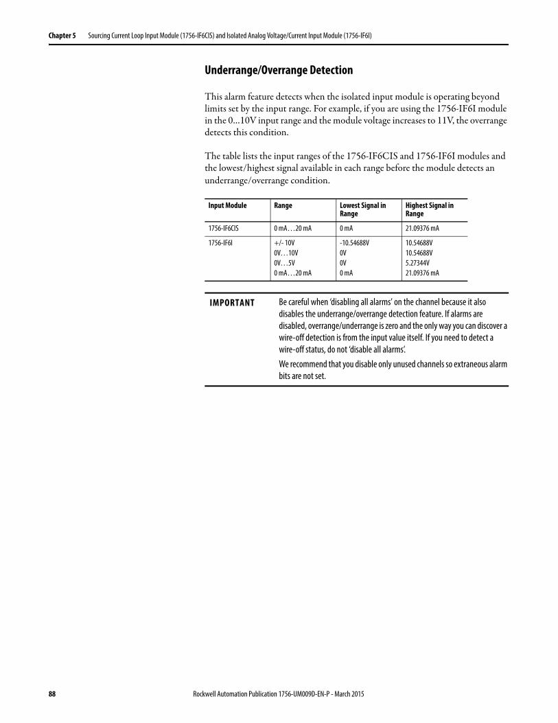
Chapter 5 Sourcing Current Loop Input Module (1756-IF6CIS) and Isolated Analog Voltage/Current Input Module (1756-IF6I)
Underrange/Overrange Detection
This alarm feature detects when the isolated input module is operating beyond limits set by the input range. For example, if you are using the 1756-IF6I module in the 0…10V input range and the module voltage increases to 11V, the overrange detects this condition.
The table lists the input ranges of the 1756-IF6CIS and 1756-IF6I modules and the lowest/highest signal available in each range before the module detects an underrange/overrange condition.
Input Module Range Lowest Signal in Range
Highest Signal in Range
1756-IF6CIS 0 mA…20 mA 0 mA 21.09376 mA
1756-IF6I +/- 10V0V…10V0V…5V0 mA…20 mA
-10.54688V0V0V0 mA
10.54688V10.54688V5.27344V21.09376 mA
IMPORTANT Be careful when ‘disabling all alarms’ on the channel because it also disables the underrange/overrange detection feature. If alarms are disabled, overrange/underrange is zero and the only way you can discover a wire-off detection is from the input value itself. If you need to detect a wire-off status, do not ‘disable all alarms’.We recommend that you disable only unused channels so extraneous alarm bits are not set.
88 Rockwell Automation Publication 1756-UM009D-EN-P - March 2015
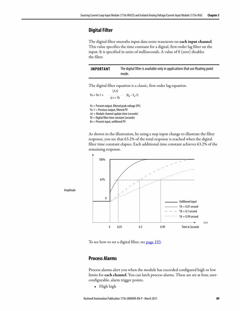
Sourcing Current Loop Input Module (1756-IF6CIS) and Isolated Analog Voltage/Current Input Module (1756-IF6I) Chapter 5
Digital Filter
The digital filter smooths input data noise transients on each input channel. This value specifies the time constant for a digital, first-order lag filter on the input. It is specified in units of milliseconds. A value of 0 (zero) disablesthe filter.
The digital filter equation is a classic, first order lag equation.
As shown in the illustration, by using a step input change to illustrate the filter response, you see that 63.2% of the total response is reached when the digital filter time constant elapses. Each additional time constant achieves 63.2% of the remaining response.
To see how to set a digital filter, see page 193.
Process Alarms
Process alarms alert you when the module has exceeded configured high or low limits for each channel. You can latch process alarms. These are set at four, user-configurable, alarm trigger points.
• High high
IMPORTANT The digital filter is available only in applications that use floating point mode.
Yn = Yn-1 + (Xn – Yn-1)[ t]
t + TA
Yn = Present output, filtered peak voltage (PV)Yn-1 = Previous output, filtered PVt = Module channel update time (seconds)TA = Digital filter time constant (seconds)Xn = Present input, unfiltered PV
0 0.01 0.5 0.99 Time in Seconds16723
100%
63%
0
Amplitude
Unfiltered inputTA = 0.01 secondTA = 0.5 second
TA = 0.99 second
Rockwell Automation Publication 1756-UM009D-EN-P - March 2015 89
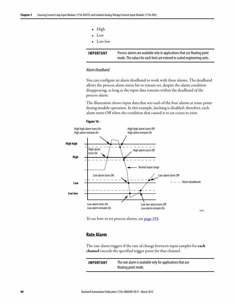
Chapter 5 Sourcing Current Loop Input Module (1756-IF6CIS) and Isolated Analog Voltage/Current Input Module (1756-IF6I)
• High• Low• Low low
Alarm Deadband
You can configure an alarm deadband to work with these alarms. The deadband allows the process alarm status bit to remain set, despite the alarm condition disappearing, as long as the input data remains within the deadband of the process alarm.
The illustration shows input data that sets each of the four alarms at some point during module operation. In this example, latching is disabled; therefore, each alarm turns Off when the condition that caused it to set ceases to exist.
Figure 16 -
To see how to set process alarms, see page 195.
Rate Alarm
The rate alarm triggers if the rate of change between input samples for each channel exceeds the specified trigger point for that channel.
IMPORTANT Process alarms are available only in applications that use floating point mode. The values for each limit are entered in scaled engineering units.
43153
High high
Low low
Low
High
Alarm deadbands
High high alarm turns OffHigh alarm remains On
High high alarm turns OnHigh alarm remains On
Normal input range
Low low alarm turns OffLow alarm remains On
High alarm turns Off
Low alarm turns OnLow alarm remains On
Low alarm turns OffLow alarm turns ON
High alarm turns On
IMPORTANT The rate alarm is available only for applications that usefloating point mode.
90 Rockwell Automation Publication 1756-UM009D-EN-P - March 2015
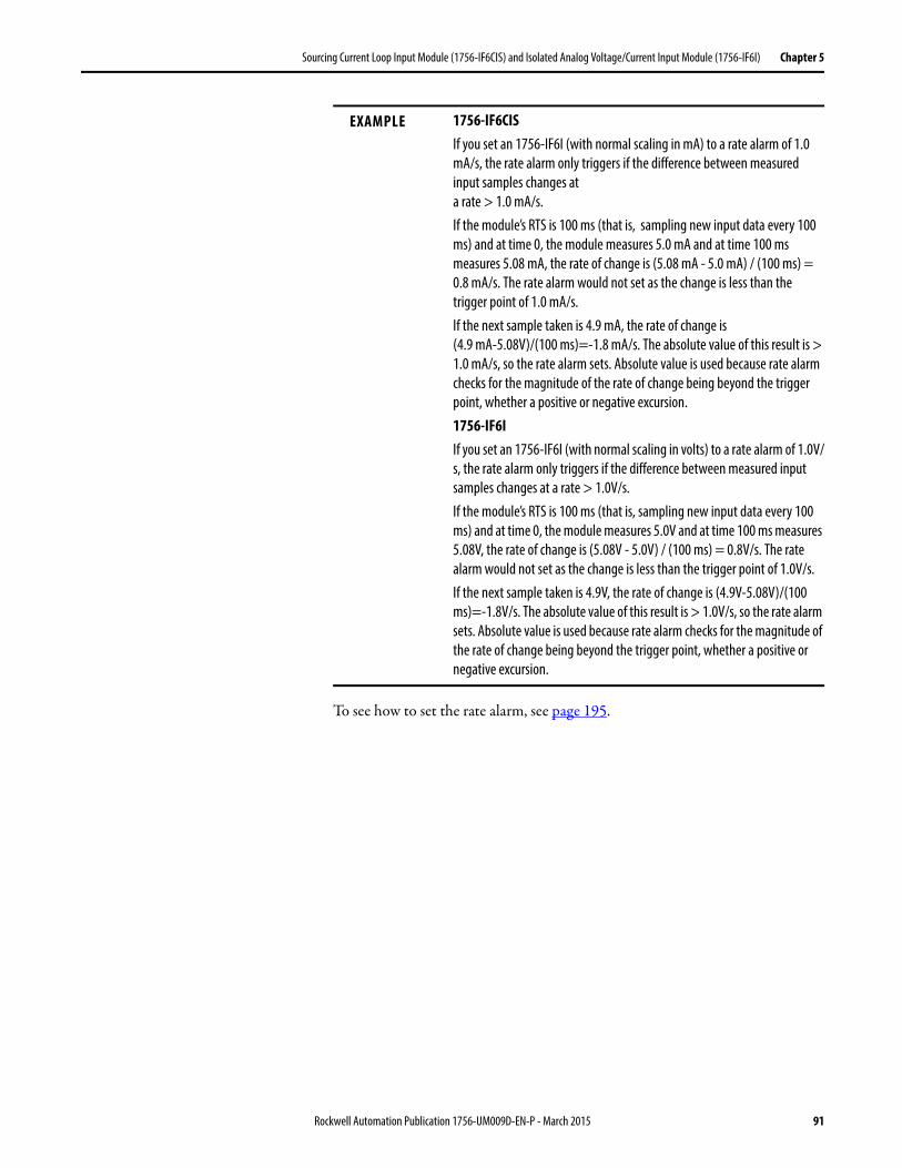
Sourcing Current Loop Input Module (1756-IF6CIS) and Isolated Analog Voltage/Current Input Module (1756-IF6I) Chapter 5
To see how to set the rate alarm, see page 195.
EXAMPLE 1756-IF6CISIf you set an 1756-IF6I (with normal scaling in mA) to a rate alarm of 1.0 mA/s, the rate alarm only triggers if the difference between measured input samples changes ata rate > 1.0 mA/s.If the module’s RTS is 100 ms (that is, sampling new input data every 100 ms) and at time 0, the module measures 5.0 mA and at time 100 ms measures 5.08 mA, the rate of change is (5.08 mA - 5.0 mA) / (100 ms) = 0.8 mA/s. The rate alarm would not set as the change is less than the trigger point of 1.0 mA/s.If the next sample taken is 4.9 mA, the rate of change is(4.9 mA-5.08V)/(100 ms)=-1.8 mA/s. The absolute value of this result is > 1.0 mA/s, so the rate alarm sets. Absolute value is used because rate alarm checks for the magnitude of the rate of change being beyond the trigger point, whether a positive or negative excursion.1756-IF6IIf you set an 1756-IF6I (with normal scaling in volts) to a rate alarm of 1.0V/s, the rate alarm only triggers if the difference between measured input samples changes at a rate > 1.0V/s.If the module’s RTS is 100 ms (that is, sampling new input data every 100 ms) and at time 0, the module measures 5.0V and at time 100 ms measures 5.08V, the rate of change is (5.08V - 5.0V) / (100 ms) = 0.8V/s. The rate alarm would not set as the change is less than the trigger point of 1.0V/s. If the next sample taken is 4.9V, the rate of change is (4.9V-5.08V)/(100 ms)=-1.8V/s. The absolute value of this result is > 1.0V/s, so the rate alarm sets. Absolute value is used because rate alarm checks for the magnitude of the rate of change being beyond the trigger point, whether a positive or negative excursion.
Rockwell Automation Publication 1756-UM009D-EN-P - March 2015 91
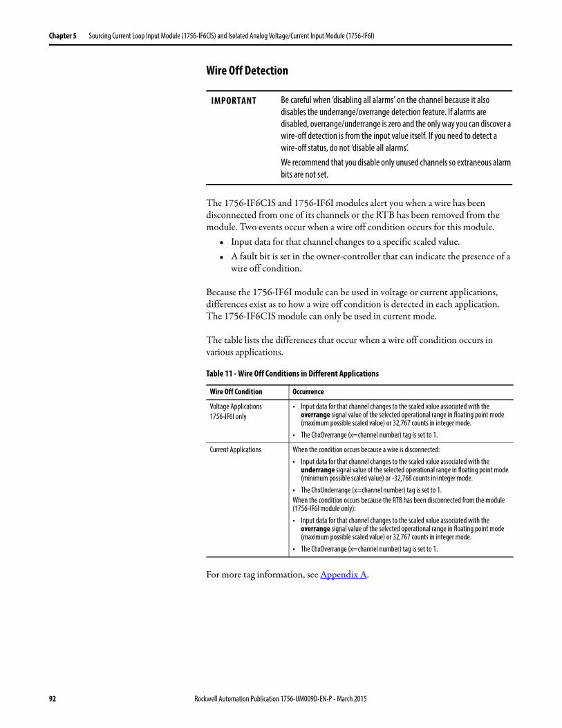
Chapter 5 Sourcing Current Loop Input Module (1756-IF6CIS) and Isolated Analog Voltage/Current Input Module (1756-IF6I)
Wire Off Detection
The 1756-IF6CIS and 1756-IF6I modules alert you when a wire has been disconnected from one of its channels or the RTB has been removed from the module. Two events occur when a wire off condition occurs for this module.
• Input data for that channel changes to a specific scaled value.• A fault bit is set in the owner-controller that can indicate the presence of a
wire off condition.
Because the 1756-IF6I module can be used in voltage or current applications, differences exist as to how a wire off condition is detected in each application. The 1756-IF6CIS module can only be used in current mode.
The table lists the differences that occur when a wire off condition occurs in various applications.
For more tag information, see Appendix A.
IMPORTANT Be careful when ‘disabling all alarms’ on the channel because it also disables the underrange/overrange detection feature. If alarms are disabled, overrange/underrange is zero and the only way you can discover a wire-off detection is from the input value itself. If you need to detect a wire-off status, do not ‘disable all alarms’.We recommend that you disable only unused channels so extraneous alarm bits are not set.
Table 11 - Wire Off Conditions in Different Applications
Wire Off Condition Occurrence
Voltage Applications1756-IF6I only
• Input data for that channel changes to the scaled value associated with the overrange signal value of the selected operational range in floating point mode (maximum possible scaled value) or 32,767 counts in integer mode.
• The ChxOverrange (x=channel number) tag is set to 1.
Current Applications When the condition occurs because a wire is disconnected:• Input data for that channel changes to the scaled value associated with the
underrange signal value of the selected operational range in floating point mode (minimum possible scaled value) or -32,768 counts in integer mode.
• The ChxUnderrange (x=channel number) tag is set to 1.When the condition occurs because the RTB has been disconnected from the module (1756-IF6I module only):• Input data for that channel changes to the scaled value associated with the
overrange signal value of the selected operational range in floating point mode (maximum possible scaled value) or 32,767 counts in integer mode.
• The ChxOverrange (x=channel number) tag is set to 1.
92 Rockwell Automation Publication 1756-UM009D-EN-P - March 2015
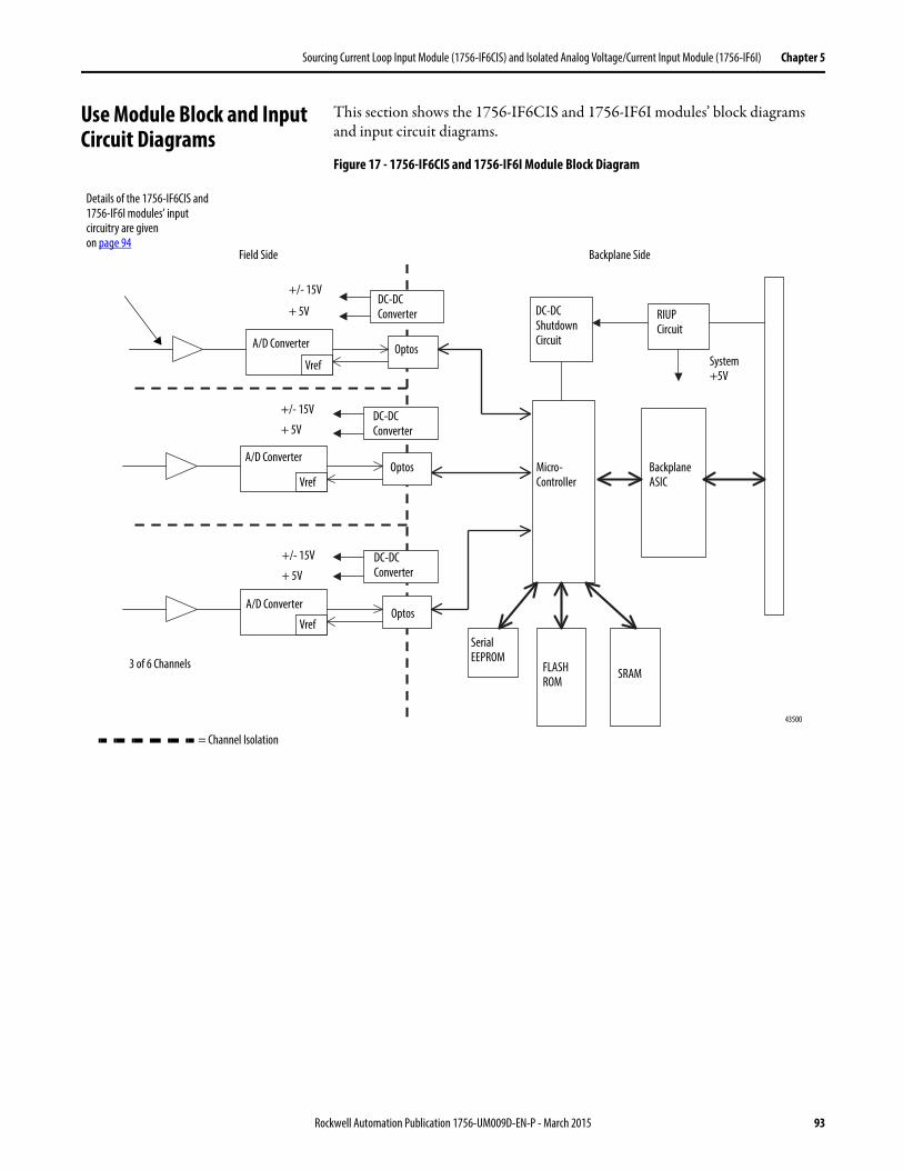
Sourcing Current Loop Input Module (1756-IF6CIS) and Isolated Analog Voltage/Current Input Module (1756-IF6I) Chapter 5
Use Module Block and Input Circuit Diagrams
This section shows the 1756-IF6CIS and 1756-IF6I modules’ block diagrams and input circuit diagrams.
Figure 17 - 1756-IF6CIS and 1756-IF6I Module Block Diagram
DC-DC Converter
A/D Converter
RIUP Circuit
43500
DC-DC Converter
VrefOptos
Micro-Controller
Backplane ASIC
Serial EEPROM
FLASH ROM
SRAM
System +5V
Field Side Backplane Side
DC-DC Shutdown Circuit
Vref
A/D ConverterOptos
+/- 15V
+ 5V
+/- 15V
+ 5V
Details of the 1756-IF6CIS and 1756-IF6I modules’ input circuitry are givenon page 94
DC-DC Converter
Vref
A/D ConverterOptos
+/- 15V
+ 5V
3 of 6 Channels
= Channel Isolation
Rockwell Automation Publication 1756-UM009D-EN-P - March 2015 93
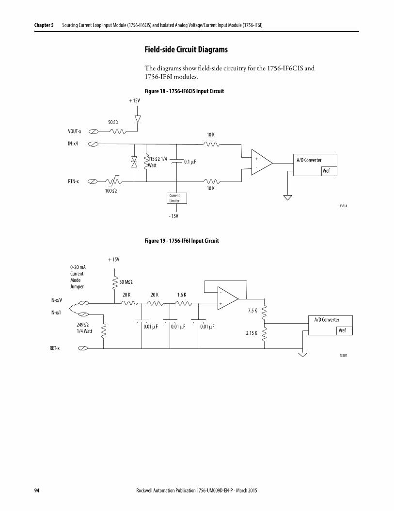
Chapter 5 Sourcing Current Loop Input Module (1756-IF6CIS) and Isolated Analog Voltage/Current Input Module (1756-IF6I)
Field-side Circuit Diagrams
The diagrams show field-side circuitry for the 1756-IF6CIS and1756-IF6I modules.
Figure 18 - 1756-IF6CIS Input Circuit
Figure 19 - 1756-IF6I Input Circuit
43514
RTN-x
+ 15V
0.1 F
VOUT-x
A/D Converter
10 K
50
Vref
10 K
IN-x/I
- 15V
100
115 1/4 Watt
Current Limiter
43507
RET-x
7.5 K
2.15 K
+ 15V
249 1/4 Watt
0.01 F
IN-x/V
A/D Converter0.01 F
30 M
20 K 20 K
0-20 mA Current Mode Jumper
Vref
1.6 K
0.01 F
IN-x/I
94 Rockwell Automation Publication 1756-UM009D-EN-P - March 2015
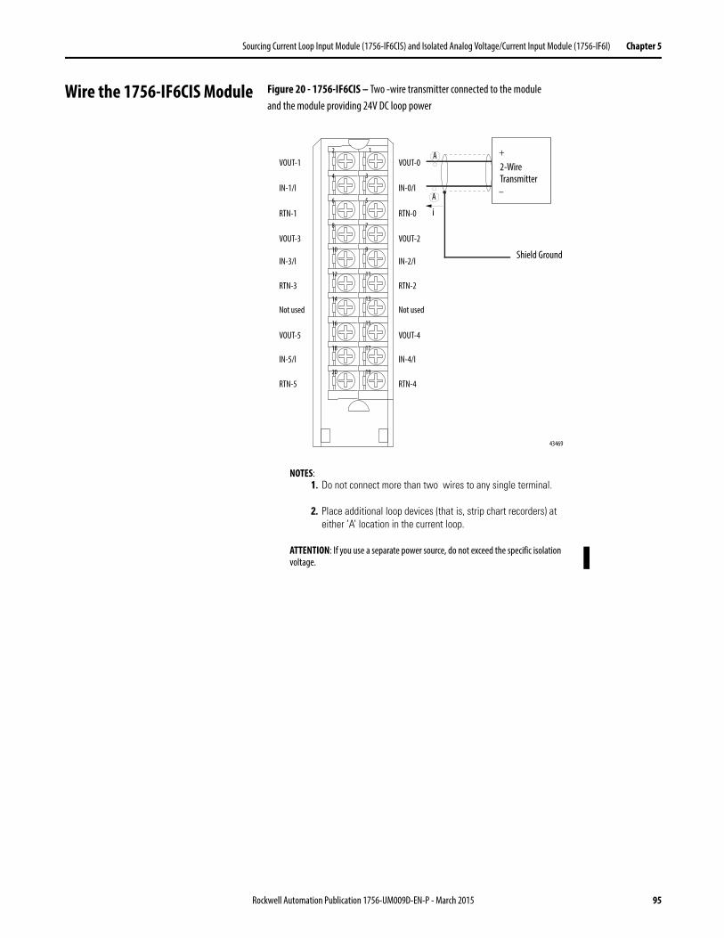
Sourcing Current Loop Input Module (1756-IF6CIS) and Isolated Analog Voltage/Current Input Module (1756-IF6I) Chapter 5
Wire the 1756-IF6CIS Module Figure 20 - 1756-IF6CIS – Two -wire transmitter connected to the moduleand the module providing 24V DC loop power
+
–
12
34
56
78
910
1112
1314
1516
1718
1920
VOUT-1
IN-1/I
RTN-1
VOUT-3
IN-3/I
RTN-3
Not used
VOUT-5
IN-5/I
RTN-5
VOUT-0
IN-0/I
RTN-0
VOUT-2
IN-2/I
RTN-2
Not used
VOUT-4
IN-4/I
RTN-4
2-Wire Transmitter
43469
Shield Ground
NOTES:1. Do not connect more than two wires to any single terminal.
2. Place additional loop devices (that is, strip chart recorders) at either ’A’ location in the current loop.
ATTENTION: If you use a separate power source, do not exceed the specific isolation voltage.
A
i
A
Rockwell Automation Publication 1756-UM009D-EN-P - March 2015 95
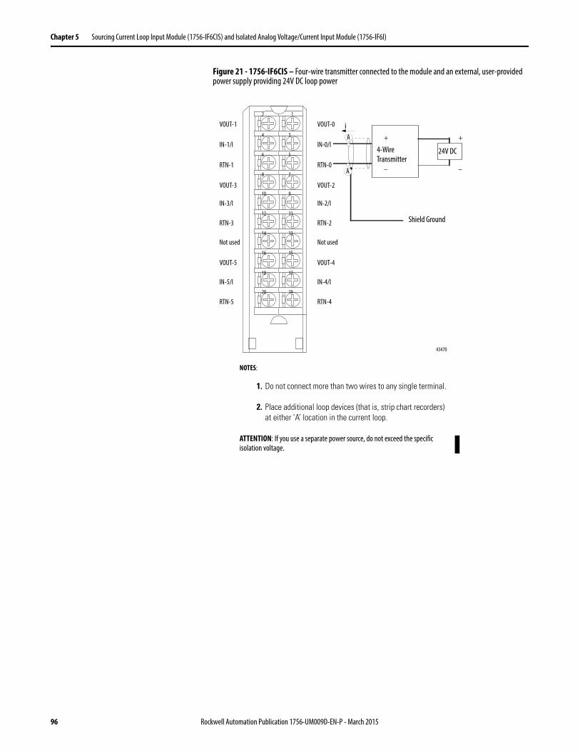
Chapter 5 Sourcing Current Loop Input Module (1756-IF6CIS) and Isolated Analog Voltage/Current Input Module (1756-IF6I)
Figure 21 - 1756-IF6CIS – Four-wire transmitter connected to the module and an external, user-provided power supply providing 24V DC loop power
+
–
12
34
56
78
910
1112
1314
1516
1718
1920
VOUT-1
IN-1/I
RTN-1
VOUT-3
IN-3/I
RTN-3
Not used
VOUT-5
IN-5/I
RTN-5
VOUT-0
IN-0/I
RTN-0
VOUT-2
IN-2/I
RTN-2
Not used
VOUT-4
IN-4/I
RTN-4
4-Wire Transmitter
43470
Shield Ground
+
–
NOTES:
1. Do not connect more than two wires to any single terminal.
2. Place additional loop devices (that is, strip chart recorders) at either ’A’ location in the current loop.
ATTENTION: If you use a separate power source, do not exceed the specific isolation voltage.
iA
A
24V DC
96 Rockwell Automation Publication 1756-UM009D-EN-P - March 2015
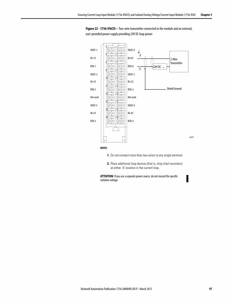
Sourcing Current Loop Input Module (1756-IF6CIS) and Isolated Analog Voltage/Current Input Module (1756-IF6I) Chapter 5
Figure 22 - 1756-IF6CIS – Two-wire transmitter connected to the module and an external,user-provided power supply providing 24V DC loop power
+–
12
34
56
78
910
1112
1314
1516
1718
1920
VOUT-1
IN-1/I
RTN-1
VOUT-3
IN-3/I
RTN-3
Not used
VOUT-5
IN-5/I
RTN-5
VOUT-0
IN-0/I
RTN-0
VOUT-2
IN-2/I
RTN-2
Not used
VOUT-4
IN-4/I
RTN-4
2-Wire Transmitter
43471
24V DC
Shield Ground
NOTES:
1. Do not connect more than two wires to any single terminal.
2. Place additional loop devices (that is, strip chart recorders) at either ’A’ location in the current loop.
ATTENTION: If you use a separate power source, do not exceed the specific isolation voltage.
iA
A
Rockwell Automation Publication 1756-UM009D-EN-P - March 2015 97
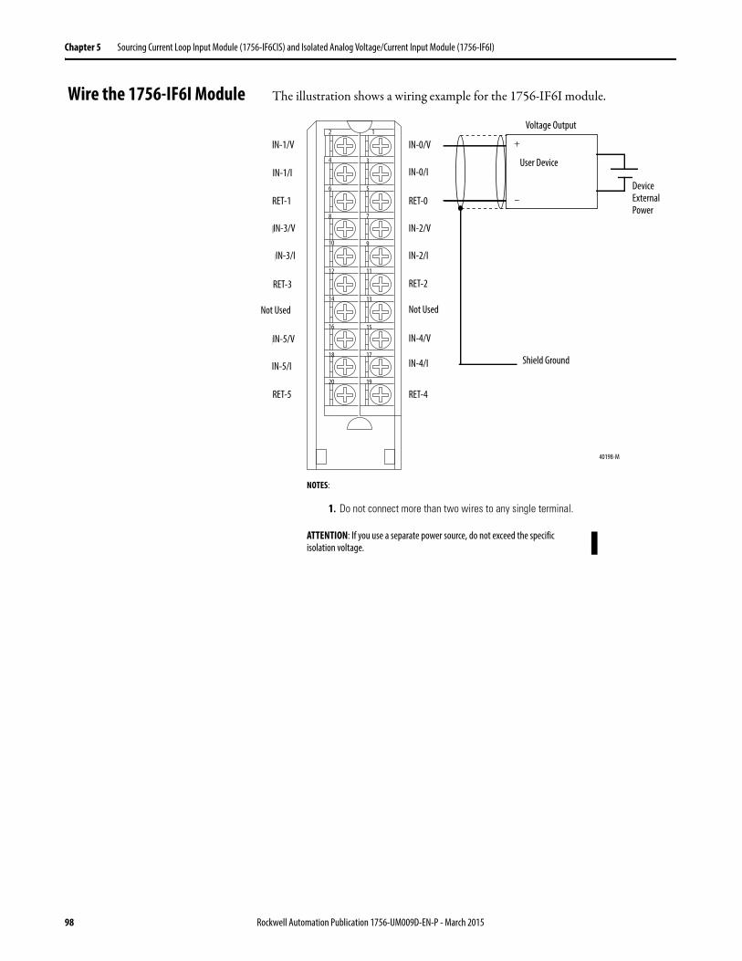
Chapter 5 Sourcing Current Loop Input Module (1756-IF6CIS) and Isolated Analog Voltage/Current Input Module (1756-IF6I)
Wire the 1756-IF6I Module The illustration shows a wiring example for the 1756-IF6I module.
Voltage Input
User Analog
Input Device
Shield Ground
+
–
IN-0/V
IN-0/I
RET-0
IN-2/V
IN-2/I
RET-2
Not used
IN-4/V
IN-4/I
RET-4
IN-1/V
IN-1/I
RET-1
IN-3/V
IN-3/I
RET-3
Not used
IN-5/V
IN-5/I
RET-5
12
34
56
78
910
1112
1314
1516
1718
1920
40198-M
Device External Power
NOTES:
1. Do not connect more than two wires to any single terminal.
ATTENTION: If you use a separate power source, do not exceed the specific isolation voltage.
User Device
Shield Ground
IN-1/V
IN-1/I
RET-1
IN-3/V
IN-3/I
RET-3
Not Used
IN-5/V
IN-5/I
RET-5
IN-0/V
IN-0/I
RET-0
IN-2/V
IN-2/I
RET-2
Not Used
IN-4/V
IN-4/I
RET-4
Voltage Output
40198-M
98 Rockwell Automation Publication 1756-UM009D-EN-P - March 2015
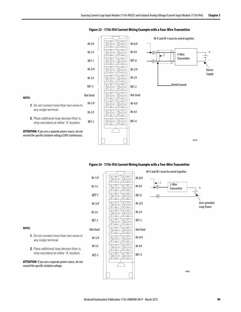
Sourcing Current Loop Input Module (1756-IF6CIS) and Isolated Analog Voltage/Current Input Module (1756-IF6I) Chapter 5
Figure 23 - 1756-IF6I Current Wiring Example with a Four-Wire Transmitter
Figure 24 - 1756-IF6I Current Wiring Example with a Two-Wire Transmitter
4-WireTransmitter
Shield Ground
+
–
IN-0/V
IN-0/I
RET-0
IN-2/V
IN-2/I
RET-2
Not used
IN-4/V
IN-4/I
RET-4
IN-1/V
IN-1/I
RET-1
IN-3/V
IN-3/I
RET-3
Not used
IN-5/V
IN-5/I
RET-5
12
34
56
78
910
1112
1314
1516
1718
1920
40199-M
i+
-
A
A
IN-V and IN-I must be wired together.
4-Wire Transmitter
Shield Ground
40199
IN-I/V
IN-1/I
RET-1
IN-3/V
IN-3/I
RET-3
Not Used
IN-5/V
IN-5/I
RET-5
IN-0/V
IN-0/I
RET-0
IN-2/V
IN-2/I
RET-2
Not Used
IN-4/V
IN-4/I
RET-4
i
NOTES:
1. Do not connect more than two wires to any single terminal.
2. Place additional loop devices (that is, strip recorders) at either ’A’ location.
ATTENTION: If you use a separate power source, do not exceed the specific isolation voltag,e250V (continuous).
Device Supply
12
34
56
78
910
1112
1314
1516
1718
1920
IN-1/V
IN-1/I
RET-1
IN-3/V
IN-3/I
RET-3
Not used
IN-5/V
IN-5/I
RET-5
IN-0/V
IN-0/I
RET-0
IN-2/V
IN-2/I
RET-2
Not used
IN-4/V
IN-4/I
RET-4
2-WireTransmitter
(+)(–)
40893-M
i+
-
A
A
IN-V and IN-I must be wired together.
40893
i 2-Wire Transmitter
IN-1/V
IN-1/I
RET-1
IN-3/V
IN-3/I
RET-3
Not Used
IN-5/V
IN-5/I
RET-5
IN-0/V
IN-0/I
RET-0
IN-2/V
IN-2/I
RET-2
Not Used
IN-4/V
IN-4/I
RET-4
NOTES:
1. Do not connect more than two wires to any single terminal.
2. Place additional loop devices (that is, strip recorders) at either ’A’ location.
ATTENTION: If you use a separate power source, do not exceed the specific isolation voltage.
User-provided Loop Power
Rockwell Automation Publication 1756-UM009D-EN-P - March 2015 99
Chapter 5 Sourcing Current Loop Input Module (1756-IF6CIS) and Isolated Analog Voltage/Current Input Module (1756-IF6I)
1756-IF6CIS or 1756-IF6I Module Fault and Status Reporting
The 1756-IF6CIS and 1756-IF6I modules multicast status and fault data to the owner/listening controllers with its channel data. The fault data is arranged in such a manner as to let you choose the level of granularity for examining fault conditions.
Three levels of tags work together to provide increasing degree of detail as to the specific cause of faults on the module.
The table lists tags that can be examined in ladder logic to indicate when afault occurs.
Tag Description
Module Fault Word This word provides fault summary reporting. Its tag name is ModuleFaults.
Channel Fault Word This word provides underrange, overrange and communications fault reporting. Its tag name is ChannelFaults.
Channel Status Words This word provides individual channel underrange and overrange fault reporting for process alarms, rate alarms, and calibration faults. Its tag name is ChxStatus.
IMPORTANT Differences exist between floating point and integer modes as they relate to module fault reporting. These differences are explained in the following two sections.
100 Rockwell Automation Publication 1756-UM009D-EN-P - March 2015
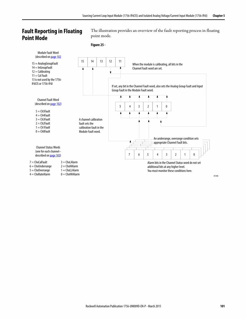
Sourcing Current Loop Input Module (1756-IF6CIS) and Isolated Analog Voltage/Current Input Module (1756-IF6I) Chapter 5
Fault Reporting in Floating Point Mode
The illustration provides an overview of the fault reporting process in floating point mode.
Figure 25 -
Module Fault Word(described on page 102
Channel Fault Word(described on page 102)
Channel Status Words(one for each channel–described on page 103)
15 14 13 12 11
5 4 3 2 1 0
5 4 3 2 1 07 6
15 = AnalogGroupFault14 = InGroupFault12 = Calibrating11 = Cal Fault13 is not used by the 1756-IF6CIS or 1756-IF6I
5 = Ch5Fault4 = Ch4Fault3 = Ch3Fault2 = Ch2Fault1 = Ch1Fault0 = Ch0Fault
7 = ChxCalFault6 = ChxUnderrange5 = ChxOverrange4 = ChxRateAlarm
If set, any bit in the Channel Fault word, also sets the Analog Group Fault and Input Group Fault in the Module Fault word.
A channel calibration fault sets the calibration fault in the Module Fault word.
Alarm bits in the Channel Status word do not set additional bits at any higher level.You must monitor these conditions here.
3 = ChxLAlarm2 = ChxHAlarm1 = ChxLLAlarm0 = ChxHHAlarm
An underrange, overrange condition sets appropriate Channel Fault bits.
When the module is calibrating, all bits in the Channel Fault word are set.
41345
Rockwell Automation Publication 1756-UM009D-EN-P - March 2015 101
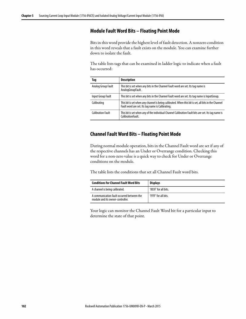
Chapter 5 Sourcing Current Loop Input Module (1756-IF6CIS) and Isolated Analog Voltage/Current Input Module (1756-IF6I)
Module Fault Word Bits – Floating Point Mode
Bits in this word provide the highest level of fault detection. A nonzero condition in this word reveals that a fault exists on the module. You can examine further down to isolate the fault.
The table lists tags that can be examined in ladder logic to indicate when a fault has occurred:
Channel Fault Word Bits – Floating Point Mode
During normal module operation, bits in the Channel Fault word are set if any of the respective channels has an Under or Overrange condition. Checking this word for a non-zero value is a quick way to check for Under or Overrange conditions on the module.
The table lists the conditions that set all Channel Fault word bits.
Your logic can monitor the Channel Fault Word bit for a particular input to determine the state of that point.
Tag Description
Analog Group Fault This bit is set when any bits in the Channel Fault word are set. Its tag name is AnalogGroupFault.
Input Group Fault This bit is set when any bits in the Channel Fault word are set. Its tag name is InputGroup.
Calibrating This bit is set when any channel is being calibrated. When this bit is set, all bits in the Channel Fault word are set. Its tag name is Calibrating.
Calibration Fault This bit is set when any of the individual Channel Calibration Fault bits are set. Its tag name is CalibrationFault.
Conditions for Channel Fault Word Bits Displays
A channel is being calibrated. ’003F’ for all bits.
A communication fault occurred between the module and its owner-controller.
’FFFF’ for all bits.
102 Rockwell Automation Publication 1756-UM009D-EN-P - March 2015
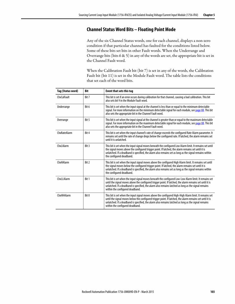
Sourcing Current Loop Input Module (1756-IF6CIS) and Isolated Analog Voltage/Current Input Module (1756-IF6I) Chapter 5
Channel Status Word Bits – Floating Point Mode
Any of the six Channel Status words, one for each channel, displays a non-zero condition if that particular channel has faulted for the conditions listed below. Some of these bits set bits in other Fault words. When the Underrange and Overrange bits (bits 6 & 5) in any of the words are set, the appropriate bit is set in the Channel Fault word.
When the Calibration Fault bit (bit 7) is set in any of the words, the Calibration Fault bit (bit 11) is set in the Module Fault word. The table lists the conditions that set each of the word bits.
Tag (Status word) Bit Event that sets this tag
ChxCalFault Bit 7 This bit is set if an error occurs during calibration for that channel, causing a bad calibration. This bit also sets bit 9 in the Module Fault word.
Underrange Bit 6 This bit is set when the input signal at the channel is less than or equal to the minimum detectable signal. For more information on the minimum detectable signal for each module, see page 88. This bit also sets the appropriate bit in the Channel Fault word.
Overrange Bit 5 This bit is set when the input signal at the channel is greater than or equal to the maximum detectable signal. For more information on the maximum detectable signal for each module, see page 88. This bit also sets the appropriate bit in the Channel Fault word.
ChxRateAlarm Bit 4 This bit is set when the input channel’s rate of change exceeds the configured Rate Alarm parameter. It remains set until the rate of change drops below the configured rate. If latched, the alarm remains set until it is unlatched.
ChxLAlarm BIt 3 This bit is set when the input signal moves beneath the configured Low Alarm limit. It remains set until the signal moves above the configured trigger point. If latched, the alarm remains set until it is unlatched. If a deadband is specified, the alarm also remains set as long as the signal remains within the configured deadband.
ChxHAlarm Bit 2 This bit is set when the input signal moves above the configured High Alarm limit. It remains set until the signal moves below the configured trigger point. If latched, the alarm remains set until it is unlatched. If a deadband is specified, the alarm also remains set as long as the signal remains within the configured deadband.
ChxLLAlarm Bit 1 This bit is set when the input signal moves beneath the configured Low-Low Alarm limit. It remains set until the signal moves above the configured trigger point. If latched, the alarm remains set until it is unlatched. If a deadband is specified, the alarm also remains latched as long as the signal remains within the configured deadband.
ChxHHAlarm Bit 0 This bit is set when the input signal moves above the configured High-High Alarm limit. It remains set until the signal moves below the configured trigger point. If latched, the alarm remains set until it is unlatched. If a deadband is specified, the alarm also remains latched as long as the signal remains within the configured deadband.
Rockwell Automation Publication 1756-UM009D-EN-P - March 2015 103
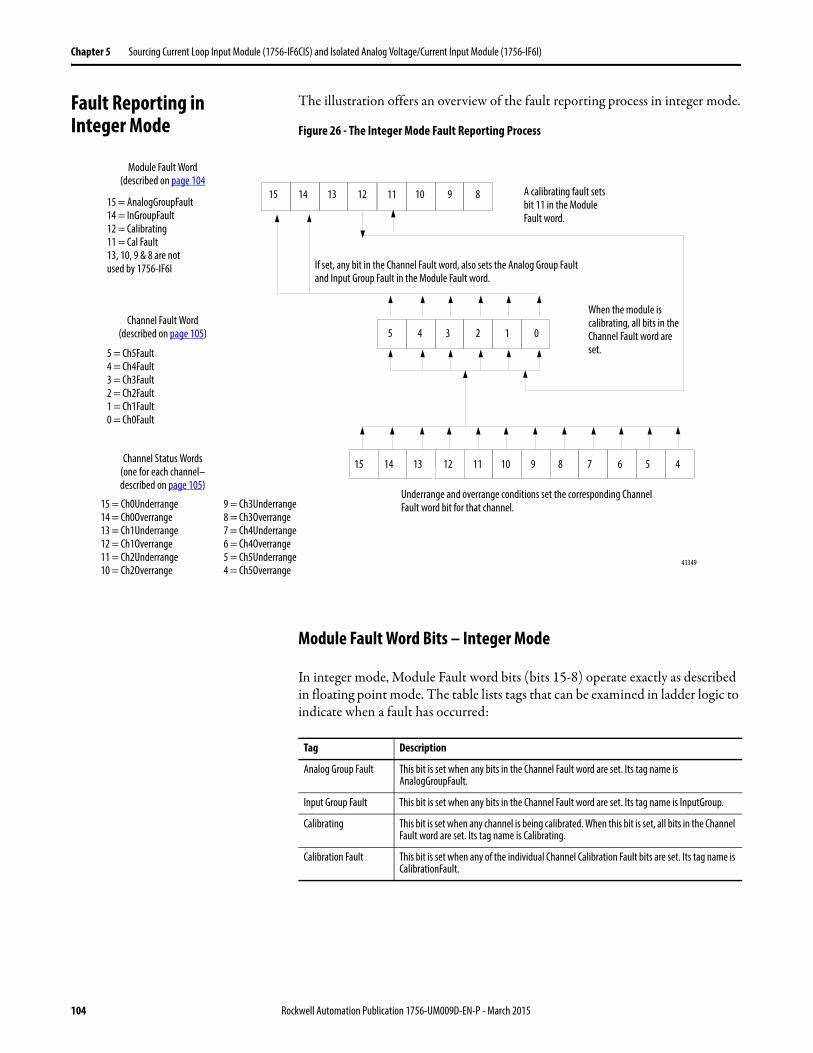
Chapter 5 Sourcing Current Loop Input Module (1756-IF6CIS) and Isolated Analog Voltage/Current Input Module (1756-IF6I)
Fault Reporting in Integer Mode
The illustration offers an overview of the fault reporting process in integer mode.
Figure 26 - The Integer Mode Fault Reporting Process
Module Fault Word Bits – Integer Mode
In integer mode, Module Fault word bits (bits 15-8) operate exactly as described in floating point mode. The table lists tags that can be examined in ladder logic to indicate when a fault has occurred:
15 14 13 12 11 10 9 8
5 4 3 2 1 0
5 49 8 7 6
15 = AnalogGroupFault14 = InGroupFault12 = Calibrating11 = Cal Fault13, 10, 9 & 8 are notused by 1756-IF6I
5 = Ch5Fault4 = Ch4Fault3 = Ch3Fault2 = Ch2Fault1 = Ch1Fault0 = Ch0Fault
15 = Ch0Underrange14 = Ch0Overrange13 = Ch1Underrange12 = Ch1Overrange11 = Ch2Underrange10 = Ch2Overrange
15 14 13 12 11 10
9 = Ch3Underrange8 = Ch3Overrange7 = Ch4Underrange6 = Ch4Overrange5 = Ch5Underrange4 = Ch5Overrange
Underrange and overrange conditions set the corresponding Channel Fault word bit for that channel.
When the module is calibrating, all bits in the Channel Fault word are set.
If set, any bit in the Channel Fault word, also sets the Analog Group Fault and Input Group Fault in the Module Fault word.
A calibrating fault sets bit 11 in the Module Fault word.
Module Fault Word(described on page 104
Channel Fault Word(described on page 105)
Channel Status Words(one for each channel–described on page 105)
41349
Tag Description
Analog Group Fault This bit is set when any bits in the Channel Fault word are set. Its tag name is AnalogGroupFault.
Input Group Fault This bit is set when any bits in the Channel Fault word are set. Its tag name is InputGroup.
Calibrating This bit is set when any channel is being calibrated. When this bit is set, all bits in the Channel Fault word are set. Its tag name is Calibrating.
Calibration Fault This bit is set when any of the individual Channel Calibration Fault bits are set. Its tag name is CalibrationFault.
104 Rockwell Automation Publication 1756-UM009D-EN-P - March 2015
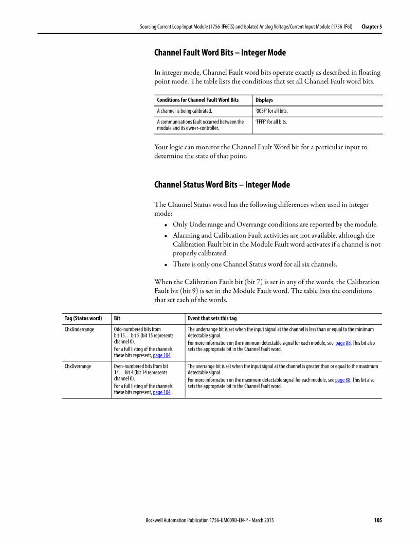
Sourcing Current Loop Input Module (1756-IF6CIS) and Isolated Analog Voltage/Current Input Module (1756-IF6I) Chapter 5
Channel Fault Word Bits – Integer Mode
In integer mode, Channel Fault word bits operate exactly as described in floating point mode. The table lists the conditions that set all Channel Fault word bits.
Your logic can monitor the Channel Fault Word bit for a particular input to determine the state of that point.
Channel Status Word Bits – Integer Mode
The Channel Status word has the following differences when used in integer mode:
• Only Underrange and Overrange conditions are reported by the module.• Alarming and Calibration Fault activities are not available, although the
Calibration Fault bit in the Module Fault word activates if a channel is not properly calibrated.
• There is only one Channel Status word for all six channels.
When the Calibration Fault bit (bit 7) is set in any of the words, the Calibration Fault bit (bit 9) is set in the Module Fault word. The table lists the conditions that set each of the words.
Conditions for Channel Fault Word Bits Displays
A channel is being calibrated. ’003F’ for all bits.
A communications fault occurred between the module and its owner-controller.
’FFFF’ for all bits.
Tag (Status word) Bit Event that sets this tag
ChxUnderrange Odd-numbered bits frombit 15…bit 5 (bit 15 represents channel 0).For a full listing of the channels these bits represent, page 104.
The underrange bit is set when the input signal at the channel is less than or equal to the minimum detectable signal.For more information on the minimum detectable signal for each module, see page 88. This bit also sets the appropriate bit in the Channel Fault word.
ChxOverrange Even-numbered bits from bit 14…bit 4 (bit 14 represents channel 0).For a full listing of the channels these bits represent, page 104.
The overrange bit is set when the input signal at the channel is greater than or equal to the maximum detectable signal.For more information on the maximum detectable signal for each module, see page 88. This bit also sets the appropriate bit in the Channel Fault word.
Rockwell Automation Publication 1756-UM009D-EN-P - March 2015 105

Chapter 5 Sourcing Current Loop Input Module (1756-IF6CIS) and Isolated Analog Voltage/Current Input Module (1756-IF6I)
Notes:
106 Rockwell Automation Publication 1756-UM009D-EN-P - March 2015
Chapter 6
Temperature-measuring Analog Modules (1756-IR6I, 1756-IT6I, and 1756-IT6I2)
Introduction This chapter describes features specific to temperature-measuring ControlLogix analog modules. These units linearize their respective sensor inputs into a temperature value. The 1756-IR6I uses ohms for temperature conversions and the two thermocouple modules (1756-IT6I, 1756-IT6I2)convert millivolts.
These modules also support features described in Chapter 3. See the table for some of these features.
Topic Page
Choose a Data Format 108
Temperature-measuring Module Features 109
Differences Between the 1756-IT6I and 1756-IT6I2 Modules 118
Use Module Block and Input Circuit Diagrams 123
Wire the Modules 125
1756-IT6I Wiring Example 126
1756-IT6I2 Wiring Example 127
Fault and Status Reporting 128
Fault Reporting in Floating Point Mode 129
Fault Reporting in Integer Mode 132
Feature Page
Removal and Insertion Under Power (RIUP) 34
Module Fault Reporting 34
Configurable Software 34
Electronic Keying 34
Access to System Clock for Timestamp Functions 36
Rolling Timestamp 36
Producer/Consumer Model 36
Status Indicator Information 37
Full Class I Division 2 Compliance 37
Agency Certification 37
Field Calibration 37
Sensor Offset 38
Latching of Alarms 38
Rockwell Automation Publication 1756-UM009D-EN-P - March 2015 107
Chapter 6 Temperature-measuring Analog Modules (1756-IR6I, 1756-IT6I, and 1756-IT6I2)
Choose a Data Format Data format determines how the data is returned from the module to the owner-controller and the features that are available to your application. You choose a data format when you choose a Communication Format.
You can choose one of these data formats:• Integer mode• Floating point mode
The table shows features that are available in each format.
For more information on input and output data formats, see page 189in Chapter 10.
Data Format Features Available: Features Not Available
Integer mode Multiple input rangesNotch filterReal time samplingCold junction temperature ison 1756-IT6I and 1756-IT6I2 modules only
Temperature linearizationProcess alarmsDigital filteringRate alarms
Floating point mode All features N/A
IMPORTANT Integer mode does not support temperature conversion on temperature-measuring modules. If you choose integer mode, the 1756-IR6I is strictly an ohms () module and the1756-IT6I and 1756-IT6I2 are strictly millivolts (mV) modules.
108 Rockwell Automation Publication 1756-UM009D-EN-P - March 2015
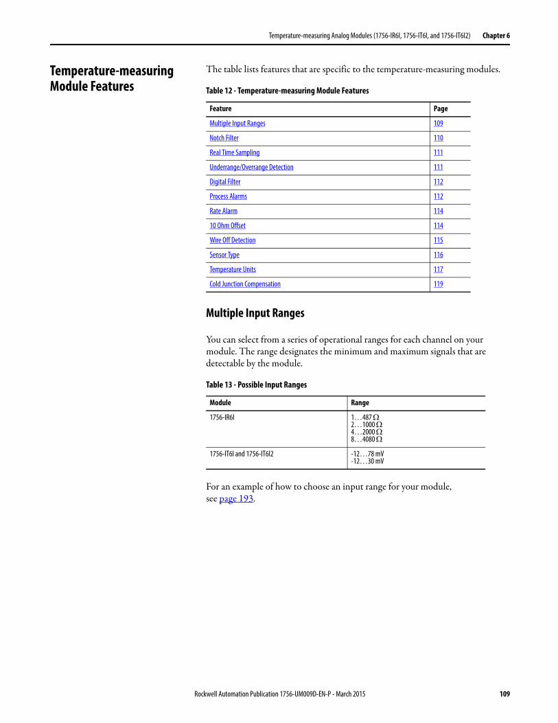
Temperature-measuring Analog Modules (1756-IR6I, 1756-IT6I, and 1756-IT6I2) Chapter 6
Temperature-measuring Module Features
The table lists features that are specific to the temperature-measuring modules.
Multiple Input Ranges
You can select from a series of operational ranges for each channel on your module. The range designates the minimum and maximum signals that are detectable by the module.
For an example of how to choose an input range for your module,see page 193.
Table 12 - Temperature-measuring Module Features
Feature Page
Multiple Input Ranges 109
Notch Filter 110
Real Time Sampling 111
Underrange/Overrange Detection 111
Digital Filter 112
Process Alarms 112
Rate Alarm 114
10 Ohm Offset 114
Wire Off Detection 115
Sensor Type 116
Temperature Units 117
Cold Junction Compensation 119
Table 13 - Possible Input Ranges
Module Range
1756-IR6I 1…487 2…1000 4…2000 8…4080
1756-IT6I and 1756-IT6I2 -12…78 mV-12…30 mV
Rockwell Automation Publication 1756-UM009D-EN-P - March 2015 109
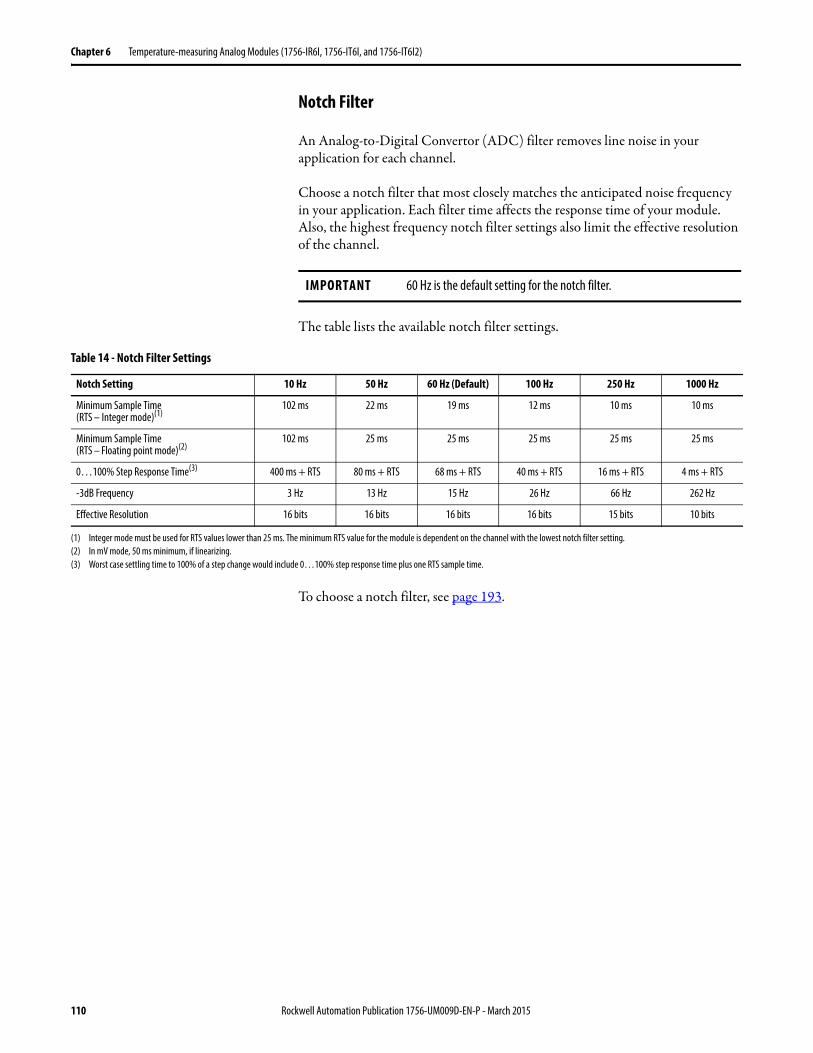
Chapter 6 Temperature-measuring Analog Modules (1756-IR6I, 1756-IT6I, and 1756-IT6I2)
Notch Filter
An Analog-to-Digital Convertor (ADC) filter removes line noise in your application for each channel.
Choose a notch filter that most closely matches the anticipated noise frequency in your application. Each filter time affects the response time of your module. Also, the highest frequency notch filter settings also limit the effective resolution of the channel.
The table lists the available notch filter settings.
To choose a notch filter, see page 193.
IMPORTANT 60 Hz is the default setting for the notch filter.
Table 14 - Notch Filter Settings
Notch Setting 10 Hz 50 Hz 60 Hz (Default) 100 Hz 250 Hz 1000 Hz
Minimum Sample Time(RTS – Integer mode)(1)
102 ms 22 ms 19 ms 12 ms 10 ms 10 ms
Minimum Sample Time(RTS – Floating point mode)(2)
102 ms 25 ms 25 ms 25 ms 25 ms 25 ms
0…100% Step Response Time(3) 400 ms + RTS 80 ms + RTS 68 ms + RTS 40 ms + RTS 16 ms + RTS 4 ms + RTS
-3dB Frequency 3 Hz 13 Hz 15 Hz 26 Hz 66 Hz 262 Hz
Effective Resolution 16 bits 16 bits 16 bits 16 bits 15 bits 10 bits
(1) Integer mode must be used for RTS values lower than 25 ms. The minimum RTS value for the module is dependent on the channel with the lowest notch filter setting.(2) In mV mode, 50 ms minimum, if linearizing.(3) Worst case settling time to 100% of a step change would include 0…100% step response time plus one RTS sample time.
110 Rockwell Automation Publication 1756-UM009D-EN-P - March 2015
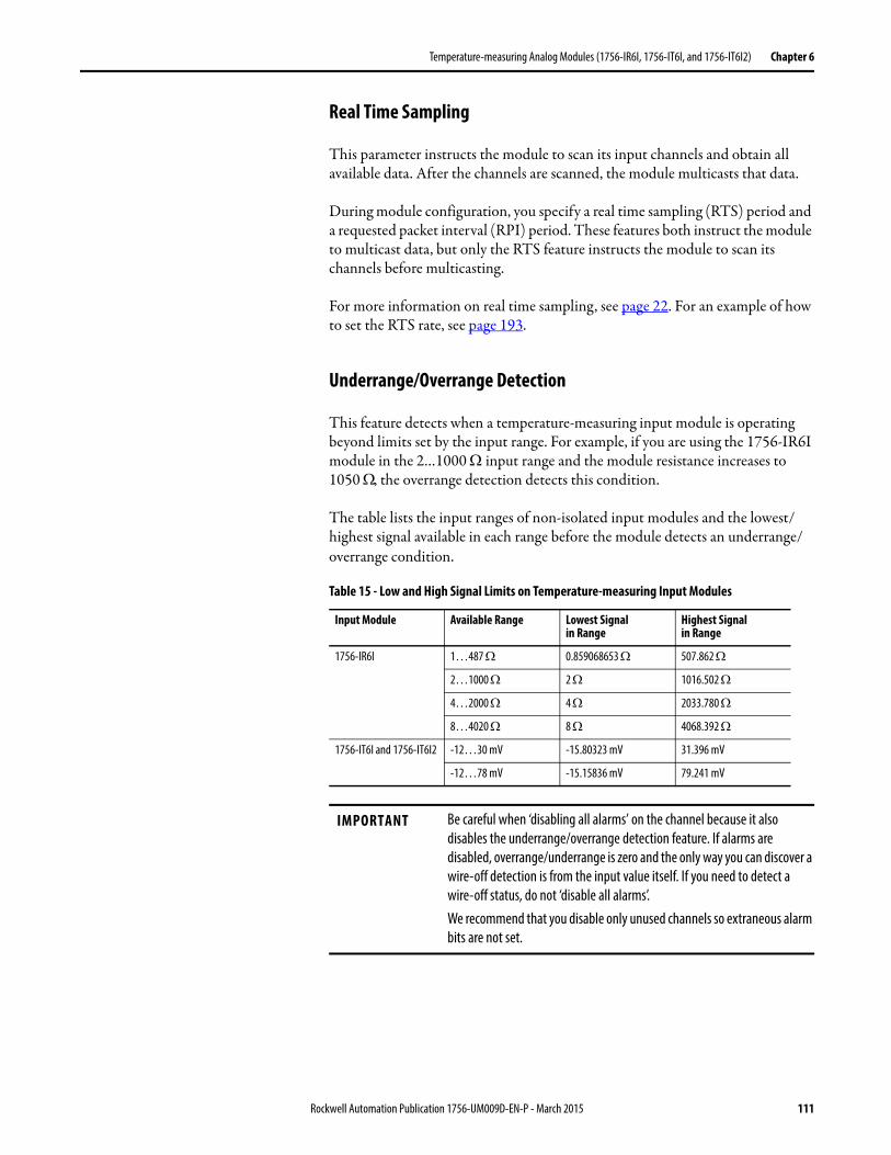
Temperature-measuring Analog Modules (1756-IR6I, 1756-IT6I, and 1756-IT6I2) Chapter 6
Real Time Sampling
This parameter instructs the module to scan its input channels and obtain all available data. After the channels are scanned, the module multicasts that data.
During module configuration, you specify a real time sampling (RTS) period and a requested packet interval (RPI) period. These features both instruct the module to multicast data, but only the RTS feature instructs the module to scan its channels before multicasting.
For more information on real time sampling, see page 22. For an example of how to set the RTS rate, see page 193.
Underrange/Overrange Detection
This feature detects when a temperature-measuring input module is operating beyond limits set by the input range. For example, if you are using the 1756-IR6I module in the 2…1000 input range and the module resistance increases to 1050 , the overrange detection detects this condition.
The table lists the input ranges of non-isolated input modules and the lowest/highest signal available in each range before the module detects an underrange/overrange condition.
Table 15 - Low and High Signal Limits on Temperature-measuring Input Modules
Input Module Available Range Lowest Signal in Range
Highest Signal in Range
1756-IR6I 1…487 0.859068653 507.862
2…1000 2 1016.502
4…2000 4 2033.780
8…4020 8 4068.392
1756-IT6I and 1756-IT6I2 -12…30 mV -15.80323 mV 31.396 mV
-12…78 mV -15.15836 mV 79.241 mV
IMPORTANT Be careful when ‘disabling all alarms’ on the channel because it also disables the underrange/overrange detection feature. If alarms are disabled, overrange/underrange is zero and the only way you can discover a wire-off detection is from the input value itself. If you need to detect a wire-off status, do not ‘disable all alarms’.We recommend that you disable only unused channels so extraneous alarm bits are not set.
Rockwell Automation Publication 1756-UM009D-EN-P - March 2015 111
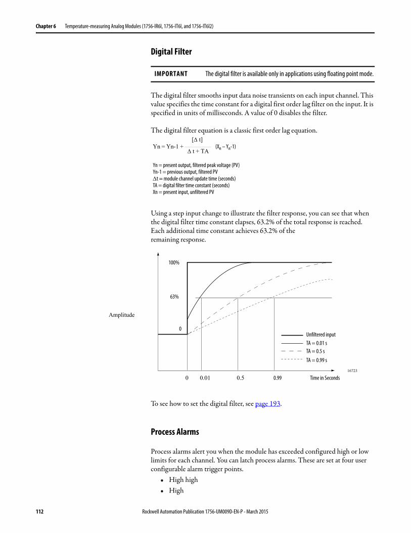
Chapter 6 Temperature-measuring Analog Modules (1756-IR6I, 1756-IT6I, and 1756-IT6I2)
Digital Filter
The digital filter smooths input data noise transients on each input channel. This value specifies the time constant for a digital first order lag filter on the input. It is specified in units of milliseconds. A value of 0 disables the filter.
The digital filter equation is a classic first order lag equation.
Using a step input change to illustrate the filter response, you can see that when the digital filter time constant elapses, 63.2% of the total response is reached. Each additional time constant achieves 63.2% of theremaining response.
To see how to set the digital filter, see page 193.
Process Alarms
Process alarms alert you when the module has exceeded configured high or low limits for each channel. You can latch process alarms. These are set at four user configurable alarm trigger points.
• High high• High
IMPORTANT The digital filter is available only in applications using floating point mode.
Yn = Yn-1 + (Xn – Yn-1)[ t]
t + TA
Yn = present output, filtered peak voltage (PV)Yn-1 = previous output, filtered PVt = module channel update time (seconds)TA = digital filter time constant (seconds)Xn = present input, unfiltered PV
0 0.01 0.5 0.99 Time in Seconds16723
100%
63%
0
Amplitude
Unfiltered inputTA = 0.01 sTA = 0.5 s
TA = 0.99 s
112 Rockwell Automation Publication 1756-UM009D-EN-P - March 2015
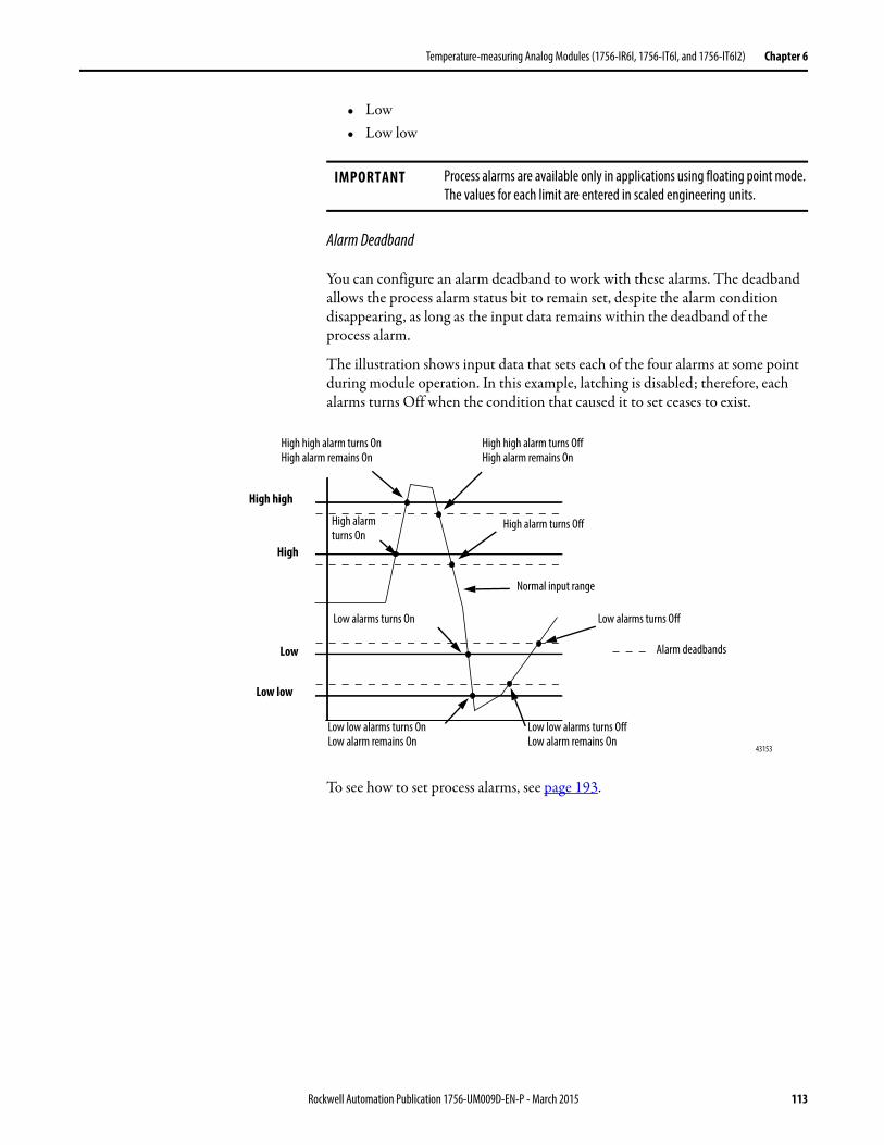
Temperature-measuring Analog Modules (1756-IR6I, 1756-IT6I, and 1756-IT6I2) Chapter 6
• Low• Low low
Alarm Deadband
You can configure an alarm deadband to work with these alarms. The deadband allows the process alarm status bit to remain set, despite the alarm condition disappearing, as long as the input data remains within the deadband of the process alarm.
The illustration shows input data that sets each of the four alarms at some point during module operation. In this example, latching is disabled; therefore, each alarms turns Off when the condition that caused it to set ceases to exist.
To see how to set process alarms, see page 193.
IMPORTANT Process alarms are available only in applications using floating point mode. The values for each limit are entered in scaled engineering units.
43153
High high
Low low
Low
High
Alarm deadbands
High high alarm turns OffHigh alarm remains On
High high alarm turns OnHigh alarm remains On
Normal input range
Low low alarms turns OffLow alarm remains On
High alarm turns Off
Low low alarms turns OnLow alarm remains On
Low alarms turns OffLow alarms turns On
High alarm turns On
Rockwell Automation Publication 1756-UM009D-EN-P - March 2015 113
Chapter 6 Temperature-measuring Analog Modules (1756-IR6I, 1756-IT6I, and 1756-IT6I2)
Rate Alarm
The rate alarm triggers if the rate of change between input samples for each channel exceeds the specified trigger point for that channel. This feature is available only in applications using floating point.
To see how to set the rate alarm, see page 193.
10 Ohm Offset
With this feature, you can compensate for a small offset error in a 10 copper RTD. Values can range from -0.99…0.99 in units of0.01 . For example, if the resistance of a copper RTD used with a channel is 9.74 at 25 oC, you would enter -0.26 in this field.
To see how to set the 10 Ohm Offset, see page 198.
IMPORTANT You must use RSLogix 5000 software, version 12 or later, and module firmware version 1.10 or later, to use the rate alarm for a non-ohm input on the 1756-IR6I module and a non-millivolt input on the 1756-IT6I and 1756-IT6I2 modules.
EXAMPLE If you set a 1756-IT6I2 module (with normal scaling in Celsius) to a rate alarm of 100.1 °C/s, the rate alarm only triggers if the difference between measured input samples changes at arate > 100.1 °C/s.If the module’s RTS is 100 ms (that is, sampling new input data every 100 ms) and at time 0, the module measures 355 °C and at time 100 ms measures 363 °C, the rate of change is(363…355 °C) / (100 ms) = 80 °C/s. The rate alarm would not set as the change is less than the trigger point of 100.1 °C/s.If the next sample taken is 350.3 °C, the rate of change is (350.3…363 °C)/(100 ms)=-127 °C/s. The absolute value of this result is > 100.1 °C/s, so the rate alarm sets. Absolute value is used because rate alarm checks for the magnitude of the rate of change being beyond the trigger point, whether a positive or negative excursion.
114 Rockwell Automation Publication 1756-UM009D-EN-P - March 2015
Temperature-measuring Analog Modules (1756-IR6I, 1756-IT6I, and 1756-IT6I2) Chapter 6
Wire Off Detection
The ControlLogix temperature-measuring modules alert you when a wire has been disconnected from one of their channels. When a wire off condition occurs, two events occur:
• Input data for that channel changes to a specific scaled value.• A fault bit is set in the owner-controller that can indicate the presence of a
wire off condition.
Because these modules can each be used in various applications, differences exist when a wire off condition is detected in each application. The table lists the differences that occur when a wire off condition occurs in various applications.
IMPORTANT Be careful when ‘disabling all alarms’ on the channel because it also disables the underrange/overrange detection feature. If alarms are disabled, overrange/underrange is zero and the only way you can discover a wire-off detection is from the input value itself. If you need to detect a wire-off status, do not ‘disable all alarms’.We recommend that you disable only unused channels so extraneous alarm bits are not set.
Table 16 - Wire Off Conditions
In this application The following causes a wire off condition And if the wire off condition is detected, this occurs
1756-IR6I Module in Temperature Applications
Either of the following:
1. When only the wire connected to terminal A is lost.2. When any other combination of wires are disconnected
from the module.See page 125 for a wiring diagram.
If possibility number 1 (in the previous column) is the cause:
• Input data for the channel changes to the highest scaled temperature value associated with the selected RTD type.
• The ChxOverrrange (x=channel number) tag is set to 1.If possibility number 2 (in the previous column) is the cause:
• Input data for the channel changes to the lowest scaled temperature value associated with the selected RTD type.
• The ChxUnderrange (x=channel number) tag is set to 1.
1756-IR6I Module in Ohms Applications
Either of the following:
1. When only the wire connected to terminal A is lost.2. When any other combination of wires are disconnected
from the module.See page 125 for a wiring diagram.
If possibility number 1 (in the previous column) is the cause:
• Input data for the channel changes to the highest scaled ohm value associated with the selected ohms range.
• The ChxOverrange (x=channel number) tag is set to 1.If possibility number 2 (in the previous column) is the cause:
• Input data for the channel changes to the lowest scaled ohm value associated with the selected ohms range.
• The ChxUnderrange (x=channel number) tag is set to 1.
1756-IT6I or 1756-IT6I2 Module in Temperature Applications
A wire is disconnected from the module.
• Input data for the channel changes to the highest scaled temperature value associated with the selected thermocouple type.
• The ChxOverrange (x=channel number) tag is set to 1.
1756-IT6I Module or 1756-IT6I2 in Millivolt Applications
• Input data for the channel changes to the scaled value associated with the overrange signal value of the selected operational range in floating point mode (maximum possible scaled value) or 32,767 counts in integer mode.
• The ChxOverrange (x=channel number) tag is set to 1.
Rockwell Automation Publication 1756-UM009D-EN-P - March 2015 115
Chapter 6 Temperature-measuring Analog Modules (1756-IR6I, 1756-IT6I, and 1756-IT6I2)
Sensor Type
Three analog modules, the RTD (1756-IR6I) and Thermocouple (1756-IT6I and 1756-IT6I2), lets you configure a sensor type for each channel that linearizes the analog signal into a temperature value. The RTD module linearizes ohms into temperature and the Thermocouple modules linearize millivolts into temperature.
The table lists the sensors that are available for your application.
When you select any of the sensor or thermocouple types (listed in the table) during configuration, RSLogix 5000 software uses the default values in the scaling box.
The table displays the temperature range for each 1756-IR6I sensor type.
IMPORTANT Sensor type modules can only linearize signals to temperature values in the floating point mode.
Table 17 - Available Sensors for Temperature Measuring Modules
Module Available sensors or thermocouples
1756-IR6I 10 - Copper 427 type.100 - Platinum 385, Platinum 3916, and Nickel 618 types.120 - Nickel 618 and Nickel 672 types.200 - Platinum 385, Platinum 3916, and Nickel 618 types.500 - Platinum 385, Platinum 3916, and Nickel 618 types.1000 - Platinum 385 and Platinum 3916 types.
1756-IT6I B, E, J, K, R, S, T, N, C.
1756-IT6I2 B, E, J, K, R, S, T, N, C, D, TXK/XK (L).
Table 18 - Default Signal and Engineering Values in RSLogix 5000
1756-IR6I 1756-IT6I and 1756-IT6I2
Low signal = 1 Low engineering = 1 Low signal = -12 Low engineering = -12
High signal = 487 High engineering = 487 High signal = 78 High engineering = 78
IMPORTANT The module sends back temperature values over the entire sensor range as long as the low signal value equals the low engineering value and the high signal value equals the high engineering value. The actual numbers used in the signal and engineering fields are irrelevant as long as they are equal.
Table 19 - Temperature Limits for 1756-IR6I Sensor Types
1756-IR6I Sensor Copper 427 Nickel 618 Nickel 672 Platinum 385
Platinum 3916
Low temperature -200.0 °C-328.0 °F
-60.0 °C-76.0 °F
-80.0 °C-112.0 °F
-200.0 °C-328.0 °F
-200.0 °C-328.0 °F
High temperature 260.0 °C500.0 °F
250.0 °C482.0 °F
320.0 °C608.0 °F
870.0 °C1598.0 °F
630.0 °C1166.0 °F
116 Rockwell Automation Publication 1756-UM009D-EN-P - March 2015
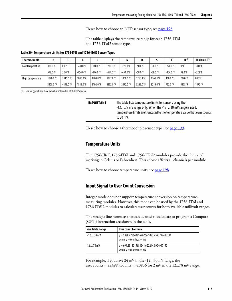
Temperature-measuring Analog Modules (1756-IR6I, 1756-IT6I, and 1756-IT6I2) Chapter 6
To see how to choose an RTD sensor type, see page 198.
The table displays the temperature range for each 1756-IT6Iand 1756-IT6I2 sensor type.
To see how to choose a thermocouple sensor type, see page 199.
Temperature Units
The 1756-IR6I, 1756-IT6I and 1756-IT6I2 modules provide the choice of working in Celsius or Fahrenheit. This choice affects all channels per module.
To see how to choose temperature units, see page 198.
Input Signal to User Count Conversion
Integer mode does not support temperature conversion on temperature-measuring modules. However, this mode can be used by the 1756-IT6I and 1756-IT6I2 modules to calculate user counts for both available millivolt ranges.
The straight line formulas that can be used to calculate or program a Compute (CPT) instruction are shown in the table.
For example, if you have 24 mV in the -12…30 mV range, theuser counts = 22498. Counts = -20856 for 2 mV in the 12…78 mV range.
Table 20 - Temperature Limits for 1756-IT6I and 1756-IT6I2 Sensor Types
Thermocouple B C E J K N R S T D(1) TXK/XK (L)(1)
Low temperature 300.0 °C
572.0 °F
0.0 °LC
32.0 °F
-270.0 °C
-454.0 °F
-210.0 °C
-346.0 °F
-270.0 °C
-454.0 °F
-270.0 °C
-454.0 °F
-50.0 °C
-58.0 °F
-50.0 °C
-58.0 °F
-270.0 °C
-454.0 °F
0 °C
32.0 °F
-200 °C
-328 °F
High temperature 1820.0 °C
3308.0 °F
2315.0 °C
4199.0 °F
1000.0 °C
1832.0 °F
1200.0 °C
2192.0 °F
1372.0 °C
2502.0 °F
1300.0 °C
2372.0 °F
1768.1 °C
3215.0 °F
1768.1 °C
3215.0 °F
400.0 °C
752.0 °F
2320 °C
4208 °F
800 °C
1472 °F
(1) Sensor types D and L are available only on the 1756-IT6I2 module.
IMPORTANT The table lists temperature limits for sensors using the-12…78 mV range only. When the -12…30 mV range is used, temperature limits are truncated to the temperature value that corresponds to 30 mV.
Available Range User Count Formula
-12…30 mV y = 1388.4760408167676x-10825.593777483234where y = counts; x = mV
12…78 mV y = 694.2314015688241x-22244.5904917152where y = counts; x = mV
Rockwell Automation Publication 1756-UM009D-EN-P - March 2015 117
Chapter 6 Temperature-measuring Analog Modules (1756-IR6I, 1756-IT6I, and 1756-IT6I2)
For a table with related values, refer to ControlLogix 1756-IT6Iand 1756-IT6I2 mV Input Signal to User Count Conversion, Knowledgebase Technical Note ID 41567.
Wire Length Calculations
The rule for determining the maximum thermocouple lead length without error is that the lead length’s error must be less than half of the module resolution. This error implies no error is observed nor is recalibration required.
The resolution for the 1756-IT6I and 1756-IT6I2 module, respectively, is:
-12…30 mV range = 0.7 uv/bit-12…78 mV range = 1.4 uv/bit
Based on the schematic on page 124, the module leakage per open-wire current is the bias voltage/pull-up resistance = 0.44V / 20 M= 22 nA. Hence, the maximum thermocouple loop resistance is the sum of total loop resistance = both leads.
Using this equation, for the -12…30 mV range the maximum lead resistance is 16 for a maximum of half resolution error (1/2*(0.7uv/bit) / 22 nA).
For the -12…78 mV range, the maximum lead resistance is 32 for a maximum of half resolution error (1/2*(1.4uv/bit) / 22 nA).
For more information, refer to 1756-IT6I and 1756-IT6I2 Thermocouple Lead Length Calculations, Knowledgebase Technical Note ID 59091.
Differences Between the 1756-IT6I and 1756-IT6I2 Modules
The 1756-IT6I and 1756-IT6I2 modules support grounded and ungrounded thermocouples. However, in addition to offering access to two more thermocouple types (D and TXK/XK [L]), the 1756-IT6I2 module offers the following:
• A greater cold-junction compensation accuracy• Improved module accuracy
See page 122 for details.
While the 1756-IT6I module can report cold junction temperature differences between channels as high as 3 °C from the actual temperature, the1756-IT6I2 module, because it has two cold-junction sensors (CJS), reduces the potential cold-junction error from actual temperature to 0.3 °C.
It’s important that you check that the CJS is fitted locally or remotely, and enabled accordingly in the module channel configuration. If the CJS is not fitted or if the sensor wiring leads are incorrect (for example, swapped over at the
118 Rockwell Automation Publication 1756-UM009D-EN-P - March 2015

Temperature-measuring Analog Modules (1756-IR6I, 1756-IT6I, and 1756-IT6I2) Chapter 6
thermocouple cards input), there’s a possibility of a negative or positive temperature fluctuation when the thermocouple sensor is warmed.
The table lists the cold junction error from actual temperature, depending on the type of cold junction compensation that is used.
Cold Junction Compensation
When using the thermocouple (1756-IT6I and 1756-IT6I2) modules, you must account for additional voltage that can alter the input signal. A small voltage generates at the junction of the thermocouple field wires and the screw terminations of an RTB or IFM. This thermoelectric effect alters theinput signal.
To accurately compensate the input signal from your module, you must use a cold junction sensor (CJS) to account for the increased voltage. Because there are differences if you choose to connect sensors via an RTB or IFM, you must configure the module (via RSLogix 5000 software) to work with the type of CJS used in your application.
Connecting a Cold Junction Sensor Via a Removable Terminal Block
When you connect a CJS to your thermocouple module via an RTB, the following occurs, depending on module type:
• The 1756-IT6I module uses one CJS in the middle of the module and estimates temperature deviation elsewhere on the connector.
• The 1756-IT6I2 module uses two CJSs at the top and bottom of the module and calculates temperature at each channel’s input terminals; this usage of multiple sensors results in increased accuracy.
Table 21 - Cold-junction Compensation Types
If you use this module
With this type of cold junction compensation
The cold junction error from actual temperature is
1756-IT6I2 Two cold-junction sensors onan RTB
+/-0.3 °C (0.54 °F)
1756-IT6I2 IFM +/-0.3 °C (0.54 °F)
1756-IT6I One cold-junction sensor onan RTB
+/-3.2 °C (5.76 °F), max(1)
(1) The cold junction error varies for each channel but 3.2 °C (5.76 °F) is the maximum error any channelshows.
1756-IT6I IFM +/-0.3 °C (0.54 °F)
Rockwell Automation Publication 1756-UM009D-EN-P - March 2015 119
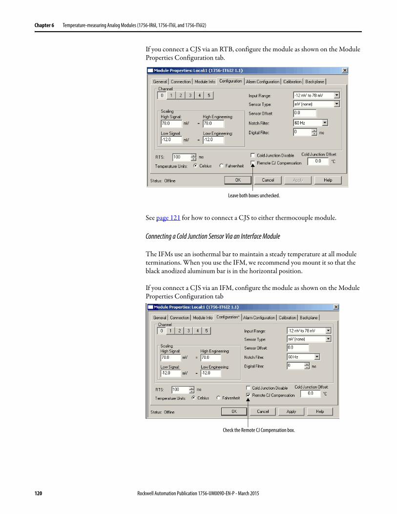
Chapter 6 Temperature-measuring Analog Modules (1756-IR6I, 1756-IT6I, and 1756-IT6I2)
If you connect a CJS via an RTB, configure the module as shown on the Module Properties Configuration tab.
See page 121 for how to connect a CJS to either thermocouple module.
Connecting a Cold Junction Sensor Via an Interface Module
The IFMs use an isothermal bar to maintain a steady temperature at all module terminations. When you use the IFM, we recommend you mount it so that the black anodized aluminum bar is in the horizontal position.
If you connect a CJS via an IFM, configure the module as shown on the Module Properties Configuration tab
Leave both boxes unchecked.
Check the Remote CJ Compensation box.
120 Rockwell Automation Publication 1756-UM009D-EN-P - March 2015
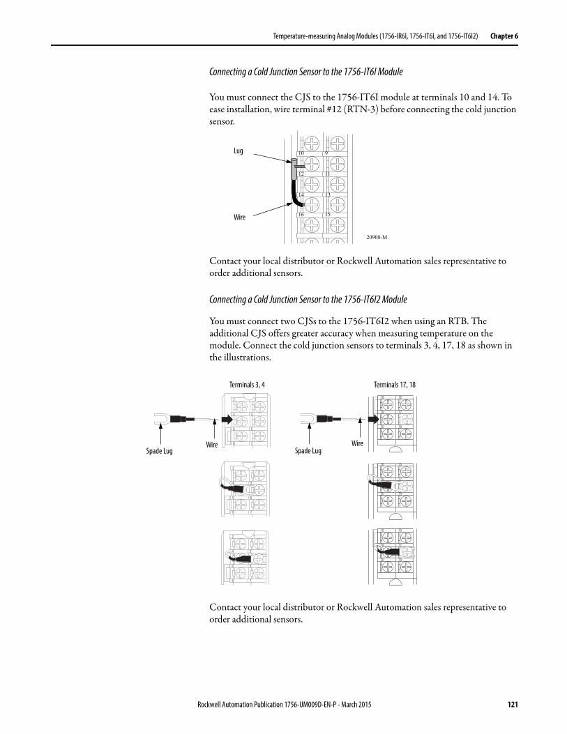
Temperature-measuring Analog Modules (1756-IR6I, 1756-IT6I, and 1756-IT6I2) Chapter 6
Connecting a Cold Junction Sensor to the 1756-IT6I Module
You must connect the CJS to the 1756-IT6I module at terminals 10 and 14. To ease installation, wire terminal #12 (RTN-3) before connecting the cold junction sensor.
Contact your local distributor or Rockwell Automation sales representative to order additional sensors.
Connecting a Cold Junction Sensor to the 1756-IT6I2 Module
You must connect two CJSs to the 1756-IT6I2 when using an RTB. The additional CJS offers greater accuracy when measuring temperature on the module. Connect the cold junction sensors to terminals 3, 4, 17, 18 as shown in the illustrations.
Contact your local distributor or Rockwell Automation sales representative to order additional sensors.
20908-M
10
12
14
16
9
11
13
15
Lug
Wire
16 15
18 17
20 19
16 15
18 17
20 19
16 15
18 17
20 19
2 1
8 7
6 5
4 3
2 1
8 7
6 5
4 3
2 1
8 7
6 5
4 3
Spade LugWire
Spade LugWire
Terminals 3, 4 Terminals 17, 18
Rockwell Automation Publication 1756-UM009D-EN-P - March 2015 121
Chapter 6 Temperature-measuring Analog Modules (1756-IR6I, 1756-IT6I, and 1756-IT6I2)
Cold Junction Disable Option
The Cold Junction Disable box on the Module Properties Configuration tab disables cold junction compensation on all module channels. Typically, this option is used only in systems that have no thermoelectric effect, such as test equipment in a controlled lab.
In most applications, we recommend that you do not use the cold junction disable option.
Cold Junction Offset Option
The Cold Junction Offset box on the Module Properties Configuration Tab lets you make module-wide adjustments to cold junction compensation values. If you know that your cold junction compensation values are consistently inaccurate by some level, for example, 1.2 °C (2.16 °F), you can type the value into the box to account for this inaccuracy.
Improved Module Accuracy
The 1756-IT6I2 offers improved Gain Drift with Temperature and Module Error over Temperature Range specifications when compared to the 1756-IT6I module. The table highlights the differences.
For the latest I/O module specifications, see the 1756 ControlLogix I/O Modules Technical Specifications, publication 1756-TD002.
Cat. No. Gain Drift with Temperature(1)
(1) For a detailed explanation of this specification, see Appendix D.
Module Error over Temperature Range(1)
1756-IT6I 80 ppm 0.5%
1756-IT6I2 25 ppm 0.15%
122 Rockwell Automation Publication 1756-UM009D-EN-P - March 2015
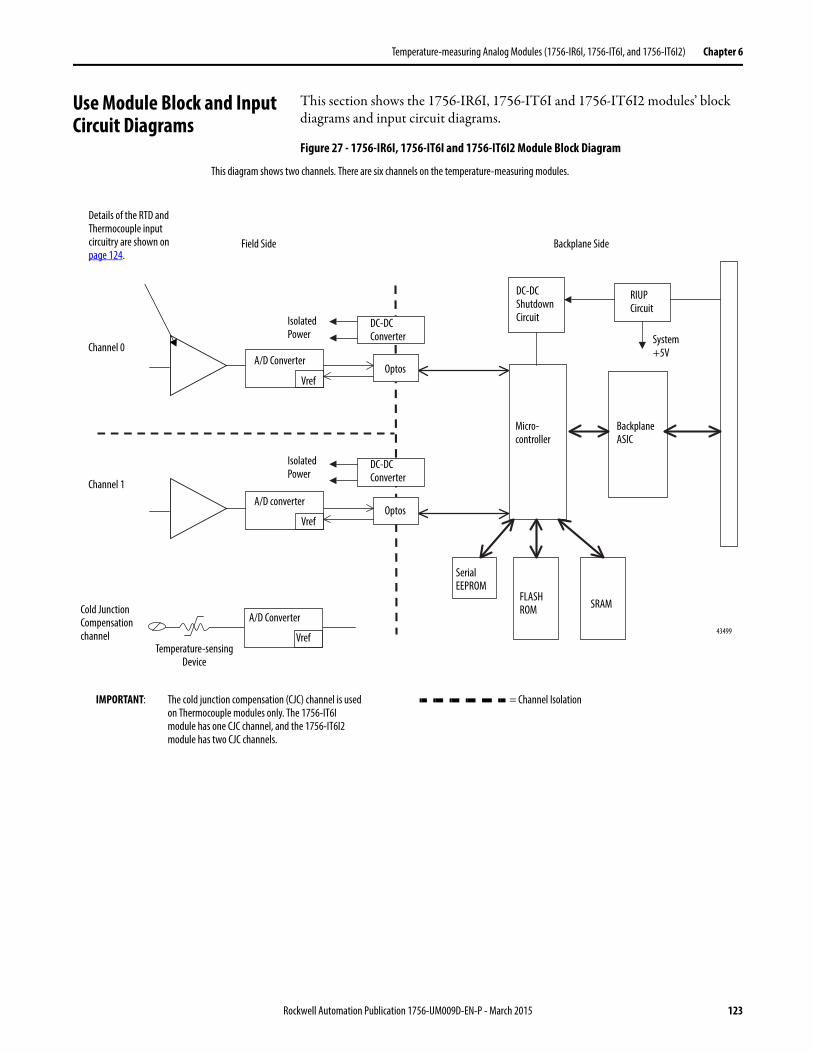
Temperature-measuring Analog Modules (1756-IR6I, 1756-IT6I, and 1756-IT6I2) Chapter 6
Use Module Block and Input Circuit Diagrams
This section shows the 1756-IR6I, 1756-IT6I and 1756-IT6I2 modules’ block diagrams and input circuit diagrams.
Figure 27 - 1756-IR6I, 1756-IT6I and 1756-IT6I2 Module Block Diagram
DC-DC Converter
A/D Converter
RIUP Circuit
43499
DC-DC Converter
VrefOptos
Micro-controller
Backplane ASIC
Serial EEPROM
FLASH ROM SRAM
System +5V
Field Side Backplane Side
DC-DC Shutdown Circuit
Vref
A/D converterOptos
Isolated Power
Details of the RTD and Thermocouple input circuitry are shown on page 124.
Vref
A/D Converter
Temperature-sensing Device
Channel 0
Channel 1
Cold Junction Compensation channel
IMPORTANT: The cold junction compensation (CJC) channel is used on Thermocouple modules only. The 1756-IT6I module has one CJC channel, and the 1756-IT6I2 module has two CJC channels.
This diagram shows two channels. There are six channels on the temperature-measuring modules.
= Channel Isolation
Isolated Power
Rockwell Automation Publication 1756-UM009D-EN-P - March 2015 123
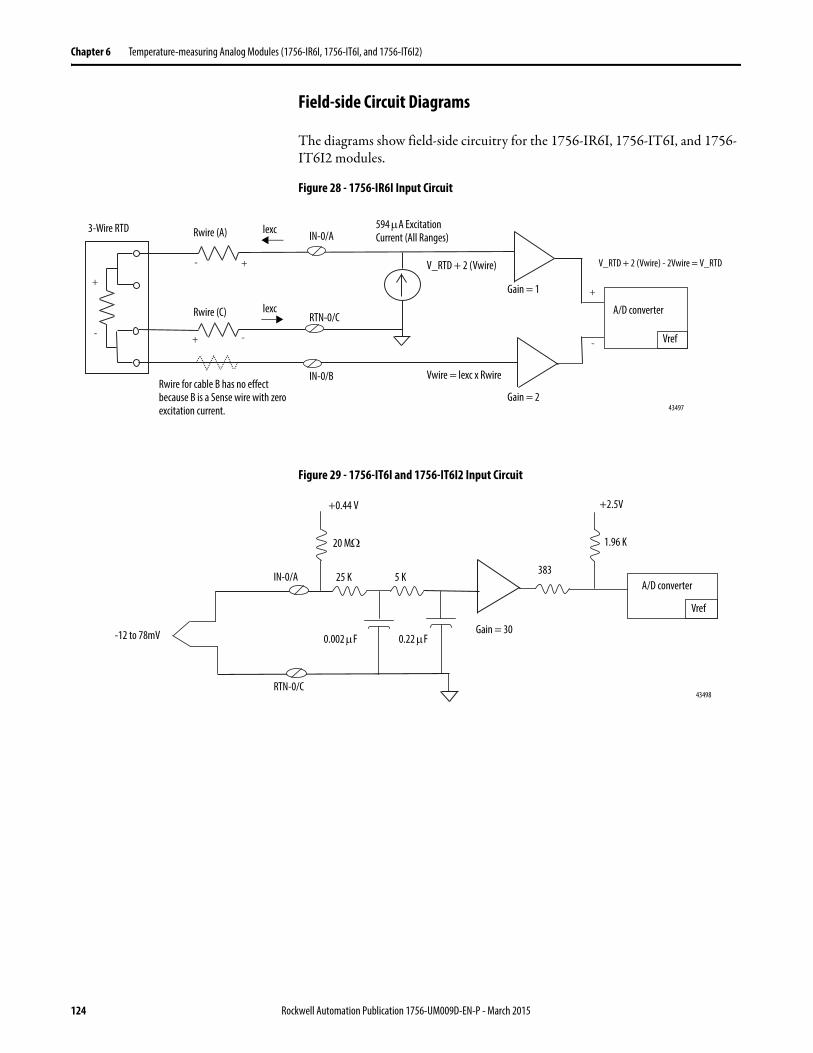
Chapter 6 Temperature-measuring Analog Modules (1756-IR6I, 1756-IT6I, and 1756-IT6I2)
Field-side Circuit Diagrams
The diagrams show field-side circuitry for the 1756-IR6I, 1756-IT6I, and 1756-IT6I2 modules.
Figure 28 - 1756-IR6I Input Circuit
Figure 29 - 1756-IT6I and 1756-IT6I2 Input Circuit
43497
lexc
Rwire (A)
A/D converter
Vref
Gain = 1
IN-0/A
RTN-0/C
V_RTD + 2 (Vwire)
3-Wire RTD
Gain = 2
Rwire (C)
IN-0/B
lexc
Vwire = lexc x Rwire
V_RTD + 2 (Vwire) - 2Vwire = V_RTD
594 A Excitation Current (All Ranges)
Rwire for cable B has no effect because B is a Sense wire with zero excitation current.
43498
IN-0/A
RTN-0/C
+0.44 V
0.22 F
383A/D converter
Vref
0.002 FGain = 30
20 M
25 K 5 K
-12 to 78mV
+2.5V
1.96 K
124 Rockwell Automation Publication 1756-UM009D-EN-P - March 2015
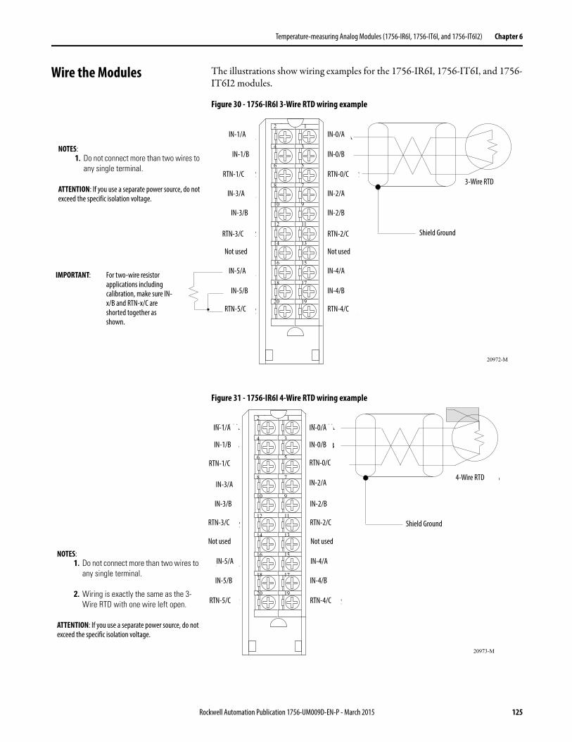
Temperature-measuring Analog Modules (1756-IR6I, 1756-IT6I, and 1756-IT6I2) Chapter 6
Wire the Modules The illustrations show wiring examples for the 1756-IR6I, 1756-IT6I, and 1756-IT6I2 modules.
Figure 30 - 1756-IR6I 3-Wire RTD wiring example
Figure 31 - 1756-IR6I 4-Wire RTD wiring example
20972-M
Shield Ground
IN-0/A
IN-0/B
RTN-0/C
IN-2/A
IN-2/B
RTN-2/C
Not used
IN-4/A
IN-4/B
RTN-4/C
IN-1/A
IN-1/B
RTN-1/C
IN-3/A
IN-3/B
RTN-3/C
Not used
IN-5/A
IN-5/B
RTN-5/C
3-Wire RTD
12
34
56
78
910
1112
1314
1516
1718
1920
IMPORTANT: For two-wire resistor applications including calibration, make sure IN-x/B and RTN-x/C are shorted together as shown.
IN-1/A IN-0/A
IN-1/B
RTN-1/C
IN-3/A
IN-3/B
RTN-3/C
Not used
IN-5/A
IN-5/B
RTN-5/C
IN-0/B
RTN-0/C
IN-2/A
IN-2/B
RTN-2/C
Not used
IN-4/A
IN-4/B
RTN-4/C
Shield Ground
3-Wire RTD
NOTES:1. Do not connect more than two wires to
any single terminal.
ATTENTION: If you use a separate power source, do not exceed the specific isolation voltage.
20973-M
Shield Ground
4-Wire RTD
12
34
56
78
910
1112
1314
1516
1718
1920
IN-0/A
IN-0/B
RTN-0/C
IN-2/A
IN-2/B
RTN-2/C
Not used
IN-4/A
IN-4/B
RTN-4/C
IN-1/A
IN-1/B
RTN-1/C
IN-3/A
IN-3/B
RTN-3/C
Not used
IN-5/A
IN-5/B
RTN-5/C
IN-1/A
IN-1/B
RTN-1/C
IN-3/A
IN-3/B
RTN-3/C
Not used
IN-5/A
IN-5/B
RTN-5/C
IN-0/A
IN-0/B
RTN-0/C
IN-2/A
IN-2/B
RTN-2/C
Not used
IN-4/A
IN-4/B
RTN-4/C
IN-4/A
IN-4/B
4-Wire RTD
Shield Ground
NOTES:1. Do not connect more than two wires to
any single terminal.
2. Wiring is exactly the same as the 3-Wire RTD with one wire left open.
ATTENTION: If you use a separate power source, do not exceed the specific isolation voltage.
Rockwell Automation Publication 1756-UM009D-EN-P - March 2015 125
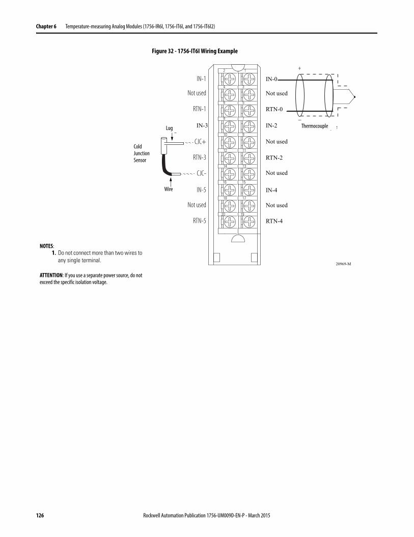
Chapter 6 Temperature-measuring Analog Modules (1756-IR6I, 1756-IT6I, and 1756-IT6I2)
Figure 32 - 1756-IT6I Wiring Example
12
34
56
78
910
1112
1314
1516
1718
1920
+
–
Lug
Wire
20969-M
IN-0
Not used
RTN-0
IN-2
Not used
RTN-2
Not used
IN-4
Not used
RTN-4
IN-1
Not used
RTN-1
IN-3
CJC+
RTN-3
CJC-
IN-5
Not used
RTN-5
Thermocouple
Cold Junction Sensor
Lug
Wire
Thermocouple
NOTES:1. Do not connect more than two wires to
any single terminal.
ATTENTION: If you use a separate power source, do not exceed the specific isolation voltage.
126 Rockwell Automation Publication 1756-UM009D-EN-P - March 2015
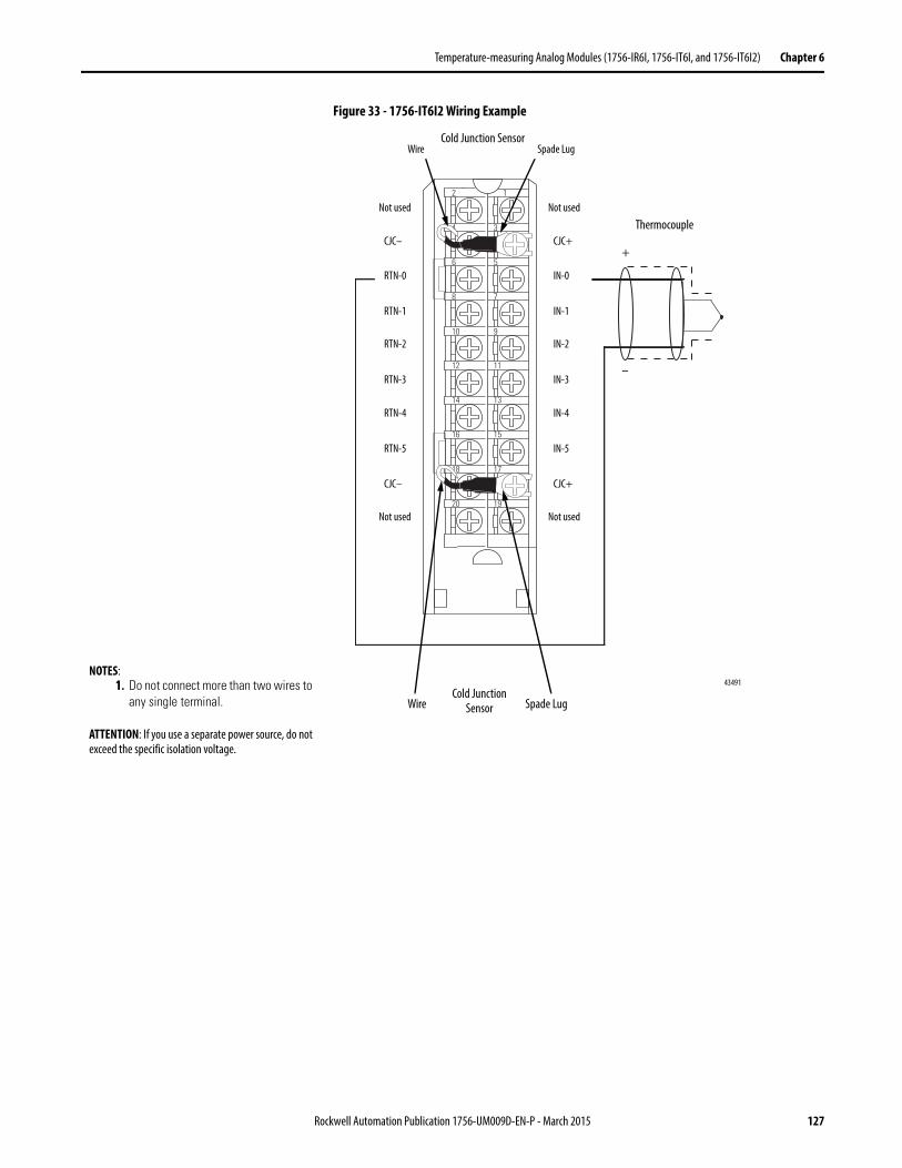
Temperature-measuring Analog Modules (1756-IR6I, 1756-IT6I, and 1756-IT6I2) Chapter 6
Figure 33 - 1756-IT6I2 Wiring Example
+
–
2 1
10 9
8 7
6 5
4 3
12 11
14 13
16 15
18 17
20 19
Cold Junction Sensor
Thermocouple
Wire
Not used
CJC–
RTN-0
RTN-1
RTN-2
RTN-3
RTN-4
RTN-5
CJC–
Not used
Spade Lug
Not used
CJC+
IN-0
IN-1
IN-2
IN-3
IN-4
IN-5
CJC+
Not used
Cold Junction SensorWire Spade Lug
43491
+
–
NOTES:1. Do not connect more than two wires to
any single terminal.
ATTENTION: If you use a separate power source, do not exceed the specific isolation voltage.
Rockwell Automation Publication 1756-UM009D-EN-P - March 2015 127
Chapter 6 Temperature-measuring Analog Modules (1756-IR6I, 1756-IT6I, and 1756-IT6I2)
Fault and Status Reporting The 1756-IR6I, 1756-IT6I, and 1756-IT6I2 modules multicast status and fault data to the owner and/or listening controller with its channel data. The fault data is arranged in such a manner as to let you choose the level of granularity desired for examining fault conditions.
Three levels of tags work together to provide increasing degree of detail as to the specific cause of faults on the module.
The table lists tags that can be examined in ladder logic to indicate when a fault has occurred.
Table 22 - Fault Word Tags
Tag Description
Module Fault Word This word provides fault summary reporting. Its tag name is ModuleFaults.
Channel Fault Word This word provides underrange, overrange, and communication fault reporting. Its tag name is ChannelFaults.
Channel Status Words This word provides individual channel underrange and overrange fault reporting for process alarms, rate alarms, and calibration faults. Its tag name is ChxStatus.
IMPORTANT Differences exist between floating point and integer modes as they relate to module fault reporting. These differences are explained in the following sections.
128 Rockwell Automation Publication 1756-UM009D-EN-P - March 2015
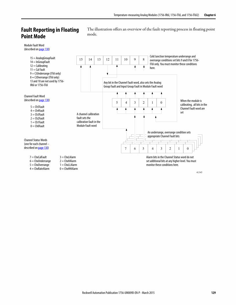
Temperature-measuring Analog Modules (1756-IR6I, 1756-IT6I, and 1756-IT6I2) Chapter 6
Fault Reporting in Floating Point Mode
The illustration offers an overview of the fault reporting process in floating point mode.
Module Fault Word(described on page 130)
Channel Fault Word(described on page 130)
Channel Status Words(one for each channel –described on page 130)
15 14 13 12 11 10 9 8
5 4 3 2 1 0
5 4 3 2 1 07 6
15 = AnalogGroupFault14 = InGroupFault12 = Calibrating11 = Cal Fault9 = CJUnderrange (IT6I only)8 = CJOverrange (IT6I only)13 and 10 are not used by 1756-IR6I or 1756-IT6I
5 = Ch5Fault4 = Ch4Fault3 = Ch3Fault2 = Ch2Fault1 = Ch1Fault0 = Ch0Fault
7 = ChxCalFault6 = ChxUnderrange5 = ChxOverrange4 = ChxRateAlarm
41345
3 = ChxLAlarm2 = ChxHAlarm1 = ChxLLAlarm0 = ChxHHAlarm
Cold Junction temperature underrange and overrange conditions set bits 9 and 8 for 1756-IT6I only. You must monitor these conditions here.
Any bit in the Channel Fault word, also sets the AnalogGroup Fault and Input Group Fault in Module Fault word
A channel calibration fault sets the calibration fault in the Module Fault word
Alarm bits in the Channel Status word do not set additional bits at any higher level. You must monitor these conditions here.
An underrange, overrange condition sets appropriate Channel Fault bits
When the module is calibrating, all bits in the Channel Fault word are set
Rockwell Automation Publication 1756-UM009D-EN-P - March 2015 129
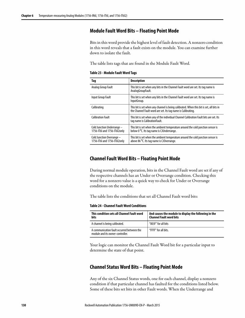
Chapter 6 Temperature-measuring Analog Modules (1756-IR6I, 1756-IT6I, and 1756-IT6I2)
Module Fault Word Bits – Floating Point Mode
Bits in this word provide the highest level of fault detection. A nonzero condition in this word reveals that a fault exists on the module. You can examine further down to isolate the fault.
The table lists tags that are found in the Module Fault Word.
Channel Fault Word Bits – Floating Point Mode
During normal module operation, bits in the Channel Fault word are set if any of the respective channels has an Under or Overrange condition. Checking this word for a nonzero value is a quick way to check for Under or Overrange conditions on the module.
The table lists the conditions that set all Channel Fault word bits:
Your logic can monitor the Channel Fault Word bit for a particular input to determine the state of that point.
Channel Status Word Bits – Floating Point Mode
Any of the six Channel Status words, one for each channel, display a nonzero condition if that particular channel has faulted for the conditions listed below. Some of these bits set bits in other Fault words. When the Underrange and
Table 23 - Module Fault Word Tags
Tag Description
Analog Group Fault This bit is set when any bits in the Channel Fault word are set. Its tag name is AnalogGroupFault.
Input Group Fault This bit is set when any bits in the Channel Fault word are set. Its tag name is InputGroup.
Calibrating This bit is set when any channel is being calibrated. When this bit is set, all bits in the Channel Fault word are set. Its tag name is Calibrating.
Calibration Fault This bit is set when any of the individual Channel Calibration Fault bits are set. Its tag name is CalibrationFault.
Cold Junction Underrange – 1756-IT6I and 1756-IT6I2only
This bit is set when the ambient temperature around the cold junction sensor is below 0 oC. Its tag name is CJUnderrange.
Cold Junction Overrange – 1756-IT6I and 1756-IT6I2only
This bit is set when the ambient temperature around the cold junction sensor is above 86 oC. Its tag name is CJOverrange.
Table 24 - Channel Fault Word Conditions
This condition sets all Channel Fault word bits
And causes the module to display the following in the Channel Fault word bits
A channel is being calibrated. “003F” for all bits
A communication fault occurred between the module and its owner-controller.
“FFFF” for all bits.
130 Rockwell Automation Publication 1756-UM009D-EN-P - March 2015
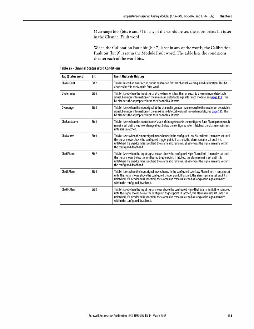
Temperature-measuring Analog Modules (1756-IR6I, 1756-IT6I, and 1756-IT6I2) Chapter 6
Overrange bits (bits 6 and 5) in any of the words are set, the appropriate bit is set in the Channel Fault word.
When the Calibration Fault bit (bit 7) is set in any of the words, the Calibration Fault bit (bit 9) is set in the Module Fault word. The table lists the conditions that set each of the word bits.
Table 25 - Channel Status Word Conditions
Tag (Status word) Bit Event that sets this tag
ChxCalFault Bit 7 This bit is set if an error occurs during calibration for that channel, causing a bad calibration. This bit also sets bit 9 in the Module Fault word.
Underrange Bit 6 This bit is set when the input signal at the channel is less than or equal to the minimum detectable signal. For more information on the minimum detectable signal for each module, see page 111. This bit also sets the appropriate bit in the Channel Fault word.
Overrange Bit 5 This bit is set when the input signal at the channel is greater than or equal to the maximum detectable signal. For more information on the maximum detectable signal for each module, see page 111. This bit also sets the appropriate bit in the Channel Fault word.
ChxRateAlarm Bit 4 This bit is set when the input channel’s rate of change exceeds the configured Rate Alarm parameter. It remains set until the rate of change drops below the configured rate. If latched, the alarm remains set until it is unlatched.
ChxLAlarm BIt 3 This bit is set when the input signal moves beneath the configured Low Alarm limit. It remains set until the signal moves above the configured trigger point. If latched, the alarm remains set until it is unlatched. If a deadband is specified, the alarm also remains set as long as the signal remains within the configured deadband.
ChxHAlarm Bit 2 This bit is set when the input signal moves above the configured High Alarm limit. It remains set until the signal moves below the configured trigger point. If latched, the alarm remains set until it is unlatched. If a deadband is specified, the alarm also remains set as long as the signal remains within the configured deadband.
ChxLLAlarm Bit 1 This bit is set when the input signal moves beneath the configured Low-Low Alarm limit. It remains set until the signal moves above the configured trigger point. If latched, the alarm remains set until it is unlatched. If a deadband is specified, the alarm also remains latched as long as the signal remains within the configured deadband.
ChxHHAlarm Bit 0 This bit is set when the input signal moves above the configured High-High Alarm limit. It remains set until the signal moves below the configured trigger point. If latched, the alarm remains set until it is unlatched. If a deadband is specified, the alarm also remains latched as long as the signal remains within the configured deadband.
Rockwell Automation Publication 1756-UM009D-EN-P - March 2015 131
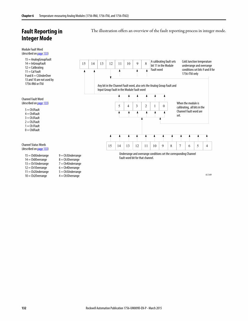
Chapter 6 Temperature-measuring Analog Modules (1756-IR6I, 1756-IT6I, and 1756-IT6I2)
Fault Reporting inInteger Mode
The illustration offers an overview of the fault reporting process in integer mode.
15 14 13 12 11 10 9 8
5 4 3 2 1 0
5 49 8 7 6
15 = AnalogGroupFault14 = InGroupFault12 = Calibrating11 = Cal Fault9 and 8 = CJUnderOver13 and 10 are not used by 1756-IR6I or IT6I
5 = Ch5Fault4 = Ch4Fault3 = Ch3Fault2 = Ch2Fault1 = Ch1Fault0 = Ch0Fault
15 = Ch0Underrange14 = Ch0Overrange13 = Ch1Underrange12 = Ch1Overrange11 = Ch2Underrange10 = Ch2Overrange 41349
15 14 13 12 11 10
9 = Ch3Underrange8 = Ch3Overrange7 = Ch4Underrange6 = Ch4Overrange5 = Ch5Underrange4 = Ch5Overrange
Underrange and overrange conditions set the corresponding Channel Fault word bit for that channel.
When the module is calibrating, all bits in the Channel Fault word are set.
Any bit in the Channel Fault word, also sets the Analog Group Fault and Input Group Fault in the Module Fault word
A calibrating fault sets bit 11 in the Module Fault word
Cold Junction temperature underrange and overrange conditions set bits 9 and 8 for 1756-IT6I only
Module Fault Word(described on page 133)
Channel Fault Word(described on page 133)
Channel Status Words(described on page 133)
132 Rockwell Automation Publication 1756-UM009D-EN-P - March 2015
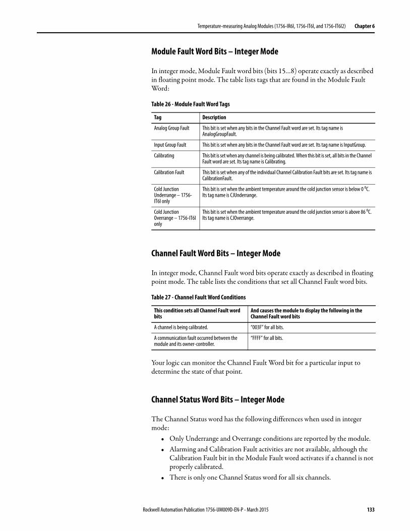
Temperature-measuring Analog Modules (1756-IR6I, 1756-IT6I, and 1756-IT6I2) Chapter 6
Module Fault Word Bits – Integer Mode
In integer mode, Module Fault word bits (bits 15…8) operate exactly as described in floating point mode. The table lists tags that are found in the Module Fault Word:
Channel Fault Word Bits – Integer Mode
In integer mode, Channel Fault word bits operate exactly as described in floating point mode. The table lists the conditions that set all Channel Fault word bits.
Your logic can monitor the Channel Fault Word bit for a particular input to determine the state of that point.
Channel Status Word Bits – Integer Mode
The Channel Status word has the following differences when used in integer mode:
• Only Underrange and Overrange conditions are reported by the module.• Alarming and Calibration Fault activities are not available, although the
Calibration Fault bit in the Module Fault word activates if a channel is not properly calibrated.
• There is only one Channel Status word for all six channels.
Table 26 - Module Fault Word Tags
Tag Description
Analog Group Fault This bit is set when any bits in the Channel Fault word are set. Its tag name is AnalogGroupFault.
Input Group Fault This bit is set when any bits in the Channel Fault word are set. Its tag name is InputGroup.
Calibrating This bit is set when any channel is being calibrated. When this bit is set, all bits in the Channel Fault word are set. Its tag name is Calibrating.
Calibration Fault This bit is set when any of the individual Channel Calibration Fault bits are set. Its tag name is CalibrationFault.
Cold Junction Underrange – 1756-IT6I only
This bit is set when the ambient temperature around the cold junction sensor is below 0 oC. Its tag name is CJUnderrange.
Cold Junction Overrange – 1756-IT6I only
This bit is set when the ambient temperature around the cold junction sensor is above 86 oC. Its tag name is CJOverrange.
Table 27 - Channel Fault Word Conditions
This condition sets all Channel Fault word bits
And causes the module to display the following in the Channel Fault word bits
A channel is being calibrated. “003F” for all bits.
A communication fault occurred between the module and its owner-controller.
“FFFF” for all bits.
Rockwell Automation Publication 1756-UM009D-EN-P - March 2015 133
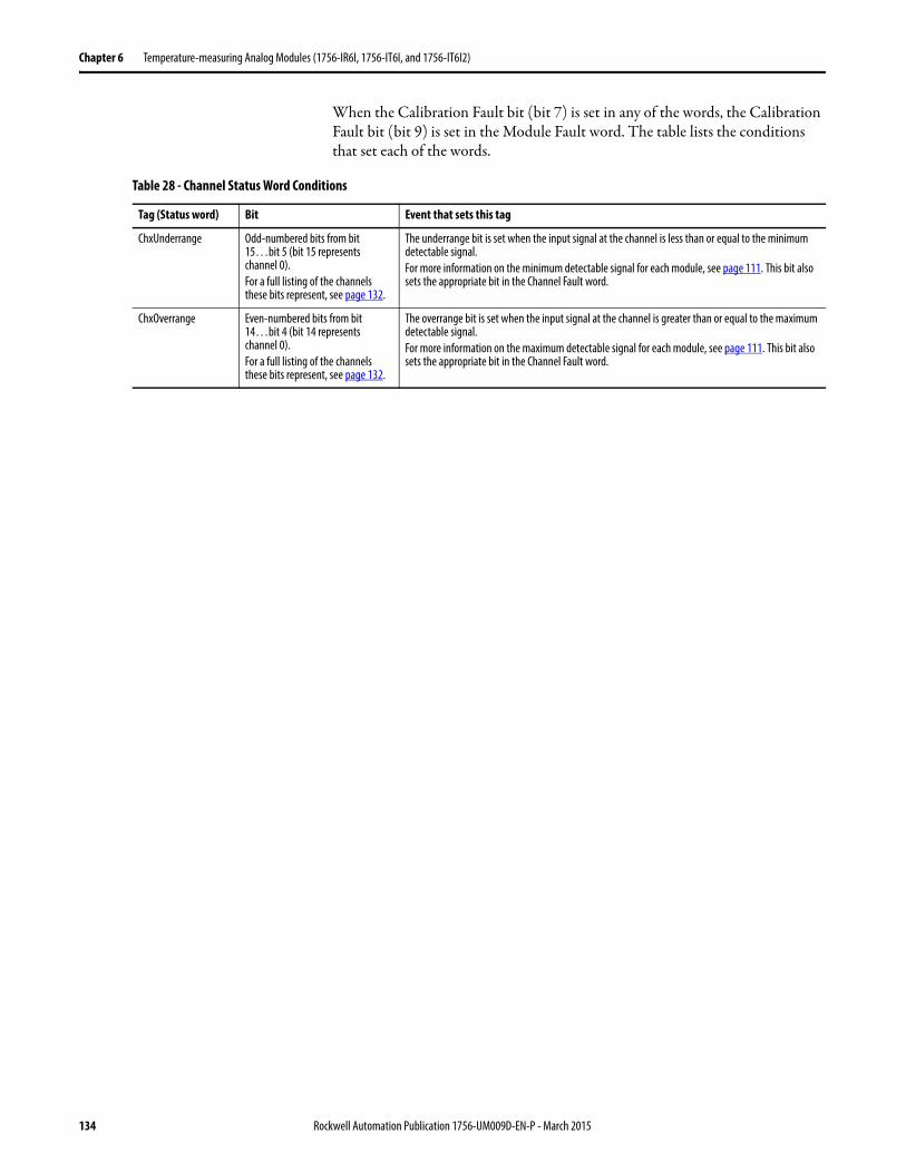
Chapter 6 Temperature-measuring Analog Modules (1756-IR6I, 1756-IT6I, and 1756-IT6I2)
When the Calibration Fault bit (bit 7) is set in any of the words, the Calibration Fault bit (bit 9) is set in the Module Fault word. The table lists the conditions that set each of the words.
Table 28 - Channel Status Word Conditions
Tag (Status word) Bit Event that sets this tag
ChxUnderrange Odd-numbered bits from bit 15…bit 5 (bit 15 represents channel 0).For a full listing of the channels these bits represent, see page 132.
The underrange bit is set when the input signal at the channel is less than or equal to the minimum detectable signal.For more information on the minimum detectable signal for each module, see page 111. This bit also sets the appropriate bit in the Channel Fault word.
ChxOverrange Even-numbered bits from bit 14…bit 4 (bit 14 represents channel 0).For a full listing of the channels these bits represent, see page 132.
The overrange bit is set when the input signal at the channel is greater than or equal to the maximum detectable signal.For more information on the maximum detectable signal for each module, see page 111. This bit also sets the appropriate bit in the Channel Fault word.
134 Rockwell Automation Publication 1756-UM009D-EN-P - March 2015
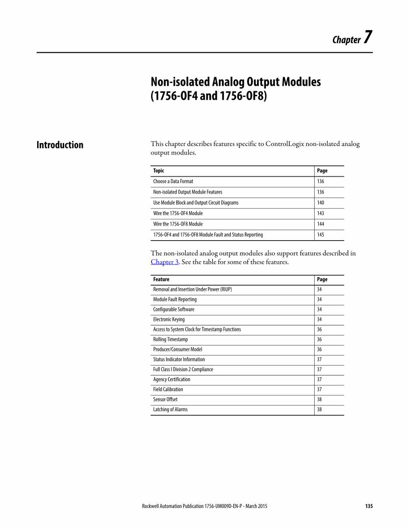
Chapter 7
Non-isolated Analog Output Modules (1756-OF4 and 1756-OF8)
Introduction This chapter describes features specific to ControlLogix non-isolated analog output modules.
The non-isolated analog output modules also support features described in Chapter 3. See the table for some of these features.
Topic Page
Choose a Data Format 136
Non-isolated Output Module Features 136
Use Module Block and Output Circuit Diagrams 140
Wire the 1756-OF4 Module 143
Wire the 1756-OF8 Module 144
1756-OF4 and 1756-OF8 Module Fault and Status Reporting 145
Feature Page
Removal and Insertion Under Power (RIUP) 34
Module Fault Reporting 34
Configurable Software 34
Electronic Keying 34
Access to System Clock for Timestamp Functions 36
Rolling Timestamp 36
Producer/Consumer Model 36
Status Indicator Information 37
Full Class I Division 2 Compliance 37
Agency Certification 37
Field Calibration 37
Sensor Offset 38
Latching of Alarms 38
Rockwell Automation Publication 1756-UM009D-EN-P - March 2015 135
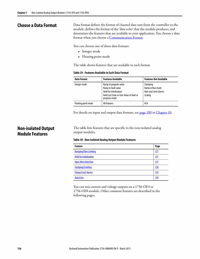
Chapter 7 Non-isolated Analog Output Modules (1756-OF4 and 1756-OF8)
Choose a Data Format Data format defines the format of channel data sent from the controller to the module, defines the format of the ‘data echo’ that the module produces, and determines the features that are available to your application. You choose a data format when you choose a Communication Format.
You can choose one of these data formats:• Integer mode• Floating point mode
The table shows features that are available in each format.
For details on input and output data formats, see page 189 in Chapter 10.
Non-isolated OutputModule Features
The table lists features that are specific to the non-isolated analogoutput modules.
You can mix current and voltage outputs on a 1756-OF4 or 1756-OF8 module. Other common features are described in thefollowing pages.
Table 29 - Features Available in Each Data Format
Data Format Features Available Features Not Available
Integer mode Ramp to program valueRamp to fault valueHold for initializationHold Last State or User Value in fault or program mode
ClampingRamp in Run modeRate and Limit alarmsScaling
Floating point mode All features N/A
Table 30 - Non-isolated Analog Output Module Features
Feature Page
Ramping/Rate Limiting 137
Hold for Initialization 137
Open Wire Detection 137
Clamping/Limiting 138
Clamp/Limit Alarms 139
Data Echo 139
136 Rockwell Automation Publication 1756-UM009D-EN-P - March 2015
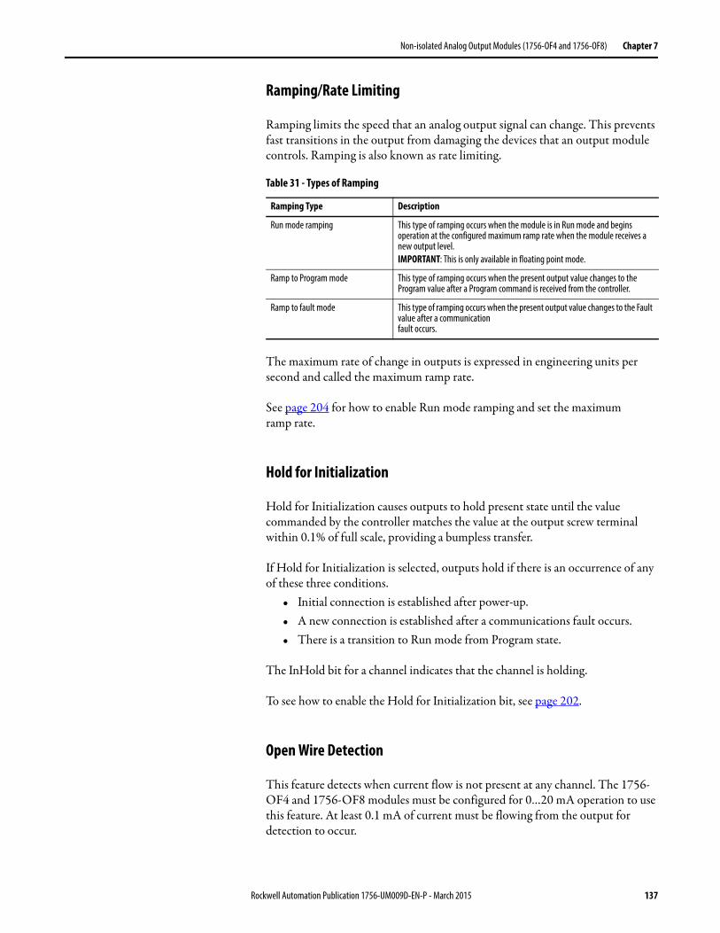
Non-isolated Analog Output Modules (1756-OF4 and 1756-OF8) Chapter 7
Ramping/Rate Limiting
Ramping limits the speed that an analog output signal can change. This prevents fast transitions in the output from damaging the devices that an output module controls. Ramping is also known as rate limiting.
The maximum rate of change in outputs is expressed in engineering units per second and called the maximum ramp rate.
See page 204 for how to enable Run mode ramping and set the maximumramp rate.
Hold for Initialization
Hold for Initialization causes outputs to hold present state until the value commanded by the controller matches the value at the output screw terminal within 0.1% of full scale, providing a bumpless transfer.
If Hold for Initialization is selected, outputs hold if there is an occurrence of any of these three conditions.
• Initial connection is established after power-up.• A new connection is established after a communications fault occurs.• There is a transition to Run mode from Program state.
The InHold bit for a channel indicates that the channel is holding.
To see how to enable the Hold for Initialization bit, see page 202.
Open Wire Detection
This feature detects when current flow is not present at any channel. The 1756-OF4 and 1756-OF8 modules must be configured for 0…20 mA operation to use this feature. At least 0.1 mA of current must be flowing from the output for detection to occur.
Table 31 - Types of Ramping
Ramping Type Description
Run mode ramping This type of ramping occurs when the module is in Run mode and begins operation at the configured maximum ramp rate when the module receives a new output level.IMPORTANT: This is only available in floating point mode.
Ramp to Program mode This type of ramping occurs when the present output value changes to the Program value after a Program command is received from the controller.
Ramp to fault mode This type of ramping occurs when the present output value changes to the Fault value after a communicationfault occurs.
Rockwell Automation Publication 1756-UM009D-EN-P - March 2015 137
Chapter 7 Non-isolated Analog Output Modules (1756-OF4 and 1756-OF8)
When an open wire condition occurs at any channel, a status bit is set forthat channel.
For more information on the use of status bits, see page 145.
Clamping/Limiting
Clamping limits the output from the analog module to remain within a range configured by the controller, even when the controller commands an output outside that range. This safety feature sets a high clamp and a low clamp.
Once clamps are determined for a module, any data received from the controller that exceeds those clamps sets an appropriate limit alarm and transitions the output to that limit but not beyond the requested value.
For example, an application sets the high clamp on a module for 8V and the low clamp for -8V. If a controller sends a value corresponding to 9V to the module, the module only applies 8V to its screw terminals.
Clamping alarms can be disabled or latched on a per channel basis.
To see how to set the clamping limits, see page 204.
IMPORTANT Clamping is only available in floating point mode.Clamp values are in engineering scaling units and are not automatically updated when the engineering high and low scaling units are changed. Failure to update the clamp values generates a very small output signal that could be misinterpreted as a hardware problem.
138 Rockwell Automation Publication 1756-UM009D-EN-P - March 2015
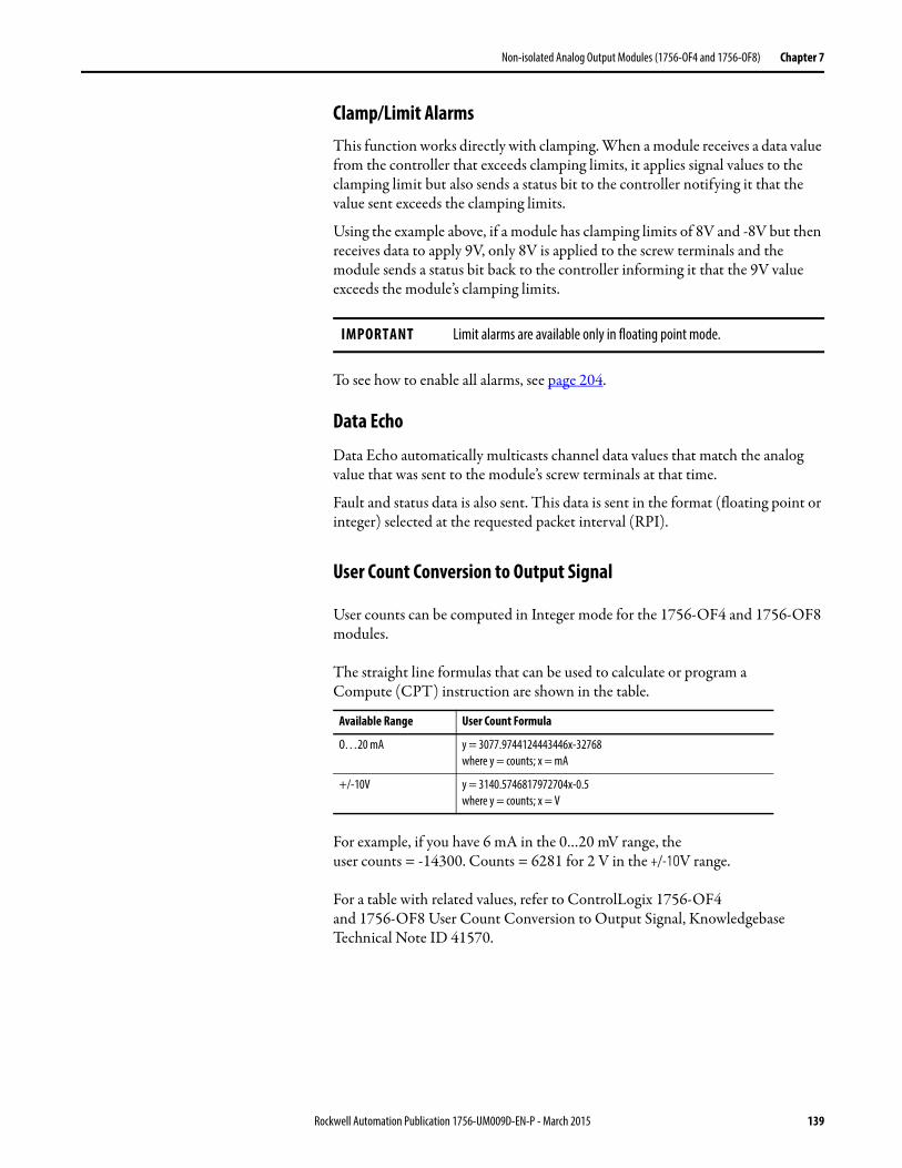
Non-isolated Analog Output Modules (1756-OF4 and 1756-OF8) Chapter 7
Clamp/Limit AlarmsThis function works directly with clamping. When a module receives a data value from the controller that exceeds clamping limits, it applies signal values to the clamping limit but also sends a status bit to the controller notifying it that the value sent exceeds the clamping limits.
Using the example above, if a module has clamping limits of 8V and -8V but then receives data to apply 9V, only 8V is applied to the screw terminals and the module sends a status bit back to the controller informing it that the 9V value exceeds the module’s clamping limits.
To see how to enable all alarms, see page 204.
Data Echo
Data Echo automatically multicasts channel data values that match the analog value that was sent to the module’s screw terminals at that time.
Fault and status data is also sent. This data is sent in the format (floating point or integer) selected at the requested packet interval (RPI).
User Count Conversion to Output Signal
User counts can be computed in Integer mode for the 1756-OF4 and 1756-OF8 modules.
The straight line formulas that can be used to calculate or program aCompute (CPT) instruction are shown in the table.
For example, if you have 6 mA in the 0…20 mV range, theuser counts = -14300. Counts = 6281 for 2 V in the +/-10V range.
For a table with related values, refer to ControlLogix 1756-OF4and 1756-OF8 User Count Conversion to Output Signal, Knowledgebase Technical Note ID 41570.
IMPORTANT Limit alarms are available only in floating point mode.
Available Range User Count Formula
O…20 mA y = 3077.9744124443446x-32768where y = counts; x = mA
+/-10V y = 3140.5746817972704x-0.5where y = counts; x = V
Rockwell Automation Publication 1756-UM009D-EN-P - March 2015 139
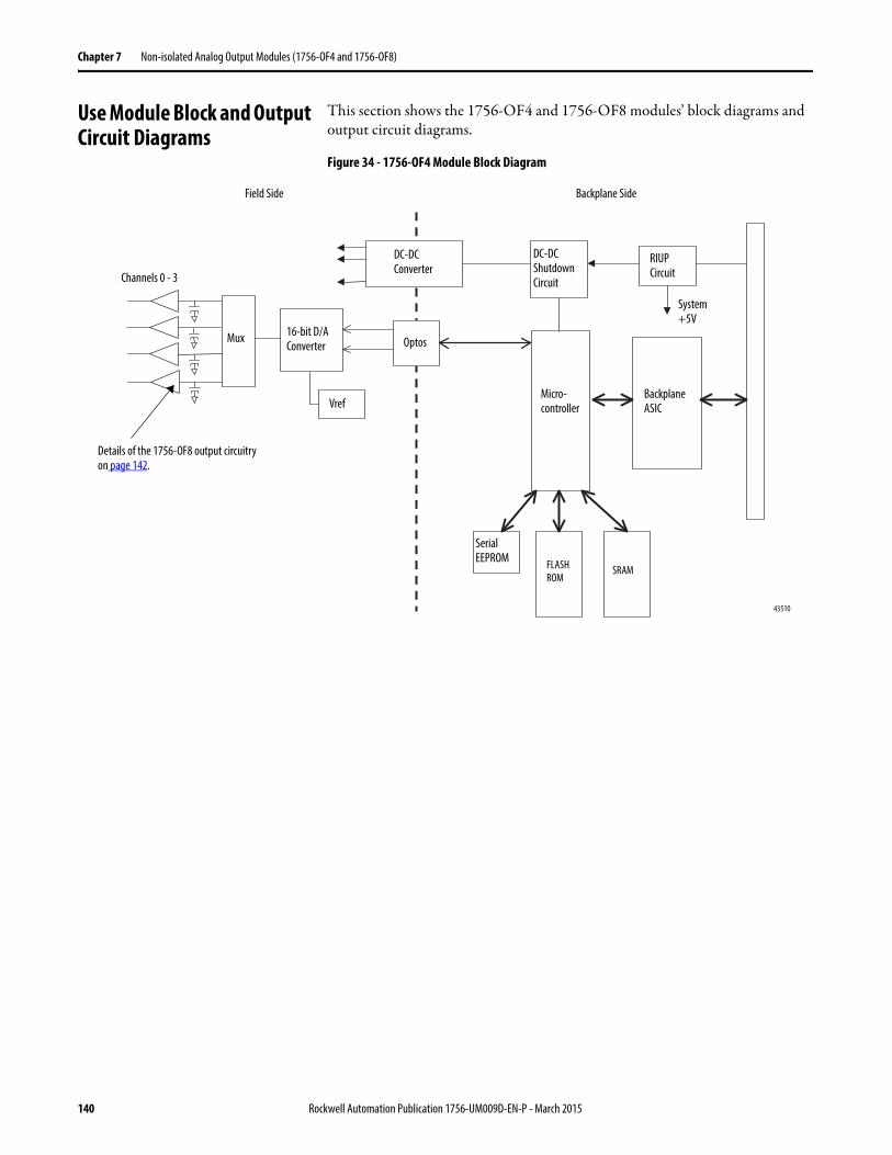
Chapter 7 Non-isolated Analog Output Modules (1756-OF4 and 1756-OF8)
Use Module Block and Output Circuit Diagrams
This section shows the 1756-OF4 and 1756-OF8 modules’ block diagrams and output circuit diagrams.
Figure 34 - 1756-OF4 Module Block Diagram
DC-DC Converter
16-bit D/A Converter
RIUP Circuit
43510
Vref
Optos
Micro-controller
Serial EEPROM FLASH
ROMSRAM
System +5V
Field Side Backplane Side
DC-DC Shutdown CircuitChannels 0 - 3
Details of the 1756-OF8 output circuitry on page 142.
Mux
Backplane ASIC
140 Rockwell Automation Publication 1756-UM009D-EN-P - March 2015
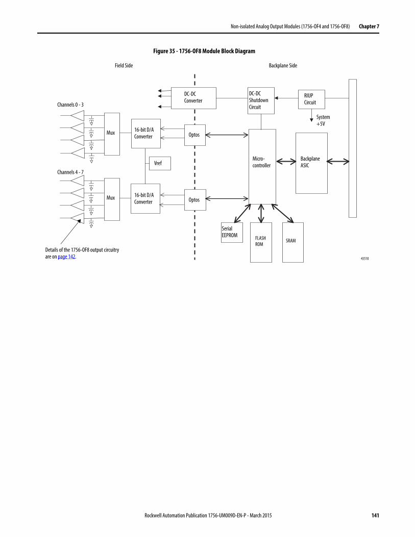
Non-isolated Analog Output Modules (1756-OF4 and 1756-OF8) Chapter 7
Figure 35 - 1756-OF8 Module Block Diagram
DC-DC Converter
16-bit D/A Converter
RIUP Circuit
43510
16-bit D/A Converter
Vref
Optos
Micro-controller
FLASH ROM
SRAM
System +5V
Field Side Backplane Side
DC-DC Shutdown CircuitChannels 0 - 3
Channels 4 - 7
Details of the 1756-OF8 output circuitry are on page 142.
Optos
Mux
Mux
Backplane ASIC
Serial EEPROM
Rockwell Automation Publication 1756-UM009D-EN-P - March 2015 141
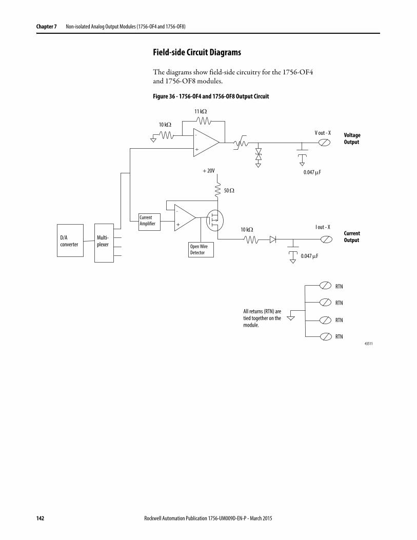
Chapter 7 Non-isolated Analog Output Modules (1756-OF4 and 1756-OF8)
Field-side Circuit Diagrams
The diagrams show field-side circuitry for the 1756-OF4and 1756-OF8 modules.
Figure 36 - 1756-OF4 and 1756-OF8 Output Circuit
43511
RTN
+ 20V
10 k
I out - X
D/A converter
Current Amplifier
0.047 F
Multi-plexer
RTN
RTN
RTN
10 k
Open Wire Detector
All returns (RTN) are tied together on the module.
V out - X
0.047 F
11 k
Voltage Output
Current Output
50
142 Rockwell Automation Publication 1756-UM009D-EN-P - March 2015
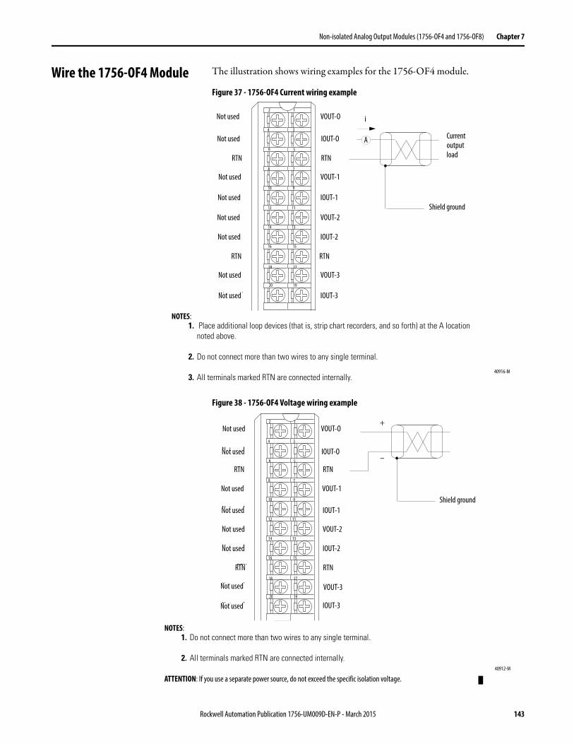
Non-isolated Analog Output Modules (1756-OF4 and 1756-OF8) Chapter 7
Wire the 1756-OF4 Module The illustration shows wiring examples for the 1756-OF4 module.
Figure 37 - 1756-OF4 Current wiring example
Figure 38 - 1756-OF4 Voltage wiring example
VOUT-2
IOUT-2
RTN
VOUT-3
IOUT-3
VOUT-0
IOUT-0
RTN
VOUT-1
IOUT-1
12
34
56
78
910
1112
1314
1516
1718
1920
i
Not used
Not used
RTN
Not used
Not used
RTN
Not used
Not used
A
NOTES:1. Place additional loop devices (that is, strip chart recorders, and so forth) at the A location
noted above.
2. Do not connect more than two wires to any single terminal.
3. All terminals marked RTN are connected internally.
Not used
Not used
Current output load
Shield ground
40916-M
Not used
Not used
RTN
Not used
Not used
Not used
Not used
RTN
Not used
Not used
VOUT-O
IOUT-O
RTN
VOUT-1
IOUT-1
VOUT-2
IOUT-2
RTN
VOUT-3
IOUT-3
VOUT-2
IOUT-2
RTN
VOUT-3
IOUT-3
VOUT-0
IOUT-0
RTN
VOUT-1
IOUT-1
12
34
56
78
910
1112
1314
1516
1718
1920
+
–
Not used
Not used
RTN
Not used
Not used
RTN
Not used
Not used
NOTES:1. Do not connect more than two wires to any single terminal.
2. All terminals marked RTN are connected internally.
ATTENTION: If you use a separate power source, do not exceed the specific isolation voltage.
Not used
Not used
Shield ground
40912-M
Not used
Not used
Not used
Not used
Not used
Not used
Not used
Not used
RTN
RTN RTN
RTN
VOUT-O
IOUT-O
VOUT-1
IOUT-1
VOUT-2
IOUT-2
VOUT-3
IOUT-3
Rockwell Automation Publication 1756-UM009D-EN-P - March 2015 143
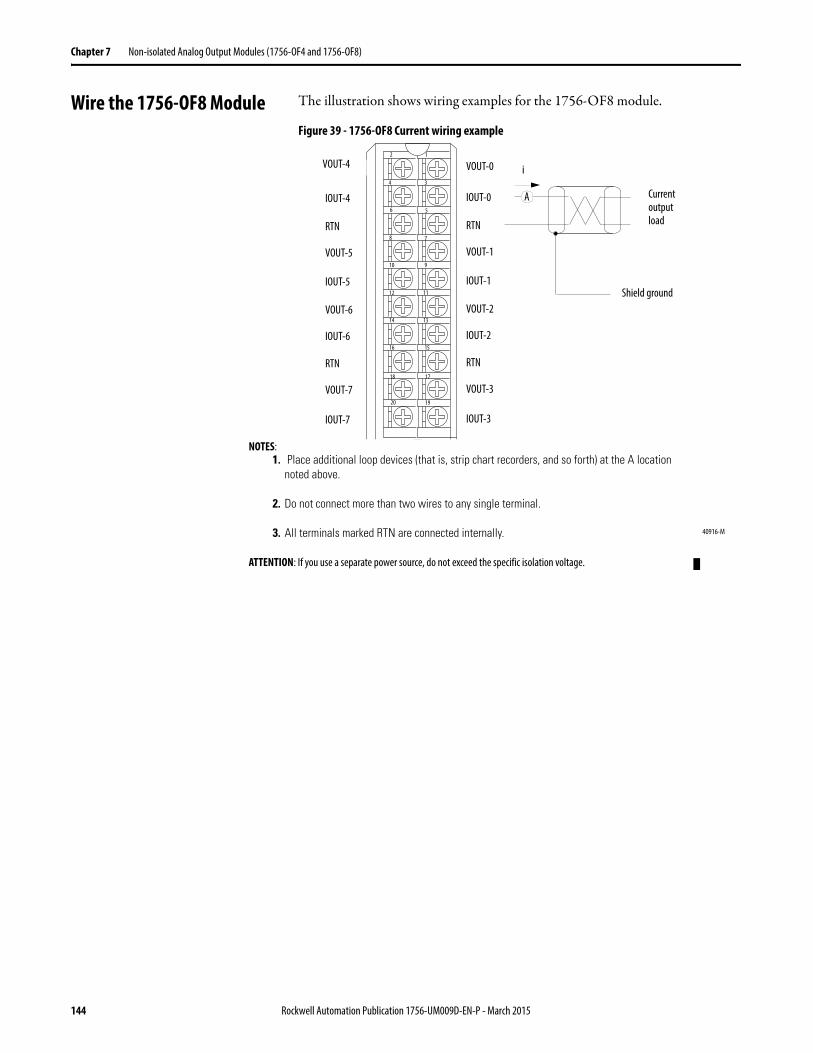
Chapter 7 Non-isolated Analog Output Modules (1756-OF4 and 1756-OF8)
Wire the 1756-OF8 Module The illustration shows wiring examples for the 1756-OF8 module.
Figure 39 - 1756-OF8 Current wiring example
VOUT-2
IOUT-2
RTN
VOUT-3
IOUT-3
VOUT-0
IOUT-0
RTN
VOUT-1
IOUT-1
12
34
56
78
910
1112
1314
1516
1718
1920
VOUT-6
IOUT-6
RTN
VOUT-7
IOUT-7
VOUT-4
IOUT-4
RTN
VOUT-5
IOUT-5
i
A
NOTES:1. Place additional loop devices (that is, strip chart recorders, and so forth) at the A location
noted above.
2. Do not connect more than two wires to any single terminal.
3. All terminals marked RTN are connected internally.
ATTENTION: If you use a separate power source, do not exceed the specific isolation voltage.
Current output load
Shield ground
40916-M
VOUT-4
144 Rockwell Automation Publication 1756-UM009D-EN-P - March 2015
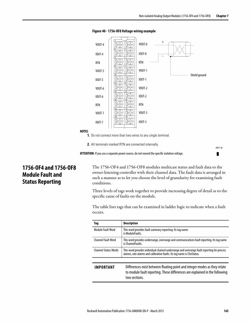
Non-isolated Analog Output Modules (1756-OF4 and 1756-OF8) Chapter 7
Figure 40 - 1756-OF8 Voltage wiring example
1756-OF4 and 1756-OF8 Module Fault and Status Reporting
The 1756-OF4 and 1756-OF8 modules multicast status and fault data to the owner-listening controller with their channel data. The fault data is arranged in such a manner as to let you choose the level of granularity for examining fault conditions.
Three levels of tags work together to provide increasing degree of detail as to the specific cause of faults on the module.
The table lists tags that can be examined in ladder logic to indicate when a fault occurs.
VOUT-2
IOUT-2
RTN
VOUT-3
IOUT-3
VOUT-0
IOUT-0
RTN
VOUT-1
IOUT-1
12
34
56
78
910
1112
1314
1516
1718
1920
VOUT-6
IOUT-6
RTN
VOUT-7
IOUT-7
VOUT-4
IOUT-4
RTN
VOUT-5
IOUT-5
+
–
NOTES:1. Do not connect more than two wires to any single terminal.
2. All terminals marked RTN are connected internally.
ATTENTION: If you use a separate power source, do not exceed the specific isolation voltage.
40917-M
Shield ground
Tag Description
Module Fault Word This word provides fault summary reporting. Its tag nameis ModuleFaults.
Channel Fault Word This word provides underrange, overrange and communications fault reporting. Its tag name is ChannelFaults.
Channel Status Words This word provides individual channel underrange and overrange fault reporting for process alarms, rate alarms and calibration faults. Its tag name is ChxStatus.
IMPORTANT Differences exist between floating point and integer modes as they relate to module fault reporting. These differences are explained in the following two sections.
Rockwell Automation Publication 1756-UM009D-EN-P - March 2015 145
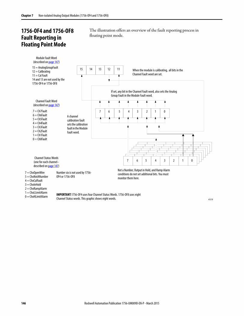
Chapter 7 Non-isolated Analog Output Modules (1756-OF4 and 1756-OF8)
1756-OF4 and 1756-OF8Fault Reporting inFloating Point Mode
The illustration offers an overview of the fault reporting process infloating point mode.
Module Fault Word(described on page 147)
Channel Fault Word(described on page 147)
Channel Status Words(one for each channel–described on page 147)
15 14 13 12 11
5 4 3 2 1 0
5 4 3 2 1 07 6
15 = AnalogGroupFault12 = Calibrating11 = Cal Fault14 and 13 are not used by the 1756-OF4 or 1756-OF8
7 = Ch7Fault6 = Ch6Fault5 = Ch5Fault4 = Ch4Fault3 = Ch3Fault2 = Ch2Fault1 = Ch1Fault0 = Ch0Fault
7 = ChxOpenWire5 = ChxNotANumber4 = ChxCalFault3 = ChxInHold2 = ChxRampAlarm1 = ChxLLimitAlarm0 = ChxHLimitAlarm
Not a Number, Output in Hold, and Ramp Alarm conditions do not set additional bits. You must monitor them here.
Number six is not used by 1756-OF4 or 1756-OF8
If set, any bit in the Channel Fault word, also sets the Analog Group Fault in the Module Fault word.
A channel calibration fault sets the calibration fault in the Module Fault word.
When the module is calibrating, all bits in the Channel Fault word are set.
IMPORTANT:1756-OF4 uses four Channel Status Words. 1756-OF8 uses eight Channel Status words. This graphic shows eight words.
7 6
41519
146 Rockwell Automation Publication 1756-UM009D-EN-P - March 2015
Non-isolated Analog Output Modules (1756-OF4 and 1756-OF8) Chapter 7
Module Fault Word Bits – Floating Point Mode
Bits in this word provide the highest level of fault detection. A nonzero condition in this word reveals that a fault exists on the module. You can examine further down to isolate the fault.
The table lists tags that are found in the Module Fault Word.
Channel Fault Word Bits – Floating Point Mode
During normal module operation, Channel Fault word bits are set if any of the respective channels has a High or Low Limit Alarm or an Open Wire condition (0…20 mA configuration only). When using the Channel Fault Word, the 1756-OF4 module uses bits 0…3, and the 1756-OF8 uses bits 0…7. Checking this word for a nonzero condition is a quick way to check for these conditions on a channel.
The table lists the conditions that set all Channel Fault word bits.
Set your logic to monitor the Channel Fault bit for a particular output, if you either:
• enable output clamping.• are checking for a open wire condition (0 …20 mA configuration only).
Channel Status Words Bits – Floating Point Mode
Any of the Channel Status words (four words for 1756-OF4 and eight words for 1756-OF8), one for each channel, display a nonzero condition if that particular channel has faulted for the conditions listed below. Some of these bits set bits in other Fault words.
When the High or Low Limit Alarm bits (bits 1 and 0) in any of the words are set, the appropriate bit is set in the Channel Fault word.
Tag Description
Analog Group Fault This bit is set when any bits in the Channel Fault word are set. Its tag name is AnalogGroupFault.
Calibrating This bit is set when any channel is being calibrated. When this bit is set, all bits in the Channel Fault word are set. Its tag name is Calibrating.
Calibration Fault This bit is set when any of the individual Channel Calibration Fault bits are set. Its tag name is CalibrationFault.
This condition sets all Channel Fault word bits
And causes the module to display the following in the Channel Fault word bits
A channel is being calibrated ‘000F’ for all bits on the 1756-OF4 module‘00FF’ for all bits on the 1756-OF8 module
A communications fault occurred between the module and its owner-controller
‘FFFF’ for all bits on either module
Rockwell Automation Publication 1756-UM009D-EN-P - March 2015 147
Chapter 7 Non-isolated Analog Output Modules (1756-OF4 and 1756-OF8)
When the Calibration Fault bit (bit 4) is set in any of the words, the Calibration Fault bit (bit 11) is set in the Module Fault word.
The table lists the conditions that set each of the word bits.
Tag (Status word) Bit Event that sets this tag
ChxOpenWire Bit 7 This bit is set only if the configured Output Range is 0…20 mA, and the circuit becomes open due to a wire falling or being cut when the output being driven is above 0.1 mA. The bit remains set until correct wiring is restored.
ChxNotaNumber Bit 5 This bit is set when the output value received from the controller is NotANumber (the IEEE NAN value). The output channel holds its last state.
ChxCalFault Bit 4 This bit is set when an error occurred when calibrating. This bit also sets the appropriate bit in the Channel Fault word.
ChxInHold BIt 3 This bit is set when the output channel is currently holding. The bit resets when the requested Run mode output value is within 0.1% of full-scale of the current echo value.
ChxRampAlarm Bit 2 This bit is set when the output channel’s requested rate of change would exceed the configured maximum ramp rate requested parameter. It remains set until the output reaches its target value and ramping stops. If the bit is latched, it remains set until it is unlatched.
ChxLLimitAlarm Bit 1 This bit is set when the requested output value is beneath the configured low limit value. It remains set until the requested output is above the low limit. If the bit is latched, it remains set until it is unlatched.
ChxHLimitAlarm Bit 0 This bit is set when the requested output value is above the configured high limit value. It remains set until the requested output is below the high limit. If the bit is latched, it remains set until it is unlatched.
IMPORTANT Notice that the 1756-OF4 and 1756-OF8 modules do not use bit 6.
148 Rockwell Automation Publication 1756-UM009D-EN-P - March 2015
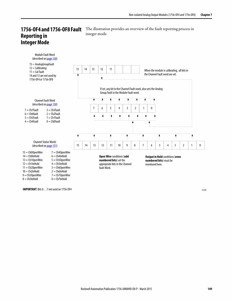
Non-isolated Analog Output Modules (1756-OF4 and 1756-OF8) Chapter 7
1756-OF4 and 1756-OF8 Fault Reporting inInteger Mode
The illustration provides an overview of the fault reporting process ininteger mode.
15 14 13 12 11
5 4 3 2 1 0
15 = AnalogGroupFault12 = Calibrating11 = Cal Fault14 and 13 are not used by 1756-OF4 or 1756-OF8
7 = Ch7Fault6 = Ch6fault5 = Ch5Fault4 = Ch4Fault
Output in Hold conditions (even numbered bits) must be monitored here.
5 49 8 7 615 14 13 12 11 10
15 = Ch0OpenWire14 = Ch0InHold13 = Ch1OpenWire12 = Ch1InHold11 = Ch2OpenWire10 = Ch2InHold9 = Ch3OpenWire8 = Ch3InHold
IMPORTANT: Bits 0…7 not used on 1756-OF4
If set, any bit in the Channel Fault word, also sets the Analog Group Fault in the Module Fault word.
When the module is calibrating, all bits in the Channel Fault word are set.
7 6
3 2 1 0
7 = Ch4OpenWire6 = Ch4InHold5 = Ch5OpenWire4 = Ch5InHold3 = Ch6OpenWire2 = Ch6InHold1 = Ch7OpenWire0 = Ch7InHold
Open Wire conditions (odd numbered bits) set the appropriate bits in the Channel fault Word.
Module Fault Word(described on page 150)
Channel Fault Word(described on page 150)
Channel Status Words(described on page 151)
3 = Ch3Fault2 = Ch2Fault1 = Ch1Fault0 = Ch0Fault
41520
Rockwell Automation Publication 1756-UM009D-EN-P - March 2015 149
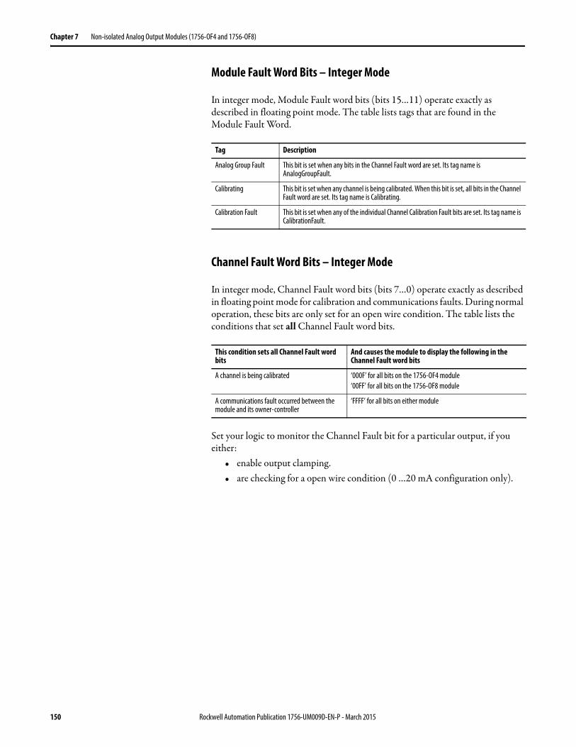
Chapter 7 Non-isolated Analog Output Modules (1756-OF4 and 1756-OF8)
Module Fault Word Bits – Integer Mode
In integer mode, Module Fault word bits (bits 15…11) operate exactly as described in floating point mode. The table lists tags that are found in the Module Fault Word.
Channel Fault Word Bits – Integer Mode
In integer mode, Channel Fault word bits (bits 7…0) operate exactly as described in floating point mode for calibration and communications faults. During normal operation, these bits are only set for an open wire condition. The table lists the conditions that set all Channel Fault word bits.
Set your logic to monitor the Channel Fault bit for a particular output, if you either:
• enable output clamping.• are checking for a open wire condition (0 …20 mA configuration only).
Tag Description
Analog Group Fault This bit is set when any bits in the Channel Fault word are set. Its tag name is AnalogGroupFault.
Calibrating This bit is set when any channel is being calibrated. When this bit is set, all bits in the Channel Fault word are set. Its tag name is Calibrating.
Calibration Fault This bit is set when any of the individual Channel Calibration Fault bits are set. Its tag name is CalibrationFault.
This condition sets all Channel Fault word bits
And causes the module to display the following in the Channel Fault word bits
A channel is being calibrated ‘000F’ for all bits on the 1756-OF4 module‘00FF’ for all bits on the 1756-OF8 module
A communications fault occurred between the module and its owner-controller
‘FFFF’ for all bits on either module
150 Rockwell Automation Publication 1756-UM009D-EN-P - March 2015
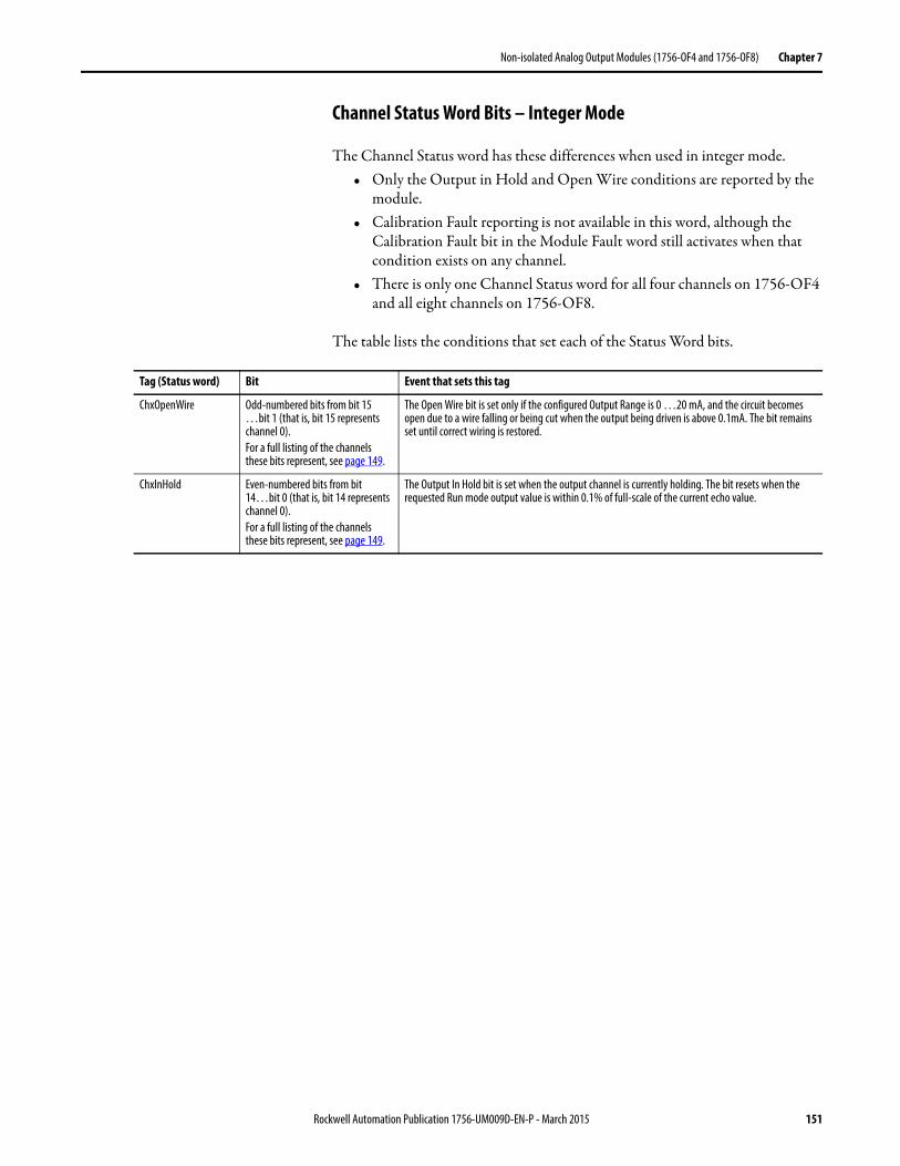
Non-isolated Analog Output Modules (1756-OF4 and 1756-OF8) Chapter 7
Channel Status Word Bits – Integer Mode
The Channel Status word has these differences when used in integer mode.• Only the Output in Hold and Open Wire conditions are reported by the
module.• Calibration Fault reporting is not available in this word, although the
Calibration Fault bit in the Module Fault word still activates when that condition exists on any channel.
• There is only one Channel Status word for all four channels on 1756-OF4 and all eight channels on 1756-OF8.
The table lists the conditions that set each of the Status Word bits.
Tag (Status word) Bit Event that sets this tag
ChxOpenWire Odd-numbered bits from bit 15 …bit 1 (that is, bit 15 represents channel 0).For a full listing of the channels these bits represent, see page 149.
The Open Wire bit is set only if the configured Output Range is 0 …20 mA, and the circuit becomes open due to a wire falling or being cut when the output being driven is above 0.1mA. The bit remains set until correct wiring is restored.
ChxInHold Even-numbered bits from bit 14…bit 0 (that is, bit 14 represents channel 0).For a full listing of the channels these bits represent, see page 149.
The Output In Hold bit is set when the output channel is currently holding. The bit resets when the requested Run mode output value is within 0.1% of full-scale of the current echo value.
Rockwell Automation Publication 1756-UM009D-EN-P - March 2015 151

Chapter 7 Non-isolated Analog Output Modules (1756-OF4 and 1756-OF8)
Notes:
152 Rockwell Automation Publication 1756-UM009D-EN-P - March 2015
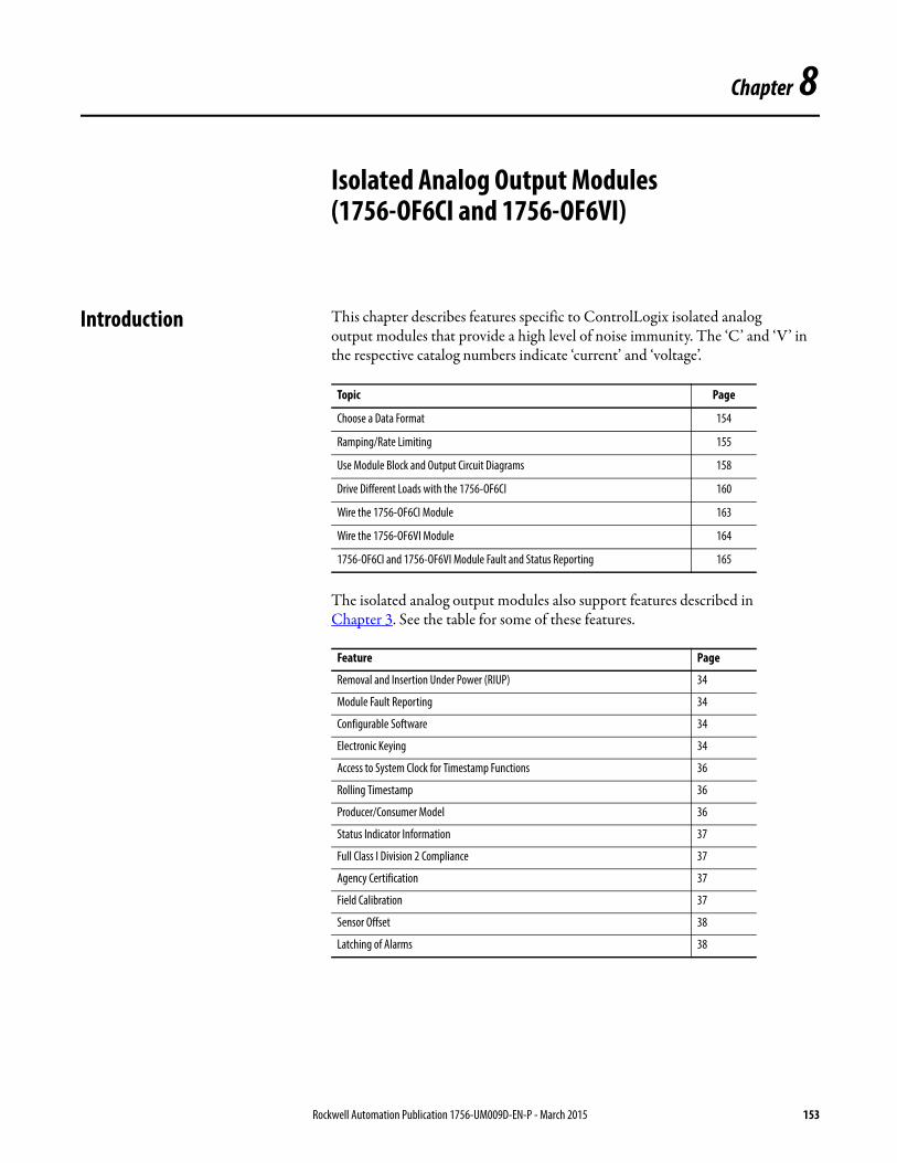
Chapter 8
Isolated Analog Output Modules(1756-OF6CI and 1756-OF6VI)
Introduction This chapter describes features specific to ControlLogix isolated analogoutput modules that provide a high level of noise immunity. The ‘C’ and ‘V’ in the respective catalog numbers indicate ‘current’ and ‘voltage’.
The isolated analog output modules also support features described inChapter 3. See the table for some of these features.
Topic Page
Choose a Data Format 154
Ramping/Rate Limiting 155
Use Module Block and Output Circuit Diagrams 158
Drive Different Loads with the 1756-OF6CI 160
Wire the 1756-OF6CI Module 163
Wire the 1756-OF6VI Module 164
1756-OF6CI and 1756-OF6VI Module Fault and Status Reporting 165
Feature Page
Removal and Insertion Under Power (RIUP) 34
Module Fault Reporting 34
Configurable Software 34
Electronic Keying 34
Access to System Clock for Timestamp Functions 36
Rolling Timestamp 36
Producer/Consumer Model 36
Status Indicator Information 37
Full Class I Division 2 Compliance 37
Agency Certification 37
Field Calibration 37
Sensor Offset 38
Latching of Alarms 38
Rockwell Automation Publication 1756-UM009D-EN-P - March 2015 153
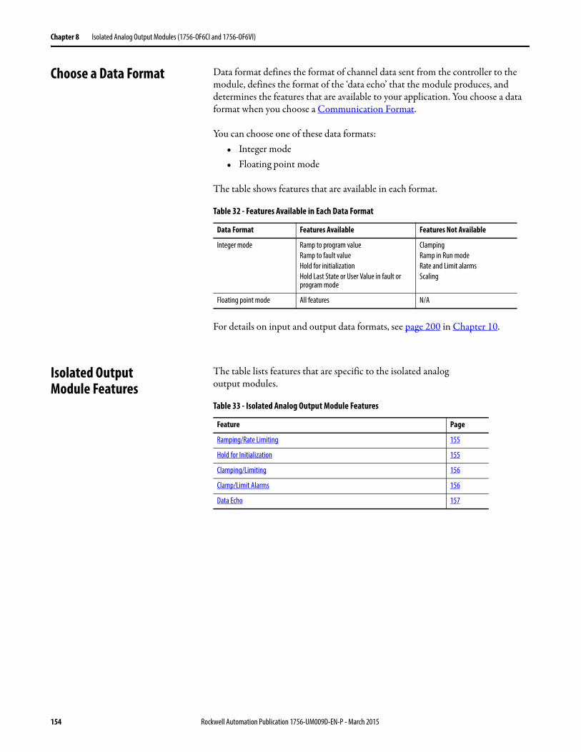
Chapter 8 Isolated Analog Output Modules (1756-OF6CI and 1756-OF6VI)
Choose a Data Format Data format defines the format of channel data sent from the controller to the module, defines the format of the ‘data echo’ that the module produces, and determines the features that are available to your application. You choose a data format when you choose a Communication Format.
You can choose one of these data formats:• Integer mode• Floating point mode
The table shows features that are available in each format.
For details on input and output data formats, see page 200 in Chapter 10.
Isolated OutputModule Features
The table lists features that are specific to the isolated analogoutput modules.
Table 32 - Features Available in Each Data Format
Data Format Features Available Features Not Available
Integer mode Ramp to program valueRamp to fault valueHold for initializationHold Last State or User Value in fault or program mode
ClampingRamp in Run modeRate and Limit alarmsScaling
Floating point mode All features N/A
Table 33 - Isolated Analog Output Module Features
Feature Page
Ramping/Rate Limiting 155
Hold for Initialization 155
Clamping/Limiting 156
Clamp/Limit Alarms 156
Data Echo 157
154 Rockwell Automation Publication 1756-UM009D-EN-P - March 2015
Isolated Analog Output Modules (1756-OF6CI and 1756-OF6VI) Chapter 8
Ramping/Rate Limiting
Ramping limits the speed at which an analog output signal can change. This prevents fast transitions in the output from damaging the devices that an output module controls. Ramping is also known as rate limiting.
The table describes the types of ramping that are possible.
The maximum rate of change in outputs is expressed in engineering units per second and called the maximum ramp rate.
See page 204 for how to enable Run mode ramping and set the maximumramp rate.
Hold for Initialization
Hold for Initialization causes outputs to hold present state until the value commanded by the controller matches the value at the output screw terminal within 0.1% of full scale, providing a bumpless transfer.
If Hold for Initialization is selected, outputs hold if there is an occurrence of any of these three conditions.
• Initial connection is established after power-up.• A new connection is established after a communications fault occurs.• There is a transition to Run mode from Program state.
The InHold bit for a channel indicates that the channel is holding.
To see how to enable the Hold for Initialization bit, see page 202.
Ramping type Description
Run mode ramping This type of ramping occurs when the module is in Run mode and begins operation at the configured maximum ramp rate when the module receives a new output level.IMPORTANT: This is only available in floating point mode.
Ramp to Program mode This type of ramping occurs when the present output value changes to the Program value after a Program command is received from the controller.
Ramp to Fault mode This type of ramping occurs when the present output value changes to the Fault value after a communications fault occurs.
Rockwell Automation Publication 1756-UM009D-EN-P - March 2015 155
Chapter 8 Isolated Analog Output Modules (1756-OF6CI and 1756-OF6VI)
Clamping/Limiting
Clamping limits the output from the analog module to remain within a range configured by the controller, even when the controller commands an output outside that range. This safety feature sets a high clamp and a low clamp.
Once clamps are determined for a module, any data received from the controller that exceeds those clamps sets an appropriate limit alarm and transitions the output to that limit but not beyond the requested value.
For example, an application sets the high clamp on a module for 8V and the low clamp for -8V. If a controller sends a value corresponding to 9V to the module, the module only applies 8V to its screw terminals.
Clamping alarms can be disabled or latched on a per channel basis.
To see how to set the clamping limits, see page 204.
Clamp/Limit AlarmsThis function works directly with clamping. When a module receives a data value from the controller that exceeds clamping limits, it applies signal values to the clamping limit but also sends a status bit to the controller notifying it that the value sent exceeds the clamping limits.
Using the example above, if a module has clamping limits of 8V and -8V but then receives data to apply 9V, only 8V is applied to the screw terminals and the module sends a status bit back to the controller informing it that the 9V value exceeds the module’s clamping limits.
To see how to enable all alarms, see page 204.
IMPORTANT Clamping is only available in floating point mode.Clamp values are in engineering scaling units and are not automatically updated when the engineering high and low scaling units are changed. Failure to update the clamp values generates a very small output signal that could be misinterpreted as a hardware problem.
IMPORTANT Limit alarms are available only in floating point mode.
156 Rockwell Automation Publication 1756-UM009D-EN-P - March 2015
Isolated Analog Output Modules (1756-OF6CI and 1756-OF6VI) Chapter 8
Data EchoData Echo automatically multicasts channel data values that match the analog value that was sent to the module’s screw terminals at that time.
Fault and status data also is sent. This data is sent in the format (floating point or integer) selected at the requested packet interval (RPI).
User Count Conversion to Output Signal
User counts can be computed in Integer mode for the 1756-OF6CI and 1756-OF6VI modules.
The straight line formulas that can be used to calculate or program aCompute (CPT) instruction are shown in the table.
For example, if you have 3.5 mA in the 0…20 mV range, theuser counts = -21884. Counts = 6231 for 2 V in the +/-10V range.
For a table with related values, refer to ControlLogix 1756-OF6CI and OF6VI User Count Conversion to Output Signal, Knowledgebase Technical NoteIDs 41574 and 41576.
Available Range User Count Formula
O…20 mA y = 3109.7560975609754x-32768where y = counts; x = mA
+/-10V y = 3115.669867833032x-0.5where y = counts; x = V
Rockwell Automation Publication 1756-UM009D-EN-P - March 2015 157
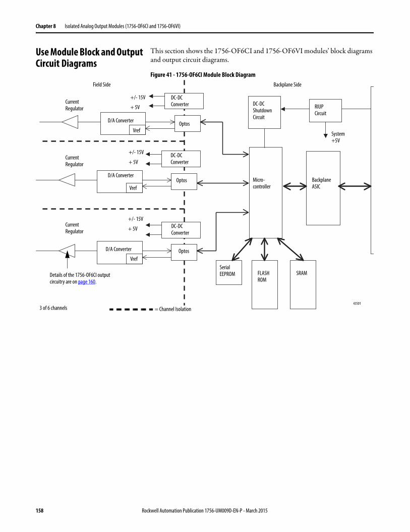
Chapter 8 Isolated Analog Output Modules (1756-OF6CI and 1756-OF6VI)
Use Module Block and Output Circuit Diagrams
This section shows the 1756-OF6CI and 1756-OF6VI modules’ block diagrams and output circuit diagrams.
Figure 41 - 1756-OF6CI Module Block Diagram
DC-DC Converter
D/A Converter
RIUP Circuit
43501
VrefOptos
Micro-controller
Backplane ASIC
Serial EEPROM FLASH
ROMSRAM
System +5V
Field Side Backplane Side
DC-DC Shutdown Circuit
+/- 15V
+ 5V
Details of the 1756-OF6CI output circuitry are on page 160.
Current Regulator
Current Regulator
Current Regulator
DC-DC Converter
D/A Converter
VrefOptos
+/- 15V
+ 5V
DC-DC Converter
D/A Converter
VrefOptos
+/- 15V
+ 5V
3 of 6 channels = Channel Isolation
158 Rockwell Automation Publication 1756-UM009D-EN-P - March 2015
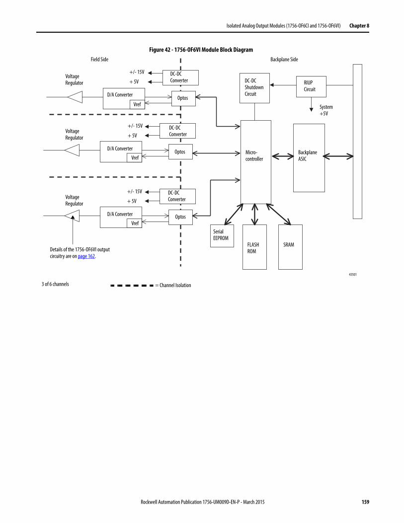
Isolated Analog Output Modules (1756-OF6CI and 1756-OF6VI) Chapter 8
Figure 42 - 1756-OF6VI Module Block Diagram
DC-DC Converter
D/A Converter
RIUP Circuit
43501
VrefOptos
Serial EEPROM
FLASH ROM
SRAM
System +5V
Field Side Backplane Side
DC-DC Shutdown Circuit
+/- 15V
+ 5V
Details of the 1756-OF6VI output circuitry are on page 162.
Voltage Regulator
Voltage Regulator
Voltage Regulator
DC-DC Converter
D/A Converter
VrefOptos
+/- 15V
+ 5V
DC-DC Converter
D/A Converter
VrefOptos
+/- 15V
+ 5V
Micro-controller
Backplane ASIC
3 of 6 channels = Channel Isolation
Rockwell Automation Publication 1756-UM009D-EN-P - March 2015 159
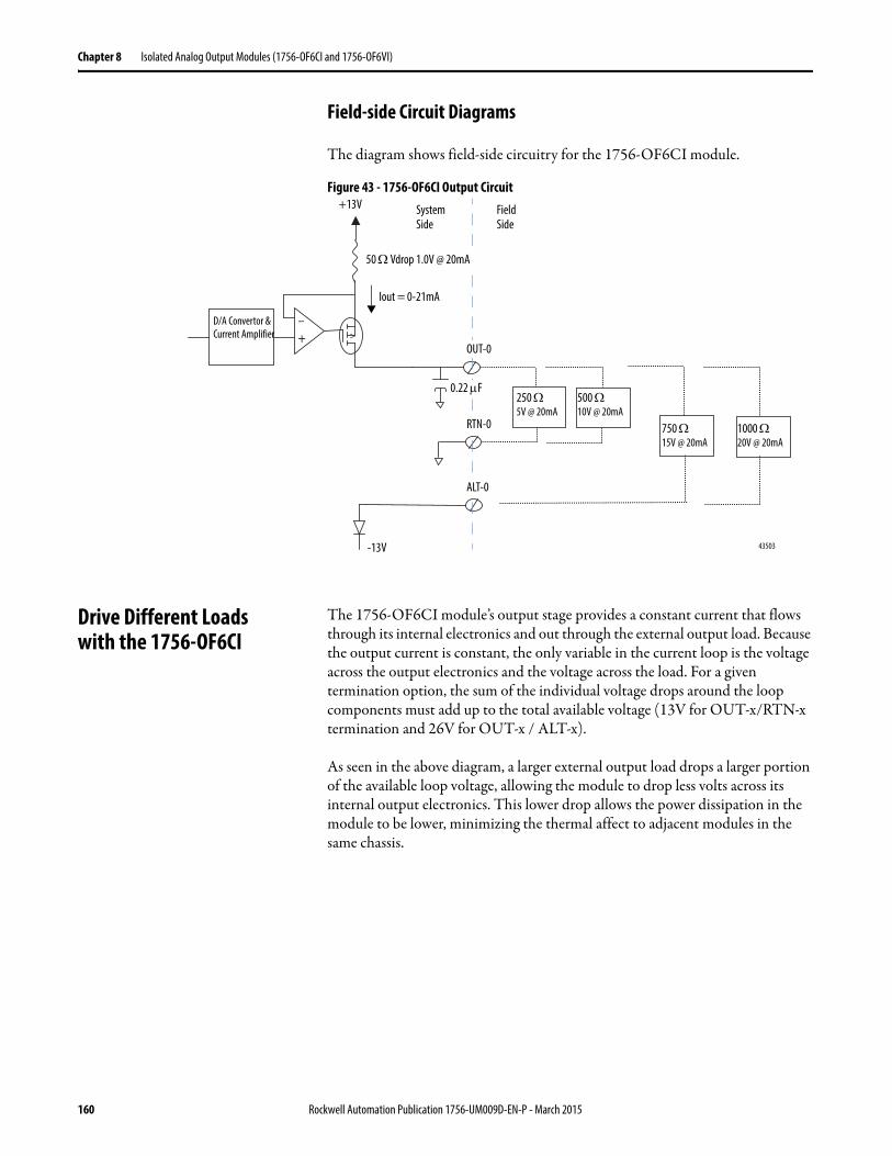
Chapter 8 Isolated Analog Output Modules (1756-OF6CI and 1756-OF6VI)
Field-side Circuit Diagrams
The diagram shows field-side circuitry for the 1756-OF6CI module.
Figure 43 - 1756-OF6CI Output Circuit
Drive Different Loadswith the 1756-OF6CI
The 1756-OF6CI module’s output stage provides a constant current that flows through its internal electronics and out through the external output load. Because the output current is constant, the only variable in the current loop is the voltage across the output electronics and the voltage across the load. For a given termination option, the sum of the individual voltage drops around the loop components must add up to the total available voltage (13V for OUT-x/RTN-x termination and 26V for OUT-x / ALT-x).
As seen in the above diagram, a larger external output load drops a larger portion of the available loop voltage, allowing the module to drop less volts across its internal output electronics. This lower drop allows the power dissipation in the module to be lower, minimizing the thermal affect to adjacent modules in the same chassis.
43503
–
250 5V @ 20mA
+13V
+
Iout = 0-21mA
D/A Convertor & Current Amplifier
-13V
500 10V @ 20mA
750 15V @ 20mA
1000 20V @ 20mA
Field Side
System Side
50 Vdrop 1.0V @ 20mA
OUT-0
0.22 F
RTN-0
ALT-0
160 Rockwell Automation Publication 1756-UM009D-EN-P - March 2015
Isolated Analog Output Modules (1756-OF6CI and 1756-OF6VI) Chapter 8
For loads under 550 , the module’s +13V internal voltage source can supply voltage for currents up to 21 mA. For loads over 550 , additional compliance voltage is required. In this case, you must use the ALT terminal to provide the additional -13V source.
For any size load (that is, 0…1000 ), the output channels function if terminated between OUT-x and ALT-x. To improve module reliability and product life, we recommend you:
• Terminate the output channels between the OUT-x and RTN-x terminals for loads of 0…550
• Terminate the output channels between the OUT-x and ALT-x terminals for loads of 551…1000 .
IMPORTANT If you are unsure of the load, you can terminate the output channels between OUT-x and ALT-x and the module operates but reliability can be compromised at elevated temperatures.For example, if you terminate the output channels between OUT-x and ALT-x and use a 250 load, the module operates but the lower load results in higher operating temperatures and can affect the module’s reliability over time.We recommend you terminate the output channels as described above whenever possible.
Rockwell Automation Publication 1756-UM009D-EN-P - March 2015 161

Chapter 8 Isolated Analog Output Modules (1756-OF6CI and 1756-OF6VI)
Figure 44 - 1756-OF6VI Output Circuit
The diagram shows field-side circuitry for the 1756-OF6CI module.
43508
RET-x
+ 15V3160
0.047 F
IN-x/VD/A converter
8250
- 15V
0.00047 F
Voltage Output
162 Rockwell Automation Publication 1756-UM009D-EN-P - March 2015
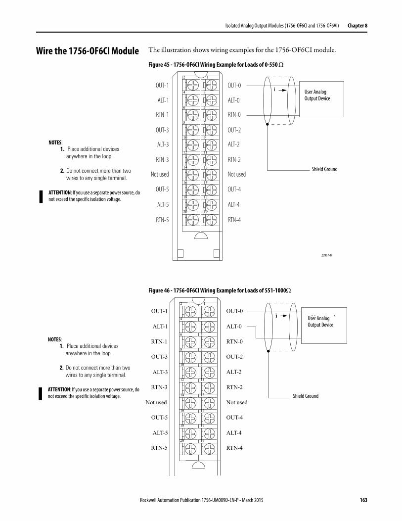
Isolated Analog Output Modules (1756-OF6CI and 1756-OF6VI) Chapter 8
Wire the 1756-OF6CI Module The illustration shows wiring examples for the 1756-OF6CI module.
Figure 45 - 1756-OF6CI Wiring Example for Loads of 0-550
Figure 46 - 1756-OF6CI Wiring Example for Loads of 551-1000
OUT-0
ALT-0
RTN-0
OUT-2
ALT-2
RTN-2
Not used
OUT-4
ALT-4
RTN-4
OUT-1
ALT-1
RTN-1
OUT-3
ALT-3
RTN-3
Not used
OUT-5
ALT-5
RTN-5
Shield Ground
User Analog
Output Device
12
34
56
78
910
1112
1314
1516
1718
1920
i
NOTES:1. Place additional devices
anywhere in the loop.
2. Do not connect more than two wires to any single terminal.
ATTENTION: If you use a separate power source, do not exceed the specific isolation voltage.
User AnalogOutput Device
i
Shield Ground
20967-M
Shield Ground
User Analog
Output Device
OUT-0
ALT-0
RTN-0
OUT-2
ALT-2
RTN-2
Not used
OUT-4
ALT-4
RTN-4
OUT-1
ALT-1
RTN-1
OUT-3
ALT-3
RTN-3
Not used
OUT-5
ALT-5
RTN-5
12
34
56
78
910
1112
1314
1516
1718
1920
i
NOTES:1. Place additional devices
anywhere in the loop.
2. Do not connect more than two wires to any single terminal.
ATTENTION: If you use a separate power source, do not exceed the specific isolation voltage.
User AnalogOutput Device
i
Shield Ground
Rockwell Automation Publication 1756-UM009D-EN-P - March 2015 163
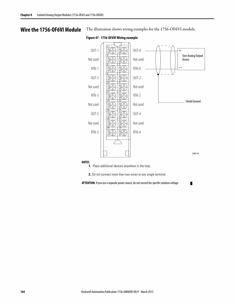
Chapter 8 Isolated Analog Output Modules (1756-OF6CI and 1756-OF6VI)
Wire the 1756-OF6VI Module The illustration shows wiring examples for the 1756-OF6VI module.
Figure 47 - 1756-OF6VI Wiring example
OUT-0
Not used
RTN-0
OUT-2
Not used
RTN-2
Not used
OUT-4
Not used
RTN-4
OUT-1
Not used
RTN-1
OUT-3
Not used
RTN-3
Not used
OUT-5
Not used
RTN-5
Shield Ground
User Analog
Output Device
12
34
56
78
910
1112
1314
1516
1718
1920
+
–
NOTES:1. Place additional devices anywhere in the loop.
2. Do not connect more than two wires to any single terminal.
ATTENTION: If you use a separate power source, do not exceed the specific isolation voltage.
+
—
User Analog Output Device
Shield Ground
20967-M
164 Rockwell Automation Publication 1756-UM009D-EN-P - March 2015
Isolated Analog Output Modules (1756-OF6CI and 1756-OF6VI) Chapter 8
1756-OF6CI and 1756-OF6VI Module Fault and Status Reporting
The 1756-OF6CI and 1756-OF6VI modules multicast status and fault data to the owner-listening controller with their channel data. The fault data is arranged in such a manner as to let you choose the level of granularity for examining fault conditions.
Three levels of tags work together to provide increasing degree of detail as to the specific cause of faults on the module.
The table lists tags that can be examined in ladder logic to indicate when a fault occurs.
Tag Description
Module Fault Word This word provides fault summary reporting. Its tag name is ModuleFaults.
Channel Fault Word This word provides underrange, overrange and communications fault reporting. Its tag name is ChannelFaults.
Channel Status Words This word provides individual channel underrange and overrange fault reporting for process alarms, rate alarms and calibration faults. Its tag name is ChxStatus.
IMPORTANT Differences exist between floating point and integer modes as they relate to module fault reporting. These differences are explained in the following two sections.
Rockwell Automation Publication 1756-UM009D-EN-P - March 2015 165
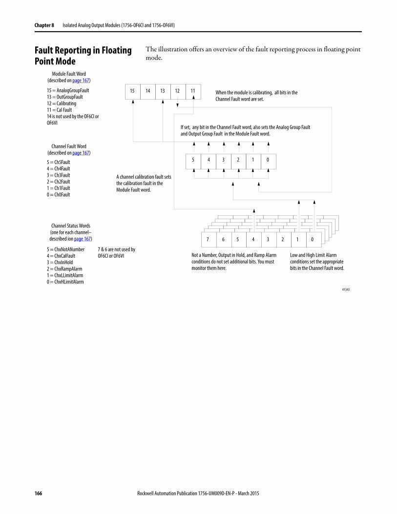
Chapter 8 Isolated Analog Output Modules (1756-OF6CI and 1756-OF6VI)
Fault Reporting in Floating Point Mode
The illustration offers an overview of the fault reporting process in floating point mode.
15 14 13 12 11
5 4 3 2 1 0
5 4 3 2 1 07 6
15 = AnalogGroupFault13 = OutGroupFault12 = Calibrating11 = Cal Fault14 is not used by the OF6CI or OF6VI
5 = Ch5Fault4 = Ch4Fault3 = Ch3Fault2 = Ch2Fault1 = Ch1Fault0 = Ch0Fault
5 = ChxNotANumber4 = ChxCalFault3 = ChxInHold2 = ChxRampAlarm1 = ChxLLimitAlarm0 = ChxHLimitAlarm
Not a Number, Output in Hold, and Ramp Alarm conditions do not set additional bits. You must monitor them here.
Low and High Limit Alarm conditions set the appropriate bits in the Channel Fault word.
7 & 6 are not used by OF6CI or OF6VI
If set, any bit in the Channel Fault word, also sets the Analog Group Fault and Output Group Fault in the Module Fault word.
A channel calibration fault sets the calibration fault in the Module Fault word.
When the module is calibrating, all bits in the Channel Fault word are set.
Module Fault Word(described on page 167)
Channel Fault Word(described on page 167)
Channel Status Words(one for each channel–described ion page 167)
41343
166 Rockwell Automation Publication 1756-UM009D-EN-P - March 2015
Isolated Analog Output Modules (1756-OF6CI and 1756-OF6VI) Chapter 8
Module Fault Word Bits – Floating Point Mode
Bits in this word provide the highest level of fault detection. A nonzero condition in this word reveals that a fault exists on the module. You can examine further down to isolate the fault.
The table lists tags that are found in the Module Fault Word:
Channel Fault Word Bits – Floating Point Mode
During normal module operation, Channel Fault word bits are set if any of the respective channels has a High or Low Limit Alarm. Checking this word for a nonzero condition is a quick way to check for High or Low Limit Alarm condition on a channel.
The table lists the conditions that set all Channel Fault word bits:
Set your logic to monitor the Channel Fault bit for a particular output, if you either:
• set the high and low limit alarms outside your operating range.• disable output limiting.
Channel Status Word Bits – Floating Point Mode
Any of the six Channel Status words, one for each channel, displays a nonzero condition if that particular channel has faulted for the conditions listed below. Some of these bits set bits in other Fault words.
When the High or Low Limit Alarm bits (bits 1 and 0) in any of the words are set, the appropriate bit is set in the Channel Fault word.
Tag Description
Analog Group Fault This bit is set when any bits in the Channel Fault word are set. Its tag name is AnalogGroupFault.
Output Group Fault This bit is set when any bits in the Channel Fault word are set. Its tag name is OutputGroupFault.
Calibrating This bit is set when any channel is being calibrated. When this bit is set, all bits in the Channel Fault word are set. Its tag nameis Calibrating.
Calibration Fault This bit is set when any of the individual Channel Calibration Fault bits are set. Its tag name is CalibrationFault.
This condition sets all Channel Fault word bits
And causes the module to display the following in the Channel Fault word bits
A channel is being calibrated ’003F’ for all bits
A communications fault occurred between the module and its owner-controller
’FFFF’ for all bits
Rockwell Automation Publication 1756-UM009D-EN-P - March 2015 167
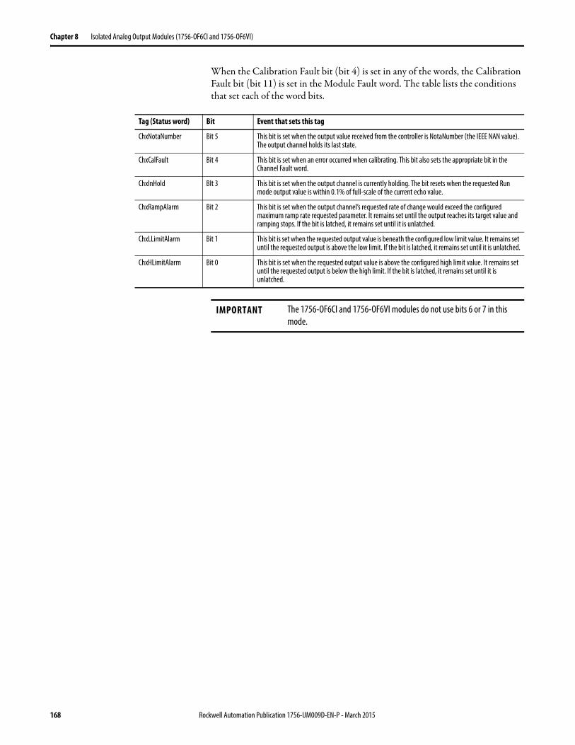
Chapter 8 Isolated Analog Output Modules (1756-OF6CI and 1756-OF6VI)
When the Calibration Fault bit (bit 4) is set in any of the words, the Calibration Fault bit (bit 11) is set in the Module Fault word. The table lists the conditions that set each of the word bits.
Tag (Status word) Bit Event that sets this tag
ChxNotaNumber Bit 5 This bit is set when the output value received from the controller is NotaNumber (the IEEE NAN value). The output channel holds its last state.
ChxCalFault Bit 4 This bit is set when an error occurred when calibrating. This bit also sets the appropriate bit in the Channel Fault word.
ChxInHold BIt 3 This bit is set when the output channel is currently holding. The bit resets when the requested Run mode output value is within 0.1% of full-scale of the current echo value.
ChxRampAlarm Bit 2 This bit is set when the output channel’s requested rate of change would exceed the configured maximum ramp rate requested parameter. It remains set until the output reaches its target value and ramping stops. If the bit is latched, it remains set until it is unlatched.
ChxLLimitAlarm Bit 1 This bit is set when the requested output value is beneath the configured low limit value. It remains set until the requested output is above the low limit. If the bit is latched, it remains set until it is unlatched.
ChxHLimitAlarm Bit 0 This bit is set when the requested output value is above the configured high limit value. It remains set until the requested output is below the high limit. If the bit is latched, it remains set until it is unlatched.
IMPORTANT The 1756-OF6CI and 1756-OF6VI modules do not use bits 6 or 7 in this mode.
168 Rockwell Automation Publication 1756-UM009D-EN-P - March 2015
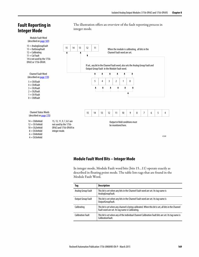
Isolated Analog Output Modules (1756-OF6CI and 1756-OF6VI) Chapter 8
Fault Reporting in Integer Mode
The illustration offers an overview of the fault reporting process ininteger mode.
Module Fault Word Bits – Integer Mode
In integer mode, Module Fault word bits (bits 15…11) operate exactly as described in floating point mode. The table lists tags that are found in the Module Fault Word.
15 14 13 12 11
5 4 3 2 1 0
15 = AnalogGroupFault13 = OutGroupFault12 = Calibrating11 = Cal Fault14 is not used by the 1756-OF6CI or 1756-OF6VI.
5 = Ch5Fault4 = Ch4Fault3 = Ch3Fault2 = Ch2Fault1 = Ch1Fault0 = Ch0Fault
Output in Hold conditions must be monitored here.
5 49 8 7 615 14 13 12 11 10
14 = Ch0InHold12 = Ch1InHold10 = Ch2InHold 8 = Ch3InHold 6 = Ch4InHold 4 = Ch5InHold
15, 13, 11, 9, 7, & 5 are not used by the 1756-OF6CI and 1756-OF6VI in integer mode.
If set, any bit in the Channel Fault word, also sets the Analog Group Fault and Output Group Fault in the Module Fault word.
When the module is calibrating, all bits in the Channel Fault word are set.
Module Fault Word(described on page 169)
Channel Fault Word(described on page 170)
Channel Status Words(described on page 170)
41349
Tag Description
Analog Group Fault This bit is set when any bits in the Channel Fault word are set. Its tag name is AnalogGroupFault.
Output Group Fault This bit is set when any bits in the Channel Fault word are set. Its tag name is OutputGroupFault.
Calibrating This bit is set when any channel is being calibrated. When this bit is set, all bits in the Channel Fault word are set. Its tag name is Calibrating.
Calibration Fault This bit is set when any of the individual Channel Calibration Fault bits are set. Its tag name is CalibrationFault.
Rockwell Automation Publication 1756-UM009D-EN-P - March 2015 169

Chapter 8 Isolated Analog Output Modules (1756-OF6CI and 1756-OF6VI)
Channel Fault Word Bits – Integer Mode
In integer mode, Channel Fault word bits (bits 5…0) operate exactly as described in floating point mode for calibration and communications faults. The table lists the conditions that set all Channel Fault word bits.
Set your logic to monitor the Channel Fault bit for a particular output, if you either:
• set the high and low limit alarms outside your operating range• disable output limiting.
Channel Status Word Bits in Integer Mode
The Channel Status word has the following differences when used in integer mode.
• Only the Output in Hold condition is reported by the module.• Calibration Fault reporting is not available in this word, although the
Calibration Fault bit in the Module Fault word still activates when that condition exists on any channel.
• There is only one Channel Status word for all six channels.
The table lists the conditions that set each of the word bits.
This condition sets all Channel Fault word bits
And causes the module to display the following in the Channel Fault word bits
A channel is being calibrated ’003F’ for all bits
A communications fault occurred between the module and its owner-controller
’FFFF’ for all bits
Tag (Status word) Bit Event that sets this tag
ChxInHold Even-numbered bits from bit 14…bit 0 (that is, bit 14 represents channel 0).For a full listing of the channels these bits represent, see page 169.
The Output In Hold bit is set when the output channel is currently holding. The bit resets when the requested Run mode output value is within 0.1% of full-scale of the current echo value.
IMPORTANT The 1756-OF6CI and 1756-OF6VI modules do not use bits 15, 13, 11, 9, 7 or 5 in this mode.
170 Rockwell Automation Publication 1756-UM009D-EN-P - March 2015
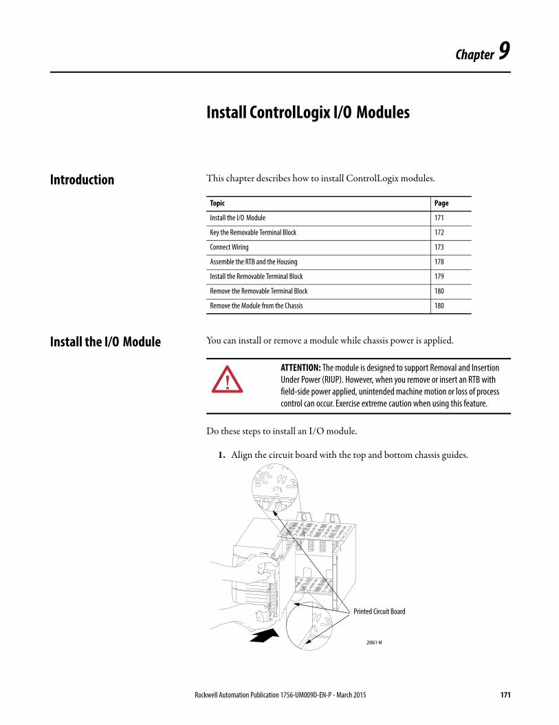
Chapter 9
Install ControlLogix I/O Modules
Introduction This chapter describes how to install ControlLogix modules.
Install the I/O Module You can install or remove a module while chassis power is applied.
Do these steps to install an I/O module.
1. Align the circuit board with the top and bottom chassis guides.
Topic Page
Install the I/O Module 171
Key the Removable Terminal Block 172
Connect Wiring 173
Assemble the RTB and the Housing 178
Install the Removable Terminal Block 179
Remove the Removable Terminal Block 180
Remove the Module from the Chassis 180
ATTENTION: The module is designed to support Removal and Insertion Under Power (RIUP). However, when you remove or insert an RTB with field-side power applied, unintended machine motion or loss of process control can occur. Exercise extreme caution when using this feature.
Printed Circuit Board
20861-M
Rockwell Automation Publication 1756-UM009D-EN-P - March 2015 171

Chapter 9 Install ControlLogix I/O Modules
2. Slide the module into the chassis until the module locking tab clicks.
Key the Removable Terminal Block
Key the RTB to prevent inadvertently connecting the incorrect RTB toyour module. When the RTB mounts onto the module, keying positions matches up.
For example, if you place a U-shaped keying band in slot 4 on the module, you cannot place a wedge-shaped tab in slow 4 on the RTB or your RTB does not mount on the module. We recommend that you use a unique keying pattern for each slot in the chassis.
1. Insert the U-shaped band with the long side near the terminals.
2. Push the band onto the module until it snaps into place.
3. Key the RTB in positions that correspond to unkeyed module positions. Insert the wedge-shaped tab on the RTB with the rounded edge first. Push the tab onto the RTB until it stops.
Locking tab
20862-M
U-shaped keying band
20850-M
172 Rockwell Automation Publication 1756-UM009D-EN-P - March 2015
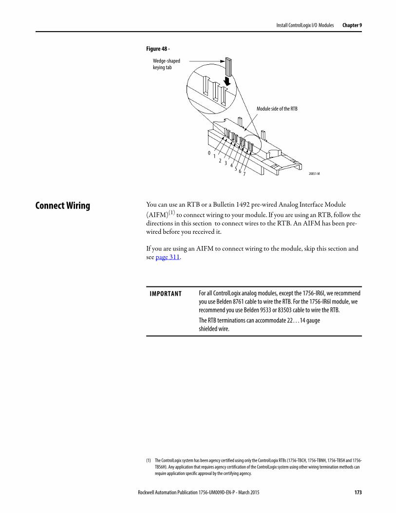
Install ControlLogix I/O Modules Chapter 9
Figure 48 -
Connect Wiring You can use an RTB or a Bulletin 1492 pre-wired Analog Interface Module (AIFM)(1) to connect wiring to your module. If you are using an RTB, follow the directions in this section to connect wires to the RTB. An AIFM has been pre-wired before you received it.
If you are using an AIFM to connect wiring to the module, skip this section and see page 311.
Wedge-shaped keying tab
Module side of the RTB
0 12 3 4 5 6 7 20851-M
(1) The ControlLogix system has been agency certified using only the ControlLogix RTBs (1756-TBCH, 1756-TBNH, 1756-TBSH and 1756-TBS6H). Any application that requires agency certification of the ControlLogix system using other wiring termination methods can require application specific approval by the certifying agency.
IMPORTANT For all ControlLogix analog modules, except the 1756-IR6I, we recommend you use Belden 8761 cable to wire the RTB. For the 1756-IR6I module, we recommend you use Belden 9533 or 83503 cable to wire the RTB.The RTB terminations can accommodate 22…14 gaugeshielded wire.
Rockwell Automation Publication 1756-UM009D-EN-P - March 2015 173
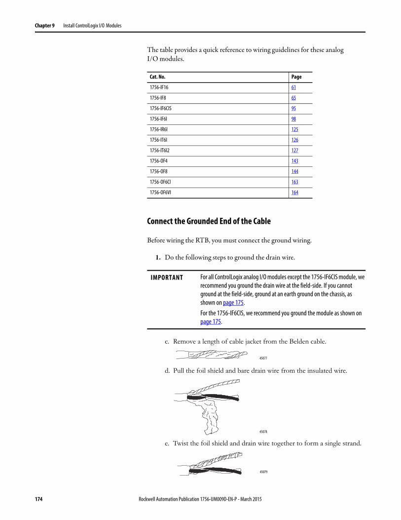
Chapter 9 Install ControlLogix I/O Modules
The table provides a quick reference to wiring guidelines for these analogI/O modules.
Connect the Grounded End of the Cable
Before wiring the RTB, you must connect the ground wiring.
1. Do the following steps to ground the drain wire.
c. Remove a length of cable jacket from the Belden cable.
d. Pull the foil shield and bare drain wire from the insulated wire.
e. Twist the foil shield and drain wire together to form a single strand.
Cat. No. Page
1756-IF16 61
1756-IF8 65
1756-IF6CIS 95
1756-IF6I 98
1756-IR6I 125
1756-IT6I 126
1756-IT6I2 127
1756-OF4 143
1756-OF8 144
1756-OF6CI 163
1756-OF6VI 164
IMPORTANT For all ControlLogix analog I/O modules except the 1756-IF6CIS module, we recommend you ground the drain wire at the field-side. If you cannot ground at the field-side, ground at an earth ground on the chassis, as shown on page 175.For the 1756-IF6CIS, we recommend you ground the module as shown on page 175.
45077
45078
45079
174 Rockwell Automation Publication 1756-UM009D-EN-P - March 2015
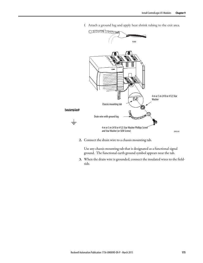
Install ControlLogix I/O Modules Chapter 9
f. Attach a ground lug and apply heat shrink tubing to the exit area.
2. Connect the drain wire to a chassis mounting tab.
Use any chassis mounting tab that is designated as a functional signal ground. The functional earth ground symbol appears near the tab.
3. When the drain wire is grounded, connect the insulated wires to the field-side.
45080
Chassis mounting tab
Drain wire with ground lug
4 m or 5 m (#10 or #12) Star Washer
4 m or 5 m (#10 or #12) Star Washer Phillips Screw and Star Washer (or SEM Screw) 20918-M
Functional Earth Ground Symbol
Rockwell Automation Publication 1756-UM009D-EN-P - March 2015 175
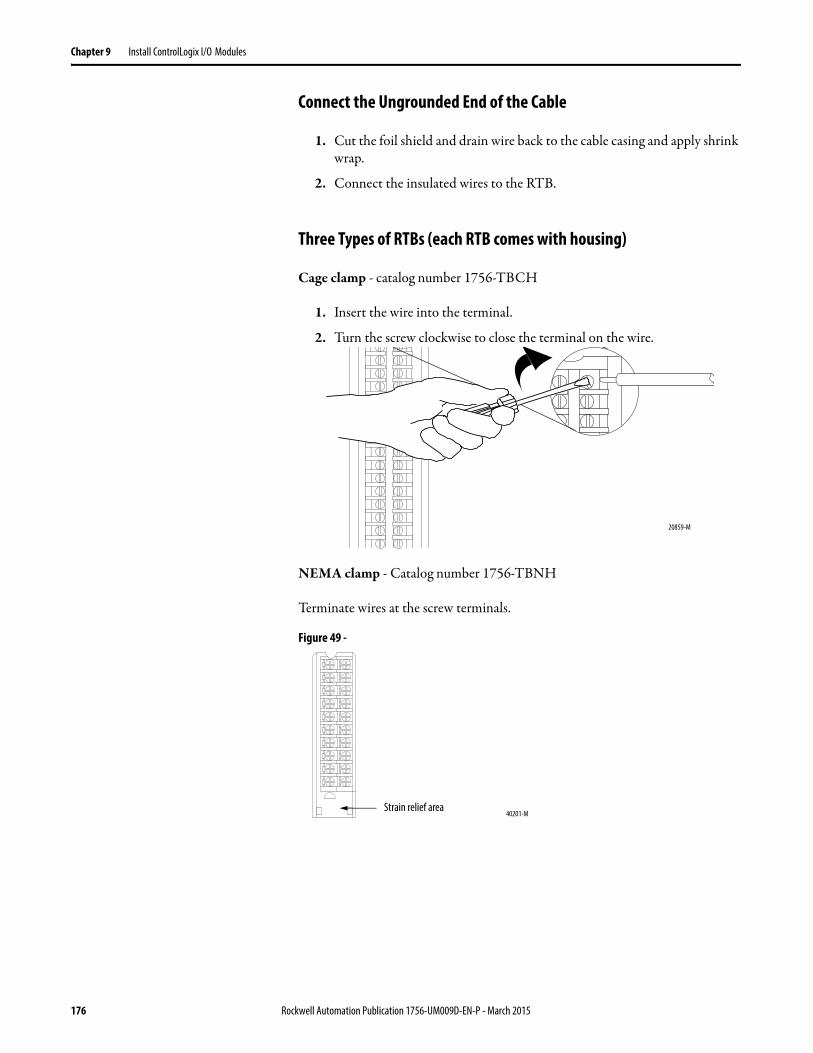
Chapter 9 Install ControlLogix I/O Modules
Connect the Ungrounded End of the Cable
1. Cut the foil shield and drain wire back to the cable casing and apply shrink wrap.
2. Connect the insulated wires to the RTB.
Three Types of RTBs (each RTB comes with housing)
Cage clamp - catalog number 1756-TBCH
1. Insert the wire into the terminal.
2. Turn the screw clockwise to close the terminal on the wire.
NEMA clamp - Catalog number 1756-TBNH
Terminate wires at the screw terminals.
Figure 49 -
20859-M
40201-MStrain relief area
176 Rockwell Automation Publication 1756-UM009D-EN-P - March 2015
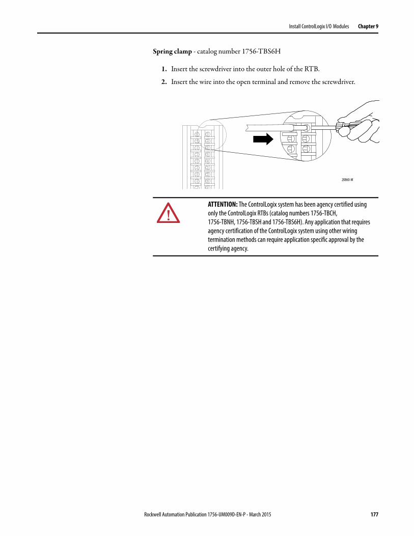
Install ControlLogix I/O Modules Chapter 9
Spring clamp - catalog number 1756-TBS6H
1. Insert the screwdriver into the outer hole of the RTB.
2. Insert the wire into the open terminal and remove the screwdriver.
ATTENTION: The ControlLogix system has been agency certified using only the ControlLogix RTBs (catalog numbers 1756-TBCH,1756-TBNH, 1756-TBSH and 1756-TBS6H). Any application that requires agency certification of the ControlLogix system using other wiring termination methods can require application specific approval by the certifying agency.
20860-M
Rockwell Automation Publication 1756-UM009D-EN-P - March 2015 177
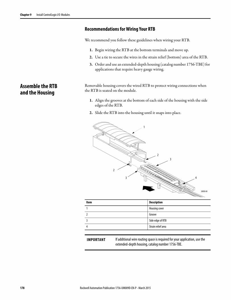
Chapter 9 Install ControlLogix I/O Modules
Recommendations for Wiring Your RTB
We recommend you follow these guidelines when wiring your RTB.
1. Begin wiring the RTB at the bottom terminals and move up.
2. Use a tie to secure the wires in the strain relief (bottom) area of the RTB.
3. Order and use an extended-depth housing (catalog number 1756-TBE) for applications that require heavy gauge wiring.
Assemble the RTBand the Housing
Removable housing covers the wired RTB to protect wiring connections when the RTB is seated on the module.
1. Align the grooves at the bottom of each side of the housing with the side edges of the RTB.
2. Slide the RTB into the housing until it snaps into place.
1
4
32
3
2
20858-M
Item Description
1 Housing cover
2 Groove
3 Side edge of RTB
4 Strain relief area
IMPORTANT If additional wire routing space is required for your application, use the extended-depth housing, catalog number 1756-TBE.
178 Rockwell Automation Publication 1756-UM009D-EN-P - March 2015
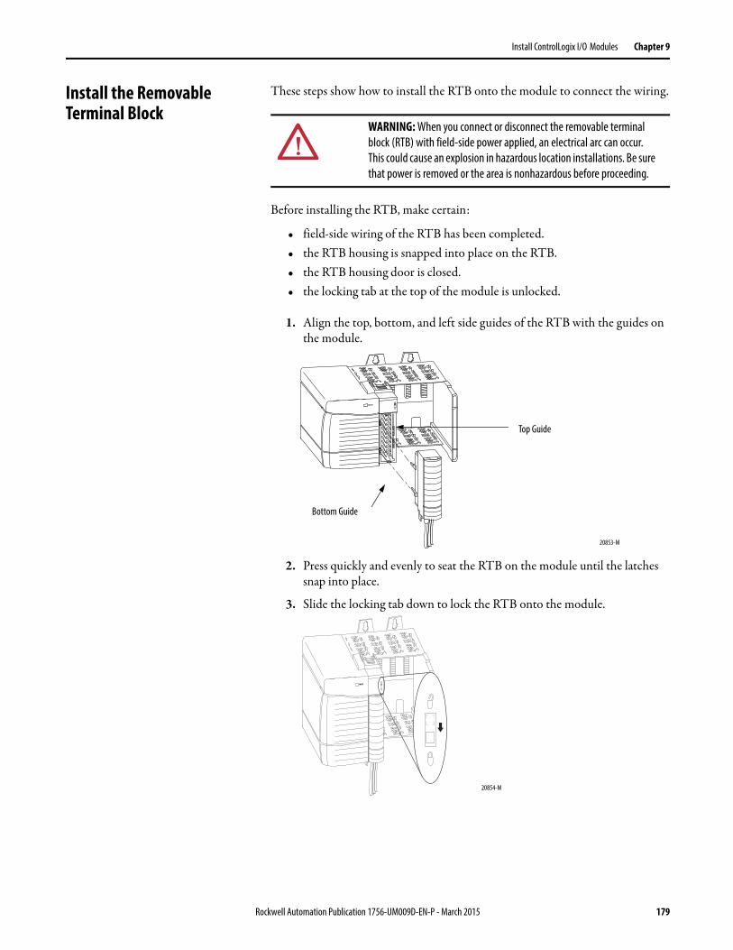
Install ControlLogix I/O Modules Chapter 9
Install the Removable Terminal Block
These steps show how to install the RTB onto the module to connect the wiring.
Before installing the RTB, make certain:
• field-side wiring of the RTB has been completed.• the RTB housing is snapped into place on the RTB.• the RTB housing door is closed.• the locking tab at the top of the module is unlocked.
1. Align the top, bottom, and left side guides of the RTB with the guides on the module.
2. Press quickly and evenly to seat the RTB on the module until the latches snap into place.
3. Slide the locking tab down to lock the RTB onto the module.
WARNING: When you connect or disconnect the removable terminal block (RTB) with field-side power applied, an electrical arc can occur. This could cause an explosion in hazardous location installations. Be sure that power is removed or the area is nonhazardous before proceeding.
Top Guide
Bottom Guide
20853-M
20854-M
Rockwell Automation Publication 1756-UM009D-EN-P - March 2015 179
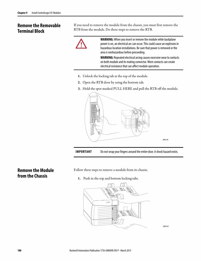
Chapter 9 Install ControlLogix I/O Modules
Remove the Removable Terminal Block
If you need to remove the module from the chassis, you must first remove the RTB from the module. Do these steps to remove the RTB.
1. Unlock the locking tab at the top of the module.
2. Open the RTB door by using the bottom tab.
3. Hold the spot marked PULL HERE and pull the RTB off the module.
Remove the Modulefrom the Chassis
Follow these steps to remove a module from its chassis.
1. Push in the top and bottom locking tabs.
WARNING: When you insert or remove the module while backplane power is on, an electrical arc can occur. This could cause an explosion in hazardous location installations. Be sure that power is removed or the area is nonhazardous before proceeding.WARNING: Repeated electrical arcing causes excessive wear to contacts on both module and its mating connector. Worn contacts can create electrical resistance that can affect module operation.
IMPORTANT Do not wrap your fingers around the entire door. A shock hazard exists.
20855-M
20856-M
180 Rockwell Automation Publication 1756-UM009D-EN-P - March 2015
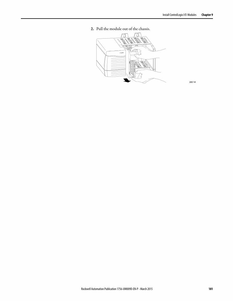
Install ControlLogix I/O Modules Chapter 9
2. Pull the module out of the chassis.
20857-M
Rockwell Automation Publication 1756-UM009D-EN-P - March 2015 181

Chapter 9 Install ControlLogix I/O Modules
Notes:
182 Rockwell Automation Publication 1756-UM009D-EN-P - March 2015
Chapter 10
Configure ControlLogix Analog I/O Modules
Introduction You must configure your module upon installation. The module does not work until it has been configured.
In most cases, you can use RSLogix 5000 programming software to configure your analog I/O module. The programming software uses default configurations, such as RTS, RPI, and so forth, to get your I/O module to communicate with the owner-controller.
However, there are situations in which it can make sense to modify the default settings. You can maintain custom settings on tabs from the Module Properties dialog box. This section provides step-by-step instructions for creating default and custom configurations
Topic Page
Full Configuration Profile Diagram 185
Create a New Module 186
Modify Default Configuration for Input Modules 191
Configure the RTD Module 198
Configure the Thermocouple Modules 199
Modify Default Configuration for Output Modules 200
Download Configuration Data to the Module 205
Edit Configuration 206
Reconfigure Module Parameters in Run Mode 207
Reconfigure Parameters in Program Mode 209
Configure I/O Modules in a Remote Chassis 210
View Module Tags 211
Rockwell Automation Publication 1756-UM009D-EN-P - March 2015 183
Chapter 10 Configure ControlLogix Analog I/O Modules
Configuration Process Overview
Follow these basic steps to configure a ControlLogix analog I/O module by using the RSLogix 5000 software.
1. Create a new module.
2. Accept the default configuration or change it to specific configuration (customized) for the module.
3. Edit a configuration for a module when changes are needed.
Each of these steps is explained in detail in the following pages. A chart that shows the full configuration profile is on page 185.
IMPORTANT This section focuses on configuring I/O modules in a local chassis. To configure I/O modules in a remote chassis, you must follow all the detailed procedures with two additional steps. See page 210 for details.RSLogix 5000 programming software must be installed on your computer to complete the procedures for both default and custom configurations.For software installation instructions and to learn how to navigate the software package, see the RSLogix 5000 Getting Results Guide.
184 Rockwell Automation Publication 1756-UM009D-EN-P - March 2015
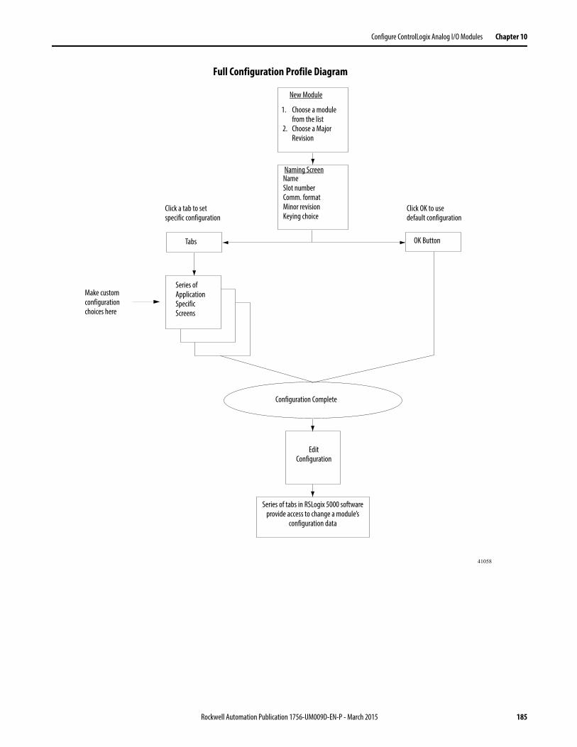
Configure ControlLogix Analog I/O Modules Chapter 10
Full Configuration Profile Diagram
1. Choose a modulefrom the list
2. Choose a MajorRevision
NameSlot numberComm. formatMinor revisionKeying choice
Series of Application Specific Screens
Make custom configuration choices here
Series of tabs in RSLogix 5000 software provide access to change a module’s
configuration data
Click a tab to setspecific configuration
Click OK to usedefault configuration
41058
New Module
Naming Screen
Tabs OK Button
Configuration Complete
Edit Configuration
Rockwell Automation Publication 1756-UM009D-EN-P - March 2015 185
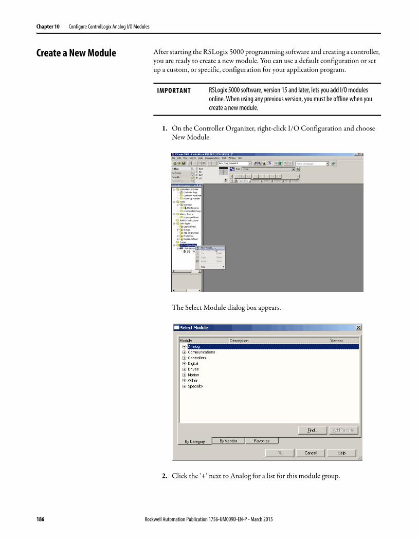
Chapter 10 Configure ControlLogix Analog I/O Modules
Create a New Module After starting the RSLogix 5000 programming software and creating a controller, you are ready to create a new module. You can use a default configuration or set up a custom, or specific, configuration for your application program.
1. On the Controller Organizer, right-click I/O Configuration and choose New Module.
The Select Module dialog box appears.
2. Click the ‘+’ next to Analog for a list for this module group.
IMPORTANT RSLogix 5000 software, version 15 and later, lets you add I/O modules online. When using any previous version, you must be offline when you create a new module.
186 Rockwell Automation Publication 1756-UM009D-EN-P - March 2015
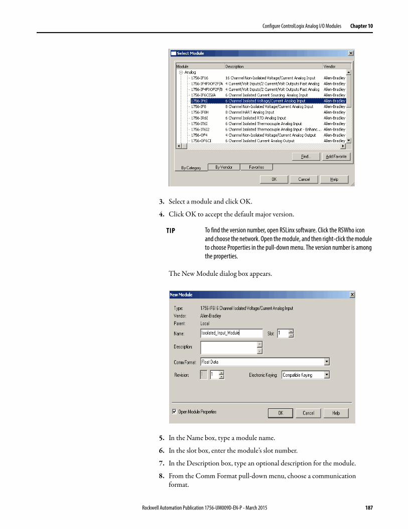
Configure ControlLogix Analog I/O Modules Chapter 10
3. Select a module and click OK.
4. Click OK to accept the default major version.
The New Module dialog box appears.
5. In the Name box, type a module name.
6. In the slot box, enter the module’s slot number.
7. In the Description box, type an optional description for the module.
8. From the Comm Format pull-down menu, choose a communication format.
TIP To find the version number, open RSLinx software. Click the RSWho icon and choose the network. Open the module, and then right-click the module to choose Properties in the pull-down menu. The version number is among the properties.
Rockwell Automation Publication 1756-UM009D-EN-P - March 2015 187
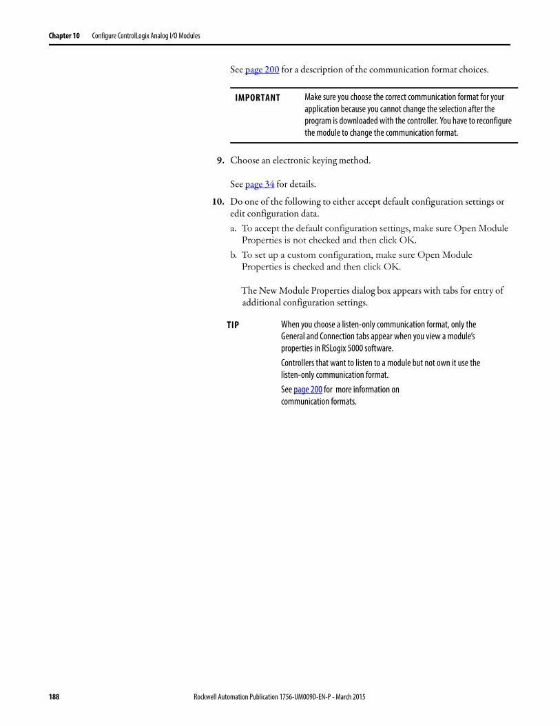
Chapter 10 Configure ControlLogix Analog I/O Modules
See page 200 for a description of the communication format choices.
9. Choose an electronic keying method.
See page 34 for details.
10. Do one of the following to either accept default configuration settings or edit configuration data.a. To accept the default configuration settings, make sure Open Module
Properties is not checked and then click OK.
b. To set up a custom configuration, make sure Open Module Properties is checked and then click OK.
The New Module Properties dialog box appears with tabs for entry of additional configuration settings.
IMPORTANT Make sure you choose the correct communication format for your application because you cannot change the selection after the program is downloaded with the controller. You have to reconfigure the module to change the communication format.
TIP When you choose a listen-only communication format, only the General and Connection tabs appear when you view a module’s properties in RSLogix 5000 software.Controllers that want to listen to a module but not own it use the listen-only communication format.See page 200 for more information oncommunication formats.
188 Rockwell Automation Publication 1756-UM009D-EN-P - March 2015
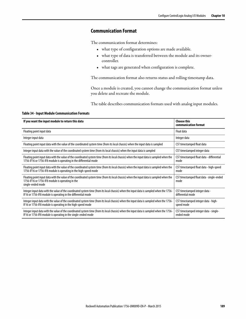
Configure ControlLogix Analog I/O Modules Chapter 10
Communication Format
The communication format determines:• what type of configuration options are made available.• what type of data is transferred between the module and its owner-
controller.• what tags are generated when configuration is complete.
The communication format also returns status and rolling timestamp data.
Once a module is created, you cannot change the communication format unless you delete and recreate the module.
The table describes communication formats used with analog input modules.
Table 34 - Input Module Communication Formats
If you want the input module to return this data Choose thiscommunication format
Floating point input data Float data
Integer input data Integer data
Floating point input data with the value of the coordinated system time (from its local chassis) when the input data is sampled CST timestamped float data
Integer input data with the value of the coordinated system time (from its local chassis) when the input data is sampled CST timestamped integer data
Floating point input data with the value of the coordinated system time (from its local chassis) when the input data is sampled when the 1756-IF16 or 1756-IF8 module is operating in the differential mode
CST timestamped float data - differential mode
Floating point input data with the value of the coordinated system time (from its local chassis) when the input data is sampled when the 1756-IF16 or 1756-IF8 module is operating in the high-speed mode
CST timestamped float data - high-speed mode
Floating point input data with the value of the coordinated system time (from its local chassis) when the input data is sampled when the 1756-IF16 or 1756-IF8 module is operating in thesingle-ended mode
CST timestamped float data - single-ended mode
Integer input data with the value of the coordinated system time (from its local chassis) when the input data is sampled when the 1756-IF16 or 1756-IF8 module is operating in the differential mode
CST timestamped integer data - differential mode
Integer input data with the value of the coordinated system time (from its local chassis) when the input data is sampled when the 1756-IF16 or 1756-IF8 module is operating in the high-speed mode
CST timestamped integer data - high-speed mode
Integer input data with the value of the coordinated system time (from its local chassis) when the input data is sampled when the 1756-IF16 or 1756-IF8 module is operating in the single-ended mode
CST timestamped integer data - single-ended mode
Rockwell Automation Publication 1756-UM009D-EN-P - March 2015 189
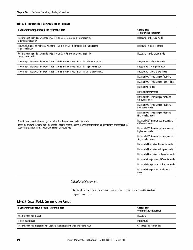
Chapter 10 Configure ControlLogix Analog I/O Modules
Output Module Formats
The table describes the communication formats used with analogoutput modules.
Floating point input data when the 1756-IF16 or 1756-IF8 module is operating in thedifferential mode only
Float data - differential mode
Returns floating point input data when the 1756-IF16 or 1756-IF8 module is operating in thehigh-speed mode
Float data - high-speed mode
Floating point input data when the 1756-IF16 or 1756-IF8 module is operating in thesingle-ended mode
Float data - single-ended mode
Integer input data when the 1756-IF16 or 1756-IF8 module is operating in the differential mode Integer data - differential mode
Integer input data when the 1756-IF16 or 1756-IF8 module is operating in the high-speed mode Integer data - high-speed mode
Integer input data when the 1756-IF16 or 1756-IF8 module is operating in the single-ended mode Integer data - single-ended mode
Specific input data that is used by a controller that does not own the input moduleThese choices have the same definition as the similarly-named options above except that they represent listen-only connections between the analog input module and a listen-only controller
Listen only CST timestamped float data
Listen only CST timestamped integer data
Listen only float data
Listen only integer data
Listen only CST timestamped float data - differential mode
Listen only CST timestamped float data - high-speed mode
Listen only CST timestamped float data - single-ended mode
Listen only CST timestamped integer data - differential mode
Listen only CST timestamped integer data - high-speed mode
Listen only CST timestamped integer data - single-ended mode
Listen only Float data - differential mode
Listen only Float data - high-speed mode
Listen only Float data - single-ended mode
Listen only Integer data - differential mode
Listen only Integer data - high-speed mode
Listen only Integer data - single-ended mode
Table 34 - Input Module Communication Formats
If you want the input module to return this data Choose thiscommunication format
Table 35 - Output Module Communication Formats
If you want the output module return this data Choose thiscommunications format
Floating point output data Float data
Integer output data Integer data
Floating point output data and receives data echo values with a CST timestamp value CST timestamped float data
190 Rockwell Automation Publication 1756-UM009D-EN-P - March 2015
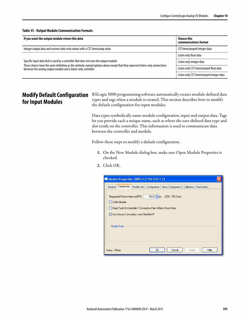
Configure ControlLogix Analog I/O Modules Chapter 10
Modify Default Configurationfor Input Modules
RSLogix 5000 programming software automatically creates module-defined data types and tags when a module is created. This section describes how to modify the default configuration for input modules.
Data types symbolically name module configuration, input and output data. Tags let you provide each a unique name, such as where the user-defined data type and slot reside on the controller. This information is used to communicate data between the controller and module.
Follow these steps to modify a default configuration.
1. On the New Module dialog box, make sure Open Module Properties is checked.
2. Click OK.
Integer output data and receives data echo values with a CST timestamp value CST timestamped integer data
Specific input data that is used by a controller that does not own the output moduleThese choices have the same definition as the similarly-named options above except that they represent listen-only connections between the analog output module and a listen-only controller
Listen only float data
Listen only integer data
Listen only CST timestamped float data
Listen only CST timestamped integer data
Table 35 - Output Module Communication Formats
If you want the output module return this data Choose thiscommunications format
Rockwell Automation Publication 1756-UM009D-EN-P - March 2015 191
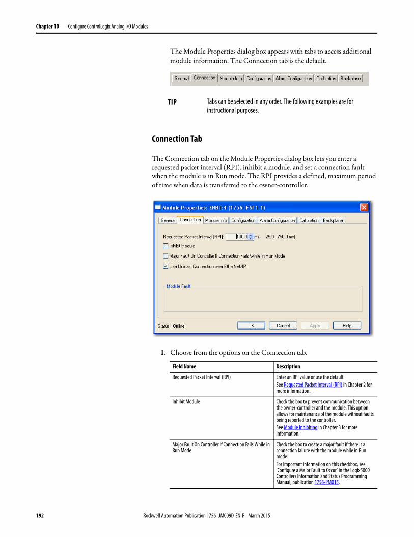
Chapter 10 Configure ControlLogix Analog I/O Modules
The Module Properties dialog box appears with tabs to access additional module information. The Connection tab is the default.
Connection Tab
The Connection tab on the Module Properties dialog box lets you enter a requested packet interval (RPI), inhibit a module, and set a connection fault when the module is in Run mode. The RPI provides a defined, maximum period of time when data is transferred to the owner-controller.
1. Choose from the options on the Connection tab.
TIP Tabs can be selected in any order. The following examples are for instructional purposes.
Field Name Description
Requested Packet Interval (RPI) Enter an RPI value or use the default.See Requested Packet Interval (RPI) in Chapter 2 for more information.
Inhibit Module Check the box to prevent communication between the owner-controller and the module. This option allows for maintenance of the module without faults being reported to the controller.See Module Inhibiting in Chapter 3 for more information.
Major Fault On Controller If Connection Fails While in Run Mode
Check the box to create a major fault if there is a connection failure with the module while in Run mode.For important information on this checkbox, see ‘Configure a Major Fault to Occur’ in the Logix5000 Controllers Information and Status Programming Manual, publication 1756-PM015.
192 Rockwell Automation Publication 1756-UM009D-EN-P - March 2015
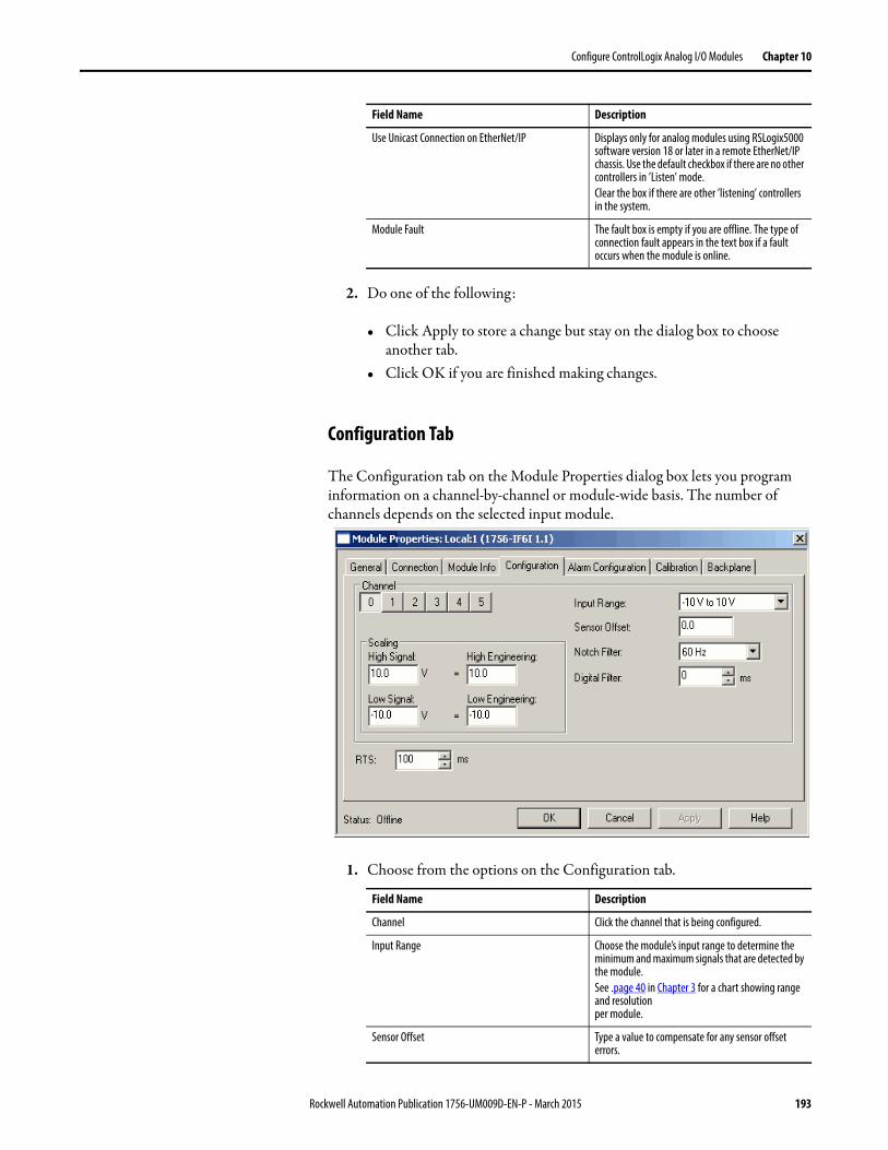
Configure ControlLogix Analog I/O Modules Chapter 10
2. Do one of the following:
• Click Apply to store a change but stay on the dialog box to choose another tab.
• Click OK if you are finished making changes.
Configuration Tab
The Configuration tab on the Module Properties dialog box lets you program information on a channel-by-channel or module-wide basis. The number of channels depends on the selected input module.
1. Choose from the options on the Configuration tab.
Use Unicast Connection on EtherNet/IP Displays only for analog modules using RSLogix5000 software version 18 or later in a remote EtherNet/IP chassis. Use the default checkbox if there are no other controllers in ’Listen’ mode.Clear the box if there are other ’listening’ controllers in the system.
Module Fault The fault box is empty if you are offline. The type of connection fault appears in the text box if a fault occurs when the module is online.
Field Name Description
Channel Click the channel that is being configured.
Input Range Choose the module’s input range to determine the minimum and maximum signals that are detected by the module.See .page 40 in Chapter 3 for a chart showing range and resolutionper module.
Sensor Offset Type a value to compensate for any sensor offset errors.
Field Name Description
Rockwell Automation Publication 1756-UM009D-EN-P - March 2015 193
Chapter 10 Configure ControlLogix Analog I/O Modules
2. After the channels are configured, do one of the following:
• Click Apply to store a change but stay on the dialog box to choose another tab.
• Click OK if you are finished making changes.
Notch Filter Use the default (60 Hz) or choose a frequency that attenuates the input signal at this specified frequency.
Digital Filter Choose a value in milliseconds that specifies the time constant for a digital first order lag filter on the input. A value of 0 disables the filter.See page 54 in Chapter 4 for an amplitude chart example.
Scaling You can scale only with the floating point data format. Scaling lets you configure two points in the module’s operating range with the associated low and high points for this range.See page 42 in Chapter 3 for details.
RTS Choose a value in milliseconds that the module performs a Real Time Sample (RTS). This parameter determines when the module scans all input channels, stores data into memory, and multicasts the update channel data.Note: If the RTS value is less than or equal to the RPI, each multicast of data from the module has updated channel information. If the RTS value is greater than the RPI, the module multicats at both the RTS value and the RPI rate.The module resets the RPI timer each time an RTS is performed.
IMPORTANT The 1756-IR6I, 1756-IT6I, and 1756-IT6I2 modules have additional configurations, such as temperature units and cold option junctions. See page 198 and page 199 for dialog box examples.
Field Name Description
194 Rockwell Automation Publication 1756-UM009D-EN-P - March 2015
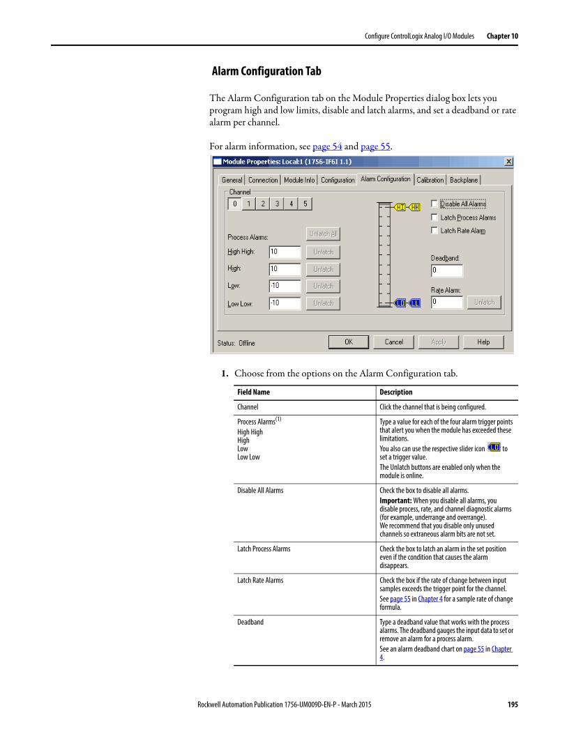
Configure ControlLogix Analog I/O Modules Chapter 10
Alarm Configuration Tab
The Alarm Configuration tab on the Module Properties dialog box lets you program high and low limits, disable and latch alarms, and set a deadband or rate alarm per channel.
For alarm information, see page 54 and page 55.
1. Choose from the options on the Alarm Configuration tab.
Field Name Description
Channel Click the channel that is being configured.
Process Alarms(1)
High HighHighLowLow Low
Type a value for each of the four alarm trigger points that alert you when the module has exceeded these limitations.You also can use the respective slider icon to set a trigger value.The Unlatch buttons are enabled only when the module is online.
Disable All Alarms Check the box to disable all alarms.Important: When you disable all alarms, you disable process, rate, and channel diagnostic alarms (for example, underrange and overrange). We recommend that you disable only unused channels so extraneous alarm bits are not set.
Latch Process Alarms Check the box to latch an alarm in the set position even if the condition that causes the alarm disappears.
Latch Rate Alarms Check the box if the rate of change between input samples exceeds the trigger point for the channel.See page 55 in Chapter 4 for a sample rate of change formula.
Deadband Type a deadband value that works with the process alarms. The deadband gauges the input data to set or remove an alarm for a process alarm.See an alarm deadband chart on page 55 in Chapter 4.
Rockwell Automation Publication 1756-UM009D-EN-P - March 2015 195
Chapter 10 Configure ControlLogix Analog I/O Modules
2. After the channels are configured, do one of the following:
• Click Apply to store a change but stay on the dialog box to choose another tab.
• Click OK to apply the change and close the dialog box.• Click Cancel to close the dialog box without applying changes.
Rate Alarm(2) Type a value used to determine the rate of change to trigger a rate alarm.
(1) Process alarms are not available in integer mode or in applications by using the 1756-IF16 module in the single-ended, floating point mode. The values for each limit are entered in scaledengineering units.
(2) Rate alarms are not available in integer mode or in applications by using the 1756-IF16 module in the single-ended, floating point mode. The values for each limit are entered in scaledengineering units.
Field Name Description
196 Rockwell Automation Publication 1756-UM009D-EN-P - March 2015
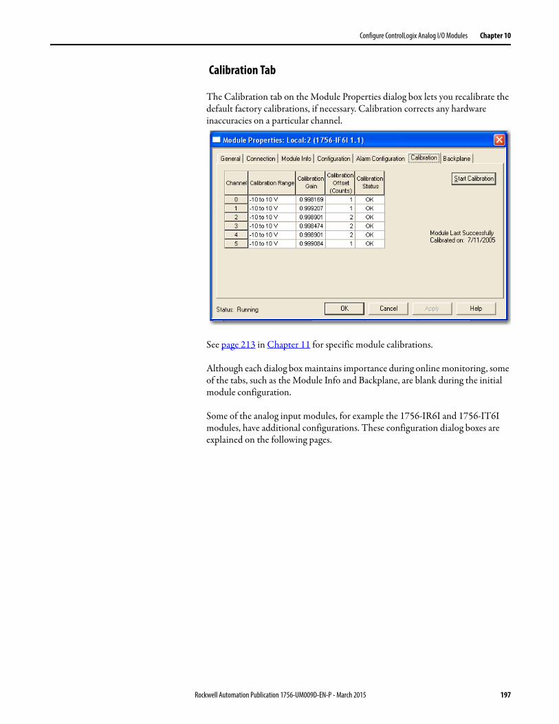
Configure ControlLogix Analog I/O Modules Chapter 10
Calibration Tab
The Calibration tab on the Module Properties dialog box lets you recalibrate the default factory calibrations, if necessary. Calibration corrects any hardware inaccuracies on a particular channel.
See page 213 in Chapter 11 for specific module calibrations.
Although each dialog box maintains importance during online monitoring, some of the tabs, such as the Module Info and Backplane, are blank during the initial module configuration.
Some of the analog input modules, for example the 1756-IR6I and 1756-IT6I modules, have additional configurations. These configuration dialog boxes are explained on the following pages.
Rockwell Automation Publication 1756-UM009D-EN-P - March 2015 197
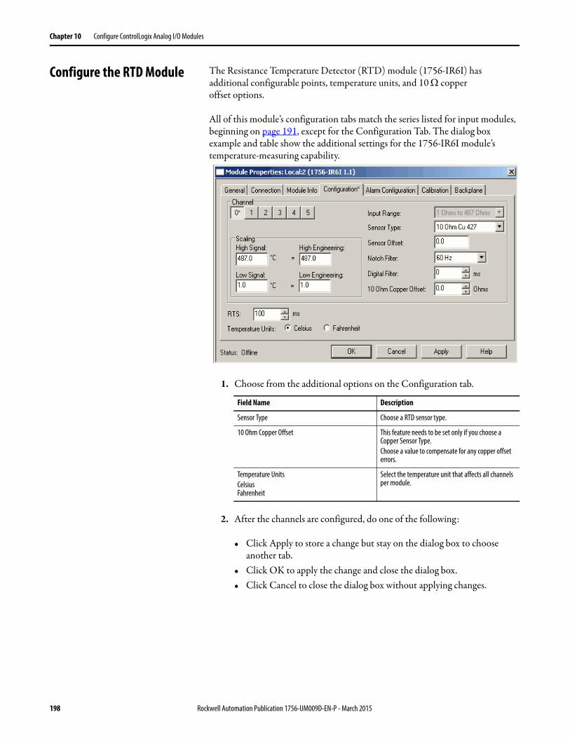
Chapter 10 Configure ControlLogix Analog I/O Modules
Configure the RTD Module The Resistance Temperature Detector (RTD) module (1756-IR6I) has additional configurable points, temperature units, and 10 copperoffset options.
All of this module’s configuration tabs match the series listed for input modules, beginning on page 191, except for the Configuration Tab. The dialog box example and table show the additional settings for the 1756-IR6I module’s temperature-measuring capability.
1. Choose from the additional options on the Configuration tab.
2. After the channels are configured, do one of the following:
• Click Apply to store a change but stay on the dialog box to choose another tab.
• Click OK to apply the change and close the dialog box.• Click Cancel to close the dialog box without applying changes.
Field Name Description
Sensor Type Choose a RTD sensor type.
10 Ohm Copper Offset This feature needs to be set only if you choose a Copper Sensor Type.Choose a value to compensate for any copper offset errors.
Temperature UnitsCelsiusFahrenheit
Select the temperature unit that affects all channels per module.
198 Rockwell Automation Publication 1756-UM009D-EN-P - March 2015
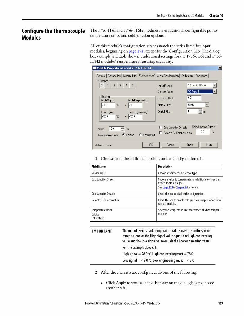
Configure ControlLogix Analog I/O Modules Chapter 10
Configure the Thermocouple Modules
The 1756-IT6I and 1756-IT6I2 modules have additional configurable points, temperature units, and cold junction options.
All of this module’s configuration screens match the series listed for input modules, beginning on page 191, except for the Configuration Tab. The dialog box example and table show the additional settings for the 1756-IT6I and 1756-IT6I2 modules’ temperature-measuring capability.
1. Choose from the additional options on the Configuration tab.
2. After the channels are configured, do one of the following:
• Click Apply to store a change but stay on the dialog box to choose another tab.
Field Name Description
Sensor Type Choose a thermocouple sensor type.
Cold Junction Offset Choose a value to compensate for additional voltage that effects the input signal.See page 119 in Chapter 6 for details.
Cold Junction Disable Check the box to disable the cold junction.
Remote CJ Compensation Check the box to enable cold junction compensation for a remote module.
Temperature UnitsCelsiusFahrenheit
Select the temperature unit that affects all channels per module.
IMPORTANT The module sends back temperature values over the entire sensor range as long as the High signal value equals the High engineering value and the Low signal value equals the Low engineering value.For the example above, if:High signal = 78.0 °C, High engineering must = 78.0.Low signal = -12.0 °C, Low engineering must = -12.0
Rockwell Automation Publication 1756-UM009D-EN-P - March 2015 199
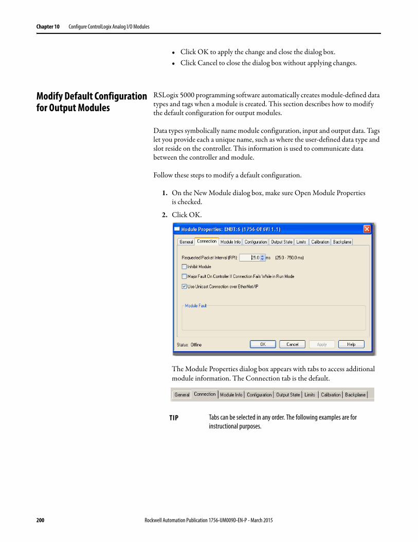
Chapter 10 Configure ControlLogix Analog I/O Modules
• Click OK to apply the change and close the dialog box.• Click Cancel to close the dialog box without applying changes.
Modify Default Configurationfor Output Modules
RSLogix 5000 programming software automatically creates module-defined data types and tags when a module is created. This section describes how to modify the default configuration for output modules.
Data types symbolically name module configuration, input and output data. Tags let you provide each a unique name, such as where the user-defined data type and slot reside on the controller. This information is used to communicate data between the controller and module.
Follow these steps to modify a default configuration.
1. On the New Module dialog box, make sure Open Module Propertiesis checked.
2. Click OK.
The Module Properties dialog box appears with tabs to access additional module information. The Connection tab is the default.
TIP Tabs can be selected in any order. The following examples are for instructional purposes.
200 Rockwell Automation Publication 1756-UM009D-EN-P - March 2015
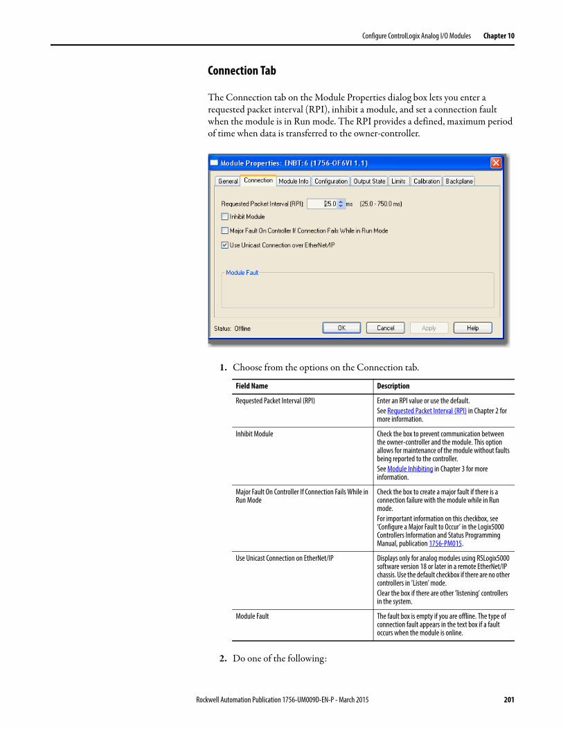
Configure ControlLogix Analog I/O Modules Chapter 10
Connection Tab
The Connection tab on the Module Properties dialog box lets you enter a requested packet interval (RPI), inhibit a module, and set a connection fault when the module is in Run mode. The RPI provides a defined, maximum period of time when data is transferred to the owner-controller.
1. Choose from the options on the Connection tab.
2. Do one of the following:
Field Name Description
Requested Packet Interval (RPI) Enter an RPI value or use the default.See Requested Packet Interval (RPI) in Chapter 2 for more information.
Inhibit Module Check the box to prevent communication between the owner-controller and the module. This option allows for maintenance of the module without faults being reported to the controller.See Module Inhibiting in Chapter 3 for more information.
Major Fault On Controller If Connection Fails While in Run Mode
Check the box to create a major fault if there is a connection failure with the module while in Run mode.For important information on this checkbox, see ‘Configure a Major Fault to Occur’ in the Logix5000 Controllers Information and Status Programming Manual, publication 1756-PM015.
Use Unicast Connection on EtherNet/IP Displays only for analog modules using RSLogix5000 software version 18 or later in a remote EtherNet/IP chassis. Use the default checkbox if there are no other controllers in ’Listen’ mode.Clear the box if there are other ’listening’ controllers in the system.
Module Fault The fault box is empty if you are offline. The type of connection fault appears in the text box if a fault occurs when the module is online.
Rockwell Automation Publication 1756-UM009D-EN-P - March 2015 201
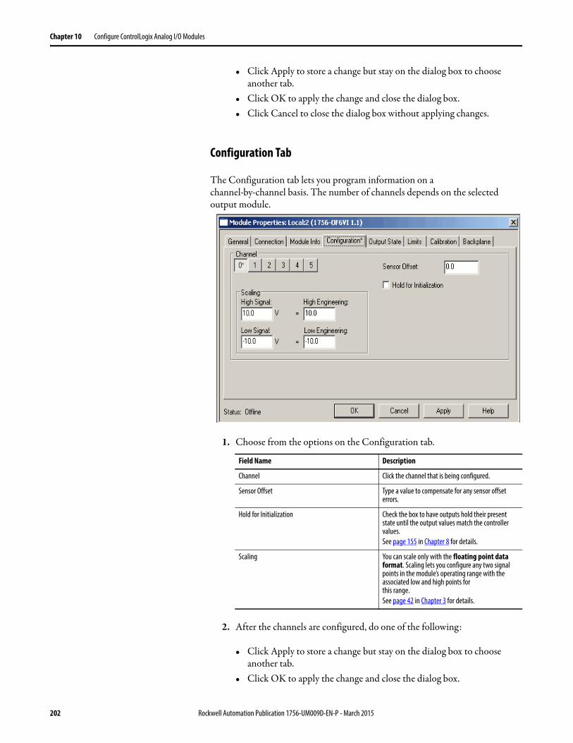
Chapter 10 Configure ControlLogix Analog I/O Modules
• Click Apply to store a change but stay on the dialog box to choose another tab.
• Click OK to apply the change and close the dialog box.• Click Cancel to close the dialog box without applying changes.
Configuration Tab
The Configuration tab lets you program information on a channel-by-channel basis. The number of channels depends on the selected output module.
1. Choose from the options on the Configuration tab.
2. After the channels are configured, do one of the following:
• Click Apply to store a change but stay on the dialog box to choose another tab.
• Click OK to apply the change and close the dialog box.
Field Name Description
Channel Click the channel that is being configured.
Sensor Offset Type a value to compensate for any sensor offset errors.
Hold for Initialization Check the box to have outputs hold their present state until the output values match the controller values.See page 155 in Chapter 8 for details.
Scaling You can scale only with the floating point data format. Scaling lets you configure any two signal points in the module’s operating range with the associated low and high points forthis range.See page 42 in Chapter 3 for details.
202 Rockwell Automation Publication 1756-UM009D-EN-P - March 2015
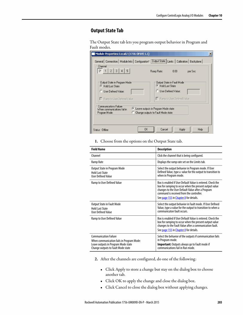
Configure ControlLogix Analog I/O Modules Chapter 10
Output State Tab
The Output State tab lets you program output behavior in Program andFault modes.
1. Choose from the options on the Output State tab.
2. After the channels are configured, do one of the following:
• Click Apply to store a change but stay on the dialog box to choose another tab.
• Click OK to apply the change and close the dialog box.• Click Cancel to close the dialog box without applying changes.
Field Name Description
Channel Click the channel that is being configured.
Ramp Rate Displays the ramp rate set on the Limits tab.
Output State in Program ModeHold Last StateUser Defined Value
Select the output behavior in Program mode. If User Defined Value, type a value for the output to transition to when in Program mode.
Ramp to User Defined Value Box is enabled if User Default Value is entered. Check the box for ramping to occur when the present output value changes to the User Default Value after a Program command is received from the controller.See page 155 in Chapter 8 for details.
Output State in Fault ModeHold Last StateUser Defined Value
Select the output behavior in Fault mode. If User Defined Value, type a value for the output to transition to when a communicaton fault occurs.
Ramp to User Defined Value Box is enabled if User Default Value is entered. Check the box for ramping to occur when the present output value changes to the Fault Value after a communication fault.See page 155 in Chapter 8 for details.
Communication FailureWhen communication fails in Program Mode:Leave outputs in Program Mode stateChange outputs to Fault Mode state
Select the behavior of the outputs if communication fails in Program mode.Important: Outputs always go to Fault mode if communications fail in Run mode.
Rockwell Automation Publication 1756-UM009D-EN-P - March 2015 203
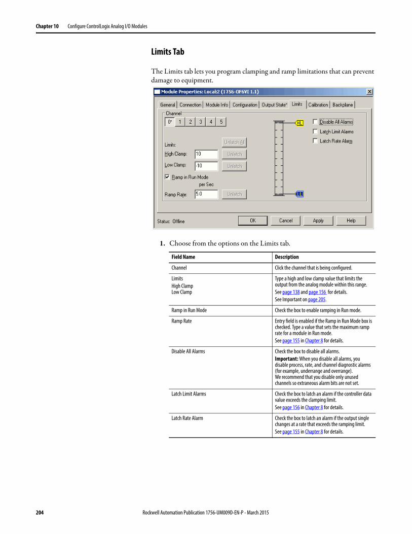
Chapter 10 Configure ControlLogix Analog I/O Modules
Limits Tab
The Limits tab lets you program clamping and ramp limitations that can prevent damage to equipment.
1. Choose from the options on the Limits tab.
Field Name Description
Channel Click the channel that is being configured.
LimitsHigh ClampLow Clamp
Type a high and low clamp value that limits the output from the analog module within this range.See page 138 and page 156 for details.See Important on page 205.
Ramp in Run Mode Check the box to enable ramping in Run mode.
Ramp Rate Entry field is enabled if the Ramp in Run Mode box is checked. Type a value that sets the maximum ramp rate for a module in Run mode.See page 155 in Chapter 8 for details.
Disable All Alarms Check the box to disable all alarms.Important: When you disable all alarms, you disable process, rate, and channel diagnostic alarms (for example, underrange and overrange). We recommend that you disable only unused channels so extraneous alarm bits are not set.
Latch Limit Alarms Check the box to latch an alarm if the controller data value exceeds the clamping limit.See page 156 in Chapter 8 for details.
Latch Rate Alarm Check the box to latch an alarm if the output single changes at a rate that exceeds the ramping limit.See page 155 in Chapter 8 for details.
204 Rockwell Automation Publication 1756-UM009D-EN-P - March 2015
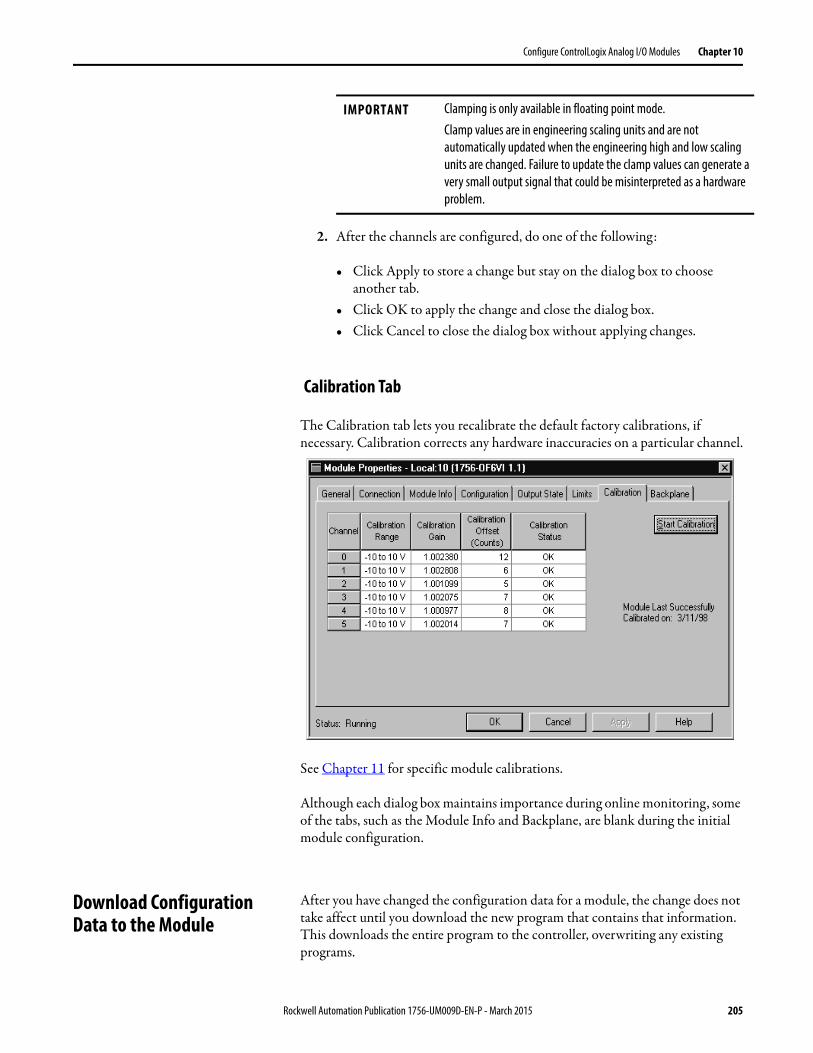
Configure ControlLogix Analog I/O Modules Chapter 10
2. After the channels are configured, do one of the following:
• Click Apply to store a change but stay on the dialog box to choose another tab.
• Click OK to apply the change and close the dialog box.• Click Cancel to close the dialog box without applying changes.
Calibration Tab
The Calibration tab lets you recalibrate the default factory calibrations, if necessary. Calibration corrects any hardware inaccuracies on a particular channel.
See Chapter 11 for specific module calibrations.
Although each dialog box maintains importance during online monitoring, some of the tabs, such as the Module Info and Backplane, are blank during the initial module configuration.
Download ConfigurationData to the Module
After you have changed the configuration data for a module, the change does not take affect until you download the new program that contains that information. This downloads the entire program to the controller, overwriting any existing programs.
IMPORTANT Clamping is only available in floating point mode.Clamp values are in engineering scaling units and are not automatically updated when the engineering high and low scaling units are changed. Failure to update the clamp values can generate a very small output signal that could be misinterpreted as a hardware problem.
Rockwell Automation Publication 1756-UM009D-EN-P - March 2015 205
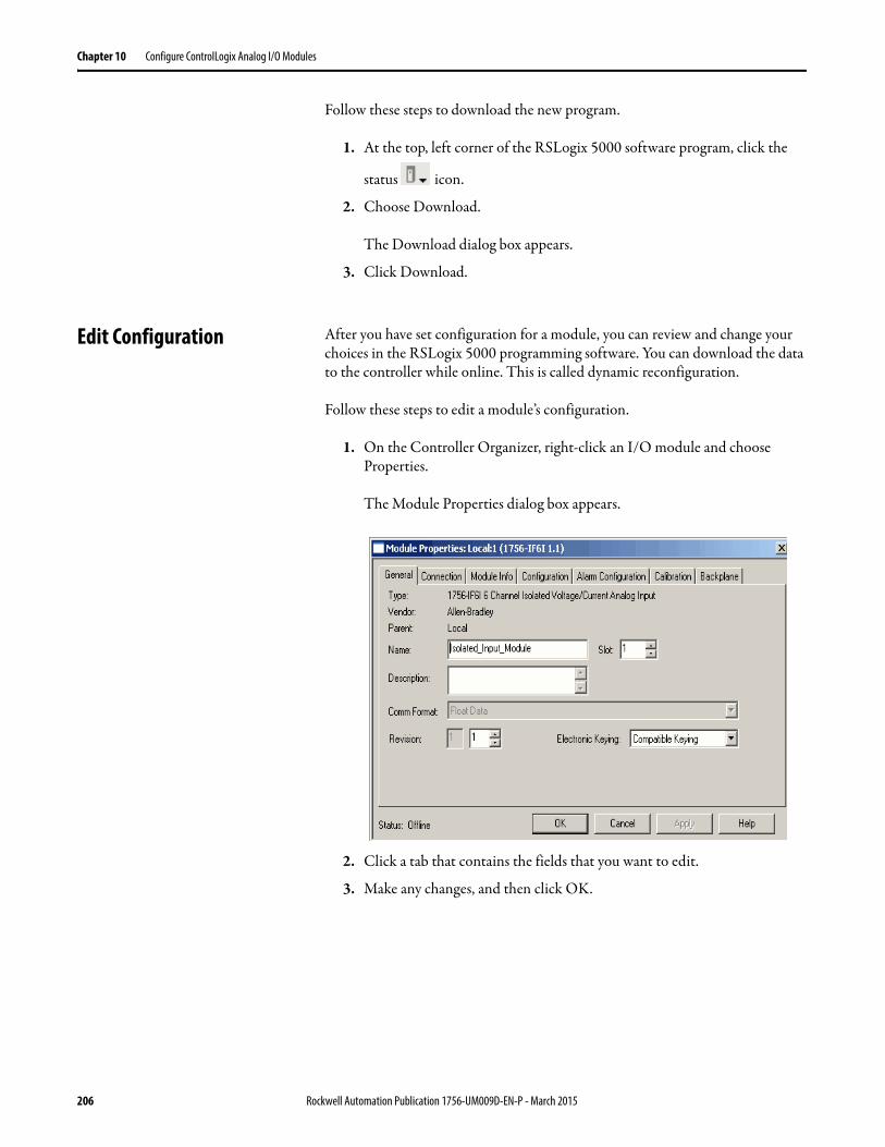
Chapter 10 Configure ControlLogix Analog I/O Modules
Follow these steps to download the new program.
1. At the top, left corner of the RSLogix 5000 software program, click the
status icon.
2. Choose Download.
The Download dialog box appears.
3. Click Download.
Edit Configuration After you have set configuration for a module, you can review and change your choices in the RSLogix 5000 programming software. You can download the data to the controller while online. This is called dynamic reconfiguration.
Follow these steps to edit a module’s configuration.
1. On the Controller Organizer, right-click an I/O module and choose Properties.
The Module Properties dialog box appears.
2. Click a tab that contains the fields that you want to edit.
3. Make any changes, and then click OK.
206 Rockwell Automation Publication 1756-UM009D-EN-P - March 2015
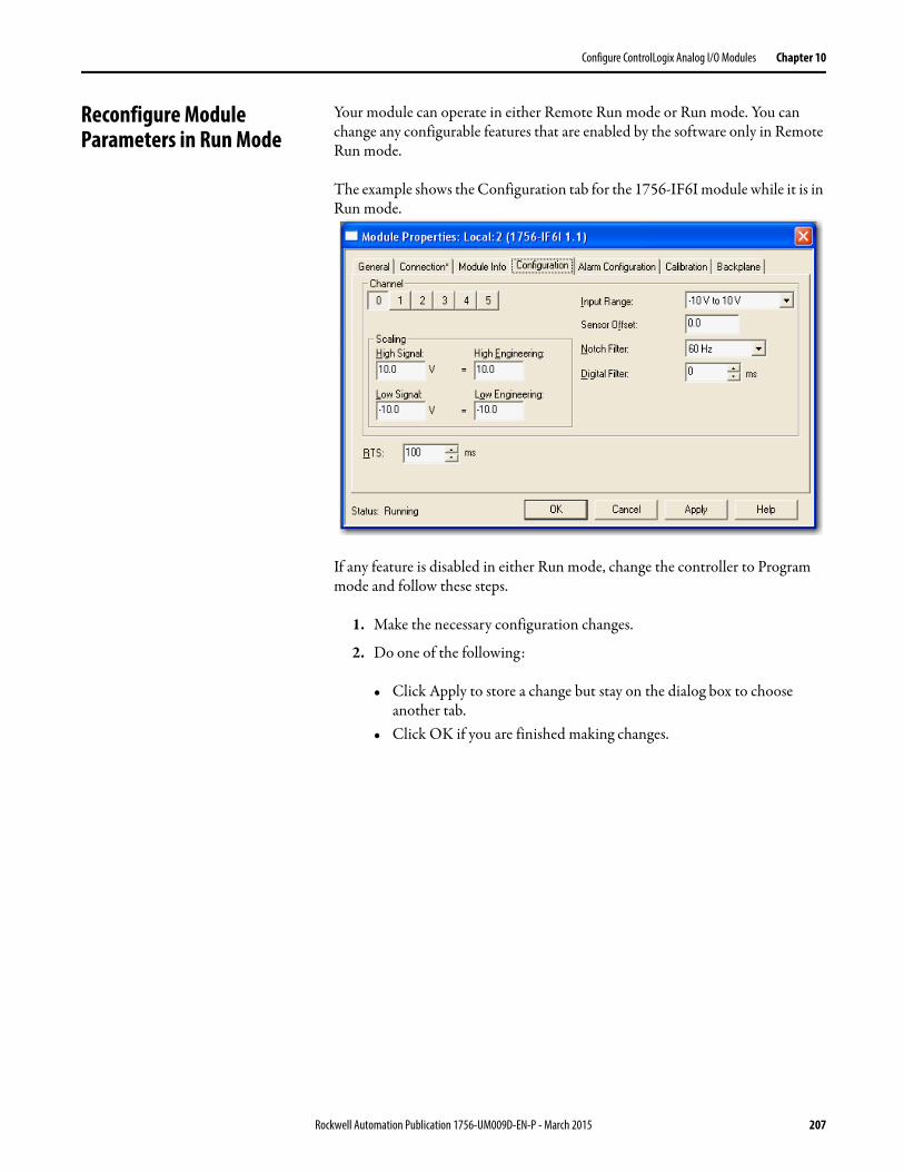
Configure ControlLogix Analog I/O Modules Chapter 10
Reconfigure Module Parameters in Run Mode
Your module can operate in either Remote Run mode or Run mode. You can change any configurable features that are enabled by the software only in Remote Run mode.
The example shows the Configuration tab for the 1756-IF6I module while it is in Run mode.
If any feature is disabled in either Run mode, change the controller to Program mode and follow these steps.
1. Make the necessary configuration changes.
2. Do one of the following:
• Click Apply to store a change but stay on the dialog box to choose another tab.
• Click OK if you are finished making changes.
Rockwell Automation Publication 1756-UM009D-EN-P - March 2015 207
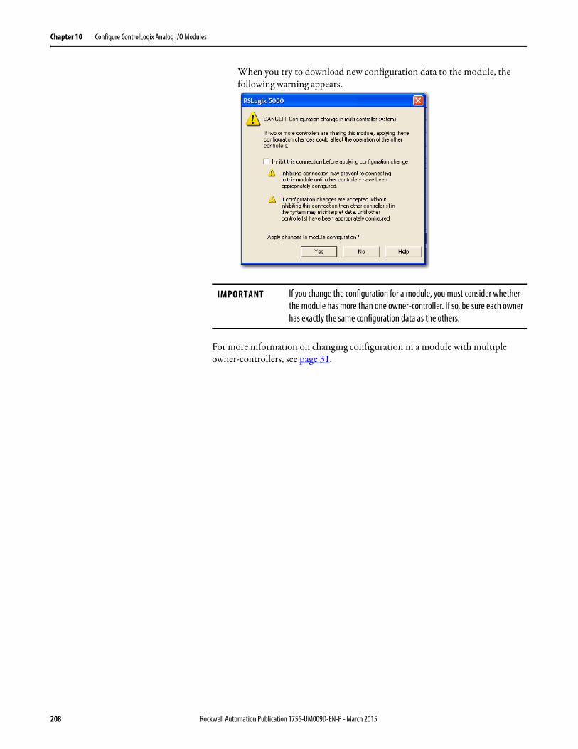
Chapter 10 Configure ControlLogix Analog I/O Modules
When you try to download new configuration data to the module, the following warning appears.
For more information on changing configuration in a module with multiple owner-controllers, see page 31.
IMPORTANT If you change the configuration for a module, you must consider whether the module has more than one owner-controller. If so, be sure each owner has exactly the same configuration data as the others.
208 Rockwell Automation Publication 1756-UM009D-EN-P - March 2015
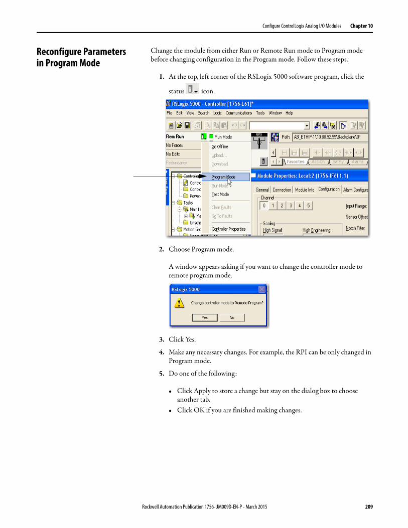
Configure ControlLogix Analog I/O Modules Chapter 10
Reconfigure Parametersin Program Mode
Change the module from either Run or Remote Run mode to Program mode before changing configuration in the Program mode. Follow these steps.
1. At the top, left corner of the RSLogix 5000 software program, click the
status icon.
2. Choose Program mode.
A window appears asking if you want to change the controller mode to remote program mode.
3. Click Yes.
4. Make any necessary changes. For example, the RPI can be only changed in Program mode.
5. Do one of the following:
• Click Apply to store a change but stay on the dialog box to choose another tab.
• Click OK if you are finished making changes.
Rockwell Automation Publication 1756-UM009D-EN-P - March 2015 209
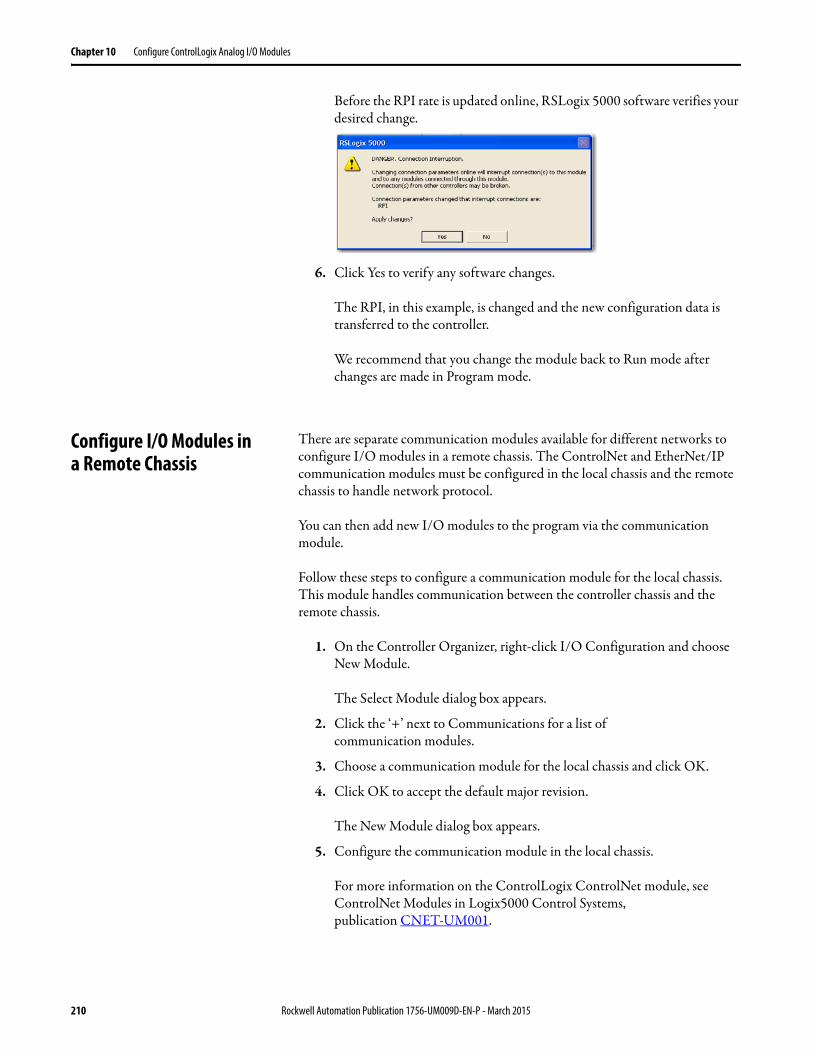
Chapter 10 Configure ControlLogix Analog I/O Modules
Before the RPI rate is updated online, RSLogix 5000 software verifies your desired change.
6. Click Yes to verify any software changes.
The RPI, in this example, is changed and the new configuration data is transferred to the controller.
We recommend that you change the module back to Run mode after changes are made in Program mode.
Configure I/O Modules ina Remote Chassis
There are separate communication modules available for different networks to configure I/O modules in a remote chassis. The ControlNet and EtherNet/IP communication modules must be configured in the local chassis and the remote chassis to handle network protocol.
You can then add new I/O modules to the program via the communication module.
Follow these steps to configure a communication module for the local chassis. This module handles communication between the controller chassis and the remote chassis.
1. On the Controller Organizer, right-click I/O Configuration and choose New Module.
The Select Module dialog box appears.
2. Click the ‘+’ next to Communications for a list ofcommunication modules.
3. Choose a communication module for the local chassis and click OK.
4. Click OK to accept the default major revision.
The New Module dialog box appears.
5. Configure the communication module in the local chassis.
For more information on the ControlLogix ControlNet module, see ControlNet Modules in Logix5000 Control Systems,publication CNET-UM001.
210 Rockwell Automation Publication 1756-UM009D-EN-P - March 2015
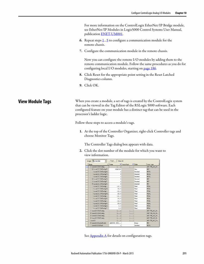
Configure ControlLogix Analog I/O Modules Chapter 10
For more information on the ControlLogix EtherNet/IP Bridge module, see EtherNet/IP Modules in Logix5000 Control Systems User Manual, publication ENET-UM001.
6. Repeat steps 1…5 to configure a communication module for theremote chassis.
7. Configure the communication module in the remote chassis.
Now you can configure the remote I/O modules by adding them to the remote communication module. Follow the same procedures as you do for configuring local I/O modules, starting on page 186.
8. Click Reset for the appropriate point setting in the Reset Latched Diagnostics column.
9. Click OK.
View Module Tags When you create a module, a set of tags is created by the ControlLogix system that can be viewed in the Tag Editor of the RSLogix 5000 software. Each configured feature on your module has a distinct tag that can be used in the processor’s ladder logic.
Follow these steps to access a module’s tags.
1. At the top of the Controller Organizer, right-click Controller tags and choose Monitor Tags.
The Controller Tags dialog box appears with data.
2. Click the slot number of the module for which you want toview information.
See Appendix A for details on configuration tags.
Rockwell Automation Publication 1756-UM009D-EN-P - March 2015 211

Chapter 10 Configure ControlLogix Analog I/O Modules
Notes:
212 Rockwell Automation Publication 1756-UM009D-EN-P - March 2015
Chapter 11
Calibrate the ControlLogix Analog I/O Modules
Introduction Your ControlLogix analog I/O module comes from the factory with a default calibration. You can choose to recalibrate your module to increase its accuracy for your specific application.
You do not have to configure a module before you calibrate it. If you decide to calibrate your analog I/O modules first, you must add them to your program.
This chapter describes how to calibrate ControlLogix analog modules.
Topic Page
Difference of Calibrating an Input Module and an Output Module 214
Calibrate Your Input Modules 215
Calibrate Your Output Modules 238
IMPORTANT Analog I/O modules can be calibrated on a channel by channel basis or with the channels grouped together. Regardless of which option you choose, we recommend you calibrate all channels on your module each time you calibrate. This helps you maintain consistent calibration readings and improve module accuracy.Calibration is meant to correct any hardware inaccuracies present on a particular channel. The calibration procedure compares a known standard, either input signal or recorded output, with the channel’s performance and then calculating a linear correction factor between the measured and the ideal.The linear calibration correction factor is applied on every input or output same to obtain maximum accuracy.
Rockwell Automation Publication 1756-UM009D-EN-P - March 2015 213
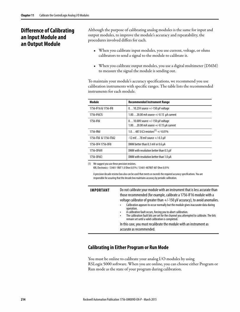
Chapter 11 Calibrate the ControlLogix Analog I/O Modules
Difference of Calibratingan Input Module andan Output Module
Although the purpose of calibrating analog modules is the same for input and output modules, to improve the module’s accuracy and repeatability, the procedures involved differs for each.
• When you calibrate input modules, you use current, voltage, or ohms calibrators to send a signal to the module to calibrate it.
• When you calibrate output modules, you use a digital multimeter (DMM) to measure the signal the module is sending out.
To maintain your module’s accuracy specifications, we recommend you use calibration instruments with specific ranges. The table lists the recommended instruments for each module.
Calibrating in Either Program or Run Mode
You must be online to calibrate your analog I/O modules by usingRSLogix 5000 software. When you are online, you can choose either Program or Run mode as the state of your program during calibration.
Module Recommended Instrument Range
1756-IF16 & 1756-IF8 0…10.25V source +/-150 μV voltage
1756-IF6CIS 1.00…20.00 mA source +/-0.15 μA current
1756-IF6I 0…10.00V source +/-150 μV voltage1.00…20.00 mA source +/-0.15 μA current
1756-IR6I 1.0…487.0 resistors(1) +/-0.01%
(1) We suggest you use these precision resistors.KRL Electronics - 534A1-1R0T 1.0 Ohm 0.01% / 534A1-487R0T 487 Ohm 0.01%
A precision decade resistor box also can be used that meets or exceeds the required accuracy specifications. You are responsible for assuring that the decade box maintains accuracy by periodic calibration.
1756-IT6I & 1756-IT6I2 -12 mV…78 mV source +/-0.3 μV
1756-OF4 1756-OF8 DMM better than 0.3 mV or 0.6 μA
1756-OF6VI DMM with resolution better than 0.5 μV
1756-OF6CI DMM with resolution better than 1.0 μA
IMPORTANT Do not calibrate your module with an instrument that is less accurate than those recommended (for example, calibrate a 1756-IF16 module with a voltage calibrator of greater than +/-150 μV accuracy), to avoid anomalies.• Calibration appears to occur normally but the module gives inaccurate data during
operation.• A calibration fault occurs, forcing you to abort calibration.• The calibration fault bits are set for the channel you attempted to calibrate. The bits
remain set until a valid calibration is completed.In this case, you must recalibrate the module with an instrument as accurate as recommended.
214 Rockwell Automation Publication 1756-UM009D-EN-P - March 2015
Calibrate the ControlLogix Analog I/O Modules Chapter 11
We recommend that your module be in Program mode and not be actively controlling a process when you calibrate it.
Calibrate Your Input Modules Input calibration is a multi-step process that involves multiple services being sent to the module. This section has four parts as shown in the table. Each input module requires attention be paid to specific calibration ranges.
Calibrating the 1756-IF16 or 1756-IF8 Modules
The 1756-IF16 or 1756-IF8 modules are used in applications requiring voltage or current. The modules offer four input ranges:
• -10…10V• 0…5V• 0…10V• 0…20 mA
However, you can only calibrate these modules using a voltage signal.
IMPORTANT The module freezes the state of each channel and does not update the controller with new data until after the calibration ends. This could be hazardous if active control were attempted during calibration.
Topic Page
Calibrating the 1756-IF16 or 1756-IF8 Modules 215
Calibrating the 1756-IF6CIS or 1756-IF6I Modules 221
Calibrating the 1756-IR6I 227
Calibrating the 1756-IT6I or 1756-IT6I2 232
IMPORTANT Regardless of what application range is selected prior to calibration, all calibration uses a +/-10V range.
Rockwell Automation Publication 1756-UM009D-EN-P - March 2015 215
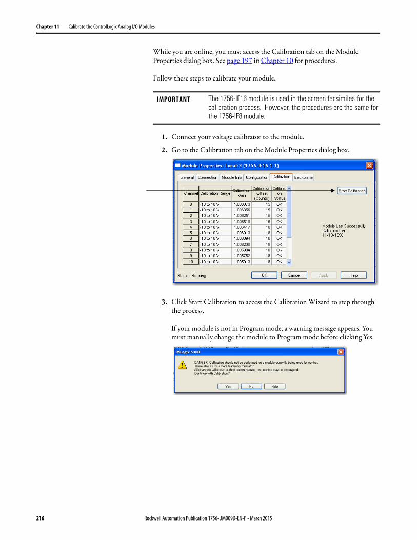
Chapter 11 Calibrate the ControlLogix Analog I/O Modules
While you are online, you must access the Calibration tab on the Module Properties dialog box. See page 197 in Chapter 10 for procedures.
Follow these steps to calibrate your module.
1. Connect your voltage calibrator to the module.
2. Go to the Calibration tab on the Module Properties dialog box.
3. Click Start Calibration to access the Calibration Wizard to step through the process.
If your module is not in Program mode, a warning message appears. You must manually change the module to Program mode before clicking Yes.
IMPORTANT The 1756-IF16 module is used in the screen facsimiles for the calibration process. However, the procedures are the same for the 1756-IF8 module.
216 Rockwell Automation Publication 1756-UM009D-EN-P - March 2015
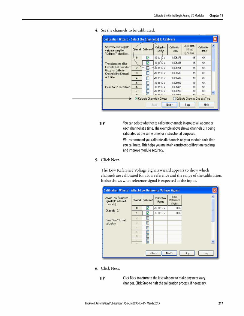
Calibrate the ControlLogix Analog I/O Modules Chapter 11
4. Set the channels to be calibrated.
5. Click Next.
The Low Reference Voltage Signals wizard appears to show which channels are calibrated for a low reference and the range of the calibration. It also shows what reference signal is expected at the input.
6. Click Next.
TIP You can select whether to calibrate channels in groups all at once or each channel at a time. The example above shows channels 0,1 being calibrated at the same time for instructional purposes.We recommend you calibrate all channels on your module each time you calibrate. This helps you maintain consistent calibration readings and improve module accuracy.
TIP Click Back to return to the last window to make any necessary changes. Click Stop to halt the calibration process, if necessary.
Rockwell Automation Publication 1756-UM009D-EN-P - March 2015 217
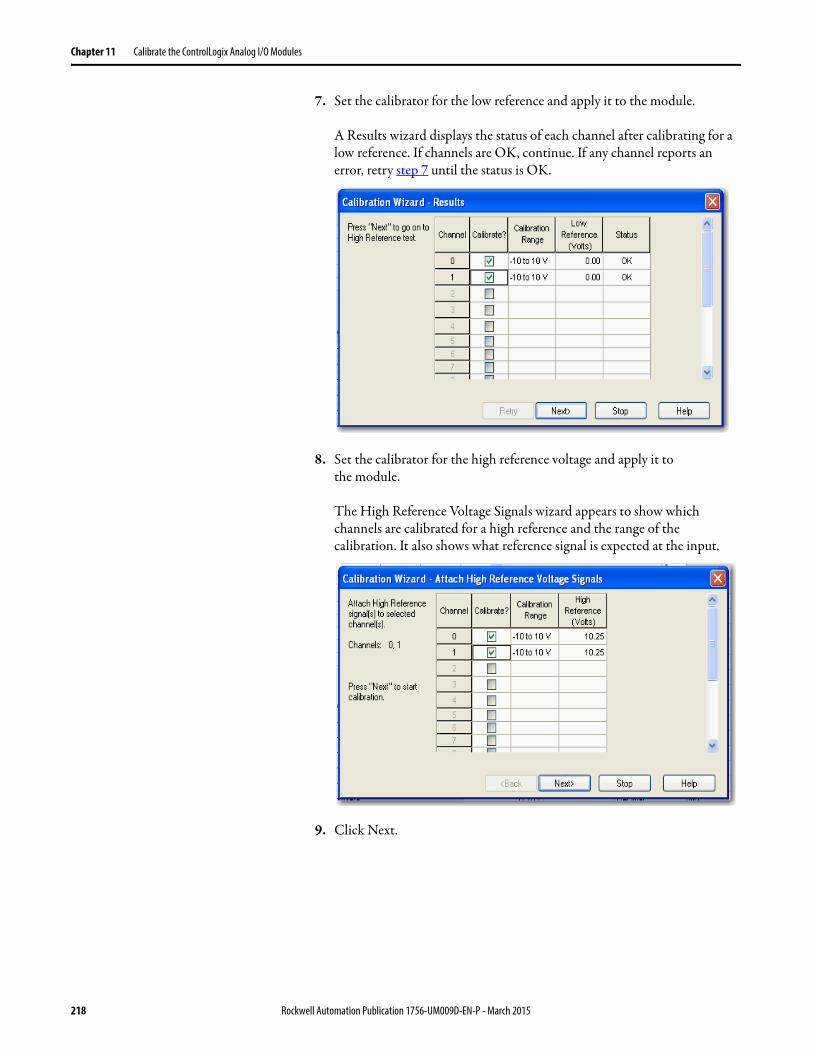
Chapter 11 Calibrate the ControlLogix Analog I/O Modules
7. Set the calibrator for the low reference and apply it to the module.
A Results wizard displays the status of each channel after calibrating for a low reference. If channels are OK, continue. If any channel reports an error, retry step 7 until the status is OK.
8. Set the calibrator for the high reference voltage and apply it tothe module.
The High Reference Voltage Signals wizard appears to show which channels are calibrated for a high reference and the range of the calibration. It also shows what reference signal is expected at the input.
9. Click Next.
218 Rockwell Automation Publication 1756-UM009D-EN-P - March 2015
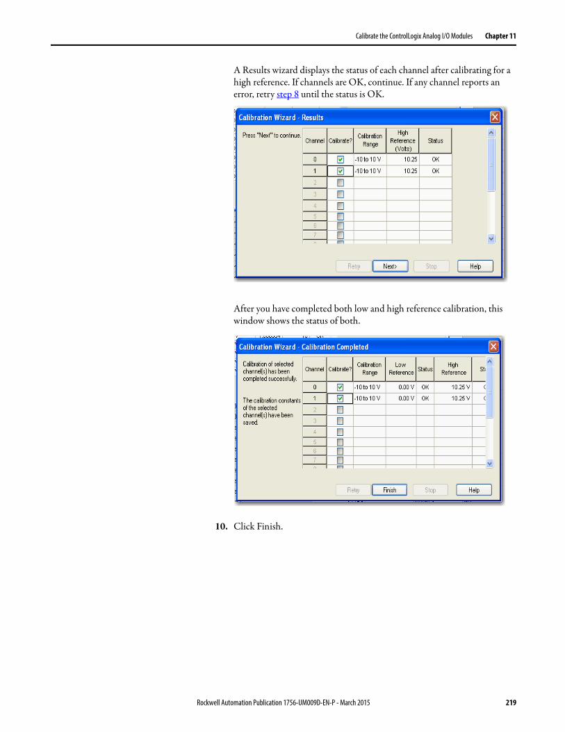
Calibrate the ControlLogix Analog I/O Modules Chapter 11
A Results wizard displays the status of each channel after calibrating for a high reference. If channels are OK, continue. If any channel reports an error, retry step 8 until the status is OK.
After you have completed both low and high reference calibration, this window shows the status of both.
10. Click Finish.
Rockwell Automation Publication 1756-UM009D-EN-P - March 2015 219
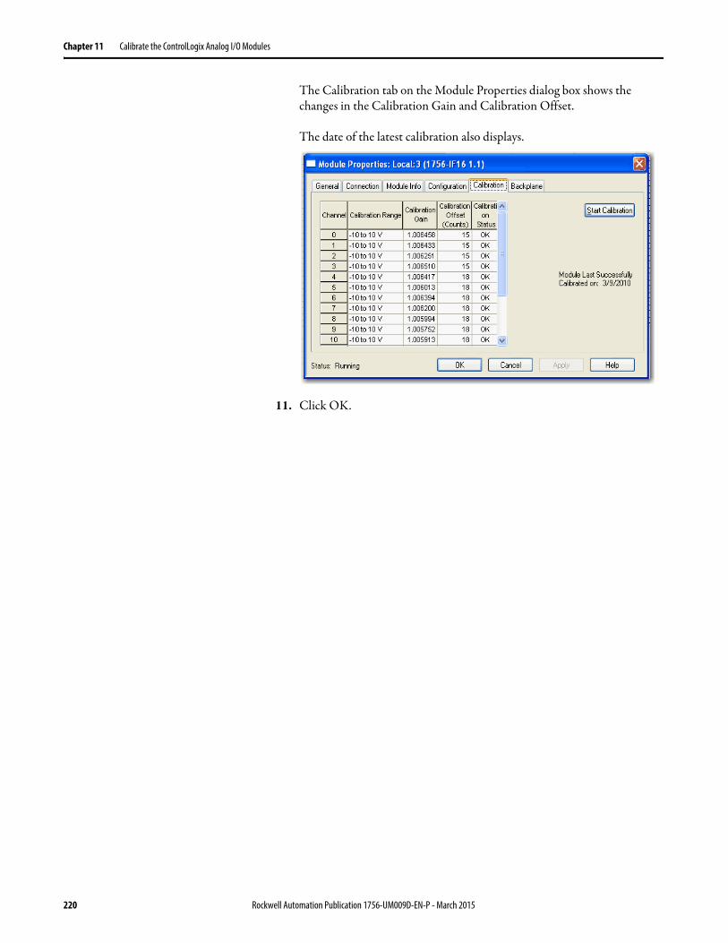
Chapter 11 Calibrate the ControlLogix Analog I/O Modules
The Calibration tab on the Module Properties dialog box shows the changes in the Calibration Gain and Calibration Offset.
The date of the latest calibration also displays.
11. Click OK.
220 Rockwell Automation Publication 1756-UM009D-EN-P - March 2015
Calibrate the ControlLogix Analog I/O Modules Chapter 11
Calibrating the 1756-IF6CIS or 1756-IF6I Modules
The 1756-IF6CIS module can be used for applications that require current only. The 1756-IF6I module can be used for applications requiring voltage or current. Calibrate the modules for your specific application.
Calibrating the 1756-IF6I for Voltage Applications
During 1756-IF6I module calibration, 0.0V and +10.0V external references are applied consecutively to the module’s terminals. The module records the deviation from these reference values (that is, 0.0V and +10.0V) and stores it as calibration constants in the module’s firmware. The internal calibration constants are then used in every subsequent signal conversion to compensate for circuit inaccuracies. The 0/10V user calibration compensates for all voltage ranges on the 1756-IF6I module (0-10V, +/-10V, and 0-5V) and compensates for inaccuracies of the module’s entire analog circuitry, including input amplifier, resistors, and the A/D convertor.
The 1756-IF6I offers 3 input voltage ranges:• -10…10V• 0…5V• 0…10V
Calibrating the 1756-IF6CIS or 1756-IF6I for Current Applications
The 1756-IF6CIS and 1756-IF6I modules offer a 0…20 mA current range. Calibrating the modules for current uses the same process as calibrating the 1756-IF6I for voltage except the change in input signal.
IMPORTANT Regardless of what voltage application range is selected prior to calibration, all voltage calibration uses a +/-10V range.
Rockwell Automation Publication 1756-UM009D-EN-P - March 2015 221
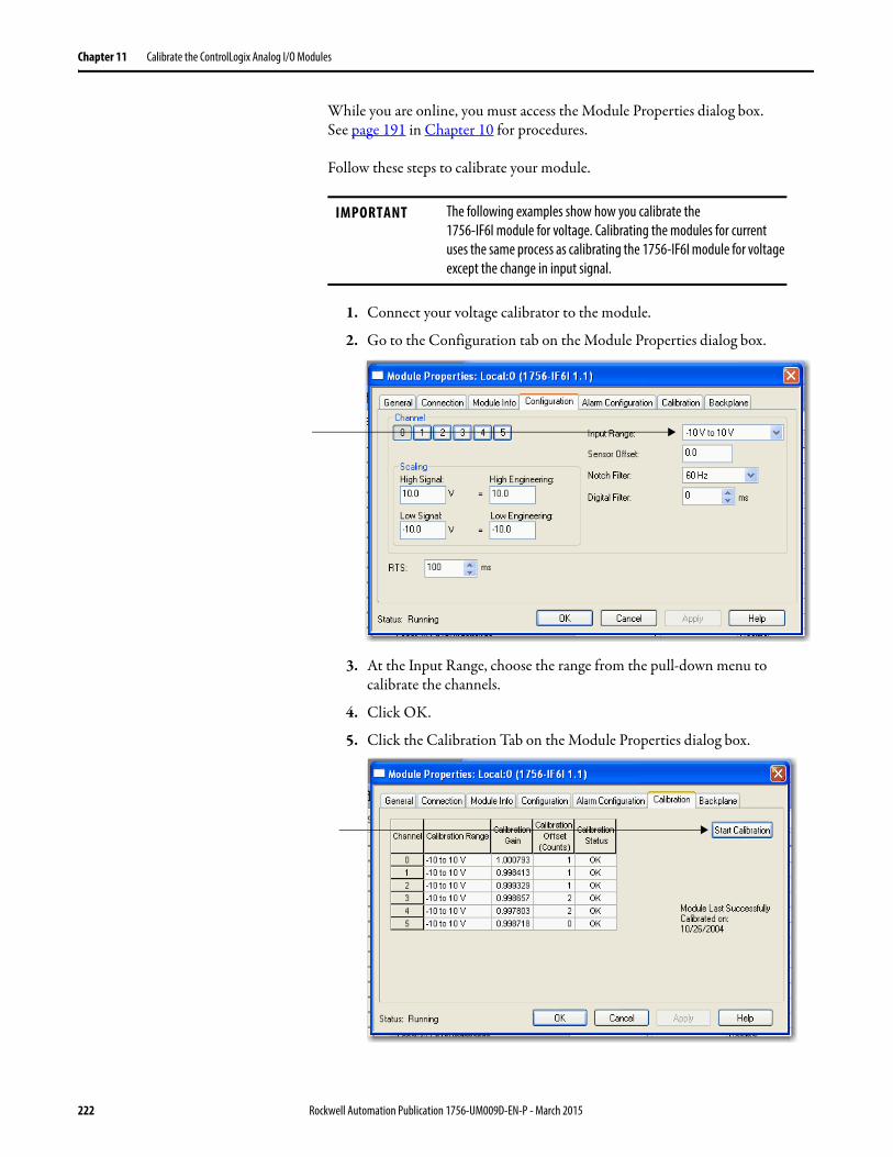
Chapter 11 Calibrate the ControlLogix Analog I/O Modules
While you are online, you must access the Module Properties dialog box.See page 191 in Chapter 10 for procedures.
Follow these steps to calibrate your module.
1. Connect your voltage calibrator to the module.
2. Go to the Configuration tab on the Module Properties dialog box.
3. At the Input Range, choose the range from the pull-down menu to calibrate the channels.
4. Click OK.
5. Click the Calibration Tab on the Module Properties dialog box.
IMPORTANT The following examples show how you calibrate the1756-IF6I module for voltage. Calibrating the modules for current uses the same process as calibrating the 1756-IF6I module for voltage except the change in input signal.
222 Rockwell Automation Publication 1756-UM009D-EN-P - March 2015
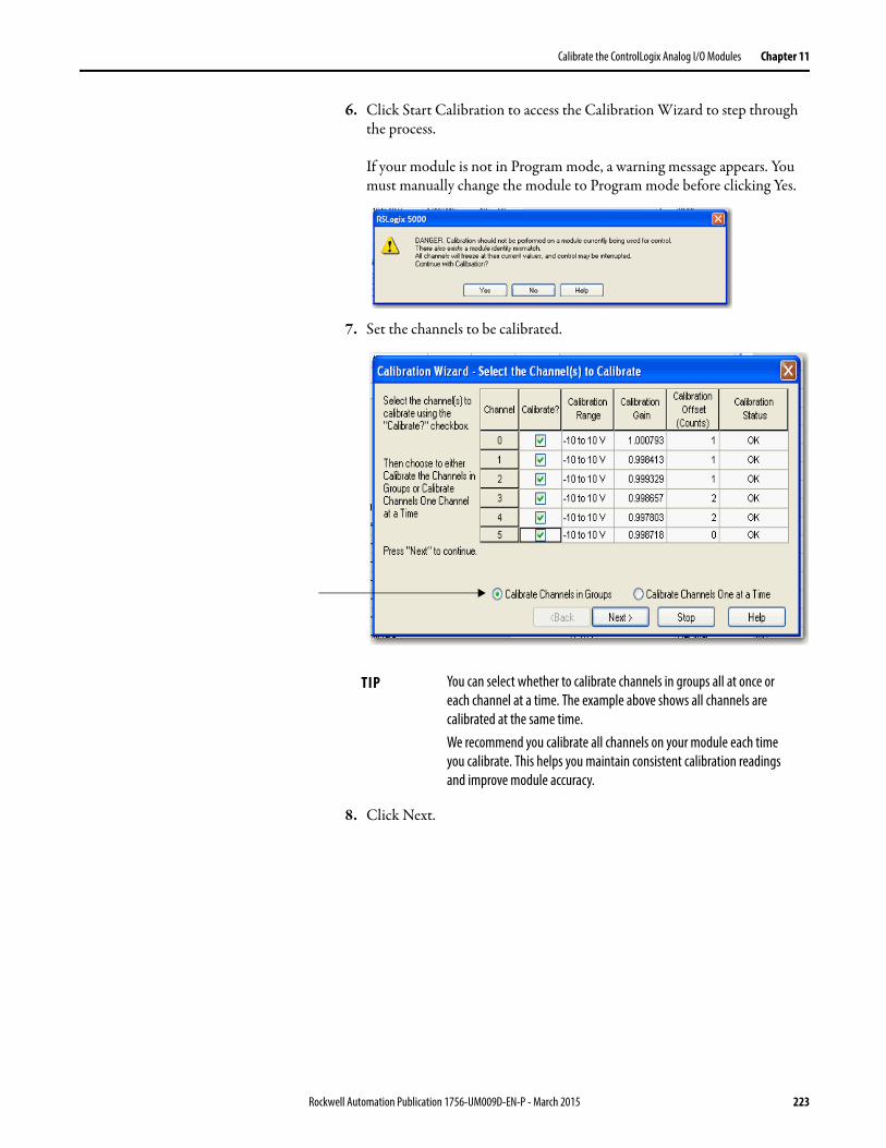
Calibrate the ControlLogix Analog I/O Modules Chapter 11
6. Click Start Calibration to access the Calibration Wizard to step through the process.
If your module is not in Program mode, a warning message appears. You must manually change the module to Program mode before clicking Yes.
7. Set the channels to be calibrated.
8. Click Next.
TIP You can select whether to calibrate channels in groups all at once or each channel at a time. The example above shows all channels are calibrated at the same time.We recommend you calibrate all channels on your module each time you calibrate. This helps you maintain consistent calibration readings and improve module accuracy.
Rockwell Automation Publication 1756-UM009D-EN-P - March 2015 223
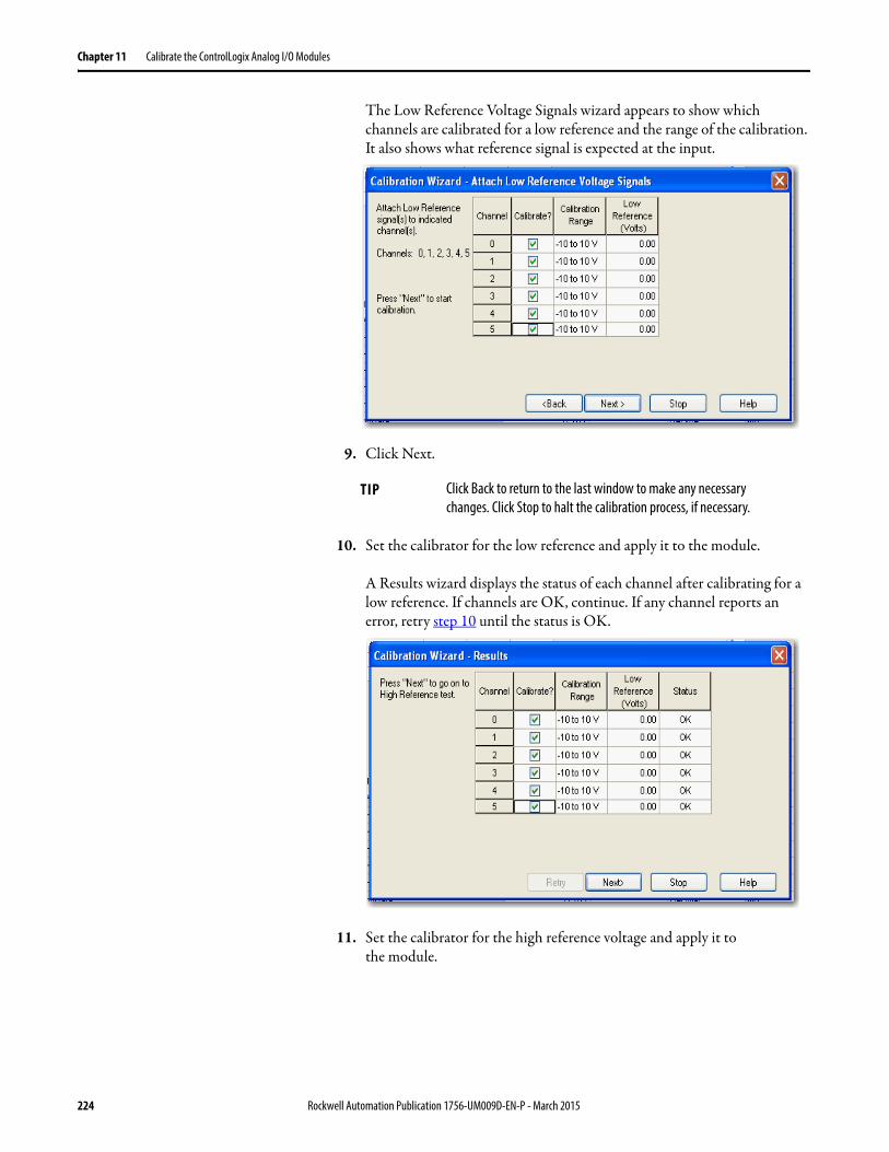
Chapter 11 Calibrate the ControlLogix Analog I/O Modules
The Low Reference Voltage Signals wizard appears to show which channels are calibrated for a low reference and the range of the calibration. It also shows what reference signal is expected at the input.
9. Click Next.
10. Set the calibrator for the low reference and apply it to the module.
A Results wizard displays the status of each channel after calibrating for a low reference. If channels are OK, continue. If any channel reports an error, retry step 10 until the status is OK.
11. Set the calibrator for the high reference voltage and apply it tothe module.
TIP Click Back to return to the last window to make any necessary changes. Click Stop to halt the calibration process, if necessary.
224 Rockwell Automation Publication 1756-UM009D-EN-P - March 2015
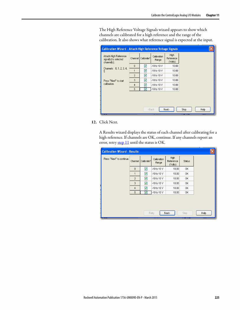
Calibrate the ControlLogix Analog I/O Modules Chapter 11
The High Reference Voltage Signals wizard appears to show which channels are calibrated for a high reference and the range of the calibration. It also shows what reference signal is expected at the input.
12. Click Next.
A Results wizard displays the status of each channel after calibrating for a high reference. If channels are OK, continue. If any channels report an error, retry step 11 until the status is OK.
Rockwell Automation Publication 1756-UM009D-EN-P - March 2015 225
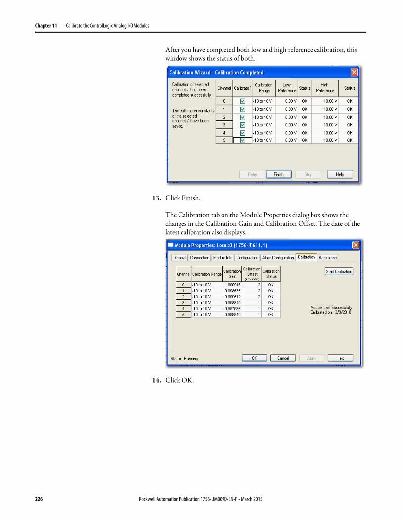
Chapter 11 Calibrate the ControlLogix Analog I/O Modules
After you have completed both low and high reference calibration, this window shows the status of both.
13. Click Finish.
The Calibration tab on the Module Properties dialog box shows the changes in the Calibration Gain and Calibration Offset. The date of the latest calibration also displays.
14. Click OK.
226 Rockwell Automation Publication 1756-UM009D-EN-P - March 2015
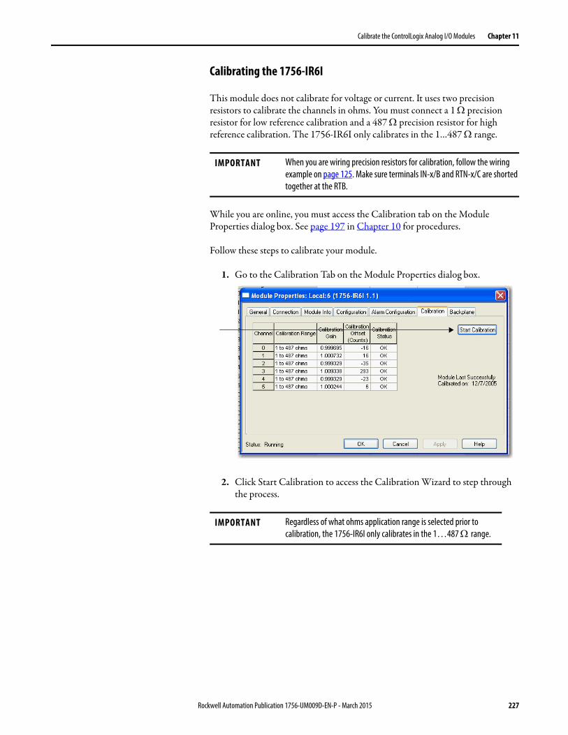
Calibrate the ControlLogix Analog I/O Modules Chapter 11
Calibrating the 1756-IR6I
This module does not calibrate for voltage or current. It uses two precision resistors to calibrate the channels in ohms. You must connect a 1 precision resistor for low reference calibration and a 487 precision resistor for high reference calibration. The 1756-IR6I only calibrates in the 1…487 range.
While you are online, you must access the Calibration tab on the Module Properties dialog box. See page 197 in Chapter 10 for procedures.
Follow these steps to calibrate your module.
1. Go to the Calibration Tab on the Module Properties dialog box.
2. Click Start Calibration to access the Calibration Wizard to step through the process.
IMPORTANT When you are wiring precision resistors for calibration, follow the wiring example on page 125. Make sure terminals IN-x/B and RTN-x/C are shorted together at the RTB.
IMPORTANT Regardless of what ohms application range is selected prior to calibration, the 1756-IR6I only calibrates in the 1…487 range.
Rockwell Automation Publication 1756-UM009D-EN-P - March 2015 227
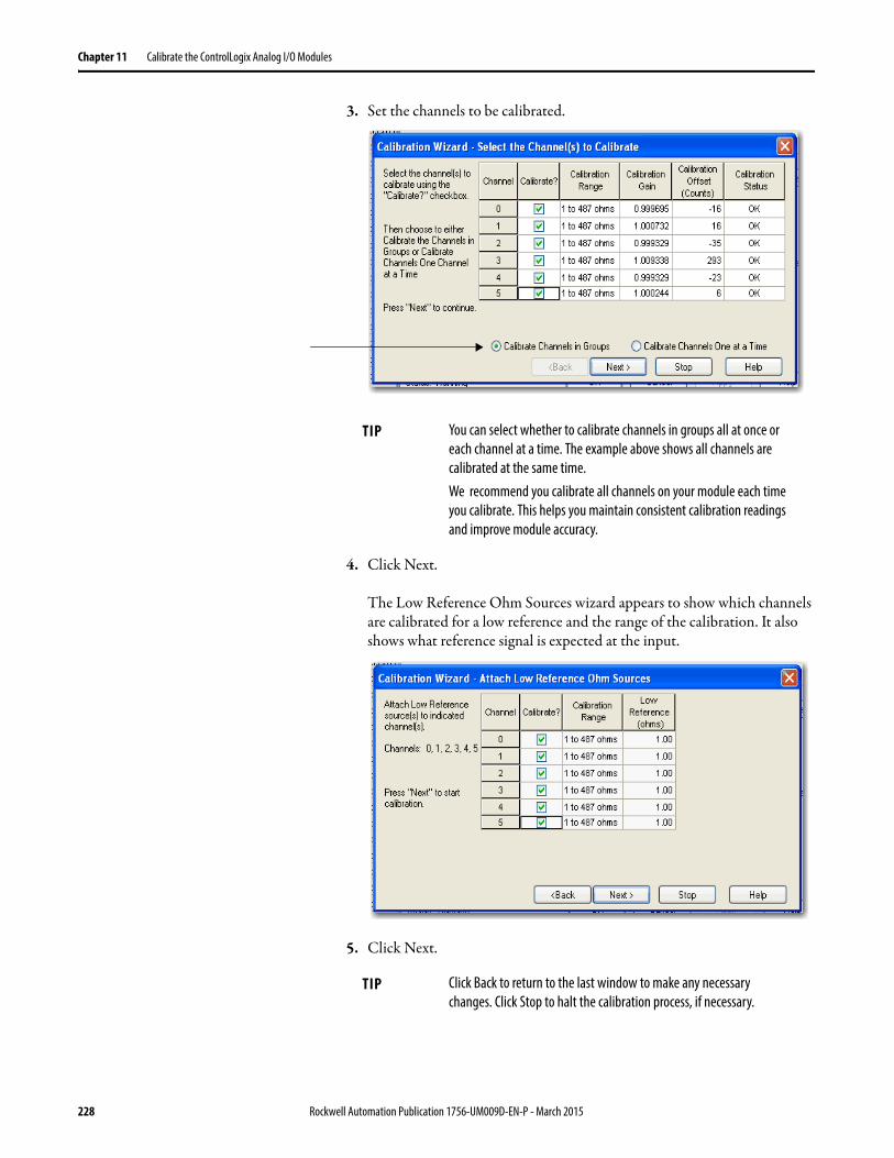
Chapter 11 Calibrate the ControlLogix Analog I/O Modules
3. Set the channels to be calibrated.
4. Click Next.
The Low Reference Ohm Sources wizard appears to show which channels are calibrated for a low reference and the range of the calibration. It also shows what reference signal is expected at the input.
5. Click Next.
TIP You can select whether to calibrate channels in groups all at once or each channel at a time. The example above shows all channels are calibrated at the same time.We recommend you calibrate all channels on your module each time you calibrate. This helps you maintain consistent calibration readings and improve module accuracy.
TIP Click Back to return to the last window to make any necessary changes. Click Stop to halt the calibration process, if necessary.
228 Rockwell Automation Publication 1756-UM009D-EN-P - March 2015
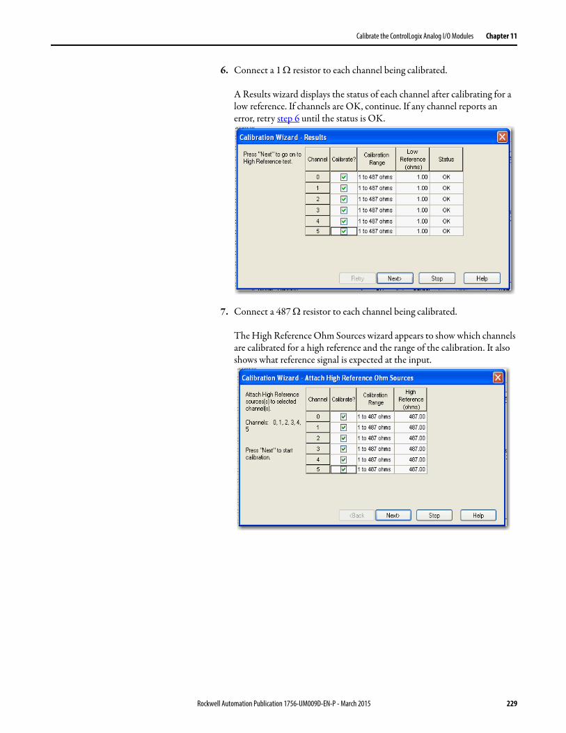
Calibrate the ControlLogix Analog I/O Modules Chapter 11
6. Connect a 1 resistor to each channel being calibrated.
A Results wizard displays the status of each channel after calibrating for a low reference. If channels are OK, continue. If any channel reports an error, retry step 6 until the status is OK.
7. Connect a 487 resistor to each channel being calibrated.
The High Reference Ohm Sources wizard appears to show which channels are calibrated for a high reference and the range of the calibration. It also shows what reference signal is expected at the input.
Rockwell Automation Publication 1756-UM009D-EN-P - March 2015 229
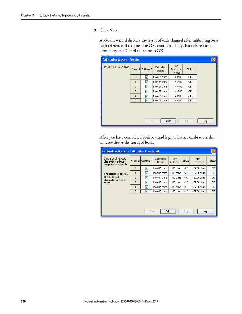
Chapter 11 Calibrate the ControlLogix Analog I/O Modules
8. Click Next.
A Results wizard displays the status of each channel after calibrating for a high reference. If channels are OK, continue. If any channels report an error, retry step 7 until the status is OK.
After you have completed both low and high reference calibration, this window shows the status of both.
230 Rockwell Automation Publication 1756-UM009D-EN-P - March 2015
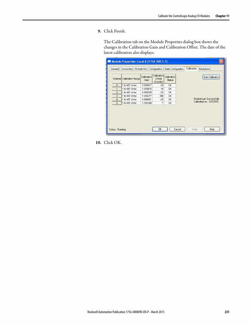
Calibrate the ControlLogix Analog I/O Modules Chapter 11
9. Click Finish.
The Calibration tab on the Module Properties dialog box shows the changes in the Calibration Gain and Calibration Offset. The date of the latest calibration also displays.
10. Click OK.
Rockwell Automation Publication 1756-UM009D-EN-P - March 2015 231
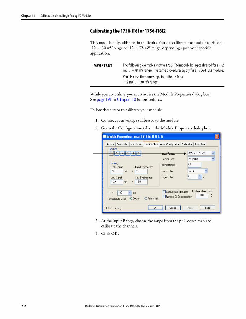
Chapter 11 Calibrate the ControlLogix Analog I/O Modules
Calibrating the 1756-IT6I or 1756-IT6I2
This module only calibrates in millivolts. You can calibrate the module to either a -12…+30 mV range or -12…+78 mV range, depending upon your specific application.
While you are online, you must access the Module Properties dialog box.See page 191 in Chapter 10 for procedures.
Follow these steps to calibrate your module.
1. Connect your voltage calibrator to the module.
2. Go to the Configuration tab on the Module Properties dialog box.
3. At the Input Range, choose the range from the pull-down menu to calibrate the channels.
4. Click OK.
IMPORTANT The following examples show a 1756-IT6I module being calibrated for a -12 mV…+78 mV range. The same procedures apply for a 1756-IT6I2 module.You also use the same steps to calibrate for a -12 mV…+30 mV range.
232 Rockwell Automation Publication 1756-UM009D-EN-P - March 2015
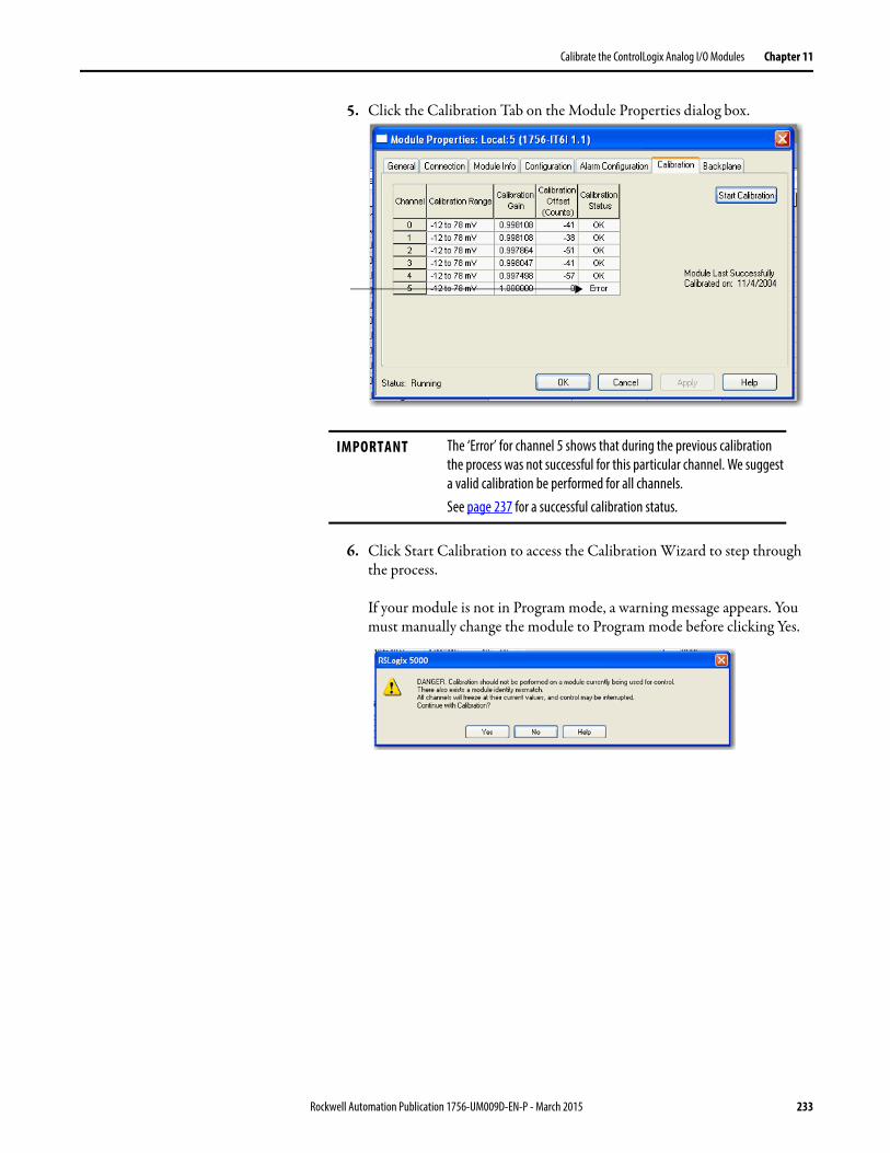
Calibrate the ControlLogix Analog I/O Modules Chapter 11
5. Click the Calibration Tab on the Module Properties dialog box.
6. Click Start Calibration to access the Calibration Wizard to step through the process.
If your module is not in Program mode, a warning message appears. You must manually change the module to Program mode before clicking Yes.
IMPORTANT The ‘Error’ for channel 5 shows that during the previous calibration the process was not successful for this particular channel. We suggest a valid calibration be performed for all channels.See page 237 for a successful calibration status.
Rockwell Automation Publication 1756-UM009D-EN-P - March 2015 233
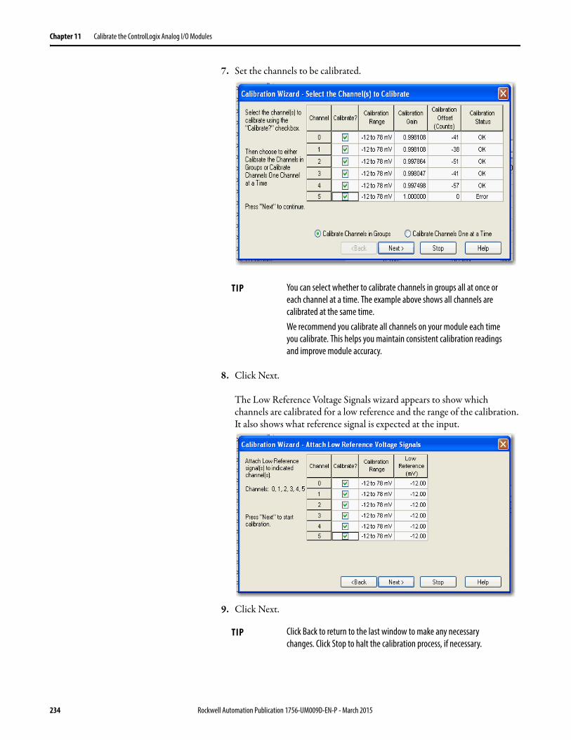
Chapter 11 Calibrate the ControlLogix Analog I/O Modules
7. Set the channels to be calibrated.
8. Click Next.
The Low Reference Voltage Signals wizard appears to show which channels are calibrated for a low reference and the range of the calibration. It also shows what reference signal is expected at the input.
9. Click Next.
TIP You can select whether to calibrate channels in groups all at once or each channel at a time. The example above shows all channels are calibrated at the same time.We recommend you calibrate all channels on your module each time you calibrate. This helps you maintain consistent calibration readings and improve module accuracy.
TIP Click Back to return to the last window to make any necessary changes. Click Stop to halt the calibration process, if necessary.
234 Rockwell Automation Publication 1756-UM009D-EN-P - March 2015
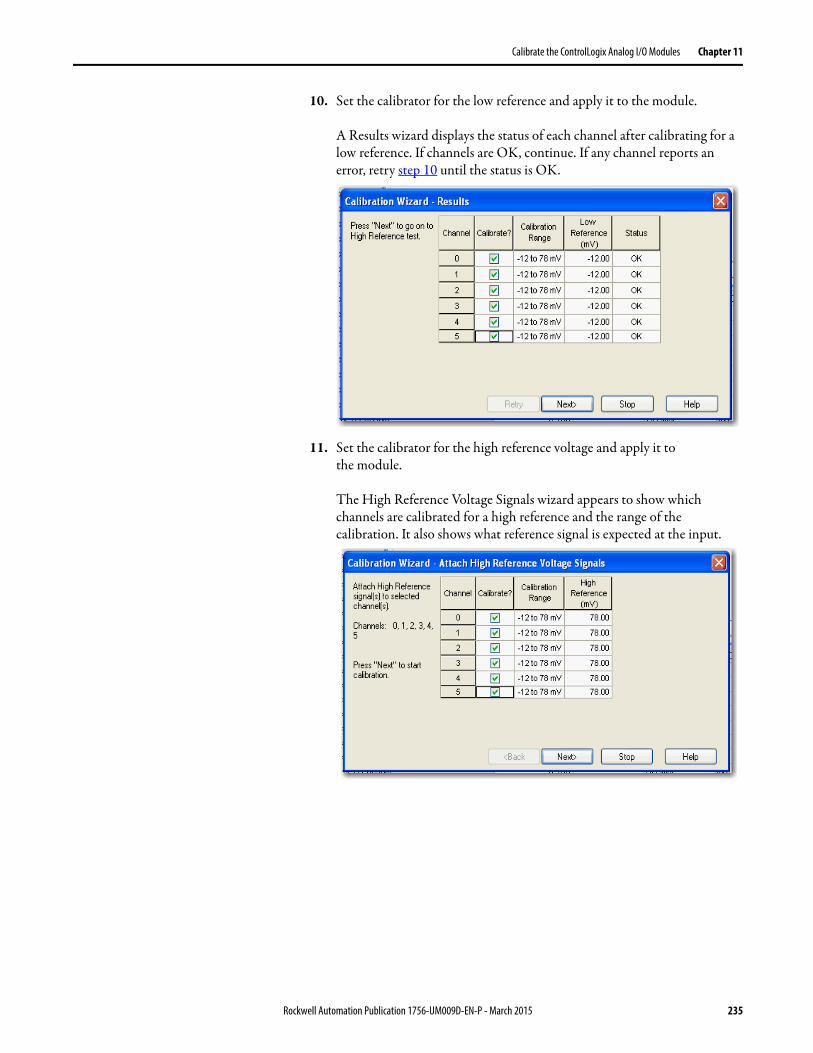
Calibrate the ControlLogix Analog I/O Modules Chapter 11
10. Set the calibrator for the low reference and apply it to the module.
A Results wizard displays the status of each channel after calibrating for a low reference. If channels are OK, continue. If any channel reports an error, retry step 10 until the status is OK.
11. Set the calibrator for the high reference voltage and apply it tothe module.
The High Reference Voltage Signals wizard appears to show which channels are calibrated for a high reference and the range of the calibration. It also shows what reference signal is expected at the input.
Rockwell Automation Publication 1756-UM009D-EN-P - March 2015 235

Chapter 11 Calibrate the ControlLogix Analog I/O Modules
12. Click Next.
A Results wizard displays the status of each channel after calibrating for a high reference. If channels are OK, continue. If any channels report an error, retry step 11 until the status is OK.
After you have completed both low and high reference calibration, this window shows the status of both.
236 Rockwell Automation Publication 1756-UM009D-EN-P - March 2015

Calibrate the ControlLogix Analog I/O Modules Chapter 11
13. Click Finish.
The Calibration tab on the Module Properties dialog box shows the changes in the Calibration Gain and Calibration Offset. The date of the latest calibration also displays.
14. Click OK.
Rockwell Automation Publication 1756-UM009D-EN-P - March 2015 237
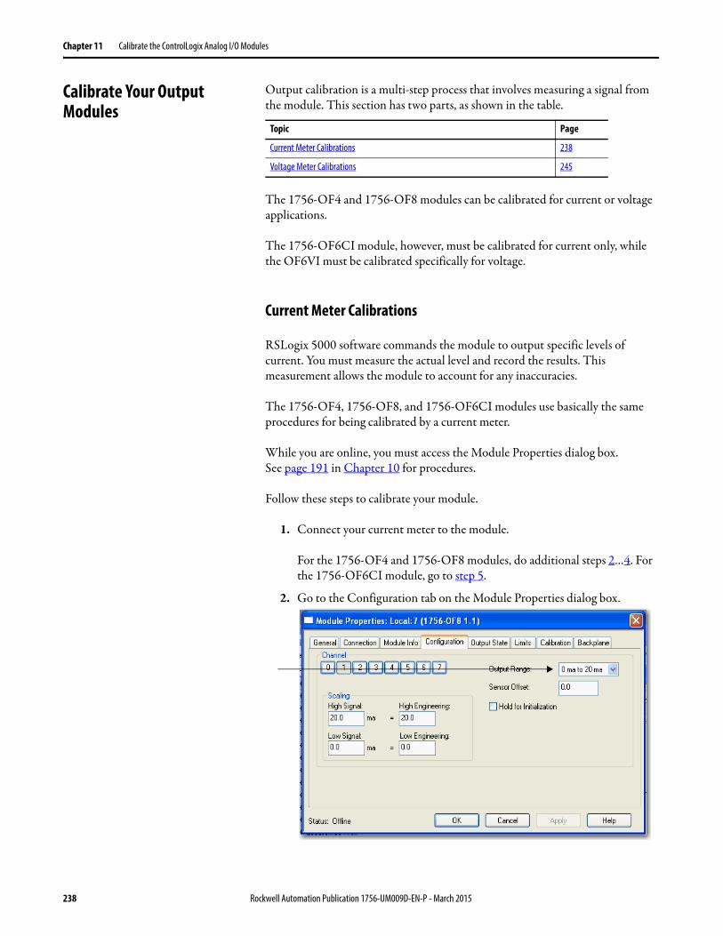
Chapter 11 Calibrate the ControlLogix Analog I/O Modules
Calibrate Your Output Modules
Output calibration is a multi-step process that involves measuring a signal from the module. This section has two parts, as shown in the table.
The 1756-OF4 and 1756-OF8 modules can be calibrated for current or voltage applications.
The 1756-OF6CI module, however, must be calibrated for current only, while the OF6VI must be calibrated specifically for voltage.
Current Meter Calibrations
RSLogix 5000 software commands the module to output specific levels of current. You must measure the actual level and record the results. This measurement allows the module to account for any inaccuracies.
The 1756-OF4, 1756-OF8, and 1756-OF6CI modules use basically the same procedures for being calibrated by a current meter.
While you are online, you must access the Module Properties dialog box.See page 191 in Chapter 10 for procedures.
Follow these steps to calibrate your module.
1. Connect your current meter to the module.
For the 1756-OF4 and 1756-OF8 modules, do additional steps 2…4. For the 1756-OF6CI module, go to step 5.
2. Go to the Configuration tab on the Module Properties dialog box.
Topic Page
Current Meter Calibrations 238
Voltage Meter Calibrations 245
238 Rockwell Automation Publication 1756-UM009D-EN-P - March 2015
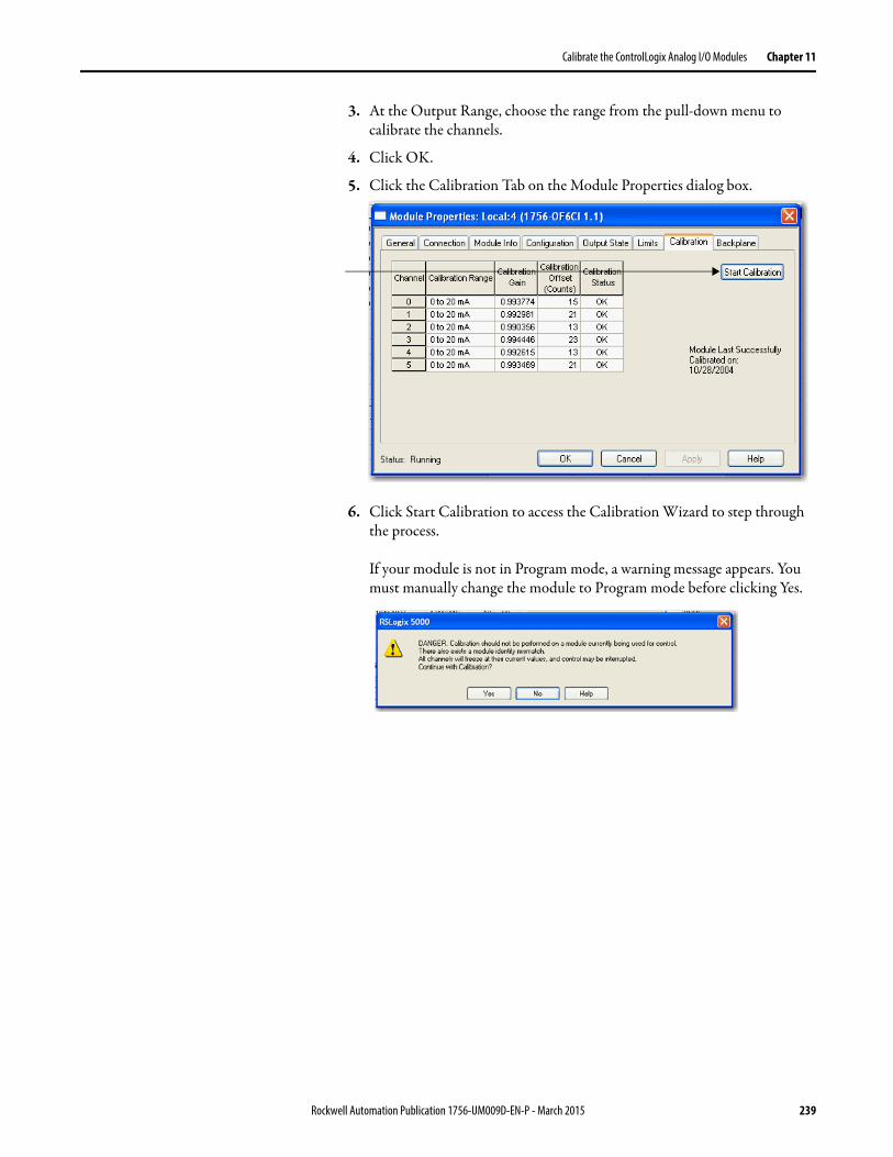
Calibrate the ControlLogix Analog I/O Modules Chapter 11
3. At the Output Range, choose the range from the pull-down menu to calibrate the channels.
4. Click OK.
5. Click the Calibration Tab on the Module Properties dialog box.
6. Click Start Calibration to access the Calibration Wizard to step through the process.
If your module is not in Program mode, a warning message appears. You must manually change the module to Program mode before clicking Yes.
Rockwell Automation Publication 1756-UM009D-EN-P - March 2015 239
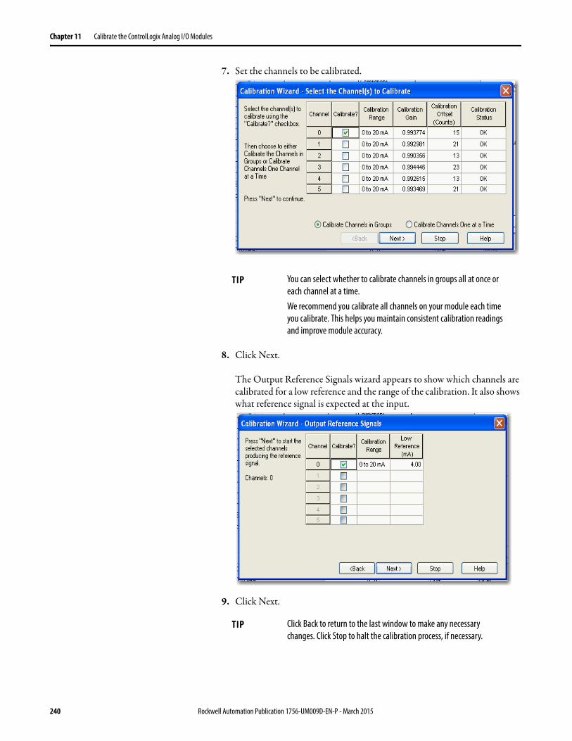
Chapter 11 Calibrate the ControlLogix Analog I/O Modules
7. Set the channels to be calibrated.
8. Click Next.
The Output Reference Signals wizard appears to show which channels are calibrated for a low reference and the range of the calibration. It also shows what reference signal is expected at the input.
9. Click Next.
TIP You can select whether to calibrate channels in groups all at once or each channel at a time.We recommend you calibrate all channels on your module each time you calibrate. This helps you maintain consistent calibration readings and improve module accuracy.
TIP Click Back to return to the last window to make any necessary changes. Click Stop to halt the calibration process, if necessary.
240 Rockwell Automation Publication 1756-UM009D-EN-P - March 2015
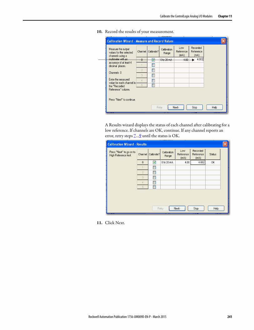
Calibrate the ControlLogix Analog I/O Modules Chapter 11
10. Record the results of your measurement.
A Results wizard displays the status of each channel after calibrating for a low reference. If channels are OK, continue. If any channel reports an error, retry steps 7…9 until the status is OK.
11. Click Next.
Rockwell Automation Publication 1756-UM009D-EN-P - March 2015 241
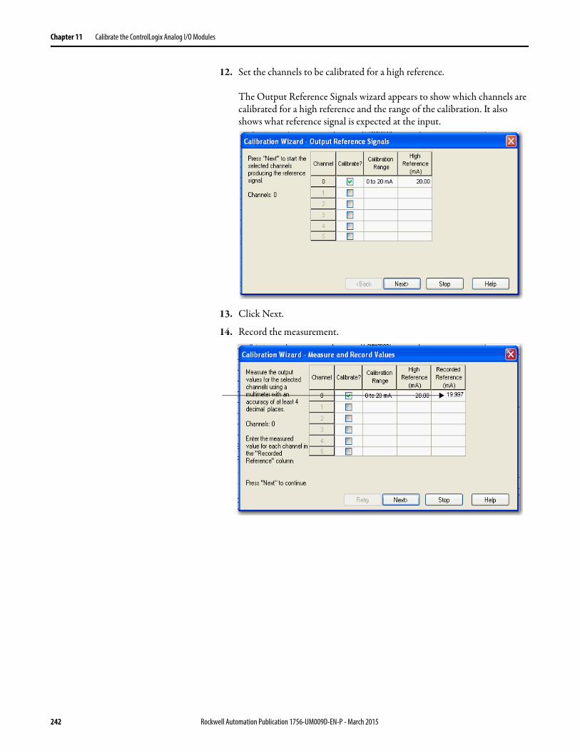
Chapter 11 Calibrate the ControlLogix Analog I/O Modules
12. Set the channels to be calibrated for a high reference.
The Output Reference Signals wizard appears to show which channels are calibrated for a high reference and the range of the calibration. It also shows what reference signal is expected at the input.
13. Click Next.
14. Record the measurement.
242 Rockwell Automation Publication 1756-UM009D-EN-P - March 2015

Calibrate the ControlLogix Analog I/O Modules Chapter 11
15. Click Next.
A Results wizard displays the status of each channel after calibrating for a high reference. If channels are OK, continue. If any channels report an error, retry steps 12…15 until the status is OK.
After you have completed both low and high reference calibration, this window shows the status of both.
Rockwell Automation Publication 1756-UM009D-EN-P - March 2015 243
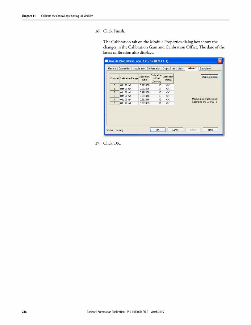
Chapter 11 Calibrate the ControlLogix Analog I/O Modules
16. Click Finish.
The Calibration tab on the Module Properties dialog box shows the changes in the Calibration Gain and Calibration Offset. The date of the latest calibration also displays.
17. Click OK.
244 Rockwell Automation Publication 1756-UM009D-EN-P - March 2015
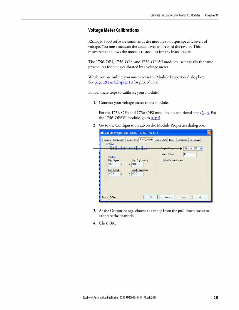
Calibrate the ControlLogix Analog I/O Modules Chapter 11
Voltage Meter Calibrations
RSLogix 5000 software commands the module to output specific levels of voltage. You must measure the actual level and record the results. This measurement allows the module to account for any inaccuracies.
The 1756-OF4, 1756-OF8, and 1756-OF6VI modules use basically the same procedures for being calibrated by a voltage meter.
While you are online, you must access the Module Properties dialog box.See page 191 in Chapter 10 for procedures.
Follow these steps to calibrate your module.
1. Connect your voltage meter to the module.
For the 1756-OF4 and 1756-OF8 modules, do additional steps 2…4. For the 1756-OF6VI module, go to step 5.
2. Go to the Configuration tab on the Module Properties dialog box.
3. At the Output Range, choose the range from the pull-down menu to calibrate the channels.
4. Click OK.
Rockwell Automation Publication 1756-UM009D-EN-P - March 2015 245
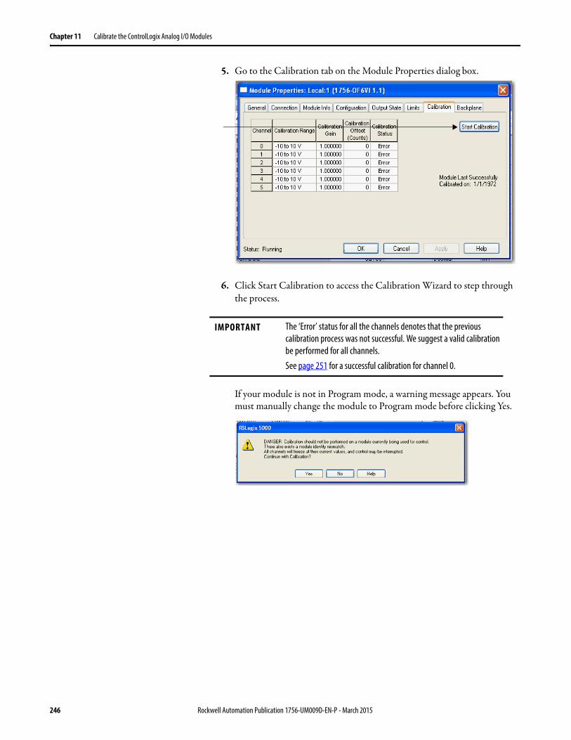
Chapter 11 Calibrate the ControlLogix Analog I/O Modules
5. Go to the Calibration tab on the Module Properties dialog box.
6. Click Start Calibration to access the Calibration Wizard to step through the process.
If your module is not in Program mode, a warning message appears. You must manually change the module to Program mode before clicking Yes.
IMPORTANT The ‘Error’ status for all the channels denotes that the previous calibration process was not successful. We suggest a valid calibration be performed for all channels.See page 251 for a successful calibration for channel 0.
246 Rockwell Automation Publication 1756-UM009D-EN-P - March 2015
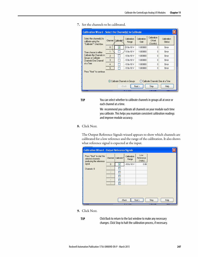
Calibrate the ControlLogix Analog I/O Modules Chapter 11
7. Set the channels to be calibrated.
8. Click Next.
The Output Reference Signals wizard appears to show which channels are calibrated for a low reference and the range of the calibration. It also shows what reference signal is expected at the input.
9. Click Next.
TIP You can select whether to calibrate channels in groups all at once or each channel at a time.We recommend you calibrate all channels on your module each time you calibrate. This helps you maintain consistent calibration readings and improve module accuracy.
TIP Click Back to return to the last window to make any necessary changes. Click Stop to halt the calibration process, if necessary.
Rockwell Automation Publication 1756-UM009D-EN-P - March 2015 247
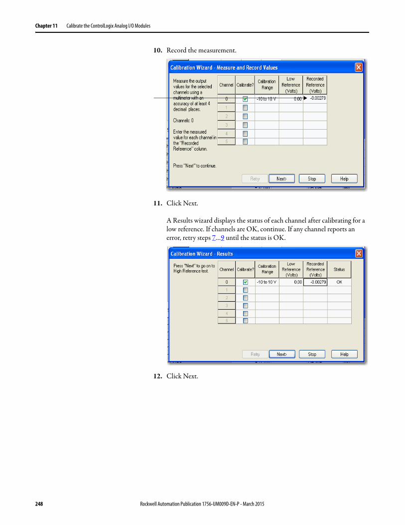
Chapter 11 Calibrate the ControlLogix Analog I/O Modules
10. Record the measurement.
11. Click Next.
A Results wizard displays the status of each channel after calibrating for a low reference. If channels are OK, continue. If any channel reports an error, retry steps 7…9 until the status is OK.
12. Click Next.
248 Rockwell Automation Publication 1756-UM009D-EN-P - March 2015
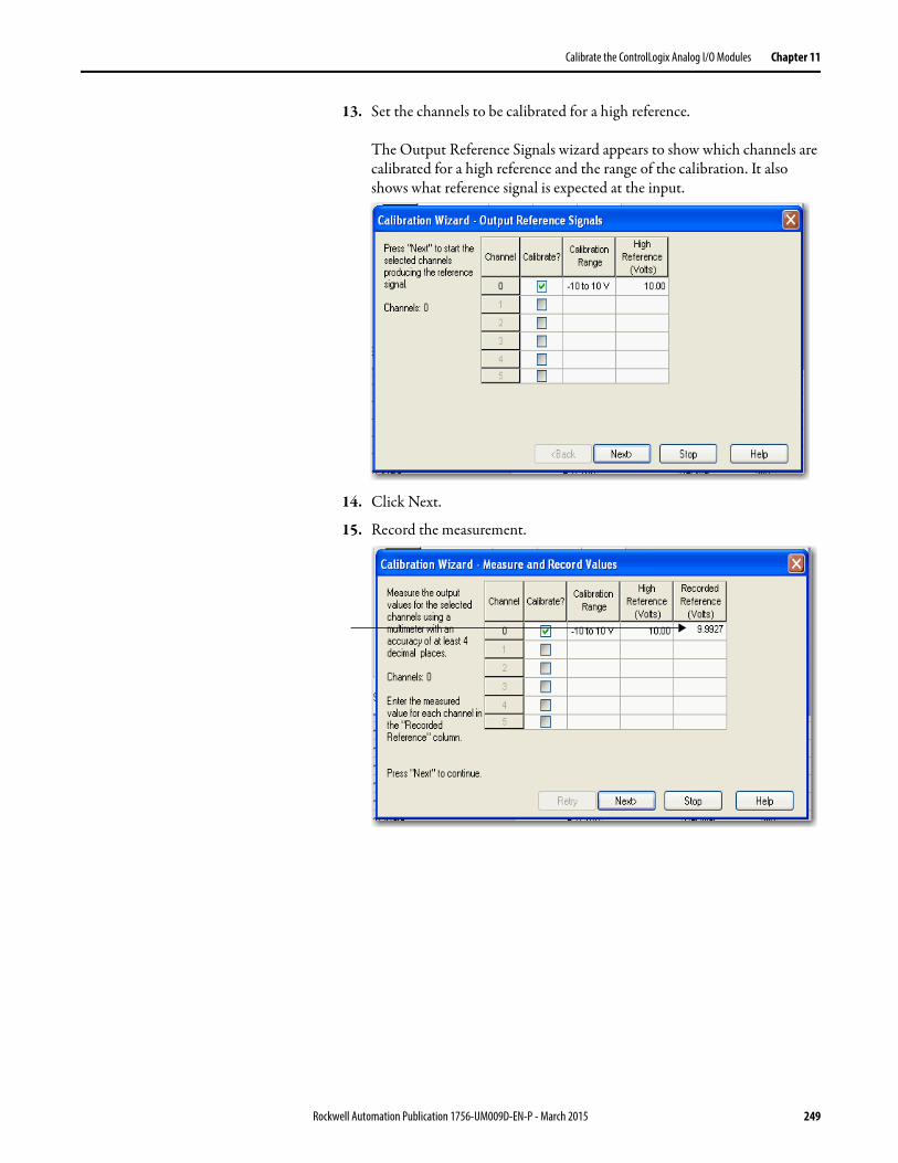
Calibrate the ControlLogix Analog I/O Modules Chapter 11
13. Set the channels to be calibrated for a high reference.
The Output Reference Signals wizard appears to show which channels are calibrated for a high reference and the range of the calibration. It also shows what reference signal is expected at the input.
14. Click Next.
15. Record the measurement.
Rockwell Automation Publication 1756-UM009D-EN-P - March 2015 249
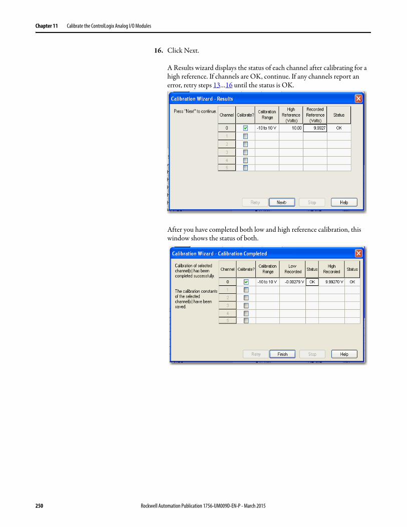
Chapter 11 Calibrate the ControlLogix Analog I/O Modules
16. Click Next.
A Results wizard displays the status of each channel after calibrating for a high reference. If channels are OK, continue. If any channels report an error, retry steps 13…16 until the status is OK.
After you have completed both low and high reference calibration, this window shows the status of both.
250 Rockwell Automation Publication 1756-UM009D-EN-P - March 2015
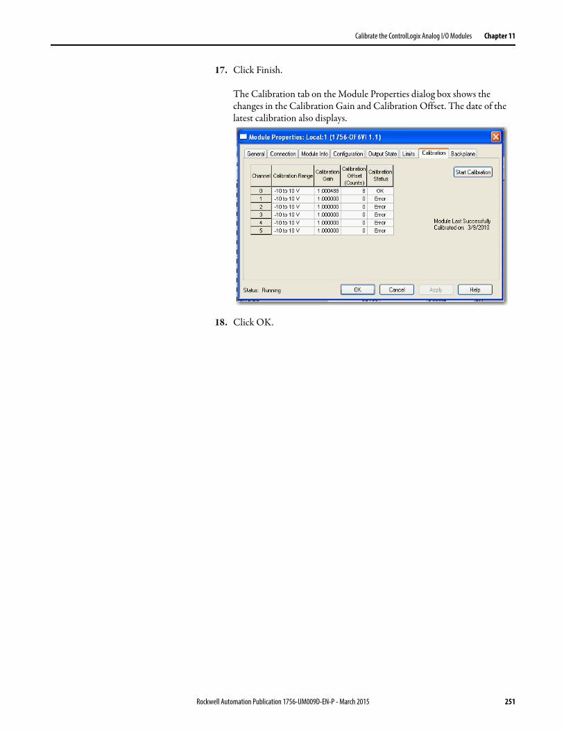
Calibrate the ControlLogix Analog I/O Modules Chapter 11
17. Click Finish.
The Calibration tab on the Module Properties dialog box shows the changes in the Calibration Gain and Calibration Offset. The date of the latest calibration also displays.
18. Click OK.
Rockwell Automation Publication 1756-UM009D-EN-P - March 2015 251

Chapter 11 Calibrate the ControlLogix Analog I/O Modules
Notes:
252 Rockwell Automation Publication 1756-UM009D-EN-P - March 2015
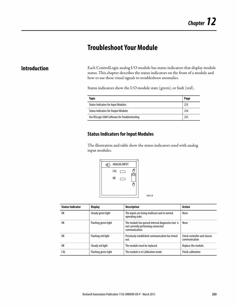
Chapter 12
Troubleshoot Your Module
Introduction Each ControlLogix analog I/O module has status indicators that display module status. This chapter describes the status indicators on the front of a module and how to use these visual signals to troubleshoot anomalies.
Status indicators show the I/O module state (green), or fault (red).
Status Indicators for Input Modules
The illustration and table show the status indicators used with analoginput modules.
Topic Page
Status Indicators for Input Modules 253
Status Indicators for Output Modules 254
Use RSLogix 5000 Software for Troubleshooting 255
Status Indicator Display Description Action
OK Steady green light The inputs are being multicast and in normal operating state.
None
OK Flashing green light The module has passed internal diagnostics but is not currently performing connected communication.
None
OK Flashing red light Previously established communication has timed out.
Check controller and chassis communication
OK Steady red light The module must be replaced. Replace the module.
CAL Flashing green light The module is in Calibration mode. Finish calibration
20962-M
ANALOG INPUT
CAL
OK
Rockwell Automation Publication 1756-UM009D-EN-P - March 2015 253
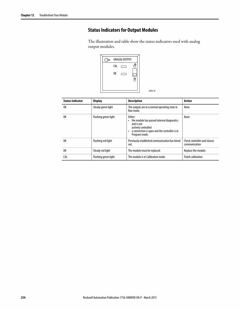
Chapter 12 Troubleshoot Your Module
Status Indicators for Output Modules
The illustration and table show the status indicators used with analogoutput modules.
Status Indicator Display Description Action
OK Steady green light The outputs are in a normal operating state in Run mode.
None
OK Flashing green light Either:• the module has passed internal diagnostics
and is notactively controlled
• a connection is open and the controller is in Program mode.
None
OK Flashing red light Previously established communication has timed out.
Check controller and chassis communication
OK Steady red light The module must be replaced. Replace the module.
CAL Flashing green light The module is in Calibration mode. Finish calibration
20965-M
ANALOG OUTPUT
CAL
OK
254 Rockwell Automation Publication 1756-UM009D-EN-P - March 2015
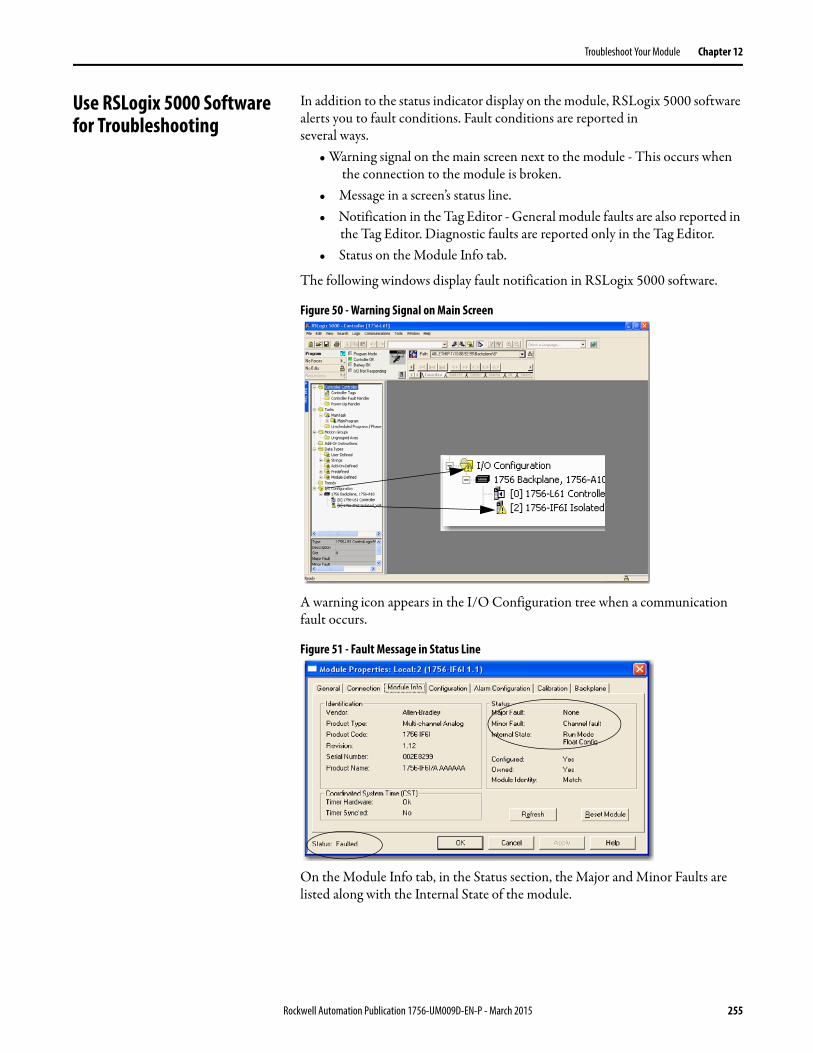
Troubleshoot Your Module Chapter 12
Use RSLogix 5000 Software for Troubleshooting
In addition to the status indicator display on the module, RSLogix 5000 software alerts you to fault conditions. Fault conditions are reported inseveral ways.
• Warning signal on the main screen next to the module - This occurs when the connection to the module is broken.
• Message in a screen’s status line.• Notification in the Tag Editor - General module faults are also reported in
the Tag Editor. Diagnostic faults are reported only in the Tag Editor.• Status on the Module Info tab.
The following windows display fault notification in RSLogix 5000 software.
Figure 50 - Warning Signal on Main Screen
A warning icon appears in the I/O Configuration tree when a communication fault occurs.
Figure 51 - Fault Message in Status Line
On the Module Info tab, in the Status section, the Major and Minor Faults are listed along with the Internal State of the module.
Rockwell Automation Publication 1756-UM009D-EN-P - March 2015 255

Chapter 12 Troubleshoot Your Module
Figure 52 - Notification in Tag Editor
The Value field lists the number 1 in the Fault line.
Fault Type Determination
When you are monitoring a module’s configuration properties inRSLogix 5000 software and receive a Communication fault message, the Connection tab lists the type of fault under Module Fault.
256 Rockwell Automation Publication 1756-UM009D-EN-P - March 2015
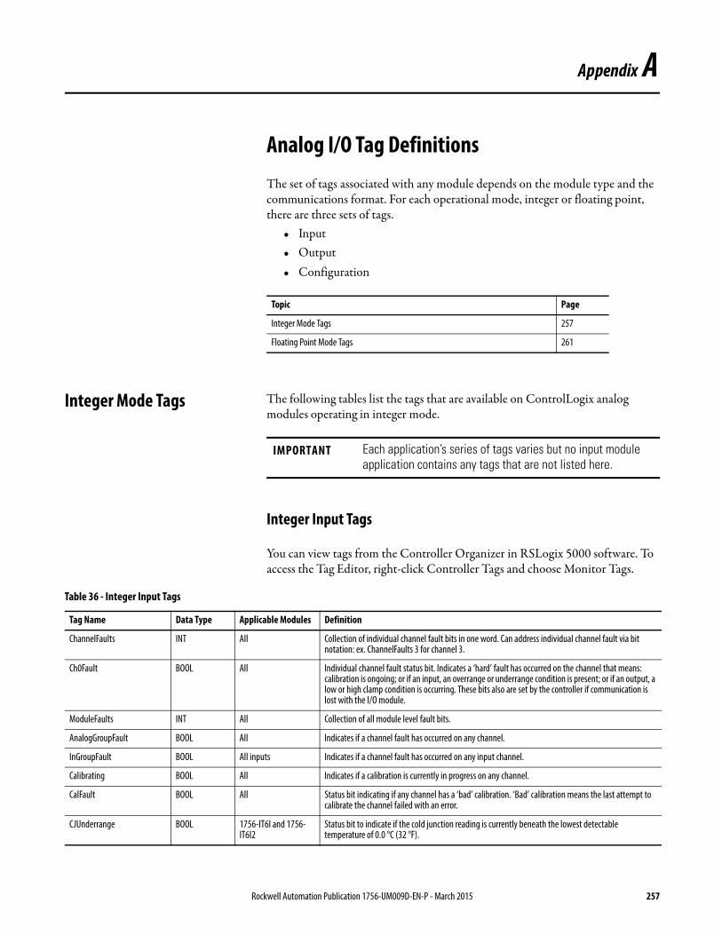
Appendix A
Analog I/O Tag DefinitionsThe set of tags associated with any module depends on the module type and the communications format. For each operational mode, integer or floating point, there are three sets of tags.
• Input• Output• Configuration
Integer Mode Tags The following tables list the tags that are available on ControlLogix analog modules operating in integer mode.
Integer Input Tags
You can view tags from the Controller Organizer in RSLogix 5000 software. To access the Tag Editor, right-click Controller Tags and choose Monitor Tags.
Topic Page
Integer Mode Tags 257
Floating Point Mode Tags 261
IMPORTANT Each application’s series of tags varies but no input module application contains any tags that are not listed here.
Table 36 - Integer Input Tags
Tag Name Data Type Applicable Modules Definition
ChannelFaults INT All Collection of individual channel fault bits in one word. Can address individual channel fault via bit notation: ex. ChannelFaults 3 for channel 3.
Ch0Fault BOOL All Individual channel fault status bit. Indicates a ‘hard’ fault has occurred on the channel that means: calibration is ongoing; or if an input, an overrange or underrange condition is present; or if an output, a low or high clamp condition is occurring. These bits also are set by the controller if communication is lost with the I/O module.
ModuleFaults INT All Collection of all module level fault bits.
AnalogGroupFault BOOL All Indicates if a channel fault has occurred on any channel.
InGroupFault BOOL All inputs Indicates if a channel fault has occurred on any input channel.
Calibrating BOOL All Indicates if a calibration is currently in progress on any channel.
CalFault BOOL All Status bit indicating if any channel has a ‘bad’ calibration. ‘Bad’ calibration means the last attempt to calibrate the channel failed with an error.
CJUnderrange BOOL 1756-IT6I and 1756-IT6I2
Status bit to indicate if the cold junction reading is currently beneath the lowest detectable temperature of 0.0 °C (32 °F).
Rockwell Automation Publication 1756-UM009D-EN-P - March 2015 257
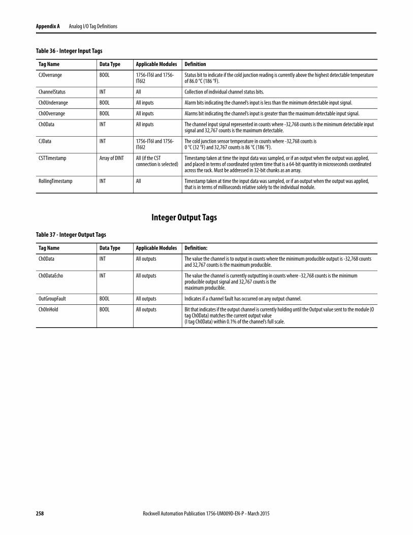
Appendix A Analog I/O Tag Definitions
Integer Output Tags
CJOverrange BOOL 1756-IT6I and 1756-IT6I2
Status bit to indicate if the cold junction reading is currently above the highest detectable temperature of 86.0 °C (186 °F).
ChannelStatus INT All Collection of individual channel status bits.
Ch0Underrange BOOL All inputs Alarm bits indicating the channel’s input is less than the minimum detectable input signal.
Ch0Overrange BOOL All inputs Alarms bit indicating the channel’s input is greater than the maximum detectable input signal.
Ch0Data INT All inputs The channel input signal represented in counts where -32,768 counts is the minimum detectable input signal and 32,767 counts is the maximum detectable.
CJData INT 1756-IT6I and 1756-IT6I2
The cold junction sensor temperature in counts where -32,768 counts is0 °C (32 °F) and 32,767 counts is 86 °C (186 °F).
CSTTimestamp Array of DINT All (if the CST connection is selected)
Timestamp taken at time the input data was sampled, or if an output when the output was applied, and placed in terms of coordinated system time that is a 64-bit quantity in microseconds coordinated across the rack. Must be addressed in 32-bit chunks as an array.
RollingTimestamp INT All Timestamp taken at time the input data was sampled, or if an output when the output was applied, that is in terms of milliseconds relative solely to the individual module.
Table 36 - Integer Input Tags
Tag Name Data Type Applicable Modules Definition
Table 37 - Integer Output Tags
Tag Name Data Type Applicable Modules Definition:
Ch0Data INT All outputs The value the channel is to output in counts where the minimum producible output is -32,768 counts and 32,767 counts is the maximum producible.
Ch0DataEcho INT All outputs The value the channel is currently outputting in counts where -32,768 counts is the minimum producible output signal and 32,767 counts is themaximum producible.
OutGroupFault BOOL All outputs Indicates if a channel fault has occurred on any output channel.
Ch0InHold BOOL All outputs Bit that indicates if the output channel is currently holding until the Output value sent to the module (O tag Ch0Data) matches the current output value(I tag Ch0Data) within 0.1% of the channel’s full scale.
258 Rockwell Automation Publication 1756-UM009D-EN-P - March 2015
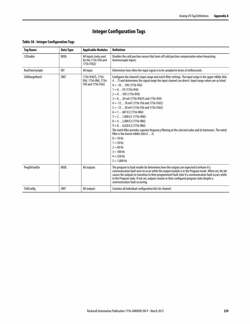
Analog I/O Tag Definitions Appendix A
Integer Configuration Tags
Table 38 - Integer Configuration Tags
Tag Name Data Type Applicable Modules Definition
CJDisable BOOL All inputs (only used for the 1756-IT6I and 1756-IT6I2)
Disables the cold junction sensor that turns off cold junction compensation when linearizing thermocouple inputs.
RealTimeSample INT All input Determines how often the input signal is to be sampled in terms of milliseconds.
Ch0RangeNotch SINT 1756-IF6CIS, 1756-IF6I, 1756-IR6I, 1756-IT6I and 1756-IT6I2
Configures the channel’s input range and notch filter settings. The input range is the upper nibble (bits 4…7) and determines the signal range the input channel can detect. Input range values are as listed.0 = -10…10V (1756-IF6I)1 = 0…5V (1756-IF6I)2 = 0…10V (1756-IF6I)3 = 0…20 mA (1756-IF6CIS and 1756-IF6I)4 = -12…78 mV (1756-IT6I and 1756-IT6I2)5 = -12…30 mV (1756-IT6I and 1756-IT6I2)6 = 1…487 (1756-IR6I)7 = 2…1,000 (1756-IR6I)8 = 4…2,000 (1756-IR6I)9 = 8…4,020 (1756-IR6I)The notch filter provides superior frequency filtering at the selected value and its harmonics. The notch filter is the lowest nibble (bits 0…3).0 = 10 Hz1 = 50 Hz2 = 60 Hz3 = 100 Hz4 = 250 Hz5 = 1,000 Hz
ProgToFaultEn BOOL All outputs The program to fault enable bit determines how the outputs are expected to behave if a communication fault were to occur while the output module is in the Program mode. When set, the bit causes the outputs to transition to their programmed Fault state if a communication fault occurs while in the Program state. If not set, outputs remain in their configured program state despite a communication fault occurring.
Ch0Config SINT All outputs Contains all individual configuration bits for channel.
Rockwell Automation Publication 1756-UM009D-EN-P - March 2015 259
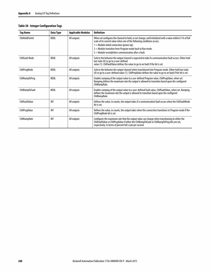
Appendix A Analog I/O Tag Definitions
Ch0HoldForInit BOOL All outputs When set configures the channel to hold, or not change, until initialized with a value within 0.1% of full scale of its current value when one of the following conditions occurs.1 = Module initial connection (power up).2 = Module transition from Program mode back to Run mode.3 = Module reestablishes communication after a fault.
Ch0Fault Mode BOOL All outputs Selects the behavior the output channel is expected to take if a communication fault occurs. Either hold last state (0) or go to a user-definedvalue (1). Ch0FaultValue defines the value to go to on fault if the bit is set.
Ch0ProgMode BOOL All outputs Selects the behavior the output channel when transitioned into Program mode. Either hold last state (0) or go to a user-defined value (1). Ch0ProgValue defines the value to go to on fault if the bit is set.
Ch0RampToProg BOOL All outputs Enables ramping of the output value to a use-defined Program value, Ch0ProgValue, when set. Ramping defines the maximum rate the output is allowed to transition based upon the configured Ch0RampRate.
Ch0RampToFault BOOL All outputs Enables ramping of the output value to a user-defined Fault value, Ch0FaultValue, when set. Ramping defines the maximum rate the output is allowed to transition based upon the configured Ch0RampRate.
Ch0FaultValue INT All outputs Defines the value, in counts, the output takes if a communication fault occurs when the Ch0FaultMode bit is set.
Ch0ProgValue INT All outputs Defines the value, in counts, the output takes when the connection transitions to Program mode if the Ch0ProgMode bit is set.
Ch0RampRate INT All outputs Configures the maximum rate that the output value can change when transitioning to either the Ch0FaultValue or Ch0ProgValue if either the Ch0RampToFault or Ch0RampToProg bits are set, respectively. In terms of percent full-scale per second.
Table 38 - Integer Configuration Tags
Tag Name Data Type Applicable Modules Definition
260 Rockwell Automation Publication 1756-UM009D-EN-P - March 2015
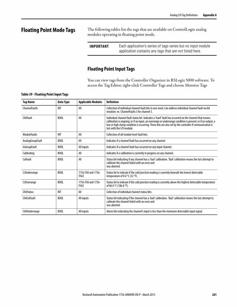
Analog I/O Tag Definitions Appendix A
Floating Point Mode Tags The following tables list the tags that are available on ControlLogix analog modules operating in floating point mode.
Floating Point Input Tags
You can view tags from the Controller Organizer in RSLogix 5000 software. To access the Tag Editor, right-click Controller Tags and choose Monitor Tags
IMPORTANT Each application’s series of tags varies but no input module application contains any tags that are not listed here.
Table 39 - Floating Point Input Tags
Tag Name Data Type Applicable Modules Definition
ChannelFaults INT All Collection of individual channel fault bits in one word. Can address individual channel fault via bit notation: ex. ChannelFaults 3 for channel 3.
Ch0Fault BOOL All Individual channel fault status bit. Indicates a ‘hard’ fault has occurred on the channel that means: calibration is ongoing; or if an input, an overrange or underrange condition is present; or if an output, a low or high clamp condition is occurring. These bits are also set by the controller if communication is lost with the I/O module.
ModuleFaults INT All Collection of all module level fault bits.
AnalogGroupFault BOOL All Indicates if a channel fault has occurred on any channel.
InGroupFault BOOL All inputs Indicates if a channel fault has occurred on any input channel.
Calibrating BOOL All Indicates if a calibration is currently in progress on any channel.
CalFault BOOL All Status bit indicating if any channel has a ‘bad’ calibration. ‘Bad’ calibration means the last attempt to calibrate the channel failed with an error andwas aborted.
CJUnderrange BOOL 1756-IT6I and 1756-IT6I2
Status bit to indicate if the cold junction reading is currently beneath the lowest detectable temperature of 0.0 °C (32 °F).
CJOverrange BOOL 1756-IT6I and 1756-IT6I2
Status bit to indicate if the cold junction reading is currently above the highest detectable temperature of 86.0 °C (186.8 °F).
Ch0Status INT All Collection of individual channel status bits.
Ch0CalFault BOOL All inputs Status bit indicating if the channel has a ‘bad’ calibration. ‘Bad’ calibration means the last attempt to calibrate the channel failed with an error andwas aborted.
Ch0Underrange BOOL All inputs Alarm bits indicating the channel’s input is less than the minimum detectable input signal.
Rockwell Automation Publication 1756-UM009D-EN-P - March 2015 261
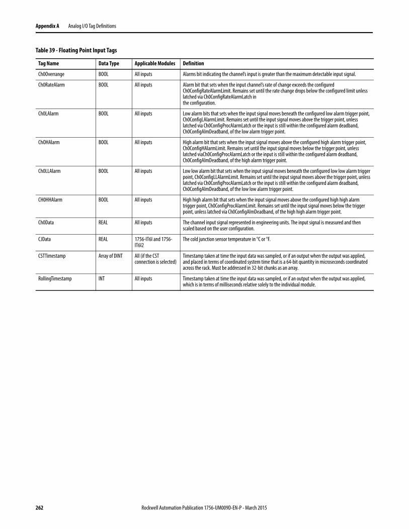
Appendix A Analog I/O Tag Definitions
Ch0Overrange BOOL All inputs Alarms bit indicating the channel’s input is greater than the maximum detectable input signal.
Ch0RateAlarm BOOL All inputs Alarm bit that sets when the input channel’s rate of change exceeds the configured Ch0ConfigRateAlarmLimit. Remains set until the rate change drops below the configured limit unless latched via Ch0ConfigRateAlarmLatch inthe configuration.
Ch0LAlarm BOOL All inputs Low alarm bits that sets when the input signal moves beneath the configured low alarm trigger point, Ch0ConfigLAlarmLimit. Remains set until the input signal moves above the trigger point, unless latched via Ch0ConfigProcAlarmLatch or the input is still within the configured alarm deadband, Ch0ConfigAlmDeadband, of the low alarm trigger point.
ChOHAlarm BOOL All inputs High alarm bit that sets when the input signal moves above the configured high alarm trigger point, Ch0ConfigHAlarmLimit. Remains set until the input signal moves below the trigger point, unless latched viaCh0ConfigProcAlarmLatch or the input is still within the configured alarm deadband, Ch0ConfigAlmDeadband, of the high alarm trigger point.
Ch0LLAlarm BOOL All inputs Low low alarm bit that sets when the input signal moves beneath the configured low low alarm trigger point, Ch0ConfigLLAlarmLimit. Remains set until the input signal moves above the trigger point, unless latched via Ch0ConfigProcAlarmLatch or the input is still within the configured alarm deadband, Ch0ConfigAlmDeadband, of the low low alarm trigger point.
CH0HHAlarm BOOL All inputs High high alarm bit that sets when the input signal moves above the configured high high alarm trigger point, Ch0ConfigProcAlarmLimit. Remains set until the input signal moves below the trigger point, unless latched via Ch0ConfigAlmDeadband, of the high high alarm trigger point.
Ch0Data REAL All inputs The channel input signal represented in engineering units. The input signal is measured and then scaled based on the user configuration.
CJData REAL 1756-IT6I and 1756-IT6I2
The cold junction sensor temperature in °C or °F.
CSTTimestamp Array of DINT All (if the CST connection is selected)
Timestamp taken at time the input data was sampled, or if an output when the output was applied, and placed in terms of coordinated system time that is a 64-bit quantity in microseconds coordinated across the rack. Must be addressed in 32-bit chunks as an array.
RollingTimestamp INT All inputs Timestamp taken at time the input data was sampled, or if an output when the output was applied, which is in terms of milliseconds relative solely to the individual module.
Table 39 - Floating Point Input Tags
Tag Name Data Type Applicable Modules Definition
262 Rockwell Automation Publication 1756-UM009D-EN-P - March 2015
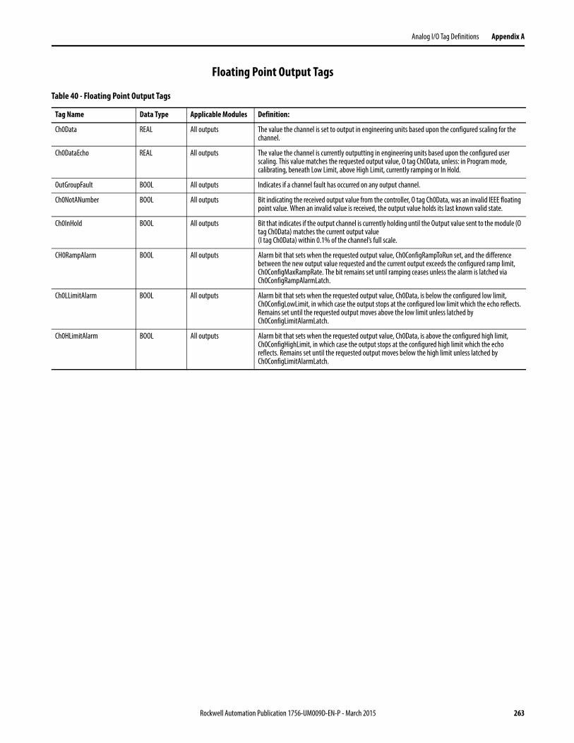
Analog I/O Tag Definitions Appendix A
Floating Point Output Tags
Table 40 - Floating Point Output Tags
Tag Name Data Type Applicable Modules Definition:
Ch0Data REAL All outputs The value the channel is set to output in engineering units based upon the configured scaling for the channel.
Ch0DataEcho REAL All outputs The value the channel is currently outputting in engineering units based upon the configured user scaling. This value matches the requested output value, O tag Ch0Data, unless: in Program mode, calibrating, beneath Low Limit, above High Limit, currently ramping or In Hold.
OutGroupFault BOOL All outputs Indicates if a channel fault has occurred on any output channel.
Ch0NotANumber BOOL All outputs Bit indicating the received output value from the controller, O tag Ch0Data, was an invalid IEEE floating point value. When an invalid value is received, the output value holds its last known valid state.
Ch0InHold BOOL All outputs Bit that indicates if the output channel is currently holding until the Output value sent to the module (O tag Ch0Data) matches the current output value(I tag Ch0Data) within 0.1% of the channel’s full scale.
CH0RampAlarm BOOL All outputs Alarm bit that sets when the requested output value, Ch0ConfigRampToRun set, and the difference between the new output value requested and the current output exceeds the configured ramp limit, Ch0ConfigMaxRampRate. The bit remains set until ramping ceases unless the alarm is latched via Ch0ConfigRampAlarmLatch.
Ch0LLimitAlarm BOOL All outputs Alarm bit that sets when the requested output value, Ch0Data, is below the configured low limit, Ch0ConfigLowLimit, in which case the output stops at the configured low limit which the echo reflects. Remains set until the requested output moves above the low limit unless latched by Ch0ConfigLimitAlarmLatch.
Ch0HLimitAlarm BOOL All outputs Alarm bit that sets when the requested output value, Ch0Data, is above the configured high limit, Ch0ConfigHighLimit, in which case the output stops at the configured high limit which the echo reflects. Remains set until the requested output moves below the high limit unless latched by Ch0ConfigLimitAlarmLatch.
Rockwell Automation Publication 1756-UM009D-EN-P - March 2015 263
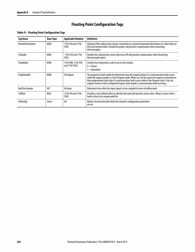
Appendix A Analog I/O Tag Definitions
Floating Point Configuration Tags
Table 41 - Floating Point Configuration Tags
Tag Name Data Type Applicable Modules Definition
RemoteTermination BOOL 1756-IT6I and 1756-IT6I2
Indicates if the cold junction sensor is mounted on a remote termination block when set, rather than on the local terminal block. Needed for proper cold junction compensation when linearizing thermocouples.
CJDisable BOOL 1756-IT6I and 1756-IT6I2
Disables the cold junction sensor that turns off cold junction compensation when linearizing thermocouple inputs.
TempMode BOOL 1756-IR6I, 1756-IT6I and 1756-IT6I2
Controls the temperature scale to use on the module.0 = Celsius1 = Fahrenheit
ProgToFaultEn BOOL All outputs The program to fault enable bit determines how the outputs behave if a communication fault occurs while the output module is in the Program mode. When set, the bit causes the outputs to transition to their programmed Fault state if a communication fault occurs while in the Program state. If not set, outputs remain in their configured Program state despite a communication fault occurring.
RealTimeSample INT All input Determines how often the input signal is to be sampled in terms of milliseconds.
CJOffset REAL 1756-IT6I and 1756-IT6I2
Provides a user-defined offset to add into the read cold-junction sensor value. Allows a sensor with a built-in bias to be compensated for.
Ch0Config Struct All Master structure beneath which the channel’s configuration parametersare set.
264 Rockwell Automation Publication 1756-UM009D-EN-P - March 2015
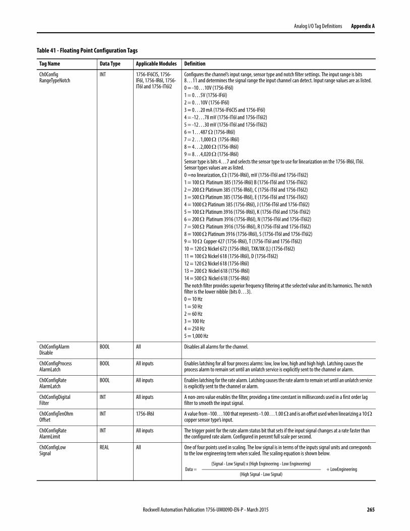
Analog I/O Tag Definitions Appendix A
Ch0ConfigRangeTypeNotch
INT 1756-IF6CIS, 1756-IF6I, 1756-IR6I, 1756-IT6I and 1756-IT6I2
Configures the channel’s input range, sensor type and notch filter settings. The input range is bits 8…11 and determines the signal range the input channel can detect. Input range values are as listed.0 = -10…10V (1756-IF6I)1 = 0…5V (1756-IF6I)2 = 0…10V (1756-IF6I)3 = 0…20 mA (1756-IF6CIS and 1756-IF6I)4 = -12…78 mV (1756-IT6I and 1756-IT6I2)5 = -12…30 mV (1756-IT6I and 1756-IT6I2)6 = 1…487 (1756-IR6I)7 = 2…1,000 (1756-IR6I)8 = 4…2,000 (1756-IR6I)9 = 8…4,020 (1756-IR6I)Sensor type is bits 4…7 and selects the sensor type to use for linearization on the 1756-IR6I, IT6I. Sensor types values are as listed.0 =no linearization, (1756-IR6I), mV (1756-IT6I and 1756-IT6I2)1 = 100 Platinum 385 (1756-IR6I) B (1756-IT6I and 1756-IT6I2)2 = 200 Platinum 385 (1756-IR6I), C (1756-IT6I and 1756-IT6I2)3 = 500 Platinum 385 (1756-IR6I), E (1756-IT6I and 1756-IT6I2)4 = 1000 Platinum 385 (1756-IR6I), J (1756-IT6I and 1756-IT6I2)5 = 100 Platinum 3916 (1756-IR6I), K (1756-IT6I and 1756-IT6I2)6 = 200 Platinum 3916 (1756-IR6I), N (1756-IT6I and 1756-IT6I2)7 = 500 Platinum 3916 (1756-IR6I), R (1756-IT6I and 1756-IT6I2)8 = 1000 Platinum 3916 (1756-IR6I), S (1756-IT6I and 1756-IT6I2)9 = 10 Copper 427 (1756-IR6I), T (1756-IT6I and 1756-IT6I2)10 = 120 Nickel 672 (1756-IR6I), TXK/XK (L) (1756-IT6I2)11 = 100 Nickel 618 (1756-IR6I), D (1756-IT6I2)12 = 120 Nickel 618 (1756-IR6I)13 = 200 Nickel 618 (1756-IR6I)14 = 500 Nickel 618 (1756-IR6I)The notch filter provides superior frequency filtering at the selected value and its harmonics. The notch filter is the lower nibble (bits 0…3).0 = 10 Hz1 = 50 Hz2 = 60 Hz3 = 100 Hz4 = 250 Hz5 = 1,000 Hz
Ch0ConfigAlarmDisable
BOOL All Disables all alarms for the channel.
Ch0ConfigProcessAlarmLatch
BOOL All inputs Enables latching for all four process alarms: low, low low, high and high high. Latching causes the process alarm to remain set until an unlatch service is explicitly sent to the channel or alarm.
Ch0ConfigRateAlarmLatch
BOOL All inputs Enables latching for the rate alarm. Latching causes the rate alarm to remain set until an unlatch service is explicitly sent to the channel or alarm.
Ch0ConfigDigitalFilter
INT All inputs A non-zero value enables the filter, providing a time constant in milliseconds used in a first order lag filter to smooth the input signal.
Ch0ConfigTenOhmOffset
INT 1756-IR6I A value from -100…100 that represents -1.00…1.00 and is an offset used when linearizing a 10 copper sensor type’s input.
Ch0ConfigRateAlarmLimit
INT All inputs The trigger point for the rate alarm status bit that sets if the input signal changes at a rate faster than the configured rate alarm. Configured in percent full scale per second.
Ch0ConfigLowSignal
REAL All One of four points used in scaling. The low signal is in terms of the inputs signal units and corresponds to the low engineering term when scaled. The scaling equation is shown below.
Table 41 - Floating Point Configuration Tags
Tag Name Data Type Applicable Modules Definition
Data = + LowEngineering(Signal - Low Signal) x (High Engineering - Low Engineering)
(High Signal - Low Signal)
Rockwell Automation Publication 1756-UM009D-EN-P - March 2015 265
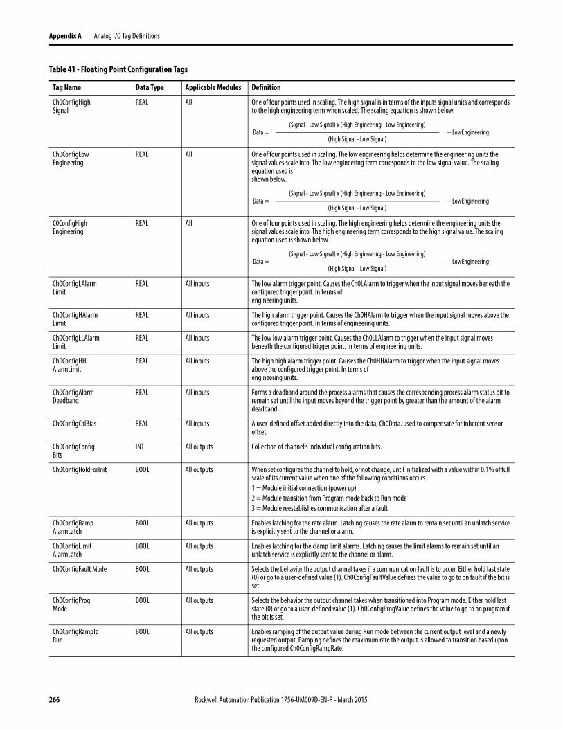
Appendix A Analog I/O Tag Definitions
Ch0ConfigHighSignal
REAL All One of four points used in scaling. The high signal is in terms of the inputs signal units and corresponds to the high engineering term when scaled. The scaling equation is shown below.
Ch0ConfigLowEngineering
REAL All One of four points used in scaling. The low engineering helps determine the engineering units the signal values scale into. The low engineering term corresponds to the low signal value. The scaling equation used isshown below.
C0ConfigHighEngineering
REAL All One of four points used in scaling. The high engineering helps determine the engineering units the signal values scale into. The high engineering term corresponds to the high signal value. The scaling equation used is shown below.
Ch0ConfigLAlarmLimit
REAL All inputs The low alarm trigger point. Causes the Ch0LAlarm to trigger when the input signal moves beneath the configured trigger point. In terms ofengineering units.
Ch0ConfigHAlarmLimit
REAL All inputs The high alarm trigger point. Causes the Ch0HAlarm to trigger when the input signal moves above the configured trigger point. In terms of engineering units.
Ch0ConfigLLAlarmLimit
REAL All inputs The low low alarm trigger point. Causes the Ch0LLAlarm to trigger when the input signal moves beneath the configured trigger point. In terms of engineering units.
Ch0ConfigHHAlarmLimit
REAL All inputs The high high alarm trigger point. Causes the Ch0HHAlarm to trigger when the input signal moves above the configured trigger point. In terms ofengineering units.
Ch0ConfigAlarmDeadband
REAL All inputs Forms a deadband around the process alarms that causes the corresponding process alarm status bit to remain set until the input moves beyond the trigger point by greater than the amount of the alarm deadband.
Ch0ConfigCalBias REAL All inputs A user-defined offset added directly into the data, Ch0Data. used to compensate for inherent sensor offset.
Ch0ConfigConfigBits
INT All outputs Collection of channel’s individual configuration bits.
Ch0ConfigHoldForInit BOOL All outputs When set configures the channel to hold, or not change, until initialized with a value within 0.1% of full scale of its current value when one of the following conditions occurs.1 = Module initial connection (power up)2 = Module transition from Program mode back to Run mode3 = Module reestablishes communication after a fault
Ch0ConfigRampAlarmLatch
BOOL All outputs Enables latching for the rate alarm. Latching causes the rate alarm to remain set until an unlatch service is explicitly sent to the channel or alarm.
Ch0ConfigLimitAlarmLatch
BOOL All outputs Enables latching for the clamp limit alarms. Latching causes the limit alarms to remain set until an unlatch service is explicitly sent to the channel or alarm.
Ch0ConfigFault Mode BOOL All outputs Selects the behavior the output channel takes if a communication fault is to occur. Either hold last state (0) or go to a user-defined value (1). Ch0ConfigFaultValue defines the value to go to on fault if the bit is set.
Ch0ConfigProgMode
BOOL All outputs Selects the behavior the output channel takes when transitioned into Program mode. Either hold last state (0) or go to a user-defined value (1). Ch0ConfigProgValue defines the value to go to on program if the bit is set.
Ch0ConfigRampToRun
BOOL All outputs Enables ramping of the output value during Run mode between the current output level and a newly requested output. Ramping defines the maximum rate the output is allowed to transition based upon the configured Ch0ConfigRampRate.
Table 41 - Floating Point Configuration Tags
Tag Name Data Type Applicable Modules Definition
Data = + LowEngineering(Signal - Low Signal) x (High Engineering - Low Engineering)
(High Signal - Low Signal)
Data = + LowEngineering(Signal - Low Signal) x (High Engineering - Low Engineering)
(High Signal - Low Signal)
Data = + LowEngineering(Signal - Low Signal) x (High Engineering - Low Engineering)
(High Signal - Low Signal)
266 Rockwell Automation Publication 1756-UM009D-EN-P - March 2015
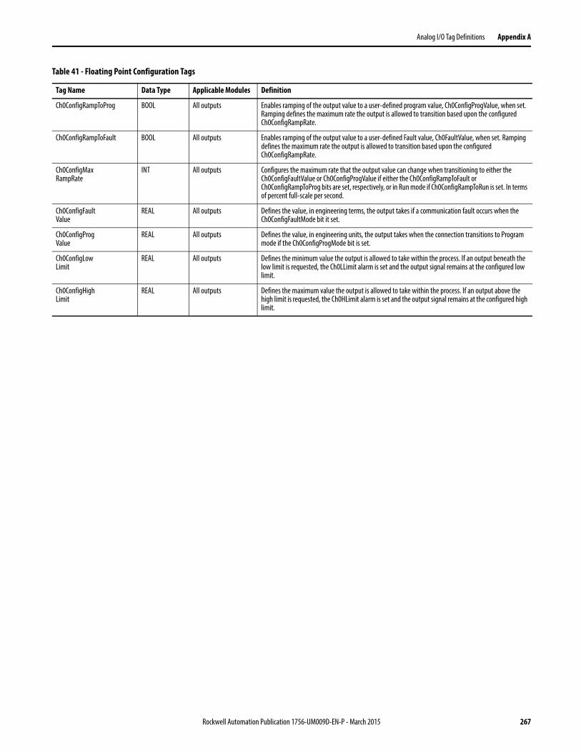
Analog I/O Tag Definitions Appendix A
Ch0ConfigRampToProg BOOL All outputs Enables ramping of the output value to a user-defined program value, Ch0ConfigProgValue, when set. Ramping defines the maximum rate the output is allowed to transition based upon the configured Ch0ConfigRampRate.
Ch0ConfigRampToFault BOOL All outputs Enables ramping of the output value to a user-defined Fault value, Ch0FaultValue, when set. Ramping defines the maximum rate the output is allowed to transition based upon the configured Ch0ConfigRampRate.
Ch0ConfigMaxRampRate
INT All outputs Configures the maximum rate that the output value can change when transitioning to either the Ch0ConfigFaultValue or Ch0ConfigProgValue if either the Ch0ConfigRampToFault or Ch0ConfigRampToProg bits are set, respectively, or in Run mode if Ch0ConfigRampToRun is set. In terms of percent full-scale per second.
Ch0ConfigFaultValue
REAL All outputs Defines the value, in engineering terms, the output takes if a communication fault occurs when the Ch0ConfigFaultMode bit it set.
Ch0ConfigProgValue
REAL All outputs Defines the value, in engineering units, the output takes when the connection transitions to Program mode if the Ch0ConfigProgMode bit is set.
Ch0ConfigLowLimit
REAL All outputs Defines the minimum value the output is allowed to take within the process. If an output beneath the low limit is requested, the Ch0LLimit alarm is set and the output signal remains at the configured low limit.
Ch0ConfigHighLimit
REAL All outputs Defines the maximum value the output is allowed to take within the process. If an output above the high limit is requested, the Ch0HLimit alarm is set and the output signal remains at the configured high limit.
Table 41 - Floating Point Configuration Tags
Tag Name Data Type Applicable Modules Definition
Rockwell Automation Publication 1756-UM009D-EN-P - March 2015 267

Appendix A Analog I/O Tag Definitions
Notes:
268 Rockwell Automation Publication 1756-UM009D-EN-P - March 2015
Appendix B
Use Ladder Logic To Perform Run Time Services and Reconfiguration
You can use ladder logic to perform run time services on your module. For example, page 195 explains how to unlatch alarms on the 1756-IF6I module by using RSLogix 5000 software. This appendix provides an example of how to unlatch those same alarms without using RSLogix 5000 software.
In addition to performing run time services, you can use ladder logic to change configuration. Chapter 10 explains how to use the RSLogix 5000 software to set configuration parameters in your ControlLogix analog I/O module. Some of those parameters also can be changed through ladder logic.
Use Message Instructions In ladder logic, you can use message instructions to send occasional services to any ControlLogix I/O module. Message instructions send an explicit service to the module, causing specific behavior to occur. For example, unlatching a high alarm can be performed by a message instruction.
Message instructions maintain the following characteristics:• Messages use unscheduled portions of system communication bandwidth• One service is performed per instruction• Performing module services does not impede module functionality, such
as sampling inputs or applying new outputs
Process Real-time Control and Module Services
Services sent through message instructions are not as time critical as the module behavior defined during configuration and maintained by a real-time connection. Therefore, the module processes messaging services only after the needs of the I/O connection have been met.
For example, if you want to unlatch all process alarms on the module, real-time control of your process still is occurring by using the input value from that same
Topic Page
Use Message Instructions 269
Process Real-time Control and Module Services 269
One Service Performed Per Instruction 270
Create a New Tag 270
Rockwell Automation Publication 1756-UM009D-EN-P - March 2015 269
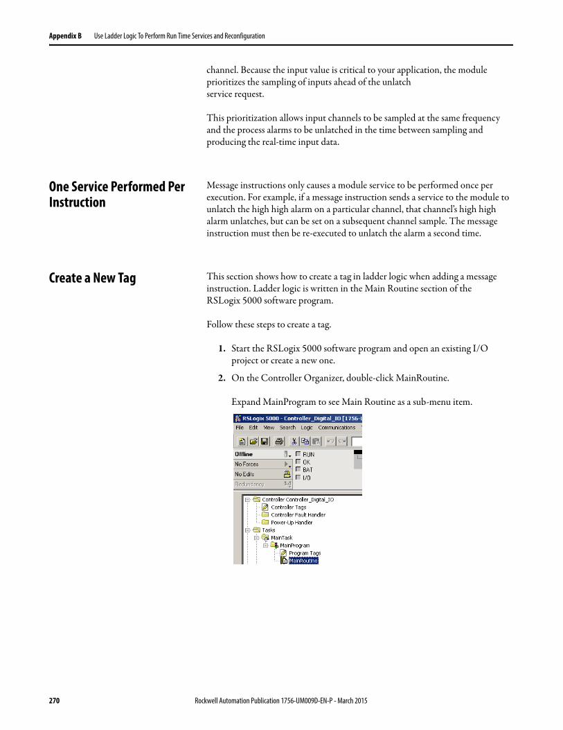
Appendix B Use Ladder Logic To Perform Run Time Services and Reconfiguration
channel. Because the input value is critical to your application, the module prioritizes the sampling of inputs ahead of the unlatchservice request.
This prioritization allows input channels to be sampled at the same frequency and the process alarms to be unlatched in the time between sampling and producing the real-time input data.
One Service Performed Per Instruction
Message instructions only causes a module service to be performed once per execution. For example, if a message instruction sends a service to the module to unlatch the high high alarm on a particular channel, that channel’s high high alarm unlatches, but can be set on a subsequent channel sample. The message instruction must then be re-executed to unlatch the alarm a second time.
Create a New Tag This section shows how to create a tag in ladder logic when adding a message instruction. Ladder logic is written in the Main Routine section of theRSLogix 5000 software program.
Follow these steps to create a tag.
1. Start the RSLogix 5000 software program and open an existing I/O project or create a new one.
2. On the Controller Organizer, double-click MainRoutine.
Expand MainProgram to see Main Routine as a sub-menu item.
270 Rockwell Automation Publication 1756-UM009D-EN-P - March 2015
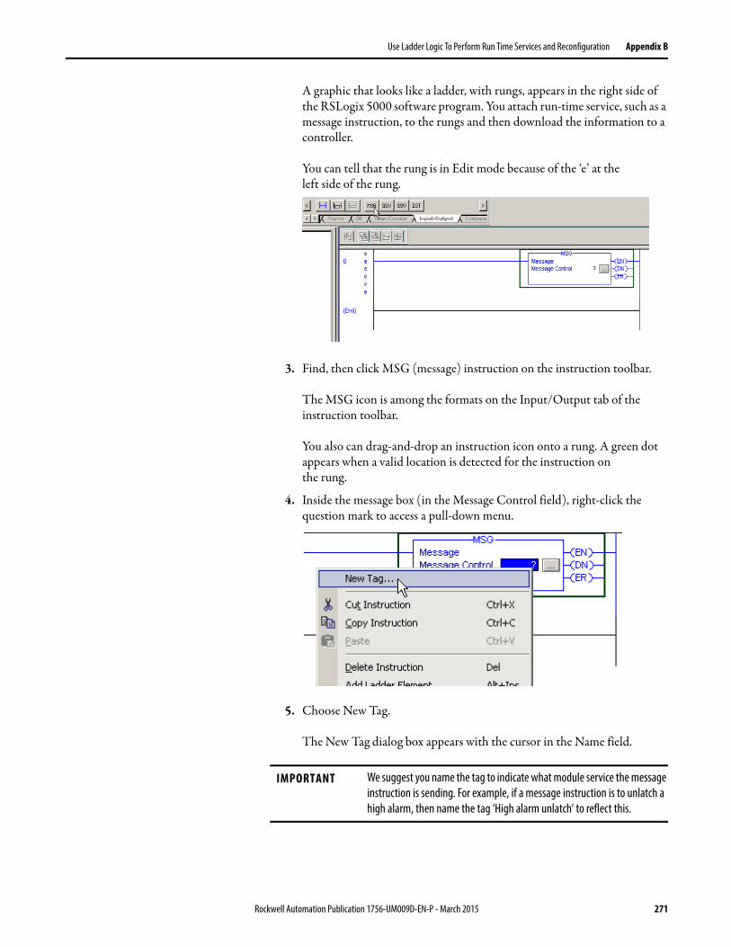
Use Ladder Logic To Perform Run Time Services and Reconfiguration Appendix B
A graphic that looks like a ladder, with rungs, appears in the right side of the RSLogix 5000 software program. You attach run-time service, such as a message instruction, to the rungs and then download the information to a controller.
You can tell that the rung is in Edit mode because of the ‘e’ at theleft side of the rung.
3. Find, then click MSG (message) instruction on the instruction toolbar.
The MSG icon is among the formats on the Input/Output tab of the instruction toolbar.
You also can drag-and-drop an instruction icon onto a rung. A green dot appears when a valid location is detected for the instruction onthe rung.
4. Inside the message box (in the Message Control field), right-click the question mark to access a pull-down menu.
5. Choose New Tag.
The New Tag dialog box appears with the cursor in the Name field.
IMPORTANT We suggest you name the tag to indicate what module service the message instruction is sending. For example, if a message instruction is to unlatch a high alarm, then name the tag ‘High alarm unlatch’ to reflect this.
Rockwell Automation Publication 1756-UM009D-EN-P - March 2015 271
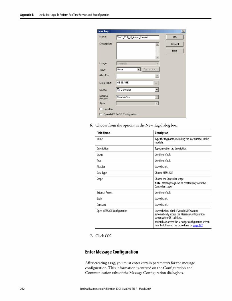
Appendix B Use Ladder Logic To Perform Run Time Services and Reconfiguration
6. Choose from the options in the New Tag dialog box.
7. Click OK.
Enter Message Configuration
After creating a tag, you must enter certain parameters for the message configuration. This information is entered on the Configuration and Communication tabs of the Message Configuration dialog box.
Field Name Description
Name Type the tag name, including the slot number in the module.
Description Type an option tag description.
Usage Use the default.
Type Use the default.
Alias for Leave blank.
Data Type Choose MESSAGE.
Scope Choose the Controller scope.Note: Message tags can be created only with the Controller scope.
External Access Use the default.
Style Leave blank.
Constant Leave blank.
Open MESSAGE Configuration Leave the box blank if you do NOT want to automatically access the Message Configuration screen when OK is clicked.You still can access the Message Configuration screen later by following the procedures on page 272.
272 Rockwell Automation Publication 1756-UM009D-EN-P - March 2015
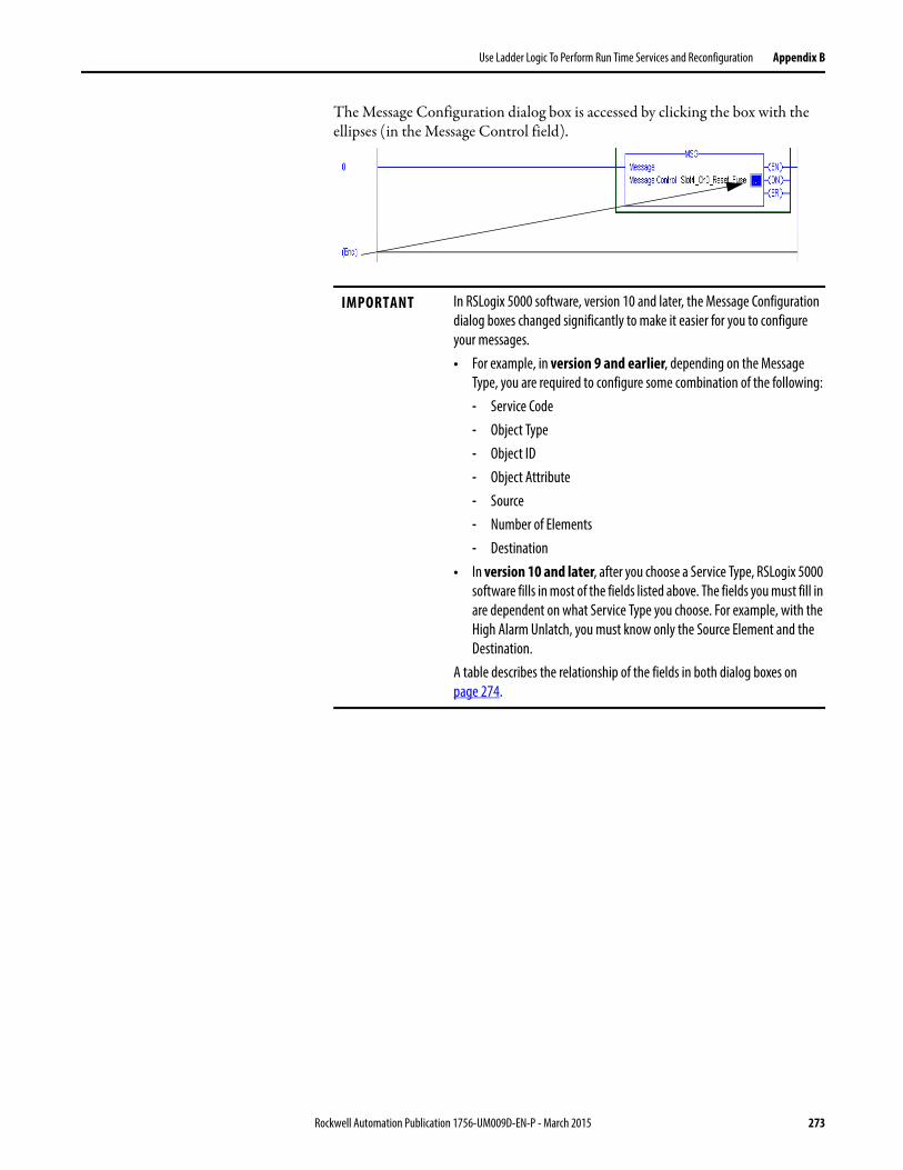
Use Ladder Logic To Perform Run Time Services and Reconfiguration Appendix B
The Message Configuration dialog box is accessed by clicking the box with the ellipses (in the Message Control field).
IMPORTANT In RSLogix 5000 software, version 10 and later, the Message Configuration dialog boxes changed significantly to make it easier for you to configure your messages.• For example, in version 9 and earlier, depending on the Message
Type, you are required to configure some combination of the following:- Service Code- Object Type- Object ID- Object Attribute- Source- Number of Elements- Destination
• In version 10 and later, after you choose a Service Type, RSLogix 5000 software fills in most of the fields listed above. The fields you must fill in are dependent on what Service Type you choose. For example, with the High Alarm Unlatch, you must know only the Source Element and the Destination.
A table describes the relationship of the fields in both dialog boxes on page 274.
Rockwell Automation Publication 1756-UM009D-EN-P - March 2015 273
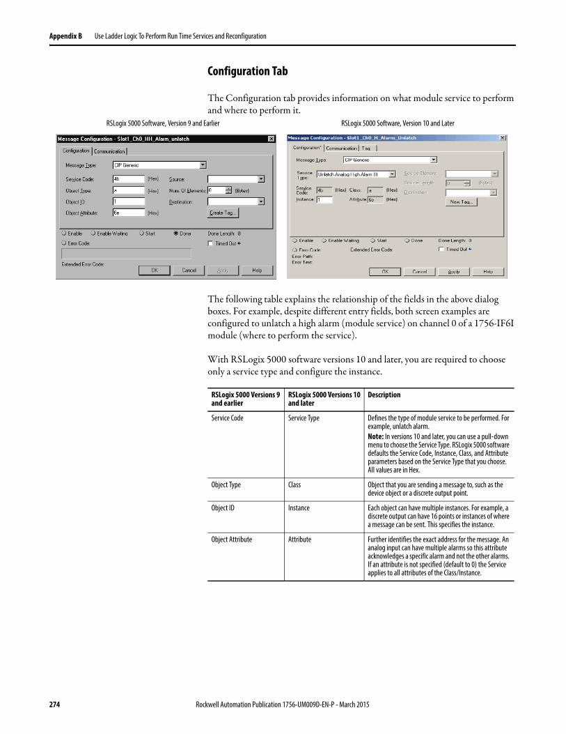
Appendix B Use Ladder Logic To Perform Run Time Services and Reconfiguration
Configuration Tab
The Configuration tab provides information on what module service to perform and where to perform it.
The following table explains the relationship of the fields in the above dialog boxes. For example, despite different entry fields, both screen examples are configured to unlatch a high alarm (module service) on channel 0 of a 1756-IF6I module (where to perform the service).
With RSLogix 5000 software versions 10 and later, you are required to choose only a service type and configure the instance.
RSLogix 5000 Software, Version 9 and Earlier RSLogix 5000 Software, Version 10 and Later
RSLogix 5000 Versions 9and earlier
RSLogix 5000 Versions 10and later
Description
Service Code Service Type Defines the type of module service to be performed. For example, unlatch alarm.Note: In versions 10 and later, you can use a pull-down menu to choose the Service Type. RSLogix 5000 software defaults the Service Code, Instance, Class, and Attribute parameters based on the Service Type that you choose. All values are in Hex.
Object Type Class Object that you are sending a message to, such as the device object or a discrete output point.
Object ID Instance Each object can have multiple instances. For example, a discrete output can have 16 points or instances of where a message can be sent. This specifies the instance.
Object Attribute Attribute Further identifies the exact address for the message. An analog input can have multiple alarms so this attribute acknowledges a specific alarm and not the other alarms. If an attribute is not specified (default to 0) the Service applies to all attributes of the Class/Instance.
274 Rockwell Automation Publication 1756-UM009D-EN-P - March 2015
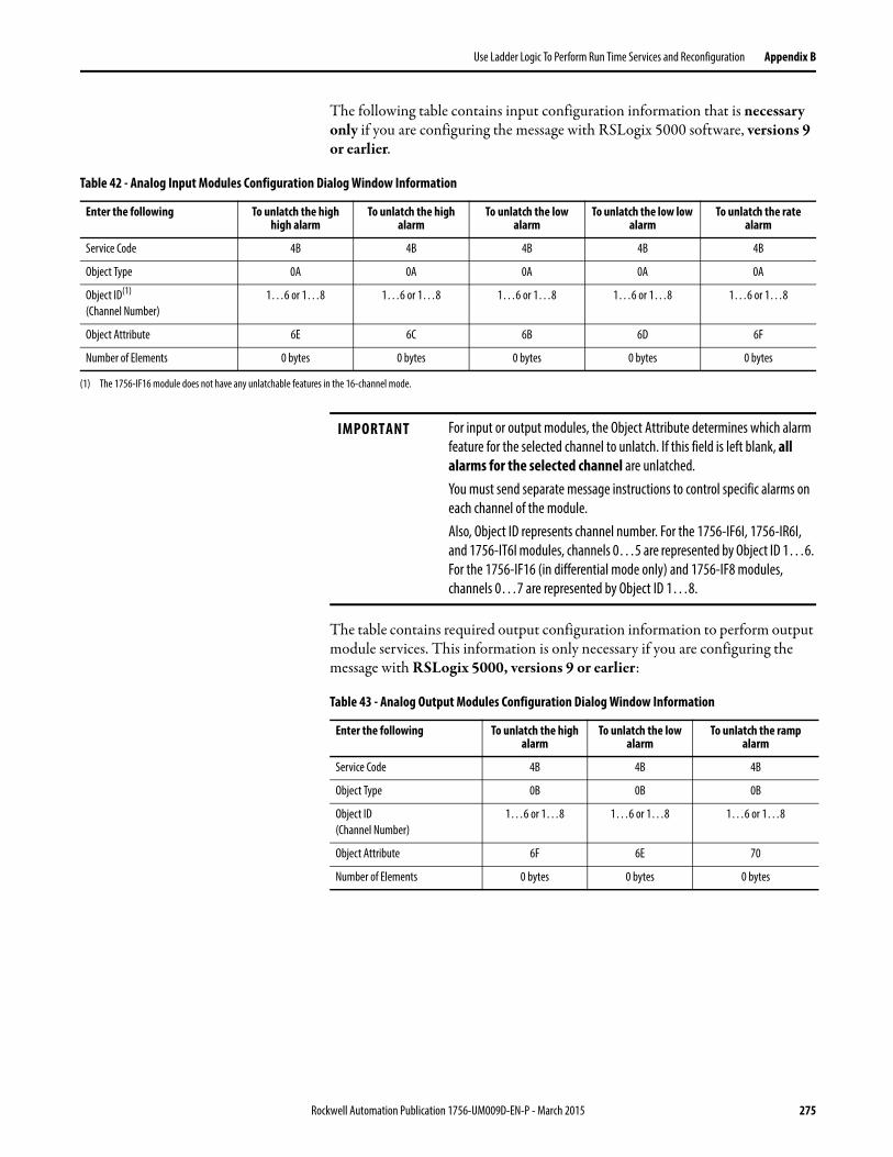
Use Ladder Logic To Perform Run Time Services and Reconfiguration Appendix B
The following table contains input configuration information that is necessary only if you are configuring the message with RSLogix 5000 software, versions 9 or earlier.
The table contains required output configuration information to perform output module services. This information is only necessary if you are configuring the message with RSLogix 5000, versions 9 or earlier:
Table 42 - Analog Input Modules Configuration Dialog Window Information
Enter the following To unlatch the high high alarm
To unlatch the high alarm
To unlatch the low alarm
To unlatch the low low alarm
To unlatch the rate alarm
Service Code 4B 4B 4B 4B 4B
Object Type 0A 0A 0A 0A 0A
Object ID(1)
(Channel Number)1…6 or 1…8 1…6 or 1…8 1…6 or 1…8 1…6 or 1…8 1…6 or 1…8
Object Attribute 6E 6C 6B 6D 6F
Number of Elements 0 bytes 0 bytes 0 bytes 0 bytes 0 bytes
(1) The 1756-IF16 module does not have any unlatchable features in the 16-channel mode.
IMPORTANT For input or output modules, the Object Attribute determines which alarm feature for the selected channel to unlatch. If this field is left blank, all alarms for the selected channel are unlatched.You must send separate message instructions to control specific alarms on each channel of the module.Also, Object ID represents channel number. For the 1756-IF6I, 1756-IR6I, and 1756-IT6I modules, channels 0…5 are represented by Object ID 1…6. For the 1756-IF16 (in differential mode only) and 1756-IF8 modules, channels 0…7 are represented by Object ID 1…8.
Table 43 - Analog Output Modules Configuration Dialog Window Information
Enter the following To unlatch the high alarm
To unlatch the low alarm
To unlatch the ramp alarm
Service Code 4B 4B 4B
Object Type 0B 0B 0B
Object ID(Channel Number)
1…6 or 1…8 1…6 or 1…8 1…6 or 1…8
Object Attribute 6F 6E 70
Number of Elements 0 bytes 0 bytes 0 bytes
Rockwell Automation Publication 1756-UM009D-EN-P - March 2015 275
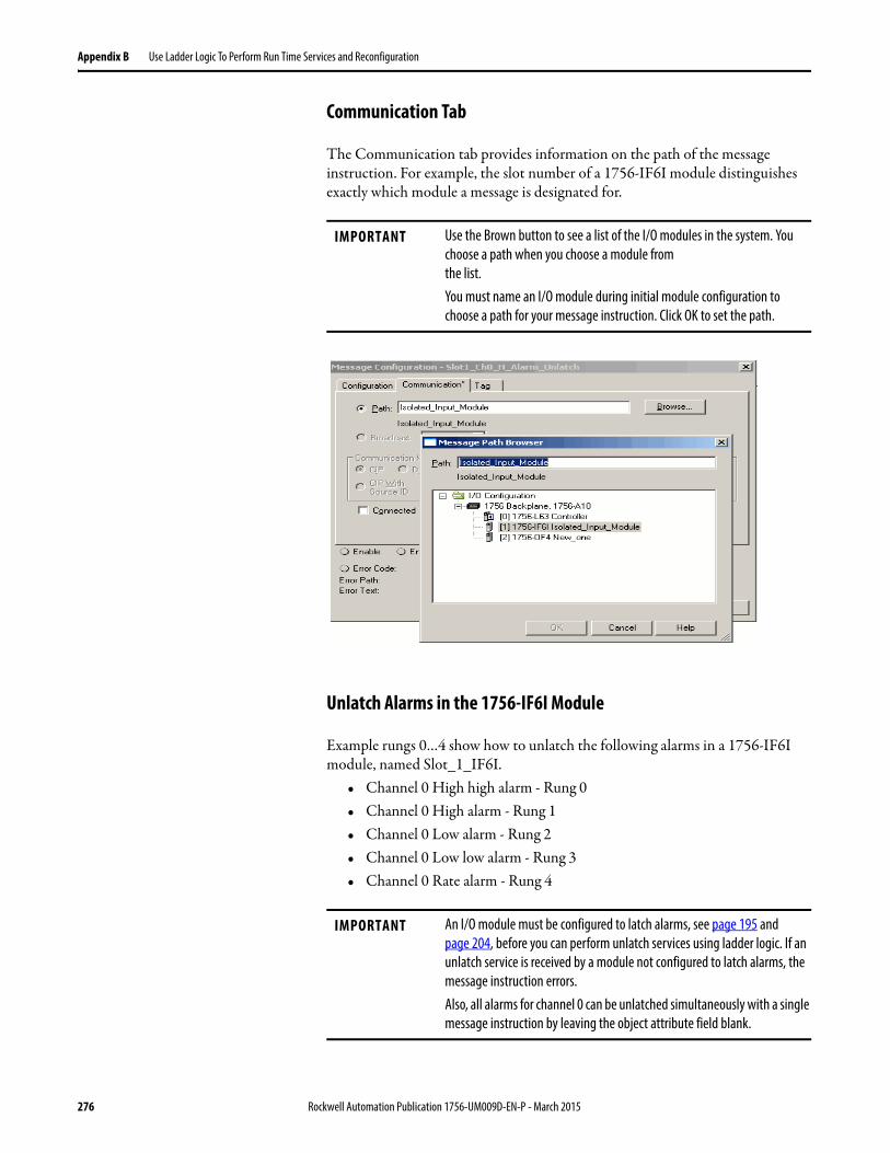
Appendix B Use Ladder Logic To Perform Run Time Services and Reconfiguration
Communication Tab
The Communication tab provides information on the path of the message instruction. For example, the slot number of a 1756-IF6I module distinguishes exactly which module a message is designated for.
Unlatch Alarms in the 1756-IF6I Module
Example rungs 0…4 show how to unlatch the following alarms in a 1756-IF6I module, named Slot_1_IF6I.
• Channel 0 High high alarm - Rung 0• Channel 0 High alarm - Rung 1• Channel 0 Low alarm - Rung 2• Channel 0 Low low alarm - Rung 3• Channel 0 Rate alarm - Rung 4
IMPORTANT Use the Brown button to see a list of the I/O modules in the system. You choose a path when you choose a module fromthe list.You must name an I/O module during initial module configuration to choose a path for your message instruction. Click OK to set the path.
IMPORTANT An I/O module must be configured to latch alarms, see page 195 and page 204, before you can perform unlatch services using ladder logic. If an unlatch service is received by a module not configured to latch alarms, the message instruction errors.Also, all alarms for channel 0 can be unlatched simultaneously with a single message instruction by leaving the object attribute field blank.
276 Rockwell Automation Publication 1756-UM009D-EN-P - March 2015
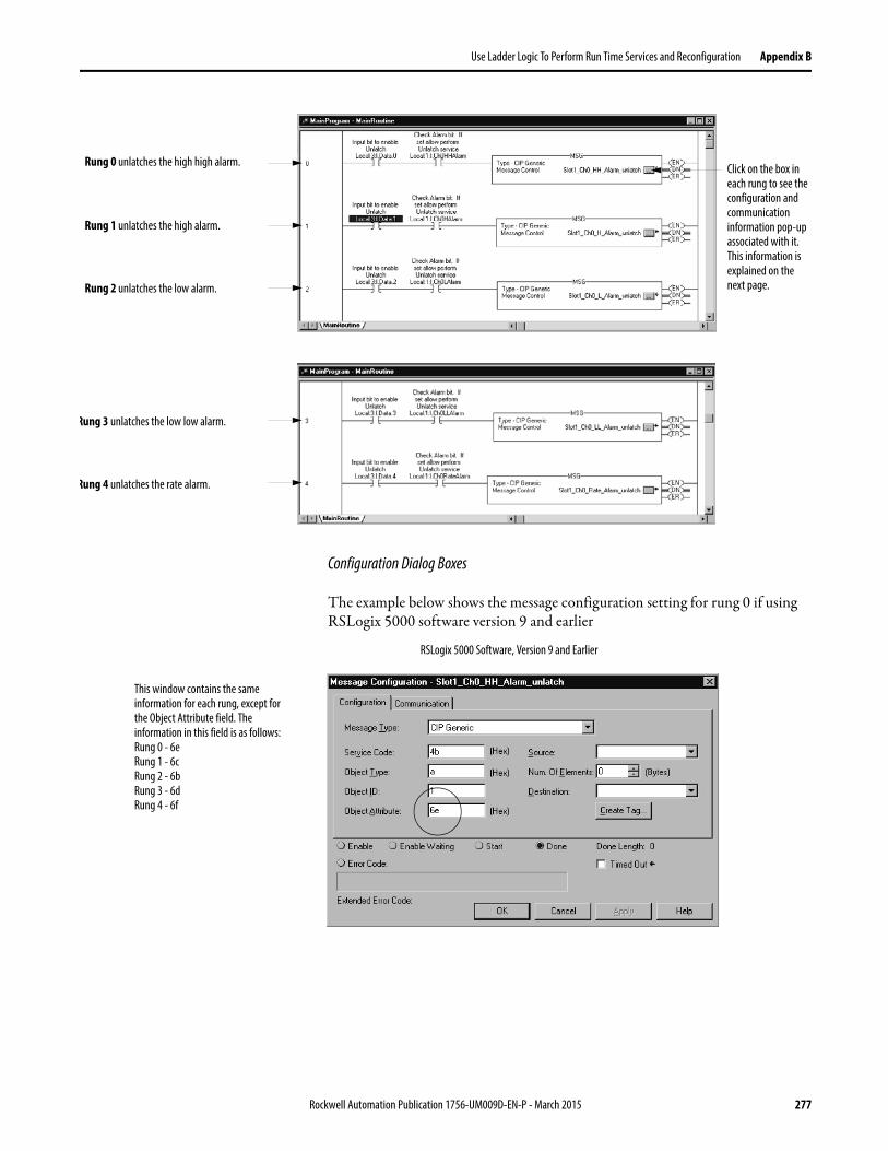
Use Ladder Logic To Perform Run Time Services and Reconfiguration Appendix B
Configuration Dialog Boxes
The example below shows the message configuration setting for rung 0 if using RSLogix 5000 software version 9 and earlier
Rung 0 unlatches the high high alarm.
Rung 1 unlatches the high alarm.
Rung 2 unlatches the low alarm.
Rung 3 unlatches the low low alarm.
Rung 4 unlatches the rate alarm.
Click on the box in each rung to see the configuration and communication information pop-up associated with it. This information is explained on the next page.
This window contains the same information for each rung, except for the Object Attribute field. The information in this field is as follows:Rung 0 - 6eRung 1 - 6cRung 2 - 6bRung 3 - 6dRung 4 - 6f
RSLogix 5000 Software, Version 9 and Earlier
Rockwell Automation Publication 1756-UM009D-EN-P - March 2015 277
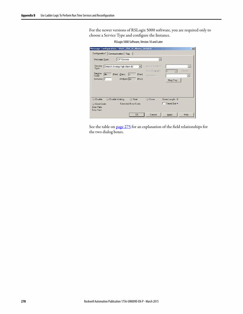
Appendix B Use Ladder Logic To Perform Run Time Services and Reconfiguration
For the newer versions of RSLogix 5000 software, you are required only to choose a Service Type and configure the Instance.
See the table on page 275 for an explanation of the field relationships forthe two dialog boxes.
RSLogix 5000 Software, Version 10 and Later
278 Rockwell Automation Publication 1756-UM009D-EN-P - March 2015

Use Ladder Logic To Perform Run Time Services and Reconfiguration Appendix B
Communication Dialog Boxes
The examples show the Communication dialog boxes for different versions of RSLogix 5000 software.
The top example is for rung 0 if using RSLogix 5000, version 9 and earlier. The window is the same for each rung of this example.
Unlatch Alarms in the 1756-OF6VI Module
Example rungs 5…7 show how to unlatch the following alarms in a 1756-OF6VI module:
• High limit alarm - Rung 5• Low limit alarm - Rung 6
RSLogix 5000 Software, Version 9 and Earlier
RSLogix 5000 Software, Version 10 and Later
IMPORTANT You must name an I/O module to set the message path under that module’s communication tab.
Rockwell Automation Publication 1756-UM009D-EN-P - March 2015 279
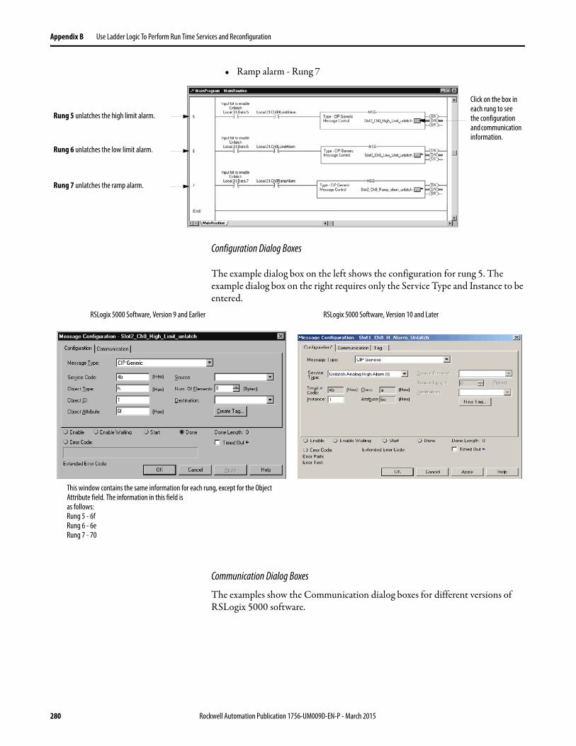
Appendix B Use Ladder Logic To Perform Run Time Services and Reconfiguration
• Ramp alarm - Rung 7
Configuration Dialog Boxes
The example dialog box on the left shows the configuration for rung 5. The example dialog box on the right requires only the Service Type and Instance to be entered.
Communication Dialog Boxes
The examples show the Communication dialog boxes for different versions of RSLogix 5000 software.
Rung 5 unlatches the high limit alarm.
Rung 6 unlatches the low limit alarm.
Rung 7 unlatches the ramp alarm.
Click on the box in each rung to see the configuration and communication information.
This window contains the same information for each rung, except for the Object Attribute field. The information in this field isas follows:Rung 5 - 6fRung 6 - 6eRung 7 - 70
RSLogix 5000 Software, Version 9 and Earlier RSLogix 5000 Software, Version 10 and Later
280 Rockwell Automation Publication 1756-UM009D-EN-P - March 2015
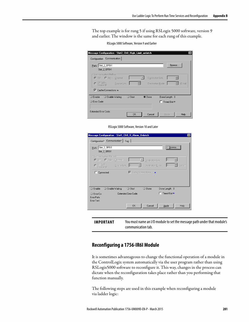
Use Ladder Logic To Perform Run Time Services and Reconfiguration Appendix B
The top example is for rung 5 if using RSLogix 5000 software, version 9and earlier. The window is the same for each rung of this example.
Reconfiguring a 1756-IR6I Module
It is sometimes advantageous to change the functional operation of a module in the ControlLogix system automatically via the user program rather than using RSLogix5000 software to reconfigure it. This way, changes in the process can dictate when the reconfiguration takes place rather than you performing that function manually.
The following steps are used in this example when reconfiguring a modulevia ladder logic:
RSLogix 5000 Software, Version 9 and Earlier
RSLogix 5000 Software, Version 10 and Later
IMPORTANT You must name an I/O module to set the message path under that module’s communication tab.
Rockwell Automation Publication 1756-UM009D-EN-P - March 2015 281
Appendix B Use Ladder Logic To Perform Run Time Services and Reconfiguration
1. Move new configuration parameters to the Configuration portion of the Tag Structure associated with the module.
2. If you are using RSLogix 5000 software, version 10 or later, use a message instruction to send a Reconfigure Module service to the same module.
If you are using RSLogix 5000 software, version 9 or earlier, use a message instruction to send a Reset Module service to the same module to trigger sending the configuration data.
Before the new configuration parameters are sent to the module, you must make sure that their relationship to each other is in a format the module accepts (see tables on page 283).
IMPORTANT Limit reconfiguring analog modules via ladder logic should be limited to functions that involve only the changing of values. We do not recommend that enabling or disabling features be done via ladder logic. Use RSLogix 5000 software to enable or disable these features.
282 Rockwell Automation Publication 1756-UM009D-EN-P - March 2015
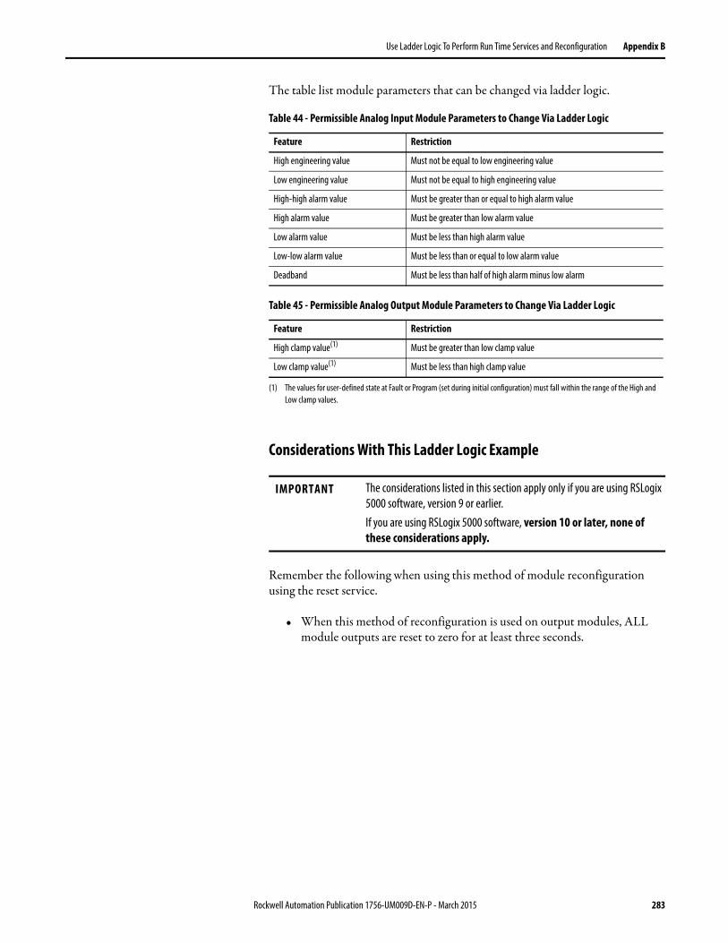
Use Ladder Logic To Perform Run Time Services and Reconfiguration Appendix B
The table list module parameters that can be changed via ladder logic.
Considerations With This Ladder Logic Example
Remember the following when using this method of module reconfiguration using the reset service.
• When this method of reconfiguration is used on output modules, ALL module outputs are reset to zero for at least three seconds.
Table 44 - Permissible Analog Input Module Parameters to Change Via Ladder Logic
Feature Restriction
High engineering value Must not be equal to low engineering value
Low engineering value Must not be equal to high engineering value
High-high alarm value Must be greater than or equal to high alarm value
High alarm value Must be greater than low alarm value
Low alarm value Must be less than high alarm value
Low-low alarm value Must be less than or equal to low alarm value
Deadband Must be less than half of high alarm minus low alarm
Table 45 - Permissible Analog Output Module Parameters to Change Via Ladder Logic
Feature Restriction
High clamp value(1)
(1) The values for user-defined state at Fault or Program (set during initial configuration) must fall within the range of the High and Low clamp values.
Must be greater than low clamp value
Low clamp value(1) Must be less than high clamp value
IMPORTANT The considerations listed in this section apply only if you are using RSLogix 5000 software, version 9 or earlier.If you are using RSLogix 5000 software, version 10 or later, none of these considerations apply.
Rockwell Automation Publication 1756-UM009D-EN-P - March 2015 283
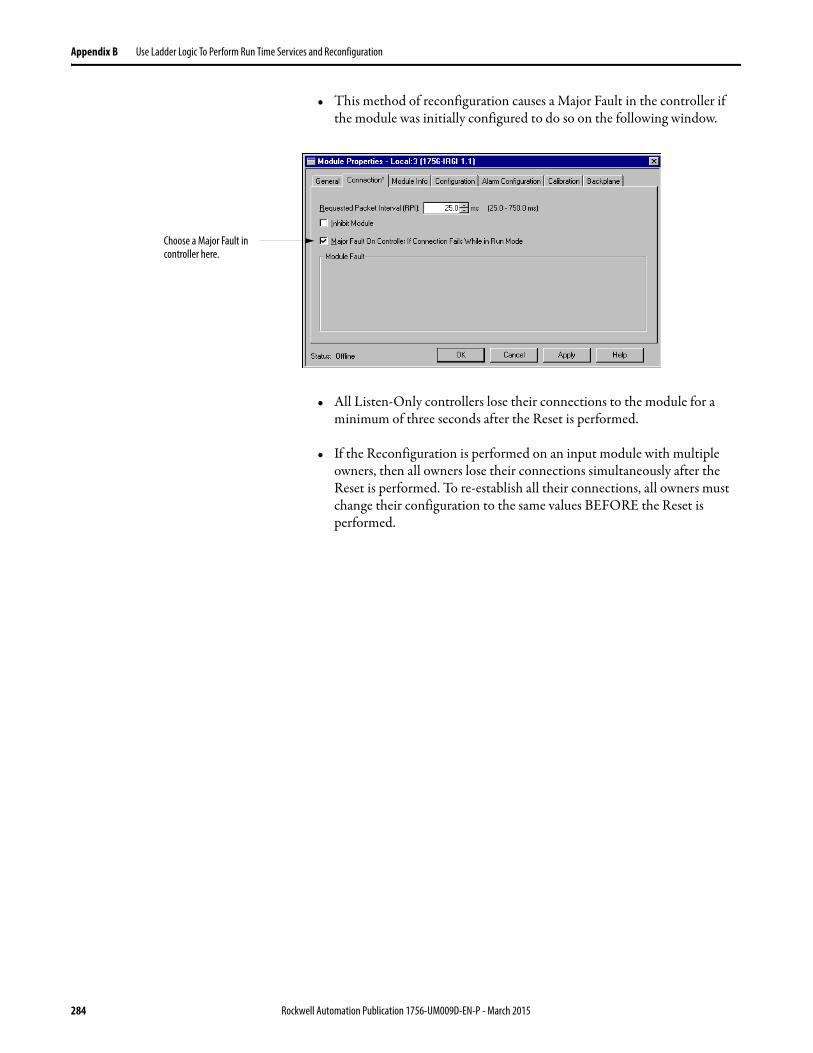
Appendix B Use Ladder Logic To Perform Run Time Services and Reconfiguration
• This method of reconfiguration causes a Major Fault in the controller if the module was initially configured to do so on the following window.
• All Listen-Only controllers lose their connections to the module for a minimum of three seconds after the Reset is performed.
• If the Reconfiguration is performed on an input module with multiple owners, then all owners lose their connections simultaneously after the Reset is performed. To re-establish all their connections, all owners must change their configuration to the same values BEFORE the Reset is performed.
Choose a Major Fault in controller here.
284 Rockwell Automation Publication 1756-UM009D-EN-P - March 2015
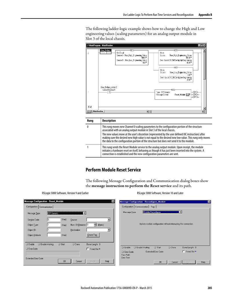
Use Ladder Logic To Perform Run Time Services and Reconfiguration Appendix B
The following ladder-logic example shows how to change the High and Low engineering values (scaling parameters) for an analog output module inSlot 3 of the local chassis.
Perform Module Reset Service
The following Message Configuration and Communication dialog boxes show the message instruction to perform the Reset service and its path.
Rung Description
0 This rung moves new Channel 0 scaling parameters to the configuration portion of the structure associated with an analog output module in Slot 3 of the local chassis.The new values move at the user’s discretion (represented by the user defined XIC instruction) after making sure the desired new high value is not equal to the desired new low value. This rung only moves the data to the configuration portion of the structure but does not send it to the module.
1 This rung sends the Reset Module service to the analog output module. Upon receipt, the module initiates a hardware reset on itself, behaving as though it has just been inserted into the system. A connection is established and the new configuration parameters are sent.
RSLogix 5000 Software, Version 9 and Earlier RSLogix 5000 Software, Version 10 and Later
Rockwell Automation Publication 1756-UM009D-EN-P - March 2015 285
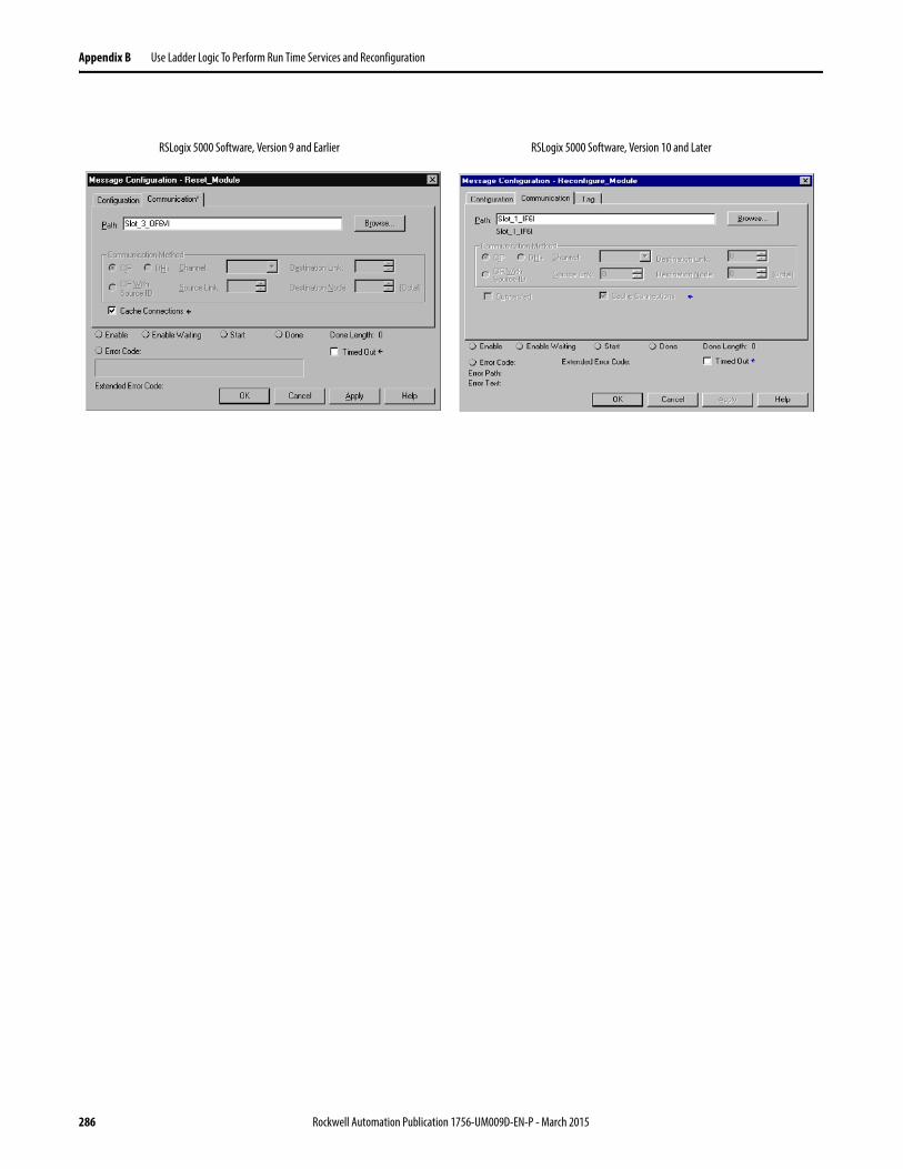
Appendix B Use Ladder Logic To Perform Run Time Services and Reconfiguration
RSLogix 5000 Software, Version 10 and LaterRSLogix 5000 Software, Version 9 and Earlier
286 Rockwell Automation Publication 1756-UM009D-EN-P - March 2015
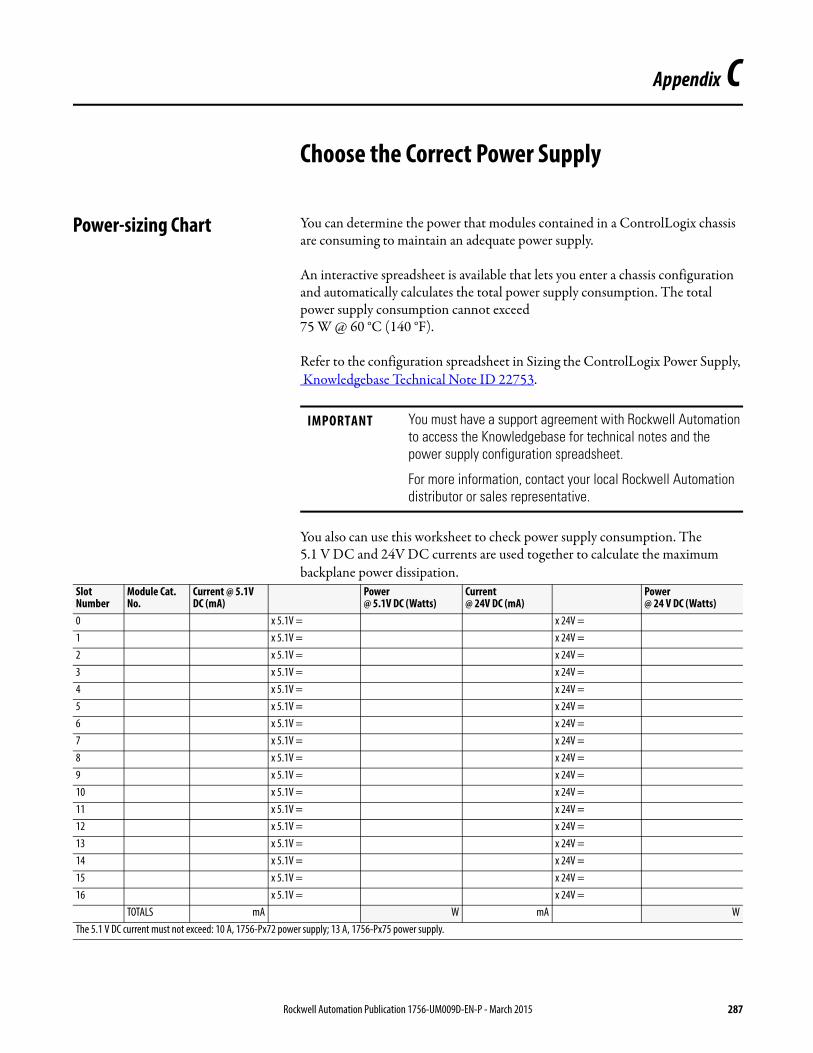
Appendix C
Choose the Correct Power Supply
Power-sizing Chart You can determine the power that modules contained in a ControlLogix chassis are consuming to maintain an adequate power supply.
An interactive spreadsheet is available that lets you enter a chassis configuration and automatically calculates the total power supply consumption. The total power supply consumption cannot exceed75 W @ 60 °C (140 °F).
Refer to the configuration spreadsheet in Sizing the ControlLogix Power Supply, Knowledgebase Technical Note ID 22753.
You also can use this worksheet to check power supply consumption. The5.1 V DC and 24V DC currents are used together to calculate the maximum backplane power dissipation.
IMPORTANT You must have a support agreement with Rockwell Automation to access the Knowledgebase for technical notes and the power supply configuration spreadsheet.
For more information, contact your local Rockwell Automation distributor or sales representative.
Slot Number
Module Cat. No.
Current @ 5.1V DC (mA)
Power@ 5.1V DC (Watts)
Current@ 24V DC (mA)
Power@ 24 V DC (Watts)
0 x 5.1V = x 24V =1 x 5.1V = x 24V =2 x 5.1V = x 24V =3 x 5.1V = x 24V =4 x 5.1V = x 24V =5 x 5.1V = x 24V =6 x 5.1V = x 24V =7 x 5.1V = x 24V =8 x 5.1V = x 24V =9 x 5.1V = x 24V =10 x 5.1V = x 24V =11 x 5.1V = x 24V =12 x 5.1V = x 24V =13 x 5.1V = x 24V =14 x 5.1V = x 24V =15 x 5.1V = x 24V =16 x 5.1V = x 24V =
TOTALS mA W mA WThe 5.1 V DC current must not exceed: 10 A, 1756-Px72 power supply; 13 A, 1756-Px75 power supply.
Rockwell Automation Publication 1756-UM009D-EN-P - March 2015 287

Appendix C Choose the Correct Power Supply
Notes:
288 Rockwell Automation Publication 1756-UM009D-EN-P - March 2015
Appendix D
Additional Specification Information
This appendix offers additional calibration information that can assist you in using the ControlLogix analog I/O module.
Analog to Digital (A/D) Converter Accuracy
There are two types of calibration that occur on a ControlLogixanalog I/O module.
• The user-directed and user-performed calibration process described in Chapter 11. This type of calibration occurs only when you determine it is necessary and involves an external calibration instrument like those listed on page 214.
• A self-calibration process that takes place internally on ControlLogix analog I/O modules when either of the following events occurs:
– Module power is cycled.– You begin the user calibration described in Chapter 11.
The ‘A/D self-calibration’ feature maintains the accuracy of the A/D convertor found on all 1756 isolated analog modules. This feature executes each time the module cycles power or when a self-calibration cycle is initiated.
The self-calibration compensates for inaccuracies of the on-board reference signal and the A/D convertor only. In other words, the self-calibration feature makes sure that the A/D convertor itself is accurate with respect to its on-board voltage reference that is used for a conversion of the input signal. Together with user calibration, the module’s total accuracy is maintained.
Topic Page
Analog to Digital (A/D) Converter Accuracy 289
Calibrated Accuracy 290
Error Calculated Over Hardware Range 291
How Operating Temperature Changes Affect Module Accuracy 291
RTD and Thermocouple Error Calculations 293
Thermocouple Resolution 301
Rockwell Automation Publication 1756-UM009D-EN-P - March 2015 289
Appendix D Additional Specification Information
Calibrated Accuracy The Calibrated Accuracy specification represents the module’s accuracy when its ambient (that is, operating) temperature is the same as the temperature at which the module was calibrated.
Immediately following a calibration, a ControlLogix analog I/O module is most accurate. Because the module was calibrated at its zero and span, the inaccuracy is largely non-linearity between zero and span. Assuming the module is operating at the exact temperature when it was calibrated and uses the same voltage source to check the post-calibration accuracy, a module can be as accurate as 0.01…0.05% of range.
Once the module begins operation, its accuracy lessens as components change over time. However, this change (in components or accuracy) is different from the Gain Drift With Temperature specification described on page 291.
Other than non-linearity, the Calibrated Accuracy @ 25 °C (77 °F) specification represents a time drift/aging specification between calibrations. A module with a calibration accuracy of 0.01% of range immediately following calibration is estimated to be better than 0.1% of range @ 25 °C (77 °F) for one year (that is, the calibration cycle).
The reason for the difference between 0.01% and 0.1% of range is that the Calibrated Accuracy @ 25 °C (77 °F) specification must capture the effect of component aging until the next time the module is calibrated. Primarily, the module's operating conditions, such as temperature, humidity, and power cycling, affect component aging.
Because ControlLogix analog I/O modules operate in different conditions, the specific accuracy deviation from 0.01% of range cannot be measured. Typically, however, a module’s Calibrated Accuracy @ 25 °C (77 °F) is closer to 0.05% of range than 0.1% of range as the 0.1% of range is determined by the worst case scenario operating conditions.
290 Rockwell Automation Publication 1756-UM009D-EN-P - March 2015
Additional Specification Information Appendix D
Error Calculated Over Hardware Range
A ControlLogix analog I/O module’s calibration accuracy at 25 °C (77 °F) is calculated over the full hardware range of the module and is not dependent on the application’s use of the range. The error is the same if you are measuring it across a 10% or 100% portion of a given range.
However, a module’s accuracy at 25 °C (77 °F) is dependent on the hardware range in which the module operates.
How Operating Temperature Changes Affect Module Accuracy
The following specifications take into account how the module’s operating temperature changes can affect a module’s accuracy.
• Gain Drift With Temperature• Module Error Over Full Temperature Range
Gain Drift With Temperature
The Gain Drift with Temperature specification represents the calibration inaccuracy that occurs as a module’s ambient (that is, operating) temperature drifts from the temperature at which it was calibrated.
You can use the Gain Drift with Temperature specification (varies for each catalog number) to determine the module’s calibration inaccuracy for each degree between calibration and operating temperature. The Gain Drift with Temperature specification represents a percentage of the full operating range that the module’s calibration is inaccurate to for each degree difference. The specification is determined with the following formula:
Gain Drift with Temperature = (PPM/°C) x Module’s Full Range
EXAMPLE The 1756-IT6I module offers two input ranges, -12…30 mV and -12 …78 mV. Because module error at 25 °C (77 °F) depends on the input range used, the module error is as follows when using 0.1% of range accuracy:
• +/- 42 mV for the -12…30 mV range• +/- 90 mV for the -12…78 mV range
These error values are the same whether you use 10% or 100% of the chosen range.
Rockwell Automation Publication 1756-UM009D-EN-P - March 2015 291
Appendix D Additional Specification Information
Because the specifications listed in publication 1756-TD002 include a typical and worst case PPM/ °C for each module, you can determine multiple Gain Drift with Temperature values for each module.
Module Error Over Full Temperature Range
The Module Error Over Full Temperature Range specification represents the error that occurs if the module’s ambient temperature changes a total of60 °C (that is, from 0…60 °C (0…140 °F) or 60…0 °C). While this temperature change is extremely unlikely, it represents the worst case scenario.
This specification is determined by multiplying the temperature change by the maximum Gain Drift with Temperature for the given module. In other words, we determine Module Error Over Full Temperature Range with thefollowing formula:
Module Error Over Full Temperature = Full Temperature Range x Gain Drift with Temperature
EXAMPLE For example, the 1756-IT6I module has a maximum Gain Drift with Temperature specification of 80 ppm/ °C. The 80 ppm represents 0.008% of the module’s full operating temperature.
ATTENTION: If the module was calibrated to operate in the -12…78mV input range, then following formula is used:(0.008/ °C) x 90 mV = +/-7.2 μV/ °CATTENTION: For every degree Celsius that the module’s operating temperature moves from the calibration temperature, the maximum calibration accuracy deviation is +/-7.2 μV.
EXAMPLE The 1756-IT6I module has a maximum Gain Drift with Temperature specification = 80 ppm/ °C.
ATTENTION: Module Error over Full Temperature Range = 60 °C (full temperature range) X 80 ppm/ °C (gain drift). The result is4800 ppm or 0.48%.
292 Rockwell Automation Publication 1756-UM009D-EN-P - March 2015
Additional Specification Information Appendix D
RTD and Thermocouple Error Calculations
When you use the temperature-measuring modules (1756-IR6I, 1756-IT6I, and 1756-IT6I2), error calculations are achieved in a two-step process.
1. Calculate the module’s error in ohms or volts.
2. Convert the ohm/volt error to temperature for the specific sensor and at the correct application temperature.
RTD Error
Module error on the 1756-IR6I module is defined in ohms and is calculated across the entire input range selected, not the available range of a sensor used with the module. For example, if the 1…487 input range is used, the module error is calculated across 507 (actual range = 0.86…507.86 ).
The error in ohms translates to temperature, but that translation varies because the relationship is non-linear. The most effective way to check 1756-IR6I module error is to calculate the error in ohms and use that value in a linearization table to check the temperature error.
If the module is calibrated at operating temperature and the operating temperature remains relatively stable, calibration accuracy is better than 0.1% of the full range for the first year after calibration. This 0.1% value is a worst case value. In other words, with the 1…487 input range selected, the worst case module error is 0.507 .
Finally, you must check an RTD linearization table to determine the temperature error to which an error of 0.507 translates. For example, if the 1756-IR6I has a 0.1% (or 0.507 ) error and is operating at 0 °C (32 °F), the temperature error is -1.25…1.2 °C (-2.25…2.16 °F) when the Platinum 385 sensor type is used. However, this same ohms error calculated in an operating temperature of 200 °C (392 °F) translates to a temperature error of-1.4 °C…1.4 °C (-2.52…2.52 °F).
Rockwell Automation Publication 1756-UM009D-EN-P - March 2015 293
Appendix D Additional Specification Information
Thermocouple Error
Thermocouple error at 25 °C (77 °F) indicates the module’s accuracy in measuring temperature. This accuracy varies depending on these factors:
• Input range used, either:– -12…30 mV– -12…78 mV
• Thermocouple type, any of the following:– B, R, S, E, J, K, N, T, L or D (L and D types can be used with the 1756-
IT6I2 only)
• Application temperature (that is, the temperature of the physical location where the thermocouple is being used)
EXAMPLE For example, when the 1756-IT6I module is operating in the following conditions:
• -12…30 mV input range• connected to a type S thermocouple• application temperature of 1200 °C (2192 °F)
the module error at 25 °C (77 °F) is +/-1.75 degrees.
In other words, the difference between the temperature the module reports and the actual application temperature can be +/- 1.75 degrees.
The module can report an application temperature of1200 °C (2192 °F) in this case when the actual temperature can be in the range from 1196.26…1203.74 °C (2185.268…2198.732 °F).
IMPORTANT When determining the thermocouple error, we used a typical error of 0.05% of temperature range. The error calculations are listed for each range (that is, -12…30 mV and -12…78 mV) in the rest of this section.
However, keep in mind that if cold junction compensation is performed on the thermocouple modules, the cold junction sensor error values must be added to the +/-1.75 degrees value in the example above and the numbers listed in the rest ofthis section.
294 Rockwell Automation Publication 1756-UM009D-EN-P - March 2015
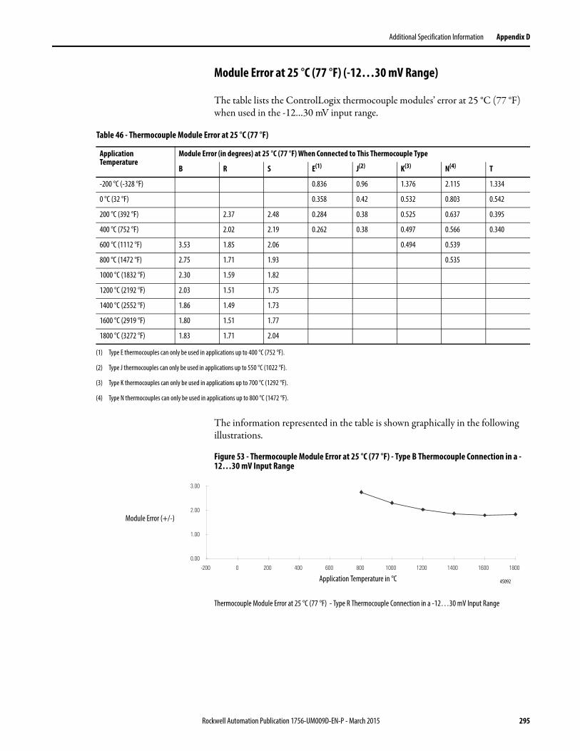
Additional Specification Information Appendix D
Module Error at 25 °C (77 °F) (-12…30 mV Range)
The table lists the ControlLogix thermocouple modules’ error at 25 °C (77 °F) when used in the -12…30 mV input range.
The information represented in the table is shown graphically in the following illustrations.
Figure 53 - Thermocouple Module Error at 25 °C (77 °F) - Type B Thermocouple Connection in a -12…30 mV Input Range
Thermocouple Module Error at 25 °C (77 °F) - Type R Thermocouple Connection in a -12…30 mV Input Range
Table 46 - Thermocouple Module Error at 25 °C (77 °F)
Application Temperature
Module Error (in degrees) at 25 °C (77 °F) When Connected to This Thermocouple Type
B R S E(1) J(2) K(3) N(4) T
-200 °C (-328 °F) 0.836 0.96 1.376 2.115 1.334
0 °C (32 °F) 0.358 0.42 0.532 0.803 0.542
200 °C (392 °F) 2.37 2.48 0.284 0.38 0.525 0.637 0.395
400 °C (752 °F) 2.02 2.19 0.262 0.38 0.497 0.566 0.340
600 °C (1112 °F) 3.53 1.85 2.06 0.494 0.539
800 °C (1472 °F) 2.75 1.71 1.93 0.535
1000 °C (1832 °F) 2.30 1.59 1.82
1200 °C (2192 °F) 2.03 1.51 1.75
1400 °C (2552 °F) 1.86 1.49 1.73
1600 °C (2919 °F) 1.80 1.51 1.77
1800 °C (3272 °F) 1.83 1.71 2.04
(1) Type E thermocouples can only be used in applications up to 400 °C (752 °F).
(2) Type J thermocouples can only be used in applications up to 550 °C (1022 °F).
(3) Type K thermocouples can only be used in applications up to 700 °C (1292 °F).
(4) Type N thermocouples can only be used in applications up to 800 °C (1472 °F).
Application Temperature in °C
0.00
1.00
2.00
3.00
-200 0 200 400 600 800 1000 1200 1400 1600 1800
Module Error (+/-)
45092
Rockwell Automation Publication 1756-UM009D-EN-P - March 2015 295
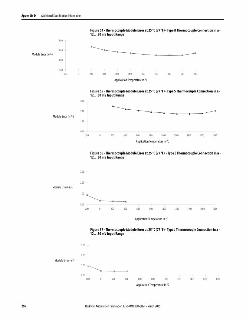
Appendix D Additional Specification Information
Figure 54 - Thermocouple Module Error at 25 °C (77 °F) - Type R Thermocouple Connection in a -12…30 mV Input Range
Figure 55 - Thermocouple Module Error at 25 °C (77 °F) - Type S Thermocouple Connection in a -12…30 mV Input Range
Figure 56 - Thermocouple Module Error at 25 °C (77 °F) - Type E Thermocouple Connection in a -12…30 mV Input Range
Figure 57 - Thermocouple Module Error at 25 °C (77 °F) - Type J Thermocouple Connection in a -12…30 mV Input Range
0.00
1.00
2.00
3.00
-200 0 200 400 600 800 1000 1200 1400 1600 1800
Application Temperature in °C
Module Error (+/-)
0.00
1.00
2.00
3.00
-200 0 200 400 600 800 1000 1200 1400 1600 1800
Application Temperature in °C
Module Error (+/-)
Application Temperature in °C
0.00
1.00
2.00
3.00
-200 0 200 400 600 800 1000 1200 1400 1600 1800
Module Error (+/-)
0.00
1.00
2.00
3.00
-200 0 200 400 600 800 1000 1200 1400 1600 1800
Application Temperature in °C
Module Error (+/-)
296 Rockwell Automation Publication 1756-UM009D-EN-P - March 2015
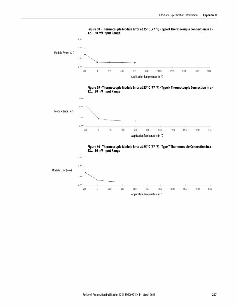
Additional Specification Information Appendix D
Figure 58 - Thermocouple Module Error at 25 °C (77 °F) - Type K Thermocouple Connection in a -12…30 mV Input Range
Figure 59 - Thermocouple Module Error at 25 °C (77 °F) - Type N Thermocouple Connection in a -12…30 mV Input Range
Figure 60 - Thermocouple Module Error at 25 °C (77 °F) - Type T Thermocouple Connection in a -12…30 mV Input Range
0.00
1.00
2.00
3.00
-200 0 200 400 600 800 1000 1200 1400 1600 1800
Module Error (+/-)
Application Temperature in °C
0.00
1.00
2.00
3.00
-200 0 200 400 600 800 1000 1200 1400 1600 1800
Module Error (+/-)
Application Temperature in °C
0.00
1.00
2.00
3.00
-200 0 200 400 600 800 1000 1200 1400 1600 1800
Module Error (+/-)
Application Temperature in °C
Rockwell Automation Publication 1756-UM009D-EN-P - March 2015 297
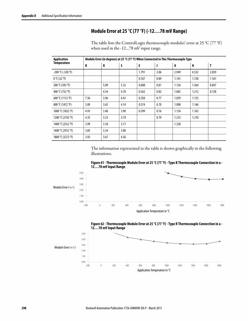
Appendix D Additional Specification Information
Module Error at 25 °C (77 °F) (-12…78 mV Range)
The table lists the ControlLogix thermocouple modules’ error at 25 °C (77 °F) when used in the -12…78 mV input range.
The information represented in the table is shown graphically in the following illustrations.
Figure 61 - Thermocouple Module Error at 25 °C (77 °F) - Type B Thermocouple Connection in a -12…78 mV Input Range
Figure 62 - Thermocouple Module Error at 25 °C (77 °F) - Type R Thermocouple Connection in a -12…78 mV Input Range
Application Temperature
Module Error (in degrees) at 25 °C (77 °F) When Connected to This Thermocouple Type
B R S E J K N T
-200 °C (-328 °F) 1.791 2.06 2.949 4.532 2.859
0 °C (32 °F) 0.767 0.89 1.141 1.720 1.161
200 °C (392 °F) 5.09 5.32 0.608 0.81 1.126 1.364 0.847
400 °C (752 °F) 4.34 4.70 0.562 0.82 1.065 1.212 0.728
600 °C (1112 °F) 7.56 3.96 4.41 0.558 0.77 1.059 1.155
800 °C (1472 °F) 5.89 3.65 4.14 0.574 0.70 1.098 1.146
1000 °C (1832 °F) 4.93 3.40 3.90 0.599 0.76 1.154 1.165
1200 °C (2192 °F) 4.35 3.23 3.74 0.79 1.233 1.210
1400 °C (2552 °F) 3.99 3.18 3.71 1.328
1600 °C (2912 °F) 3.85 3.24 3.80
1800 °C (3272 °F) 3.92 3.67 4.36
0.00
1.00
2.00
3.00
4.00
5.00
-200 0 200 400 600 800 1000 1200 1400 1600 1800
Module Error (+/-)
Application Temperature in °C
0.00
1.00
2.00
3.00
4.00
5.00
-200 0 200 400 600 800 1000 1200 1400 1600 1800
Module Error (+/-)
Application Temperature in °C
298 Rockwell Automation Publication 1756-UM009D-EN-P - March 2015
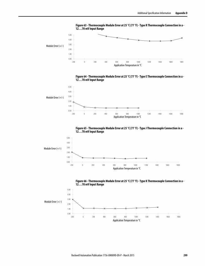
Additional Specification Information Appendix D
Figure 63 - Thermocouple Module Error at 25 °C (77 °F) - Type R Thermocouple Connection in a -12…78 mV Input Range
Figure 64 - Thermocouple Module Error at 25 °C (77 °F) - Type E Thermocouple Connection in a -12…78 mV Input Range
Figure 65 - Thermocouple Module Error at 25 °C (77 °F) - Type J Thermocouple Connection in a -12…78 mV Input Range
Figure 66 - Thermocouple Module Error at 25 °C (77 °F) - Type K Thermocouple Connection in a -12…78 mV Input Range
0.00
1.00
2.00
3.00
4.00
5.00
-200 0 200 400 600 800 1000 1200 1400 1600 1800
Module Error (+/-)
Application Temperature in °C
0.00
1.00
2.00
3.00
4.00
5.00
-200 0 200 400 600 800 1000 1200 1400 1600 1800
Module Error (+/-)
Application Temperature in °C
0.00
1.00
2.00
3.00
4.00
5.00
-200 0 200 400 600 800 1000 1200 1400 1600 1800
Application Temperature in °C
Module Error (+/-)
0.00
1.00
2.00
3.00
4.00
5.00
-200 0 200 400 600 800 1000 1200 1400 1600 1800
Application Temperature in °C
Module Error (+/-)
Rockwell Automation Publication 1756-UM009D-EN-P - March 2015 299
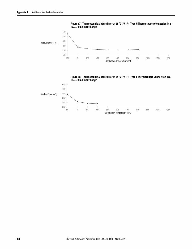
Appendix D Additional Specification Information
Figure 67 - Thermocouple Module Error at 25 °C (77 °F) - Type N Thermocouple Connection in a -12…78 mV Input Range
Figure 68 - Thermocouple Module Error at 25 °C (77 °F) - Type T Thermocouple Connection in a -12…78 mV Input Range
0.00
1.00
2.00
3.00
4.00
5.00
-200 0 200 400 600 800 1000 1200 1400 1600 1800
Application Temperature in °C
Module Error (+/-)
0.00
1.00
2.00
3.00
4.00
5.00
-200 0 200 400 600 800 1000 1200 1400 1600 1800
Application Temperature in °C
Module Error (+/-)
300 Rockwell Automation Publication 1756-UM009D-EN-P - March 2015
Additional Specification Information Appendix D
Thermocouple Resolution Thermocouple resolution indicates the degrees that an application temperature must change before the ControlLogix thermocouple module reports a change. Resolution varies depending on the these factors.
• Input range used, either:– -12…30 mV– -12…78 mV
• Thermocouple type, any of the following:– B, R, S, E, J, K, N, T, L and D (L and D are used on the
1756-IT6I2 module only)• Application temperature that is, the temperature of the physical location
where the thermocouple is being used)
EXAMPLE For example, when the 1756-IT6I module is operating in the following conditions:
• -12…30 mV input range• connected to a type K thermocouple• application temperature of 400 °C (752 °F)
the resolution is 0.017 degrees.
In other words, the application temperature must change by 0.017 degrees or greater for the 1756-IT6I module to record a change. If the temperature stays in a range from 399.984…400.0169 °C (751.971…752.030 °F), the module continues to report an application temperatureof 400 °C (752 °F).
Rockwell Automation Publication 1756-UM009D-EN-P - March 2015 301

Appendix D Additional Specification Information
Module Resolution (-12…30 mV Range)
The table lists the resolution of ControlLogix thermocouple modules when used in the -12…30 mV input range.
The information represented in the table is shown graphically in the following illustrations.
Figure 69 - Thermocouple Module Resolution - Type B Thermocouple Connection in a -12…30 mV Input Range
Application Temperature
Module Resolution (in degrees) When Connected to This Thermocouple Type
B R S E(1) J(2) K(3) N(4) T
-200 °C (-328 °F) 0.028 0.032 0.046 0.071 0.044
0 °C (32 °F) 0.13 0.13 0.012 0.014 0.018 0.027 0.018
200 °C (392 °F) 0.08 0.08 0.009 0.013 0.018 0.021 0.013
400 °C (752 °F) 0.17 0.07 0.07 0.009 0.013 0.017 0.019 0.011
600 °C (1112 °F) 0.12 0.06 0.07 0.016 0.02
800 °C (1472 °F) 0.09 0.06 0.06 0.02
1000 °C (1832 °F) 0.08 0.05 0.06
1200 °C (2192 °F) 0.07 0.05 0.06
1400 °C (2552 °F) 0.06 0.05 0.06
1600 °C (2919 °F) 0.06 0.05 0.06
1800 °C (3272 °F) 0.06 0.06 0.07
(1) Type E thermocouples can only be used in applications up to 400 °C (752 °F).
(2) Type J thermocouples can only be used in applications up to 550 °C (1022 °F).
(3) Type K thermocouples can only be used in applications up to 700 °C (1292 °F).
(4) Type N thermocouples can only be used in applications up to 800 °C (1472 °F).
Application Temperature in °C
0.00
0.02
0.04
0.06
0.08
0.10
0.12
0.14
0.16
0.18
0.20
-200 0 200 400 600 800 1000 1200 1400 1600 1800
Minimum Amount of Degree Change Required for Thermocouple Module to Report the Change
302 Rockwell Automation Publication 1756-UM009D-EN-P - March 2015
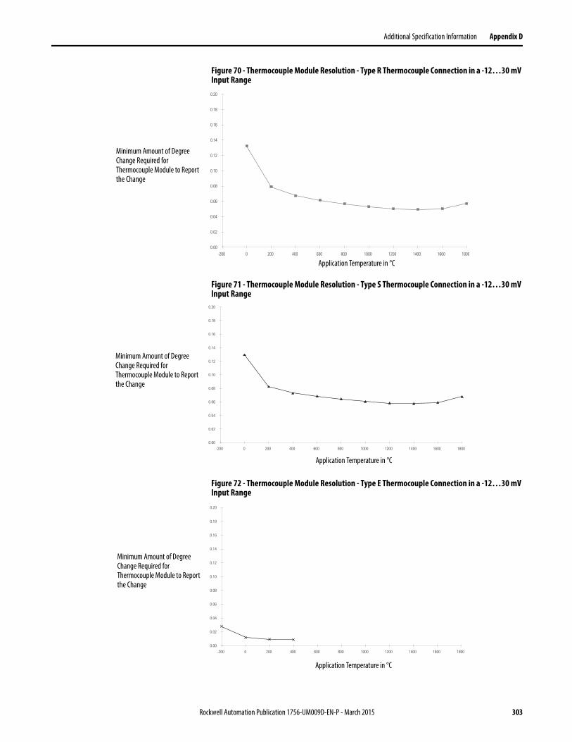
Additional Specification Information Appendix D
Figure 70 - Thermocouple Module Resolution - Type R Thermocouple Connection in a -12…30 mV Input Range
Figure 71 - Thermocouple Module Resolution - Type S Thermocouple Connection in a -12…30 mV Input Range
Figure 72 - Thermocouple Module Resolution - Type E Thermocouple Connection in a -12…30 mV Input Range
Application Temperature in °C
0.00
0.02
0.04
0.06
0.08
0.10
0.12
0.14
0.16
0.18
0.20
-200 0 200 400 600 800 1000 1200 1400 1600 1800
Minimum Amount of Degree Change Required for Thermocouple Module to Report the Change
Application Temperature in °C
0.00
0.02
0.04
0.06
0.08
0.10
0.12
0.14
0.16
0.18
0.20
-200 0 200 400 600 800 1000 1200 1400 1600 1800
Minimum Amount of Degree Change Required for Thermocouple Module to Report the Change
Application Temperature in °C
0.00
0.02
0.04
0.06
0.08
0.10
0.12
0.14
0.16
0.18
0.20
-200 0 200 400 600 800 1000 1200 1400 1600 1800
Minimum Amount of Degree Change Required for Thermocouple Module to Report the Change
Rockwell Automation Publication 1756-UM009D-EN-P - March 2015 303
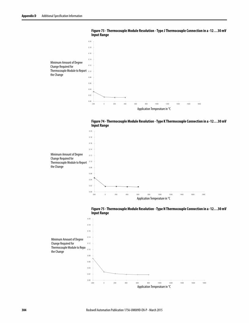
Appendix D Additional Specification Information
Figure 73 - Thermocouple Module Resolution - Type J Thermocouple Connection in a -12…30 mV Input Range
Figure 74 - Thermocouple Module Resolution - Type K Thermocouple Connection in a -12…30 mV Input Range
Figure 75 - Thermocouple Module Resolution - Type N Thermocouple Connection in a -12…30 mV Input Range
Application Temperature in °C
0.00
0.02
0.04
0.06
0.08
0.10
0.12
0.14
0.16
0.18
0.20
-200 0 200 400 600 800 1000 1200 1400 1600 1800
Minimum Amount of Degree Change Required for Thermocouple Module to Report the Change
Application Temperature in °C
Minimum Amount of Degree Change Required for Thermocouple Module to Report the Change
0.00
0.02
0.04
0.06
0.08
0.10
0.12
0.14
0.16
0.18
0.20
-200 0 200 400 600 800 1000 1200 1400 1600 1800
Minimum Amount of Degree Change Required for Thermocouple Module to Report the Change
Application Temperature in °C
0.00
0.02
0.04
0.06
0.08
0.10
0.12
0.14
0.16
0.18
0.20
-200 0 200 400 600 800 1000 1200 1400 1600 1800
304 Rockwell Automation Publication 1756-UM009D-EN-P - March 2015
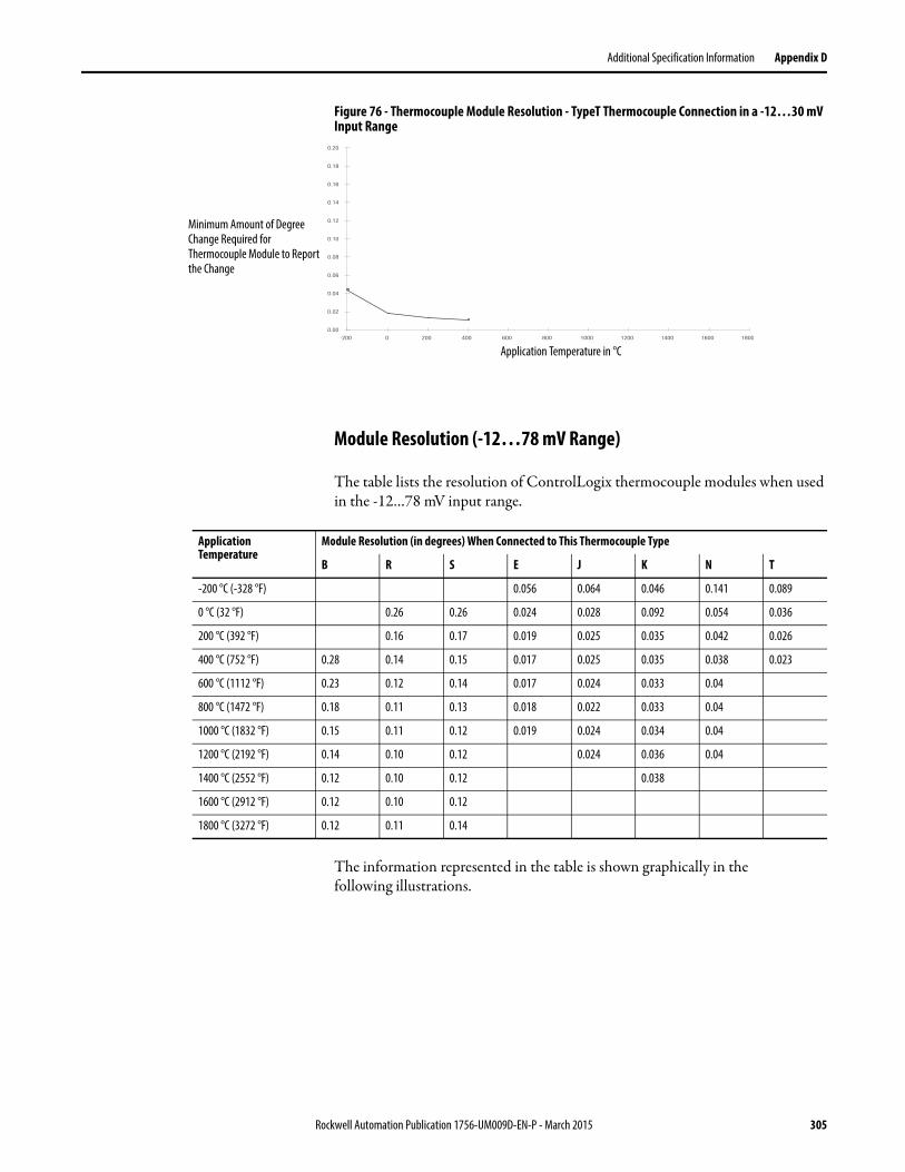
Additional Specification Information Appendix D
Figure 76 - Thermocouple Module Resolution - TypeT Thermocouple Connection in a -12…30 mV Input Range
Module Resolution (-12…78 mV Range)
The table lists the resolution of ControlLogix thermocouple modules when used in the -12…78 mV input range.
The information represented in the table is shown graphically in thefollowing illustrations.
0.00
0.02
0.04
0.06
0.08
0.10
0.12
0.14
0.16
0.18
0.20
-200 0 200 400 600 800 1000 1200 1400 1600 1800
Minimum Amount of Degree Change Required for Thermocouple Module to Report the Change
Application Temperature in °C
Application Temperature
Module Resolution (in degrees) When Connected to This Thermocouple Type
B R S E J K N T
-200 °C (-328 °F) 0.056 0.064 0.046 0.141 0.089
0 °C (32 °F) 0.26 0.26 0.024 0.028 0.092 0.054 0.036
200 °C (392 °F) 0.16 0.17 0.019 0.025 0.035 0.042 0.026
400 °C (752 °F) 0.28 0.14 0.15 0.017 0.025 0.035 0.038 0.023
600 °C (1112 °F) 0.23 0.12 0.14 0.017 0.024 0.033 0.04
800 °C (1472 °F) 0.18 0.11 0.13 0.018 0.022 0.033 0.04
1000 °C (1832 °F) 0.15 0.11 0.12 0.019 0.024 0.034 0.04
1200 °C (2192 °F) 0.14 0.10 0.12 0.024 0.036 0.04
1400 °C (2552 °F) 0.12 0.10 0.12 0.038
1600 °C (2912 °F) 0.12 0.10 0.12
1800 °C (3272 °F) 0.12 0.11 0.14
Rockwell Automation Publication 1756-UM009D-EN-P - March 2015 305
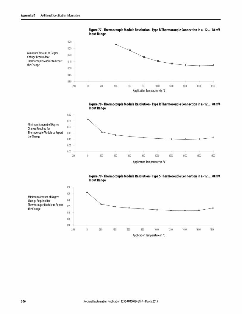
Appendix D Additional Specification Information
Figure 77 - Thermocouple Module Resolution - Type B Thermocouple Connection in a -12…78 mV Input Range
Figure 78 - Thermocouple Module Resolution - Type R Thermocouple Connection in a -12…78 mV Input Range
Figure 79 - Thermocouple Module Resolution - Type S Thermocouple Connection in a -12…78 mV Input Range
Minimum Amount of Degree Change Required for Thermocouple Module to Report the Change
0.00
0.05
0.10
0.15
0.20
0.25
0.30
-200 0 200 400 600 800 1000 1200 1400 1600 1800
Application Temperature in °C
Minimum Amount of Degree Change Required for Thermocouple Module to Report the Change
0.00
0.05
0.10
0.15
0.20
0.25
0.30
-200 0 200 400 600 800 1000 1200 1400 1600 1800
Application Temperature in °C
Minimum Amount of Degree Change Required for Thermocouple Module to Report the Change
0.00
0.05
0.10
0.15
0.20
0.25
0.30
-200 0 200 400 600 800 1000 1200 1400 1600 1800
Application Temperature in °C
306 Rockwell Automation Publication 1756-UM009D-EN-P - March 2015
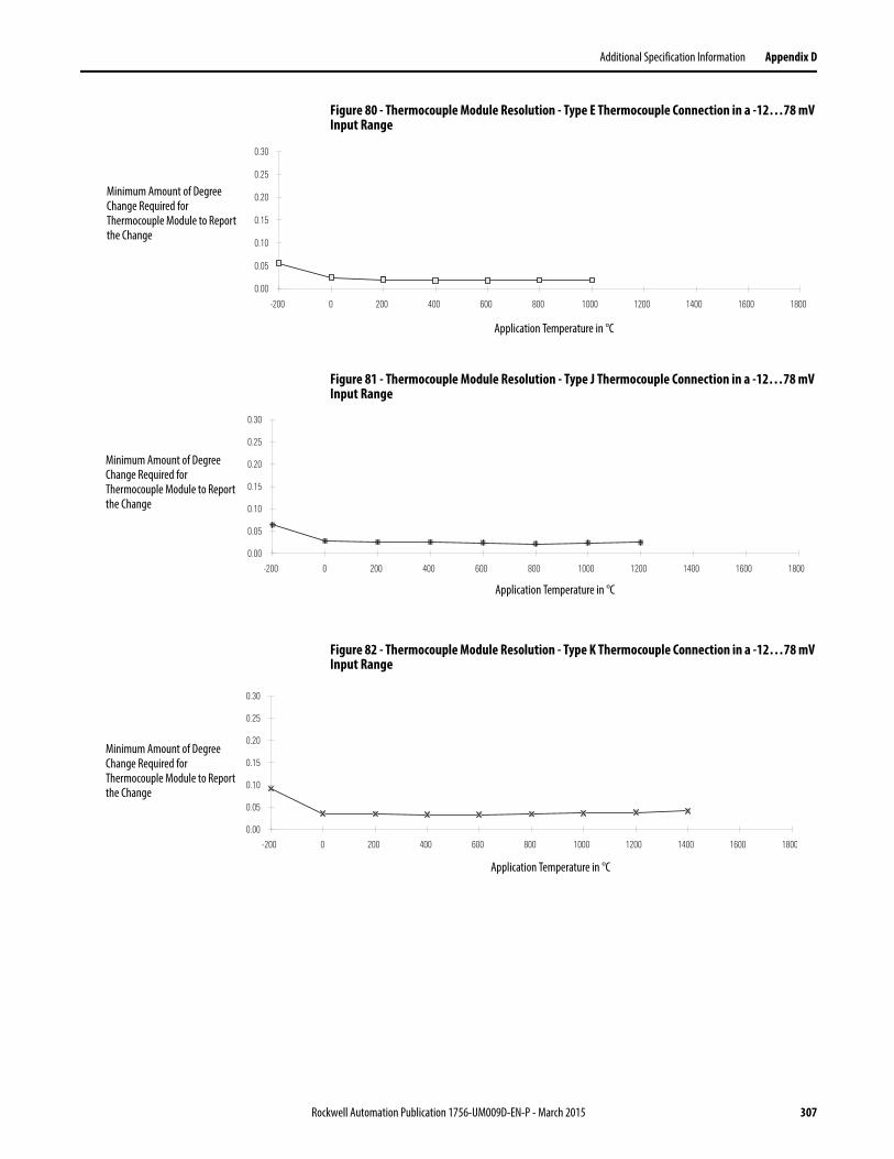
Additional Specification Information Appendix D
Figure 80 - Thermocouple Module Resolution - Type E Thermocouple Connection in a -12…78 mV Input Range
Figure 81 - Thermocouple Module Resolution - Type J Thermocouple Connection in a -12…78 mV Input Range
Figure 82 - Thermocouple Module Resolution - Type K Thermocouple Connection in a -12…78 mV Input Range
Minimum Amount of Degree Change Required for Thermocouple Module to Report the Change
0.00
0.05
0.10
0.15
0.20
0.25
0.30
-200 0 200 400 600 800 1000 1200 1400 1600 1800
Application Temperature in °C
Minimum Amount of Degree Change Required for Thermocouple Module to Report the Change
0.00
0.05
0.10
0.15
0.20
0.25
0.30
-200 0 200 400 600 800 1000 1200 1400 1600 1800
Application Temperature in °C
Minimum Amount of Degree Change Required for Thermocouple Module to Report the Change
Application Temperature in °C
0.00
0.05
0.10
0.15
0.20
0.25
0.30
-200 0 200 400 600 800 1000 1200 1400 1600 1800
Application Temperature in °C
Rockwell Automation Publication 1756-UM009D-EN-P - March 2015 307
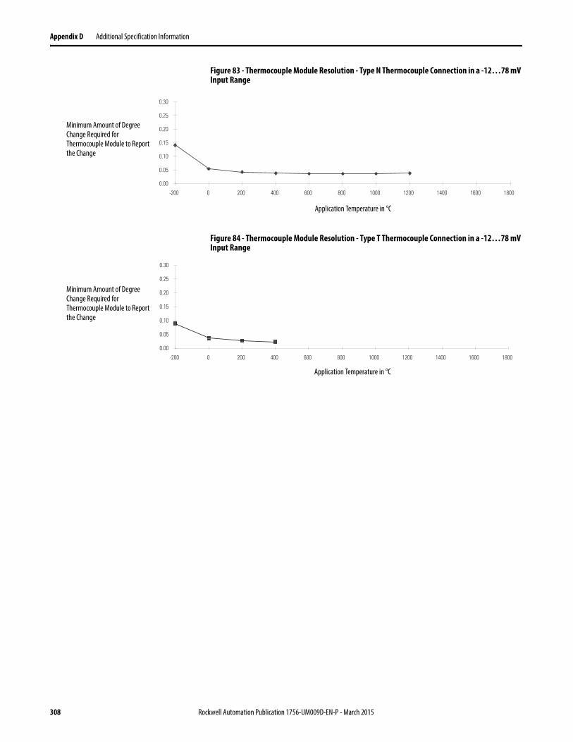
Appendix D Additional Specification Information
Figure 83 - Thermocouple Module Resolution - Type N Thermocouple Connection in a -12…78 mV Input Range
Figure 84 - Thermocouple Module Resolution - Type T Thermocouple Connection in a -12…78 mV Input Range
Minimum Amount of Degree Change Required for Thermocouple Module to Report the Change
0.00
0.05
0.10
0.15
0.20
0.25
0.30
-200 0 200 400 600 800 1000 1200 1400 1600 1800
Application Temperature in °C
Minimum Amount of Degree Change Required for Thermocouple Module to Report the Change
0.00
0.05
0.10
0.15
0.20
0.25
0.30
-200 0 200 400 600 800 1000 1200 1400 1600 1800
Application Temperature in °C
308 Rockwell Automation Publication 1756-UM009D-EN-P - March 2015
Additional Specification Information Appendix D
How to Deal with Incorrect Thermocouple Temperature Readings
The first thought when an incorrect temperature reading is reported back in a thermocouple input module is that the module is out of calibration. This is typically not the case, particularly if the module has just been installed out-of-the-box.
All thermocouple input modules are shipped factory calibrated so it is unlikely that they would need to be calibrated on installation.
To determine the cause of the incorrect reading, the nature of the incorrect reading must be discerned first. The module:
1. Always reads maximum.
2. Always reads minimum.
3. Reads erratic (data jumping around).
4. Reads with an offset over the entire range.
In general, if incorrect readings appear on a new install then checking for proper installation and configuration would typically prevail as a cause versus an existing working module where a hardware failure of some type (channel or module) would be more likely the cause.
Also, if more than one channel is experiencing these symptoms, disconnect all thermocouples except one. This can help determine if it is external hardware or the module itself is the cause.
Before attempting to troubleshoot these symptoms, a great deal of work can be saved by first, visually inspecting the module, and second, applying a thermocouple emulator directly to the module input in question. Make sure the module is powered and communicating based on the status indicators. Red or flashing green status indicators signify a problem.
Make sure wiring is intact and correct and the cold junction sensors (CJS) are installed correctly for the correct wiring arm, terminal base, or removable terminal block. If all looks correct, then remove the thermocouple from the channel in question and apply the emulator.
The emulator is designed to provide a voltage at the terminals equivalent to the voltage expected for the thermocouple type it is emulating. If the temperature reports back correctly then the module is performing as expected and the thermocouple and wiring are suspect. If the emulator temperature is not reporting back correctly, then the module hardware, configuration, or the software application are suspect.
We highly recommend using a thermocouple emulator for initial troubleshooting. In lieu of an emulator, a millivolt signal can be applied to the input. To make this work, the module would have to be reconfigured to read a
Rockwell Automation Publication 1756-UM009D-EN-P - March 2015 309
Appendix D Additional Specification Information
millivolt signal. If the module is reading back the millivolt correctly, then the module is performing as expected.
Troubleshooting Checklist
Check for these symptoms when troubleshooting a module.
1. Thermocouple reading maximum (upscale) usually means that there is an open circuit. Thermocouple modules provide open-circuit detection and the data reports back upscale when an open circuit is detected. Check the wiring, terminations, and for an open thermocouple. Make sure the length of the thermocouple cable is within module specifications, where too long a length, thus a higher impedance, could be interpreted as an open circuit. See page 118 for more information.
2. Thermocouple reading minimum (downscale) usually means that there is a short-circuited input. Check wiring and correct terminations.
3. Erratic readings (data jumping around) are a symptom of noise. The magnitude of noise can be seen with an oscilloscope. Disconnect all but one thermocouple to see if other channels are affecting each other (bleed-over). The effect of noise can be eliminated or reduced by removing or suppressing the source of the noise or by employing the hardware and or software filters provided by the thermocouple module.
4. Offset readings can be caused by a DC signal riding on top of the thermocouple signal. The magnitude of the offset can be seen with an oscilloscope. Again, by disconnecting all but one thermocouple, one can see if other channels are affecting each other (bleed-over).
5. Make sure the module is not in calibration mode. This is module dependant, but in general, specific bits have to be turned on toenable calibration.
The 1756-IT6I Thermocouple module, when configured with all channels for the same configuration and measuring the same (ambient) temperature, has a temperature reading difference between upper and lower channels up to -13.33…-12.22 °C (8…10 °F). To improve the accuracy of the module’s reading, we recommend that you select remote CJ compensation and wireto a 1492-AIFM6TC-3.
Offset readings can also be seen if the CJS is defective or not installed properly. When, provided, check the module input data for a CJS defective diagnostic bit. Thermocouples also report back ambient temperature and provide an accurate ambient temperature if the CJS is healthy, wired properly, and the module is operating within specifications.
310 Rockwell Automation Publication 1756-UM009D-EN-P - March 2015
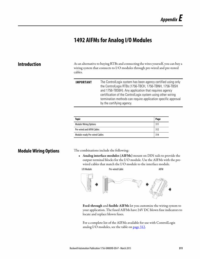
Appendix E
1492 AIFMs for Analog I/O Modules
Introduction As an alternative to buying RTBs and connecting the wires yourself, you can buy a wiring system that connects to I/O modules through pre-wired and pre-tested cables.
Module Wiring Options The combinations include the following:• Analog interface modules (AIFMs) mount on DIN rails to provide the
output terminal blocks for the I/O module. Use the AIFMs with the pre-wired cables that match the I/O module to the interface module.
Feed-through and fusible AIFMs let you customize the wiring system to your application. The fused AIFMs have 24V DC blown fuse indicators to locate and replace blown fuses.
For a complete list of the AIFMs available for use with ControlLogix analog I/O modules, see the table on page 312.
IMPORTANT The ControlLogix system has been agency certified using only the ControlLogix RTBs (1756-TBCH, 1756-TBNH, 1756-TBSH and 1756-TBS6H). Any application that requires agency certification of the ControlLogix system using other wiring termination methods can require application specific approval by the certifying agency.
Topic Page
Module Wiring Options 311
Pre-wired and AIFM Cables 312
Module-ready Pre-wired Cables 314
I/O Module Pre-wired Cable AIFM
Rockwell Automation Publication 1756-UM009D-EN-P - March 2015 311
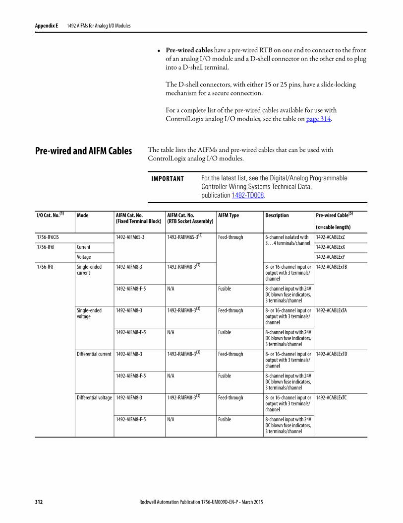
Appendix E 1492 AIFMs for Analog I/O Modules
• Pre-wired cables have a pre-wired RTB on one end to connect to the front of an analog I/O module and a D-shell connector on the other end to plug into a D-shell terminal.
The D-shell connectors, with either 15 or 25 pins, have a slide-locking mechanism for a secure connection.
For a complete list of the pre-wired cables available for use with ControlLogix analog I/O modules, see the table on page 314.
Pre-wired and AIFM Cables The table lists the AIFMs and pre-wired cables that can be used with ControlLogix analog I/O modules.
IMPORTANT For the latest list, see the Digital/Analog Programmable Controller Wiring Systems Technical Data,publication 1492-TD008.
I/O Cat. No.(1) Mode AIFM Cat. No.(Fixed Terminal Block)
AIFM Cat. No. (RTB Socket Assembly)
AIFM Type Description Pre-wired Cable(5)
(x=cable length)
1756-IF6CIS 1492-AIFM6S-3 1492-RAIFM6S-3(2) Feed-through 6-channel isolated with 3…4 terminals/channel
1492-ACABLExZ
1756-IF6I Current 1492-ACABLExX
Voltage 1492-ACABLExY
1756-IF8 Single-ended current
1492-AIFM8-3 1492-RAIFM8-3(3) 8- or 16-channel input or output with 3 terminals/channel
1492-ACABLExTB
1492-AIFM8-F-5 N/A Fusible 8-channel input with 24V DC blown fuse indicators, 3 terminals/channel
Single-ended voltage
1492-AIFM8-3 1492-RAIFM8-3(3) Feed-through 8- or 16-channel input or output with 3 terminals/channel
1492-ACABLExTA
1492-AIFM8-F-5 N/A Fusible 8-channel input with 24V DC blown fuse indicators, 3 terminals/channel
Differential current 1492-AIFM8-3 1492-RAIFM8-3(3) Feed-through 8- or 16-channel input or output with 3 terminals/channel
1492-ACABLExTD
1492-AIFM8-F-5 N/A Fusible 8-channel input with 24V DC blown fuse indicators, 3 terminals/channel
Differential voltage 1492-AIFM8-3 1492-RAIFM8-3(3) Feed-through 8- or 16-channel input or output with 3 terminals/channel
1492-ACABLExTC
1492-AIFM8-F-5 N/A Fusible 8-channel input with 24V DC blown fuse indicators, 3 terminals/channel
312 Rockwell Automation Publication 1756-UM009D-EN-P - March 2015
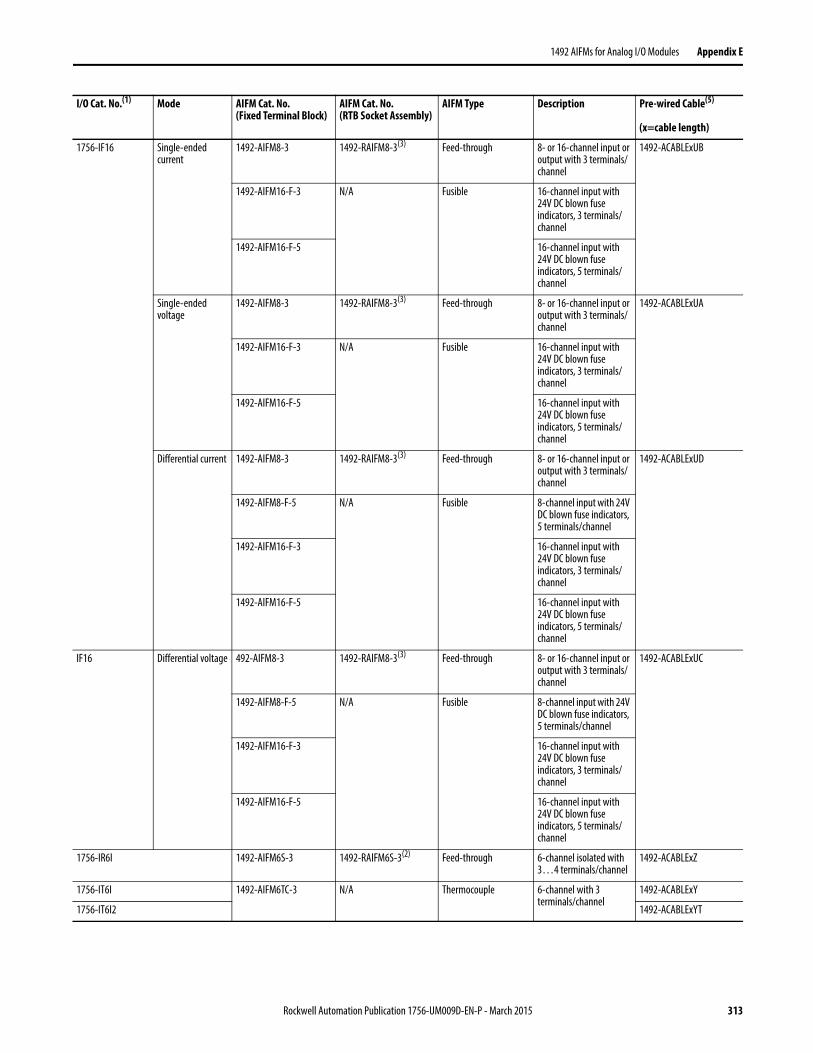
1492 AIFMs for Analog I/O Modules Appendix E
1756-IF16 Single-ended current
1492-AIFM8-3 1492-RAIFM8-3(3) Feed-through 8- or 16-channel input or output with 3 terminals/channel
1492-ACABLExUB
1492-AIFM16-F-3 N/A Fusible 16-channel input with 24V DC blown fuse indicators, 3 terminals/channel
1492-AIFM16-F-5 16-channel input with 24V DC blown fuse indicators, 5 terminals/channel
Single-ended voltage
1492-AIFM8-3 1492-RAIFM8-3(3) Feed-through 8- or 16-channel input or output with 3 terminals/channel
1492-ACABLExUA
1492-AIFM16-F-3 N/A Fusible 16-channel input with 24V DC blown fuse indicators, 3 terminals/channel
1492-AIFM16-F-5 16-channel input with 24V DC blown fuse indicators, 5 terminals/channel
Differential current 1492-AIFM8-3 1492-RAIFM8-3(3) Feed-through 8- or 16-channel input or output with 3 terminals/channel
1492-ACABLExUD
1492-AIFM8-F-5 N/A Fusible 8-channel input with 24V DC blown fuse indicators, 5 terminals/channel
1492-AIFM16-F-3 16-channel input with 24V DC blown fuse indicators, 3 terminals/channel
1492-AIFM16-F-5 16-channel input with 24V DC blown fuse indicators, 5 terminals/channel
IF16 Differential voltage 492-AIFM8-3 1492-RAIFM8-3(3) Feed-through 8- or 16-channel input or output with 3 terminals/channel
1492-ACABLExUC
1492-AIFM8-F-5 N/A Fusible 8-channel input with 24V DC blown fuse indicators, 5 terminals/channel
1492-AIFM16-F-3 16-channel input with 24V DC blown fuse indicators, 3 terminals/channel
1492-AIFM16-F-5 16-channel input with 24V DC blown fuse indicators, 5 terminals/channel
1756-IR6I 1492-AIFM6S-3 1492-RAIFM6S-3(2) Feed-through 6-channel isolated with 3…4 terminals/channel
1492-ACABLExZ
1756-IT6I 1492-AIFM6TC-3 N/A Thermocouple 6-channel with 3 terminals/channel
1492-ACABLExY
1756-IT6I2 1492-ACABLExYT
I/O Cat. No.(1) Mode AIFM Cat. No.(Fixed Terminal Block)
AIFM Cat. No. (RTB Socket Assembly)
AIFM Type Description Pre-wired Cable(5)
(x=cable length)
Rockwell Automation Publication 1756-UM009D-EN-P - March 2015 313
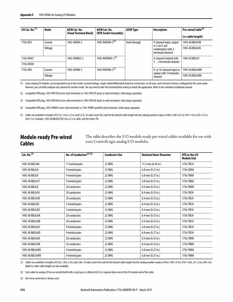
Appendix E 1492 AIFMs for Analog I/O Modules
Module-ready Pre-wired Cables
The table describes the I/O module-ready pre-wired cables available for use with your ControlLogix analog I/O modules.
1756-OF4 Current 1492-AIFM4-3 1492-RAIFM4-3(4) Feed-through 4-channel input, output or 2-in/2-out combination with 3 terminals/channel
1492-ACABLExVB
Voltage 1492-ACABLExVA
1756-OF6CI 1492-AIFM6S-3 1492-RAIFM6S-3(2) 6-channel isolated with 3…4 terminals/channel
1492-ACABLExY
1756-OF6VI
1756-OF8 Current 1492-AIFM8-3 1492-RAIFM8-3(3) 8- or 16-channel input or output with 3 terminals/channel
1492-ACABLExWB
Voltage 1492-ACABLExWA
(1) Some analog I/O modules can be operated in up to four modes (current/voltage, single-ended/differential) based on connections. In all cases, each channel is factory-configured for the same mode. However, you can field configure any channel for another mode. You nay need to alter the terminal block wiring to match the application. Refer to the controller installation manual.
(2) Compatible RTB plug; 1492-RTB12N (screw-style terminals) or 1492-RTB12P (push-in style terminals). Order plugs separately.
(3) Compatible RTB plug; 1492-RTB16N (screw-style terminals) or 1492-RTB16P (push-in style terminals). Order plugs separately
(4) Compatible RTB plug; 1492-RTB8N (screw-style terminals) or 1492-RTB8P (push0in style terminals). Order plugs separately.
(5) Cables are available in lengths of 0.5 m, 1.0 m, 2.5 m, and 5.0 m. To order, insert the code for the desired cable length into the catalog number in place of the x: 005=0.5 m, 010=1.0 m, 025=2.5 m, 050=5 m. Example: 1492-ACABLE025TB is for a 2.5 m cable, and the letters TB.
I/O Cat. No.(1) Mode AIFM Cat. No.(Fixed Terminal Block)
AIFM Cat. No. (RTB Socket Assembly)
AIFM Type Description Pre-wired Cable(5)
(x=cable length)
Cat. No.(1) No. of Conductors(2) (3) Conductor Size Nominal Outer Diameter RTB at the I/O Module End
1492-ACABLExM 11 twisted pairs 22 AWG 11.5 mm (0.45 in.) 1756-TBCH
1492-ACABLExX 9 twisted pairs 22 AWG 6.8 mm (0.27 in.) 1756-TBNH
1492-ACABLExY 9 twisted pairs 22 AWG 6.8 mm (0.27 in.) 1756-TBNH
1492-ACABLExYT 9 twisted pairs 22 AWG 6.8 mm (0.27 in.) 1756-TBNH
1492-ACABLExZ 20 conductors 22 AWG 8.4 mm (0.33 in.) 1756-TBNH
1492-ACABLExTA 20 conductors 22 AWG 8.4 mm (0.33 in.) 1756-TBCH
1492-ACABLExTB 20 conductors 22 AWG 8.4 mm (0.33 in.) 1756-TBCH
1492-ACABLExTC 5 twisted pairs 22 AWG 8.4 mm (0.33 in.) 1756-TBCH
1492-ACABLExTD 5 twisted pairs 22 AWG 8.4 mm (0.33 in.) 1756-TBCH
1492-ACABLExUA 20 conductors 22 AWG 8.4 mm (0.33 in.) 1756-TBCH
1492-ACABLExUB 20 conductors 22 AWG 8.4 mm (0.33 in.) 1756-TBCH
1492-ACABLExUC 9 twisted pairs 22 AWG 6.8 mm (0.27 in.) 1756-TBCH
1492-ACABLExUD 9 twisted pairs 22 AWG 6.8 mm (0.27 in.) 1756-TBCH
1492-ACABLExVA 20 conductors 22 AWG 8.4 mm (0.33 in.) 1756-TBNH
1492-ACABLExVB 20 conductors 22 AWG 8.4 mm (0.33 in.) 1756-TBNH
1492-ACABLExWA 9 twisted pairs 22 AWG 6.8 mm (0.27 in.) 1756-TBNH
1492-ACABLExWB 9 twisted pairs 22 AWG 6.8 mm (0.27 in.) 1756-TBNH
(1) Cables are available in lengths of 0.5m, 1.0m, 2.5m, and 5.0m. To order, insert the code for the desired cable length into the catalog number in place of the x: 005=0.5m, 010=1.0m, 25=2.5m, 050=5m. Build-to-order cable lengths are also available.
(2) Each cable for analog I/O has an overall shield with a ring lug on a 200mm (8.87 in.) exposed drain wire at the I/O module end of the cable.
(3) Not every connection is always used.
314 Rockwell Automation Publication 1756-UM009D-EN-P - March 2015
Glossary
analog interface module (AIFM)
Modules connect to pre-wired cables to provide the output terminal blocks for the analog I/O module. These modules can be mounted on a DIN rail.
broadcast
Data transmissions to all addresses or functions.
communication format
Format that defines the type of information transferred between an I/O module and its owner-controller. This format also defines the tags created for each I/O module.
compatible match
An electronic keying protection mode that requires that the physical module and the module configured in the software to match according to vendor and catalog number. In this case, the minor revision of the module must begreater than or equal to that of the configured slot.
connection
The communication mechanism from the controller to another module in the control system.
coordinated system time (CST)
Timer value that is kept synchronized for all modules within a single ControlBus chassis.
direct connection
An I/O connection where the controller establishes an individual connection with I/O modules.
disable keying
An electronic keying protection mode that requires no attributes of the physical module and the module configured in the software to match.
download
The process of transferring the contents of a project on the workstation into the controller.
Publication 1756-UM009D-EN-P - March 2015 315
Glossary
electronic keying
A feature where modules can be requested to perform an electronic check to make sure that the physical module is consistent with what was configured by the software.
exact match
An electronic keying protection mode that requires the physical module and the module configured in the software to match according to vendor, catalog number, major revision and minor revision.
field side
Interface between user field wiring and I/O module.
inhibit
A ControlLogix process that lets you configure an I/O module but prevent it from communicating with the owner-controller. In this case, the controller behaves as if the I/O module does not exist at all.
interface module (IFM)
A module that uses pre-wired cable to connect wiring to an I/O module.
listen-only connection
An I/O connection where another controller owns/provides the configuration and data for the module.
major revision
A module revision that is updated any time there is a functional changeto the module.
minor revision
A module revision that is updated any time there is a change to the module that does not affect its function or interface.
multicast
Data transmissions that reach a specific group of one or more destinations.
multiple owners
A configuration set-up where multiple owner-controllers use exactly the same configuration information to simultaneously own an input module.
316 Publication 1756-UM009D-EN-P - March 2015
Glossary
network update time (NUT)
The smallest repetitive time interval in which the data can be sent on a ControlNet network. The NUT ranges from 2 ms to 100 ms.
owner-controller
The controller that creates and stores the primary configuration and communication connection to a module.
Program mode
In this mode the following events occur:
• Controller program is not executing.
• Inputs are still actively producing data.
• Outputs are not actively controlled and go to their configuredProgram mode.
rack connection
An I/O connection where the 1756-CNB module collects digital I/O words into a rack image to conserve ControlNet connections and bandwidth.
rack optimization
A communication format in which the 1756-CNB module collects all digital I/O words in the remote chassis and sends them to controller as a single rack image.
remote connection
An I/O connection where the controller establishes an individual connection with I/O modules in a remote chassis.
removal and insertion under power (RIUP)
ControlLogix feature that allows a user to install or remove a module or RTB while power is applied.
removable terminal block (RTB)
Field wiring connector for I/O modules.
requested packet interval (RPI)
The maximum amount of time between broadcasts of I/O data.
Publication 1756-UM009D-EN-P - March 2015 317
Glossary
Run mode
In this mode, the following events occur:
• Controller program is executing
• Inputs are actively producing data
• Outputs are actively controlled
service
A system feature that is performed on user demand, such as fuse reset or diagnostic latch reset.
system side
Backplane side of the interface to the I/O module.
tag
A named area of the controller’s memory where data is stored.
timestamping
A ControlLogix process that stamps a change in input data with a relative time reference of when that change occurred.
318 Publication 1756-UM009D-EN-P - March 2015
Index
Numerics10 Ohm offset
1756-IR6I, 1756-IT6I and 1756-IT6I2 modules 114
1756-TBCH cage clamp RTB 1761756-TBE extended housing 1781756-TBS6H spring clamp RTB 177
Aagency
certification 16alarm deadband 55, 90, 113alarms
latching 38limit alarm 139, 156process alarm 54, 89, 112rate alarm 55, 90, 114
analog I/O 15
Ccage clamp
wiring the RTB 176calibration
1756-IF16 and 1756-IF8 modules 2151756-IF6CIS and 1756-IF6I modules 2211756-IR6I module 2271756-IT6I and 1756-IT6I2 modules 232using RSLogix 5000 213
certificationagency 16
channel fault word1756-IF16 module 69
floating point mode 70, 71integer mode 73, 74
1756-IF6CIS and 1756-IF6I modules 100floating point mode 101, 102, 104integer mode 105
1756-IF8 module 76floating point mode 77, 78integer mode 80
1756-IR6I, 1756-IT6I and 1756-IT6I2 modules 128
floating point mode 129, 130integer mode 132, 133
1756-OF4 and 1756-OF8 modules 145floating point mode 146, 147integer mode 149, 150
1756-OF6CI and 1756-OF6VI modules 165floating point mode 166integer mode 169, 170
channel status word1756-IF16 module 69
floating point mode 70, 71integer mode 73, 75
1756-IF6CIS and 1756-IF6I modules 100floating point mode 101, 103, 104integer mode 105
1756-IF8 module 76floating point mode 77, 78integer mode 80
1756-IR6I, 1756-IT6I and 1756-IT6I2 modules 128
floating point mode 129, 130integer mode 132, 133
1756-OF4 and 1756-OF8 modules 145floating point mode 146, 147integer mode 149, 151
1756-OF6CI and 1756-OF6VI modules 165floating point mode 166integer mode 169, 170
chassisremoval 180
clamping1756-OF4 and 1756-OF8 modules 138,
156as related to limit alarms 139, 156
cold junction compensation1756-IT6I and 1756-IT6I2 modules
119-122cold junction disable 122cold junction offset 122connecting a sensor to the 1756-IT6I
module 121connecting a sensor to the
1756-IT6I2 module 121using an IFM 120using an RTB 119
communication format 185, 189output modules 190usage tip 188
configuration 183accessing module tags 211configuring
modules in remote chassis 210creating a new module 186downloading data 205dynamic reconfiguration 206editing in RSLogix 5000 software 206local versus remote chassis 184
connectionsdirect connections 21listen-only connections 30
ControlNet network 20, 25, 28
Publication 1756-UM009D-EN-P - March 2015 319
Index
coordinated system time (CST) 16rolling timestamp 36timestamp 36
DDAC
See digital to analog converterdata echo 139, 157data format 15, 38
as related to module resolution and scaling 43
floating point mode 38integer mode 38
differential wiring method1756-IF16 and 1756-IF8 modules 49
high speed mode 49digital filter
1756-IF16 and 1756-IF8 modules 541756-IF6CIS and 1756-IF6I modules 891756-IR6I, 1756-IT6I and 1756-IT6I2
modules 112digital to analog converter 36direct connections 21disable all alarms 204downloading configuration data 205driving loads on the 1756-OF6CI module
160-161dynamic reconfiguration 206
Eelectrostatic discharge
preventing 18EtherNet/IP 20, 26, 29event tasks 24
Ffault and status reporting
1756-IF16 module 691756-IF6CIS and 1756-IF6I modules 1001756-IF8 module 761756-IR6I, 1756-IT6I and 1756-IT6I2
modules 1281756-OF4 and 1756-OF8 modules 1451756-OF6CI and 1756-OF6VI modules 165
fault type 256
Hhold for initialization
1756-OF4 and 1756-OF8 modules 1371756-OF6CI and 1756-OF6VI modules 155
Iinhibiting the module
in RSLogix 5000 39input circuit diagram
1756-IF16 and 1756-IF8 current 601756-IF16 and 1756-IF8 voltage 591756-IF6CIS module 941756-IF6I module 94
input ranges1756-IF16 & 1756-IF8 modules 511756-IF6CIS module 861756-IF6I module 861756-IR6I, 1756-IT6I and 1756-IT6I2
modules 109installing the module 171-181interface module 16internal voltage source
on the 1756-IF6CIS module 84
Kkeying
mechanical 17, 172
Lladder logic
reconfiguring a 1756-IR6I module 281-286
unlatching alarms in the 1756-IF6I module 276-279
unlatching alarms in the 1756-OF6VI module 279-281
latching alarms 38limit alarms 139, 156limiting
1756-OF4 and 1756-OF8 modules 138, 156
limitshigh/low clamp 204
listen-only connections 30locking tab 17
320 Publication 1756-UM009D-EN-P - March 2015
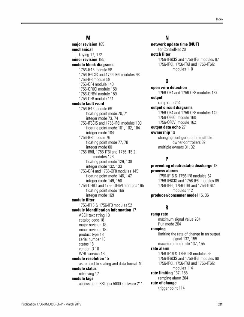
Index
Mmajor revision 185mechanical
keying 17, 172minor revision 185module block diagrams
1756-IF16 module 581756-IF6CIS and 1756-IF6I modules 931756-IF8 module 581756-OF4 module 1401756-OF6CI module 1581756-OF6VI module 1591756-OF8 module 141
module fault word1756-IF16 module 69
floating point mode 70, 71integer mode 73, 74
1756-IF6CIS and 1756-IF6I modules 100floating point mode 101, 102, 104integer mode 104
1756-IF8 module 76floating point mode 77, 78integer mode 80
1756-IR6I, 1756-IT6I and 1756-IT6I2 modules 128
floating point mode 129, 130integer mode 132, 133
1756-OF4 and 1756-OF8 modules 145floating point mode 146, 147integer mode 149, 150
1756-OF6CI and 1756-OF6VI modules 165floating point mode 166integer mode 169
module filter1756-IF16 & 1756-IF8 modules 52
module identification information 17ASCII text string 18catalog code 18major revision 18minor revision 18product type 18serial number 18status 18vendor ID 18WHO service 18
module resolution 15as related to scaling and data format 40
module statusretrieving 17
module tagsaccessing in RSLogix 5000 software 211
Nnetwork update time (NUT)
for ControlNet 20notch filter
1756-IF6CIS and 1756-IF6I modules 871756-IR6I, 1756-IT6I and 1756-IT6I2
modules 110
Oopen wire detection
1756-OF4 and 1756-OF8 modules 137output
ramp rate 204output circuit diagrams
1756-OF4 and 1756-OF8 modules 1421756-OF6CI module 1601756-OF6VI module 162
output data echo 27ownership 19
changing configuration in multiple owner-controllers 32
multiple owners 31, 32
Ppreventing electrostatic discharge 18process alarms
1756-IF16 & 1756-IF8 modules 541756-IF6CIS and 1756-IF6I modules 891756-IR6I, 1756-IT6I and 1756-IT6I2
modules 112producer/consumer model 15, 36
Rramp rate
maximum signal value 204Run mode 204
rampinglimiting the rate of change in an output
signal 137, 155maximum ramp rate 137, 155
rate alarm1756-IF16 & 1756-IF8 modules 551756-IF6CIS and 1756-IF6I modules 901756-IR6I, 1756-IT6I and 1756-IT6I2
modules 114rate limiting 137, 155
ramping alarm 204rate of change
trigger point 114
Publication 1756-UM009D-EN-P - March 2015 321
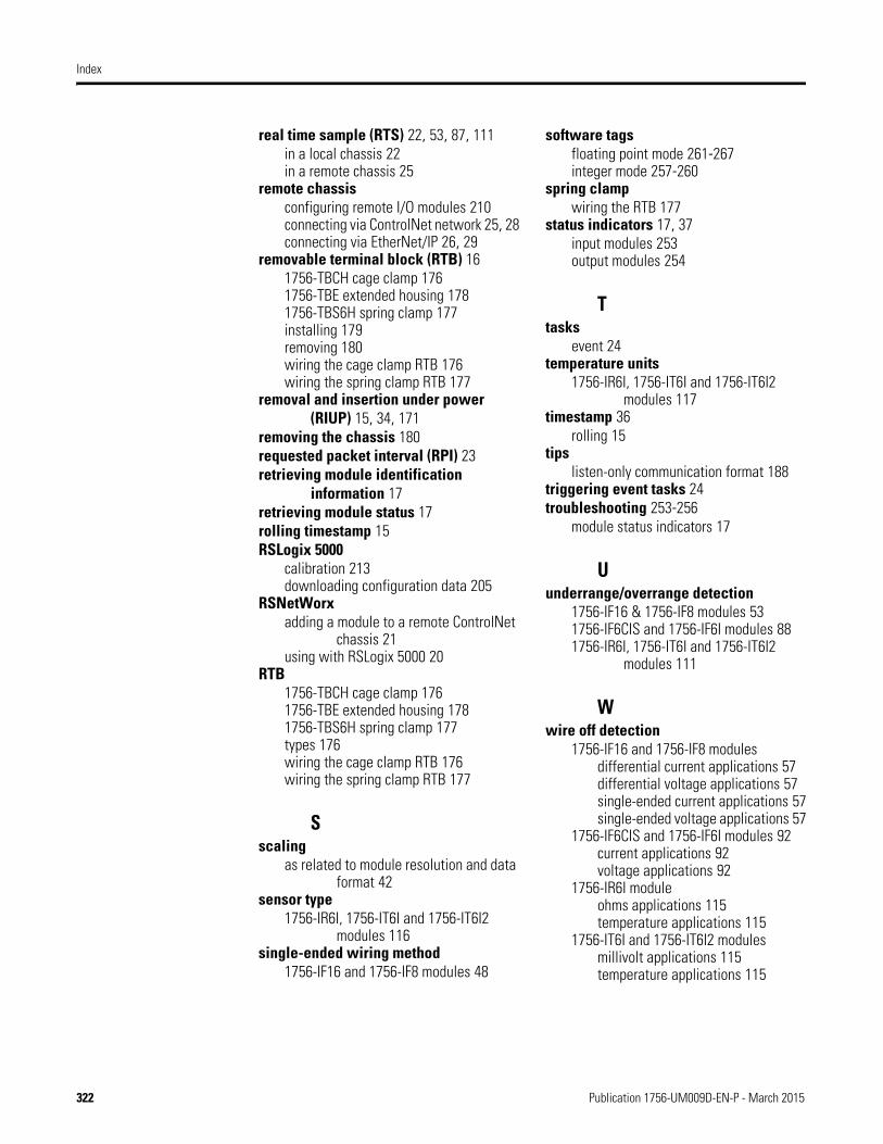
Index
real time sample (RTS) 22, 53, 87, 111in a local chassis 22in a remote chassis 25
remote chassisconfiguring remote I/O modules 210connecting via ControlNet network 25, 28connecting via EtherNet/IP 26, 29
removable terminal block (RTB) 161756-TBCH cage clamp 1761756-TBE extended housing 1781756-TBS6H spring clamp 177installing 179removing 180wiring the cage clamp RTB 176wiring the spring clamp RTB 177
removal and insertion under power (RIUP) 15, 34, 171
removing the chassis 180requested packet interval (RPI) 23retrieving module identification
information 17retrieving module status 17rolling timestamp 15RSLogix 5000
calibration 213downloading configuration data 205
RSNetWorxadding a module to a remote ControlNet
chassis 21using with RSLogix 5000 20
RTB1756-TBCH cage clamp 1761756-TBE extended housing 1781756-TBS6H spring clamp 177types 176wiring the cage clamp RTB 176wiring the spring clamp RTB 177
Sscaling
as related to module resolution and data format 42
sensor type1756-IR6I, 1756-IT6I and 1756-IT6I2
modules 116single-ended wiring method
1756-IF16 and 1756-IF8 modules 48
software tagsfloating point mode 261-267integer mode 257-260
spring clampwiring the RTB 177
status indicators 17, 37input modules 253output modules 254
Ttasks
event 24temperature units
1756-IR6I, 1756-IT6I and 1756-IT6I2 modules 117
timestamp 36rolling 15
tipslisten-only communication format 188
triggering event tasks 24troubleshooting 253-256
module status indicators 17
Uunderrange/overrange detection
1756-IF16 & 1756-IF8 modules 531756-IF6CIS and 1756-IF6I modules 881756-IR6I, 1756-IT6I and 1756-IT6I2
modules 111
Wwire off detection
1756-IF16 and 1756-IF8 modulesdifferential current applications 57differential voltage applications 57single-ended current applications 57single-ended voltage applications 57
1756-IF6CIS and 1756-IF6I modules 92current applications 92voltage applications 92
1756-IR6I moduleohms applications 115temperature applications 115
1756-IT6I and 1756-IT6I2 modulesmillivolt applications 115temperature applications 115
322 Publication 1756-UM009D-EN-P - March 2015
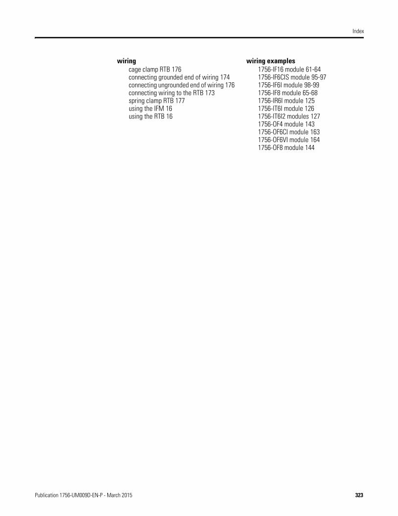
Index
wiringcage clamp RTB 176connecting grounded end of wiring 174connecting ungrounded end of wiring 176connecting wiring to the RTB 173spring clamp RTB 177using the IFM 16using the RTB 16
wiring examples1756-IF16 module 61-641756-IF6CIS module 95-971756-IF6I module 98-991756-IF8 module 65-681756-IR6I module 1251756-IT6I module 1261756-IT6I2 modules 1271756-OF4 module 1431756-OF6CI module 1631756-OF6VI module 1641756-OF8 module 144
Publication 1756-UM009D-EN-P - March 2015 323

Index
Notes:
324 Publication 1756-UM009D-EN-P - March 2015

Publication 1756-UM009D-EN-P - March 2015Supersedes Publication 1756-UM009C-EN-P - December 2010 Copyright © 2015 Rockwell Automation, Inc. All rights reserved. Printed in the U.S.A.
Rockwell Automation Support
Rockwell Automation provides technical information on the Web to assist you in using its products.At http://www.rockwellautomation.com/support you can find technical and application notes, sample code, and links to software service packs. You can also visit our Support Center at https://rockwellautomation.custhelp.com/ for software updates, support chats and forums, technical information, FAQs, and to sign up for product notification updates.
In addition, we offer multiple support programs for installation, configuration, and troubleshooting. For more information, contact your local distributor or Rockwell Automation representative, or visithttp://www.rockwellautomation.com/services/online-phone.
Installation Assistance
If you experience a problem within the first 24 hours of installation, review the information that is contained in this manual. You can contact Customer Support for initial help in getting your product up and running.
New Product Satisfaction Return
Rockwell Automation tests all of its products to help ensure that they are fully operational when shipped from the manufacturing facility. However, if your product is not functioning and needs to be returned, follow these procedures.
Documentation Feedback
Your comments will help us serve your documentation needs better. If you have any suggestions on how to improve this document, complete this form, publication RA-DU002, available at http://www.rockwellautomation.com/literature/.
United States or Canada 1.440.646.3434
Outside United States or Canada Use the Worldwide Locator at http://www.rockwellautomation.com/rockwellautomation/support/overview.page, or contact your local Rockwell Automation representative.
United States Contact your distributor. You must provide a Customer Support case number (call the phone number above to obtain one) to your distributor to complete the return process.
Outside United States Please contact your local Rockwell Automation representative for the return procedure.
Rockwell Otomasyon Ticaret A.Ş., Kar Plaza İş Merkezi E Blok Kat:6 34752 İçerenköy, İstanbul, Tel: +90 (216) 5698400
Rockwell Automation maintains current product environmental information on its website athttp://www.rockwellautomation.com/rockwellautomation/about-us/sustainability-ethics/product-environmental-compliance.page.