Embed Size (px)
Citation preview
Controlling Wild Mobile RobotsUsing Virtual Gates and Discrete Transitions
Leonardo Bobadilla Fredy Martinez Eric [email protected] [email protected] [email protected]
Katrina Gossman Steven M. [email protected] [email protected]
Department of Computer ScienceUniversity of Illinois
Urbana, IL 61801 USA
Abstract—We present an approach to controlling multiplemobile robots without requiring system identification, geometricmap building, localization, or state estimation. Instead, wepurposely design them to execute wild motions, which meanseach will strike every open set infinitely often along the boundaryof any connected region in which it is placed. We then divide theenvironment into a discrete set of regions, with borders delineatedwith simple markers, such as colored tape. Using simple sensorfeedback, we show that complex tasks can be solved, such aspatrolling, disentanglement, and basic navigation. The method isimplemented in simulation and on real robots, which for manytasks are fully distributed without any mutual communication.
I. I NTRODUCTION
With advances in technology, mobile robots are increasinglyequipped with rich sensors, powerful control boards, high-performance computers, and high-speed communication links.This has enabled the development of highly sophisticatedsystems for common tasks such as navigation, exploration,patrolling, and coverage. This usually leads to a significantmodeling burden, which includes system identification andcareful mapping of the robot’s environment. Powerful sensorsare used for mapping and localization. Filters are developed toobtain state estimates so that policies based on state feedbackcan be designed and implemented. Further complications arisein the case of multiple robots: Careful coordination andcommunication strategies are usually developed, sometimesinvolving a centralized controller.
In this paper, we explore the development of mobile robotsystems from the opposite extreme: How absurdly simple canthe system be while nevertheless accomplishing interestingtasks? There are several important reasons to focus on simple,minimalist robots. First of all, theoretically, it encourages usto find what is the least amount of information needed tosolve a certain task, giving insights into the task’s inherentcomplexity. Secondly, this may allow us to manufacture robust,inexpensive robots with low energy consumption, which isimportant in the case of multiple robots. Thirdly, sensorscan be limited depending on the environment. For example,most indoor environments are GPS-denied, lighting conditionscan affect computer vision based approaches, and the useof cameras in public spaces may be frowned upon due to
privacy concerns. Finally, in some settings, especially microand nanorobotics, the sensors, actuators, and system modelsare all poor. Insights from effectively controlling robotsina larger scale, but with weak components, may give offerinsights into achieving tasks in these difficult settings.
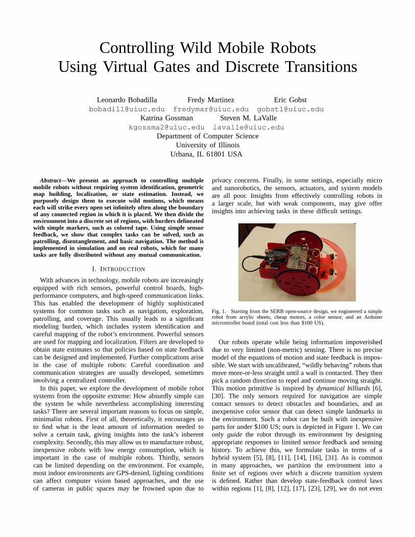
Fig. 1. Starting from the SERB open-source design, we engineered a simplerobot from acrylic sheets, cheap motors, a color sensor, and an Arduinomicrontroller board (total cost less than $100 US).
Our robots operate while being information impoverisheddue to very limited (non-metric) sensing. There is no precisemodel of the equations of motion and state feedback is impos-sible. We start with uncalibrated, “wildly behaving” robots thatmove more-or-less straight until a wall is contacted. They thenpick a random direction to repel and continue moving straight.This motion primitive is inspired bydynamical billiards[6],[30]. The only sensors required for navigation are simplecontact sensors to detect obstacles and boundaries, and aninexpensive color sensor that can detect simple landmarks inthe environment. Such a robot can be built with inexpensiveparts for under $100 US; ours is depicted in Figure 1. We canonly guide the robot through its environment by designingappropriate responses to limited sensor feedback and sensinghistory. To achieve this, we formulate tasks in terms of ahybrid system [5], [8], [11], [14], [16], [31]. As is commonin many approaches, we partition the environment into afinite set of regions over which a discrete transition systemis defined. Rather than develop state-feedback control lawswithin regions [1], [8], [12], [17], [23], [29], we do not even
attempt to stabilize the robots. We instead placevirtual gatesalong the boundaries between regions that possibly enablediscrete transitions, depending on information provided by acombinatorial filter [25], [32] that maintains informationstatesfrom weak sensor data. In related work, mechanical gateswere designed and demonstrated to allow various tasks to beeffectively solved [4]. In that work, tasks were specified usingthe LTL framework (see [3], [9], [10], [12], [17], [19], [20],[21], [22], [23], [29], [34]) and then converted into solutionstrategies using model checking software. In the current paper,we instead explore the idea ofvirtual gates, which allow adifferent set of tasks to be solved. It remains an open problemto design logics that can adequately capture the set of tasksthat are solvable using the approach in this paper.
The paper is organized as follows. Section II presentspreliminary concepts, including the interaction between thewild robots, the virtual gates, and the regions. Section IIIpresents experiments for multi-robot tasks that are solvedwithour approach. Section IV presents extensions and open issues,and Section V concludes the paper.
II. M ATHEMATICAL MODEL
A collection of n robots (numbered1 to n) is placed intoa compact, connected planar workspaceW ⊂ R
2. Let ∂Wdenote the boundary ofW. Let Γ be a set ofm virtual gates,for which eachγi ∈ Γ is the image of an injective, rectifiablecurveτi : [0, 1] → W for which τ(0) ∈ ∂W andτ(1) ∈ ∂W.Let C be a set ofk colors, with k ≤ m. Each virtual gate islabeled with a color by a given mappingκ : Γ → C.
The gates induce a decomposition ofW into connectedcells. See Figure 2 for an example. If the gates inΓ arepairwise disjoint, then eachγi ∈ Γ is a 1-cell and the 2-cells are maximal regions bounded by 1-cells and intervals of∂W. If gates intersect, then the 1-cells are maximal intervalsbetween any gate intersection points or elements of∂W; the2-cells follow accordingly. In either case, every 2-cell will becalled aregionand denoted asR. Let R denote the collectionof all regions.
Fig. 2. An annulus-shaped environment that has6 regions. The walls aremade of bricks and the virtual gates are made of colored tape. There are threeRED gates and threeWHITE gates.
The robots are considered small with respect toW andthe regionsR ∈ R. They are essentially modeled as points,but may have specific kinematics, as in the common case ofdifferential drive robots. More precisely, the assumptionisthat the collision-free subsets ofW and everyR ∈ R are
homeomorphic to those obtained for the case of a point robot,regardless of each robot’s geometry (for example, the radiusof a disc robot). Furthermore, anyR ∈ R is assumed to beable to fit alln robots without complicated geometric packingchallenges [28].
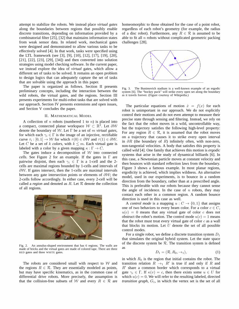
Fig. 3. The Bunimovich stadium is a well-known example of an ergodicsystem [6]. The “hockey puck” will strike every open set along the boundaryas it travels forever. (Figure courtesy of Wikipedia.)
The particular equations of motionx = f(x) for eachrobot is unimportant in our approach. We do not explicitlycontrol their motions and do not even attempt to measure theirprecise state through sensing and filtering. Instead, we rely onthe fact that the robot moves in a wild, uncontrollable way,but the trajectory satisfies the following high-level property:For any regionR ∈ R, it is assumed that the robot moveson a trajectory that causes it to strike every open intervalin ∂R (the boundary ofR) infinitely often, with non-zero,non-tangential velocities. A body that satisfies this property iscalledwild [4]. One family that achieves this motion isergodicsystems that arise in the study of dynamical billiards [6]. Inthis case, a Newtonian particle moves at constant velocity andthen bounces with standard reflection laws from the boundary.Figure 3 shows a famous example. In most planar regions,ergodicity is achieved, which implies wildness. An alternativemodel, used in our experiments, is to bounce in a randomdirection from the boundary, rather than at a prescribed angle.This is preferable with our robots because they cannot sensethe angle of incidence. In the case ofn robots, they maycontact each other in a common region. A random bouncedirection is used in this case as well.
A control modeis a mappingu : C → {0, 1} that assignsone of two behaviors to every beam color. For a colorc ∈ C,u(c) = 0 means that any virtual gate of colorc does notobstruct the robot’s motion. The control modeu(c) = 1 meansthat the robot must treat every virtual gate of colorc as a wallthat blocks its motion. LetU denote the set of all possiblecontrol modes.
For a single robot, we define a discrete transition systemD1
that simulates the original hybrid system. Let the state spaceof the discrete system beR. The transition system is definedas
D1 = (R, R0,→1), (1)
in which R0 is the region that initial contains the robot. Thetransition relationR →1 R′ is true if and only if R andR′ share a common border which corresponds to a virtualgateγi ∈ Γ. If κ(v) = c, then there exists someu ∈ U forwhichu(c) = 0. We will refer to the resulting labeled, directedtransition graph, G1, in which the vertex set is the set of all
regionsR, and every edge is a possible transition, labeled bythe virtual gate color that allows it.
It is straightforward to show thatD1 is a simulation of theoriginal hybrid system. Therefore, we can design a solutionplan overD1, thereby inducing the correct behavior of theoriginal hybrid system. This is the standard approach to hybridsystem control using a discrete abstraction. In the case ofnrobots,D1 is extended in the obvious way by making ann-fold Cartesian product of the transition graph. This results ina discrete transition systemDn that simulates the motions ofall robots.
We develop an event-based system [2]. Each robot startswith an initial control mode. During execution, the controlmode may change only when receiving an sensor observationeventy. Depending on the system, the possible events are:
1) Gate crossing:The robot detects that it crossed a virtualgate of colorc. The observation isy = c.
2) Timer expire: The robot has been within a single regionfor at leastt seconds. The observation isy = TIMEOUT.
3) Change in lighting: The ambient room light changed,either asy = LIGHTTODARK or y = DARKTOLIGHT.
4) Communication: The robot receives a message fromrobot i that roboti crossed beamc. The observation isy = (c, i).
Let Y denote the set of all possible observation events for arobot in a particular system.
The control modes of roboti are set during executionaccording to a policy. Since state feedback is not possible,information feedbackis instead used. Let afilter be anymapping of the formφ : I × Y → I, in which I denotesan information space[24] that is designed appropriately forthe task (this should become clear in Section III). The initialη ∈ I is given, and each time a new observation eventoccurs, an information-state transition occurs in the filter. Acontrol policyis specified as an information-feedback mappingπ : I → U , which enables the control mode to be setaccording to the sensor observation history.
III. SOLVING TASKS
In this section, we present a series of tasks that were solvedby our method. First, we describe our simple differentialrobots, and then we present solved tasks that take into accountdifferent information spaces, filters and control polices.Fullvideos appear at
http://msl.cs.uiuc.edu/virtualgates/
A. Hardware
Our robots are based on the Oomlout open-source SERBdesign (http://www.oomlout.com/a/products/serb/). We modi-fied the design to have a more robust bumper system using asimilar geometry to the SERB robot chassis. Also, a ParallaxColorPAL sensor was added to the newly designed bumpersystem so that both physical and virtual walls can be detectedwith a simple attachment. Each robot can be made for under$100 US from commercially available parts and is depicted inthe Figure 1. The robot frame and wheels were cut from in-expensive 1/8-inch acrylic plates. Each robot uses an ArduinoDuemilanove board, which includes an 8-bit microcontroller
with a 16 Mhz clock that runs off a 9V battery. Continuousservos made by Parallax are used to move the large wheelsof the robot. A solderless breadboard is attached to the top ofthe robot to allow quick circuit modifications. A 4-AA batterypack is attached under the robot to provide separate power tothe servo motors.
B. Patrolling
For this task, we would like a set of robots to visit all ofthe regions inR repeatedly, in some specified order. In thiscase, we compute any cyclic path throughG1 and then assigna color to every edge, which corresponds to a virtual gate.Colors may be reused, provided that ambiguity does not arise.Figure 2 shows an example environment in which two colorsare sufficient, resulting inC = {RED, WHITE}. These are theonly observation events, leading toY = C. There are twocontrol modes:U = {u0, u1}. The first,u0, allows the robotto cross a white gate,u0(WHITE) = 0 but treats red as awall u0(RED) = 1. The second,u1, has the opposite effect:u1(WHITE) = 1 andu1(RED) = 0. To achieve patrolling, wedesign a small information spaceI = {η0, η1}. The controlpolicy π is defined asui = π(ηi) for i ∈ {0, 1}.
RED
WHITE=y
=y
Fig. 4. Simple filter used for patrolling
The filter φ switches information states when a color iscrossed as follows:η1 = φ(η0, WHITE) andη0 = φ(η1, RED).See Figure 4. When bouncing occurs from a virtual gate, it isassumed that no observation event occurs because the robotdoes not pass through the gate. Therefore, the filter in Figure 4shows no edges for the cases ofφ(η0, RED) andφ(η1, WHITE).
Depending on the initial regionR ∈ R and initial infor-mation stateη ∈ I, a robot that executesπ will indefinitelypatrol the6 regions in clockwise or counterclockwise order.Suppose that the initial state of the robot isη0 which makes itgo through a white gate. When it crosses the white gate, it willtransition toη1. This will make the white gate into a virtualwall forcing it to remain in the new region until the red gateis crossed. An implementation is shown in Figure 5 in which4 robots execute the same policyπ, but with different initialregions and information states to induce various directions ofpatrolling.
C. Separating into teams
For another task, suppose we have twoteamsof robotsthat are initially in one region and we would like to separatethem into one team per region. To solve this problem, weuse the same filter and control law described in the previoussubsection. We require that members of the same team havethe same initial information state. We implemented this taskwith four robots belonging to two different teams, blue andnot blue (Figure 6).
(a) (b)
(c) (d)
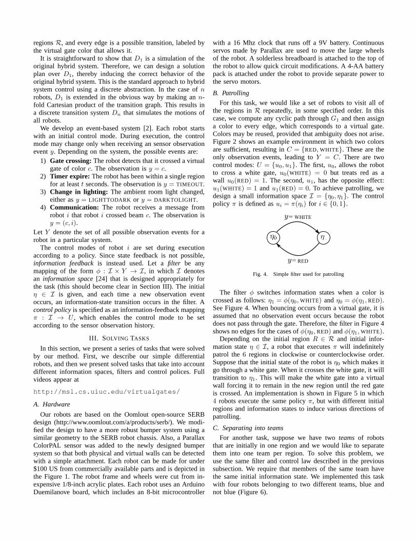
Fig. 5. Continuous patrolling of the environment: a) Four robots start indifferent regions. The first group (blue robots) is allowed to cross the whitegate, the second group (red and white) is allowed to cross thered gate; b)after 36 seconds, the four robots have advanced to the following regions,blue robots clockwise, and red and white robots counterclockwise; c) after44seconds, the blue robots and the red robot cross into a regionbut in oppositedirections, the white robot is about to end its first round trip; d) after 69seconds, the white robot begins its second round trip while the other threerobots are near completion of the first.
(a) (b)
(c) (d)
Fig. 6. Autonomous separation of robots into two teams: a) Fourrobotsstart simultaneously in the same region in the center of the environment (thereare three regions total); b) after16 seconds, the gold robot has reached thelower region, and one blue robot has reached the upper region; c) after 24seconds, the second blue robot has reached the upper region,and the redrobot has reached the lower region; (d) after38 seconds, the four robotsremain separated in their regions.
D. Navigation
We want a group of robots to navigate in an environmentcontaining alternating colored gates. The goal is for the robotsto move from one end region to another as illustrated inFigure 7. The only additional information, with respect tothe previous examples, is that the robot must choose aninformation stateη0 or η1 depending on which virtual gateis crossed first.
E. Reactive tasks
We would also like to give the robots the ability to changetheir policies based on information collected from externalenvironment conditions that appear during run time. This canbe easily incorporated in our framework by adding simplesensors. For example, we placed inexpensive photo diodes (for
(a) (b)
(c) (d)
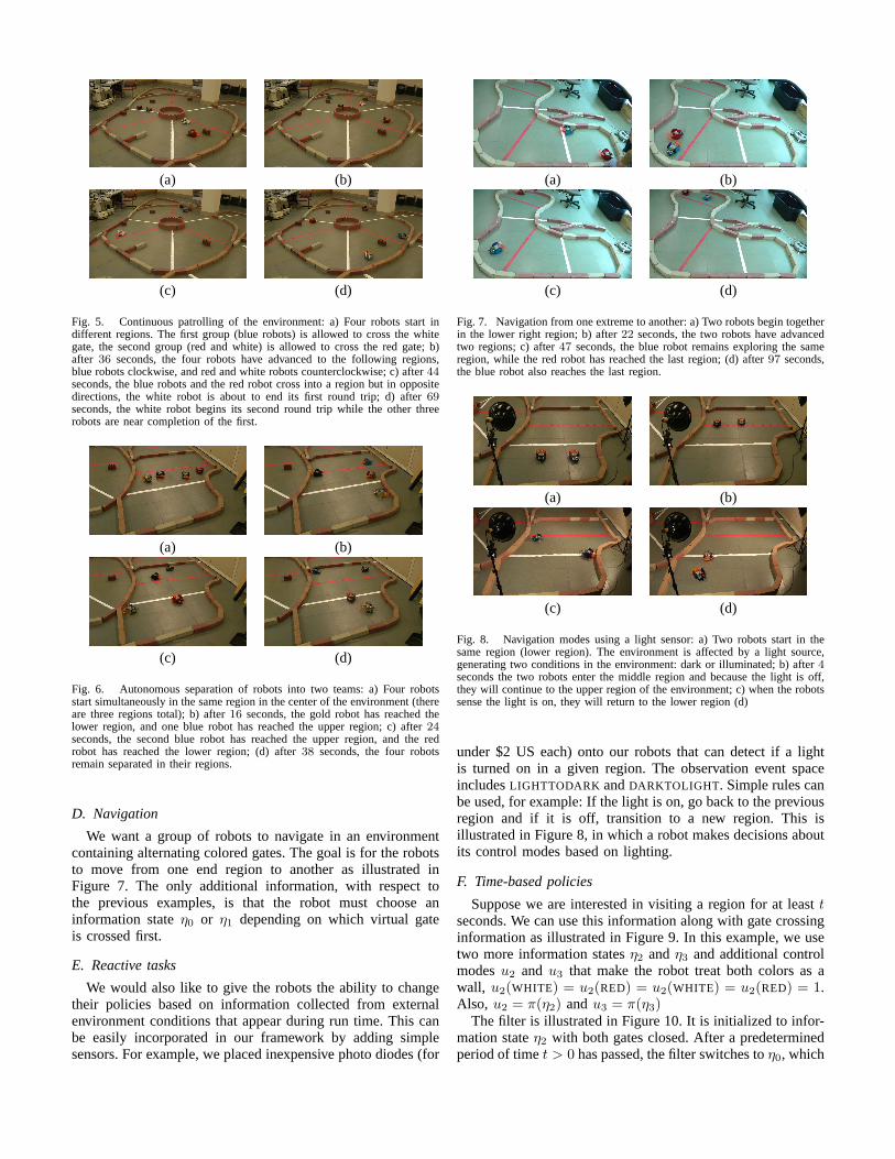
Fig. 7. Navigation from one extreme to another: a) Two robots begin togetherin the lower right region; b) after22 seconds, the two robots have advancedtwo regions; c) after47 seconds, the blue robot remains exploring the sameregion, while the red robot has reached the last region; (d) after 97 seconds,the blue robot also reaches the last region.
(a) (b)
(c) (d)
Fig. 8. Navigation modes using a light sensor: a) Two robots start in thesame region (lower region). The environment is affected by a light source,generating two conditions in the environment: dark or illuminated; b) after4seconds the two robots enter the middle region and because thelight is off,they will continue to the upper region of the environment; c) when the robotssense the light is on, they will return to the lower region (d)
under $2 US each) onto our robots that can detect if a lightis turned on in a given region. The observation event spaceincludesLIGHTTODARK andDARKTOLIGHT. Simple rules canbe used, for example: If the light is on, go back to the previousregion and if it is off, transition to a new region. This isillustrated in Figure 8, in which a robot makes decisions aboutits control modes based on lighting.
F. Time-based policies
Suppose we are interested in visiting a region for at leasttseconds. We can use this information along with gate crossinginformation as illustrated in Figure 9. In this example, we usetwo more information statesη2 andη3 and additional controlmodesu2 and u3 that make the robot treat both colors as awall, u2(WHITE) = u2(RED) = u2(WHITE) = u2(RED) = 1.Also, u2 = π(η2) andu3 = π(η3)
The filter is illustrated in Figure 10. It is initialized to infor-mation stateη2 with both gates closed. After a predeterminedperiod of timet > 0 has passed, the filter switches toη0, which
(a) (b)
(c) (d)
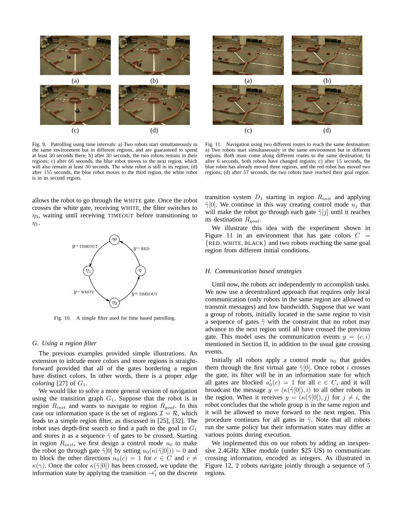
Fig. 9. Patrolling using time intervals: a) Two robots start simultaneously inthe same environment but in different regions, and are guaranteed to spendat least30 seconds there; b) after30 seconds, the two robots remain in theirregions; c) after66 seconds, the blue robot moves to the next region, whichwill also remain at least30 seconds. The white robot is still in its region; (d)after 155 seconds, the blue robot moves to the third region, the white robotis in its second region.
allows the robot to go through theWHITE gate. Once the robotcrosses the white gate, receivingWHITE, the filter switches toη3, waiting until receivingTIMEOUT before transitioning toη1.
RED
WHITE
TIMEOUT
TIMEOUT
=y
=y
=y
=y
Fig. 10. A simple filter used for time based patrolling.
G. Using a region filter
The previous examples provided simple illustrations. Anextension to inlcude more colors and more regions is straight-forward provided that all of the gates bordering a regionhave distinct colors. In other words, there is a properedgecoloring [27] of G1.
We would like to solve a more general version of navigationusing the transition graphG1. Suppose that the robot is inregion Rinit and wants to navigate to regionRgoal. In thiscase our information space is the set of regionsI = R, whichleads to a simple region filter, as discussed in [25], [32]. Therobot uses depth-first search to find a path to the goal inG1
and stores it as a sequenceγ of gates to be crossed. Startingin region Rinit, we first design a control modeu0 to makethe robot go through gateγ[0] by settingu0(κ(γ[0])) = 0 andto block the other directionsu0(c) = 1 for c ∈ C and c 6=κ(γ). Once the colorκ(γ[0]) has been crossed, we update theinformation state by applying the transition→′
1on the discrete
(a) (b)
(c) (d)
Fig. 11. Navigation using two different routes to reach the same destination:a) Two robots start simultaneously in the same environment but in differentregions. Both must come along different routes to the same destination; b)after 6 seconds, both robots have changed regions; c) after15 seconds, theblue robot has already moved three regions, and the red robot has moved tworegions; (d) after57 seconds, the two robots have reached their goal region.
transition systemD1 starting in regionRinit and applyingγ[0]. We continue in this way creating control modeuj thatwill make the robot go through each gateγ[j] until it reachesits destinationRgoal.
We illustrate this idea with the experiment shown inFigure 11 in an environment that has gate colorsC ={RED, WHITE, BLACK} and two robots reaching the same goalregion from different initial conditions.
H. Communication based strategies
Until now, the robots act independently to accomplish tasks.We now use a decentralized approach that requires only localcommunication (only robots in the same region are allowed totransmit messages) and low bandwidth. Suppose that we wanta group of robots, initially located in the same region to visita sequence of gatesγ with the constraint that no robot mayadvance to the next region until all have crossed the previousgate. This model uses the communication eventsy = (c, i)mentioned in Section II, in addition to the usual gate crossingevents.
Initially all robots apply a control modeu0 that guidesthem through the first virtual gateγ[0]. Once roboti crossesthe gate, its filter will be in an information state for whichall gates are blockedu′
0(c) = 1 for all c ∈ C, and it will
broadcast the messagey = (κ(γ[0]), i) to all other robots inthe region. When it receivesy = (κ(γ[0]), j) for j 6= i, therobot concludes that the whole group is in the same region andit will be allowed to move forward to the next region. Thisprocedure continues for all gates inγ. Note that all robotsrun the same policy but their information states may differ atvarious points during execution.
We implemented this on our robots by adding an inexpen-sive 2.4GHz XBee module (under $25 US) to communicatecrossing information, encoded as integers. As illustratedinFigure 12,2 robots navigate jointly through a sequence of5regions.
(a) (b)
(c) (d)
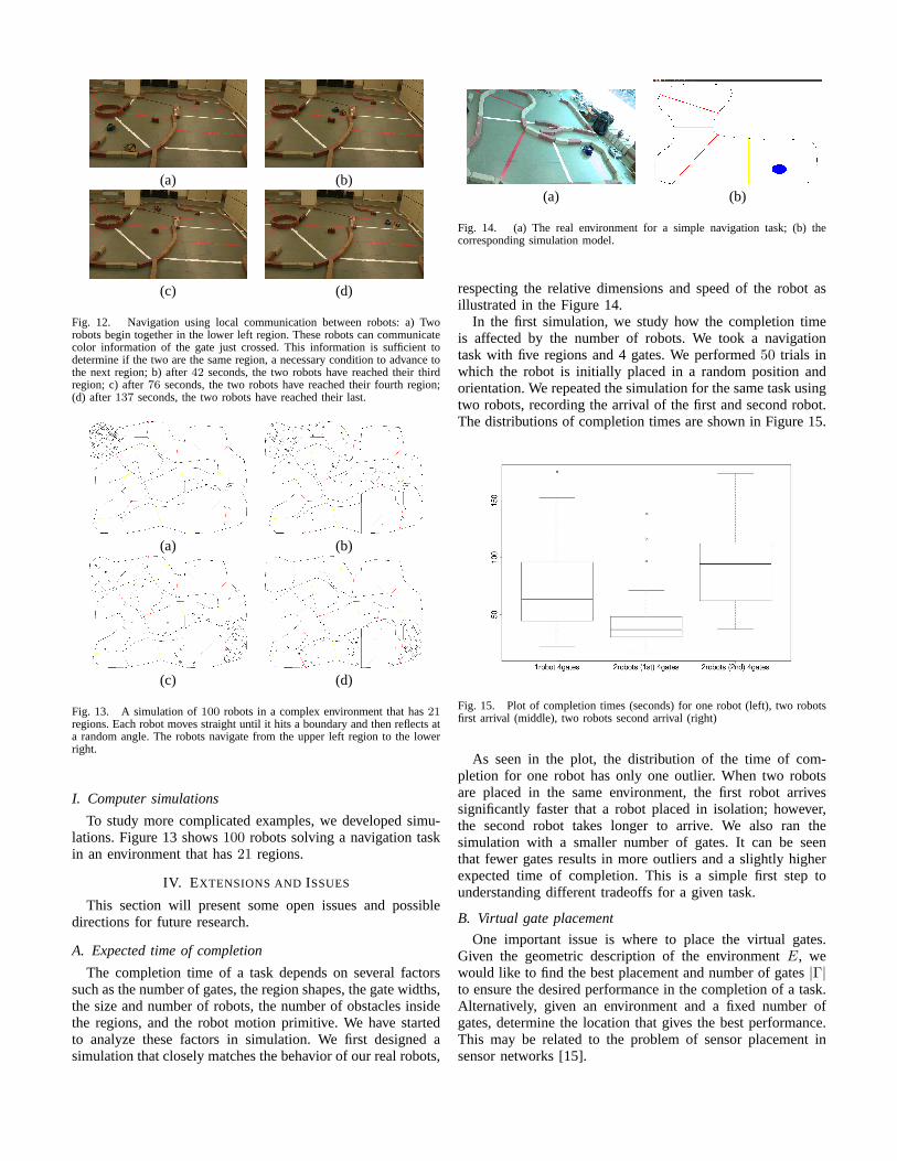
Fig. 12. Navigation using local communication between robots: a) Tworobots begin together in the lower left region. These robotscan communicatecolor information of the gate just crossed. This information is sufficient todetermine if the two are the same region, a necessary conditionto advance tothe next region; b) after42 seconds, the two robots have reached their thirdregion; c) after76 seconds, the two robots have reached their fourth region;(d) after137 seconds, the two robots have reached their last.
(a) (b)
(c) (d)
Fig. 13. A simulation of100 robots in a complex environment that has21
regions. Each robot moves straight until it hits a boundary and then reflects ata random angle. The robots navigate from the upper left region to the lowerright.
I. Computer simulations
To study more complicated examples, we developed simu-lations. Figure 13 shows100 robots solving a navigation taskin an environment that has21 regions.
IV. EXTENSIONS AND ISSUES
This section will present some open issues and possibledirections for future research.
A. Expected time of completion
The completion time of a task depends on several factorssuch as the number of gates, the region shapes, the gate widths,the size and number of robots, the number of obstacles insidethe regions, and the robot motion primitive. We have startedto analyze these factors in simulation. We first designed asimulation that closely matches the behavior of our real robots,
(a) (b)
Fig. 14. (a) The real environment for a simple navigation task;(b) thecorresponding simulation model.
respecting the relative dimensions and speed of the robot asillustrated in the Figure 14.
In the first simulation, we study how the completion timeis affected by the number of robots. We took a navigationtask with five regions and 4 gates. We performed50 trials inwhich the robot is initially placed in a random position andorientation. We repeated the simulation for the same task usingtwo robots, recording the arrival of the first and second robot.The distributions of completion times are shown in Figure 15.
Fig. 15. Plot of completion times (seconds) for one robot (left), two robotsfirst arrival (middle), two robots second arrival (right)
As seen in the plot, the distribution of the time of com-pletion for one robot has only one outlier. When two robotsare placed in the same environment, the first robot arrivessignificantly faster that a robot placed in isolation; however,the second robot takes longer to arrive. We also ran thesimulation with a smaller number of gates. It can be seenthat fewer gates results in more outliers and a slightly higherexpected time of completion. This is a simple first step tounderstanding different tradeoffs for a given task.
B. Virtual gate placement
One important issue is where to place the virtual gates.Given the geometric description of the environmentE, wewould like to find the best placement and number of gates|Γ|to ensure the desired performance in the completion of a task.Alternatively, given an environment and a fixed number ofgates, determine the location that gives the best performance.This may be related to the problem of sensor placement insensor networks [15].
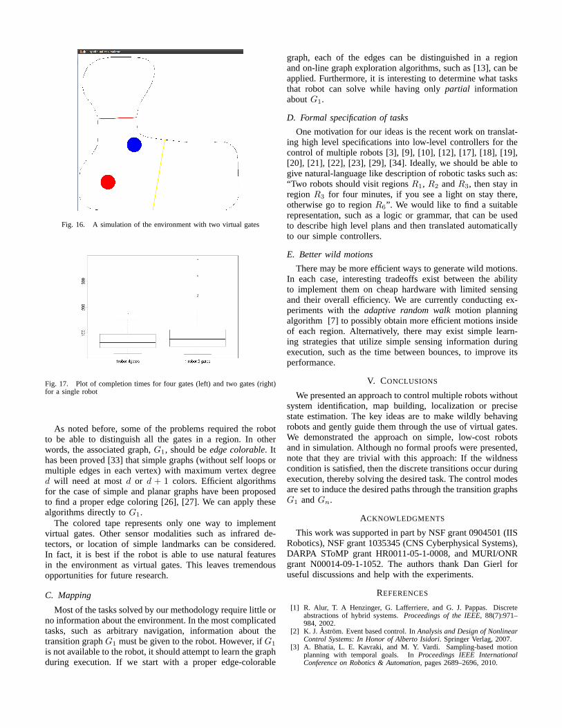
Fig. 16. A simulation of the environment with two virtual gates
Fig. 17. Plot of completion times for four gates (left) and two gates (right)for a single robot
As noted before, some of the problems required the robotto be able to distinguish all the gates in a region. In otherwords, the associated graph,G1, should beedge colorable. Ithas been proved [33] that simple graphs (without self loops ormultiple edges in each vertex) with maximum vertex degreed will need at mostd or d + 1 colors. Efficient algorithmsfor the case of simple and planar graphs have been proposedto find a proper edge coloring [26], [27]. We can apply thesealgorithms directly toG1.
The colored tape represents only one way to implementvirtual gates. Other sensor modalities such as infrared de-tectors, or location of simple landmarks can be considered.In fact, it is best if the robot is able to use natural featuresin the environment as virtual gates. This leaves tremendousopportunities for future research.
C. Mapping
Most of the tasks solved by our methodology require little orno information about the environment. In the most complicatedtasks, such as arbitrary navigation, information about thetransition graphG1 must be given to the robot. However, ifG1
is not available to the robot, it should attempt to learn the graphduring execution. If we start with a proper edge-colorable
graph, each of the edges can be distinguished in a regionand on-line graph exploration algorithms, such as [13], canbeapplied. Furthermore, it is interesting to determine what tasksthat robot can solve while having onlypartial informationaboutG1.
D. Formal specification of tasks
One motivation for our ideas is the recent work on translat-ing high level specifications into low-level controllers for thecontrol of multiple robots [3], [9], [10], [12], [17], [18],[19],[20], [21], [22], [23], [29], [34]. Ideally, we should be able togive natural-language like description of robotic tasks such as:“Two robots should visit regionsR1, R2 andR3, then stay inregionR3 for four minutes, if you see a light on stay there,otherwise go to regionR6”. We would like to find a suitablerepresentation, such as a logic or grammar, that can be usedto describe high level plans and then translated automaticallyto our simple controllers.
E. Better wild motions
There may be more efficient ways to generate wild motions.In each case, interesting tradeoffs exist between the abilityto implement them on cheap hardware with limited sensingand their overall efficiency. We are currently conducting ex-periments with theadaptive random walkmotion planningalgorithm [7] to possibly obtain more efficient motions insideof each region. Alternatively, there may exist simple learn-ing strategies that utilize simple sensing information duringexecution, such as the time between bounces, to improve itsperformance.
V. CONCLUSIONS
We presented an approach to control multiple robots withoutsystem identification, map building, localization or precisestate estimation. The key ideas are to make wildly behavingrobots and gently guide them through the use of virtual gates.We demonstrated the approach on simple, low-cost robotsand in simulation. Although no formal proofs were presented,note that they are trivial with this approach: If the wildnesscondition is satisfied, then the discrete transitions occurduringexecution, thereby solving the desired task. The control modesare set to induce the desired paths through the transition graphsG1 andGn.
ACKNOWLEDGMENTS
This work was supported in part by NSF grant 0904501 (IISRobotics), NSF grant 1035345 (CNS Cyberphysical Systems),DARPA SToMP grant HR0011-05-1-0008, and MURI/ONRgrant N00014-09-1-1052. The authors thank Dan Gierl foruseful discussions and help with the experiments.
REFERENCES
[1] R. Alur, T. A Henzinger, G. Lafferriere, and G. J. Pappas.Discreteabstractions of hybrid systems.Proceedings of the IEEE, 88(7):971–984, 2002.
[2] K. J. Astrom. Event based control. InAnalysis and Design of NonlinearControl Systems: In Honor of Alberto Isidori. Springer Verlag, 2007.
[3] A. Bhatia, L. E. Kavraki, and M. Y. Vardi. Sampling-based motionplanning with temporal goals. InProceedings IEEE InternationalConference on Robotics & Automation, pages 2689–2696, 2010.
[4] L. Bobadilla, O. Sanchez, J. Czarnowski, K. Gossman, and S. M.LaValle. Controlling wild bodies using linear temporal logic. InProceedings Robotics: Science and Systems, 2011.
[5] M. S. Branicky, V. S. Borkar, and S. K. Mitter. A unified framework forhybrid control: Model and optimal control theory.IEEE Transactionson Automatic Control, 43(1):31–45, 1998.
[6] L. A. Bunimovich. On the ergodic properties of nowhere dispersingbilliards. Communcations in Mathematical Physics, 65:295–312, 1979.
[7] S. Carpin and G. Pillonetto. Robot motion planning using adaptive ran-dom walks. IEEE Transactions on Robotics & Automation, 21(1):129–136, 2005.
[8] M. Egerstedt and X. Hu. A hybrid control approach to action coordi-nation for mobile robots.Automatica, 38(1):125–130, January 2001.
[9] G. E. Fainekos. Revising temporal logic specifications for motionplanning. InProceedings IEEE International Conference on Robotics& Automation, 2011.
[10] G. E. Fainekos, A. Girard, H. Kress-Gazit, and G. J. Pappas. Tem-poral logic motion planning for dynamic mobile robots.Automatica,45(2):343–352, February 2009.
[11] R. Fierro, A. Das, V. Kumar, and J. P. Ostrowski. Hybrid control offormations of robots. InProceedings IEEE International Conference onRobotics & Automation, pages 157–162, 2001.
[12] C. Finucane, G. Jing, and H. Kress-Gazit. LTLMoP: Experimentingwith language, temporal logic and robot control. InProceedingsIEEE/RSJ International Conference on Intelligent Robots and Systems,pages 1988–1993, 2010.
[13] P. Fraigniaud, D. Ilcinkas, G. Peer, A. Pelc, and D. Peleg. Graphexploration by a finite automaton.Theoretical Computer Science, 345(2-3):331–344, December 2005.
[14] E. Frazzoli, M. A. Dahleh, and E. Feron. Robust hybrid controlfor autonomous vehicles motion planning. Technical Report LIDS-P-2468, Laboratory for Information and Decision Systems, MassachusettsInstitute of Technology, 1999.
[15] C. Guestrin, A. Krause, and A. P. Singh. Near-optimal sensor placementsin gaussian processes. InProceedings International Conference onMachine Learning, 2005.
[16] E. Haghverdi, P. Tabuada, and G. J. Pappas. Bisimulationrelations fordynamical, control, and hybrid systems.Theoretical Computer Science,342(2-3):229–261, September 2005.
[17] M. Kloetzer and C. Belta. Automatic deployment of distributed teamsof robots from temporal logic motion specifications.IEEE Transactionson Robotics and Automation, 26(1):48–61, 2010.
[18] H. Kress-Gazit.Transforming high level tasks to low level controllers.PhD thesis, University of Pennsylvania, 2008.
[19] H. Kress-Gazit, G. E. Fainekos, and G. J. Pappas. Translating structuredenglish to robot controllers.Advanced Robotics, 22(12):1343–1359,2008.
[20] H. Kress-Gazit, G. E. Fainekos, and G. J. Pappas. Temporal-logic-basedreactive mission and motion planning.IEEE Transactions on Roboticsand Automation, 25(6):1370–1381, December 2009.
[21] H. Kress-Gazit, G.E. Fainekos, and G.J. Pappas. Temporal logicmotion planning for mobile robots. InProceedings IEEE InternationalConference on Robotics and Automation, 2005.
[22] H. Kress-Gazit, G.E. Fainekos, and G.J. Pappas. Where’sWaldo?sensor-based temporal logic motion planning. InProceedings IEEEInternational Conference on Robotics and Automation, 2007.
[23] M. Lahijanian, J. Wasniewski, S. B. Andersson, and C. Belta. Motionplanning and control from temporal logic specifications withprob-abilistic satisfaction guarantees. InProceedings IEEE InternationalConference on Robotics & Automation, pages 3227–3232, 2010.
[24] S. M. LaValle. Planning Algorithms. Cambridge University Press,Cambridge, U.K., 2006. Also available at http://planning.cs.uiuc.edu/.
[25] S. M. LaValle. Sensing and filtering: A tutorial based onpreimagesand information spaces.Foundations and Trends in Robotics, 2011. Toappear.
[26] J. Misra and D. Gries. A constructive proof of vizing’s theorem.Information Processing Letters, 41(3):131–133, 1992.
[27] S. Nakano, X. Zhou, and T. Nishizeki. Edge-coloring algorithms.Computer Science Today, pages 172–183, 1995.
[28] J. T. Schwartz and M. Sharir. On the Piano Movers’ Problem: III.Coordinating the motion of several independent bodies.InternationalJournal of Robotics Research, 2(3):97–140, 1983.
[29] S. L. Smith, J. Tumova, C. Belta, and D. Rus. Optimal path planningunder temporal logic constraints. InProceedings IEEE/RSJ InternationalConference on Intelligent Robots and Systems, pages 3288–3293, 2010.
[30] S. Tabachnikov. Geometry and Billiards. American MathematicalSociety, Providence, Rhode Island, 2005.
[31] C. Tomlin, G. J. Pappas, and S. Sastry. Conflict resolution for air trafficmanagement: A study in multiagent hybrid systems.IEEE Transactionson Automatic Control, 43(4):508–521, April 1998.
[32] B. Tovar, F. Cohen, and S. M. LaValle. Sensor beams, obstacles, andpossible paths. In G. Chirikjian, H. Choset, M. Morales, andT. Murphey,editors, Algorithmic Foundations of Robotics, VIII. Springer-Verlag,Berlin, 2009.
[33] V. G. Vizing. On an estimate of the chromatic class of a p-graph.Diskret.Analiz, 3(7):25–30, 1964.
[34] M. Wu, G. Yan, Z. Lin, and Y. Lan. Synthesis of output feedbackcontrol for motion planning based on LTL specifications. InProceedingsIEEE/RSJ International Conference on Intelligent Robots and Systems,pages 5071–5075, 2009.