Embed Size (px)
Citation preview

IAEA-TECDOC-1617
Controlling of Degradation Effectsin Radiation Processing of Polymers
May 2009

IAEA-TECDOC-1617
Controlling of Degradation Effectsin Radiation Processing of Polymers
May 2009

The originating Section of this publication in the IAEA was:
Industrial Applications in Chemistry Section International Atomic Energy Agency
Wagramer Strasse 5 P.O. Box 100
A-1400 Vienna, Austria
CONTROLLING OF DEGRADATION EFFECTS IN RADIATION PROCESSING OF POLYMERS
IAEA, VIENNA, 2009 ISBN 978–92–0–105109–7
ISSN 1011–4289 © IAEA, 2009
Printed by the IAEA in Austria May 2009
FOREWORD Since the beginning of radiation processing of polymers almost half a century ago, radiation crosslinking technologies have been extensively developed for useful commercial applications. The most well developed examples are the radiation crosslinking of wire insulation, heat shrinkable products for food packaging and electrical connections. The opposite of crosslinking namely, degradation which is used in the sense of chain scissioning here, has not been considered for long as an industrially desirable process and did not find sizeable applications. Controlled radiation degradation of polymers has now become an expanding technology encompassing the cleavage of polymer main chains, side chains or oxidative degradation. Established commercial processes based on the application of radiation degradation are now in place and a number of applications are in various stages of research, development and implementation. Radiation-induced degradation of synthetic polymers is utilized for the preparation of ion track membranes used in filtration and to prepare Teflon powder to be used in inks, lubricants and coatings. Another important application of radiation-induced degradation is in lithographic patterning. By using X rays and accelerated electrons it is possible to manufacture integrated circuits with radiation-patterned sub-micron dimensions. Natural polymers like cellulose (carboxy methyl cellulose) and other marine based polysaccharides (chitin/chitosan, alginates, carrageenans) are predominantly chain-scissioning polymers, and irradiation results in substantial decrease in molecular weight. This is accompanied with the formation of oxidation products and reduction in crystallinity. The degraded polysaccharides thus possess improved properties for applications in manufacturing of health care products, ingredients for cosmetics, plant growth promoters, viscosity modifiers in the food industry, and textile industry. The interest of Member States of the IAEA in introducing radiation technology into the polymer and plastics industry has led the IAEA to organize Coordinated Research Programmes on relevant topics. The first in this series was organized from 1994 to 1997 under the title The Stability and Stabilization of Polymers under Irradiation, with the objective of better understanding the factors affecting the stability of irradiated polymers, the main emphasis being on the enhancement of radiation-induced crosslinking. One of the main conclusions of the CRP was that much remained to be learned in terms of understanding degradation mechanism and phenomena. A consultants meeting on The Controlling of Degradation Effects in Radiation Processing of Polymers, held in 2002, provided an opportunity for extensive discussions by the experts of the subject on the recent developments and achievements of using radiation in controlled degradation of natural and synthetic polymers. The potential and use of ionizing radiation for controlled degradation of polymers have been considered from the points of view of: i) molecular weight modification, ii) bulk properties modification, and iii) surface modification. Following the recommendation of the consultants the IAEA established the CRP entitled Controlling of Degradation Effects in Radiation Processing of Polymers, covering the years 2003-2006. This technical publication compiles the most important results and achievements of the participating centers and laboratories during the course of the said CRP. It has been prepared to give first a comprehensive summary of the findings highlighting individual contributions and the full texts of scientific reports as prepared by the respective authors of the CRP. The IAEA wishes to thank all the participants for their valuable contributions, and O. Guven for the technical editing of this IAEA-TECDOC. The IAEA officer responsible for this publication was M.H. de Oliveira Sampa of the Division of Physical and Chemical Sciences.
EDITORIAL NOTE
The papers in these proceedings are reproduced as submitted by the authors and have not undergone rigorous editorial review by the IAEA.
The views expressed do not necessarily reflect those of the IAEA, the governments of the nominating Member States or the nominating organizations.
The use of particular designations of countries or territories does not imply any judgement by the publisher, the IAEA, as to the legal status of such countries or territories, of their authorities and institutions or of the delimitation of their boundaries.
The mention of names of specific companies or products (whether or not indicated as registered) does not imply any intention to infringe proprietary rights, nor should it be construed as an endorsement or recommendation on the part of the IAEA.
The authors are responsible for having obtained the necessary permission for the IAEA to reproduce, translate or use material from sources already protected by copyrights.
CONTENTS SUMMARY .......................................................................................................................................... 1 Effects of ionizing radiation on commercial food packaging ............................................................. 13
E.A.B. Moura, A.V. Ortiz, H. Wiebeck, A.B.A. Paula, A.O. Camargo, L.G.A. Silva Application of positron annihilation (PA) methods, together with conventional ones, to study the structural changes in some environmentally friendly polymers upon ionising radiation................................................................................................................ 41 M.A. Misheva Analysis of plasma treated metallized polymers and conventional polymers modified by various techniques .................................................................................................. 55
A. Macková Controlling of degradation effects in radiation processing of polymers ............................................. 67
E.A. Hegazy, H. Abdel-Rehim, D.A. Diaa, A. El-Barbary Effect of radiation on ultra high molecular weight polyethylene (UHMWPE)................................... 85
Sungsik Kim, Young Chang Nho
Modification of microstructures and physical properties of ultra high molecular weight polyethylene by electron beam irradiation .................................................................................. 95
Y.C. Nho, S.M. Lee, H.H. Song
Electrospinning of polycaprolactone and its degradation effect by radiation ................................... 1 07Y.C. Nho, J.-P. Jeun, Y.-M. Lim
Mitigation of degradation by different class of antioxidants in LDPE exposed to ionizing radiations................................................................................................................. 117
T. Yasin, S. Ahmed, Z.I. Zafar Influence of radiation on some physico-chemical properties of gum acacia..................................... 125
T. Yasin, S. Ahmed Radiation resistance of polypropylene modified by amine stabilizers versus PP copolymers.......... 129
Z. Zimek, G. Przybytniak, A. Rafalski, E. Kornacka Improvement in the thermal performance of polypropylene............................................................. 139
T. Zaharescu Effect of irradiation on polyolefin-based materials: 1. Polymorphism in conventional isotactic polypropylend by effect of gamma radiation ............................................................................................. 153
M.L. Cerrada, E. Pérez, C. Álvarez, A. Bello, R. Benavente, J.M. Pereña Effect of irradiation on polyolefin-based materials: 2. Effect of irradiation in metallocene polymeric materials: amorphous ethylene-norbonene copolymers and crystalline syndiotactic polypropylene ................................................................................................ 157
M.L. Cerrada, E. Pérez, A. Bello, R. Benavente, J.M. Pereña Effect of irradiation on polyolefin-based materials: 3. Effect of electron irradiation in the crystallization rate of composites of syndiotactic polypropylene with clay nanoparticles............................... 165
M.L. Cerrada, V. Rodríguez-Amor, E. Pérez,

The use of radiation-induced degradation in: I. Controlled degradation of isoprene-isobutene rubber; II. Controlling molecular weights of polysaccharides; III. Controlling the conductivity of polyaniline blends via in-situ dehydrochlorination of PVC .................................................................................... 171
O. Güven Insights into oxidation mechanisms in gamma irradiated polypropylene, utilizing selective isotopic labelling with analysis by GC/MS, NMR and FTIR .................................... 189
R. Bernstein, S.M. Thornberg, R.A. Assink, D.M. Mowery, M.K. Alam, A.N. Irwin, J.M. Hochrein, D.K. Derzon, S.B. Klamo, R.L. Clough
Application of chitin/chitosan in agriculture..................................................................................... 205
Truong Thi Hanh, Nguyen Quoc Hien, Tran Tich Canh
Application of chitin/chitosan in environment .................................................................................. 213 Truong Thi Hanh, Nguyen Quoc Hien, Tran Tich Canh PUBLICATIONS OF PARTICIPANTS IN THE CRP DURING THE COURSE OF THE PROJECT.................................................................................................. 221 LIST OF PARTICIPANTS ............................................................................................................... 225
1
SUMMARY
1. INTRODUCTION
Early applications of ionizing radiation for the processing of polymers primarily took advantage of the
phenomenon of chain crosslinking. Classical examples include the production of crosslinked wire
insulation, the development of heat shrinkable tubing and film, and the curing of resins used in coating
applications. However, a variety of other applications, some commercialized and others under current
development, are dependent on the controlled degradation of polymers (i.e., radiation-induced chain
scission).
In a growing number of cases, the controlled degradation of a polymer is the desired result. For
example, reduced molecular weight and particle size, as well as increased compatibility with other
substances, is the basis of radiation processing of poly(tetrafluoroethylene) in the presence of air to
produce an additive for inks and lubricants. Irradiation of raw polypropylene resin to alter molecular
weight distribution and thereby enhance melt-flow characteristics, is a growing industrial process.
Controlled degradation is the subject of research for a variety of other potential applications, including
alteration of surface characteristics for enhanced adhesion, recycling, and partial degradation of
natural products such as cellulose, chitin, etc.
In other processing applications, degradation is simply an unwanted by-product of radiation treatment,
and the objective is to suppress degradation as much as possible, for example through selection of
processing conditions, post-irradiation treatment such as annealing, incorporation of additives to
minimize degradation, etc. Examples include radiation sterilization of disposable plastic medical
items, radiation treatment of ultra high molecular weight polyethylene for artificial hip and knee
replacements in order to enhance wear properties, and numerous crosslinking and curing applications.
In many cases, slow post-irradiation changes can be a critical factor in long-term performance.
In response to the recognized impact that would be expected from an improved ability to control the
extent of chain scissioning in irradiated polymers, a Coordinated Research Project (CRP) was formed
to pursue a research effort in this field. This effort has explored emerging beneficial applications that
make use of radiation-induced chain scission, and has also provided research on applications for which
the futher reduction of degradation effects is crucial. Additionally, investigative effort has been
directed toward the establishment of more effective analytical techniques for understanding the
structural changes and chemistry underlying radiation degradation effects.
1.1. The use of controlled radiation-induced degradation to achieve desirable polymer properties
Polymers are generally classified as predominantly undergoing degradation and crosslinking when
exposed to ionizing radiation. In degrading polymers, rapid recombination of broken chain ends is
sterically hindered. Hence because of disproportionation polymer radicals are stabilized with the
formation of two stable end groups resulting in reduced chain length, lower molecular weight
polymers. While macromolecular structure plays a major role in the outcome of irradiation, large
differences in the extent of chain scissioning can also result from variations in processing conditions
or post-irradiation conditions (temperature, dose rate, the presence of oxygen, water, etc.)
The radiation-induced degradation of polymers is generally considered as an undesirable phenomenon
from the point of view of industrial applications. However, radiation-induced degradation of synthetic
polymers is utilized for preparation of ion track membranes used in filtration and to prepare Teflon
powder to be used in inks, lubricants and coatings. Another important application of radiation-induced
degradation is in lithographic patterning. By using X rays and accelerated electrons it is possible to
manufacture integrated circuits with radiation-patterned sub-micron dimensions. Natural polymers like
cellulose (carboxy methyl cellulose) and other marine based polysaccharides (chitin/chitosan,
alginates, carrageenans) are predominantly chain-scissioning polymers, and irradiation results in
substantial decrease in molecular weight. This is accompanied by the formation of oxidation products
and reduction in crystallinity. The degraded polysaccharides thus possess improved properties for
applications in manufacturing of health-care products, ingredients for cosmetics, plant growth
promoters, viscosity modifiers in the food industry and the textile industry.
2
1.2. Suppression of unwanted degradation in radiation processing of polymers In a number of industrial applications radiation stability of polymers and plastics is a basic
requirement. The radiation sterilization dose of 25 kGy is high enough to produce substantial damage in the unprotected polyolefines such as polypropylene used in the manufacture of syringes. The task
here is not only to protect the given thermoplastics during irradiation but also to assure a relatively long, commercially acceptable shelf life. When some medical plastics such as ultra high molecular weight polyethylene are radiation sterilized, trapped radicals are known to cause failure of the
implants made of this polymer upon long term use due to scavenging of radicals by oxygen. Stabilization of radiation sterilized implants is an extremely important aspect of mitigating the
radiation-induced degradation of polymers. Another challenging task is to protect the polymers to be used as structural materials in nuclear installations, such as electrical cables. Polyolefins are materials that are susceptible to thermal and oxidative degradation in every stage of their life cycle i.e. during
manufacturing, processing and storage. Because of this fact these materials cannot be used in practical applications as such, and need to be stabilized with some appropriate stabilizers. Some of the
participants addressed this important issue having in mind that each commercial polymer has its own response against irradiation. Results depend not only on the type of polymer to be irradiated but also on the kind of the stabilizer and additives present in the polymer.
1.3. Advanced techniques for understanding the mechanisms of radiation degradation of
polymers
Future progress in the capability to control the radiation-induced degradation of polymers is dependent
on an understanding of the fundamental processes underlying degradation phenomena. Radiation degradation mechanisms are exceedingly complex, and constitute numerous chemical reaction
sequences that result in changes to molecular structure. Significant changes in material morphology can also occur. A part of the work within this research coordination group has been the
implementation of techniques for evaluation of irradiated materials, using positron annihilation spectroscopy, Rutherford backscattering, elastic recoil detection analysis, and specific isotopic labeling of macromolecules combined with analysis by C-13 NMR and gas-chromatography-mass-
spectroscopy.
2. OBJECTIVES OF THE CRP The overall objectives of this CRP were to develop in participating laboratories reliable analytical
methodologies concerning investigation of degradation effects of radiation on polymers, and to develop procedures and chemical formulations enhancing or preventing degradation effects depending
on the desired application of the process. Specific objectives:
• application of new and advanced analytical methods (optical and mass spectroscopy,
chromatography, synchrotron radiation) for studying radiation effects in polymeric materials.
• development of improved radiation resistant blends for manufacturing of medical products
sterilized by radiation.
• utilization of radiation degradation of natural polymers for manufacturing high-value added
products such as medical grade cellulose.
• controlling degradation effects by development of new and upgrading of existing radiation
processing methods, e.g. irradiation in oxygen-free atmosphere.
3. ACHIEVEMENTS
3.1. Brazil
In this study the mechanical properties (tensile strength at break, elongation at break and penetration
resistance), optical properties, gas oxygen and water vapor permeability were used to evaluate the
3
effects of ionizing radiation (gamma and electron-beam irradiation) on commercial monolayer and
multilayer flexible plastic packaging materials. These films are two typical materials produced in Brazil for industrial meat packaging. One of them is a monolayer low-density polyethylene (LDPE)
and the other is a multilayer coextruded low-density polyethylene (LDPE), ethylene vinyl alcohol (EVOH), polyamide (PA) based film (LDPE/EVOH/PA). Film samples were irradiated with doses up
to 30 kGy, at room temperature and in the presence of air with gamma rays using a 60Co facility and
electron beam from a 1.5 MeV accelerator. Modifications of properties were detected according to the dose applied with measurement done, initially, eight days after irradiation took place, and two to three
months after irradiation. The results showed that scission reactions are higher than crosslinking process for both films, irradiated with gamma and electron beam. The modifications observed on the
tensile strength and on the elastic deformation of the monolayer Unipac-PE 60 film and Lovaflex CH 130 coextruded film do not limit the final application of these materials. The films did not present inferior mechanical resistance to the safety limit established by the manufacturer for their
commercialization in any dose or time period for which they were studied. The modifications in the penetration resistance to the Unipac-PE-60 film and Lovaflex CH 130 films showed that the distance
between the macromolecule chains probably increased due to some doses studied and decreased for others, because of the rearrangements that ocurred in the macromolecules due to the degradation and crosslinking process by radiation. The influence of the ionizing radiation on the optical properties of
the Unipac-PE-60 and Lovaflex CH 130 films is higher in the low wavelength of the energy espectrum, especially in the ultraviolet region (190-400 nm). The values of water vapour permeability
and the oxygen gas permeability are lower than the safety limit established by the manufacturer for their commercialization. The modifications of the original optical properties of the films pointed to the predominance of the degradation on the crosslinking as a consequence of the irradiation, especially the
occurrence of oxidative degradation, with the formation of peroxides and hydroperoxides which are intermediate products in the formation of hydroxylic and carbonyl compounds. The evaluated
properties of the irradiated films were not affected significantly with the dose range and period studied. The monolayer Unipac PE-60 and the multilayer Lovaflex CH 130 films can be used as food
packaging materials for food pasteurization and in the sterilization process by ionizing radiation using gamma facilities and electron beam accelerators on a commercial scale.
3.2. Bulgaria
Positron annihilation lifetime (PAL) spectroscopy is a unique technique to study free-volume holes (pores) in polymers. It is based on the fact that ortho-positronium (o-Ps), a triplet bound state of an
electron and a positron, tends to be localized at low electron density regions in polymers, where it can annihilate with an electron of its surrounding. The o-Ps lifetime depends on the pore radius R. By measuring o-Ps lifetime and by means of suitable computer codes, the determination of pore sizes,
as well as of their distributions, might be obtained. The o-Ps intensity can be used for evaluation of the relative free-volume in studied materials, although
the possible contribution of other effects must also be considered. Another positron annihilation technique used is Doppler-broadening off-line (DBAL), which can be highly sensitive to annihilation
on γ annihilation oxygen, that might be very useful in polymer degradation studies.
Position annihilation (PA) studies in combination with traditional methods such as WAXS, SAXS, EM, etc., give the possibility for a deeper understanding of degradation and crosslinking upon gamma and electron irradiation. This opportunity attracted the interest of some of the members of this CRP,
and all investigations, but one, done in Bulgaria, in fact are in collaboration with the other groups. The metallocene polypropylene with two kinds of tacticity, isotactic (iPP) and syndiotactic (sPP), have
been studied jointly with Spanish group. The dependence of o-Ps intensity in iPP on degree of crystallinity reveals that the mechanism of gamma irradiation effect on iPP is quite different for doses
smaller and larger than 100 kGy. The explanation is based on the idea of pushing the irradiation defects out of the crystalline areas into the intermediate layers. At higher doses the main effect is
creation of defects into the material, and α-β polymorphic transition (Dγ ≥ 50 kGy).
Neat and electron irradiated sPP and three nanocomposites have been studied by PALS and microhardness methods.
4
It was found that electron irradiation of sPP and sPP/o-mmt nanocomposites have a significant effect
on free volume hole (fvh) sizes. The o-Ps lifetime grows considerably after a dose of 30 kGy. There is no definite difference between neat sPP and its composites. The effect of irradiation on free-volume
contents cannot be evaluated, because of the creation of carbonyl groups during the irradiation in air. The Vickers microhardness (MHV) grows as result of coupling agent introduction. The electron
irradiation leads to an increase of MHV of the nanocomposite with no PPgMA and highly decreases the MHV of the one containing a coupling agent. The main conclusion of this study is that the present experimental conditions lead to the manufacture
of sPP nanocomposites with moderately improved mechanical properties in comparison with sPP homopolymer.
In collaboration with the Turkish group, the PALS technique is applied for the first time to molecularly imprinted polymers. They are prepared by the use of ionization radiation for simultaneous polymerization and crosslinking at room temperature. Obtained results suggest that control of free-
volume based on a template molecule by changing parameters of the imprinting system is feasible in nano scale by means of PAL spectroscopy.
In collaboration with Czech group, degradation of poly(ethylene terephthalate) (PET), polyimide(PI) and poly(ether ether ketone) (PEEK), irradiated with Ar+
and He+ ions have also been studied by
PALS. The results show the escape of H, O and light chain fragments from the polymer during ion-
implantation. The preliminary results about sizes of free-volume holes in biodegradable polylactide (PLA) and
polyglycolide (PGA), pure and doped with calcium sulphate or hydroxyapatite have been obtained. An increase of fvh sizes after gamma-irradiation of the samples with a dose of 12.5 kGy was observed and ascribed to scissions and crosslinking of the polymer macromolecules.
It should be interesting to compare the obtained results from the present study with other characteristics of the same materials, and/or the rate of drug release from them.
3.3. Czech Republic
In the frame of the coordinated research project, several topics have been investigated on plasma polymerization, degradation and ion irradiation of polymers.
Layers and composites prepared by plasma polymerization using different plasma reactors were studied using RBS, ERDA analytical methods to determine the composition and elemental depth
profiles. These structures should be prospective materials for biomedicine applications or protective coatings. Metallized polymers were treated by plasma discharge at increased temperature to achieve
the metal/polymer intermixing, metal cluster formation and metal particle diffusion. These materials have applications in electronics, optoelectronics and biosensors. RBS, ERDA, AFM, XPS and TEM analytical methods were used to determine metal depth profiles in polymer matrix, metal integral
amount after plasma exposure to study removal rate at different conditions, to investigate polymer degradation after plasma treatment. AFM and XPS give information about the surface morphology,
surface metal fraction and the changes of chemical bonds after plasma treatment. TEM observation enables us to see metal nano-clusters at the metal/ polymer interface influenced by annealing and plasma exposure.
Degradation of different synthetic polymers was studied after irradiation of ions (Ar+ and He
+) using
RBS and ERDA to get elemental depth profiles of C, O, H. The depletion of volatile components in
polymers was investigated. UV-VIS spectroscopy was used to determine the degradation of polymer structure depending on the used ion dose. PAS (Positron Annihilation Spectroscopy) gave information about the changes of the free volume of degradated polymer. Study of plasma degraded polymers for
biomedicine application was realized. Combined study using RBS, ERDA, UV-VIS spectroscopy and contact angle measurement was done to follow composition and structural changes after plasma
exposure. The contact angle in connection with cell adhesion study shows the basic properties of prepared surfaces prospective as biocompatible materials.
5
3.4. Egypt
Controlling the degree of degradation, uniform molecular weight distribution, savings achieved in the
use of chemicals (in conventional methods), reduced costs, and environmentally friendly processes are the beneficial effects of using radiation technology in polymer industries. Therefore, efforts should be
spent to reduce the cost of irradiation required in such technologies. One of the principle factors for reducing the cost is achieving the degradation at low irradiation doses. The addition of some additives such as potassium persulfate (KPS), ammonium persulfate (APS), or H2O2 to natural polymers
(carboxy-methylcellulose (CMC), chitosan, carrageenan and Na-alginate) during the irradiation process accelerates their degradation. The highest degradation rate of polysaccharides is obtained
when APS was used. The end products of irradiated CMC, chitosan, carrageenan and Na-alginate may be used as a food additive or for beneficial applications in agriculture. On the other hand, radiation crosslinking of PAAm or PNIPAAm is affected by the presence of a natural polymer like CMC-Na or
carrageenan due to their degradability which could be controlled according to its concentration in the bulk medium and irradiation dose. Accordingly, the gel content, thermo-sensitivity (LCST) and
swelling properties of PNIPAAm based natural polymers could be controlled. The swelling of the prepared copolymer hydrogels was investigated for its possible use in personal care articles (particularly diapers) or as carriers for drug delivery systems. The prepared crosslinked copolymers
possessed high and fast swelling properties in simulated urine media and the swelling ratios of CMC-Na /PAAm gels in urine are acceptable for diaper application.
The radiation-induced degradation of iPP and PVC in terms of mechanical properties, gas evolution, and thermal properties have been studied. The G-values of evolved gases during irradiation are determined since some of them can be toxic. Determination of the composition of evolved gases may
give good and useful information about the mechanism of radiation processes (degradation and/or crosslinking). The addition of stabilizers and plasticizers retarded effectively the gas evolution and
oxidative degradation of PVC. The degradation of plasticized PVC is well retarded by plasticizers and stabilizers; tensile strength and elongation at break are scarcely changed up to 200 kGy in air, oxygen
and under vacuum irradiation.
3.5. Republic of Korea
Ultra-high molecular weight polyethylene (UHMWPE) is routinely used for the acetabular cup for
total hip replacements and the patellar components for total knee replacements. Irradiation is usually employed for sterilizing and crosslinking UHMWPE. Polymeric material with irradiation may undergo an increase in molecular weight due to crossliking and/or a decrease in molecular weight due to chain
scission simultaneously. The trapped radicals formed during the irradiation may further undergo some reactions during shelf storage and implantation for a long time period, resulting in significant
alteration of the physical properties. An electron spin resonance spectroscopic study was undertaken to investigate the remaining free radicals in UHMWPE after electron beam (EB) irradiation up to 500 kGy in air and N2 environment. Heat treatment was employed at 110
oC and 145
oC for varying periods
of time to scavenge the free radicals. The scavenging of the free radicals was done more rapidly at a 145o
C heat treatment than 110oC. The oxidation profiles showed that the oxidation index (OI) of the
heat-treated UHMWPE was lower than the OI of non heat-treated UHMWPE. The heat treatment of irradiated UHMWPE can substantially reduce the concentration of the free radicals; thereby the UHMWPE has resistance against long-term oxidative degradation.
An ultra high molecular weight polyethylene was irradiated with the electron beam at dose levels ranging from 100 kGy to 1 MGy. The microstructures of the irradiated samples were characterized by
FTIR, gel fraction measurement, Differential Scanning Calorimetry (DSC) and small and wide angle X ray scattering. For the mechanical properties, a static tensile test and creep experiment were also performed. The cross-linking and the crystal morphology changes were the main microstructural
changes to influence the mechanical properties. It was found that 250 kGy appeared to be the optimal dose level to induce cross-links in the amorphous area and recrystalliztion in the crystal lamellae. At
doses above 250 kGy, the electron beam effect penetrates into the crystal domains, resulting in cross-links in the crystal domains and reduction in the crystal size and crystallinity. The static mechanical
properties (modulus, strength) and the creep resistance were enhanced by the electron beam irradiation. The stiffness rather correlated with the degree of cross-links, while the strength correlated
6
with the crystal morphology. Irradiation of UHMWPE at melting temperature induced a very high
crosslinking, which let to an excellent wear resistance of UHMWPE. Nano- to micro-structured biodegradable polycaprolactone (PCL) nanofibrous scaffolds (NFSs) were
prepared by electrospinning of PCL solutions in 8-16% (w/v). Fibre morphology was observed under a scanning electron microscope and effects of instrumental parameters including electric voltage, flow
rate, and solution parameters such as concentration and solvent, were examined. At high voltage above 10 kV, electrospun PCL fibres exhibited a broad diameter distribution and the morphology structure can be changed by changing the flow rate. With increasing solution concentration, the morphology
was changed from beaded fibre to uniform fibre. It was also found that using a non-solvent, the solution viscosity and the thickness of the electrospun fibres could be controlled. PCL NFSs were
irradiated using γ rays to control their mechanical properties and biodegradability. In vitro/vivo degradation studies of the scaffolds as a function of radiation dose were performed. The irradiated scaffolds were degraded more slowly in vitro than in vivo.
3.6. Pakistan
Polyolefin materials are susceptible to thermal and oxidative degradation in every stage of their life cycle, i.e. during manufacturing, processing, storage and irradiations. The basic mechanism of all
kinds of oxidations is similar. Because of this fact, these materials cannot be used in practical applications as such, unless they are stabilised with some efficient and appropriate antioxidant.
In this respect, a comprehensive study has been carried out using various kinds of antioxidant having different functionality. These antioxidants are commercially used in different polyethylene applications such as wire and cable insulation, heat shrinkable products etc. These antioxidants were
incorporated into low density polyethylene and irradiated under gamma as well as electron beam radiation. The discoloration in the irradiated samples was monitored by a yellowness index tester. The
results revealed that discoloration in LDPE could be controlled by the addition of appropriate antioxidants. Losses in antioxidant concentration while controlling the degradation of LDPE during
processing and irradiation were also investigated. These results revealed that only a fraction of the antioxidant was lost chemically during the degradation processes. Physical losses of the antioxidants to the surrounding medium were studied using extraction techniques. The samples were extracted with
chloroform and the results showed that maximum amount of antioxidant was present unutilized and can be removed or migrated. Maximum extraction of antioxidants was observed in the samples
irradiated at low doses whereas samples irradiated at higher doses showed retention of antioxidant in the polymer matrix. This low rate of diminution of antioxidants in LDPE film irradiated at higher doses could be because part of the antioxidant might be bound to the polymer matrix through covalent
bonding and thus unextractable. Gum Acacia has been known for a long time and there are no artificial substitutes that match it for
quality or cost of production. Several thousand tons of the gums are utilized for their thickening and stabilizing properties in different industries such as food, cosmetics, beverages and pharmaceuticals. In this study, gum acacia was irradiated by gamma rays at different dose levels from 5-25 kGy. The
effect of irradiation on physiochemical properties of gum were analyzed by UV spectroscopy, viscometry etc. UV spectroscopic analysis of the gum samples irradiated without exclusion of air from
5-25 kGy demonstrated progressive increase in coloration at 220 nm, whereas the gum samples irradiated at the same doses under vacuum show stability in color. This shows that discoloration can be avoided if the samples were irradiated under vacuum. No significant change in viscosity was
observed in gum samples irradiated even to a high dose of 25 kGy. This indicates the absence of any physical change detrimental to the viscosity of the gum.
3.7. Poland
The great sensitivity of Polypropylene (PP) towards irradiation might be overcome by introduction of some additional constituents. There are two methods in order to inhibit undesired processes. Radiation
stabilization of PP might be achieved through application of low molecular weight antioxidants and stabilizers or via blending with composites of high radiation resistance. In both cases PP properties are
changed even before exposure to an electron beam due to structural modifications initiated by additional components.

7
When typically stabilized polypropylene is subjected to irradiation for sterilization purposes a yellow
colour may be developed due to chemical changes in phenolic stabilizers. In order to retain colour HALS can be applied that do not introduce such disadvantages. On the other hand ethylene
copolymers may be applied as agents susceptible rather to radiation cross-linking than degradation, which improves radiation tolerance. Both of these most promising methods have been investigated.
The influence of polypropylene additives on physical-chemical and rheological properties of PP measured before and following irradiation was evaluated. The influence of three Hindered Amine Light Stabilizers (HALS) and two ethylene-to-vinylacetate
(EVA) copolymers on the radiation degradation processes in isotactic polypropylene (iPP) was investigated. The additives modify in different degree the character of the resulting materials. Amine
stabilizers act as nucleating agents whereas EVA forms with PP blends composite from two separate phases that undergo radiolysis independently. HALS are efficient radical scavengers but only in amorphous regions. They partly inhibit degradation induced by ionizing irradiation which was
confirmed by rheological measurements. Studied amine stabilisers modify crystallisation transitions facilitating formation of a large number of
small crystallites. The effect induces worsening of resistance towards ionising radiation because of growing imperfection of crystallites. On the other hand HALS protects PP against radiation during chemical processes via free radical scavenging in the amorphous phase and this effect overcomes
phenomena resulting from changes in crystallisation processes. The apparent viscosity of PP/EVA blends is lower than polypropylene both before and after irradiation
with a dose of 25 kGy. In order to achieve a beneficial effect and increase in radiation resistance the contribution of EVA higher than 13% should be recommended. Melting and crystallization transitions of blends reveal that they are composed from two separated phases of characteristic behavior during
thermal processes. The constitution determines radiolysis mechanism and parallel radical processes both in PP and EVA components.
It was concluded that the final effect of ionizing radiation on PP is determined by radical processes that are changing in the presence of some agents. However the additives used do not only have
influence on mechanisms of radical reactions but also modify the structure of the initial material, and this factor significantly determines the total effect of radiolysis as well. Thus, both chemical and morphological changes introduced by modifiers have to be taken into account if radiation protection is
considered.
3.8. Romania
The addition of certain compounds to polymers subjected to irradiation can prevent degradation by
different means. The presence of divinyl benzene (DVB) in ethylene-propylene terpolymer and in its mixture with polypropylene promotes an advanced crosslinking through which radical intermediates
react with each other instead of reacting with dissolved oxygen. The evidence of delaying degradation is the enhancement in gel fraction and the increase in the oxidation time. Consequently, the oxidation rate reaches lower values which depict a slower degradation process. This contribution of DVB to the
mitigation of structural alteration level can be obtained even at low irradiation doses and it is controlled by the concentration of DVB and the exposure time. The favourable molecular structure of
DVB, which reveals a benzene ring (an energy deposit site) and a vinyl group (a trap of radicals) is the reason for the protection of polymers against oxidative degradation. The extension of this procedure to some polymer blends is sustained by the relevant decrease in the oxidation time of irradiated
RPDM/PP samples. Another alternative for the reduction in the degradation level of irradiated polyolefins is the exposure of polymer to the action of ionizing radiation in the presence of
hydrocarbons like methylcyclopentane. This class of compounds, which are capable to generate radicals by cycle opening, acts as a bridge between two polymeric macromolecules. A good solution for the prevention of oxidation is the addition of antioxidants, which can block the
peroxyl radicals (chain breaking antioxidants) or they can scavenge free radicals prior to their reaction with oxygen. For the first case there were performed the irradiation of polypropylene in the presence
of some derivative of carnosic acid. For the second situation, metallic selenium was added to the irradiated compounds consisting of EPDM and PP. The oxidation induction times become
significantly longer and the degradation rate occurs slower by more than 30% in comparison with the
8
unmodified polymer. In order to control efficiently the development of degradation, the modification
of polymer materials with antioxidants is recommended. The addition of calcium carbonate nanoparticles brings about the thermal stabilization of material
(iPP) by the adsorbtion of radical intermediates, which decreases the oxidation rate on the induction time and on the propagation stage of oxidative degradation. With increase in the carbonate
concentration from 5% to 25%, the oxidation period increases about two times. The irradiation environment influences the progress of oxidative degradation. Polypropylene subjected to gamma radiation in water exhibits on the propagation step an oxidation rate 40% higher than the same kind of
material irradiated in air. These results would be efficiently applied in the recycling of polymer waste by irradiation procedures.
The performances of predegraded materials can be improved.
3.9. Spain
Studies were conducted to analyse the effect of irradiation on the properties of different polyolefin-
based materials, including isotactic and syndiotactic polypropylenes, ethylene-norbornene copolymers and composites of clay nanoparticles with syndiotactic polypropylene. Several analytical techniques have been used for: 1) assessing the eventual chemical changes in the
polymer, 2) analysing the influence on the transition temperatures, 3) determining the effect on crystallinity and crystal structure in general, and 4) studying the effect on the final properties
(mechanical, dielectric, etc.) of the irradiated polymers.These techniques included nuclear magnetic resonance spectroscopy (NMR) (both in solution and in the solid state), DSC, X ray diffraction (using both conventional and synchrotron radiation), stress-strain measurements, and dynamic-mechanical
analysis, among others. Some selected samples have been also analysed by microhardness and positron annihilation techniques, in collaboration with Bulgaria.
The irradiation process was performed at room temperature under two different types of radiation: 1) a 60
Co gamma-source in CIEMAT (Centre for Energy, Environment and Technological Researches)
using a Van de Graaff accelerator (2 MeV). Different doses were applied, ranging from 20 to 1000 kGy. The dose rate was about 6.63 kGy/h; 2) an electron source in IONMED (an industrial installation) using a 10 MeV Rhodotron accelerator. Different doses were imposed in the interval from
30 to 440 kGy. The dose rate was about 5.00 kGy/s (33.2 kGy per pass).
3.10. Turkey
The radiation sensitivity of isoprene-isobutene rubbers of three different origins was tested up to
200 kGy dose by gel permeation chromatographic and viscosimetric studies. G(S)/G(X) ratios were found to be between 12-20 which make them very suitable for radiation-induced degradation. Based
on this information inner tube wastes were irradiated to 100 and 120 kGy doses and compounded with virgin rubber to see the possibility of recycling of irradiated rubber wastes. The compatibility of gamma irradiated inner tubes with virgin butyl rubber was found to be practically the same as
commercially available devulcanized butyl rubber crumbs used by the tyre industry. The dispersion degree of carbon black in both types of compounds was found to be very similar. The mechanical
properties of compounds prepared from irradiated inner tubes were determined to be better than those prepared from commercially available rubber crumbs. It has been concluded that recycling of irradiated inner tube wastes based on isoprene-isobutene rubbers is a technically feasible process.
Polysaccharides are known to degrade predominantly upon irradiation with ionizing radiation. In addition to the effects of well known parameters on their degradation, the level of environmental
humidity has been shown to play an important role in controlling the degradation of carrageenans and alginates. Different amounts of water absorbed by these polysaccharides due to differences in the environmental humidities cause significant changes in the extent of radiation-induced degradation.
The samples kept and irradiated at 75% relative humidity showed the least extent of degradation most probably due to the plastifying effect of water by increasing the probability of recombination of
scissioned parts. G(S) values calculated from Mn values determined from respective GPC chromatograms first decreased with increasing relative humidity(RH) and then increased significantly
up to 100% RH. These results indicated the importance of environmental humidity when these polysaccharides were to be degraded by radiation. In another study on the radiation–induced
9
degradation of chitin it has been shown that the deacetylation of irradiated chitin into chitosan could
be achieved under milder process conditions of lower temperatures and less concentrated NaOH solutions.
Radiation-induced degradation of PVC takes place mainly in the form of dehydrochlorination. The release of HCl from irradiated PVC has been shown to trigger and enhance conductivity of
polyaniline-base up to seven orders of magnitude, thus making these systems potential on/off devices.
3.11. United States of America
The effects of the radiation are frequently dominated by the participation of oxygen, as most
applications involve exposure to atmospheric O2 either during of after radiation treatment, or both. Oxidation is frequently associated with strongly-enhanced degradation (scission) effects. Free radical chemistry is typically the primary reaction pathway. Peroxides and radicals formed in the polymer
during irradiation can often lead to further oxidation chemistry detrimental to material properties. One important goal in the recent research programmes has been to develop new techniques for providing a
more comprehensive understanding of the oxidative degradation mechanisms that occur in irradiated polymers. In an effort to shed additional light on the chemical mechanisms underlying radiation-oxidation, a new
technique of isotopic labeling of polymers at specific positions along the macromolecule was demonstrated. For the initial experiments polypropylene (PP) was chosen and has succeeded in
synthesizing PP with selective C-13 isotopic labeling at the three unique sites within the macromolecular structure. Polypropylene was chosen because it has a relatively simple molecular structure, and also because it has important applications for industrial radiation processing
(sterilization of PP syringes, and radiation-alteration of molecular weight distribution for enhanced processing characteristics).
After radiation exposure, gas chromatography/mass spectroscopy (GC/MS), solid-state C-13 NMR, and FTIR analyses were applied to test the applicability of each technique in identifying the molecular
labeling of the oxidation products, with the goal of determining the site of origin of the products with respect to the macromolecule. Using GC/MS, the position of origin of CO2 and CO from the polymer was identified. Most of the CO2 (60%) and CO (> 90%) come from the C(1) (methylene) position of
polypropylene, with (30%) of the CO2 originating from the C(3) (methyl) position, and 10% coming from the C(2) (tertiary) position. By GC/MS the labeling patterns in a number of volatile organic
oxidation products (such as acetone, methylisobutylketone, isobutane, and methyl acetate) were also identified and have used this information to map each compound onto the macromolecular framework. The isotopic labeling has allowed significant insight into the formation route of a wide range of
different organic volatile products. Using NMR we have been able to identify and quantify the time-dependent formation of the solid-phase degradation products. The technique has been applied to
evaluate the irradiation products as a function of dose at different irradiation temperatures, and has also been applied to quantitate the products from post-irradiation aging of polypropylene samples held in air at a variety of different temperatures. For example, the oxidation products of irradiated
polypropylene held at room temperature in air have been evaluated for a post-irradiation period of 28 months. Most of the solid oxidation products occur at the C(2) (tertiary) site; the predominant species,
C(2) peroxides, increase linearly at first, after which they plateau at a relatively high concentration. Among our initial findings is the fact that elevated temperature (either during irradiation or after irradiation) results in the formation of significantly higher levels of C(2) methyl ketones, which are the
indicator product for chain scission. This observation provides an understanding of the observation made in numerous prior studies, that there is a synergism between radiation and elevated temperature
that leads to unusually high deterioration of mechanical properties in polymers. Another finding is the identification of an important and previously unrecognized degradation species: a hemiketal.
3.12. Vietnam
Chitin, poly-β-(1→4)-N-acetyl-D glucosamine, is the second most abundant polysaccharide in nature
after cellulose. Chitosan, poly-β-(1→4)-D glucosamine, is the deacetylated derivative of chitin and the degree of deacetylation (DD) of this product is an important chemical characteristic which could be

10
determined by IR or 1H NMR spectroscopy. Chitin and chitosan have been used in a variety of
applications, such as in food processing, wastewater treament, cosmetics, medicine, agriculture etc. However, in some fields, the application of this polysaccharide is limited by its high molecular weight
(Mw) so that the degradation of chitosan to prepare low molecular weight chitosan or oligochitosan has been considered. The oxidative reagent was chosen to be hydrogen peroxide from heterogeneous
reaction. Optimal conditions of concentration, temperature, and pH were also determined. Characteristics of chitosan products were investigated by measurements of proton nuclear magnetic resonance spectroscopy (1
H NMR), infrared spectroscopy (IR), molecular weight (Mw), ultraviolet
spectrophotometry (UV), thermogravimetric analysis (TGA) and X ray diffraction (XRD). Hydrogen peroxide (H2O2) at 0.6 M concentration was used for oxidation of chitosan for 4 hours to obtain low
Mw ~ 6.0x10⁴. Further degradation was carried out by irradiation of chitosan in aqueous solution (4%,
w/v) with gamma rays, in the dose range from 10 kGy to 70 kGy. Pisatin assay was carried out by irradiated chitosan solution. The results proved that chitosan is implicated in the pea pod – Fusarium
Solani interaction as an elicitor of phytoalexin production, inhibition of fungal growth and a substance which can protect pea tissue. Stimulation for synthesis of phytoalexin in the pea pod was very high
when chitosans were irradiated at the doses of 50 and 70 kGy. The prepared materials were also tested in the field for prevention of infection by Rhizoctonia Solani (pathogenic fungi for rice plants in the tropics). The antifungal effect of irradiated chitosan at a dose of 50 kGy and concentration of 80 ppm
was most effective. The results obtained proved that the preventive effect of the growth of Rhizoctonia Solani fungi is about 55% in comparison with Validacin 3DD (a pesticide on the market).
The reason for activity of irradiated chitosan can be supposed that the degradation of chitosan made fragments of low molecular weight or oligochitosan with suitable size, which can penetrate into cell walls of the plant before the activating them.
4. CONCLUSIONS
- The overall objectives of this CRP, to develop in participating laboratories reliable analytical
methodologies concerning investigation of degradation effects of radiation on polymers, and to develop procedures and chemical formulations enhancing or preventing degradation effects, have been successfully achieved.
- The radiation-induced controlled degradation of polymers has already been utilized in some
practical applications such as degradation of Teflon, cellulose, polypropylene, polyethylene oxide, rubber, and ethylene vinyl acetate, for the purposes of reducing the molecular weight, changing molecular weight distribution, causing a low degree of oxidation, and inducing branching for
better melt processing.
- The economics of the controlled degradation process depends strongly on the doses involved to achieve a certain degree of molecular weight change. The anticipated level of degradation should therefore be achieved at the lowest possible doses. The use of some oxidizing agents in small
amounts has proven to help in reducing the required doses to economically acceptable lower levels.
- The results reported in this CRP on the controlled radiation-induced degradation of
polysaccharides have shown that the degradation products can be effectively used as soil
conditioners and plant growth promoters, as well as preventing infections by some fungi.
- The compatibility of gamma irradiated inner tubes with virgin butyl rubber was found to be practically the same as commercially available butyl rubber crumbs used by the tire industry. Recycling of irradiated inner tube waste has been shown to be a technically feasible process.
- In addition to the well-known effects of dose rate and irradiation atmosphere, the controlled
degradation of marine based polysaccharides was found to be significantly affected by the water absorbed from environmental humidity. Either dry or highly moist samples were found to show
the highest susceptibility for degradation.
11
- The slow in vivo degradation of scaffolds made from high molecular weight polycaprolactone
(PCL) hampered their utilization in surgery. Reduction of molecular weight of PCL by controlled radiation-degradation increased their susceptibility to biodegradation and hence their use in
surgery.
- The control of degradation of polyolefins under ionizing radiation is critical to many applications. A number of suitable and applicable procedures and techniques are proposed. The degrading effect caused by the reactions of free radicals with oxygen and/or diffused compounds can be
effectively controlled either by the addition of certain stabilizers or crosslinking agents and by annealing the material after irradiation at appropriate temperature.
- When typically stabilized polypropylene is subjected to irradiation for sterilization purposes a
yellow color may be developed due to chemical changes in phenolic stabilizers. Hindered Amine
Light Stabilizers (HALS) can be applied to avoid colour change. On the other hand, ethylene copolymers may be applied as agents susceptible rather to radiation crosslinking than degradation,
which improves radiation tolerance. - Several new or highly specialized techniques have been applied to the study of irradiated
polymers, and they are providing further insight into the chemistry and morphological changes associated with radiation-induced degradation processes, including chain scission, oxidation and
free volume alteration. - The techniques described in the body of this report include Positron Annihilation Lifetime
Spectroscopy, Rutherford Backscattering, Elastic Recoil Detection Analysis, and the preparation of polypropylene having specific Carbon-13 labeling for which analysis of solid and volatile
degradation products was accomplished using solid-state NMR spectroscopy and gas-chromatography-mass-spectroscopy.
- Using advanced analytical techniques, the identification of radiation- induced structural changes in
polypropylene has been obtained at a level of detail not previously available, and from this has
been derived a number of insights into the detailed radiation-oxidation chemistry associated with material degradation.
- Further information has been obtained showing that the change of free volume with irradiation
dose is material specific. In some cases, like iPP, it decreases, showing crystal structure
reorganization. In other cases, such as sPP and sPP/clay, free volume drastically increases after irradiation because of degradative oxidation during electron irradiation in air.
- Modification of the different types of bentonite by the absorption of maleic anhydride, followed
by irradiation with an electron beam shows that particles obtained in this process are good fillers
for the production of composites based on polypropylene. Proposed processing reduces the contribution of MA in composites and inhibits degradation associated with the presence of a larger
amount of anhydride or MA-g-PP. - The CRP has been extremely efficient in the establishment of collaborations among the
participating centres and laboratories and the participants benefited mutually from the sophisticated equipments and techniques available in collaborating partners. Bulgaria, Spain,
Turkey and Czech Republic have benefited from such collaboration. - The organization by the Agency of a CRP on radiation degradation has provided timely visibility
to the status, importance and future potential of this phenomenon for a wide range of industrial applications.

EFFECTS OF IONIZING RADIATION ON COMMERCIAL FOOD PACKAGING E.A.B. MOURA, A.V. ORTIZ, H. WIEBECK, A.B.A. PAULA, A.O. CAMARGO, L.G.A.SILVA Institute for Energetic and Nuclear Researches - IPEN Brazilian Nuclear Energy Commission - CNEN Radiation Technology Centre -CTR Sao Paulo-SP, Brazil Abstract
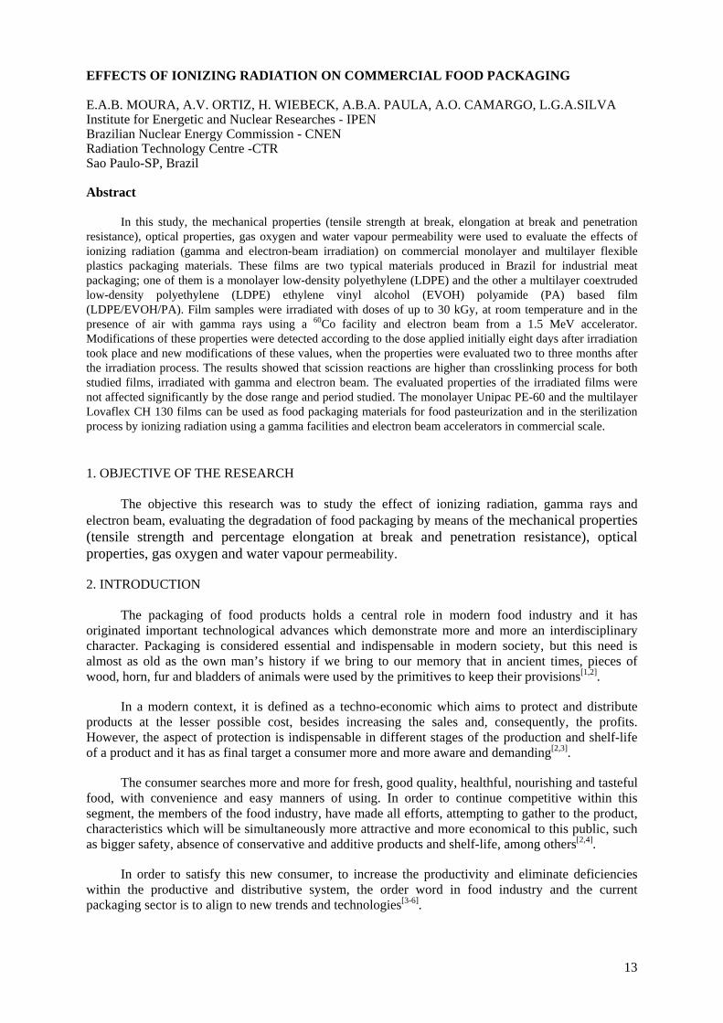
In this study, the mechanical properties (tensile strength at break, elongation at break and penetration resistance), optical properties, gas oxygen and water vapour permeability were used to evaluate the effects of ionizing radiation (gamma and electron-beam irradiation) on commercial monolayer and multilayer flexible plastics packaging materials. These films are two typical materials produced in Brazil for industrial meat packaging; one of them is a monolayer low-density polyethylene (LDPE) and the other a multilayer coextruded low-density polyethylene (LDPE) ethylene vinyl alcohol (EVOH) polyamide (PA) based film (LDPE/EVOH/PA). Film samples were irradiated with doses of up to 30 kGy, at room temperature and in the presence of air with gamma rays using a 60Co facility and electron beam from a 1.5 MeV accelerator. Modifications of these properties were detected according to the dose applied initially eight days after irradiation took place and new modifications of these values, when the properties were evaluated two to three months after the irradiation process. The results showed that scission reactions are higher than crosslinking process for both studied films, irradiated with gamma and electron beam. The evaluated properties of the irradiated films were not affected significantly by the dose range and period studied. The monolayer Unipac PE-60 and the multilayer Lovaflex CH 130 films can be used as food packaging materials for food pasteurization and in the sterilization process by ionizing radiation using a gamma facilities and electron beam accelerators in commercial scale. 1. OBJECTIVE OF THE RESEARCH
The objective this research was to study the effect of ionizing radiation, gamma rays and electron beam, evaluating the degradation of food packaging by means of the mechanical properties (tensile strength and percentage elongation at break and penetration resistance), optical properties, gas oxygen and water vapour permeability.
2. INTRODUCTION
The packaging of food products holds a central role in modern food industry and it has originated important technological advances which demonstrate more and more an interdisciplinary character. Packaging is considered essential and indispensable in modern society, but this need is almost as old as the own man’s history if we bring to our memory that in ancient times, pieces of wood, horn, fur and bladders of animals were used by the primitives to keep their provisions[1,2].
In a modern context, it is defined as a techno-economic which aims to protect and distribute products at the lesser possible cost, besides increasing the sales and, consequently, the profits. However, the aspect of protection is indispensable in different stages of the production and shelf-life of a product and it has as final target a consumer more and more aware and demanding[2,3].
The consumer searches more and more for fresh, good quality, healthful, nourishing and tasteful food, with convenience and easy manners of using. In order to continue competitive within this segment, the members of the food industry, have made all efforts, attempting to gather to the product, characteristics which will be simultaneously more attractive and more economical to this public, such as bigger safety, absence of conservative and additive products and shelf-life, among others[2,4].
In order to satisfy this new consumer, to increase the productivity and eliminate deficiencies within the productive and distributive system, the order word in food industry and the current packaging sector is to align to new trends and technologies[3-6].
13

Within this target, the processing by ionizing radiation for treatment and food preservation, the improvement of the packaging material and sterilization, is one of the technological innovations which has been gaining considerable prominence, especially in developing countries. These processes have become increasingly representative in the productive and servicing segments, from the supermarket sector to the cold storage plants, as well as the processing food and packaging industries[6-9].
The processing by ionizing radiation with radiation doses absorbed between 0.3-70 kGy is known as frozen pasteurization. Applied together with the traditional methods of treatment and preservation of foods, can reduce the number of pathogenic micro organisms in carneous products, their by-products and other kinds of food. The pasteurization by radiation is able to control the transmission of diseases derived from contaminated foods like salmonellas, and reduce the losses during the storage phases, processing, distribution and commercialization, leaving available for a world population in growth, healthful and safe food without changes in their nutritional and organoleptic properties[8-9].
Chicken meat has been irradiated for salmonella control in the United States since 1993 and, in December 1997, the Food and Drug Administration (FDA) approved irradiation of cooling or frozen red meat[8-10]. This measure renews the world interest in pasteurization for fresh meat radiation “in nature’ and pre-packed by-products, aiming the maintenance of the phytosanitary quality for long periods and the widening of the reaching of the distribution system of these perishable products. The irradiation of carneous products is recommended by the World Health Organization (WHO) and by the Commission of ‘Codex Alimentarius’. These products are irradiated and pre-packed, to avoid the microbial recontamination[8-10].
The packing industry has used the ionizing radiation to modify the chemical, mechanical, thermal properties, and the barriers of its final product, thus extending the application field and aggregating value. The crosslinking by radiation increases the thermal stability, the service temperature and the memory effect, improves the dimensional stability and the mechanical and barrier properties. In the United States, 90% of frozen poultries are kept in polyethylene films, crosslinked by radiation. Great attention has also been given to the application of ionizing radiation during the sterilization of flexible packaging for later storage of provisions in aseptic conditions[7-16].
The basic function of the pack is to keep the integrity of the product until its consumption, modifying the microenvironment around it, delaying deterioration reactions, preventing the humidity evaporation of the product and avoiding weight losses and alterations in the appearance, texture and flavour[1,2].
The radiation can cause structural changes in the packaging materials, altering their mechanical, chemical properties and their original barriers, among others. The material utilized for this processing, must present physical-chemical resistance to the radiation, must not suffer reduction of their characteristics of protection, neither transfer toxic substances, nor cause strange odour and flavour to the stored product[16,17].
The main goal of such work was to evaluate the effect of ionizing radiation on the properties of polyethylene monolayer flexible film, used for the storage of poultries (whole, carcasses and cuts), and coextruded multilayer film PA-co/EVOH/PE, used to pack products such as; frankfurters, pork sausages and sliced cold cuts, among others. Both films are produced by the national industry. The evaluated parameters were the mechanical, optical and barrier properties, the formation of volatile products.
The process of radio pasteurization of the carneous products is recommended by international organizations as United Nations Organization for Food and Agriculture Organization-FAO and World Health Organization (WHO) and it is widely used in several countries. In this process, the gamma ray or electron beam interact with the micro organisms, breaking chemical linking in molecules as DNA, damaging them and causing, as consequence, the micro organism inactivation. To avoid the recontamination, the products are irradiated pre-packed9.
14
As to the phytosanitary quality of the food, Brazil approved in January 2001, the ‘Technical Regulamentation for Irradiation of Food’10. However, the commercial irradiation of meat and by-products is not a reality yet. Possibly, it has been contributing for this, the shortage, in the national market, of adequate packs to the process and packaging material with corroborating physical-chemical resistance to the ionizing radiation.
3. MATERIALS AND METHODS
3.1. Materials
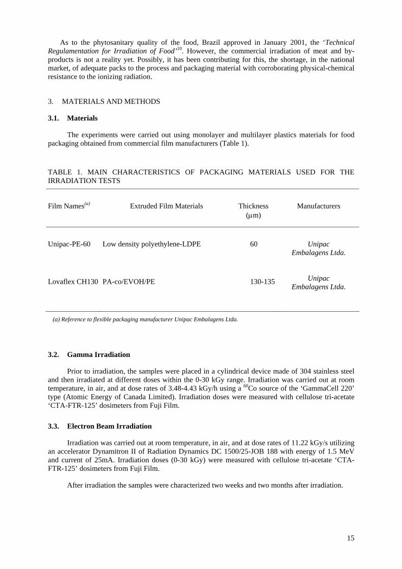
The experiments were carried out using monolayer and multilayer plastics materials for food packaging obtained from commercial film manufacturers (Table 1).
TABLE 1. MAIN CHARACTERISTICS OF PACKAGING MATERIALS USED FOR THE IRRADIATION TESTS
Film Names(a)
Extruded Film Materials
Thickness (μm)
Manufacturers
Unipac-PE-60
Lovaflex CH130
Low density polyethylene-LDPE
PA-co/EVOH/PE
60
130-135
Unipac Embalagens Ltda.
Unipac Embalagens Ltda.
(a) Reference to flexible packaging manufacturer Unipac Embalagens Ltda.
3.2. Gamma Irradiation
Prior to irradiation, the samples were placed in a cylindrical device made of 304 stainless steel and then irradiated at different doses within the 0-30 kGy range. Irradiation was carried out at room temperature, in air, and at dose rates of 3.48-4.43 kGy/h using a 60Co source of the ‘GammaCell 220’ type (Atomic Energy of Canada Limited). Irradiation doses were measured with cellulose tri-acetate ‘CTA-FTR-125’ dosimeters from Fuji Film.
3.3. Electron Beam Irradiation
Irradiation was carried out at room temperature, in air, and at dose rates of 11.22 kGy/s utilizing an accelerator Dynamitron II of Radiation Dynamics DC 1500/25-JOB 188 with energy of 1.5 MeV and current of 25mA. Irradiation doses (0-30 kGy) were measured with cellulose tri-acetate ‘CTA-FTR-125’ dosimeters from Fuji Film.
After irradiation the samples were characterized two weeks and two months after irradiation.
15
3.4. Characterization
Tensile strength at break-these tests were carried out on INSTRON mechanical equipment according to the specifications of ASTM D 882-91.
Elongation at break - these tests were carried out on INSTRON mechanical equipment according to the specifications of ASTM D 882-91.
Penetration resistance - these tests were carried out on INSTRON mechanical equipment according to the specifications of ASTM F 1306-90.
Optical properties - these tests were carried out on Shimadzu UV1601PC spectrophotometer according to the specifications of ASTM D 1746-92.
Oxygen gas permeability - these tests were carried out on OX-TRAN 2/20 of the Modern Controls Inc. according to the specifications of ASTM D 3985-81.
Water vapour permeability - these tests were carried out on Permatran-W Twin of the Modern Controls Inc. according to the specifications of ASTM F 372-99.
4. RESULTS AND DISCUSSION
4.1. Visual and sensorial aspects of the films after irradiation
4.1.1. Unipac-PE-60 film
The irradiated samples with gamma and electron beam in doses higher than 15 kGy presented a yellowish coloration and also emitted unpleasant. The intensity of such alterations increased with the irradiation dose.
4.1.2. Lovaflex CH-130 film
All the samples after irradiation presented, independently of the irradiation dose applied, a slight yellowish coloration and unpleasant odour of rancid, whose intensity increased with the irradiation dose.
However, it was observed that two weeks after the irradiation, the samples restored to their
original coloration and odour for both films studied.
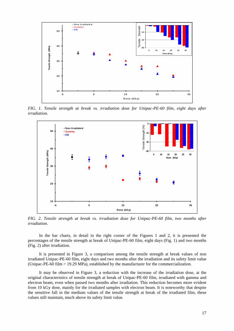
4.2. Mechanical tests 4.2.1. Tensile strength at break It is presented in Figures 1 and 2 the behaviour of the tensile strength at break, in terms of the irradiation dose for Unipac-PE-60 film, eight days after irradiation with gamma and electron beam.
It is observed in Figure 1 that Unipac-PE-60 film, eight days after irradiation presented:
1. Reduction in its tensile strength at break with the increase of the gamma irradiation dose. 2. Increase in its tensile strength at break for electron beam irradiation dose for 10 and 15 kGy
and reduction from 20 kGy.
It is observed in Figure 2 that the Unipac-PE-60 two months after irradiation with gamma and electron beam, presented a reduction in its tensile strength at break with the increase of the irradiation dose.
16
1 0
2 0
3 0
4 0
5 0
- 5 5 1 5 2 5 3
D o s e ( k G y )
Tens
ile S
tren
gth
(MPa
)
• N o n Ir r a d ia te d
FIG. 1. Tensile strength at break vs. irradiation dose for Unipac-PE-60 film, eight days after irradiation.
FIG. 2. Tensile strength at break vs. irradiation dose for Unipac-PE-60 film, two months after irradiation.
In the bar charts, in detail in the right corner of the Figures 1 and 2, it is presented the percentages of the tensile strength at break of Unipac-PE-60 film, eight days (Fig. 1) and two months (Fig. 2) after irradiation.
It is presented in Figure 3, a comparison among the tensile strength at break values of non
irradiated Unipac-PE-60 film, eight days and two months after the irradiation and its safety limit value (Unipac-PE-60 film > 19.29 MPa), established by the manufacturer for the commercialization.
It may be observed in Figure 3, a reduction with the increase of the irradiation dose, at the
original characteristics of tensile strength at break of Unipac-PE-60 film, irradiated with gamma and electron beam, even when passed two months after irradiation. This reduction becomes more evident from 10 kGy dose, mainly for the irradiated samples with electron beam. It is noteworthy that despite the sensitive fall in the medium values of the tensile strength at break of the irradiated film, these values still maintain, much above its safety limit value.
5
• E B• G a m m a
-46
-30
-14
5 10 15 20 25 30
Dose (kGy)
Res
istê
ncia
à tr
ação
(%)
gth
Tens
ile
Stre
n
10
20
30
40
50
-5 5 15 25 35
Dose (kGy)
Tens
ile S
tren
gth
(MPa
)
• Non Irradiated• Gamma• EB
-45
-30
-15
0
5 10 15 20 25 30Dose (kGy)
Res
istê
ncia
à tr
ação
(%)
Tens
ile S
treng
th (%
)
17

With regard to Lovaflex CH 130 film irradiated with gamma and electron beam, the tests of tensile strength at break, performed eight days after the irradiation (Fig. 4) presented:
1. Gains in their original tensile strength at break (non irradiated film) for the irradiated samples with gamma, in the irradiation doses up to 15 kGy (reaching about 10% for the dose of 10 kGy) and reduction of 2% in the dose of 20 kGy. In the doses of 25 and 30 kGy, the registered values were slightly higher than the non irradiated one;
2. Losses in the original tensile strength at break, during all interval of irradiation dose studied for the irradiated samples with electron beam.
In Figure 5 it is shown the behaviour of the tensile strength at break of Lovaflex CH 130 film,
two months after irradiation with gamma and electron beam.
0
10
20
30
40
0 5 10 15 20 25 30Dose (kGy)
Tens
ile S
treng
th (M
Pa)
Não irradiado Raios gama, 2 meses após Não irradiado, 2 meses após Feixe de elétrons Limite de segurança Feixe de elétrons, 2 meses após Raios gama
Non Irradiated Non Irradiated, afteer 2 months
Gamma, after 2 months EB
FIG. 3. Comparison between the values of tensile strength of non irradiated Unipac-PE-60 film, 8 days and 2 months after irradiation and its safety limit.
20
30
40
50
-5 5 15 25 3
Dose (kGy)
Tens
ile S
treng
ht (M
Pa)
• Non Irradiated
FIG. 4. Tensile strength at break vs. irradiation dose for Lovaflex CH 130 film, eight days after irradiation.
5
• EB• Gamma
-16
-8
0
8
5 10 15 20 25 30Dose (kGy)
Res
istê
ncia
à tr
ação
(%)
Tens
ileSt
reng
th
18

-16
-8
0
8
5 10 15 20 25 30Dose (kGy)
Res
istê
ncia
à tr
ação
(%)
20
30
40
50
-5 5 15 25 35Dose (kGy)
Tens
ile S
tren
gth
(MPa
)
• Non Irradiated
FIG. 5. Tensile strength at break vs. irradiation dose for Lovaflex CH 130 film, two months after irradiation.
With regard to the tensile strength at break tests performed in Lovaflex 130 film, two months after irradiation, it can be observed in the Fig. 5 that:
1. The tensile strength at break is higher than the non irradiated film for irradiation doses with gamma up to 15 kGy (2.5%) and for dose of 25 kGy. In the dose of 30 kGy its tensile strength at break is lower than the non irradiated about 2.5%;
2. In irradiations with electron beam, the tensile strength at break is higher than the original for irradiation doses of 5 (4.0%) and 15 kGy, and decreased with the increase of the irradiation dose in the interval of dose between 20 and 30 kGy, reaching its maximum reduction for the dose of 30 kGy about 10%.
The bar charts present in detail, in the right corner of the Fig. 4 and Fig. 5, the variations in
percentages of the tensile strength at break of Lovaflex 130 film, eight days (Fig. 4) and two months (Fig.5) after irradiation.
It is presented in Fig 6 a comparison between the values of the tensile strength at break of non
irradiated Lovaflex CH 130 film, eight days and two months after the irradiation, and its safety limit value (Lovaflex CH 130 > 19.14 MPa), established by the manufacturer for its commercialization.
In Figure 6 it can be observed that two months after the irradiation the tensile strength at break
for of Lovaflex CH 130 film irradiated with gamma, it did not present drastic changes, when compared to the original (non irradiated). It is clear that medium values of tensile strength at break get too close to their original values (non irradiated film) independently of the gamma irradiation dose applied, presenting slight modification for more or for less. In the irradiations with electron beam, two months after the irradiation, the medium values of tensile strength at break of the irradiated film presented higher deviations from the original, for some irradiation doses.
It is observed in the same Figure 6 a gain in tensile strength at break for the samples of the
irradiated Lovaflex CH 130 film with electron beam in the dose of 5 kGy (4%) and loss for irradiated samples with doses of 20 to 30 kGy (reduction in the order of 4 to 10%). Although irradiated Lovaflex CH 130 film with electron beam has performed a reduction of up to 10% on the value of its original tensile strength at break, it still maintains much above its safety limit value.
• Gamma• EB
Tens
ileS
treng
th(%
)
19
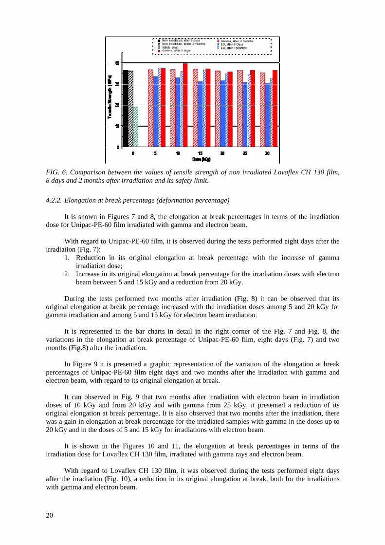
FIG. 6. Comparison between the values of tensile strength of non irradiated Lovaflex CH 130 film, 8 days and 2 months after irradiation and its safety limit.
4.2.2. Elongation at break percentage (deformation percentage) It is shown in Figures 7 and 8, the elongation at break percentages in terms of the irradiation dose for Unipac-PE-60 film irradiated with gamma and electron beam. With regard to Unipac-PE-60 film, it is observed during the tests performed eight days after the irradiation (Fig. 7):
1. Reduction in its original elongation at break percentage with the increase of gamma irradiation dose;
2. Increase in its original elongation at break percentage for the irradiation doses with electron beam between 5 and 15 kGy and a reduction from 20 kGy.
During the tests performed two months after irradiation (Fig. 8) it can be observed that its
original elongation at break percentage increased with the irradiation doses among 5 and 20 kGy for gamma irradiation and among 5 and 15 kGy for electron beam irradiation.
It is represented in the bar charts in detail in the right corner of the Fig. 7 and Fig. 8, the
variations in the elongation at break percentage of Unipac-PE-60 film, eight days (Fig. 7) and two months (Fig.8) after the irradiation.
In Figure 9 it is presented a graphic representation of the variation of the elongation at break
percentages of Unipac-PE-60 film eight days and two months after the irradiation with gamma and electron beam, with regard to its original elongation at break.
It can observed in Fig. 9 that two months after irradiation with electron beam in irradiation
doses of 10 kGy and from 20 kGy and with gamma from 25 kGy, it presented a reduction of its original elongation at break percentage. It is also observed that two months after the irradiation, there was a gain in elongation at break percentage for the irradiated samples with gamma in the doses up to 20 kGy and in the doses of 5 and 15 kGy for irradiations with electron beam.
It is shown in the Figures 10 and 11, the elongation at break percentages in terms of the
irradiation dose for Lovaflex CH 130 film, irradiated with gamma rays and electron beam. With regard to Lovaflex CH 130 film, it was observed during the tests performed eight days
after the irradiation (Fig. 10), a reduction in its original elongation at break, both for the irradiations with gamma and electron beam.
20
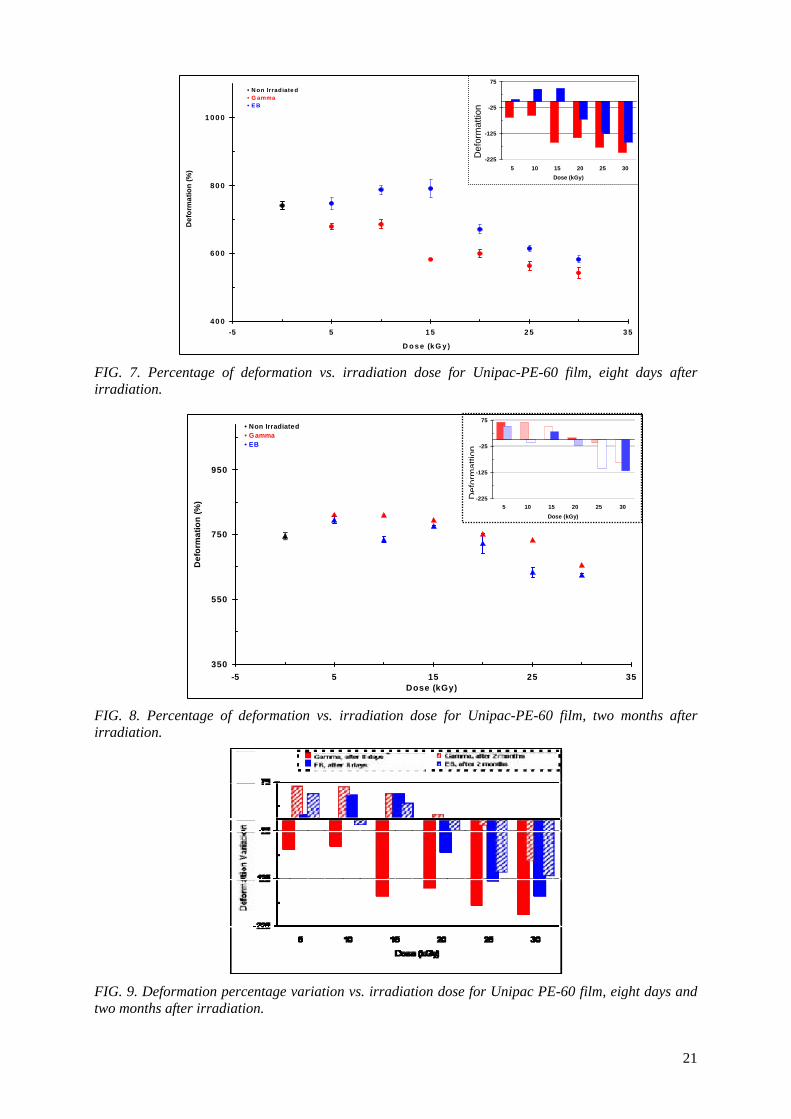
4 0 0
6 0 0
8 0 0
1 00 0
-5 5 1 5 2 5 3
D o s e (k G y )
Def
orm
atio
n (%
)
• N on Irradiate d
FIG. 7. Percentage of deformation vs. irradiation dose for Unipac-PE-60 film, eight days after irradiation.
FIG. 8. Percentage of deformation vs. irradiation dose for Unipac-PE-60 film, two months after irradiation.
FIG. 9. Deformation percentage variation vs. irradiation dose for Unipac PE-60 film, eight days and two months after irradiation.
5
• E B• G amma
-225
-125
-25
75
5 10 15 20 25 30Dose (kGy)
Varia
ção
da %
de
defo
rmaç
ãoD
efor
mat
tion
350
550
750
950
-5 5 15 25 3Dose (kGy)
Def
orm
atio
n (%
)
• Non Irradiated
5
• EB• Gamma
-225
-125
-25
75
5 10 15 20 25 30Dose (kGy)
Varia
ção
da %
de
defo
rmaç
ãoD
efor
mat
tion
21
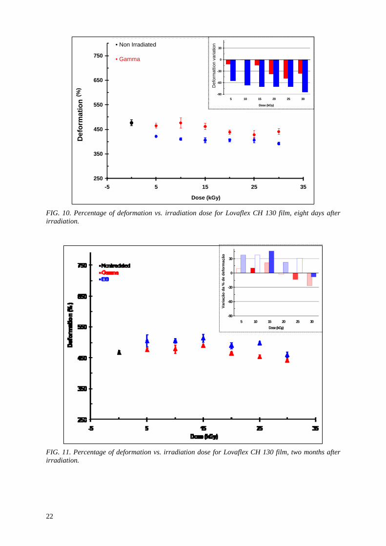
250
350
450
550
650
750
-5 5 15 25 35
Dose (kGy)
Def
orm
ação
(%
)
Não irradiado Feixes de elétrons, 8 dias após
FIG. 10. Percentage of deformation vs. irradiation dose for Lovaflex CH 130 film, eight days after irradiation.
FIG. 11. Percentage of deformation vs. irradiation dose for Lovaflex CH 130 film, two months after irradiation.
Raios gama,8 dias após
-90
-60
-30
0
30
5 10 15 20 25 30
Dose (kGy)
Varia
ção
da %
de
defo
rmaç
ão• Non Irradiated
Def
orm
attio
n va
riatio
n
• Gamma
Def
orm
atio
n
-90
-60
-30
0
30
5 10 15 20 25 30Dose (kGy)
Varia
ção
da %
de
defo
rmaç
ão
22
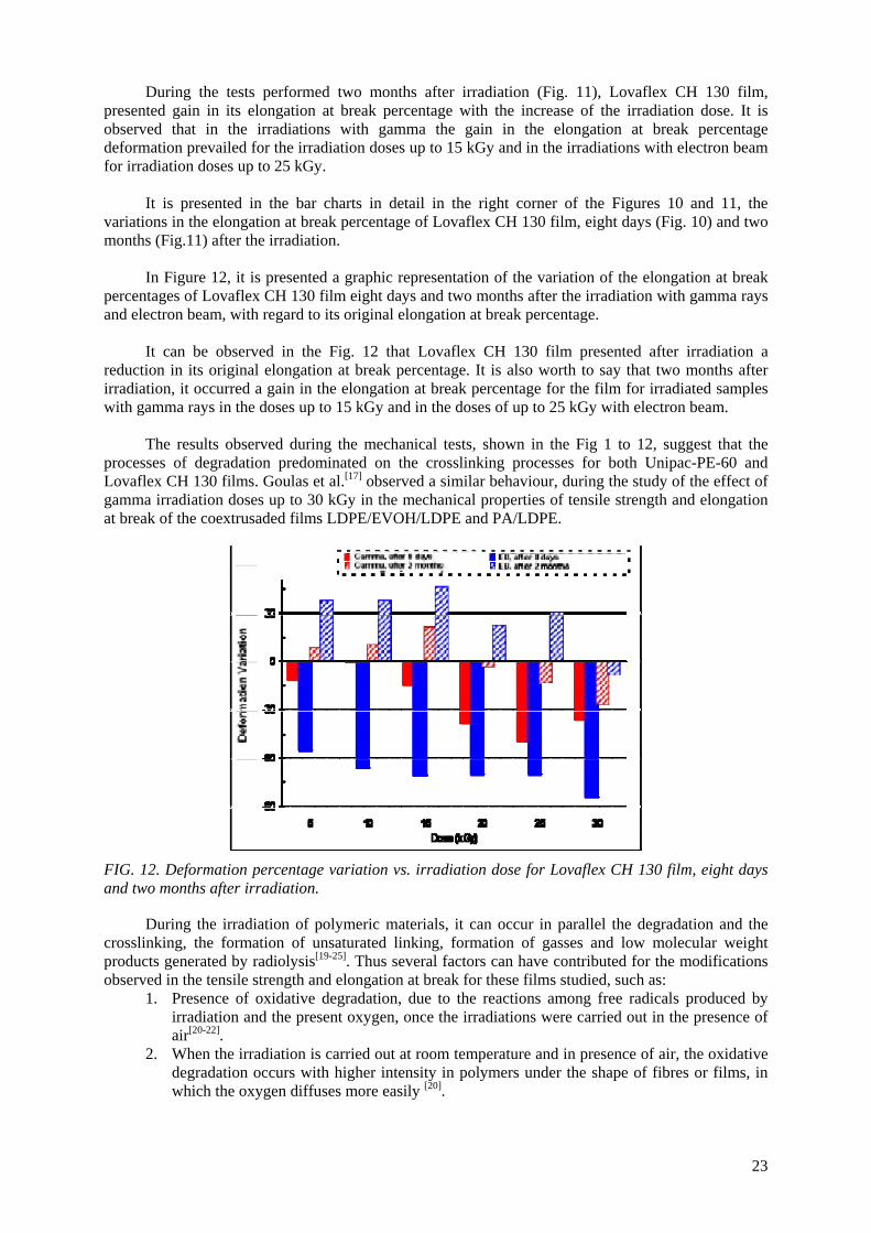
During the tests performed two months after irradiation (Fig. 11), Lovaflex CH 130 film, presented gain in its elongation at break percentage with the increase of the irradiation dose. It is observed that in the irradiations with gamma the gain in the elongation at break percentage deformation prevailed for the irradiation doses up to 15 kGy and in the irradiations with electron beam for irradiation doses up to 25 kGy.
It is presented in the bar charts in detail in the right corner of the Figures 10 and 11, the
variations in the elongation at break percentage of Lovaflex CH 130 film, eight days (Fig. 10) and two months (Fig.11) after the irradiation.
In Figure 12, it is presented a graphic representation of the variation of the elongation at break
percentages of Lovaflex CH 130 film eight days and two months after the irradiation with gamma rays and electron beam, with regard to its original elongation at break percentage.
It can be observed in the Fig. 12 that Lovaflex CH 130 film presented after irradiation a
reduction in its original elongation at break percentage. It is also worth to say that two months after irradiation, it occurred a gain in the elongation at break percentage for the film for irradiated samples with gamma rays in the doses up to 15 kGy and in the doses of up to 25 kGy with electron beam.
The results observed during the mechanical tests, shown in the Fig 1 to 12, suggest that the
processes of degradation predominated on the crosslinking processes for both Unipac-PE-60 and Lovaflex CH 130 films. Goulas et al.[17] observed a similar behaviour, during the study of the effect of gamma irradiation doses up to 30 kGy in the mechanical properties of tensile strength and elongation at break of the coextrusaded films LDPE/EVOH/LDPE and PA/LDPE.
FIG. 12. Deformation percentage variation vs. irradiation dose for Lovaflex CH 130 film, eight days and two months after irradiation.
During the irradiation of polymeric materials, it can occur in parallel the degradation and the crosslinking, the formation of unsaturated linking, formation of gasses and low molecular weight products generated by radiolysis[19-25]. Thus several factors can have contributed for the modifications observed in the tensile strength and elongation at break for these films studied, such as:
1. Presence of oxidative degradation, due to the reactions among free radicals produced by irradiation and the present oxygen, once the irradiations were carried out in the presence of air[20-22].
2. When the irradiation is carried out at room temperature and in presence of air, the oxidative degradation occurs with higher intensity in polymers under the shape of fibres or films, in which the oxygen diffuses more easily [20].
23
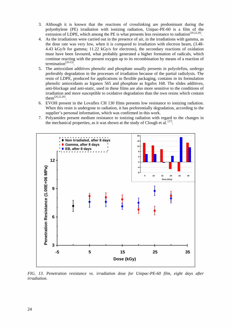
3. Although it is known that the reactions of crosslinking are predominant during the polyethylene (PE) irradiation with ionizing radiation, Unipac-PE-60 is a film of the extrusion of LDPE, which among the PE is what presents less resistance to radiation[20,22,26].
4. As the irradiations were carried out in the presence of air, in the irradiations with gamma, as the dose rate was very low, when it is compared to irradiation with electron beam, (3.48-4.43 kGy/h for gamma; 11.22 kGy/s for electrons), the secondary reactions of oxidation must have been favoured, what probably generated a higher formation of radicals, which continue reacting with the present oxygen up to its recombination by means of a reaction of termination[20-23].
5. The antioxidant additives phenolic and phosphate usually presents in polyolefins, undergo preferably degradation in the processes of irradiation because of the partial radiolysis. The resin of LDPE, produced for applications in flexible packaging, contains in its formulation phenolic antioxidants as Irganox 565 and phosphate as Irgafos 168. The slides additives, anti-blockage and anti-static, used in these films are also more sensitive to the conditions of irradiation and more susceptible to oxidative degradation than the own resins which contain them[20,22,26].
6. EVOH present in the Lovaflex CH 130 films presents low resistance to ionizing radiation. When this resin is undergone to radiation, it has preferentially degradation, according to the supplier’s personal information, which was confirmed in this work.
7. Polyamides present medium resistance to ionizing radiation with regard to the changes in the mechanical properties, as it was shown at the study of Clough et al. [27].
FIG. 13. Penetration resistance vs. irradiation dose for Unipac-PE-60 film, eight days after irradiation.
3
6
9
12
-5 5 15 25 35 Dose (kGy)
Pene
trat
ion
Res
ista
nce
(1.0
0E+0
6 M
Pa)
-8
-4
0
4
8
12
16
20
5 10 15 20 25 30 Dose (kGy)
Non Irradiated, after 8 days Gamma, after 8 days EB, after 8 days
24
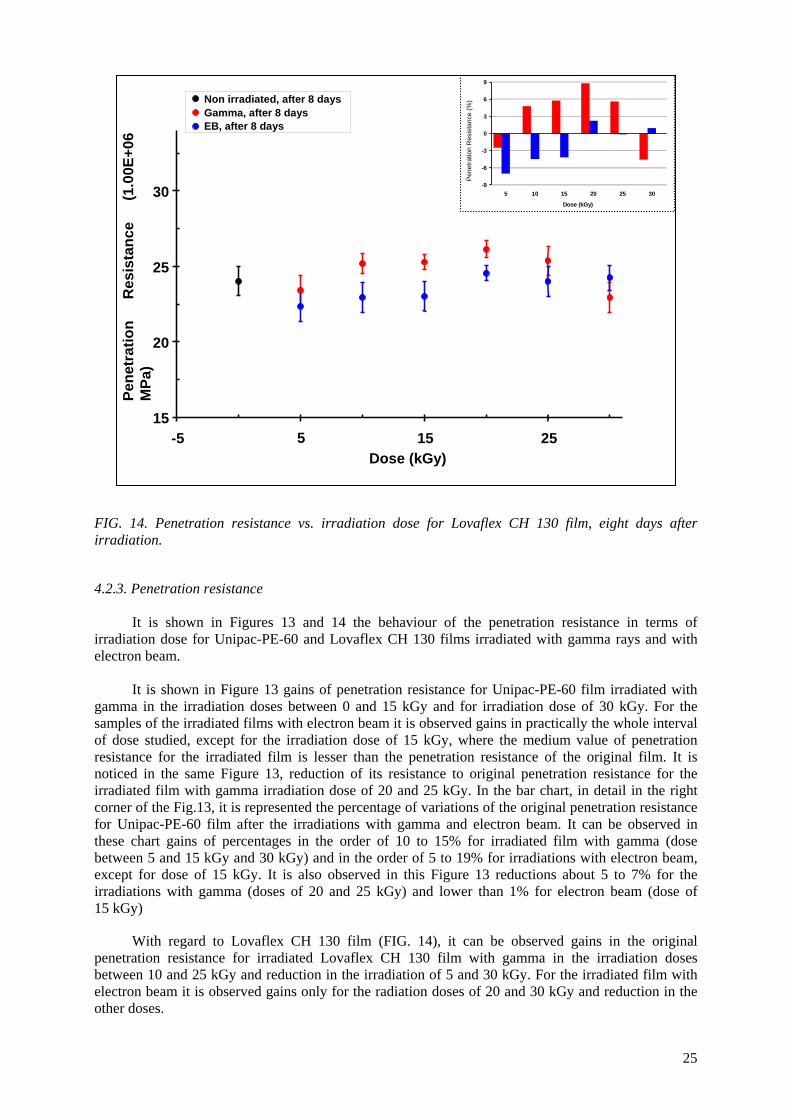
-9
-6
-3
0
3
6
9
5 10 15 20 25 30
Dose (kGy)
Res
istê
ncia
à p
erfu
raçã
o (%
)
FIG. 14. Penetration resistance vs. irradiation dose for Lovaflex CH 130 film, eight days after irradiation.
4.2.3. Penetration resistance It is shown in Figures 13 and 14 the behaviour of the penetration resistance in terms of
irradiation dose for Unipac-PE-60 and Lovaflex CH 130 films irradiated with gamma rays and with electron beam.
It is shown in Figure 13 gains of penetration resistance for Unipac-PE-60 film irradiated with
gamma in the irradiation doses between 0 and 15 kGy and for irradiation dose of 30 kGy. For the samples of the irradiated films with electron beam it is observed gains in practically the whole interval of dose studied, except for the irradiation dose of 15 kGy, where the medium value of penetration resistance for the irradiated film is lesser than the penetration resistance of the original film. It is noticed in the same Figure 13, reduction of its resistance to original penetration resistance for the irradiated film with gamma irradiation dose of 20 and 25 kGy. In the bar chart, in detail in the right corner of the Fig.13, it is represented the percentage of variations of the original penetration resistance for Unipac-PE-60 film after the irradiations with gamma and electron beam. It can be observed in these chart gains of percentages in the order of 10 to 15% for irradiated film with gamma (dose between 5 and 15 kGy and 30 kGy) and in the order of 5 to 19% for irradiations with electron beam, except for dose of 15 kGy. It is also observed in this Figure 13 reductions about 5 to 7% for the irradiations with gamma (doses of 20 and 25 kGy) and lower than 1% for electron beam (dose of 15 kGy)
With regard to Lovaflex CH 130 film (FIG. 14), it can be observed gains in the original penetration resistance for irradiated Lovaflex CH 130 film with gamma in the irradiation doses between 10 and 25 kGy and reduction in the irradiation of 5 and 30 kGy. For the irradiated film with electron beam it is observed gains only for the radiation doses of 20 and 30 kGy and reduction in the other doses.
Pene
tratio
n R
esis
tanc
e (%
)
15
20
25
30
-5 5 15 25Dose (kGy)
Pene
trat
ion
Res
ista
nce
(1.0
0E+0
6M
Pa)
Non irradiated, after 8 days Gamma, after 8 days EB, after 8 days
25
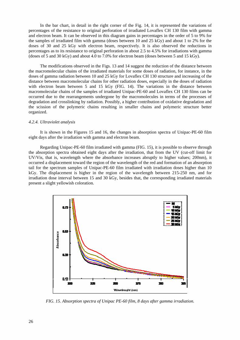
In the bar chart, in detail in the right corner of the Fig. 14, it is represented the variations of percentages of the resistance to original perforation of irradiated Lovaflex CH 130 film with gamma and electron beam. It can be observed in this diagram gains in percentages in the order of 5 to 9% for the samples of irradiated film with gamma (doses between 10 and 25 kGy) and about 1 to 2% for the doses of 30 and 25 kGy with electron beam, respectively. It is also observed the reductions in percentages as to its resistance to original perforation in about 2.5 to 4.5% for irradiations with gamma (doses of 5 and 30 kGy) and about 4.0 to 7.0% for electron beam (doses between 5 and 15 kGy).
The modifications observed in the Figs. 13 and 14 suggest the reduction of the distance between the macromolecular chains of the irradiated materials for some doses of radiation, for instance, in the doses of gamma radiation between 10 and 25 kGy for Lovaflex CH 130 structure and increasing of the distance between macromolecular chains for other radiation doses, especially in the doses of radiation with electron beam between 5 and 15 kGy (FIG. 14). The variations in the distance between macromolecular chains of the samples of irradiated Unipac-PE-60 and Lovaflex CH 130 films can be occurred due to the rearrangements undergone by the macromolecules in terms of the processes of degradation and crosslinking by radiation. Possibly, a higher contribution of oxidative degradation and the scission of the polymeric chains resulting in smaller chains and polymeric structure better organized.
4.2.4. Ultraviolet analysis
It is shown in the Figures 15 and 16, the changes in absorption spectra of Unipac-PE-60 film eight days after the irradiation with gamma and electron beam.
Regarding Unipac-PE-60 film irradiated with gamma (FIG. 15), it is possible to observe through the absorption spectra obtained eight days after the irradiation, that from the UV (cut-off limit for UV/Vis, that is, wavelength where the absorbance increases abruptly to higher values; 200nm), it occurred a displacement toward the region of the wavelength of the red and formation of an absorption tail for the spectrum samples of Unipac-PE-60 film irradiated with irradiation doses higher than 10 kGy. The displacement is higher in the region of the wavelength between 215-250 nm, and for irradiation dose interval between 15 and 30 kGy, besides that, the corresponding irradiated materials present a slight yellowish coloration.
FIG. 15. Absorption spectra of Unipac PE-60 film, 8 days after gamma irradiation.
26
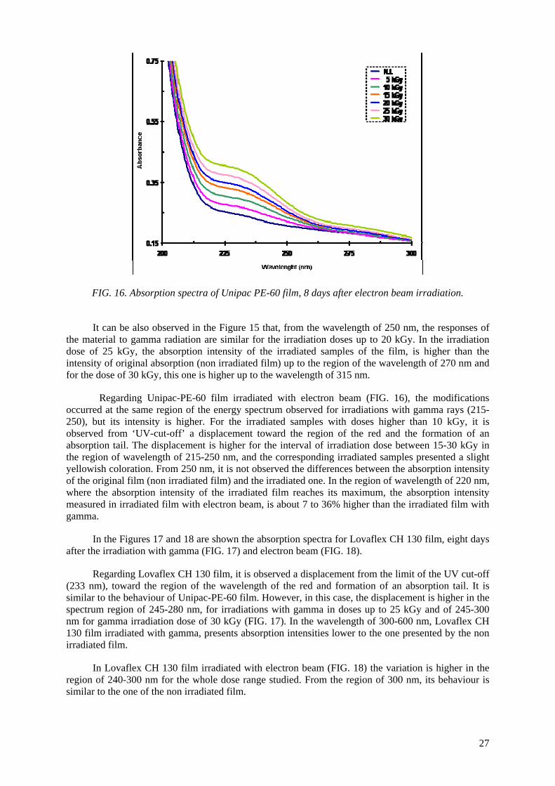
FIG. 16. Absorption spectra of Unipac PE-60 film, 8 days after electron beam irradiation.
It can be also observed in the Figure 15 that, from the wavelength of 250 nm, the responses of the material to gamma radiation are similar for the irradiation doses up to 20 kGy. In the irradiation dose of 25 kGy, the absorption intensity of the irradiated samples of the film, is higher than the intensity of original absorption (non irradiated film) up to the region of the wavelength of 270 nm and for the dose of 30 kGy, this one is higher up to the wavelength of 315 nm.
Regarding Unipac-PE-60 film irradiated with electron beam (FIG. 16), the modifications occurred at the same region of the energy spectrum observed for irradiations with gamma rays (215-250), but its intensity is higher. For the irradiated samples with doses higher than 10 kGy, it is observed from ‘UV-cut-off’ a displacement toward the region of the red and the formation of an absorption tail. The displacement is higher for the interval of irradiation dose between 15-30 kGy in the region of wavelength of 215-250 nm, and the corresponding irradiated samples presented a slight yellowish coloration. From 250 nm, it is not observed the differences between the absorption intensity of the original film (non irradiated film) and the irradiated one. In the region of wavelength of 220 nm, where the absorption intensity of the irradiated film reaches its maximum, the absorption intensity measured in irradiated film with electron beam, is about 7 to 36% higher than the irradiated film with gamma.
In the Figures 17 and 18 are shown the absorption spectra for Lovaflex CH 130 film, eight days after the irradiation with gamma (FIG. 17) and electron beam (FIG. 18).
Regarding Lovaflex CH 130 film, it is observed a displacement from the limit of the UV cut-off (233 nm), toward the region of the wavelength of the red and formation of an absorption tail. It is similar to the behaviour of Unipac-PE-60 film. However, in this case, the displacement is higher in the spectrum region of 245-280 nm, for irradiations with gamma in doses up to 25 kGy and of 245-300 nm for gamma irradiation dose of 30 kGy (FIG. 17). In the wavelength of 300-600 nm, Lovaflex CH 130 film irradiated with gamma, presents absorption intensities lower to the one presented by the non irradiated film.
In Lovaflex CH 130 film irradiated with electron beam (FIG. 18) the variation is higher in the region of 240-300 nm for the whole dose range studied. From the region of 300 nm, its behaviour is similar to the one of the non irradiated film.
27
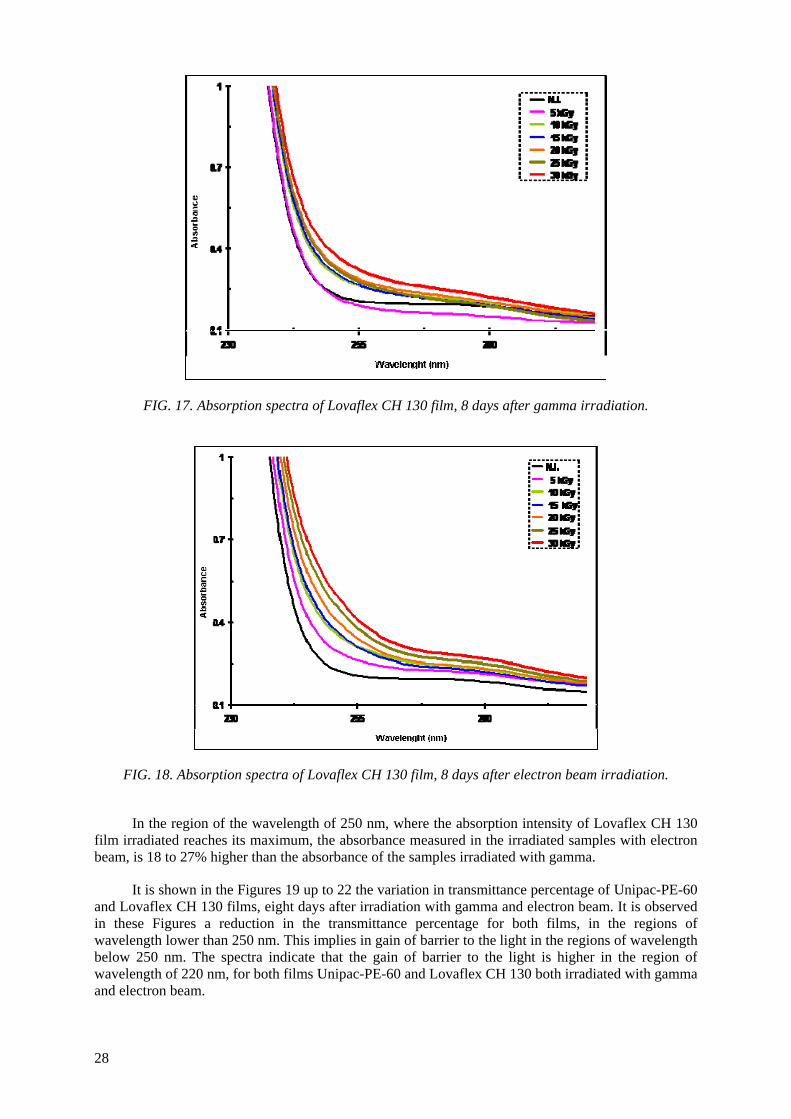
FIG. 17. Absorption spectra of Lovaflex CH 130 film, 8 days after gamma irradiation.
FIG. 18. Absorption spectra of Lovaflex CH 130 film, 8 days after electron beam irradiation.
In the region of the wavelength of 250 nm, where the absorption intensity of Lovaflex CH 130 film irradiated reaches its maximum, the absorbance measured in the irradiated samples with electron beam, is 18 to 27% higher than the absorbance of the samples irradiated with gamma.
It is shown in the Figures 19 up to 22 the variation in transmittance percentage of Unipac-PE-60 and Lovaflex CH 130 films, eight days after irradiation with gamma and electron beam. It is observed in these Figures a reduction in the transmittance percentage for both films, in the regions of wavelength lower than 250 nm. This implies in gain of barrier to the light in the regions of wavelength below 250 nm. The spectra indicate that the gain of barrier to the light is higher in the region of wavelength of 220 nm, for both films Unipac-PE-60 and Lovaflex CH 130 both irradiated with gamma and electron beam.
28
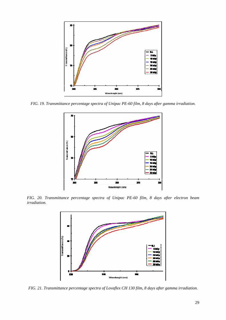
FIG. 19. Transmittance percentage spectra of Unipac PE-60 film, 8 days after gamma irradiation.
FIG. 20. Transmittance percentage spectra of Unipac PE-60 film, 8 days after electron beam irradiation.
FIG. 21. Transmittance percentage spectra of Lovaflex CH 130 film, 8 days after gamma irradiation.
29

FIG. 22. Transmittance percentage spectra of Lovaflex CH 130 film, 8 days after electron beam irradiation.
The behaviour of Unipac-PE-60 and Lovaflex films irradiated with gamma or electron beam, observed from FIG. 15 up to FIG. 22, indicate that the effect of ionizing radiation on its optical properties is higher in the low wavelengths, mainly in the region of UV radiation (190-400 nm). The changes in the original optic properties of these films observed after irradiation with gamma and electron beam can occur due to the unsaturations and the hydroxyl and carbonylic compounds, produced during the irradiation process in the oxygen presence. In both films it is observed the formation of oxidation products. These results indicate the oxidative degradation of these films after irradiation.
4.4. Water vapour permeability
It is shown in the Figures 23 and 24 the water vapour permeability in terms of the gamma irradiation dose for Unipac-PE-60 film, irradiated with gamma and electron beam, eight days and three months after the irradiation.
These results indicate a sensitive gain of barrier to water vapour for Unipac-PE-60 film, eight days after the irradiation with gamma and electron beam, when compared the rate of water vapour permeability to original (non irradiated film). The variations in percentages on the rate of water vapour permeability for the original Unipac-PE-60 film are represented in the bar chart, in detail in the right corner of the Fig. 23.
With regard to the water vapour permeability of Unipac-PE-60 film three months after the irradiation with gamma and electron beam (Fig. 24), it is possible to observe a sensitive reduction in its water vapour permeability rate, for the irradiated samples with electron beam in the doses of 10 and 30 kGy (about 2 and 3%, respectively), when compared with to the value of the water vapour permeability rate of the original film, measured at the same time (graphic area indicated by the green dotted line, Fig. 24).
The results presented in the figure 24 indicate a sensitive gain of barrier to the water vapour for Unipac-PE-60 film, three months after the irradiation with electron beam in the doses of 10 and 30 kGy and losses of barrier for both irradiated film with electron beam for other doses, and also for the irradiation with gamma during the whole interval of dose studied.
30

-20
-10
0
5 10 15 20 25 30Dose (kGy)
Perm
eabi
lidad
e ao
H2O
vapo
r (%
)
3
5
7
9
11
0 10 20 30
Dose (kGy)
Per
mea
bilid
ade
ao H
2O
vapo
r (g/
m2/2
4h
oras
)
Não irradiado Feixe de elétrons, oito dias após Raios gama, oito dias após
H2O
vapo
r Per
mea
bilit
y (g
/m²/2
4 ho
urs)
Non Irradiated Gamma, after 8 days EB, after 8 days
H2O
vapo
r Per
mea
bilit
y (%
) FIG. 23. Water vapour permeability rate vs. irradiation dose for Unipac-PE-60 film, eight days after irradiation.
FIG. 24. Water vapour permeability rate vs. irradiation dose for Unipac-PE-60 film, three months after irradiation.
With regard to Unipac-PE-60 film, the results of the tests carried out eight days after the irradiation (Fig. 23) presented reduction at the water vapour permeability of the irradiated film with gamma and electron beam, when it was compared to the maximum and minimum value of the rate of water vapour permeability of the original film, measured at the same time, which is between 7.2 and 8.2 g/m2/24 hours (graphic area indicated by the dotted lines, Fig. 23).
31
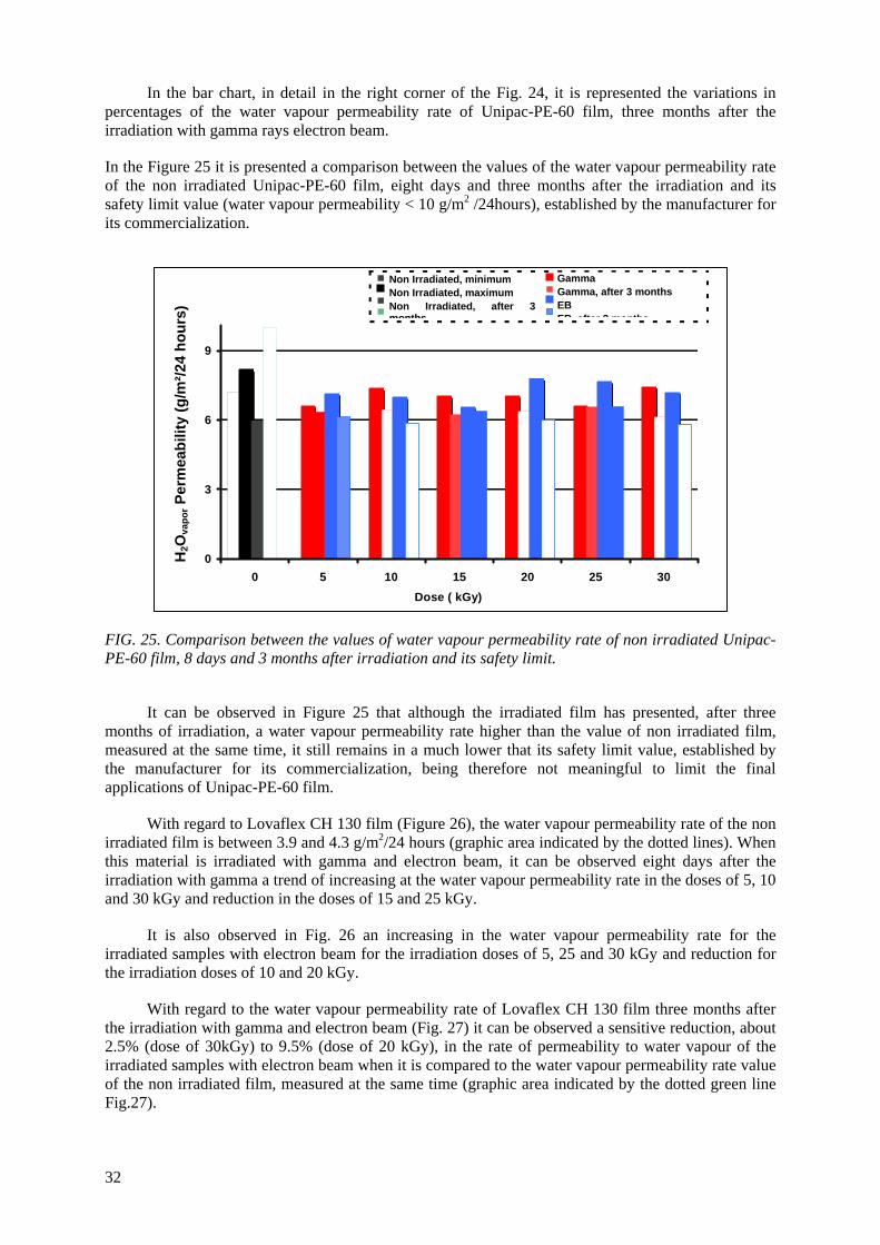
In the bar chart, in detail in the right corner of the Fig. 24, it is represented the variations in percentages of the water vapour permeability rate of Unipac-PE-60 film, three months after the irradiation with gamma rays electron beam.
In the Figure 25 it is presented a comparison between the values of the water vapour permeability rate of the non irradiated Unipac-PE-60 film, eight days and three months after the irradiation and its safety limit value (water vapour permeability < 10 g/m2 /24hours), established by the manufacturer for its commercialization.
0
3
6
9
0 5 10 15 20 25 30Dose ( kGy)
Perm
eabi
lidad
e ao
H2O
vapo
r (g/
m2 /2
4hor
as)
Não irradiado, valor mínimo Raios gama Não irradiado, valor máximo
FIG. 25. Comparison between the values of water vapour permeability rate of non irradiated Unipac-PE-60 film, 8 days and 3 months after irradiation and its safety limit.
It can be observed in Figure 25 that although the irradiated film has presented, after three months of irradiation, a water vapour permeability rate higher than the value of non irradiated film, measured at the same time, it still remains in a much lower that its safety limit value, established by the manufacturer for its commercialization, being therefore not meaningful to limit the final applications of Unipac-PE-60 film.
With regard to Lovaflex CH 130 film (Figure 26), the water vapour permeability rate of the non irradiated film is between 3.9 and 4.3 g/m2/24 hours (graphic area indicated by the dotted lines). When this material is irradiated with gamma and electron beam, it can be observed eight days after the irradiation with gamma a trend of increasing at the water vapour permeability rate in the doses of 5, 10 and 30 kGy and reduction in the doses of 15 and 25 kGy.
It is also observed in Fig. 26 an increasing in the water vapour permeability rate for the irradiated samples with electron beam for the irradiation doses of 5, 25 and 30 kGy and reduction for the irradiation doses of 10 and 20 kGy.
With regard to the water vapour permeability rate of Lovaflex CH 130 film three months after the irradiation with gamma and electron beam (Fig. 27) it can be observed a sensitive reduction, about 2.5% (dose of 30kGy) to 9.5% (dose of 20 kGy), in the rate of permeability to water vapour of the irradiated samples with electron beam when it is compared to the water vapour permeability rate value of the non irradiated film, measured at the same time (graphic area indicated by the dotted green line Fig.27).
Raios gama, 3 meses após Não irradiado, 3 meses após Feixe de elétrons Limite máximo elétrons, meses apósFeixe de 3
GammaGamma, after 3 months EB
Non Irradiated, minimumNon Irradiated, maximum
rradiated, after 3 Non Imont
H2O
vapo
r Per
mea
bilit
y (g
/m²/2
4 ho
urs)
hs EB fte 3 thsa r mon
32
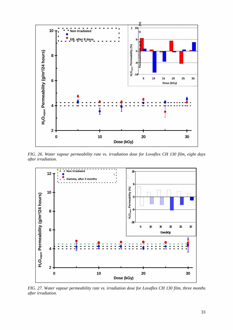
FIG. 26. Water vapour permeability rate vs. irradiation dose for Lovaflex CH 130 film, eight days after irradiation.
FIG. 27. Water vapour permeability rate vs. irradiation dose for Lovaflex CH 130 film, three months after irradiation.
-18
-9
0
9
18
5 10 15 20 25 30
Dose (kGy)
Perm
eabi
lidad
e ao
H2O
vapo
r (%
)
2
4
6
8
10
12
0 10 20Dose (kGy)
Perm
eabi
lidad
e ao
H2O
vapo
r (g/
m2 /2
4hor
as)
30
Não irradiado Feixes de elétrons, 3 meses após Raios gama, 3 meses após Não irradiado, 3 meses após
H2O
vapo
r Per
mea
bilit
y (g
/m²/2
4 ho
urs)
Non Irradiated
Gamma, after 3 months
H2O
vapo
r Per
mea
bilit
y (%
) 2
4
6
8
10
0 10 20 30Dose (kGy)
Perm
eabi
lidad
e ao
H2O
vapo
r (g/
m2 /2
4hor
as)
Não irradiado Feixes de elétrons, 8 dias após Raios gama, oito dias após
-18
-9
0
9
18
5 10 15 20 25 30Dose (kGy)
Perm
eabi
lidad
e ao
H
2
O vapo
r (%)
Non Irradiated
EB, after 8 days
H2O
vapo
r Per
mea
bilit
y (%
)
Per
mea
bilit
y (g
/m²/2
4 ho
urs)
H
2Ova
por
33
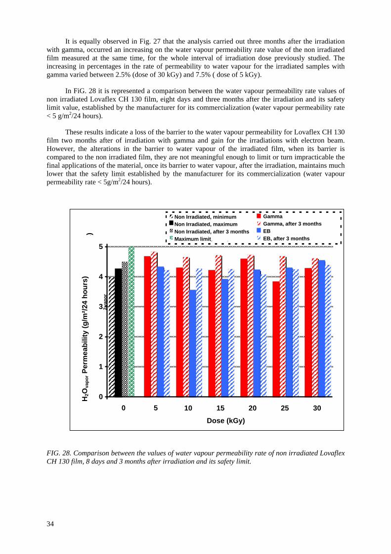
It is equally observed in Fig. 27 that the analysis carried out three months after the irradiation with gamma, occurred an increasing on the water vapour permeability rate value of the non irradiated film measured at the same time, for the whole interval of irradiation dose previously studied. The increasing in percentages in the rate of permeability to water vapour for the irradiated samples with gamma varied between 2.5% (dose of 30 kGy) and 7.5% ( dose of 5 kGy).
In FiG. 28 it is represented a comparison between the water vapour permeability rate values of non irradiated Lovaflex CH 130 film, eight days and three months after the irradiation and its safety limit value, established by the manufacturer for its commercialization (water vapour permeability rate < 5 g/m2/24 hours).
These results indicate a loss of the barrier to the water vapour permeability for Lovaflex CH 130 film two months after of irradiation with gamma and gain for the irradiations with electron beam. However, the alterations in the barrier to water vapour of the irradiated film, when its barrier is compared to the non irradiated film, they are not meaningful enough to limit or turn impracticable the final applications of the material, once its barrier to water vapour, after the irradiation, maintains much lower that the safety limit established by the manufacturer for its commercialization (water vapour permeability rate < 5g/m2/24 hours).
0
1
2
3
4
5
0 5 10 15 20 25 30
Dose (kGy)
Perm
eabi
lidad
e ao
H 2 O
vapo
r
(g/m
2
/ 24h
oras
)
Não irradiado, valor mín. Raios gama Não irradiado, valor máximo
FIG. 28. Comparison between the values of water vapour permeability rate of non irradiated Lovaflex CH 130 film, 8 days and 3 months after irradiation and its safety limit.
Raios gama, 3 meses Não s irradiado, 3 meses apó Feixes de elétrons L urançaimite de seg s, 3 sFeixes de elétron
Gamma Gamma, after 3 months EB EB, after 3 months
Non Irradiated, minimum Non Irradiated, maximum Non Irradiated, after 3 months Maximum limit
H2O
vapo
r Per
mea
bilit
y (g
/m²/2
4 ho
urs)
34
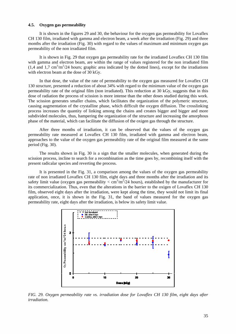
4.5. Oxygen gas permeability
It is shown in the figures 29 and 30, the behaviour for the oxygen gas permeability for Lovaflex CH 130 film, irradiated with gamma and electron beam, a week after the irradiation (Fig. 29) and three months after the irradiation (Fig. 30) with regard to the values of maximum and minimum oxygen gas permeability of the non irradiated film.
It is shown in Fig. 29 that oxygen gas permeability rate for the irradiated Lovaflex CH 130 film with gamma and electron beam, are within the range of values registered for the non irradiated film (1,4 and 1,7 cm3/m2/24 hours; graphic area indicated by the dotted lines), except for the irradiations with electron beam at the dose of 30 kGy.
In that dose, the value of the rate of permeability to the oxygen gas measured for Lovaflex CH 130 structure, presented a reduction of about 34% with regard to the minimum value of the oxygen gas permeability rate of the original film (non irradiated). This reduction at 30 kGy, suggests that in this dose of radiation the process of scission is more intense than the other doses studied during this work. The scission generates smaller chains, which facilitates the organization of the polymeric structure, causing augmentation of the crystalline phase, which difficult the oxygen diffusion. The crosslinking process increases the quantity of linking among the chains and creates bigger and bigger and more subdivided molecules, thus, hampering the organization of the structure and increasing the amorphous phase of the material, which can facilitate the diffusion of the oxigen gas through the structure.
After three months of irradiation, it can be observed that the values of the oxygen gas permeability rate measured at Lovaflex CH 130 film, irradiated with gamma and electron beam, approaches to the value of the oxygen gas permeability rate of the original film measured at the same period (Fig. 30).
The results shown in Fig. 30 is a sign that the smaller molecules, when generated during the scission process, incline to search for a recombination as the time goes by, recombining itself with the present radicalar species and reverting the process.
It is presented in the Fig. 31, a comparison among the values of the oxygen gas permeability rate of non irradiated Lovaflex CH 130 film, eight days and three months after the irradiation and its safety limit value (oxygen gas permeability < cm3/m2/24 hours), established by the manufacturer for its commercialization. Thus, even that the alterations in the barrier to the oxigen of Lovaflex CH 130 film, observed eight days after the irradiation, were kept along the time, they would not limit its final application, once, it is shown in the Fig. 31, the band of values measured for the oxygen gas permeability rate, eight days after the irradiation, is below its safety limit value.
FIG. 29. Oxygen permeability rate vs. irradiation dose for Lovaflex CH 130 film, eight days after irradiation.
35
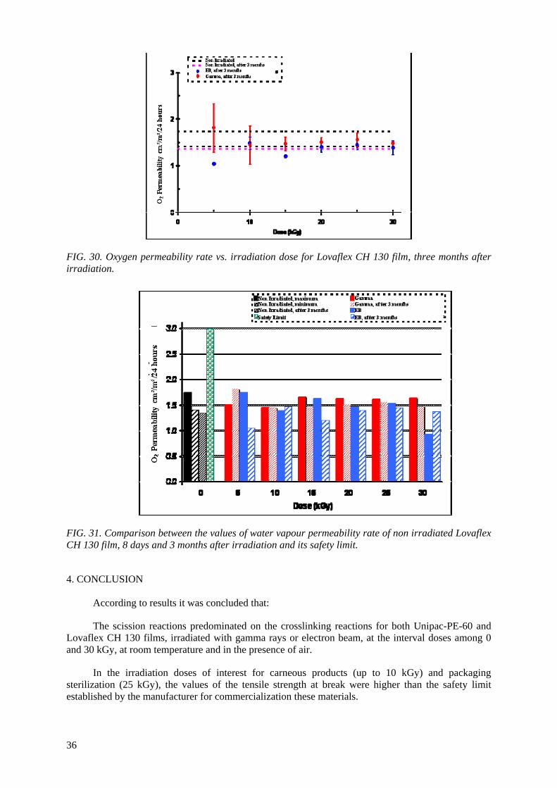
FIG. 30. Oxygen permeability rate vs. irradiation dose for Lovaflex CH 130 film, three months after irradiation.
FIG. 31. Comparison between the values of water vapour permeability rate of non irradiated Lovaflex CH 130 film, 8 days and 3 months after irradiation and its safety limit.
4. CONCLUSION
According to results it was concluded that:
The scission reactions predominated on the crosslinking reactions for both Unipac-PE-60 and Lovaflex CH 130 films, irradiated with gamma rays or electron beam, at the interval doses among 0 and 30 kGy, at room temperature and in the presence of air.
In the irradiation doses of interest for carneous products (up to 10 kGy) and packaging sterilization (25 kGy), the values of the tensile strength at break were higher than the safety limit established by the manufacturer for commercialization these materials.
36
In the interval of irradiation dose studied, the penetration resistance of the Unipac-PE-60 and Lovaflex CH 130 films, both irradiated with gamma rays and electron beam, presented gains for some doses and losses for others.
The influence of the ionizing radiation on the optical properties of the Unipac-PE-60 and Lovaflex CH 130 films is higher in the low wavelength of the energy spectrum, especially in the ultraviolet region (190-400 nm).
The modifications of the original optical properties of the films, pointed to the predominance of the degradation on the crosslinking, as consequence of the irradiation, especially the occurrence of oxidative degradation, with the formation of peroxides and hydroperoxides which are intermediate products in the formation of hydroxylic and carbonyl compounds.
The radiation effect on the optical properties of Unipac-PE-60 and Lovaflex CH 130 films observed during this work, regards much for the final application of these materials, once it occurred a barrier gain to the light, in the region of wavelength more favourable to lipidic oxidation of fatty food, a region smaller than 470nm.
It was observed that two months after irradiation the samples are annealed in odour and colour. It is due to elimination of volatiles products that are formed during the irradiation.
In the irradiation doses of interest for carneous products (up to 10 kGy) and packaging
sterilization (25 kGy), the water vapour and oxygen gas permeability were lower than the safety limit established by the manufacturer for commercialization these materials.
The different behaviour of Unipac-PE-60 and Lovaflex CH 130 films irradiated with gamma rays and electron beam, observed during this study, should be related to the dose rate. In the irradiations of the films with gamma rays, the dose rate (3.48-4.43 kGy/h) is very low in relation to the dose rate(11.22 kGy/s) with electron beam, the reactions of oxidation were probably more favourable.
The studied monolayer and multilayer materials can be used as commercial food packaging for food pasteurization and in the sterilization process by ionizing radiation using gamma and electron beam facilities.
ACKNOWLEDGEMENTS
The authors wish to thank Unipac Embalagens Ltda., CNPq and IAEA.
REFERENCES
[1] ROSS R.T., ENGELJOHN, D., Food Irradiation in the United States: Irradiation as a Phytosanitary Treatment for Fresh Fruits and Vegetables and for the Control of Microorganisms in Meat and Poultry, Radiat. Phys. Chem. 57 (2000) 211-214.
[2] KILLORAN, J.J., “Packaging Irradiated Food in: Preservation of Food by Ionizing Radiation”, vol.II, ed. E. Josephson, M. Peterson, CRC, Florida (1983) 317-326.
[3] CLOUGH R.L., GILLEN K.T., MALONE G.M., WALLACE J.S., “Color Formation in Irradiated Polymers”, Radiat. Phys. Chem. 48 (1996) 583-594.
[4] SPINKS J.W.T., WOODS R.J., “Introduction to Radiation Chemistry”, 3rd edition, Wiley, New York, (1990) 468.
[1] ROBERTSON, G. L. Food Packaging-Principles and Practice, New York, Marcel Dekker, Inc., (1993).
[2] MOURA, R.A.; BANZATO, J.M. Embalagem, Unitilização & Conteinerização Manual de Logística; 4rd edition, São Paulo 3 (2003).
[3] MESTRINER, F. Novos hábitos exigem novas embalagens. In: < http://www.portaldapropaganda.com/design/abre >. (2005).
37

[4] ABRE - ASSOCIAÇÃO BRASILEIRA DE EMBALAGEM; Apresenta um histórico sobre embalagem. In: < http://www.abre.org.br/apres_setor_embalagem.php >. (2005).
[5] MADI, L. A Embalagem no Século XXI-Perspectivas e Tendências. Brasil Pack Trends 2005-Embalagem, Distribuição e Consumo, ed. (2000) 1-17.
[6] SARANTÓPOULOS, C.I.G.L. Principais Tendências de Embalagem para Alimentos-O Cenário do Novo Milênio. Brasil Pack Trends 2005-Embalagem, Distribuição e Consumo, ed. (2000) 107-126.
[7] RICE, J. Irradiated Packaged Foods Processing 6 (1989) 52-55. [8] MOURA E.A.B., ORTIZ A.V., WIEBECK, H., ANDRADE E SILVA, L.G., MORI, M.N.,
Efeito da Radiação Gama sobre as Propriedades Mecânicas de Materiais de Embalagens Plásticas Flexíveis. In: 15º CBECIMAT-CONGRESSO BRASILEIRO DE ENGENHARIA E CIÊNCIA DOS MATERIAIS, Novembro 09-13, 2002, Natal-Rio Grande do Norte-Brasil. Proceedings, Rio Grande do Norte: SBPMat, (2002) 1 CD-ROM.
[9] WORLD HEALTH ORGANIZATION; INTERNATIONAL ATOMIC ENERGY AGENCY; FOOD AND AGRICULTURE ORGANIZATION OF THE UNITED NATIONS. High-Dose Irradiation: Wholesomeness of Food Irradiation With Doses Above 10 kGy. Report of a Joint FAO/IAEA/WHO Expert Committee. Geneva, World Health Organization, (1999) (WHO Technical Report Series, Nº 890).
[10] ROSS, R.T., ENGELJOHN, D., Food Irradiation in the United States: Irradiation as a Phytosanitary Treatment for Fresh Fruits and Vegetables and for the Control of Microorganisms in Meat and Poultry. Rad. Phys. Chem. 57 (2000) 211–214.
[11] OLSON, D.G., Irradiation of Food Scientific Status Summary. Food Technology, 52 (1998) 56-62.
[12] MESSICK, J., Packaging Materials Issues in Irradiation Processing of Foods. In: < http://www.ebeamservices.com/ebeam_spe_poly.htm >. (2005).
[13] FENGMEI, L., YING, W., XIAOGUANG, L., BAOYU, Y., Evaluation of Plastic Packaging Materials Used in Radiation Sterilized Medical Products and Food. Rad. Phys. Chem., 57 (2000) 435-439.
[14] BUCHALLA, R., SCHÜTTLER, C., BÖGL, K.W., Effects of Ionizing Radiation on Plastic Food Packaging Materials: A Review, Part 1, Chemical and Physical Changes. J. Food Prot. 56 (1993a) 991-997.
[15] CLEGG, D.W., COLLYER, A.A., Irradiation effects on polymers. New York, N.Y.: Elsevier Science, (1991).
[16] SCOTT, G., Mechanisms of polymer degradation and stabilization. New York, N.Y.: Elsevier Applied Science (1990).
[17] GOULAS, A.E., RIGHANAKOS, K. A., KONTOMINAS, M.G., Effect of Ionizing Radiation on Physicochemical and Mechanical Properties of Commercial Multilayer Coextruded Flexible Plastics Packaging Materials. Rad. Phys. Chem. 68 (2003) 865-872.
[18] RESOLUÇÃO - RDC nº 21, de 26 de janeiro de 2001 Diário Oficial de 29/1/2001. [19] CLOUGH, R., Radiation - resistant polymers. In: Encyclopedia of Polymer Science and
Engineering. New York, N.Y.: Wiley-Interscience, 2 ed., 13 (1988). [20] DEMERTZIS, P.G., FRANZ, R., WELLE, F., The Effects of Gama-Irradiation on Compositional
Changes in Plastic Packaging Films. Packaging Technology and Science, 12 (1999) 119-130. [21] MOURA, E.A.B., ORTIZ, A.V., GOUVÊA, D., CASTRO, R.H.R., ROSSINI, E.L., SILVA,
A.L.A., GOUVÊA, P.H.D., WIEBECK, H., KAWANO, Y., ANDRADE E SILVA, L.G., Estudo por FTIR de Filme de Polietileno de Baixa Densidade Submetido à Radiação Gama na Presença de Oxigênio. In: 7º CONGRESSO BRASILEIRO DE POLÍMEROS - Belo Horizonte-MG, Novembro, 09-13, 2003. Proceedings, Belo Horizonte: ABPol, (2003). 1 CD ROM
[22] GOULAS, A.E., RIGHANAKOS, K.A., KONTOMINAS, M.G., Effect of Ionizing Radiation on Physicochemicaland Mechanical Properties of Commercial Monolayer and Multilayer Semirigid Plastics Packaging Materials. Rad. Phys. Chem. 69 (2004) 411-417.
[23] BUCHALLA, R., Radiolysis products in gamma-irradiated plastics by thermal desosption-gas chromatography-mass spectrometry. (2000). PhD thesis - Lebensmitteltechnologie und Biotechnologie der Thechnischen Universittät Berlin, Berlin, Germany.
38

[24] ALLEN, D.W., LEATHARD, D.A., SMITH, C., The Unespected Degradation on an Internal Standard the H.P.L.C. Determination on Anti-Oxidantes in Gamma-Irradated Food Contact Polyolefins: a Possible Basis for a Chemial Test for an Irradated Plastic. Chemistry and Industry, 16 (1989) 38-39.
[25] BUCHALLA, R., SCHÜTTLER, C., BÖGL, K. W., Effects of Ionizing Radiation on Plastic Food Packaging Materials: A Review, Part 2, Global Migration, Sensory Changes, and the Fate of Additives.. J. Food Prot. 56 (1993b) 998-1014.
[26] SEN, M., BASFAR, A.A., The Effect of UV Light on the Thermooxidative Stability of Linear Low Density Polyethylene Films Crosslinked by Ionizing Radiation. Rad. Phys. Chem. 52 (1998) 247-250.
[27] CLOUGH, R.L., GILLEN, K.T., MALONE, G.M., WALLACE J.S. Color Formation in Irradiated Polymers. Rad. Phys. Chem. 48 (1996) 583-594.
39


APPLICATION OF POSITRON ANNIHILATION (PA) METHODS, TOGETHER WITH CONVENTIONAL ONES, TO STUDY THE STRUCTURAL CHANGES IN SOME ENVIRONMENTALLY FRIENDLY POLYMERS UPON IONISING RADIATION M.A. MISHEVA Faculty of Physics, Sofia University, Bulgaria Abstract In the framework of the present research co-ordination program, PALS and microhardness methods have been applied for studying the changes of free volume content of isotactic polypropylene (iPP), sindiotactic polypropylene (sPP), and a few nanocomposites of sPP with organically modified montmorillonite. Biodegradable poly(l-lactide), poly(dl-lactide), poly(l-lactide-co-dl-lactide), and poly(dl-lactide-co-glycolide), before and after gamma irradiation were also studied. Clear inverse effect in iPP response to gamma irradiation is observed. The degree of crystallization, Vickers microhardness and melting temperature all sharply change their behaviour at about 100 kGy. The doping leads to decreasing of free volume hole (fvh) sizes, while after gamma irradiation the fvh sizes increase in studied biodegradable materials. The fvh sizes in unirradiated sPP and its nanocomposites are the same (125±1) Å3. The electron irradiation leads to a noticeable increase of the ortho-positronium (o-Ps) lifetime. The intensity of o-Ps decreases with ca. 8 %, mainly due to the presence of carbonyl groups, created during irradiation. In collaboration with Turkish group, Molecularly Imprinted Hydroxyethyl Methacrylate Based Polymers have been studied. Obtained results suggests that control of free volume based on template molecule by changing parameters of imprinting system is feasible in nano scale by means of positron annihilation lifetime (PAL) spectroscopy technique. In collaboration with Czech group, Degradation of poly(ethylene terephthalate) (PET), polyimide(PI) and poly(ether ether ketone) (PEEK), irradiated with Ar+ and He+ ions have also been studied by PALS. In the latter case, slow positron beam has been used. The PALS results show the escape of H, O and light chain fragments from polymer during ion-implantation.
1. OBJECTIVE OF THE RESEARCH
Very often polymer articles such as plastic packaging materials, cables, etc., are exposed on ionisation radiation, and it is important to know in advance the structural changes of these materials upon irradiation and concomitant changes of their mechanical strength. One of the most interesting questions in polymer science is the correlation between macroscopic behaviour of polymers and their microstructure. Many physical characteristics of a polymer depend on the presence of the free-volume holes (pores) in its macromolecular matrix. In recent years the o-Ps atom is widely used to probe atomic-scale free-volume holes in polymers[1].
Our objective is to study the influence of gamma or electron irradiation on free- volume content in a few metallocene polymeric materials, with present, or potential future wide application into the practice by Positron annihilation lifetime spectroscopy (PALS) method.
Our second aim is to relate, if possible, the size and concentration of free-volume holes to some thermal and mechanical properties of the same polymers.
The determination of mechanical parameters of irradiated polymers very often is quite complicated. The irradiation renders fragility to specimens and preparation of suitable strips for mechanical measurements is a difficult task.
In this connection, our third aim is to get an idea about the variation of mechanical properties of the studied materials through measuring of their microhardness.
2. INTRODUCTION
The development of metallocene-catalyzed polymerization reactions allows obtaining polymers
with very low polydispersity value near two. In particular, by changing only the structure of the catalyst, polypropylene (PP) with several tacticities has been synthesized. Additional positive features of this PP are enhanced toughness, tear strength, good gas and vapour barrier properties and tolerance of high energy radiation. All these properties are very important for the application of these materials to medical use and food packaging.
41
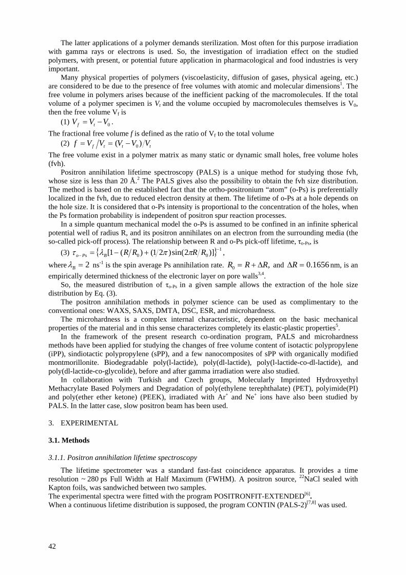
The latter applications of a polymer demands sterilization. Most often for this purpose irradiation with gamma rays or electrons is used. So, the investigation of irradiation effect on the studied polymers, with present, or potential future application in pharmacological and food industries is very important.
Many physical properties of polymers (viscoelasticity, diffusion of gases, physical ageing, etc.) are considered to be due to the presence of free volumes with atomic and molecular dimensions1. The free volume in polymers arises because of the inefficient packing of the macromolecules. If the total volume of a polymer specimen is Vt and the volume occupied by macromolecules themselves is V0, then the free volume Vf is
(1) . 0VVV tf −=The fractional free volume f is defined as the ratio of Vf to the total volume
(2) tttf VVVVVf )( 0−== The free volume exist in a polymer matrix as many static or dynamic small holes, free volume holes (fvh).
Positron annihilation lifetime spectroscopy (PALS) is a unique method for studying those fvh, whose size is less than 20 Å.2 The PALS gives also the possibility to obtain the fvh size distribution. The method is based on the established fact that the ortho-positronium “atom” (o-Ps) is preferentially localized in the fvh, due to reduced electron density at them. The lifetime of o-Ps at a hole depends on the hole size. It is considered that o-Ps intensity is proportional to the concentration of the holes, when the Ps formation probability is independent of positron spur reaction processes.
In a simple quantum mechanical model the o-Ps is assumed to be confined in an infinite spherical potential well of radius R, and its positron annihilates on an electron from the surrounding media (the so-called pick-off process). The relationship between R and o-Ps pick-off lifetime, τo-Ps, is
(3) { } 100 )]2sin()21()(1[ −
− +−= RRRRBPso ππλτ ,
where 2=Bλ ns-1 is the spin average Ps annihilation rate. ,0 RRR Δ+= and nm, is an empirically determined thickness of the electronic layer on pore walls3,4.
1656.0=ΔR
So, the measured distribution of τo-Ps in a given sample allows the extraction of the hole size distribution by Eq. (3).
The positron annihilation methods in polymer science can be used as complimentary to the conventional ones: WAXS, SAXS, DMTA, DSC, ESR, and microhardness.
The microhardness is a complex internal characteristic, dependent on the basic mechanical properties of the material and in this sense characterizes completely its elastic-plastic properties5.
In the framework of the present research co-ordination program, PALS and microhardness methods have been applied for studying the changes of free volume content of isotactic polypropylene (iPP), sindiotactic polypropylene (sPP), and a few nanocomposites of sPP with organically modified montmorillonite. Biodegradable poly(l-lactide), poly(dl-lactide), poly(l-lactide-co-dl-lactide), and poly(dl-lactide-co-glycolide), before and after gamma irradiation were also studied.
In collaboration with Turkish and Czech groups, Molecularly Imprinted Hydroxyethyl Methacrylate Based Polymers and Degradation of poly(ethylene terephthalate) (PET), polyimide(PI) and poly(ether ether ketone) (PEEK), irradiated with Ar+ and Ne+ ions have also been studied by PALS. In the latter case, slow positron beam has been used. 3. EXPERIMENTAL 3.1. Methods 3.1.1. Positron annihilation lifetime spectroscopy
The lifetime spectrometer was a standard fast-fast coincidence apparatus. It provides a time resolution ~ 280 ps Full Width at Half Maximum (FWHM). A positron source, 22NaCl sealed with Kapton foils, was sandwiched between two samples. The experimental spectra were fitted with the program POSITRONFIT-EXTENDED[6]. When a continuous lifetime distribution is supposed, the program CONTIN (PALS-2)[7,8] was used.
42
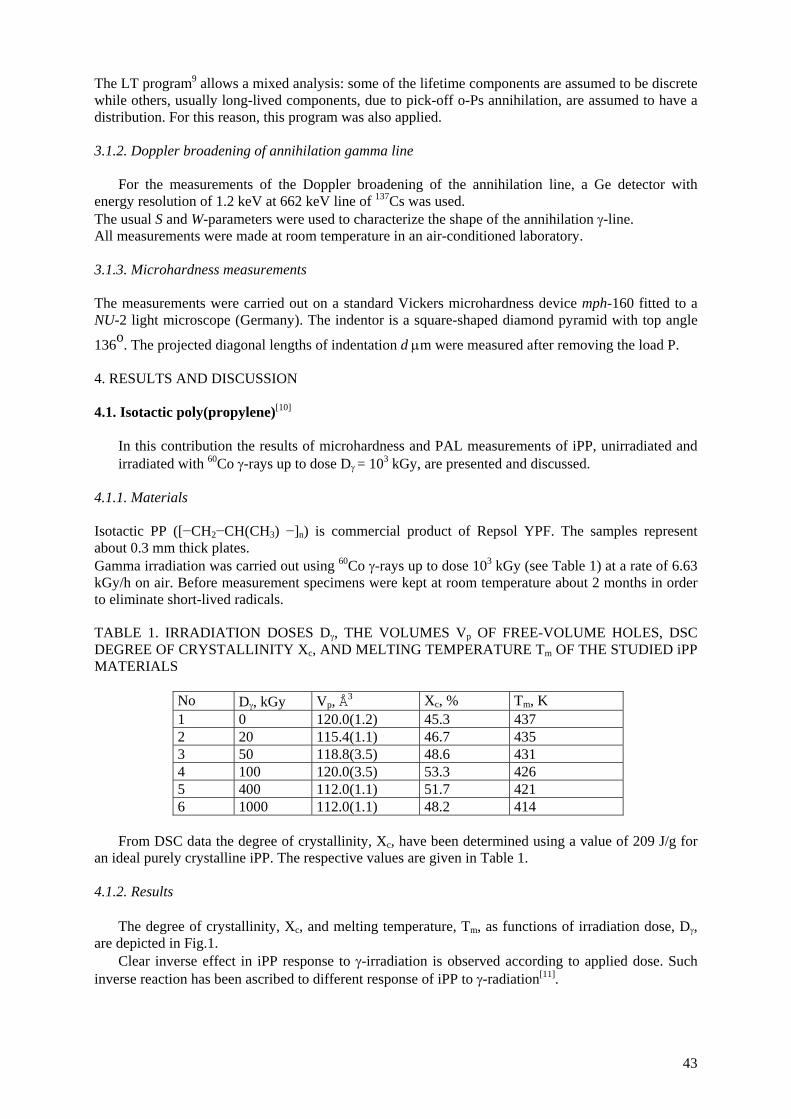
The LT program9 allows a mixed analysis: some of the lifetime components are assumed to be discrete while others, usually long-lived components, due to pick-off o-Ps annihilation, are assumed to have a distribution. For this reason, this program was also applied.
3.1.2. Doppler broadening of annihilation gamma line
For the measurements of the Doppler broadening of the annihilation line, a Ge detector with energy resolution of 1.2 keV at 662 keV line of 137Cs was used. The usual S and W-parameters were used to characterize the shape of the annihilation γ-line. All measurements were made at room temperature in an air-conditioned laboratory.
3.1.3. Microhardness measurements The measurements were carried out on a standard Vickers microhardness device mph-160 fitted to a NU-2 light microscope (Germany). The indentor is a square-shaped diamond pyramid with top angle
136o. The projected diagonal lengths of indentation d μm were measured after removing the load P.
4. RESULTS AND DISCUSSION 4.1. Isotactic poly(propylene)[10]
In this contribution the results of microhardness and PAL measurements of iPP, unirradiated and irradiated with 60Co γ-rays up to dose Dγ = 103 kGy, are presented and discussed.
4.1.1. Materials Isotactic PP ([−CH2−CH(CH3) −]n) is commercial product of Repsol YPF. The samples represent about 0.3 mm thick plates.
Gamma irradiation was carried out using 60Co γ-rays up to dose 103 kGy (see Table 1) at a rate of 6.63 kGy/h on air. Before measurement specimens were kept at room temperature about 2 months in order to eliminate short-lived radicals. TABLE 1. IRRADIATION DOSES Dγ, THE VOLUMES Vp OF FREE-VOLUME HOLES, DSC DEGREE OF CRYSTALLINITY Xc, AND MELTING TEMPERATURE Tm OF THE STUDIED iPP MATERIALS
No Dγ, kGy Vp, Å3 Xc, % Tm, K 1 0 120.0(1.2) 45.3 437 2 20 115.4(1.1) 46.7 435 3 50 118.8(3.5) 48.6 431 4 100 120.0(3.5) 53.3 426 5 400 112.0(1.1) 51.7 421 6 1000 112.0(1.1) 48.2 414
From DSC data the degree of crystallinity, Xc, have been determined using a value of 209 J/g for
an ideal purely crystalline iPP. The respective values are given in Table 1. 4.1.2. Results
The degree of crystallinity, Xc, and melting temperature, Tm, as functions of irradiation dose, Dγ, are depicted in Fig.1.
Clear inverse effect in iPP response to γ-irradiation is observed according to applied dose. Such inverse reaction has been ascribed to different response of iPP to γ-radiation[11].
43
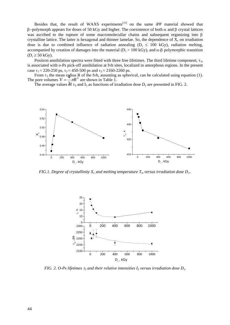
Besides that, the result of WAXS experiments[12] on the same iPP material showed that β−polymorph appears for doses of 50 kGy and higher. The coexistence of both α and β crystal lattices was ascribed to the rupture of some macromolecullar chains and subsequent organizing into β crystalline lattice. The latter is hexagonal and thinner lamelae. So, the dependence of Xc on irradiation dose is due to combined influence of radiation annealing (Dγ ≤ 100 kGy), radiation melting, accompanied by creation of damages into the material (Dγ > 100 kGy), and α-β polymorphic transition (Dγ ≥ 50 kGy).
Positron annihilation spectra were fitted with three free lifetimes. The third lifetime component, τ3, is associated with o-Ps pick-off annihilation at fvh sites, localized in amorphous regions. In the present case τ1 ≈ 220-250 ps, τ2 ≈ 450-500 ps and τ3 ≈ 2160-2260 ps.
From τ3 the mean ra ius R of the fvh, assuming as spherical, can be calculated using equation (1). The pore volumes
d3
3The average values of τ3 and I3 as functions of irradiation dose Dγ are presented in FIG. 2.
4V are shown in Table 1. Rπ=
0 200 400 600 800 10000.44
0.46
0.48
0.50
0.52
0.54
X c
Dγ , kGy
0 200 400 600 800 1000410
420
430
440
T m ,
K
Dγ , kGy
FIG.1. Degree of crystallinity Xc, and melting temperature Tm versus irradiation dose Dγ..
0 200 400 600 800 10002100
2150
2200
2250
2300
τ 3 ,
ps
Dγ , kGy
0 200 400 600 800 10005
10
15
20
25
I 3 , %
FIG. 2. O-Ps lifetimes τ3 and their relative intensities I3 versus irradiation dose Dγ.
44
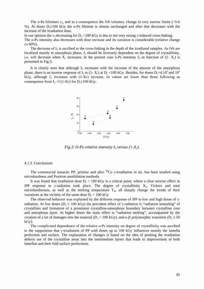
The o-Ps lifetimes τ3, and as a consequence the fvh volumes, change in very narrow limits (~5-6 %). At doses Dγ≤100 kGy the o-Ps lifetime is almost unchanged and after that decreases with the increase of the irradiation dose. In our opinion the τ3 decreasing for Dγ >100 kGy is due to not very strong γ-induced cross-linking. The o-Ps intensity also decreases with dose increase and its variation is considerable (relative change ca 60%).
The decrease of I3 is ascribed to the cross-linking in the depth of the irradiated samples. As fvh are localized mainly in amorphous phase, I3 should be inversely dependent on the degree of crystallinity, i.e. will decrease when Xc increases. In the present case o-Ps intensity I3 as function of (1- Xc) is presented in Fig.3.
It is clearly seen that although I3 increases with the increase of the amount of the amorphous phase, there is an inverse response of I3 to (1- Xc) at Dγ =100 kGy. Besides, for doses Dγ=4.102 and 103
kGy, although I3 increases with (1-Xc) increase, its values are lower than those following as consequence from I3 =f (1-Xc) for Dγ≤100 kGy.
0.46 0.48 0.50 0.52 0.54 0.565
10
15
20
25 1
2
3
4
5
6
I 3 , %
(1-Xc)
Fig.3. O-Ps relative intensity I3 versus (1-Xc).
4.1.3. Conclusions
The commercial isotactic PP, pristine and after 60Co γ-irradiation in air, has been studied using microhardness and Positron annihilation methods.
It was found that irradiation dose Dγ = 100 kGy is a critical point, where a clear inverse effect in iPP response to γ-radiation took place. The degree of crystallinity Xc, Vickers and total microhardnesses, as well as the melting temperature Tm, all sharply change the trends of their variations at the vicinity of the same dose Dγ = 100 kGy
The observed behavior was explained by the different response of iPP to low and high doses of γ-radiation. At low doses (Dγ ≤ 100 kGy) the prevalent effect of γ-radiation is “radiation annealing” of crystallites and formation of a prominent crystalline-amorphous boundary between crystalline core and amorphous layer. At higher doses the main effect is “radiation melting”, accompanied by the creation of a lot of damages into the material (Dγ > 100 kGy), and α-β polymorphic transition (Dγ ≥ 50 kGy).
The complicated dependence of the relative o-Ps intensity on degree of crystallinity was ascribed to the supposition that γ-irradiation of PP with doses up to 100 kGy influences mainly the lamella perfection and surface. The explanation of changes is based on the idea of pushing the irradiation defects out of the crystalline areas into the intermediate layers that leads to improvement of both lamellae and their fold surface perfectness.
45
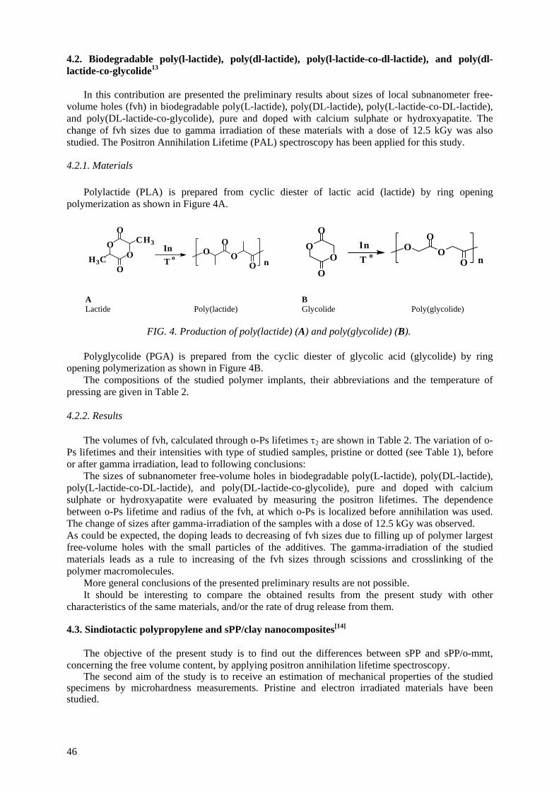
4.2. Biodegradable poly(l-lactide), poly(dl-lactide), poly(l-lactide-co-dl-lactide), and poly(dl-lactide-co-glycolide13
In this contribution are presented the preliminary results about sizes of local subnanometer free-
volume holes (fvh) in biodegradable poly(L-lactide), poly(DL-lactide), poly(L-lactide-co-DL-lactide), and poly(DL-lactide-co-glycolide), pure and doped with calcium sulphate or hydroxyapatite. The change of fvh sizes due to gamma irradiation of these materials with a dose of 12.5 kGy was also studied. The Positron Annihilation Lifetime (PAL) spectroscopy has been applied for this study.
4.2.1. Materials
Polylactide (PLA) is prepared from cyclic diester of lactic acid (lactide) by ring opening polymerization as shown in Figure 4A.
nO O
O
OO
OO
CH3
H3CO
InT o
OO
O
O
oTIn O O
O
O n
A B Lactide Poly(lactide) Glycolide Poly(glycolide)
FIG. 4. Production of poly(lactide) (A) and poly(glycolide) (B).
Polyglycolide (PGA) is prepared from the cyclic diester of glycolic acid (glycolide) by ring opening polymerization as shown in Figure 4B.
The compositions of the studied polymer implants, their abbreviations and the temperature of pressing are given in Table 2.
4.2.2. Results
The volumes of fvh, calculated through o-Ps lifetimes τ2 are shown in Table 2. The variation of o-
Ps lifetimes and their intensities with type of studied samples, pristine or dotted (see Table 1), before or after gamma irradiation, lead to following conclusions:
The sizes of subnanometer free-volume holes in biodegradable poly(L-lactide), poly(DL-lactide), poly(L-lactide-co-DL-lactide), and poly(DL-lactide-co-glycolide), pure and doped with calcium sulphate or hydroxyapatite were evaluated by measuring the positron lifetimes. The dependence between o-Ps lifetime and radius of the fvh, at which o-Ps is localized before annihilation was used. The change of sizes after gamma-irradiation of the samples with a dose of 12.5 kGy was observed. As could be expected, the doping leads to decreasing of fvh sizes due to filling up of polymer largest free-volume holes with the small particles of the additives. The gamma-irradiation of the studied materials leads as a rule to increasing of the fvh sizes through scissions and crosslinking of the polymer macromolecules. More general conclusions of the presented preliminary results are not possible.
It should be interesting to compare the obtained results from the present study with other characteristics of the same materials, and/or the rate of drug release from them.
4.3. Sindiotactic polypropylene and sPP/clay nanocomposites[14]
The objective of the present study is to find out the differences between sPP and sPP/o-mmt, concerning the free volume content, by applying positron annihilation lifetime spectroscopy.
The second aim of the study is to receive an estimation of mechanical properties of the studied specimens by microhardness measurements. Pristine and electron irradiated materials have been studied.
46
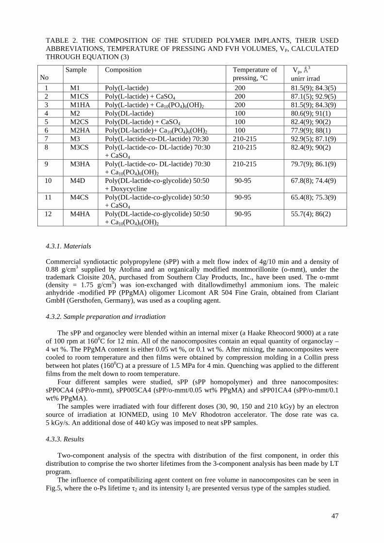
TABLE 2. THE COMPOSITION OF THE STUDIED POLYMER IMPLANTS, THEIR USED ABBREVIATIONS, TEMPERATURE OF PRESSING AND FVH VOLUMES, VP, CALCULATED THROUGH EQUATION (3)
No Sample Composition Temperature of
pressing, °C Vp, Å3 unirr irrad
1 M1 Poly(L-lactide) 200 81.5(9); 84.3(5) 2 M1CS Poly(L-lactide) + CaSO4 200 87.1(5); 92.9(5) 3 M1HA Poly(L-lactide) + Ca10(PO4)6(OH)2 200 81.5(9); 84.3(9) 4 M2 Poly(DL-lactide) 100 80.6(9); 91(1) 5 M2CS Poly(DL-lactide) + CaSO4 100 82.4(9); 90(2) 6 M2HA Poly(DL-lactide)+ Ca10(PO4)6(OH)2 100 77.9(9); 88(1) 7 M3 Poly(L-lactide-co-DL-lactide) 70:30 210-215 92.9(5); 87.1(9) 8 M3CS Poly(L-lactide-co- DL-lactide) 70:30
+ CaSO4 210-215 82.4(9); 90(2)
9 M3HA Poly(L-lactide-co- DL-lactide) 70:30 + Ca10(PO4)6(OH)2
210-215 79.7(9); 86.1(9)
10 M4D Poly(DL-lactide-co-glycolide) 50:50 + Doxycycline
90-95 67.8(8); 74.4(9)
11 M4CS Poly(DL-lactide-co-glycolide) 50:50 + CaSO4
90-95 65.4(8); 75.3(9)
12 M4HA Poly(DL-lactide-co-glycolide) 50:50 + Ca10(PO4)6(OH)2
90-95 55.7(4); 86(2)
4.3.1. Materials Commercial syndiotactic polypropylene (sPP) with a melt flow index of 4g/10 min and a density of 0.88 g/cm3 supplied by Atofina and an organically modified montmorillonite (o-mmt), under the trademark Cloisite 20A, purchased from Southern Clay Products, Inc., have been used. The o-mmt (density = 1.75 g/cm3) was ion-exchanged with ditallowdimethyl ammonium ions. The maleic anhydride -modified PP (PPgMA) oligomer Licomont AR 504 Fine Grain, obtained from Clariant GmbH (Gersthofen, Germany), was used as a coupling agent. 4.3.2. Sample preparation and irradiation
The sPP and organocley were blended within an internal mixer (a Haake Rheocord 9000) at a rate of 100 rpm at 1600C for 12 min. All of the nanocomposites contain an equal quantity of organoclay – 4 wt %. The PPgMA content is either 0.05 wt %, or 0.1 wt %. After mixing, the nanocomposites were cooled to room temperature and then films were obtained by compression molding in a Collin press between hot plates (1600C) at a pressure of 1.5 MPa for 4 min. Quenching was applied to the different films from the melt down to room temperature.
Four different samples were studied, sPP (sPP homopolymer) and three nanocomposites: sPP0CA4 (sPP/o-mmt), sPP005CA4 (sPP/o-mmt/0.05 wt% PPgMA) and sPP01CA4 (sPP/o-mmt/0.1 wt% PPgMA).
The samples were irradiated with four different doses (30, 90, 150 and 210 kGy) by an electron source of irradiation at IONMED, using 10 MeV Rhodotron accelerator. The dose rate was ca. 5 kGy/s. An additional dose of 440 kGy was imposed to neat sPP samples. 4.3.3. Results
Two-component analysis of the spectra with distribution of the first component, in order this distribution to comprise the two shorter lifetimes from the 3-component analysis has been made by LT program.
The influence of compatibilizing agent content on free volume in nanocomposites can be seen in Fig.5, where the o-Ps lifetime τ2 and its intensity I2 are presented versus type of the samples studied.
47

1 2 3 4
2280
2290
2300
2310
2320
PPgMA, wt%0.10.0500
τ 2 ,
ps
sample
1 2 3 4
27.2
27.6
28.0
I 2 , %
FIG. 5. O-Ps lifetime τ2 and its intensity I2 versus type of the studied samples.
The values of free-volume hole radii R, calculated by eq. (1) are in a narrow range of 3.10(1) Å to
3.30(1) Å. The corresponding fvh sizes vary between (124.7±1.2) Å3 and (137.2±1.3) Å[3]. As it is seen from fig.5, adding of 4 wt% o-mmt to neat sPP leads to a small decrease of τo-Ps , i.e. of free-volume hole size.
Results of WAXS measurements on the same samples[15] showed that sPP macromolecules have been at least intercalated between the sheets of the clay. In the absence of the compatibilizing agent, there is no good compatibility between sPP and the clay particles. This loose connection between o-mmt and polymer matrix hinder in some extend the macromolecular mobility, and this might be the cause for the slight diminution of τo-Ps.
The addition of PPgMA to PP/o-mmt composite, due to its weak plasticizing effect leads to a slight increase of τo-Ps.
The o-Ps intensity (Fig.5) slightly increases (1.9 %) from the #1 to #3 samples, and after that, decreases (2.2 %) for sample #4.
The influence of electron irradiation on the free volume in nanocomposites can be seen in Fig.6 and Fig.7. There the o-Ps lifetimes and their intensities are presented versus irradiation dose.
According to Cerrada et al.[15], the electron irradiation of the present samples has a significant effect on sPP/o-mmt composites, namely the intercalation level has considerably increased.
Our results however (Figs.6 and 7) show that neither improved compatibility nor higher intercalation level (which is a consequence of the former), have any influence on the o-Ps lifetime and intensity as there is no difference between neat sPP and sPP/o-mmt.
In figures 8, a) and b), MHV and MHT for the studied different kinds of unirradiated samples are presented.
The addition of PPgMA to sPP/o-mmt (sample #3) favors the better dispersion of the clay particles, and gives rise of adhesion between the sPP matrix and o-mmt platelets surface. This promotes the transferring of the stress under the indentor from the polymer matrix to the reinforcing o-mmt particles, and MHV increases. The additional amount of PPgMA does not further improve MHV (sample #4). So, sample #3 is harder than the neat sPP polymer. Simultaneously, MHT decreases as compared to #2, i.e., the material become more elastic.
The results of microhardness measurements of samples #2 and #3, after their electron irradiation with a dose of 30 kGy, are depicted in Fig.8, also.
As a whole, microhardness measurements reveal that introducing of 0.05 wt % of PPgMA coupling agent to sPP/o-mmt nanocomposite, augments MHV with ca. 8 %. The electron irradiation of PP/o-mmt (not containing coupling agent), arouses an increase of MHV slightly over those of sPP homopolymer. The irradiation decreases drastically MHV for PP/o-mmt/0.05 wt-PPgMA nanocomposite.
48

0 50 100 150 200 2502280
2300
2320
2340
2360
2380
2400
2420
sPP sPP0CA4 sPP005CA4 sPP01CA4
τ 2 ,
ps
D, kGy FIG. 6. O-Ps lifetimes of neat sPP and sPP/o-mmt composites versus irradiation dose.
0 50 100 150 200 250
18
20
22
24
26
28
sPP sPP0CA4 sPP005CA4 sPP01CA4
I 2 , %
D, kGy
FIG. 7. O-Ps intensities of neat sPP and sPP/o-mmt composites versus irradiation dose.
1 2 3 4
41
42
43
44
45
46
47
a
MH
V, M
Pa
Sample
nonirradiated irradiated
1 2 3 4
2
4
6
8
10
12
14
b
MH
T, M
Pa
Sample
nonirradiated irradiated
FIG. 8. MHV and MHT for the different kinds of studied samples.
49
4.3.4. Conclusions
The PALS applied to the sPP homopolymer and three nanocomposites, containing 4 wt% of layered silicate and 0, 0.05, 0.1 wt% of maleic anhydride- modified PP, as coupling agent, revealed that at the present experimental conditions, there is a scarcely perceptible difference between them. The free-volume hole sizes in the studied specimens are the same (125±1) Å[3] within the error limit.
The variation of o-Ps intensity implies that there is small increase in the free volume, due to the clay and coupling agent incorporation into the polymer matrix.
The electron irradiation of sPP and its nanocomposites leads to a noticeable increase of the o-Ps lifetime. The free-volume size reaches to (137±1) Å[3] for the pure sPP at a dose of 150 kGy. The intensity of o-Ps decreases from ca. 27.5 % to about 19 %, mainly due to the presence of carbonyl groups, created during irradiation.
The microhardness of the studied materials also varies in not very wide range. The introducing of 0.05 wt % of PPgMA coupling agent to sPP/o-mmt nanocomposite leads to an increase of the MHV with ca. 8 % with respect to the neat sPP polymer. The electron irradiation decreases drastically MHV for PP/o-mmt/0.05 wt-PPgMA nanocomposite.
From our results it follows that the present experimental conditions lead to manufacture of sPP nanocomposites with moderately improved mechanical properties in comparison with sPP homopolymer. 4.4. Molecularly Imprinted Hydroxyethyl Methacrylate Based Polymers[16]
The major goal of this study is to determine and control the sizes of the free-volume holes produced during the synthesis of glucose imprinted Hydroxyethyl methacrylate based polymers by means of PAL spectroscopy.
Obtained results suggests that control of free volume based on template molecule by changing parameters of imprinting system is feasible in nano scale by means of positron annihilation lifetime (PAL) spectroscopy technique.
4.4.1. Materials
The crosslinking agents; diethylene glycol diacrylate (DEGDA) and polypropylene glycol dimethacrylate (PPGDMA with Mn= 560) were purchased from Aldrich (Milwaukee, USA), triethylene glycol dimethacrylate (TEGDMA) was purchased from Aldrich (Steinheim, Germany). The template molecule, D-glucose and functional monomer, 2- hydroxyethyl methacrylate (HEMA) were obtained from Fluka (Buchs, Switzerland). The solvents; dimethyl sulfoxide (DMSO) and ethanol (EtOH) were purchased from Merck (Darmstadt, Germany). All chemicals were analytical grade and used as received.
4.4.2. Results
PALS and Doppler broadening of annihilation 511 keV gamma line were used to study the effect of type and amount of the crosslinking agent, of template concentration, and of radiation dose in dry and swollen samples.
Fig. 9 shows the effect of type and amount of the crosslinking agent. The values for the radii are calculated by iteration procedure based on Eq.3. Fig. 10 shows the PALS results for the same MIP samples used in Fig.9, this time fully swollen in water. Irrespective of chain length of crosslinking agent and its concentration, the free-volume hole radius determined for these MIPs were found to be the same for all systems.
What is measured by PAL spectroscopy in this case is the free volume not occupied by water. At higher water concentration, the o-Ps lifetime reaches a saturation value that corresponds to free volume hole radius of 0.28 nm. The last value is the Ps-bubble size in water at room temperature which means that Ps is formed in bulk water fully or partially occupying the free volume hole [17].
50

a) b)
FIG. 9. Free-volume hole radius (a) and o-Ps intensity (b) for dry samples versus the type of the crosslinking agent at different concentrations. 5 kGy irradiated samples with 3:1 HEMA: Glucose mol ratio; symbols ▲, □, ◊, , ■ indicate 70, 30, 20, 10% and no crosslinking agent containing samples, respectively. NA indicates sample prepared without crosslinking agent.
a) b)
FIG. 10. Free-volume hole radius (a) and o-Ps intensity (b) for water swollen samples versus the type of the crosslinking agent at different concentrations. 5 kGy irradiated samples with 3:1 HEMA: Glucose mol ratio; symbols ▲, □, ◊, , ■ indicate 70, 30, 20, 10% and no crosslinking agent containing samples, respectively. NA indicates sample prepared without crosslinking agent.
a) b)
FIG. 11. Free-volume hole radius, R ,(a) and o-Ps intensity (b) versus HEMA/Glucose (H:G) ratio. NA indicates samples prepared without crosslinking agent. 5 kGy irradiated samples with 3:1 and 6:1 HEMA: Glucose mol ratio; symbols ●, ○, ■, □ indicates NA in dry state, NA in swollen state, %30 TEGDMA in dry state , %30 TEGDMA in swollen state, respectively.
51
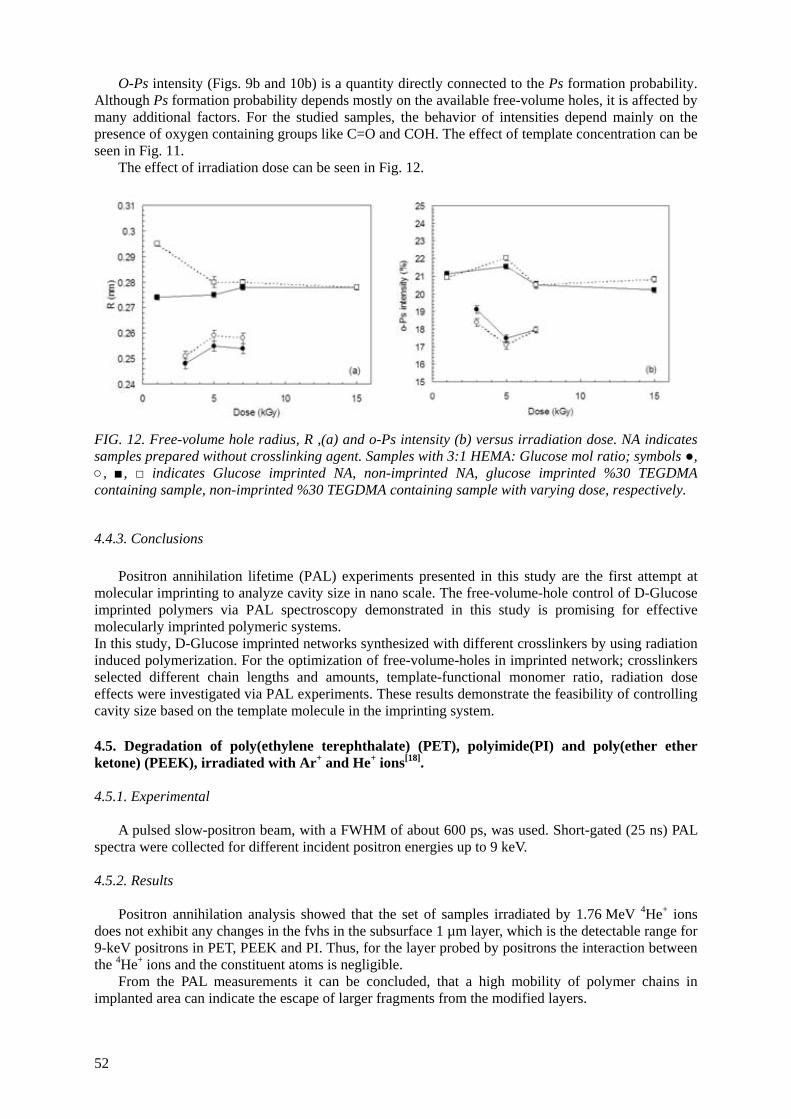
O-Ps intensity (Figs. 9b and 10b) is a quantity directly connected to the Ps formation probability. Although Ps formation probability depends mostly on the available free-volume holes, it is affected by many additional factors. For the studied samples, the behavior of intensities depend mainly on the presence of oxygen containing groups like C=O and COH. The effect of template concentration can be seen in Fig. 11.
The effect of irradiation dose can be seen in Fig. 12.
FIG. 12. Free-volume hole radius, R ,(a) and o-Ps intensity (b) versus irradiation dose. NA indicates samples prepared without crosslinking agent. Samples with 3:1 HEMA: Glucose mol ratio; symbols ●, ○, ■, □ indicates Glucose imprinted NA, non-imprinted NA, glucose imprinted %30 TEGDMA containing sample, non-imprinted %30 TEGDMA containing sample with varying dose, respectively.
4.4.3. Conclusions Positron annihilation lifetime (PAL) experiments presented in this study are the first attempt at
molecular imprinting to analyze cavity size in nano scale. The free-volume-hole control of D-Glucose imprinted polymers via PAL spectroscopy demonstrated in this study is promising for effective molecularly imprinted polymeric systems. In this study, D-Glucose imprinted networks synthesized with different crosslinkers by using radiation induced polymerization. For the optimization of free-volume-holes in imprinted network; crosslinkers selected different chain lengths and amounts, template-functional monomer ratio, radiation dose effects were investigated via PAL experiments. These results demonstrate the feasibility of controlling cavity size based on the template molecule in the imprinting system. 4.5. Degradation of poly(ethylene terephthalate) (PET), polyimide(PI) and poly(ether ether ketone) (PEEK), irradiated with Ar+ and He+ ions[18]. 4.5.1. Experimental
A pulsed slow-positron beam, with a FWHM of about 600 ps, was used. Short-gated (25 ns) PAL spectra were collected for different incident positron energies up to 9 keV.
4.5.2. Results
Positron annihilation analysis showed that the set of samples irradiated by 1.76 MeV 4He+ ions
does not exhibit any changes in the fvhs in the subsurface 1 µm layer, which is the detectable range for 9-keV positrons in PET, PEEK and PI. Thus, for the layer probed by positrons the interaction between the 4He+ ions and the constituent atoms is negligible.
From the PAL measurements it can be concluded, that a high mobility of polymer chains in implanted area can indicate the escape of larger fragments from the modified layers.
52
5. GENERAL CONCLUSIONS
The information, obtained by PA methods is additional to that, obtained through such conventional methods as WAXS, SAXS, DMTA, DSC, ESR, and microhardness.
Combination of PA methods with conventional ones permits to obtain more deep insight into the microstructure of polymers.
It is worth to note that the process of positron annihilation in polymers is very complicated. On the other hand, the polymers themselves exhibit complex structures difficult to be understood theoretically. Because of these two circumstances, the application of PA methods to polymer studies has two major goals:
• to understand the behaviour of positrons into polymer materials well characterised with other (conventional) methods;
• to understand the microstructure and its evolution under different treatments of polymers, taking advantage of known properties of positron annihilation.
ACKNOWLEDGEMENTS
This work is partially supported by International Atomic Energy Agency under Research Agreement No 12701. We would like to thank Prof. I.Rashkov and Dr. M.Spassova for supplying the biodegradable lactides and useful discussion.
All of the authors highly appreciate support of the IAEA through CRP ” Controlling of degradation effects in radiation processing of polymers” for the establishment of collaboration between respective laboratories.
REFERENCES
[1] JEAN, Y.C., “Positron annihilation in polymers”, Mater.Sci.Forum 175-178(1995) 59-70. [2] DLUBEK, G., KILBURN, D., BONDARENKO, V., PIONTECK, J., KRAUSE-REHBERG, R.,
ASHRAF ALAM, M.,”Positron annihilation: a unique method for studying polymers”, Macromol.Symp. 210 (2004) 11-20.
[3] NAKANISHI, H., WANG, S.J., AND JEAN, Y.C., “Macroscopic surface tension studied by positron annihilation”, In: Positron Annihilation Studies of Fluids, Ed. by S.C.Sharma, World Scientific, Singapore, (1988) 292-298
[4] ELDRUP, M., LIGHTBODY, D., AND SHERWOOD,J.N., “The temperature dependence of positron lifetimes in solid pivalic acid”, Chem.Phys. 63 (1981) 51-58.
[5] BALTA CALLEJA, F.J., “Principles of polymer structure and morphology”, NATO/ASI, Portugal, May, 99
[6] KIRKEGAARD, P., ELDRUP, M., MOGENSEN, O.E. AND PEDERSEN, N.J., “Program system for analyzing positron lifetime spectra and angular correlation curves”, Comput.Phys.Commun. 23 (1981) 307-335
[7] GREGORY, R., “Free-volume and pore size distributions determined by numerical Laplace inversion of positron annihilation lifetime data”, J.Appl.Phys. 70 (1991) 4665-4670
[8] GREGORY, R., ZHU, Y., “Analysis of PAL data by numerical Laplace inversion with the program CONTIN”, Nucl. Instr. And Meth. A 290 (1990) 172-182
[9] KANSY, J., “Microcomputer program for analysis of positron annihilation lifetime spectra”, Nucl.Instr.Meth. A374(2) (1996) 235-244.
[10] MISHEVA, M., ZAMFIROVA , G., GAYDAROV , V., PEREÑA, J.M., CERRADA, M.L., PÉREZ, E.,BENAVENTE, R., “Gamma irradiation effect on isotactic poly(propylene) studied by microhardness and positron annihilation lifetime methods”, to be submitted
[11] VALENZA, A., PICCAROLO, S., SPADARO, G., “Influence of morphology and chemical structure on the inverse response of PP to gamma radiation under vacuum”, Polymer 40 (1999) 835-841.
53
[12] SERRADA, M.L., PEREZ, E., ALVAREZ, C., BELLO, A., BENAVENTE, R., PERENA, J.M., “Polymorphisme in conventional isitactic polypropylene by effect of gamma radiation” in:Controlling of degradation effects in radiation processing of polymers, internal report of the 1st RCM of the CRPF2.20.39 held in Vienna, 8-11 December 2003, p.137 zag.
[13] MISHEVA, M., DJOURELOV, N., “Positron annihilation lifetime study of biodegradable poly(l-lactide), poly(dl-lactide), poly(l-lactide-co-dl-lactide), and poly(dl-lactide-co-glycolide), before and after gamma irradiation”, 2nd RCM report of the CRP F2.20.39, held in Madrid, Spain from 11 to 15 July 2005.
[14] MISHEVA, M., DJOURELOV, N., ZAMFIROVA, G., GAYDAROV, V., CERRADA, M.L., RODRÍGUEZ-AMOR, V., PÉREZ, E., “ Effect of compatibilizer and electron irradiation on free-volume and microhardness of syndiotactic polypropilene/clay nanocomposites”, to be submitted
[15] CERRADA, M.L., RODRIGUEZ-AMOR, V., PÉREZ, E. “Effect of clay nanoparticles and electron irradiation in the crystallization rate of syndiotactic Polypropylene”. J. Polym Sci. Polym. Phys. Submitted.
[16] DJOURELOV, N., ATEŞ, Z., GÜVEN, O., MISHEVA, M., SUZUKI, T., “Positron Annihilation Lifetime Spectroscopy of Molecularly Imprinted Hydroxyethyl Methacrylate Based Polymers”, sent to Polymer
[17] Ito, K., Ujihira, Y., Yamadshita, T., Horie, K., “Positron annihilation study of continous volume phase transition of poly(N-isopropylacrylamide) gel induced in methanol-water mixed solvent”, J.Pol.Sci.:Part B: Polymer Physics, 36 (1998), 1141-1151.
[18] Mackova, A., Havranek, V., Svorcik, V., Djourelov, N., Suzuki, T., “Degradation of PET, PEEK and PI induced by irradiation with 150 keV Ar+ and 1.76 MeV He+ ions”, Nucl.Instr.Meth. Phys.Res. B 240 (2005) 245-249.
54
ANALYSIS OF PLASMA TREATED METALLIZED POLYMERS AND CONVENTIONAL POLYMERS MODIFIED BY VARIOUS TECHNIQUES
A. MACKOVÁ1 Nuclear Physics Institute, AS CR Rez, Czech Republic
Collaborating Laboratories and Co-authors V. ŠVORČÍK2, P. SAJDL3, Z. STRÝHAL4, J. PAVLÍK4, P. MALINSKÝ4, M. ŠLOUF5, M. MISHEVA6, N. DJOURELOV7 1Nuclear Physics Institute, Academy of Sciences of the Czech Republic, Řež u Prahy, Czech Republic 2Department of Solid State Engineering, Institute of Chemical Technology, Prague, Czech Republic 3Department of Power Engineering, Institute of Chemical Technology, Prague, Czech Republic 4Department of Physics, Faculty of Science, J. E. Purkinje University, Ústí nad Labem, Czech Republic 5Institute of Macromolecular Chemistry, Academy of Sciences of the Czech Republic, Prague, Czech Republic 6Faculty of Physics, Sofia University, Sofia, Bulgaria 7Institute for Nuclear Research and Nuclear Energy, Bulgarian Academy of Sciences, Sofia, Bulgaria.
Abstract
This paper summarizes the research activities during the period of 2005-2006. The research is performed at Nuclear Physics Institute of Academy of Sciences of the Czech Republic. There are topics presented: diffusion of metals in polymer foils and metal cluster formation under plasma treatment investigated using analytical methods RBS, AFM, XPS and TEM. Rutherford Backscattering Spectroscopy (RBS) and Elastic Recoil Detection Analysis (ERDA) were employed to determine the composition and elements depth distribution of studied samples. Atomic Force Microscopy (AFM) was used to investigate morphology of metal surface after plasma exposure. X ray Photoelectron Spectroscopy (XPS) gives information on metal-polymer interaction and chemical state of metal atoms. Transmission Electron Microscopy (TEM) analyzed the metal/polymer interface and visualized metal cluster formation. The short summary of all-important topics studied in the frame of the project in 2003-2006 is placed at the end.
1. INTRODUCTION
1.1. Metallized Polymers Metallic films are of a great importance in manufacturing advanced electronic, optical and
mechanical devices ranging from displays to biosensors [1]. For example in microelectronics this metallized films form basic structures for construction of diodes with negative differential resistance and light-emitting [2], polymer based diodes in optoelectronics. The mechanical and electric properties of the metal-polymer interface are influenced by the degree of metal mobility in polymer [3]. Less reactive metals diffuse deep into the polymer at elevated temperatures, but the aggregation tendency inhibits the atomic diffusion and gives place to a complicated cluster diffusion mechanism [4]. Gold is a superior candidate for the metallization of electronic or photonic devices, due to its excellent resistance to electromigration, high electrical and thermal conductivity and excellent plating property [5]. Ag exhibits higher mobility in polymers in comparison with more reactive metals such as Cr or Ti [5]. The complex processes induced by plasma treatment and annealing, which take place on metal/polymer interface (metal atom diffusion, metal cluster formation and their mobility at metal/polymer interface), are far from being understood. In this study, the effect of plasma treatment and annealing on the diffusion of Ag and Au in polyethyleneterephthalate is examined.
55

1.2. Plasma Treated Polymers For various applications of polyethylene (PE) it is desirable to modify its surface properties.
The irradiation (e.g. with laser light, ion and electron beams, UV light, X and γ rays) or treatment in plasma discharge leads to degradation of polymeric chains, chemical bond cleavage, creation of free radicals and release of gaseous degradation products. Subsequent chemical reactions of transient, highly reactive species result in creation of excessive double bonds, production of low mass stable degradation products, large crosslinked structures and eventually oxidized structures [6,7]. The irradiation of non-polar polyolefins (PE, PP, PS and fluoropolymers) leads to creation of polar groups on the polymer surface and in this way it enhances printability, wettability, adhesion with inorganic materials (e.g. metals) or with biologically active components [8]. One of the possible modification techniques, mentioned above, is the polymer exposure to plasma discharge. The degree of modification and character of induced changes depend on the composition of ambient atmosphere, energy of plasma ions, temperature during the treatment and discharge power.
The modification mostly proceeds due to interaction of radicals and ions with polymer surface [9]. By varying the above factors it is possible to change continuously the chemical and physical properties of modified polymer surface, such as wettability, adhesion, chemical resistance, lubrication or biocompatibility [10,11]. The plasma treatment is advantageous in several respects: • only thin surface layer (tens of micrometer thick) of polymer is modified and the polymer bulk
saves its good mechanical properties, • resulting properties of the modified surface layer can be affected by composition of ambient
atmosphere, • high lateral homogeneity of modified polymer surface can be achieved. Clear disadvantage of the plasma treatment is extremely complex process of plasma etching complicating correct adjustment of plasma discharge parameters such as composition, flow and pressure of the gas, substrate temperature, reactor geometry, discharge power and frequency. 2. EXPERIMENTAL
2.1. RBS, AFM, XPS and TEM Study of Metal and Polymer Interface Modified by Plasma Treatment
Metal layers were deposited onto 50μm thick polyethyleneterephthalate (PET, Tm= 2600C, Tg ≈ 980C) supplied by Goodfellow Ltd. The Au and Ag were deposited by diode sputtering on a BAL-TEC, SCD 050 device. The typical deposition parameters were: room deposition temperature, deposition time 65 s, total argon pressure about 4 Pa, electrode distance of 50 mm and current of 20 mA [12].
Plasma treatment and annealing were performed simultaneously in the chamber for plasma surface modification of thin film [13]. The RF discharge (13.56 MHz) was applied in pure argon or an oxygen/argon mixture (47 % O2 and 53% Ar). The flow rates were adjusted in order to obtain a total mixture pressure of 50 – 100 Pa, which was found to be the optimum pressure for plasma ignition at an RF power of 35 W. The sample was held on the plasma floating potential during the plasma treatment. The in situ mounted quartz lamp (20 W) in a polished stainless steel reflector was used for indirect heating of the sample holder to temperatures from 80 °C to 160 °C. Concentration depth profiles of the metal atoms from the RBS spectra were obtained. The beam of 2.68 MeV He+ ions from Van de Graaf accelerator was used for RBS analysis measured at 170° laboratory scattering angle and using incoming angle 75°.
An Omicron Nanotechnology ESCAProbeP spectrometer was used to measure the X ray photoelectron spectra (XPS). The X ray source was monochromated at 1486.7 eV. The exposed and analyzed area had dimensions of 2x3 mm2. The spectra were measured stepwise with a step in binding energy of 0.05 eV. Frequently measured width of line on of C 1s on PE as model polymer is typically 0,9 eV.
Specimens for transmission electron microscopy (TEM) were cut from the centre of the PET foils with embedded metal nanoparticles and fixed in epoxy resin (Durcupan). Ultrathin cross-sections (ca
56
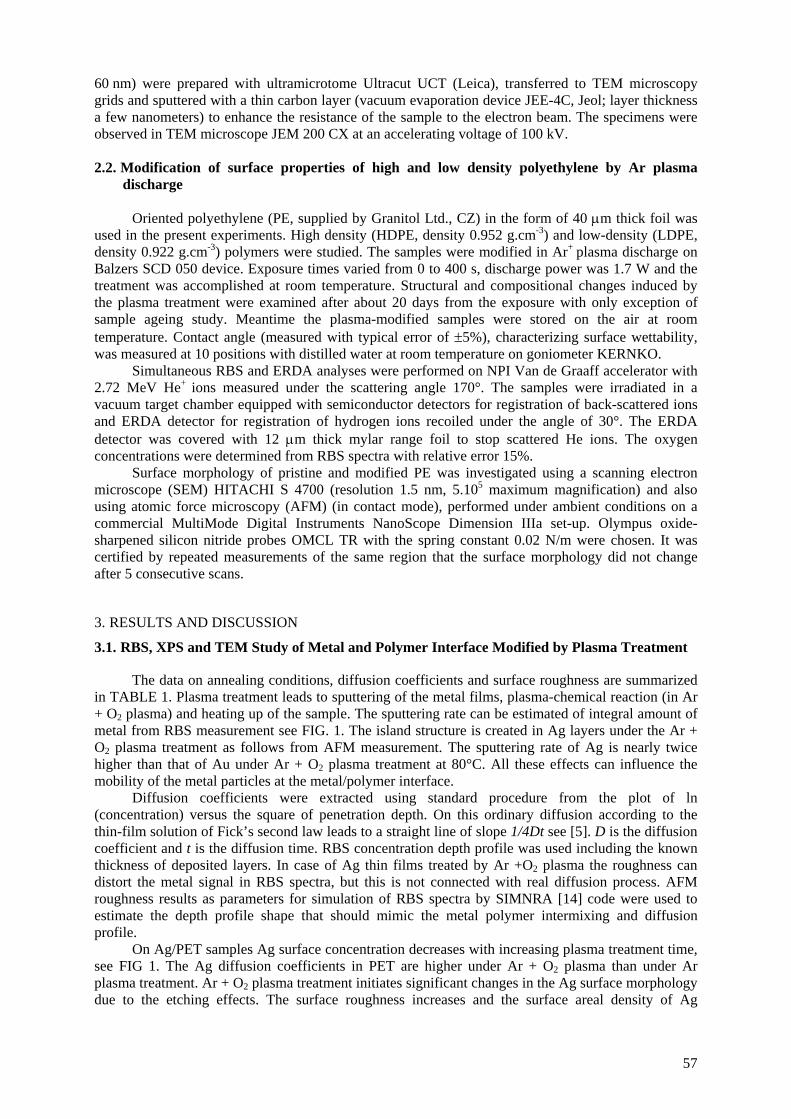
60 nm) were prepared with ultramicrotome Ultracut UCT (Leica), transferred to TEM microscopy grids and sputtered with a thin carbon layer (vacuum evaporation device JEE-4C, Jeol; layer thickness a few nanometers) to enhance the resistance of the sample to the electron beam. The specimens were observed in TEM microscope JEM 200 CX at an accelerating voltage of 100 kV. 2.2. Modification of surface properties of high and low density polyethylene by Ar plasma
discharge
Oriented polyethylene (PE, supplied by Granitol Ltd., CZ) in the form of 40 μm thick foil was used in the present experiments. High density (HDPE, density 0.952 g.cm-3) and low-density (LDPE, density 0.922 g.cm-3) polymers were studied. The samples were modified in Ar+ plasma discharge on Balzers SCD 050 device. Exposure times varied from 0 to 400 s, discharge power was 1.7 W and the treatment was accomplished at room temperature. Structural and compositional changes induced by the plasma treatment were examined after about 20 days from the exposure with only exception of sample ageing study. Meantime the plasma-modified samples were stored on the air at room temperature. Contact angle (measured with typical error of ±5%), characterizing surface wettability, was measured at 10 positions with distilled water at room temperature on goniometer KERNKO.
Simultaneous RBS and ERDA analyses were performed on NPI Van de Graaff accelerator with 2.72 MeV He+ ions measured under the scattering angle 170°. The samples were irradiated in a vacuum target chamber equipped with semiconductor detectors for registration of back-scattered ions and ERDA detector for registration of hydrogen ions recoiled under the angle of 30°. The ERDA detector was covered with 12 μm thick mylar range foil to stop scattered He ions. The oxygen concentrations were determined from RBS spectra with relative error 15%.
Surface morphology of pristine and modified PE was investigated using a scanning electron microscope (SEM) HITACHI S 4700 (resolution 1.5 nm, 5.105 maximum magnification) and also using atomic force microscopy (AFM) (in contact mode), performed under ambient conditions on a commercial MultiMode Digital Instruments NanoScope Dimension IIIa set-up. Olympus oxide-sharpened silicon nitride probes OMCL TR with the spring constant 0.02 N/m were chosen. It was certified by repeated measurements of the same region that the surface morphology did not change after 5 consecutive scans.
3. RESULTS AND DISCUSSION
3.1. RBS, XPS and TEM Study of Metal and Polymer Interface Modified by Plasma Treatment
The data on annealing conditions, diffusion coefficients and surface roughness are summarized in TABLE 1. Plasma treatment leads to sputtering of the metal films, plasma-chemical reaction (in Ar + O2 plasma) and heating up of the sample. The sputtering rate can be estimated of integral amount of metal from RBS measurement see FIG. 1. The island structure is created in Ag layers under the Ar + O2 plasma treatment as follows from AFM measurement. The sputtering rate of Ag is nearly twice higher than that of Au under Ar + O2 plasma treatment at 80°C. All these effects can influence the mobility of the metal particles at the metal/polymer interface.
Diffusion coefficients were extracted using standard procedure from the plot of ln (concentration) versus the square of penetration depth. On this ordinary diffusion according to the thin-film solution of Fick’s second law leads to a straight line of slope 1/4Dt see [5]. D is the diffusion coefficient and t is the diffusion time. RBS concentration depth profile was used including the known thickness of deposited layers. In case of Ag thin films treated by Ar +O2 plasma the roughness can distort the metal signal in RBS spectra, but this is not connected with real diffusion process. AFM roughness results as parameters for simulation of RBS spectra by SIMNRA [14] code were used to estimate the depth profile shape that should mimic the metal polymer intermixing and diffusion profile.
On Ag/PET samples Ag surface concentration decreases with increasing plasma treatment time, see FIG 1. The Ag diffusion coefficients in PET are higher under Ar + O2 plasma than under Ar plasma treatment. Ar + O2 plasma treatment initiates significant changes in the Ag surface morphology due to the etching effects. The surface roughness increases and the surface areal density of Ag
57
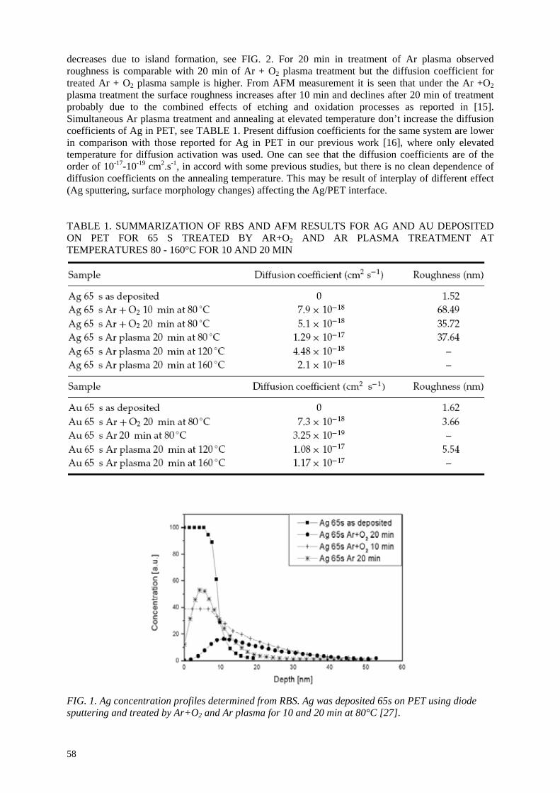
decreases due to island formation, see FIG. 2. For 20 min in treatment of Ar plasma observed roughness is comparable with 20 min of Ar + O2 plasma treatment but the diffusion coefficient for treated Ar + O2 plasma sample is higher. From AFM measurement it is seen that under the Ar +O2 plasma treatment the surface roughness increases after 10 min and declines after 20 min of treatment probably due to the combined effects of etching and oxidation processes as reported in [15]. Simultaneous Ar plasma treatment and annealing at elevated temperature don’t increase the diffusion coefficients of Ag in PET, see TABLE 1. Present diffusion coefficients for the same system are lower in comparison with those reported for Ag in PET in our previous work [16], where only elevated temperature for diffusion activation was used. One can see that the diffusion coefficients are of the order of 10-17-10-19 cm2.s-1, in accord with some previous studies, but there is no clean dependence of diffusion coefficients on the annealing temperature. This may be result of interplay of different effect (Ag sputtering, surface morphology changes) affecting the Ag/PET interface.
TABLE 1. SUMMARIZATION OF RBS AND AFM RESULTS FOR AG AND AU DEPOSITED ON PET FOR 65 S TREATED BY AR+O2 AND AR PLASMA TREATMENT AT TEMPERATURES 80 - 160°C FOR 10 AND 20 MIN
FIG. 1. Ag concentration profiles determined from RBS. Ag was deposited 65s on PET using diode sputtering and treated by Ar+O2 and Ar plasma for 10 and 20 min at 80°C [27].
58
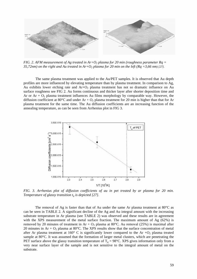
FIG. 2. AFM measurement of Ag treated in Ar+O2 plasma for 20 min (roughness parameter Rq = 35,72nm) on the right and Au treated in Ar+O2 plasma for 20 min on the left (Rq =3,66 nm) [27].
The same plasma treatment was applied to the Au/PET samples. It is observed that Au depth profiles are more influenced by elevating temperature than by plasma treatment. In comparison to Ag, Au exhibits lower etching rate and Ar+O2 plasma treatment has not so dramatic influence on Au surface roughness see FIG 2. Au forms continuous and thicker layer after shorter deposition time and Ar or Ar + O2 plasma treatment influences Au films morphology by comparable way. However, the diffusion coefficient at 80°C and under Ar + O2 plasma treatment for 20 min is higher than that for Ar plasma treatment for the same time. The Au diffusion coefficients are an increasing function of the annealing temperature, as can be seen from Arrhenius plot in FIG 3.
FIG. 3. Arrhenius plot of diffusion coefficients of au in pet treated by ar plasma for 20 min. Temperature of glassy transition tg is depicted [27].
The removal of Ag is faster than that of Au under the same Ar plasma treatment at 80°C as can be seen in TABLE 2. A significant decline of the Ag and Au integral amount with the increasing substrate temperature in Ar plasma (see TABLE 2) was observed and these results are in agreement with the XPS measurement of the metal surface fraction. The maximum amount of Ag (62%) is removed by 20 minutes of treatment in Ar + O2 plasma at 80°C. Au removal (25%) is maximal after 20 minutes in Ar + O2 plasma at 80°C. The XPS results show that the surface concentration of metal after Ar plasma treatment at 160° C is significantly lower compared to the Ar +O2 plasma treated sample at 80°C. It was assumed that the formation of larger metal clusters, which are penetrating the PET surface above the glassy transition temperature of Tg = 98°C. XPS gives information only from a very near surface layer of the sample and is not sensitive to the integral amount of metal on the substrate.
59
TABLE 2. SUMMARY OF THE PLASMA TREATMENT CONDITIONS AND INTEGRAL AMOUNT OF METAL DETERMINED USING RBS. SURFACE CONCENTRATION OF DEPOSITED METALS DETERMINED USING XPS
Sample with deposited Ag
Integral metal amount from RBS [1015 atoms/cm2]
Surface fraction of metal from XPS [atomic %]
as deposited 38.0 23.7 Ar+O2 plasma, 10 min., 80°C 30.3 ---- Ar+O2 plasma, 20 min., 80°C 14.5 11.2
Ar plasma, 20 min., 80°C 37.8 20.2 Ar plasma, 20 min., 120°C 33.9 3.6 Ar plasma, 20 min., 160°C 21.0 3.5
Sample with deposited Au
as deposited 49.6 43.9 Ar+O2 plasma, 20 min., 80°C 37.2 33.2
Ar plasma, 20 min., 80°C 47.2 45.7 Ar plasma, 20 min., 120°C 48.0 29.7 Ar plasma, 20 min., 160°C 39.7 17.3
XPS measurement reflects the dramatic changes in the Ag/PET surface composition. It is
possible to separate the signals in the XPS spectra and determine the chemical state of Ag (see FIG 4a). XPS measurement of Ag (core level 3d5/2) includes Ag+ in Ag2O (367.2 eV), Ag0 (368.3 eV). After plasma treatment (FIG. 4b) the line can be separated into at least three components. The third component (maximum at 369.0 eV) can be interpreted like Ag bonded on the organic structure (Ag-C) [17] or result of differential charging caused by Ag clusters and possible degradation of PET surface [18,19]. Verification of these both processes (charging and degradation) on plasma modified PET/Ag supports results of the C1s and O1s XPS spectra showed in FIG. 4b. The prevailing chemical state is Ag –C bonded on the reactive places (e.g. radicals) of the plasma modified polymer chain.
The creation of intermixed metal-polymer interface was also confirmed by TEM observation, but the number of intermixed metal particles is very low. TEM micrographs are presented in FIG. 5. Ag particles are clearly seen near the polymer metal interface. The increasing substrate temperature used during Ar plasma treatment causes the decline of the number of Ag clusters, but the size of the clusters increases. This effect should be connected with the glassy transition temperature for PET, where the amorphous fraction of PET becomes liquid, than the formation and mobility of larger clusters is enhanced. Another reason should be the activation of the aggregation of Ag atoms into larger clusters. There are no significant differences at the metal-polymer interface between Ar+O2 treated samples and Ar plasma treated samples in the TEM micrographs. The same plasma treatment was applied to the Au/PET samples. From the XPS spectra of Au before and after plasma treatment, it is clear that the characteristic signals for Au0 at energies of 83.76 and 87.50 eV stand unchanged. This means that the increasing temperature is the most important factor influencing the mobility of Au particles, the changes of the integral amount of Au and morphology are not as dramatic compared to Ag. TEM micrographs do not exhibit significant changes of Au/PET interface after plasma treatment.
3.2. Modification of surface properties of high and low density polyethylene by Ar plasma discharge
Exposure to plasma discharge results in significant changes of HDPE and LDPE surface morphology, which are illustrated by SEM images as shown in FIG. 6 together with those from pristine polymers. On the surface of plasma modified HDPE a lamellar structure of macromolecular chains is visible. In contrast on the surface of plasma modified LDPE formations are created which may reflect spherulitic arrangement of macromolecular chains. Since SEM results indicate different surface roughness of plasma modified LDPE and HDPE, AFM examination of the same samples was accomplished. The AFM show that both, LDPE and HDPE pristine samples exhibit similar surface morphology. After 400 s treatment in plasma, however, the surface morphologies of LDPE and HDPE samples differ significantly. Modified LDPE exhibits smoother surface in comparison with HDPE. It
60
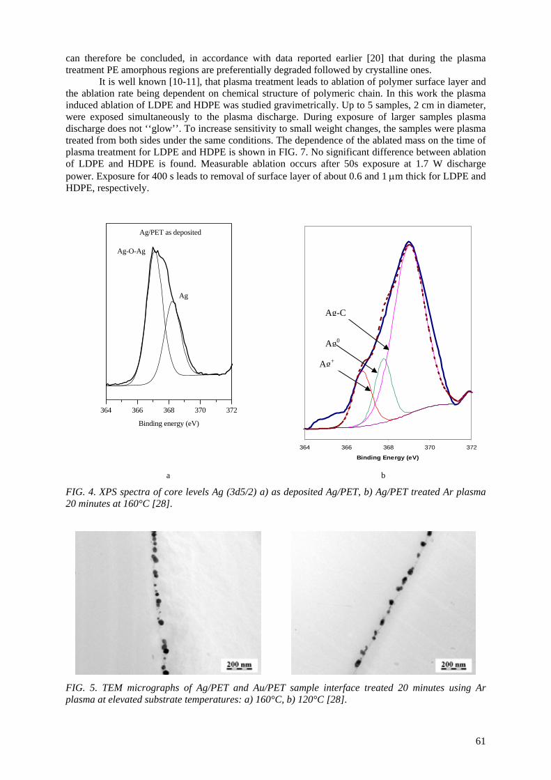
can therefore be concluded, in accordance with data reported earlier [20] that during the plasma treatment PE amorphous regions are preferentially degraded followed by crystalline ones.
It is well known [10-11], that plasma treatment leads to ablation of polymer surface layer and the ablation rate being dependent on chemical structure of polymeric chain. In this work the plasma induced ablation of LDPE and HDPE was studied gravimetrically. Up to 5 samples, 2 cm in diameter, were exposed simultaneously to the plasma discharge. During exposure of larger samples plasma discharge does not ‘‘glow’’. To increase sensitivity to small weight changes, the samples were plasma treated from both sides under the same conditions. The dependence of the ablated mass on the time of plasma treatment for LDPE and HDPE is shown in FIG. 7. No significant difference between ablation of LDPE and HDPE is found. Measurable ablation occurs after 50s exposure at 1.7 W discharge power. Exposure for 400 s leads to removal of surface layer of about 0.6 and 1 μm thick for LDPE and HDPE, respectively.
364 366 368 370 372
Binding energy (eV)
Ag-O-Ag
Ag/PET as deposited
Ag
a b
364 366 368 370 372
Binding Energy (eV)
Ag0
Ag+
Ag-C
FIG. 4. XPS spectra of core levels Ag (3d5/2) a) as deposited Ag/PET, b) Ag/PET treated Ar plasma 20 minutes at 160°C [28].
FIG. 5. TEM micrographs of Ag/PET and Au/PET sample interface treated 20 minutes using Ar plasma at elevated substrate temperatures: a) 160°C, b) 120°C [28].
61
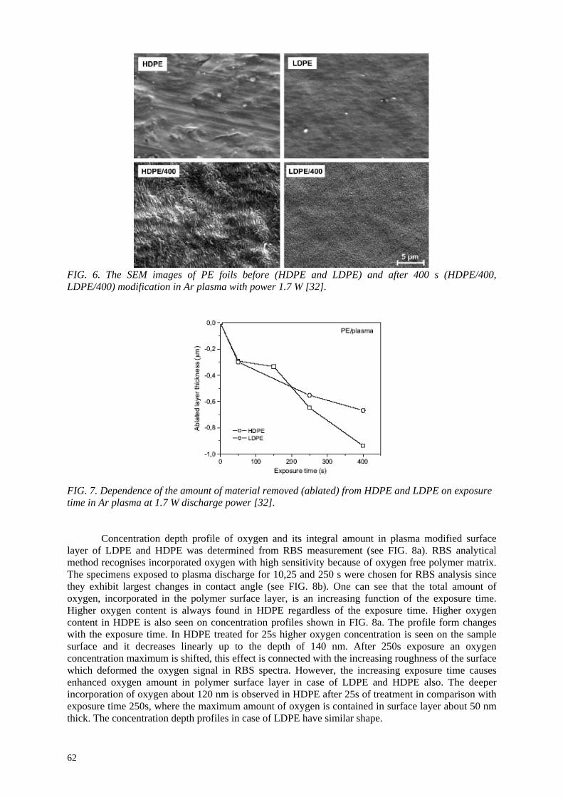
FIG. 6. The SEM images of PE foils before (HDPE and LDPE) and after 400 s (HDPE/400, LDPE/400) modification in Ar plasma with power 1.7 W [32].
FIG. 7. Dependence of the amount of material removed (ablated) from HDPE and LDPE on exposure time in Ar plasma at 1.7 W discharge power [32].
Concentration depth profile of oxygen and its integral amount in plasma modified surface layer of LDPE and HDPE was determined from RBS measurement (see FIG. 8a). RBS analytical method recognises incorporated oxygen with high sensitivity because of oxygen free polymer matrix. The specimens exposed to plasma discharge for 10,25 and 250 s were chosen for RBS analysis since they exhibit largest changes in contact angle (see FIG. 8b). One can see that the total amount of oxygen, incorporated in the polymer surface layer, is an increasing function of the exposure time. Higher oxygen content is always found in HDPE regardless of the exposure time. Higher oxygen content in HDPE is also seen on concentration profiles shown in FIG. 8a. The profile form changes with the exposure time. In HDPE treated for 25s higher oxygen concentration is seen on the sample surface and it decreases linearly up to the depth of 140 nm. After 250s exposure an oxygen concentration maximum is shifted, this effect is connected with the increasing roughness of the surface which deformed the oxygen signal in RBS spectra. However, the increasing exposure time causes enhanced oxygen amount in polymer surface layer in case of LDPE and HDPE also. The deeper incorporation of oxygen about 120 nm is observed in HDPE after 25s of treatment in comparison with exposure time 250s, where the maximum amount of oxygen is contained in surface layer about 50 nm thick. The concentration depth profiles in case of LDPE have similar shape.
62
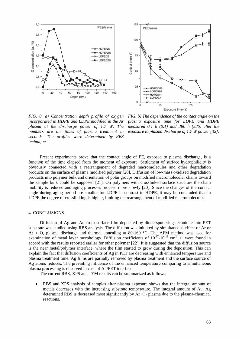
FIG. 8. a) Concentration depth profile of oxygen incorporated in HDPE and LDPE modified in the Ar plasma at the discharge power of 1.7 W. The numbers are the times of plasma treatment in seconds. The profiles were determined by RBS technique.
FIG. b) The dependence of the contact angle on the plasma exposure time for LDPE and HDPE measured 0.1 h (0.1) and 386 h (386) after the exposure to plasma discharge of 1.7 W power [32].
Present experiments prove that the contact angle of PE, exposed to plasma discharge, is a function of the time elapsed from the moment of exposure. Settlement of surface hydrophilicity is obviously connected with a rearrangement of degraded macromolecules and other degradation products on the surface of plasma modified polymer [20]. Diffusion of low-mass oxidized degradation products into polymer bulk and orientation of polar groups on modified macromolecular chains toward the sample bulk could be supposed [21]. On polymers with crosslinked surface structure the chain mobility is reduced and aging processes proceed more slowly [20]. Since the changes of the contact angle during aging period are smaller for LDPE in contrast to HDPE, it may be concluded that in LDPE the degree of crosslinking is higher, limiting the rearrangement of modified macromolecules.
4. CONCLUSIONS
Diffusion of Ag and Au from surface film deposited by diode-sputtering technique into PET substrate was studied using RBS analysis. The diffusion was initiated by simultaneous effect of Ar or Ar + O2 plasma discharge and thermal annealing at 80-160 °C. The AFM method was used for examination of metal layer morphology. Diffusion coefficients of 10-17-10-19 cm2 .s-1 were found in accord with the results reported earlier for other polymer [22]. It is suggested that the diffusion source is the near metal/polymer interface, where the film started to grow during the deposition. This can explain the fact that diffusion coefficients of Ag in PET are decreasing with enhanced temperature and plasma treatment time. Ag films are partially removed by plasma treatment and the surface source of Ag atoms reduces. The prevailing influence of the enhanced temperature comparing to simultaneous plasma processing is observed in case of Au/PET interface.
The current RBS, XPS and TEM results can be summarized as follows:
• RBS and XPS analysis of samples after plasma exposure shows that the integral amount of metals decreases with the increasing substrate temperature. The integral amount of Au, Ag determined RBS is decreased most significantly by Ar+O2 plasma due to the plasma-chemical reactions.
63
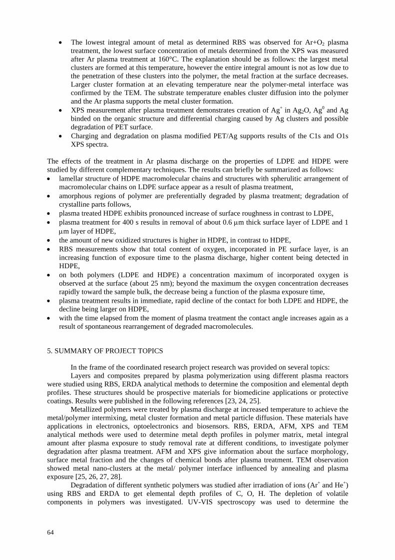
• The lowest integral amount of metal as determined RBS was observed for Ar+O2 plasma treatment, the lowest surface concentration of metals determined from the XPS was measured after Ar plasma treatment at 160°C. The explanation should be as follows: the largest metal clusters are formed at this temperature, however the entire integral amount is not as low due to the penetration of these clusters into the polymer, the metal fraction at the surface decreases. Larger cluster formation at an elevating temperature near the polymer-metal interface was confirmed by the TEM. The substrate temperature enables cluster diffusion into the polymer and the Ar plasma supports the metal cluster formation.
• XPS measurement after plasma treatment demonstrates creation of Ag+ in Ag2O, Ag0 and Ag binded on the organic structure and differential charging caused by Ag clusters and possible degradation of PET surface.
• Charging and degradation on plasma modified PET/Ag supports results of the C1s and O1s XPS spectra.
The effects of the treatment in Ar plasma discharge on the properties of LDPE and HDPE were studied by different complementary techniques. The results can briefly be summarized as follows: • lamellar structure of HDPE macromolecular chains and structures with spherulitic arrangement of
macromolecular chains on LDPE surface appear as a result of plasma treatment, • amorphous regions of polymer are preferentially degraded by plasma treatment; degradation of
crystalline parts follows, • plasma treated HDPE exhibits pronounced increase of surface roughness in contrast to LDPE, • plasma treatment for 400 s results in removal of about 0.6 μm thick surface layer of LDPE and 1
μm layer of HDPE, • the amount of new oxidized structures is higher in HDPE, in contrast to HDPE, • RBS measurements show that total content of oxygen, incorporated in PE surface layer, is an
increasing function of exposure time to the plasma discharge, higher content being detected in HDPE,
• on both polymers (LDPE and HDPE) a concentration maximum of incorporated oxygen is observed at the surface (about 25 nm); beyond the maximum the oxygen concentration decreases rapidly toward the sample bulk, the decrease being a function of the plasma exposure time,
• plasma treatment results in immediate, rapid decline of the contact for both LDPE and HDPE, the decline being larger on HDPE,
• with the time elapsed from the moment of plasma treatment the contact angle increases again as a result of spontaneous rearrangement of degraded macromolecules.
5. SUMMARY OF PROJECT TOPICS
In the frame of the coordinated research project research was provided on several topics: Layers and composites prepared by plasma polymerization using different plasma reactors
were studied using RBS, ERDA analytical methods to determine the composition and elemental depth profiles. These structures should be prospective materials for biomedicine applications or protective coatings. Results were published in the following references [23, 24, 25].
Metallized polymers were treated by plasma discharge at increased temperature to achieve the metal/polymer intermixing, metal cluster formation and metal particle diffusion. These materials have applications in electronics, optoelectronics and biosensors. RBS, ERDA, AFM, XPS and TEM analytical methods were used to determine metal depth profiles in polymer matrix, metal integral amount after plasma exposure to study removal rate at different conditions, to investigate polymer degradation after plasma treatment. AFM and XPS give information about the surface morphology, surface metal fraction and the changes of chemical bonds after plasma treatment. TEM observation showed metal nano-clusters at the metal/ polymer interface influenced by annealing and plasma exposure [25, 26, 27, 28].
Degradation of different synthetic polymers was studied after irradiation of ions (Ar+ and He+) using RBS and ERDA to get elemental depth profiles of C, O, H. The depletion of volatile components in polymers was investigated. UV-VIS spectroscopy was used to determine the
64
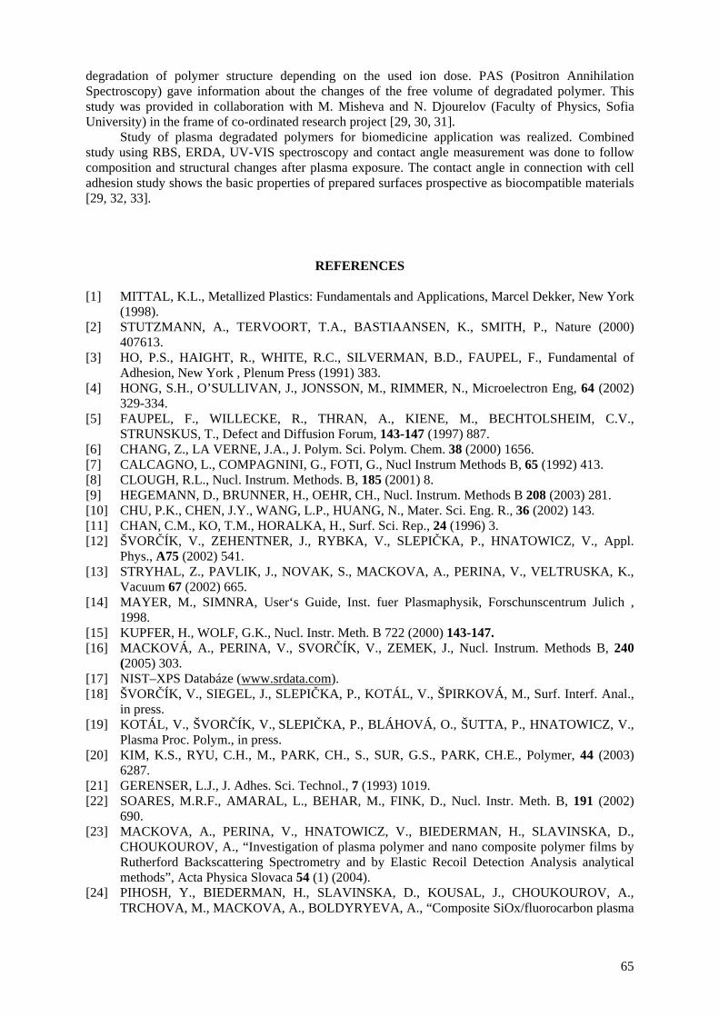
degradation of polymer structure depending on the used ion dose. PAS (Positron Annihilation Spectroscopy) gave information about the changes of the free volume of degradated polymer. This study was provided in collaboration with M. Misheva and N. Djourelov (Faculty of Physics, Sofia University) in the frame of co-ordinated research project [29, 30, 31].
Study of plasma degradated polymers for biomedicine application was realized. Combined study using RBS, ERDA, UV-VIS spectroscopy and contact angle measurement was done to follow composition and structural changes after plasma exposure. The contact angle in connection with cell adhesion study shows the basic properties of prepared surfaces prospective as biocompatible materials [29, 32, 33].
REFERENCES
[1] MITTAL, K.L., Metallized Plastics: Fundamentals and Applications, Marcel Dekker, New York
(1998). [2] STUTZMANN, A., TERVOORT, T.A., BASTIAANSEN, K., SMITH, P., Nature (2000)
407613. [3] HO, P.S., HAIGHT, R., WHITE, R.C., SILVERMAN, B.D., FAUPEL, F., Fundamental of
Adhesion, New York , Plenum Press (1991) 383. [4] HONG, S.H., O’SULLIVAN, J., JONSSON, M., RIMMER, N., Microelectron Eng, 64 (2002)
329-334. [5] FAUPEL, F., WILLECKE, R., THRAN, A., KIENE, M., BECHTOLSHEIM, C.V.,
STRUNSKUS, T., Defect and Diffusion Forum, 143-147 (1997) 887. [6] CHANG, Z., LA VERNE, J.A., J. Polym. Sci. Polym. Chem. 38 (2000) 1656. [7] CALCAGNO, L., COMPAGNINI, G., FOTI, G., Nucl Instrum Methods B, 65 (1992) 413. [8] CLOUGH, R.L., Nucl. Instrum. Methods. B, 185 (2001) 8. [9] HEGEMANN, D., BRUNNER, H., OEHR, CH., Nucl. Instrum. Methods B 208 (2003) 281. [10] CHU, P.K., CHEN, J.Y., WANG, L.P., HUANG, N., Mater. Sci. Eng. R., 36 (2002) 143. [11] CHAN, C.M., KO, T.M., HORALKA, H., Surf. Sci. Rep., 24 (1996) 3. [12] ŠVORČÍK, V., ZEHENTNER, J., RYBKA, V., SLEPIČKA, P., HNATOWICZ, V., Appl.
Phys., A75 (2002) 541. [13] STRYHAL, Z., PAVLIK, J., NOVAK, S., MACKOVA, A., PERINA, V., VELTRUSKA, K.,
Vacuum 67 (2002) 665. [14] MAYER, M., SIMNRA, User‘s Guide, Inst. fuer Plasmaphysik, Forschunscentrum Julich ,
1998. [15] KUPFER, H., WOLF, G.K., Nucl. Instr. Meth. B 722 (2000) 143-147. [16] MACKOVÁ, A., PERINA, V., SVORČÍK, V., ZEMEK, J., Nucl. Instrum. Methods B, 240
(2005) 303. [17] NIST–XPS Databáze (www.srdata.com). [18] ŠVORČÍK, V., SIEGEL, J., SLEPIČKA, P., KOTÁL, V., ŠPIRKOVÁ, M., Surf. Interf. Anal.,
in press. [19] KOTÁL, V., ŠVORČÍK, V., SLEPIČKA, P., BLÁHOVÁ, O., ŠUTTA, P., HNATOWICZ, V.,
Plasma Proc. Polym., in press. [20] KIM, K.S., RYU, C.H., M., PARK, CH., S., SUR, G.S., PARK, CH.E., Polymer, 44 (2003)
6287. [21] GERENSER, L.J., J. Adhes. Sci. Technol., 7 (1993) 1019. [22] SOARES, M.R.F., AMARAL, L., BEHAR, M., FINK, D., Nucl. Instr. Meth. B, 191 (2002)
690. [23] MACKOVA, A., PERINA, V., HNATOWICZ, V., BIEDERMAN, H., SLAVINSKA, D.,
CHOUKOUROV, A., “Investigation of plasma polymer and nano composite polymer films by Rutherford Backscattering Spectrometry and by Elastic Recoil Detection Analysis analytical methods”, Acta Physica Slovaca 54 (1) (2004).
[24] PIHOSH, Y., BIEDERMAN, H., SLAVINSKA, D., KOUSAL, J., CHOUKOUROV, A., TRCHOVA, M., MACKOVA, A., BOLDYRYEVA, A., “Composite SiOx/fluorocarbon plasma
65
polymer films prepared by r.f. Magnetron sputtering of SiO2 and PTFE“, Vacuum 81 (1) (2006) 38-44.
[25] MACKOVA, A., “Radiation modified synthetic polymers for application in medicine“, Internal Report of the 1st RCM, p. 80-88, 8-11 December 2003, Vienna, Austria.
[26] MACKOVA, A., PERINA, V., SVORCIK, V., ZEMEK, J., “RBS, ERDA and XPS study of Ag and Cu diffusion in PET and PI polymer foils“, Nuclear Instruments & Methods B, 240 (1-2) (2005) 303-307.
[27] MACKOVA, A., SVORCIK, V., STRYHAL, Z., et al., “RBS and AFM study of Ag and Au diffusion into PET foils influenced by plasma treatment“, Surface And Interface Analysis 38 (4) (2006) 335-338.
[28] MACKOVÁ, A., ŠVORČÍK, V., SAJDL, P., STRÝHAL, Z., PAVLÍK, J., MALINSKÝ, P., ŠLOUF, M., “RBS, XPS and TEM Study of Metal and Polymer Interface Modified by Plasma Treatment“, Book of abstracts, p. 95, Joint Vacuum Conference 11, September 24-28, 2006, Prague, Czech Republic.
[29] MACKOVA, A., BOLDYRYEVA, H., “Analysis of plasma polymers and conventional polymers Modified by various Techniques“, Internal Report of the 2st RCM, p. 37-47, 11-15 July 2005, Madrid, Spain.
[30] POPOK, V.N., AZARKO, I.I., KHAIBULLIN, R.I., STEPANOV, A.L., HNATOWICZ, V., MACKOVA, A., PRASALOVICH, S.V., “Radiation-induced change of polyimide properties under high-fluence and high ion current density implantation“, Appl. Phys. A, 78 (2004) 1067-1072.
[31] MACKOVA, A., HAVRANEK, V., SVORCIK, V., DJOURELOV, A., SUZUKI, T., “Degradation of PET, PEEK and PI induced by irradiation with 150 keV Ar+ and 1.76 MeV He+ ions“, Nuclear Instruments & Methods B, 240 (1-2) (2005) 245-249.
[32] ŠVORČÍK, V., KOLÁŘOVÁ, J., SLEPIČKA, P., MACKOVÁ, A., NOVOTNÁ, M., HNATOWICZ, V., “Modification of surface properties of high and low density polyethylene by Ar plasma discharge“, Polymer Degradation And Stability, 91 (6) (2006) 1219-1225.
[33] ŠVORČÍK, V., SLEPIČKA, P., DVOŘÁNKOVÁ, B., MACKOVÁ, A., HNATOWICZ, V., “Structural, chemical and biological properties of carbon layers sputtered on polyethyleneterephtalate”, Journal of Materials Science - Materials in Medicine. 17 (3) (2006) 229-234.
66

CONTROLLING OF DEGRADATION EFFECTS IN RADIATION PROCESSING OF POLYMERS E.A. HEGAZY, H. ABDEL-REHIM, D.A. DIAA, A. EL-BARBARY National Center for Radiation Research and Technology Atomic Energy Authority, Cairo, Egypt
Abstract Radiation induced degradation technology is a new and promising application of ionizing radiation to
develop viscose, pulp, paper, food preservation, pharmaceutical production, and natural bioactive agents industries. Controlling the degree of degradation, uniform molecular weight distribution, saving achieved in the chemicals (used in conventional methods) on a cost basis, and environmentally friendly process are the beneficial effects of using radiation technology in these industries. However, for some development countries such technology is not economic. Therefore, a great effort should be done to reduce the cost required for such technologies. One of the principle factors for reducing the cost is achieving the degradation at low irradiation doses. The addition of some additives such as potassium per-sulfate (KPS), ammonium per-sulfate (APS), or H2O2 to natural polymers (carboxy-methylcellulose (CMC), chitosan, carageenan and Na-alginate) during irradiation process accelerates their degradation. The highest degradation rate of polysaccharides obtained when APS was used. The end product of irradiated CMC, chitosan, carageenan and Na-alginate may be used as food additive or benefited in agricultural purposes. On the other hand, radiation crosslinking of PAAm or PNIPAAm is affected by the presence of natural polymer like CMC-Na and carageenan due to their degradability which could be controlled according to its concentration in the bulk medium and irradiation dose. Accordingly, the gel content, thermo-sensitivity (LCST) and swelling properties of PNIPAAm based natural polymers could be controlled. The swelling of the prepared copolymer hydrogels was investigated for its possible use in personal care articles particularly diapers or as carriers for drug delivery systems. The prepared crosslinked copolymers possessed high and fast swelling properties in simulated urine media and the swelling ratios of CMC-Na /PAAm gels in urine are acceptable for diaper application.
1. INTRODUCTION
When organic materials are irradiated by ionizing radiation, they are divided into two types, degradation (chain scission) and chain link (crosslinking). Interest in radiation degradation chemistry of natural and synthetic polymers has increased tremendously as the potential was recognized for using radiation to improve industrial process such as pulping, viscose, cosmetics and food preservation and new natural active agents. Possibilities for using radiation in degradation include; Natural polysaccharides with high molecular weight like alginate and chitosan, which are found in seaweed and crustaceans and are widely utilized in food, pharmaceutical and bioengineering industries. A new class of biologically active compounds of polymer type, as well as the technology for overall protection of food products, has been developed. Recently, oligosaccharides derived from the depolymerization of polysaccharides by enzyme reaction were shown to have novel features such as the enhancement of antibiosis, promotion of germination and root elongation of plants. Radiation-induced depolymerization caused by chain scission was successfully used for such purposes and has been tested and implemented in the industry. Moreover, new food protection technology has been proposed, using active polymer coatings and packages (prepared by radiation method) with improved barrier and bactericidal properties.
Degradation is a very important reaction in the chemistry of high-molecular-weight
compounds. It is used for determining the structure of polymeric compounds, and obtaining valuable low molecular weight substances from natural polymers. Sometimes degradation is used to lower the molecular weight of polymers partially to facilitate fabrication. The splitting of polymeric macromolecules to form free radicals is employed for synthesizing modified polymers. At the same time polymer degradation may often be considered as an undesirable side reaction occurring during the chemical transformation, fabrication and usage of polymers.
67
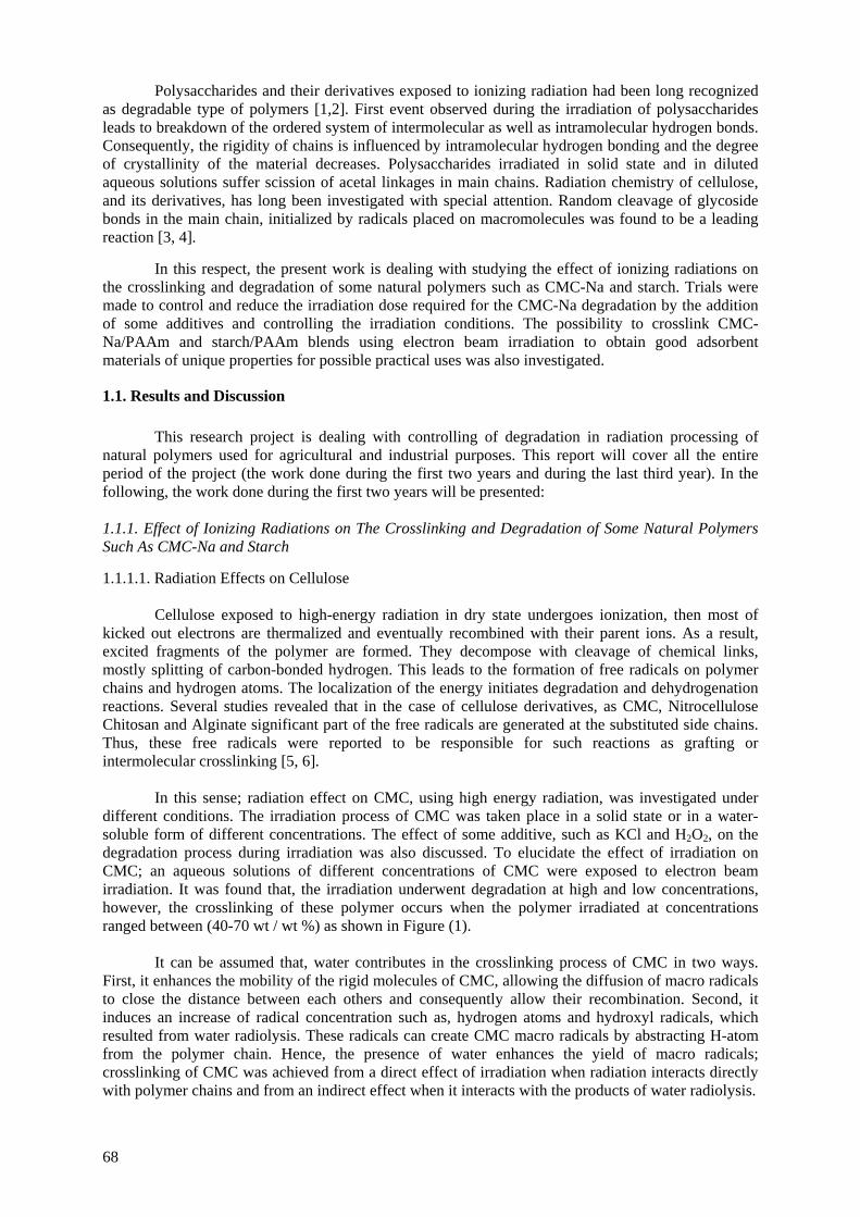
Polysaccharides and their derivatives exposed to ionizing radiation had been long recognized as degradable type of polymers [1,2]. First event observed during the irradiation of polysaccharides leads to breakdown of the ordered system of intermolecular as well as intramolecular hydrogen bonds. Consequently, the rigidity of chains is influenced by intramolecular hydrogen bonding and the degree of crystallinity of the material decreases. Polysaccharides irradiated in solid state and in diluted aqueous solutions suffer scission of acetal linkages in main chains. Radiation chemistry of cellulose, and its derivatives, has long been investigated with special attention. Random cleavage of glycoside bonds in the main chain, initialized by radicals placed on macromolecules was found to be a leading reaction [3, 4].
In this respect, the present work is dealing with studying the effect of ionizing radiations on
the crosslinking and degradation of some natural polymers such as CMC-Na and starch. Trials were made to control and reduce the irradiation dose required for the CMC-Na degradation by the addition of some additives and controlling the irradiation conditions. The possibility to crosslink CMC-Na/PAAm and starch/PAAm blends using electron beam irradiation to obtain good adsorbent materials of unique properties for possible practical uses was also investigated.
1.1. Results and Discussion This research project is dealing with controlling of degradation in radiation processing of
natural polymers used for agricultural and industrial purposes. This report will cover all the entire period of the project (the work done during the first two years and during the last third year). In the following, the work done during the first two years will be presented: 1.1.1. Effect of Ionizing Radiations on The Crosslinking and Degradation of Some Natural Polymers Such As CMC-Na and Starch 1.1.1.1. Radiation Effects on Cellulose
Cellulose exposed to high-energy radiation in dry state undergoes ionization, then most of kicked out electrons are thermalized and eventually recombined with their parent ions. As a result, excited fragments of the polymer are formed. They decompose with cleavage of chemical links, mostly splitting of carbon-bonded hydrogen. This leads to the formation of free radicals on polymer chains and hydrogen atoms. The localization of the energy initiates degradation and dehydrogenation reactions. Several studies revealed that in the case of cellulose derivatives, as CMC, Nitrocellulose Chitosan and Alginate significant part of the free radicals are generated at the substituted side chains. Thus, these free radicals were reported to be responsible for such reactions as grafting or intermolecular crosslinking [5, 6].
In this sense; radiation effect on CMC, using high energy radiation, was investigated under different conditions. The irradiation process of CMC was taken place in a solid state or in a water-soluble form of different concentrations. The effect of some additive, such as KCl and H2O2, on the degradation process during irradiation was also discussed. To elucidate the effect of irradiation on CMC; an aqueous solutions of different concentrations of CMC were exposed to electron beam irradiation. It was found that, the irradiation underwent degradation at high and low concentrations, however, the crosslinking of these polymer occurs when the polymer irradiated at concentrations ranged between (40-70 wt / wt %) as shown in Figure (1).
It can be assumed that, water contributes in the crosslinking process of CMC in two ways.
First, it enhances the mobility of the rigid molecules of CMC, allowing the diffusion of macro radicals to close the distance between each others and consequently allow their recombination. Second, it induces an increase of radical concentration such as, hydrogen atoms and hydroxyl radicals, which resulted from water radiolysis. These radicals can create CMC macro radicals by abstracting H-atom from the polymer chain. Hence, the presence of water enhances the yield of macro radicals; crosslinking of CMC was achieved from a direct effect of irradiation when radiation interacts directly with polymer chains and from an indirect effect when it interacts with the products of water radiolysis.
68
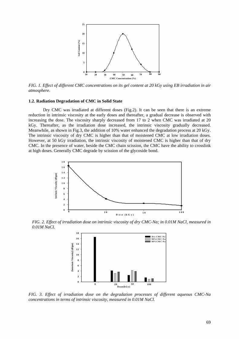
CMC Concentration (%)G
el C
onte
nt (%
)
0
5
10
15
20
25
10 20 30 40 50 60 70 80 90
FIG. 1. Effect of different CMC concentrations on its gel content at 20 kGy using EB irradiation in air atmosphere. 1.2. Radiation Degradation of CMC in Solid State
Dry CMC was irradiated at different doses (Fig.2). It can be seen that there is an extreme reduction in intrinsic viscosity at the early doses and thereafter, a gradual decrease is observed with increasing the dose. The viscosity sharply decreased from 17 to 2 when CMC was irradiated at 20 kGy. Thereafter, as the irradiation dose increased, the intrinsic viscosity gradually decreased. Meanwhile, as shown in Fig.3, the addition of 10% water enhanced the degradation process at 20 kGy. The intrinsic viscosity of dry CMC is higher than that of moistened CMC at low irradiation doses. However, at 50 kGy irradiation, the intrinsic viscosity of moistened CMC is higher than that of dry CMC. In the presence of water, beside the CMC chain scission, the CMC have the ability to crosslink at high doses. Generally CMC degrade by scission of the glycoside bond.
D o s e ( k G y )
Intr
insi
c V
isco
sity
(dl/g
m)
0
2
4
6
8
1 0
1 2
1 4
1 6
1 8
0 2 0 5 0 1 0 0
FIG. 2. Effect of irradiation dose on intrinsic viscosity of dry CMC-Na; in 0.01M NaCl, measured in 0.01M NaCl.
D ose(kG y)
[Int
erin
sic
Visc
osity
] (dl
/gm
)
0
2
4
6
8
10
12
14
16
18D ry C M C -N a 90% C M C -N a80% C M C -N a
0 20 50 100
FIG. 3. Effect of irradiation dose on the degradation processes of different aqueous CMC-Na concentrations in terms of intrinsic viscosity, measured in 0.01M NaCl.
69
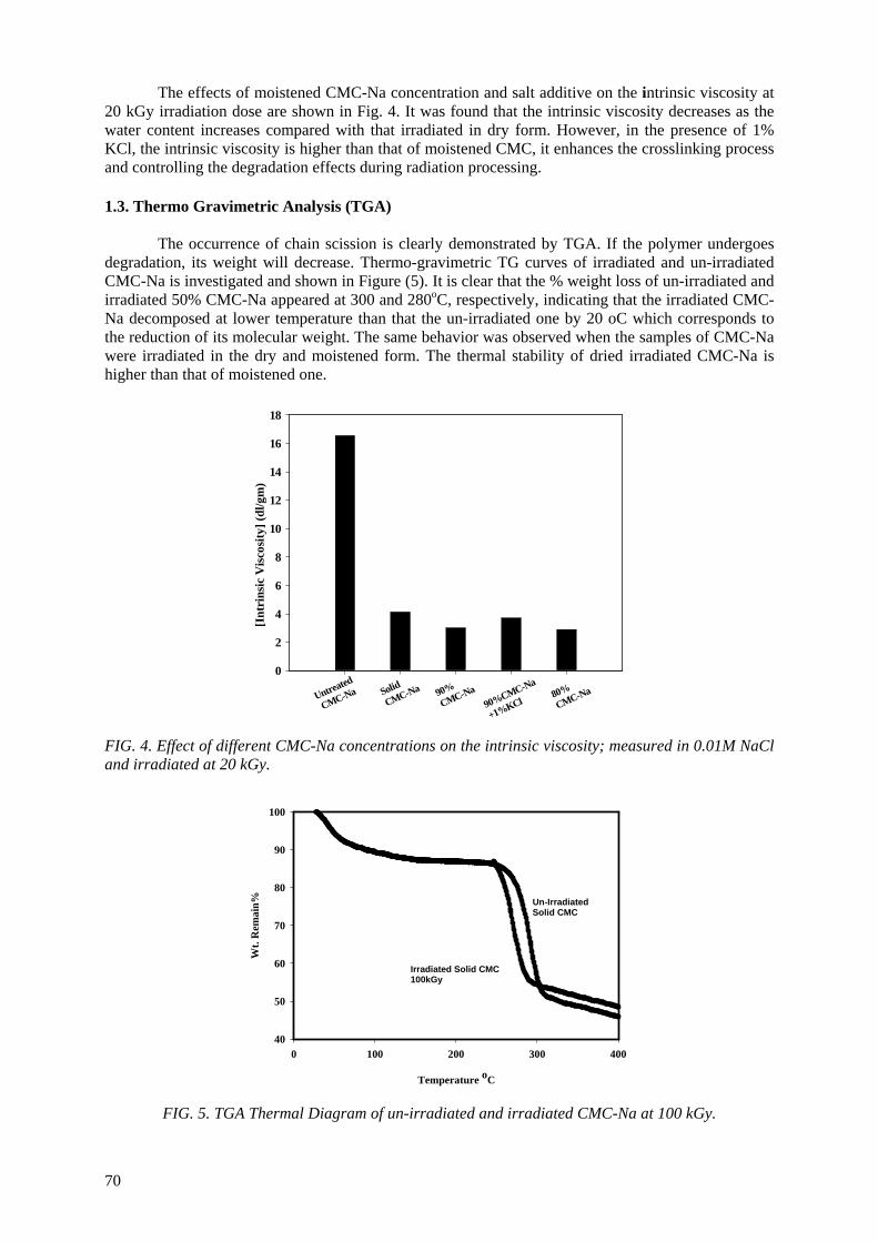
The effects of moistened CMC-Na concentration and salt additive on the intrinsic viscosity at 20 kGy irradiation dose are shown in Fig. 4. It was found that the intrinsic viscosity decreases as the water content increases compared with that irradiated in dry form. However, in the presence of 1% KCl, the intrinsic viscosity is higher than that of moistened CMC, it enhances the crosslinking process and controlling the degradation effects during radiation processing.
1.3. Thermo Gravimetric Analysis (TGA)
The occurrence of chain scission is clearly demonstrated by TGA. If the polymer undergoes degradation, its weight will decrease. Thermo-gravimetric TG curves of irradiated and un-irradiated CMC-Na is investigated and shown in Figure (5). It is clear that the % weight loss of un-irradiated and irradiated 50% CMC-Na appeared at 300 and 280oC, respectively, indicating that the irradiated CMC-Na decomposed at lower temperature than that the un-irradiated one by 20 oC which corresponds to the reduction of its molecular weight. The same behavior was observed when the samples of CMC-Na were irradiated in the dry and moistened form. The thermal stability of dried irradiated CMC-Na is higher than that of moistened one.
[Int
rins
ic V
isco
sity
] (dl
/gm
)
0
2
4
6
8
10
12
14
16
18
Untreated
CMC-Na Solid
CMC-Na 90%
CMC-Na90%CMC-Na
+1%KCl80%CMC-Na
FIG. 4. Effect of different CMC-Na concentrations on the intrinsic viscosity; measured in 0.01M NaCl and irradiated at 20 kGy.
Irradiated Solid CMC 100kGy
Un-irradiated Solid CMC
Temperature oC
0 100 200 300 400
Wt.
Rem
ain%
40
50
60
70
80
90
100
Un-Irradiated Solid CMC
Irradiated Solid CMC 100kGy
FIG. 5. TGA Thermal Diagram of un-irradiated and irradiated CMC-Na at 100 kGy.
70
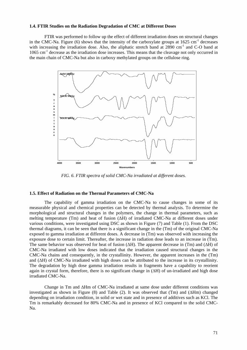
1.4. FTIR Studies on the Radiation Degradation of CMC at Different Doses
FTIR was performed to follow up the effect of different irradiation doses on structural changes in the CMC-Na. Figure (6) shows that the intensity of the carboxylate groups at 1625 cm-1 decreases with increasing the irradiation dose. Also, the aliphatic stretch band at 2890 cm-1 and C-O band at 1065 cm-1 decrease as the irradiation dose increases. This means that the cleavage not only occurred in the main chain of CMC-Na but also in carboxy methylated groups on the cellulose ring.
SOLID 20kGy
SOLID 50kGy
Solid 100kGy
5001000150020002500300035004000
Wavenumbers
% Transmittance
FIG. 6. FTIR spectra of solid CMC-Na irradiated at different doses.
1.5. Effect of Radiation on the Thermal Parameters of CMC-Na The capability of gamma irradiation on the CMC-Na to cause changes in some of its measurable physical and chemical properties can be detected by thermal analysis. To determine the morphological and structural changes in the polymers, the change in thermal parameters, such as melting temperature (Tm) and heat of fusion (ΔH) of irradiated CMC-Na at different doses under various conditions, were investigated using DSC as shown in Figure (7) and Table (1). From the DSC thermal diagrams, it can be seen that there is a significant change in the (Tm) of the original CMC-Na exposed to gamma irradiation at different doses. A decrease in (Tm) was observed with increasing the exposure dose to certain limit. Thereafter, the increase in radiation dose leads to an increase in (Tm). The same behavior was observed for heat of fusion (ΔH). The apparent decrease in (Tm) and (∆H) of CMC-Na irradiated with low doses indicated that the irradiation caused structural changes in the CMC-Na chains and consequently, in the crystallinity. However, the apparent increases in the (Tm) and (∆H) of CMC-Na irradiated with high doses can be attributed to the increase in its crystallinity. The degradation by high dose gamma irradiation results in fragments have a capability to reorient again in crystal form, therefore, there is no significant change in (∆H) of un-irradiated and high dose irradiated CMC-Na. Change in Tm and ∆Hm of CMC-Na irradiated at same dose under different conditions was investigated as shown in Figure (8) and Table (2). It was observed that (Tm) and (∆Hm) changed depending on irradiation condition, in solid or wet state and in presence of additives such as KCl. The Tm is remarkably decreased for 80% CMC-Na and in presence of KCl compared to the solid CMC-Na.
71
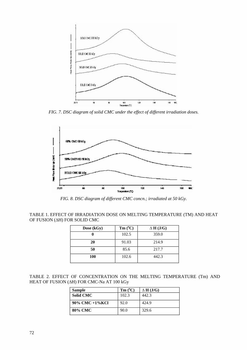
FIG. 7. DSC diagram of solid CMC under the effect of different irradiation doses.
FIG. 8. DSC diagram of different CMC concn.; irradiated at 50 kGy.
TABLE 1. EFFECT OF IRRADIATION DOSE ON MELTING TEMPERATURE (TM) AND HEAT OF FUSION (∆H) FOR SOLID CMC
Dose (kGy) Tm (oC) ∆ H (J/G) 0 102.5 359.0
20 91.03 214.9
50 85.6 217.7
100 102.6 442.3
TABLE 2. EFFECT OF CONCENTRATION ON THE MELTING TEMPERATURE (Tm) AND HEAT OF FUSION (∆H) FOR CMC-Na AT 100 kGy
Sample Tm (oC) ∆ H (J/G) Solid CMC 102.3 442.3
90% CMC +1%KCl 92.0 424.9
80% CMC 90.0 329.6
72
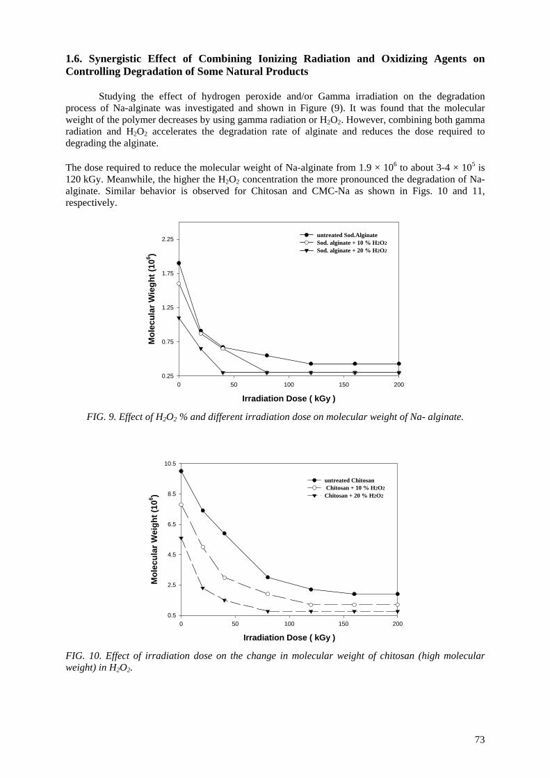
1.6. Synergistic Effect of Combining Ionizing Radiation and Oxidizing Agents on Controlling Degradation of Some Natural Products Studying the effect of hydrogen peroxide and/or Gamma irradiation on the degradation process of Na-alginate was investigated and shown in Figure (9). It was found that the molecular weight of the polymer decreases by using gamma radiation or H2O2. However, combining both gamma radiation and H2O2 accelerates the degradation rate of alginate and reduces the dose required to degrading the alginate. The dose required to reduce the molecular weight of Na-alginate from 1.9 × 10⁶ to about 3-4 × 10⁵ is 120 kGy. Meanwhile, the higher the H2O2 concentration the more pronounced the degradation of Na- alginate. Similar behavior is observed for Chitosan and CMC-Na as shown in Figs. 10 and 11, respectively.
Irradiation Dose ( kGy )0 50 100 150 200
Mol
ecul
ar W
iegh
t (10
6 )
0.25
0.75
1.25
1.75
2.25untreated Sod.Alginate Sod. alginate + 10 % H2O2Sod. alginate + 20 % H2O2
FIG. 9. Effect of H2O2 % and different irradiation dose on molecular weight of Na- alginate.
Irradiation Dose ( kGy )0 50 100 150 200
Mol
ecul
ar W
eigh
t (10
6 )
0.5
2.5
4.5
6.5
8.5
10.5
untreated Chitosan Chitosan + 10 % H2O2Chitosan + 20 % H2O2
FIG. 10. Effect of irradiation dose on the change in molecular weight of chitosan (high molecular weight) in H2O2.
73
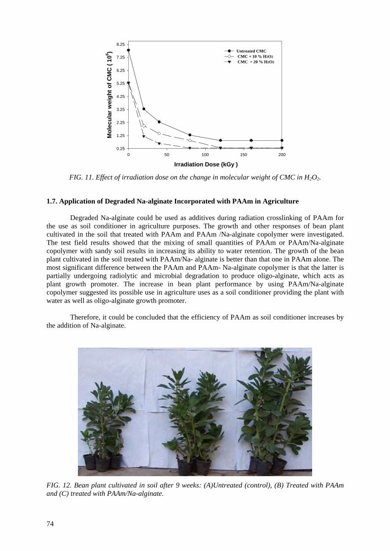
Irradiation Dose (kGy )0 50 100 150 200
Mol
ecul
ar w
eigh
t of C
MC
( 10
6 )
0.25
1.25
2.25
3.25
4.25
5.25
6.25
7.25
8.25Untreated CMC CMC + 10 % H2O2 CMC + 20 % H2O2
FIG. 11. Effect of irradiation dose on the change in molecular weight of CMC in H2O2.
1.7. Application of Degraded Na-alginate Incorporated with PAAm in Agriculture
Degraded Na-alginate could be used as additives during radiation crosslinking of PAAm for the use as soil conditioner in agriculture purposes. The growth and other responses of bean plant cultivated in the soil that treated with PAAm and PAAm /Na-alginate copolymer were investigated. The test field results showed that the mixing of small quantities of PAAm or PAAm/Na-alginate copolymer with sandy soil results in increasing its ability to water retention. The growth of the bean plant cultivated in the soil treated with PAAm/Na- alginate is better than that one in PAAm alone. The most significant difference between the PAAm and PAAm- Na-alginate copolymer is that the latter is partially undergoing radiolytic and microbial degradation to produce oligo-alginate, which acts as plant growth promoter. The increase in bean plant performance by using PAAm/Na-alginate copolymer suggested its possible use in agriculture uses as a soil conditioner providing the plant with water as well as oligo-alginate growth promoter.
Therefore, it could be concluded that the efficiency of PAAm as soil conditioner increases by
the addition of Na-alginate.
FIG. 12. Bean plant cultivated in soil after 9 weeks: (A)Untreated (control), (B) Treated with PAAm and (C) treated with PAAm/Na-alginate.
74
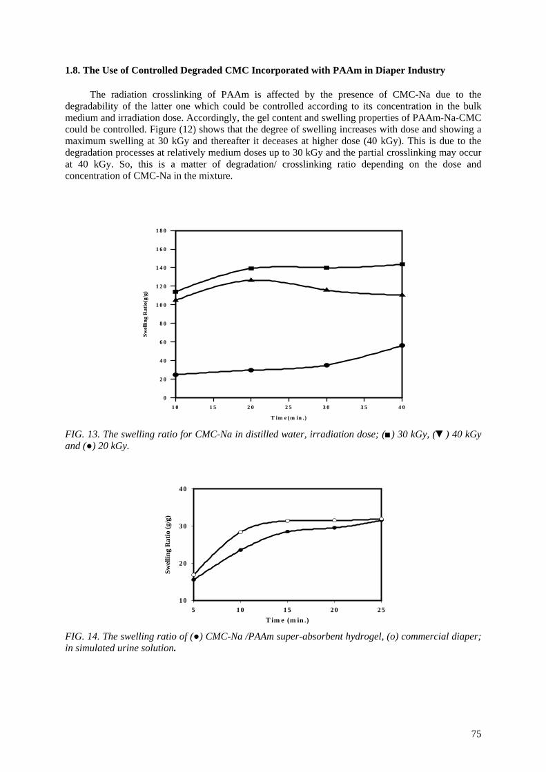
1.8. The Use of Controlled Degraded CMC Incorporated with PAAm in Diaper Industry
The radiation crosslinking of PAAm is affected by the presence of CMC-Na due to the degradability of the latter one which could be controlled according to its concentration in the bulk medium and irradiation dose. Accordingly, the gel content and swelling properties of PAAm-Na-CMC could be controlled. Figure (12) shows that the degree of swelling increases with dose and showing a maximum swelling at 30 kGy and thereafter it deceases at higher dose (40 kGy). This is due to the degradation processes at relatively medium doses up to 30 kGy and the partial crosslinking may occur at 40 kGy. So, this is a matter of degradation/ crosslinking ratio depending on the dose and concentration of CMC-Na in the mixture.
T im e (m in .)
1 0 1 5 2 0 2 5 3 0 3 5 4 0
Swel
ling
Rat
io(g
/g)
0
2 0
4 0
6 0
8 0
1 0 0
1 2 0
1 4 0
1 6 0
1 8 0
FIG. 13. The swelling ratio for CMC-Na in distilled water, irradiation dose; (■) 30 kGy, (▼) 40 kGy and (●) 20 kGy.
T im e (m in .)5 10 15 20 25
Swel
ling
Rat
io (g
/g)
1 0
20
30
40
FIG. 14. The swelling ratio of (●) CMC-Na /PAAm super-absorbent hydrogel, (o) commercial diaper; in simulated urine solution.
75
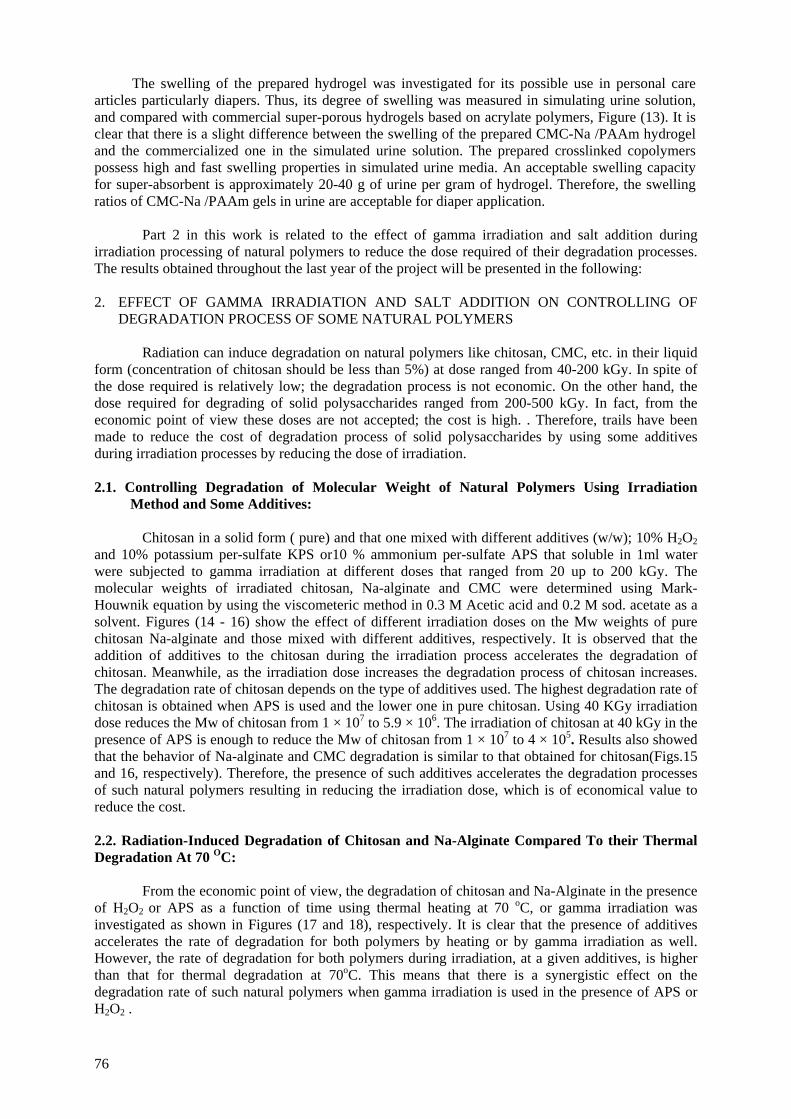
The swelling of the prepared hydrogel was investigated for its possible use in personal care articles particularly diapers. Thus, its degree of swelling was measured in simulating urine solution, and compared with commercial super-porous hydrogels based on acrylate polymers, Figure (13). It is clear that there is a slight difference between the swelling of the prepared CMC-Na /PAAm hydrogel and the commercialized one in the simulated urine solution. The prepared crosslinked copolymers possess high and fast swelling properties in simulated urine media. An acceptable swelling capacity for super-absorbent is approximately 20-40 g of urine per gram of hydrogel. Therefore, the swelling ratios of CMC-Na /PAAm gels in urine are acceptable for diaper application.
Part 2 in this work is related to the effect of gamma irradiation and salt addition during
irradiation processing of natural polymers to reduce the dose required of their degradation processes. The results obtained throughout the last year of the project will be presented in the following: 2. EFFECT OF GAMMA IRRADIATION AND SALT ADDITION ON CONTROLLING OF
DEGRADATION PROCESS OF SOME NATURAL POLYMERS
Radiation can induce degradation on natural polymers like chitosan, CMC, etc. in their liquid form (concentration of chitosan should be less than 5%) at dose ranged from 40-200 kGy. In spite of the dose required is relatively low; the degradation process is not economic. On the other hand, the dose required for degrading of solid polysaccharides ranged from 200-500 kGy. In fact, from the economic point of view these doses are not accepted; the cost is high. . Therefore, trails have been made to reduce the cost of degradation process of solid polysaccharides by using some additives during irradiation processes by reducing the dose of irradiation. 2.1. Controlling Degradation of Molecular Weight of Natural Polymers Using Irradiation
Method and Some Additives:
Chitosan in a solid form ( pure) and that one mixed with different additives (w/w); 10% H2O2 and 10% potassium per-sulfate KPS or10 % ammonium per-sulfate APS that soluble in 1ml water were subjected to gamma irradiation at different doses that ranged from 20 up to 200 kGy. The molecular weights of irradiated chitosan, Na-alginate and CMC were determined using Mark-Houwnik equation by using the viscometeric method in 0.3 M Acetic acid and 0.2 M sod. acetate as a solvent. Figures (14 - 16) show the effect of different irradiation doses on the Mw weights of pure chitosan Na-alginate and those mixed with different additives, respectively. It is observed that the addition of additives to the chitosan during the irradiation process accelerates the degradation of chitosan. Meanwhile, as the irradiation dose increases the degradation process of chitosan increases. The degradation rate of chitosan depends on the type of additives used. The highest degradation rate of chitosan is obtained when APS is used and the lower one in pure chitosan. Using 40 KGy irradiation dose reduces the Mw of chitosan from 1 × 10⁷ to 5.9 × 10⁶. The irradiation of chitosan at 40 kGy in the presence of APS is enough to reduce the Mw of chitosan from 1 × 10⁷ to 4 × 10⁵. Results also showed that the behavior of Na-alginate and CMC degradation is similar to that obtained for chitosan(Figs.15 and 16, respectively). Therefore, the presence of such additives accelerates the degradation processes of such natural polymers resulting in reducing the irradiation dose, which is of economical value to reduce the cost.
2.2. Radiation-Induced Degradation of Chitosan and Na-Alginate Compared To their Thermal Degradation At 70 OC: From the economic point of view, the degradation of chitosan and Na-Alginate in the presence of H2O2 or APS as a function of time using thermal heating at 70 oC, or gamma irradiation was investigated as shown in Figures (17 and 18), respectively. It is clear that the presence of additives accelerates the rate of degradation for both polymers by heating or by gamma irradiation as well. However, the rate of degradation for both polymers during irradiation, at a given additives, is higher than that for thermal degradation at 70oC. This means that there is a synergistic effect on the degradation rate of such natural polymers when gamma irradiation is used in the presence of APS or H2O2 .
76
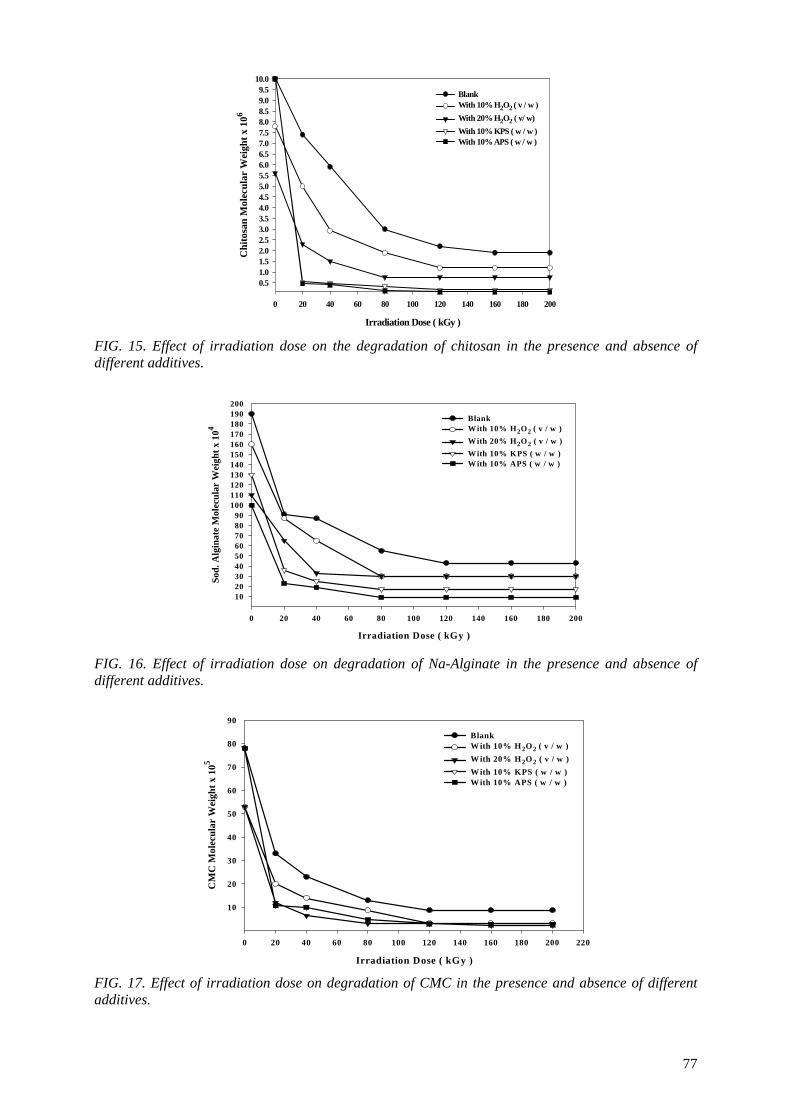
Irradiation Dose ( kGy )
0 20 40 60 80 100 120 140 160 180 200
Chi
tosa
n M
olec
ular
Wei
ght x
106
0.51.01.52.02.53.03.54.04.55.05.56.06.57.07.58.08.59.09.5
10.0
Blank With 10% H2O2 ( v / w )With 20% H2O2 ( v/ w)With 10% KPS ( w / w )With 10% APS ( w / w )
FIG. 15. Effect of irradiation dose on the degradation of chitosan in the presence and absence of different additives.
Irradiation Dose ( kGy )
0 20 40 60 80 100 120 140 160 180 200
Sod.
Alg
inat
e M
olec
ular
Wei
ght x
104
102030405060708090
100110120130140150160170180190200
Blank With 10% H2O2 ( v / w )With 20% H2O2 ( v / w )With 10% KPS ( w / w )With 10% APS ( w / w )
FIG. 16. Effect of irradiation dose on degradation of Na-Alginate in the presence and absence of different additives.
Irradiation Dose ( kGy )
0 20 40 60 80 100 120 140 160 180 200 220
CM
C M
olec
ular
Wei
ght x
105
10
20
30
40
50
60
70
80
90
Blank W ith 10% H2O2 ( v / w )W ith 20% H2O2 ( v / w )W ith 10% KPS ( w / w )W ith 10% APS ( w / w )
FIG. 17. Effect of irradiation dose on degradation of CMC in the presence and absence of different additives.
77
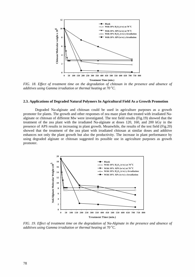
Treatment Time (min.)
0 50 100 150 200 250 300 350 400 450 500 550 600 650 700 750 800
Chi
tosa
n M
olec
ular
wei
ght x
106
0
2
4
6
8
10
12
BlankWith 10% H2O2 (v/w) at 70 oC
With 10% APS (w/w) at 70 oCWith 10% H2O2 (v/w) γ-Irradiation
With 10% APS (w/w) γ-Irradiation
FIG. 18. Effect of treatment time on the degradation of chitosan in the presence and absence of additives using Gamma irradiation or thermal heating at 70 oC. 2.3. Applications of Degraded Natural Polymers In Agricultural Field As a Growth Promotion
Degraded Na-alginate and chitosan could be used in agriculture purposes as a growth promoter for plants. The growth and other responses of zea maze plant that treated with irradiated Na-alginate or chitosan of different Mw were investigated. The test field results (Fig.19) showed that the treatment of the zea plant with the irradiated Na-alginate at doses 120, 160, and 200 kGy in the presence of APS results in increasing in plant growth. Meanwhile, the results of the test field (Fig.20) showed that the treatment of the zea plant with irradiated chitosan at similar doses and additive enhances not only the plant growth but also the productivity. The increase in plant performance by using degraded alginate or chitosan suggested its possible use in agriculture purposes as growth promoter.
Treatment Time (min.)
0 50 100 150 200 250 300 350 400 450 500 550 600 650 700 750 800
Sod.
Alg
inat
e M
olec
ular
Wei
ght x
105
0
2
4
6
8
10
12
14
16
18
20
Blank With 10% H2O2 (v/w) at 70 oC
With 10% APS (w/w) at 70 oCWith 10% H2O2 (v/w) γ-Irradiation
With 10% APs (w/w) γ-Irradiation
FIG. 19. Effect of treatment time on the degradation of Na-Alginate in the presence and absence of additives using Gamma irradiation or thermal heating at 70 oC.
78
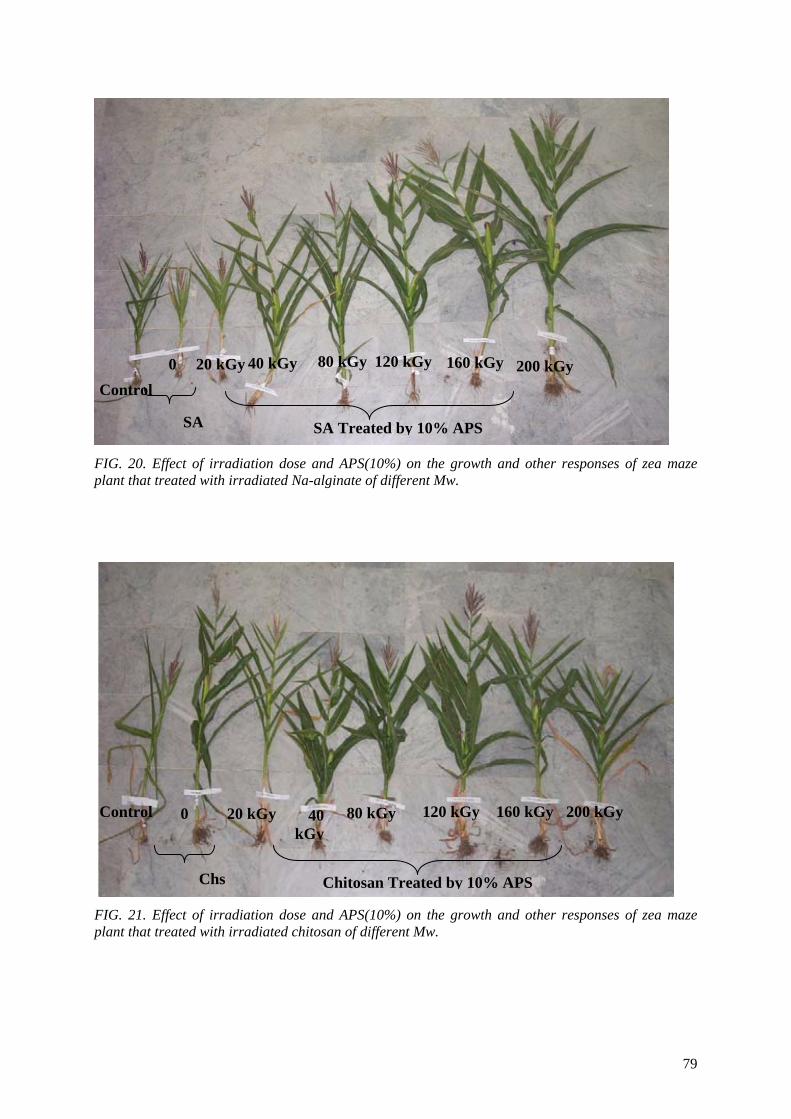
40 kGy 20 kGy 200 kGy 160 kGy 120 kGy 80 kGy 0 Control
SA Treated by 10% APS SA
FIG. 20. Effect of irradiation dose and APS(10%) on the growth and other responses of zea maze plant that treated with irradiated Na-alginate of different Mw.
Control 120 kGy 160 kGy 200 kGy 80 kGy 0 20 kGy 40 kGy
Chitosan Treated by 10% APS Chs
FIG. 21. Effect of irradiation dose and APS(10%) on the growth and other responses of zea maze plant that treated with irradiated chitosan of different Mw.
79
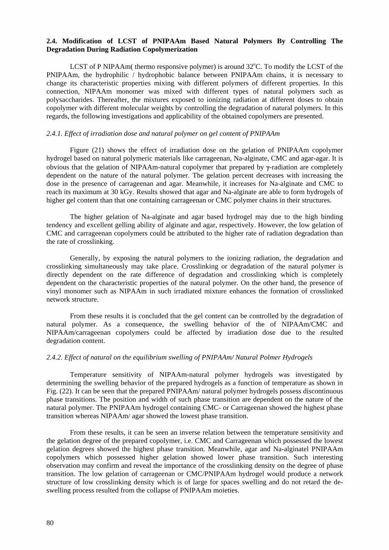
2.4. Modification of LCST of PNIPAAm Based Natural Polymers By Controlling The Degradation During Radiation Copolymerization
LCST of P NIPAAm( thermo responsive polymer) is around 32oC. To modify the LCST of the
PNIPAAm, the hydrophilic / hydrophobic balance between PNIPAAm chains, it is necessary to change its characteristic properties mixing with different polymers of different properties. In this connection, NIPAAm monomer was mixed with different types of natural polymers such as polysaccharides. Thereafter, the mixtures exposed to ionizing radiation at different doses to obtain copolymer with different molecular weights by controlling the degradation of natural polymers. In this regards, the following investigations and applicability of the obtained copolymers are presented.
2.4.1. Effect of irradiation dose and natural polymer on gel content of PNIPAAm
Figure (21) shows the effect of irradiation dose on the gelation of PNIPAAm copolymer hydrogel based on natural polymeric materials like carrageenan, Na-alginate, CMC and agar-agar. It is obvious that the gelation of NIPAAm-natural copolymer that prepared by γ-radiation are completely dependent on the nature of the natural polymer. The gelation percent decreases with increasing the dose in the presence of carrageenan and agar. Meanwhile, it increases for Na-alginate and CMC to reach its maximum at 30 kGy. Results showed that agar and Na-alginate are able to form hydrogels of higher gel content than that one containing carrageenan or CMC polymer chains in their structures.
The higher gelation of Na-alginate and agar based hydrogel may due to the high binding
tendency and excellent gelling ability of alginate and agar, respectively. However, the low gelation of CMC and carrageenan copolymers could be attributed to the higher rate of radiation degradation than the rate of crosslinking.
Generally, by exposing the natural polymers to the ionizing radiation, the degradation and
crosslinking simultaneously may take place. Crosslinking or degradation of the natural polymer is directly dependent on the rate difference of degradation and crosslinking which is completely dependent on the characteristic properties of the natural polymer. On the other hand, the presence of vinyl monomer such as NIPAAm in such irradiated mixture enhances the formation of crosslinked network structure.
From these results it is concluded that the gel content can be controlled by the degradation of
natural polymer. As a consequence, the swelling behavior of the of NIPAAm/CMC and NIPAAm/carrageenan copolymers could be affected by irradiation dose due to the resulted degradation content.
2.4.2. Effect of natural on the equilibrium swelling of PNIPAAm/ Natural Polmer Hydrogels
Temperature sensitivity of NIPAAm-natural polymer hydrogels was investigated by
determining the swelling behavior of the prepared hydrogels as a function of temperature as shown in Fig. (22). It can be seen that the prepared PNIPAAm/ natural polymer hydrogels possess discontinuous phase transitions. The position and width of such phase transition are dependent on the nature of the natural polymer. The PNIPAAm hydrogel containing CMC- or Carrageenan showed the highest phase transition whereas NIPAAm/ agar showed the lowest phase transition.
From these results, it can be seen an inverse relation between the temperature sensitivity and
the gelation degree of the prepared copolymer, i.e. CMC and Carrageenan which possessed the lowest gelation degrees showed the highest phase transition. Meanwhile, agar and Na-alginatel PNIPAAm copolymers which possessed higher gelation showed lower phase transition. Such interesting observation may confirm and reveal the importance of the crosslinking density on the degree of phase transition. The low gelation of carrageenan or CMC/PNIPAAm hydrogel would produce a network structure of low crosslinking density which is of large for spaces swelling and do not retard the de-swelling process resulted from the collapse of PNIPAAm moieties.
80
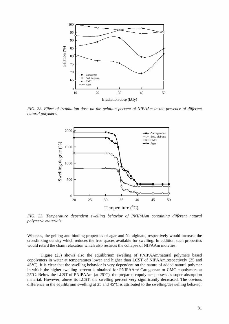
Irradiation dose (kGy)
10 20 30 40 50
Gel
atio
n (%
)
0
65
70
75
80
85
90
95
100
CarragenanSod. AlginateCMCAgar
FIG. 22. Effect of irradiation dose on the gelation percent of NIPAAm in the presence of different natural polymers.
Temperature (oC)
20 25 30 35 40 45 50
Swel
ling
degr
ee (%
)
0
500
1000
1500
2000CarrageenanSod. alginateCMCAgar
FIG. 23. Temperature dependent swelling behavior of PNIPAAm containing different natural polymeric materials.
Whereas, the gelling and binding properties of agar and Na-alginate, respectively would increase the crosslinking density which reduces the free spaces available for swelling. In addition such properties would retard the chain relaxation which also restricts the collapse of NIPAAm moieties.
Figure (23) shows also the equilibrium swelling of PNIPAAm/natural polymers based copolymers in water at temperatures lower and higher than LCST of NIPAAm,respectively (25 and 45°C). It is clear that the swelling behavior is very dependent on the nature of added natural polymer in which the higher swelling percent is obtained for PNIPAAm/ Carageenan or CMC copolymers at 25oC. Below the LCST of PNIPAAm (at 25oC), the prepared copolymer possess as super absorption material. However, above its LCST, the swelling percent very significantly decreased. The obvious difference in the equilibrium swelling at 25 and 45°C is attributed to the swelling/deswelling behavior
81
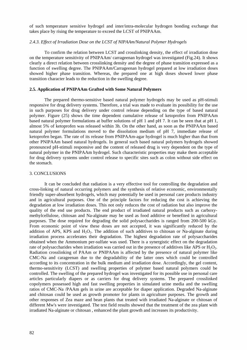
of such temperature sensitive hydrogel and inter/intra-molecular hydrogen bonding exchange that takes place by rising the temperature to exceed the LCST of PNIPAAm.
2.4.3. Effect of Irradiation Dose on the LCST of NIPAAm/Natural Polymer Hydrogels To confirm the relation between LCST and crosslinking density, the effect of irradiation dose on the temperature sensitivity of PNIPAAm/ carrageenan hydrogel was investigated (Fig.24). It shows clearly a direct relation between crosslinking density and the degree of phase transition expressed as a function of swelling degree. The PNIPAAm/Carrageenan hydrogel prepared at low irradiation doses showed higher phase transition. Whereas, the prepared one at high doses showed lower phase transition character leads to the reduction in the swelling degree.
2.5. Application of PNIPAAm Grafted with Some Natural Polymers
The prepared thermo-sensitive based natural polymer hydrogels may be used as pH-stimuli responsive for drug delivery systems. Therefore, a trial was made to evaluate its possibility for the use in such purposes for drug delivery under control release depending on the type of based natural polymer. Figure (25) shows the time dependent cumulative release of ketoprofen from PNIPAAm based natural polymer formulations at buffer solutions of pH 1 and pH 7. It can be seen that at pH 1, almost 5% of ketoprofen was released within 3h. On the other hand, as soon as the PNIPAAm based natural polymer formulations moved to the dissolution medium of pH 7, immediate release of ketoprofen began. The rate of its release from PNIPAAm-agar hydrogel is much higher than that from other PNIPAAm based natural hydrogels. In general such based natural polymers hydrogels showed pronounced pH-stimuli responsive and the content of released drug is very dependent on the type of natural polymer in the PNIPAAm hydrogel. Such characteristic properties may make them acceptable for drug delivery systems under control release to specific sites such as colon without side effect on the stomach.
3. CONCLUSIONS
It can be concluded that radiation is a very effective tool for controlling the degradation and cross-linking of natural occurring polymers and the synthesis of relative economic, environmentally friendly super-absorbent hydrogels, which may potentially be used in personal care products industry and in agricultural purposes. One of the principle factors for reducing the cost is achieving the degradation at low irradiation doses. This not only reduces the cost of radiation but also improve the quality of the end use products. The end product of irradiated natural products such as carboxy-methylcellulose, chitosan and Na-alginate may be used as food additive or benefited in agricultural purposes. The dose required for degrading the solid polysaccharides is ranged from 200-500 kGy. From economic point of view these doses are not accepted, it was significantly reduced by the addition of APS, KPS and H2O2. The addition of such additives to chitosan or Na-alginate during irradiation process accelerates their degradation. The highest degradation rate of polysaccharides obtained when the Ammonium per-sulfate was used. There is a synergistic effect on the degradation rate of polysaccharides when irradiation was carried out in the presence of additives like APS or H2O2. Radiation crosslinking of PAAm or PNIPAAm is affected by the presence of natural polymer like CMC-Na and carageenan due to the degradability of the latter ones which could be controlled according to its concentration in the bulk medium and irradiation dose. Accordingly, the gel content, thermo-sensitivity (LCST) and swelling properties of polymer based natural polymers could be controlled. The swelling of the prepared hydrogel was investigated for its possible use in personal care articles particularly diapers or as carriers for drug delivery systems. The prepared crosslinked copolymers possessed high and fast swelling properties in simulated urine media and the swelling ratios of CMC-Na /PAAm gels in urine are acceptable for diaper application. Degraded Na-alginate and chitosan could be used as growth promoter for plants in agriculture purposes. The growth and other responses of Zea maze and bean plants that treated with irradiated Na-alginate or chitosan of different Mw's were investigated. The test field results showed that the treatment of the zea plant with irradiated Na-alginate or chitosan , enhanced the plant growth and increases its productivity.
82

FIG. 24. The equilibrium swelling of PNIPAAm/ natural polymers 25 and 45°C.
Temperature (oC)
20 25 30 35 40 45 50
Swel
ling
degr
ee (%
)
0
500
1000
1500
2000
2500
3000
5321
Irradiation dose (M rad):
FIG. 25. Effect of temperature on the swelling percent for PNIPAAm/natural polymer hydrogels prepared at different irradiation doses.
FIG. 26. Effect of natural polymer on the release of ketoprofen from its corresponding copolymer with PNIPAAm at different interval times and pHs.
83
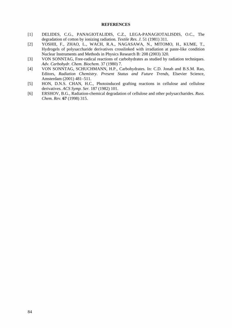
REFERENCES [1] DELIDES, C.G., PANAGIOTALIDIS, C.Z., LEGA-PANAGIOTALISDIS, O.C., The
degradation of cotton by ionizing radiation. Textile Res. J. 51 (1981) 311. [2] YOSHII, F., ZHAO, L., WACH, R.A., NAGASAWA, N., MITOMO, H., KUME, T.,
Hydrogels of polysaccharide derivatives crosslinked with irradiation at paste-like condition Nuclear Instruments and Methods in Physics Research B: 208 (2003) 320.
[3] VON SONNTAG, Free-radical reactions of carbohydrates as studied by radiation techniques. Adv. Carbohydr. Chem. Biochem. 37 (1980) 7.
[4] VON SONNTAG, SCHUCHMANN, H.P., Carbohydrates. In: C.D. Jonah and B.S.M. Rao, Editors, Radiation Chemistry. Present Status and Future Trends, Elsevier Science, Amsterdam (2001) 481–511.
[5] HON, D.N.S. CHAN, H.C., Photoinduced grafting reactions in cellulose and cellulose derivatives. ACS Symp. Ser. 187 (1982) 101.
[6] ERSHOV, B.G., Radiation-chemical degradation of cellulose and other polysaccharides. Russ. Chem. Rev. 67 (1998) 315.
84

EFFECT OF RADIATION ON ULTRA HIGH MOLECULAR WEIGHT POLYETHYLENE (UHMWPE)
SUNGSIK KIM, YOUNG CHANG NHO Radiation Application Div., Korea Atomic Energy Research Institute, Yusong, Daejon, Republic of Korea
Abstract
Ultra-high molecular weight polyethylene (UHMWPE) is routinely used for the manufacture of the acetabular cup for total hip replacements and the patellar components for total knee replacements. However, occasional failures, within 6 – 8 years of implantation in the case of active or heavy patients, have been reported. Most failures are attributed to the oxidative degradation of the PE molecules initiated by the reaction of free radicals, generated by irradiation, with oxygen during shelf storage and implantation. Irradiation is usually employed for sterilizing and the crosslinking UHMWPE. Polymeric material with irradiation may undergo an increase in their molecular weight due to crossing and/or a decrease in their molecular weight due to chain scission simultaneously. Also the free radicals are formed in UHMWPE during this process in addition to crosslinking. These polymer radicals transform into oxidized moieties if oxygen is present in the vicinity of formed radicals or remain trapped in the polymer matrix for a certain period of time after irradiation. These trapped radicals may further undergo some reactions during shelf storage and implantation after irradiation for a long time period, resulting in significant alteration of the physical properties of irradiation UHMWPE, if a large amount of polymer radicals remain trapped after irradiation. An electron spin resonance spectroscopic study was undertaken to investigate the remaining free radicals in UHMWPE after electron beam (EB) irradiation up to 500 kGy in air and N2 environment. Heat treatment was employed at 110oC and 145oC for varying periods of time to scavenge the free radicals. The free radicals were rapidly decayed for one hour and gradually decayed as a function of time by the heat treatment. The scavenging of the free radicals was done more rapidly at a 145oC heat treatment than 110oC. Therefore a longer heat treatment time is required to scavenge all the free radicals formed in UHMWPE at 110oC. The oxidation profiles showed that the oxidation index (OI) of the heat-treated UHMWPE was lower than the OI of non heat-treated UHMWPE. The heat treatment of irradiated UHMWPE can substantially reduce the concentration of the free radicals; thereby the UHMWPE has resistance against long-term oxidative degradation.
1. INTRODUCTION
Ultra-high molecular weight polyethylene (UHMWPE) has been successfully used as bearing parts in orthopedic implants for nearly four decades. Irradiation is usually employed for sterilizing and the crosslinking method of UHMWPE. Polymeric material with irradiation may undergo an increase in their molecular weight due to crossing and/or a decrease in their molecular weight due to chain scission simultaneously. Also the free radicals are formed in UHMWPE during this process in addition to crosslinking. These polymer radicals transform into oxidized moieties if oxygen is present in the vicinity of formed radicals or remain trapped in the polymer matrix for a certain period of time after irradiation. The formed free radicals cause oxidative degradation of the PE molecules by a reaction with oxygen during shelf storage and implantation during a long time period. This oxidative degradation changes the physical properties of the UHMWPE and probably can cause an implantation failure. In this study, we investigated the UHMWPE radicals remaining after irradiation as a function of dose and examined how effective the heat treatment of the irradiated UHMWPE was for scavenging the free radicals by the changes of the electron spin resonance (ERS) spectra. The degree of crosslinking was estimated via the determination of the gel fraction. Also the Fourier Transform Infrared and the differential scanning calorimetry were employed to study the changes of the chemical and physical properties. The heat treatment took place either above or below the melt transition. Heat treatment below the melt transition is referred to as annealing and above the melt transition is referred to as remelting. The oxidation profiles were measured by Fourier Transform Infrared Spectroscopy.
85

2. MATERIALS AND METHODS
2.1. Heat treatment after electron beam irradiation
The samples in this experiment were prepared from a 10 mm diameter ram extruded UHMWPE cylindrical bar stock (GUR 4150, average molecular weight of approximately 9.3 million and density of 0.93 g/ml). EB irradiation was carried out at a dose rate of 7500 kGy/h using an ELV-4 accelerator (energy: 1 MeV, current: 2.5 mA) in air and N2 environment. The specimens that had been irradiated were heated in a nitrogen environment at a heat rate 2°C/min and remained at 110°C and 145°C for 7 hours and 2 hours respectively. The specimens were slowly cooled at a cooling rate 1°C/min to room temperature.
2.2. Fourier transform infrared spectroscopy
FTIR specimens were microtomed into 200μm thick slices from the surface of the specimen as shown in Fig. 1. The oxidation profiles were obtained from a FT-IR (Tensor 37, Bruker) using 32 scans at a resolution 4 cm-1. The oxidation index was calculated by the ratio of the peak area of the ketone (C=O) group absorption band at 1717 cm-1 to the area of the methylene group reference band at 1370 cm-1.
1
1
1370
1717
−
−=
cmat
cmat
AreaAbsorbtionAreaAbsorbtion
IndexOxidation
The trans-vinylene (-C=C-) index also was calculated by the ratio of the peak area of the trans-vinylene band at 965 cm-1 to the area of the methylene group reference band at 1370 cm-1.
1
1
1370
965
−
−=−
cmat
cmat
AreaAbsorbtionAreaAbsorbtion
IndexvinyleneTrans
2.3. Electron spin resonance
The specimens for the free radical measurements were machined (3×5×1.5 mm3) after cutting off 0.8 mm from the surface of the UHMWPE bar stock as shown in Fig. 1. An X-band ESR spectrometer (EPR EMX, Bruker), operating at 9.648 GHz microwave and 100 kHz magnetic field modulation frequencies, was used. While the microwave power was maintained 20.12 mW, the modulation amplitude was 1 G and 5 G. The double integration method was used to determine the relative free radical concentration.
2.4. Gel fraction (%)
The gel fraction of each sample was analyzed as a function of dose. All specimens were collected after cutting off 0.2 mm from the surface of the irradiated UHMWPE. Extraction of the sol-fraction was performed by boiling in xylene for 48 hours, with 0.5 wt% of antioxidant (2, 6-di-t-butyl-4-methyl phenol) added to prevent oxidation. After extraction, specimens were dried at 80°C in vacuum oven to a constant weight. The gel fraction was determined from the ratio of the weight of the dried extracted specimen to the initial weight of the dry non extracted specimens.
100(%) ×=i
d
WWfractionGel
86
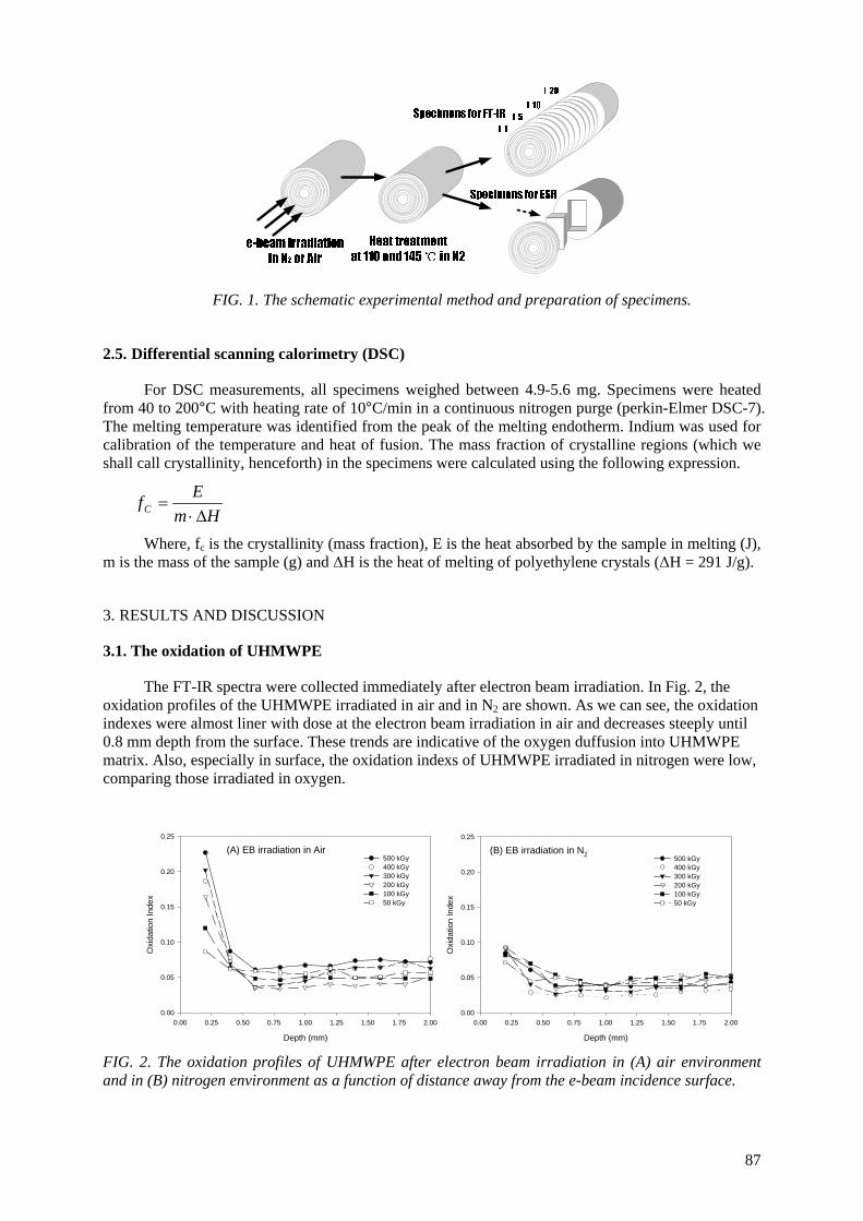
FIG. 1. The schematic experimental method and preparation of specimens.
2.5. Differential scanning calorimetry (DSC)
For DSC measurements, all specimens weighed between 4.9-5.6 mg. Specimens were heated from 40 to 200°C with heating rate of 10°C/min in a continuous nitrogen purge (perkin-Elmer DSC-7). The melting temperature was identified from the peak of the melting endotherm. Indium was used for calibration of the temperature and heat of fusion. The mass fraction of crystalline regions (which we shall call crystallinity, henceforth) in the specimens were calculated using the following expression.
HmEfC Δ⋅
=
Where, fc is the crystallinity (mass fraction), E is the heat absorbed by the sample in melting (J), m is the mass of the sample (g) and ΔH is the heat of melting of polyethylene crystals (ΔH = 291 J/g).
3. RESULTS AND DISCUSSION
3.1. The oxidation of UHMWPE
The FT-IR spectra were collected immediately after electron beam irradiation. In Fig. 2, the oxidation profiles of the UHMWPE irradiated in air and in N2 are shown. As we can see, the oxidation indexes were almost liner with dose at the electron beam irradiation in air and decreases steeply until 0.8 mm depth from the surface. These trends are indicative of the oxygen duffusion into UHMWPE matrix. Also, especially in surface, the oxidation indexs of UHMWPE irradiated in nitrogen were low, comparing those irradiated in oxygen.
(A) EB irradiation in Air
Depth (mm)
0.00 0.25 0.50 0.75 1.00 1.25 1.50 1.75 2.00
Oxi
datio
n In
dex
0.00
0.05
0.10
0.15
0.20
0.25
500 kGy400 kGy 300 kGy200 kGy100 kGy50 kGy
(B) EB irradiation in N2
Depth (mm)
0.00 0.25 0.50 0.75 1.00 1.25 1.50 1.75 2.00
Oxi
datio
n In
dex
0.00
0.05
0.10
0.15
0.20
0.25
500 kGy400 kGy300 kGy200 kGy100 kGy50 kGy
FIG. 2. The oxidation profiles of UHMWPE after electron beam irradiation in (A) air environment and in (B) nitrogen environment as a function of distance away from the e-beam incidence surface.
87
The penetration of radiation with electron beam depends on the energy of the electrons used and the density of absorbing material. The penetration of the EB radiation and the distance of the peak dose depend on the energy of the electrons used and the density of the absorbing material. For instance, with UHMWPE (density of around 0.93 g/cm3), the dose penetration of a 1 MeV electron beam is about 3.58 mm and the distance of the peak dose occurs at about 1.7 mm from the surface, theoretically.
When the absorbing material is polyethylene, chemical change induced by the radiolytic reactions can be used to determine the absorbed radiation dose level. One of the radiolytic events that occur during the irradiation of polyethylene is the formation of the trans-vinylene unsaturations. Fig. 3 shows the variation in the trans-vinylene index yield as a function of depth away from the electron beam incidence surface. The trans-vinylene index remained constant for about 2 mm below the electron beam incidence surface. Beyond depths of 2 mm, the trans-vinylene index decreased rapidly.
(A) Irradiation in Air
Depth(mm)0.0 0.5 1.0 1.5 2.0 2.5 3.0 3.5 4.0 4.5
Tran
s vi
nyle
ne In
dex
0.00
0.05
0.10
0.15
0.20
500 kGy400 kGy300 kGy200 kGy100 kGy50 kGy
(B) Irradiation in N2
Depth(mm)0.0 0.5 1.0 1.5 2.0 2.5 3.0 3.5 4.0 4.5
Tran
s vi
nyle
ne In
dex
0.00
0.05
0.10
0.15
0.20
500 kGy400 kGy300 kGy200 kGy 100 kGy50 kGy
FIG. 3. The trans-vinylene index profiles of the UHMWPE after electron beam irradiation (A) in air and (B) in nitrogen as a function of depth from the electron beam incidence surface.
In Fig. 4(A) and 4(B), the oxidation profiles of the UHMWPE irradiated in air and in N2 without
heat treatment for dose are compared at an actual 45 days shelf aging time (1 atm air at 25oC). There is no significant difference of the oxidation index (OI) beyond the 4 mm depth from the UHMWPE surface as a function of dose. However, the maximum OI occurred at the surface of the UHMWPE irradiated in air. The second maximum OI occurred at about a 2.2 mm depth and this OI increased with an increasing of irradiation dose. The minimum oxidation index appears at about 0.8 mm from the surface below 4 mm depth. Although the main effect of oxidation of UHMWPE is oxygen diffusion below about 0.8 mm depth, the main effect of oxidation is the free radicals concentration beyond the 0.8 mm depth.
Fig. 4(C) and 3(D) show the oxidation profiles of the heat-treated UHMWPE after irradiation in N2 at 110oC and 145oC at an actual 45 days shelf aging time. As seen, the OI of the heat-treated UHMWPE was lower than the non heat-treated UHMWPE.
The free radical concentration gradually increases with an increasing dose and these free radicals cause the oxidative degradation of the UHMWPE. At the same irradiation dose, the oxidation index is higher in the peak dose region (more accurately, the theoretical peak dose : 1.7 mm depth). As shown in the oxidation profiles, the free radicals scavenging by heat treatment can inhibit the oxidative degradation of the UHMWPE irradiated during a long period of time.
88
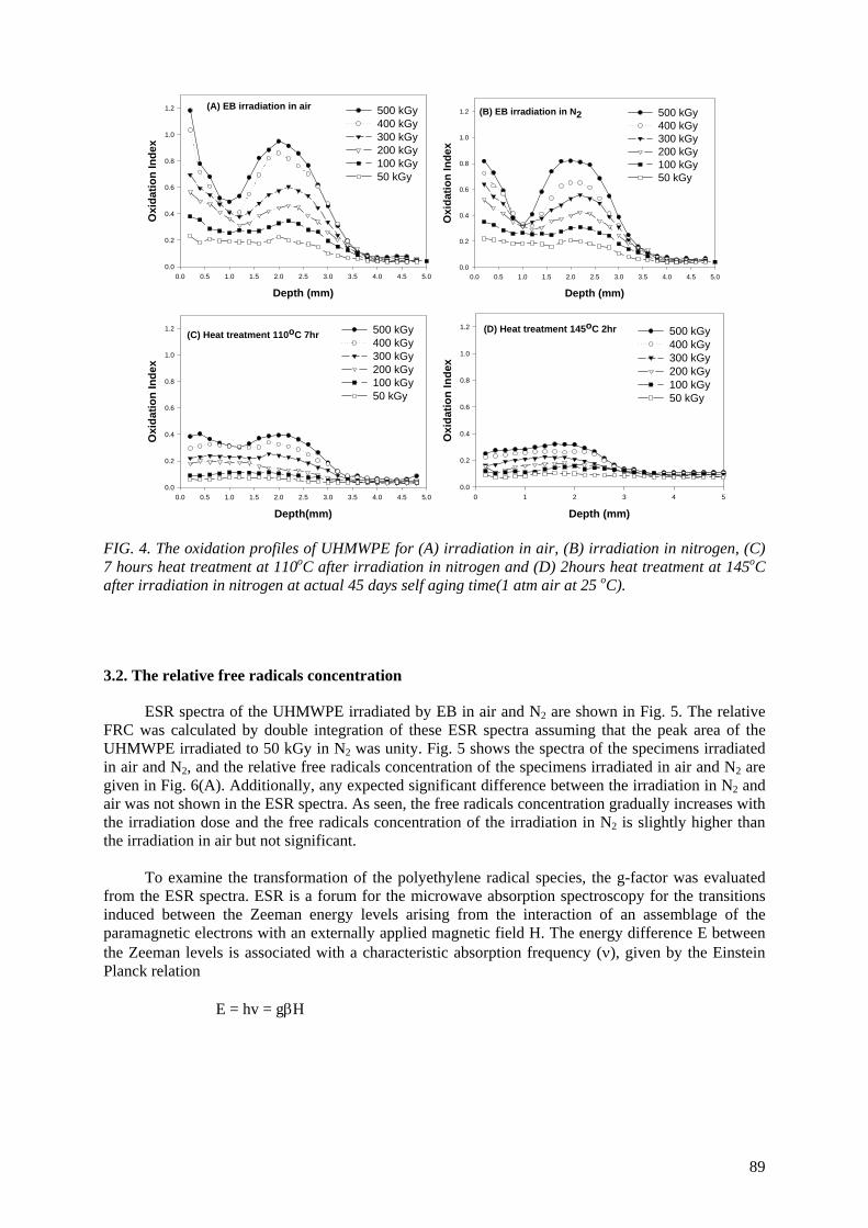
Depth (mm)0.0 0.5 1.0 1.5 2.0 2.5 3.0 3.5 4.0 4.5 5.0
Oxi
datio
n In
dex
0.0
0.2
0.4
0.6
0.8
1.0
1.2 500 kGy400 kGy300 kGy200 kGy100 kGy50 kGy
(A) EB irradiation in air
Depth (mm)0.0 0.5 1.0 1.5 2.0 2.5 3.0 3.5 4.0 4.5 5.0
Oxi
datio
n In
dex
0.0
0.2
0.4
0.6
0.8
1.0
1.2 500 kGy400 kGy300 kGy200 kGy100 kGy50 kGy
(B) EB irradiation in N2
Depth(mm)0.0 0.5 1.0 1.5 2.0 2.5 3.0 3.5 4.0 4.5 5.0
Oxi
datio
n In
dex
0.0
0.2
0.4
0.6
0.8
1.0
1.2 500 kGy400 kGy300 kGy200 kGy100 kGy50 kGy
(C) Heat treatment 110oC 7hr
Depth (mm)0 1 2 3 4 5
Oxi
datio
n In
dex
0.0
0.2
0.4
0.6
0.8
1.0
1.2 500 kGy400 kGy300 kGy200 kGy100 kGy50 kGy
(D) Heat treatment 145oC 2hr
FIG. 4. The oxidation profiles of UHMWPE for (A) irradiation in air, (B) irradiation in nitrogen, (C) 7 hours heat treatment at 110oC after irradiation in nitrogen and (D) 2hours heat treatment at 145oC after irradiation in nitrogen at actual 45 days self aging time(1 atm air at 25 oC).
3.2. The relative free radicals concentration
ESR spectra of the UHMWPE irradiated by EB in air and N2 are shown in Fig. 5. The relative FRC was calculated by double integration of these ESR spectra assuming that the peak area of the UHMWPE irradiated to 50 kGy in N2 was unity. Fig. 5 shows the spectra of the specimens irradiated in air and N2, and the relative free radicals concentration of the specimens irradiated in air and N2 are given in Fig. 6(A). Additionally, any expected significant difference between the irradiation in N2 and air was not shown in the ESR spectra. As seen, the free radicals concentration gradually increases with the irradiation dose and the free radicals concentration of the irradiation in N2 is slightly higher than the irradiation in air but not significant.
To examine the transformation of the polyethylene radical species, the g-factor was evaluated
from the ESR spectra. ESR is a forum for the microwave absorption spectroscopy for the transitions induced between the Zeeman energy levels arising from the interaction of an assemblage of the paramagnetic electrons with an externally applied magnetic field H. The energy difference E between the Zeeman levels is associated with a characteristic absorption frequency (ν), given by the Einstein Planck relation
E = hv = gβH
89

(A) Irradiation in air
Gauss field (G)
3360 3380 3400 3420 3440 3460 3480 3500 3520
50 kGy
100 kGy
300 kGy
500 kGy
Gauss field (G)
3360 3380 3400 3420 3440 3460 3480 3500 3520
50 kGy
100 kGy
300 kGy
500 kGy
(B) Irradiation in N2
FIG. 5. The change of ESR spectra of UHMWPE irradiated in (A) air and (B) nitrogen.
Where h is Planck’s constant and β the Bohr magneton. Spectroscopic splitting factor g is defined by hv=gβH. The position center of the spectrum gives the magnetic field H at which the resonance occurs and can be used to calculate the g value. A free electron spin is expected to have a value of g = 2.0. In real materials, the g may differ from this value, depending on the variations in the coupling between the spin and orbital angular momentum. The g values of some organic radicals are as follows:
The changes of g-factor of UHMWPE irradiated in air and N2 are shown in Fig. 6(B). It is accepted that irradiation of UHMWPE produces alkyl radicals (-•CH-CH2-), which gradually transform to more stable ally radicals (-•CH-CH=CH-) with an increase of dose. But g-factor of UHMWPE irradiated in air increase for higher dose because of the oxygen diffusion into UHMWPE matrix.
Dose (kGy)0 100 200 300 400 500
Rel
ativ
e FR
C
0.0
0.5
1.0
1.5
2.0
2.5
3.0
EB irradiation in N2 EB irradiation in Air
(A)
Dose (kGy)0 100 200 300 400 500
g-fa
ctor
2.0026
2.0028
2.0030
2.0032
2.0034
2.0036
2.0038
2.0040
EB irradiation in N2 EB irradiation in Air
(B)
FIG. 6. The change of (A) relative free radical concentration and (B) g-factor of irradiated in air and nitrogen.
90
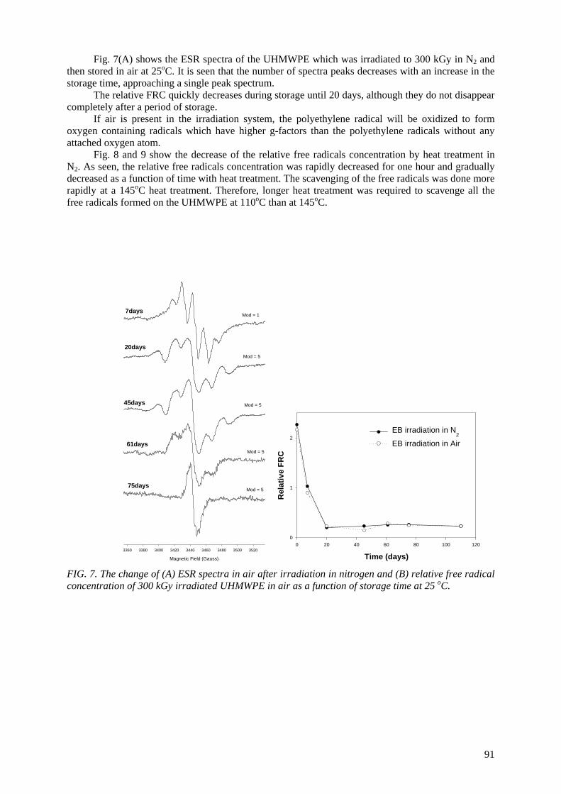
Fig. 7(A) shows the ESR spectra of the UHMWPE which was irradiated to 300 kGy in N2 and then stored in air at 25oC. It is seen that the number of spectra peaks decreases with an increase in the storage time, approaching a single peak spectrum.
The relative FRC quickly decreases during storage until 20 days, although they do not disappear completely after a period of storage.
If air is present in the irradiation system, the polyethylene radical will be oxidized to form oxygen containing radicals which have higher g-factors than the polyethylene radicals without any attached oxygen atom.
Fig. 8 and 9 show the decrease of the relative free radicals concentration by heat treatment in N2. As seen, the relative free radicals concentration was rapidly decreased for one hour and gradually decreased as a function of time with heat treatment. The scavenging of the free radicals was done more rapidly at a 145oC heat treatment. Therefore, longer heat treatment was required to scavenge all the free radicals formed on the UHMWPE at 110oC than at 145oC.
Magnetic Field (Gauss)
3360 3380 3400 3420 3440 3460 3480 3500 3520
7days
20days
45days
61days
75days
Mod = 1
Mod = 5
Mod = 5
Mod = 5
Mod = 5
Time (days)0 20 40 60 80 100 120
Rel
ativ
e FR
C
0
1
2EB irradiation in N
2
EB irradiation in Air
FIG. 7. The change of (A) ESR spectra in air after irradiation in nitrogen and (B) relative free radical concentration of 300 kGy irradiated UHMWPE in air as a function of storage time at 25 oC.
91
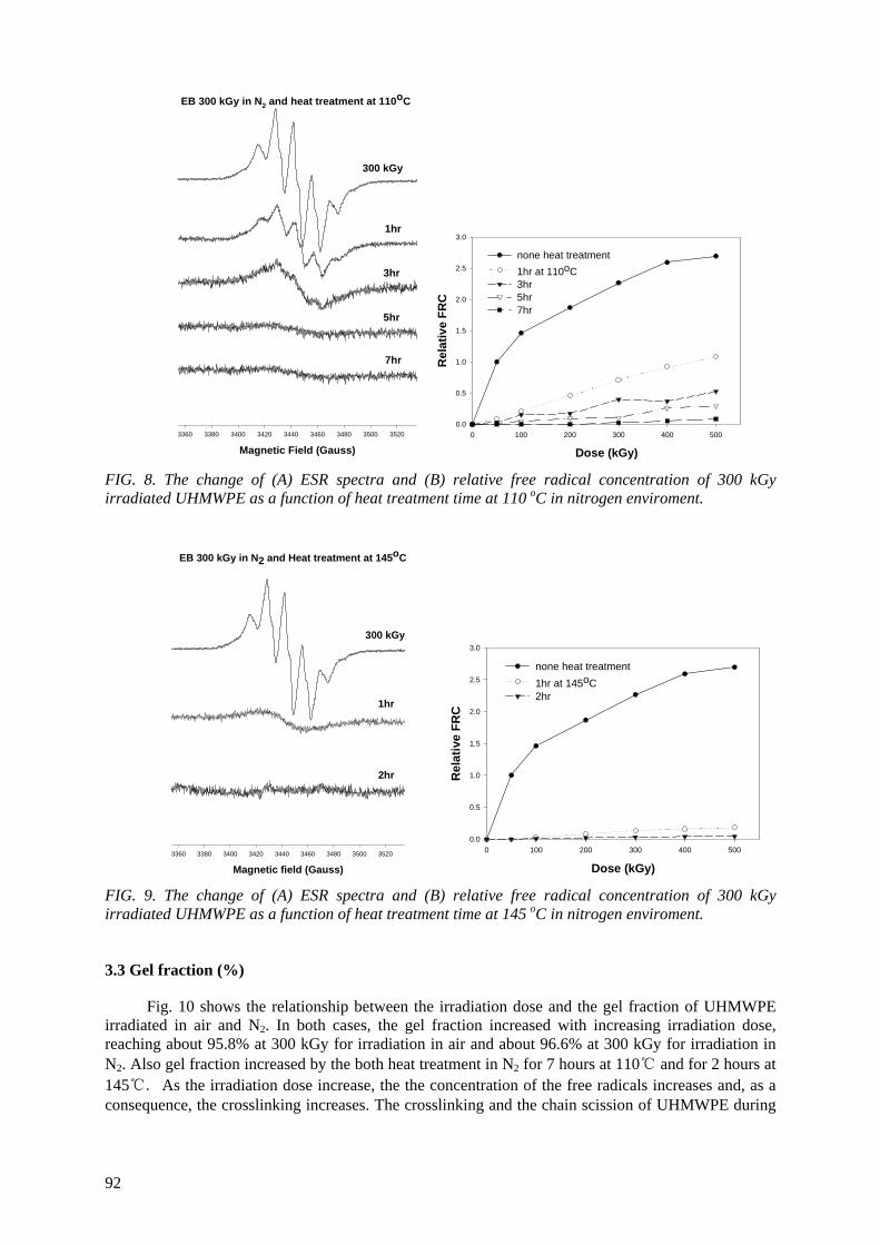
Magnetic Field (Gauss)3360 3380 3400 3420 3440 3460 3480 3500 3520
300 kGy
1hr
3hr
5hr
EB 300 kGy in N2 and heat treatment at 110oC
7hr
Dose (kGy)0 100 200 300 400 500
Rel
ativ
e FR
C0.0
0.5
1.0
1.5
2.0
2.5
3.0
none heat treatment 1hr at 110oC 3hr 5hr 7hr
FIG. 8. The change of (A) ESR spectra and (B) relative free radical concentration of 300 kGy irradiated UHMWPE as a function of heat treatment time at 110 oC in nitrogen enviroment.
Magnetic field (Gauss)3360 3380 3400 3420 3440 3460 3480 3500 3520
1hr
2hr
EB 300 kGy in N2 and Heat treatment at 145oC
300 kGy
Dose (kGy)0 100 200 300 400 500
Rel
ativ
e FR
C
0.0
0.5
1.0
1.5
2.0
2.5
3.0
none heat treatment 1hr at 145oC2hr
FIG. 9. The change of (A) ESR spectra and (B) relative free radical concentration of 300 kGy irradiated UHMWPE as a function of heat treatment time at 145 oC in nitrogen enviroment.
3.3 Gel fraction (%)
Fig. 10 shows the relationship between the irradiation dose and the gel fraction of UHMWPE irradiated in air and N2. In both cases, the gel fraction increased with increasing irradiation dose, reaching about 95.8% at 300 kGy for irradiation in air and about 96.6% at 300 kGy for irradiation in N2. Also gel fraction increased by the both heat treatment in N2 for 7 hours at 110℃ and for 2 hours at 145℃. As the irradiation dose increase, the the concentration of the free radicals increases and, as a consequence, the crosslinking increases. The crosslinking and the chain scission of UHMWPE during
92
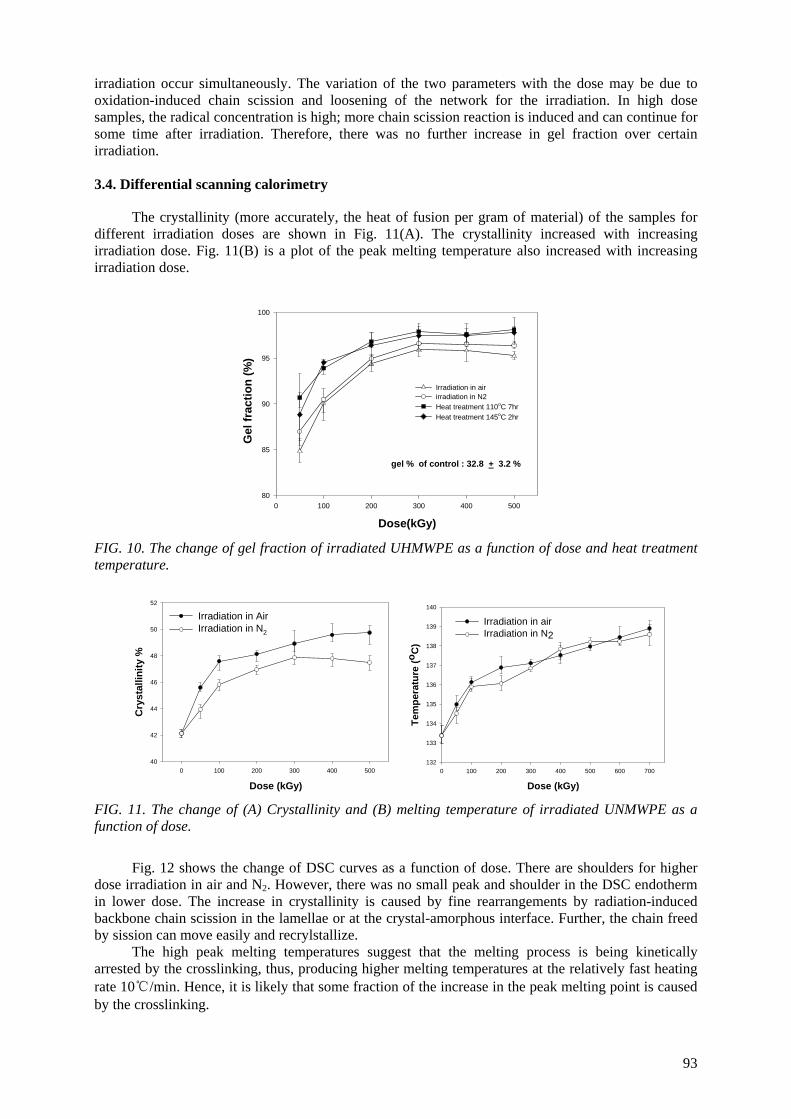
irradiation occur simultaneously. The variation of the two parameters with the dose may be due to oxidation-induced chain scission and loosening of the network for the irradiation. In high dose samples, the radical concentration is high; more chain scission reaction is induced and can continue for some time after irradiation. Therefore, there was no further increase in gel fraction over certain irradiation.
3.4. Differential scanning calorimetry
The crystallinity (more accurately, the heat of fusion per gram of material) of the samples for different irradiation doses are shown in Fig. 11(A). The crystallinity increased with increasing irradiation dose. Fig. 11(B) is a plot of the peak melting temperature also increased with increasing irradiation dose.
Dose(kGy)0 100 200 300 400 500
Gel
frac
tion
(%)
80
85
90
95
100
Irradiation in airirradiation in N2Heat treatment 110oC 7hrHeat treatment 145oC 2hr
gel % of control : 32.8 + 3.2 %
FIG. 10. The change of gel fraction of irradiated UHMWPE as a function of dose and heat treatment temperature.
Dose (kGy)0 100 200 300 400 500
Cry
stal
linity
%
40
42
44
46
48
50
52
Irradiation in AirIrradiation in N2
Dose (kGy)0 100 200 300 400 500 600 700
Tem
pera
ture
(oC
)
132
133
134
135
136
137
138
139
140
Irradiation in airIrradiation in N2
FIG. 11. The change of (A) Crystallinity and (B) melting temperature of irradiated UNMWPE as a function of dose.
Fig. 12 shows the change of DSC curves as a function of dose. There are shoulders for higher dose irradiation in air and N2. However, there was no small peak and shoulder in the DSC endotherm in lower dose. The increase in crystallinity is caused by fine rearrangements by radiation-induced backbone chain scission in the lamellae or at the crystal-amorphous interface. Further, the chain freed by sission can move easily and recrylstallize.
The high peak melting temperatures suggest that the melting process is being kinetically arrested by the crosslinking, thus, producing higher melting temperatures at the relatively fast heating rate 10℃/min. Hence, it is likely that some fraction of the increase in the peak melting point is caused by the crosslinking.
93
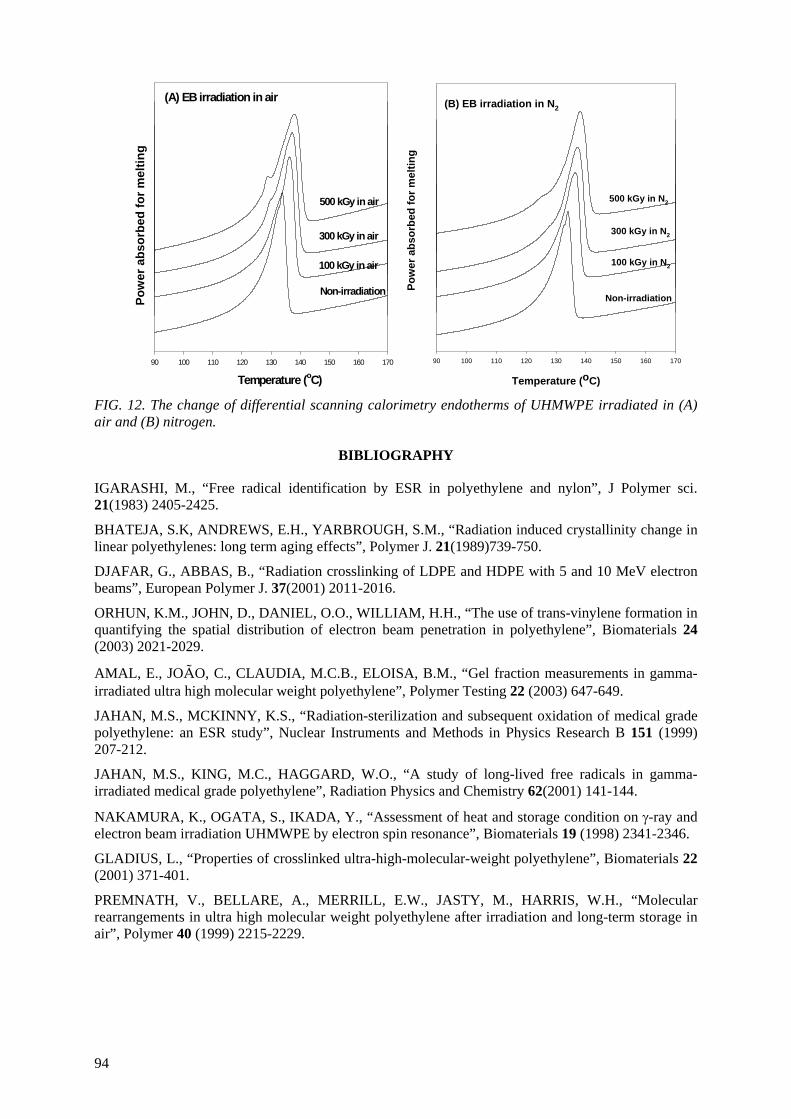
Temperature (oC)90 100 110 120 130 140 150 160 170
Pow
er a
bsor
bed
for m
eltin
g
Non-irradiation
100 kGy in air
300 kGy in air
500 kGy in air
(A) EB irradiation in air
Temperature (oC)
90 100 110 120 130 140 150 160 170
Pow
er a
bsor
bed
for m
eltin
g
500 kGy in N2
Non-irradiation
300 kGy in N2
100 kGy in N2
(B) EB irradiation in N2
FIG. 12. The change of differential scanning calorimetry endotherms of UHMWPE irradiated in (A) air and (B) nitrogen.
BIBLIOGRAPHY
IGARASHI, M., “Free radical identification by ESR in polyethylene and nylon”, J Polymer sci. 21(1983) 2405-2425.
BHATEJA, S.K, ANDREWS, E.H., YARBROUGH, S.M., “Radiation induced crystallinity change in linear polyethylenes: long term aging effects”, Polymer J. 21(1989)739-750.
DJAFAR, G., ABBAS, B., “Radiation crosslinking of LDPE and HDPE with 5 and 10 MeV electron beams”, European Polymer J. 37(2001) 2011-2016.
ORHUN, K.M., JOHN, D., DANIEL, O.O., WILLIAM, H.H., “The use of trans-vinylene formation in quantifying the spatial distribution of electron beam penetration in polyethylene”, Biomaterials 24 (2003) 2021-2029.
AMAL, E., JOÃO, C., CLAUDIA, M.C.B., ELOISA, B.M., “Gel fraction measurements in gamma-irradiated ultra high molecular weight polyethylene”, Polymer Testing 22 (2003) 647-649.
JAHAN, M.S., MCKINNY, K.S., “Radiation-sterilization and subsequent oxidation of medical grade polyethylene: an ESR study”, Nuclear Instruments and Methods in Physics Research B 151 (1999) 207-212.
JAHAN, M.S., KING, M.C., HAGGARD, W.O., “A study of long-lived free radicals in gamma-irradiated medical grade polyethylene”, Radiation Physics and Chemistry 62(2001) 141-144.
NAKAMURA, K., OGATA, S., IKADA, Y., “Assessment of heat and storage condition on γ-ray and electron beam irradiation UHMWPE by electron spin resonance”, Biomaterials 19 (1998) 2341-2346.
GLADIUS, L., “Properties of crosslinked ultra-high-molecular-weight polyethylene”, Biomaterials 22 (2001) 371-401.
PREMNATH, V., BELLARE, A., MERRILL, E.W., JASTY, M., HARRIS, W.H., “Molecular rearrangements in ultra high molecular weight polyethylene after irradiation and long-term storage in air”, Polymer 40 (1999) 2215-2229.
94
MODIFICATION OF MICROSTRUCTURES AND PHYSICAL PROPERTIES OF ULTRA HIGH MOLECULAR WEIGHT POLYETHYLENE BY ELECTRON BEAM IRRADIATION
Y.C. NHO Radiation Application Div. Korea Atomic Energy Research Institute, Daejeon, Republic of Korea S.M. LEE, H.H. SONG Department of Polymer Science and Engineering, Hannam University, Daejeon, Repubic of Korea
Abstract An ultra high molecular weight polyethylene was irradiated with the electron beam at dose levels ranging from 100 kGy to 1MGy. The microstructures of the irradiated samples were characterized by FTIR, gel fraction measurement, DSC and small and wide angle X ray scattering. For the mechanical properties, a static tensile test and creep experiment were also performed. The cross-linking and the crystal morphology changes were the main microstructural changes to influence the mechanical properties. It was found that 250 kGy appeared to the optimal dose level to induce cross-links in the amorphous area and recrystalliztion in the crystal lamellae. At doses above 250 kGy, the electron beam penetrates into the crystal domains, resulting in cross-links in the crystal domains and reduction in the crystal size and crystallinity. The static mechanical properties (modulus, strength) and the creep resistance were enhanced by the electron beam irradiation. The stiffness rather correlated with the degree of cross-links, while the strength with the crystal morphology. 1. INTRODUCTION
Ultra high molecular weight polyethylene (UHMWPE) is named from the unusually high molecular weight (higher than 3 × 10⁶ g/mol) which is about 10-20 times longer than the ordinary linear high density polyethylene. Because the ultra high molecular weight polymer exhibits superior wear and fatigue properties as well as biocompatibility, it has been utilized for the replacement of damaged or diseased articulating cartilage in joint replacement surgery.[1-4] However, one of the major problem for UHMWPE utilizing as the biomaterials is the long term wear or fatigue of the polymer to produce debris particles or shape deformation which cause loosening the joint prostheses and foreign body reaction problem.[1,4,5] Several studies to improve the wear resistance have been attempted.[6-8] Oonish et al.[6] have revealed for the first time that the UHMWPE irradiated with γ rays had shown high wear resistance. The radiation technique of γ ray has been the most popular technique to achieve both sterilization and improving mechanical properties as required for the biomaterials. Recent advances in electron beam technology, however, have made the electron beam irradiation technique as a strong competitor to the γ-radiation process.[10] Although the interactions with the polymeric material are basically the same for γ-radiation and high energy electron beam, some differences between the two techniques are observed in their outcome.[11,12]
It is well known that the high density cross-linking is induced by the high energy radiation, which is
considered as one of the major factors to improve mechanical properties of irradiated polymers.[1,14] The cross-linking reaction is effected by the irradiation environment and the initial polymer morphology such as degree of crystallinity, crystal size distribution, molecular weight, so on.[10,15-19] It is then highly expected that fine structural changes (other than the cross-linking) are induced during the irradiation process and they must play an important role in modifying the physical properties. Nevertheless, systematic studies on the microstructures and their changes by the irradiation and their correlations with the physical properties are very rare.
The objective of this work is to elucidate the microstructural modifications and related physical property changes of the UHMWPE by the electron beam irradiation with doses ranging from 100 kGy to 1MGy. We employed the small and wide angle X ray scattering, FTIR, and DSC for the detailed structural investigation and examined the structure-property correlations of irradiated UHMWPE.
95
2. EXPERIMENTAL 2.1. Materials and sample preparation
An ultra high molecular weight polyethylene (UHMWPE) was received as a compression molded sheet of 1.2 cm thickness. The molecular weight is about 4.5x10⁶ g/mol. For the tensile test the sample was initially milled into a rectangular sheet of 5 mm thickness and was compression molded at 190 oC in a home made mold designed after the ASTM D68 standard. Sufficient time was allowed before releasing the pressure in order not to induce any orientation in the sample during the compression molding.
2.2. Electron beam irradiation
Electron beam irradiation was carried out in air utilizing the accelerator (ELV-4) at EB-tech, Daejeon, S. Korea. The electron energy operated was 1 Mev. The heat generated during the irradiation was cooled using an aluminum cold plate in order to prevent any thermal effect on the samples during the irradiation. The irradiation doses were chosen at 100, 250, 500, 750, 1000 kGy and conveyer speed was 1m/min (100 kGy) and 2m/min (250 kGy~1MGy).
2.3. Characterization
Thermal properties of the electron beam irradiated samples were studied using a differential scanning calorimeter (TA DSC2910). Samples of ~4 mg were measured in a nitrogen gas atmosphere and the heating rate was at 10 oC/min. The percent crystallinity of the samples were derived based on the heat of fusion measurement,
(%)100×Δ
Δ=
PE
samplec H
Hx (1)
where ΔHsample represents the heat of fusion of irradiated sample and ΔHPE for the heat of fusion of 100% crystallinity.[20]
Two main reactions associated with the high energy irradiation are the chain scission and cross-
linking reaction[4,21]. To examine the two reactions, FTIR spectroscopy experiments were performed utilizing a Perkin-Elmer 1000PC spectrometer. For the efficient measurements, the irradiated samples were microtomed into a 25 μm thickness.
Gel content and swelling ratio were determined based on the ASTM D2765-95 method. However, the specimen size (5mm × 5mm × 2.5mm, 49±1 g ) was chosen somewhat larger than suggested for the accuracy of the data. The samples in a 25 μm metal mesh were kept in xylene at 120 oC for 48 h. The weight was measured (Wg) after the solvent on the specimen surface being evaporated. The specimen, then, was dried in a vacuum oven at 120 oC for 72 h and the weight (Wd) was measured. The percent extract and swelling ratio are derived as follows:
extract % = [(W0 − Wd)/W0] 100 (2) swelling ratio = [(Wg − Wd)/Wd] K + 1 (3)
Where W0 is the original weight of specimen tested, Wd the weight of dried gel, Wg the weight of swollen gel after immersion period, K the density of solvent at the immersion temperature (approx. 1.08). [21,22] Low percent extract represents the high gel fraction and low swelling ratio the high cross-linking density.
Wide and small angle X ray scattering were performed at the 4C1 and 4C2 X ray beamlines in Pohang Accelerator Laboratory. X ray beam from the synchrotron radiation was utilized. The X ray wave length was 1.608 A and the beam size at the sample position was 0.4 × 0.4 mm. Two dimensional position
96
sensitive area detector was utilized to collect the scattered data. The sample to detector distance was 9.03 cm for the wide angle X ray scattering and 310 cm for the small angle X ray scattering.
For the mechanical properties, both static tensile test and creep test were performed. The tensile properties were measured using a tensile tester (Shimadzu AG-5000G). The specimen size was 5.3 × 2.5 × 54 mm and test was made at the speed of 3mm/min in the atmosphere. A laboratory built creep tester was utilized for the creep test. The load was controlled by using the high pressure N2 gas and a digitial pressure gage. A 4-step load method was utilized to achieve a long term creep behavior with the short term experimental data. The applied loads were 2.94, 4.90, 6.86, 8.82 MPa and each step load was applied when the creep deformation reaches a plateau. The entire time span for the creep test of each sample was for about 80 h.
2. 4. X ray data analysis
The collected X ray scattered intensities at wide angles and those of small angles contain structural information of different length scale in real space. The analysis of the wide angle X ray intensities is rather straight forward. The raw intensity curves were analyzed using a conventional ‘Curve Fit’ program to decompose the individual peaks from the intensity curves. The crystallinity index ( ) and crystal thicknesses (t) were then estimated by the following equations;
cx
t
cc I
Ix = (4)
where Ic is the integrated intensities of crystal peaks and It the total scattered intensities.
BBt
θλ
cos9.0
= (5)
where B is the full width at half maximum of the diffraction peak in radian, Bθ the diffraction angle of the individual peak, and λ the wavelength of the X ray.
The analysis of small angle intensities, on the other hand, is not straight forward but requires mathematical manipulation to gain some useful structural information, in this case, the lamellar structure. The polymer lamellar stacks are composed of alternating crystalline and amorphous layers. One lamellar stack then can be considered as a one-dimensional array and the perdioc length ranges from several nanometers to tens of nanometers. The Lorentz corrected X ray scattered intensities at appropriate small angles reveal the periodic length scale between the individual lamellar layers. However, a correlation function derived from the raw X ray scattered intensities at small angles provides the lamellar layer or the amorphous layer thickness. In an isotropic situation, the correlation function[23] is given as
∫∫ ×
=dssI
rsdssIr
)(
2cos)()(
πγ (5)
where s is the scattering vector defined as λθsin2
and r is the correlation length in real space. In Figure 1,
one example of correlation function is depicted and the curve reveals the lamellar long spacing, lamellar thickness, and amorphous layer thickness.
97
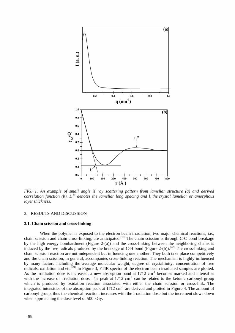
0.2 0.4 0.6 0.8 1.0
I (a.
u.)
q (nm-1)
(a)
0 100 200 300 400 500 600 700 800-0.6
-0.4
-0.2
0.0
0.2
0.4
0.6
0.8
1.0 (b)
lc
γ 1,r/Q
r (Å )
LcM
FIG. 1. An example of small angle X ray scattering pattern from lamellar structure (a) and derived correlation function (b). Lc
M denotes the lamellar long spacing and lc the crystal lamellar or amorphous layer thickness.
3. RESULTS AND DISCUSSION 3.1. Chain scission and cross-linking
When the polymer is exposed to the electron beam irradiation, two major chemical reactions, i.e., chain scission and chain cross-linking, are anticipated.[13] The chain scission is through C-C bond breakage by the high energy bombardment (Figure 2-(a)) and the cross-linking between the neighboring chains is induced by the free radicals produced by the breakage of C-H bond (Figure 2-(b)).[22] The cross-linking and chain scission reaction are not independent but influencing one another. They both take place competitively and the chain scission, in general, accompanies cross-linking reaction. The mechanism is highly influenced by many factors including the average molecular weight, degree of crystallinity, concentration of free radicals, oxidation and etc.[24] In Figure 3, FTIR spectra of the electron beam irradiated samples are plotted. As the irradiation dose is increased, a new absorption band at 1712 cm-1 becomes marked and intensifies with the increase of irradiation dose. The peak at 1712 cm-1 can be related to the ketonic carbonyl group which is produced by oxidation reaction associated with either the chain scission or cross-link. The integrated intensities of the absorption peak at 1712 cm-1 are derived and plotted in Figure 4. The amount of carbonyl group, thus the chemical reaction, increases with the irradiation dose but the increment slows down when approaching the dose level of 500 kGy.
98
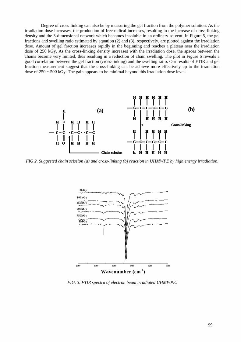
Degree of cross-linking can also be by measuring the gel fraction from the polymer solution. As the irradiation dose increases, the production of free radical increases, resulting in the increase of cross-linking density and the 3-dimensional network which becomes insoluble in an ordinary solvent. In Figure 5, the gel fractions and swelling ratio estimated by equation (2) and (3), respectively, are plotted against the irradiation dose. Amount of gel fraction increases rapidly in the beginning and reaches a plateau near the irradiation dose of 250 kGy. As the cross-linking density increases with the irradiation dose, the spaces between the chains become very limited, thus resulting in a reduction of chain swelling. The plot in Figure 6 reveals a good correlation between the gel fraction (cross-linking) and the swelling ratio. Our results of FTIR and gel fraction measurement suggest that the cross-linking can be achieve more effectively up to the irradiation dose of 250 ~ 500 kGy. The gain appears to be minimal beyond this irradiation dose level.
H
C C C C
O
H
C C
O H H H H
H H H HH
Chain scission
H
C C C C
O
H
C C
O H H H H
H H H HH
H
C C C C
O
H
C C
O H H H H
H H H HH
Chain scission
(a)H
C C C C
O
H
C C
O H H H H
H H H HH
Chain scission
H
C C C C
O
H
C C
O H H H H
H H H HH
H
C C C C
O
H
C C
O H H H H
H H H HH
Chain scission
(a) C C
H H
H
C C
H H
H H
C C
H H
H H
C C
H
H
C C
H H
H H
C C
H H
H HH
Cross-linking
C C
H H
H
C C
H H
H H
C C
H H
H H
C C
H
H
C C
H H
H H
C C
H H
H HH
C C
H H
H
C C
H H
H H
C C
H H
H H
C C
H
H
C C
H H
H H
C C
H H
H HH
Cross-linking
(b)C C
H H
H
C C
H H
H H
C C
H H
H H
C C
H
H
C C
H H
H H
C C
H H
H HH
Cross-linking
C C
H H
H
C C
H H
H H
C C
H H
H H
C C
H
H
C C
H H
H H
C C
H H
H HH
C C
H H
H
C C
H H
H H
C C
H H
H H
C C
H
H
C C
H H
H H
C C
H H
H HH
Cross-linking
(b)
FIG 2. Suggested chain scission (a) and cross-linking (b) reaction in UHMWPE by high energy irradiation.
2000 1800 1600 1400 1200 1000
Wavenumber (cm-1)
0kGy
100kGy
250kGy
500kGy
750kGy
1MGy
FIG. 3. FTIR spectra of electron beam irradiated UHMWPE.
99

0 250 500 750 10000.3
0.4
0.5
0.6
0.7
0.8
0.9
1.0
Aso
rptio
nn a
rea
Irradiation dose (kGy)
FIG. 4. Plot of integrated intensities of absorption bands at 1712 cm-1 vs. irradiation dose.
0 250 500 750 100030
45
60
75
90 Swelling ratio (%
)Gel
frac
tion
(%)
0
3
6
9
12
15
Irradiation dose (kGy)
FIG. 5. Plot of gel fraction and swelling ratio vs. irradiation dose.
30 40 50 60 70 80 90 1000
3
6
9
12
15
18
Gel (%)
Swel
ling
ratio
(%)
FIG. 6. Correlation between the degree of gel fraction(cross-linking) and swelling ratio.
100
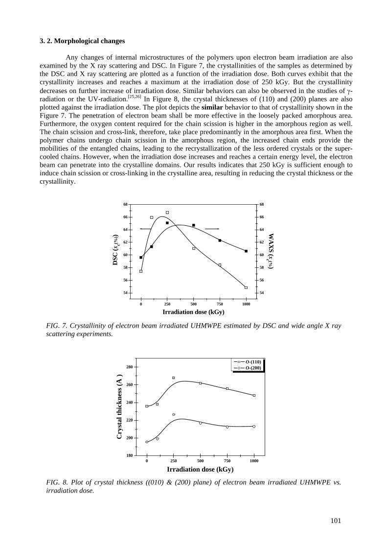
3. 2. Morphological changes
Any changes of internal microstructures of the polymers upon electron beam irradiation are also examined by the X ray scattering and DSC. In Figure 7, the crystallinities of the samples as determined by the DSC and X ray scattering are plotted as a function of the irradiation dose. Both curves exhibit that the crystallinity increases and reaches a maximum at the irradiation dose of 250 kGy. But the crystallinity decreases on further increase of irradiation dose. Similar behaviors can also be observed in the studies of γ-radiation or the UV-radiation.[25,26] In Figure 8, the crystal thicknesses of (110) and (200) planes are also plotted against the irradiation dose. The plot depicts the similar behavior to that of crystallinity shown in the Figure 7. The penetration of electron beam shall be more effective in the loosely packed amorphous area. Furthermore, the oxygen content required for the chain scission is higher in the amorphous region as well. The chain scission and cross-link, therefore, take place predominantly in the amorphous area first. When the polymer chains undergo chain scission in the amorphous region, the increased chain ends provide the mobilities of the entangled chains, leading to the recrystallization of the less ordered crystals or the super-cooled chains. However, when the irradiation dose increases and reaches a certain energy level, the electron beam can penetrate into the crystalline domains. Our results indicates that 250 kGy is sufficient enough to induce chain scission or cross-linking in the crystalline area, resulting in reducing the crystal thickness or the crystallinity.
0 250 500 750 1000
54
56
58
60
62
64
66
68
54
56
58
60
62
64
66
68
DSC
(Xc(%
))W
AX
S (Xc (%)
Irradiation dose (kGy) FIG. 7. Crystallinity of electron beam irradiated UHMWPE estimated by DSC and wide angle X ray scattering experiments.
0 250 500 750 1000180
200
220
240
260
280
Cry
stal
thic
knes
s (Å
)
Irradiation dose (kGy)
O-(110) O-(200)
FIG. 8. Plot of crystal thickness ((010) & (200) plane) of electron beam irradiated UHMWPE vs. irradiation dose.
101
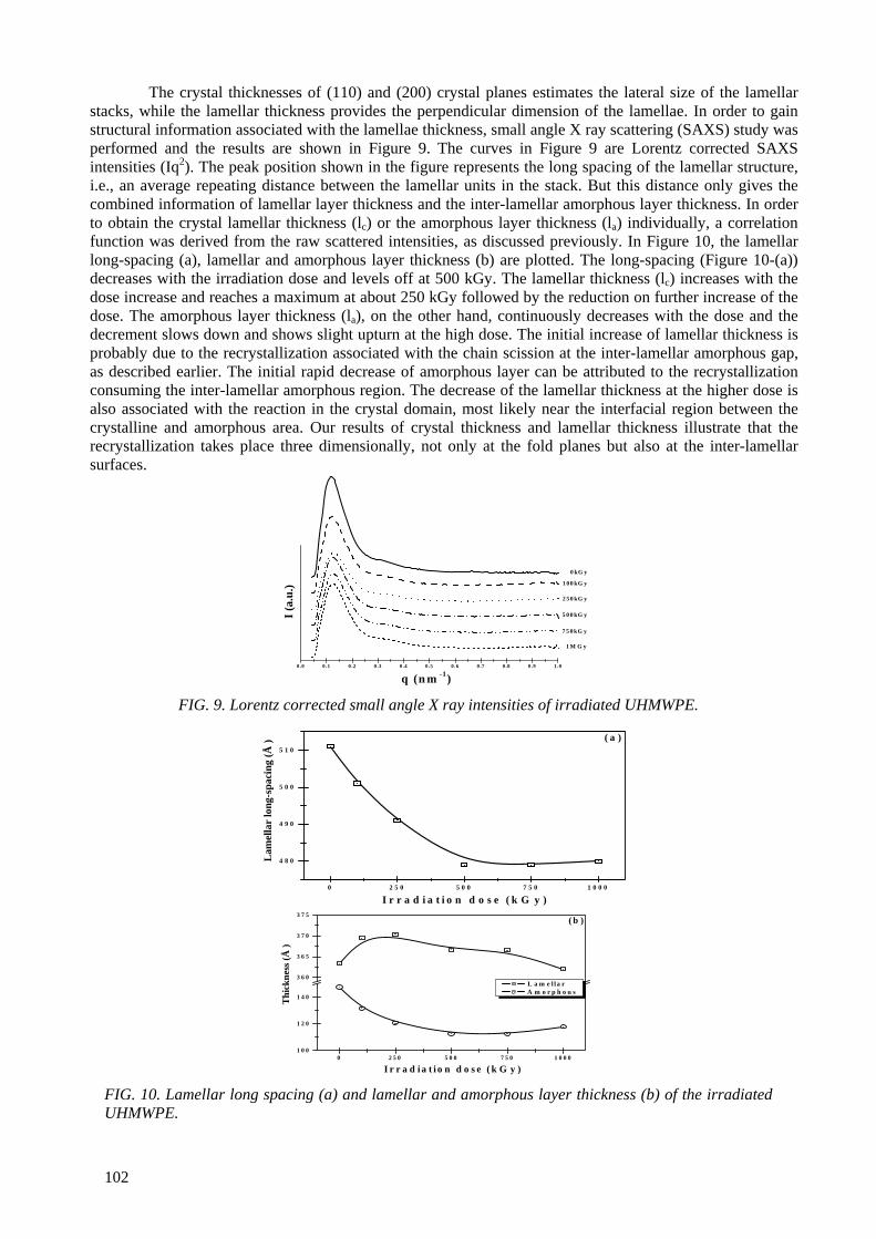
The crystal thicknesses of (110) and (200) crystal planes estimates the lateral size of the lamellar stacks, while the lamellar thickness provides the perpendicular dimension of the lamellae. In order to gain structural information associated with the lamellae thickness, small angle X ray scattering (SAXS) study was performed and the results are shown in Figure 9. The curves in Figure 9 are Lorentz corrected SAXS intensities (Iq2). The peak position shown in the figure represents the long spacing of the lamellar structure, i.e., an average repeating distance between the lamellar units in the stack. But this distance only gives the combined information of lamellar layer thickness and the inter-lamellar amorphous layer thickness. In order to obtain the crystal lamellar thickness (lc) or the amorphous layer thickness (la) individually, a correlation function was derived from the raw scattered intensities, as discussed previously. In Figure 10, the lamellar long-spacing (a), lamellar and amorphous layer thickness (b) are plotted. The long-spacing (Figure 10-(a)) decreases with the irradiation dose and levels off at 500 kGy. The lamellar thickness (lc) increases with the dose increase and reaches a maximum at about 250 kGy followed by the reduction on further increase of the dose. The amorphous layer thickness (la), on the other hand, continuously decreases with the dose and the decrement slows down and shows slight upturn at the high dose. The initial increase of lamellar thickness is probably due to the recrystallization associated with the chain scission at the inter-lamellar amorphous gap, as described earlier. The initial rapid decrease of amorphous layer can be attributed to the recrystallization consuming the inter-lamellar amorphous region. The decrease of the lamellar thickness at the higher dose is also associated with the reaction in the crystal domain, most likely near the interfacial region between the crystalline and amorphous area. Our results of crystal thickness and lamellar thickness illustrate that the recrystallization takes place three dimensionally, not only at the fold planes but also at the inter-lamellar surfaces.
0 .0 0 .1 0 .2 0 .3 0 .4 0 .5 0 .6 0 .7 0 .8 0 .9 1 .0
I (a.
u.)
q (n m -1)
1 M G y
7 5 0 kG y
5 0 0 kG y
2 5 0 kG y
1 0 0 kG y
0 kG y
FIG. 9. Lorentz corrected small angle X ray intensities of irradiated UHMWPE.
0 2 5 0 5 0 0 7 5 0 1 0 0 0
4 8 0
4 9 0
5 0 0
5 1 0
Lam
ella
r lo
ng-s
paci
ng (Å
)
I r r a d i a t i o n d o s e ( k G y )
( a )
0 2 5 0 5 0 0 7 5 0 1 0 0 01 0 0
1 2 0
1 4 0
3 6 0
3 6 5
3 7 0
3 7 5
I r r a d i a t i o n d o s e ( k G y )
Thi
ckne
ss (Å
)
( b )
L a m e l l a r A m o r p h o u s
FIG. 10. Lamellar long spacing (a) and lamellar and amorphous layer thickness (b) of the irradiated UHMWPE.
102
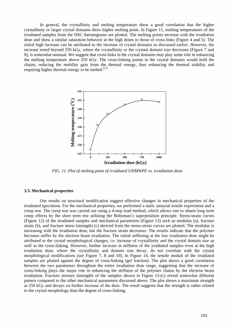
In general, the crystallinity and melting temperature show a good correlation that the higher crystallinity or larger crystal domains show higher melting point. In Figure 11, melting temperatures of the irradiated samples from the DSC thermograms are plotted. The melting points increase with the irradiation dose and show a similar saturation behavior at the high doses to those of cross-links (Figure 4 and 5). The initial high increase can be attributed to the increase of crystal domains as discussed earlier. However, the increase noted beyond 250 kGy, where the crystallinity or the crytstal domain size decreases (Figure 7 and 8), is somewhat unusual. We suggest that cross-links in the crystal domains may play some role in enhancing the melting temperature above 250 kGy. The cross-linking points in the crystal domains would hold the chains, reducing the mobility gain from the thermal energy, thus enhancing the thermal stability and requiring higher thermal energy to be melted.[27]
0 250 500 750 1000135
136
137
138
139
140
141
142
Mel
ting
tem
pera
ture
(o C)
Irradiation dose (kGy) FIG. 11. Plot of melting point of irradiated UHMWPE vs. irradiation dose.
3.3. Mechanical properties
Our results on structural modification suggest effective changes in mechanical properties of the irradiated specimens. For the mechanical properties, we performed a static uniaxial tensile experiment and a creep test. The creep test was carried out using a 4-step load method, which allows one to obtain long term creep effects by the short term test utilizing the Boltzman’s superposition principle. Stress-strain curves (Figure 12) of the irradiated samples and mechanical parameters (Figure 13) such as modulus (a), fracture strain (b), and fracture stress (strength) (c) derived from the stress-strain curves are plotted. The modulus is increasing with the irradiation dose, but the fracture strain decreases. The results indicate that the polymer becomes stiffer by the electron beam irradiation. The initial stiffening at the low irradiation dose might be attributed to the crystal morphological changes, i.e. increase of crystallinity and the crystal domain size as well as the cross-linking. However, further increase in stiffness of the irradiated samples even at the high irradiation dose, where the crystallinity and domain size decay, do not correlate with the crystal morphological modifications (see Figure 7, 8 and 10). In Figure 14, the tensile moduli of the irradiated samples are plotted against the degree of cross-linking (gel fraction). The plot shows a good correlation between the two parameters throughout the entire irradiation dose range, suggesting that the increase of cross-linking plays the major role in enhancing the stiffness of the polymer chains by the electron beam irradiation. Fracture stresses (strength) of the samples shown in Figure 13-(c) reveal somewhat different pattern compared to the other mechanical parameters discussed above. The plot shows a maximum strength at 250 kGy and decays on further increase of the dose. The result suggests that the strength is rather related to the crystal morphology than the degree of cross-linking.
103
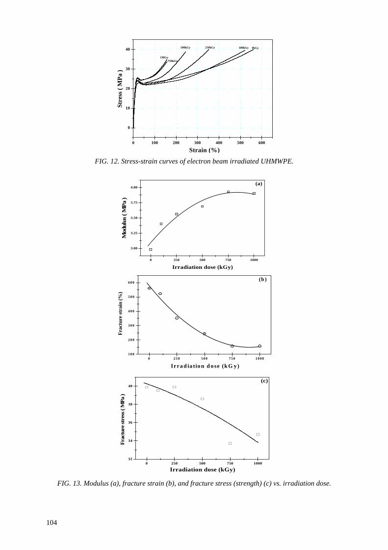
0 100 200 300 400 500 600
0
10
20
30
40
1MGy750kGy
500kGy 250kGy 100kGy
Strain (%)
0kGy
Stre
ss (
MPa
)
FIG. 12. Stress-strain curves of electron beam irradiated UHMWPE.
0 250 500 750 1000
3.00
3.25
3.50
3.75
4.00(a)
Irradiation dose (kGy)
Mod
ulus
( M
Pa )
0 2 5 0 5 0 0 7 5 0 1 0 0 01 0 0
2 0 0
3 0 0
4 0 0
5 0 0
6 0 0
Irra d ia tio n d o se (k G y )
(b )
Fr
actu
re st
rain
(%)
0 250 500 750 100032
34
36
38
40(c)
Irradiation dose (kGy)
Frac
ture
stre
ss (
MPa
)
FIG. 13. Modulus (a), fracture strain (b), and fracture stress (strength) (c) vs. irradiation dose.
104
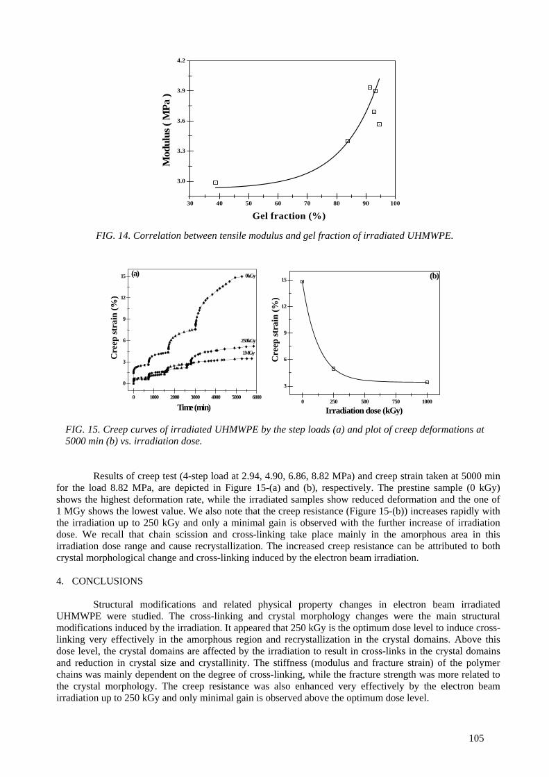
30 40 50 60 70 80 90 100
3.0
3.3
3.6
3.9
4.2
Gel fraction (%)
Mod
ulus
( M
Pa )
FIG. 14. Correlation between tensile modulus and gel fraction of irradiated UHMWPE.
0 1000 2000 3000 4000 5000 6000
0
3
6
9
12
15 (a)
Cre
ep st
rain
(%)
Time (min)
1MGy
250kGy
0kGy
0 250 500 750 1000
3
6
9
12
15 (b)
Irradiation dose (kGy)
Cre
ep st
rain
(%)
FIG. 15. Creep curves of irradiated UHMWPE by the step loads (a) and plot of creep deformations at 5000 min (b) vs. irradiation dose.
Results of creep test (4-step load at 2.94, 4.90, 6.86, 8.82 MPa) and creep strain taken at 5000 min for the load 8.82 MPa, are depicted in Figure 15-(a) and (b), respectively. The prestine sample (0 kGy) shows the highest deformation rate, while the irradiated samples show reduced deformation and the one of 1 MGy shows the lowest value. We also note that the creep resistance (Figure 15-(b)) increases rapidly with the irradiation up to 250 kGy and only a minimal gain is observed with the further increase of irradiation dose. We recall that chain scission and cross-linking take place mainly in the amorphous area in this irradiation dose range and cause recrystallization. The increased creep resistance can be attributed to both crystal morphological change and cross-linking induced by the electron beam irradiation. 4. CONCLUSIONS
Structural modifications and related physical property changes in electron beam irradiated UHMWPE were studied. The cross-linking and crystal morphology changes were the main structural modifications induced by the irradiation. It appeared that 250 kGy is the optimum dose level to induce cross-linking very effectively in the amorphous region and recrystallization in the crystal domains. Above this dose level, the crystal domains are affected by the irradiation to result in cross-links in the crystal domains and reduction in crystal size and crystallinity. The stiffness (modulus and fracture strain) of the polymer chains was mainly dependent on the degree of cross-linking, while the fracture strength was more related to the crystal morphology. The creep resistance was also enhanced very effectively by the electron beam irradiation up to 250 kGy and only minimal gain is observed above the optimum dose level.
105
ACKNOWLEDEGMENT The X ray scattering experiment was performed at 4C1 and 4C2 beamlines in Pohang Accelerator Laboratory, Republic of Korea.
REFERENCES [1] STEIN, H., UHMWPE; Engineered Materials Handbook; Eng. Plastics, ASM International 2 (1992)
167-171. [2] LEE, K. Y. J., KSTLE 3 14 (1998) 46-50. [3] MCDONALD, M.D., BLOEBAUM, R.D., J. Biomed. Mater. Res. 29 (1995) 1. [4] GOLDMAN, M, GRONSKY, R., LONG, G..G.., PRUITT, L., Polym. Degradation & Stability 62
(1998) 97. [5] HARRIS, W.H., Clin. Orthop. 311 (1995) 46. [6] IKADA, Y., NAKAMURA, K., OGATA, S., MAKINO, K., TAJIMA, K., ENDOH, E., HAYASHI,
T., FUJITA, S., FUJISAWA, A., MASTLDA, S., OONISHI, H., J. Po1ym. Sci. Part A 37 (1999) 159. [7] KANG, P. H., NHO, Y. C., Radiation Physics and Chemistry 60 (2001) 79. [8] MAKHLIS, F.A., Radiation physics and chemistry of polymers, New York, Wiley (1975). [9] PRUITT, L., RANGANATANN, R., Mater. Sci. & Eng. C3 (1995) 91. [10] WOO, L., SANDFORD, C. L., Radiation Physics and Chemistry 63 (2002) 845. [11] PREMNATH, V., BELLARE, A., MERRILL, E.W., JASTY, M., HARRIS, W.H., Polymer 40 (1999)
2215. [12] AUSLENDER, V.L., et al., Radiation Physics and Chemistry 63 (2002) 613. [13] DOLE, M.(Ed.), Radiation Chemistry of Macromolecules, Academic Press, New York (1972). [14] GOLDMAN, M., GRONSKY, R., RANGANATHAN, R., PRUITT, L., Polymer 37 (1996) 2909. [15] ELZUBAIR, A., SUAREZ, J. C. M, BONELLI, C. M. C, MANO, E. B., Polymer Testing 22 (2003)
647. [16] MANDELKERN, L., Dole, M., Editor; The radiation chemistry of macromolecules. New York:
Academic Press (1972) 287. [17] KELLER, A., Bassett, D.C., Editor, Developments in crystalline polymers, London, Appl. Sci. 1 (1982)
37. [18] BHATEJA, S.K., Polymer 23 (1982) 654. [19] BHATEJA, S.K., J. Appl. Polym. Sci. 28 (1983) 861. [20] WANG, Y.Q., Li, J., Mater. Sci. & Eng. A266 (1999) 155. [21] LEWIS, G., Biomaterials 22 (2001) 371. [22] LU, S., BUCHANAN, F.J., ORR, J.F., Polym. Testing 21 (2002) 623. [23] ROE, R.J., Methods of X ray and Neutron Scattering in polymer science, New York, Oxford University
Press (2000) 201. [24] STARK, N.M., Matuana, L.M., Polym. Degradation & Stability 86 ( 2004) 1. [25] SEN, M., BASFAR, A.A., Rad. Phys. Chem. 52 (1998) 247. [26] BENSON, R.S., NIM B 191 (2002) 752. [27] DEANIN, R.D., Polymer Structure, Properties and Applications, Cahners Publishing Company, Inc.,
Boston, Massachusetts (1972).
106

ELECTROSPINNING OF POLYCAPROLACTONE AND ITS DEGRADATION EFFECT BY RADIATION YOUNG-CHANG NHO, JOON-PYO JEUN, YOUN-MOOK LIM Radiation Application Research Division, Korea Atomic Energy Research Institute, Jeongup, Republic of Korea
Abstract Nano-to-micro-structured biodegradable polycaprolactone (PCL) nanofibrous scaffolds(NFSs) were prepared by electrospinning of PCL solutions in 8-16%(w/v). Fiber morphology was observed under a scanning electron microscope and effects of instrument parameters including electric voltage, flow rate, and solution parameters such as concentration and solvent, were examined. At high voltage above 10 kV, electrospun PCL fibers exhibited a broad diameter distribution and the morphology structure can be changed by changing the flow rate. With increasing solution concentration, the morphology was changed from beaded fiber to uniform fiber. It was also found that using the non-solvent, the solution viscosity and the thickness of the electrospun fibers could be controlled. PCL NFSs were irradiated using γ ray and their mechanical properties and biodegradability were measured. In vitro/vivo degradation studies of the scaffolds as a function of radiation dose were performed. The scaffolds were degraded more slowly in vitro than in vivo. 1. OBJECTIVES OF THE RESEARCH Electrospinning has recently emerged as a leading technique for generating biomimetic scaffolds made of synthetic and natural polymers for tissue engineering applications. Our objective focuses on the preparation of PCL, biocompatible polymer, nanofibrous scaffolds by electrospinning method for using a candidate bioactive carrier in tissue engineering-based cartilage regeneration scaffolds and their biodegradation study was investigated as a function of radiation dose in vitro and vivo.
2. INTRODUCTION
Electrospinning is a process to easily produce polymeric fibers in the average diameter range of 100 nm-5㎛ [1-4]. The average diameter of the fibers produced this way is at least one or two orders of magnitude smaller than the conventional fiber production methods like melt or solution spinning [5]. As a result, these fibers possess a high aspect ratio that leads to a larger specific surface. These electrospun nanofibers have been suggested to find applications ranging from optical and chemo sensor materials, nanocomposite materials, nanofibers with specific surface chemistry to tissue scaffolds, wound dressings, drug delivery systems, filtration and protective clothing [6-12].
A typical experimental setup of the electrospinning process consists of a syringe-like
apparatus that contains the polymer solution. The narrow end of the syringe is connected to a glass or Teflon capillary. A platinum electrode dipped in the polymer solution is connected to a high voltage DC supply. When the high voltage DC supply is turned on, the electrode imparts an electrical charge to the polymer solution. A jet is ejected from the suspended liquid meniscus at the capillary-end when the applied electric field strength overcomes the surface tension of the liquid. The effects of several process parameters, such as the applied electric field strength, flow rate, concentration, distance between the capillary and the target have been explored in great detail for different polymer materials [1,2,4,5,13]. In the family of synthetic biodegradable polymers, PCL, which is linear, hydrophobic and partially crystalline polyester, is a biodegradable polymer that can be slowly consumed by microorganisms [14]. Its physical properties and commercial availability make it very attractive not only as a substitute for nonbiodegradable polymers of commodity applications but also as a specific plastic of medicine and agricultural areas[15-16]. The main limitation of PCL is its low melting temperature (Tm ~ 65°C), which can be overcome by blending it with other polymers [17].
In the design of a provisional scaffolding material for the fabrication of engineered tissues, a candidate polymer should possess appropriate mechanical properties, which are suitable for target
107
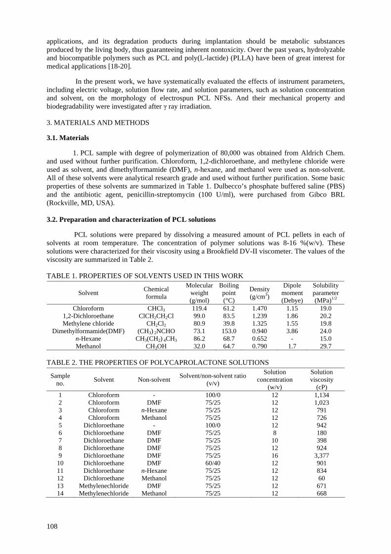
applications, and its degradation products during implantation should be metabolic substances produced by the living body, thus guaranteeing inherent nontoxicity. Over the past years, hydrolyzable and biocompatible polymers such as PCL and poly(L-lactide) (PLLA) have been of great interest for medical applications [18-20].
In the present work, we have systematically evaluated the effects of instrument parameters,
including electric voltage, solution flow rate, and solution parameters, such as solution concentration and solvent, on the morphology of electrospun PCL NFSs. And their mechanical property and biodegradability were investigated after γ ray irradiation. 3. MATERIALS AND METHODS 3.1. Materials
1. PCL sample with degree of polymerization of 80,000 was obtained from Aldrich Chem. and used without further purification. Chloroform, 1,2-dichloroethane, and methylene chloride were used as solvent, and dimethylformamide (DMF), n-hexane, and methanol were used as non-solvent. All of these solvents were analytical research grade and used without further purification. Some basic properties of these solvents are summarized in Table 1. Dulbecco’s phosphate buffered saline (PBS) and the antibiotic agent, penicillin-streptomycin (100 U/ml), were purchased from Gibco BRL (Rockville, MD, USA). 3.2. Preparation and characterization of PCL solutions
PCL solutions were prepared by dissolving a measured amount of PCL pellets in each of solvents at room temperature. The concentration of polymer solutions was 8-16 %(w/v). These solutions were characterized for their viscosity using a Brookfield DV-II viscometer. The values of the viscosity are summarized in Table 2. TABLE 1. PROPERTIES OF SOLVENTS USED IN THIS WORK
Solvent Chemical formula
Molecular weight (g/mol)
Boiling point (°C)
Density (g/cm3)
Dipole moment (Debye)
Solubility parameter (MPa)1/2
Chloroform 1,2-Dichloroethane Methylene chloride
Dimethylformamide(DMF) n-Hexane Methanol
CHCl3 ClCH2CH2Cl
CH2Cl2 (CH3) 2NCHO
CH3(CH2) 4CH3 CH3OH
119.4 99.0 80.9 73.1 86.2 32.0
61.2 83.5 39.8 153.0 68.7 64.7
1.470 1.239 1.325 0.940 0.652 0.790
1.15 1.86 1.55 3.86
- 1.7
19.0 20.2 19.8 24.0 15.0 29.7
TABLE 2. THE PROPERTIES OF POLYCAPROLACTONE SOLUTIONS
Sample no. Solvent Non-solvent Solvent/non-solvent ratio
(v/v)
Solution concentration
(w/v)
Solution viscosity
(cP) 1 2 3 4 5 6 7 8 9
10 11 12 13 14
Chloroform Chloroform Chloroform Chloroform
Dichloroethane Dichloroethane Dichloroethane Dichloroethane Dichloroethane Dichloroethane Dichloroethane Dichloroethane
Methylenechloride Methylenechloride
- DMF
n-Hexane Methanol
- DMF DMF DMF DMF DMF
n-Hexane Methanol
DMF Methanol
100/0 75/25 75/25 75/25 100/0 75/25 75/25 75/25 75/25 60/40 75/25 75/25 75/25 75/25
12 12 12 12 12 8
10 12 16 12 12 12 12 12
1,134 1,023 791 726 942 180 398 924
3,377 901 834 60 671 668
108

FIG. 1. Schematic diagram of electrospinning processes.
3.4. Characterization
The morphology of electrospun PCL NFSs was observed with a JEOL scanning electron microscope(JSM-5200) after gold coating. The fiber diameter of the electrospun fibers was measured by Adobe Photoshop 5.0 software from the SEM pictures. Tensile strength of the PCL NFSs was measured using universal mechanical tester (Instron, model 4443, USA) at room temperature. Dumbbell-shaped specimens of 50 mm long with a neck of 28 and 4 mm wide (ASTM D882) were used. The cross-head speed was fixed at 50 mm/min. Molecular weight changes of the scaffolds were determined by using gel permeation chromatography (GPC). A GPC system composed of a Dynamax Model SD-200, and a refractive index detector (Shodex RI-71) was operated by using two Phenogel 5 columns (pore size 103 Å and 104 Å, 50 × 7.8 mm; Torrance, California) connected in a series as a gel permeation column. 3.5. Biodegradability
The PCL NFSs were irradiated using γ ray from a 60Co source at a dose rate of 10 kGy/h at room temperature (total dose; 50 to 300 kGy). In vitro/in vivo degradation studies of the scaffolds as a function of radiation dose were performed. Afterward, mass erosion of each NFS samples during the degradation period was determined by measuring dry weights and molecular weights of polymeric NFSs.
3.6. Statistical analysis The data were analyzed by ANOVA using SAS (Release 6.12, SAS Institute Inc., Cary, NC, USA) and differences among mean values were processed by Duncan’s multiple range tests. Values of p<0.05 were statistically considered. 4. RESULT AND DISCUSSION 4.1. Effect of voltage
A series of experiments were carried out when the applied voltage was varied from 5 to 25 kV and the tip to target distance was held at 8 cm. Results were shown in Fig. 2. It is known that the fiber diameter increased slightly with increasing applied electric field. In this experiment, a considerable amount of thin fibers with diameters below 100 nm were found when the applied voltage is above 25 kV. A narrow distribution of fiber diameters was observed at a lower voltage of 5 kV, while broad distribution in the fiber diameter was obtained at higher applied voltage of 10-25 kV. Increasing the applied voltage, increasing field strength will increase the electrostatic repulsion force
109

on the fluid jet which favors the thinner fiber formation. Corona discharge was observed a voltage above 30 kV, making electrospinning impossible. 4.2. Effect of flow rate
The morphological structure can be changed by changing the solution flow rate. As shown in Fig. 3, at the flow rate of 0.01 ml/min, big beads were observed. However, by decreasing the flow rate, the morphology was changed from beaded fiber to fiber structure. And as shown in Fig. 4, a narrow distribution of fiber diameters was observed at a lower flow rate of 0.002 ml/min, while broad distribution in the fiber diameter was obtained at higher flow rate 0.008 ml/min. The flow rate could affect electrospinning process. When the flow rate exceeded a critical value, the delivery rate of the solution jet to the capillary tip exceeded the rate at which the solution was removed from the tip by the electric forces. This shift in the mass-balance resulted in sustained but unstable jet and fibers with big beads were formed.
(a) 0 200 400 600 800 1000 1200 1400 1600 1800 2000
0
10
20
30
40
50
Freq
uenc
y di
strib
utio
n (%
)
Fiber diameter (nm)
(b) 0 200 400 600 800 1000 1200 1400 1600 1800 2000
0
10
20
30
40
50
Freq
uenc
y di
strib
utio
n (%
)
Fiber diameter (nm)
(c) 0 200 400 600 800 1000 1200 1400 1600 1800 2000
0
10
20
30
40
50
Freq
uenc
y di
strib
utio
n (%
)
Fiber diameter (nm)
(d) 0 200 400 600 800 1000 1200 1400 1600 1800 2000
0
10
20
30
40
50
Freq
uenc
y di
strib
utio
n (%
)
Fiber diameter (nm)
FIG. 2. Effect of voltage on morphology from 12 %(w/v) PCL/solvent (chloroform/hexane=75/25(v/v)) solution (tip-target distance=8 cm, flow rate=0.005ml/min). Voltage: (a) 5 kV; (b) 10 kV; (c) 15 kV; (d) 25 kV. Original magnification 2kX.
110
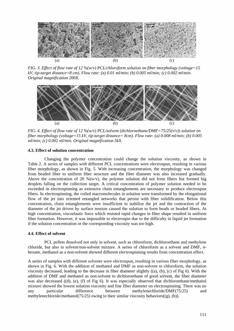
(a) (b) (c)
FIG. 3. Effect of flow rate of 12 %(w/v) PCL/chloroform solution on fiber morphology (voltage=15 kV, tip-target distance=8 cm). Flow rate: (a) 0.01 ml/min; (b) 0.005 ml/min; (c) 0.002 ml/min. Original magnification 200X.
(a) (b) (c)
FIG. 4. Effect of flow rate of 12 %(w/v) PCL/solvent (dichloroethane/DMF=75/25(v/v)) solution on fiber morphology (voltage=15 kV, tip-target distance= 8cm). Flow rate: (a) 0.008 ml/min; (b) 0.005 ml/min; (c) 0.002 ml/min. Original magnification 5kX. 4.3. Effect of solution concentration
Changing the polymer concentration could change the solution viscosity, as shown in Table 2. A series of samples with different PCL concentrations were electrospun, resulting in various fiber morphology, as shown in Fig. 5. With increasing concentration, the morphology was changed from beaded fiber to uniform fiber structure and the fiber diameter was also increased gradually. Above the concentration of 20 %(w/v), the polymer solution did not form fibers but formed big droplets falling on the collection target. A critical concentration of polymer solution needed to be exceeded in electrospinning as extensive chain entanglements are necessary to produce electrospun fibers. In electrospinning, the coiled macromolecules in solution were transformed by the elongational flow of the jet into oriented entangled networks that persist with fiber solidification. Below this concentration, chain entanglements were insufficient to stabilize the jet and the contraction of the diameter of the jet driven by surface tension caused the solution to form beads or beaded fibers. At high concentration, viscoelastic force which resisted rapid changes in fiber shape resulted in uniform fiber formation. However, it was impossible to electrospin due to the difficulty in liquid jet formation if the solution concentration or the corresponding viscosity was too high.
4.4. Effect of solvent
PCL pellets dissolved not only in solvent, such as chloroform, dichloroethane and methylene chloride, but also in solvent/non-solvent mixture. A series of chloroform as a solvent and DMF, n-hexane, methanol as a non-solvent showed different electrospinning results from concentration effect.
A series of samples with different solvents were electrospun, resulting in various fiber morphology, as shown in Fig. 6. With the addition of methanol and DMF as non-solvent to chloroform, the solution viscosity decreased, leading to the decrease in fiber diameter slightly ((a), (b), (c) of Fig 6). With the addition of DMF and methanol as non-solvent to dichloroethane of good solvent, the fiber diameter was also decreased ((d), (e), (f) of Fig 6). It was especially observed that dichloroethane/methanol mixture showed the lowest solution viscosity and fine fiber diameter on electrospinning. There was no any particular difference between methylenechloride/DMF(75/25) and methylenechloride/methanol(75/25) owing to their similar viscosity behaviors((g), (h)).
111

(a) (b)
(c) (d)
FIG. 5. SEM micrographs of electrospun fibers from PCL solution with different solution concentration (solvent : dichloroethane/DMF=75/25 (v/v), voltage=15 kV, flow rate=0.005 ml/min). PCL concentration; (a) 8 %; (b) 10 %; (c) 12 %; (d) 16 %.
(a) (b) (c)
(d) (e) (f)
(g) (h)
FIG. 6. SEM micrographs of electrospun fibers from PCL solutions with different solvents and concentrations (voltage=15 kV, flow rate=0.005ml/min). solvent; (a) chloroform(solution concentration-12 %(w/v)); (b) chloroform/DMF=75/25(v/v)(12 %(w/v)); (c) chloroform/methanol=75/25(v/v) (12 %(w/v)); (d) dichloroethane(12 %(w/v)); (e) dichloroethane/DMF=75/25(v/v)(12 %(w/v)); (f) dichloroethane/methanol=75/25(v/v)(12%(w/v)); (g) methylenechloride/DMF=75/25(v/v)(12 %(w/v)); (h) methylenechloride/methanol=75/25(v/v) (12%(w/v)).
112
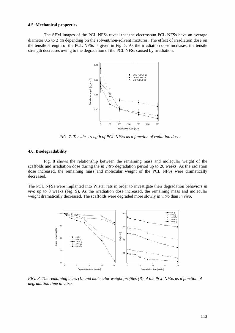
4.5. Mechanical properties
The SEM images of the PCL NFSs reveal that the electrospun PCL NFSs have an average diameter 0.5 to 2 ㎛ depending on the solvent/non-solvent mixtures. The effect of irradiation dose on the tensile strength of the PCL NFSs is given in Fig. 7. As the irradiation dose increases, the tensile strength decreases owing to the degradation of the PCL NFSs caused by irradiation.
(b)
Radiation dose [kGy]
0 50 100 150 200 250 300
Tens
ile s
treng
th [k
g f/mm
2 ]
0.10
0.15
0.20
0.25
DCE 75/DMF 25CF 75/DMF 25MC 75/DMF 25
(a) FIG. 7. Tensile strength of PCL NFSs as a function of radiation dose.
4.6. Biodegradability
Fig. 8 shows the relationship between the remaining mass and molecular weight of the scaffolds and irradiation dose during the in vitro degradation period up to 20 weeks. As the radiation dose increased, the remaining mass and molecular weight of the PCL NFSs were dramatically decreased.
The PCL NFSs were implanted into Wistar rats in order to investigate their degradation behaviors in vivo up to 8 weeks (Fig. 9). As the irradiation dose increased, the remaining mass and molecular weight dramatically decreased. The scaffolds were degraded more slowly in vitro than in vivo.
Degradation time [weeks]
0 5 10 15 20
Mas
s re
mai
ning
[%]
60
70
80
90
100
0 kGy 50 kGy 100 kGy 200 kGy 300 kGy
Degradation time [weeks]
0 5 10 15 20
Mn
[X10
3 ]
20
40
60
80 0 kGy 50 kGy 100 kGy 200 kGy 300 kGy
FIG. 8. The remaining mass (L) and molecular weight profiles (R) of the PCL NFSs as a function of degradation time in vitro.
113
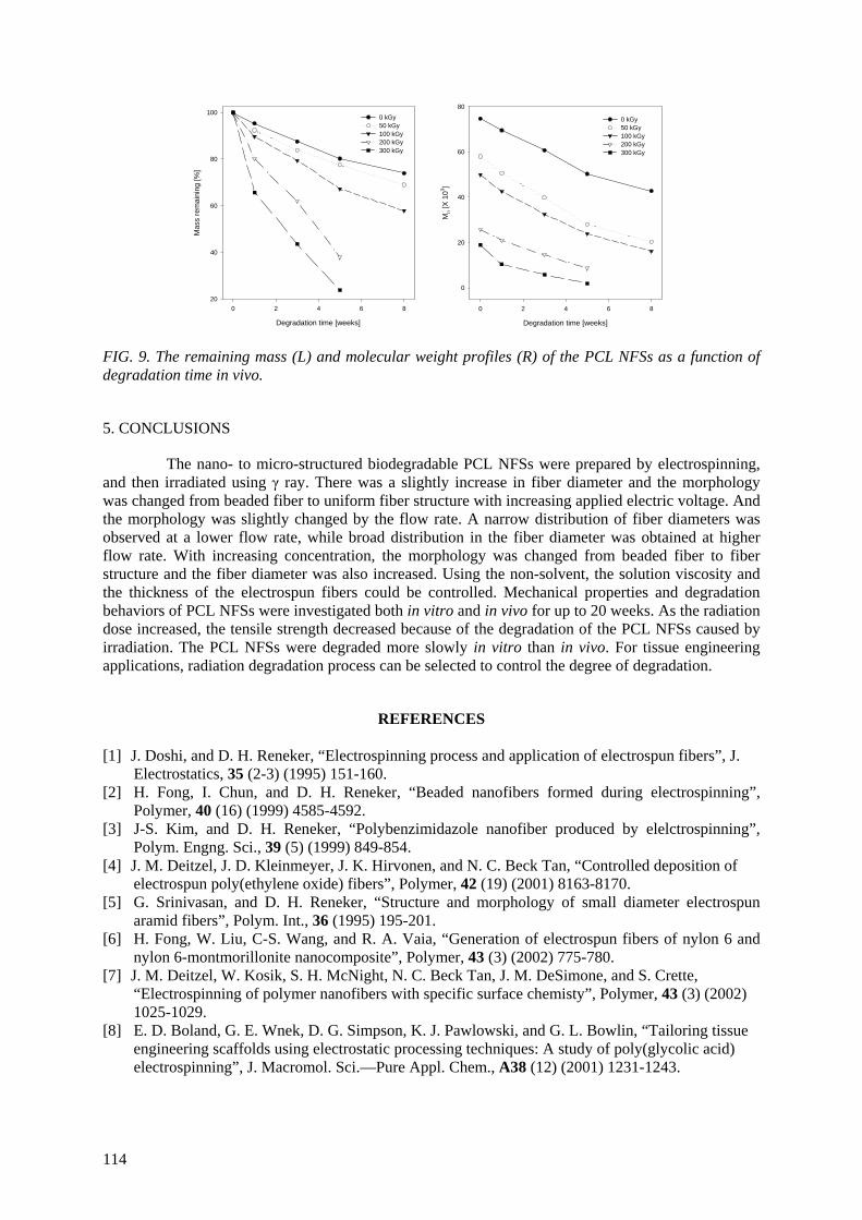
Degradation time [weeks]
0 2 4 6 8
Mas
s re
mai
ning
[%]
20
40
60
80
1000 kGy 50 kGy 100 kGy 200 kGy 300 kGy
Degradation time [weeks]
0 2 4 6 8
Mn [
X 10
3 ]
0
20
40
60
80
0 kGy 50 kGy 100 kGy 200 kGy 300 kGy
FIG. 9. The remaining mass (L) and molecular weight profiles (R) of the PCL NFSs as a function of degradation time in vivo. 5. CONCLUSIONS
The nano- to micro-structured biodegradable PCL NFSs were prepared by electrospinning, and then irradiated using γ ray. There was a slightly increase in fiber diameter and the morphology was changed from beaded fiber to uniform fiber structure with increasing applied electric voltage. And the morphology was slightly changed by the flow rate. A narrow distribution of fiber diameters was observed at a lower flow rate, while broad distribution in the fiber diameter was obtained at higher flow rate. With increasing concentration, the morphology was changed from beaded fiber to fiber structure and the fiber diameter was also increased. Using the non-solvent, the solution viscosity and the thickness of the electrospun fibers could be controlled. Mechanical properties and degradation behaviors of PCL NFSs were investigated both in vitro and in vivo for up to 20 weeks. As the radiation dose increased, the tensile strength decreased because of the degradation of the PCL NFSs caused by irradiation. The PCL NFSs were degraded more slowly in vitro than in vivo. For tissue engineering applications, radiation degradation process can be selected to control the degree of degradation.
REFERENCES [1] J. Doshi, and D. H. Reneker, “Electrospinning process and application of electrospun fibers”, J.
Electrostatics, 35 (2-3) (1995) 151-160. [2] H. Fong, I. Chun, and D. H. Reneker, “Beaded nanofibers formed during electrospinning”,
Polymer, 40 (16) (1999) 4585-4592. [3] J-S. Kim, and D. H. Reneker, “Polybenzimidazole nanofiber produced by elelctrospinning”,
Polym. Engng. Sci., 39 (5) (1999) 849-854. [4] J. M. Deitzel, J. D. Kleinmeyer, J. K. Hirvonen, and N. C. Beck Tan, “Controlled deposition of
electrospun poly(ethylene oxide) fibers”, Polymer, 42 (19) (2001) 8163-8170. [5] G. Srinivasan, and D. H. Reneker, “Structure and morphology of small diameter electrospun
aramid fibers”, Polym. Int., 36 (1995) 195-201. [6] H. Fong, W. Liu, C-S. Wang, and R. A. Vaia, “Generation of electrospun fibers of nylon 6 and
nylon 6-montmorillonite nanocomposite”, Polymer, 43 (3) (2002) 775-780. [7] J. M. Deitzel, W. Kosik, S. H. McNight, N. C. Beck Tan, J. M. DeSimone, and S. Crette,
“Electrospinning of polymer nanofibers with specific surface chemisty”, Polymer, 43 (3) (2002) 1025-1029.
[8] E. D. Boland, G. E. Wnek, D. G. Simpson, K. J. Pawlowski, and G. L. Bowlin, “Tailoring tissue engineering scaffolds using electrostatic processing techniques: A study of poly(glycolic acid) electrospinning”, J. Macromol. Sci.—Pure Appl. Chem., A38 (12) (2001) 1231-1243.
114
[9] J. A. Matthews, G. E. Wnek, D. G. Simpson, and G. L. Bowlin, “Electrospinning of collagen nanofibers”, Biomacromolecules, 3 (2001) 232-238.
[10] E-R. Kenaway, G. L. Bowlin, K. Mansfield, J. Layman, D. G. Simpson, E. H. Sanders, and G. E. Wnek, “Release of tetracycline hydrochloride from electrospun poly(ethylene-co-vinylacetate), poly(lactic acid), and a blend”, J. Controlled Release, 81 (2002) 57-64.
[11] P. Gibson, H. Schreuder-Gibson, and C. J. Pentheny, “Electrospinning technology: Direct application of tailorable ultrathin membranes”, Coated Fabrics, 28 (1998) 63-72.
[12] P. Gibson, H. Schreuder-Gibson, and D. Rivin, “Transport properties of porous membranes based on electrospun nanofibers”, Colloids Surf, A: Physicochem Engng. Aspects, 187–188 (2001) 469-481.
[13] M. M. Demir, I. Yilgor, E. Yilgor, and B. Erman, “Electrospinning of polyurethane fibers”, Polymer, 43 (11) (2002) 3303-3309.
[14] S. J. Hung and P. G. Edelman, Degradable polymers: principles and applications. Scott G and Gilead D Eds., chapter 2, Chapman & Hall, London (1995).
[15] P. Dubois, C. Jacobs, R. Jerome, and P. Teyssie, “Macromolecular engineering of polylactones and polylactides. 4. Mechanism and kinetics of lactide homopolymerization by aluminum isopropoxide”, Macromolecules, 24 (9) (1991) 2266-2270.
[16] J. E. Potts, and H. G. Jelinek. Ed. Aspect degradation and stabilization of polymers. Amsterdam, (1965).
[17] C. D. Kesel, C. V. Wauven, and C. David, “Biodegradation of polycaprolactone and its blends with poly(vinylalcohol) by micro-organisms from a compost of house-hold refuse “, Polym. Degrad. Stab., 55 (1997) 107-113.
[18] M. Li, M. J. Mondrinos, M. R. Gandhi, F. K. Ko, A. S. Weiss and P. J. Lelkes, “Electrospun protein fibers as matrices for tissue engineering”, Biomaterials, 26 (2005) 5999-6008.
[19] I. K. Kwon, S. Kidoaki and T. Matsuda, Electrospun nano- to microfiber fabrics made of biodegradable copolyesters: structural characteristics, mechanical properties and cell adhesion potential, Biomaterials, 26 (2005) 3929-3939.
[20] H. Inoguchi, I. K. Kwon, E. Inoue, K. Takamizawa, Y. Maehara and T. Matsuda, “Mechanical responses of a compliant electrospun poly(l-lactide-co-ε-caprolactone) small-diameter vascular graft”, Biomaterials, 27 (2006) 1470-1478.
115

MITIGATION OF DEGRADATION BY DIFFERENT CLASS OF ANTIOXIDANTS IN LDPE EXPOSE TO IONIZING RADIATIONS D T. YASIN, S. AHMED, Z.I. ZAFAR Advanced Polymer Laboratory, Pakistan Institute of Engineering and Applied Sciences, Islamabad, Pakistan Abstract
The photooxidation and yellowing of low density polyethylene in the presence of different antioxidants upon radiation was monitored by yellowness index tester. This discoloration during irradiation can be controlled by the addition of appropriate antioxidants in LDPE. Thin films of LDPE/antioxidant (thickness range of 150-250 micron) were prepared to measure the loss of antioxidants during processing and irradiation at different doses up to 100 kGy using FTIR and UV-VIS Spectroscopy. Extraction studies with chloroform showed that maximum amount of antioxidant were present unutilised in the samples irradiated at low doses. Whereas samples irradiated at higher doses showed retention of antioxidant in the polymer matrix. This low rate of diminution of antioxidants in LDPE film irradiated at higher doses could be because part of the antioxidant might be bound to polymer matrix through covalent bond and thus unextractable.
1. INTRODUCTION Polyolefins materials are susceptible to thermal and oxidative degradation in every stage of
their life cycle i.e. during manufacturing, processing, storage and irradiations. The basic mechanism of all kinds of oxidations is similar [1-3]. Because of this fact, these materials cannot be used in practical applications as such, unless they are stabilised with some efficient and appropriate antioxidant.
Approximately 70% of LDPE are employed in film manufacturing. These films are used for
various purposes, e.g. packaging and as covers [4]. For sterilization applications, the polymer must be capable of withstanding sterilization procedures, which are used to destroy pathogens. In present practices, that is usually means withstanding 10-50 kGy of gamma or EB radiation. During the irradiation process, oxidative degradation takes place with potential loss of mechanical properties and discoloration. Appropriate stabilizing additives are necessary for stabilization of properties and to avoid discoloration during irradiation and storage [5-6].
In the selection of suitable and effective antioxidant, attention must be paid to the nature of
antioxidant, its compatibility with the polymer, toxicity, volatilization during processing, influence on the stability of polymer and the resultant degradation product. Generally, the loss of antioxidant in polyolefins is caused by migration of antioxidant to the surrounding medium, oxidation of the antioxidant and internal precipitation of the antioxidants as small crystals. Earlier work revealed that the fraction of antioxidant is consumed during stabilisation as compared to the amount lost by physical mechanisms such as diffusion and transfer from the polymer phase to the surrounding medium [7-8]. Moreover, physical loss of antioxidants from polymer matrix constitutes a major concern in the environmental issues and safety regulations.
The measurement of the antioxidant’s concentration in the processed and irradiated materials
is a difficult task due to the presence of the antioxidant in the insoluble polymer matrix, the high reactivity and low stability of the antioxidant and the low antioxidant concentration. Various procedures for the extraction and quantification of antioxidants from polymers have been reported in literature [9-10]. Solvent extraction is used to remove additives from the polymers. The extraction of additives from polymer matrix depends upon the particle size, molecular weight and polarity of the additives. Moreover selection of solvent temperature and extraction time are also very important. Techniques used for quantification of additives are HPLC, GC, FTIR and UV-VIS spectroscopy etc. Each technique has its inherent advantages and disadvantages.
117
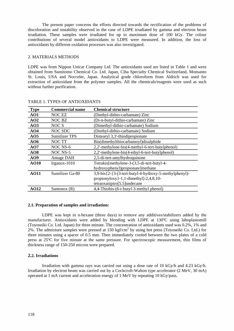
The present paper concerns the efforts directed towards the rectification of the problems of discoloration and instability observed in the case of LDPE irradiated by gamma and electron beam irradiation. These samples were irradiated for up to maximum dose of 100 kGy. The colour contributions of several model antioxidants to LDPE were measured. In addition, the loss of antioxidants by different oxidation processes was also investigated.
2. MATERIALS METHODS LDPE was from Nippon Unicar Company Ltd. The antioxidants used are listed in Table 1 and were obtained from Sumitomo Chemical Co. Ltd. Japan, Ciba Specialty Chemical Switzerland, Monsanto St. Louis, USA and Nocceler, Japan. Analytical grade chloroform from Aldrich was used for extraction of antioxidant from the polymer samples. All the chemicals/reagents were used as such without further purification. TABLE 1. TYPES OF ANTIOXIDANTS
Type Commercial name Chemical structure AO1 NOC EZ (Diethyl-dithio-carbamate) Zinc AO2 NOC BZ (Di-n-butyl-dithio-carbamate) Zinc AO3 NOC S (Dimethyl-dithio-carbamate) Sodium AO4 NOC SDC (Diethyl-dithio-carbamate) Sodium AO5 Sumilizer TPS Distearyl 3,3'-thiodipropionate AO6 NOC TT Bis(dimethylthiocarbamoyl)disulphide AO7 NOC NS-6 2,2'-methylene-bis(4-methyl-6-tert-butylphenol) AO8 NOC NS-5 2,2'-methylene-bis(4-ethyl-6-tert-butylphenol) AO9 Antage DAH 2,5-di-tert-amylhydroquinone AO10 Irganox-1010 Tetrakis[methylene-3-(3,5-di-tert-butyl-4-
hydroxyphenyl)propionate]methane AO11 Sumilizer Ga-80 3,9-bis{2-{3-(3-tert-butyl-4-hydroxy-5-methylphenyl)-
propionyloxy}-1,1-dimethyl]-2,4,8,10-tetraoxasipiro[5.5]undecane
AO12 Santonox (R) 4,4-Thiobis-(6-t-butyl-3-methyl phenol) 2.1. Preparation of samples and irradiation:
LDPE was kept in n-hexane (three days) to remove any additives/stabilizers added by the manufacturer. Antioxidants were added by blending with LDPE at 130ºC using laboplastomill (Toyoseiki Co. Ltd. Japan) for three minute. The concentration of antioxidants used was 0.2%, 1% and 2%. The admixture samples were pressed at 150 kgf/cm2 by using hot press (Toyoseiki Co. Ltd.) for three minutes using a spacer of 0.5 mm. Then immediately cooled between the two plates of a cold press at 25ºC for five minute at the same pressure. For spectroscopic measurement, thin films of thickness range of 150-250 micron were prepared. 2.2. Irradiations
Irradiation with gamma rays was carried out using a dose rate of 10 kGy/h and 4.23 kGy/h. Irradiation by electron beam was carried out by a Cockcroft-Walton type accelerator (2 MeV, 30 mA) operated at 1 mA current and acceleration energy of 1 MeV by repeating 10 kGy/pass.
118
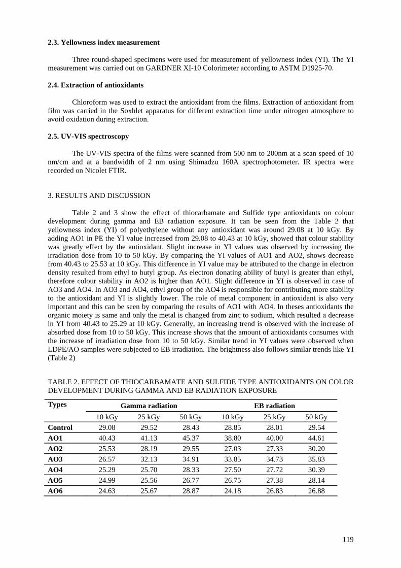
2.3. Yellowness index measurement
Three round-shaped specimens were used for measurement of yellowness index (YI). The YI measurement was carried out on GARDNER XI-10 Colorimeter according to ASTM D1925-70. 2.4. Extraction of antioxidants
Chloroform was used to extract the antioxidant from the films. Extraction of antioxidant from
film was carried in the Soxhlet apparatus for different extraction time under nitrogen atmosphere to avoid oxidation during extraction. 2.5. UV-VIS spectroscopy
The UV-VIS spectra of the films were scanned from 500 nm to 200nm at a scan speed of 10
nm/cm and at a bandwidth of 2 nm using Shimadzu 160A spectrophotometer. IR spectra were recorded on Nicolet FTIR.
3. RESULTS AND DISCUSSION Table 2 and 3 show the effect of thiocarbamate and Sulfide type antioxidants on colour
development during gamma and EB radiation exposure. It can be seen from the Table 2 that yellowness index (YI) of polyethylene without any antioxidant was around 29.08 at 10 kGy. By adding AO1 in PE the YI value increased from 29.08 to 40.43 at 10 kGy, showed that colour stability was greatly effect by the antioxidant. Slight increase in YI values was observed by increasing the irradiation dose from 10 to 50 kGy. By comparing the YI values of AO1 and AO2, shows decrease from 40.43 to 25.53 at 10 kGy. This difference in YI value may be attributed to the change in electron density resulted from ethyl to butyl group. As electron donating ability of butyl is greater than ethyl, therefore colour stability in AO2 is higher than AO1. Slight difference in YI is observed in case of AO3 and AO4. In AO3 and AO4, ethyl group of the AO4 is responsible for contributing more stability to the antioxidant and YI is slightly lower. The role of metal component in antioxidant is also very important and this can be seen by comparing the results of AO1 with AO4. In theses antioxidants the organic moiety is same and only the metal is changed from zinc to sodium, which resulted a decrease in YI from 40.43 to 25.29 at 10 kGy. Generally, an increasing trend is observed with the increase of absorbed dose from 10 to 50 kGy. This increase shows that the amount of antioxidants consumes with the increase of irradiation dose from 10 to 50 kGy. Similar trend in YI values were observed when LDPE/AO samples were subjected to EB irradiation. The brightness also follows similar trends like YI (Table 2) TABLE 2. EFFECT OF THIOCARBAMATE AND SULFIDE TYPE ANTIOXIDANTS ON COLOR DEVELOPMENT DURING GAMMA AND EB RADIATION EXPOSURE
Gamma radiation EB radiation Types
10 kGy 25 kGy 50 kGy 10 kGy 25 kGy 50 kGy Control 29.08 29.52 28.43 28.85 28.01 29.54 AO1 40.43 41.13 45.37 38.80 40.00 44.61 AO2 25.53 28.19 29.55 27.03 27.33 30.20 AO3 26.57 32.13 34.91 33.85 34.73 35.83 AO4 25.29 25.70 28.33 27.50 27.72 30.39 AO5 24.99 25.56 26.77 26.75 27.38 28.14 AO6 24.63 25.67 28.87 24.18 26.83 26.88
119
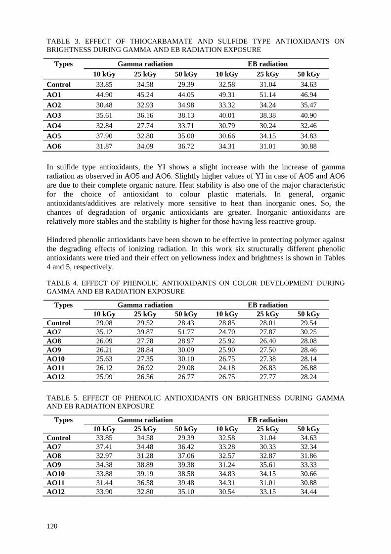
TABLE 3. EFFECT OF THIOCARBAMATE AND SULFIDE TYPE ANTIOXIDANTS ON BRIGHTNESS DURING GAMMA AND EB RADIATION EXPOSURE
Gamma radiation EB radiation Types 10 kGy 25 kGy 50 kGy 10 kGy 25 kGy 50 kGy
Control 33.85 34.58 29.39 32.58 31.04 34.63 AO1 44.90 45.24 44.05 49.31 51.14 46.94 AO2 30.48 32.93 34.98 33.32 34.24 35.47 AO3 35.61 36.16 38.13 40.01 38.38 40.90 AO4 32.84 27.74 33.71 30.79 30.24 32.46 AO5 37.90 32.80 35.00 30.66 34.15 34.83 AO6 31.87 34.09 36.72 34.31 31.01 30.88 In sulfide type antioxidants, the YI shows a slight increase with the increase of gamma radiation as observed in AO5 and AO6. Slightly higher values of YI in case of AO5 and AO6 are due to their complete organic nature. Heat stability is also one of the major characteristic for the choice of antioxidant to colour plastic materials. In general, organic antioxidants/additives are relatively more sensitive to heat than inorganic ones. So, the chances of degradation of organic antioxidants are greater. Inorganic antioxidants are relatively more stables and the stability is higher for those having less reactive group. Hindered phenolic antioxidants have been shown to be effective in protecting polymer against the degrading effects of ionizing radiation. In this work six structurally different phenolic antioxidants were tried and their effect on yellowness index and brightness is shown in Tables 4 and 5, respectively. TABLE 4. EFFECT OF PHENOLIC ANTIOXIDANTS ON COLOR DEVELOPMENT DURING GAMMA AND EB RADIATION EXPOSURE
Gamma radiation EB radiation Types 10 kGy 25 kGy 50 kGy 10 kGy 25 kGy 50 kGy
Control 29.08 29.52 28.43 28.85 28.01 29.54 AO7 35.12 39.87 51.77 24.70 27.87 30.25 AO8 26.09 27.78 28.97 25.92 26.40 28.08 AO9 26.21 28.84 30.09 25.90 27.50 28.46 AO10 25.63 27.35 30.10 26.75 27.38 28.14 AO11 26.12 26.92 29.08 24.18 26.83 26.88 AO12 25.99 26.56 26.77 26.75 27.77 28.24
TABLE 5. EFFECT OF PHENOLIC ANTIOXIDANTS ON BRIGHTNESS DURING GAMMA AND EB RADIATION EXPOSURE
Gamma radiation EB radiation Types 10 kGy 25 kGy 50 kGy 10 kGy 25 kGy 50 kGy
Control 33.85 34.58 29.39 32.58 31.04 34.63 AO7 37.41 34.48 36.42 33.28 30.33 32.34 AO8 32.97 31.28 37.06 32.57 32.87 31.86 AO9 34.38 38.89 39.38 31.24 35.61 33.33 AO10 33.88 39.19 38.58 34.83 34.15 30.66 AO11 31.44 36.58 39.48 34.31 31.01 30.88 AO12 33.90 32.80 35.10 30.54 33.15 34.44
120
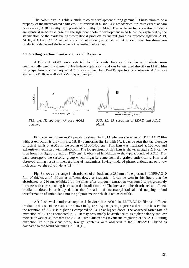
The colour data in Table 4 attribute color development during gamma/EB irradiation to be a property of the incorporated additives. Antioxidant AO7 and AO8 are identical structure except at para position i.e., AO8 has ethyl group instead of methyl (in AO7). The oxidative transformation products are identical in both the case but the significant colour development in AO7 can be explained by the stabilization of the oxidative transformational products by methyl group by hyperconjugation. AO9, AO10, AO11 and AO12 have almost same colour data, which show that their oxidative transformation products is stable and electron cannot be further delocalized.
3.1. Grafting reaction of antioxidants and IR spectra AO10 and AO12 were selected for this study because both the antioxidants were
commercially used in different polyethylene applications and can be analyzed directly in LDPE film using spectroscopic techniques. AO10 was studied by UV-VIS spectroscopy whereas AO12 was studied by FTIR as well as UV-VIS spectroscopy.
FIG. 1A. IR spectrum of pure AO12 powder.
FIG. 1B. IR spectrum of LDPE and AO12 blend.
IR Spectrum of pure AO12 powder is shown in fig 1A whereas spectrum of LDPE/AO12 film without extraction is shown in fig. 1B. By comparing fig. 1B with 1A, it can be seen that the presence of typical bands of AO12 in the region of 1100-1400 cm-1. This film was irradiated at 100 kGy and exhaustively extracted with chloroform. The IR spectrum of this film is shown in figure 2. It can be seen from this figure a bands at 1720 cm-1 is observed in addition to the typical bands of AO12. This band correspond the carbonyl group which might be come from the grafted antioxidants. Kim et al observed similar result in melt grafting of maleimides having hindered phenol antioxidant onto low molecular weight polyethylene [11].
Fig. 3 shows the change in absorbance of antioxidant at 280 nm of the present in LDPE/AO10
film of thickness of 150µm at different doses of irradiation. It can be seen in this figure that the absorbance at 280 nm exhibited by the films after thorough extraction was found to progressively increase with corresponding increase in the irradiation dose The increase in the absorbance at different irradiation doses is probably due to the formation of macroalkyl radical and trapping or/and transformation of antioxidant into the polymer matrix which is not extractable.
AO12 showed similar absorption behaviour like AO10 in LDPE/AO12 film at different
irradiation doses and the results are shown in figure 4. By comparing figure 3 and 4, it can be seen that the retention of AO10 is higher as compared to AO12 at higher doses. The observed faster rate of extraction of AO12 as compared to AO10 may presumably be attributed to its higher polarity and low molecular weight as compared to AO10. These differences favour the migration of the AO12 during extraction. In our previous work, low gel contents were observed in the LDPE/AO12 blend as compared to the blend containing AO10 [10].
121
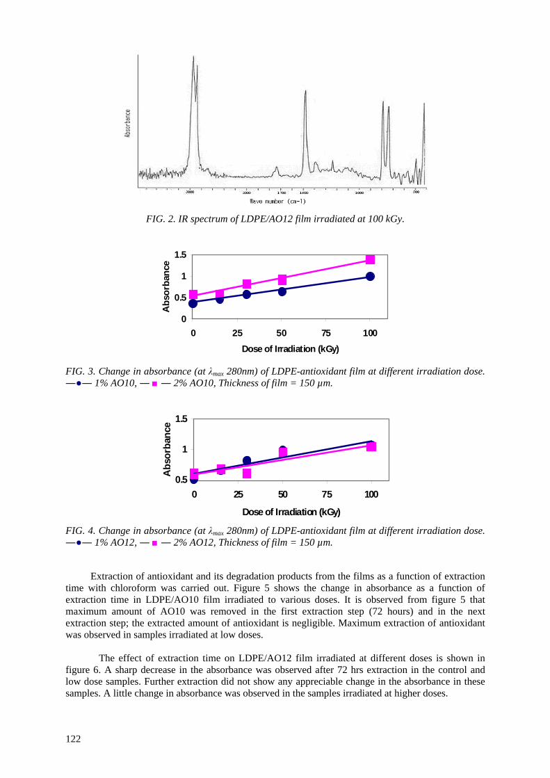
FIG. 2. IR spectrum of LDPE/AO12 film irradiated at 100 kGy.
0
0.5
1
1.5
0 25 50 75 100Dose of Irradiation (kGy)
Abs
orba
nce
FIG. 3. Change in absorbance (at λmax 280nm) of LDPE-antioxidant film at different irradiation dose. ―●― 1% AO10, ― ■ ― 2% AO10, Thickness of film = 150 µm.
0.5
1
1.5
0 25 50 75 10
Dose of Irradiation (kGy)
Abs
orba
nce
0
FIG. 4. Change in absorbance (at λmax 280nm) of LDPE-antioxidant film at different irradiation dose. ―●― 1% AO12, ― ■ ― 2% AO12, Thickness of film = 150 µm.
Extraction of antioxidant and its degradation products from the films as a function of extraction time with chloroform was carried out. Figure 5 shows the change in absorbance as a function of extraction time in LDPE/AO10 film irradiated to various doses. It is observed from figure 5 that maximum amount of AO10 was removed in the first extraction step (72 hours) and in the next extraction step; the extracted amount of antioxidant is negligible. Maximum extraction of antioxidant was observed in samples irradiated at low doses.
The effect of extraction time on LDPE/AO12 film irradiated at different doses is shown in
figure 6. A sharp decrease in the absorbance was observed after 72 hrs extraction in the control and low dose samples. Further extraction did not show any appreciable change in the absorbance in these samples. A little change in absorbance was observed in the samples irradiated at higher doses.
122
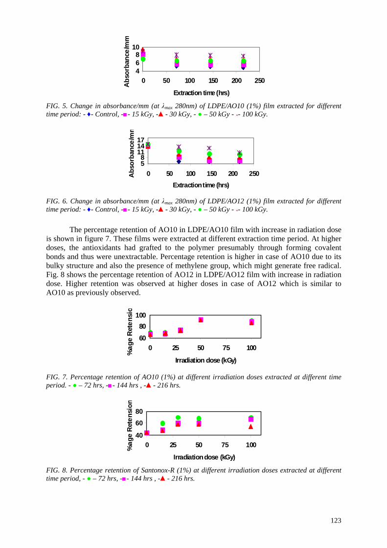
468
10
0 50 100 150 200 250
Extraction time (hrs)
Abs
orba
nce/
mm
FIG. 5. Change in absorbance/mm (at λmax 280nm) of LDPE/AO10 (1%) film extracted for different time period: - ♦- Control, -■- 15 kGy, -▲- 30 kGy, - ● – 50 kGy - *- 100 kGy.
58
111417
0 50 100 150 200 250Extraction time (hrs)
Abs
orba
nce/
mm
FIG. 6. Change in absorbance/mm (at λmax 280nm) of LDPE/AO12 (1%) film extracted for different time period: - ♦- Control, -■- 15 kGy, -▲- 30 kGy, - ● – 50 kGy - *- 100 kGy.
The percentage retention of AO10 in LDPE/AO10 film with increase in radiation dose is shown in figure 7. These films were extracted at different extraction time period. At higher doses, the antioxidants had grafted to the polymer presumably through forming covalent bonds and thus were unextractable. Percentage retention is higher in case of AO10 due to its bulky structure and also the presence of methylene group, which might generate free radical. Fig. 8 shows the percentage retention of AO12 in LDPE/AO12 film with increase in radiation dose. Higher retention was observed at higher doses in case of AO12 which is similar to AO10 as previously observed.
6080
100
0 25 50 75 100
Irradiation dose (kGy)
%ag
e R
eten
sio
FIG. 7. Percentage retention of AO10 (1%) at different irradiation doses extracted at different time period. - ● – 72 hrs, -■- 144 hrs , -▲- 216 hrs.
40
6080
0 25 50 75 100
Irradiation dose (kGy)
%ag
e R
eten
sion
FIG. 8. Percentage retention of Santonox-R (1%) at different irradiation doses extracted at different time period, - ● – 72 hrs, -■- 144 hrs , -▲- 216 hrs.
123
4. CONCLUSIONS The photooxidation and yellowing in LDPE under ionising radiation can be controlled by the
addition of appropriate antioxidants in LDPE. Small structural change or substitutent greatly affects the response of antioxidant during irradiation. Spectroscopic analysis of the irradiated LDPE/antioxidant film showed that a gradual increase in absorbance is observed with increase in irradiation dose which might be due to the retention of antioxidant. Extraction studies with chloroform further support this idea that maximum amount of antioxidant were removed from samples irradiated at low doses. Whereas samples irradiated at higher doses showed retention of antioxidant in the polymer matrix. This low rate of diminution of antioxidants in LDPE film irradiated at higher doses could be because part of the antioxidant might be bound to polymer matrix through covalent bond and thus unextractable.
ACKNOWLEDGEMENT
The authors would like to thank International Atomic Energy Agency for financial support of this work under the CRP contract 12733/R.
REFERENCES
[1] BILLINGHAM, N.C., Scott, G., Editor; Atmospheric oxidation and antioxidants, vol. 2. Amsterdam: Elsevier (1993).
[2] LACOSTE, J., CARLSSON, D.J., “Gamma-, photo-, and thermally initiated oxidation of linear low density polyethylene: a quantitative comparison of oxidation products”, J. Polym. Sci., Part A: Polym.Chem. 30 (1992) 493-500.
[3] GUGUMUS, F., In Plastic Additives Handbook Edited by Gächter and Müller Publ Hanser , Munich (1990) 138-148.
[4] GUGUMUS, F., In Plastic Additives Handbook, (Gächter R., Müller H., Ed.), (1990) 1-100. [5] CLOUGH, R.L., GILLEN, K.T., MALONE, G.M., WALLACE, J.S., “Color Formation in
Irradiated Polymers”, Radiat. Phys. Chem. 48 (1996) 583-594. [6] BARKHUDARYAN, V.G., Alterations of molecular characteristics of polyethylene under the
influence of γ-radiation, Polymer 41, (2000) 2511. [7] LUNDBÄCK, M., HENDENQVIST, M.S., MATTOZZI, A., GEBBE, U.W., “Migration of
Phenolic antioxidants from linear and branched polyethylene”, Polymer Degradation and Stability 91 (2006) 1571-1580.
[8] LUNDBÄCK, M. STRANDBERG, C., ALBERTSSON, A.C., HEDENQVIST, M.S., GEDDE, U.W., “Loss of Stability by migration and chemical reaction of Santonox R in branched polyethylene under anaerobic and aerobic conditions”, Polymer Degradation and Stability 91 (2006) 1071.
[9] NIELSON, R.C., “Recent advances in polyolefin additive analysis”, J of liquid Chromatography 16 (7) (1993) 1625.
[10] AHMED, A., YASIN, T., GHAFFAR, A., “Radiation effects on hindered phenols in paraffin oil, wax and LDPE” Radiation Physics and Chemistry, 68 (2003) 925-931.
[11] KIM, T.H., OH, R.D., “Melt grafting of maleimidies having hindered phenol antioxidant onto low molecular weight polyethylene”, Polymer Degradation and Stability 84 (2004) 499-503.
124

INFLUENCE OF RADIATION ON SOME PHYSICO-CHEMICAL PROPERTIES OF GUM ACACIA T. YASIN, S. AHMED Advanced Polymer Laboratory, Pakistan Institute of Engineering and Applied Sciences, Islamabad, Pakistan Abstract
Controlling of degradation in polysaccharide is also gaining impetus from commercial point of view. Comprehensive studies on the influence of ionizing radiation on the physico-chemical properties of polysaccharides are very important for their applications in different industries. The effect of gamma radiation on gum acacia has been studied and its effect on some physico-chemical properties, as measured by UV spectroscopy and viscometry has been discussed. The gum samples are irradiated in the range of 5 kGy to 25 kGy both in air and vacuum. Samples irradiated under vacuum shows colour stability while viscosity remain unaffected. 1. INTRODUCTION
Gum Acacia has been known for many years and there are no artificial substitutes that match it for quality or cost of the production. There are more than 500 botanically known species of Acacias, distributed through out the tropical and subtropical areas of the world. The most common and commercial gum is derived from Acacia Senegal. Acacia Senegal gum is a natural gummy exudates obtained by tapping the branches of Acacia Senegal tree [1]. The trees are tapped during the dry season approximately from October to May or June of the following year. Gum exudation is favored by the dry hot weather while cold weather may completely stop the process.
Chemically gum acacia consists mainly of high-molecular weight polysaccharides made up of
rhamanose, arabinose, and galactose, glucuronic and 4-o-methylglucuronic acid, calcium, magnesium, potassium, and sodium [1, 2]. The percentage of different sugar residues present in the gum molecule are 41-53% D-galactose, 25-27% L-arabinose, 10-14% L-rhamnose and 12-18% D-glucuronic acid [3]. Gum Acacia forms viscous solutions up to 60% either by dissolving in water or absorbing their own volume of water [4]. Therefore, it can be regarded as 95% soluble fiber according to some recently available test methods. This is due to higher galactose content of gum acacia, which leads to a greater solubility, and hence the solution is possible even at low temperature. The relevance of studies on influence of gamma irradiation on gum originate from the fact that several thousands tons of the gums are utilized in different industry such as food, cosmetics, beverage and pharmaceutical applications [5]. Moreover the use of ionizing radiation as method of increasing shelf-life of food products is becoming increasingly acceptable and gamma irradiation has been suggested as a possible alternate to ethylene oxide for sterilization of gum. However, polysaccharides generally show a decrease in functional properties on irradiation due to attack by the free radicals generated during irradiation processing [6]. The aims of the study are to:
a) Determine physicochemical properties of irradiated gum to assess the effect of irradiation on physicochemical and functional properties of gum Acacia and to see whether these changes add to the structure of gum acacia which make it more useful especially in the food industry; and
b) Examine if there are any degradation changes in gum structure and to determine which parameters of gum Acacia are affected by irradiation.
2. EXPERIMENTAL
Commercially available gum Acacia was obtained from local market and used as such. Samples in solid state were irradiated to simulate the actual condition prevalent during sterilization of bulk quantities for industrial purpose.
125
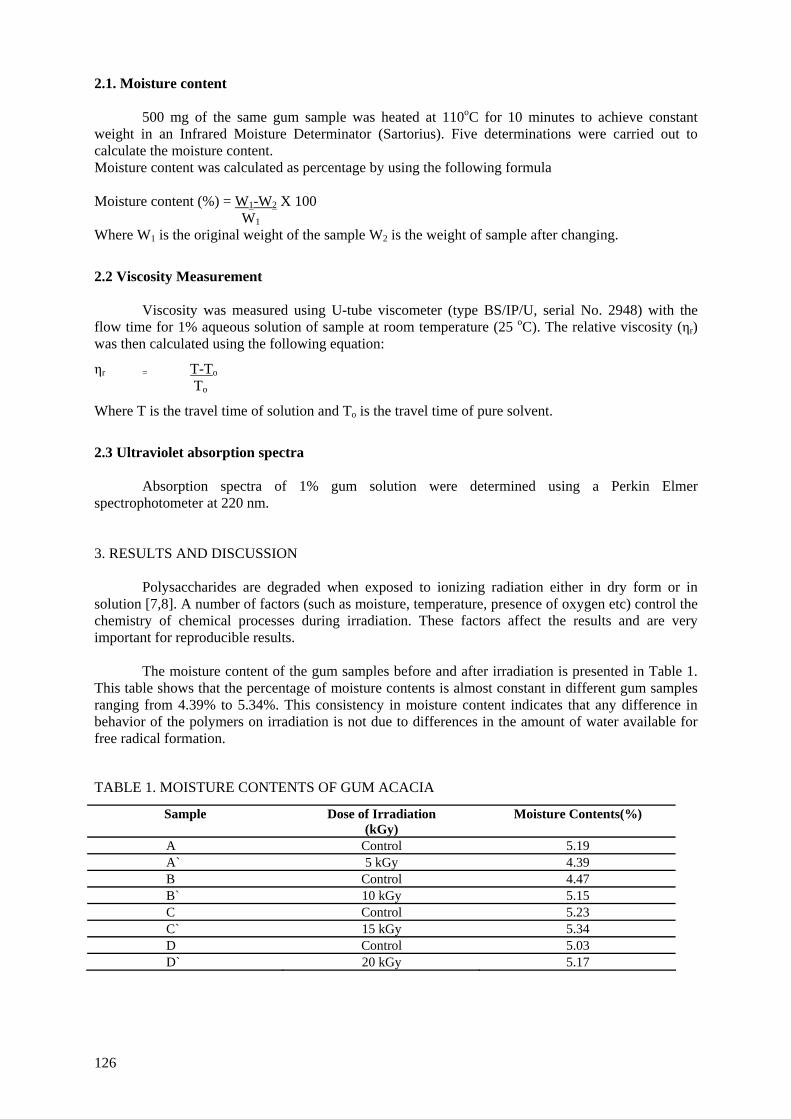
2.1. Moisture content
500 mg of the same gum sample was heated at 110oC for 10 minutes to achieve constant weight in an Infrared Moisture Determinator (Sartorius). Five determinations were carried out to calculate the moisture content. Moisture content was calculated as percentage by using the following formula Moisture content (%) = W1-W2 X 100 W1 Where W1 is the original weight of the sample W2 is the weight of sample after changing.
2.2 Viscosity Measurement
Viscosity was measured using U-tube viscometer (type BS/IP/U, serial No. 2948) with the flow time for 1% aqueous solution of sample at room temperature (25 oC). The relative viscosity (ηr) was then calculated using the following equation:
ηr = T-To To
Where T is the travel time of solution and To is the travel time of pure solvent.
2.3 Ultraviolet absorption spectra
Absorption spectra of 1% gum solution were determined using a Perkin Elmer spectrophotometer at 220 nm. 3. RESULTS AND DISCUSSION
Polysaccharides are degraded when exposed to ionizing radiation either in dry form or in solution [7,8]. A number of factors (such as moisture, temperature, presence of oxygen etc) control the chemistry of chemical processes during irradiation. These factors affect the results and are very important for reproducible results.
The moisture content of the gum samples before and after irradiation is presented in Table 1.
This table shows that the percentage of moisture contents is almost constant in different gum samples ranging from 4.39% to 5.34%. This consistency in moisture content indicates that any difference in behavior of the polymers on irradiation is not due to differences in the amount of water available for free radical formation. TABLE 1. MOISTURE CONTENTS OF GUM ACACIA
Sample Dose of Irradiation (kGy)
Moisture Contents(%)
A Control 5.19 A` 5 kGy 4.39 B Control 4.47 B` 10 kGy 5.15 C Control 5.23 C` 15 kGy 5.34 D Control 5.03 D` 20 kGy 5.17
126
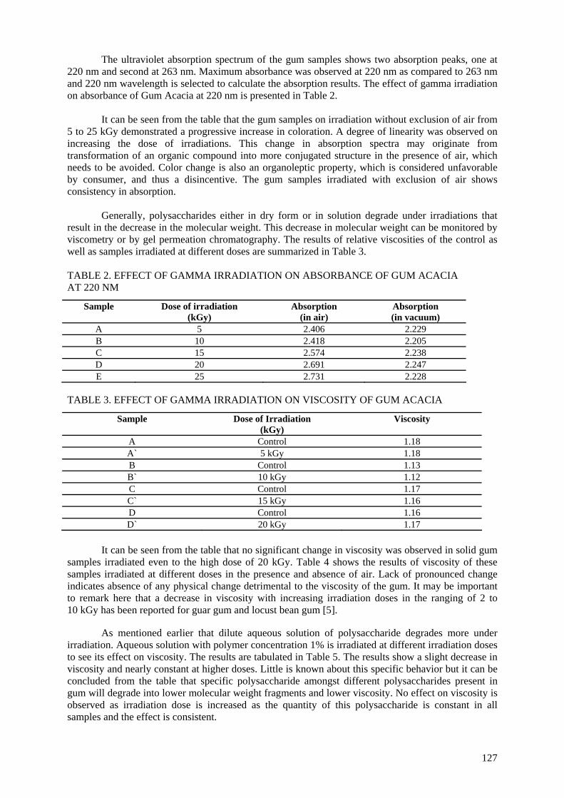
The ultraviolet absorption spectrum of the gum samples shows two absorption peaks, one at 220 nm and second at 263 nm. Maximum absorbance was observed at 220 nm as compared to 263 nm and 220 nm wavelength is selected to calculate the absorption results. The effect of gamma irradiation on absorbance of Gum Acacia at 220 nm is presented in Table 2.
It can be seen from the table that the gum samples on irradiation without exclusion of air from
5 to 25 kGy demonstrated a progressive increase in coloration. A degree of linearity was observed on increasing the dose of irradiations. This change in absorption spectra may originate from transformation of an organic compound into more conjugated structure in the presence of air, which needs to be avoided. Color change is also an organoleptic property, which is considered unfavorable by consumer, and thus a disincentive. The gum samples irradiated with exclusion of air shows consistency in absorption.
Generally, polysaccharides either in dry form or in solution degrade under irradiations that
result in the decrease in the molecular weight. This decrease in molecular weight can be monitored by viscometry or by gel permeation chromatography. The results of relative viscosities of the control as well as samples irradiated at different doses are summarized in Table 3.
TABLE 2. EFFECT OF GAMMA IRRADIATION ON ABSORBANCE OF GUM ACACIA AT 220 NM
Sample Dose of irradiation (kGy)
Absorption (in air)
Absorption (in vacuum)
A 5 2.406 2.229 B 10 2.418 2.205 C 15 2.574 2.238 D 20 2.691 2.247 E 25 2.731 2.228
TABLE 3. EFFECT OF GAMMA IRRADIATION ON VISCOSITY OF GUM ACACIA
Sample Dose of Irradiation (kGy)
Viscosity
A Control 1.18 A` 5 kGy 1.18 B Control 1.13 B` 10 kGy 1.12 C Control 1.17 C` 15 kGy 1.16 D Control 1.16 D` 20 kGy 1.17
It can be seen from the table that no significant change in viscosity was observed in solid gum
samples irradiated even to the high dose of 20 kGy. Table 4 shows the results of viscosity of these samples irradiated at different doses in the presence and absence of air. Lack of pronounced change indicates absence of any physical change detrimental to the viscosity of the gum. It may be important to remark here that a decrease in viscosity with increasing irradiation doses in the ranging of 2 to 10 kGy has been reported for guar gum and locust bean gum [5].
As mentioned earlier that dilute aqueous solution of polysaccharide degrades more under irradiation. Aqueous solution with polymer concentration 1% is irradiated at different irradiation doses to see its effect on viscosity. The results are tabulated in Table 5. The results show a slight decrease in viscosity and nearly constant at higher doses. Little is known about this specific behavior but it can be concluded from the table that specific polysaccharide amongst different polysaccharides present in gum will degrade into lower molecular weight fragments and lower viscosity. No effect on viscosity is observed as irradiation dose is increased as the quantity of this polysaccharide is constant in all samples and the effect is consistent.
127
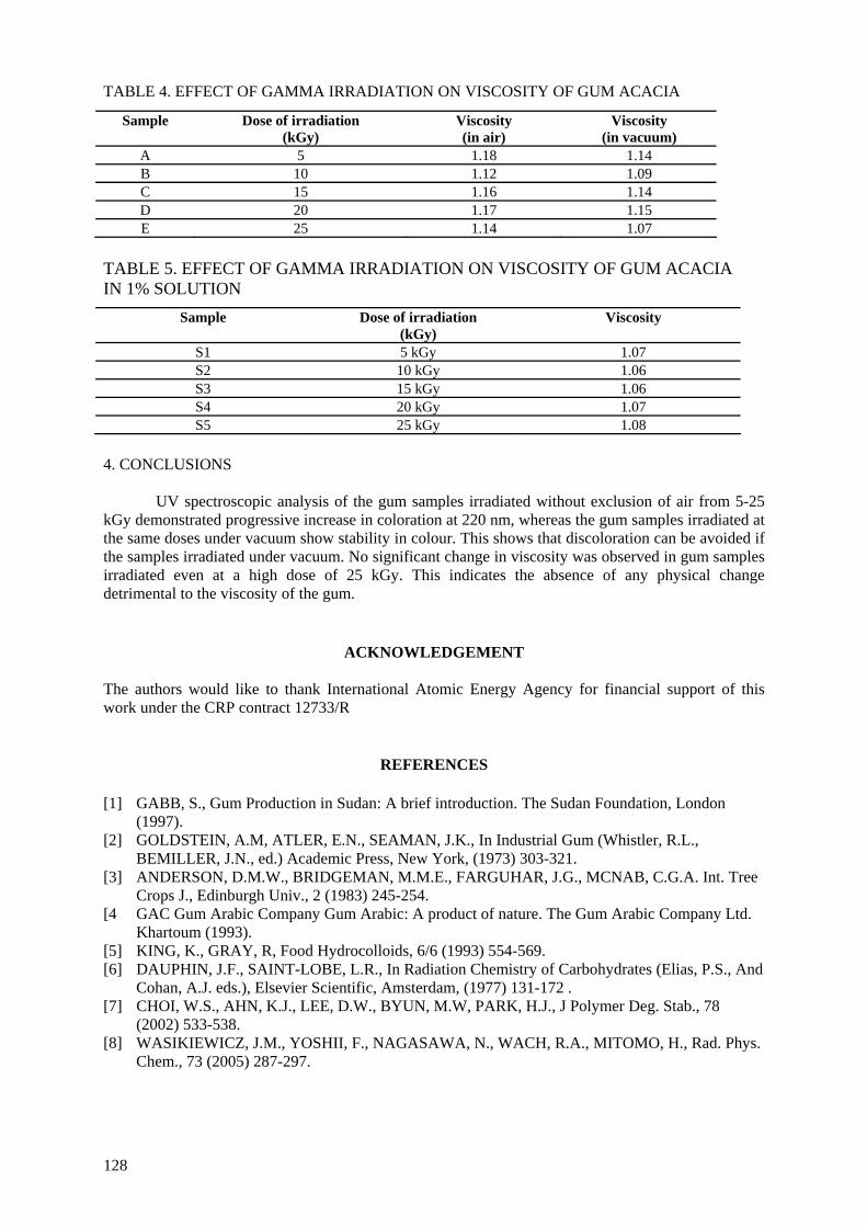
TABLE 4. EFFECT OF GAMMA IRRADIATION ON VISCOSITY OF GUM ACACIA
Sample Dose of irradiation (kGy)
Viscosity (in air)
Viscosity (in vacuum)
A 5 1.18 1.14 B 10 1.12 1.09 C 15 1.16 1.14 D 20 1.17 1.15 E 25 1.14 1.07
TABLE 5. EFFECT OF GAMMA IRRADIATION ON VISCOSITY OF GUM ACACIA IN 1% SOLUTION
Sample Dose of irradiation (kGy)
Viscosity
S1 5 kGy 1.07 S2 10 kGy 1.06 S3 15 kGy 1.06 S4 20 kGy 1.07 S5 25 kGy 1.08
4. CONCLUSIONS
UV spectroscopic analysis of the gum samples irradiated without exclusion of air from 5-25 kGy demonstrated progressive increase in coloration at 220 nm, whereas the gum samples irradiated at the same doses under vacuum show stability in colour. This shows that discoloration can be avoided if the samples irradiated under vacuum. No significant change in viscosity was observed in gum samples irradiated even at a high dose of 25 kGy. This indicates the absence of any physical change detrimental to the viscosity of the gum.
ACKNOWLEDGEMENT
The authors would like to thank International Atomic Energy Agency for financial support of this work under the CRP contract 12733/R
REFERENCES
[1] GABB, S., Gum Production in Sudan: A brief introduction. The Sudan Foundation, London
(1997). [2] GOLDSTEIN, A.M, ATLER, E.N., SEAMAN, J.K., In Industrial Gum (Whistler, R.L.,
BEMILLER, J.N., ed.) Academic Press, New York, (1973) 303-321. [3] ANDERSON, D.M.W., BRIDGEMAN, M.M.E., FARGUHAR, J.G., MCNAB, C.G.A. Int. Tree
Crops J., Edinburgh Univ., 2 (1983) 245-254. [4 GAC Gum Arabic Company Gum Arabic: A product of nature. The Gum Arabic Company Ltd.
Khartoum (1993). [5] KING, K., GRAY, R, Food Hydrocolloids, 6/6 (1993) 554-569. [6] DAUPHIN, J.F., SAINT-LOBE, L.R., In Radiation Chemistry of Carbohydrates (Elias, P.S., And
Cohan, A.J. eds.), Elsevier Scientific, Amsterdam, (1977) 131-172 . [7] CHOI, W.S., AHN, K.J., LEE, D.W., BYUN, M.W, PARK, H.J., J Polymer Deg. Stab., 78
(2002) 533-538. [8] WASIKIEWICZ, J.M., YOSHII, F., NAGASAWA, N., WACH, R.A., MITOMO, H., Rad. Phys.
Chem., 73 (2005) 287-297.
128
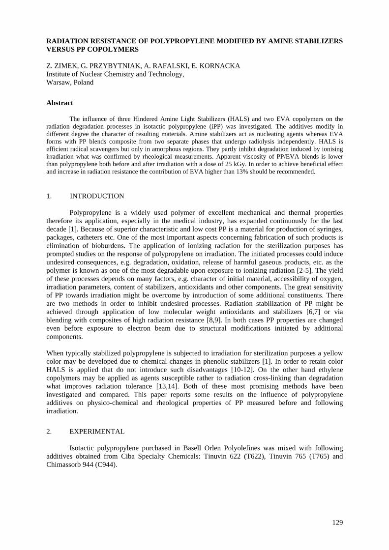
RADIATION RESISTANCE OF POLYPROPYLENE MODIFIED BY AMINE STABILIZERS VERSUS PP COPOLYMERS Z. ZIMEK, G. PRZYBYTNIAK, A. RAFALSKI, E. KORNACKA Institute of Nuclear Chemistry and Technology, Warsaw, Poland
Abstract
The influence of three Hindered Amine Light Stabilizers (HALS) and two EVA copolymers on the radiation degradation processes in isotactic polypropylene (iPP) was investigated. The additives modify in different degree the character of resulting materials. Amine stabilizers act as nucleating agents whereas EVA forms with PP blends composite from two separate phases that undergo radiolysis independently. HALS is efficient radical scavengers but only in amorphous regions. They partly inhibit degradation induced by ionising irradiation what was confirmed by rheological measurements. Apparent viscosity of PP/EVA blends is lower than polypropylene both before and after irradiation with a dose of 25 kGy. In order to achieve beneficial effect and increase in radiation resistance the contribution of EVA higher than 13% should be recommended. 1. INTRODUCTION
Polypropylene is a widely used polymer of excellent mechanical and thermal properties therefore its application, especially in the medical industry, has expanded continuously for the last decade [1]. Because of superior characteristic and low cost PP is a material for production of syringes, packages, catheters etc. One of the most important aspects concerning fabrication of such products is elimination of bioburdens. The application of ionizing radiation for the sterilization purposes has prompted studies on the response of polypropylene on irradiation. The initiated processes could induce undesired consequences, e.g. degradation, oxidation, release of harmful gaseous products, etc. as the polymer is known as one of the most degradable upon exposure to ionizing radiation [2-5]. The yield of these processes depends on many factors, e.g. character of initial material, accessibility of oxygen, irradiation parameters, content of stabilizers, antioxidants and other components. The great sensitivity of PP towards irradiation might be overcome by introduction of some additional constituents. There are two methods in order to inhibit undesired processes. Radiation stabilization of PP might be achieved through application of low molecular weight antioxidants and stabilizers [6,7] or via blending with composites of high radiation resistance [8,9]. In both cases PP properties are changed even before exposure to electron beam due to structural modifications initiated by additional components.
When typically stabilized polypropylene is subjected to irradiation for sterilization purposes a yellow color may be developed due to chemical changes in phenolic stabilizers [1]. In order to retain color HALS is applied that do not introduce such disadvantages [10-12]. On the other hand ethylene copolymers may be applied as agents susceptible rather to radiation cross-linking than degradation what improves radiation tolerance [13,14]. Both of these most promising methods have been investigated and compared. This paper reports some results on the influence of polypropylene additives on physico-chemical and rheological properties of PP measured before and following irradiation.
2. EXPERIMENTAL
Isotactic polypropylene purchased in Basell Orlen Polyolefines was mixed with following additives obtained from Ciba Specialty Chemicals: Tinuvin 622 (T622), Tinuvin 765 (T765) and Chimassorb 944 (C944).
129

T622 T765
C944
Blends were prepared from iPP and two types of random EVA copolymers of varying weight percentages of vinyl acetate (VA) - ELVAX 460 (E1) (18 % VA, MFI 2.5 g/ 10 min, density 0.94 g/cm3) and ELVAX 260 (E2) (28 % VA, MFI 6g/ 10 min, density 0.96 g/cm3) purchased in DuPont Industrial Polymers. Blends PPE1 and PPE2 with wt % of EVA shown in brackets as well as PP modified with 0.5% of HALS were prepared in a Brabender mixer at 180 oC and a rotor speed of 60 rpm, and subsequently compressed between two metal plates quenchnig with water. Samples of the blends were irradiated with a high energy electron beam generated in a linear electron accelerator Elektronika 10/10 (electron energy 10 MeV) to indicated doses (usually to 25 kGy). PP modified with HALS was exposed to ionizing radiation in accelerator LAE 13/9 (electron energy 10 MeV).
EPR spectra were measured using Bruker ESP 300 spectrometer with rectangular TE102 cavity. Relative concentration of radicals in irradiated samples directly upon exposure to ionizing radiation and after indicated periods of time were determined by double integration of spectral areas. DSC measurements were carried out using TA Instruments differential scanning calorimeter (MDSC 2920) for determination of phase transitions. It is equipped with a control unit operating under nitrogen atmosphere at a heating/cooling rate of 10 oC /min. The phase transitions were studied in the temperature range from 25 to 200 oC. About 5 mg of sample inserted in the pan was heated, then kept for 5 min at 200 oC and gradually cooled. Afterwards, the second run was performed applying the same conditions as for the first cycle. Apparent viscosity was measured with CAP 2000+H Brookfield viscometer at temperatures and time of shearing indicated in the figures. 3. RESULTS EPR analysis
The main intermediate generated in polypropylene following irradiation is the third order alkyl radical, that spectrum dominates in EPR signal detected directly upon exposure to electron beam at ambient temperature, Fig.1. Population of the other carbon centered radicals is insignificant. However,
130
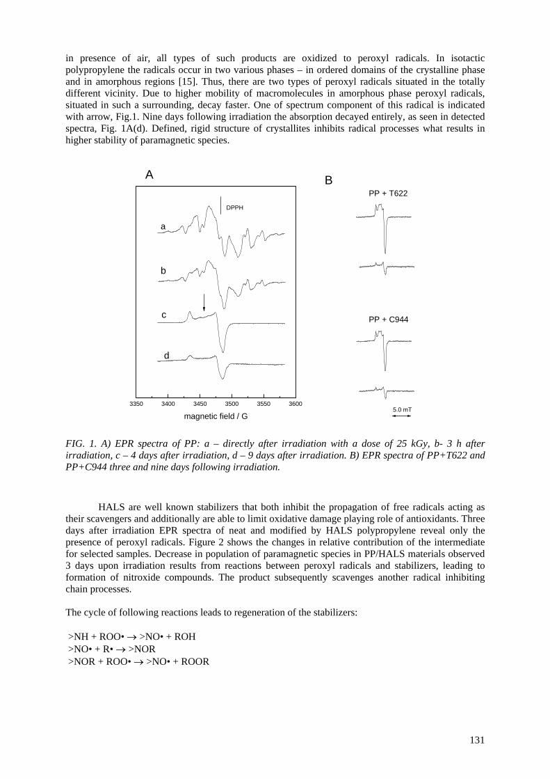
in presence of air, all types of such products are oxidized to peroxyl radicals. In isotactic polypropylene the radicals occur in two various phases – in ordered domains of the crystalline phase and in amorphous regions [15]. Thus, there are two types of peroxyl radicals situated in the totally different vicinity. Due to higher mobility of macromolecules in amorphous phase peroxyl radicals, situated in such a surrounding, decay faster. One of spectrum component of this radical is indicated with arrow, Fig.1. Nine days following irradiation the absorption decayed entirely, as seen in detected spectra, Fig. 1A(d). Defined, rigid structure of crystallites inhibits radical processes what results in higher stability of paramagnetic species.
3350 3400 3450 3500 3550 3600
DPPH
magnetic field / G
a
b
c
d
A
PP + C944
PP + T622
5.0 mT
B
FIG. 1. A) EPR spectra of PP: a – directly after irradiation with a dose of 25 kGy, b- 3 h after irradiation, c – 4 days after irradiation, d – 9 days after irradiation. B) EPR spectra of PP+T622 and PP+C944 three and nine days following irradiation.
HALS are well known stabilizers that both inhibit the propagation of free radicals acting as
their scavengers and additionally are able to limit oxidative damage playing role of antioxidants. Three days after irradiation EPR spectra of neat and modified by HALS polypropylene reveal only the presence of peroxyl radicals. Figure 2 shows the changes in relative contribution of the intermediate for selected samples. Decrease in population of paramagnetic species in PP/HALS materials observed 3 days upon irradiation results from reactions between peroxyl radicals and stabilizers, leading to formation of nitroxide compounds. The product subsequently scavenges another radical inhibiting chain processes. The cycle of following reactions leads to regeneration of the stabilizers: >NH + ROO• → >NO• + ROH >NO• + R• → >NOR >NOR + ROO• → >NO• + ROOR
131
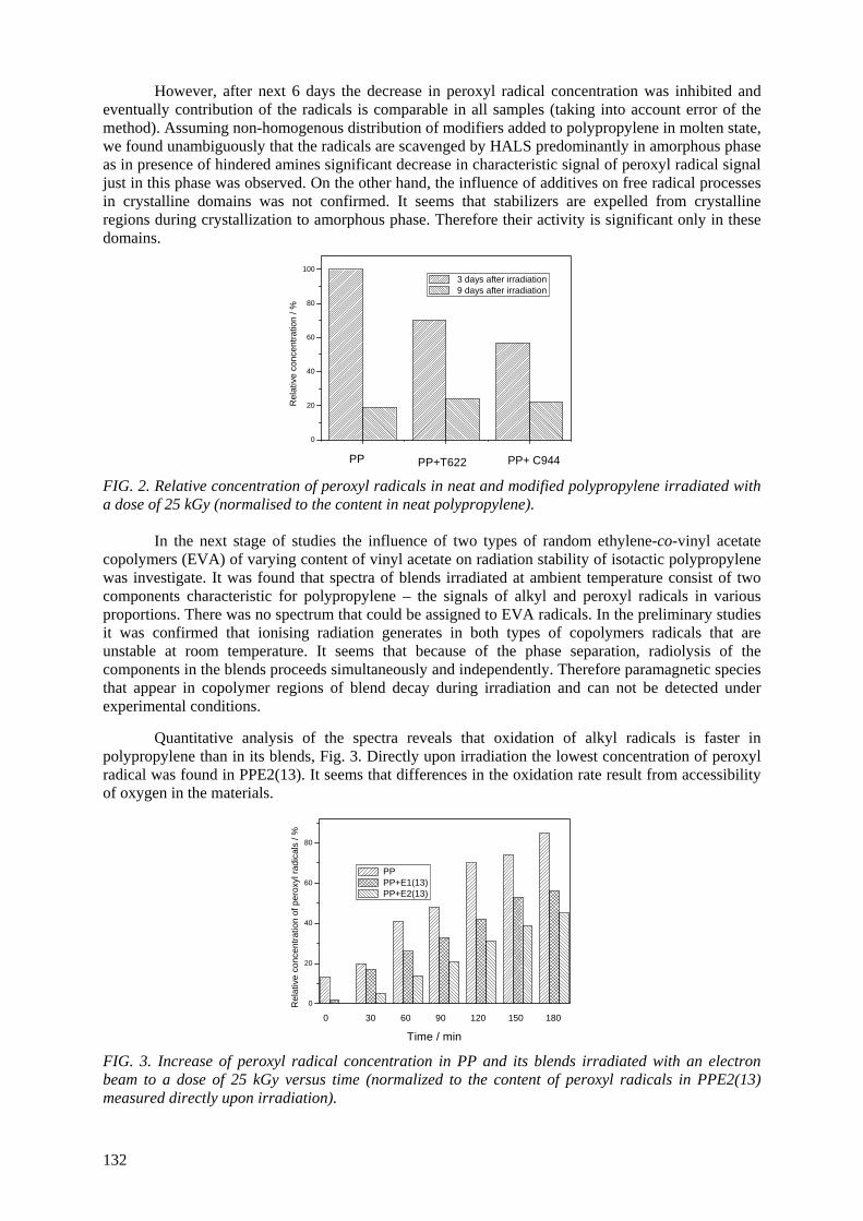
However, after next 6 days the decrease in peroxyl radical concentration was inhibited and eventually contribution of the radicals is comparable in all samples (taking into account error of the method). Assuming non-homogenous distribution of modifiers added to polypropylene in molten state, we found unambiguously that the radicals are scavenged by HALS predominantly in amorphous phase as in presence of hindered amines significant decrease in characteristic signal of peroxyl radical signal just in this phase was observed. On the other hand, the influence of additives on free radical processes in crystalline domains was not confirmed. It seems that stabilizers are expelled from crystalline regions during crystallization to amorphous phase. Therefore their activity is significant only in these domains.
0
20
40
60
80
100
Rel
ativ
e co
ncen
tratio
n / %
3 days after irradiation 9 days after irradiation
PP PP+T622 PP+ C944 FIG. 2. Relative concentration of peroxyl radicals in neat and modified polypropylene irradiated with a dose of 25 kGy (normalised to the content in neat polypropylene).
In the next stage of studies the influence of two types of random ethylene-co-vinyl acetate copolymers (EVA) of varying content of vinyl acetate on radiation stability of isotactic polypropylene was investigate. It was found that spectra of blends irradiated at ambient temperature consist of two components characteristic for polypropylene – the signals of alkyl and peroxyl radicals in various proportions. There was no spectrum that could be assigned to EVA radicals. In the preliminary studies it was confirmed that ionising radiation generates in both types of copolymers radicals that are unstable at room temperature. It seems that because of the phase separation, radiolysis of the components in the blends proceeds simultaneously and independently. Therefore paramagnetic species that appear in copolymer regions of blend decay during irradiation and can not be detected under experimental conditions.
Quantitative analysis of the spectra reveals that oxidation of alkyl radicals is faster in
polypropylene than in its blends, Fig. 3. Directly upon irradiation the lowest concentration of peroxyl radical was found in PPE2(13). It seems that differences in the oxidation rate result from accessibility of oxygen in the materials.
0
20
40
60
80
Rel
ativ
e co
ncen
tratio
n of
per
oxyl
radi
cals
/ %
PP PP+E1(13) PP+E2(13)
Time / min
0 30 60 90 120 150 180
FIG. 3. Increase of peroxyl radical concentration in PP and its blends irradiated with an electron beam to a dose of 25 kGy versus time (normalized to the content of peroxyl radicals in PPE2(13) measured directly upon irradiation).
132
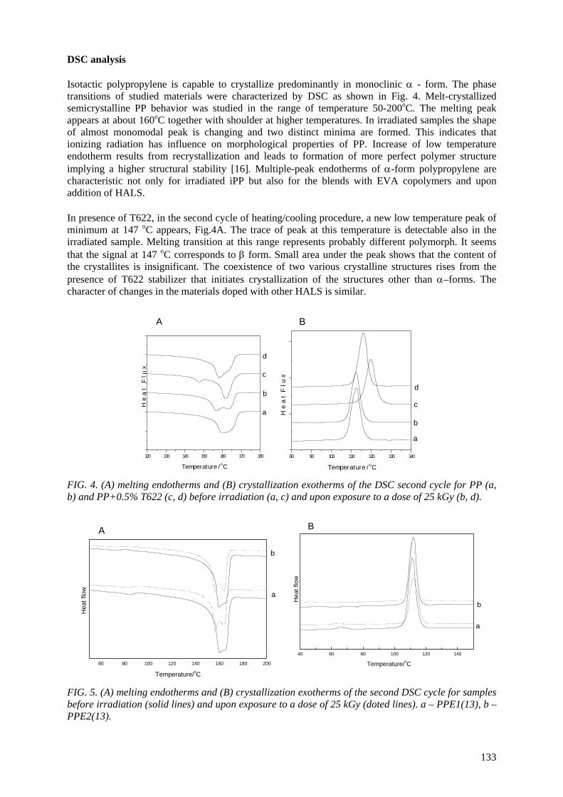
DSC analysis Isotactic polypropylene is capable to crystallize predominantly in monoclinic α - form. The phase transitions of studied materials were characterized by DSC as shown in Fig. 4. Melt-crystallized semicrystalline PP behavior was studied in the range of temperature 50-200oC. The melting peak appears at about 160oC together with shoulder at higher temperatures. In irradiated samples the shape of almost monomodal peak is changing and two distinct minima are formed. This indicates that ionizing radiation has influence on morphological properties of PP. Increase of low temperature endotherm results from recrystallization and leads to formation of more perfect polymer structure implying a higher structural stability [16]. Multiple-peak endotherms of α-form polypropylene are characteristic not only for irradiated iPP but also for the blends with EVA copolymers and upon addition of HALS.
In presence of T622, in the second cycle of heating/cooling procedure, a new low temperature peak of minimum at 147 oC appears, Fig.4A. The trace of peak at this temperature is detectable also in the irradiated sample. Melting transition at this range represents probably different polymorph. It seems that the signal at 147 oC corresponds to β form. Small area under the peak shows that the content of the crystallites is insignificant. The coexistence of two various crystalline structures rises from the presence of T622 stabilizer that initiates crystallization of the structures other than α–forms. The character of changes in the materials doped with other HALS is similar.
120 130 140 150 160 170 180
d
c
b
a
H e
a t
F l
u x
T e m p e r a t u r e / o C
A
80 90 100 110 120 130 140
d
c
b
a
H e
a t
F l
u x
T e m p e r a t u r e / o C
B
FIG. 4. (A) melting endotherms and (B) crystallization exotherms of the DSC second cycle for PP (a, b) and PP+0.5% T622 (c, d) before irradiation (a, c) and upon exposure to a dose of 25 kGy (b, d).
60 80 100 120 140 160 180 200
b
a
Hea
t flo
w
Temperature/oC
A
40 60 80 100 120 140
b
a
Hea
t flo
w
Temperature/oC
B
FIG. 5. (A) melting endotherms and (B) crystallization exotherms of the second DSC cycle for samples before irradiation (solid lines) and upon exposure to a dose of 25 kGy (doted lines). a – PPE1(13), b – PPE2(13).
133
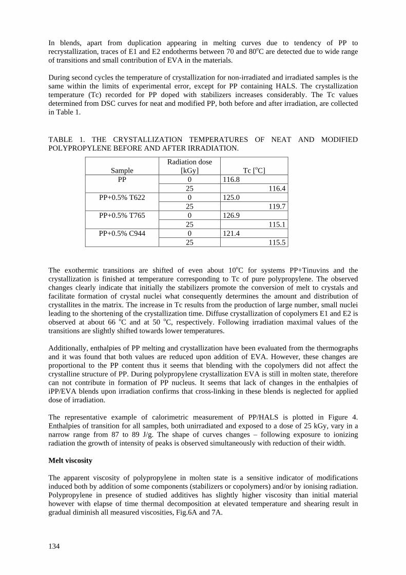
In blends, apart from duplication appearing in melting curves due to tendency of PP to recrystallization, traces of E1 and E2 endotherms between 70 and 80oC are detected due to wide range of transitions and small contribution of EVA in the materials. During second cycles the temperature of crystallization for non-irradiated and irradiated samples is the same within the limits of experimental error, except for PP containing HALS. The crystallization temperature (Tc) recorded for PP doped with stabilizers increases considerably. The Tc values determined from DSC curves for neat and modified PP, both before and after irradiation, are collected in Table 1. TABLE 1. THE CRYSTALLIZATION TEMPERATURES OF NEAT AND MODIFIED POLYPROPYLENE BEFORE AND AFTER IRRADIATION.
Sample
Radiation dose [kGy]
Tc [oC]
0 116.8 PP 25 116.40 125.0 PP+0.5% T622
25 119.70 126.9 PP+0.5% T765
25 115.10 121.4 PP+0.5% C944
25 115.5 The exothermic transitions are shifted of even about 10oC for systems PP+Tinuvins and the crystallization is finished at temperature corresponding to Tc of pure polypropylene. The observed changes clearly indicate that initially the stabilizers promote the conversion of melt to crystals and facilitate formation of crystal nuclei what consequently determines the amount and distribution of crystallites in the matrix. The increase in Tc results from the production of large number, small nuclei leading to the shortening of the crystallization time. Diffuse crystallization of copolymers E1 and E2 is observed at about 66 oC and at 50 oC, respectively. Following irradiation maximal values of the transitions are slightly shifted towards lower temperatures. Additionally, enthalpies of PP melting and crystallization have been evaluated from the thermographs and it was found that both values are reduced upon addition of EVA. However, these changes are proportional to the PP content thus it seems that blending with the copolymers did not affect the crystalline structure of PP. During polypropylene crystallization EVA is still in molten state, therefore can not contribute in formation of PP nucleus. It seems that lack of changes in the enthalpies of iPP/EVA blends upon irradiation confirms that cross-linking in these blends is neglected for applied dose of irradiation. The representative example of calorimetric measurement of PP/HALS is plotted in Figure 4. Enthalpies of transition for all samples, both unirradiated and exposed to a dose of 25 kGy, vary in a narrow range from 87 to 89 J/g. The shape of curves changes – following exposure to ionizing radiation the growth of intensity of peaks is observed simultaneously with reduction of their width. Melt viscosity The apparent viscosity of polypropylene in molten state is a sensitive indicator of modifications induced both by addition of some components (stabilizers or copolymers) and/or by ionising radiation. Polypropylene in presence of studied additives has slightly higher viscosity than initial material however with elapse of time thermal decomposition at elevated temperature and shearing result in gradual diminish all measured viscosities, Fig.6A and 7A.
134
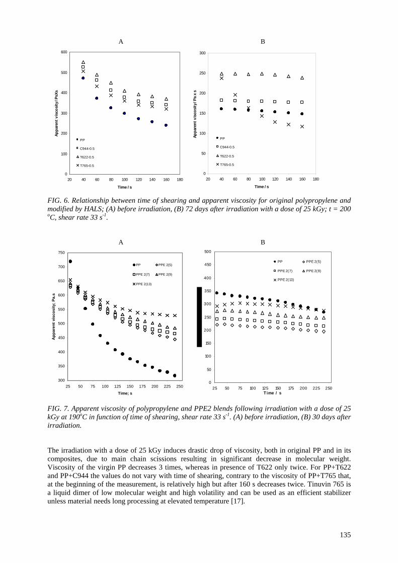
A B
0
100
200
300
400
500
600
20 40 60 80 100 120 140 160 180
Time / s
Appa
rent
vis
cosi
ty /
PsXs
PP
C944-0.5
T622-0.5
T765-0.5
0
50
100
150
200
250
300
20 40 60 80 100 120 140 160 180
Time / s
Appa
rent
vis
cosi
ty /
Pa x
s
PP
C944-0.5
T622-0.5
T765-0.5
FIG. 6. Relationship between time of shearing and apparent viscosity for original polypropylene and modified by HALS; (A) before irradiation, (B) 72 days after irradiation with a dose of 25 kGy; t = 200 oC, shear rate 33 s-1. A B
300
350
400
450
500
550
600
650
700
750
25 50 75 100 125 150 175 200 225 250
Time; s
App
aren
t vis
cosi
ty; P
a.s
PP PPE 2(5)
PPE 2(7) PPE 2(9)
PPE 2(13)
0
50
100
150
200
250
300
350
400
450
500
25 50 75 100 125 150 175 200 225 250T ime / s
PP PPE 2(5)
PPE 2(7) PPE 2(9)
PPE 2(13)
FIG. 7. Apparent viscosity of polypropylene and PPE2 blends following irradiation with a dose of 25 kGy at 190oC in function of time of shearing, shear rate 33 s-1. (A) before irradiation, (B) 30 days after irradiation.
The irradiation with a dose of 25 kGy induces drastic drop of viscosity, both in original PP and in its composites, due to main chain scissions resulting in significant decrease in molecular weight. Viscosity of the virgin PP decreases 3 times, whereas in presence of T622 only twice. For PP+T622 and PP+C944 the values do not vary with time of shearing, contrary to the viscosity of PP+T765 that, at the beginning of the measurement, is relatively high but after 160 s decreases twice. Tinuvin 765 is a liquid dimer of low molecular weight and high volatility and can be used as an efficient stabilizer unless material needs long processing at elevated temperature [17].
135
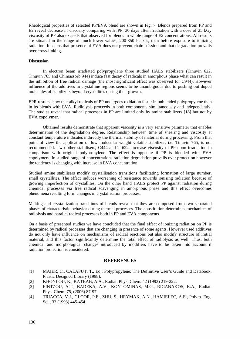
Rheological properties of selected PP/EVA blend are shown in Fig. 7. Blends prepared from PP and E2 reveal decrease in viscosity comparing with iPP. 30 days after irradiation with a dose of 25 kGy viscosity of PP also exceeds that observed for blends in whole range of E2 concentrations. All results are situated in the range of much lower values, 200-350 Pa x s, than before exposure to ionizing radiation. It seems that presence of EVA does not prevent chain scission and that degradation prevails over cross-linking. Discussion
In electron beam irradiated polypropylene three studied HALS stabilizers (Tinuvin 622, Tinuvin 765 and Chimassorb 944) induce fast decay of radicals in amorphous phase what can result in the inhibition of free radical damage (the most significant effect was observed for C944). However influence of the additives in crystalline regions seems to be unambiguous due to pushing out doped molecules of stabilizers beyond crystallites during their growth.
EPR results show that alkyl radicals of PP undergoes oxidation faster in unblended polypropylene than in its blends with EVA. Radiolysis proceeds in both components simultaneously and independently. The studies reveal that radical processes in PP are limited only by amine stabilizers [18] but not by EVA copolymer.
Obtained results demonstrate that apparent viscosity is a very sensitive parameter that enables determination of the degradation degree. Relationship between time of shearing and viscosity at constant temperature indicates indirectly the thermal stability of material during processing. From that point of view the application of low molecular weight volatile stabilizer, i.e. Tinuvin 765, is not recommended. Two other stabilisers, C444 and T 622, increase viscosity of PP upon irradiation in comparison with original polypropylene. The effect is opposite if PP is blended with EVA copolymers. In studied range of concentrations radiation degradation prevails over protection however the tendency is changing with increase in EVA concentration.
Studied amine stabilisers modify crystallisation transitions facilitating formation of large number, small crystallites. The effect induces worsening of resistance towards ionising radiation because of growing imperfection of crystallites. On the other hand HALS protect PP against radiation during chemical processes via free radical scavenging in amorphous phase and this effect overcomes phenomena resulting form changes in crystallisation processes. Melting and crystallization transitions of blends reveal that they are composed from two separated phases of characteristic behavior during thermal processes. The constitution determines mechanism of radiolysis and parallel radical processes both in PP and EVA components. On a basis of presented studies we have concluded that the final effect of ionizing radiation on PP is determined by radical processes that are changing in presence of some agents. However used additives do not only have influence on mechanisms of radical reactions but also modify structure of initial material, and this factor significantly determine the total effect of radiolysis as well. Thus, both chemical and morphological changes introduced by modifiers have to be taken into account if radiation protection is considered.
REFERENCES
[1] MAIER, C., CALAFUT, T., Ed.; Polypropylene: The Definitive User’s Guide and Databook, Plastic Designed Library (1998).
[2] KHOYLOU, K., KATBAB, A.A., Radiat. Phys. Chem. 42 (1993) 219-222. [3] FINTZOU, A.T., BADEKA, A.V., KONTOMINAS, M.G., RIGANAKOS, K.A., Radiat.
Phys. Chem. 75, (2006) 87-97. [4] TRIACCA, V.J., GLOOR, P.E., ZHU, S., HRYMAK, A.N., HAMIELEC, A.E., Polym. Eng.
Sci., 33 (1993) 445-454.
136
[5] GENSHUAN, W., JINLIANG, Q., XUANG, H., FENGRU, Z., JILAN, W., Radiat. Phys. Chem. 52 (1998) 237-241.
[6] AYMES-CHODUR, C., BETZ, N., LEGENDRE, B., YAGOUBI, N., Polym. Degrad. Stab. 91 (2006) 649-662.
[7] BOERSMA, A., Polym. Degrad. Stab. 91 (2006) 472-478. [8] MIHAILOVA, M., KRESTEVA, M., AIVAZOVA, N., KRESTEV, V., NEDKOV, E., Radiat.
Phys. Chem. 56 (1999) 581-589. [9] RAMIREZ-VARGAS, E., NAVARRO-RODRIGUEZ, D., BLANQUETO-MENCHACA ,
A.I., HUERTA-MARTINEZ, B.M., PALACIOS-MEZTA, M., Polym. Degrad. Stab. 86 (2004) 301-307.
[10] CARLSSON, D.J., CAN, Z., WILES, D.M., J. App. Polym. Sci., 33 (1987) 875-884. [11] WANG, H., CHEN, W., J. App. Polym. Sci. 69 (1998) 2649-2656. [12] GENSLER, R., PLUMMER, C.J.G., KAUSCH, H.-H., KRAMER, E., PAUQUET, J.-R.,
ZWEIFEL, H., Polym. Degrad. Stab. 67 (2000) 195-208. [13] ZAHARESCU, T., CHIPARA, M., POSTOLACHE, M., Polym. Degrad. Stab., 66, 5-8, 1999. [14] KOSTOSKI, D., BABIC, D., STOJANOVIC, Z., GAL, O., Radiat. Phys. Chem. 28, (1986)
269-272. [15] KASHIWABARA, H., SHIMADA, S., HORI, Y., Radiat. Phys. Chem. 37 (1991) 511-515. [16] MENYHARD, A., VARGA, J., LIBER, A., BELINA G., Eur. Polym. J. 41 (2005) 669-667. [17] SUN, G.J., JANG, H.J., KAANG, S., CHAE, K.H., Polymer, 43 (2002) 5855-5863. [18] PRZYBYTNIAK, G., MIRKOWSKI, K., RAFALSKI, A., NOWICKI, A., LEGOCKA, I.,
ZIMEK, Z., Nukleonika 50 (2005) 153-159.
137

IMPROVEMENT IN THE THERMAL PERFORMANCE OF POLYPROPYLENE
T. ZAHARESCU National Institute for Electrical Engineering Bucharest, Romania
Abstract
In the framework of the CRP our contribution consists of the two directions of investigation on the stabilization of polypropylene: one way follows the compatibilization of the blends of polypropylene with ethylene-propylene terpolymer in the presence of divinylbenzene, and the second way is represented by the nanocomposites polypropylene/calcium carbonate. The irradiation of ethylene-propylene diene terpolymer/polypropylene blends in the presence of divinylbenzene is an alternative procedure, which improves material lifetime and may be applied to material recycling. The selection of these systems is justified on the basis of their capacity on the providing free radicals. The two polymer components, EPDM and PP, can be degraded with various rates because of the different contents of methyl groups. The polymer samples consisted of both materials under various ratios (20:80, 40:60, 60:40 and 80:20); individual materials were also subjected to the action of (137Cs) γ-rays. Divinylbenzene, a hydrocarbon which plays the role of radical source was added iat the level of 5% (w/w). The stabilization effect was tested by two methods: oxygen uptake and IR spectroscopy at the characteristic bands (1720 cm-1 and 3350 cm-1) for carbonyl and hydroxyl groups, respectively. The γ-exposure induced a slower oxidative degradation in the presence of DVB. The carbonyl and hydroxyl indexes were calculated for all formulations. From oxidability investigation the kinetic parameters for thermal oxidation of irradiated samples were calculated. Their modification depicts the radiochemical stability, which is an important feature in the long term applications. The ability of divinylbenzene in the radiation stabilization of studied polyolefin blends is discussed in relation with the modification of exposure dose and sample composition. The irradiation performed in air represents a proper test for the qualification of this polymeric system. Thermal and γ radiation stability of iPP containing CaCO3 nanoparticles were investigated by oxygen uptake procedure at 160°C. The loading of iPP matrix was maximum 25% (w/w). The behaviour on thermal oxidation was investigated for two formulations of iPP compounds differing by the surface characteristics of nanoparticles (i.e. uncoated and stearic acid-coated filler). Three irradiation doses (5, 15 and 25 kGy) were applied. The efficient protection of stabilizers that are present in the as-prepared formulations was emphasized by proper values of the kinetic parameters obtained for oxidation. The contribution of CaCO3 nanoparticles to the oxidative process of iPP is discussed.
1. OBJECTIVE OF THE RESEARCH
The necessity of recovery for the large amounts of wastes by alternative procedures focuses the activity on the application of radiation processing on the reclaim of polypropylene and the commission of new products. The study includes two differrent options for the improvement in the thermal strength of polypropylene-based items.
2. INTRODUCTION
The fundamental process of polymer degradation and stabilization has been expensively studied[1-3].
The radiation ageing of polymers offers the advantage of fast material qualification, which involves the resistance of material to the action of various stressors. The interest in this kind of studies reveals the practical side of the usage of polymers, which cover the most areas of human activities. There were reported several results on this topic, because the qualification of materials represents the guarantee of the long term work of equipments.
The stabilization of polymers is a good procedure to preserve constant properties for longer period. For nuclear application, the most important feature is the radiation resistance in order to confer low frequency of maintenance activity. The stabilization ability of antioxidants is usually related by the substitution of a proton in the molecule of additive. The most used antioxidants belong to the classes of hindered phenols and hindered amines. In the most of cases the do not play the role of antirad stabilizers, but they act as efficient in the thermal oxidation. However, there were reported
139
certain systems, where the studied antioxidant presents a satisfactory efficiency in the radiation field[4-
14]. However, certain simple hydrocarbons are able to promote stabilization of polymer by crosslinking.
The radiochemical stability of each polymeric component of studied blends have been previously studied.[5,6,8,9,15,16] Polypropylene is fast degraded in air and becomes the reactive phase that determines the progress of oxidation. As it has been previously stated[17,18], polypropylene provides the most proportion of radicals that initiate oxidation. The mechanisms that are followed by the two components during oxidation were presented in other papers[8,19,20]. The presence of additive delays the start of oxidation, as it was reported by Chodak et al[21]. The alteration of divinylbenzene due to the direct action of incidental radiation can be involved, because this compound presents high radiation reactivity determined by scission of double bond from vinyl group[22].
A large number of studies on the preparation and characterization of polymer/nanoparticles matrix were reported,[23-32] because of their excellent functional properties. The presence of nanoscale inorganic fillers improves mechanical, thermal and gas barrier characteristics.[33-37] Several promising formulations of polymer hybrids were proposed for satisfying various requirements for a large number of applications. However, the problem of thermal stability of polymer composites is of a great interest being directly related to the material durability. The topic of thermal degradation has received a special attention due to the strong influence of the service conditions on the behavior of composites. The characterization of material depreciation by heat provides useful information for storage, processing and long-term use, namely the life of products. Ever using well-elaborated technologies of preparation, the stress factors act on any time. Recent papers have emphasized the phenomenological analysis of degradation in connection with various testing methods. The most applied procedures for depicting the thermal behavior of polymer composites were DSC and TGA. These papers have reported the difference between unloaded and polymer composites, which is caused by the modification in surface energy between the microphases, which exist in the tested material.
For inducing a high rate and advanced degradation, ionizing radiation may be used. Data obtained from accelerated ageing testing prove the capacity of material to resist for a certain period to the action of vigorous energetic agents. The durability of any material under high energy radiation exposure depends on many features through which the chemical nature of basic material and the sample formulation determine the kinetic behavior during degradation.[38-40]
Effects of irradiation on polypropylene have been extensively studied. The most of them have emphasized the degradation of this polyolefin under radiochemical processing[38,41-46] or its crosslinking in the presence of suitable additional monomer.[41,47,48] Other assays on radiation resistance of polypropylene have reported the effects of stabilization additives (antioxidants), which delay the start of oxidation and mitigate the rate of destruction.[49-52] The radiolysis of polymer substrate causes the free radical formation, which is followed by oxidation reactions. The rate of oxygen consumption and the absorbent properties of calcium carbonate nanoparticles seem to influence the state of degradation of irradiated polypropylene.
The goal of this works is the achievement of significant performances of PP composites in order to apply these procedures to improve the quality of polypropylene wastes. This work combines the contribution of polymeric compounds and divinylbenzene with nanocomposite materials to the increase in the thermal stability of studied systems.
3. MATERIALS AND METHODS
3.1. Materials
3.1.1. Ethylene-propylene diene elastomer
This polymer was provided by ARPECHIM Piteşti (Romania) as Terpit C®. Its main characteristics are presented in Table 1.
140
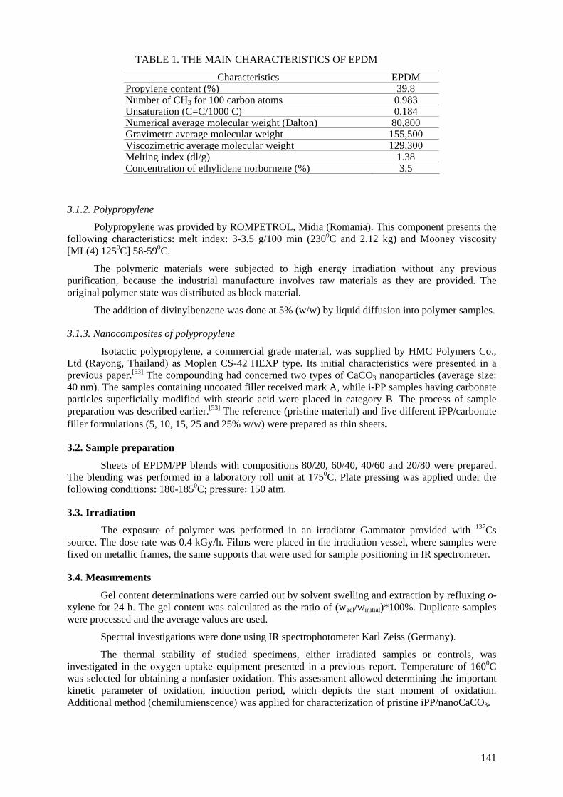
TABLE 1. THE MAIN CHARACTERISTICS OF EPDM
Characteristics EPDM Propylene content (%) 39.8 Number of CH3 for 100 carbon atoms 0.983 Unsaturation (C=C/1000 C) 0.184 Numerical average molecular weight (Dalton) 80,800 Gravimetrc average molecular weight 155,500 Viscozimetric average molecular weight 129,300 Melting index (dl/g) 1.38 Concentration of ethylidene norbornene (%) 3.5
3.1.2. Polypropylene
Polypropylene was provided by ROMPETROL, Midia (Romania). This component presents the following characteristics: melt index: 3-3.5 g/100 min (2300C and 2.12 kg) and Mooney viscosity [ML(4) 1250C] 58-590C.
The polymeric materials were subjected to high energy irradiation without any previous purification, because the industrial manufacture involves raw materials as they are provided. The original polymer state was distributed as block material.
The addition of divinylbenzene was done at 5% (w/w) by liquid diffusion into polymer samples.
3.1.3. Nanocomposites of polypropylene
Isotactic polypropylene, a commercial grade material, was supplied by HMC Polymers Co., Ltd (Rayong, Thailand) as Moplen CS-42 HEXP type. Its initial characteristics were presented in a previous paper.[53] The compounding had concerned two types of CaCO3 nanoparticles (average size: 40 nm). The samples containing uncoated filler received mark A, while i-PP samples having carbonate particles superficially modified with stearic acid were placed in category B. The process of sample preparation was described earlier.[53] The reference (pristine material) and five different iPP/carbonate filler formulations (5, 10, 15, 25 and 25% w/w) were prepared as thin sheets.
3.2. Sample preparation
Sheets of EPDM/PP blends with compositions 80/20, 60/40, 40/60 and 20/80 were prepared. The blending was performed in a laboratory roll unit at 1750C. Plate pressing was applied under the following conditions: 180-1850C; pressure: 150 atm.
3.3. Irradiation
The exposure of polymer was performed in an irradiator Gammator provided with 137Cs source. The dose rate was 0.4 kGy/h. Films were placed in the irradiation vessel, where samples were fixed on metallic frames, the same supports that were used for sample positioning in IR spectrometer.
3.4. Measurements
Gel content determinations were carried out by solvent swelling and extraction by refluxing o-xylene for 24 h. The gel content was calculated as the ratio of (wgel/winitial)*100%. Duplicate samples were processed and the average values are used.
Spectral investigations were done using IR spectrophotometer Karl Zeiss (Germany).
The thermal stability of studied specimens, either irradiated samples or controls, was investigated in the oxygen uptake equipment presented in a previous report. Temperature of 1600C was selected for obtaining a nonfaster oxidation. This assessment allowed determining the important kinetic parameter of oxidation, induction period, which depicts the start moment of oxidation. Additional method (chemilumienscence) was applied for characterization of pristine iPP/nanoCaCO3.
141
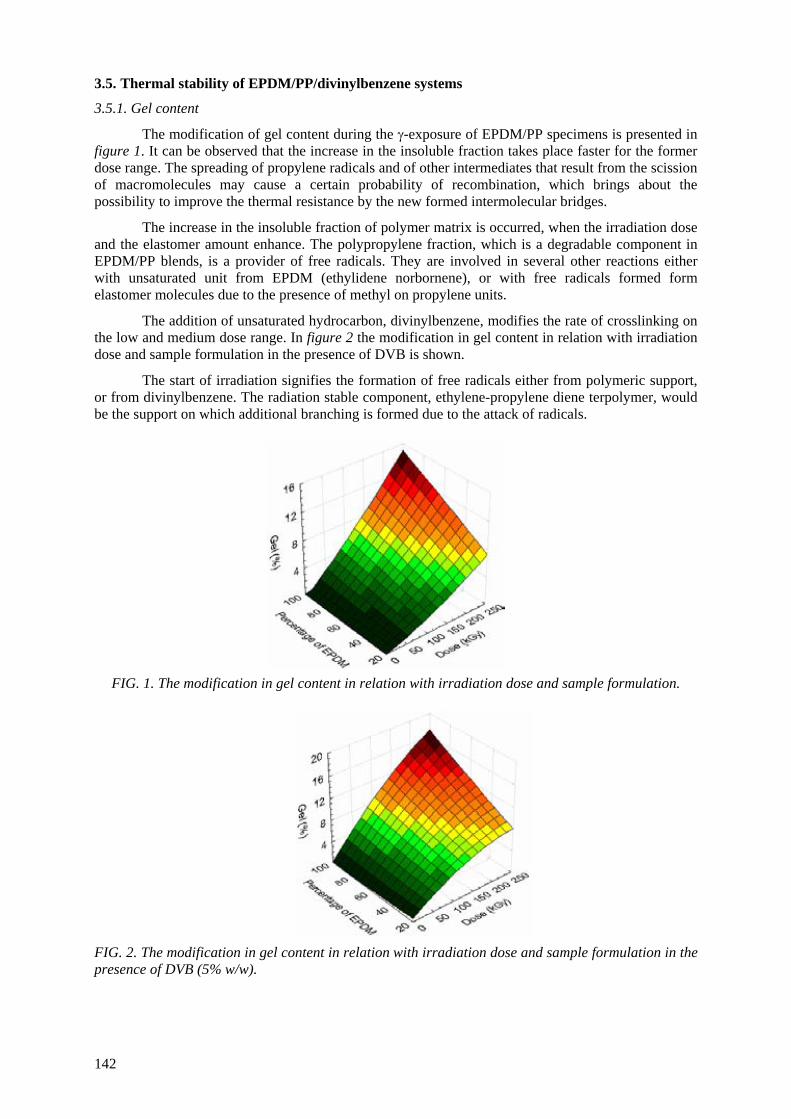
3.5. Thermal stability of EPDM/PP/divinylbenzene systems
3.5.1. Gel content
The modification of gel content during the γ-exposure of EPDM/PP specimens is presented in figure 1. It can be observed that the increase in the insoluble fraction takes place faster for the former dose range. The spreading of propylene radicals and of other intermediates that result from the scission of macromolecules may cause a certain probability of recombination, which brings about the possibility to improve the thermal resistance by the new formed intermolecular bridges.
The increase in the insoluble fraction of polymer matrix is occurred, when the irradiation dose and the elastomer amount enhance. The polypropylene fraction, which is a degradable component in EPDM/PP blends, is a provider of free radicals. They are involved in several other reactions either with unsaturated unit from EPDM (ethylidene norbornene), or with free radicals formed form elastomer molecules due to the presence of methyl on propylene units.
The addition of unsaturated hydrocarbon, divinylbenzene, modifies the rate of crosslinking on the low and medium dose range. In figure 2 the modification in gel content in relation with irradiation dose and sample formulation in the presence of DVB is shown.
The start of irradiation signifies the formation of free radicals either from polymeric support, or from divinylbenzene. The radiation stable component, ethylene-propylene diene terpolymer, would be the support on which additional branching is formed due to the attack of radicals.
FIG. 1. The modification in gel content in relation with irradiation dose and sample formulation. FIG. 2. The modification in gel content in relation with irradiation dose and sample formulation in the presence of DVB (5% w/w).
142
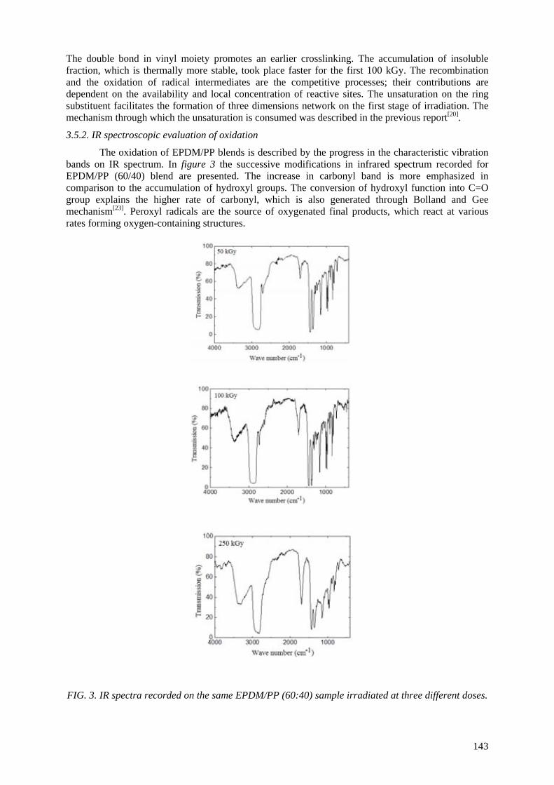
The double bond in vinyl moiety promotes an earlier crosslinking. The accumulation of insoluble fraction, which is thermally more stable, took place faster for the first 100 kGy. The recombination and the oxidation of radical intermediates are the competitive processes; their contributions are dependent on the availability and local concentration of reactive sites. The unsaturation on the ring substituent facilitates the formation of three dimensions network on the first stage of irradiation. The mechanism through which the unsaturation is consumed was described in the previous report[20].
3.5.2. IR spectroscopic evaluation of oxidation
The oxidation of EPDM/PP blends is described by the progress in the characteristic vibration bands on IR spectrum. In figure 3 the successive modifications in infrared spectrum recorded for EPDM/PP (60/40) blend are presented. The increase in carbonyl band is more emphasized in comparison to the accumulation of hydroxyl groups. The conversion of hydroxyl function into C=O group explains the higher rate of carbonyl, which is also generated through Bolland and Gee mechanism[23]. Peroxyl radicals are the source of oxygenated final products, which react at various rates forming oxygen-containing structures.
FIG. 3. IR spectra recorded on the same EPDM/PP (60:40) sample irradiated at three different doses.
143
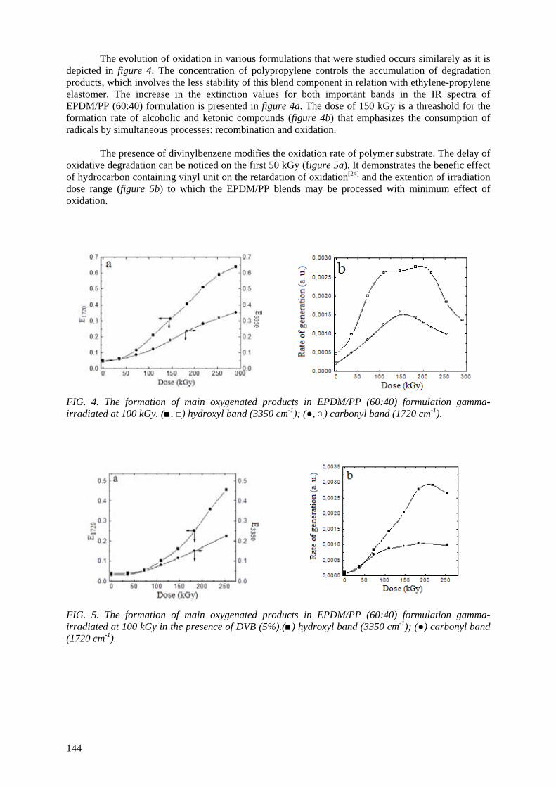
144
The evolution of oxidation in various formulations that were studied occurs similarely as it is depicted in figure 4. The concentration of polypropylene controls the accumulation of degradation products, which involves the less stability of this blend component in relation with ethylene-propylene elastomer. The increase in the extinction values for both important bands in the IR spectra of EPDM/PP (60:40) formulation is presented in figure 4a. The dose of 150 kGy is a threashold for the formation rate of alcoholic and ketonic compounds (figure 4b) that emphasizes the consumption of radicals by simultaneous processes: recombination and oxidation. The presence of divinylbenzene modifies the oxidation rate of polymer substrate. The delay of oxidative degradation can be noticed on the first 50 kGy (figure 5a). It demonstrates the benefic effect of hydrocarbon containing vinyl unit on the retardation of oxidation[24] and the extention of irradiation dose range (figure 5b) to which the EPDM/PP blends may be processed with minimum effect of oxidation. FIG. 4. The formation of main oxygenated products in EPDM/PP (60:40) formulation gamma- irradiated at 100 kGy. (■, □) hydroxyl band (3350 cm-1); (●, ○) carbonyl band (1720 cm-1). FIG. 5. The formation of main oxygenated products in EPDM/PP (60:40) formulation gamma- irradiated at 100 kGy in the presence of DVB (5%).(■) hydroxyl band (3350 cm-1); (●) carbonyl band (1720 cm-1).
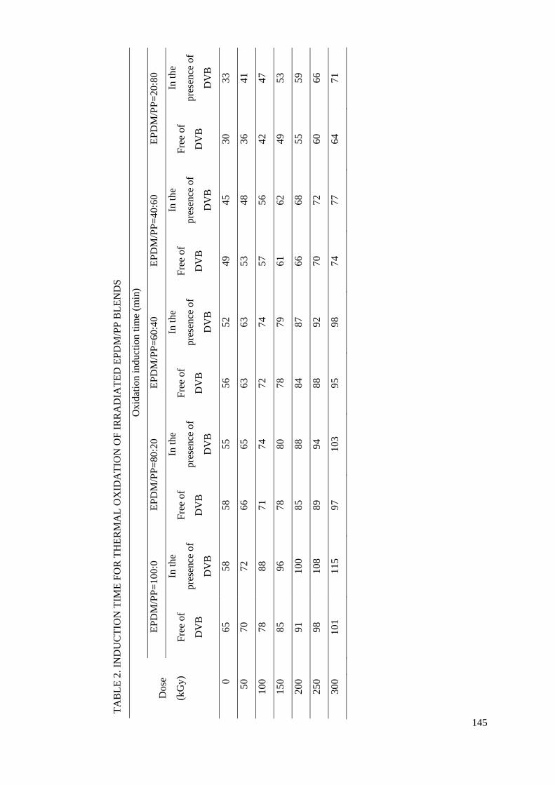
TAB
LE 2
. IN
DU
CTI
ON
TIM
E FO
R T
HER
MA
L O
XID
ATI
ON
OF
IRR
AD
IATE
D E
PDM
/PP
BLE
ND
S
Oxi
datio
n in
duct
ion
time
(min
)
EPD
M/P
P=10
0:0
EPD
M/P
P=80
:20
EPD
M/P
P=60
:40
EPD
M/P
P=40
:60
EPD
M/P
P=20
:80
Dos
e
(kG
y)
Free
of
DV
B
In th
e
pres
ence
of
DV
B
Free
of
DV
B
In th
e
pres
ence
of
DV
B
Free
of
DV
B
In th
e
pres
ence
of
DV
B
Free
of
DV
B
In th
e
pres
ence
of
DV
B
Free
of
DV
B
In th
e
pres
ence
of
DV
B
0
65
58
58
55
56
52
49
45
30
33
50
70
72
66
65
63
63
53
48
36
41
100
78
88
71
74
72
74
57
56
42
47
150
85
96
78
80
78
79
61
62
49
53
200
91
10
0 85
88
84
87
66
68
55
59
250
98
10
8 89
94
88
92
70
72
60
66
300
10
1 11
5 97
10
3 95
98
74
77
64
71
145
3.5.3. Oxygen uptake determinations
The different PP proportions in the studied systems determine various rates of oxidation. Because of the low stability of polypropylene under the action of high energy radiation, the changes in the oxidation induction period (Table 2) reflect the contributions to crosslinking of polymer materials and hydrocarbon the last being involved in the radiochemical modification of substrate. The promotion of higher thermal stability by DVB is tightly correlated to the competition between oxidation and recombination of free radicals. Some remarks must be metioned:
• divinylbenzene induces a certain level of oxidation in the unirradiated samples; • the exposure to γ-rays increases the thermal stability of radiochemically treated EPDM/PP
blends; • the irradiation brings about an improvement of oxidation induction time even in the case of
the formulation containing 80 % PP. This kinetic parameter determined for elastomer sample has comparable value for EPDM/PP (20:80) at 250-300 kGy;
• the thermal stability of radiation exposed studied polyolefin blends (modified with DVB) becomes an important characteristic for the ware-products manufacture;
• the recovery of polypropylene as EPDM/PP blends by radiochemical procedure is a good alternative, if divinylbenzene is present as a crosskinking agent;
• the thermal resistance of EPDM/PP blends is ameliorated by the presence of DVB due to its reactivity to break double bond from vinyl group and the possibility of crosslinking propagation by radical mechanism.
3.6. Thermal stability of polypropylene nanocomposites
Radiation processing of polymers is a useful tool for the check of material resistance under hard service conditions and provides a conclusive picture on the manner through which the material follows standard recommendations. For composite, the accelerated tests offer suitable conclusions concerning the effects of additives and fillers on the long term usage. Ionizing radiation causes the split of weaker bonds. Polypropylene is subjected to radiation degradation due to the presence of tertiary carbons in macromolecule backbone. Oxygen which preexists in virgin material or is diffused into polymer bulk during irradiation promotes oxidation by reactions with free radicals. Final radiolysis products will be spread in the polymer mass in correlation with material crystallinity and the size of molecules. In the case of nanocomposites, the filler particles influence the progress of oxidation.
Calcium carbonate nanoparticles modify the behavior of basic material because of their large specific surface and the homogenous dispersion in polymer. The decrease in mechanical properties was reported earlier53 but it would be accompanied by the change in thermal stability. In the case of coated particles, it would be expected that the covering film will influence the progress of oxidation.
Isotactic polypropylene filled with calcium carbonate nanoparticles presents slight differences in the values of oxidation induction time, while the propagation of oxidation looks somewhat unlike (figure 6). The initial amount of dissolved oxygen is about the same for all samples, but, the O2 diffusion into polymer during uptake measurements depends on the filler consistency. The higher the concentration of nanoparticles, the faster the oxidation degradation (Tables III and IV), namely, the thermal stability is determined by the homogeneity spreading of carbonate particles in polymer.
The exposure of i-PP samples to γ radiation brings about the decrease in the both kinetic parameters: oxidation induction time and oxidation rate. The nature of degradation environment determines different values of kinetic parameters for the advance in oxidation. In figure 7 the dependencies of consumed oxygen on time is presented for samples containing coated CaCO3 nanoparticles, which were irradiated at 25 kGy in the both oxidative media.
146
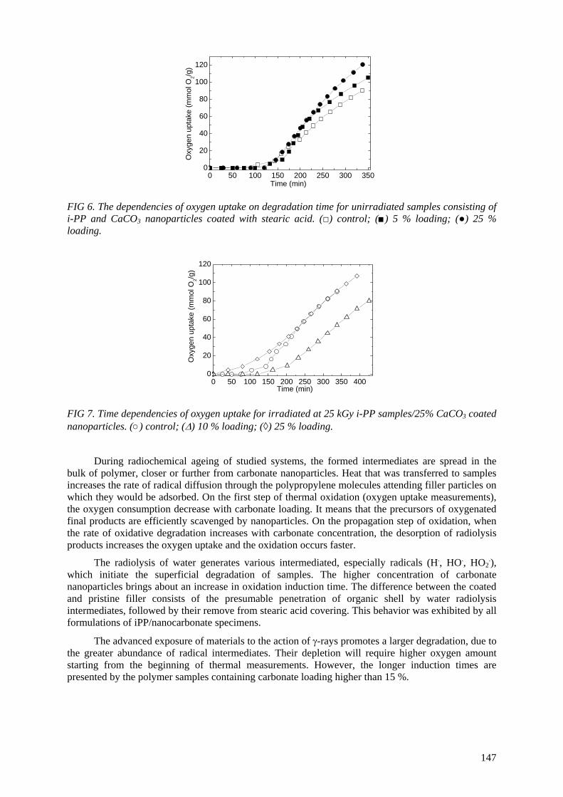
147
0 50 100 150 200 250 300 3500
20
40
60
80
100
120
The advanced exposure of materials to the action of γ-rays promotes a larger degradation, due to the greater abundance of radical intermediates. Their depletion will require higher oxygen amount starting from the beginning of thermal measurements. However, the longer induction times are presented by the polymer samples containing carbonate loading higher than 15 %.
During radiochemical ageing of studied systems, the formed intermediates are spread in the bulk of polymer, closer or further from carbonate nanoparticles. Heat that was transferred to samples increases the rate of radical diffusion through the polypropylene molecules attending filler particles on which they would be adsorbed. On the first step of thermal oxidation (oxygen uptake measurements), the oxygen consumption decrease with carbonate loading. It means that the precursors of oxygenated final products are efficiently scavenged by nanoparticles. On the propagation step of oxidation, when the rate of oxidative degradation increases with carbonate concentration, the desorption of radiolysis products increases the oxygen uptake and the oxidation occurs faster.
Oxy
gen
upta
ke (m
mol
O2/g
)Time (min)
0 50 100 150 200 250 300 350 4000
20
40
60
80
100
120
FIG 6. The dependencies of oxygen uptake on degradation time for unirradiated samples consisting of i-PP and CaCO3 nanoparticles coated with stearic acid. (□) control; (■) 5 % loading; (●) 25 % loading.
The radiolysis of water generates various intermediated, especially radicals (H., HO., HO2.),
which initiate the superficial degradation of samples. The higher concentration of carbonate nanoparticles brings about an increase in oxidation induction time. The difference between the coated and pristine filler consists of the presumable penetration of organic shell by water radiolysis intermediates, followed by their remove from stearic acid covering. This behavior was exhibited by all formulations of iPP/nanocarbonate specimens.
FIG 7. Time dependencies of oxygen uptake for irradiated at 25 kGy i-PP samples/25% CaCO3 coated nanoparticles. (○) control; (Δ) 10 % loading; (◊) 25 % loading.
Oxy
gen
upta
ke (m
mol
O2/g
)
Time (min)
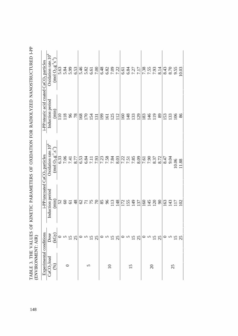
TAB
LE 3
. TH
E V
ALU
ES O
F K
INET
IC P
AR
AM
ETER
S O
F O
XID
ATI
ON
FO
R R
AD
IOLY
ZED
NA
NO
STR
UC
TUR
ED I
-PP
(EN
VIR
ON
MEN
T: A
IR)
Expe
rimen
tal c
ondi
tions
i-PP/
unco
ated
CaC
O3 p
artic
les
i-P
P/st
earic
aci
d co
ated
CaC
O3 p
artic
les
CaC
O3 lo
ad
(%)
D
ose
(kG
y)
In
duct
ion
perio
d (m
in)
O
xida
tion
rate
.104
(mol
O2.g
-1.s-1
)
Indu
ctio
n pe
riod
(min
)
Oxi
datio
n ra
te.1
04 (m
ol O
2.g-1
s-1)
0
52
6.33
110
5.
63
5
60
7.
06
11
8
5.84
15
61
7.41
96
5.99
0
25
48
8.
77
78
6.
53
0
62
6.
53
16
8
5.46
5
71
6.84
170
5.
82
15
75
7.
11
15
4
6.61
5
25
70
7.
93
13
1
7.00
0
85
7.23
199
6.
48
5
96
7.
58
16
1
6.82
15
113
7.
84
12
5
7.09
10
25
14
8
8.03
112
7.
22
0
17
2
7.22
160
6.
61
5
15
5
7.51
148
6.
84
15
14
9
7.85
133
7.
27
15
25
13
7
8.09
129
7.
17
0
16
0
7.61
183
7.
38
5
14
5
7.90
146
7.
55
15
12
0
8.37
119
7.
93
20
25
90
8.
72
89
8.
14
0
16
3
8.47
153
8.
43
5
14
3
9.04
133
8.
70
15
11
7
10.
06
10
6
9.55
25
25
10
2
11.
88
86
10
.03
148
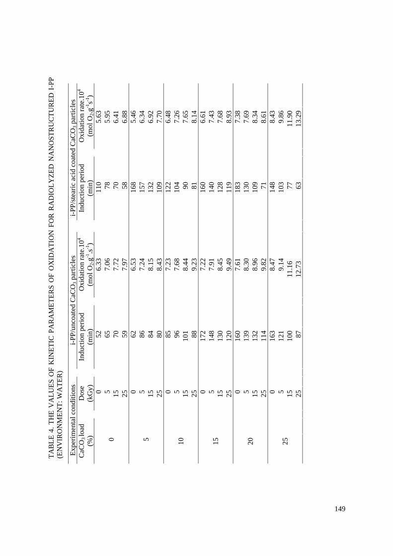
TAB
LE 4
. TH
E V
ALU
ES O
F K
INET
IC P
AR
AM
ETER
S O
F O
XID
ATI
ON
FO
R R
AD
IOLY
ZED
NA
NO
STR
UC
TUR
ED I
-PP
(EN
VIR
ON
MEN
T: W
ATE
R)
Expe
rimen
tal c
ondi
tions
i-PP/
unco
ated
CaC
O3 p
artic
les
i-P
P/st
earic
aci
d co
ated
CaC
O3 p
artic
les
CaC
O3 lo
ad
(%)
D
ose
(kG
y)
In
duct
ion
perio
d (m
in)
O
xida
tion
rate
.104
(mol
O2.g
-1.s-1
)
Indu
ctio
n pe
riod
(min
)
Oxi
datio
n ra
te.1
04 (m
ol O
2.g-1
s-1)
0
52
6.33
110
5.
63
5
65
7.
06
78
5.
95
15
70
7.
72
70
6.
41
0
25
59
7.
97
58
6.
88
0
62
6.
53
16
8
5.46
5
86
7.24
157
6.
34
15
84
8.
15
13
2
6.92
5
25
80
8.
43
10
9
7.70
0
85
7.23
122
6.
48
5
96
7.
68
10
4
7.26
15
101
8.
44
90
7.
65
10
25
88
9.
23
81
8.
14
0
17
2
7.22
160
6.
61
5
14
8
7.91
140
7.
43
15
13
0
8.45
128
7.
68
15
25
12
0
9.49
119
8.
93
0
16
0
7.61
183
7.
38
5
13
9
8.30
130
7.
69
15
13
2
8.96
109
8.
34
20
25
11
4
9.82
71
8.61
0
163
8.
47
14
8
8.43
5
121
9.
14
10
3
9.86
15
100
11.1
6
77
11.9
0
25
25
87
12.7
3
63
13.2
9
149
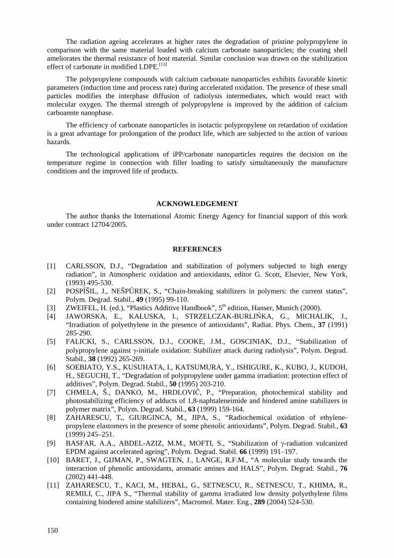
The radiation ageing accelerates at higher rates the degradation of pristine polypropylene in comparison with the same material loaded with calcium carbonate nanoparticles; the coating shell ameliorates the thermal resistance of host material. Similar conclusion was drawn on the stabilization effect of carbonate in modified LDPE.[13]
The polypropylene compounds with calcium carbonate nanoparticles exhibits favorable kinetic parameters (induction time and process rate) during accelerated oxidation. The presence of these small particles modifies the interphase diffusion of radiolysis intermediates, which would react with molecular oxygen. The thermal strength of polypropylene is improved by the addition of calcium carboannte nanophase.
The efficiency of carbonate nanoparticles in isotactic polypropylene on retardation of oxidation is a great advantage for prolongation of the product life, which are subjected to the action of various hazards.
The technological applications of iPP/carbonate nanoparticles requires the decision on the temperature regime in connection with filler loading to satisfy simultaneously the manufacture conditions and the improved life of products.
ACKNOWLEDGEMENT
The author thanks the International Atomic Energy Agency for financial support of this work under contract 12704/2005.
REFERENCES
[1] CARLSSON, D.J., “Degradation and stabilization of polymers subjected to high energy radiation”, in Atmospheric oxidation and antioxidants, editor G. Scott, Elsevier, New York, (1993) 495-530.
[2] POSPÍŠIL, J., NEŠPŮREK, S., “Chain-breaking stabilizers in polymers: the current status”, Polym. Degrad. Stabil., 49 (1995) 99-110.
[3] ZWEIFEL, H. (ed.), “Plastics Additive Handbook”, 5th edition, Hanser, Munich (2000). [4] JAWORSKA, E., KAŁUSKA, I., STRZELCZAK-BURLIŃKA, G., MICHALIK, J.,
“Irradiation of polyethylene in the presence of antioxidants”, Radiat. Phys. Chem., 37 (1991) 285-290.
[5] FALICKI, S., CARLSSON, D.J., COOKE, J.M., GOSCINIAK, D.J., “Stabilization of polypropylene against γ-initiale oxidation: Stabilizer attack during radiolysis”, Polym. Degrad. Stabil., 38 (1992) 265-269.
[6] SOEBIATO, Y.S., KUSUHATA, I., KATSUMURA, Y., ISHIGURE, K., KUBO, J., KUDOH, H., SEGUCHI, T., “Degradation of polypropylene under gamma irradiation: protection effect of additives”, Polym. Degrad. Stabil., 50 (1995) 203-210.
[7] CHMELA, Š., DANKO, M., HRDLOVIČ, P., “Preparation, photochemical stability and photostabilizing efficiency of adducts of 1,8-naphtaleneimide and hindered amine stabilizers in polymer matrix”, Polym. Degrad. Stabil., 63 (1999) 159-164.
[8] ZAHARESCU, T., GIURGINCA, M., JIPA, S., “Radiochemical oxidation of ethylene-propylene elastomers in the presence of some phenolic antioxidants”, Polym. Degrad. Stabil., 63 (1999) 245–251.
[9] BASFAR, A.A., ABDEL-AZIZ, M.M., MOFTI, S., “Stabilization of γ-radiation vulcanized EPDM against accelerated ageing”, Polym. Degrad. Stabil. 66 (1999) 191–197.
[10] BARET, J., GIJMAN, P., SWAGTEN, J., LANGE, R.F.M., “A molecular study towards the interaction of phenolic antioxidants, aromatic amines and HALS”, Polym. Degrad. Stabil., 76 (2002) 441-448.
[11] ZAHARESCU, T., KACI, M., HEBAL, G., SETNESCU, R., SETNESCU, T., KHIMA, R., REMILI, C., JIPA S., “Thermal stability of gamma irradiated low density polyethylene films containing hindered amine stabilizers”, Macromol. Mater. Eng., 289 (2004) 524-530.
150
[12] RAVITON, A., CAMBON, S., J.–L. GARDETTE, “Radiochemical ageing of ethylene-propylene-diene elastomers. 4. Evaluation of some antioxidants”, Polym. Degrad. Stabil., 91 (2006) 136-143.
[13] ZAHARESCU, T., KACI, M., SETNESCU, R., JIPA, S., TOUATI, N., “Thermal stability evaluation of irradiated polypropylene protected with grafted amine”, Polym. Bull., 56 (2006) 405-412.
[14] FERARU, E., PODINǍ, C., ZAHARESCU, T., JIPA, S., “Degradation of stabilized LDPE on sterilization dose range”, Mater. Plast. (Bucharest), 42 (2005) 197-199.
[15] CELETTE, N., STEVENSON, I., DAVENAS, J., DAVID, L., VIGIER, G., Relaxation behaviour of radiochemically aged EPDM elastomers”, Nucl. Instrum. and Meth., “B185 (2001) 305-310.
[16] ZAHARESCU, T., JIPA, S., SETNESCU R., “Degradation evaluation by radiochemical yields”, Polym. Testing, 16 (1997) 491-496.
[17] ZAHARESCU, T., JIPA, S., SETNESCU, R., SETNESCU, T., “Radiation processing of polyolefin blends. Part I. Crosslinking of EPDM/PP blends”, J. Appl. Polym. Sci., 77 (2000) 982–987.
[18] ZAHARESCU, T., BUDRUGEAC, P., “Radiation processing of polyolefin blends”, Polym. Bull. 49 (2002) 297-303.
[19] CARLSSON, D.J., BROUSSEAU, R., ZHANG, C., WILES, D.M., “Identification of products from polyolefin oxidation by derivatization reactions”, in “Chemical Reactions on Polymers”, eds. J. L. Benham, J. E. Kinstle, ACS Symposium Series 364, ch. 27, Washington DC (1988).
[20] ZAHARESCU, T., “Improvement of insulating outer layers by high energy radiation processing”, Technical Report, Contract 12704 (2005).
[21] CHODAK, I., ROMANOV, A., RÄTZSCH, M., HAUDEL, G., “Influence of the additives on polyethylene crosslinking initiated by peroxides”, Acta Polymerica, 37 (1987) 672-674.
[22] CHAPIRO, A., “Radiation Chemistry of Polymer Systems”, Interscience Publishers, New York (1962) 91-95.
[23] ANDRIEVSKI, R.A., “Review – Stability of nanostructured materials”, J. Mater. Sci., 38 (2003) 1367-1375.
[24] ELLIS, T.S., D’ANGELO, J.S., “Thermal and Mechanical Properties of a Polypropylene nanocomposite”, J. Appl. Polym. Sci., 90 (2003) 1639-1647.
[25] JIE, W., YUBAO, L., WEIQUN, C., YI, Z., “A study on nano-composite of hydroxyapatite and polyamide” J. Mater. Sci., 38 (2003) 3303-3306.
[26] ZANETTI, M., BRACCO, P., COSTA L., “Thermal degradation behaviour of PE/clay nanocomposites”, Polym. Degrad. Stabil., 85 (2004) 657-665.
[27] RUAN, W.H., ZHANG, M.Q., RONG M.Z., FRIEDRICH K., “Polypropylene composites filled with in-situ grafting polymerization modified nano-silice particles”, J. Mater. Sci., 39 (2004) 3475-3478.
[28] MALLIKARJUNA N. M., VENKATARAMAN, A., AMINABAVI, T. M., “A study on γ-Fe2O3 loaded poly(methyl methacrylate) nanocomposites” , J. Appl. Polym. Sci., 94 (2004) 2551-2554.
[29] ROCHA, M.C.G., SILVA, A.H.M.F.T., COUTINHO, F.M.B., SILVA A.L.N., “Study of composites based on polypropylene and calcium carbonate by experimental design”, Polym. Testing, 24 (2005) 1049-1063.
[30] DIAGNI, M., GUÈYE, M., VIDAL, L., TADJANI, A., “Termal and fire retardant performances of photo-oxidized nanocomposites of polypropylene-graft-maleic anhydride/clay”, Polym. Degrad. Stabil., 89 (2005) 418-426.
[31] MORLAT-THERIAS, S., MAILHOT, B., GARDETTE, J-L., da SILVA, C., HAIDAR, B., VIDAL, A., “Phoyooxidation of ethylene-propylene-diene/montmotillonite nanocomposites” Polym. Degrad. Stabil., 90 (2005) 78-85.
[32] WAN, T., FENG, F., WANG, Y-C., “Structural and thermal properties of titanium dioxide-polyacrylate nanocomposites”, Polym. Bull., 56 (2006) 413-426.
[33] GILMAN, J.W., “Flamability and thermal stability studies of polymer layered-silicate (clay) nanocomposites”, Appl. Clay Sci., 15 (1999) 31-49.
151
[34] HAEGAWA, N., OKAMOTO H., KATO, M., USUKI, A., “Preparation and mechanical properties of polypropylene-caly hybrids based on modified polypropylene and organophilic clay”, J. Appl. Polym. Sci., 78 (2000) 1918.
[35] SINHA, R.S., OKAMOTO, “Polymer/layered silicate nanocomposites – a review from preparation to processing”, M., Prog. Polym. Sci., 28 (2003) 1-14.
[36] PATEL, M., MORREL, P.R., MURPHY J.J., MAXWELL, A.S., “Gamma radiation induced effect on silica and on silica-polymer interfacial interactions in filled polysiloxane rubber”, Polym. Degrad. Stabil., 91 (2006) 406-413.
[37] ZHANG J., JIANG, D.D., WILKIE, C.A., “Thermal and flame properties of polyethylene and polypropylene based on ologomerically-modified clay”, Polym. Degrad. Stabil., 91 (2006) 298-304.
[38] CZVIKOVSZKI, T., HARGITAI, H., “Compatibilization of recycled polymers through radiation treatment”, Radiat. Phys. Chem., 55 (1999) 727-730.
[39] DAHLAN H.N., KHAIRUL ZAMAN, M.D., IBRAHIM A., “Liquid natural rubber as a compatibiliser in NR/LLDPE blends. Part II. The effect of electron bean (EB) irradiation”, Radiat. Phys. Chem., 64 (2002) 429-436.
[40] ZAHARESCU, T., JIPA, S., SETNESCU, R., SETNESCU, T., DUMITRU, M., “Radiochemical degradation of EPDM/PP compounds”, Nucl. Instrum. and Methods, in press.
[41] von SONNTAG, C., BOTHE, E., ULANKI, P., ADHIKARY, A., Radiat. Phys. Chem., 55 (1999) 599-603.
[42] GAO, J., LU, Y., WEI, G., ZHANG, X., LIU, Y., QIAN, J., “Effect of radiation on the crosslinking and branching of polypropylene”, J. Appl. Polym. Sci., 85 (2002) 1758-1764.
[43] CARLSSON, D. J., LACOSTE, J., “A critical comparison of methods for hydroperoxide measurements of oxidized polyolefins”, Polym. Degrad. Stabil., 32 (1991) 377-386.
[44] GIJSMAN, P., HENNEKENS, J., “The mechanism of low-temperature oxidation of polypropylene”, Polym. Degrad. Stabil., 42 (1993) 95-105.
[45] GORELIK, B.A., KOLGANOVA, I.V., MATISOVA-RYCHLÁ, L., LISTVOJB, G.I., DRABKINA, A.M., GORELIK, G.A., “Effect of oxygen on the degradation of polypropylene initiated by ionizing radiation”, Polym. Degrad. Stabil., 42 (1993) 263-266.
[46] SZADKOWSKA-NICZE, M., MAYER, J., SZREDER, T., FAUCINATO, A., “Pulse radiolysis of polyropylene”, Radiat. Phys. Chem., 54 (1999) 193-196.
[47] DENAC, M., MUSIL, V., ŠMIT, I., RANOGAJEC, F., “Effects of talc and gamma radiation on mechanical properties and morphology of isotactic polypropylene/talc conmposites”, Polym. Degrad. Stabil. 82 (2003) 263-270.
[48] NAGUIB, H.F., ALY, R.O., SABAA, M.W., MOKHTAR, S.M., “Gamma radiation induced graft copolymerization of vinylimidazole-acrylic acid onto polypropylene films”, Polym. Testing, 22 (2003) 825-830.
[49] ZAHARESCU, T., GIURGINCA M., JIPA S., “Radiochemical oxidation of ethylene-propylene elastomers in the presence of some phenolic antioxidants”, Polym. Degrad. Stabil., 63 (1999) 245–251.
[50] STOJANOVIĆ, Z., KAČAREVIĆ-POPOVIĆ, Z., GALOVIĆ, S., MILIČEVIĆ, D., SULJOVRUJIĆ, E., “Crystallinity changes and melting behaviour of the uniaxially oriented iPP exposed to high dosed of energy”, Polym. Degrad. Stabil., 87 (2005) 279-286.
[51] SHAMSHAD, A., BASFAR, A.A., “Radiation resistant polypropylene blends with mofiliser, antioxidants and nucleating agent”, Radiat. Phys. Chem., 57 (2002) 447-451.
[52] ZAHARESCU, T., JIPA, S., SETNESCU, R., SANTOS, C., GIGANTE, B., GORGHIU, L. M., MIHALCEA, I., PODINĂ, C., “Thermal stability of additivated isotactic polypropylene”, Polym. Bull., 49 (2002) 289-296.
[53] DANGTUNGEE, R., YUN, J., SUPAPHOL, P., “Melt rheology and extrudate swell of calcium carbonate nanoparticles-filled isotactic polypriopylene”, Polym. Testing, 24 (2005) 2-11.
152
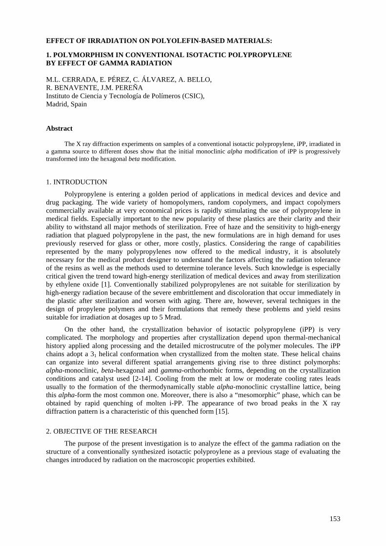
EFFECT OF IRRADIATION ON POLYOLEFIN-BASED MATERIALS: 1. POLYMORPHISM IN CONVENTIONAL ISOTACTIC POLYPROPYLENE BY EFFECT OF GAMMA RADIATION M.L. CERRADA, E. PÉREZ, C. ÁLVAREZ, A. BELLO, R. BENAVENTE, J.M. PEREÑA Instituto de Ciencia y Tecnología de Polímeros (CSIC), Madrid, Spain
Abstract
The X ray diffraction experiments on samples of a conventional isotactic polypropylene, iPP, irradiated in a gamma source to different doses show that the initial monoclinic alpha modification of iPP is progressively transformed into the hexagonal beta modification.
1. INTRODUCTION
Polypropylene is entering a golden period of applications in medical devices and device and drug packaging. The wide variety of homopolymers, random copolymers, and impact copolymers commercially available at very economical prices is rapidly stimulating the use of polypropylene in medical fields. Especially important to the new popularity of these plastics are their clarity and their ability to withstand all major methods of sterilization. Free of haze and the sensitivity to high-energy radiation that plagued polypropylene in the past, the new formulations are in high demand for uses previously reserved for glass or other, more costly, plastics. Considering the range of capabilities represented by the many polypropylenes now offered to the medical industry, it is absolutely necessary for the medical product designer to understand the factors affecting the radiation tolerance of the resins as well as the methods used to determine tolerance levels. Such knowledge is especially critical given the trend toward high-energy sterilization of medical devices and away from sterilization by ethylene oxide [1]. Conventionally stabilized polypropylenes are not suitable for sterilization by high-energy radiation because of the severe embrittlement and discoloration that occur immediately in the plastic after sterilization and worsen with aging. There are, however, several techniques in the design of propylene polymers and their formulations that remedy these problems and yield resins suitable for irradiation at dosages up to 5 Mrad.
On the other hand, the crystallization behavior of isotactic polypropylene (iPP) is very complicated. The morphology and properties after crystallization depend upon thermal-mechanical history applied along processing and the detailed microstrucutre of the polymer molecules. The iPP chains adopt a 31 helical conformation when crystallized from the molten state. These helical chains can organize into several different spatial arrangements giving rise to three distinct polymorphs: alpha-monoclinic, beta-hexagonal and gamma-orthorhombic forms, depending on the crystallization conditions and catalyst used [2-14]. Cooling from the melt at low or moderate cooling rates leads usually to the formation of the thermodynamically stable alpha-monoclinic crystalline lattice, being this alpha-form the most common one. Moreover, there is also a “mesomorphic” phase, which can be obtained by rapid quenching of molten i-PP. The appearance of two broad peaks in the X ray diffraction pattern is a characteristic of this quenched form [15].
2. OBJECTIVE OF THE RESEARCH
The purpose of the present investigation is to analyze the effect of the gamma radiation on the structure of a conventionally synthesized isotactic polyproylene as a previous stage of evaluating the changes introduced by radiation on the macroscopic properties exhibited.
153
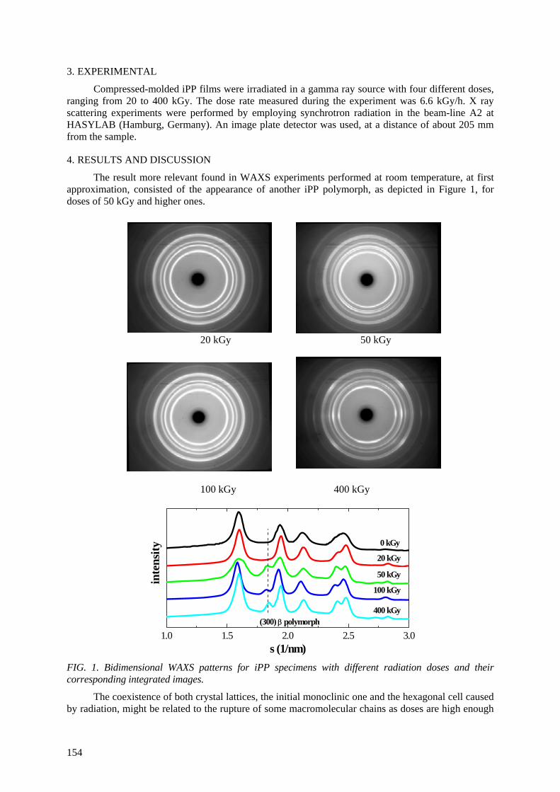
3. EXPERIMENTAL
Compressed-molded iPP films were irradiated in a gamma ray source with four different doses, ranging from 20 to 400 kGy. The dose rate measured during the experiment was 6.6 kGy/h. X ray scattering experiments were performed by employing synchrotron radiation in the beam-line A2 at HASYLAB (Hamburg, Germany). An image plate detector was used, at a distance of about 205 mm from the sample.
4. RESULTS AND DISCUSSION
The result more relevant found in WAXS experiments performed at room temperature, at first approximation, consisted of the appearance of another iPP polymorph, as depicted in Figure 1, for doses of 50 kGy and higher ones.
20 kGy 50 kGy
100 kGy 400 kGy
1.0 1.5 2.0 2.5 3.0
400 kGy
100 kGy
50 kGy
20 kGy
0 kGy
(300) β polymorph
inte
nsity
s (1/nm)
FIG. 1. Bidimensional WAXS patterns for iPP specimens with different radiation doses and their corresponding integrated images.
The coexistence of both crystal lattices, the initial monoclinic one and the hexagonal cell caused by radiation, might be related to the rupture of some macromolecular chains as doses are high enough
154

and the subsequent capability of those for organizing into this beta crystalline lattice. Anyway, these results have been acquired quite recently and a deeper analysis has to be done. Additionally, the effects of this structural change on the physical properties (mainly thermal and mechanical ones) and processability have to be explored due to the viable applicability of this irradiated material as aforementioned. Other interesting aspect to be explored at microscopic scale will reside in the subsequent repercussion on macroscopic behavior that this new arrangement imposes on deformation mechanism and during a further processing cycle.
ACKNOWLEDGEMENTS
This work was supported by the IHP-Contract HPRI-CT-1999-00040/2001-00140 of the European Commission, by Comunidad de Madrid (project 07N/0093/2002) and by MCYT (project MAT2001-1731). The support from the International Atomic Energy Agency (Research Agreement 12705/RO), in the framework of the Coordinated Research Project "Controlling of Degradation Effects in Radiation Processing of Polymers", is also acknowledged.
REFERENCES
[1] R.C., PORTNOY, "Polypropylene for Medical Device Applications", Med. Plas. Biomat. 1, 43 (1994).
[2] G., NATTA, P., CORRADINI, Nuovo Cimento Suppl. 15, 40 (1960). [3] H.D., KEITH, F.J., PADDEN JR., N.M., WALTER, H.W. WYCKOFF, J. Appl. Phys. 30, 1485
(1959). [4] A., TURNER JONES, J.M., AIZLEWOOD, D.R., BECKETT, MAKROMOL. Chem. 75, 134
(1964). [5] S.V., MEILLE, D.R., FERRO, S., BRÜCKNER, A.J. LOVINGER, F.J. PADDEN,
Macromolecules 27, 2615 (1994). [6] E.J., ADDINK, J., BEINTEMA, Polymer 2, 185 (1961). [7] S.V., MEILLE, S., BRÜCKNER, W., PORZIO, Macromolecules 23, 4114 (1990). [8] E., PÉREZ, D., ZUCCHI, M.L., SACCHI, F., FORLINI, A., BELLO, Polymer 40, 675 (1999). [9] A., TURNER-JONES, Polymer 12, 487 (1971). [10] R., THOMANN, C., WANG, J., KRESSLER, R., MULHAUPT, Macromolecules 29, 8425
(1996). [11] R., CAMPBELL, P., PHILLIPS, Polymer 34, 4809 (1993). [12] B., LOTZ, J., WITTMAN, A., LOVINGER, Polymer 37, 4979 (1996). [13] S., BRUCKNER, S., MEILLE, Nature 340, 455 (1989). [14] K., MEZGHANI, P., PHILLIPS, Polymer 38, 5725 (1997). [15] R., ANDROSCH, B., WUNDERLICH, Macromolecules 34, 5950 (2001).
155

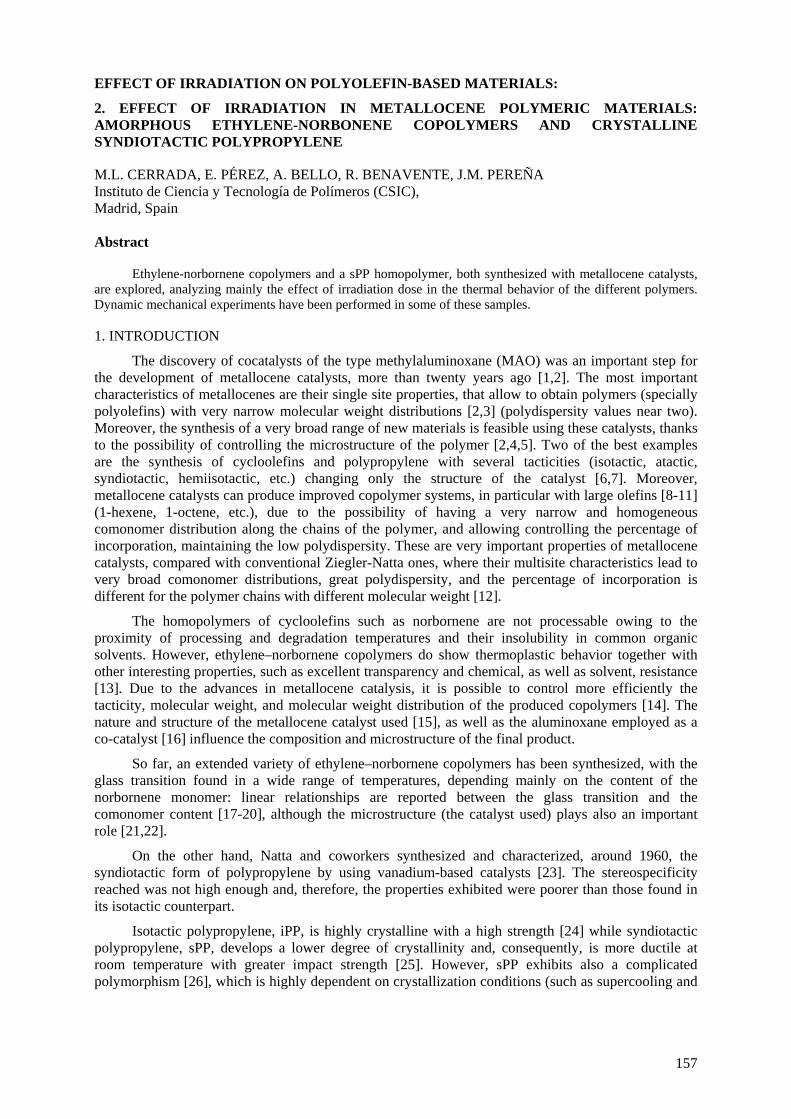
EFFECT OF IRRADIATION ON POLYOLEFIN-BASED MATERIALS:
2. EFFECT OF IRRADIATION IN METALLOCENE POLYMERIC MATERIALS: AMORPHOUS ETHYLENE-NORBONENE COPOLYMERS AND CRYSTALLINE SYNDIOTACTIC POLYPROPYLENE
M.L. CERRADA, E. PÉREZ, A. BELLO, R. BENAVENTE, J.M. PEREÑA Instituto de Ciencia y Tecnología de Polímeros (CSIC), Madrid, Spain Abstract
Ethylene-norbornene copolymers and a sPP homopolymer, both synthesized with metallocene catalysts, are explored, analyzing mainly the effect of irradiation dose in the thermal behavior of the different polymers. Dynamic mechanical experiments have been performed in some of these samples.
1. INTRODUCTION
The discovery of cocatalysts of the type methylaluminoxane (MAO) was an important step for the development of metallocene catalysts, more than twenty years ago [1,2]. The most important characteristics of metallocenes are their single site properties, that allow to obtain polymers (specially polyolefins) with very narrow molecular weight distributions [2,3] (polydispersity values near two). Moreover, the synthesis of a very broad range of new materials is feasible using these catalysts, thanks to the possibility of controlling the microstructure of the polymer [2,4,5]. Two of the best examples are the synthesis of cycloolefins and polypropylene with several tacticities (isotactic, atactic, syndiotactic, hemiisotactic, etc.) changing only the structure of the catalyst [6,7]. Moreover, metallocene catalysts can produce improved copolymer systems, in particular with large olefins [8-11] (1-hexene, 1-octene, etc.), due to the possibility of having a very narrow and homogeneous comonomer distribution along the chains of the polymer, and allowing controlling the percentage of incorporation, maintaining the low polydispersity. These are very important properties of metallocene catalysts, compared with conventional Ziegler-Natta ones, where their multisite characteristics lead to very broad comonomer distributions, great polydispersity, and the percentage of incorporation is different for the polymer chains with different molecular weight [12].
The homopolymers of cycloolefins such as norbornene are not processable owing to the proximity of processing and degradation temperatures and their insolubility in common organic solvents. However, ethylene–norbornene copolymers do show thermoplastic behavior together with other interesting properties, such as excellent transparency and chemical, as well as solvent, resistance [13]. Due to the advances in metallocene catalysis, it is possible to control more efficiently the tacticity, molecular weight, and molecular weight distribution of the produced copolymers [14]. The nature and structure of the metallocene catalyst used [15], as well as the aluminoxane employed as a co-catalyst [16] influence the composition and microstructure of the final product.
So far, an extended variety of ethylene–norbornene copolymers has been synthesized, with the glass transition found in a wide range of temperatures, depending mainly on the content of the norbornene monomer: linear relationships are reported between the glass transition and the comonomer content [17-20], although the microstructure (the catalyst used) plays also an important role [21,22].
On the other hand, Natta and coworkers synthesized and characterized, around 1960, the syndiotactic form of polypropylene by using vanadium-based catalysts [23]. The stereospecificity reached was not high enough and, therefore, the properties exhibited were poorer than those found in its isotactic counterpart.
Isotactic polypropylene, iPP, is highly crystalline with a high strength [24] while syndiotactic polypropylene, sPP, develops a lower degree of crystallinity and, consequently, is more ductile at room temperature with greater impact strength [25]. However, sPP exhibits also a complicated polymorphism [26], which is highly dependent on crystallization conditions (such as supercooling and
157
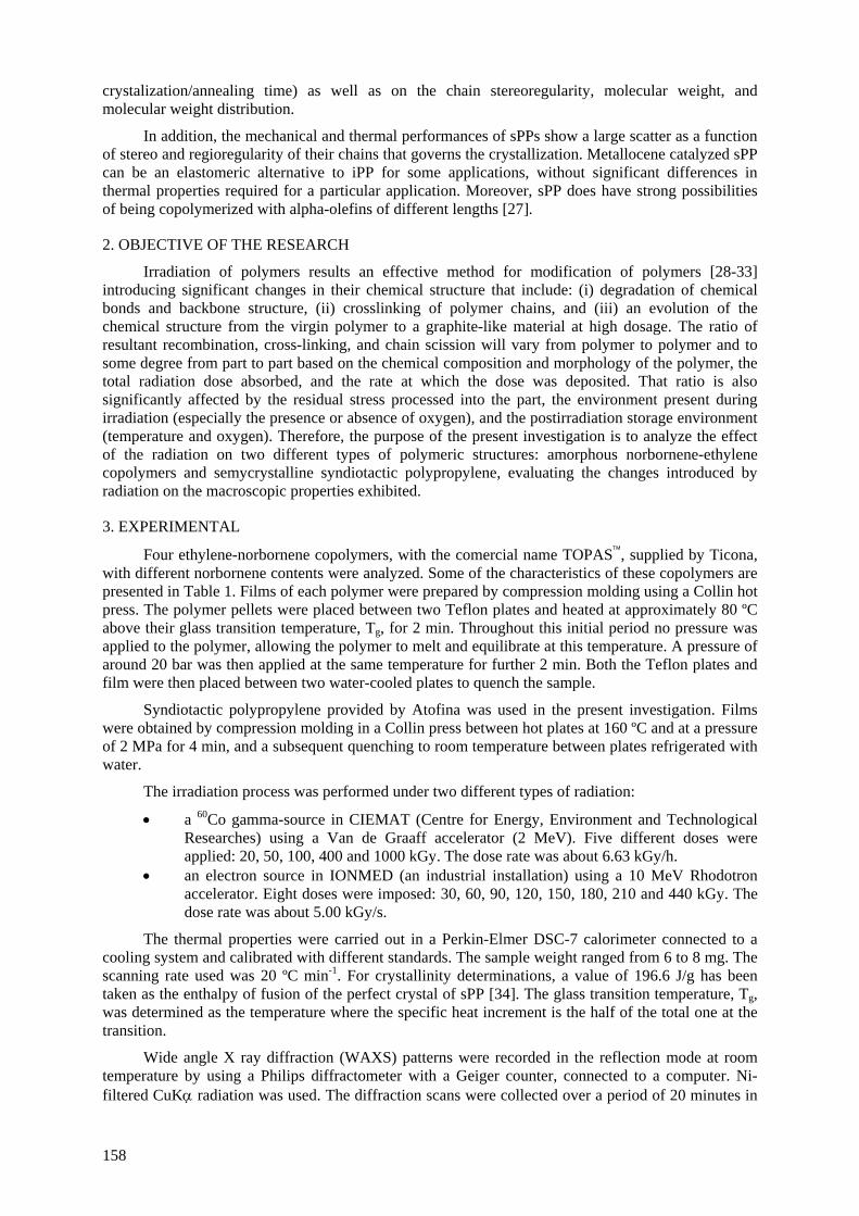
crystalization/annealing time) as well as on the chain stereoregularity, molecular weight, and molecular weight distribution.
In addition, the mechanical and thermal performances of sPPs show a large scatter as a function of stereo and regioregularity of their chains that governs the crystallization. Metallocene catalyzed sPP can be an elastomeric alternative to iPP for some applications, without significant differences in thermal properties required for a particular application. Moreover, sPP does have strong possibilities of being copolymerized with alpha-olefins of different lengths [27].
2. OBJECTIVE OF THE RESEARCH
Irradiation of polymers results an effective method for modification of polymers [28-33] introducing significant changes in their chemical structure that include: (i) degradation of chemical bonds and backbone structure, (ii) crosslinking of polymer chains, and (iii) an evolution of the chemical structure from the virgin polymer to a graphite-like material at high dosage. The ratio of resultant recombination, cross-linking, and chain scission will vary from polymer to polymer and to some degree from part to part based on the chemical composition and morphology of the polymer, the total radiation dose absorbed, and the rate at which the dose was deposited. That ratio is also significantly affected by the residual stress processed into the part, the environment present during irradiation (especially the presence or absence of oxygen), and the postirradiation storage environment (temperature and oxygen). Therefore, the purpose of the present investigation is to analyze the effect of the radiation on two different types of polymeric structures: amorphous norbornene-ethylene copolymers and semycrystalline syndiotactic polypropylene, evaluating the changes introduced by radiation on the macroscopic properties exhibited.
3. EXPERIMENTAL
Four ethylene-norbornene copolymers, with the comercial name TOPAS™, supplied by Ticona, with different norbornene contents were analyzed. Some of the characteristics of these copolymers are presented in Table 1. Films of each polymer were prepared by compression molding using a Collin hot press. The polymer pellets were placed between two Teflon plates and heated at approximately 80 ºC above their glass transition temperature, Tg, for 2 min. Throughout this initial period no pressure was applied to the polymer, allowing the polymer to melt and equilibrate at this temperature. A pressure of around 20 bar was then applied at the same temperature for further 2 min. Both the Teflon plates and film were then placed between two water-cooled plates to quench the sample.
Syndiotactic polypropylene provided by Atofina was used in the present investigation. Films were obtained by compression molding in a Collin press between hot plates at 160 ºC and at a pressure of 2 MPa for 4 min, and a subsequent quenching to room temperature between plates refrigerated with water.
The irradiation process was performed under two different types of radiation:
• a 60Co gamma-source in CIEMAT (Centre for Energy, Environment and Technological Researches) using a Van de Graaff accelerator (2 MeV). Five different doses were applied: 20, 50, 100, 400 and 1000 kGy. The dose rate was about 6.63 kGy/h.
• an electron source in IONMED (an industrial installation) using a 10 MeV Rhodotron accelerator. Eight doses were imposed: 30, 60, 90, 120, 150, 180, 210 and 440 kGy. The dose rate was about 5.00 kGy/s.
The thermal properties were carried out in a Perkin-Elmer DSC-7 calorimeter connected to a cooling system and calibrated with different standards. The sample weight ranged from 6 to 8 mg. The scanning rate used was 20 ºC min-1. For crystallinity determinations, a value of 196.6 J/g has been taken as the enthalpy of fusion of the perfect crystal of sPP [34]. The glass transition temperature, Tg, was determined as the temperature where the specific heat increment is the half of the total one at the transition.
Wide angle X ray diffraction (WAXS) patterns were recorded in the reflection mode at room temperature by using a Philips diffractometer with a Geiger counter, connected to a computer. Ni-filtered CuKα radiation was used. The diffraction scans were collected over a period of 20 minutes in
158
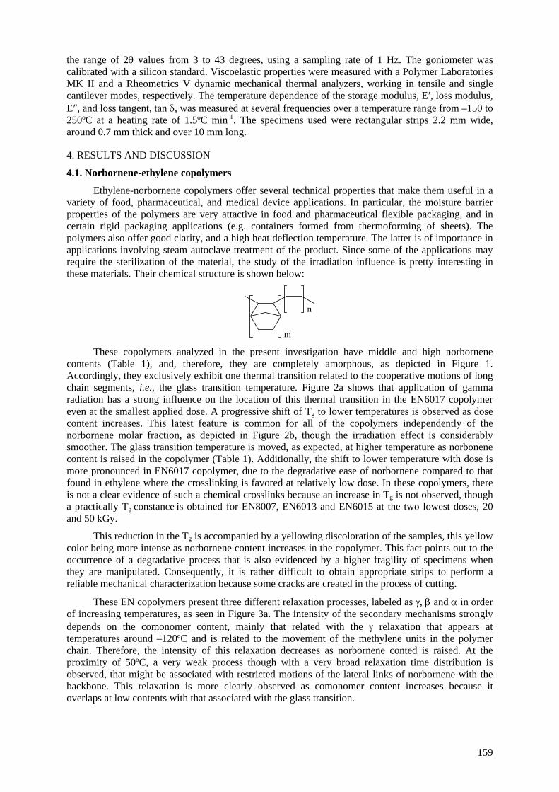
the range of 2θ values from 3 to 43 degrees, using a sampling rate of 1 Hz. The goniometer was calibrated with a silicon standard. Viscoelastic properties were measured with a Polymer Laboratories MK II and a Rheometrics V dynamic mechanical thermal analyzers, working in tensile and single cantilever modes, respectively. The temperature dependence of the storage modulus, E′, loss modulus, E″, and loss tangent, tan δ, was measured at several frequencies over a temperature range from –150 to 250ºC at a heating rate of 1.5ºC min-1. The specimens used were rectangular strips 2.2 mm wide, around 0.7 mm thick and over 10 mm long.
4. RESULTS AND DISCUSSION
4.1. Norbornene-ethylene copolymers
Ethylene-norbornene copolymers offer several technical properties that make them useful in a variety of food, pharmaceutical, and medical device applications. In particular, the moisture barrier properties of the polymers are very attactive in food and pharmaceutical flexible packaging, and in certain rigid packaging applications (e.g. containers formed from thermoforming of sheets). The polymers also offer good clarity, and a high heat deflection temperature. The latter is of importance in applications involving steam autoclave treatment of the product. Since some of the applications may require the sterilization of the material, the study of the irradiation influence is pretty interesting in these materials. Their chemical structure is shown below:
m
n
These copolymers analyzed in the present investigation have middle and high norbornene
contents (Table 1), and, therefore, they are completely amorphous, as depicted in Figure 1. Accordingly, they exclusively exhibit one thermal transition related to the cooperative motions of long chain segments, i.e., the glass transition temperature. Figure 2a shows that application of gamma radiation has a strong influence on the location of this thermal transition in the EN6017 copolymer even at the smallest applied dose. A progressive shift of Tg to lower temperatures is observed as dose content increases. This latest feature is common for all of the copolymers independently of the norbornene molar fraction, as depicted in Figure 2b, though the irradiation effect is considerably smoother. The glass transition temperature is moved, as expected, at higher temperature as norbonene content is raised in the copolymer (Table 1). Additionally, the shift to lower temperature with dose is more pronounced in EN6017 copolymer, due to the degradative ease of norbornene compared to that found in ethylene where the crosslinking is favored at relatively low dose. In these copolymers, there is not a clear evidence of such a chemical crosslinks because an increase in Tg is not observed, though a practically Tg constance is obtained for EN8007, EN6013 and EN6015 at the two lowest doses, 20 and 50 kGy.
This reduction in the Tg is accompanied by a yellowing discoloration of the samples, this yellow color being more intense as norbornene content increases in the copolymer. This fact points out to the occurrence of a degradative process that is also evidenced by a higher fragility of specimens when they are manipulated. Consequently, it is rather difficult to obtain appropriate strips to perform a reliable mechanical characterization because some cracks are created in the process of cutting.
These EN copolymers present three different relaxation processes, labeled as γ, β and α in order of increasing temperatures, as seen in Figure 3a. The intensity of the secondary mechanisms strongly depends on the comonomer content, mainly that related with the γ relaxation that appears at temperatures around –120ºC and is related to the movement of the methylene units in the polymer chain. Therefore, the intensity of this relaxation decreases as norbornene conted is raised. At the proximity of 50ºC, a very weak process though with a very broad relaxation time distribution is observed, that might be associated with restricted motions of the lateral links of norbornene with the backbone. This relaxation is more clearly observed as comonomer content increases because it overlaps at low contents with that associated with the glass transition.
159
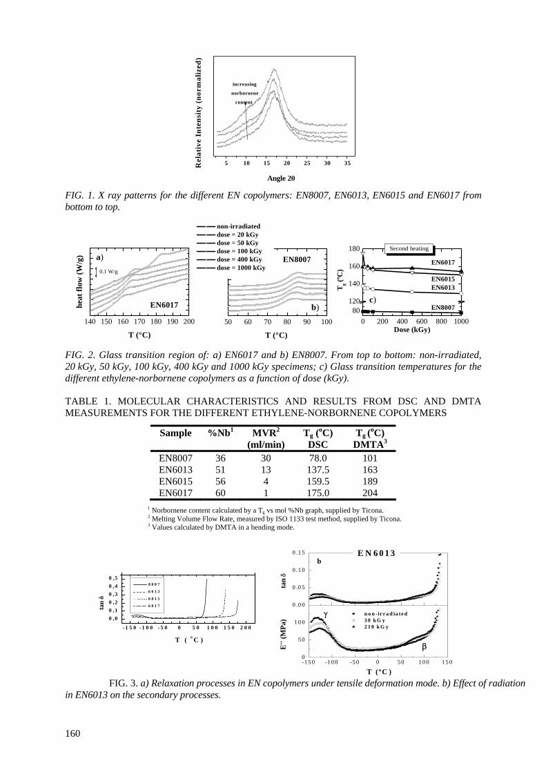
5 10 15 20 25 30 35
Angle 2θ (o)
Rel
ativ
e In
tens
ity
(nor
mal
ized
)
increasing
norbornene
content
FIG. 1. X ray patterns for the different EN copolymers: EN8007, EN6013, EN6015 and EN6017 from bottom to top.
140 150 160 170 180 190 200
a)
EN6017
0.1 W/g
heat
flow
(W/g
)
T (°C)
50 60 70 80 90 100
b)
EN8007
non-irradiated dose = 20 kGy dose = 50 kGy dose = 100 kGy dose = 400 kGy dose = 1000 kGy
T (°C)
0 200 400 600 800 100080
120
140
160
180
c)
EN6017
EN6013EN6015
EN8007
Second heating
T g (ºC
)Dose (kGy)
FIG. 2. Glass transition region of: a) EN6017 and b) EN8007. From top to bottom: non-irradiated, 20 kGy, 50 kGy, 100 kGy, 400 kGy and 1000 kGy specimens; c) Glass transition temperatures for the different ethylene-norbornene copolymers as a function of dose (kGy). TABLE 1. MOLECULAR CHARACTERISTICS AND RESULTS FROM DSC AND DMTA MEASUREMENTS FOR THE DIFFERENT ETHYLENE-NORBORNENE COPOLYMERS
Sample %Nb1 MVR2
(ml/min) Tg (oC) DSC
Tg (oC) DMTA3
EN8007 36 30 78.0 101 EN6013 51 13 137.5 163 EN6015 56 4 159.5 189 EN6017 60 1 175.0 204
1 Norbornene content calculated by a Tg vs mol %Nb graph, supplied by Ticona. 2 Melting Volume Flow Rate, measured by ISO 1133 test method, supplied by Ticona. 3 Values calculated by DMTA in a bending mode.
- 1 5 0 - 1 0 0 - 5 0 0 5 0 1 0 0 1 5 0 2 0 0
0 ,00 ,10 ,20 ,30 ,40 ,5
8 0 0 7
6 0 1 3
6 0 1 5
6 0 1 7tan δ
T ( o C )
-1 5 0 -1 0 0 -5 0 0 5 0 1 0 0 1 5 00
5 0
1 0 0
0 .0 0
0 .0 5
0 .1 0
0 .1 5
β
γ
E'' (
MPa
)
T ( ºC )
b
n o n -ir r a d ia te d 3 0 k G y 2 1 0 k G y
E N 6 0 1 3
tan
δ
FIG. 3. a) Relaxation processes in EN copolymers under tensile deformation mode. b) Effect of radiation in EN6013 on the secondary processes.
160
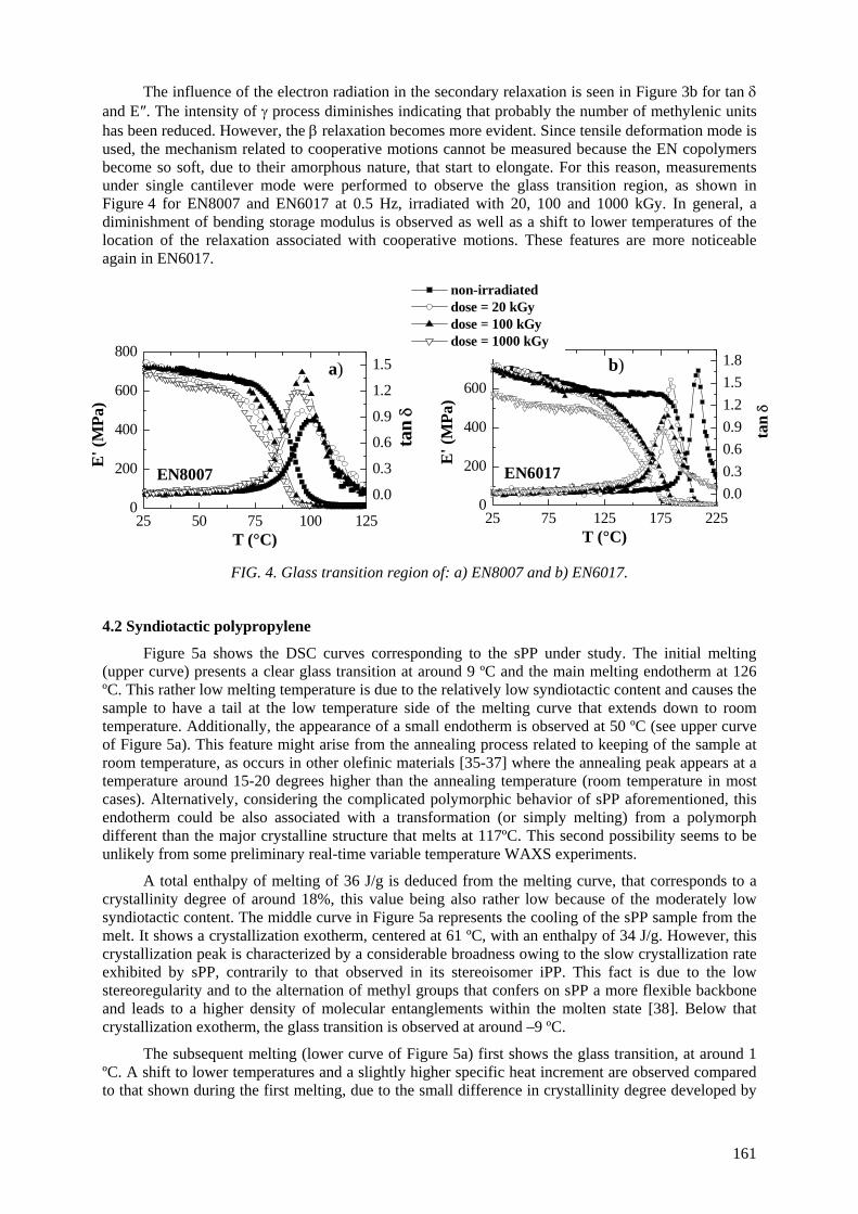
The influence of the electron radiation in the secondary relaxation is seen in Figure 3b for tan δ and E″. The intensity of γ process diminishes indicating that probably the number of methylenic units has been reduced. However, the β relaxation becomes more evident. Since tensile deformation mode is used, the mechanism related to cooperative motions cannot be measured because the EN copolymers become so soft, due to their amorphous nature, that start to elongate. For this reason, measurements under single cantilever mode were performed to observe the glass transition region, as shown in Figure 4 for EN8007 and EN6017 at 0.5 Hz, irradiated with 20, 100 and 1000 kGy. In general, a diminishment of bending storage modulus is observed as well as a shift to lower temperatures of the location of the relaxation associated with cooperative motions. These features are more noticeable again in EN6017.
FIG. 4. Glass transition region of: a) EN8007 and b) EN6017.
4.2 Syndiotactic polypropylene
Figure 5a shows the DSC curves corresponding to the sPP under study. The initial melting (upper curve) presents a clear glass transition at around 9 ºC and the main melting endotherm at 126 ºC. This rather low melting temperature is due to the relatively low syndiotactic content and causes the sample to have a tail at the low temperature side of the melting curve that extends down to room temperature. Additionally, the appearance of a small endotherm is observed at 50 ºC (see upper curve of Figure 5a). This feature might arise from the annealing process related to keeping of the sample at room temperature, as occurs in other olefinic materials [35-37] where the annealing peak appears at a temperature around 15-20 degrees higher than the annealing temperature (room temperature in most cases). Alternatively, considering the complicated polymorphic behavior of sPP aforementioned, this endotherm could be also associated with a transformation (or simply melting) from a polymorph different than the major crystalline structure that melts at 117ºC. This second possibility seems to be unlikely from some preliminary real-time variable temperature WAXS experiments.
A total enthalpy of melting of 36 J/g is deduced from the melting curve, that corresponds to a crystallinity degree of around 18%, this value being also rather low because of the moderately low syndiotactic content. The middle curve in Figure 5a represents the cooling of the sPP sample from the melt. It shows a crystallization exotherm, centered at 61 ºC, with an enthalpy of 34 J/g. However, this crystallization peak is characterized by a considerable broadness owing to the slow crystallization rate exhibited by sPP, contrarily to that observed in its stereoisomer iPP. This fact is due to the low stereoregularity and to the alternation of methyl groups that confers on sPP a more flexible backbone and leads to a higher density of molecular entanglements within the molten state [38]. Below that crystallization exotherm, the glass transition is observed at around –9 ºC.
The subsequent melting (lower curve of Figure 5a) first shows the glass transition, at around 1 ºC. A shift to lower temperatures and a slightly higher specific heat increment are observed compared to that shown during the first melting, due to the small difference in crystallinity degree developed by
25 50 75 100 1250
200
400
600
800
E
' (M
Pa)
T (°C)
0.0
0.3
0.6
0.9
1.2
1.5a)
EN8007
tan
δ
25 75 125 175 2250
200
400
600
800
E
' (M
Pa)
T (°C)
0.00.30.60.91.21.51.8
non-irradiated dose = 20 kGy dose = 100 kGy
b) dose = 1000 kGy
EN6017
tan
δ
161
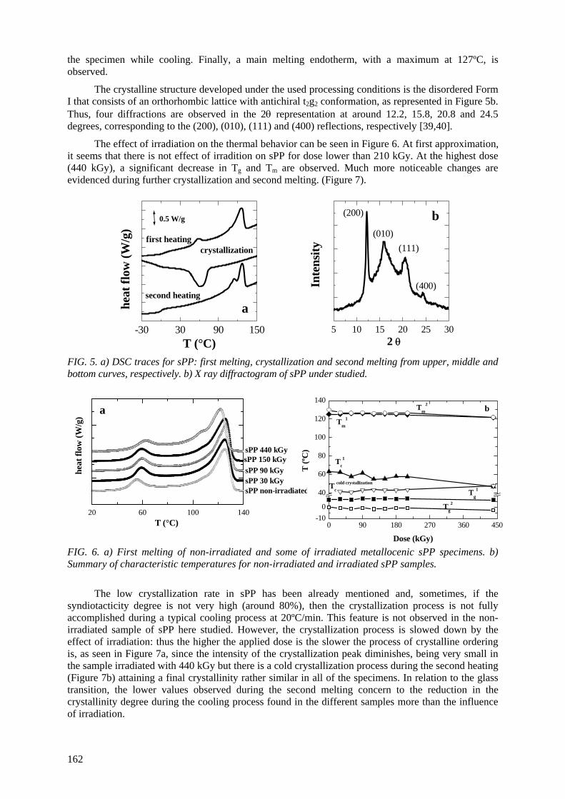
the specimen while cooling. Finally, a main melting endotherm, with a maximum at 127ºC, is observed.
The crystalline structure developed under the used processing conditions is the disordered Form I that consists of an orthorhombic lattice with antichiral t2g2 conformation, as represented in Figure 5b. Thus, four diffractions are observed in the 2θ representation at around 12.2, 15.8, 20.8 and 24.5 degrees, corresponding to the (200), (010), (111) and (400) reflections, respectively [39,40].
The effect of irradiation on the thermal behavior can be seen in Figure 6. At first approximation, it seems that there is not effect of irradition on sPP for dose lower than 210 kGy. At the highest dose (440 kGy), a significant decrease in Tg and Tm are observed. Much more noticeable changes are evidenced during further crystallization and second melting. (Figure 7).
-30 30 90 150 5 10 15 20 25 30
second heating
crystallizationfirst heating
a
0.5 W/g
heat
flow
(W/g
)
T (°C)
b(010)
(111)
(400)
(200)
Inte
nsity
2 θ
FIG. 5. a) DSC traces for sPP: first melting, crystallization and second melting from upper, middle and bottom curves, respectively. b) X ray diffractogram of sPP under studied.
FIG. 6. a) First melting of non-irradiated and some of irradiated metallocenic sPP specimens. b) Summary of characteristic temperatures for non-irradiated and irradiated sPP samples.
The low crystallization rate in sPP has been already mentioned and, sometimes, if the syndiotacticity degree is not very high (around 80%), then the crystallization process is not fully accomplished during a typical cooling process at 20ºC/min. This feature is not observed in the non-irradiated sample of sPP here studied. However, the crystallization process is slowed down by the effect of irradiation: thus the higher the applied dose is the slower the process of crystalline ordering is, as seen in Figure 7a, since the intensity of the crystallization peak diminishes, being very small in the sample irradiated with 440 kGy but there is a cold crystallization process during the second heating (Figure 7b) attaining a final crystallinity rather similar in all of the specimens. In relation to the glass transition, the lower values observed during the second melting concern to the reduction in the crystallinity degree during the cooling process found in the different samples more than the influence of irradiation.
20 60 100 140
a
sPP 90 kGysPP 150 kGysPP 440 kGy
sPP 30 kGysPP non-irradiated
heat
flow
(W/g
)
T (°C) 0 90 180 270 360 450-10
0
40
60
80
100
120
140
bTm
1
Tc1
Tccold crystallization
Tg2
Tg1
Tm2
T (ºC
)
Dose (kGy)
162
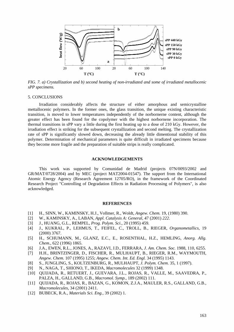
20 60 100 14020 60 100
b
/g)
sPP 0 kGysPP 30 kGysPP 90 kGy
sPP 150 kGysPP 440 kGy
T (°C)
a
T (ºC)
heat
flow
(W FIG. 7. a) Crystallization and b) second heating of non-irradiated and some of irradiated metallocenic sPP specimens. 5. CONCLUSIONS
Irradiation considerably affects the structure of either amorphous and semicrystalline mettallocenic polymers. In the former ones, the glass transition, the unique existing characteristic transition, is moved to lower temperatures independently of the norbornerne content, although the greater effect has been found for the copolymer with the highest norbornene incorporation. The thermal transitions in sPP vary a little during the first heating up to a dose of 210 kGy. However, the irradiation effect is striking for the subsequent crystallization and second melting. The crystallization rate of sPP is significantly slowed down, decreasing the already little dimentional stability of this polymer. Determination of mechanical parameters is quite difficult in irradiated specimens because they become more fragile and the preparation of suitable strips is really complicated.
ACKNOWLEDGEMENTS
This work was supported by Comunidad de Madrid (projects 07N/0093/2002 and GR/MAT/0728/2004) and by MEC (project MAT2004-01547). The support from the International Atomic Energy Agency (Research Agreement 12705/RO), in the framework of the Coordinated Research Project "Controlling of Degradation Effects in Radiation Processing of Polymers", is also acknowledged.
REFERENCES
[1] H., SINN, W., KAMINSKY, H.J., Vollmer, R., Woldt, Angew. Chem. 19, (1980) 390. [2] W., KAMINSKY, A., LABAN, Appl. Catalysis A: General, 47 (2001) 222. [3] J., HUANG, G.L., REMPEL, Prog. Polym. Sci., 20 (1995) 459. [4] J., KUKRAL, P., LEHMUS, T., FEIFEL, C., TROLL, B., RIEGER, Organometallics, 19
(2000) 3767. [5] H., SCHUMANN, M., GLANZ, E.C., E., ROSENTHAL, H.Z., HEMLING, Anorg. Allg.
Chem., 622 (1996) 1865. [6] J.A., EWEN, R.L., JONES, A., RAZAVI, J.D., FERRARA, J. Am. Chem. Soc. 1988, 110, 6255. [7] H.H., BRINTZINGER, D., FISCHER, R., MULHAUPT, B., RIEGER, R.M., WAYMOUTH,
Angew. Chem. 107 (1995) 1255; Angew. Chem. Int. Ed. Engl. 34 (1995) 1143. [8] S., JUNGLING, S., KOLTZENBURG, R., MULHAUPT, J. Polym. Chem. 35, 1 (1997). [9] N., NAGA, T., SHIONO, T., IKEDA, Macromolecules 32 (1999) 1348. [10] QUIJADA, R., RETUERT, J., GUEVARA, J.L., ROJAS, R., VALLE, M., SAAVEDRA, P.,
PALZA, H., GALLAND, G.B., Macromol. Symp., 189 (2002) 111. [11] QUIJADA, R., ROJAS, R., BAZAN, G., KOMON, Z.J.A., MAULER, R.S., GALLAND, G.B.,
Macromolecules, 34 (2001) 2411. [12] BUBECK, R.A., Materials Sci. Eng., 39 (2002) 1.
163
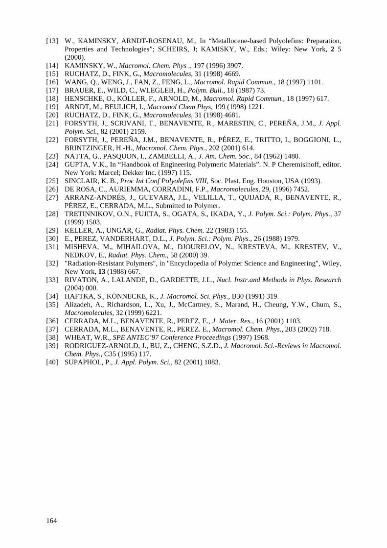
[13] W., KAMINSKY, ARNDT-ROSENAU, M., In “Metallocene-based Polyolefins: Preparation, Properties and Technologies”; SCHEIRS, J; KAMISKY, W., Eds.; Wiley: New York, 2 5 (2000).
[14] KAMINSKY, W., Macromol. Chem. Phys ., 197 (1996) 3907. [15] RUCHATZ, D., FINK, G., Macromolecules, 31 (1998) 4669. [16] WANG, Q., WENG, J., FAN, Z., FENG, L., Macromol. Rapid Commun., 18 (1997) 1101. [17] BRAUER, E., WILD, C., WLEGLEB, H., Polym. Bull., 18 (1987) 73. [18] HENSCHKE, O., KÖLLER, F., ARNOLD, M., Macromol. Rapid Commun., 18 (1997) 617. [19] ARNDT, M., BEULICH, I., Macromol Chem Phys, 199 (1998) 1221. [20] RUCHATZ, D., FINK, G., Macromolecules, 31 (1998) 4681. [21] FORSYTH, J., SCRIVANI, T., BENAVENTE, R., MARESTIN, C., PEREÑA, J.M., J. Appl.
Polym. Sci., 82 (2001) 2159. [22] FORSYTH, J., PEREÑA, J.M., BENAVENTE, R., PÉREZ, E., TRITTO, I., BOGGIONI, L.,
BRINTZINGER, H.-H., Macromol. Chem. Phys., 202 (2001) 614. [23] NATTA, G., PASQUON, I., ZAMBELLI, A., J. Am. Chem. Soc., 84 (1962) 1488. [24] GUPTA, V.K., In “Handbook of Engineering Polymeric Materials”. N. P Cheremisinoff, editor.
New York: Marcel; Dekker Inc. (1997) 115. [25] SINCLAIR, K. B., Proc Int Conf Polyolefins VIII, Soc. Plast. Eng. Houston, USA (1993). [26] DE ROSA, C., AURIEMMA, CORRADINI, F.P., Macromolecules, 29, (1996) 7452. [27] ARRANZ-ANDRÉS, J., GUEVARA, J.L., VELILLA, T., QUIJADA, R., BENAVENTE, R.,
PÉREZ, E., CERRADA, M.L., Submitted to Polymer. [28] TRETINNIKOV, O.N., FUJITA, S., OGATA, S., IKADA, Y., J. Polym. Sci.: Polym. Phys., 37
(1999) 1503. [29] KELLER, A., UNGAR, G., Radiat. Phys. Chem. 22 (1983) 155. [30] E., PEREZ, VANDERHART, D.L., J. Polym. Sci.: Polym. Phys., 26 (1988) 1979. [31] MISHEVA, M., MIHAILOVA, M., DJOURELOV, N., KRESTEVA, M., KRESTEV, V.,
NEDKOV, E., Radiat. Phys. Chem., 58 (2000) 39. [32] "Radiation-Resistant Polymers", in "Encyclopedia of Polymer Science and Engineering", Wiley,
New York, 13 (1988) 667. [33] RIVATON, A., LALANDE, D., GARDETTE, J.L., Nucl. Instr.and Methods in Phys. Research
(2004) 000. [34] HAFTKA, S., KÖNNECKE, K., J. Macromol. Sci. Phys., B30 (1991) 319. [35] Alizadeh, A., Richardson, L., Xu, J., McCartney, S., Marand, H., Cheung, Y.W., Chum, S.,
Macromolecules, 32 (1999) 6221. [36] CERRADA, M.L., BENAVENTE, R., PEREZ, E., J. Mater. Res., 16 (2001) 1103. [37] CERRADA, M.L., BENAVENTE, R., PEREZ. E., Macromol. Chem. Phys., 203 (2002) 718. [38] WHEAT, W.R., SPE ANTEC’97 Conference Proceedings (1997) 1968. [39] RODRIGUEZ-ARNOLD, J., BU, Z., CHENG, S.Z.D., J. Macromol. Sci.-Reviews in Macromol.
Chem. Phys., C35 (1995) 117. [40] SUPAPHOL, P., J. Appl. Polym. Sci., 82 (2001) 1083.
164
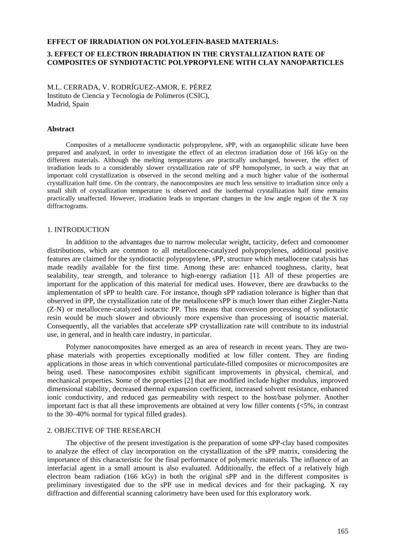
EFFECT OF IRRADIATION ON POLYOLEFIN-BASED MATERIALS:
3. EFFECT OF ELECTRON IRRADIATION IN THE CRYSTALLIZATION RATE OF COMPOSITES OF SYNDIOTACTIC POLYPROPYLENE WITH CLAY NANOPARTICLES
M.L. CERRADA, V. RODRÍGUEZ-AMOR, E. PÉREZ Instituto de Ciencia y Tecnología de Polímeros (CSIC), Madrid, Spain
Abstract
Composites of a metallocene syndiotactic polypropylene, sPP, with an organophilic silicate have been prepared and analyzed, in order to investigate the effect of an electron irradiation dose of 166 kGy on the different materials. Although the melting temperatures are practically unchanged, however, the effect of irradiation leads to a considerably slower crystallization rate of sPP homopolymer, in such a way that an important cold crystallization is observed in the second melting and a much higher value of the isothermal crystallization half time. On the contrary, the nanocomposites are much less sensitive to irradiation since only a small shift of crystallization temperature is observed and the isothermal crystallization half time remains practically unaffected. However, irradiation leads to important changes in the low angle region of the X ray diffractograms.
1. INTRODUCTION
In addition to the advantages due to narrow molecular weight, tacticity, defect and comonomer distributions, which are common to all metallocene-catalyzed polypropylenes, additional positive features are claimed for the syndiotactic polypropylene, sPP, structure which metallocene catalysis has made readily available for the first time. Among these are: enhanced toughness, clarity, heat sealability, tear strength, and tolerance to high-energy radiation [1]. All of these properties are important for the application of this material for medical uses. However, there are drawbacks to the implementation of sPP to health care. For instance, though sPP radiation tolerance is higher than that observed in iPP, the crystallization rate of the metallocene sPP is much lower than either Ziegler-Natta (Z-N) or metallocene-catalyzed isotactic PP. This means that conversion processing of syndiotactic resin would be much slower and obviously more expensive than processing of isotactic material. Consequently, all the variables that accelerate sPP crystallization rate will contribute to its industrial use, in general, and in health care industry, in particular.
Polymer nanocomposites have emerged as an area of research in recent years. They are two-phase materials with properties exceptionally modified at low filler content. They are finding applications in those areas in which conventional particulate-filled composites or microcomposites are being used. These nanocomposites exhibit significant improvements in physical, chemical, and mechanical properties. Some of the properties [2] that are modified include higher modulus, improved dimensional stability, decreased thermal expansion coefficient, increased solvent resistance, enhanced ionic conductivity, and reduced gas permeability with respect to the host/base polymer. Another important fact is that all these improvements are obtained at very low filler contents ( <5%, in contrast to the 30–40% normal for typical filled grades).
2. OBJECTIVE OF THE RESEARCH
The objective of the present investigation is the preparation of some sPP-clay based composites to analyze the effect of clay incorporation on the crystallization of the sPP matrix, considering the importance of this characteristic for the final performance of polymeric materials. The influence of an interfacial agent in a small amount is also evaluated. Additionally, the effect of a relatively high electron beam radiation (166 kGy) in both the original sPP and in the different composites is preliminary investigated due to the sPP use in medical devices and for their packaging. X ray diffraction and differential scanning calorimetry have been used for this exploratory work.
165
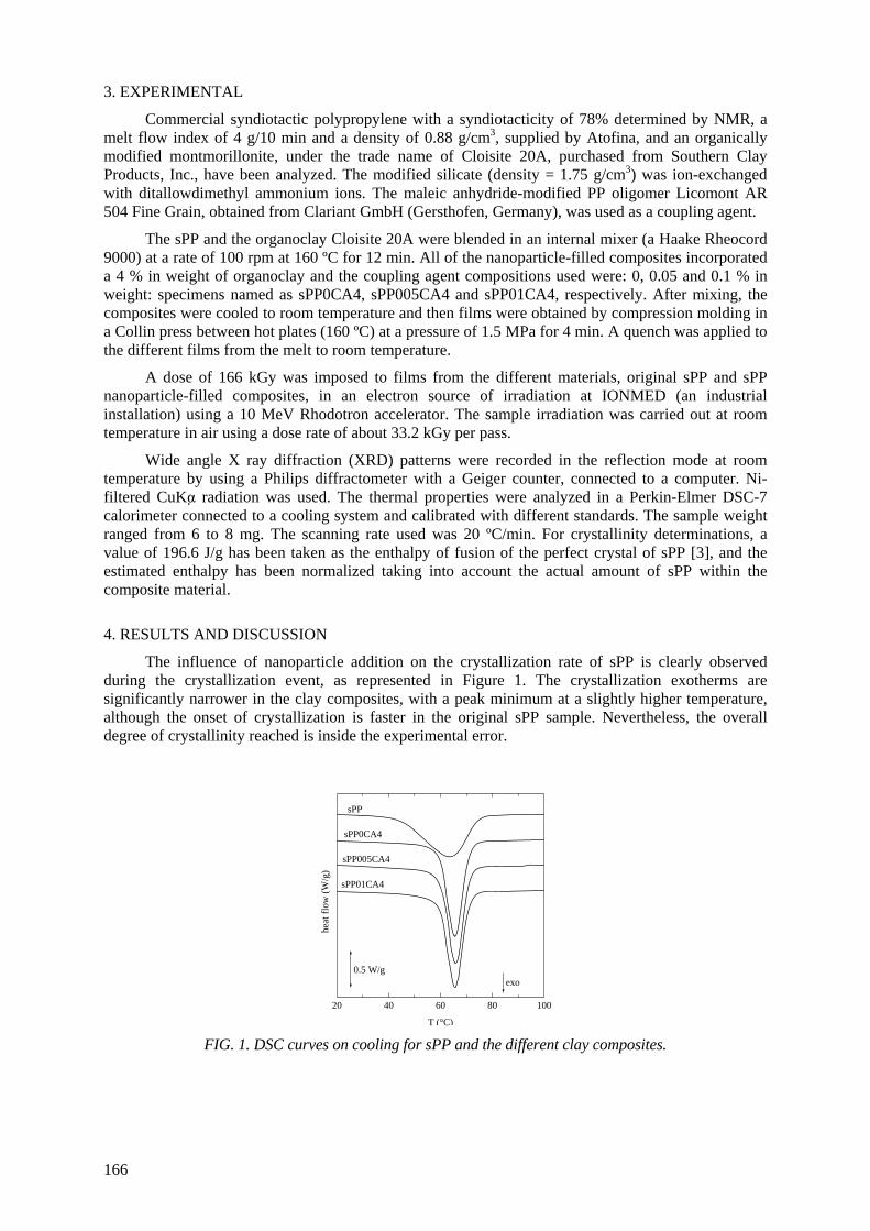
3. EXPERIMENTAL
Commercial syndiotactic polypropylene with a syndiotacticity of 78% determined by NMR, a melt flow index of 4 g/10 min and a density of 0.88 g/cm3, supplied by Atofina, and an organically modified montmorillonite, under the trade name of Cloisite 20A, purchased from Southern Clay Products, Inc., have been analyzed. The modified silicate (density = 1.75 g/cm3) was ion-exchanged with ditallowdimethyl ammonium ions. The maleic anhydride-modified PP oligomer Licomont AR 504 Fine Grain, obtained from Clariant GmbH (Gersthofen, Germany), was used as a coupling agent.
The sPP and the organoclay Cloisite 20A were blended in an internal mixer (a Haake Rheocord 9000) at a rate of 100 rpm at 160 ºC for 12 min. All of the nanoparticle-filled composites incorporated a 4 % in weight of organoclay and the coupling agent compositions used were: 0, 0.05 and 0.1 % in weight: specimens named as sPP0CA4, sPP005CA4 and sPP01CA4, respectively. After mixing, the composites were cooled to room temperature and then films were obtained by compression molding in a Collin press between hot plates (160 ºC) at a pressure of 1.5 MPa for 4 min. A quench was applied to the different films from the melt to room temperature.
A dose of 166 kGy was imposed to films from the different materials, original sPP and sPP nanoparticle-filled composites, in an electron source of irradiation at IONMED (an industrial installation) using a 10 MeV Rhodotron accelerator. The sample irradiation was carried out at room temperature in air using a dose rate of about 33.2 kGy per pass.
Wide angle X ray diffraction (XRD) patterns were recorded in the reflection mode at room temperature by using a Philips diffractometer with a Geiger counter, connected to a computer. Ni-filtered CuKα radiation was used. The thermal properties were analyzed in a Perkin-Elmer DSC-7 calorimeter connected to a cooling system and calibrated with different standards. The sample weight ranged from 6 to 8 mg. The scanning rate used was 20 ºC/min. For crystallinity determinations, a value of 196.6 J/g has been taken as the enthalpy of fusion of the perfect crystal of sPP [3], and the estimated enthalpy has been normalized taking into account the actual amount of sPP within the composite material.
4. RESULTS AND DISCUSSION
The influence of nanoparticle addition on the crystallization rate of sPP is clearly observed during the crystallization event, as represented in Figure 1. The crystallization exotherms are significantly narrower in the clay composites, with a peak minimum at a slightly higher temperature, although the onset of crystallization is faster in the original sPP sample. Nevertheless, the overall degree of crystallinity reached is inside the experimental error.
20 40 60 80 100
exo0.5 W/g
sPP005CA4
sPP0CA4
sPP01CA4
sPP
heat
flow
(W/g
)
T (°C) FIG. 1. DSC curves on cooling for sPP and the different clay composites.
166

167
Figure 2 points out nearly the same characteristics in the clay composites during second heating
than those found in the original sPP. The main endothermic peak does not vary its location and
crystallinity is kept practically constant by incorporation of the layered silicate. However, the low-
temperature peak of the split melting endotherm, centered at around 114 ºC, becomes sharper and
more intense in the clay composites. A series of experiments with a constant cooling rate but different
subsequent heating rates shows that the high-temperature component decreases its relative intensity as
the heating rate increases, indicating, most probably, that this component arises from recrystallization
of the crystallites initially formed. The distinct relative proportions of the two melting peaks between
the original sPP and the nanocomposities are indicative of a change in the recrystallization ability by
effect of the clay nanoparticles.
Figure 3 evidences the significant influence of radiation in the XRD patterns at middle angles for the
different clay composites when comparing to the profiles for the non-irradiated samples. A new
diffraction peak appears in the interval from 2.5 to 2.85º. The corresponding basal distances ranged
from 3.53 to 3.10 nm. It seems, therefore, that irradiation of the different sPP-clay composite materials
has made possible the intercalation of the sPP macromolecules within the clay layers leading to the
obtaining of nanocomposites. This fact might be ascribed to the development of some polar groups by
electron irradiation that enhances compatibility [4] between the different components within the
composite material, ensuring better cohesion and leading to sPP chains intercalation. However, the
sPP macroscopic crystalline structure remains practically unaltered, as observed in the wide angle
region (Figure 3b).
-25 0 25 50 75 100 125 150
endo
0.5 W/g
sPP01CA4
sPP0CA4
sPP005CA4
sPP
hea
t fl
ow
(W
/g)
T (°C)
FIG. 2. Second melting DSC curves for sPP and the different clay composites.
8 14 20 26 32
(b)
sPP01CA4
sPP0CA4
sPP
rel.
inte
nsi
ty
2θ
2 4 6 8 10
(a)
sPP005CA4
sPP
sPP0CA4
sPP01CA4
rel.
inte
nsi
ty
cloisite 20A
2θ
FIG. 3. XRD patterns for the different samples irradiated at 166 kGy in the middle (a) and wide (b)
angle regions.
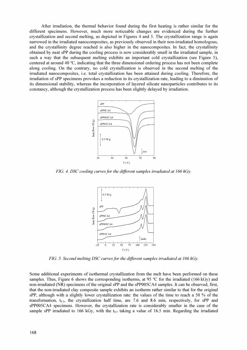
168
After irradiation, the thermal behavior found during the first heating is rather similar for the
different specimens. However, much more noticeable changes are evidenced during the further crystallization and second melting, as depicted in Figures 4 and 5. The crystallization range is again
narrowed in the irradiated nanocomposites, as previously observed in their non-irradiated homologous, and the crystallinity degree reached is also higher in the nanocomposites. In fact, the crystallinity
obtained by neat sPP during the cooling process is now considerably small in the irradiated sample, in such a way that the subsequent melting exhibits an important cold crystallization (see Figure 5), centered at around 40 ºC, indicating that the three dimensional ordering process has not been complete
along cooling. On the contrary, no cold crystallization is observed in the second melting of the irradiated nanocomposites, i.e. total crystallization has been attained during cooling. Therefore, the
irradiation of sPP specimens provokes a reduction in its crystallization rate, leading to a diminution of its dimensional stability, whereas the incorporation of layered silicate nanoparticles contributes to its constancy, although the crystallization process has been slightly delayed by irradiation.
10 30 50 70 90
exo
sPP01CA4
0.5 W/g
sPP005CA4
sPP0CA4
sPP
hea
t fl
ow
(W
/g)
T (°C)
FIG. 4. DSC cooling curves for the different samples irradiated at 166 kGy.
-25 0 25 50 75 100 125 150
endo
hea
t fl
ow
(W
/g)
sPP01CA4
sPP005CA4
sPP0CA4
sPP
0.5 W/g
T (°C)
FIG. 5. Second melting DSC curves for the different samples irradiated at 166 kGy.
Some additional experiments of isothermal crystallization from the melt have been performed on these
samples. Thus, Figure 6 shows the corresponding isotherms, at 95 ºC for the irradiated (166 kGy) and non-irradiated (NR) specimens of the original sPP and the sPP005CA4 samples. It can be observed, first,
that the non-irradiated clay composite sample exhibits an isotherm rather similar to that for the original sPP, although with a slightly lower crystallization rate: the values of the time to reach a 50 % of the
transformation, t0.5, the crystallization half time, are 7.6 and 8.6 min, respectively, for sPP and sPP005CA4 specimens. However, the crystallization rate is considerably smaller in the case of the sample sPP irradiated to 166 kGy, with the t0.5 taking a value of 16.5 min. Regarding the irradiated
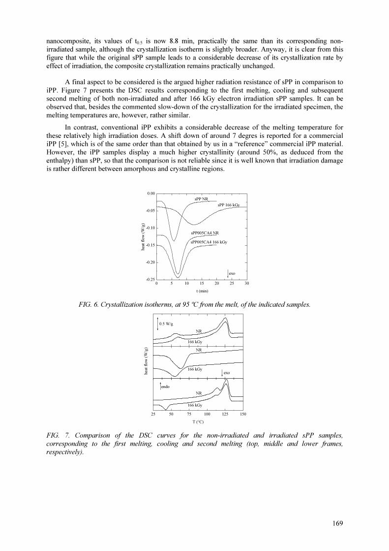
169
nanocomposite, its values of t0.5 is now 8.8 min, practically the same than its corresponding non-
irradiated sample, although the crystallization isotherm is slightly broader. Anyway, it is clear from this figure that while the original sPP sample leads to a considerable decrease of its crystallization rate by
effect of irradiation, the composite crystallization remains practically unchanged.
A final aspect to be considered is the argued higher radiation resistance of sPP in comparison to
iPP. Figure 7 presents the DSC results corresponding to the first melting, cooling and subsequent second melting of both non-irradiated and after 166 kGy electron irradiation sPP samples. It can be observed that, besides the commented slow-down of the crystallization for the irradiated specimen, the
melting temperatures are, however, rather similar.
In contrast, conventional iPP exhibits a considerable decrease of the melting temperature for
these relatively high irradiation doses. A shift down of around 7 degres is reported for a commercial iPP [5], which is of the same order than that obtained by us in a “reference” commercial iPP material. However, the iPP samples display a much higher crystallinity (around 50%, as deduced from the
enthalpy) than sPP, so that the comparison is not reliable since it is well known that irradiation damage is rather different between amorphous and crystalline regions.
0 5 10 15 20 25 30-0.25
-0.20
-0.15
-0.10
-0.05
0.00
exo
sPP005CA4 166 kGy
sPP005CA4 NR
sPP 166 kGy
sPP NR
hea
t fl
ow
(W
/g)
t (min)
FIG. 6. Crystallization isotherms, at 95 ºC from the melt, of the indicated samples.
25 50 75 100 125 150
166 kGy
NR
0.5 W/g
exo
endo
166 kGy
NR
hea
t fl
ow
(W
/g)
166 kGy
NR
T (°C)
FIG. 7. Comparison of the DSC curves for the non-irradiated and irradiated sPP samples,
corresponding to the first melting, cooling and second melting (top, middle and lower frames, respectively).
170
ACKNOWLEDGEMENTS
This work was funded by Comunidad de Madrid (projects 07N/0093/2002 and GR/MAT/0728/2004) and by Ministerio de Educación y Ciencia (projects MAT2004-06999-C02-01
and MAT2005-00228). The supports from the Exchange Collaboration Program Bulgarian Academy of Sciences and the Spanish Council for Scientific Research (project 2004BG0017), from the
European Commission (COST Action D17, WG D17/0004/00) and from the International Atomic Energy Agency (Research Agreement 12705/RO), in the framework of the Coordinated Research Project "Controlling of Degradation Effects in Radiation Processing of Polymers", are also
acknowledged.
REFERENCES
[1] PORTNOY, R., DOMINE, C.J.D., In “Metallocene-Based Polyolefins”, J. Scheirs and W. KAMINSKY Eds.; John Wiley & Sons Ltd: New York, 2 22 (2000).
[2] WALTER, P., MADER, D., REICHERT, P., MULHAUPT R., J. Macromol. Sci. Pure Appl. Chem. A36 (1999) 1613.
[3] HAFTKA, S., KÖNNECKE, K., J. Macromol. Sci. Phys. B30 (1991) 319. [4] CHENG, S., KERLUKE, D.R., SPE ANTEC’03 (2003). [5] STOJANOVIĆ, Z., KAČAREVIĆ–POPOVIĆ, Z., GALOVIĆ, S., MILIČEVIĆ, D.,
SULJOVRUJIĆ, E., Polym. Degrad. Stabil. 87 (2005) 279.
THE USE OF RADIATION-INDUCED DEGRADATION IN:
I. CONTROLLED DEGRADATION OF ISOPRENE/ISOBUTENE RUBBER II. CONTROLLING MOLECULAR WEIGHTS OF POLYSACCHARIDES III. CONTROLLING THE CONDUCTIVITY OF POLYANILINE BLENDS
VIA IN-SITU DEHYDROCHLORINATION OF PVC O. GÜVEN Department of Chemistry, Hacettepe University, Ankara, Turkey Abstract Better understanding of chemistry of radiation-induced degradation is becoming of increasing importance on account of the utilization of polymeric materials in a variety of radiation environments as well as beneficial uses of degraded polymers. In this report degrading effects of radiation have been considered from the points of view of controlled degradation of isoprene/isobutene rubbers for recycling purposes and controlling the molecular weights of kappa- and iota-carrageenans and alginates and controlling the conductivity of polyaniline blends by in-situ doping via radiation-induced HCl released from poly(vinyl chloride) and iys copolymers. I. CONTROLLED DEGRADATION OF ISOPRENE/ISOBUTENE RUBBER I.1. INTRODUCTION
Thermoset polymeric materials, such as rubber tires are of great challenge concerning the environmental and ecological reasons in regard to their treatment methods. Ionizing radiation seems to offer unique opportunities to tackle the problem of recycling of polymers and rubbers on account of its ability to cause cross-linking or/and chain scission of polymeric materials.
There have been many works in the literature dealing with the radiation-induced breakdown of
a variety of polymers. Some alteration of the molecular structure and/or morphology of the material may even be enhanced if as reported by Burillo et al.[1] in reclaiming polymer and rubber wastes, by the use of ionizing radiation.
Although literature is full of publications dealing with the recycling of waste tires [2-4], only a
limited amount of work reported on the effect of irradiation conditions and additives on the radiation-induced degradation of rubbers.
In this study we investigated the effect of dose rate and irradiation atmosphere on the
degradation of uncrosslinked, commercial isobutylene-isoprene (IIR) rubber. The effect of radiation-induced degradation on the molecular weight has been investigated by chromatographic, and viscosimetric techniques. I.2. EXPERIMENTAL Materials Three commercial isobutylene–isoprene (IIP) rubber samples were used in our experiments: Ex165 (isoprene content: 0.8%) and Ex 268 (isoprene content: 1.7%) were obtained from Exxon company, and BK1685N(isoprene content: 1.7%) was obtained from the Nizhnekamsk company. All these butyl rubbers were used as received. Gamma Irradiation IIP specimens of dimensions in 2 cm × 2 cm with 5 mm thicknesses were irradiated at ambient temperature in air and nitrogen purged and sealed glass ampoules in Gammacell 220 type Canadian
171

172
made γ-irradiator for low dose rate(0.18 kGy/h) irradiations and Isslodovately model Russian made γ irradiatior for high dose rate(3.0kGy/h) irradiations.
Viscosimetric Studies
The limiting viscosity number [η] of the rubbers were determined by using the Huggins equation:
ηsp/c = [η] + k’[η]2c (1)
Where k’ is constant for a given polymer at a given temperature in a given solvent, and c is the concentration of solution. The viscosities of solutions were measured in an Ubbelohde type viscometer, tetrahydrofuran (THF) being the solvent used throughout the experiments. The thermostat temperature was maintained at 25 ± 0.02 ºC for all measurements. Size Exclusion Chromatography Studies
Weight-and number-average molecular weights of unirradiated and irradiated rubber samples were determined by using a Waters 244 ALC/GPC chromatograph equipped with four Ultrastyragel columns with pore sizes 106-105-104-103 Å, and THF as the eluting solvent. The flow rate was kept at 1 ml/min in all cases. A universal calibration curve based on the elution volume of polyethylene glycol(PEG) standards from Toyo Soda Company and using appropriate Mark-Houwink-Sakurada constants, K = 2.0 × 10⁻⁴ and a = 0.67 for butyl rubber in THF[5] was constructed.
I.3. RESULTS AND DISCUSSION
Effect of gamma rays on the limiting viscosity number of IIR
In order to see the effect of irradiation dose rate and atmosphere on the degradation of rubber samples, the limiting viscosity numbers were first determined. Figs 1 a, b, and c, show the effect of atmosphere on the limiting viscosity number of butyl rubber at low dose rate irradiation (0.18 kGy/h). Cross-linking reactions occur in most elastomers when treated with ionizing radiation, but only a few rubber varieties such as butyl rubber and butyl vulcanizates whose structural units contain quaternary carbon atoms undergo appreciable degradation reactions [6]. As shown in Fig. 1, limiting viscosity values of rubber samples used in this work decrease significantly up to 100 kGy irradiation dose but do not change appreciably beyond this dose value. Slightly higher values of degradation was observed for low dose rate irradiation in air than in nitrogen for a given absorbed dose value. This is presumably due to the longer contact of rubber with oxygen in air and resulting in higher chain scission reactions [7]. On the other hand no significant dependence of limiting viscosity or average molecular weight on the irradiation atmosphere was observed for rubber samples following high dose rate irradiation(3.0 kGy/h), most probably due shorter contact time of the rubber with oxygen.
FIG.1. Variation of limiting viscosity values with irradiation dose, for low dose rate. Irradiation (0.18kGy/h) in air and N2; (a) Ex165, (b) Ex 268, Effect of irradiation conditions on the G(S) and
G(X) values of IIP
0 50 100 150 200
0.0
0.2
0.4
0.6
0.8
1.0
1.2
N2
Air
Lim
itin
g v
isco
sity
num
ber
[η
] (
dl/
g)
Dose (kGy)
0 50 100 150 2000.0
0.2
0.4
0.6
0.8
1.0
1.2
N2
Air
Lim
itin
g v
isco
sity
num
ber
[η
] (
dl/
g)
Dose (kGy)
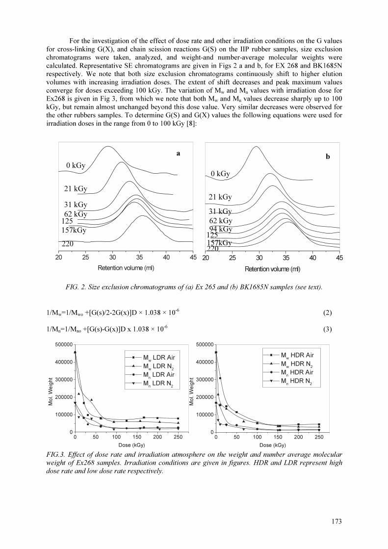
173
For the investigation of the effect of dose rate and other irradiation conditions on the G values for cross-linking G(X), and chain scission reactions G(S) on the IIP rubber samples, size exclusion chromatograms were taken, analyzed, and weight-and number-average molecular weights were calculated. Representative SE chromatograms are given in Figs 2 a and b, for EX 268 and BK1685N respectively. We note that both size exclusion chromatograms continuously shift to higher elution volumes with increasing irradiation doses. The extent of shift decreases and peak maximum values converge for doses exceeding 100 kGy. The variation of Mw and Mn values with irradiation dose for Ex268 is given in Fig 3, from which we note that both Mw and Mn values decrease sharply up to 100 kGy, but remain almost unchanged beyond this dose value. Very similar decreases were observed for the other rubbers samples. To determine G(S) and G(X) values the following equations were used for irradiation doses in the range from 0 to 100 kGy [8]:
FIG. 2. Size exclusion chromatograms of (a) Ex 265 and (b) BK1685N samples (see text).
1/Mw=1/Mwo +[G(s)/2-2G(x)]D × 1.038 × 10⁻⁶ (2)
1/Mn=1/Mno +[G(s)-G(x)]D x 1.038 × 10⁻⁶ (3)
FIG.3. Effect of dose rate and irradiation atmosphere on the weight and number average molecular weight of Ex268 samples. Irradiation conditions are given in figures. HDR and LDR represent high dose rate and low dose rate respectively.
62 kGy
0 kGy
21 kGy
31 kGy
125
157kGy
220
20 25 30 35 40 45
Retention volume (ml)
20 25 30 35 40 45
Retention volume (ml)
0 kGy
21 kGy
31 kGy
125 157kGy 220
62 kGy 94 kGy
a b
0 50 100 150 200 2500
100000
200000
300000
400000
500000
Mw LDR Air
Mw LDR N
2
Mn LDR Air
Mn LDR N
2
Mol. W
eig
ht
Dose (kGy)
0 50 100 150 200 2500
100000
200000
300000
400000
500000
Mw HDR Air
Mw HDR N
2
Mn HDR Air
Mn HDR N
2
Mol. W
eig
ht
Dose (kGy)
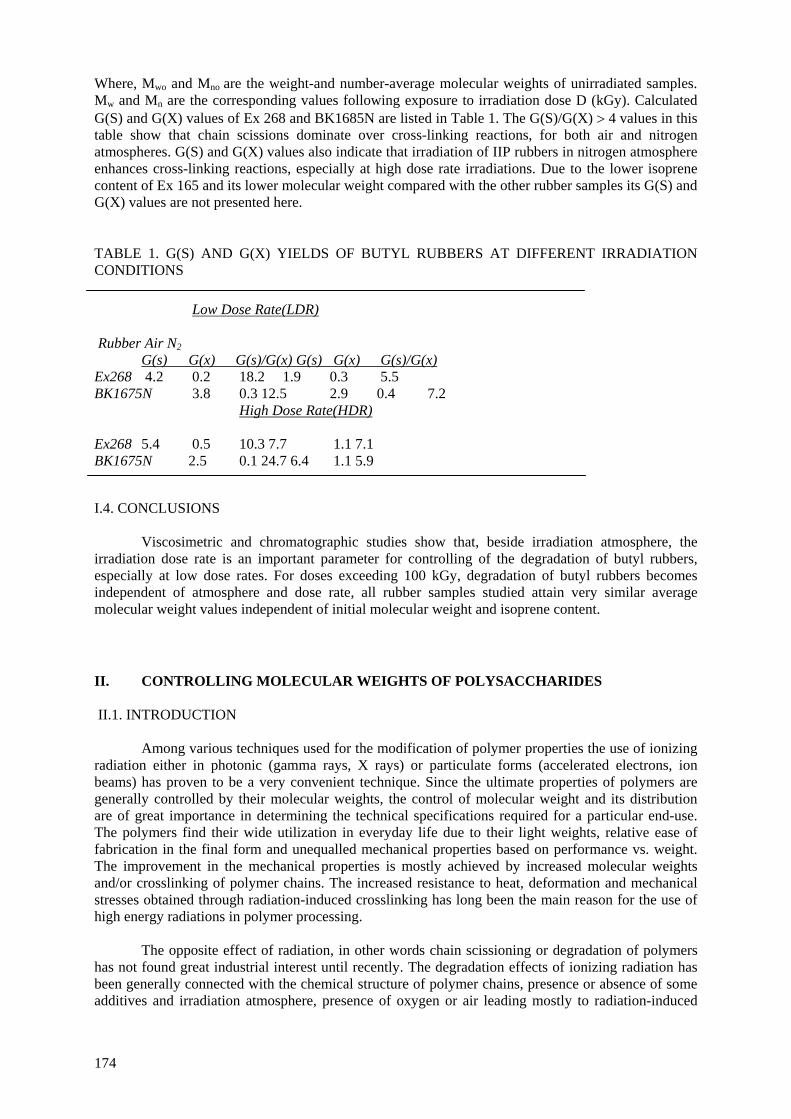
Where, Mwo and Mno are the weight-and number-average molecular weights of unirradiated samples. Mw and Mn are the corresponding values following exposure to irradiation dose D (kGy). Calculated G(S) and G(X) values of Ex 268 and BK1685N are listed in Table 1. The G(S)/G(X) > 4 values in this table show that chain scissions dominate over cross-linking reactions, for both air and nitrogen atmospheres. G(S) and G(X) values also indicate that irradiation of IIP rubbers in nitrogen atmosphere enhances cross-linking reactions, especially at high dose rate irradiations. Due to the lower isoprene content of Ex 165 and its lower molecular weight compared with the other rubber samples its G(S) and G(X) values are not presented here.
TABLE 1. G(S) AND G(X) YIELDS OF BUTYL RUBBERS AT DIFFERENT IRRADIATION CONDITIONS
Low Dose Rate(LDR) Rubber Air N2 G(s) G(x) G(s)/G(x) G(s) G(x) G(s)/G(x) Ex268 4.2 0.2 18.2 1.9 0.3 5.5 BK1675N 3.8 0.3 12.5 2.9 0.4 7.2
High Dose Rate(HDR) Ex268 5.4 0.5 10.3 7.7 1.1 7.1 BK1675N 2.5 0.1 24.7 6.4 1.1 5.9 I.4. CONCLUSIONS
Viscosimetric and chromatographic studies show that, beside irradiation atmosphere, the irradiation dose rate is an important parameter for controlling of the degradation of butyl rubbers, especially at low dose rates. For doses exceeding 100 kGy, degradation of butyl rubbers becomes independent of atmosphere and dose rate, all rubber samples studied attain very similar average molecular weight values independent of initial molecular weight and isoprene content.
II. CONTROLLING MOLECULAR WEIGHTS OF POLYSACCHARIDES II.1. INTRODUCTION
Among various techniques used for the modification of polymer properties the use of ionizing radiation either in photonic (gamma rays, X rays) or particulate forms (accelerated electrons, ion beams) has proven to be a very convenient technique. Since the ultimate properties of polymers are generally controlled by their molecular weights, the control of molecular weight and its distribution are of great importance in determining the technical specifications required for a particular end-use. The polymers find their wide utilization in everyday life due to their light weights, relative ease of fabrication in the final form and unequalled mechanical properties based on performance vs. weight. The improvement in the mechanical properties is mostly achieved by increased molecular weights and/or crosslinking of polymer chains. The increased resistance to heat, deformation and mechanical stresses obtained through radiation-induced crosslinking has long been the main reason for the use of high energy radiations in polymer processing.
The opposite effect of radiation, in other words chain scissioning or degradation of polymers
has not found great industrial interest until recently. The degradation effects of ionizing radiation has been generally connected with the chemical structure of polymer chains, presence or absence of some additives and irradiation atmosphere, presence of oxygen or air leading mostly to radiation-induced
174

oxidation. It has been amply shown that polymers carrying quaternary carbon atoms in the main chain suffer from chain scission. Poly(methyl methacrylate), polyisobutylene, poly(α-methyl styrene) are typical degrading type of polymers. Most of the natural and synthetic polymers carrying oxygen atom in their main chains also degrade upon irradiation. Poly(oxyethylene), cellulose and other polysaccharides are examples with repeating -C-O- groups on their backbones undergoing main chain scissioning. A different interpretation of structure vs. chain scissioning sensitivity is based on the heat of polymerization of monomers. Polymers showing relatively low heats of polymerization tend mostly to degrade upon irradiation. Although polymers can be categorized into two groups according to their ultimate response to high energy radiation as crosslinking and degrading types, exceptions to this classification can always be found. Poly(tetrafluoro ethylene) is one such example showing exclusively degradation upon irradiation at ambient temperature. In order to compare quantitatively the radiation response of polymers the amount of chemical changes should be related to the radiation energy absorbed. The efficiency of radiation-induced events is expressed by the so-called G-value. The G-value is equal to the number of events per 100 eV of energy absorbed has been customarily used to measure radiation chemical yield, but μmol/J is now recommended (1 μmol/J=10G).
Scission and crosslinking decrease or increase, respectively the molecular weights of the
polymer molecules. Therefore measurement of the changes in molecular weight averages or distributiun with dose can quantify these processes. Viscometric measurements in solution to give [η] indicate whether crosslinking or scission predominates. [η] values then will give Mv, provided that K and a for the Mark-Houwink relation are known. If the molecular weight distribution is known then Mn can be derived from Mv which can further be used to calculate the scission yield G(S). Molecular weights obtained from [η] values can be misleading if the initial molecular weight distribution is different from the most probable. An initially broad distribution will become narrow and turn into the most probable distribution with irradiation dose if there is only scission and G(S) will be overestimated from Mv values. Crosslinking reduces the ratio of hydrodynamic volume to molecular weight compared to linear molecules and [η] values will then lead to underestimation of the molecular weight. Gel Permeation Chromatography (GPC) is used widely to determine the average molecular weights and distribution of polymers. GPC suffers from the same hydrodynamic volume problem when crosslinking occurs, but this is generally ignored.
Polymers in which crosslinking predominates over scission, as determined by G(S)<4G(X),
become incompletely soluble above the gel dose, Dg and it is possible to derive values of G(S) and G(X) from measurements of the soluble or insoluble(gel) fraction of the polymer as a function of dose. A.Charlesby was the first in analysing quantitatively radiation response of polymers, a short account of his approach is given below[19].
Calculation of G(S) and G(X) from molecular weights
The relationship between average molecular weights and G(S) and G(X) are given in the
equations below: 1/MnD = 1/Mn0 + 1.04 × 10⁻¹⁰ [ G(S) – G(X) ] D ……………………… (1) 1/MwD = 1/Mw0 + 5.18 × 10⁻¹¹ [ G(S) – 4G(X) ] D…………………….. (2) where the dose D is given in Gy and subscripts D and 0 denote irradiated and unirradiated cases. Equation 1 applies to all initial molecular weight distributions. Equation 2 is the relationship between Mw and dose for an initial most probable molecular weight distribution. If scission only occurs then either equation 1 or 2 alone can be used to calculate G(S). When both crosslinking and scission occur G(S) and G(X) can be obtained from the combination of two equations provided that initial molecular weight distribution is the most probable.
If scission is the only mode of action of radiation then the radiation-chemical yield of degradation (scission) G(S) is determined from the Alexander-Charlesby-Ross equation:
175
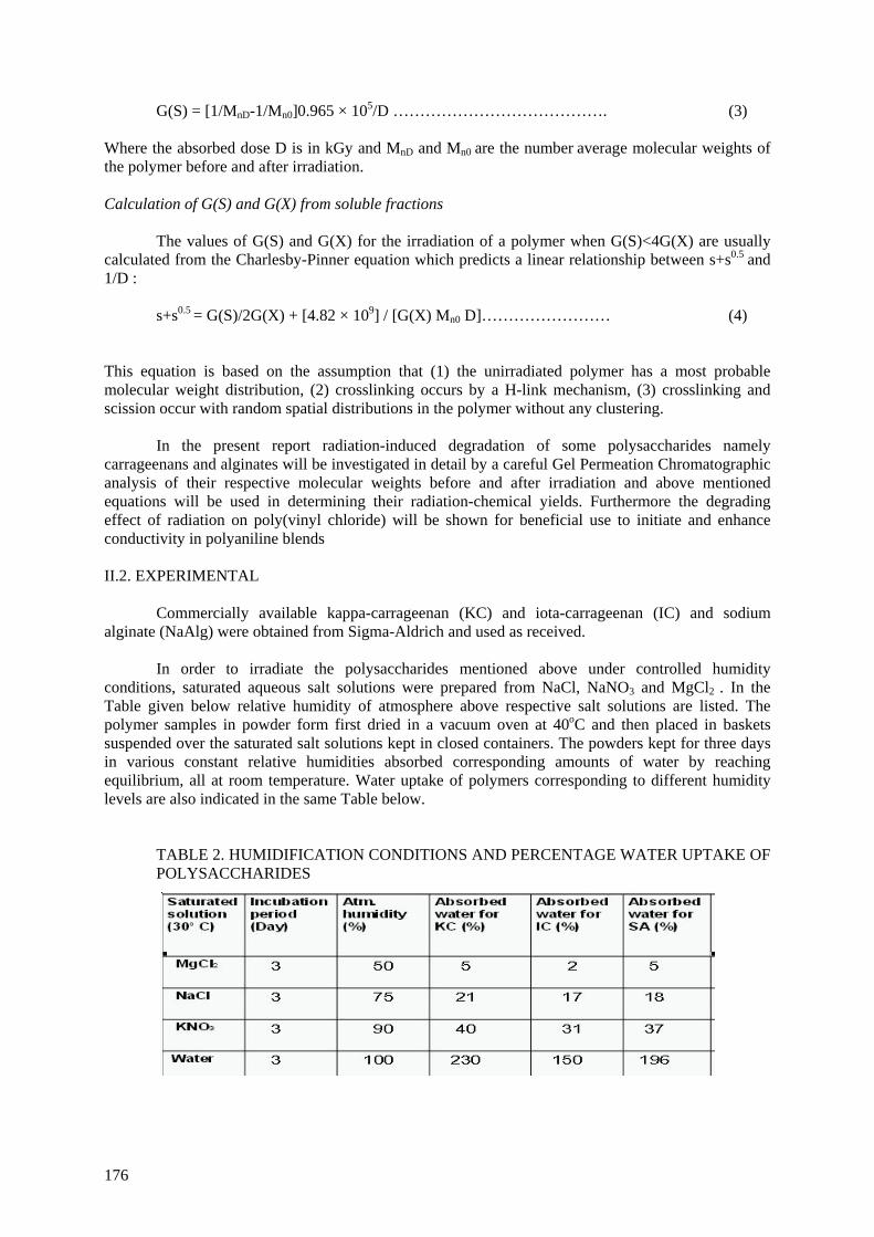
G(S) = [1/MnD-1/Mn0]0.965 × 105/D …………………………………. (3) Where the absorbed dose D is in kGy and MnD and Mn0 are the number average molecular weights of the polymer before and after irradiation. Calculation of G(S) and G(X) from soluble fractions
The values of G(S) and G(X) for the irradiation of a polymer when G(S)<4G(X) are usually
calculated from the Charlesby-Pinner equation which predicts a linear relationship between s+s0.5 and 1/D :
s+s0.5 = G(S)/2G(X) + [4.82 × 10⁹] / [G(X) Mn0 D]…………………… (4)
This equation is based on the assumption that (1) the unirradiated polymer has a most probable molecular weight distribution, (2) crosslinking occurs by a H-link mechanism, (3) crosslinking and scission occur with random spatial distributions in the polymer without any clustering.
In the present report radiation-induced degradation of some polysaccharides namely carrageenans and alginates will be investigated in detail by a careful Gel Permeation Chromatographic analysis of their respective molecular weights before and after irradiation and above mentioned equations will be used in determining their radiation-chemical yields. Furthermore the degrading effect of radiation on poly(vinyl chloride) will be shown for beneficial use to initiate and enhance conductivity in polyaniline blends II.2. EXPERIMENTAL
Commercially available kappa-carrageenan (KC) and iota-carrageenan (IC) and sodium alginate (NaAlg) were obtained from Sigma-Aldrich and used as received.
In order to irradiate the polysaccharides mentioned above under controlled humidity conditions, saturated aqueous salt solutions were prepared from NaCl, NaNO3 and MgCl2 . In the Table given below relative humidity of atmosphere above respective salt solutions are listed. The polymer samples in powder form first dried in a vacuum oven at 40oC and then placed in baskets suspended over the saturated salt solutions kept in closed containers. The powders kept for three days in various constant relative humidities absorbed corresponding amounts of water by reaching equilibrium, all at room temperature. Water uptake of polymers corresponding to different humidity levels are also indicated in the same Table below.
TABLE 2. HUMIDIFICATION CONDITIONS AND PERCENTAGE WATER UPTAKE OF POLYSACCHARIDES
176

The polymer samples equilibrated with different humidity of surrounding atmospheres were placed in tightly closed containers and irradiated to required doses (2.5, 5, 10, 20, 50 and 100 kGy) in a Gammacell 220 type 60Co – gamma irradiator at room temperature in air.
Irradiated and unirradiated samples were analysed in a Waters Breeze model Gel Permeation Chromatograph. 0.1 M NaNO3 was used as the eluting solvent. Waters hydrogel columns were used to provide separation within a molecular weight range of 20,000 – 600,000. Universal calibration was constructed by using narrow molecular weight (20600-553000) standard samples of poly(ethylene oxide). The Mark-Houwink parameters used for PEO were K = 6.4 × 10⁻⁵ dL/g and a = 0.82. Corresponding constants for carrageenans and sodium alginate were taken as K= 5.98 × 10⁻⁵, a= 0.90 and K= 7.3 × 10⁻⁵, a= 0.92 respectively.
II.3. RESULTS AND DISCUSSION
It is very well known that polysaccharides in dry form or in solution degrade when exposed to ionizing radiation [20,21]. The results reported so far on the radiation-induced degradation of polysaccharides indicated that chain scission yield strongly depends on the relative concentration of polymer. In dilute aqueous solutions with polymer concentration less than 4% (w/v) the dominating effect is chain scission. The same applies to solid state irradiated polysaccharides. G(S) values reported for kappa-, iota- and lambda-carrageenans irradiated in solid form are within 1 to 1.3 range whereas for 4% solution G(S) values change from 8 to 12 and 13 respectively for the three carrageenans mentioned above [22]. Alginates have been found to be more sensitive to degradation by irradiation and while in solid state irradiation G(S) was found to be similar to that of carrageenans, 1.9, in 4% aqueous solutions chain scission yield increases to 18 [23]. When the concentration of polysaccharide is increased beyond viscous solution to paste-like condition, crosslinking effect starts to dominate and typically chain scissioning polymers turn into crosslinking type [24].
It is very well known that the difference observed in the effect of radiation on polymers irradiated in dry or solution form is due to indirect effect of radiation. In irradiations carried out in the presence of water the radiolysis products of water play the major role. In the above mentioned studies, an order of magnitude increase in G(S) values obtained for irradiations carried out in aqueous solutions is simply because of the secondary reactions between the polysaccharides and radiolysis products of water, mainly OH radicals. The strong effect of the presence of water on the overall effect of irradiation of polysaccharides has lead us to consider the effect of humidity on the radiation chemistry of polysaccharides. We therefore decided to irradiate the carrageenan and alginate samples under different but well-defined humidities. For this purpose saturated solutions of certain salt solutions were prepared whose equilibrium humidity levels are very well known as reported in Table 2. Figure 4 shows the normalized GPC chromatograms of dry KC irradiated to doses indicated on the figure, from 2.5 to 100 kGy.
FIG. 4. Normalized GPC chromatograms of KC irradiated in dry form to indicated doses.
177
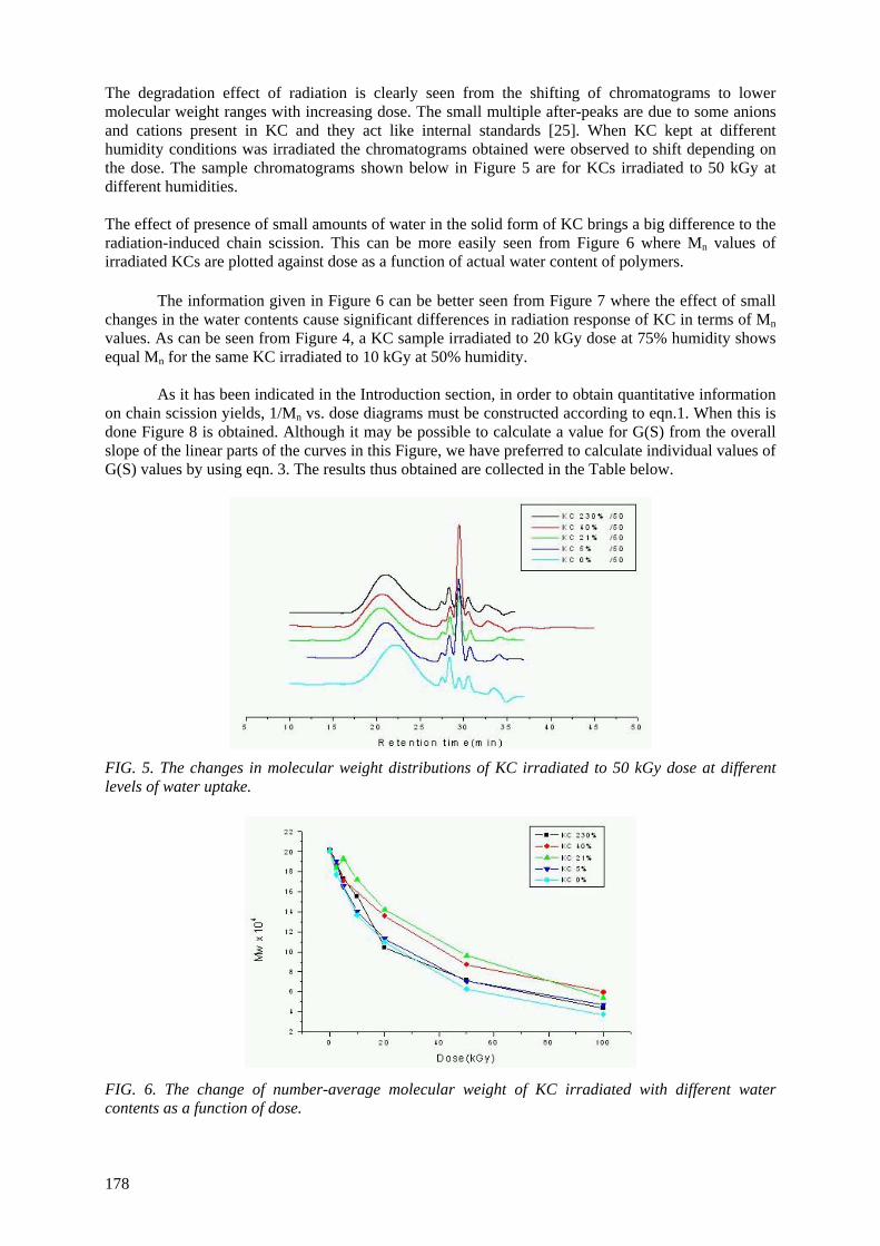
The degradation effect of radiation is clearly seen from the shifting of chromatograms to lower molecular weight ranges with increasing dose. The small multiple after-peaks are due to some anions and cations present in KC and they act like internal standards [25]. When KC kept at different humidity conditions was irradiated the chromatograms obtained were observed to shift depending on the dose. The sample chromatograms shown below in Figure 5 are for KCs irradiated to 50 kGy at different humidities. The effect of presence of small amounts of water in the solid form of KC brings a big difference to the radiation-induced chain scission. This can be more easily seen from Figure 6 where Mn values of irradiated KCs are plotted against dose as a function of actual water content of polymers.
The information given in Figure 6 can be better seen from Figure 7 where the effect of small changes in the water contents cause significant differences in radiation response of KC in terms of Mn values. As can be seen from Figure 4, a KC sample irradiated to 20 kGy dose at 75% humidity shows equal Mn for the same KC irradiated to 10 kGy at 50% humidity.
As it has been indicated in the Introduction section, in order to obtain quantitative information
on chain scission yields, 1/Mn vs. dose diagrams must be constructed according to eqn.1. When this is done Figure 8 is obtained. Although it may be possible to calculate a value for G(S) from the overall slope of the linear parts of the curves in this Figure, we have preferred to calculate individual values of G(S) values by using eqn. 3. The results thus obtained are collected in the Table below.
FIG. 5. The changes in molecular weight distributions of KC irradiated to 50 kGy dose at different levels of water uptake.
FIG. 6. The change of number-average molecular weight of KC irradiated with different water contents as a function of dose.
178
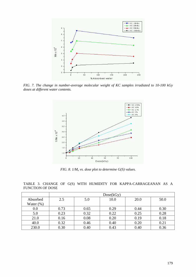
FIG. 7. The change in number-average molecular weight of KC samples irradiated to 10-100 kGy doses at different water contents.
FIG. 8. 1/Mn vs. dose plot to determine G(S) values. TABLE 3. CHANGE OF G(S) WITH HUMIDITY FOR KAPPA-CARRAGEANAN AS A FUNCTION OF DOSE
Dose(kGy) Absorbed Water (%)
2.5 5.0 10.0 20.0 50.0
0.0 0.73 0.65 0.29 0.44 0.30 5.0 0.23 0.32 0.22 0.25 0.28 21.0 0.16 0.08 0.20 0.19 0.18 40.0 0.32 0.46 0.40 0.20 0.21 230.0 0.30 0.40 0.43 0.40 0.36
179
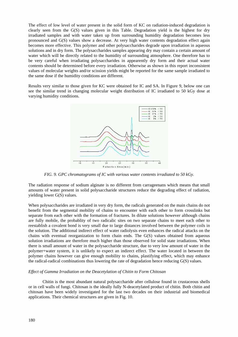
The effect of low level of water present in the solid form of KC on radiation-induced degradation is clearly seen from the G(S) values given in this Table. Degradation yield is the highest for dry irradiated samples and with water taken up from surrounding humidity degradation becomes less pronounced and G(S) values show a decrease. At very high water contents degradation effect again becomes more effective. This polymer and other polysaccharides degrade upon irradiation in aqueous solutions and in dry form. The polysaccharides samples appearing dry may contain a certain amount of water which will be directly related to the humidity of surrounding atmosphere. One therefore has to be very careful when irradiating polysaccharides in appearently dry form and their actual water contents should be determined before every irradiation. Otherwise as shown in this report inconsistent values of molecular weights and/or scission yields might be reported for the same sample irradiated to the same dose if the humidity conditions are different. Results very similar to those given for KC were obtained for IC and SA. In Figure 9, below one can see the similar trend in changing molecular weight distribution of IC irradiated to 50 kGy dose at varying humidity conditions.
FIG. 9. GPC chromatograms of IC with various water contents irradiated to 50 kGy. The radiation response of sodium alginate is no different from carrageenans which means that small amounts of water present in solid polysaccharide structures reduce the degrading effect of radiation, yielding lower G(S) values. When polysaccharides are irradiated in very dry form, the radicals generated on the main chains do not benefit from the segmental mobility of chains to encounter with each other to form crosslinks but separate from each other with the formation of fractures. In dilute solutions however although chains are fully mobile, the probablity of two radicalic sites on two separate chains to meet each other to reestablish a covalent bond is very small due to large distances involved between the polymer coils in the solution. The additional indirect effect of water radiolysis even enhances the radical attacks on the chains with eventual reorganization to form chain ends. The G(S) values obtained from aqueous solution irradiations are therefore much higher than those observed for solid state irradiations. When there is small amount of water in the polysaccharide structure, due to very low amount of water in the polymer+water system, it is unlikely to expect an indirect effect. The water located in between the polymer chains however can give enough mobility to chains, plastifying effect, which may enhance the radical-radical combinations thus lowering the rate of degradation hence reducing G(S) values. Effect of Gamma Irradiation on the Deacetylation of Chitin to Form Chitosan
Chitin is the most abundant natural polysaccharide after cellulose found in crustaceous shells or in cell walls of fungi. Chitosan is the ideally fully N-deacetylated product of chitin. Both chitin and chitosan have been widely investigated for the last two decades on their industrial and biomedical applications. Their chemical structures are given in Fig. 10.
180
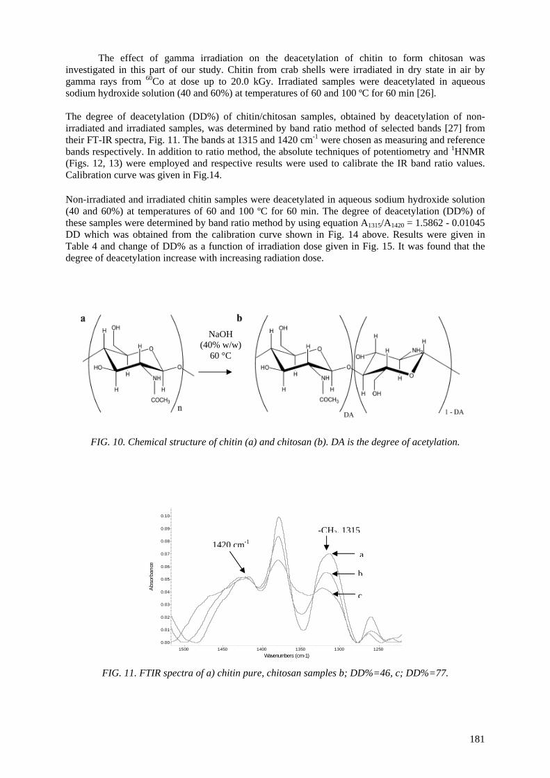
The effect of gamma irradiation on the deacetylation of chitin to form chitosan was investigated in this part of our study. Chitin from crab shells were irradiated in dry state in air by gamma rays from 60Co at dose up to 20.0 kGy. Irradiated samples were deacetylated in aqueous sodium hydroxide solution (40 and 60%) at temperatures of 60 and 100 ºC for 60 min [26].
The degree of deacetylation (DD%) of chitin/chitosan samples, obtained by deacetylation of non-irradiated and irradiated samples, was determined by band ratio method of selected bands [27] from their FT-IR spectra, Fig. 11. The bands at 1315 and 1420 cm-1 were chosen as measuring and reference bands respectively. In addition to ratio method, the absolute techniques of potentiometry and 1HNMR (Figs. 12, 13) were employed and respective results were used to calibrate the IR band ratio values. Calibration curve was given in Fig.14. Non-irradiated and irradiated chitin samples were deacetylated in aqueous sodium hydroxide solution (40 and 60%) at temperatures of 60 and 100 ºC for 60 min. The degree of deacetylation (DD%) of these samples were determined by band ratio method by using equation A1315/A1420 = 1.5862 - 0.01045 DD which was obtained from the calibration curve shown in Fig. 14 above. Results were given in Table 4 and change of DD% as a function of irradiation dose given in Fig. 15. It was found that the degree of deacetylation increase with increasing radiation dose. NaOH
(40% w/w) 60 °C
FIG. 10. Chemical structure of chitin (a) and chitosan (b). DA is the degree of acetylation.
-CH3, 13151420 cm-1
0.00
0.01
0.02
0.03
0.04
0.05
0.06
0.07
0.08
0.09
0.10
Abs
orba
nce
1250 1300 1350 1400 1450 1500 Wavenumbers (cm-1)
a
b
c
FIG. 11. FTIR spectra of a) chitin pure, chitosan samples b; DD%=46, c; DD%=77.
181
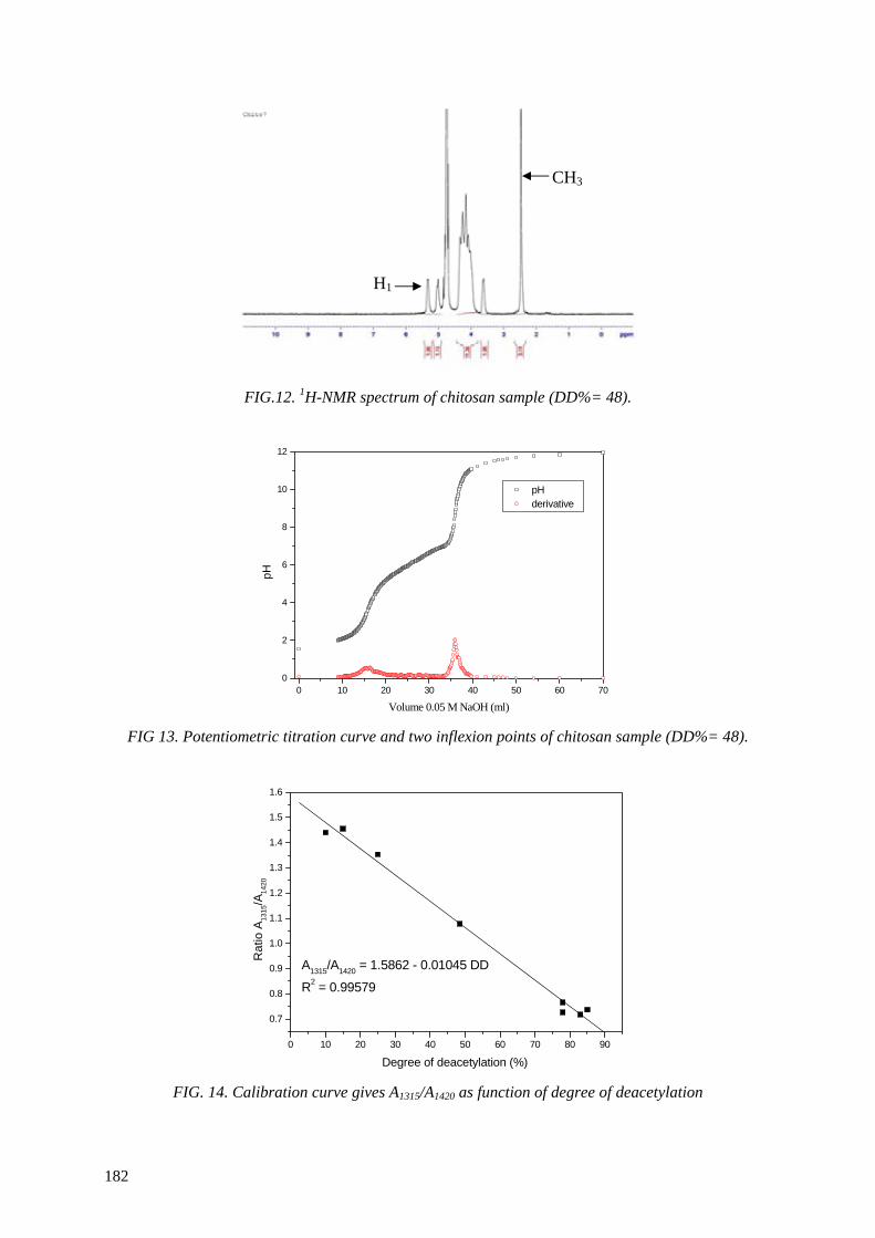
CH3
H1
FIG.12. 1H-NMR spectrum of chitosan sample (DD%= 48).
0 10 20 30 40 50 60 70
2
4
6
8
10
12
0
pH derivative
pH
Volume 0.05 M NaOH (ml) FIG 13. Potentiometric titration curve and two inflexion points of chitosan sample (DD%= 48).
0 10 20 30 40 50 60 70 80 90
0.7
0.8
0.9
1.0
1.1
1.2
1.3
1.4
1.5
1.6
A1315/A1420 = 1.5862 - 0.01045 DD
R2 = 0.99579
Rat
io A
1315
/A14
20
Degree of deacetylation (%) FIG. 14. Calibration curve gives A1315/A1420 as function of degree of deacetylation
182

0 5 10 15 2030
40
50
60
70
80
90
100
40%.60 oC. 60 min
40%.100 oC. 60 min
60%.60 oC. 60 min
60%.100 oC. 60 min
Deg
ree
of d
eace
tyla
tion
(%)
Dose (kGy)
FIG. 15. Degree of deacetylation as function irradiation dose.
TABLE 4. DOSE DEPENDENCE OF DEACETYLATION VALUES OF CHITOSAN OBTAINED FROM IRRADIATED DRY CHITIN
40%. 60 °C. 60 min
40%. 100 °C. 60 min
60%. 60 °C. 60 min
60%. 100 °C. 60 min
Dose (kGy) Average
DD% and SD CV Average
DD% and SD CV Average and
DD% and SD CV Average
DD% and SD CV
0 1.5 6 10 20
38 ± 10.5 44 ± 7 52 ± 6.8 55 ± 5.9 65 ± 11.7
0.27 0.16 0.13 0.10 0.18
72 ± 4.9 76 ± 5 80 ± 2.12 79 ± 5.65 82 ± 6.3
0.07 0.07 0.03 0.07 0.08
50 ± 8.5 52 ± 11.3 59 ± 3.5 76 ± 22 63 ± 0.7
0.16 0.21 0.06 0.29 0.01
77 ± 3,5 79 ± 2.1 86 ± 16 86 ± 4.2 90 ± 2.1
0.040.030.020.050.02
CV : Coefficient of Variation SD : Standard Deviation
The increase in DD% by irradiation can be interpreted as the results of decrease in molecular weight (in an attempt to see the change in the crystallinity of chitin by × ray diffractometry,it was not found possible to see any significant change in the × ray spectra of samples), in Table 5 results of radiation effects in molecular weight of chitin and in intrinsic viscosity are given. Molecular weight decrease with dose from 130000 to 71000 (20 kGy), this decrease is due to scission of glycoside bonds by radiation. The intrinsic viscosity was found by an ηsp/c extrapolated to infinite dilution of chitin in different dose as shown in Fig 16. The viscosity average molecular weights of irradiated chitins were determined from the relevant Mark-Houwink equation [28].
TABLE 5. MOLECULAR WEIGHT AND INTRINSIC VISCOSITY OF CHITIN AS A FUNCTION OF IRRADIATION DOSE
Dose (kGy) Intrinsic viscosity [ η] (mL/g)
Molecular weight (MW)
00 1.5 6.0 10 20
298 289 272 231 199
130000 123000 112000 88000 71000
183
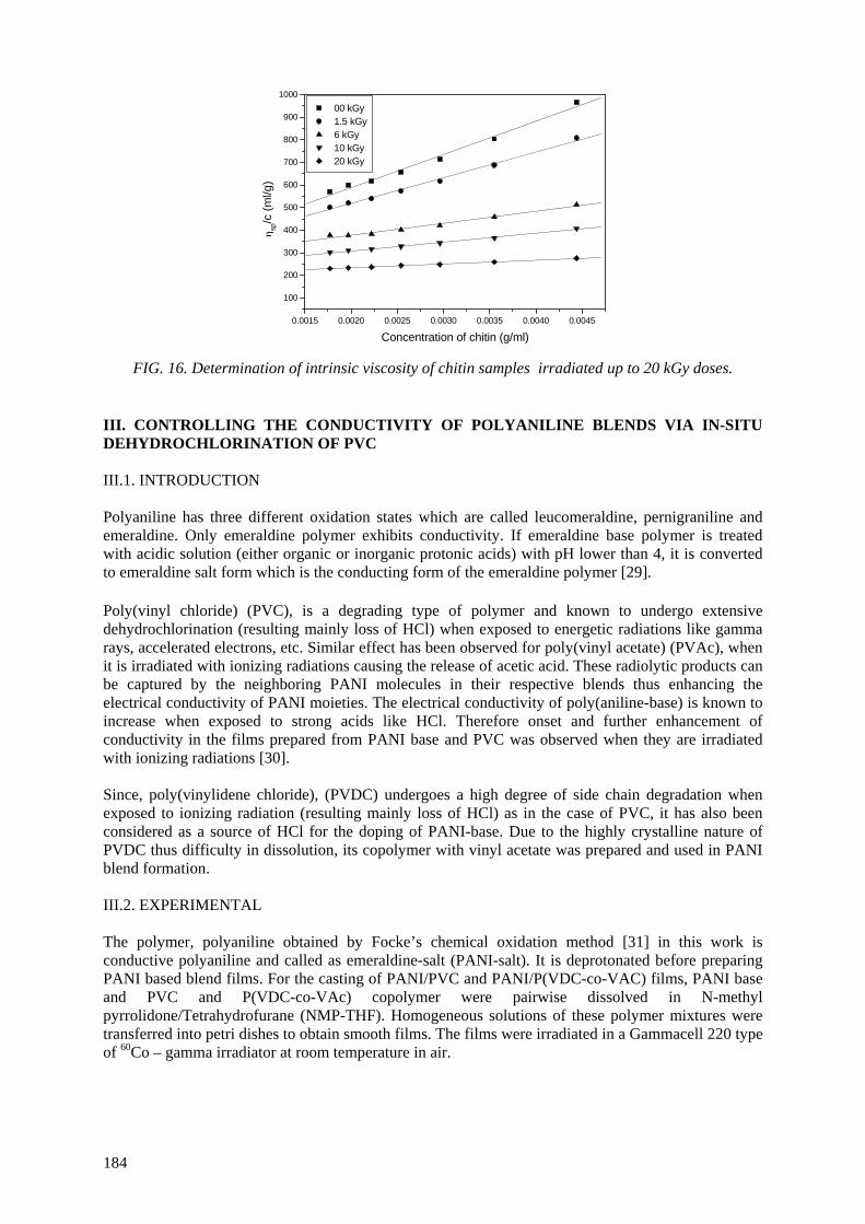
0.0015 0.0020 0.0025 0.0030 0.0035 0.0040 0.0045
100
200
300
400
500
600
700
800
900
1000 00 kGy 1.5 kGy 6 kGy 10 kGy 20 kGy
η sp/c
(ml/g
)
Concentration of chitin (g/ml)
FIG. 16. Determination of intrinsic viscosity of chitin samples irradiated up to 20 kGy doses.
III. CONTROLLING THE CONDUCTIVITY OF POLYANILINE BLENDS VIA IN-SITU DEHYDROCHLORINATION OF PVC III.1. INTRODUCTION Polyaniline has three different oxidation states which are called leucomeraldine, pernigraniline and emeraldine. Only emeraldine polymer exhibits conductivity. If emeraldine base polymer is treated with acidic solution (either organic or inorganic protonic acids) with pH lower than 4, it is converted to emeraldine salt form which is the conducting form of the emeraldine polymer [29]. Poly(vinyl chloride) (PVC), is a degrading type of polymer and known to undergo extensive dehydrochlorination (resulting mainly loss of HCl) when exposed to energetic radiations like gamma rays, accelerated electrons, etc. Similar effect has been observed for poly(vinyl acetate) (PVAc), when it is irradiated with ionizing radiations causing the release of acetic acid. These radiolytic products can be captured by the neighboring PANI molecules in their respective blends thus enhancing the electrical conductivity of PANI moieties. The electrical conductivity of poly(aniline-base) is known to increase when exposed to strong acids like HCl. Therefore onset and further enhancement of conductivity in the films prepared from PANI base and PVC was observed when they are irradiated with ionizing radiations [30]. Since, poly(vinylidene chloride), (PVDC) undergoes a high degree of side chain degradation when exposed to ionizing radiation (resulting mainly loss of HCl) as in the case of PVC, it has also been considered as a source of HCl for the doping of PANI-base. Due to the highly crystalline nature of PVDC thus difficulty in dissolution, its copolymer with vinyl acetate was prepared and used in PANI blend formation. III.2. EXPERIMENTAL The polymer, polyaniline obtained by Focke’s chemical oxidation method [31] in this work is conductive polyaniline and called as emeraldine-salt (PANI-salt). It is deprotonated before preparing PANI based blend films. For the casting of PANI/PVC and PANI/P(VDC-co-VAC) films, PANI base and PVC and P(VDC-co-VAc) copolymer were pairwise dissolved in N-methyl pyrrolidone/Tetrahydrofurane (NMP-THF). Homogeneous solutions of these polymer mixtures were transferred into petri dishes to obtain smooth films. The films were irradiated in a Gammacell 220 type of 60Co – gamma irradiator at room temperature in air.
184
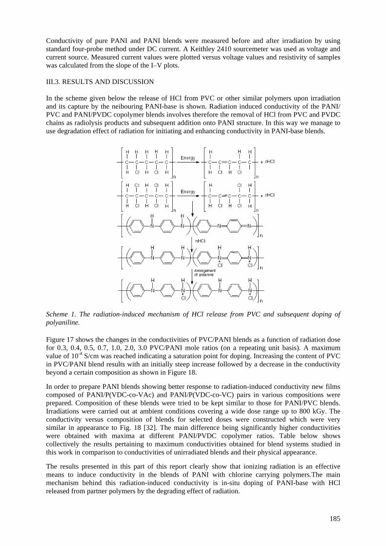
Conductivity of pure PANI and PANI blends were measured before and after irradiation by using standard four-probe method under DC current. A Keithley 2410 sourcemeter was used as voltage and current source. Measured current values were plotted versus voltage values and resistivity of samples was calculated from the slope of the I–V plots. III.3. RESULTS AND DISCUSSION In the scheme given below the release of HCl from PVC or other similar polymers upon irradiation and its capture by the neibouring PANI-base is shown. Radiation induced conductivity of the PANI/ PVC and PANI/PVDC copolymer blends involves therefore the removal of HCl from PVC and PVDC chains as radiolysis products and subsequent addition onto PANI structure. In this way we manage to use degradation effect of radiation for initiating and enhancing conductivity in PANI-base blends.
Scheme 1. The radiation-induced mechanism of HCl release from PVC and subsequent doping of polyaniline. Figure 17 shows the changes in the conductivities of PVC/PANI blends as a function of radiation dose for 0.3, 0.4, 0.5, 0.7, 1.0, 2.0, 3.0 PVC/PANI mole ratios (on a repeating unit basis). A maximum value of 10-4 S/cm was reached indicating a saturation point for doping. Increasing the content of PVC in PVC/PANI blend results with an initially steep increase followed by a decrease in the conductivity beyond a certain composition as shown in Figure 18. In order to prepare PANI blends showing better response to radiation-induced conductivity new films composed of PANI/P(VDC-co-VAc) and PANI/P(VDC-co-VC) pairs in various compositions were prepared. Composition of these blends were tried to be kept similar to those for PANI/PVC blends. Irradiations were carried out at ambient conditions covering a wide dose range up to 800 kGy. The conductivity versus composition of blends for selected doses were constructed which were very similar in appearance to Fig. 18 [32]. The main difference being significantly higher conductivities were obtained with maxima at different PANI/PVDC copolymer ratios. Table below shows collectively the results pertaining to maximum conductivities obtained for blend systems studied in this work in comparison to conductivities of unirradiated blends and their physical appearance. The results presented in this part of this report clearly show that ionizing radiation is an effective means to induce conductivity in the blends of PANI with chlorine carrying polymers.The main mechanism behind this radiation-induced conductivity is in-situ doping of PANI-base with HCl released from partner polymers by the degrading effect of radiation.
185
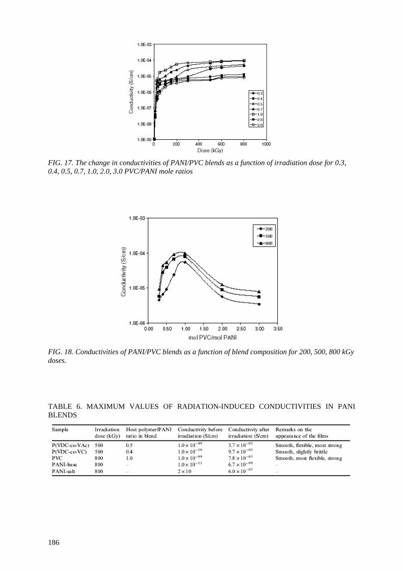
FIG. 17. The change in conductivities of PANI/PVC blends as a function of irradiation dose for 0.3, 0.4, 0.5, 0.7, 1.0, 2.0, 3.0 PVC/PANI mole ratios
FIG. 18. Conductivities of PANI/PVC blends as a function of blend composition for 200, 500, 800 kGy doses. TABLE 6. MAXIMUM VALUES OF RADIATION-INDUCED CONDUCTIVITIES IN PANI BLENDS
186

REFERENCES [1] BURILLO, G., CLOUGH, R., CZVIKOVSZKY, T., GÜVEN, O., LE MOEL, A., LIU, W.,
SINGH, YANG, A.J., ZAHARESCU, T., Radiation Phys. and Chem. 64 (2001) 41. [2] ADHIKARI, B., DE, D., MAITI, S., Prog. Polym. Sci. 25, (2000) 909. [3] SHARMA, V.K., FORTUNA, F., MINCARINI, M., BERILLO, M., CORNACCHIA, G.,
Applied Energy 65 (2000) 381. [4] FANG, Y., ZHAN, M., WANG, Y., Materials and Design 22 (2001) 123. [5] PUSKAS, J.E., HUTCHINSON, R., Rubber and Techn., 66 (1993) 742. [6] YANG, J., et.al.“Radiation recycling of butyl rubber wastes” in Environmental application of
ionizing radiation"(edited by R. D. COOPER and K. E. O’SHEA), Wiley, New York, (1988) 601.
[7] JIPA, S., GIURGINCA, M., SETNESCU, T., SETNESCU, R., IVAN, G., MIHALCEA, I., Polymer Degradation and Stability, 54 (1996) 1.
[8] SCHNABEL, W., "High energy radiation- and UV light –induced crosslinking and chain Scission" in “Cross-linking and Scission in Polymers” O .GÜVEN Ed., NATO ASI Series, Kluwer Academic Publishers, The Netherlands (1988) 15.
[9] WARNER, W.C., Rubber Chem. Technol., 67 (1994) 559. [10] CAPELLE, G., BERSTORFF, H., Tire Technol. Int., Annual Review (1997) 278. [11] ISAYEV, A.I., CHEN, J., TUKACHINSKY, A., Rubber Chem. Technol., 68 (1995) 267. [12] ADHIKARI, B., DE, D., MAITI, S., Prog. Poly. Sci., 25 (2000) 909. [13] ZAHARESCU, T., POSTOLACHE, C., GIURGINCA, M., J. Appl. Poly. Sci., 59 (1996) 969. [14] FENG, W., ISAYEV, A.I., J. Mater. Sci., 40 (2005) 2883. [15] SOMBATSOMPOP, N., KUMNUANTIP, C., J. Appl. Poly. Sci., 87 (2003) 1723. [16] ZAHARESCU, T., CAZAC, C., JIPA, S., SETNESCU, R., Nucl.Instr.and Meth B, 185 (2001)
360. [17] SEN, M., UZUN, C., KANTOĞLU, Ö., ERDOĞAN, S.M., DENIZ, V., GÜVEN, O., Nucl.
Instr. and Meth B, 208 (2003) 480. [18] TELNOV, A.V., ZAVYALOVA, N.V., YU, KHOKHLOVA, A., SITNIKOVA, N.P.
,SMETANINA, M.L., TARANTASOVA, V.P., SHADRINA, D.N., SHORIKOVA, I.V., LIAKUMOVICHB, A.L., MIRYASOVAB, F.K., Radiat. Phys. Chem., 63 (2002) 245
[19] CHARLESBY, A., “Atomic Radiation and Polymers” Pergamon Pres, New York 1960. [20] CHOI, W-S., AHN, K.-J., LEE, D.-W., BYUN, M.W., PARK, H.J., Polym. Deg. Stab., 78
(2002) 533-538. [21] WASIKIEWICZ, J.M., YOSHII, F., NAGASAWA, N., WACH, R.A., MITOMO, H., Rad.
Phys. Chem., 73 (2005) 287-295. [22] RELLEVE, L., NAGASAWA, N., LUAN, L.Q., YAGI, T., ARANILLA, C., ABAD, L.,
KUME, T., YOSHII, F. DELA ROSA, A., Polym. Deg. Stab., 87 (2005) 403-410. [23] NAGASAWA, N., MITOMO, H., YOSHII, F., KUME, T., Polym. Deg. Stab., 69 (2000) 279-
285. [24] YOSHII, F., ZHAO, L., WACH, R.A., NAGASAWA, N., MITOMO, H., KUME, T., Nuclear
Inst. Met. Phys. Res.B, 208 (2003) 320-324. [25] ALTUNTAS, E., SEN, M., GÜVEN, O., to be published (2008). [26] METHACANON, P., PRATILTSIP, M., POTHSREE, T., PATTARAARCHACHAI, J.,
Carbohydrate Polymers, 52 (2003) 119-123. [27] BRUGNEROTTO, J., LIZARDI, J., GOYCOOLEA, F.M., ARGÜELLES-MONAL, W.,
DESBRIERES, J., RINAUDO, M., Polymer, 42 (2001) 3569-3580. [28] EINBU, A., NAESS, S.N., ELGSAETER, A., VARUM, K.M., Biomacromolecules, 5 (2004)
2048-2054. [29] CHIANG, C.K., MacDIARMID, A.G., Synthetic Metals, 13 (1986)193-198. [30] BODUGOZ, H., SEVIL, U.A., GÜVEN, O., Macromol. Symposia, 169 (1998) 89-94. [31] FOCKE, W.W., WNEK, G.E., WEI, Y., J. Phys. Chem., 91 (1987) 5813-5817. [32] BODUGOZ, H., GÜVEN, O., Nuclear Inst. Met. Phys. Res.B, 236 (2005)153-159.
187

INSIGHTS INTO OXIDATION MECHANISMS IN GAMMA IRRADIATED POLYPROPYLENE, UTILIZING SELECTIVE ISOTOPIC LABELING WITH ANALYSIS BY GC/MS, NMR AND FTIR
R. BERNSTEIN, S.M. THORNBERG, R.A. ASSINK, D.M. MOWERY†, M.K. ALAM, A.N. IRWIN, J.M. HOCHREIN, D.K. DERZON, S.B. KLAMO*‡, R.L. CLOUGH Organic Materials Department, Sandia National Laboratories, Albuquerque, NM, USA †Arnold and Mabel Beckman Laboratories of Chemical Synthesis California Institute of Technology Pasadena, CA, USA †Current address: Dow Chemical, Analytical Sciences, Freeport, TX 77541 ‡ Current address: Dow Chemical, 1776 Building, Midland, MI 48674
Abstract
In an effort to shed additional light on the chemical mechanisms underlying the radiation-oxidation of polypropylene, we are using samples having selective C-13 isotopic labeling at the three unique sites within the macromolecular structure. After radiation exposure, we applied gas chromatography/mass spectroscopy (GC/MS), solid-state C-13 NMR, and FTIR to evaluate the applicability of each technique in identifying the molecular labeling of the oxidation products, with the goal of determining the site of origin of the products with respect to the macromolecule. Using GC/MS, we have identified the position of origin of CO2 and CO from the polymer. Most of the CO2 (60%) and CO (> 90%) come from the C(1) (methylene) position of polypropylene, with (30%) of the CO2 originating from the C(3) (methyl) position, and 10% coming from the C(2) (tertiary) position. By GC/MS we have also identified the labeling patterns in four volatile oxidation products (acetone, methylisobutylketone, isobutane, and methyl acetate), and have used this information to map each compound onto the macromolecular framework. Using NMR we have been able to identify and quantify the time-dependent formation of solid-phase degradation products occurring from post-irradiation aging of polypropylene samples held for 28 months at room temperature in air. Most of the solid oxidation products occur at the C(2) (tertiary) site; the predominant species, C(2) peroxides, increase linearly during about the first 2 years, after which they plateau at a relatively high concentration.
1. INTRODUCTION
Most applications that combine polymers and radiation, involve exposure to atmospheric oxygen during and/or subsequent to the radiation exposure. The effects of the radiation are frequently dominated by the participation of oxygen.[1-4] Free radical chemistry is typically the primary pathway[2,5] among possible oxidation routes.[6,7] In some cases, the controlled degradation of a polymer is the desired result.[8] For example, reduced molecular weight and particle size, as well as increased compatibility with other substances, is the basis of radiation processing of tetrafluoroethylene in the presence of air to produce an additive in inks and lubricants. Irradiation of raw polypropylene resin to alter molecular weight distribution and thereby enhance melt-flow characteristics, is a growing industrial process. Controlled degradation is the subject of research for a variety of other potential applications, including alteration of surface characteristics for enhanced adhesion, recycling, treatment of natural products such as cellulose, etc.[8,9]
In other processing applications, oxidation is an unwanted byproduct of radiation treatment, and the objective is to suppress oxidation as much as possible, for example through selection of processing conditions, post-irradiation treatment such as annealing, incorporation of additives to minimize radiation-oxidation, etc.[2,4,10] Examples include radiation sterilization of disposable medical items such as polypropylene syringes, radiation treatment of ultra high molecular weight polyethylene to enhance wear properties, and numerous crosslinking and curing applications such as production of high-performance cable insulation.[4] In many cases, slow post-irradiation reaction with oxygen in the ambient environment can be a dominant factor in long-term performance.[2,5] Peroxides and radicals formed in the polymer during irradiation can lead to further oxidation
189
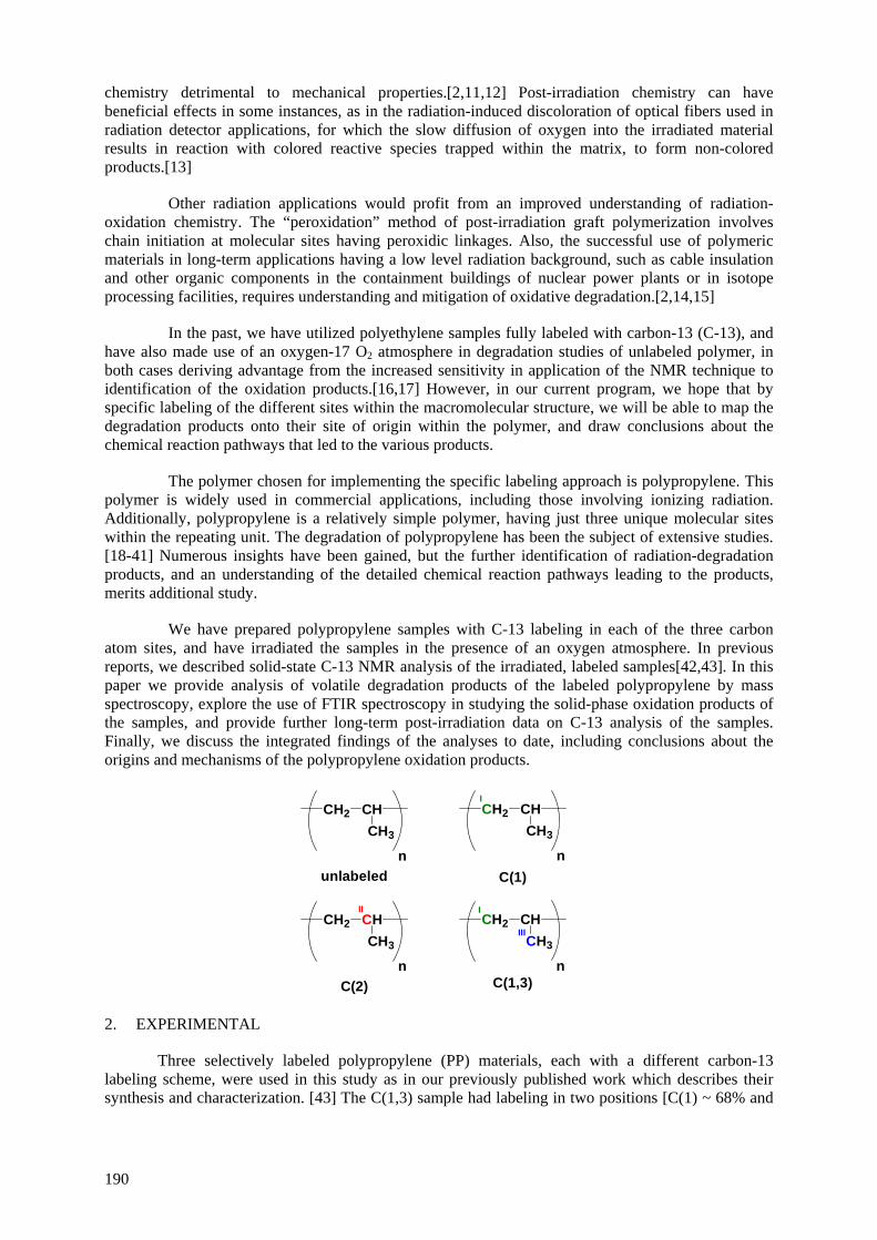
chemistry detrimental to mechanical properties.[2,11,12] Post-irradiation chemistry can have beneficial effects in some instances, as in the radiation-induced discoloration of optical fibers used in radiation detector applications, for which the slow diffusion of oxygen into the irradiated material results in reaction with colored reactive species trapped within the matrix, to form non-colored products.[13]
Other radiation applications would profit from an improved understanding of radiation-oxidation chemistry. The “peroxidation” method of post-irradiation graft polymerization involves chain initiation at molecular sites having peroxidic linkages. Also, the successful use of polymeric materials in long-term applications having a low level radiation background, such as cable insulation and other organic components in the containment buildings of nuclear power plants or in isotope processing facilities, requires understanding and mitigation of oxidative degradation.[2,14,15]
In the past, we have utilized polyethylene samples fully labeled with carbon-13 (C-13), and have also made use of an oxygen-17 O2 atmosphere in degradation studies of unlabeled polymer, in both cases deriving advantage from the increased sensitivity in application of the NMR technique to identification of the oxidation products.[16,17] However, in our current program, we hope that by specific labeling of the different sites within the macromolecular structure, we will be able to map the degradation products onto their site of origin within the polymer, and draw conclusions about the chemical reaction pathways that led to the various products.
The polymer chosen for implementing the specific labeling approach is polypropylene. This polymer is widely used in commercial applications, including those involving ionizing radiation. Additionally, polypropylene is a relatively simple polymer, having just three unique molecular sites within the repeating unit. The degradation of polypropylene has been the subject of extensive studies. [18-41] Numerous insights have been gained, but the further identification of radiation-degradation products, and an understanding of the detailed chemical reaction pathways leading to the products, merits additional study.
We have prepared polypropylene samples with C-13 labeling in each of the three carbon atom sites, and have irradiated the samples in the presence of an oxygen atmosphere. In previous reports, we described solid-state C-13 NMR analysis of the irradiated, labeled samples[42,43]. In this paper we provide analysis of volatile degradation products of the labeled polypropylene by mass spectroscopy, explore the use of FTIR spectroscopy in studying the solid-phase oxidation products of the samples, and provide further long-term post-irradiation data on C-13 analysis of the samples. Finally, we discuss the integrated findings of the analyses to date, including conclusions about the origins and mechanisms of the polypropylene oxidation products.
CH2 CHCH3
n
CH2 CHII
CH3
n
CH2 CHCH3
n
CH2 CHCH3
n
unlabeled C(1)
C(2) C(1,3)
I
III
I
2. EXPERIMENTAL
Three selectively labeled polypropylene (PP) materials, each with a different carbon-13 labeling scheme, were used in this study as in our previously published work which describes their synthesis and characterization. [43] The C(1,3) sample had labeling in two positions [C(1) ~ 68% and
190
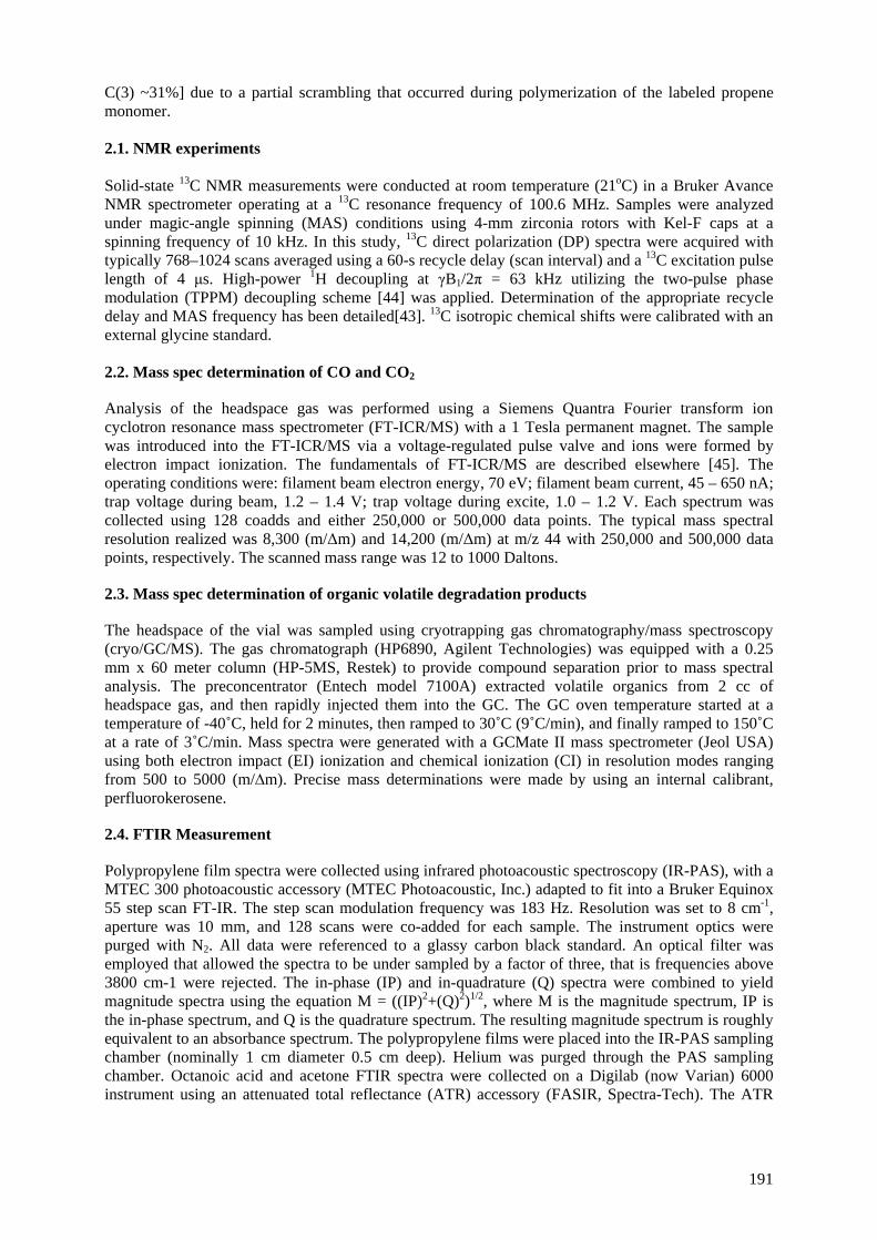
C(3) ~31%] due to a partial scrambling that occurred during polymerization of the labeled propene monomer. 2.1. NMR experiments Solid-state 13C NMR measurements were conducted at room temperature (21oC) in a Bruker Avance NMR spectrometer operating at a 13C resonance frequency of 100.6 MHz. Samples were analyzed under magic-angle spinning (MAS) conditions using 4-mm zirconia rotors with Kel-F caps at a spinning frequency of 10 kHz. In this study, 13C direct polarization (DP) spectra were acquired with typically 768–1024 scans averaged using a 60-s recycle delay (scan interval) and a 13C excitation pulse length of 4 μs. High-power 1H decoupling at γB1/2π = 63 kHz utilizing the two-pulse phase modulation (TPPM) decoupling scheme [44] was applied. Determination of the appropriate recycle delay and MAS frequency has been detailed[43]. 13C isotropic chemical shifts were calibrated with an external glycine standard. 2.2. Mass spec determination of CO and CO2
Analysis of the headspace gas was performed using a Siemens Quantra Fourier transform ion cyclotron resonance mass spectrometer (FT-ICR/MS) with a 1 Tesla permanent magnet. The sample was introduced into the FT-ICR/MS via a voltage-regulated pulse valve and ions were formed by electron impact ionization. The fundamentals of FT-ICR/MS are described elsewhere [45]. The operating conditions were: filament beam electron energy, 70 eV; filament beam current, 45 – 650 nA; trap voltage during beam, 1.2 – 1.4 V; trap voltage during excite, 1.0 – 1.2 V. Each spectrum was collected using 128 coadds and either 250,000 or 500,000 data points. The typical mass spectral resolution realized was 8,300 (m/Δm) and 14,200 (m/Δm) at m/z 44 with 250,000 and 500,000 data points, respectively. The scanned mass range was 12 to 1000 Daltons.
2.3. Mass spec determination of organic volatile degradation products
The headspace of the vial was sampled using cryotrapping gas chromatography/mass spectroscopy (cryo/GC/MS). The gas chromatograph (HP6890, Agilent Technologies) was equipped with a 0.25 mm x 60 meter column (HP-5MS, Restek) to provide compound separation prior to mass spectral analysis. The preconcentrator (Entech model 7100A) extracted volatile organics from 2 cc of headspace gas, and then rapidly injected them into the GC. The GC oven temperature started at a temperature of -40˚C, held for 2 minutes, then ramped to 30˚C (9˚C/min), and finally ramped to 150˚C at a rate of 3˚C/min. Mass spectra were generated with a GCMate II mass spectrometer (Jeol USA) using both electron impact (EI) ionization and chemical ionization (CI) in resolution modes ranging from 500 to 5000 (m/∆m). Precise mass determinations were made by using an internal calibrant, perfluorokerosene.
2.4. FTIR Measurement
Polypropylene film spectra were collected using infrared photoacoustic spectroscopy (IR-PAS), with a MTEC 300 photoacoustic accessory (MTEC Photoacoustic, Inc.) adapted to fit into a Bruker Equinox 55 step scan FT-IR. The step scan modulation frequency was 183 Hz. Resolution was set to 8 cm-1, aperture was 10 mm, and 128 scans were co-added for each sample. The instrument optics were purged with N2. All data were referenced to a glassy carbon black standard. An optical filter was employed that allowed the spectra to be under sampled by a factor of three, that is frequencies above 3800 cm-1 were rejected. The in-phase (IP) and in-quadrature (Q) spectra were combined to yield magnitude spectra using the equation M = ((IP)2+(Q)2)1/2, where M is the magnitude spectrum, IP is the in-phase spectrum, and Q is the quadrature spectrum. The resulting magnitude spectrum is roughly equivalent to an absorbance spectrum. The polypropylene films were placed into the IR-PAS sampling chamber (nominally 1 cm diameter 0.5 cm deep). Helium was purged through the PAS sampling chamber. Octanoic acid and acetone FTIR spectra were collected on a Digilab (now Varian) 6000 instrument using an attenuated total reflectance (ATR) accessory (FASIR, Spectra-Tech). The ATR
191
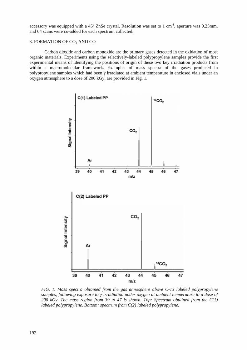
accessory was equipped with a 45o ZnSe crystal. Resolution was set to 1 cm-1, aperture was 0.25mm, and 64 scans were co-added for each spectrum collected.
3. FORMATION OF CO2 AND CO
Carbon dioxide and carbon monoxide are the primary gases detected in the oxidation of most organic materials. Experiments using the selectively-labeled polypropylene samples provide the first experimental means of identifying the positions of origin of these two key irradiation products from within a macromolecular framework. Examples of mass spectra of the gases produced in polypropylene samples which had been γ irradiated at ambient temperature in enclosed vials under an oxygen atmosphere to a dose of 200 kGy, are provided in Fig. 1.
FIG. 1. Mass spectra obtained from the gas atmosphere above C-13 labeled polypropylene samples, following exposure to γ-irradiation under oxygen at ambient temperature to a dose of 200 kGy. The mass region from 39 to 47 is shown. Top: Spectrum obtained from the C(1) labeled polypropylene. Bottom: spectrum from C(2) labeled polypropylene.
192
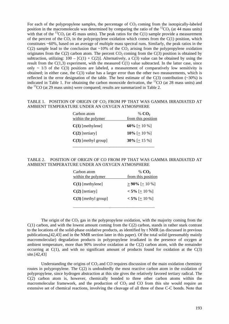
For each of the polypropylene samples, the percentage of CO2 coming from the isotopically-labeled position in the macromolecule was determined by comparing the ratio of the 12CO2 (at 44 mass units) with that of the 13CO2 (at 45 mass units). The peak ratios for the C(1) sample provide a measurement of the percent of the CO2 in the polypropylene oxidation which comes from the C(1) position, which constitutes ~60%, based on an average of multiple mass spectral runs. Similarly, the peak ratios in the C(2) sample lead to the conclusion that ~10% of the CO2 arising from the polypropylene oxidation originates from the C(2) carbon atom. The percent CO2 coming from the C(3) position is obtained by subtraction, utilizing: 100 – [C(1) + C(2)]. Alternatively, a C(3) value can be obtained by using the result from the C(1,3) experiment, with the measured C(1) value subtracted. In the latter case, since only ~ 1/3 of the C(3) positions are labeled, a measurement of comparatively low sensitivity is obtained; in either case, the C(3) value has a larger error than the other two measurements, which is reflected in the error designation of the table. The best estimate of the C(3) contribution (~30%) is indicated in Table 1. For obtaining the carbon monoxide derivation, the 12CO (at 28 mass units) and the 13CO (at 29 mass units) were compared; results are summarized in Table 2.
TABLE 1. POSITION OF ORIGIN OF CO2 FROM PP THAT WAS GAMMA IRRADIATED AT AMBIENT TEMPERATURE UNDER AN OXYGEN ATMOSPHERE
Carbon atom % CO2 within the polymer from this position
C(1) [methylene] 60% [+ 10 %]
C(2) [tertiary] 10% [+ 10 %]
C(3) [methyl group] 30% [+ 15 %] _________________ _____________________
TABLE 2. POSITION OF ORIGIN OF CO FROM PP THAT WAS GAMMA IRRADIATED AT AMBIENT TEMPERATURE UNDER AN OXYGEN ATMOSPHERE
Carbon atom % CO2 within the polymer from this position
C(1) [methylene] > 90% [+ 10 %]
C(2) [tertiary] < 5% [+ 10 %]
C(3) [methyl group] < 5% [+ 10 %]
_________________ _____________________
The origin of the CO2 gas in the polypropylene oxidation, with the majority coming from the C(1) carbon, and with the lowest amount coming from the C(2) carbon, stands in rather stark contrast to the locations of the solid-phase oxidative products, as identified by t NMR (as discussed in previous publications,[42,43] and in the NMR section later in this paper). Of the total solid (presumably mainly macromolecular) degradation products in polypropylene irradiated in the presence of oxygen at ambient temperature, more than 90% involve oxidation at the C(2) carbon atom, with the remainder occurring at C(1), and with no significant amount of products found for oxidation at the C(3) site.[42,43]
Understanding the origins of CO2 and CO requires discussion of the main oxidation chemistry routes in polypropylene. The C(2) is undoubtedly the most reactive carbon atom in the oxidation of polypropylene, since hydrogen abstraction at this site gives the relatively favored tertiary radical. The C(2) carbon atom is, however, chemically bonded to three other carbon atoms within the macromolecular framework, and the production of CO2 and CO from this site would require an extensive set of chemical reactions, involving the cleavage of all three of these C-C bonds. Note that
193
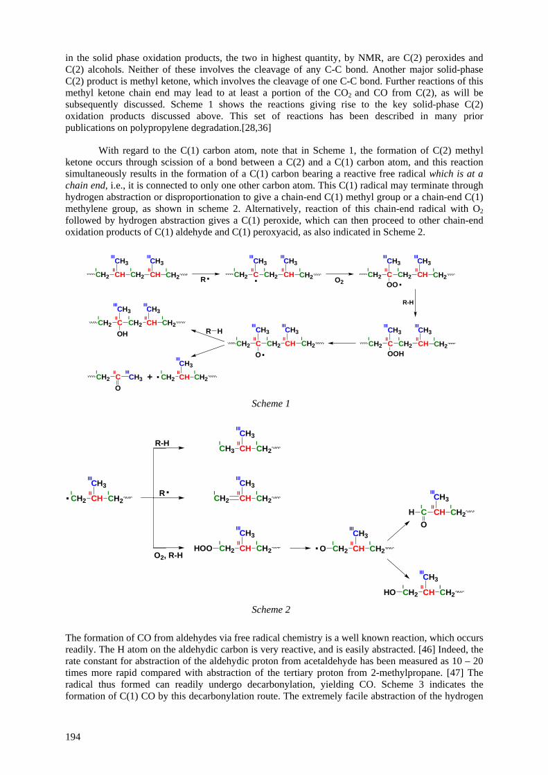
in the solid phase oxidation products, the two in highest quantity, by NMR, are C(2) peroxides and C(2) alcohols. Neither of these involves the cleavage of any C-C bond. Another major solid-phase C(2) product is methyl ketone, which involves the cleavage of one C-C bond. Further reactions of this methyl ketone chain end may lead to at least a portion of the CO2 and CO from C(2), as will be subsequently discussed. Scheme 1 shows the reactions giving rise to the key solid-phase C(2) oxidation products discussed above. This set of reactions has been described in many prior publications on polypropylene degradation.[28,36]
With regard to the C(1) carbon atom, note that in Scheme 1, the formation of C(2) methyl ketone occurs through scission of a bond between a C(2) and a C(1) carbon atom, and this reaction simultaneously results in the formation of a C(1) carbon bearing a reactive free radical which is at a chain end, i.e., it is connected to only one other carbon atom. This C(1) radical may terminate through hydrogen abstraction or disproportionation to give a chain-end C(1) methyl group or a chain-end C(1) methylene group, as shown in scheme 2. Alternatively, reaction of this chain-end radical with O2 followed by hydrogen abstraction gives a C(1) peroxide, which can then proceed to other chain-end oxidation products of C(1) aldehyde and C(1) peroxyacid, as also indicated in Scheme 2.
CH2 CH CHIIII
C CHIIII
. C CHIIII
C CHIIII
C CHIIII
C CHIIII
CII
CHII
CH3
CH2
CH3III
I I
III
CH2I
R. CH2
CH3
CH2
CH3III
I I
III
CH2I
O2CH2
CH3
CH2
CH3III
I I
III
CH2I
.OO
R-H
CH2
CH3
CH2
CH3III
I I
III
CH2I
OOHCH2
CH3
CH2
O
CH3III
I I
III
.
CH2
CH3
CH2OH
CH3III
I I
III
CH2 CH3O
IIIICH2
CH3I
III
.+
R HCH2I
CH2I
CH2I
Scheme 1
CH2 CHII
CHII
CHII
CHII
CHII
CHII
CHII
CH3I
III
. CH2I
R-H
R.
O2, R-H
CH3
CH3I
III
CH2I
CH2
CH3I
III
CH2I
CH2
CH3I
III
CH2I
HOO CH2
CH3I
III
CH2I
O.
CH2
CH3I
III
CH2I
HO
C
CH3I
III
CH2I
HO
Scheme 2
The formation of CO from aldehydes via free radical chemistry is a well known reaction, which occurs readily. The H atom on the aldehydic carbon is very reactive, and is easily abstracted. [46] Indeed, the rate constant for abstraction of the aldehydic proton from acetaldehyde has been measured as 10 – 20 times more rapid compared with abstraction of the tertiary proton from 2-methylpropane. [47] The radical thus formed can readily undergo decarbonylation, yielding CO. Scheme 3 indicates the formation of C(1) CO by this decarbonylation route. The extremely facile abstraction of the hydrogen
194
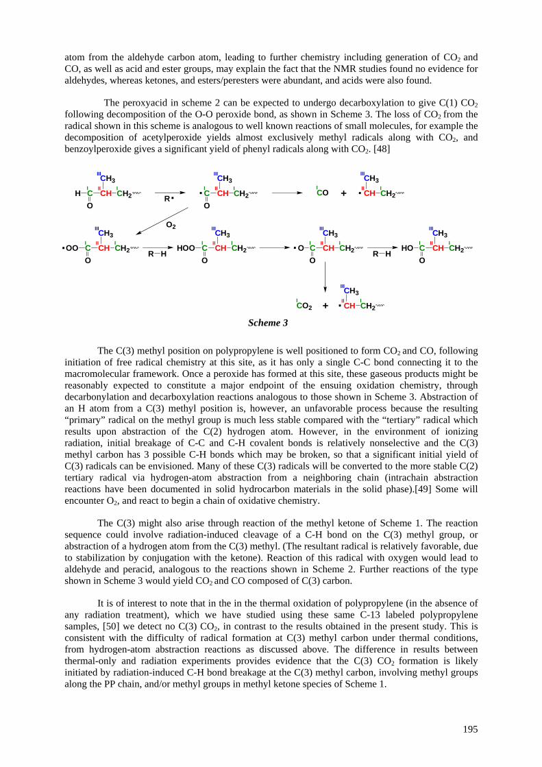
atom from the aldehyde carbon atom, leading to further chemistry including generation of CO2 and CO, as well as acid and ester groups, may explain the fact that the NMR studies found no evidence for aldehydes, whereas ketones, and esters/peresters were abundant, and acids were also found.
The peroxyacid in scheme 2 can be expected to undergo decarboxylation to give C(1) CO2 following decomposition of the O-O peroxide bond, as shown in Scheme 3. The loss of CO2 from the radical shown in this scheme is analogous to well known reactions of small molecules, for example the decomposition of acetylperoxide yields almost exclusively methyl radicals along with CO2, and benzoylperoxide gives a significant yield of phenyl radicals along with CO2. [48]
C CHII
CHII
CHII
CHII
CHII
CHII
CHII
CHII
CH3I
III
CH2I
OH .
R. C
CH3I
III
CH2I
O
.CO
CH3I
III
CH2I+
O2
C
CH3I
III
CH2I
OOO.
R HC
CH3I
III
CH2I
OHOO C
CH3I
III
CH2I
OO.
R HC
CH3I
III
CH2I
OHO
.CO2
CH3I
III
CH2I+
Scheme 3
The C(3) methyl position on polypropylene is well positioned to form CO2 and CO, following initiation of free radical chemistry at this site, as it has only a single C-C bond connecting it to the macromolecular framework. Once a peroxide has formed at this site, these gaseous products might be reasonably expected to constitute a major endpoint of the ensuing oxidation chemistry, through decarbonylation and decarboxylation reactions analogous to those shown in Scheme 3. Abstraction of an H atom from a C(3) methyl position is, however, an unfavorable process because the resulting “primary” radical on the methyl group is much less stable compared with the “tertiary” radical which results upon abstraction of the C(2) hydrogen atom. However, in the environment of ionizing radiation, initial breakage of C-C and C-H covalent bonds is relatively nonselective and the C(3) methyl carbon has 3 possible C-H bonds which may be broken, so that a significant initial yield of C(3) radicals can be envisioned. Many of these C(3) radicals will be converted to the more stable C(2) tertiary radical via hydrogen-atom abstraction from a neighboring chain (intrachain abstraction reactions have been documented in solid hydrocarbon materials in the solid phase).[49] Some will encounter O2, and react to begin a chain of oxidative chemistry.
The C(3) might also arise through reaction of the methyl ketone of Scheme 1. The reaction sequence could involve radiation-induced cleavage of a C-H bond on the C(3) methyl group, or abstraction of a hydrogen atom from the C(3) methyl. (The resultant radical is relatively favorable, due to stabilization by conjugation with the ketone). Reaction of this radical with oxygen would lead to aldehyde and peracid, analogous to the reactions shown in Scheme 2. Further reactions of the type shown in Scheme 3 would yield CO2 and CO composed of C(3) carbon.
It is of interest to note that in the in the thermal oxidation of polypropylene (in the absence of any radiation treatment), which we have studied using these same C-13 labeled polypropylene samples, [50] we detect no C(3) CO2, in contrast to the results obtained in the present study. This is consistent with the difficulty of radical formation at C(3) methyl carbon under thermal conditions, from hydrogen-atom abstraction reactions as discussed above. The difference in results between thermal-only and radiation experiments provides evidence that the C(3) CO2 formation is likely initiated by radiation-induced C-H bond breakage at the C(3) methyl carbon, involving methyl groups along the PP chain, and/or methyl groups in methyl ketone species of Scheme 1.
195
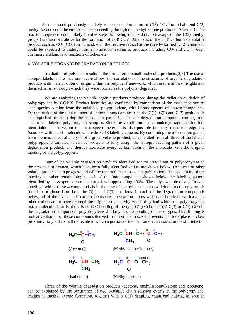
As mentioned previously, a likely route to the formation of C(2) CO2 from chain-end C(2) methyl ketone could be envisioned as proceeding through the methyl ketone product of Scheme 1. The reaction sequence could likely involve steps following the oxidative cleavage of the C(3) methyl group, (as described above for the formation of C(3) CO2). After loss of the C(3) carbon as a volatile product such as CO2, CO, formic acid, etc., the reactive radical at the (newly-formed) C(2) chain end could be expected to undergo further oxidation leading to products including CO2 and CO through chemistry analogous to reactions of Scheme 2.
4. VOLATILE ORGANIC DEGRADATION PRODUCTS
Irradiation of polymers results in the formation of small molecular products.[2,5] The use of isotopic labels in the macromolecule allows the correlation of the structures of organic degradation products with their position of origin within the polymer framework, which in turn allows insights into the mechanisms through which they were formed as the polymer degraded.
We are analyzing the volatile organic products produced during the radiation-oxidation of polypropylene by GC/MS. Product identities are confirmed by comparison of the mass spectrum of each species coming from the unlabeled polypropylene, with library spectra of known compounds. Determination of the total number of carbon atoms coming from the C(1), C(2) and C(3) positions is accomplished by measuring the mass of the parent ion for each degradation compound coming from each of the labeled polypropylene samples. Since the volatile molecules undergo fragmentation into identifiable pieces within the mass spectrometer, it is also possible in many cases to assign the locations within each molecule where the C-13 labeling appears. By combining the information gained from the mass spectral analysis of a given volatile product, as generated from all three of the labeled polypropylene samples, it can be possible to fully assign the isotopic labeling pattern of a given degradation product, and thereby correlate every carbon atom in the molecule with the original labeling of the polypropylene.
Four of the volatile degradation products identified for the irradiation of polypropylene in the presence of oxygen, which have been fully identified so far, are shown below. (Analysis of other volatile products is in progress and will be reported in a subsequent publication). The specificity of the labeling is rather remarkable; in each of the four compounds shown below, the labeling pattern identified by mass spec is consistent at a level approaching 100%. The only example of any “mixed labeling” within these 4 compounds is in the case of methyl acetate, for which the methoxy group is found to originate from both the C(1) and C(3) positions. In each of the degradation compounds below, all of the “catenated” carbon atoms (i.e., the carbon atoms which are bonded to at least one other carbon atom) have retained the original connectivity which they had within the polypropylene macromolecule. That is, there is no C-C bonding of the type C(1)-C(1), or C(3)-C(3) or C(1)-C(3) in the degradation compounds; polypropylene similarly has no bonding of these types. This finding is indicative that all of these compounds derived from two chain scission events that took place in close proximity, to yield a small molecule in which a portion of the macromolecular structure is still intact.
H3C CII
CH3
O
IIII
CH3
CH CIIII
CH2
OCH3
I III
IIIH3C
I
(Acetone) (Methylisobutylketone)
H3C CHII
CH3IIII
CH3I
OCII
H3CO
IIICH3
I and III
(Isobutane) (Methyl acetate)
Three of the volatile degradation products (acetone, methylisobutylketone and isobutene) can be explained by the occurrence of two oxidative chain scission events in the polypropylene, leading to methyl ketone formation, together with a C(1) dangling chain end radical, as seen in
196

Scheme 1. Alternatively, the acetone and methylisobutylketone could be formed through a combination of one oxidative chain scission event (giving the methyl ketone), together with one simple radiation-induced C-C bond cleavage between a C(1) and a C(2) carbon within the chain. The isobutane could be the result of either of the two possibilities mentioned above, or could also result from two direct radiation-induced chain scission events. Obviously, each product could result from a combination of the possibilities indicated here. In any event, the formation of a C(1) methyl group in any of these three molecules would be the result of a C(1) radical, [having formed by scission of the C-C bond to its adjacent C(2) atom within the chain] subsequently undergoing a hydrogen abstraction reaction from a neighboring chain (similar to one of the outcomes of Scheme 2). Scheme 4 shows a route to the formation of these three compounds, illustrating the mechanism arising from a C(1) methyl-terminated chain end. This methyl-terminated chain will arise either from a methyl-ketone-forming oxidative chain scission event, as per Scheme 1 followed by Scheme 2 (see the top route in Scheme 2, in which the C(1) radical has abstracted a hydrogen atom). Alternatively, this C(1) methyl-terminated chain end with which Scheme 4 begins, could arise from a radiation-induced scission of a C(1)-C(2) carbon-carbon bond within the polypropylene chain, followed by hydrogen abstraction of the resulting C(1) radical. Note that the mechanism of Scheme 4 leads to exactly the isotopic labeling pattern found in each of these three compounds.
CH3 CII
C CHIIII
CH CIIII
CH CHIIII
CH CIIII
C CHIIII
CII
CHII
CHII
CH CH3IIII
O
CH2
CH3
CH2
CH3III
I I
III
CH3I
, O2, R-HR.CH2
CH3
CH2
CH3III
I I
III
CH3I
OOHCH2
CH3
CH2
CH3III
I I
III
CH3I
OOH
CH2
CH3
CH2
CH3III
I I
III
CH3I
O.
CH2
CH3
CH2
CH3III
I I
III
CH3I
O.
CH2 CH3IIII
O+ CH2
CH3I
III
CH3I.
R-H
CH3
CH3I
III
CH3I
(isobutane)
CH2I .
+CH2
CH3
CH2
III
I III .(acetone)
+
(methylisobutanone)
H3C CH2
CH3III I
III
CH3
I
OC CH
IIII
Scheme 4
The methoxy group in methyl acetate, which consists of a mix of C(1) and C(3) carbon atoms, indicates that reactive single-carbon-atom species of C(1) and C(3) may be produced in this system under radiation conditions; these could involve either methyl or methoxy radicals, or both. The methyl acetate may form from a reaction of two volatile oxidation products, methanol and acetic acid.
5. C-13 NMR DATA ON POST-IRRADIATION OXIDATION OF ISOTOPICALLY-LABELED POLYPROPYLENE
In recent publications, we provided extensive solid-state C-13 NMR measurements on the radiation-induced oxidation products from the isotopically-labeled polypropylene samples used in this study.[42,43] In this manuscript we provide an update on the long-term oxidation of labeled polypropylene samples that were irradiated under argon at 24 oC to a dose of 240 kGy, and have since
197
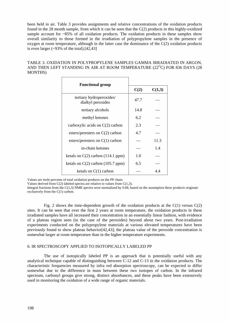
been held in air. Table 3 provides assignments and relative concentrations of the oxidation products found in the 28 month sample, from which it can be seen that the C(2) products in this highly-oxidized sample account for ~85% of all oxidation products. The oxidation products in these samples show overall similarity to those formed in the irradiation of polypropylene samples in the presence of oxygen at room temperature, although in the latter case the dominance of the C(2) oxidation products is even larger (~93% of the total).[42,43]
TABLE 3. OXIDATION IN POLYPROPYLENE SAMPLES GAMMA IRRADIATED IN ARGON, AND THEN LEFT STANDING IN AIR AT ROOM TEMPERATURE (22OC) FOR 836 DAYS (28 MONTHS)
Functional group C(2) C(1,3)
tertiary hydroperoxides/ dialkyl peroxides 47.7 —
tertiary alcohols 14.8 —
methyl ketones 6.2 —
carboxylic acids on C(2) carbon 2.3 —
esters/peresters on C(2) carbon 4.7 —
esters/peresters on C(1) carbon — 11.3
in-chain ketones — 1.4
ketals on C(2) carbon (114.1 ppm) 1.0 —
ketals on C(2) carbon (105.7 ppm) 6.5 —
ketals on C(1) carbon — 4.4 Values are mole percents of total oxidation products on the PP chain. Values derived from C(2) labeled spectra are relative to values from C(1,3). Integral fractions from the C(1,3) NMR spectra were normalized by 0.68, based on the assumption these products originate exclusively from the C(1) carbon.
Fig. 2 shows the time-dependent growth of the oxidation products at the C(1) versus C(2) sites. It can be seen that over the first 2 years at room temperature, the oxidation products in these irradiated samples have all increased their concentration in an essentially linear fashion, with evidence of a plateau region seen (in the case of the peroxides) beyond about two years. Post-irradiation experiments conducted on the polypropylene materials at various elevated temperatures have been previously found to show plateau behavior[42,43]; the plateau value of the peroxide concentration is somewhat larger at room temperature than in the higher temperature experiments.
6. IR SPECTROSCOPY APPLIED TO ISOTOPICALLY LABELED PP
The use of isotopically labeled PP is an approach that is potentially useful with any analytical technique capable of distinguishing between C-12 and C-13 in the oxidation products. The characteristic frequencies measured by infra red absorption spectroscopy, can be expected to differ somewhat due to the difference in mass between these two isotopes of carbon. In the infrared spectrum, carbonyl groups give strong, distinct absorbances, and these peaks have been extensively used in monitoring the oxidation of a wide range of organic materials.
198

0.00
2.00
4.00
6.00
8.00
10.00
0 200 400 600 800
Func
tiona
l gro
ups
per 1
00 m
ethi
ne (C
H) u
nits
Post-irradiation time (days)
(a)C(2)
0.00
2.00
4.00
6.00
8.00
10.00
0 200 400 600 800
Func
tiona
l gro
ups
per 1
00 la
bele
d C
H2
& C
H3 u
nits
Post-irradiation time (days)
(b)C(1,3)
FIG. 2. Accumulation of oxidation products in solid PP samples exposed to γ-radiation (240 kGy) in 24oC argon followed by post-irradiation thermal aging in 22oC air. (a) C(2) labeled sample; (b) C(1,3) labeled sample. Functional groups: (■) tertiary hydroperoxides and/or dialkyl peroxides; (♦) tertiary alcohols; (▲) methyl ketones; (Δ) in-chain ketones; (∇) carboxylic acids on C(2) carbon; (□) esters and/or peresters on C(2) carbon; (▼) esters and/or peresters on C(1) carbon; (◊) ketals on C(2) carbon (114.1 ppm); (○) ketals on C(2) carbon (105.7 ppm); (×) ketals on C(1) carbon (100–117 ppm). Dotted lines are guides to the eye.
To gain insight into the magnitude of absorption frequency shifts occurring in two of the major classes of polymer degradation products, carboxylic acids and ketones, we obtained samples of representative small organic molecules, octanoic acid and acetone, each with a single C-13 label at the carbonyl carbon atom. Fig. 3 shows the IR spectrum of these labeled compounds, superimposed on the spectrum of the corresponding, unlabeled material. It is seen that the peak corresponding to the carbon-oxygen double bond frequency is shifted by approximately 40 cm-1 to shorter wavelength in the C-13 labeled molecules.
Fig. 4 shows the carbonyl region for oxidized specimens of PP, including both labeled and unlabeled samples, which had been subjected to gamma irradiation to a dose of 270 kGy at 24oC. The carbonyl peaks in these materials represent a composite of oxidation products containing carbon-oxygen double bonds (acids, ketones, esters, etc.), and they are quite broad. However, the C(2) labeled PP shows a shift in the maximum intensity, compared with the C(1) and the unlabeled materials, of roughly 40 cm-1 to shorter wavelength. Since the majority of the oxidation products in the solid phase of the PP materials occur at the C(2) carbon, the IR results are consistent with expectation. Thus, in
199
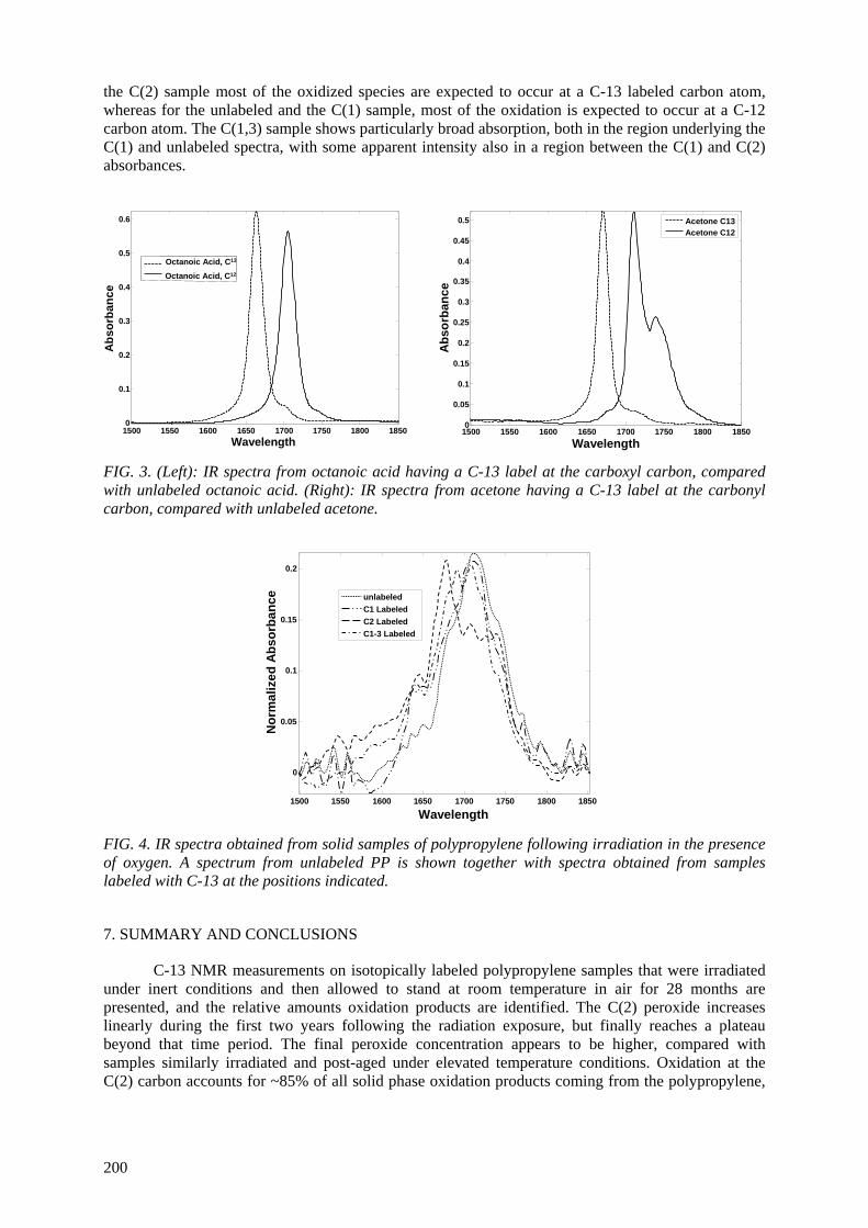
the C(2) sample most of the oxidized species are expected to occur at a C-13 labeled carbon atom, whereas for the unlabeled and the C(1) sample, most of the oxidation is expected to occur at a C-12 carbon atom. The C(1,3) sample shows particularly broad absorption, both in the region underlying the C(1) and unlabeled spectra, with some apparent intensity also in a region between the C(1) and C(2) absorbances.
1500 1550 1600 1650 1700 1750 1800 18500
0.1
0.2
0.3
0.4
0.5
0.6
Abs
orba
nce
Wavelength
Octanoic Acid, C13
Octanoic Acid, C12
1500 1550 1600 1650 1700 1750 1800 18500
0.05
0.1
0.15
0.2
0.25
0.3
0.35
0.4
0.45
0.5
Abs
orba
nce
Wavelength
Acetone C13Acetone C12
FIG. 3. (Left): IR spectra from octanoic acid having a C-13 label at the carboxyl carbon, compared with unlabeled octanoic acid. (Right): IR spectra from acetone having a C-13 label at the carbonyl carbon, compared with unlabeled acetone.
1500 1550 1600 1650 1700 1750 1800 1850
0
0.05
0.1
0.15
0.2
Nor
mal
ized
Abs
orba
nce
Wavelength
unlabeledC1 LabeledC2 LabeledC1-3 Labeled
FIG. 4. IR spectra obtained from solid samples of polypropylene following irradiation in the presence of oxygen. A spectrum from unlabeled PP is shown together with spectra obtained from samples labeled with C-13 at the positions indicated.
7. SUMMARY AND CONCLUSIONS
C-13 NMR measurements on isotopically labeled polypropylene samples that were irradiated under inert conditions and then allowed to stand at room temperature in air for 28 months are presented, and the relative amounts oxidation products are identified. The C(2) peroxide increases linearly during the first two years following the radiation exposure, but finally reaches a plateau beyond that time period. The final peroxide concentration appears to be higher, compared with samples similarly irradiated and post-aged under elevated temperature conditions. Oxidation at the C(2) carbon accounts for ~85% of all solid phase oxidation products coming from the polypropylene,
200
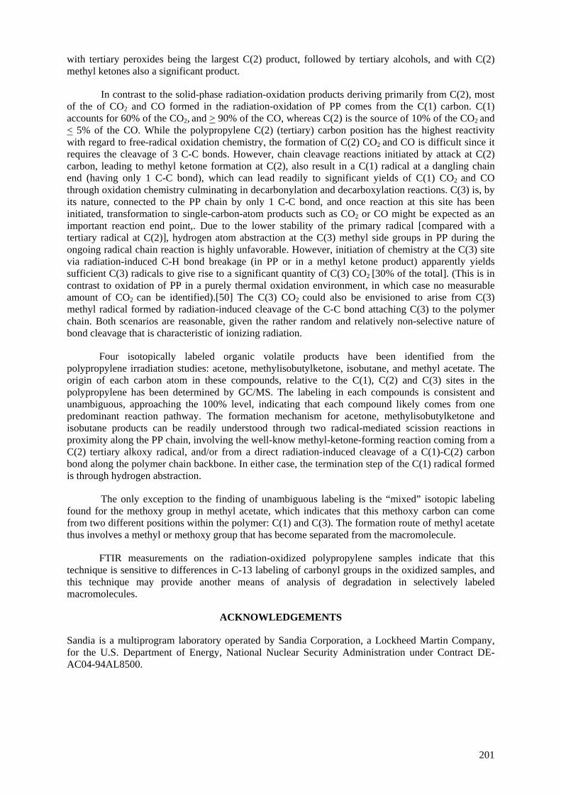
with tertiary peroxides being the largest C(2) product, followed by tertiary alcohols, and with C(2) methyl ketones also a significant product.
In contrast to the solid-phase radiation-oxidation products deriving primarily from C(2), most of the of CO2 and CO formed in the radiation-oxidation of PP comes from the C(1) carbon. C(1) accounts for 60% of the CO2, and > 90% of the CO, whereas C(2) is the source of 10% of the CO2 and < 5% of the CO. While the polypropylene C(2) (tertiary) carbon position has the highest reactivity with regard to free-radical oxidation chemistry, the formation of C(2) CO2 and CO is difficult since it requires the cleavage of 3 C-C bonds. However, chain cleavage reactions initiated by attack at C(2) carbon, leading to methyl ketone formation at C(2), also result in a C(1) radical at a dangling chain end (having only 1 C-C bond), which can lead readily to significant yields of C(1) CO2 and CO through oxidation chemistry culminating in decarbonylation and decarboxylation reactions. C(3) is, by its nature, connected to the PP chain by only 1 C-C bond, and once reaction at this site has been initiated, transformation to single-carbon-atom products such as CO2 or CO might be expected as an important reaction end point,. Due to the lower stability of the primary radical [compared with a tertiary radical at C(2)], hydrogen atom abstraction at the C(3) methyl side groups in PP during the ongoing radical chain reaction is highly unfavorable. However, initiation of chemistry at the C(3) site via radiation-induced C-H bond breakage (in PP or in a methyl ketone product) apparently yields sufficient C(3) radicals to give rise to a significant quantity of C(3) CO2 [30% of the total]. (This is in contrast to oxidation of PP in a purely thermal oxidation environment, in which case no measurable amount of CO2 can be identified).[50] The C(3) CO2 could also be envisioned to arise from C(3) methyl radical formed by radiation-induced cleavage of the C-C bond attaching C(3) to the polymer chain. Both scenarios are reasonable, given the rather random and relatively non-selective nature of bond cleavage that is characteristic of ionizing radiation.
Four isotopically labeled organic volatile products have been identified from the polypropylene irradiation studies: acetone, methylisobutylketone, isobutane, and methyl acetate. The origin of each carbon atom in these compounds, relative to the C(1), C(2) and C(3) sites in the polypropylene has been determined by GC/MS. The labeling in each compounds is consistent and unambiguous, approaching the 100% level, indicating that each compound likely comes from one predominant reaction pathway. The formation mechanism for acetone, methylisobutylketone and isobutane products can be readily understood through two radical-mediated scission reactions in proximity along the PP chain, involving the well-know methyl-ketone-forming reaction coming from a C(2) tertiary alkoxy radical, and/or from a direct radiation-induced cleavage of a C(1)-C(2) carbon bond along the polymer chain backbone. In either case, the termination step of the C(1) radical formed is through hydrogen abstraction.
The only exception to the finding of unambiguous labeling is the “mixed” isotopic labeling found for the methoxy group in methyl acetate, which indicates that this methoxy carbon can come from two different positions within the polymer: C(1) and C(3). The formation route of methyl acetate thus involves a methyl or methoxy group that has become separated from the macromolecule.
FTIR measurements on the radiation-oxidized polypropylene samples indicate that this technique is sensitive to differences in C-13 labeling of carbonyl groups in the oxidized samples, and this technique may provide another means of analysis of degradation in selectively labeled macromolecules.
ACKNOWLEDGEMENTS
Sandia is a multiprogram laboratory operated by Sandia Corporation, a Lockheed Martin Company, for the U.S. Department of Energy, National Nuclear Security Administration under Contract DE-AC04-94AL8500.
201
REFERENCES
[1] CLOUGH, R.L., SHALABY, S.W., Eds. Radiation effects on polymers; American Chemical Society: Washington, DC (1990).
[2] CLOUGH, R.L., GILLEN, K.T., DOLE, M., Radiation resistance of polymers and composites In Irradiation effects on polymers; CLEGG, D. W., COLLYER, A. A., Eds.; Elsevier: London (1991) 79-156.
[3] CLOUGH, R.L., "Review of the 5 IRaP conference", Nuclear Instruments and Methods in Physics Research B 208 (2003) 1-3.
[4] CLOUGH, R.L., "Enhancing polymers with radiation", Nuclear News April (2000) 32-37. [5] CLOUGH, R.L., Radiation resistant polymers In Encylopdeia of polymer science and
engineering; 2nd ed.; Wiley and Sons: New York 13 (1988) 667-706. [6] CLOUGH, R.L., GILLEN, K.T., "Polymer degradation under ionizing radiation: The role of
ozone", Journal of Polymer Science: Part A-1 27 (1989) 2313-2324. [7] CLOUGH, R.L., "γ-radiation-oxidation of polycyclic aromatic hydrocarbons: Involvement of
singlet oxygen", Journal of American Chemical Society 102 (1980) 5242-5245. [8] CLOUGH, R.L., "High-energy radiation and polymers: A review of commercial processes and
emerging applications", Nuclear Instruments and Methods in Physics Research B 185 (2001) 8-33.
[9] BURILLO, G., CLOUGH, R.L., CZVIKOVSZKY, T., GUVEN, O., LE-MOEL, A., LIU, W., SINGH, A., YANG, J., ZAHARESCU, T., "Polymer recycling: Potential application of radiation technology", Radiation Physics and Chemistry 64 (2002) 41-51.
[10] CLOUGH, R.L., GILLEN, K.T., "Stabilizer additives in ionizing radiation environments under oxidizing conditions", Polymer Degradation and Stability 30 (1990) 309-317.
[11] CLOUGH, R.L., GILLEN, K.T., "Radiation-thermal degradation of PE and PVC: Mechanism of synergism and dose rate effects", Radiation Physics and Chemistry 18 (1981) 661-669.
[12] DUNN, T.S., WILLIAMS, E.E., WILLIAMS, J.L., "The dependence of radical termination rates on percent crystallinity in gamma irradiated isotactic polypropylene", Radiation Physics and Chemistry 19 (1982) 287.
[13] CLOUGH, R.L., MALONE, G.M., GILLEN, K.T., WALLACE, J.S., SINCLAIR, M.B., "Discoloration and subsequent recovery of optical polymers exposed to ionizing radiation", Polymer Degradation and Stability 49 (1995) 305-313.
[14] CLOUGH, R.L., GILLEN, K.T., "Investigation of cable deterioration inside reactor containment", Nuclear Technology 59 (1982) 344-354.
[15] CELINA, M., GILLEN, K.T., MALONE, G.M., CLOUGH, R.L., NELSON, W.H., JR., "Polymer materials and component evaluation in acidic-radiation environments", Radiation Physics and Chemistry 62 (2001) 153-161.
[16] ASSINK, R.A., CELINA, M., DUNBAR, T.D., ALAM, T.M., CLOUGH, R.L., GILLEN, K. T., "Analysis of hydroperoxides in solid polyethylene by mas 13C NMR and EPR", Macromolecules 33 (2000) 4023-4029.
[17] ALAM, T.M., CELINA, M., ASSINK, R.A., CLOUGH, R.L., GILLEN, K.T., "17O NMR investigation of oxidative degradation in polymers under γ-irradiation", Radiation Physics and Chemistry 60 (2001) 121-127.
[18] CHIEN, J.C.W., BOSS, C.R., "Polymer reactions. V. Kinetics of autoxidation of polypropylene", Journal of Polymer Science: Part A-1 5 (1967) 3091-3101.
[19] CHIEN, J.C.W., BOSS, C.R., "Polymer reactions. VI. Inhibited autoxidation of polypropylene", Journal of Polymer Science: Part A-1 5 (1967) 1683-1697.
[20] CHIEN, J.C.W., VANDENBERG, E.J., JABLONER, H., "Polymer reactions. III. Structure of polypropylene hydroperoxide", Journal of Polymer Science: Part A-1 6 (1968) 381-392.
[21] CARLSSON, D.J., WILES, D.M., "The photodegradation of polypropylene films. II. Photolysis of ketonic oxidation products", Macromolecules 2 (1969) 587-597.
[22] CARLSSON, D.J., WILES, D.M., "The photodegradation of polypropylene films. Iii. Photolysis of polypropylene hydroperoxides", Macromolecules 2 (1969) 597-606.
[23] ADAMS, J.H., "Analysis of the nonvolatile oxidation products of polypropylene Ii. Thermal oxidation", Journal of Polymer Science: Part A-1 8 (1970) 1077-1090.
[24] ADAMS, J.H., "Analysis of the nonvolatile oxidation products of polypropylene II. Process degradation", Journal of Polymer Science: Part A-1 8 (1970) 1269-1277.
[25] ADAMS, J.H., "Analysis of the nonvolatile oxidation products of polypropylene III. Photodegradation", Journal of Polymer Science: Part A-1 8 (1970) 1279-1288.
202
[26] NIKI, E., DECKER, C., MAYO, F.R., "Aging and degradation of polyolefins. I. Peroxide-initiated oxidations of atactic polypropylene", Journal of Polymer Science: Polymer Chemistry Edition 11 (1973) 2813-2845.
[27] DECKER, C., MAYO, F.R., "Aging and degradation of polyolefins. IIi. γ-initiated oxidations of atactic polypropylene", Journal of Polymer Science: Polymer Chemistry Edition 11 (1973) 2847-2877.
[28] CARLSSON, D.J., WILES, D.M., "The photooxidative degradation of polypropylene. Part 1. Photooxidation and photoinitiation processes", Journal of Macromolecular Science -- Reviews in Macromolecular Chemistry C14 (1976) 65-106.
[29] GEUSKENS, G., KABAMBA, M.S., "Photo-oxidation of polymers -- part V: A new chain scission mechanism in polyolefins", Polymer Degradation and Stability 4 (1982) 69-76.
[30] IRING, M., TÜDÖS, F., "Thermal oxidation of polyethylene and polypropylene: Effects of chemical structure and reaction conditions on the oxidation process", Progress in Polymer Science 15 (1990) 217-262.
[31] LACOSTE, J., VAILLANT, D., CARLSSON, D. J., "Gamma-, photo-, and thermally-initiated oxidation of isotactic polypropylene", Journal of Polymer Science: Part A: Polymer Chemistry 31 (1993) 715-722.
[32] GIJSMAN, P., HENNEKENS, J., VINCENT, J., "The mechanism of the low-temperature oxidation of polypropylene", Polymer Degradation and Stability 42 (1993) 95-105.
[33] CELINA, M., GEORGE, G.A., BILLINGHAM, N.C., "Physical spreading of oxidation in solid polypropylene as studied by chemiluminescence", Polymer Degradation and Stability 42 (1993) 335-344.
[34] GIJSMAN, P., KROON, M., OORSCHOT, M.V., "The role of peroxides in the thermooxidative degradation of polypropylene", Polymer Degradation and Stability 51 (1996) 3-13.
[35] GUGUMUS, F., "Thermooxidative degradation of polyolefins in the solid state -- 6. Kinetics of thermal oxidation of polypropylene", Polymer Degradation and Stability 62 (1998) 235-243.
[36] GEORGE, G.A., CELINA, M., Homogeneous and heterogeneous oxidation of polypropylene In Handbook of polymer degradation; Second Edition ed.; HAMID, S. H., Ed.; Marcel Dekker, Inc.: New York, 2000; pp 277-313.
[37] BARABÁS, K., IRING, M., LAZLO-HEDVIG, S., KELLEN, T., TUDOS, F., "Study of the thermal oxidation of polyolefines. VIII. Volatile products of polypropylene thermal oxidation", European Polymer Journal 14 (1978) 405-407.
[38] HOFF, A., JACOBSSON, S., "Thermal oxidation of polypropylene close to industrial processing conditions", Journal of Applied Polymer Science 27 (1982) 2539-2551.
[39] HOFF, A., JACOBSSON, S., "Thermal oxidation of polypropylene in the temperature range of 120-280 c", Journal of Applied Polymer Science 29 (1984) 465-480.
[40] PHILIPPART, J.L., POSADA, F., GARDETTE, J.L., "Mass spectroscopy analysis of volatile photoproducts in photooxidation of polypropylene", Polymer Degradation and Stability 49 (1995) 285-290.
[41] COMMEREUC, S., VAILLANT, D., PHILIPPART, J.L., LACOSTE, J., LEMAIRE, J., CARLSSON, D.J., "Photo and thermal decomposition of iPP hydroperoxides", Polymer Degradation and Stability 57 (1997) 175-182.
[42] MOWERY, D.M., ASSINK, R.A., DERZON, D.K., KLAMO, S.B., BERNSTEIN, R., CLOUGH, R.L., "Radiation oxidation of polypropylene: A solid-state 13C NMR study using selective isotopic labeling", Radiation Physics and Chemistry (in press).
[43] MOWERY, D.M., ASSINK, R.A., DERZON, D.K., KLAMO, S.B., CLOUGH, R.L., BERNSTEIN, R., "Solid-state 13C NMR investigation of the oxidative degradation of selectively labeled polypropylene by thermal aging and gamma-irradiation", Macromolecules 38 (2005) 5035-5046.
[44] BENNETT, A.E., RIENSTRA, C.M., AUGER, M., LAKSHMI, K.V., GRIFFIN, R.G., "Heteronuclear decoupling in rotating solids", Journal of Chemical Physics 103 (1995) 6951-6958.
[45] MARSHAL, A.G., HENDRICKSON, C.L., JACKSON, G.S., "Fourier transform ion cyclotron resonance mass spectrometry: A primer", Mass Spectrometry Reviews 17 (1998) 1-35.
[46] BRESLOW, R., Organic reaction mechanisms an introduction; W. A. Benjamin: Menlo Park, 1969.
[47] PRYOR, W.A., Free radicals; McGraw-Hill: New York, 1966. [48] WALLING, C., Free radicals in solution; John Wiley & Sons: New York, 1957.
203
[49] CLOUGH, R.L., "Isotopic exchange in gamma-irradiated mixtures of C24H50 and C24D50: Evidence of free radical migration in the solid state", Journal of Chemical Physics 87 (1987) 1588-1595.
[50] THORNBERG, S.M., BERNSTEIN, R., DERZON, D.K., IRWIN, A.N., KLAMO, S.B., CLOUGH, R.L., "The genesis of CO2 and CO in the thermooxidative degradation of polypropylene", Polymer Degradation and Stability (Polymer Degradation and Stability, in press).
204
APPLICATION OF CHITIN/CHITOSAN IN AGRICULTURE TRUONG THI HANH, NGUYEN QUOC HIEN, TRAN TICH CANH Research and Development Centre for Radiation Technology Vietnam Atomic Energy Commission, Vietnam
Abstract Chitosan is the deacetylated derivative of chitin and deacetylation degree is an important chemical characteristic which could be determined by HNMR or IR. spectroscopy. Chitosan of high deacetylation degree (87.37%) was oxidized by hydrogen peroxide at 0.6M concentration for 4 hours to obtain low molecular weight ~ 6.0 × 10⁴, further degradation was carried out by irradiation of chitosan in solution (4%, w/v) with gamma Co-60 rays, in the dose range from 10 kGy to 70 kGy. The test in the field for antifungus of Rhizoctonia Solani on rice plants was investigated. The antifungal effect of resultant chitosan at dose of 50 kGy and concentration of 80 ppm was most effective. 1. INTRODUCTION
Chitosan, poly-β-(1→4)-D glucosamine, is the deacetylated derivative of chitin and the degree of deacetylation (DD) of this product is an important chemical characteristic which could be determined by IR and HNMR spectroscopy [1]. Chitin and chitosan have been used in variety of applications such as in food processing, water treament, cosmetic, medicine, agriculture. [2]. However, in some fields, the application of this polysaccharide is limited by its high molecular weight (MW) so that the degradation of chitosan to prepare low MW chitosan or oligochitosan has been considered.
At present, three methods for degradation of chitosan including chemical treament, enzymatic
hydrolysis and radiation technology can be applied. Enzymatic hydrolysis leads to the production of low MW chitosan with high yield but the enzymes are too expensive to be commercialized. Besides, several oxidative reagents have been studied for degradation of chitosan to obtain low MW but further degradation by chemical influenced on structure of glucosamine ring [3]. In this study, degradation of chitosan was carried out by combination of oxidation reagent and irradiation with Co-60. Resultant products were tested in the field for prevention of infection by Rhizoctonia Solani that is one of the serious pathogenesis fungi for rice plants in the tropics.
Several authors also proved the antifungal effect of degraded chitosan. Results showed that
chitosan having degree of polymerization (DP) from 2 to 8 has been recognized as phytoalexin inducer to prevent infection of Pyricularia Oryzae in suspension cultured rice cells [4]. D. Roby et al. demontrated oligomers from hexamer to nonamer of oligochitosan induced elicitor activity for infection inhibition by Colletotrichum Lagenarium in melon plant [5]. Thus, oligochitosan is very promising to utilize in agriculture for enhancement of immune system against infection of diseases in plants.
2. MATERIALS AND METHODS 2.1. Materials
Chitosan used in this work was made from shrimp shell which was supplied by the seafood export company. All chemicals and solvents were used as analytical reagent grade.
205
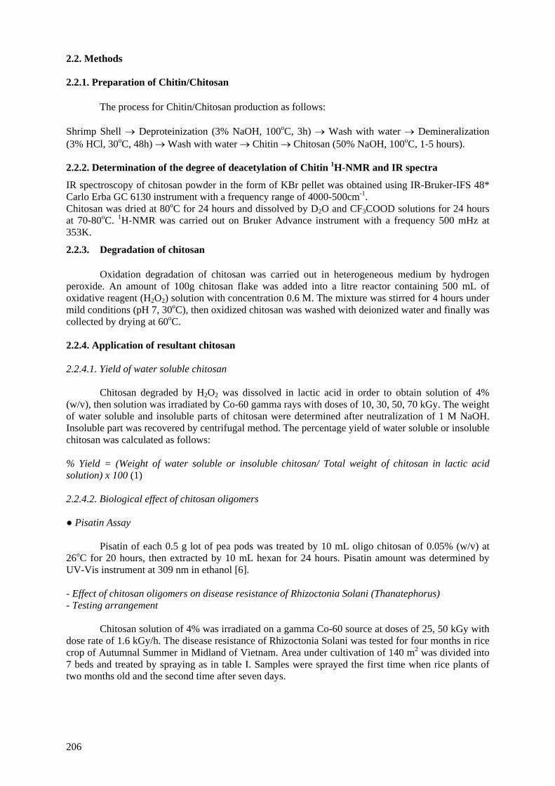
2.2. Methods 2.2.1. Preparation of Chitin/Chitosan
The process for Chitin/Chitosan production as follows:
Shrimp Shell → Deproteinization (3% NaOH, 100oC, 3h) → Wash with water → Demineralization (3% HCl, 30oC, 48h) → Wash with water → Chitin → Chitosan (50% NaOH, 100oC, 1-5 hours). 2.2.2. Determination of the degree of deacetylation of Chitin 1H-NMR and IR spectra
IR spectroscopy of chitosan powder in the form of KBr pellet was obtained using IR-Bruker-IFS 48* Carlo Erba GC 6130 instrument with a frequency range of 4000-500cm-1. Chitosan was dried at 80oC for 24 hours and dissolved by D2O and CF3COOD solutions for 24 hours at 70-80oC. 1H-NMR was carried out on Bruker Advance instrument with a frequency 500 mHz at 353K.
2.2.3. Degradation of chitosan
Oxidation degradation of chitosan was carried out in heterogeneous medium by hydrogen peroxide. An amount of 100g chitosan flake was added into a litre reactor containing 500 mL of oxidative reagent (H2O2) solution with concentration 0.6 M. The mixture was stirred for 4 hours under mild conditions (pH 7, 30oC), then oxidized chitosan was washed with deionized water and finally was collected by drying at 60oC.
2.2.4. Application of resultant chitosan 2.2.4.1. Yield of water soluble chitosan
Chitosan degraded by H2O2 was dissolved in lactic acid in order to obtain solution of 4% (w/v), then solution was irradiated by Co-60 gamma rays with doses of 10, 30, 50, 70 kGy. The weight of water soluble and insoluble parts of chitosan were determined after neutralization of 1 M NaOH. Insoluble part was recovered by centrifugal method. The percentage yield of water soluble or insoluble chitosan was calculated as follows:
% Yield = (Weight of water soluble or insoluble chitosan/ Total weight of chitosan in lactic acid solution) x 100 (1) 2.2.4.2. Biological effect of chitosan oligomers ● Pisatin Assay
Pisatin of each 0.5 g lot of pea pods was treated by 10 mL oligo chitosan of 0.05% (w/v) at 26oC for 20 hours, then extracted by 10 mL hexan for 24 hours. Pisatin amount was determined by UV-Vis instrument at 309 nm in ethanol [6].
- Effect of chitosan oligomers on disease resistance of Rhizoctonia Solani (Thanatephorus) - Testing arrangement
Chitosan solution of 4% was irradiated on a gamma Co-60 source at doses of 25, 50 kGy with dose rate of 1.6 kGy/h. The disease resistance of Rhizoctonia Solani was tested for four months in rice crop of Autumnal Summer in Midland of Vietnam. Area under cultivation of 140 m2 was divided into 7 beds and treated by spraying as in table I. Samples were sprayed the first time when rice plants of two months old and the second time after seven days.
206
TABLE 1. TESTED FORMULA
Sample Concentration
0 kGy 40 ppm 25 kGy 40 ppm 50 kGy 40 ppm 50 kGy 80 ppm 50 kGy 20 ppm
Validacin 3DD 1.5 litre/ha Control Water
- Testing method
50 plants of rice on two diagonal of bed with disease plants were divided into various degrees namely “Four levels” in Regulation of testing in the field which Ministery of Agriculture and Rural Development Vietnam promulgated. Disease ratio and disease index were calculated as follows:
Disease ratio (%) = m/N x 100 (2)
Where m and N were disease plants and total plants investigated.
Disease index (%) = [(4n1 +3n2 + 2n3 +n4)/ 4N] x 100 (3)
Where n1 were plants with the disease inear ocrea, n2, n3, n4 were plants which had the first, second, third ocrea respectively under inear ocrea infected. 3. RESULTS AND DISCUSSION 3.1. The deacetylation degree of Chitin/Chitosan by 1H-NMR and IR spectra:
1HNRM spectroscopy is one of the most useful methods for studying the structure of carbohydrates. Degree of deacetylation of chitin was determined from the interaction of protons in D-glucosamine and N-acetyl D-glucosamine of chitosan. 1HNMR spectroscopy of deacetylation chitosan for 3 hours is shown in Fig.1. The signals at the chemical shifts of δ= 5.2 ppm and δ= 2.4 ppm assigned to proton of H1 when interaction with H2 and proton of –COCH3 group respectively. The degree of acetylation was calculated from integral intensities of protons in –COCH3 group (I COCH3= 0.446) and proton of H1 (IH1=1) about 15%, the result of deacetylation degree to be 85%.
In the IR spectroscopic method, some authors estimated DD based on the absorbance intensity of the hydroxyl group at frequency 3400cm-1 and the amide I band at 1650cm-1. However, from structural units investigation and especially an absorbance peak at 3400 cm-1 has inaccurate intensity because of water adsorption. Another equation was proposed by Brugnerotto [1]:
A1320/A1420 = 0.3822 + 0.03133 x DA (4)
Where A1320 and A1420 were the absorbance of C-N and C-H (CH3) bending respectively, DA was the degree of acetylation.
Table 3 showed the values of deacetylation degree of chitosan for deacetylation time of 1,2 3,5 hours. The DD of sample for 3 hours obtained to be 87.37%, it was good agreement with result based on 1HNMR. When the deacetylation time was longer than 3 hours, DA increased insignificantly so that chitosan sample deacetylated for 3 hours was chosen for further study.
207

N H C O C H 3H
O H
C H 2 O HO
O O
n
C h it in
N H 2H
O H
C H 2 O HO
O O
n
C h ito s a n
1
23
45
6
1 '2 '3 '
4 '5 '
6 '
FIG.1. HNMR spectrum of deacetylated chitosan for 3 hours. Infrared spectral absorbance of chitosan is shown in Fig.2. Major peaks are presented in table 2.
FIG. 2. IR spectrum of deacetylated chitosan for 3 hours.
TABLE 2. CHARACTERISTIC FUNCTIONAL GROUPS OF CHITOSAN FROM IR SPECTRA
Frequency (cm-1) Functional groups 3400 O-H stretch 2880 C-H stretch 1650 C=O stretch and N-H bend 1420 C-H bend (CH3) 1320 C-N bend
208
TABLE 3. DEACETYLATION DEGREE FROM IR SPECTRA
Deacetylation Time, h Temperature, oC
NaOH Concentration, % (w/v)
A1320 A1420 DA (%)
DD (%)
1h, 100oC, NaOH 50% 1.00 1.05 18.19 81.81 2h, 100oC, NaOH 50% 1.00 1.10 16.81 83.19 3h, 100oC, NaOH 50% 0.70 0.90 12.63 87.37 5h, 100oC, NaOH 50% 0.80 1.05 12.12 87.88 48h, 30oC, NaOH 30% 0.944 0.307 85.79 14.21 48h, 30oC, NaOH 35% 0.055 0.118 56.28 43.72 48h, 30oC, NaOH 40% 0.198 0.141 32.63 67.37
3.2. Degradation of chitosan by oxidative reagents combined with radiation
Degradation of chitosan by H2O2 combined with radiation can be estimated by calculating the radiation degradation yields (Gd) [7]. As shown in Table 4, Gd values of chitosan and oxidized chitosan by 0.6 M H2O2 and 1.2 M H2O2 for 4 hours are 1.04, 5.10 and 11.24 respectively when chitosan were irradiated in the dose range of 5 to 30 kGy. Hence, it is concluded that the oxidative chitosan was found to be more susceptible to radiation than the non-oxidative one. This is a method to reduce absorbed dose for degradation of chitosan. Kume et al. reported that to induce pisatin in soybean, chitosan was irradiated to 1000 kGy [8], in this case, if oxidized chitosan is used, radiation dose will be much decreased.
TABLE 4. GD VALUE OF IRRADIATED CHITOSAN
Sample Gd Control 1.04
0.6M H2O2 5.10 1.2M H2O2 11.24
3.3. Biological effect of chitosan oligomers 3.3.1. Pisatin assay
Effect of pisatin inducement of chitosan fragments and glucosamine was investigated by Hadwiger and Beckman [6]. Chitosan implicated in the pea pod – Fusarium Solani interaction as an elicitor of phytoalexin production, inhibition of fungal growth and a substance which can protect pea tissue.
Phytoalexin, pisatin was also induced by irradiated chitosan. In the Fig.1, the chitosan fragments obtained by irradiated chitosan solution (4%) to dose of 30 kGy induced pisatin which increased twofold in comparison with unirradiated chitosan, molecular weight about 6 × 10⁴ that was treated by oxidation agent first. In this experiment, stimulation for synthesis of phytoalexin in the pea pod was very high when chitosans were irradiated at the doses of 50, 70 kGy. It is explained that degraded chitosan by radiation changed the size of chitosan fragments so enhanced penetration of oligochitosan into cell wall of pea pod tissue.
209
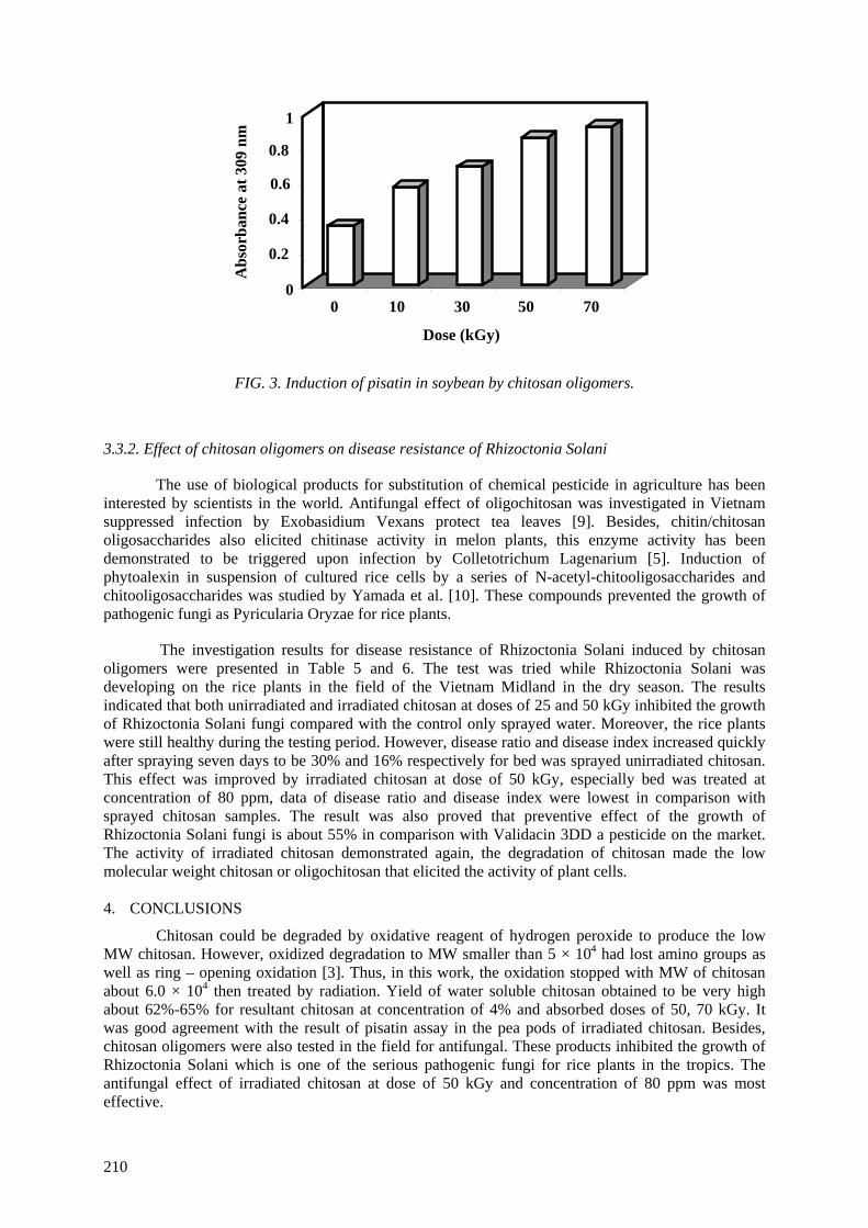
0
0.2
0.4
0.6
0.8
1
Abs
orba
nce
at 3
09 n
m
0 10 30 50 70
Dose (kGy)
FIG. 3. Induction of pisatin in soybean by chitosan oligomers.
3.3.2. Effect of chitosan oligomers on disease resistance of Rhizoctonia Solani
The use of biological products for substitution of chemical pesticide in agriculture has been interested by scientists in the world. Antifungal effect of oligochitosan was investigated in Vietnam suppressed infection by Exobasidium Vexans protect tea leaves [9]. Besides, chitin/chitosan oligosaccharides also elicited chitinase activity in melon plants, this enzyme activity has been demonstrated to be triggered upon infection by Colletotrichum Lagenarium [5]. Induction of phytoalexin in suspension of cultured rice cells by a series of N-acetyl-chitooligosaccharides and chitooligosaccharides was studied by Yamada et al. [10]. These compounds prevented the growth of pathogenic fungi as Pyricularia Oryzae for rice plants.
The investigation results for disease resistance of Rhizoctonia Solani induced by chitosan oligomers were presented in Table 5 and 6. The test was tried while Rhizoctonia Solani was developing on the rice plants in the field of the Vietnam Midland in the dry season. The results indicated that both unirradiated and irradiated chitosan at doses of 25 and 50 kGy inhibited the growth of Rhizoctonia Solani fungi compared with the control only sprayed water. Moreover, the rice plants were still healthy during the testing period. However, disease ratio and disease index increased quickly after spraying seven days to be 30% and 16% respectively for bed was sprayed unirradiated chitosan. This effect was improved by irradiated chitosan at dose of 50 kGy, especially bed was treated at concentration of 80 ppm, data of disease ratio and disease index were lowest in comparison with sprayed chitosan samples. The result was also proved that preventive effect of the growth of Rhizoctonia Solani fungi is about 55% in comparison with Validacin 3DD a pesticide on the market. The activity of irradiated chitosan demonstrated again, the degradation of chitosan made the low molecular weight chitosan or oligochitosan that elicited the activity of plant cells.
4. CONCLUSIONS
Chitosan could be degraded by oxidative reagent of hydrogen peroxide to produce the low MW chitosan. However, oxidized degradation to MW smaller than 5 × 10⁴ had lost amino groups as well as ring – opening oxidation [3]. Thus, in this work, the oxidation stopped with MW of chitosan about 6.0 × 10⁴ then treated by radiation. Yield of water soluble chitosan obtained to be very high about 62%-65% for resultant chitosan at concentration of 4% and absorbed doses of 50, 70 kGy. It was good agreement with the result of pisatin assay in the pea pods of irradiated chitosan. Besides, chitosan oligomers were also tested in the field for antifungal. These products inhibited the growth of Rhizoctonia Solani which is one of the serious pathogenic fungi for rice plants in the tropics. The antifungal effect of irradiated chitosan at dose of 50 kGy and concentration of 80 ppm was most effective.
210
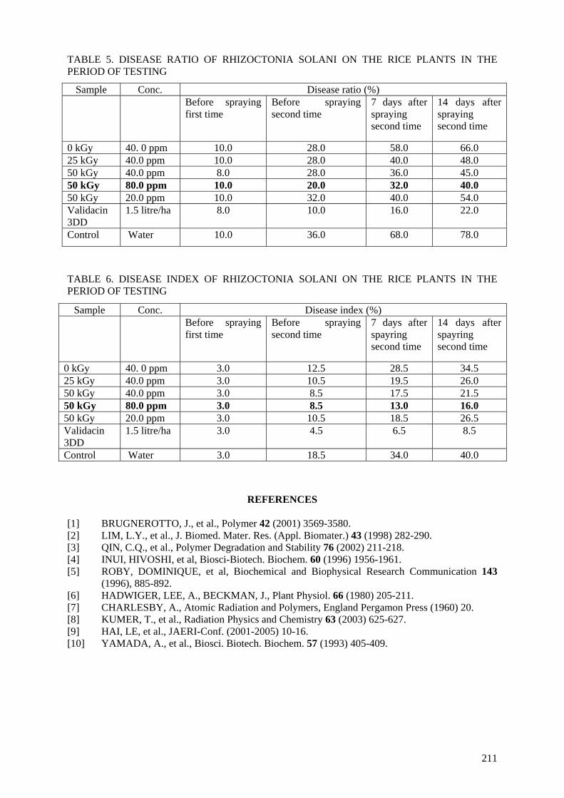
TABLE 5. DISEASE RATIO OF RHIZOCTONIA SOLANI ON THE RICE PLANTS IN THE PERIOD OF TESTING
Sample Conc. Disease ratio (%) Before spraying
first time Before spraying second time
7 days after spraying second time
14 days after spraying second time
0 kGy 40. 0 ppm 10.0 28.0 58.0 66.0 25 kGy 40.0 ppm 10.0 28.0 40.0 48.0 50 kGy 40.0 ppm 8.0 28.0 36.0 45.0 50 kGy 80.0 ppm 10.0 20.0 32.0 40.0 50 kGy 20.0 ppm 10.0 32.0 40.0 54.0 Validacin 3DD
1.5 litre/ha 8.0 10.0 16.0 22.0
Control Water 10.0 36.0 68.0 78.0
TABLE 6. DISEASE INDEX OF RHIZOCTONIA SOLANI ON THE RICE PLANTS IN THE PERIOD OF TESTING
Sample Conc. Disease index (%) Before spraying
first time Before spraying second time
7 days after spayring second time
14 days after spayring second time
0 kGy 40. 0 ppm 3.0 12.5 28.5 34.5 25 kGy 40.0 ppm 3.0 10.5 19.5 26.0 50 kGy 40.0 ppm 3.0 8.5 17.5 21.5 50 kGy 80.0 ppm 3.0 8.5 13.0 16.0 50 kGy 20.0 ppm 3.0 10.5 18.5 26.5 Validacin 3DD
1.5 litre/ha 3.0 4.5 6.5 8.5
Control Water 3.0 18.5 34.0 40.0
REFERENCES
[1] BRUGNEROTTO, J., et al., Polymer 42 (2001) 3569-3580. [2] LIM, L.Y., et al., J. Biomed. Mater. Res. (Appl. Biomater.) 43 (1998) 282-290. [3] QIN, C.Q., et al., Polymer Degradation and Stability 76 (2002) 211-218. [4] INUI, HIVOSHI, et al, Biosci-Biotech. Biochem. 60 (1996) 1956-1961. [5] ROBY, DOMINIQUE, et al, Biochemical and Biophysical Research Communication 143
(1996), 885-892. [6] HADWIGER, LEE, A., BECKMAN, J., Plant Physiol. 66 (1980) 205-211. [7] CHARLESBY, A., Atomic Radiation and Polymers, England Pergamon Press (1960) 20. [8] KUMER, T., et al., Radiation Physics and Chemistry 63 (2003) 625-627. [9] HAI, LE, et al., JAERI-Conf. (2001-2005) 10-16. [10] YAMADA, A., et al., Biosci. Biotech. Biochem. 57 (1993) 405-409.
211


APPLICATION OF CHITIN/CHITOSAN IN ENVIRONMENT TRUONG THI HANH, NGUYEN QUOC HIEN, TRAN TICH CANH Research and Development Centre for Radiation Technology, Vietnam Atomic Energy Commission, Vietnam
Abstract Partially deacetylated chitin (PD-chitin) was modified grafting with acrylic acid (AAc) by direct radiation grafting. The dependence of the grafting rate on the monomer concentration was determined to be Vg = k[M]1.11. Mohr’s salt was used as homopolymer formation inhibitor with the suitable concentration of 1% (w/v). The adsorption of dyes (Direct Yellow, Acid Blue and Direct Blue) and metal ions (Zn2+, Cr6+, Cu2+) onto grafted chitin were studied. The highest uptake capacities were found to be 303 mg/g and 1.157 × 10⁻² moles/g for Direct Yellow and Zn2+ respectively. 1. INTRODUCTION
Natural polymers such as alginate, chitin/chitosan, starch, cellulose have been studied and
applied in the many fields such as in food processing, water treatment, cosmetic, medicine, agriculture. [1] The radiation technology has been applied to modify polymers for multi purposes including environmental treatment.
At present, some papers of polymer modification for adsorption of toxic heavy metal ions as
well as dyes were reported [2,3,4,5]. Radiation technology was also applied for grafting of monomers on polymers matrix making adsorbent. Several authors used chitosan of low deacetylation degree as adsorption material of dyes and metal ions [2]. Grafting modification of poly(vinyl acetate), acrylic acid on chitosan by radiation technology enhanced adsorption of metal ions on chitosan [3]. Modification of cotton – cellulose by preirradiation grafting with acrylamide, acrylic acid… for iodine adsorption [4]. Grafting acrylonitril and methacrylic acid onto polyethylene by radiation to prepare adsorbent for the recovery of uranium from seawater was carried out [5].
In our country, modification of polymer by radiation for environmental treatment has been
considered. This study focuses on radiation grafting processing from abundant material as chitin/chitosan with acrylic acid for making adsorbent of dyes and metal ions.
2. MATERIALS AND METHODS 2.1. Materials
Chitin used in this work was made from shrimp shell which was supplied by the seafood export company. Acrylic acid and other chemicals were used as analytical reagent grade.
2.2. Methods
2.2.1. Deacetylation of chitin
At first, shrimp shell was eliminated protein and mineral then partially deacetylated by NaOH solution with concentration in the range from 30 to 40% at 30oC for two days. The degree of deacetylation of partially deacetylated chitin (PD-chitin) was determined by IR spectroscopy [6].
213
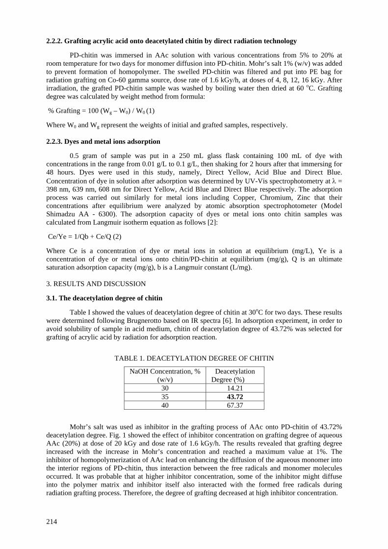
2.2.2. Grafting acrylic acid onto deacetylated chitin by direct radiation technology
PD-chitin was immersed in AAc solution with various concentrations from 5% to 20% at room temperature for two days for monomer diffusion into PD-chitin. Mohr’s salt 1% (w/v) was added to prevent formation of homopolymer. The swelled PD-chitin was filtered and put into PE bag for radiation grafting on Co-60 gamma source, dose rate of 1.6 kGy/h, at doses of 4, 8, 12, 16 kGy. After irradiation, the grafted PD-chitin sample was washed by boiling water then dried at 60 oC. Grafting degree was calculated by weight method from formula:
% Grafting = 100 (Wg – W0) / W0 (1) Where W0 and Wg represent the weights of initial and grafted samples, respectively. 2.2.3. Dyes and metal ions adsorption
0.5 gram of sample was put in a 250 mL glass flask containing 100 mL of dye with concentrations in the range from 0.01 g/L to 0.1 g/L, then shaking for 2 hours after that immersing for 48 hours. Dyes were used in this study, namely, Direct Yellow, Acid Blue and Direct Blue. Concentration of dye in solution after adsorption was determined by UV-Vis spectrophotometry at λ = 398 nm, 639 nm, 608 nm for Direct Yellow, Acid Blue and Direct Blue respectively. The adsorption process was carried out similarly for metal ions including Copper, Chromium, Zinc that their concentrations after equilibrium were analyzed by atomic absorption spectrophotometer (Model Shimadzu AA - 6300). The adsorption capacity of dyes or metal ions onto chitin samples was calculated from Langmuir isotherm equation as follows [2]:
Ce/Ye = 1/Qb + Ce/Q (2) Where Ce is a concentration of dye or metal ions in solution at equilibrium (mg/L), Ye is a concentration of dye or metal ions onto chitin/PD-chitin at equilibrium (mg/g), Q is an ultimate saturation adsorption capacity (mg/g), b is a Langmuir constant (L/mg). 3. RESULTS AND DISCUSSION 3.1. The deacetylation degree of chitin
Table I showed the values of deacetylation degree of chitin at 30oC for two days. These results were determined following Brugnerotto based on IR spectra [6]. In adsorption experiment, in order to avoid solubility of sample in acid medium, chitin of deacetylation degree of 43.72% was selected for grafting of acrylic acid by radiation for adsorption reaction.
TABLE 1. DEACETYLATION DEGREE OF CHITIN
NaOH Concentration, % (w/v)
Deacetylation Degree (%)
30 14.21 35 43.72 40 67.37
Mohr’s salt was used as inhibitor in the grafting process of AAc onto PD-chitin of 43.72%
deacetylation degree. Fig. 1 showed the effect of inhibitor concentration on grafting degree of aqueous AAc (20%) at dose of 20 kGy and dose rate of 1.6 kGy/h. The results revealed that grafting degree increased with the increase in Mohr’s concentration and reached a maximum value at 1%. The inhibitor of homopolymerization of AAc lead on enhancing the diffusion of the aqueous monomer into the interior regions of PD-chitin, thus interaction between the free radicals and monomer molecules occurred. It was probable that at higher inhibitor concentration, some of the inhibitor might diffuse into the polymer matrix and inhibitor itself also interacted with the formed free radicals during radiation grafting process. Therefore, the degree of grafting decreased at high inhibitor concentration.
214
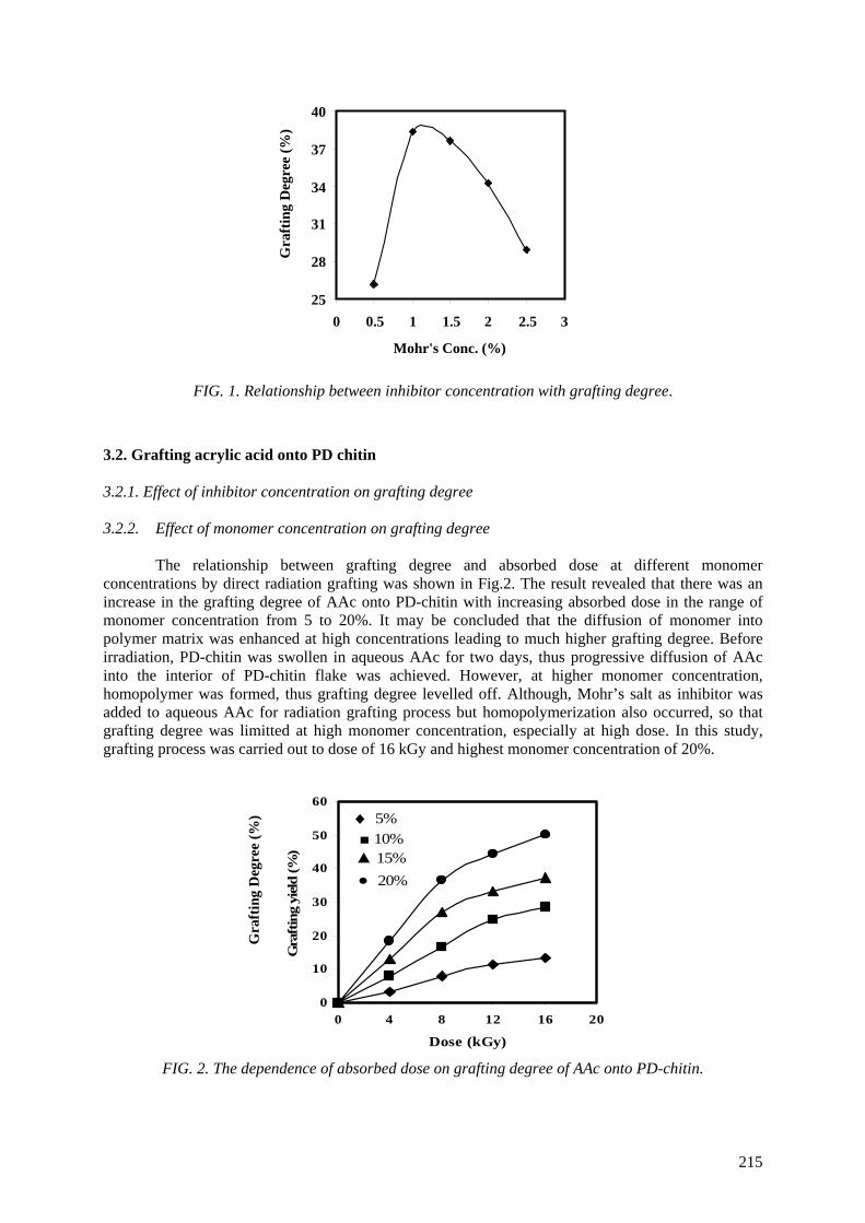
25
28
31
34
37
40
0 0.5 1 1.5 2 2.5 3
Mohr's Conc. (%)
Gra
ftin
g D
egre
e (%
)
FIG. 1. Relationship between inhibitor concentration with grafting degree.
3.2. Grafting acrylic acid onto PD chitin 3.2.1. Effect of inhibitor concentration on grafting degree
3.2.2. Effect of monomer concentration on grafting degree
The relationship between grafting degree and absorbed dose at different monomer concentrations by direct radiation grafting was shown in Fig.2. The result revealed that there was an increase in the grafting degree of AAc onto PD-chitin with increasing absorbed dose in the range of monomer concentration from 5 to 20%. It may be concluded that the diffusion of monomer into polymer matrix was enhanced at high concentrations leading to much higher grafting degree. Before irradiation, PD-chitin was swollen in aqueous AAc for two days, thus progressive diffusion of AAc into the interior of PD-chitin flake was achieved. However, at higher monomer concentration, homopolymer was formed, thus grafting degree levelled off. Although, Mohr’s salt as inhibitor was added to aqueous AAc for radiation grafting process but homopolymerization also occurred, so that grafting degree was limitted at high monomer concentration, especially at high dose. In this study, grafting process was carried out to dose of 16 kGy and highest monomer concentration of 20%.
0
10
20
30
40
50
60
0 4 8 12 16
Dose (kGy)
Gra
ftin
g yi
eld
(%)
♦ 5% ■ 10%▲ 15% • 20%
Gra
ftin
g D
egre
e (%
)
20
FIG. 2. The dependence of absorbed dose on grafting degree of AAc onto PD-chitin.
215
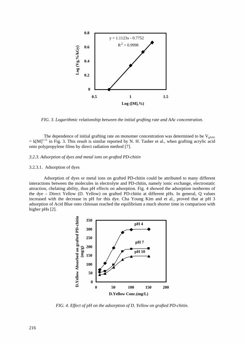
y = 1.1123x - 0.7752
R2 = 0.9998
0
0.2
0.4
0.6
0.8
0.5 1 1.5
Log ([M],%)
Log
(Vg,
%/k
Gy)
FIG. 3. Logarithmic relationship between the initial grafting rate and AAc concentration.
The dependence of initial grafting rate on monomer concentration was determined to be VgAAc
= k[M]1.11 in Fig. 3. This result is similar reported by N. H. Tasher et al., when grafting acrylic acid onto polypropylene films by direct radiation method [7]. 3.2.3. Adsorption of dyes and metal ions on grafted PD-chitin 3.2.3.1. Adsorption of dyes
Adsorption of dyes or metal ions on grafted PD-chitin could be attributed to many different interactions between the molecules in electrolyte and PD-chitin, namely ionic exchange, electrostatic attraction, chelating ability, thus pH effects on adsorption. Fig. 4 showed the adsorption isotherms of the dye – Direct Yellow (D. Yellow) on grafted PD-chitin at different pHs. In general, Q values increased with the decrease in pH for this dye. Cha Young Kim and et al., proved that at pH 3 adsorption of Acid Blue onto chitosan reached the equilibrium a much shorter time in comparison with higher pHs [2].
0
50
100
150
200
250
300
350
0 50 100 150 200D.Yellow Conc.(mg/L)
pH 4
pH 7
pH 10
D.Y
ello
w A
bsor
bed
on g
raft
ed P
D-c
hitin
(m
g/g)
FIG. 4. Effect of pH on the adsorption of D. Yellow on grafted PD-chitin.
216
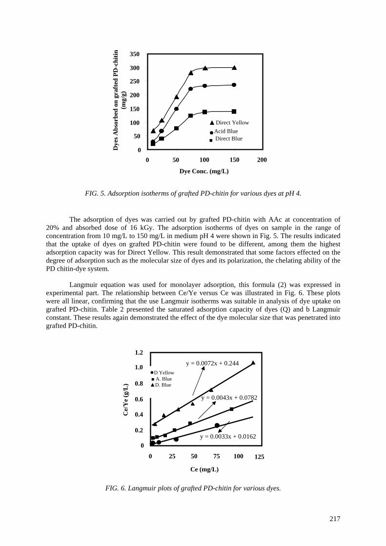
0
50
100
150
200
250
300
350
0 50 100 150 200
Dye Conc. (mg/L)
Dye
s Abs
orbe
d on
gra
fted
PD
-chi
tin
(mg/
g)
▲ Direct Yellow
● Acid Blue
■ Direct Blue
FIG. 5. Adsorption isotherms of grafted PD-chitin for various dyes at pH 4.
The adsorption of dyes was carried out by grafted PD-chitin with AAc at concentration of 20% and absorbed dose of 16 kGy. The adsorption isotherms of dyes on sample in the range of concentration from 10 mg/L to 150 mg/L in medium pH 4 were shown in Fig. 5. The results indicated that the uptake of dyes on grafted PD-chitin were found to be different, among them the highest adsorption capacity was for Direct Yellow. This result demonstrated that some factors effected on the degree of adsorption such as the molecular size of dyes and its polarization, the chelating ability of the PD chitin-dye system.
Langmuir equation was used for monolayer adsorption, this formula (2) was expressed in experimental part. The relationship between Ce/Ye versus Ce was illustrated in Fig. 6. These plots were all linear, confirming that the use Langmuir isotherms was suitable in analysis of dye uptake on grafted PD-chitin. Table 2 presented the saturated adsorption capacity of dyes (Q) and b Langmuir constant. These results again demonstrated the effect of the dye molecular size that was penetrated into grafted PD-chitin.
y = 0.0072x + 0.244
y = 0.0043x + 0.0782
y = 0.0033x + 0.01620
0.2
0.4
0.6
0.8
1.2
0 25 50 75 100 125
Ce (mg/L)
Ce/
Ye
(g/L
)
1.0 ●D Yellow ■ A. Blue ▲D. Blue
FIG. 6. Langmuir plots of grafted PD-chitin for various dyes.
217
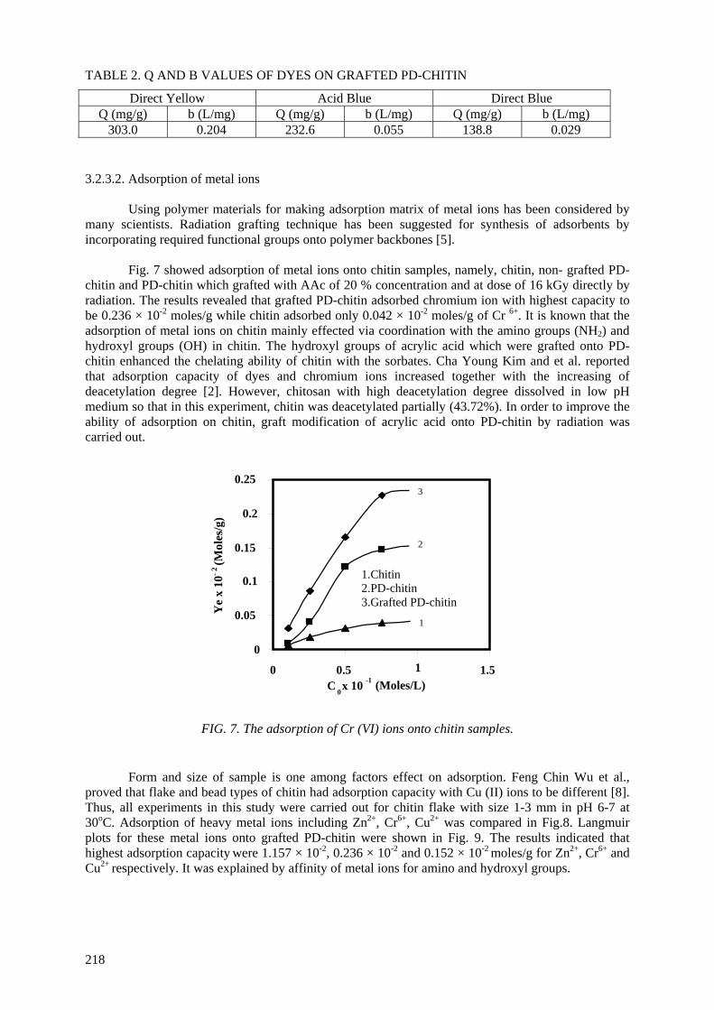
TABLE 2. Q AND B VALUES OF DYES ON GRAFTED PD-CHITIN
Direct Yellow Acid Blue Direct Blue Q (mg/g) b (L/mg) Q (mg/g) b (L/mg) Q (mg/g) b (L/mg)
303.0 0.204 232.6 0.055 138.8 0.029 3.2.3.2. Adsorption of metal ions
Using polymer materials for making adsorption matrix of metal ions has been considered by many scientists. Radiation grafting technique has been suggested for synthesis of adsorbents by incorporating required functional groups onto polymer backbones [5].
Fig. 7 showed adsorption of metal ions onto chitin samples, namely, chitin, non- grafted PD-
chitin and PD-chitin which grafted with AAc of 20 % concentration and at dose of 16 kGy directly by radiation. The results revealed that grafted PD-chitin adsorbed chromium ion with highest capacity to be 0.236 × 10⁻² moles/g while chitin adsorbed only 0.042 × 10⁻² moles/g of Cr 6+. It is known that the adsorption of metal ions on chitin mainly effected via coordination with the amino groups (NH2) and hydroxyl groups (OH) in chitin. The hydroxyl groups of acrylic acid which were grafted onto PD-chitin enhanced the chelating ability of chitin with the sorbates. Cha Young Kim and et al. reported that adsorption capacity of dyes and chromium ions increased together with the increasing of deacetylation degree [2]. However, chitosan with high deacetylation degree dissolved in low pH medium so that in this experiment, chitin was deacetylated partially (43.72%). In order to improve the ability of adsorption on chitin, graft modification of acrylic acid onto PD-chitin by radiation was carried out.
0
0.05
0.1
0.15
0.2
0.25
0 0.5 1 1.5C
0x 10 -1 (Moles/L)
Ye
x 10
- 2 (M
oles
/g)
3
2
1
1.Chitin 2.PD-chitin 3.Grafted PD-chitin
FIG. 7. The adsorption of Cr (VI) ions onto chitin samples.
Form and size of sample is one among factors effect on adsorption. Feng Chin Wu et al., proved that flake and bead types of chitin had adsorption capacity with Cu (II) ions to be different [8]. Thus, all experiments in this study were carried out for chitin flake with size 1-3 mm in pH 6-7 at 30oC. Adsorption of heavy metal ions including Zn2+, Cr6+, Cu2+ was compared in Fig.8. Langmuir plots for these metal ions onto grafted PD-chitin were shown in Fig. 9. The results indicated that highest adsorption capacity were 1.157 × 10⁻², 0.236 × 10⁻² and 0.152 × 10⁻² moles/g for Zn2+, Cr6+ and Cu2+ respectively. It was explained by affinity of metal ions for amino and hydroxyl groups.
218
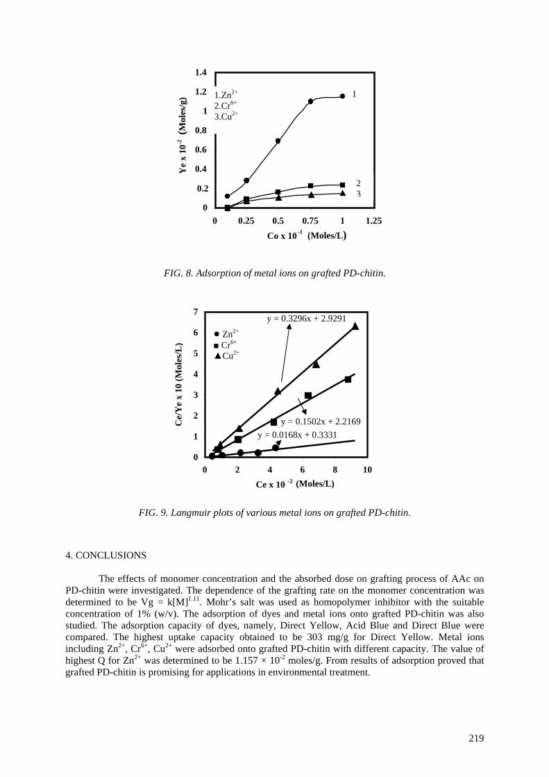
FIG. 8. Adsorption of metal ions on grafted PD-chitin.
0
0.2
0.4
0.6
0.8
1
1.2
1.4
0 0.25 0.5 0.75 1 1.25Co x 10 -1
(Moles/L)
(Mol
es/g
) 1
Ye
x 10
-2
2 3
1.Zn2+ 2.Cr6+
3.Cu2+
FIG. 9. Langmuir plots of various metal ions on grafted PD-chitin.
y = 0.3296x + 2.9291
y = 0.1502x + 2.2169 y = 0.0168x + 0.3331
0
1
2
3
4
5
6
7
0 2 4 6 8 10Ce x 10 -2 (Moles/L)
Ce/
Ye
x 10
(Mol
es/L
)
● Zn2+ ■ Cr6+ ▲Cu2+
4. CONCLUSIONS
The effects of monomer concentration and the absorbed dose on grafting process of AAc on PD-chitin were investigated. The dependence of the grafting rate on the monomer concentration was determined to be Vg = k[M]1.11. Mohr’s salt was used as homopolymer inhibitor with the suitable concentration of 1% (w/v). The adsorption of dyes and metal ions onto grafted PD-chitin was also studied. The adsorption capacity of dyes, namely, Direct Yellow, Acid Blue and Direct Blue were compared. The highest uptake capacity obtained to be 303 mg/g for Direct Yellow. Metal ions including Zn2+, Cr6+, Cu2+ were adsorbed onto grafted PD-chitin with different capacity. The value of highest Q for Zn2+ was determined to be 1.157 × 10⁻² moles/g. From results of adsorption proved that grafted PD-chitin is promising for applications in environmental treatment.
219
REFERENCES
[1] LIM, L.Y., et al., J. Biomed. Mater. Res. (Appl. Biomater.) 43 (1998) 282-290. [2] KIM, C. Y., et al., J. Appl. Polym. Sci. 63 (1997) 725-736. [3] DON, T.M., et al., Polymer Journal 34 (2002) 418-425. [4] TAKACS, E., et al., 6th International Symposium on Ionizing Radiation and Polymers (2004)
001. [5] TAMADA, M., IAEA- TECDOC-1422 (2004) 17-20. [6] BRUGNEROTTO, J., et al., Polymer 42 (2001) 3569-3580. [7] TASHER, N.H., et al., Radiat. Phys. Chem. 36 (1990), 785-790. [8] WU, F.C., et al., Journal of Hazardous Materials B73 (2000) 63-75.
220

PUBLICATIONS OF PARTICIPANTS IN THE CRP DURING THE COURSE OF THE PROJECT
BRAZIL MOURA, E.A.B.; ORTIZ, A.V., WIEBECK, H., PAULA, A.B.A., SILVA, A.L.A., SILVA, L.G.A., Effects of gamma radiation on commercial food packaging films – study of changes in UV/VIS spectra. Radiat. Phys. Chem., 71 (2004) 201-204.
PAULA, A.B.A., MOURA, E.A.B., ORTIZ, A.V., WIEBECK, H., SILVA, L.G.A., Estudo comparateito da radiação ionizante sobre as proprieddes ópticas do filme flexível de Poliamida 6, 6.6. In: 7th. Meeting on Nuclear Applications, 2005, Santos. INAC 2005 International Nuclear Atlantic Conference (2005) CD-ROM.
MOURA, E.A.B., Evaluation of performance of food packaging when treated with ionizing radiation. Thesis of Ph D. – IPEN, Brazil (2006). BULGARIA MISHEVA, M., ZAMFIROVA, G., GAYDAROV, V., PEREÑA, J.M., CERRADA, M.L., PÉREZ, E., BENAVENTE, R., “Gamma irradiation effect on isotactic poly(propylene) studied by microhardness and positron annihilation lifetime methods”, to be submitted
MISHEVA, M., DJOURELOV, N., “Positron annihilation lifetime study of biodegradable poly(l-lactide), poly(dl-lactide), poly(l-lactide-co-dl-lactide), and poly(dl-lactide-co-glycolide), before and after gamma irradiation”, to be submitted
MISHEVA, M., DJOURELOV, N., ZAMFIROVA, G., GAYDAROV, V., CERRADA, M.L., RODRÍGUEZ-AMOR, V., PÉREZ, E., “Effect of compatibilizer and electron irradiation on free-volume and microhardness of syndiotactic polypropylene/clay nanocomposites”, in press, Radiat. Phys. Chem. (2007)
DJOURELOV, N., ATEŞ, Z., GÜVEN, O., MISHEVA, M., SUZUKI, T., “Positron annihilation lifetime spectroscopy of molecularly imprinted hydoxyethyl methacrylate based polymers” Polymer, 48 (2007) 2692-2699. EGYPT ABDEL-MOHDY, H.L., HEGAZY, E.A., ABDEL-REHIM, H., “Characterization of Strach /Acrylic Acid Super-Absorbent Hydrogels Prepared by Ionizing Radiation” J Macromol. Sci., Appl. Chem. 43 (2006) 1051-1063.
ABD EL-REHIM, H., “Characterization and Possible Agricultural Application of Polyacrylamide/Sodium Alginate Crosslinked Hydrogels Prepared by Ionizing Radiation”, J Appl. Polym. Science, 101 (2006) 3572–3580.
ABD EL-REHIM, H., “Characterization and Possible Agricultural Application of Polyacrylamide/Sodium Alginate Crosslinked Hydrogels Prepared by Ionizing Radiation”, J Appl. Polym. Science, 102 (2006) 6088–6090.
KAMAL, H., GILANE M.S., LOTFY, S., ABDALLAH, N.M., ULANSKI, P., ROSIAK, J., and HEGAZY, E.A., “Controlling of Degradation Effects in Radiation Processing of Starch” J Macromolecular Science Part A: Pure and Applied Chemistry 44 (2007) 865–875.
ABDEL-REHIM, H., HEGAZY, E.A., ABDEL-MOHDY, H.L., “Effect of Various Environmental Conditions on the Swelling Property of PAAm/PAAcK Superabsorbent Hydrogel Prepared by Ionizing Radiation”, J Appl. Polym. Science, 101 (2006) 3955–3962.
221
KOREA, REPUBLIC OF LEE, S.H., NHO, Y.C., “Modification of Microsturctures and Physical Properties of Ultra High Molecular Weight Polyethylene by Electron Beam Irradiation”, J. Polymer Science, Polymer Physics, 43 (2005) 3019-3029.
KIM, S.S., KANG, P.H., NHO, Y.C., YANG, O.B., “Effect of electron beam irradiation on physical properties of ultra high molecular weight polyethylene”, J. Applied Polymer Science, 97 (2005) 103-116.
LIM, Y.M., NHO, Y.C., “Radiation Effect on Poly(ε-caprolactone)Nanofibrous Scaffold”, Solid State Phenomena, 119(2007) 95-98.
JEUN, J.P., LIM, Y.M., NHO, Y.C., Study on Morphology of Electrospun Poly(carprolactone) Nanofiber, J. Ind. Eng. Chem., 11 (2005) 573-578. POLAND PRZYBYTNIAK, G., MIRKOWSKI, K., RAFALSKI, A., NOWICKI, A., KORNACKA, E., ”Radiation degradation of blends polypropylene/poly(ethylene-co-vinyl acetate)” Radiat. Phys. Chem.76 (2007) 1312-1317.
PRZYBYTNIAK, G., MIRKOWSKI, K., RAFALSKI, A., NOWICKI, A., LEGOCKA, I., ZIMEK, Z., ”Effect of hindered amine light stabilizers on resistance of polypropylene towards ionizing radiation” Nukleonika, 50 (2005)153-159. ROMANIA
ZAHARESCU, T., FERARU, E., PODINĂ, C., ”Thermal stabiliy of ethylene propylene-diene monomer/divinylbenzene systems” Polym. Degrad. Stabil., 87 (2005)11-16
ZAHARESCU, T., JIPA, S., KAPPEL, W., SUPAPHOL, P., ”The Control of Thermal and Radiation Stability of Polypropylene Containing Calcium Carbonate Nanoparticles”, Macromol. Symp., 242 (2006) 319-324.
ZAHARESCU, T., JIPA, S., GIGANTE, B., ”Radiation effects on stabilized LDPE”
Polym. Bulletin, 57 (2006)729–735.
ZAHARESCU, T., FERARU, E., PODINĂ, C., JIPA, S., “Modifications of EPDM by gamma irradiation in hydrocarbon environment”, Polym. Degrad. Stabil., 89 (2005) 373-381.
ZAHARESCU, T., JIPA, S., SETNESCU, R., SETNESCU, T., DUMITRU, M., “Radiochemical degradation of EPDM/PP compounds”, Nucl. Instr. and Meth., submitted (the contribution to IRaP 2006 Conference, Antalya, September 23-38) TURKEY ŞEN, M., TOPRAK, D., GÜVEN, O., “The Use of Radiation-Induced Degradation in Controlling Molecular Weights of Polysaccharides: The Effect of Humidity”, 7th International Symposium on Ionizing Radiation and Polymers (IRaP2006), 23 – 28 September 2006, Antalya, Turkey
KARAAĞAÇ, B., ŞEN, M., DENIZ, V., GÜVEN, O., “Recycling of Gamma Irradiated Inner Tubes in Butyl Based Rubber Compounds”, 7th International Symposium on Ionizing Radiation and Polymers (IRaP2006), 23 – 28 September 2006, Antalya, Turkey.
TAHTAT, D., UZUN, C., MAHLOUS, M., GÜVEN, O., “Effect of Gamma Irradiation on the Deacetylation of Chitin to Form Chitosan”, 7th International Symposium on Ionizing Radiation and Polymers (IRaP2006), 23 – 28 September, Turkey.
222

YOLAÇAN, B., SEN, M., GÜVEN, O., “Radiation-Induced Degradation of Galactomannan Polysaccharides”, 7th International Symposium on Ionizing Radiation and Polymers (IRaP2006), 23 – 28 September, Antalya, Turkey.
BODUGÖZ, H., GÜVEN, O., “Radiation-induced dehydrochlorination as an in-situ doping technique for the enhancement of conductivity of polyaniline blends” Nuclear Inst. & Meth. Phys. Res. B, 236 (2005) 153-159.
DJOURELOV, N., ATEŞ. Z., GÜVEN, O., MISHEVA, M., SUZUKI, T., “Positron annihilation lifetime spectroscopy of molecularly imprinted hydoxyethyl methacrylate based polymers” Polymer, 48 (2007) 2692-2699. SPAIN CERRADA, M.L., PÉREZ, E., FERNÁNDEZ-BLÁZQUEZ, J.P., ÁLVAREZ, C., LÓPEZ-MAJADA, J.M., ARRANZ-ANDRÉS, J., HERMIDA, I., BELLO, A., BENAVENTE, R., PEREÑA, J.M., DOMMACH, M., FUNARI, S., "Polymorphism in conventional iPP by effect of gamma radiation" Hasylab Annual Report (2003) 947-948.
CERRADA, M.L., PÉREZ, E., FERNÁNDEZ-BLÁZQUEZ, J. P., LÓPEZ-MAJADA, J.M., ARRANZ-ANDRÉS, J., HERMIDA, I., BELLO, A., BENAVENTE, R., PEREÑA, J.M., DOMMACH, M., FUNARI, S., RODRÍGUEZ-AMOR, V., "Preliminary analysis of gamma irradiation effect on syndiotactic polypropylene"Hasylab Annual Report (2006)1195-1196.
CERRADA, M.L., RODRÍGUEZ-AMOR, V., PÉREZ, E., "Effect of clay nanoparticles and electron irradiation in the crystallization of syndiotactic polypropylene" J. Polym. Sci. Part B: Polym. Phys. 45 (2007) 1068-1076. UNITED STATES OF AMERICA MOWERY, D.M., ASSINK, R.A., DERZON, D.K., KLAMO, S.B., CLOUGH, R.L., BERNSTEIN, R., “Solid-State 13C NMR Investigation of the Oxidative Degradation of Selectively Labeled Polypropylene by Thermal Aging and Gamma-Irradiation” Macromolecules. 38 (2005) 5035-5046.
MOWERY, D.M., ASSINK, R.A., DERZON, D.K., KLAMO, S.B., BERNSTEIN, R., CLOUGH, R.L., “Radiation Oxidation of Polypropylene: A Solid-State 13C NMR Study Using Selective Isotopic Labeling” Radiation Physics and Chemistry (in press).
THORNBERG, S.M., BERNSTEIN, R., DERZON, D.K., IRWIN, A.N., KLAMO, S.B., CLOUGH, R.L., “The Genesis of CO2 and CO in the Thermooxidative Degradation of Polypropylene. Polymer Degradation and Stability” (in press).
BERNSTEIN, R., THORNBERG, S.M., ASSINK, R.A., MOWERY, D.M., ALAM, M.K., IRWIN, A.N., HOCHREIN, M., DERZON, D.K., KLAMO, S.B., CLOUGH, R.L., “Insights into Oxidation Mechanisms in Gamma-Irradiated Polypropylene, Utilizing Selective Isotopic Labeling with Analysis by GC/MS, NMR and FTIR” Nuclear Instruments and Methods [NIMB] (submitted).
223


LIST OF PARTICIPANTS
CLOUGH, R. Sandia National Laboratories Organic Materials Aging and Reliability Department M.S. 0888, Albuquerque, NM 871785, USA
GUEVEN O. Dept. of Chemistry, Hacettepe University, Beytepe,
06532 Ankara, Turkey HEGAZY, E.-S. National Centre for Radiation Research and Technology
3 Ahmed EI-Zomor Street, POB 29, Nasr City, Cairo, Egypt MACKOVÁ, A. Nuclear Physics Institute (NPI), Academy of Sciences of the Czech Republic, Husinec-Rez, cp. 30, 250 68 Rez, Czech Republic MISHEVA, M. Faculty of Physics, St. Kliment Ohridski University of Sofia
5, James Bourchier blvd, BG-1164 Sofia, Bulgaria NHO, Y.-C. Korea Atomic Energy Research Institute (KAERI)
1266 Sinjeongdong, Jeongup, Chondong 580-195 Daejon 305-600, Republic of Korea
PÉREZ, E. Instituto de Ciencia y Tecnología de Polímeros (CSIC),
Juan de la Cierva 3, 28006-Madrid, Spain TRUONG, T.H. Research and Development Center for Radiation Technology
(VINGAMMA), Truong Tre St., Linh Xuan Ward, Thu Duc Dist., Ho Chi Minh City, Vietnam
SILVA, L.G.A. Instituto de Pesquisas Energéticas e Nucleares (IPEN) Centro de Tecnologia das Radiações – CTR Av. Prof. Lineu Prestes, 2242 Cidade Universitaria 05508-000 Sao Paulo, Cidade Universitaria - Butantã Estado de São Paulo, Brazil
YASIN, T. Advanced Polymer Laboratory,
Pakistan Institute of Engineering and Applied Sciences (PIEAS) Pakistan Atomic Energy Commission (PAEC) PO. Nilore, Islamabad, Pakistan
ZAHARESCU, T. Advanced Research Institute for Electrical Engineering 313
Splaiul Unirii, P.O.B. 87, Bucharest 030138, Romania ZIMEK, Z.A. Institute of Nuclear Chemistry and Technology
Department of Radiation Chemistry and Technology Dorodna 16 Str. 03-195, Warsaw, Poland
Research Coordination Meetings
Vienna, Austria: 8–11 December 2003
Madrid, Spain: 11–15 July 2005 Daejeon, Republic of Korea: 4–8 December 2006
22 5


![Mitotic degradation of yeast Fkh1 by the Anaphase ......transcription factors that are critical for properly controlling apoptosis, autophagy, metabolism and cell proliferation [10-12]](https://img.pdfslide.us/doc/110x75/5ebaa24fda0be951b03415a0/mitotic-degradation-of-yeast-fkh1-by-the-anaphase-transcription-factors.jpg)