Embed Size (px)
Citation preview
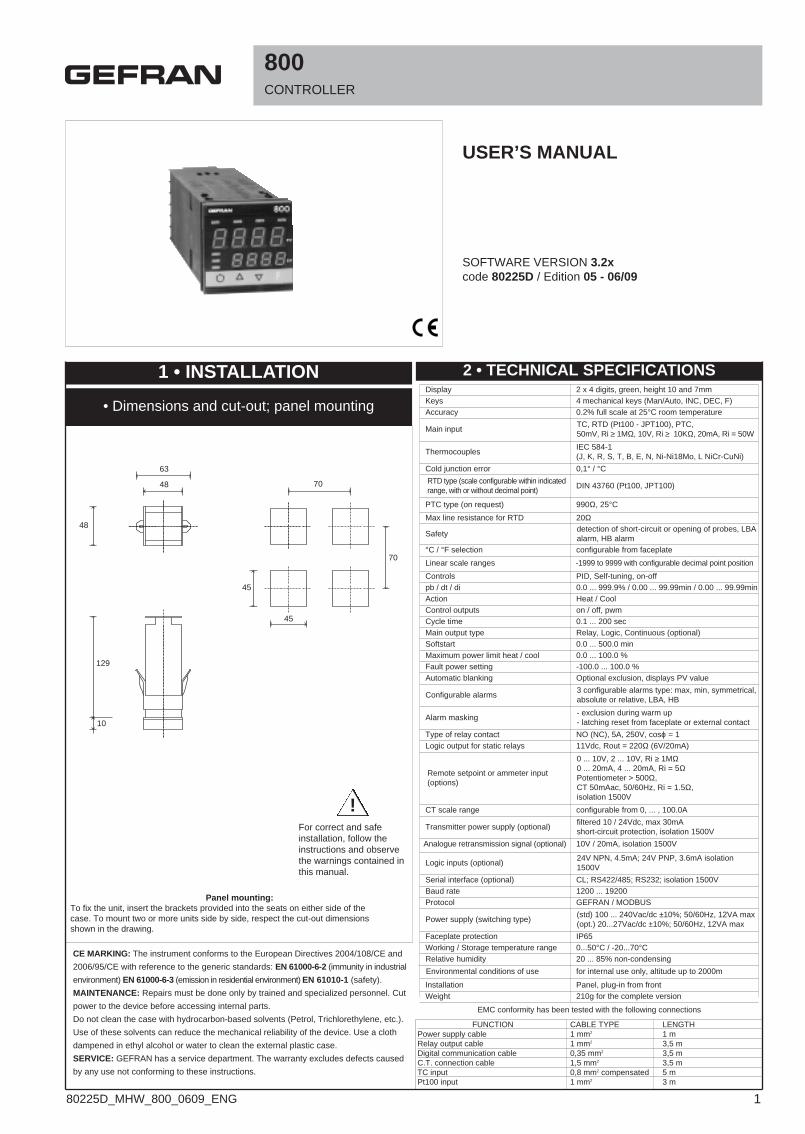
RTD type (scale configurable within indicatedrange, with or without decimal point)
PTC type (on request)
DIN 43760 (Pt100, JPT100)
990Ω, 25°C
Max line resistance for RTD 20Ω
Safetydetection of short-circuit or opening of probes, LBAalarm, HB alarm
°C / °F selection configurable from faceplate
Linear scale ranges -1999 to 9999 with configurable decimal point position
800CONTROLLER
SOFTWARE VERSION 3.2xcode 80225D / Edition 05 - 06/09
USER’S MANUAL
ThermocouplesIEC 584-1(J, K, R, S, T, B, E, N, Ni-Ni18Mo, L NiCr-CuNi)
Cold junction error 0,1° / °C
Controls PID, Self-tuning, on-offpb / dt / di 0.0 ... 999.9% / 0.00 ... 99.99min / 0.00 ... 99.99minAction Heat / CoolControl outputs on / off, pwmCycle time 0.1 ... 200 secMain output type Relay, Logic, Continuous (optional)Softstart 0.0 ... 500.0 minMaximum power limit heat / cool 0.0 ... 100.0 %Fault power setting -100.0 ... 100.0 %Automatic blanking Optional exclusion, displays PV value
Configurable alarms3 configurable alarms type: max, min, symmetrical,absolute or relative, LBA, HB
Alarm masking- exclusion during warm up- latching reset from faceplate or external contact
Type of relay contact NO (NC), 5A, 250V, cosϕ = 1
48
63
48
129
10
45
45
70
70
For correct and safeinstallation, follow theinstructions and observethe warnings contained inthis manual.
Faceplate protection IP65Working / Storage temperature range 0...50°C / -20...70°CRelative humidity 20 ... 85% non-condensing
Installation Panel, plug-in from frontWeight 210g for the complete version
Main inputTC, RTD (Pt100 - JPT100), PTC, 50mV, Ri ≥ 1MΩ, 10V, Ri ≥ 10KΩ, 20mA, Ri = 50W
CT scale range configurable from 0, ... , 100.0A
Transmitter power supply (optional)filtered 10 / 24Vdc, max 30mAshort-circuit protection, isolation 1500V
Analogue retransmission signal (optional) 10V / 20mA, isolation 1500V
Logic inputs (optional)24V NPN, 4.5mA; 24V PNP, 3.6mA isolation1500V
Serial interface (optional) CL; RS422/485; RS232; isolation 1500VBaud rate 1200 ... 19200Protocol GEFRAN / MODBUS
Logic output for static relays 11Vdc, Rout = 220Ω (6V/20mA)
Remote setpoint or ammeter input(options)
0 ... 10V, 2 ... 10V, Ri ≥ 1MΩ0 ... 20mA, 4 ... 20mA, Ri = 5ΩPotentiometer > 500Ω,CT 50mAac, 50/60Hz, Ri = 1.5Ω,isolation 1500V
Power supply (switching type)(std) 100 ... 240Vac/dc ±10%; 50/60Hz, 12VA max(opt.) 20...27Vac/dc ±10%; 50/60Hz, 12VA max
Display 2 x 4 digits, green, height 10 and 7mmKeys 4 mechanical keys (Man/Auto, INC, DEC, F)Accuracy 0.2% full scale at 25°C room temperature
1 • INSTALLATION
• Dimensions and cut-out; panel mounting
Panel mounting:To fix the unit, insert the brackets provided into the seats on either side of thecase. To mount two or more units side by side, respect the cut-out dimensionsshown in the drawing.
CE MARKING: The instrument conforms to the European Directives 2004/108/CE and
2006/95/CE with reference to the generic standards: EN 61000-6-2 (immunity in industrial
environment) EN 61000-6-3 (emission in residential environment) EN 61010-1 (safety).
MAINTENANCE: Repairs must be done only by trained and specialized personnel. Cut
power to the device before accessing internal parts.
Do not clean the case with hydrocarbon-based solvents (Petrol, Trichlorethylene, etc.).
Use of these solvents can reduce the mechanical reliability of the device. Use a cloth
dampened in ethyl alcohol or water to clean the external plastic case.
SERVICE: GEFRAN has a service department. The warranty excludes defects caused
by any use not conforming to these instructions.
2 • TECHNICAL SPECIFICATIONS
FUNCTION CABLE TYPE LENGTHPower supply cable 1 mm2 1 mRelay output cable 1 mm2 3,5 mDigital communication cable 0,35 mm2 3,5 mC.T. connection cable 1,5 mm2 3,5 mTC input 0,8 mm2 compensated 5 mPt100 input 1 mm2 3 m
EMC conformity has been tested with the following connections
!
Environmental conditions of use for internal use only, altitude up to 2000m
180225D_MHW_800_0609_ENG
Use wires ofadequatediameter
(min. 1mm2)PT100,
JPT100, PTC
• Pt100 3-wires
3
1
2
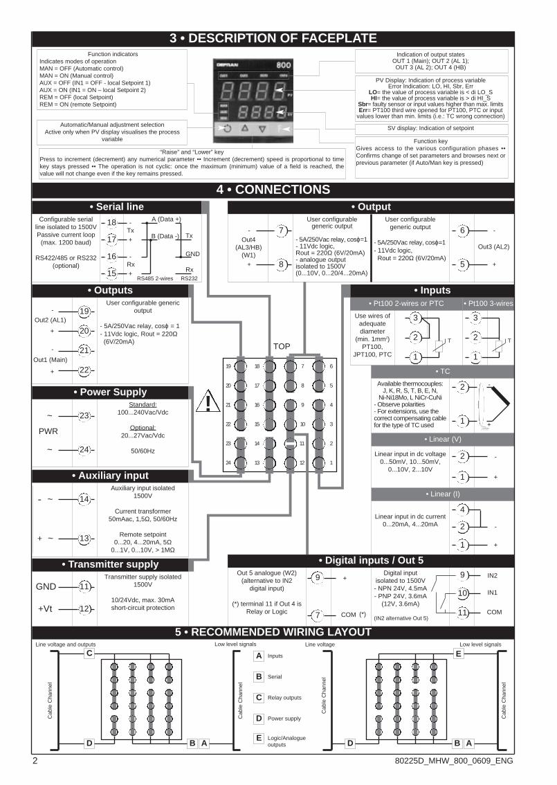
“Raise” and “Lower” keyPress to increment (decrement) any numerical parameter •• Increment (decrement) speed is proportional to timekey stays pressed •• The operation is not cyclic: once the maximum (minimum) value of a field is reached, thevalue will not change even if the key remains pressed.
3 • DESCRIPTION OF FACEPLATE
Automatic/Manual adjustment selectionActive only when PV display visualises the process
variable
PV Display: Indication of process variableError Indication: LO, HI, Sbr, Err
LO= the value of process variable is < di LO_SHI= the value of process variable is > di HI_S
Sbr= faulty sensor or input values higher than max. limitsErr= PT100 third wire opened for PT100, PTC or input
values lower than min. limits (i.e.: TC wrong connection)
Function keyGives access to the various configuration phases ••Confirms change of set parameters and browses next orprevious parameter (if Auto/Man key is pressed)
Function indicatorsIndicates modes of operationMAN = OFF (Automatic control)MAN = ON (Manual control)AUX = OFF (IN1 = OFF - local Setpoint 1)AUX = ON (IN1 = ON – local Setpoint 2)REM = OFF (local Setpoint)REM = ON (remote Setpoint)
SV display: Indication of setpoint
Indication of output statesOUT 1 (Main); OUT 2 (AL 1);OUT 3 (AL 2); OUT 4 (HB)
User configurablegeneric output
- 5A/250Vac relay, cosϕ=1- 11Vdc logic,Rout = 220Ω (6V/20mA)
Configurable serialline isolated to 1500VPassive current loop
(max. 1200 baud)
RS422/485 or RS232(optional)
Standard:100...240Vac/Vdc
Optional:20...27Vac/Vdc
50/60Hz
Digital inputisolated to 1500V- NPN 24V, 4.5mA- PNP 24V, 3.6mA
(12V, 3.6mA)
Linear input in dc current0...20mA, 4...20mA
• Digital inputs / Out 5
4 • CONNECTIONS
• Outputs
+
-
User configurable genericoutput
- 5A/250Vac relay, cosϕ = 1- 11Vdc logic, Rout = 220Ω(6V/20mA)
• Serial line
Available thermocouples:J, K, R, S, T, B, E, N,
Ni-Ni18Mo, L NiCr-CuNi- Observe polarities- For extensions, use thecorrect compensating cablefor the type of TC used
18
17
16
15
-
+
-
+
Tx
Rx
• TC 6
5
4
3
2
1
7
8
9
10
11
12
18
17
16
15
14
13
19
20
21
22
23
24
2
1
Linear input in dc voltage0...50mV, 10...50mV,
0...10V, 2...10V
2
1 +
-
• Linear (I)
4
1
2 -
+
9
11
10
19
21
20
22
-
+
Out2 (AL1)
-
+
Out1 (Main)
IN1
IN2
COM
• Power Supply
Transmitter supply isolated1500V
10/24Vdc, max. 30mAshort-circuit protection
23
24
~
~
• Transmitter supply
11
12
GND
+Vt
Auxiliary input isolated1500V
Current transformer50mAac, 1,5Ω, 50/60Hz
Remote setpoint0...20, 4...20mA, 5Ω
0...1V, 0...10V, > 1MΩ
• Auxiliary input
14
13
~
~
• OutputUser configurable
generic output
- 5A/250Vac relay, cosϕ=1- 11Vdc logic,Rout = 220Ω (6V/20mA)- analogue outputisolated to 1500V(0...10V, 0...20/4...20mA)
6
5 +
-
Out3 (AL2)
7
8+
-Out4
(AL3/HB)(W1)
Out 5 analogue (W2)(alternative to IN2
digital input)
(*) terminal 11 if Out 4 isRelay or Logic
9
7
+
COM (IN2 alternative Out 5)
TOP
5 • RECOMMENDED WIRING LAYOUT
A
B
C
D
Inputs
Serial
Relay outputs
Power supply
AD B
Low level signalsLine voltage and outputs
A
E
D B
Low level signalsLine voltage
E Logic/Analogueoutputs
C
Cab
le C
hann
el
Cab
le C
hann
el
Cab
le C
hann
el
Cab
le C
hann
el
-
+
(*)
PWR
!
A (Data +)
B (Data -)
RS485 2-wires
• Pt100 2-wires or PTC
3
1
2
• Inputs
TT
GND
RS232
Tx
Rx
• Linear (V)
2 80225D_MHW_800_0609_ENG
ts
inp.2
al.1
al.2
al.3
al.xb
0Vt.P
sp
SP.1
SP.2
SP.3
212
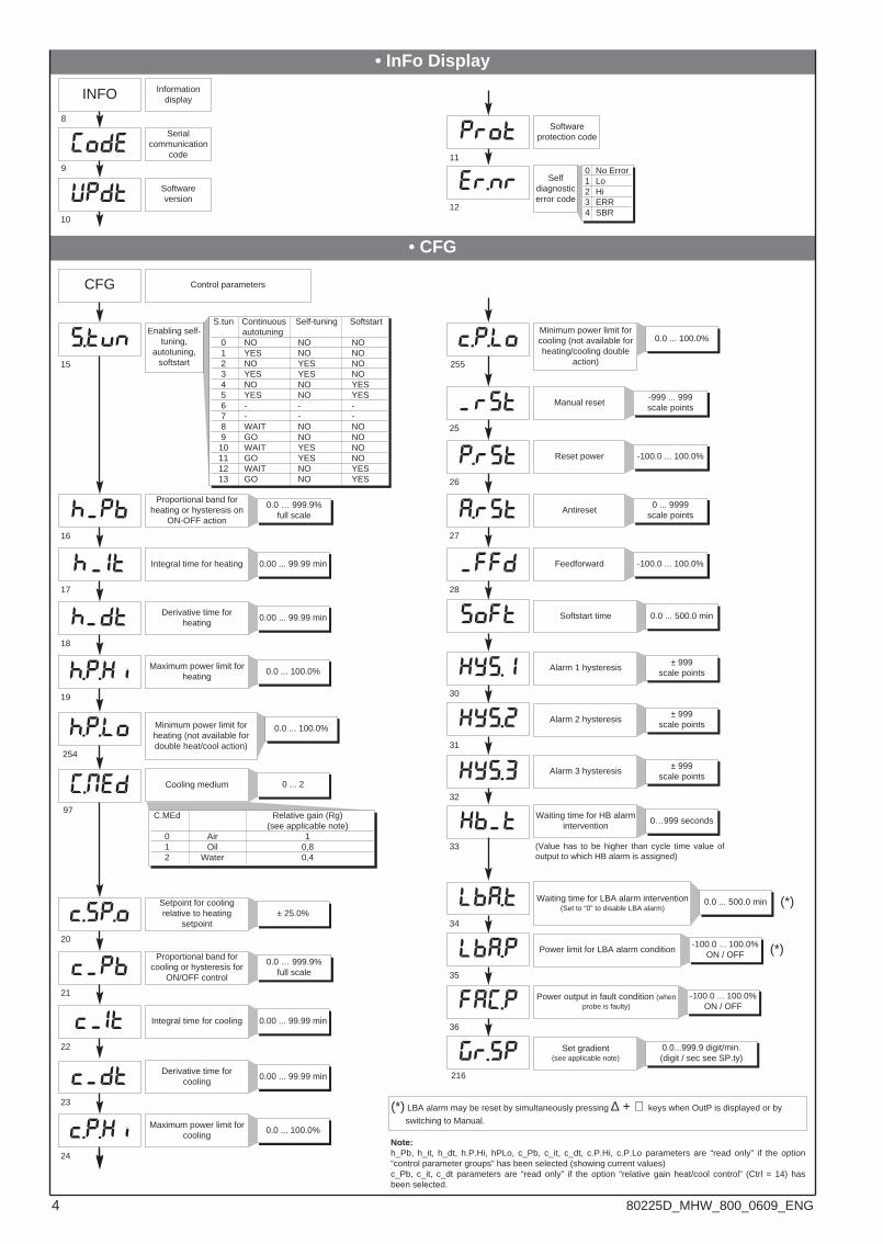
5 • PROGRAMMING and CONFIGURATION
F
If Inc, Dec, F keys are not pressed within 30 sec, display returns automatically to PV/SV value.All INFO and dAtA data on config menu remain displayed and are not timed.
INFO
P.V. / S.V. Process variable (PV display)Work Setpoint (SV display) or controloutput value with regulator in manual
Amperometric input value or remoteSetpoint (with auxiliary input
enabled)
Alarm point 1 (scale points)
Alarm point 2 (scale points)
Alarm point 3 (scale points)
Heater break alarm point (scalepoints of ammeter input)
Control output value(+Heat / -Cool)
Press forapprox.2 sec
Control parameters
dAtA
CFG
SEr
InP
Out
PASS = 99
Prot
Lin
CuSt
Serial communications
Input settings
Output settings
Hardware configuration
Input linearization
“dAtA” menu setting
_CAL Select calibration menu [ 0...12 ]
YES
NO
Keep the F keypressed to scroll
the menus
Release the F keyto select the
displayed menu
Press the F key toaccess theparameters
Keep the F keypressed to exit any
menu
Keep F + Auto/Mankeys pressed for 2sec. on any menuto go immediatelyto level 1 display
(*)
(*)
S3 = ON
Local Setpoint
LEVEL 1 MENU
PASS
NO
YES
Hrd
U.CAL
S4 = ON
YES
NO
Custom menu
Password
User calibration
Protection code
(*) The automatic return PV/SV display is disabled for these displays
1
2
3
4
5
6
7
Information display
Setpoint 1
Setpoint 2
Setpoint 3
Setpoint 4
Limit value of timer0 ... 9999 sec
SP.4
N.B.: Once a particular configuration is entered, all unnecessary parameters are no longer displayed
213
214
215
217
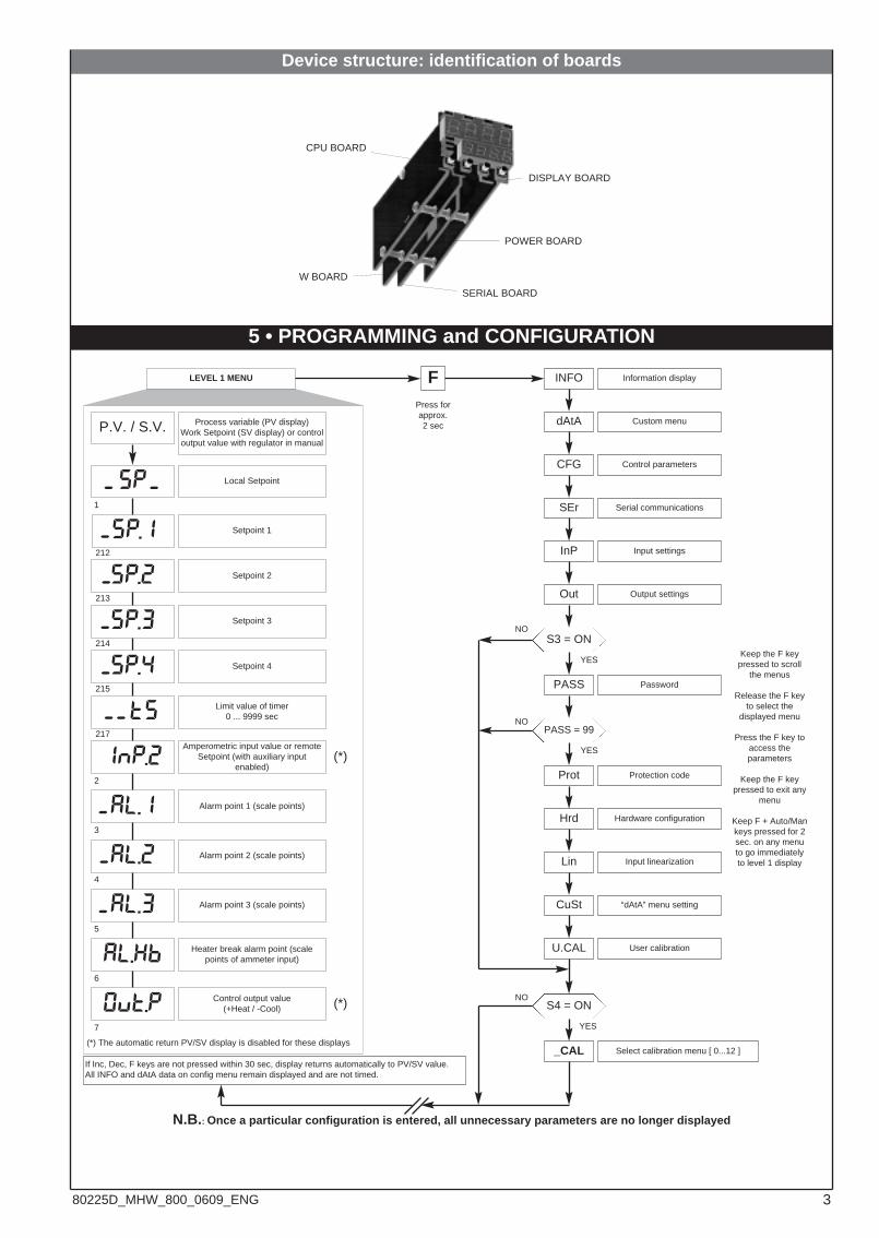
Device structure: identification of boards
- -
-
-
-
-
--
-
-
-
DISPLAY BOARD
POWER BOARD
CPU BOARD
W BOARD
SERIAL BOARD
380225D_MHW_800_0609_ENG
(ode
updt
S.tvn
h pb
h it
h dt
h.p.xi
h.p.lo
c.sp.o
c pb
c it
c dt
c.p.x1
er.nr
c.p.lo
rst
P.rst
A.rst
ffd
soft
Xys.i
Xys.2
Xys.3
xb t
lba.t
lba.p
fa(.p
gr.sp
prot
• InFo Display
• CFG
Enabling self-tuning,
autotuning,softstart
CFG Control parameters
Proportional band forheating or hysteresis on
ON-OFF action
Integral time for heating
Derivative time forheating
Maximum power limit forheating
Setpoint for coolingrelative to heating
setpoint
Proportional band forcooling or hysteresis for
ON/OFF control
Integral time for cooling
Derivative time forcooling
Maximum power limit forcooling
Manual reset
Alarm 2 hysteresis
Alarm 3 hysteresis
Waiting time for HB alarmintervention
Waiting time for LBA alarm intervention(Set to “0” to disable LBA alarm)
Power limit for LBA alarm condition
Power output in fault condition (whenprobe is faulty)
(*)
(*)
15
16
17
18
19
20
21
22
23
24
25
31
32
33
34
35
36
S.tun Continuous Self-tuning Softstartautotuning
0 NO NO NO1 YES NO NO2 NO YES NO3 YES YES NO4 NO NO YES5 YES NO YES6 - - -7 - - -8 WAIT NO NO9 GO NO NO10 WAIT YES NO11 GO YES NO12 WAIT NO YES13 GO NO YES
0.00 ... 99.99 min
0.00 ... 99.99 min
0.0 ... 100.0%
-999 ... 999scale points
0.0 … 999.9%full scale
0.00 ... 99.99 min
0.00 ... 99.99 min
0.0 ... 100.0%
± 25.0%
0.0 … 999.9%full scale
± 999scale points
± 999scale points
0…999 seconds
0.0 ... 500.0 min
-100.0 ... 100.0%ON / OFF
-100.0 ... 100.0%ON / OFF
Set gradient (see applicable note)
0.0...999.9 digit/min.(digit / sec see SP.ty)
Antireset
Feedforward
27
28
0 ... 9999scale points
-100.0 ... 100.0%
Reset power
26
-100.0 ... 100.0%
(*) LBA alarm may be reset by simultaneously pressing ∆ + ∇ keys when OutP is displayed or by
switching to Manual.
216
INFO
Serialcommunication
code
Softwareversion
Softwareprotection code
Selfdiagnosticerror code
8
9
10
11
12
Informationdisplay
0 No Error1 Lo2 Hi3 ERR4 SBR
Alarm 1 hysteresis
30
± 999scale points
Softstart time 0.0 ... 500.0 min
(Value has to be higher than cycle time value ofoutput to which HB alarm is assigned)
Minimum power limit forheating (not available fordouble heat/cool action)
254
0.0 ... 100.0%
Cooling medium
97
0 ... 2
C.MEd Relative gain (Rg)(see applicable note)
0 Air 11 Oil 0,82 Water 0,4
Minimum power limit forcooling (not available forheating/cooling double
action)255
0.0 ... 100.0%
Note:h_Pb, h_it, h_dt, h.P.Hi, hPLo, c_Pb, c_it, c_dt, c.P.Hi, c.P.Lo parameters are “read only” if the option“control parameter groups” has been selected (showing current values)c_Pb, c_it, c_dt parameters are “read only” if the option “relative gain heat/cool control” (Ctrl = 14) hasbeen selected.
-
-
-
(.MEd-
-
-
-
-
-
-
4 80225D_MHW_800_0609_ENG
(ode
ser.p
bavd
sp.ty
type
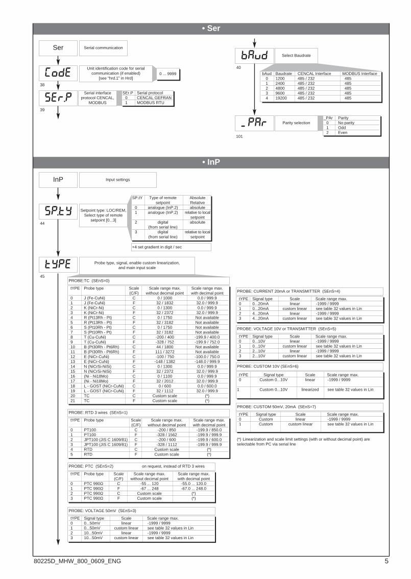
• Ser
Ser
Unit identification code for serialcommunication (if enabled)
[see “hrd.1” in Hrd]
Serial communication
Serial interfaceprotocol CENCAL,
MODBUS
Select Baudrate
38
39
40
0 ... 9999
SEr.P Serial protocol0 CENCAL GEFRAN1 MODBUS RTU
bAud Baudrate CENCAL Interface MODBUS Interface0 1200 485 / 232 4851 2400 485 / 232 4852 4800 485 / 232 4853 9600 485 / 232 4854 19200 485 / 232 485
Parity selection
101
_PAr Parity0 No parity1 Odd2 Even
Setpoint type: LOC/REM,Select type of remote
setpoint [0...3]
Probe type, signal, enable custom linearization,and main input scale
tYPE Probe type Scale Scale range max. Scale range max.(C/F) without decimal point with decimal point
0 J (Fe-CuNi) C 0 / 1000 0.0 / 999.91 J (Fe-CuNi) F 32 / 1832 32.0 / 999.92 K (NiCr-Ni) C 0 / 1300 0.0 / 999.93 K (NiCr-Ni) F 32 / 2372 32.0 / 999.94 R (Pt13Rh - Pt) C 0 / 1750 Not available5 R (Pt13Rh - Pt) F 32 / 3182 Not available6 S (Pt10Rh - Pt) C 0 / 1750 Not available7 S (Pt10Rh - Pt) F 32 / 3182 Not available8 T (Cu-CuNi) C -200 / 400 -199.9 / 400.09 T (Cu-CuNi) F -328 / 752 -199.9 / 752.010 B (Pt30Rh - Pt6Rh) C 44 / 1800 Not available11 B (Pt30Rh - Pt6Rh) F 111 / 3272 Not available12 E (NiCr-CuNi) C -100 / 750 -100.0 / 750.013 E (NiCr-CuNi) F -148 / 1382 -148.0 / 999.914 N (NiCrSi-NiSi) C 0 / 1300 0.0 / 999.915 N (NiCrSi-NiSi) F 32 / 2372 32.0 / 999.916 (Ni - Ni18Mo) C 0 / 1100 0.0 / 999.917 (Ni - Ni18Mo) F 32 / 2012 32.0 / 999.918 L - GOST (NiCr-CuNi) C 0 / 600 0.0 / 600.019 L - GOST (NiCr-CuNi) F 32 / 1112 32.0 / 999.920 TC C Custom scale (*)21 TC F Custom scale (*)
tYPE Probe type Scale Scale range max. Scale range max.(C/F) without decimal point with decimal point
0 PT100 C -200 / 850 -199.9 / 850.01 PT100 F -328 / 1562 -199.9 / 999.92 JPT100 (JIS C 1609/81) C -200 / 600 -199.9 / 600.03 JPT100 (JIS C 1609/81) F -328 / 1112 -199.9 / 999.94 RTD C Custom scale (*)5 RTD F Custom scale (*)
(*) Linearization and scale limit settings (with or without decimal point) areselectable from PC via serial line
PROBE: RTD 3 wires (SEnS=1)
PROBE: PTC (SEnS=2) on request, instead of RTD 3 wires
• InP
InP Input settings
44
45
SP.tY Type of remote Absolutesetpoint Relative
0 analogue (InP.2) absolute1 analogue (InP.2) relative to local
setpoint2 digital absolute
(from serial line)3 digital relative to local
(from serial line) setpoint
PROBE:TC (SEnS=0)
+4 set gradient in digit / sec
tYPE Probe type Scale Scale range max. Scale range max.(C/F) without decimal point with decimal point
0 PTC 990Ω C -55 ... 120 -55.0 ... 120.01 PTC 990Ω F -67 ... 248 -67.0 ... 248.02 PTC 990Ω C Custom scale (*)3 PTC 990Ω F Custom scale (*)
tYPE Signal type Scale Scale range max.0 0...50mV linear -1999 / 9999 1 0...50mV custom linear see table 32 values in Lin2 10...50mV linear -1999 / 99993 10...50mV custom linear see table 32 values in Lin
PROBE: VOLTAGE 50mV (SEnS=3)
tYPE Signal type Scale Scale range max.0 0...20mA linear -1999 / 99991 0...20mA custom linear see table 32 values in Lin2 4...20mA linear -1999 / 99993 4...20mA custom linear see table 32 values in Lin
PROBE: CURRENT 20mA or TRANSMITTER (SEnS=4)
tYPE Signal type Scale Scale range max.0 0...10V linear -1999 / 99991 0...10V custom linear see table 32 values in Lin2 2...10V linear -1999 / 99993 2...10V custom linear see table 32 values in Lin
PROBE: VOLTAGE 10V or TRANSMITTER (SEnS=5)
tYPE Signal type Scale Scale range max.0 Custom 0...10V linear -1999 / 9999
1 Custom 0...10V linearized see table 32 values in Lin
PROBE: CUSTOM 10V (SEnS=6)
tYPE Signal type Scale Scale range max.0 Custom linear -1999 / 99991 Custom custom linear see table 32 values in Lin
PROBE: CUSTOM 50mV, 20mA (SEnS=7)
par-
580225D_MHW_800_0609_ENG
xi l
lo l
of.52
xi.52
lo.52
flt.2filt
fild
dp s
lo s
xi s
ofst
tyP.2
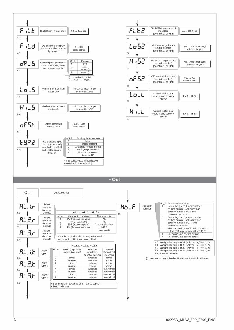
Digital filter on main input
Digital filter on displayprocess variable: acts as
hysteresis
Decimal point position formain input scale, alarm
and remote setpoint
(*) not available for TC,RTD and PTC scales
Minimum limit of maininput scale
Maximum limit of maininput scale
Offset correctionof main input
Digital filter on aux input(if enabled)
[see “hrd.1” on Hrd]
Aux analogue inputfunction (if enabled)[see “hrd.1” on Hrd]and enable custom
limitation
Minimum range for auxinput (if enabled)
[see “hrd.1” on Hrd]
Maximum range for auxinput (if enabled)
[see “hrd.1” on Hrd]
Offset correction of auxinput (if enabled)
[see “hrd.1” on Hrd]
Lower limit for localsetpoint and absolute
alarms
Upper limit for localsetpoint and absolute
alarms
+ 8 to select custom linearization(see table 32 values in Lin)
46
47
48
49
50
51
52
53
54
55
56
57
58
0.0 ... 20.0 sec
0 ... 9.9scale points
dP_S Format0 xxxx1 xxx.x2 xx.xx (*)3 x.xxx (*)
min...max input rangeselected in tyPE
min...max input rangeselected in tyPE
-999 ... 999scale points
tYP.2 Auxiliary input function0 None1 Remote setpoint2 Analogue remote manual3 Analogue power reset4 Current transformer
input for HB
0.0 ... 20.0 sec
Min…max input rangeselected in tyP.2
Min…max input rangeselected in tyP.2
-999 ... 999scale points
Lo.S ... Hi.S
Lo.S ... Hi.S
• Out
61
Out Output settings
Selectreferencesignal foralarm 1 AL.1.r, AL.2.r, AL.3.r
Selectreferencesignal foralarm 2
Selectreferencesignal foralarm 3
60
62
AL.x.r Variable to compare Alarm setpoint0 PV (Process variable) AL1 InP.2 (aux input) AL2 SSP (active setpoint) AL (only absolute)3 PV (Process variable) InP.2
(aux input)
64
63
Alarmtype 1
Alarmtype 2
Alarmtype 3
+ 8 to disable on power up until first interception+ 16 to latch alarm
65
AL.x.t Direct (high limit) Absolute NormalInverse (low limit) or relative Symmetrical
to active setpoint (window)0 direct absolute normal1 inverse absolute normal2 direct relative normal3 inverse relative normal4 direct absolute symmetrical5 inverse absolute symmetrical6 direct relative symmetrical7 inverse relative symmetrical
AL.1.t, AL.2.t, AL.3.t
HB alarmfunction
66
Hb_F Function description0 Relay, logic output: alarm active
on load current level lower thansetpoint during the ON timeof the control output
1 Relay, logic output: alarm activeon load current level higher thansetpoint during the OFF timeof the control output
2 Alarm active if one of functions 0 and 1is true (OR logic between 0 and 1) (*)
3 For continuous heating output7 For continuous cooling output
+ 0 assigned to output Out1 (only for Hb_F= 0, 1, 2)+ 4 assigned to output Out2 (only for Hb_F= 0, 1, 2)+ 8 assigned to output Out3 (only for Hb_F= 0, 1, 2)+ 12 assigned to output Out4 (only for Hb_F= 0, 1, 2)+ 16 inverse HB alarm
(*) minimum setting is fixed at 12% of amperometric full scale
al.1.r
al.2.r
al.3.r
al.1.t
xb f
al.2.t
al.3.t
+ 4 only for relative alarms, they refer to SP1 (available if multiset function enabled)
-
-
-
-
-
-
6 80225D_MHW_800_0609_ENG
• Prot
an.o.irl.o.1
rl.o.2
rl.o.3
rl.o.4
(t.1
rel.
(t.2
(t.3
(t.4
l.an.2
x.an.1
l.an.1
Fault action (sets state incase of probe fault) Alarm
outputs AL1, AL2, AL3;Select intrinsic safety
Minimum limit ofanalogue repetition
signal output 1
Note:1) In case of broken probe, logic state of individual alarm assumes
selected logic value without consideration of alarm type (direct orinverse): ON=alarm active; OFF=alarm inactive
2) Assign alarms to available outputs by entering codes rLo1, rLo2,rLo3, rLo4.
Maximum limit ofanalogue repetition
signal output 1
Minimum limit ofanalogue repetition
signal output 2
x.an.2
an.o.2
Maximum limit ofanalogue repetition
signal output 2
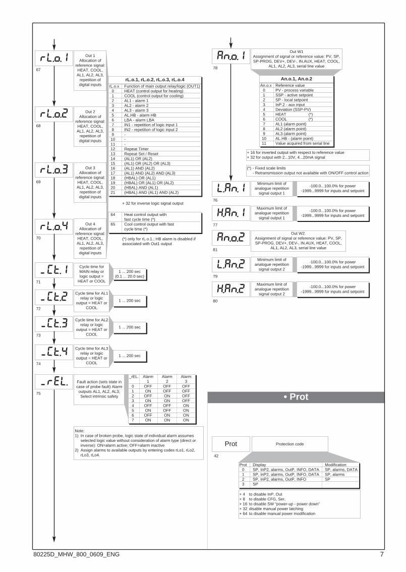
An.o.x Reference value0 PV - process variable1 SSP - active setpoint2 SP - local setpoint3 InP.2 - aux input4 Deviation (SSP-PV)5 HEAT (*)6 COOL (*)7 AL1 (alarm point)8 AL2 (alarm point)9 AL3 (alarm point)10 AL.HB - (alarm point)11 Value acquired from serial line
Out W1Assignment of signal or reference value: PV, SP,SP-PROG, DEV+, DEV-, IN.AUX, HEAT, COOL,
AL1, AL2, AL3, serial line value
Out W2.Assignment of signal or reference value: PV, SP,SP-PROG, DEV+, DEV-, IN.AUX, HEAT, COOL,
AL1, AL2, AL3, serial line value
Out 1Allocation of
reference signal:HEAT, COOL,AL1, AL2, AL3,
repetition ofdigital inputs
Cycle time for AL3relay or logic
output = HEAT orCOOL
67
68
69
70
74
75
76
77
78
79
80
81
_rEL. Alarm Alarm Alarm1 2 3
0 OFF OFF OFF1 ON OFF OFF2 OFF ON OFF3 ON ON OFF4 OFF OFF ON5 ON OFF ON6 OFF ON ON7 ON ON ON
-100.0...100.0% for power-1999...9999 for inputs and setpoint
An.o.1, An.o.2
1 ... 200 sec
+ 16 for inverted output with respect to reference value+ 32 for output with 2...10V, 4...20mA signal
(*) - Fixed scale limits- Retransmission output not available with ON/OFF control action
71
72
73
Cycle time forMAIN relay orlogic output =
HEAT or COOL
Cycle time for AL1relay or logic
output = HEAT orCOOL
Cycle time for AL2relay or logic
output = HEAT orCOOL
1 ... 200 sec(0.1 ... 20.0 sec)
1 ... 200 sec
1 ... 200 sec
Out 2Allocation of
reference signal:HEAT, COOL,AL1, AL2, AL3,
repetition ofdigital inputs
Out 3Allocation of
reference signal:HEAT, COOL,AL1, AL2, AL3,
repetition ofdigital inputs
Out 4Allocation of
reference signal:HEAT, COOL,AL1, AL2, AL3,
repetition ofdigital inputs
-100.0...100.0% for power-1999...9999 for inputs and setpoint
-100.0...100.0% for power-1999...9999 for inputs and setpoint
-100.0...100.0% for power-1999...9999 for inputs and setpoint
rL.o.1, rL.o.2, rL.o.3, rL.o.4
+ 32 for inverse logic signal output
rL.o.x Function of main output relay/logic (OUT1)0 HEAT (control output for heating)1 COOL (control output for cooling)2 AL1 - alarm 13 AL2 - alarm 24 AL3 - alarm 35 AL.HB - alarm HB6 LBA - alarm LBA7 IN1 - repetition of logic input 18 IN2 - repetition of logic input 29 -10 -11 -12 Repeat Timer13 Repeat Set / Reset14 (AL1) OR (AL2)15 (AL1) OR (AL2) OR (AL3)16 (AL1) AND (AL2)17 (AL1) AND (AL2) AND (AL3)18 (HBAL) OR (AL1)19 (HBAL) OR (AL1) OR (AL2)20 (HBAL) AND (AL1)21 (HBAL) AND (AL1) AND (AL2)
64 Heat control output withfast cycle time (*)
65 Cool control output with fastcycle time (*)
(*) only for rL.o.1.; HB alarm is disabled ifassociated with Out1 output
Prot
42
Protection code
Prot Display Modification0 SP, InP2, alarms, OutP, INFO, DATA SP, alarms, DATA1 SP, InP2, alarms, OutP, INFO, DATA SP, alarms2 SP, InP2, alarms, OutP, INFO SP3 SP
+ 4 to disable InP, Out + 8 to disable CFG, Ser, + 16 to disable SW “power-up - power down”+ 32 disable manual power latching+ 64 to disable manual power modification
-
-
-
-
-
780225D_MHW_800_0609_ENG
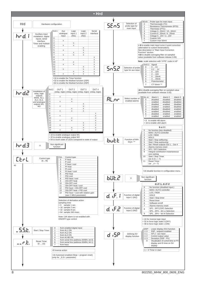
d.i.f.2
d.i.f.1
disp
(trl
s.S.t.
r.t.
sens
al.nr
butt
hrd.1
hrd.2
• Hrd
Hrd Hardware configuration
Auxiliary inputinstallation, digital
inputs, serialinterface.
Timer and multisetenabling
Installation ofrelay, logic
outputsMAIN, AL1,AL2, AL3,
and analogueoutputs W1,
W2
+ 16 to enable analogue output W1+ 32 to enable analogue output W2+ 64 to invert state of LEDs compared to state of output
+ 8 to enable HB alarm+ 16 to enable LBA alarm
d.i.F.1, d.i.F.2
Function of digitalinput 1 (IN1)
+ 16 for inverse logic input+ 32 to force logic state 0 (OFF)+ 48 to force logic state 1 (ON)
Function of digitalinput 2 (IN2)
hrd.1 Aux Logic Logic Serialanalogue input 1 input 2 interface
input (IN1) (IN2)01 x2 x3 x x4 x5 x x6 x x7 x x x8 x9 x x10 x x11 x x x12 x x13 x x x14 x x x15 x x x x
hrd.2 OUT 1 OUT 2 OUT 3 OUT 4(relay, logic) (relay, logic) (relay, logic) (relay, logic)
01 x2 x3 x x4 x5 x x6 x x7 x x x8 x9 x x10 x x11 x x x12 x x13 x x x14 x x x15 x x x x
SnS.2 Signal0 0 ... 1V1 0.2 ... 1V2 0 ... 10V3 2 ... 10V4 0 ... 20mA5 4 ... 20mA6 Potentiometer
7 CT 50mA ~
AL.nr Alarm 1 Alarm 2 Alarm 30 disabled disabled disabled1 enabled disabled disabled2 disabled enabled disabled3 enabled enabled disabled4 disabled disabled enabled5 enabled disabled enabled6 disabled enabled enabled7 enabled enabled enabled
0 No function (disabled input.)1 MAN / AUTO controller2 LOC / REM3 HOLD4 Start / Stop timer5 Reset timer6 Software on/off7 Alarms memory reset
8 SP1...SP2 (2SP) SelectionSP1...SP4 – bit Lo Selection
9 SP1...SP4 – bit Hi Selection
Selection of probetype for aux input
Select number ofenabled alarms
+16 to enable the Timer function +32 to enable the Multiset function (2SP)+64 to enable the Multiset function (4SP)
Start / Stop Timer0 from enabled digital input1 from AL1 ON2 from AL2 ON3 from AL3 ON4 from ALHB ON5 from serial line (address 0049H, bit 0)6 from serial line (address 0049H, bit 1)7 from keys
Reset Timer(0 ... 15)
+ 8 to enable main input curve 4 point correction(alternative to custom linearization).See description in “Main Input CorrectionFunction” section.+16 to disable averaging filter on sampledvalue (available from software release 3.05)
+8 to disable averaging filter on sampled value(available from software release 3.05)
SEnS Probe type for main input0 Thermocouple (TC)1 Resistance Thermometer (RTD)2 Thermistor (PTC)3 Voltage 0...50mV / 10...50mV4 Current 0...20mA / 4...20mA5 Voltage 0...10V / 2...10V6 Custom 10V7 Custom max 50mV
Selection ofprobe type for
main input
Control type[0...78]
43
CtrL Control type0 P heat1 P cool2 P heat / cool3 PI heat4 PI cool5 PI heat / cool6 PID heat7 PID cool8 PID heat / cool9 ON-OFF heat10 ON-OFF cool11 ON-OFF heat / cool12 PID heat + ON-OFF cool13 ON-OFF heat + PID cool14 PID heat + cool with relative gain
(see C.MEd parameter)
0 No function (key disabled)1 MAN / AUTO controller2 LOC / REM3 HOLD4 Start / Stop selftuning5 Start / Stop autotuning6 Set / Reset outputs Out 1... Out 47 Alarms memory reset8 SP1 / SP2 Selection9 Integral contribution instantaneous
zero setting10 Start / Stop Timer
(se S.S.t. = 7)11 Reset Timer
(se _rt = 7)
+16 Autoreset enabled (Stop = program reset)(only for _S.S.t. parameter)
+8 inverse action
+16 disable function in configuration menu
Selection of derivative actionsampling time:+ 0 sample 1 sec.+ 16 sample 2 sec.+ 32 sample 8 sec.+ 64 sample 240 msec.
b u t t
Function of M/Akeys: “*”
Defining SVdisplay function
diSP Lower display (SV) function(*) 0 SSP - setpoint enabled(*) 1 InP.2 - aux input(*) 2 Control output value(*) 3 Deviation (SSP - PV)
8 Visualisation of current time on PVdisplay and tS time on SVdisplay
(*) + 4 Timer in start
Note: scale selection with “tYPE” code in InP
Note: LbA alarm is not enabled withON/OFF type control
sns.2
-
--
hrd.3 0Non significant
function
but.2 0Non significant
function
8 80225D_MHW_800_0609_ENG
xead
pa.14
led.1
led.2
led.3
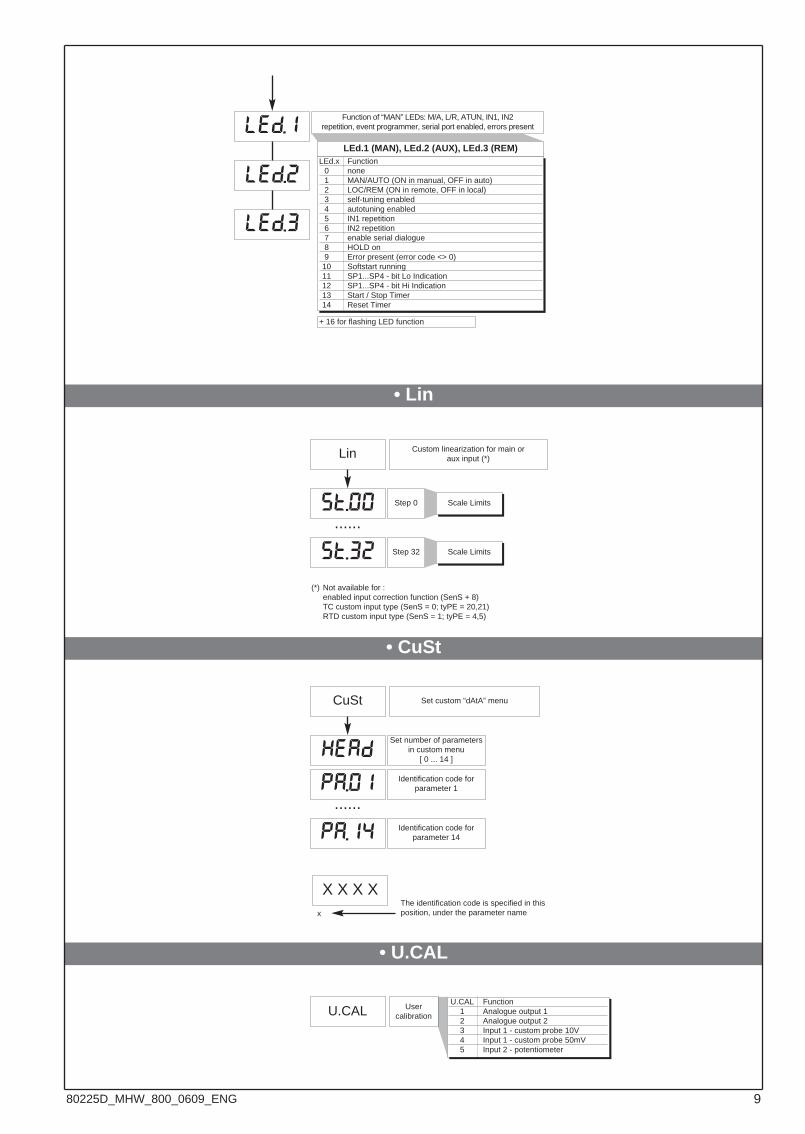
LEd.x Function0 none1 MAN/AUTO (ON in manual, OFF in auto)2 LOC/REM (ON in remote, OFF in local)3 self-tuning enabled4 autotuning enabled 5 IN1 repetition6 IN2 repetition7 enable serial dialogue8 HOLD on9 Error present (error code <> 0)10 Softstart running11 SP1...SP4 - bit Lo Indication12 SP1...SP4 - bit Hi Indication13 Start / Stop Timer14 Reset Timer
Function of “MAN” LEDs: M/A, L/R, ATUN, IN1, IN2repetition, event programmer, serial port enabled, errors present
+ 16 for flashing LED function
LEd.1 (MAN), LEd.2 (AUX), LEd.3 (REM)
• Lin
Lin Custom linearization for main oraux input (*)
Step 0
Step 32
......Scale Limits
Scale Limits
• CuSt
Set number of parametersin custom menu
[ 0 ... 14 ]
CuSt Set custom “dAtA” menu
Identification code forparameter 1
Identification code forparameter 14
......
• U.CAL
U.CAL Usercalibration
X X X Xx
The identification code is specified in thisposition, under the parameter name
(*) Not available for :enabled input correction function (SenS + 8)TC custom input type (SenS = 0; tyPE = 20,21)RTD custom input type (SenS = 1; tyPE = 4,5)
st.00
st.32
pa.01
U.CAL Function1 Analogue output 12 Analogue output 23 Input 1 - custom probe 10V4 Input 1 - custom probe 50mV5 Input 2 - potentiometer
980225D_MHW_800_0609_ENG

6 • TIMER + 2 SET POINT, TIMER FUNCTION
The timer functionality is enabled in Hrd configuration in hrd.1 parameter setting the code +16 or +48 to activate the selection of two set points. In the case of enabling, parameters _S.S.t. (start/stop timer) and _ _r.t. (reset timer) define the functioning modality.The intervention threshold of the tS timer can be set at level 1 of programming with bottom of scale 9999 sec. The enabling to the timer, as also the reset condition, can occur due to external contact or alarm conditions (AL1, AL2, AL3, ALHb).The reset function, always active on the status, zero sets the value of the timer and keeps it blocked even if the start is present. In the absence of enabling (stop) the autoreset condition can be active for which the timer zero sets at each stop. It is possible to make the timer visible on the SV display during the active counting phase as specified by the diSP parameter. On reaching the preset time (tS), it is possible to activate a relay of the four available or select set point 2.
7 • MULTISET FUNCTION, SET GRADIENT
SP1SP2
SP3
SP4
SP1(*)
ON ON
ON
SP
IN1
IN2
t
t
t
(*) in the case of set gradient
(*)
IN1
IN2
ts
Timer
0
Reset
StartStop
t
tSP1
SP2 ts
t
t
t
Timer
Reset IN1
SP2
SP1
AL1
SPSV
Abilitation from AL1 active
(*) if the autoresetfunction is enabled
the passage between SP1 and SP2 occurs on the basis of theGrSP value setpoint gradient (0=immediate passage)
The function is enabled in Hrd configuration in the parameter hrd.1 setting code +64. It allows the setting of 4 set points which can be selectedby means of combinations of digital inputs (IN1, IN2).The selection between set point 1 and set point 2 can also be carried out by means of front key. It is possible to visualise the selection between set point 1 / 2 using leds. SET GRADIENT: if set ≠ 0, when switching on and during the auto/man passage the set point is assumed to be equal to PV, with gradient set itreaches the local set or that selected. Every set variation is subject to gradient. The set gradient is inhibited on switching on when the self tuning is enabled. If the set gradient is set ≠ 0, this is active even on local setpoint variations, which can be set only in the relative SP menu. The adjustment setpoint reaches the value set with a speed defined by the gradient.
10 80225D_MHW_800_0609_ENG
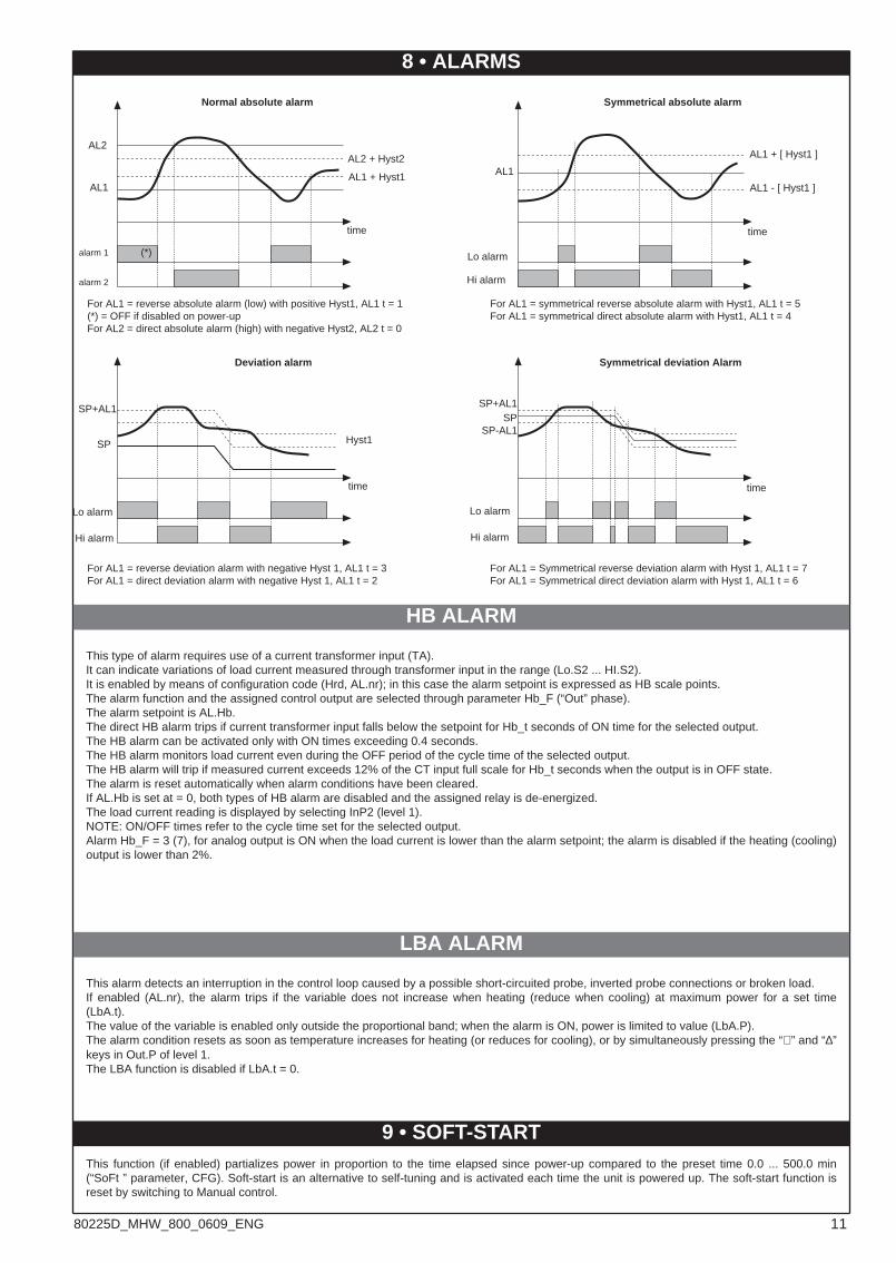
This alarm detects an interruption in the control loop caused by a possible short-circuited probe, inverted probe connections or broken load.If enabled (AL.nr), the alarm trips if the variable does not increase when heating (reduce when cooling) at maximum power for a set time(LbA.t).The value of the variable is enabled only outside the proportional band; when the alarm is ON, power is limited to value (LbA.P). The alarm condition resets as soon as temperature increases for heating (or reduces for cooling), or by simultaneously pressing the “∇ ” and “∆”keys in Out.P of level 1.The LBA function is disabled if LbA.t = 0.
LBA ALARM
This type of alarm requires use of a current transformer input (TA).It can indicate variations of load current measured through transformer input in the range (Lo.S2 ... HI.S2).It is enabled by means of configuration code (Hrd, AL.nr); in this case the alarm setpoint is expressed as HB scale points.The alarm function and the assigned control output are selected through parameter Hb_F (“Out” phase).The alarm setpoint is AL.Hb.The direct HB alarm trips if current transformer input falls below the setpoint for Hb_t seconds of ON time for the selected output.The HB alarm can be activated only with ON times exceeding 0.4 seconds.The HB alarm monitors load current even during the OFF period of the cycle time of the selected output.The HB alarm will trip if measured current exceeds 12% of the CT input full scale for Hb_t seconds when the output is in OFF state.The alarm is reset automatically when alarm conditions have been cleared.If AL.Hb is set at = 0, both types of HB alarm are disabled and the assigned relay is de-energized.The load current reading is displayed by selecting InP2 (level 1).NOTE: ON/OFF times refer to the cycle time set for the selected output.Alarm Hb_F = 3 (7), for analog output is ON when the load current is lower than the alarm setpoint; the alarm is disabled if the heating (cooling)output is lower than 2%.
HB ALARM
8 • ALARMS
time
AL1 + Hyst1
AL2 + Hyst2AL2
AL1
alarm 1
alarm 2
(*)
For AL1 = reverse absolute alarm (low) with positive Hyst1, AL1 t = 1(*) = OFF if disabled on power-upFor AL2 = direct absolute alarm (high) with negative Hyst2, AL2 t = 0
For AL1 = symmetrical reverse absolute alarm with Hyst1, AL1 t = 5For AL1 = symmetrical direct absolute alarm with Hyst1, AL1 t = 4
Normal absolute alarm Symmetrical absolute alarm
Lo alarm
Hi alarm
AL1
AL1 + [ Hyst1 ]
AL1 - [ Hyst1 ]
time
For AL1 = reverse deviation alarm with negative Hyst 1, AL1 t = 3For AL1 = direct deviation alarm with negative Hyst 1, AL1 t = 2
For AL1 = Symmetrical reverse deviation alarm with Hyst 1, AL1 t = 7For AL1 = Symmetrical direct deviation alarm with Hyst 1, AL1 t = 6
time
SP+AL1SP
Lo alarm
Hi alarm
SP+AL1
SP
Lo alarm
Hi alarm
time
Hyst1
Deviation alarm Symmetrical deviation Alarm
SP-AL1
This function (if enabled) partializes power in proportion to the time elapsed since power-up compared to the preset time 0.0 ... 500.0 min(“SoFt ” parameter, CFG). Soft-start is an alternative to self-tuning and is activated each time the unit is powered up. The soft-start function isreset by switching to Manual control.
9 • SOFT-START
1180225D_MHW_800_0609_ENG
Proportional Action:action in which contribution to output is proportional to deviation at input (deviation = difference between controlled variable and setpoint).Derivative Action:action in which contribution to output is proportional to rate of variation input deviation.Integral Action:action in which contribution to output is proportional to integral of time of input deviation.
Influence of Proportional, Derivative and Integral actions on response of process under control* An increase in P.B. reduces oscillations but increases deviation.* A reduction in P.B. reduces the deviation but provokes oscillations of the controlled variable (the system tends to be unstable if P.B. value istoo low).* An increase in Derivative Action corresponds to an increase in Derivative Time, reduces deviation and prevents oscillation up to a criticalvalue of Derivative Time, beyond which deviation increases and prolonged oscillations occur.* An increase in Integral Action corresponds to a reduction in Integral Time, and tends to eliminate deviation between the controlled variableand the setpoint when the system is running at rated speed.If the Integral Time value is too long (Weak integral action), deviation between the controlled variable and the setpoint may persist.Contact GEFRAN for more information on control actions.
10 • CONTROL ACTIONS
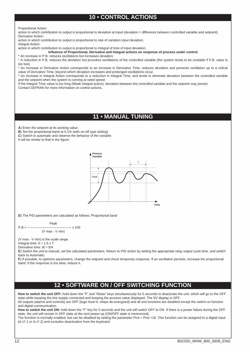
11 • MANUAL TUNING
A) Enter the setpoint at its working value.B) Set the proportional band at 0.1% (with on-off type setting).C) Switch to automatic and observe the behavior of the variable.It will be similar to that in the figure:
D) The PID parameters are calculated as follows: Proportional band
PeakP.B.= ---------------------------------------- x 100
(V max - V min)
(V max - V min) is the scale range.Integral time: It = 1.5 x TDerivative time: dt = It/4E) Switch the unit to manual, set the calculated parameters. Return to PID action by setting the appropriate relay output cycle time, and switchback to Automatic.F) If possible, to optimize parameters, change the setpoint and check temporary response. If an oscillation persists, increase the proportionalband. If the response is too slow, reduce it.
ProcessVariable
Time
T
Peak
12 • SOFTWARE ON / OFF SWITCHING FUNCTIONHow to switch the unit OFF: hold down the “F” and “Raise” keys simultaneously for 5 seconds to deactivate the unit, which will go to the OFFstate while keeping the line supply connected and keeping the process value displayed. The SV display is OFF.All outputs (alarms and controls) are OFF (logic level 0, relays de-energized) and all unit functions are disabled except the switch-on functionand digital communication.How to switch the unit ON: hold down the “F” key for 5 seconds and the unit will switch OFF to ON. If there is a power failure during the OFFstate, the unit will remain in OFF state at the next power-up (ON/OFF state is memorized).The function is normally enabled, but can be disabled by setting the parameter Prot = Prot +16. This function can be assigned to a digital input(d.i.F.1 or d.i.F.2) and excludes deactivation from the keyboard.
12 80225D_MHW_800_0609_ENG
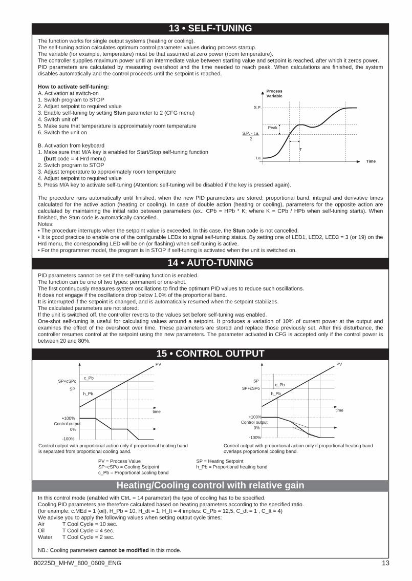
The function works for single output systems (heating or cooling).The self-tuning action calculates optimum control parameter values during process startup.The variable (for example, temperature) must be that assumed at zero power (room temperature).The controller supplies maximum power until an intermediate value between starting value and setpoint is reached, after which it zeros power.PID parameters are calculated by measuring overshoot and the time needed to reach peak. When calculations are finished, the systemdisables automatically and the control proceeds until the setpoint is reached.
How to activate self-tuning:A. Activation at switch-on1. Switch program to STOP2. Adjust setpoint to required value3. Enable self-tuning by setting Stun parameter to 2 (CFG menu)4. Switch unit off5. Make sure that temperature is approximately room temperature6. Switch the unit on
B. Activation from keyboard1. Make sure that M/A key is enabled for Start/Stop self-tuning function
(butt code = 4 Hrd menu)2. Switch program to STOP3. Adjust temperature to approximately room temperature4. Adjust setpoint to required value5. Press M/A key to activate self-tuning (Attention: self-tuning will be disabled if the key is pressed again).
The procedure runs automatically until finished, when the new PID parameters are stored: proportional band, integral and derivative timescalculated for the active action (heating or cooling). In case of double action (heating or cooling), parameters for the opposite action arecalculated by maintaining the initial ratio between parameters (ex.: CPb = HPb * K; where K = CPb / HPb when self-tuning starts). Whenfinished, the Stun code is automatically cancelled.Notes:• The procedure interrupts when the setpoint value is exceeded. In this case, the Stun code is not cancelled.• It is good practice to enable one of the configurable LEDs to signal self-tuning status. By setting one of LED1, LED2, LED3 = 3 (or 19) on theHrd menu, the corresponding LED will be on (or flashing) when self-tuning is active.• For the programmer model, the program is in STOP if self-tuning is activated when the unit is switched on.
13 • SELF-TUNING
Peak
T
S.P.
t.a.Time
ProcessVariable
S.P. - t.a.2
14 • AUTO-TUNINGPID parameters cannot be set if the self-tuning function is enabled.The function can be one of two types: permanent or one-shot.The first continuously measures system oscillations to find the optimum PID values to reduce such oscillations.It does not engage if the oscillations drop below 1.0% of the proportional band.It is interrupted if the setpoint is changed, and is automatically resumed when the setpoint stabilizes.The calculated parameters are not stored.If the unit is switched off, the controller reverts to the values set before self-tuning was enabled.One-shot self-tuning is useful for calculating values around a setpoint. It produces a variation of 10% of current power at the output andexamines the effect of the overshoot over time. These parameters are stored and replace those previously set. After this disturbance, thecontroller resumes control at the setpoint using the new parameters. The parameter activated in CFG is accepted only if the control power isbetween 20 and 80%.
time
PV
c_Pb
h_Pb
SP+cSPo
SP
+100%Control output
0%
-100%
Control output with proportional action only if proportional heating bandis separated from proportional cooling band.
Control output with proportional action only if proportional heating bandoverlaps proportional cooling band.
time
PV
c_Pb
h_PbSP+cSPo
SP
+100%Control output
0%
-100%
PV = Process Value SP = Heating SetpointSP+cSPo = Cooling Setpoint h_Pb = Proportional heating bandc_Pb = Proportional cooling band
15 • CONTROL OUTPUT
In this control mode (enabled with CtrL = 14 parameter) the type of cooling has to be specified.Cooling PID parameters are therefore calculated based on heating parameters according to the specified ratio.(for example: c.MEd = 1 (oil), H_Pb = 10, H_dt = 1, H_It = 4 implies: C_Pb = 12,5, C_dt = 1 , C_It = 4) We advise you to apply the following values when setting output cycle times:Air T Cool Cycle = 10 sec.Oil T Cool Cycle = 4 sec.Water T Cool Cycle = 2 sec.
NB.: Cooling parameters cannot be modified in this mode.
Heating/Cooling control with relative gain
1380225D_MHW_800_0609_ENG
50 / 0.05 A
152050 9640
1 2 1 2
5,5 27 5,5
920
1948
8 838
1
13
20
2
In
44 30
1010
Hole for 2.9 x 9 self-threading screws
• CURRENT TRANSFORMER17 • ACCESSORIES
These transformers are used to measure currentsof 50 ÷ 60Hz from 25A to 600A(nominal primary current). The peculiarcharacteristic of these transformers is the highnumber of secondary turns. This provides a verylow secondary current, suitable for an electronicmeasurement circuit. The secondary current maybe detected as voltage on a resistor.
CODE Ip / Is Ø Secondary n OUTPUTS Ru Vu ACCURACYWire
TA/152 025 25 / 0.05A 0.16 mm n1-2 = 500 1 - 2 40 Ω 2 Vac 2.0 %
TA/152 050 50 / 0.05A 0.18 mm n1-2 = 1000 1 - 2 80 Ω 4 Vac 1.0 %
IN = 25AacOUT = 50mAac
COD. 330200IN = 50AacOUT = 50mAac
COD. 330201
• ORDER CODE
• RS232 interface for instrument configuration
• ORDER CODE
N.B.: RS232 interface for PC configuration issupplied with configuration software.The digital communication connection must beexecuted with unit ON and inputs/outputs notconnected.
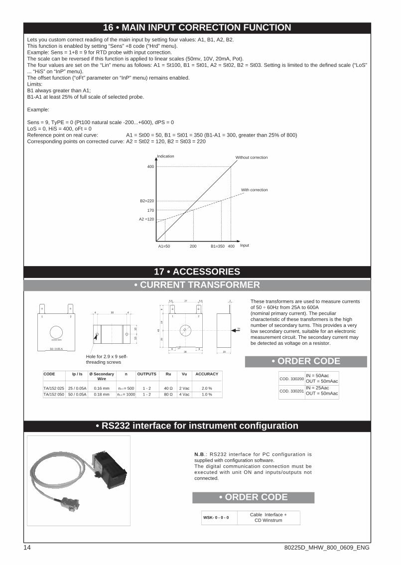
16 • MAIN INPUT CORRECTION FUNCTIONLets you custom correct reading of the main input by setting four values: A1, B1, A2, B2.This function is enabled by setting “Sens” +8 code (“Hrd” menu).Example: Sens = 1+8 = 9 for RTD probe with input correction.The scale can be reversed if this function is applied to linear scales (50mv, 10V, 20mA, Pot).The four values are set on the “Lin” menu as follows: A1 = St100, B1 = St01, A2 = St02, B2 = St03. Setting is limited to the defined scale (“LoS”... “HiS” on “InP” menu).The offset function (“oFt” parameter on “InP” menu) remains enabled.Limits:B1 always greater than A1;B1-A1 at least 25% of full scale of selected probe.
Example:
Sens = 9, TyPE = 0 (Pt100 natural scale -200...+600), dPS = 0LoS = 0, HiS = 400, oFt = 0Reference point on real curve: A1 = St00 = 50, B1 = St01 = 350 (B1-A1 = 300, greater than 25% of 800)Corresponding points on corrected curve: A2 = St02 = 120, B2 = St03 = 220
A1=50 200 B1=350 400
With correction
Without correctionIndication
Input
400
B2=220
170
A2 =120
WSK- 0 - 0 - 0Cable Interface +
CD Winstrum
14 80225D_MHW_800_0609_ENG
ORDER CODE
Read the following warnings before installing, connecting or using the device:• follow instructions precisely when connecting the device.• always use cables that are suitable for the voltage and current levels indicated in the technical specifications.• the device has no ON/OFF switch: it switches on immediately when power is turned on. For safety reasons, devices permanently connected to the powersupply require a two-phase disconnecting switch with proper marking. Such switch must be located near the device and must be easily reachable by theuser. A single switch can control several units.• if the device is connected to electrically NON-ISOLATED equipment (e.g. thermocouples), a grounding wire must be applied to assure that thisconnection is not made directly through the machine structure.• if the device is used in applications where there is risk of injury to persons and/or damage to machines or materials, it MUST be used with auxiliary alarmunits. You should be able to check the correct operation of such units during normal operation of the device. • before using the device, the user must check that all device parameters are correctly set in order to avoid injury to persons and/or damage to property.• the device must NOT be used in inflammable or explosive environments. It may be connected to units operating in such environments only by means ofsuitable interfaces in conformity to local safety regulations.• the device contains components that are sensitive to static electrical discharges. Therefore, take appropriate precautions when handling electronic circuitboards in order to prevent permanent damage to these components.Installation: installation category II, pollution level 2, double isolation• power supply lines must be separated from device input and output lines; always check that the supply voltage matches the voltage indicated on thedevice label.• install the instrumentation separately from the relays and power switching devices• do not install high-power remote switches, contactors, relays, thyristor power units (particularly if “phase angle” type), motors, etc... in the same cabinet.• avoid dust, humidity, corrosive gases and heat sources.• do not close the ventilation holes; working temperature must be in the range of 0...50°C.If the device has faston terminals, they must be protected and isolated; if the device has screw terminals, wires should be attached at least in pairs.• Power: supplied from a disconnecting switch with fuse for the device section; path of wires from switch to devices should be as straight as possible; thesame supply should not be used to power relays, contactors, solenoid valves, etc.; if the voltage waveform is strongly distorted by thyristor switching unitsor by electric motors, it is recommended that an isolation transformer be used only for the devices, connecting the screen to ground; it is important for theelectrical system to have a good ground connection; voltage between neutral and ground must not exceed 1V and resistance must be less than 6Ohm; ifthe supply voltage is highly variable, use a voltage stabilizer for the device; use line filters in the vicinity of high frequency generators or arc welders;power supply lines must be separated from device input and output lines; always check that the supply voltage matches the voltage indicated on thedevice label.• Input and output connections: external connected circuits must have double insulation; to connect analog inputs (TC, RTD) you have to: physicallyseparate input wiring from power supply wiring, from output wiring, and from power connections; use twisted and screened cables, with screen connectedto ground at only one point; to connect adjustment and alarm outputs (contactors, solenoid valves, motors, fans, etc.), install RC groups (resistor andcapacitor in series) in parallel with inductive loads that work in AC (Note: all capacitors must conform to VDE standards (class x2) and support at least 220VAC. Resistors must be at least 2W); fit a 1N4007 diode in parallel with the coil of inductive loads that operate in DC.GEFRAN spa will not be held liable for any injury to persons and/or damage to property deriving from tampering, from any incorrect orerroneous use, or from any use not conforming to the device specifications.
! WARNING: this symbol indicates danger.It is placed near the power supply circuit and near high-voltage relay contacts.
• WARNINGS
IN1 NPN; 10V/24V transmitter supply;Output 5 Analogue (W2) 0/4...20mA
07
06IN1 PNP; 10V/24V transmitter supply;Output 5 Analogue (W2) 0...10V
IN1, IN2 NPN; 10V/24V transmitter supply
V
Static D
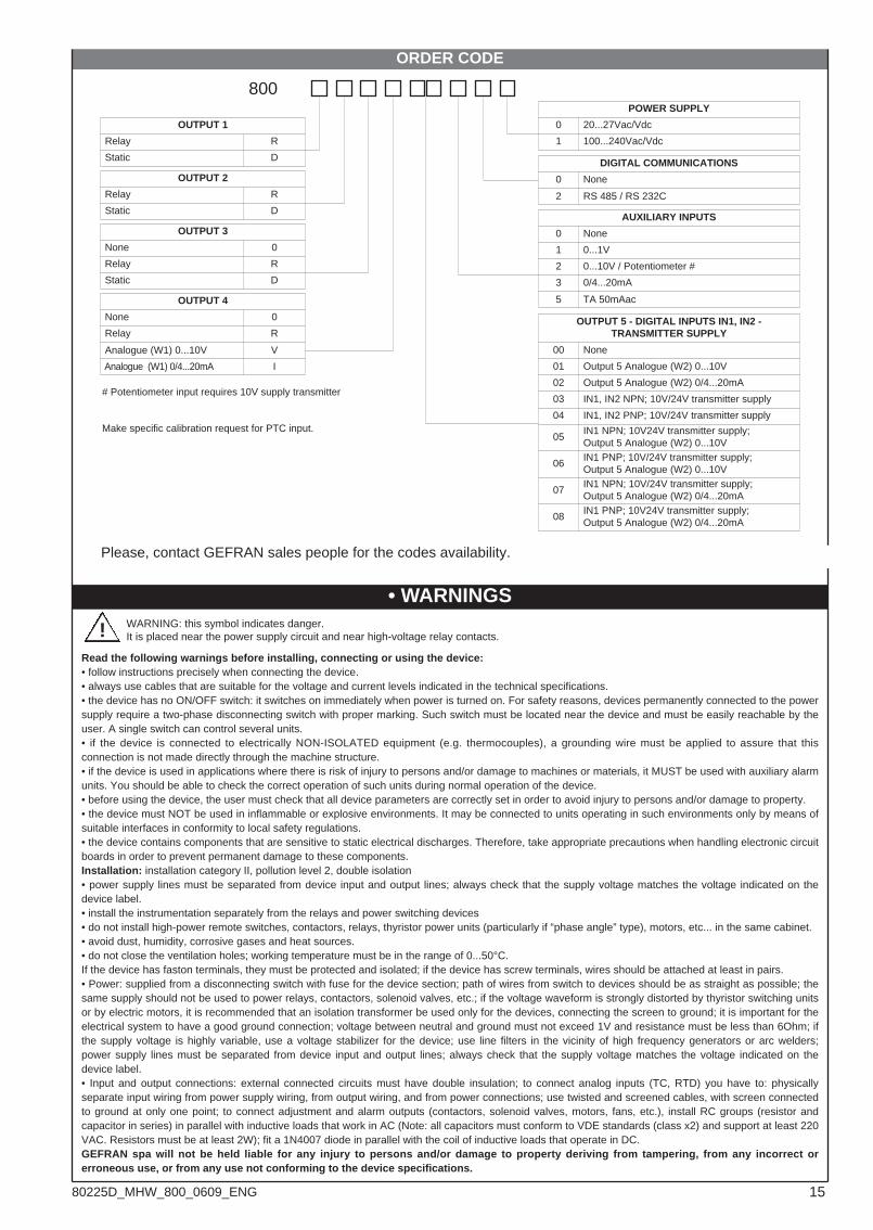
POWER SUPPLY
20...27Vac/Vdc 0
100...240Vac/Vdc1
DIGITAL COMMUNICATIONS
None0
RS 485 / RS 232C2
5 TA 50mAac
AUXILIARY INPUTS
None
0...1V
0
1
800
0...10V / Potentiometer #
0/4...20mA
2
3
OUTPUT 1
Relay
Static
R
D
OUTPUT 5 - DIGITAL INPUTS IN1, IN2 -TRANSMITTER SUPPLY
None00
Output 5 Analogue (W2) 0...10V01
Output 5 Analogue (W2) 0/4...20mA02
OUTPUT 4
None 0
Relay R
Analogue (W1) 0...10V
Analogue (W1) 0/4...20mA I
OUTPUT 2
Relay
Static
R
D
OUTPUT 3
None
Relay
0
R
03
IN1, IN2 PNP; 10V/24V transmitter supply04
IN1 NPN; 10V24V transmitter supply;Output 5 Analogue (W2) 0...10V
05
IN1 PNP; 10V24V transmitter supply;Output 5 Analogue (W2) 0/4...20mA
08
# Potentiometer input requires 10V supply transmitter
Make specific calibration request for PTC input.
Please, contact GEFRAN sales people for the codes availability.
1580225D_MHW_800_0609_ENG
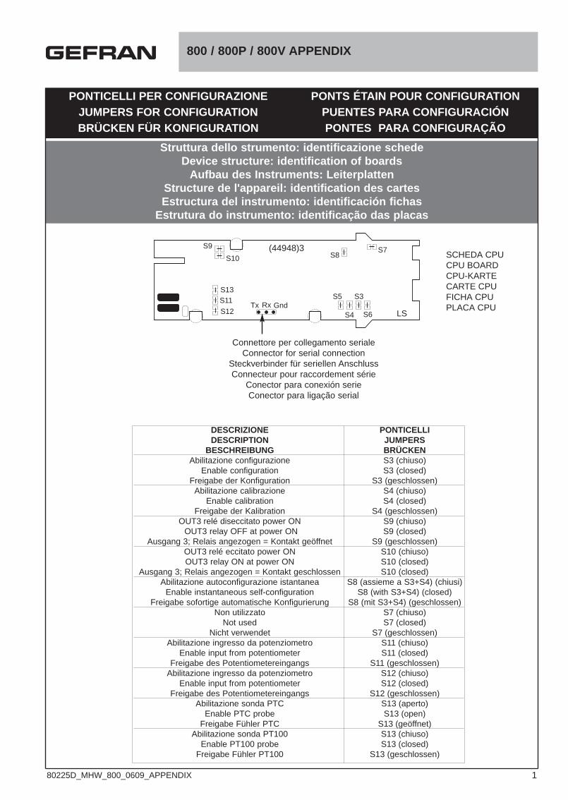
PONTICELLI PER CONFIGURAZIONEJUMPERS FOR CONFIGURATIONBRÜCKEN FÜR KONFIGURATION
PONTS ÉTAIN POUR CONFIGURATIONPUENTES PARA CONFIGURACIÓNPONTES PARA CONFIGURAÇÃO
Struttura dello strumento: identificazione schedeDevice structure: identification of boards
Aufbau des Instruments: Leiterplatten Structure de l'appareil: identification des cartesEstructura del instrumento: identificación fichas
Estrutura do instrumento: identificação das placas
800 / 800P / 800V APPENDIX
SCHEDA CPUCPU BOARDCPU-KARTECARTE CPUFICHA CPUPLACA CPU
Connettore per collegamento serialeConnector for serial connection
Steckverbinder für seriellen AnschlussConnecteur pour raccordement série
Conector para conexión serieConector para ligação serial
S10
S13
S12
S11
S9S8
S7
S5
S4 S6
S3
LSTx Rx Gnd
DESCRIZIONE PONTICELLIDESCRIPTION JUMPERS
BESCHREIBUNG BRÜCKENAbilitazione configurazione S3 (chiuso)
Enable configuration S3 (closed)Freigabe der Konfiguration S3 (geschlossen)
Abilitazione calibrazione S4 (chiuso)Enable calibration S4 (closed)
Freigabe der Kalibration S4 (geschlossen)OUT3 relé diseccitato power ON S9 (chiuso)
OUT3 relay OFF at power ON S9 (closed)Ausgang 3; Relais angezogen = Kontakt geöffnet S9 (geschlossen)
OUT3 relé eccitato power ON S10 (chiuso)OUT3 relay ON at power ON S10 (closed)
Ausgang 3; Relais angezogen = Kontakt geschlossen S10 (closed)Abilitazione autoconfigurazione istantanea S8 (assieme a S3+S4) (chiusi)
Enable instantaneous self-configuration S8 (with S3+S4) (closed)Freigabe sofortige automatische Konfigurierung S8 (mit S3+S4) (geschlossen)
Non utilizzato S7 (chiuso)Not used S7 (closed)
Nicht verwendet S7 (geschlossen)Abilitazione ingresso da potenziometro S11 (chiuso)
Enable input from potentiometer S11 (closed)Freigabe des Potentiometereingangs S11 (geschlossen)
Abilitazione ingresso da potenziometro S12 (chiuso)Enable input from potentiometer S12 (closed)
Freigabe des Potentiometereingangs S12 (geschlossen)Abilitazione sonda PTC S13 (aperto)
Enable PTC probe S13 (open)Freigabe Fühler PTC S13 (geöffnet)
Abilitazione sonda PT100 S13 (chiuso)Enable PT100 probe S13 (closed)
Freigabe Fühler PT100 S13 (geschlossen)
(44948)3
180225D_MHW_800_0609_APPENDIX
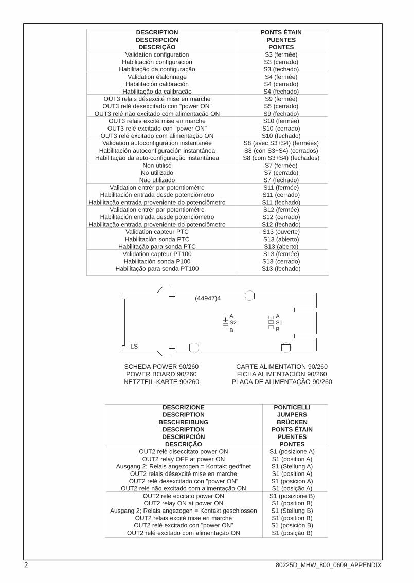
DESCRIPTION PONTS ÉTAINDESCRIPCIÓN PUENTESDESCRIÇÃO PONTES
Validation configuration S3 (fermée)Habilitación configuración S3 (cerrado)
Habilitação da configuração S3 (fechado)Validation étalonnage S4 (fermée)
Habilitación calibración S4 (cerrado)Habilitação da calibração S4 (fechado)
OUT3 relais désexcité mise en marche S9 (fermée)OUT3 relé desexcitado con "power ON" S5 (cerrado)
OUT3 relé não excitado com alimentação ON S9 (fechado)OUT3 relais excité mise en marche S10 (fermée)OUT3 relé excitado con "power ON" S10 (cerrado)
OUT3 relé excitado com alimentação ON S10 (fechado)Validation autoconfiguration instantanée S8 (avec S3+S4) (fermées)
Habilitación autoconfiguración instantánea S8 (con S3+S4) (cerrados)Habilitação da auto-configuração instantânea S8 (com S3+S4) (fechados)
Non utilisé S7 (fermée)No utilizado S7 (cerrado)Não utilizado S7 (fechado)
Validation entrér par potentiomètre S11 (fermée)Habilitación entrada desde potenciómetro S11 (cerrado)
Habilitação entrada proveniente do potenciômetro S11 (fechado)Validation entrér par potentiomètre S12 (fermée)
Habilitación entrada desde potenciómetro S12 (cerrado)Habilitação entrada proveniente do potenciômetro S12 (fechado)
Validation capteur PTC S13 (ouverte)Habilitación sonda PTC S13 (abierto)
Habilitação para sonda PTC S13 (aberto)Validation capteur PT100 S13 (fermée)Habilitación sonda P100 S13 (cerrado)
Habilitação para sonda PT100 S13 (fechado)
SCHEDA POWER 90/260POWER BOARD 90/260
NETZTEIL-KARTE 90/260
CARTE ALIMENTATION 90/260FICHA ALIMENTACIÓN 90/260
PLACA DE ALIMENTAÇÃO 90/260
DESCRIZIONE PONTICELLIDESCRIPTION JUMPERS
BESCHREIBUNG BRÜCKENDESCRIPTION PONTS ÉTAINDESCRIPCIÓN PUENTESDESCRIÇÃO PONTES
OUT2 relè diseccitato power ON S1 (posizione A)OUT2 relay OFF at power ON S1 (position A)
Ausgang 2; Relais angezogen = Kontakt geöffnet S1 (Stellung A)OUT2 relais désexcité mise en marche S1 (position A)OUT2 relé desexcitado con "power ON" S1 (posición A)
OUT2 relé não excitado com alimentação ON S1 (posição A)OUT2 relè eccitato power ON S1 (posizione B)OUT2 relay ON at power ON S1 (position B)
Ausgang 2; Relais angezogen = Kontakt geschlossen S1 (Stellung B)OUT2 relais excité mise en marche S1 (position B)OUT2 relé excitado con "power ON" S1 (posición B)
OUT2 relé excitado com alimentação ON S1 (posição B)
A
BS2
LS
A
BS1
(44947)4
2 80225D_MHW_800_0609_APPENDIX
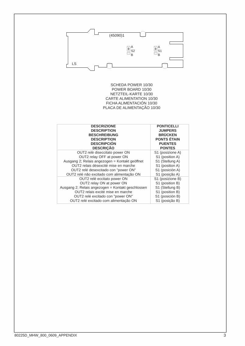
SCHEDA POWER 10/30POWER BOARD 10/30
NETZTEIL-KARTE 10/30CARTE ALIMENTATION 10/30FICHA ALIMENTACIÓN 10/30
PLACA DE ALIMENTAÇÃO 10/30
A
BS2
LS
DESCRIZIONE PONTICELLIDESCRIPTION JUMPERS
BESCHREIBUNG BRÜCKENDESCRIPTION PONTS ÉTAINDESCRIPCIÓN PUENTESDESCRIÇÃO PONTES
OUT2 relè diseccitato power ON S1 (posizione A)OUT2 relay OFF at power ON S1 (position A)
Ausgang 2; Relais angezogen = Kontakt geöffnet S1 (Stellung A)OUT2 relais désexcité mise en marche S1 (position A)OUT2 relé desexcitado con "power ON" S1 (posición A)
OUT2 relé não excitado com alimentação ON S1 (posição A)OUT2 relè eccitato power ON S1 (posizione B)OUT2 relay ON at power ON S1 (position B)
Ausgang 2; Relais angezogen = Kontakt geschlossen S1 (Stellung B)OUT2 relais excité mise en marche S1 (position B)OUT2 relé excitado con "power ON" S1 (posición B)
OUT2 relé excitado com alimentação ON S1 (posição B)
A
BS1
(45090)1
380225D_MHW_800_0609_APPENDIX
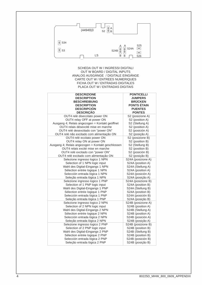
SCHEDA OUT W / INGRESSI DIGITALIOUT W BOARD / DIGITAL INPUTS
ANALOG AUSGÄNGE / DIGITALE EINGÄNGE CARTE OUT W / ENTREES NUMERIQUES
FICHA OUT W / ENTRADAS DIGITALESPLACA OUT W / ENTRADAS DIGITAIS
ABS2
LS
DESCRIZIONE PONTICELLIDESCRIPTION JUMPERS
BESCHREIBUNG BRÜCKENDESCRIPTION PONTS ÉTAINDESCRIPCIÓN PUENTESDESCRIÇÃO PONTES
OUT4 relè diseccitato power ON S2 (posizione A)OUT4 relay OFF at power ON S2 (position A)
Ausgang 4; Relais angezogen = Kontakt geöffnet S2 (Stellung A)OUT4 relais désexcité mise en marche S2 (position A)OUT4 relé desexcitado con "power ON" S2 (posición A)
OUT4 relé não excitado com alimentação ON S2 (posição A)OUT4 relè eccitato power ON S2 (posizione B)OUT4 relay ON at power ON S2 (position B)
Ausgang 4; Relais angezogen = Kontakt geschlossen S2 (Stellung B)OUT4 relais excité mise en marche S2 (position B)OUT4 relé excitado con "power ON" S2 (posición B)
OUT4 relé excitado com alimentação ON S2 (posição B)Selezione ingresso logico 1 NPN S24A (posizione A)
Selection of 1 NPN logic input S24A (position A)Wahl des Digital-Eingangs 1 NPN S24A (Stellung A)Sélection entrée logique 1 NPN S24A (position A)Selección entrada lógica 1 NPN S24A (posición A)Seleção entrada lógica 1 NPN S24A (posição A)
Selezione ingresso logico 1 PNP S24A (posizione B)Selection of 1 PNP logic input S24A (position B)
Wahl des Digital-Eingangs 1 PNP S24A (Stellung B)Sélection entrée logique 1 PNP S24A (position B)Selección entrada lógica 1 PNP S24A (posición B)Seleção entrada lógica 1 PNP S24A (posição B)
Selezione ingresso logico 2 NPN S24B (posizione A)Selection of 2 NPN logic input S24B (position A)
Wahl des Digital-Eingangs 2 NPN S24B (Stellung A)Sélection entrée logique 2 NPN S24B (position A)Selección entrada lógica 2 NPN S24B (posición A)Seleção entrada lógica 2 NPN S24B (posição A)
Selezione ingresso logico 2 PNP S24B (posizione B)Selection of 2 PNP logic input S24B (position B)
Wahl des Digital-Eingangs 2 PNP S24B (Stellung B)Sélection entrée logique 2 PNP S24B (position B)Selección entrada lógica 2 PNP S24B (posición B)Seleção entrada lógica 2 PNP S24B (posição B)
S3
A A
B B
S34S25
S26
S24BS24A
(44949)3
4 80225D_MHW_800_0609_APPENDIX
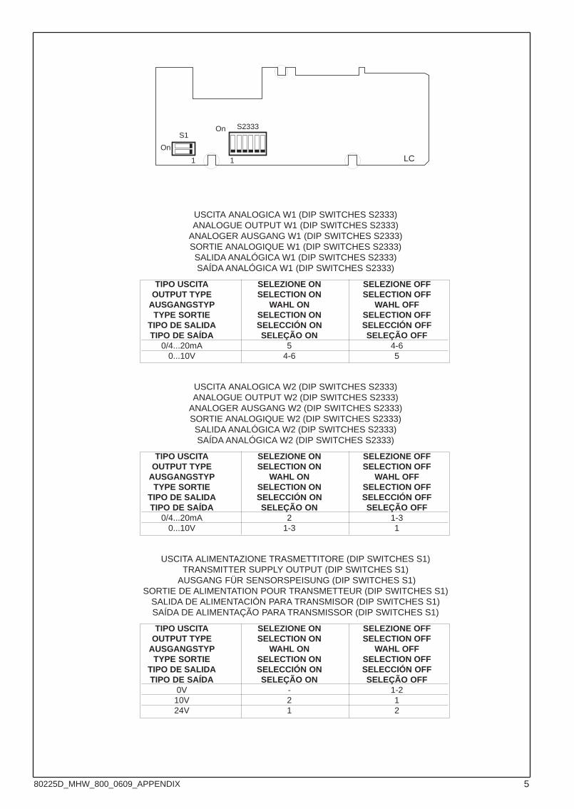
USCITA ANALOGICA W1 (DIP SWITCHES S2333)ANALOGUE OUTPUT W1 (DIP SWITCHES S2333)
ANALOGER AUSGANG W1 (DIP SWITCHES S2333)SORTIE ANALOGIQUE W1 (DIP SWITCHES S2333)SALIDA ANALÓGICA W1 (DIP SWITCHES S2333)SAÍDA ANALÓGICA W1 (DIP SWITCHES S2333)
1
S1
LC
S2333
1
On
On
TIPO USCITA SELEZIONE ON SELEZIONE OFFOUTPUT TYPE SELECTION ON SELECTION OFF
AUSGANGSTYP WAHL ON WAHL OFFTYPE SORTIE SELECTION ON SELECTION OFF
TIPO DE SALIDA SELECCIÓN ON SELECCIÓN OFFTIPO DE SAÍDA SELEÇÃO ON SELEÇÃO OFF
0/4...20mA 5 4-60...10V 4-6 5
USCITA ANALOGICA W2 (DIP SWITCHES S2333)ANALOGUE OUTPUT W2 (DIP SWITCHES S2333)
ANALOGER AUSGANG W2 (DIP SWITCHES S2333)SORTIE ANALOGIQUE W2 (DIP SWITCHES S2333)SALIDA ANALÓGICA W2 (DIP SWITCHES S2333)SAÍDA ANALÓGICA W2 (DIP SWITCHES S2333)
TIPO USCITA SELEZIONE ON SELEZIONE OFFOUTPUT TYPE SELECTION ON SELECTION OFF
AUSGANGSTYP WAHL ON WAHL OFFTYPE SORTIE SELECTION ON SELECTION OFF
TIPO DE SALIDA SELECCIÓN ON SELECCIÓN OFFTIPO DE SAÍDA SELEÇÃO ON SELEÇÃO OFF
0/4...20mA 2 1-30...10V 1-3 1
USCITA ALIMENTAZIONE TRASMETTITORE (DIP SWITCHES S1)TRANSMITTER SUPPLY OUTPUT (DIP SWITCHES S1)
AUSGANG FÜR SENSORSPEISUNG (DIP SWITCHES S1)SORTIE DE ALIMENTATION POUR TRANSMETTEUR (DIP SWITCHES S1)
SALIDA DE ALIMENTACIÓN PARA TRANSMISOR (DIP SWITCHES S1)SAÍDA DE ALIMENTAÇÃO PARA TRANSMISSOR (DIP SWITCHES S1)
TIPO USCITA SELEZIONE ON SELEZIONE OFFOUTPUT TYPE SELECTION ON SELECTION OFF
AUSGANGSTYP WAHL ON WAHL OFFTYPE SORTIE SELECTION ON SELECTION OFF
TIPO DE SALIDA SELECCIÓN ON SELECCIÓN OFFTIPO DE SAÍDA SELEÇÃO ON SELEÇÃO OFF
0V - 1-210V 2 124V 1 2
580225D_MHW_800_0609_APPENDIX
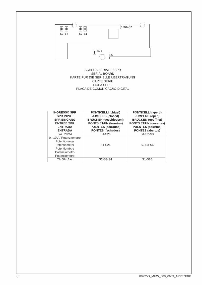
SCHEDA SERIALE / SPRSERIAL BOARD
KARTE FÜR DIE SERIELLE ÜBERTRAGUNGCARTE SÉRIEFICHA SERIE
PLACA DE COMUNICAÇÃO DIGITAL
S26
LS
S3 S4 S2 S1
INGRESSO SPR PONTICELLI (chiusi) PONTICELLI (aperti)SPR INPUT JUMPERS (closed) JUMPERS (open)
SPR EINGANG BRÜCKEN (geschlossen) BRÜCKEN (geöffnet)ENTREE SPR PONTS ÉTAIN (fermées) PONTS ÉTAIN (ouvertes)
ENTRADA PUENTES (cerrados) PUENTES (abiertos)ENTRADA PONTES (fechados) PONTES (abertos)0/4...20mA S4-S26 S1-S2-S3
0...10V / PotenziometroPotentiometerPotentiometer S1-S26 S2-S3-S4PotentiomètrePotenciómetroPotenciômetro
TA 50mAac S2-S3-S4 S1-S26
(44950)6
6 80225D_MHW_800_0609_APPENDIX