Embed Size (px)
Citation preview

Controller for control of industrial evaporatorEKC 315A
Manual
2 Manual RS8CS602 © Danfoss 02-2010 EKC 315A
Introduction
ApplicationThe controller and valve can be used where there are require-ments to accurate control of superheat and temperature in con-nection with refrigeration.E.g.:• Cold store (air coolers)• Processing plant (water chillers)• A/C plant
Advantages• The evaporator is charged optimally – even when there are great
variations of load and suction pressure• Energy savings – the adaptive regulation of the refrigerant injec-
tion ensures optimum utilisation of the evaporator and hence a high suction pressure
• Exact temperature control – the combination of adaptive evaporator and temperature control ensures great temperature accuracy for the media
• The superheating is regulated to the lowest possible value at the same time as the media temperature is controlled by the thermostat function
Functions• Regulation of superheat• Temperature control• MOP function• ON/OFF input for start/stop of regulation• Input signal that can displace the superheat reference or the
temperature reference• Alarm if the set alarm limits are exceeded• Relay output for solenoid valve• PID regulation• Output signal following the temperature showing in the display
SystemThe superheat in the evaporator is controlled by one pressure transmitter P and one temperature sensor S2.The valve can be one of the following types:• ICM• AKV (AKVA)ICM is an electronically, directly run engine valve, controlled by an ICAD type actuator. It is used with a solenoid valve in the liquid line.TQ valveThe controller can also control a TQ type valve. This valve has been discontinued from the product range, but the settings are still described in this manual.AKV is a pulsating valve.Where the AKV valve is used it also functions as solenoid valve.Temperature control is performed based on a signal from tem-perature sensor S3 which is placed in the air current before the evaporator. Temperature control is in the shape of an ON/OFF thermostat that shuts off the liquid flow in the liquid line.
Water chiller application Air cooler application
EKC 315A Manual RS8CS602 © Danfoss 02-2010 3
Operation
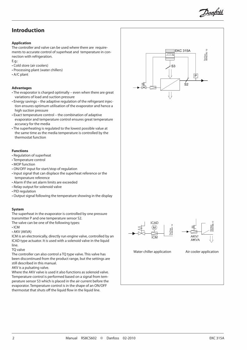
Superheat functionYou may choose between two kinds of superheat, either:• Adaptive superheat or• Load-defined superheat
MOPThe MOP function limits the valve’s opening degree as long as the evaporating pressure is higher than the set MOP value.
Override functionVia the analog input a displacement can be made of the tempera-ture reference or of the superheat reference. The signal can either be a 0-20 mA signal or a 4-20 mA signal. The reference can be displaced in positive or negative direction.
External start/stop of regulationThe controller can be started and stopped externally via a contact function connected to input terminals 1 and 2. Regulation is stopped when the connection is interrupted. The function must be used when the compressor is stopped. The controller then closes the solenoid valve so that the evaporator is not charged with refrigerant.
RelaysThe relay for the solenoid valve will operate when refrigeration is required. The relay for the alarm function works in such a way that the contact is cut-in in alarm situations and when the controller is de-energised.
Modulating/pulsating expansion valveIn 1:1 systems (one evaporator, one compressor and one condens-er) with small refrigerant charge ICM is recommended.
In a system with an AKV valve the capacity can be distributed by up to three valves if slave modules are mounted. The controller will displace the opening time of the AKV valves, so that they will not pulsate at the same time.Used as slave module is a controller of the type EKC 347.
Analog outputThe controller is provided with an analog current output which can be set to either 0-20 mA or 4-20 mA. The signal will either fol-low the superheat, opening degree of the valve or the air tem-perature.When an ICM valve is in use, the signal is used for control of the valve via the ICAD actuator.
PC operationThe controller can be provided with data communication so that it can be connected to other products in the range of ADAP-KOOL® refrigeration controls. In this way operation, monitoring and data collection can be performed from one PC – either on the spot or in a service company.
4 Manual RS8CS602 © Danfoss 02-2010 EKC 315A
Ref. Diff.
Function Para- meter
Parameter by operation via data communication
Normal display
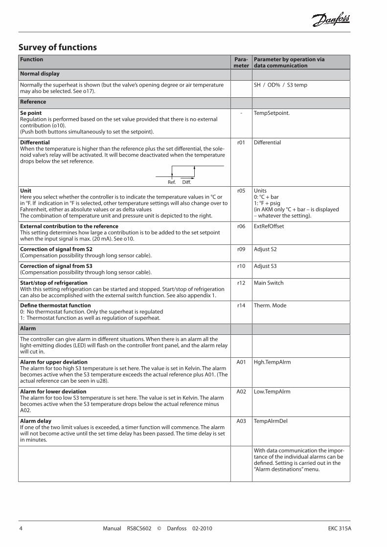
Normally the superheat is shown (but the valve’s opening degree or air temperature may also be selected. See o17).
SH / OD% / S3 temp
Reference
Se pointRegulation is performed based on the set value provided that there is no external contribution (o10).(Push both buttons simultaneously to set the setpoint).
- TempSetpoint.
DifferentialWhen the temperature is higher than the reference plus the set differential, the sole-noid valve’s relay will be activated. It will become deactivated when the temperature drops below the set reference.
r01 Differential
UnitHere you select whether the controller is to indicate the temperature values in °C or in °F. If indication in °F is selected, other temperature settings will also change over to Fahrenheit, either as absolute values or as delta valuesThe combination of temperature unit and pressure unit is depicted to the right.
r05 Units0: °C + bar1: °F + psig(in AKM only °C + bar – is displayed – whatever the setting).
External contribution to the reference This setting determines how large a contribution is to be added to the set setpoint when the input signal is max. (20 mA). See o10.
r06 ExtRefOffset
Correction of signal from S2(Compensation possibility through long sensor cable).
r09 Adjust S2
Correction of signal from S3(Compensation possibility through long sensor cable).
r10 Adjust S3
Start/stop of refrigerationWith this setting refrigeration can be started and stopped. Start/stop of refrigeration can also be accomplished with the external switch function. See also appendix 1.
r12 Main Switch
Define thermostat function0: No thermostat function. Only the superheat is regulated1: Thermostat function as well as regulation of superheat.
r14 Therm. Mode
Alarm
The controller can give alarm in different situations. When there is an alarm all the light-emitting diodes (LED) will flash on the controller front panel, and the alarm relay will cut in.
Alarm for upper deviationThe alarm for too high S3 temperature is set here. The value is set in Kelvin. The alarm becomes active when the S3 temperature exceeds the actual reference plus A01. (The actual reference can be seen in u28).
A01 Hgh.TempAlrm
Alarm for lower deviationThe alarm for too low S3 temperature is set here. The value is set in Kelvin. The alarm becomes active when the S3 temperature drops below the actual reference minus A02.
A02 Low.TempAlrm
Alarm delayIf one of the two limit values is exceeded, a timer function will commence. The alarm will not become active until the set time delay has been passed. The time delay is set in minutes.
A03 TempAlrmDel
With data communication the impor-tance of the individual alarms can be defined. Setting is carried out in the “Alarm destinations” menu.
Survey of functions
EKC 315A Manual RS8CS602 © Danfoss 02-2010 5
Control parameters
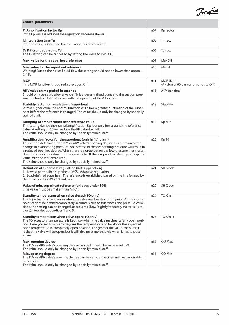
P: Amplification factor KpIf the Kp value is reduced the regulation becomes slower.
n04 Kp factor
I: Integration time TnIf the Tn value is increased the regulation becomes slower
n05 Tn sec.
D: Differentiation time TdThe D-setting can be cancelled by setting the value to min. (0).)
n06 Td sec.
Max. value for the superheat reference n09 Max SH
Min. value for the superheat referenceWarning! Due to the risk of liquid flow the setting should not be lower than approx. 2-4 K.
n10 Min SH
MOPIf no MOP function is required, select pos. Off.
n11 MOP (Bar)(A value of 60 bar corresponds to Off)
AKV valve's time period in secondsShould only be set to a lower value if it is a decentralised plant and the suction pres-sure fluctuates a lot and in line with the opening of the AKV valve.
n13 AKV per. time
Stability factor for regulation of superheatWith a higher value the control function will allow a greater fluctuation of the super-heat before the reference is changed. The value should only be changed by specially trained staff.
n18 Stability
Damping of amplification near reference valueThis setting damps the normal amplification Kp, but only just around the reference value. A setting of 0.5 will reduce the KP value by half.The value should only be changed by specially trained staff.
n19 Kp Min
Amplification factor for the superheat (only in 1:1 plant)This setting determines the ICM or AKV valve’s opening degree as a function of the change in evaporating pressure. An increase of the evaporating pressure will result in a reduced opening degree. When there is a drop-out on the low-pressure thermostat during start-up the value must be raised a bit. If there is pendling during start-up the value must be reduced a little.The value should only be changed by specially trained staff.
n20 Kp T0
Definition of superheat regulation (Ref. appendix 6)1: Lowest permissible superheat (MSS). Adaptive regulation.2: Load-defined superheat. The reference is established based on the line formed by the three points: n09, n10 and n22.
n21 SH mode
Value of min. superheat reference for loads under 10%(The value must be smaller than ”n10”).
n22 SH Close
Standby temperature when valve closed (TQ only)The TQ actuator is kept warm when the valve reaches its closing point. As the closing point cannot be defined completely accurately due to tolerances and pressure varia-tions, the setting can be changed, as required (how ”tightly”/securely the valve is to close). See also appendices 1 and 5.
n26 TQ Kmin
Standby temperature when valve open (TQ only)The TQ actuator’s temperature is kept low when the valve reaches its fully open posi-tion. Here you set how many degrees the temperature is to be above the expected open temperature in completely open position. The greater the value, the surer it is that the valve will be open, but it will also react more slowly when it has to close again.
n27 TQ Kmax
Max. opening degreeThe ICM or AKV valve’s opening degree can be limited. The value is set in %.The value should only be changed by specially trained staff.
n32 OD Max
Min. opening degreeThe ICM or AKV valve's opening degree can be set to a specified min. value, disabling full closure.The value should only be changed by specially trained staff.
n33 OD Min
6 Manual RS8CS602 © Danfoss 02-2010 EKC 315A
Miscellaneous
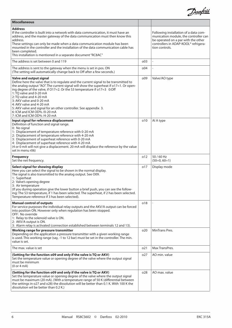
AddressIf the controller is built into a network with data communication, it must have an address, and the master gateway of the data communication must then know this address.These settings can only be made when a data communication module has been mounted in the controller and the installation of the data communication cable has been completed.This installation is mentioned in a separate document “RC8AC”
Following installation of a data com-munication module, the controller can be operated on a par with the other controllers in ADAP-KOOL® refrigera-tion controls.
The address is set between 0 and 119 o03 -
The address is sent to the gateway when the menu is set in pos. ON(The setting will automatically change back to Off after a few seconds.)
o04 -
Valve and output signalDefine here the valve that is to regulate and the current signal to be transmitted to the analog output ”AO”. The current signal will show the superheat if o17=1. Or open-ing degree of the valve, if O17=2. Or the S3 temperature if o17=3 0:Off1: TQ valve and 0-20 mA2: TQ valve and 4-20 mA3: AKV valve and 0-20 mA4: AKV valve and 4-20 mA5: AKV valve and signal for an other controller. See appendix 3.6: ICM and ICM OD% /0-20 mA7: ICM and ICM OD% /4-20 mA
o09 Valve/AO type
Input signal for reference displacementDefinition of function and signal range.0: No signal1: Displacement of temperature reference with 0-20 mA2: Displacement of temperature reference with 4-20 mA3: Displacement of superheat reference with 0-20 mA4: Displacement of superheat reference with 4-20 mA(4 or 0 mA will not give a displacement. 20 mA will displace the reference by the value set in menu r06)
o10 AI A type
FrequencySet the net frequency.
o12 50 / 60 Hz(50=0, 60=1)
Select signal for showing displayHere you can select the signal to be shown in the normal display.The signal is also transmitted to the analog output. See O09.1: Superheat2: Valve’s opening degree3: Air temperature(If you during operation give the lower button a brief push, you can see the follow-ing: The S3 temperature, if 1 has been selected. The superheat, if 2 has been selected. Temperature reference if 3 has been selected).
o17 Display mode
Manual control of outputsFor service purposes the individual relay outputs and the AKV/A output can be forced into position ON. However only when regulation has been stopped.OFF: No override1: Relay to the solenoid valve is ON.2: AKV/A output is ON.3: Alarm relay is activated (connection established between terminals 12 and 13).
o18 -
Working range for pressure transmitterDepending on the application a pressure transmitter with a given working range is used. This working range (say, -1 to 12 bar) must be set in the controller. The min. value is set.
o20 MinTrans Pres.
The max. value is set o21 Max TransPres.
(Setting for the function o09 and only if the valve is TQ or AKV)Set the temperature value or opening degree of the valve where the output signal must be minimum(0 or 4 mA)
o27 AO min. value
(Setting for the function o09 and only if the valve is TQ or AKV)Set the temperature value or opening degree of the valve where the output signal must be maximum (20 mA). (With a temperature range of 50 K (differential between the settings in o27 and o28) the dissolution will be better than 0.1 K. With 100 K the dissolution wil be better than 0.2 K.)
o28 AO max. value
EKC 315A Manual RS8CS602 © Danfoss 02-2010 7
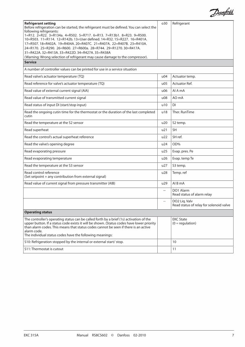
Refrigerant settingBefore refrigeration can be started, the refrigerant must be defined. You can select the following refrigerants:1=R12. 2=R22. 3=R134a. 4=R502. 5=R717. 6=R13. 7=R13b1. 8=R23. 9=R500. 10=R503. 11=R114. 12=R142b. 13=User defined. 14=R32. 15=R227. 16=R401A. 17=R507. 18=R402A. 19=R404A. 20=R407C. 21=R407A. 22=R407B. 23=R410A. 24=R170. 25=R290. 26=R600. 27=R600a. 28=R744. 29=R1270. 30=R417A. 31=R422A. 32=R413A. 33=R422D. 34=R427A. 35=R438A (Warning: Wrong selection of refrigerant may cause damage to the compressor).
o30 Refrigerant
Service
A number of controller values can be printed for use in a service situation
Read valve’s actuator temperature (TQ) u04 Actuator temp.
Read reference for valve’s actuator temperature (TQ) u05 Actuator Ref.
Read value of external current signal (AIA) u06 AI A mA
Read value of transmitted current signal u08 AO mA
Read status of input DI (start/stop input) u10 DI
Read the ongoing cutin time for the thermostat or the duration of the last completed cutin
u18 Ther. RunTime
Read the temperature at the S2 sensor u20 S2 temp.
Read superheat u21 SH
Read the control’s actual superheat reference u22 SH ref.
Read the valve’s opening degree u24 OD%
Read evaporating pressure u25 Evap. pres. Pe
Read evaporating temperature u26 Evap. temp Te
Read the temperature at the S3 sensor u27 S3 temp.
Read control reference(Set setpoint + any contribution from external signal)
u28 Temp. ref
Read value of current signal from pressure transmitter (AIB) u29 AI B mA
-- DO1 AlarmRead status of alarm relay
-- DO2 Liq. ValvRead status of relay for solenoid valve
Operating status
The controller’s operating status can be called forth by a brief (1s) activation of the upper button. If a status code exists it will be shown. (Status codes have lower priority than alarm codes. This means that status codes cannot be seen if there is an active alarm code.The individual status codes have the following meanings:
EKC State (0 = regulation)
S10: Refrigeration stopped by the internal or external start/ stop. 10
S11: Thermostat is cutout 11
8 Manual RS8CS602 © Danfoss 02-2010 EKC 315A
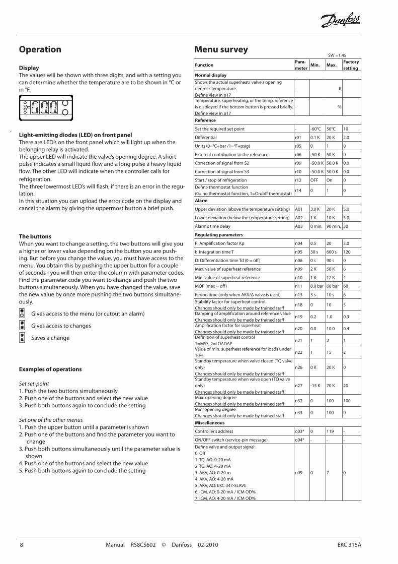
Light-emitting diodes (LED) on front panelThere are LED’s on the front panel which will light up when the belonging relay is activated.The upper LED will indicate the valve’s opening degree. A short pulse indicates a small liquid flow and a long pulse a heavy liquid flow. The other LED will indicate when the controller calls for refrigeration.The three lowermost LED’s will flash, if there is an error in the regu-lation.In this situation you can upload the error code on the display and cancel the alarm by giving the uppermost button a brief push.
DisplayThe values will be shown with three digits, and with a setting you can determine whether the temperature are to be shown in °C or in °F.
Operation Menu survey
The buttonsWhen you want to change a setting, the two buttons will give you a higher or lower value depending on the button you are push-ing. But before you change the value, you must have access to the menu. You obtain this by pushing the upper button for a couple of seconds - you will then enter the column with parameter codes. Find the parameter code you want to change and push the two buttons simultaneously. When you have changed the value, save the new value by once more pushing the two buttons simultane-ously.
Gives access to the menu (or cutout an alarm)
Gives access to changes
Saves a change
Examples of operations
Set set-point1. Push the two buttons simultaneously2. Push one of the buttons and select the new value3. Push both buttons again to conclude the setting Set one of the other menus1. Push the upper button until a parameter is shown2. Push one of the buttons and find the parameter you want to
change3. Push both buttons simultaneously until the parameter value is
shown4. Push one of the buttons and select the new value5. Push both buttons again to conclude the setting
SW =1.4x
FunctionPara-meter
Min. Max.Factory setting
Normal display
Shows the actual superheat/ valve's opening degree/ temperatureDefine view in o17
- K
Temperature, superheating, or the temp. reference is displayed if the bottom button is pressed briefly.Define view in o17
- %
Reference
Set the required set point - -60°C 50°C 10
Differential r01 0.1 K 20 K 2.0
Units (0=°C+bar /1=°F+psig) r05 0 1 0
External contribution to the reference r06 -50 K 50 K 0
Correction of signal from S2 r09 -50.0 K 50.0 K 0.0
Correction of signal from S3 r10 -50.0 K 50.0 K 0.0
Start / stop of refrigeration r12 OFF On 0
Define thermostat function(0= no thermostat function, 1=On/off thermostat)
r14 0 1 0
Alarm
Upper deviation (above the temperature setting) A01 3.0 K 20 K 5.0
Lower deviation (below the temperature setting) A02 1 K 10 K 3.0
Alarm’s time delay A03 0 min. 90 min. 30
Regulating parameters
P: Amplification factor Kp n04 0.5 20 3.0
I: Integration time T n05 30 s 600 s 120
D: Differentiation time Td (0 = off) n06 0 s 90 s 0
Max. value of superheat reference n09 2 K 50 K 6
Min. value of superheat reference n10 1 K 12 K 4
MOP (max = off) n11 0.0 bar 60 bar 60
Period time (only when AKV/A valve is used) n13 3 s 10 s 6
Stability factor for superheat control.Changes should only be made by trained staff
n18 0 10 5
Damping of amplification around reference valueChanges should only be made by trained staff
n19 0.2 1.0 0.3
Amplification factor for superheatChanges should only be made by trained staff
n20 0.0 10.0 0.4
Definition of superheat control1=MSS, 2=LOADAP
n21 1 2 1
Value of min. superheat reference for loads under 10%
n22 1 15 2
Standby temperature when valve closed (TQ valve only)Changes should only be made by trained staff
n26 0 K 20 K 0
Standby temperature when valve open (TQ valve only)Changes should only be made by trained staff
n27 -15 K 70 K 20
Max. opening degreeChanges should only be made by trained staff
n32 0 100 100
Min. opening degreeChanges should only be made by trained staff
n33 0 100 0
Miscellaneous
Controller’s address o03* 0 119 -
ON/OFF switch (service-pin message) o04* - - -
Define valve and output signal:0: Off1: TQ. AO: 0-20 mA2: TQ. AO: 4-20 mA3: AKV, AO: 0-20 m4: AKV, AO: 4-20 mA5: AKV, AO: EKC 347-SLAVE6: ICM, AO: 0-20 mA / ICM OD%7: ICM, AO: 4-20 mA / ICM OD%
o09 0 7 0
EKC 315A Manual RS8CS602 © Danfoss 02-2010 9
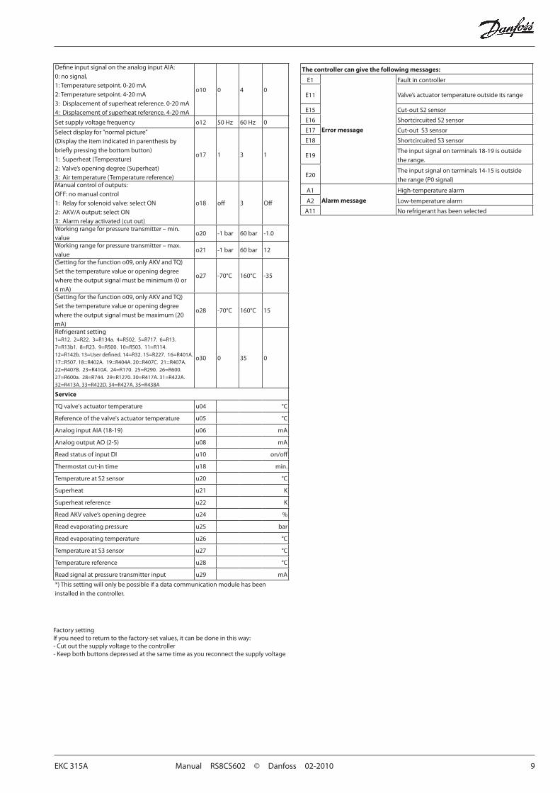
Factory settingIf you need to return to the factory-set values, it can be done in this way:- Cut out the supply voltage to the controller- Keep both buttons depressed at the same time as you recon nect the supply voltage
The controller can give the following messages:
E1
Error message
Fault in controller
E11 Valve’s actuator temperature outside its range
E15 Cut-out S2 sensor
E16 Shortcircuited S2 sensor
E17 Cut-out S3 sensor
E18 Shortcircuited S3 sensor
E19The input signal on terminals 18-19 is outside the range.
E20The input signal on terminals 14-15 is outside the range (P0 signal)
A1
Alarm message
High-temperature alarm
A2 Low-temperature alarm
A11 No refrigerant has been selected
Define input signal on the analog input AIA:0: no signal,1: Temperature setpoint. 0-20 mA2: Temperature setpoint. 4-20 mA3: Displacement of superheat reference. 0-20 mA4: Displacement of superheat reference. 4-20 mA
o10 0 4 0
Set supply voltage frequency o12 50 Hz 60 Hz 0
Select display for ”normal picture”(Display the item indicated in parenthesis by briefly pressing the bottom button) 1: Superheat (Temperature)2: Valve’s opening degree (Superheat)3: Air temperature (Temperature reference)
o17 1 3 1
Manual control of outputs:OFF: no manual control 1: Relay for solenoid valve: select ON2: AKV/A output: select ON3: Alarm relay activated (cut out)
o18 off 3 Off
Working range for pressure transmitter – min. value
o20 -1 bar 60 bar -1.0
Working range for pressure transmitter – max. value
o21 -1 bar 60 bar 12
(Setting for the function o09, only AKV and TQ)Set the temperature value or opening degree where the output signal must be minimum (0 or 4 mA)
o27 -70°C 160°C -35
(Setting for the function o09, only AKV and TQ)Set the temperature value or opening degree where the output signal must be maximum (20 mA)
o28 -70°C 160°C 15
Refrigerant setting1=R12. 2=R22. 3=R134a. 4=R502. 5=R717. 6=R13. 7=R13b1. 8=R23. 9=R500. 10=R503. 11=R114. 12=R142b. 13=User defined. 14=R32. 15=R227. 16=R401A. 17=R507. 18=R402A. 19=R404A. 20=R407C. 21=R407A. 22=R407B. 23=R410A. 24=R170. 25=R290. 26=R600. 27=R600a. 28=R744. 29=R1270. 30=R417A. 31=R422A. 32=R413A. 33=R422D. 34=R427A. 35=R438A
o30 0 35 0
Service
TQ valve's actuator temperature u04 °C
Reference of the valve's actuator temperature u05 °C
Analog input AIA (18-19) u06 mA
Analog output AO (2-5) u08 mA
Read status of input DI u10 on/off
Thermostat cut-in time u18 min.
Temperature at S2 sensor u20 °C
Superheat u21 K
Superheat reference u22 K
Read AKV valve’s opening degree u24 %
Read evaporating pressure u25 bar
Read evaporating temperature u26 °C
Temperature at S3 sensor u27 °C
Temperature reference u28 °C
Read signal at pressure transmitter input u29 mA
*) This setting will only be possible if a data communication module has been installed in the controller.
10 Manual RS8CS602 © Danfoss 02-2010 EKC 315A
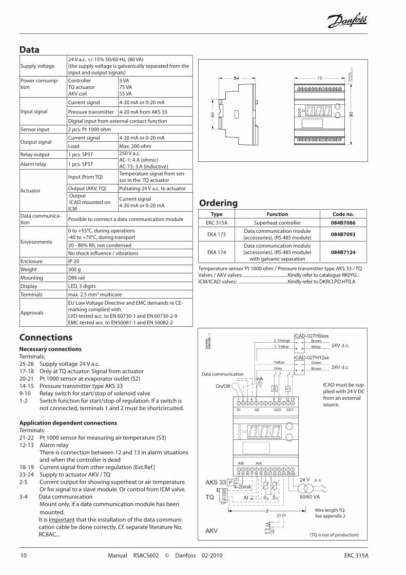
Data
Ordering
Data communication
Supply voltage24 V a.c. +/-15% 50/60 Hz, (80 VA)(the supply voltage is galvanically separated from the input and output signals)
Power consump-tion
ControllerTQ actuatorAKV coil
5 VA75 VA55 VA
Input signal
Current signal 4-20 mA or 0-20 mA
Pressure transmitter 4-20 mA from AKS 33
Digital input from external contact function
Sensor input 2 pcs. Pt 1000 ohm
Output signalCurrent signal 4-20 mA or 0-20 mA
Load Max. 200 ohm
Relay output 1 pcs. SPST 250 V a.c.AC-1: 4 A (ohmic)AC-15: 3 A (inductive)Alarm relay 1 pcs. SPST
Actuator
Input (from TQ)Temperature signal from sen-sor in the TQ actuator
Output (AKV, TQ) Pulsating 24 V a.c. to actuator Output ICAD mounted on ICM
Current signal 4-20 mA or 0-20 mA
Data communica-tion
Possible to connect a data communication module
Environments
0 to +55°C, during operations-40 to +70°C, during transport
20 - 80% Rh, not condensed
No shock influence / vibrations
Enclosure IP 20
Weight 300 g
Mounting DIN rail
Display LED, 3 digits
Terminals max. 2.5 mm2 multicore
Approvals
EU Low Voltage Directive and EMC demands re CE-marking complied with.LVD-tested acc. to EN 60730-1 and EN 60730-2-9EMC-tested acc. to EN50081-1 and EN 50082-2
Type Function Code no.
EKC 315A Superheat controller 084B7086
EKA 175Data communication module (accessories), (RS 485 module)
084B7093
EKA 174Data communication module (accessories), (RS 485 module)
with galvanic separation084B7124
Temperature sensor Pt 1000 ohm / Pressure transmitter type AKS 33 / TQ Valves / AKV valves: ............. .........................Kindly refer to catalogue RK0YG...ICM/ICAD valves: ...........................................Kindly refer to DKRCI.PD.HT0.A
Necessary connectionsTerminals:25-26 Supply voltage 24 V a.c.17-18 Only at TQ actuator: Signal from actuator20-21 Pt 1000 sensor at evaporator outlet (S2)14-15 Pressure transmitter type AKS 339-10 Relay switch for start/stop of solenoid valve1-2 Switch function for start/stop of regulation. If a switch is
not connected, terminals 1 and 2 must be shortcircuited.
Application dependent connectionsTerminals:21-22 Pt 1000 sensor for measuring air temperature (S3)12-13 Alarm relay
There is connection between 12 and 13 in alarm situa tions and when the controller is dead
18-19 Current signal from other regulation (Ext.Ref.)23-24 Supply to actuator AKV / TQ2-5 Current output for showing superheat or air temperature.
Or for signal to a slave module. Or control from ICM valve.3-4 Data communication Mount only, if a data communication module has been
mounted.It is important that the installation of the data communi-cation cable be done correctly. Cf. separate literature No. RC8AC...
Connections
Wire length TQ: See appendix 2
(TQ is out of production)
ICAD must be sup-plied with 24 V DC from an external source.
EKC 315A Manual RS8CS602 © Danfoss 02-2010 11
Installation considerationsAccidental damage, poor installation, or site conditions, can give rise to malfunctions of the control system, and ultimately lead to a plant breakdown.Every possible safeguard is incorporated into our products to prevent this. However, a wrong installation, for example, could still present problems. Electronic controls are no substitute for normal, good engineering practice.
Danfoss wil not be responsible for any goods, or plant compo-nents, damaged as a result of the above defects. It is the installer's responsibility to check the installation thoroughly, and to fit the necessary safety devices.Particular attention is drawn to the need for a “force closing” signal to controllers in the event of compressor stoppage, and to the requirement for suction line accumulators.
Your local Danfoss agent will be pleased to assist with further advice, etc.
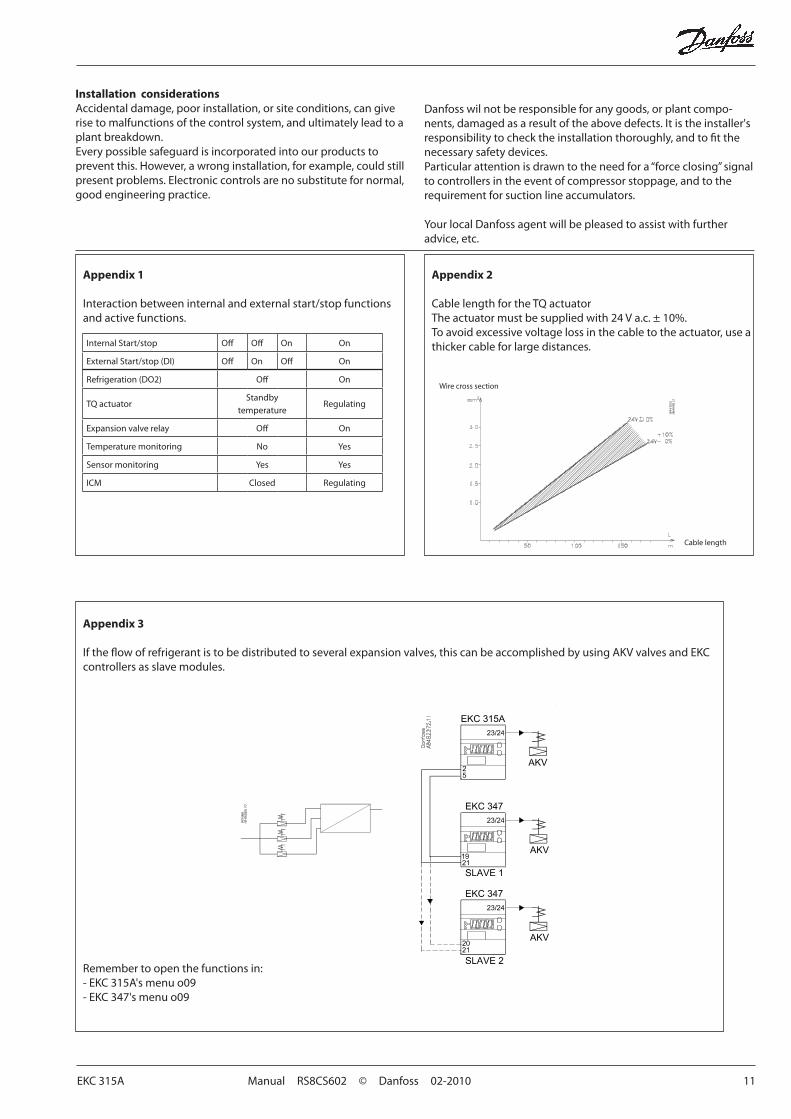
Appendix 1
Interaction between internal and external start/stop functions and active functions.
Appendix 2
Cable length for the TQ actuatorThe actuator must be supplied with 24 V a.c. ± 10%.To avoid excessive voltage loss in the cable to the actuator, use a thicker cable for large distances.
Wire cross section
Cable length
Internal Start/stop Off Off On On
External Start/stop (DI) Off On Off On
Refrigeration (DO2) Off On
TQ actuatorStandby
temperatureRegulating
Expansion valve relay Off On
Temperature monitoring No Yes
Sensor monitoring Yes Yes
ICM Closed Regulating
Appendix 3
If the flow of refrigerant is to be distributed to several expansion valves, this can be accomplished by using AKV valves and EKC controllers as slave modules.
Remember to open the functions in:- EKC 315A's menu o09- EKC 347's menu o09
12 Manual RS8CS602 © Danfoss 02-2010 EKC 315A
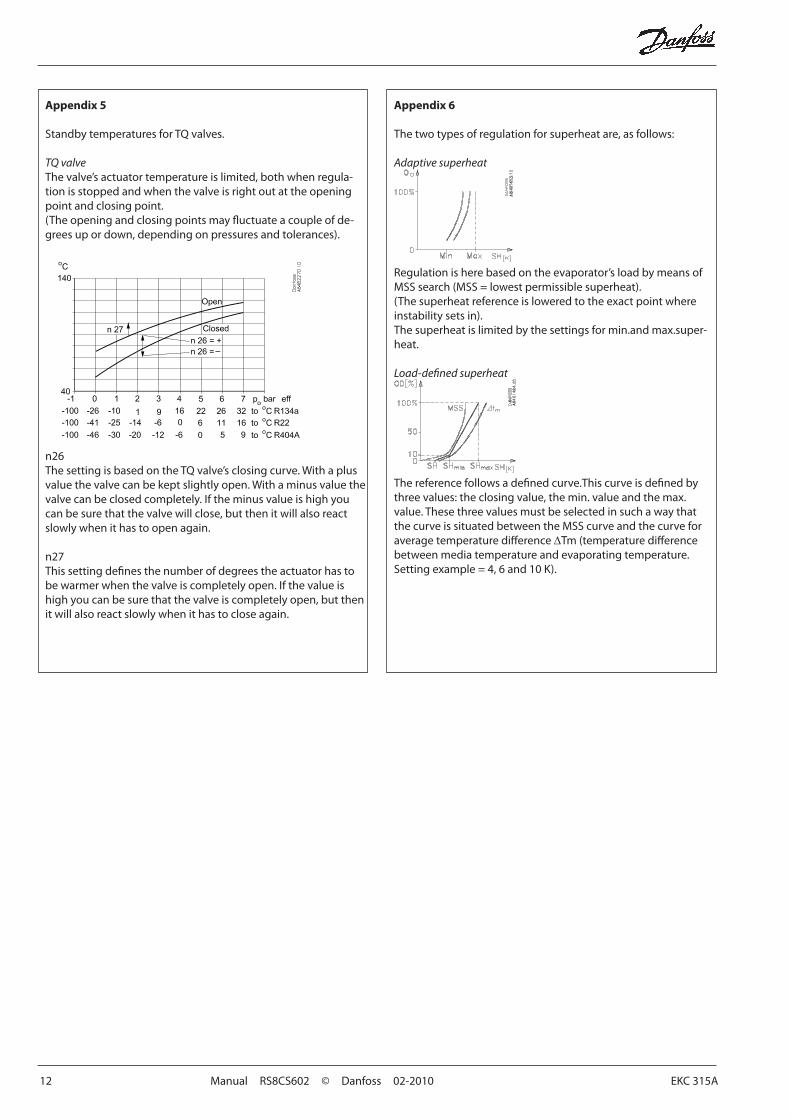
Appendix 5
Standby temperatures for TQ valves.
TQ valveThe valve’s actuator temperature is limited, both when regula-tion is stopped and when the valve is right out at the opening point and closing point.(The opening and closing points may fluctuate a couple of de-grees up or down, depending on pressures and tolerances).
n26The setting is based on the TQ valve’s closing curve. With a plus value the valve can be kept slightly open. With a minus value the valve can be closed completely. If the minus value is high you can be sure that the valve will close, but then it will also react slowly when it has to open again.
n27This setting defines the number of degrees the actuator has to be warmer when the valve is completely open. If the value is high you can be sure that the valve is completely open, but then it will also react slowly when it has to close again.
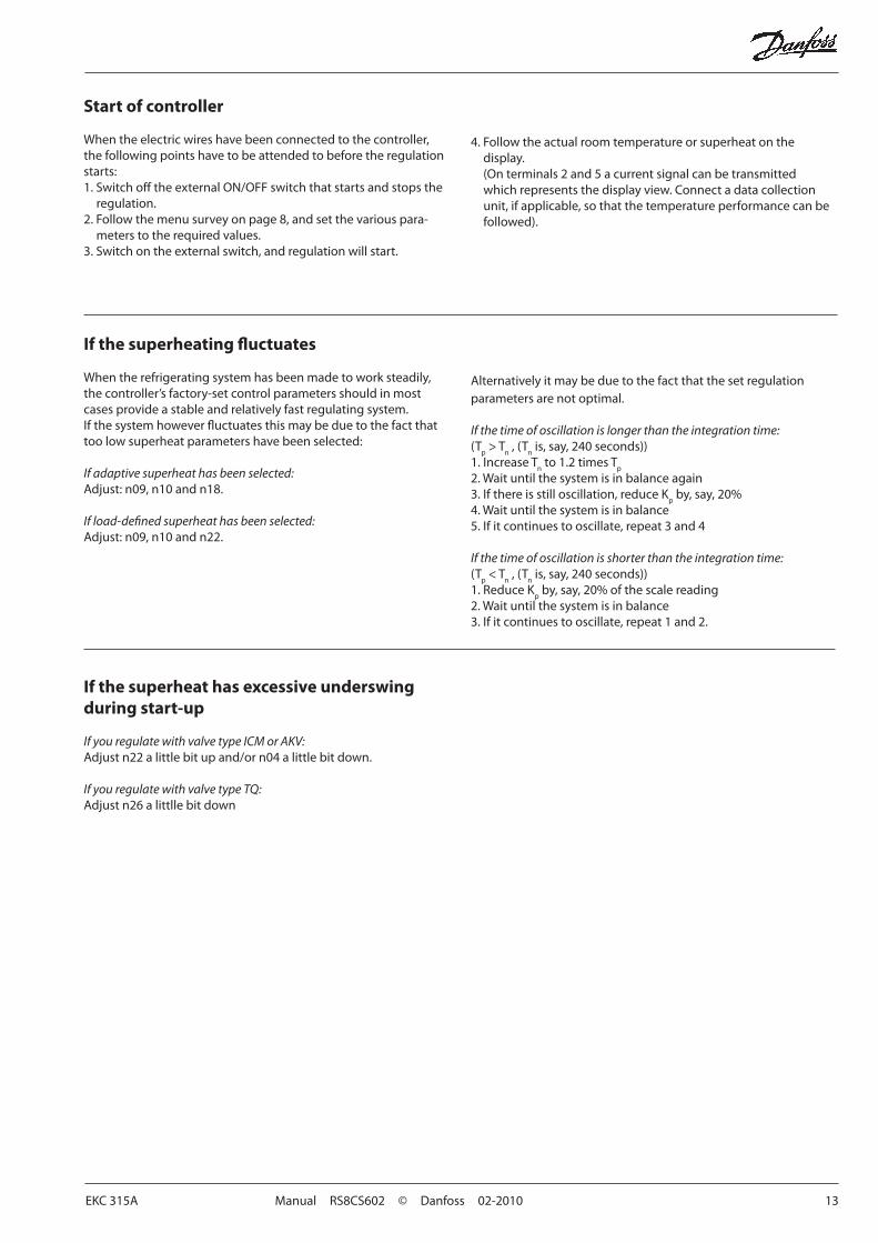
Appendix 6
The two types of regulation for superheat are, as follows:
Adaptive superheat
Regulation is here based on the evaporator’s load by means of MSS search (MSS = lowest permissible superheat).(The superheat reference is lowered to the exact point where instability sets in).The superheat is limited by the settings for min.and max.super-heat.
Load-defined superheat
The reference follows a defined curve.This curve is defined by three values: the closing value, the min. value and the max. value. These three values must be selected in such a way that the curve is situated between the MSS curve and the curve for average temperature difference ∆Tm (temperature difference between media temperature and evaporating temperature.Setting example = 4, 6 and 10 K).
EKC 315A Manual RS8CS602 © Danfoss 02-2010 13
Start of controller
When the electric wires have been connected to the controller, the following points have to be attended to before the regulation starts:1. Switch off the external ON/OFF switch that starts and stops the
regulation.2. Follow the menu survey on page 8, and set the various para- meters to the required values.3. Switch on the external switch, and regulation will start.
If the superheating fluctuates
When the refrigerating system has been made to work steadily, the controller’s factory-set control parameters should in most cases provide a stable and relatively fast regulating system.If the system however fluctuates this may be due to the fact that too low superheat parameters have been selected:
If adaptive superheat has been selected:Adjust: n09, n10 and n18.
If load-defined superheat has been selected:Adjust: n09, n10 and n22.
Alternatively it may be due to the fact that the set regulation parameters are not optimal.
If the time of oscillation is longer than the integration time:(T
p > T
n , (T
n is, say, 240 seconds))
1. Increase Tn to 1.2 times T
p
2. Wait until the system is in balance again3. If there is still oscillation, reduce K
p by, say, 20%
4. Wait until the system is in balance5. If it continues to oscillate, repeat 3 and 4
If the time of oscillation is shorter than the integration time:(T
p < T
n , (T
n is, say, 240 seconds))
1. Reduce Kp by, say, 20% of the scale reading
2. Wait until the system is in balance3. If it continues to oscillate, repeat 1 and 2.
4. Follow the actual room temperature or superheat on the display. (On terminals 2 and 5 a current signal can be transmitted which represents the display view. Connect a data collection unit, if applicable, so that the temperature performance can be followed).
If the superheat has excessive underswing during start-up
If you regulate with valve type ICM or AKV:Adjust n22 a little bit up and/or n04 a little bit down.
If you regulate with valve type TQ:Adjust n26 a littlle bit down

14 Manual RS8CS602 © Danfoss 02-2010 EKC 315A

EKC 315A Manual RS8CS602 © Danfoss 02-2010 15
16 Manual RS8CS602 © Danfoss 02-2010 EKC 315A
FC-S
PMC
List of literature
Instructions RI8GT (extract from this manual). Here you can see how controllers are mounted and programmed.
Installation guide for extended operation RC8AC Here you can see how a data communication connection to ADAP-KOOL® Refrigeration control systems can be estab-
lished.
Danfoss can accept no responsibility for possible errors in catalogues, brochures and other printed material. Danfoss reserves the right to alter its products without notice. This also applies to products already on order provided that such alternations can be made without subsequential changes being necessary in specifications already agreed.All trademarks in this material are property of the respecitve companies. Danfoss and Danfoss logotype are trademarks of Danfoss A/S. All rights reserved.