Embed Size (px)
Citation preview
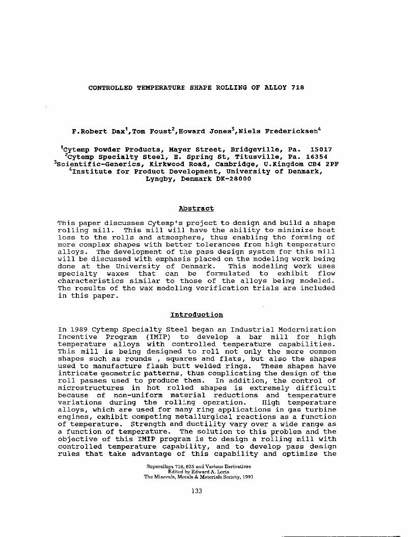
CONTROLLED TEMPERATURE SIXAPE ROLLING OF ALLOY 718
F.Robert Dax',Tom Foust',Howard Jones3,Niels Fredericksen
'Cytemp Powder Products, Mayer Street, Bridgeville, Pa. 15017 'Cytemp Specialty Steel, E. Spring St, Titusville, Pa. 16354
3Scientific-Generics, Kirkwood Road, Cambridge, U.Kingdom CB4 2PF 41nstitute for Product Development, University of Denmark,
LyngW I Denmark DK-28000
Abstract
This paper discusses Cytemp's project to design and build a shape rolling mill. This mill will have the ability to minimize heat loss to the rolls and atmosphere, thus enabling the forming of more complex shapes with better tolerances from high temperature alloys. The development of the pass design system for this mill will be discussed with emphasis placed on the modeling work being done at the University of Denmark. This modeling work uses specialty waxes that can be formulated to exhibit flow characteristics similar to those of the alloys being modeled. The results of the wax modeling verification trials are included in this paper.
Introduction
In 1989 Cytemp Specialty Steel began an Industrial Modernization Incentive Program (IMIP) to develop a bar mill for high temperature alloys with controlled temperature capabilities. This mill is being designed to roll not only the more common shapes such as rounds , squares and flats, but also the shapes used to manufacture flash butt welded rings. These shapes have intricate geometric patterns, thus complicating the design of the roll passes used to produce them. In addition, the control of microstructures in hot rolled shapes is extremely difficult because of non-uniform material reductions and temperature variations during the rolling operation. High temperature alloys, which are used for many ring applications in gas turbine engines, exhibit competing metallurgical reactions as a function of temperature. Strength and ductility vary over a wide range as a function of temperature. The solution to this problem and the objective of this IMIP program is to design a rolling mill with controlled temperature capability, and to develop pass design rules that take advantage of this capability and optimize the
Superalloys 718,625 and Various Derivatives Edited by Edward A. Lmia
The Minerals, Metals & Materials Society, 1991
133
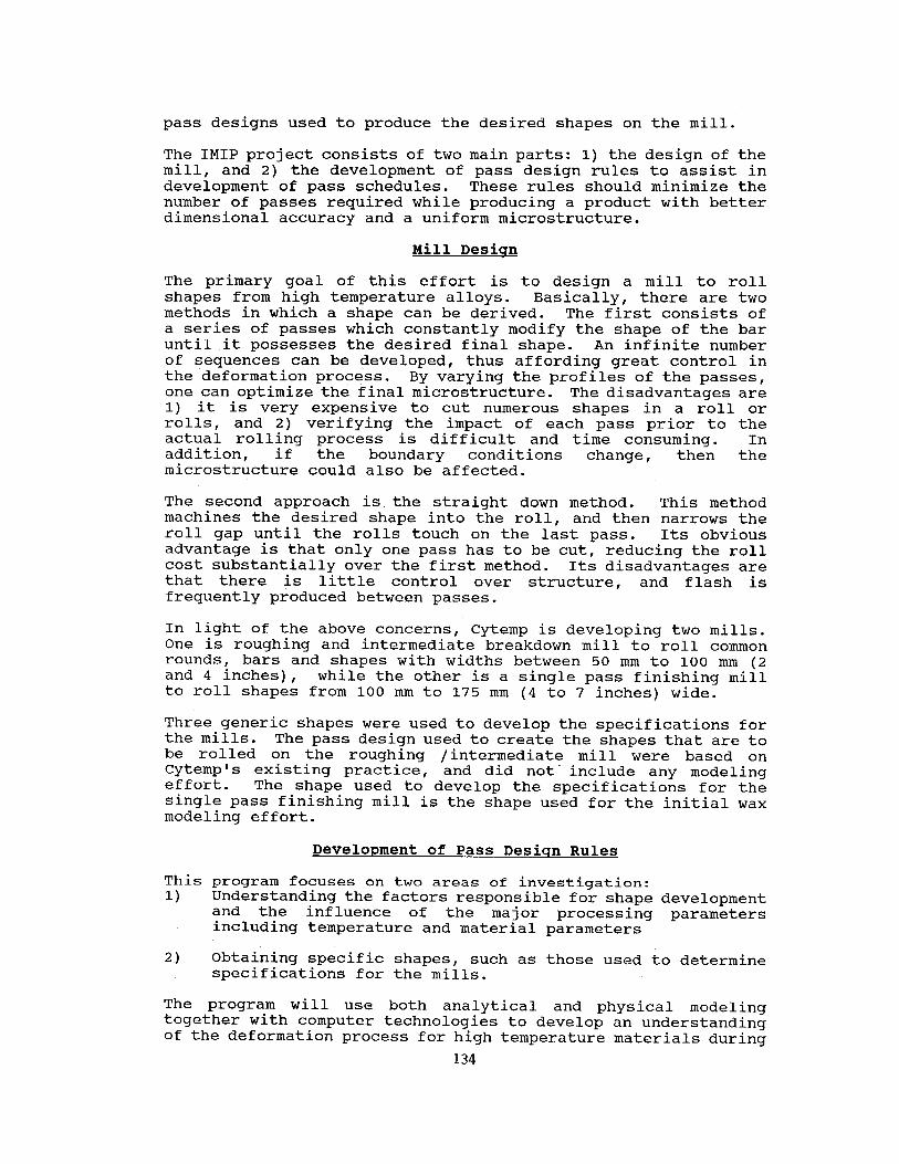
pass designs used to produce the desired shapes on the mill.
The IMIP project consists of two main parts: 1) the design of the mill, and 2) the development of pass design rules to assist in development of pass schedules. These rules should minimize the number of passes required while producing a product with better dimensional accuracy and a uniform microstructure.
Mill Desicrn
The primary goal of this effort is to design a mill to roll shapes from high temperature alloys. Basically, there are two methods in which a shape can be derived. The first consists of a series of passes which constantly modify the shape of the bar until it possesses the desired final shape. An infinite number of sequences can be developed, thus affording great control in the deformation process. By varying the profiles of the passes, one can optimize the final microstructure. The disadvantages are 1) it is very expensive to cut numerous shapes in a roll or rolls, and 2) verifying the impact of each pass prior to the actual rolling process is difficult and time consuming. In addition, if the boundary conditions change, then the microstructure could also be affected.
The second approach is the straight down method. This method machines the desired shape into the roll, and then narrows the roll gap until the rolls touch on the last pass. Its obvious advantage is that only one pass has to be cut, reducing the roll cost substantially over the first method. Its disadvantages are that there is little control over structure, and flash is frequently produced between passes.
In light of the above concerns, Cytemp is developing two mills. One is roughing and intermediate breakdown mill to roll common rounds, bars and shapes with widths between 50 mm to 100 mm (2 and 4 inches), while the other is a single pass finishing mill to roll shapes from 100 mm to 175 mm (4 to 7 inches) wide.
Three generic shapes were used to develop the specifications for the mills. The pass design used to create the shapes that are to be rolled on the roughing /intermediate mill were based on Cytemp's existing practice, effort.
and did not. include any modeling The shape used to develop the specifications for the
single pass finishing mill is the shape used for the initial wax modeling effort.
Development of Pass Desiqn Rules
This program focuses on two areas of investigation: 1) Understanding the factors responsible for shape development
and the influence of the major processing parameters including temperature and material parameters
2) Obtaining specific shapes, such as those used to determine specifications for the mills.
The program will use both analytical and physical modeling together with computer technologies to develop an understanding of the deformation process for high temperature materials during
134
rolling in both hot and isothermal conditions. The goal of the development effort is to produce an analytical and physical aid for the rolling mill pass designer. This aid will assist him in designing the rolls and the pass sequences that will minimize the number of passes while maintaining the ductility limits needed to prevent the formation of defects in the material. This will eliminate dependence on the use of trial and error. It is important to recognize that the controlled temperature capability of the new mill will enable rolling at higher reductions as well as more complex shapes and hence be outside current Cytemp pass design experience. Therefore, completely new pass design concepts will need to be developed as the current practices extrapolated.
Two modeling methods, finite element analysis, and physical methods (waxes) are required to understand the shape rolling process. It is important to note that the mechanism of shape development in rolling is not a plane strain phenomenon and that the third dimension in the ro:Lling direction is very important. For instance, it has been shown that the choice of the sequence of bites - whether one large bite or a series of small bites - can change the height of a formed fin at least twofold.
The first part of the modeling program was to demonstrate that physical modeling, using wax as the model material, can be used to develop roll geometries and preform shapes. In order to perform the rolling experiments, Cytemp used the Institute for Product Development at the Technical University of Denmark (IPU) in Lyngby, Denmark. Dr. Niels Frederiksen carried out these initial tests.
Physical Modelinq
In modeling the process it is important to develop a total understanding of the process using a combination of physical modeling and Finite Element Modeling (FEM). Although Large deformation FEM packages have been used very successfully for 2D and axisymmetric processing such as disc forging, most analytical modeling work has been done on processes less complicated than shape rolling.
There are a number of reasons why FEM alone is not the most efficient option for roll pass design.
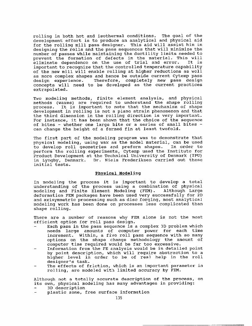
Each pass in the pass sequence is a complex 3D problem which needs large amounts of computer power for each time increment. Within, a five roll pass sequence with so many options on the shape change methodology the amount of computer time required would be far too excessive. Information from the FE analysis would be in detailed point by point description, which will require abstraction to a higher level in order to be of real help in the roll designer's task. The effects of friction, which is an important parameter in rolling, are modeled with limited accuracy by FEM.
Although not a totally accurate description of the process, on its own, physical modeling has many advantages in providing:
3D description plastic zone, free surface information
135
easy interpretation of results visual interaction with roll pass designers prediction of defect formation (in some cases) prediction of trends identification of geometry for more powerful techniques such as 3D FEM.
For instance, within the physical modeling it may be possible to identify 2D analysis which could be tackled by FEM with consequent saving in computer power and easier interpretation.
Simulation of metal flow in bulk deformation processes with non- metallic model materials such as plasticine, paraffin wax, and polymers has been developing at an increasing speed. The advantages in using such simulative materials are closely related to the fact that the yield stress is around 1000 times lower than the yield stress of metals. Whereas plasticine and lead have been used in the past, the best available materials are the new generation of waxes developed by the Scandinavian countries and being used by Professor Vanheim at the Technical University of Denmark and at the University of Valenciennes for rolling processes. These waxes can model strain hardening, an attribute not reproduced by plasticene or lead.
Advantages of physical modeling using model materials are:
1 Inexpensive tool materials such as wood, araldite, paraffin, plexiglass, etc. can be used for dies and rolls;
2 It is possible to design simple and inexpensive mills and thereby carry out experimental work without disturbing the ongoing production;
3 It is often possible to observe the l'livel' deformation in the interior of the specimen through a glass plate;
4 It is possible to consider particular details of the deformation process at a physically enlarged scale, as a special investigation;
5 The time interval between the germination of an idea and the carrying out of an experiment can be very short.
This technique is a useful tool in setting the initial roll geometry, the preform geometry and the general variables connected with metal forming in several steps, and it has been shown that material and energy can be saved and that tool life can be increased due to more rational metal flow if model- material simulations are used as guidelines for the setting of tool and process variables. The technique has also proven itself useful as an analytical tool, for example enabling the origin of flow defects such as folds, etc., to be identified.
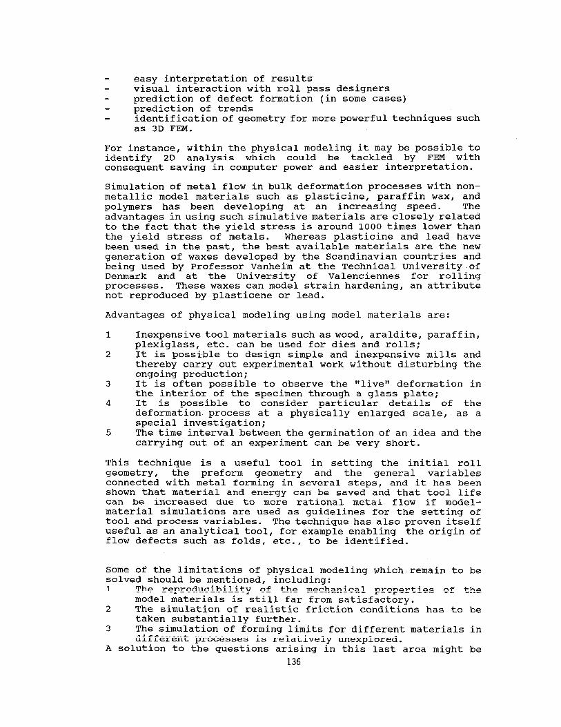
Some of the limitations of physical modeling which remain to be solved should be mentioned, including: 1 The reproducibility of the mechanical properties of the
model materials is still far from satisfactory. 2 The simulation of realistic friction conditions has to be
taken substantially further. 3 The simulation of forming limits for different materials in
different processes is relatively unexplored. A solution to the questions arising in this last area might be
136
found in a combination of computer techniques with physical simulation.
With physical modeling, information can be gained on sideways spread, tool contact lengths, extent of plastic zone, strain and work input, and loads. The main purpose of the physical modeling system in this program is to: 1 Provide information on the level of temperature uniformity
required to achieve greater shape. 2 Provide a specification for the roll geometry and material,
that is temperature capability, strength, etc. 3 Aid in the development of new pass design concepts. 4 Provide information on the free surface geometry for Finite
Element Modelling.
Construction of Roll Secrments
In order to perform the rolling experiments, an existing model material rolling set-up was used. This set-up is constructed with transparent cylindrical rolls. It was originally used for analyzing plate rolling, and allows observation of the surface deformations during rolling. The two transparent rolls are made of plexiglass with an outer diameter of 600 mm (23.6 inch). The rolls are both driven through a worm gear to insure a synchronous drive.
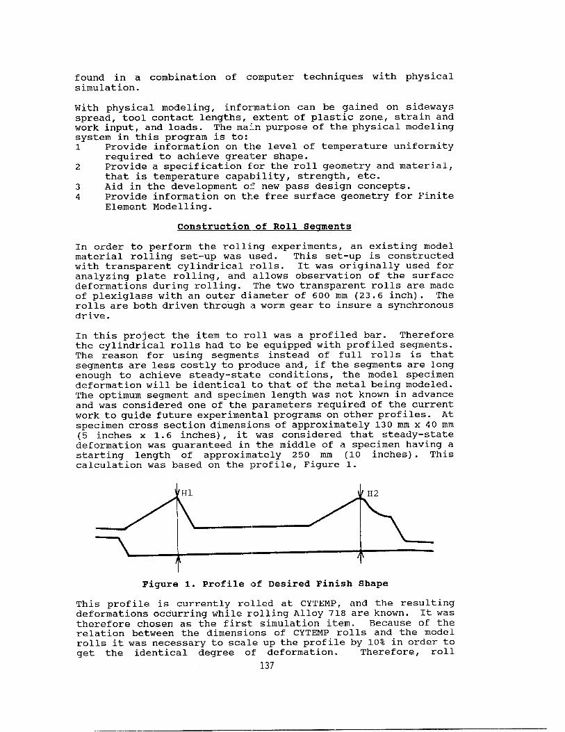
In this project the item to roll was a profiled bar. Therefore the cylindrical rolls had to be equipped with profiled segments. The reason for using segments instead of full rolls is that segments are less costly to produce and, if the segments are long enough to achieve steady-state conditions, the model specimen deformation will be identical to that of the metal being modeled. The optimum segment and specimen length was not known in advance and was considered one of the parameters required of the current work to guide future experimental programs on other profiles. At specimen cross section dimensions of approximately 130 mm x 40 mm (5 inches x 1.6 inches), it was considered that steady-state deformation was guaranteed in the middle of a specimen having a starting length of approximately 250 mm (10 inches). This calculation was based on the profile, Figure 1.
Figure 1. Profile of Desired Finish Shape
This profile is currently ro:Lled at CYTEMP, and the resulting deformations occurring while rolling Alloy 718 are known. It was therefore chosen as the first simulation item. Because of the relation between the dimensions of CYTEMP rolls and the model rolls it was necessary to scale up the profile by 10% in order to get the identical degree of deformation. Therefore, roll
137
geometry had to be scaled up by lo%, as did the starting specimen dimensions and the roll gap settings.
With a starting stock length of approximately 250 mm (10 inches) the finishing specimen length was estimated to be 600 mm (24 inches), which corresponds to a quarter of the roll circumference. It was then decided to use quarter segment rolls (90 degrees) attached to the original cylindrical rolls. The roll segments were produced from plexiglass.
Production of Model Specimens
The model specimens were produced in three versions: Homogeneous, one color material Homogeneous, one color material with surface grid Layered, two color material
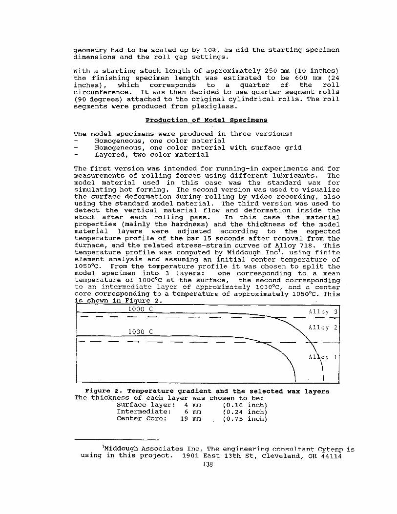
The first version was intended for running-in experiments and for measurements of rolling forces using different lubricants. The model material used in this case was the standard wax for simulating hot forming. The second version was used to visualize the surface deformation during rolling by video recording, also using the standard model material. The third version was used to detect the vertical material flow and deformation inside the stock after each rolling pass. In this case the material properties (mainly the hardness) and the thickness of the model material layers were ad justed according to the expected temperature profile of the bar 15 seconds after removal from the furnace, and the related stress-strain curves of Alloy 718. This temperature profile was computed by Middough Inc'. using finite element analysis and assuming an initial center temperature of 1050°c. From the temperature profile it was chosen to split the model specimen into 3 layers: one corresponding to a mean temperature of 1000°C at the surface, the second corresponding to an intermediate layer of approximately 1030°C, and a center core corresponding to a temperature of approximately 105O'C. This
Figure 2. Temperature gradient and the selected wax layers The thickness of each layer was chosen to be:
Surface layer: 4 mm (0.16 inch) Intermediate: 6 mm (0.24 inch) Center Core: 19 mm (0.75 inch)
'Middough Associates Inc, using in this project.
The engineering consultant Cytemp is 1901 East 13th St, Cleveland, OH 44114
138
Thus, the specimen consisted of a center core, two intermediate layers and two surface layers, with a total thickness of 39 mm (1.55 inches).
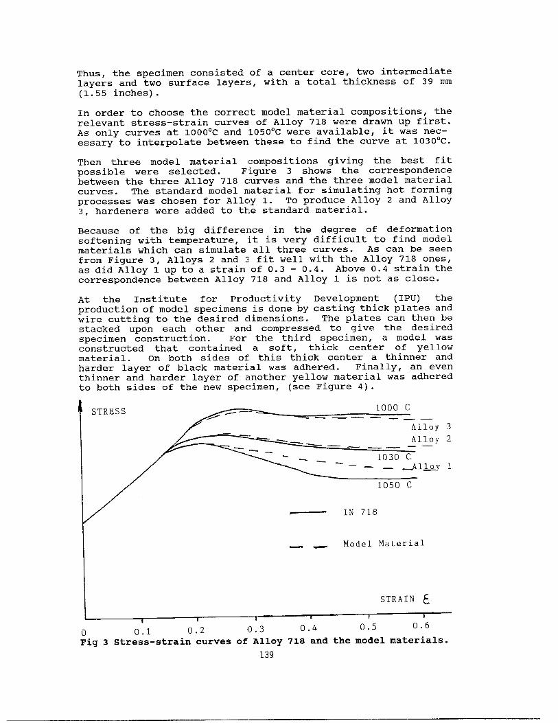
In order to choose the correct model material compositions, the relevant stress-strain curves of Alloy 718 were drawn up first. As only curves at 1000°C and 105O'C were available, it was nec- essary to interpolate between these to find the curve at 1030°C.
Then three model material compositions giving the best fit possible were selected. Figure 3 shows the correspondence between the three Alloy 718 curves and the three model material curves. The standard model material for simulating hot forming processes was chosen for Alloy 1. To produce Alloy 2 and Alloy 3, hardeners were added to the standard material.
Because of the big difference in the degree of deformation softening with temperature, it is very difficult to find model materials which can simulate all three curves. As can be seen from Figure 3, Alloys 2 and 3 fit well with the Alloy 718 ones, as did Alloy 1 up to a strain of 0.3 - 0.4. Above 0.4 strain the correspondence between Alloy 718 and Alloy 1 is not as close.
At the Institute for Productivity Development (IPU) the production of model specimens is done by casting thick plates and wire cutting to the desired dimensions. The plates can then be stacked upon each other and compressed to give the desired specimen construction. For the third specimen, a model was constructed that contained a soft, thick center of yellow material. On both sides of this thick center a thinner and harder layer of black material was adhered. Finally, an even thinner and harder layer of another yellow material was adhered to both sides of the new specimen, (see Figure 4).
STRESS 1000 c ----- ---
Alloy 3 Allr- 7
L-7 Model Material
STRAIN E
I I i I I 1
0 0.1 0.2 0 . 3 0.4 0.5 0.6 Fig 3 Stress-strain curves of Alloy 718 and the model materials.
139
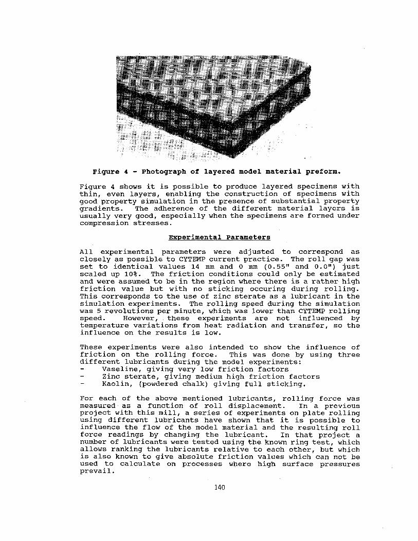
Figure 4 - Photograph of layered model material preform.
Figure 4 shows it is possible to produce layered specimens with thin, even layers, enabling the construction of specimens with good property simulation in the presence of substantial property gradients. The adherence of the different material layers is usually very good, especially when the specimens are formed under compression stresses.
Experimental Parameters
All experimental parameters were adjusted to correspond as closely as possible to CYTEMP current practice. The roll gap was set to identical values 14 mm and 0 mm (0.55" and 0.0") just scaled up 10%. The friction conditions could only be estimated and were assumed to be in the region where there is a rather high friction value but with no sticking occuring during rolling. This corresponds to the use of zinc sterate as a lubricant in the simulation experiments. The rolling speed during the simulation was 5 revolutions per minute, which was lower than CYTEMP rolling speed. However, these experiments are not influenced by temperature variations from heat radiation and transfer, so the influence on the results is low.
These experiments were also intended to show the influence of friction on the rolling force. This was done by using three different lubricants during the model experiments:
Vaseline, giving very low friction factors Zinc sterate, giving medium high friction factors Kaolin, (powdered chalk) giving full sticking.
For each of the above mentioned lubricants, rolling force was measured as a function of roll displacement. In a previous project with this mill, a series of experiments on plate rolling using different lubricants have shown that it is possible to influence the flow of the model material and the resulting roll force readings by changing the lubricant. In that project a number of lubricants were tested using the known ring test, which allows ranking the lubricants relative to each other, but which is also known to give absolute friction values which can not be used to calculate on processes where high surface pressures prevail.
140
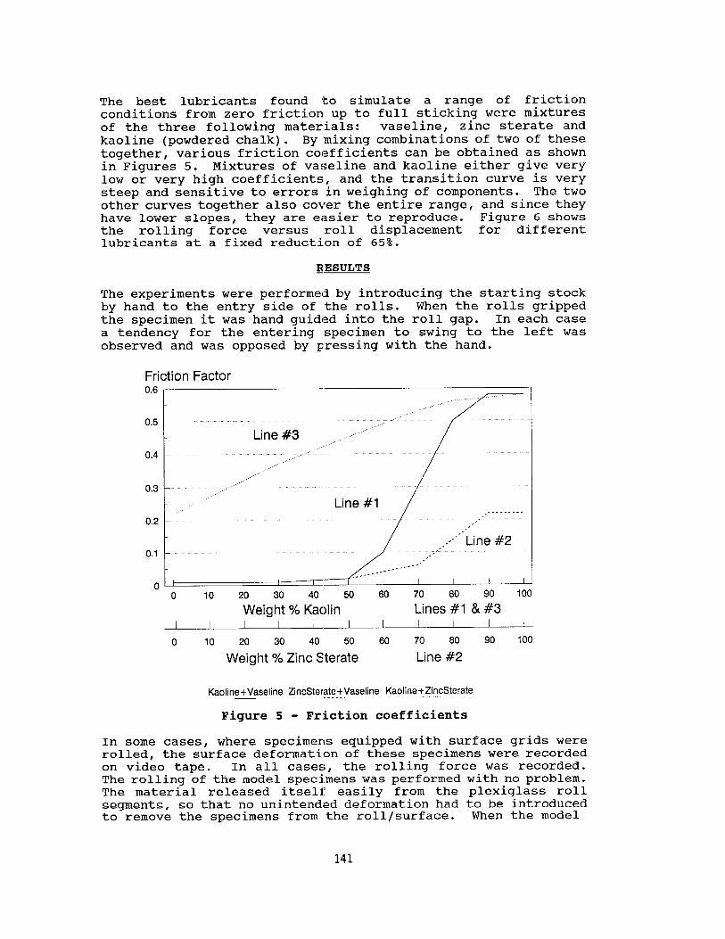
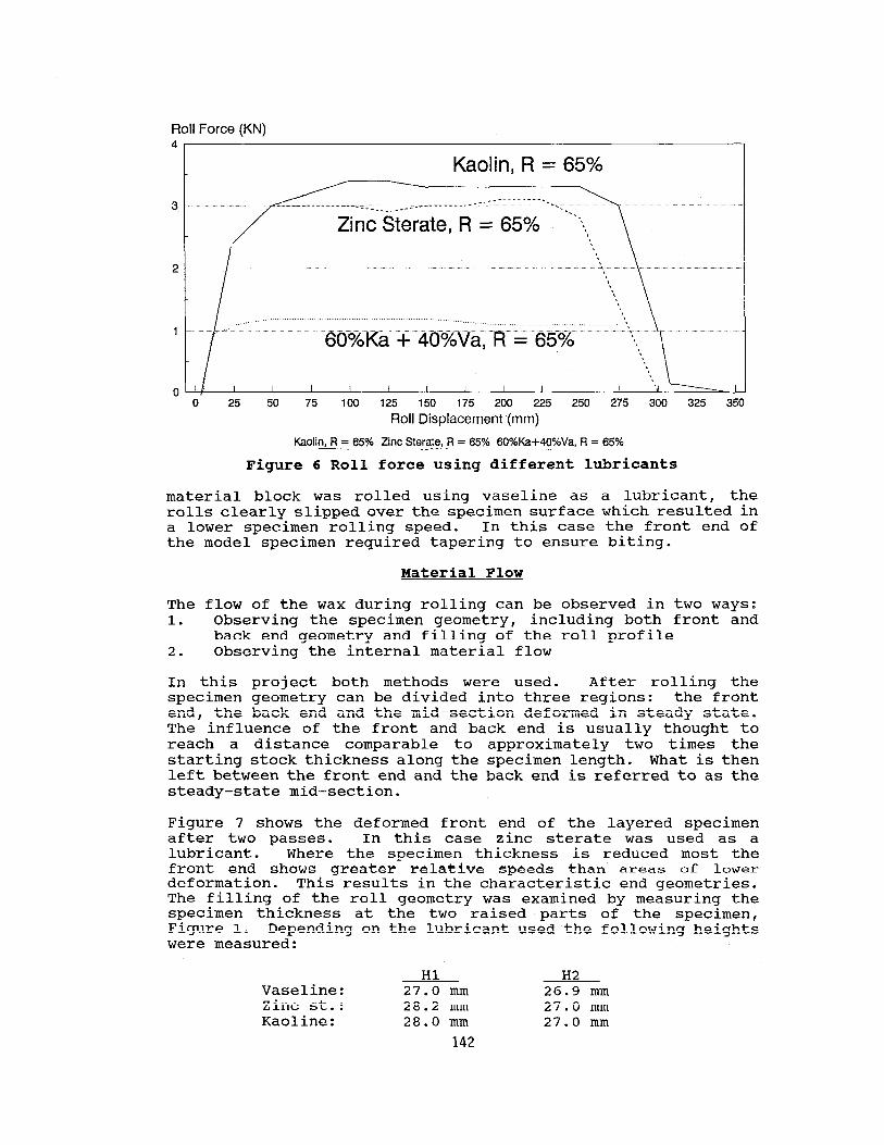
The best lubricants found to simulate a range of friction conditions from zero friction up to full sticking were mixtures of the three following materials: Vaseline, zinc sterate and kaoline (powdered chalk). By mixing combinations of two of these together, various friction coefficients can be obtained as shown in Figures 5. Mixtures of Vaseline and kaoline either give very low or very high coefficients, and the transition curve is very steep and sensitive to errors in weighing of components. The two other curves together also cover the entire range, and since they have lower slopes, they are easier to reproduce. Figure 6 shows the rolling force versus roll displacement for different lubricants at a fixed reduction of 65%.
_RESULTS
The experiments were performed by introducing the starting stock by hand to the entry side of the rolls. When the rolls gripped the specimen it was hand guided into the roll gap. In each case a tendency for the entering specimen to swing to the left was observed and was opposed by pressing with the hand.
Friction Factor 0.6
0.5 -
0.4 -
,..’ 0.3 ~
0.2 -” ..’
0.1 -
n ’ I 0 10 20 30 40 50 60 70 60 90 100
Weight % Kaolin Lines #l & #3 I I I I I I I I I I I
0 10 20 30 40 50 60 70 60 90 100
Weight % Zinc Sterate Line #2
Kaoline+Vaseline ZincSterate+Vaseline Kaoline+ZincSterate _____.
Figure 5 - Friction coefficients
In some cases, where specimens equipped with surface grids were rolled, the surface deformation of these specimens were recorded on video tape. In all cases, the rolling force was recorded. The rolling of the model specimens was performed with no problem. The material released itself easily from the plexiglass roll segments, so that no unintended deformation had to be introduced to remove the specimens from the roll/surface. When the model
141
Roll Force (KN) 4
Kaolin, R = 65% /
_-_________- ______..______.. --_. ate, R = 65% ..
,,,,... ... ‘.. ..“““““““““,“’ ““““““’ ” “.“““““““‘...” ... .- . 60%Ka + 40%Va, R = 65%
25 50 75 100 125 150 175 200 225 250 275 300 325 350
Roll Displacement (mm)
Kaolin, R = 65% Zinc Sterate, R = 65% 6O%Ke+4O%Va, R = 65% ______
Figure 6 Roll force using different lubricants
material block was rolled using Vaseline as a lubricant, the rolls clearly slipped over the specimen surface which resulted in a lower specimen rolling speed. In this case the front end of the model specimen required tapering to ensure biting.
Material Flow
The flow of the wax during rolling can be observed in two ways: 1. Observing the specimen geometry, including both front and
back end geometry and filling of the roll profile 2. Observing the internal material flow
In this project both methods were used. After rolling the specimen geometry can be divided into three regions: the front end, the back end and the mid-section deformed in steady state. The influence of the front and back end is usually thought to reach a distance comparable to approximately two times the starting stock thickness along the specimen length. What is then left between the front end and the back end is referred to as the steady-state mid-section.
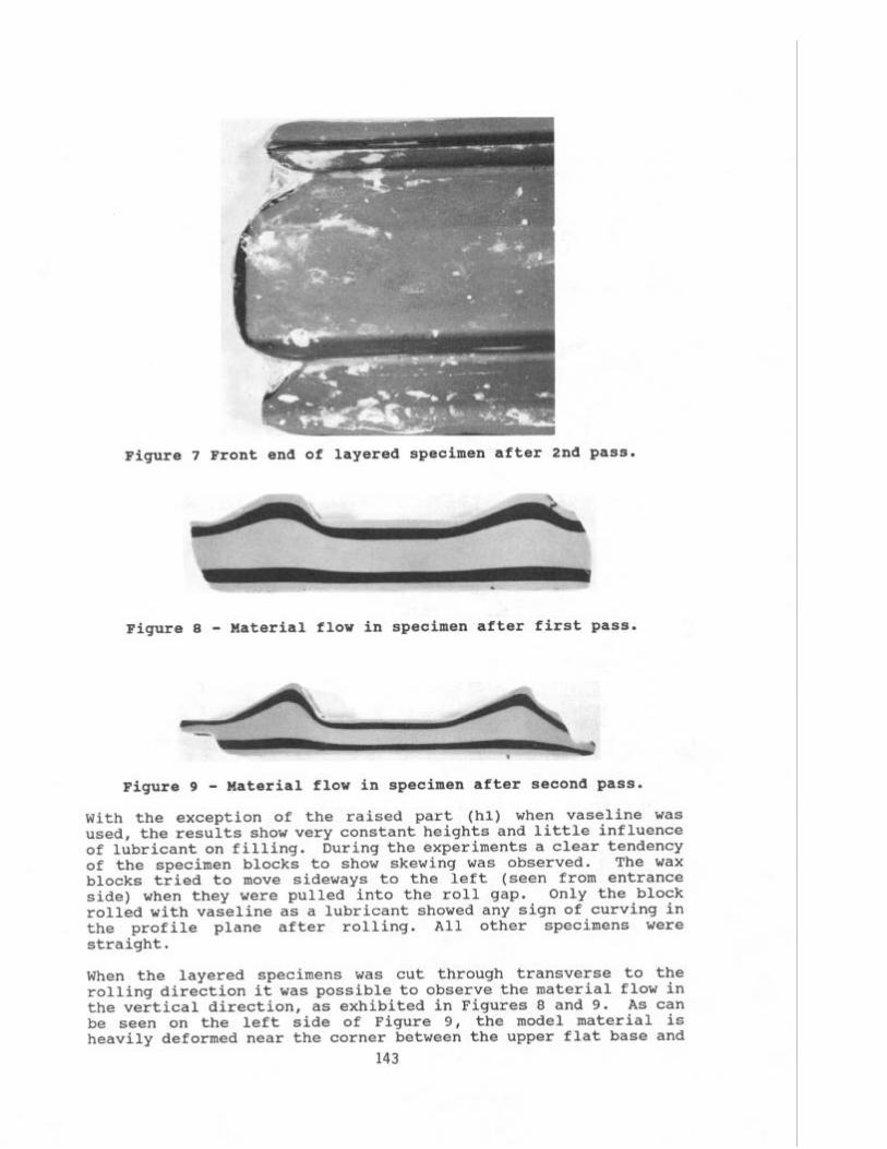
Figure 7 shows the deformed front end of the layered specimen after two passes. In this case zinc sterate was used as a lubricant. Where the specimen thickness is reduced most the front end shows greater relative speeds than areas of lower deformation. This results in the characteristic end geometries. The filling of the roll geometry was examined by measuring the specimen thickness at the two raised parts of the specimen, Figure 1. Depending on the lubricant used the following heights were measured:
Hl H2 Vaseline: 27.0 mm 26.9 mm Zinc st.: 28.2 mm 27.0 mm Kaoline: 28.0 mm 27.0 mm
142
w .w .- O”‘$
.- -
Figure 7 Front end of layered specimen after 2 nd pass.
Figure 8 - Material flow in specimen after first pass.
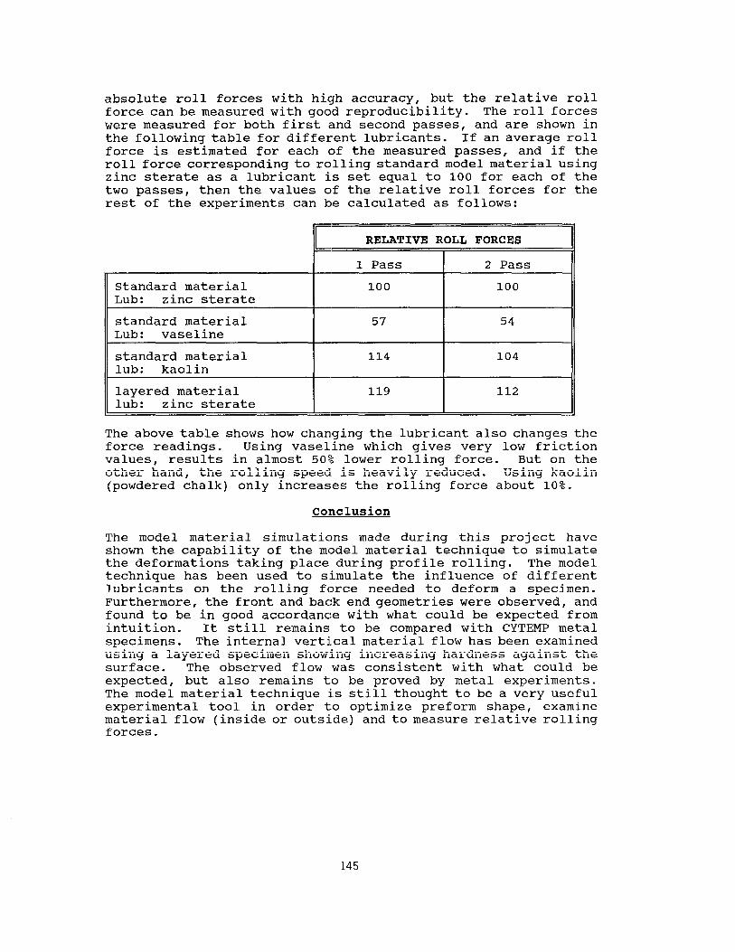
Figure 9 - Material flow in specimen after second pass.
With the exception of the raised part (hl) when Vaseline was used, the results show very constant heights and little influence of lubricant on filling. During the experiments a clear tendency of the specimen blocks to show skewing was observed. The wax blocks tried to move sideways to the left (seen from entrance side) when they were pulled into the roll gap. Only the block rolled with Vaseline as a lubricant showed any sign of curving in the profile plane after rolling. All other specimens were straight.
When the layered specimens was cut through transverse to the rolling direction it was possible to observe the material flow in the vertical direction, as exhibited in Figures 8 and 9. As can be seen on the left side of Figure 9, the model material is heavily deformed near the corner between the upper flat base and
143
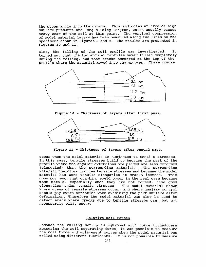
the steep angle into the groove. This indicates an area of high surface pressure and long sliding lengths, which usually causes heavy wear of the roll at this point. The vertical compression of model material layers has been measured along two lines on the specimens shown in Figures 8 and 9. The results are presented in Figures 10 and 11.
Also, the filling of the roll profile was investigated. It turned out that the two angular profiles never filled completely during the rolling, and that cracks occurred at the top of the profile where the material moved into the grooves. These cracks
I I 3.8 mm
mm I
Figure 10 - Thickness of layers after first pass.
Figure 11 - Thickness of layers after second pass.
occur when the model material is subjected to tensile stresses. In this case, tensile stresses build up because the part of the profile where the angular extensions are placed are less deformed (elongated) than the surrounding material. The surrounding material therefore induces tensile stresses and because the model material has zero tensile elongation it cracks instead. This does not mean that cracking would occur in the real case because most metals, especially when they are hot formed, have good elongation under tensile stresses. The model material shows where areas of tensile stresses occur, and where quality control should pay extra attention when examining the part surface after deformation. Therefore the model material can also be used to detect areas where cracks due to tensile stresses can, but not necessarily will, occur.
Relative Roll Forces
Because the rolling set-up is equipped with force transducers measuring the roll separating force, it was possible to measure the roll force - displacement curves when the model material was rolled using different lubricants. It is not possible to measure
144
absolute roll forces with high accuracy, but the relative roll force can be measured with good reproducibility. The roll forces were measured for both first and second passes, and are shown in the following table for different lubricants. If an average roll force is estimated for each of the measured passes, and if the roll force corresponding to rolling standard model material using zinc sterate as a lubricant is set equal to 100 for each of the two passes, then the values of the relative roll forces for the rest of the experiments can be calculated as follows:
II RELATIVE ROLL FORCES
Standard material Lub: zinc sterate
standard material Lub: Vaseline
standard material
1 Pass 2 Pass
100 100
57 54
114 104 lub: kaolin
layered material lub: zinc sterate
119 112
The above table shows how changing the lubricant also changes the force readings. Using Vaseline which gives very low friction values, results in almost 50% lower rolling force. But on the other hand, the rolling speedL is heavily reduced. Using kaolin (powdered chalk) only increases the rolling force about 10%.
Colnclusion
The model material simulations made during this project have shown the capability of the model material technique to simulate the deformations taking place during profile rolling. The model technique has been used to simulate the influence of different lubricants on the rolling force needed to deform a specimen. Furthermore, the front and back end geometries were observed, and found to be in good accordance with what could be expected from intuition. It still remains to be compared with CYTEMP metal specimens. The internal vertical material flow has been examined using a layered specimen showing increasing hardness against the surface. The observed flow was consistent with what could be expected, but also remains to be proved by metal experiments. The model material technique is still thought to be a very useful experimental tool in order to optimize preform shape, examine material flow (inside or outside) and to measure relative rolling forces.
145