Embed Size (px)
Citation preview
1
CONTROLLED POLYMERISATION AND INDUSTRIAL
APPLICATION OF POLY(2-CHLORO-1,3-BUTADIENE)
by
Nicola Pullan
Doctor of Philosophy
Aston University
Chemical Engineering and Applied Chemistry
June 2014
©Nicola Pullan, 2014
Nicola Pullan asserts her moral right to be identified as the author of this thesis.
This copy of the thesis has been supplied on condition that anyone who consults it is understood to
recognise that its copyright rests with its author and that no quotation from the thesis and no
information derived from it may be published without appropriate permission or acknowledgement.
2
Aston University
Controlled Polymerisation and Industrial Application of
Poly(2-Chloro-1,3-Butadiene)
Nicola Pullan
Doctor of Philosophy
2014
Poly(2-chloro-1,3-butadiene) (PCB, polychloroprene) has wide-ranging applications asneoprene rubber. Favourable chemical and physical properties in the material are attributedto a three-dimensional network of polymer chains, which is realised through cross-linking.Ethylene thiourea (ETU) and zinc oxide (ZnO) are the standard reagents which facilitate thisin industrial processes. However, ETU is a suspected carcinogen and its usage is due tobecome severely restricted, so much so that the future production of neoprene rubber is atrisk. Hence, an alternative, non-toxic cross-linking agent is required which can cross-linkPCB in the same fashion. The way in which the ETU/ZnO system functions must first beunderstood before a replacement can be proposed. Thus, mechanistic studies were initiallyundertaken with PCB oligomers in order to elucidate the reaction.
To this end, a synthetic protocol was established for 2-chloro-1,3-butadiene (CB) and themonomer was subsequently adopted in numerous polymerisation reactions. Investigationsinto the reversible addition-fragmentation chain transfer (RAFT) polymerisation of CBproceeded to predefine low molecular weight PCB. A successful procedure was realised,employing 2-cyano-2-propylbenzodithioate (CPD) CTA and conditions which were able tofurnish <1000 g/mol to 50,000 g/mol, low dispersity PCB in a controlled manner. Thisinvention was novel in that PCB has historically been synthesised via conventional(uncontrolled) free radical techniques.
PCB oligomers were adopted in cross-linking reactions with ETU and various modelcompounds, alone, and with ZnO, to aid the interpretation of the ETU/ZnO mechanism.Spectroscopic analyses and the observation of by-products revealed that three disparatereactions occur; ETU and ZnO were found to act both synergistically and independently ofeach other. A newly-proposed mechanism describes activation of the polymer chain by ZnOand subsequent reaction through sulfur. As a result of this discovery, alternative compoundshave been tested and found capable of cross-linking PCB.
In a second industrial study, the eradication of allergy-causing cross-linking additives for PCBlatex (gloves) was investigated. PCB latex films were generated under various conditionsand the materials physically tested. A novel amine-dithiocarbamate complex, combined witha xanthogen polysulfide, afforded comparable properties in PCB latex and as such is apotential replacement system.
Keywords: Polychloroprene; Ethylene thiourea; Cross-linking; RAFT; Latex
3
List of Publications
N. Pullan, M. Liu and P. D. Topham, Reversible Addition-Fragmentation Chain Transfer
Polymerization of 2-Chloro-1,3-Butadiene, Polymer Chemistry, 2013, 4, 2272-2277.
D. T. W. Toolan, N. Pullan, M. J. Harvey, P. D. Topham and J. R. Howse, In Situ Studies of
Phase Separation and Crystallization Directed by Marangoni Instabilities During Spin-
Coating, Advanced Materials, 2013, 25, 7033-7037.
K. I. Berry, M. Liu, K. Chakraborty, N. Pullan, A. West, C. Sammon and P. D. Topham, A
New Mechanism for Cross-linking Polychloroprene with Ethylene Thiourea and Zinc Oxide,
Rubber Chemistry and Technology, Accepted.
4
Acknowledgements
My sincere thanks go to Dr. Paul Topham, who provided a great deal of guidance and
support throughout my time at Aston.
The EPSRC are acknowledged for funding this project through a CASE studentship with
Robinson Brothers Ltd. (RBL), West Bromwich. I am grateful for the help of my co-workers at
RBL, in particular Dr. Max Liu. The various FP7-funded SafeRubber consortium members,
especially PERA Technology, are also recognised for their input.
Dr. Keith Berry has been invaluable to this project, notably for the cross-linking studies, and
was a superb companion during the numerous (often extensive) meetings. Members of the
Topham group, past and present, have provided endless amusement and I am thankful for
their support and friendship.
It has been a genuine pleasure to be a part of the CEAC department of Aston University,
where the students and staff alike create a friendly, fun atmosphere in which to work. All of
my friends, and the numerous times we have enjoyed together, will be remembered with
fondness. Rarely did a day go by where I didn’t smile or laugh because of you.
Special thanks go to Prof. Brian Tighe and BRU for use of their FTIR instrument. Dr. Jon
Howse and Daniel Toolan, of The University of Sheffield, are also acknowledged for spin-
coating collaboration.
Without a doubt, those most deserving of my appreciation are my family. Always there for me
and wanting to help in any way possible, through everything and anything, they have been
an ever-present rock. Mum and Dad, words cannot describe how proud I am to be yours. I
love you all dearly.
5
Abbreviations
AIBN α,α'-azoisobutyronitrile
ATRP atom transfer radical polymerisation
nBA n-butyl acrylate
BIIR bromobutyl rubber
Bz benzyl
CB 2-chloro-1,3-butadiene
CDCl3 deuterated chloroform
CMPCD cyanomethyl methyl(phenyl)carbamodithioate
CPD 2-cyano-2-propylbenzodithioate
CTA chain transfer agent
Ð (molecular weight) dispersity
DAB 1,4-diaminobutane
DBTU dibutyl thiourea
DDMAT S-1-dodecyl-S′-(α,α′-dimethyl-α′′-acetic acid)trithiocarbonate
DIBPO diisobutyryl peroxide
DIXP diisopropyl xanthogen polysulfide
DPG diphenyl guanidine
DPTU diphenyl thiourea
ETU ethylene thiourea
EU ethylene urea
FTIR fourier transform infrared
GPC gel permeation chromatography
HCl hydrochloric acid
6
LAM less-activated monomer
MAM more-activated monomer
MFA multi-functional additive
MMA methyl methacrylate
Mn number-average molecular weight
Mw weight-average molecular weight
NMP nitroxide-mediated radical polymerisation
NMR nuclear magnetic resonance spectroscopy
NR natural rubber
ODT 1,8-octanedithiol
PCB poly(2-chloro-1,3-butadiene)
phr parts per hundred rubber
PIP piperazine
PNA proposed new accelerator
ppm parts per million
PRE persistent radical effect
PSt polystyrene
PTC phase-transfer catalyst
RAFT reversible addition-fragmentation chain transfer
SMO sodium salt of sulfated methyl oleate
St styrene
TBTA S-(thiobenzoyl)thioglycolic acid
TbuT tetrabutylthiuram disulfide
TBzTD tetrabenzylthiuram disulfide
TETD tetraethylthiuram disulfide
7
THF tetrahydrofuran
TMS trimethylsilane
TMTD tetramethylthiuram disulphide
TMTM tetramethylthiuram monosulphide
TSC total solids content
UTS ultimate tensile strength
VC vinyl chloride
WAQ sodium alkyl sulfate
ZnCl2 zinc chloride
ZnO zinc oxide
8
Contents
Thesis Summary 2
List of Publications 3
Acknowledgements 4
Abbreviations 5
Contents 8
List of Tables 13
List of Figures 15
List of Schemes 20
List of Equations 22
Chapter 1 Introduction 24
1.1 Definitions for polymers and polymerisation methods 24
1.1.1. Conventional (uncontrolled) free radical chain polymerisation 26
1.1.1.1. Free radical chain polymerisation mechanism 26
1.1.1.2. Other factors influencing polymerisation 29
1.1.1.2.1. Temperature 29
1.1.1.2.2. Form of polymerisation 29
1.1.1.2.3. Inhibitors/retarders 30
1.1.1.3. General features of conventional free radical chain
polymerisation 30
1.1.2. Controlled-radical polymerisation methods 31
1.1.2.1. General features of nitroxide-mediated radical polymerisation
(NMP) 34
1.1.2.2. General features of atom transfer radical polymerisation
(ATRP) 35
1.1.2.3. Reversible addition-fragmentation chain transfer
polymerisation (RAFT) 36
1.1.2.3.1. The reversible addition-fragmentation chain transfer (RAFT)
mechanism 37
1.1.2.3.2. Application of the RAFT CTA 38
1.1.2.3.3. Other reaction considerations 42
1.1.2.3.4. General features of RAFT polymerisation 44
1.2 Cross-linking 44
1.2.1. Cross-linking methods and additives in the rubber industry 45
9
1.2.1.1. The role of sulfur (and nitrogen) -containing compounds as
accelerators 46
1.2.1.2. The role of zinc oxide (ZnO) in cross-linking 47
1.2.1.3. The role of multi-functional additives (MFAs) in cross-linking 48
1.2.2. Cross-linking poly(2-chloro-1,3-butadiene) 48
1.2.2.1. Typical PCB cross-linking additives 49
1.2.2.2. PCB cross-linking theories – ZnO alone 51
1.2.2.3. PCB cross-linking theories – ETU alone 53
1.2.2.4. PCB cross-linking theories – ETU and ZnO 54
1.3 Latex technology 55
1.3.1. Emulsion polymerisation 55
1.3.1.1. Emulsion polymerisation components 55
1.3.1.2. Emulsion polymerisation mechanism 56
1.3.1.2.1. The Harkins theory 57
1.3.1.2.2. The Smith and Ewart theory 58
1.3.2. Latex formulation 59
1.3.2.1. Formulations 59
1.3.2.2. Latex compounding 61
1.3.2.2.1. Latex dipping 62
1.3.2.2.2. Latex characterisation 63
1.3.2.3. Applications of latexes 64
1.3.3. Poly(2-chloro-1,3-butadiene) latex 65
1.3.3.1. PCB latex composition 66
1.3.3.2. PCB latex applications 67
1.4 Aims 70
1.5 References 71
Chapter 2 Materials and experimental methods 77
2.1 Materials 77
2.2 Experimental methods 79
2.2.1. Synthesis of 2-chloro-1,3-butadiene 79
2.2.2. Synthesis of poly(2-chloro-1,3-butadiene) via uncontrolled
polymerisation 79
2.2.3. Synthesis of poly(2-chloro-1,3-butadiene) via RAFT
polymerisation 80
2.2.3.1. Chain extension experiment 81
2.2.4. Compounding and cross-linking of poly(2-chloro-1,3-butadiene)
oligomers 81
10
2.2.5. Poly(2-chloro-1,3-butadiene) latex compounding 82
2.2.5.1. Preparation of PNA-5 dispersion 84
2.2.6. Preparation of poly(2-chloro-1,3-butadiene) latex films 85
2.3 Characterisation methods 86
2.3.1. Nuclear Magnetic Resonance Spectroscopy 86
2.3.1.1. Monitoring monomer conversion 87
2.3.2. Gel Permeation Chromatography 88
2.3.3. Fourier Transform Infrared Spectroscopy 89
2.3.4. Viscosity measurements 89
2.3.5. Tensometer 89
2.4 References 90
Chapter 3 RAFT Polymerisation of 2-chloro-1,3-butadiene 92
3.1 Synthesis of 2-chloro-1,3-butadiene 92
3.1.1. Varying sodium hydroxide concentration 93
3.1.2. Water as a by-product 94
3.1.3. Variable yields in the synthesis of 2-chloro-1,3-butadiene 95
3.1.4. NMR Characterisation of 2-chloro-1,3-butadiene 96
3.1.5. Stability of 2-chloro-1,3-butadiene 97
3.2 Synthesis of poly(2-chloro-1,3-butadiene) via uncontrolled
polymerisation 100
3.2.1. The effect of monomer purity 101
3.2.2. Polymerisation 102
3.2.3. Spectroscopic characterisation of poly(2-chloro-1,3-butadiene) 103
3.3 Synthesis of poly(2-chloro-1,3-butadiene) via RAFT polymerisation 108
3.3.1. Selection of chain transfer agents (CTAs) 109
3.3.1.1. S-(Thiobenzoyl)thioglycolic acid (TBTA) 110
3.3.1.2. Cyanomethyl methyl(phenyl)carbamodithioate (CMPCD) 115
3.3.1.3. S-1-Dodecyl-S′-(α,α′-dimethyl-α′′-acetic acid)trithiocarbonate
(DDMAT) 119
3.3.1.4. 2-Cyano-2-propylbenzodithioate (CPD) 123
3.3.2. DDMAT and CPD RAFT polymerisation reactions in bulk 127
3.3.3. Optimum system 131
3.4 Conclusion and future work 136
3.5 References 137
Chapter 4 Spectroscopic analysis of the cross-linking of poly(2-chloro-1,3-
butadiene) 140
11
4.1 Cross-linking poly(2-chloro-1,3-butadiene) 140
4.1.1. Cross-linking PCB with ETU 143
4.1.2. Cross-linking PCB with ZnO 144
4.1.3. Cross-linking PCB with ETU and ZnO 147
4.1.4. Cross-linking PCB with model compounds and other standard
accelerators 153
4.1.4.1. Cross-linking PCB with model compounds 153
4.1.4.2. Cross-linking PCB with model compounds combined with ZnO 156
4.1.4.3. Cross-linking PCB with tetrabutylthiuram disulfide (TbuT) 159
4.1.4.4. Cross-linking PCB with tetrabutylthiuram disulfide (TbuT)
combined with ZnO 160
4.1.5. Conclusions for the current cross-linking mechanism of poly(2-
chloro-1,3-butadiene) 161
4.1.5.1. Cross-linking of PCB by ETU compared with other compounds 161
4.1.5.2. The ETU/ZnO mechanism of cross-linking PCB 162
4.1.6. Towards a safer accelerator system for cross-linking poly(2-
chloro-1,3-butadiene) 165
4.2 References 169
Chapter 5 Poly(2-chloro-1,3-butadiene) latex development 172
5.1 Introduction 172
5.2 PCB latex films from the standard DPTU/DPG accelerator system 174
5.3 Alternative accelerator system for PCB latex comprising PNA-5 176
5.3.1. Development and stability of the PNA-5 dispersion reagent 177
5.3.2. PCB latex formulated with PNA-5 alone 179
5.3.3. PCB latex formulated with PNA-5 and 1,4-MFA 181
5.3.4. PCB latex formulated with PNA-5 and DIXP 184
5.3.5. PCB latex formulated with PNA-5 and TBzTD 187
5.4 Alternative accelerator system comprising DIXP and PNA-8 190
5.5 Comparisons for the development of poly(2-chloro-1,3-butadiene)
latex films 193
5.5.1. Effect of reducing ZnO in PCB latex formulations 194
5.5.2. Summary of accelerator systems for PCB latex 199
5.5.3. Further PCB latex development work 202
5.6 References 204
Chapter 6 Conclusions and future work 206
6.1 Outline of the project 206
12
6.2 Conclusions 207
6.2.1. Synthesis of 2-chloro-1,3-butadiene 207
6.2.2. Synthesis of poly(2-chloro-1,3-butadiene) 208
6.2.2.1. Uncontrolled polymerisation of 2-chloro-1,3-butadiene 208
6.2.2.2. RAFT polymerisation of 2-chloro-1,3-butadiene 209
6.2.3. Industrial applications of poly(2-chloro-1,3-butadiene) 212
6.2.3.1. Cross-linking poly(2-chloro-1,3-butadiene) 212
6.2.3.1.1. A safer accelerator system for cross-linking PCB rubber 214
6.2.3.2. Poly(2-chloro-1,3-butadiene) latex development 215
6.2.3.2.1. The effect of ZnO in PCB latex films 215
6.2.3.2.2. New accelerators for the production of PCB latex films 216
6.3 Future work 217
6.3.1. Further development of the 2-chloro-1,3-butadiene synthetic
protocol 217
6.3.2. Future studies for the RAFT polymerisation of 2-chloro-1,3-
butadiene 218
6.3.3. Optimisation of oligomer cross-linking experiments 218
6.3.4. Further development of poly(2-chloro-1,3-butadiene) latex 219
6.4 References 220
13
List of Tables
Table 1.1. Additives commonly used in the industrial cross-linking of rubbers. 46
Table 1.2. Common organic accelerators adopted in rubber cross-linking. 47
Table 1.3. Reagents typically employed in latex formulation. 60
Table 1.4. Summary of latex applications. 65
Table 1.5. Reagents typically employed in PCB latex formulations, as taken
predominantly from Blackley. 66
Table 1.6. Accelerators which are latex glove allergens. 68
Table 2.1. List of reagents adopted in the syntheses of 2-chloro-1,3-butadiene (CB)
and polymers thereof (PCB). 77
Table 2.2. List of reagents adopted in the poly(2-chloro-1,3-butadiene) cross-
linking trials. 78
Table 2.3. List of aqueous dispersions adopted for the poly(2-chloro-1,3-butadiene)
latex films. 78
Table 2.4. Reaction mixtures adopted in PCB oligomer cross-linking studies, where
levels are given in phr. 82
Table 2.5. Formulation details for the compounding of PCB latex films (depicted as
A – I), where quantities are given in parts per hundred (phr). 83
Table 2.6. Formulation details for the compounding of PCB latex films with the
DIXP/PNA-8 accelerator system (I); adjustment to 40 % TSC is outlined. 84
Table 2.7. Formulation details for (35 % w/w) PNA-5 dispersion. 85
Table 2.8. Approximate percentage monomer conversion during the CPD/THF
RAFT polymerisation, by comparison of 1H NMR integrals relating to the
vinyl and alkene protons of CB and PCB. 88
Table 3.1. Table showing how varying sodium hydroxide concentrations in CB
syntheses affected percentage yields. 93
Table 3.2. Experimental data highlighting the variable yields obtained during the
synthesis of CB. 95
Table 3.3. Approximate percentage degradation of uninhibited CB (a) by
comparison of 1H NMR integrals relating to vinyl and alkene protons in
CB and PCB. 100
Table 3.4. Experimental data for the (uncontrolled) polymerisation of CB. 102
Table 3.5. FTIR peaks assigned in PCB, as aided by the literature. 105
14
Table 3.6. Comparison of initial apparent rate constants, kapp, in the RAFT
polymerisations of CB employing DDMAT and CPD CTAs (obtained
under solution and bulk conditions). 131
Table 3.7. Comparison of theoretical (Mnth) and experimental (Mn
GPC) molecular
weights, and dispersities (Ð), obtained for the optimum CB RAFT
system targeting different degrees of polymerisation (Dp). 133
Table 4.1. FTIR peaks assigned in PCB, as aided by the literature. 142
Table 4.2. List of additives used in the cross-linking studies. 142
Table 4.3. Model compounds and accelerators adopted in PCB cross-linking
studies. 153
Table 4.4. List of original potential new accelerators (PNAs) for cross-linking PCB,
designated by the SafeRubber consortium. 166
Table 5.1. Individual components in the PCB latex formulations. 173
Table 5.2. Accelerators adopted in the PCB latex formulations. 174
Table 5.3. Formulation details for the compounding of PCB/DPTU/DPG latex
films (A). 175
Table 5.4. Tensile results for the PCB/DPTU/DPG latex films (A). 176
Table 5.5. Formulation details for the compounding of PCB/PNA-5 latex films (B). 180
Table 5.6. Tensile results for the PCB/PNA-5 latex films (B). 181
Table 5.7. Formulation details for the compounding of PCB/PNA-5/1,4-MFA latex
films (C and D). 182
Table 5.8. Tensile results for the PCB/PNA-5/1,4-MFA latex films (C and D). 182
Table 5.9. Formulation details for the compounding of PCB/PNA-5/DIXP latex films
(E and F). 185
Table 5.10. Tensile results for the PCB/PNA-5/DIXP latex films (E and F). 185
Table 5.11. Formulation details for the compounding of PCB/PNA-5/TBzTD latex
films (G and H). 188
Table 5.12. Tensile results for the PCB/PNA-5/TBzTD latex films (G and H). 189
Table 5.13. Formulation details for the compounding of PCB/DIXP/PNA-8 latex
films (I). 191
Table 5.14. Tensile results for the PCB/DIXP/PNA-8 latex films (I). 192
Table 5.15. Overall tensile results table for the PCB latex films furnished using
various accelerator systems, where mean values are quoted plus/minus
the standard deviations. 200
15
List of Figures
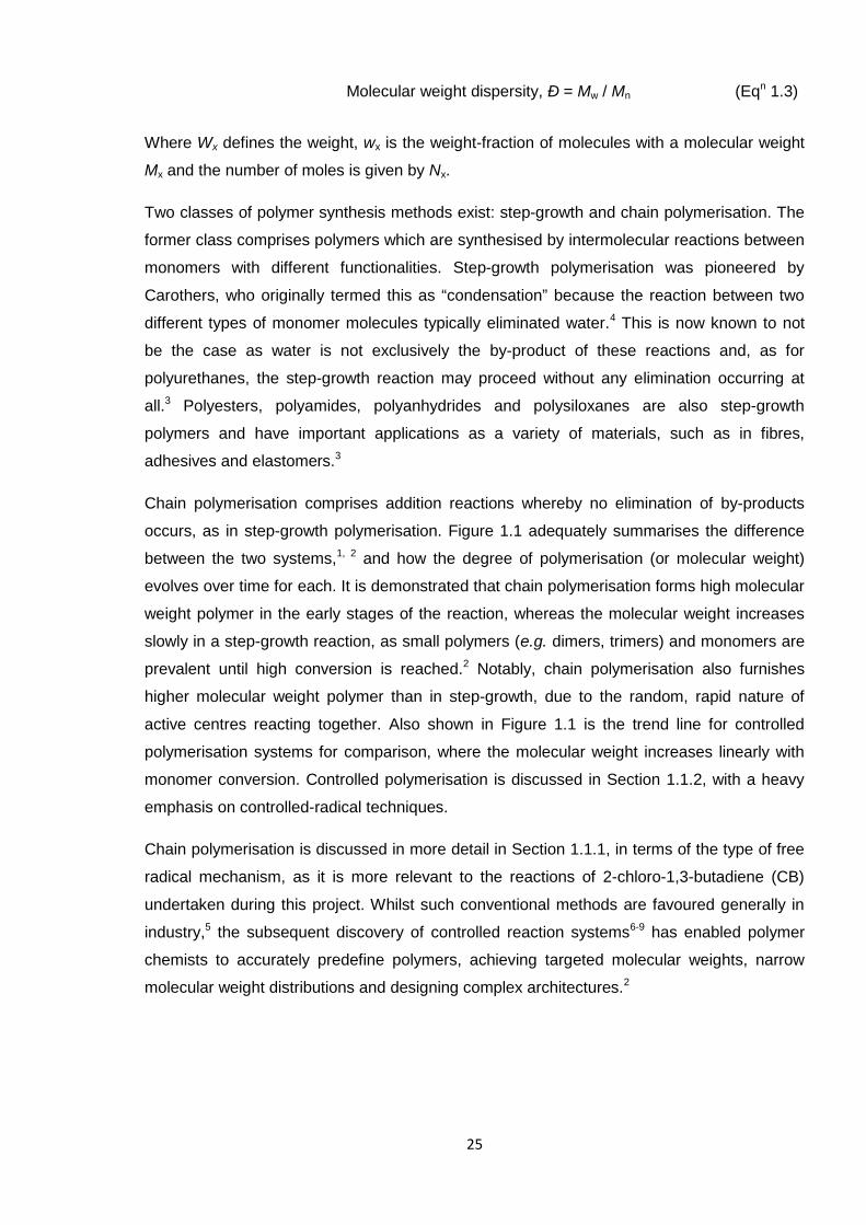
Figure 1.1. Graph illustrating the change in degrees of polymerisation (Dp) with
monomer conversion for the different types of polymerisation reactions. 26
Figure 1.2. 1-Methoxy-1-trimethylsiloxy-2-methyl-1-propene initiator adopted in
group transfer polymerisation (GTP). 32
Figure 1.3. Generic structure of the RAFT CTA. 36
Figure 1.4. Generic structures for the types of CTAs employed in RAFT. 39
Figure 1.5. General guidelines for designing the RAFT CTA, as adapted from the
literature. 40
Figure 1.6. Summary of the types of monomers polymerised in RAFT. 42
Figure 1.7. Generic structure for a chemically cross-linked polymer network. 45
Figure 1.8. Inorganic accelerator systems comprising the zinc dication: zinc
dibutyldithiocarbamate (ZDBC) and zinc isopropylxanthate (ZIX). 48
Figure 1.9. General representation of a multi-functional additive (MFA). 48
Figure 1.10. The four isomers of poly(2-chloro-1,3-butadiene) (PCB). 49
Figure 1.11. Comparison of the structures of 1,4-cis-polyisoprene and 1,4-trans-PCB 50
Figure 1.12. Structure of PCB cross-linked via bis-alkylation with ethylene thiourea
(ETU), as suggested by Kovacic. 53
Figure 1.13. Structures of ETU and piperazine. 53
Figure 1.14. Generic structures for a surfactant molecule and a micelle. 56
Figure 1.15. General representation of an emulsion polymerisation system, as
adapted from the literature. 57
Figure 1.16. Illustration of the latex compounding/dipping procedure. 63
Figure 1.17. Simplified diagram of a typical tensometer. 64
Figure 1.18. Structure of diisopropyl xanthogen polysulfide (DIXP),
where n = 3, 4 or 5. 69
Figure 2.1. The dipping procedure adopted for the preparation of PCB latex films. 86
Figure 2.2. Comparative 1H NMR spectra (in CDCl3) illustrating the progress of CB
polymerisation (RAFT, in CPD/THF conditions) through the appearance
of PCB vinyl protons at 5 – 6 ppm (z) and the disappearance of the
monomer vinyl proton (y). 87
Figure 2.3. Simplified diagram of a typical tensometer. 90
Figure 3.1. 1H NMR spectrum of CB before (b) and after (a) drying over MgSO4. 94
Figure 3.2. Pure CB 1H NMR spectrum (a) and PENDANT 13C NMR spectrum (b). 97
16
Figure 3.3. Comparative 1H NMR spectra (in CDCl3) showing the self-
polymerisation of CB (a) neat and (b) with 0.1% (w/w) phenothiazine
(3.1), under ambient conditions. 99
Figure 3.4. Comparative GPC data (normalised RI response) for poly(2-chloro-1,3-
butadiene) (PCB) originating from pure (___) and crude (---) monomer. 101
Figure 3.5. The various isomers possible in PCB. 104
Figure 3.6. FTIR spectrum of PCB. 104
Figure 3.7. PENDANT 13C NMR spectrum of PCB. 105
Figure 3.8. 1H NMR spectra of (a) PCB, indicating the major 1,4-trans isomer, and
(b) 1-dodecanethiol. 106
Figure 3.9. 1H NMR spectra of PCB, highlighting the minor signals specific to the
1,2- isomer (a), and the major polymer backbone signals (CH2, b). 107
Figure 3.10. HSQC NMR spectrum for PCB. 108
Figure 3.11. Structures of the CTAs trialled in the RAFT polymerisation of CB. 110
Figure 3.12. Styrene, St (3.2), methyl methacrylate, MMA (3.3), and n-butyl acrylate,
nBA (3.4): the monomers studied using ethyl S-(thiobenzoyl)thioacetate
(3.5), ethyl S-thiobenzoyl-2-thiopropionate (3.6) and S-
(thiobenzoyl)thioglycolic acid, TBTA (3.7), RAFT CTAs in work by
Farmer and Patten. TBTA was studied herein for CB. 112
Figure 3.13. Kinetic plots for the polymerisation of CB, in THF and xylene (50 % w/w
each), under the following conditions: [AIBN]0/[TBTA]0/[CB]0 = 0.2/1/45
at 60 °C. Where ● = Mn, □ = Ð, --- = Mnth. 113
Figure 3.14. GPC traces (normalised RI response) showing polymer formation over
time for the TBTA polymerisation systems in xylene (a) and THF (b). 114
Figure 3.15. Structures of vinyl chloride, VC, diisobutyryl peroxide, DIBPO and α,α'-
azoisobutyronitrile, AIBN. 116
Figure 3.16. Kinetic plots for the polymerisation of CB, in THF and xylene (50 % w/w
each), under the following conditions: [AIBN]0/[CMPCD]0/[CB]0 =
0.2/1/45 at 60 °C. Where ● = Mn, □ = Ð, --- = Mnth. 117
Figure 3.17. GPC traces (normalised RI response) showing polymer formation over
time for the CMPCD polymerisation systems in xylene (a) and THF (b). 118
Figure 3.18. Kinetic plots for the polymerisation of CB, in THF and xylene (50 % w/w
each), under the following conditions: [AIBN]0/[DDMAT]0/[CB]0 =
0.2/1/45 at 60 °C. Where ● = Mn, □ = Ð, --- = Mnth. 121
Figure 3.19. GPC traces (normalised RI response) showing polymer formation over
time for the DDMAT polymerisation systems in xylene (a) and THF (b). 122
17
Figure 3.20. Kinetic plots for the polymerisation of CB, in THF and xylene (50 % w/w
each), under the following conditions: [AIBN]0/[CPD]0/[CB]0 = 0.2/1/45 at
60 °C. Where ● = Mn, □ = Ð, --- = Mnth. 125
Figure 3.21. GPC traces (normalised RI response) showing polymer formation over
time for the CPD polymerisation systems in xylene (a) and THF (b). 126
Figure 3.22. Kinetic plots for the polymerisation of CB in bulk at 60 °C for DDMAT
and CPD under the following conditions: [AIBN]0/[DDMAT]0/[CB]0 =
0.2/1/45 and [AIBN]0/[CPD]0/[CB]0 = 0.2/1/113. Where ● = Mn, □ = Ð, ---
= Mnth. 129
Figure 3.23. GPC traces (normalised RI response) showing polymer formation over
time for the polymerisation systems comprising DDMAT (a) and CPD
(b). 130
Figure 3.24. Kinetic plots for the RAFT polymerisation of CB under the following
conditions: [AIBN]0/[CPD]0/[CB]0 = 0.2/1/45 at 60 °C in THF (50 % w/w). 132
Figure 3.25. GPC traces (normalised RI response) of PCB with varying molecular
weights, synthesised by RAFT using CPD at 60 °C in THF (50 % w/w). 133
Figure 3.26. GPC traces (normalised RI response) of the PCB macroCTA and the
corresponding PCB-b-PCB following chain extension using CPD CTA. 134
Figure 4.1. The four isomers of poly(2-chloro-1,3-butadiene) (PCB). 141
Figure 4.2. FTIR spectrum of PCB. 141
Figure 4.3. Representative FTIR spectrum collected during the PCB/ETU reaction,
highlighting a new peak at 1548 cm-1. 144
Figure 4.4. Representative FTIR spectrum collected during the PCB/ZnO reaction. 145
Figure 4.5. Representative FTIR spectrum collected during the PCB/ZnO reaction
(A) versus FTIR spectra of ZnCl2 (B) and ZnO (C). 147
Figure 4.6. FTIR spectra collected at the start (A) and during (B) the PCB/ETU/ZnO
reaction, with emphasis on the new peak formed at 1545 cm-1. 148
Figure 4.7. FTIR spectrum of the solid by-product from the PCB/ETU/ZnO reaction,
whereby the polymer background (neat PCB) has been subtracted. 149
Figure 4.8. FTIR spectra of the solid products from (A) the ETU/ZnO/HCl test
reaction and (B) the ETU/ZnCl2 test reaction. 150
Figure 4.9. FTIR spectra of (A) ethylene urea (EU) and (B) solid extracts from the
PCB rubber ETU/ZnO reaction performed by Berry, each displaying
carbonyl peaks in the 1670 – 1640 cm-1 region. 151
Figure 4.10. FTIR spectra collected during the PCB/PIP reaction (A) and that of the
water washed, dried final material (B), where the peaks at 1565 cm-1
and 1535 cm-1 were eradicated. 155
18
Figure 4.11. FTIR spectra, displayed in the 1750 – 525 cm-1 region, of PIP (A) and
acidified PIP (B); the highlighted 1542 cm-1 peak confirms salt formation. 156
Figure 4.12. FTIR spectra collected during the PCB/DAB/ZnO reaction, at five
minutes (A) and 60 minutes (B), where distinct changes occur in the
1600 – 1500 cm-1 region. 157
Figure 4.13. FTIR spectra collected at the start of the PCB/ODT/ZnO reaction (A),
and after 10 minutes (B), where the 1569 cm-1 peak disappears. 158
Figure 4.14. FTIR spectra collected during the PCB/TbuT reaction, where the
1486 cm-1 peak at the start (A) disappears within 30 minutes (B). 159
Figure 4.15. FTIR spectrum collected at the end of the PCB/TbuT/ZnO reaction,
highlighting a new peak at 1560 cm-1. 160
Figure 4.16. Comparison of Zn2+-complexed TbuT and PNA-5 structures, where Bu
denotes a linear butyl group. 167
Figure 4.17. FTIR spectrum of PNA-5 (A) and representative spectrum collected
during a PCB/PNA-5 cross-linking reaction (B). 168
Figure 4.18. Representative FTIR spectrum collected during the PCB/PNA-5/ZnO
cross-linking reaction, with newly formed peaks highlighted. 168
Figure 4.19. Structure of 1,4-MFA. 169
Figure 5.1. Image of the final PCB/DPTU/DPG latex film (A), which has been cut
into dumbbells prior to tensile testing. 176
Figure 5.2. The change in viscosity over time for the PNA-5 dispersion, stored at
40 °C (1, denoted by ●) and at room temperature (2, denoted by □). 178
Figure 5.3. Image of the final PCB/PNA-5 latex film (B). 181
Figure 5.4. Structure of 1,4-MFA. 181
Figure 5.5. Images of the final PCB/PNA-5/1,4-MFA latex films, whereby the
formulations comprised contrasting levels of ZnO (film C: 5 phr ZnO; film
D: 1 phr ZnO). 183
Figure 5.6. Structure of diisopropyl xanthogen polysulfide (DIXP),
where n = 3, 4 or 5. 184
Figure 5.7. Images of the final PCB/PNA-5/DIXP latex films, whereby the
formulations comprised contrasting levels of ZnO (film E: 5 phr ZnO; film
F: 1 phr ZnO). 186
Figure 5.8. Images of the final PCB/PNA-5/TBzTD latex films, whereby the
formulations comprised different levels of ZnO (film G: 5 phr ZnO; film
H: 1 phr ZnO) and film H comprised 1,4-MFA (0.5 phr). 190
Figure 5.9. Structure of 2,2'-dithio di(ethylammonium)-bis(dibenzyldithiocarbamate)
(PNA-8). 191
Figure 5.10. Image of the final PCB/DIXP/PNA-8 latex films (I). 192
19
Figure 5.11. Comparison of UTS for PCB latex films made using PNA-5 combined
with 1,4-MFA (red, C and D), DIXP (green, E and F) and TBzTD (blue,
G and H), where the latter datum represents a lower level of ZnO in
each case (1 phr versus 5 phr). Error bars indicate one standard
deviation from ten data points. The dashed line represents the industrial
standard UTS value (i.e. film A, 23.7 MPa). 195
Figure 5.12. Comparison of 300 % modulus for PCB latex films made using PNA-5
combined with 1,4-MFA (red, C and D), DIXP (green, E and F) and
TBzTD (blue, G and H), where the latter datum represents a lower level
of ZnO in each case (1 phr versus 5 phr). Error bars indicate one
standard deviation from ten data points. The dashed line represents the
industrial standard 300 % modulus value (i.e. film A, 2.40 MPa). 196
Figure 5.13. Comparison of elongation at break for PCB latex films made using PNA-
5 combined with 1,4-MFA (red, C and D), DIXP (green, E and F) and
TBzTD (blue, G and H), where the latter datum represents a lower level
of ZnO in each case (1 phr versus 5 phr). Error bars indicate one
standard deviation from ten data points. The dashed line represents the
industrial standard elongation at break value (i.e. film A, 861 %). 197
Figure 5.14. Comparison of tensile test data for PCB latex films made using
DPTU/DPG (purple, A) and DIXP/PNA-8 (orange, I). Error bars indicate
one standard deviation from ten data points. 201
Figure 6.1. Structures of the CTAs trialled in the RAFT polymerisation of CB. 209
Figure 6.2. Kinetic plots for the optimum RAFT polymerisation of CB under the
following conditions: [AIBN]0/[CPD]0/[CB]0 = 0.2/1/45 at 60 °C in THF
(50 % w/w). 210
Figure 6.3. Structure of piperazine-1-carbodithioic acid 1,3-diaminopropane
complex (PNA-5). 214
20
List of Schemes
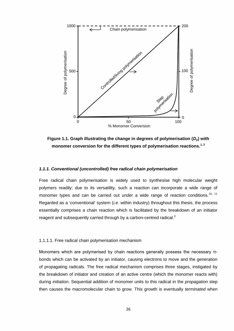
Scheme 1.1. The mechanism of conventional free radical chain polymerisation. 27
Scheme 1.2. The decomposition of α,α′–azoisobutyronitrile (AIBN). 27
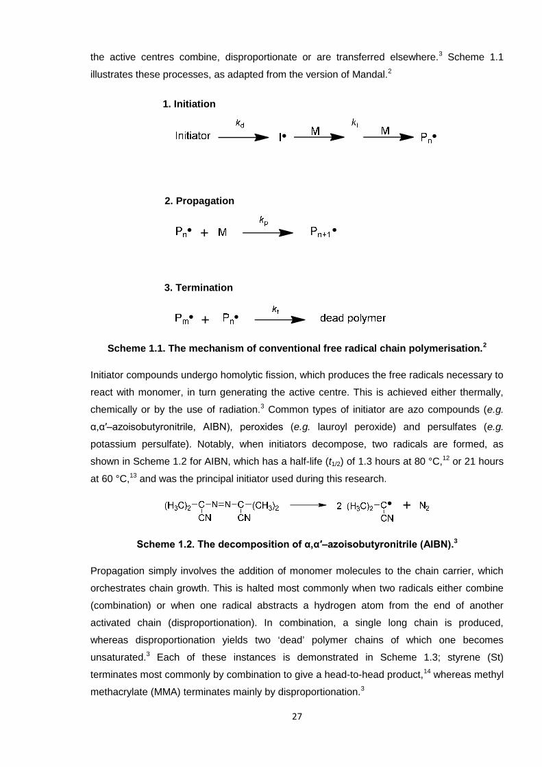
Scheme 1.3. Examples of termination by combination of styrene, St, (a) and
disproportionation of methyl methacrylate, MMA, (b). 28
Scheme 1.4. General scheme for the persistent radical effect (PRE). 33
Scheme 1.5. The method of reversible termination (deactivation) of NMP, as
mediated by the TEMPO radical. 34
Scheme 1.6. The reversible redox process of the ATRP mechanism, catalysed by a
transition metal complex. Mt represents the metal atom and L is the
ligand; Y can be a counterion or another ligand. 35
Scheme 1.7. The mechanism of RAFT polymerisation. 37
Scheme 1.8. The zwitterionic canonical form of an O-alkylxanthate (also applicable
to dithiocarbamates, where the oxygen atom is replaced by nitrogen) 40
Scheme 1.9. Allylic rearrangement of the chlorine atom in 1,2-PCB. 50
Scheme 1.10. The tautomeric forms of ethylene thiourea (ETU, 1.5). 50
Scheme 1.11. The cationic mechanism for cross-linking PCB, as facilitated by ZnO,
proposed by Desai et al. 52
Scheme 1.12. The mechanism of cross-linking PCB with ETU and ZnO, as originally
proposed by Pariser and modified from the literature. 54
Scheme 2.1. The synthesis of 2-chloro-1,3-butadiene (CB) by the
dehydrochlorination of 3,4-dichloro-1-butene, where PTC denotes a
phase-transfer catalyst. 79
Scheme 2.2. The uncontrolled polymerisation of 2-chloro-1,3-butadiene (CB) using
1-dodecanethiol CTA (the main 1,4-trans polymer isomer
configuration is shown). 79
Scheme 2.3. The RAFT polymerisation of 2-chloro-1,3-butadiene (CB,) using
2-cyano-2-propylbenzodithioate, CPD, CTA (the main 1,4-trans
polymer isomer configuration is shown). 80
Scheme 3.1. The synthesis of 2-chloro-1,3-butadiene (CB) by the
dehydrochlorination of 3,4-dichloro-1-butene, where PTC denotes a
phase-transfer catalyst. 92
Scheme 3.2. The dehydrochlorination of 3,4-dichloro-1-butene by base, the E1
reaction. 94
21
Scheme 3.3. The uncontrolled polymerisation of 2-chloro-1,3-butadiene (CB) using
1-dodecanethiol CTA (the main 1,4-trans polymer isomer
configuration is shown). 100
Scheme 3.4. The RAFT polymerisation of 2-chloro-1,3-butadiene (CB) using S-
(thiobenzoyl)thioglycolic acid, TBTA, CTA (the main 1,4-trans polymer
isomer configuration is shown). 112
Scheme 3.5. The RAFT polymerisation of 2-chloro-1,3-butadiene (CB) using
cyanomethyl methyl(phenyl)carbamodithioate, CMPCD, CTA (the
main 1,4-trans polymer isomer configuration is shown). 116
Scheme 3.6. The RAFT polymerisation of 2-chloro-1,3-butadiene (CB) using S-1-
dodecyl-S′-(α,α′-dimethyl-α′′-acetic acid)trithiocarbonate, DDMAT,
CTA (the main 1,4-trans polymer isomer configuration is shown). 120
Scheme 3.7. The RAFT polymerisation of 2-chloro-1,3-butadiene (CB) using
2-cyano-2-propylbenzodithioate, CPD, CTA (the main 1,4-trans
polymer isomer configuration is shown). 124
Scheme 4.1. The PCB/ETU cross-linking mechanism according to Kovacic. 143
Scheme 4.2. The ether linkage theory of cross-linking PCB with ZnO, as adapted
from the review by Aprem et al. 145
Scheme 4.3. The Desai (2a) and Vukov (2b) mechanisms of cross-linking PCB,
where both are preceded by allylic rearrangement of 1,2-PCB (step 1). 146
Scheme 4.4. The mechanism of cross-linking PCB with ETU and ZnO, as originally
proposed by Pariser and adapted from the literature. 152
Scheme 4.5. The tautomeric forms of ethylene thiourea (ETU, 4.1), where
mercaptoimidazoline (4.2) is present at 58 %. 154
Scheme 4.6. Allylic rearrangement of the 1,2-PCB isomer. 161
Scheme 4.7. The Kovacic mechanism of cross-linking PCB with ETU and ZnO in
unison. 163
Scheme 4.8. The new mechanism of cross-linking PCB by ETU and ZnO in unison,
which is similar to that of Pariser. 164
Scheme 5.1. Zn2+-complexed TBzTD, where Bz denotes a benzyl group. 188
Scheme 6.1. The synthesis of 2-chloro-1,3-butadiene (CB) by the
dehydrochlorination of 3,4-dichloro-1-butene, where PTC denotes a
phase-transfer catalyst. 207
Scheme 6.2. The uncontrolled polymerisation of 2-chloro-1,3-butadiene (CB) using
1-dodecanethiol CTA (the main 1,4-trans polymer isomer
configuration is shown). 208
22
List of Equations
Equation 1.1. Number-average molecular weight (Mn). 24
Equation 1.2. Weight-average molecular weight (Mw). 24
Equation 1.3. Molecular weight dispersity (Ð). 25
Equation 1.4. The Mayo Equation. 28
Equation 1.5. Estimating transfer coefficient (of RAFT CTA). 38
Equation 1.6. Rate of (emulsion) polymerisation (Rp). 58
Equation 2.1. Conversion of CB into PCB through 1H NMR spectroscopy. 88

23
CHAPTER 1
INTRODUCTION
24
1. Introduction
This thesis comprises six distinct chapters, including a general survey of the relevant
literature to introduce the project (Chapter 1), a description of the experimental procedures
undertaken (Chapter 2) and three disparate sections devoted to the discussion of results.
The final chapter provides an overall conclusion and explores the future research which is to
be undertaken. A concise introduction precedes each of the results chapters, which in turn
discuss the controlled polymerisation of 2-chloro-1,3-butadiene (CB, Chapter 3) and two
industrially-driven ventures, concerning the cross-linking of poly(2-chloro-1,3-butadiene)
(PCB) oligomers and the development of a novel latex formulation for this polymer (chapters
4 and 5, respectively).
1.1. Definitions for polymers and polymerisation methods
A polymer is defined by its size or molecular weight, which can in turn determine the
application which it is suitable for. High molecular weight can contribute considerable
mechanical strength,1 but this can be detrimental to other properties, such as solubility.
Polymeric material is comprised of molecules of different sizes, so there can only ever exist
an average molecular weight.2 Commonly stated is the number-average molecular weight,
denoted by Mn, which describes the average of the molecular weights within the sample,2 i.e.
the total mass of all the polymer chains divided by the total number of chains (Equation 1.1).
Mn can be found experimentally through techniques such as gel permeation chromatography
(GPC) and end group analysis (e.g. using nuclear magnetic resonance, NMR, spectroscopy).
The weight-average molecular weight, expressed as Mw (see Equation 1.2), can also be
calculated through GPC, but additionally by light scattering which is a method more
influenced by the size of the polymer molecules,3 where larger chains are more significant as
they take up more of the sample. From Mn and Mw, one can calculate the dispersity (Ð),
which expresses the distribution of molecular weight in a polymer sample (Equation 1.3).
This can be conveniently obtained from GPC analysis, which separates polymer molecules
according to their size.2 The closer the dispersity value is to 1, the more monodisperse the
sample (i.e. the molecular weight distribution is narrow); as the value of Ð increases, the
more disperse the molecular weight of the polymer (i.e. the bigger the range of molecular
weights).
Number-average molecular weight, Mn = w / ∑Nx = ∑NxMx / ∑Nx (Eqn 1.1)
Weight-average molecular weight, Mw = ∑wxMx = ∑WxMx / ∑Wx (Eqn 1.2)
25
Molecular weight dispersity, Ð = Mw / Mn (Eqn 1.3)
Where Wx defines the weight, wx is the weight-fraction of molecules with a molecular weight
Mx and the number of moles is given by Nx.
Two classes of polymer synthesis methods exist: step-growth and chain polymerisation. The
former class comprises polymers which are synthesised by intermolecular reactions between
monomers with different functionalities. Step-growth polymerisation was pioneered by
Carothers, who originally termed this as “condensation” because the reaction between two
different types of monomer molecules typically eliminated water.4 This is now known to not
be the case as water is not exclusively the by-product of these reactions and, as for
polyurethanes, the step-growth reaction may proceed without any elimination occurring at
all.3 Polyesters, polyamides, polyanhydrides and polysiloxanes are also step-growth
polymers and have important applications as a variety of materials, such as in fibres,
adhesives and elastomers.3
Chain polymerisation comprises addition reactions whereby no elimination of by-products
occurs, as in step-growth polymerisation. Figure 1.1 adequately summarises the difference
between the two systems,1, 2 and how the degree of polymerisation (or molecular weight)
evolves over time for each. It is demonstrated that chain polymerisation forms high molecular
weight polymer in the early stages of the reaction, whereas the molecular weight increases
slowly in a step-growth reaction, as small polymers (e.g. dimers, trimers) and monomers are
prevalent until high conversion is reached.2 Notably, chain polymerisation also furnishes
higher molecular weight polymer than in step-growth, due to the random, rapid nature of
active centres reacting together. Also shown in Figure 1.1 is the trend line for controlled
polymerisation systems for comparison, where the molecular weight increases linearly with
monomer conversion. Controlled polymerisation is discussed in Section 1.1.2, with a heavy
emphasis on controlled-radical techniques.
Chain polymerisation is discussed in more detail in Section 1.1.1, in terms of the type of free
radical mechanism, as it is more relevant to the reactions of 2-chloro-1,3-butadiene (CB)
undertaken during this project. Whilst such conventional methods are favoured generally in
industry,5 the subsequent discovery of controlled reaction systems6-9 has enabled polymer
chemists to accurately predefine polymers, achieving targeted molecular weights, narrow
molecular weight distributions and designing complex architectures.2
26
Figure 1.1. Graph illustrating the change in degrees of polymerisation (Dp) with
monomer conversion for the different types of polymerisation reactions.1, 2
1.1.1. Conventional (uncontrolled) free radical chain polymerisation
Free radical chain polymerisation is widely used to synthesise high molecular weight
polymers readily; due to its versatility, such a reaction can incorporate a wide range of
monomer types and can be carried out under a wide range of reaction conditions.10, 11
Regarded as a ‘conventional’ system (i.e. within industry) throughout this thesis, the process
essentially comprises a chain reaction which is facilitated by the breakdown of an initiator
reagent and subsequently carried through by a carbon-centred radical.2
1.1.1.1. Free radical chain polymerisation mechanism
Monomers which are polymerised by chain reactions generally possess the necessary π-
bonds which can be activated by an initiator, causing electrons to move and the generation
of propagating radicals. The free radical mechanism comprises three stages, instigated by
the breakdown of initiator and creation of an active centre (which the monomer reacts with)
during initiation. Sequential addition of monomer units to this radical in the propagation step
then causes the macromolecular chain to grow. This growth is eventually terminated when
Degre
eof
poly
merisation
Degre
eof
poly
merisation
Chain polymerisation
00 50 100
% Monomer Conversion
200
100
0
1000
500
27
the active centres combine, disproportionate or are transferred elsewhere.3 Scheme 1.1
illustrates these processes, as adapted from the version of Mandal.2
Scheme 1.1. The mechanism of conventional free radical chain polymerisation.2
Initiator compounds undergo homolytic fission, which produces the free radicals necessary to
react with monomer, in turn generating the active centre. This is achieved either thermally,
chemically or by the use of radiation.3 Common types of initiator are azo compounds (e.g.
α,α′–azoisobutyronitrile, AIBN), peroxides (e.g. lauroyl peroxide) and persulfates (e.g.
potassium persulfate). Notably, when initiators decompose, two radicals are formed, as
shown in Scheme 1.2 for AIBN, which has a half-life (t1/2) of 1.3 hours at 80 °C,12 or 21 hours
at 60 °C,13 and was the principal initiator used during this research.
Scheme 1.2. The decomposition of α,α′–azoisobutyronitrile (AIBN).3
Propagation simply involves the addition of monomer molecules to the chain carrier, which
orchestrates chain growth. This is halted most commonly when two radicals either combine
(combination) or when one radical abstracts a hydrogen atom from the end of another
activated chain (disproportionation). In combination, a single long chain is produced,
whereas disproportionation yields two ‘dead’ polymer chains of which one becomes
unsaturated.3 Each of these instances is demonstrated in Scheme 1.3; styrene (St)
terminates most commonly by combination to give a head-to-head product,14 whereas methyl
methacrylate (MMA) terminates mainly by disproportionation.3
1. Initiation
3. Termination
2. Propagation
28
Scheme 1.3. Examples of termination by combination of styrene, St, (a)14 and
disproportionation of methyl methacrylate, MMA, (b).3
Whereas termination sees the active radical become paired up and ultimately destroyed, the
free radical is never destroyed during propagation, merely transferred. Chain transfer of this
unpaired electron to another molecule can also occur and is effectively another means to
terminate polymer growth.15 The initiator (such as a peroxide), a solvent, a polymer chain, or
another reagent, such as an alkyl mercaptan (i.e. a modifier), can be the objects of transfer
reactions. As the average polymer chain length is defined by the rate of polymerisation (Rp)
divided by the sum of all termination reactions,15 it can be appreciated that chain transfer
generally causes a decrease in the observed polymer molecular weight (as termination is
more widespread).
Chain transfer to initiator, solvent or modifier reduces the degree of polymerisation (Dp),
whereas branching results when polymer chains are the subjects of these (inter- or
intramolecular) reactions.3, 15 Modifiers are often employed to regulate the molecular weight,
as these purposefully bring about chain transfer; the weak sulfur-hydrogen bond of thiols, for
example, can facilitate this as such molecules possess high chain transfer constants (Cs).3
The value of Cs can be derived using the Mayo equation,16 as given in Equation 1.4, which is
itself defined as the ratio of the rate of transfer to the rate of propagation (ktr / kp).17 In the
expression, Dp is the number-average degree of polymerisation at any given time in the
polymerisation, whereas the term (Dp)0 is that in the absence of chain transfer. When chain
transfer can occur to a variety of species in the reaction (initiator, monomer, polymer and
solvent, for instance), additional terms within this equation are necessary; herein, [T] denotes
the concentration of the generic chain transfer agent and [M] is the concentration of
monomer.17 Where chain transfer takes place in a free radical chain polymerisation, the
value of Dp is reduced.17
1 / Dp = 1 / (Dp)0 + Cs([T] / [M]) (Eqn 1.4)
a)
b)
29
1.1.1.2. Other factors influencing polymerisation
Polymerisations are complex systems and reaction conditions are tailored to suit the
monomer/s involved. Whilst the monomer-initiator combination is directly related to the free
radical mechanism, other factors, such as temperature, can influence how the reaction
proceeds and thus affect the molecular weight and dispersity of the final polymer.
1.1.1.2.1. Temperature
Selecting the appropriate temperature for a given polymerisation is a compromise between
various factors, including the properties of the initiator (i.e. the half-life value, t1/2), and the
boiling points of the monomer and solvent. The temperature influences the decomposition
rate of the initiator and the rates of propagation, termination and chain transfer. In particular,
the decomposition temperature of the initiator should match that adopted for the reaction so
that an appropriate source of radicals is made available (as defined by t1/2). Generally, an
increase in temperature will enhance the overall polymerisation rate,2 but, in these
conventional systems, the lengths of the polymer chains will be detrimentally affected due to
more termination being effected (as a result of the higher concentration of free radicals
present). This can also cause broadening of the molecular weight distribution (as indicated
by higher values of Ð).3
1.1.1.2.2. Form of polymerisation
Polymerisation reactions can be carried out in homogenous conditions, whereby all of the
reagents dissolve in the reaction medium (i.e. solutions), or the reactions can be
heterogeneous (i.e. suspensions, dispersions or emulsions).
Bulk polymerisation reactions are those carried out without any solvent, where the monomer
itself acts as the reaction medium. Free radical polymerisations are exothermic in nature; in
the absence of solvent, the reaction medium becomes highly viscous very readily, leading to
laboured mixing and thus poor distribution of evolved heat.18 Solution conditions, in contrast,
are those where solvent is employed, which helps to reduce the viscosity of the reaction
medium and encourage heat transfer. However, the presence of solvent can be an added
complication, especially considering the varying solubilities of reagents, and, as already
ascertained in Section 1.1.1.1, chain transfer to solvent can occur.3 Removal of the solvent
(post-polymerisation) is also a necessity, which can be costly for industrial processes;
environmental concerns may also arise due to an associated toxicity with the solvent.
30
Although the rate of polymerisation can be lowered by dilution of the monomer in a solvent,19-
21 the practical difficulties of a bulk system are avoided.
Heterogeneous systems comprise one or more components which are insoluble in the
reaction medium. These can be the polymer itself, for example in precipitation, or “popcorn”,
polymerisation,22 where each constituent is soluble, except the polymer. In this instance the
polymer precipitates out of solution once a certain molecular weight is surpassed.23
Conversely, dispersion polymerisation sees the polymer remain dispersed in an aqueous
medium, owing to the presence of a stabiliser reagent. Suspension polymerisation can also
comprise water; in this case, however, organic solvents can also be adopted provided that
the monomer, initiator and polymer are insoluble. Polymerisation then proceeds within
monomer droplets, which are suspended in the solvent and the resultant polymer particles
are prevented from aggregating by a polymeric stabiliser.2
Emulsion polymerisation is another heterophase system comprising aqueous media and is
especially beneficial because the system again counteracts the exothermic free radical
reaction.18 On the whole, however, this system is particularly complex and was not necessary
to adopt during this project. A number of publications comprehensively review this subject
and should be regarded for reference;24-26 an overview is provided in Section 1.3.1.
1.1.1.2.3. Inhibitors/retarders
Chemical reagents can also be employed to reduce the rate or degree of polymerisation
(known as retarders), or evade it altogether (inhibitors).2 The former are especially useful for
the safe storage of monomers and are commonly used for particularly reactive derivatives,
such as butadiene compounds. In these cases, an organic compound (inhibitor) is
incorporated at a low concentration to scavenge any free radicals and prevent self-
polymerisation from taking place. Such compounds include phenothiazine,27 which has
proven vital in stabilising 2-chloro-1,3-butadiene (CB) monomer during this research28 (see
Section 3.1.5) and 4-hydroxy-TEMPO which has been shown to stabilise methacrylic
macromonomers.29 Chain transfer agents effectively act as retarders.3 Free radical (chain)
polymerisations are generally carried out under an inert atmosphere, where oxygen is
eradicated from the system entirely. Oxygen is a radial scavenger and a notorious inhibitor.30
1.1.1.3. General features of conventional free radical chain polymerisation
In summary, relatively long polymer chain lengths are furnished in the early stages of a
conventional free radical (chain) polymerisation and shorter chains form once the monomer
31
becomes exhausted, as the reaction progresses.11 The reaction time can be increased, but
this will only potentially improve the yield, and not necessarily enhance the molecular weight.
Similarly, a more rapid reaction rate can be achieved by increasing the temperature of the
system, but the degree of polymerisation (Dp) will be sacrificed, due to more radicals being
present and the propensity of them to terminate.3 Broad molecular weight distributions are
another fundamental trait, often yielding high Ð values (typically >2).11 As each free radical
only has a finite lifetime, and reactions can proceed for a considerable duration, each
polymer chain has a short lifetime, and controlling the polymer architecture is thus not
possible.31 The following section (1.1.2) discusses how this conventional system can be
modified in such a way that polymer syntheses can be precisely controlled.
1.1.2. Controlled-radical polymerisation methods
Ahead of discussing the various controlled-radical polymerisation techniques, certain
alternative polymerisation methods not involving radicals are summarised herein, for
comparative purposes. Of particular significance is anionic polymerisation, which was
discovered by Szwarc in the 1950s.32 This chain technique adopts anions as the active
centres (rather than radicals), which are generated by electron transfer from an alkali metal,
for example. The anionic mechanism proceeds in such a way that termination and chain
transfer can be completely avoided by employing the correct solvent-initiator combination.2
Unlike radical chain polymerisation, anionic termination does not involve two growing
species; termination is achieved most often through chain transfer of the negative charge to
solvent or monomer. If no reactive solvent is therefore present, termination will not occur until
the monomer becomes completely exhausted (i.e. full conversion is reached). Hence, the
polymers furnished in this way retain active sites which can react further upon addition of
extra monomer.33 The potential absence of termination is the key feature of the anionic
process and the polymers manufactured in this way. However, such a procedure is
somewhat restricted by stringent reaction conditions; special efforts to completely exclude
moisture, and the use of high purity reagents, mean that controlled-radical techniques are
often preferred, especially in industry.10
Group transfer polymerisation (GTP) is another (non-radical) controlled polymerisation
method, which is especially suited to polar monomers.3 This technique was originally
developed because a controlled polymerisation process was required for application in
industry; the typically low temperature (sub-zero) anionic polymerisations of (meth)acrylates
are not industrially cost-effective.2 Webster and co-workers conceived GTP at DuPont, USA,
in the mid-1980s, working with MMA and other acrylate monomers;34, 35 the process has
since become integral to the company, particularly in manufacturing pigmented inks for ink
32
jet printers.36 The basis of the GTP reaction is a successive Michael addition of an
organosilicon compound to an α,β-unsaturated ester, ketone, nitrile or carboxamide
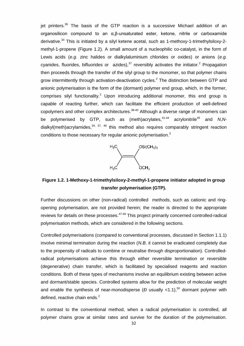
derivative.34 This is initiated by a silyl ketene acetal, such as 1-methoxy-1-trimethylsiloxy-2-
methyl-1-propene (Figure 1.2). A small amount of a nucleophilic co-catalyst, in the form of
Lewis acids (e.g. zinc halides or dialkylaluminium chlorides or oxides) or anions (e.g.
cyanides, fluorides, bifluorides or azides),37 reversibly activates the initiator.2 Propagation
then proceeds through the transfer of the silyl group to the monomer, so that polymer chains
grow intermittently through activation-deactivation cycles.2 The distinction between GTP and
anionic polymerisation is the form of the (dormant) polymer end group, which, in the former,
comprises silyl functionality.2 Upon introducing additional monomer, this end group is
capable of reacting further, which can facilitate the efficient production of well-defined
copolymers and other complex architectures.38-40 Although a diverse range of monomers can
be polymerised by GTP, such as (meth)acrylates,41-44 acrylonitrile45 and N,N-
dialkyl(meth)acrylamides,34, 37, 46 this method also requires comparably stringent reaction
conditions to those necessary for regular anionic polymerisation.3
Figure 1.2. 1-Methoxy-1-trimethylsiloxy-2-methyl-1-propene initiator adopted in group
transfer polymerisation (GTP).
Further discussions on other (non-radical) controlled methods, such as cationic and ring-
opening polymerisation, are not provided herein; the reader is directed to the appropriate
reviews for details on these processes.47-49 This project primarily concerned controlled-radical
polymerisation methods, which are considered in the following sections.
Controlled polymerisations (compared to conventional processes, discussed in Section 1.1.1)
involve minimal termination during the reaction (N.B. it cannot be eradicated completely due
to the propensity of radicals to combine or neutralise through disproportionation). Controlled-
radical polymerisations achieve this through either reversible termination or reversible
(degenerative) chain transfer, which is facilitated by specialised reagents and reaction
conditions. Both of these types of mechanisms involve an equilibrium existing between active
and dormant/stable species. Controlled systems allow for the prediction of molecular weight
and enable the synthesis of near-monodisperse (Ð usually <1.1),50 dormant polymer with
defined, reactive chain ends.2
In contrast to the conventional method, when a radical polymerisation is controlled, all
polymer chains grow at similar rates and survive for the duration of the polymerisation.
33
Initiation is fast with respect to propagation and termination is suppressed, which ultimately
ensures narrow dispersity. Specialised reagents enable the reversible deactivation of
propagating radicals, rendering most polymer chains dormant, whilst only a low
concentration of active species are present at any time. Thus, rapid equilibration between
active and dormant species provides all chains an equal chance of growing, albeit
intermittently. These conditions allow the molecular weight to increase linearly with monomer
conversion, whereas conventional, uncontrolled systems afford high molecular weight
polymer in the initial stages.11 This is adequately demonstrated previously in Figure 1.1,
alongside the trends for step-growth and uncontrolled chain polymerisations.
Those techniques which impart controlled character to a radical system include atom transfer
radical polymerisation (ATRP), nitroxide-mediated radical polymerisation (NMP) and RAFT
polymerisation. NMP and ATRP achieve control by reversible termination (or deactivation),51
where the growing polymer chain interacts with the metal halide of a complex (ATRP),52 or an
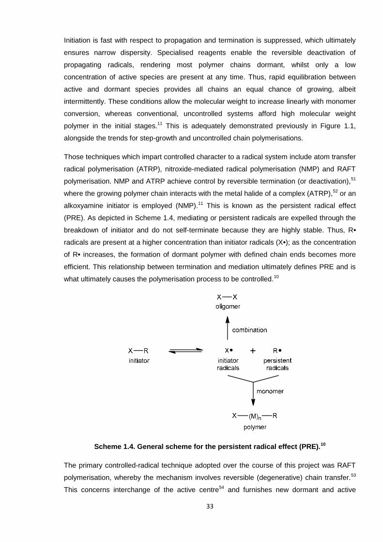
alkoxyamine initiator is employed (NMP).11 This is known as the persistent radical effect
(PRE). As depicted in Scheme 1.4, mediating or persistent radicals are expelled through the
breakdown of initiator and do not self-terminate because they are highly stable. Thus, R•
radicals are present at a higher concentration than initiator radicals (X•); as the concentration
of R• increases, the formation of dormant polymer with defined chain ends becomes more
efficient. This relationship between termination and mediation ultimately defines PRE and is
what ultimately causes the polymerisation process to be controlled.10
Scheme 1.4. General scheme for the persistent radical effect (PRE).10
The primary controlled-radical technique adopted over the course of this project was RAFT
polymerisation, whereby the mechanism involves reversible (degenerative) chain transfer.53
This concerns interchange of the active centre54 and furnishes new dormant and active
34
species of the same relative reactivity to the originals.55 RAFT is discussed after briefly
defining NMP and ATRP, respectively.
1.1.2.1. General features of nitroxide-mediated radical polymerisation (NMP)
As is typical for a controlled polymerisation, the polymer molecular weight increases linearly
with monomer conversion in NMP. This means that all polymer chains are initiated at the
start of the reaction and subsequently grow at the same rate, where control is imparted by
the reversible termination of propagating radicals. It is also possible to deduce the theoretical
molecular weight by specifying the monomer:initiator ratio. Narrow molecular weight
distribution (low Ð) polymer can be afforded, but this is only achieveable if the initiation step
is more rapid than propagation, as is the case for controlled-radical methods in general.
The key reagents in NMP are nitroxides, or their alkylated derivatives, alkoxyamines, which
take the form of R• and act as initiators and mediators. They function by reversibly capping
growing polymer chains, therefore minimising the occurrence of termination.
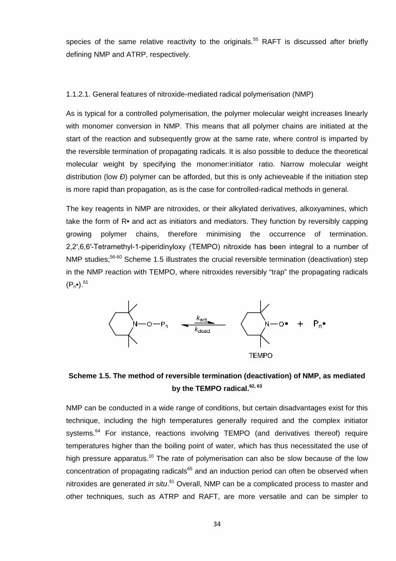
2,2′,6,6′-Tetramethyl-1-piperidinyloxy (TEMPO) nitroxide has been integral to a number of
NMP studies;56-60 Scheme 1.5 illustrates the crucial reversible termination (deactivation) step
in the NMP reaction with TEMPO, where nitroxides reversibly “trap” the propagating radicals
(Pn•).61
Scheme 1.5. The method of reversible termination (deactivation) of NMP, as mediated
by the TEMPO radical.62, 63
NMP can be conducted in a wide range of conditions, but certain disadvantages exist for this
technique, including the high temperatures generally required and the complex initiator
systems.64 For instance, reactions involving TEMPO (and derivatives thereof) require
temperatures higher than the boiling point of water, which has thus necessitated the use of
high pressure apparatus.10 The rate of polymerisation can also be slow because of the low
concentration of propagating radicals65 and an induction period can often be observed when
nitroxides are generated in situ.61 Overall, NMP can be a complicated process to master and
other techniques, such as ATRP and RAFT, are more versatile and can be simpler to
35
conduct (especially in case of the latter). These are considered, in turn, in the succeeding
sections.
1.1.2.2. General features of atom transfer radical polymerisation (ATRP)
As for NMP, the polymer molecular weight increases linearly over time in ATRP reactions.
Again, this is the key feature and advantage of this polymerisation technique, along with the
narrow molecular weight distributions (low Ð values) which are attainable.
The distinguishing feature of ATRP is that it is a catalytic process; a transition metal catalyst
is present at typically 1000 ppm relative to the monomer.66 Copper (I) is the most versatile
metal for the complex, which directly influences the shift of the reaction equilibrium and the
exchange between active and dormant entities.50 Alkyl halides act as initiators, whereby the
halogen atom (commonly bromine or chlorine) is transferred to the catalyst, which
subsequently causes oxidation of the metal and free radicals to be formed. Termination can
take place, again through the regular routes of combination and disproportionation, but a
successful ATRP reaction only sees this occur with a minimal portion of polymer chains
(≤5 %),50 largely due to the persistent radical effect (PRE),67 as highlighted in Section 1.1.2.
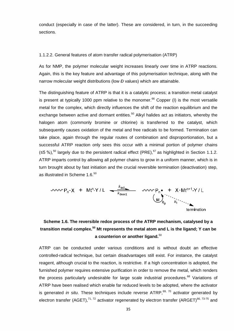
ATRP imparts control by allowing all polymer chains to grow in a uniform manner, which is in
turn brought about by fast initiation and the crucial reversible termination (deactivation) step,
as illustrated in Scheme 1.6.50
Scheme 1.6. The reversible redox process of the ATRP mechanism, catalysed by a
transition metal complex.50 Mt represents the metal atom and L is the ligand; Y can be
a counterion or another ligand.50
ATRP can be conducted under various conditions and is without doubt an effective
controlled-radical technique, but certain disadvantages still exist. For instance, the catalyst
reagent, although crucial to the reaction, is restrictive. If a high concentration is adopted, the
furnished polymer requires extensive purification in order to remove the metal, which renders
the process particularly undesirable for large scale industrial procedures.68 Variations of
ATRP have been realised which enable far reduced levels to be adopted, where the activator
is generated in situ. These techniques include reverse ATRP,69, 70 activator generated by
electron transfer (AGET),71, 72 activator regenerated by electron transfer (ARGET)66, 73-75 and
36
initiators for continuous activator generation (ICAR).76-78 Such processes employ the metal in
a higher oxidation state (at as low a level as <50 ppm), which thus becomes reduced.50 This
in turn simplifies the ATRP reaction and enhances its capabilities; conventional ATRP
systems require highly stringent conditions, where exclusion of moisture and air are
necessary in order to avoid premature oxidation of the metal.
ATRP is more versatile than NMP,11 as its various forms are able to furnish high molecular
weight polymers without compromising control over the polymerisation (i.e. obtaining low Ð
values).73 However, ATRP has itself been arguably overshadowed by the subsequent
discovery of reversible addition-fragmentation chain transfer polymerisation (RAFT).9 This
can be an even simpler method to synthesise predefined, monodisperse polymers and is
especially favourable because it does not require a metal catalyst.
1.1.2.3. Reversible addition-fragmentation chain transfer polymerisation (RAFT)
RAFT is a relatively straightforward method for synthesising a wide range of predefined
polymers, whereby such processes can be scaled-up for industrial application.79, 80 The
RAFT technique is now often preferred to NMP and ATRP because it is generally accepted
as the most convenient and versatile.19, 53, 81 RAFT was invented by CSIRO in the late 1990s9
and the technique has grown in popularity ever since. The key component to this free radical
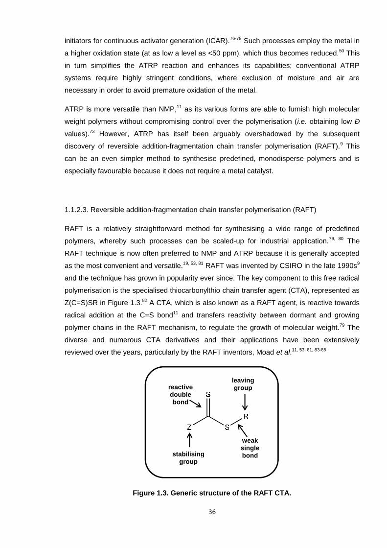
polymerisation is the specialised thiocarbonylthio chain transfer agent (CTA), represented as
Z(C=S)SR in Figure 1.3.82 A CTA, which is also known as a RAFT agent, is reactive towards
radical addition at the C=S bond11 and transfers reactivity between dormant and growing
polymer chains in the RAFT mechanism, to regulate the growth of molecular weight.79 The
diverse and numerous CTA derivatives and their applications have been extensively
reviewed over the years, particularly by the RAFT inventors, Moad et al.11, 53, 81, 83-85
Figure 1.3. Generic structure of the RAFT CTA.
weaksinglebond
leavinggroupreactive
doublebond
stabilisinggroup
37
1.1.2.3.1. The reversible addition-fragmentation chain transfer (RAFT) mechanism
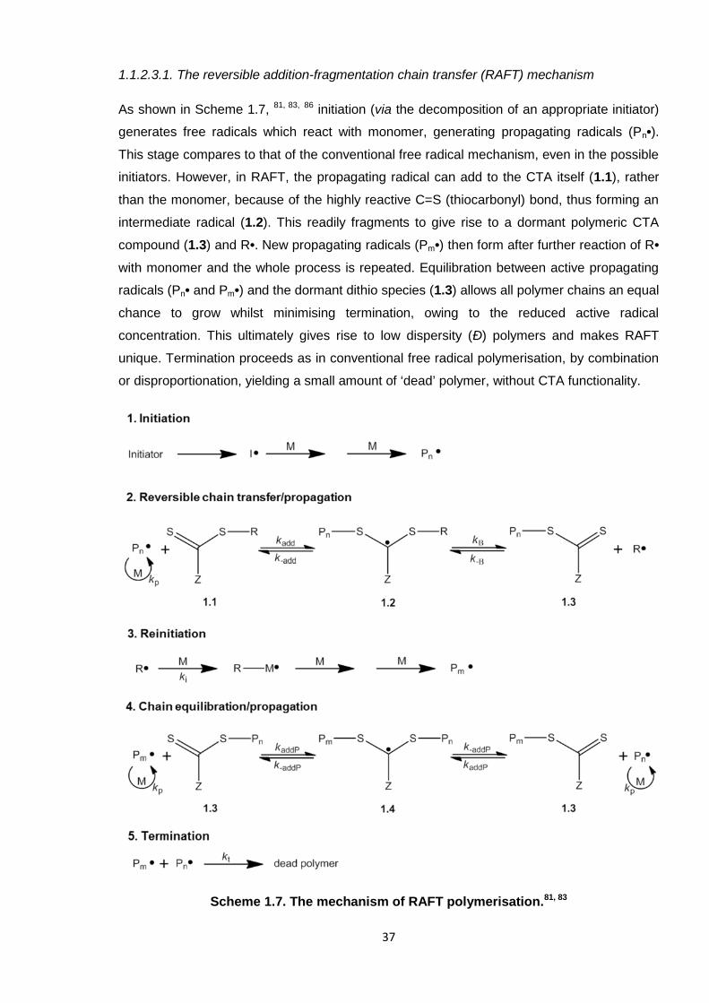
As shown in Scheme 1.7, 81, 83, 86 initiation (via the decomposition of an appropriate initiator)
generates free radicals which react with monomer, generating propagating radicals (Pn•).
This stage compares to that of the conventional free radical mechanism, even in the possible
initiators. However, in RAFT, the propagating radical can add to the CTA itself (1.1), rather
than the monomer, because of the highly reactive C=S (thiocarbonyl) bond, thus forming an
intermediate radical (1.2). This readily fragments to give rise to a dormant polymeric CTA
compound (1.3) and R•. New propagating radicals (Pm•) then form after further reaction of R•
with monomer and the whole process is repeated. Equilibration between active propagating
radicals (Pn• and Pm•) and the dormant dithio species (1.3) allows all polymer chains an equal
chance to grow whilst minimising termination, owing to the reduced active radical
concentration. This ultimately gives rise to low dispersity (Ð) polymers and makes RAFT
unique. Termination proceeds as in conventional free radical polymerisation, by combination
or disproportionation, yielding a small amount of ‘dead’ polymer, without CTA functionality.
Scheme 1.7. The mechanism of RAFT polymerisation.81, 83
38
Crucially, macroCTA (the dormant species, 1.3 in Scheme 1.7) is the major isolated product
and is capable of reacting further because of the CTA end group present on the polymer
chains.83 Hence the reason why RAFT polymerisation is a vital tool in the production of block
copolymers.84 If fragmentation is slow, it is possible for intermediate adducts 1.2 and 1.4 to
be consumed in side reactions and, if reinitiation is inefficient, retardation or inhibition can
occur. Optimal control over the reaction to avoid these instances relies heavily on the choice
of CTA, whereby the specific structure and functionality are vital.85
The effectiveness of the RAFT CTA can be qualitatively understood by the narrowness of the
polymer molecular weight distribution (low Ð value) and how closely the experimental
molecular weight (often expressed as Mnexp) correlates with the theoretical value (Mn
th, as
calculated through the monomer:CTA molar ratio). A more quantitative measure is to
determine the transfer coefficient of the reagent. The conventional Mayo equation,16 provided
in Section 1.1.1.1, is not applicable for such highly active mediators and so alternative, more
complex mathematics are required. One way to estimate the transfer coefficient is to
calculate the rates of consumption of the CTA and monomer. In terms of the RAFT
mechanism, the rate of consumption of the CTA depends on two transfer coefficients, Ctr
(= ktr / kp) and C-tr (= k-tr / ki), which respectively describe the reactivities of Pn• and R•. These
terms are incorporated within the following equation:87, 88
d[1.1] / d[M] ≈ Ctr x [1.1] / ([M] + Ctr[1.1] + C-tr[1.3]) (Eqn 1.5)
The numbers assigned in Equation 1.5 refer to the species in Scheme 1.7; ktr = kadd x [kβ /
(k-add + kβ)] and k-tr = k-β x [k-add / (k-add + kβ)].53 Such calculations can be applied to estimate
the transfer coefficient of the CTA and ultimately helps to define its behaviour in a RAFT
polymerisation reaction. These equations are based, however, on the assumption that the
adduct radical (1.2) is involved in no reaction other than fragmentation.53
1.1.2.3.2. Application of the RAFT CTA
With a generic structure denoted by Z(C=S)SR (see Figure 1.3), the Z group of the CTA
provides stability to the intermediate radicals and can be modified to alter the reactivity of the
molecule towards propagating radicals. The R group is required to be a good homolytic
leaving group, and R• must be capable of reinitiating polymerisation.11 Adapting the
functionality of either of these groups can affect the efficiency and outcome of the
polymerisation, depending on the monomer type. The roles of each group have been
reviewed by Chong et al. (R)87 and Chiefari et al. (Z),88 whereby an extensive account of the
general features of RAFT CTAs is provided by Keddie et al.85
39
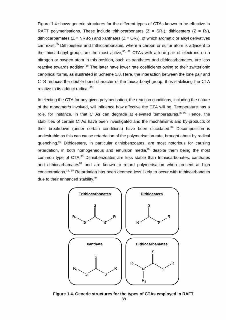
Figure 1.4 shows generic structures for the different types of CTAs known to be effective in
RAFT polymerisations. These include trithiocarbonates (Z = SR1), dithioesters (Z = R1),
dithiocarbamates (Z = NR1R2) and xanthates (Z = OR1), of which aromatic or alkyl derivatives
can exist.85 Dithioesters and trithiocarbonates, where a carbon or sulfur atom is adjacent to
the thiocarbonyl group, are the most active;85, 88 CTAs with a lone pair of electrons on a
nitrogen or oxygen atom in this position, such as xanthates and dithiocarbamates, are less
reactive towards addition.85 The latter have lower rate coefficients owing to their zwitterionic
canonical forms, as illustrated in Scheme 1.8. Here, the interaction between the lone pair and
C=S reduces the double bond character of the thiocarbonyl group, thus stabilising the CTA
relative to its adduct radical.85
In electing the CTA for any given polymerisation, the reaction conditions, including the nature
of the monomer/s involved, will influence how effective the CTA will be. Temperature has a
role, for instance, in that CTAs can degrade at elevated temperatures.89-92 Hence, the
stabilities of certain CTAs have been investigated and the mechanisms and by-products of
their breakdown (under certain conditions) have been elucidated.89 Decomposition is
undesirable as this can cause retardation of the polymerisation rate, brought about by radical
quenching.89 Dithioesters, in particular dithiobenzoates, are most notorious for causing
retardation, in both homogeneous and emulsion media,80 despite them being the most
common type of CTA.93 Dithiobenzoates are less stable than trithiocarbonates, xanthates
and dithiocarbamates89 and are known to retard polymerisation when present at high
concentrations.11, 85 Retardation has been deemed less likely to occur with trithiocarbonates
due to their enhanced stability.94
Figure 1.4. Generic structures for the types of CTAs employed in RAFT.
Xanthate Dithiocarbamates
DithioestersTrithiocarbonates
N
S
S
RR1
R2
40
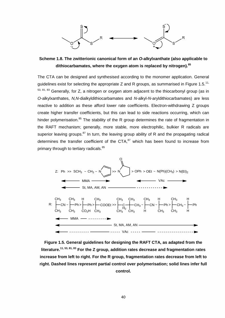
Scheme 1.8. The zwitterionic canonical form of an O-alkylxanthate (also applicable to
dithiocarbamates, where the oxygen atom is replaced by nitrogen).85
The CTA can be designed and synthesised according to the monomer application. General
guidelines exist for selecting the appropriate Z and R groups, as summarised in Figure 1.5.11,
53, 81, 83 Generally, for Z, a nitrogen or oxygen atom adjacent to the thiocarbonyl group (as in
O-alkylxanthates, N,N-dialkyldithiocarbamates and N-alkyl-N-aryldithiocarbamates) are less
reactive to addition as these afford lower rate coefficients. Electron-withdrawing Z groups
create higher transfer coefficients, but this can lead to side reactions occurring, which can
hinder polymerisation.85 The stability of the R group determines the rate of fragmentation in
the RAFT mechanism; generally, more stable, more electrophilic, bulkier R radicals are
superior leaving groups.87 In turn, the leaving group ability of R and the propagating radical
determines the transfer coefficient of the CTA,87 which has been found to increase from
primary through to tertiary radicals.85
Figure 1.5. General guidelines for designing the RAFT CTA, as adapted from the
literature.11, 53, 81, 83 For the Z group, addition rates decrease and fragmentation rates
increase from left to right. For the R group, fragmentation rates decrease from left to
right. Dashed lines represent partial control over polymerisation; solid lines infer full
control.
Ph SCH3 CH3 OPh OEt N(Ph)(CH3) N(Et)2N N
O
Z: >> ~ >~ >> > ~ >
R: CN
CH3
CH3
Ph
CH3
CH3
Ph
H
CO2H
COOEt
CH3
CH3
CN
CH3
H
Ph
H
CH3
CH3
CH3
CH3
Ph
H
H
CH2
CH3
CH3
CH3
CH3
CH3
~ >> >> > ~ ~ ~
MMA VAc
St, MA, AM, AN
MMA
St, MA, AM, AN
VAc
41
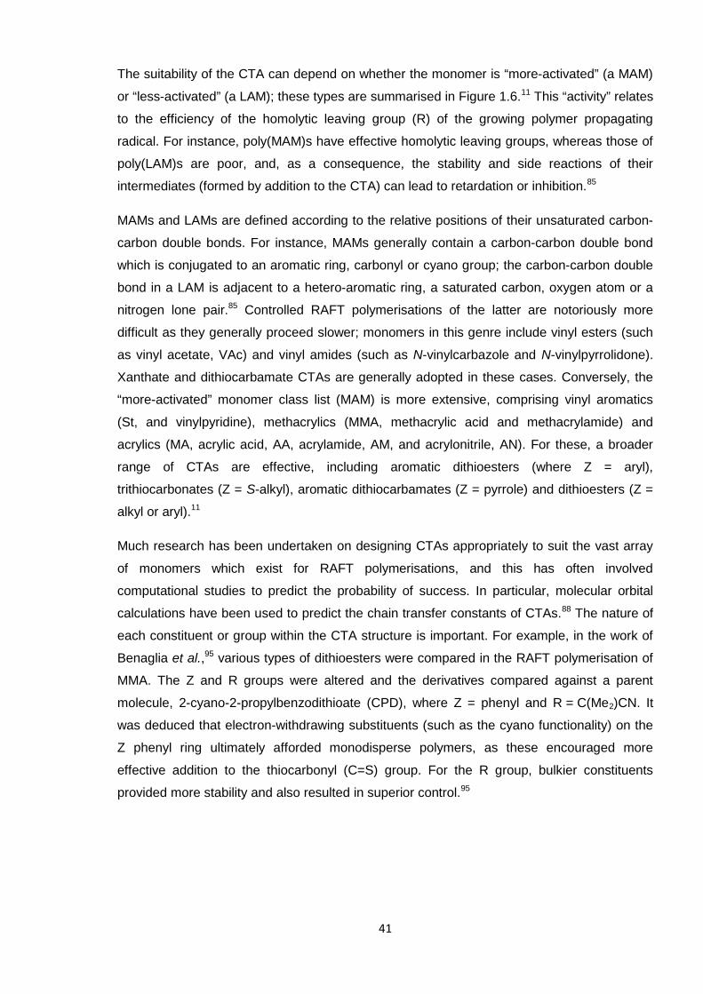
The suitability of the CTA can depend on whether the monomer is “more-activated” (a MAM)
or “less-activated” (a LAM); these types are summarised in Figure 1.6.11 This “activity” relates
to the efficiency of the homolytic leaving group (R) of the growing polymer propagating
radical. For instance, poly(MAM)s have effective homolytic leaving groups, whereas those of
poly(LAM)s are poor, and, as a consequence, the stability and side reactions of their
intermediates (formed by addition to the CTA) can lead to retardation or inhibition.85
MAMs and LAMs are defined according to the relative positions of their unsaturated carbon-
carbon double bonds. For instance, MAMs generally contain a carbon-carbon double bond
which is conjugated to an aromatic ring, carbonyl or cyano group; the carbon-carbon double
bond in a LAM is adjacent to a hetero-aromatic ring, a saturated carbon, oxygen atom or a
nitrogen lone pair.85 Controlled RAFT polymerisations of the latter are notoriously more
difficult as they generally proceed slower; monomers in this genre include vinyl esters (such
as vinyl acetate, VAc) and vinyl amides (such as N-vinylcarbazole and N-vinylpyrrolidone).
Xanthate and dithiocarbamate CTAs are generally adopted in these cases. Conversely, the
“more-activated” monomer class list (MAM) is more extensive, comprising vinyl aromatics
(St, and vinylpyridine), methacrylics (MMA, methacrylic acid and methacrylamide) and
acrylics (MA, acrylic acid, AA, acrylamide, AM, and acrylonitrile, AN). For these, a broader
range of CTAs are effective, including aromatic dithioesters (where Z = aryl),
trithiocarbonates (Z = S-alkyl), aromatic dithiocarbamates (Z = pyrrole) and dithioesters (Z =
alkyl or aryl).11
Much research has been undertaken on designing CTAs appropriately to suit the vast array
of monomers which exist for RAFT polymerisations, and this has often involved
computational studies to predict the probability of success. In particular, molecular orbital
calculations have been used to predict the chain transfer constants of CTAs.88 The nature of
each constituent or group within the CTA structure is important. For example, in the work of
Benaglia et al.,95 various types of dithioesters were compared in the RAFT polymerisation of
MMA. The Z and R groups were altered and the derivatives compared against a parent
molecule, 2-cyano-2-propylbenzodithioate (CPD), where Z = phenyl and R = C(Me2)CN. It
was deduced that electron-withdrawing substituents (such as the cyano functionality) on the
Z phenyl ring ultimately afforded monodisperse polymers, as these encouraged more
effective addition to the thiocarbonyl (C=S) group. For the R group, bulkier constituents
provided more stability and also resulted in superior control.95
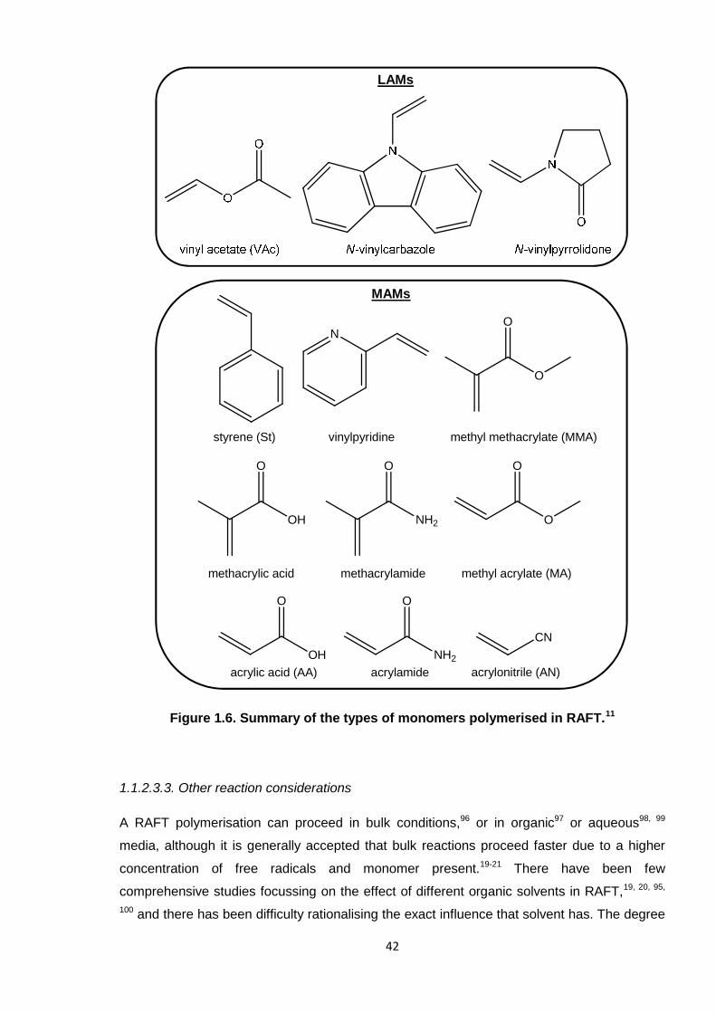
42
Figure 1.6. Summary of the types of monomers polymerised in RAFT.11
1.1.2.3.3. Other reaction considerations
A RAFT polymerisation can proceed in bulk conditions,96 or in organic97 or aqueous98, 99
media, although it is generally accepted that bulk reactions proceed faster due to a higher
concentration of free radicals and monomer present.19-21 There have been few
comprehensive studies focussing on the effect of different organic solvents in RAFT,19, 20, 95,
100 and there has been difficulty rationalising the exact influence that solvent has. The degree
N
O
O
OH
O
NH2
O
O
O
OH
O
NH2
O
CN
styrene (St) vinylpyridine methyl methacrylate (MMA)
methacrylic acid methacrylamide methyl acrylate (MA)
acrylic acid (AA) acrylamide acrylonitrile (AN)
MAMs
LAMs
43
of solubility of the medium has most often been the reason behind any change in
polymerisation profile. The ability of a solvent to dissolve the CTA95 or initiator100 has, for
instance, enabled higher conversions to be reached.95 Certain other characteristics of the
medium, such as the viscosity,100 aromaticity or polarity,20 have been deemed insignificant.
Interestingly, supercritical dioxide (scCO2) is also a viable solvent in RAFT (and ATRP)
reactions, as predominantly investigated by Howdle and co-workers.101-103 For instance,
RAFT-controlled dispersion polymerisation utilising scCO2 has enabled high purity block
copolymers of MMA and benzyl methacrylate (BzMA) or St to be furnished in a more efficient
manner than in an emulsion system.101 Here, ‘efficiency’ relates to the ratio of block
copolymer formed to residual homopolymer impurities (i.e. ‘dead’ chains without CTA
functionality, resulting from termination). More efficient copolymerisations yield higher purity
copolymer. scCO2 was so effective because it plasticised the PMMA, expanding the particles
and encouraging better diffusion (than a water medium would enable). By simply releasing
the pressure, it was also easier to separate the polymer and continuous phases, compared
to the more elaborate process of high-temperature drying.101 Similar conclusions have been
met for a wide range of other monomer/polymer combinations in RAFT.102 Additional benefits
of scCO2 include that it is readily available, chemically inert and inexpensive, and it can be an
environmentally friendly alternative to otherwise harmful solvents, hence it can be applied in
the diverse area of materials processing.104 The effects of solvent in RAFT are also
discussed within Chapter 3.
The temperature of a RAFT polymerisation is generally understood to be influential in much
the same way as for a conventional free radical reaction. Specific investigations into the
effects of temperature in RAFT polymerisation have concluded that, generally, faster rates of
polymerisation result from higher temperatures and often afford higher monomer
conversions.95, 105-108 Raising the temperature reduces the half-life (t1/2) of the initiator and
results in the more rapid production of free radicals, as expected.3 Higher temperatures,
however, can compromise the degree of control and cause broader molecular weight
distributions.90, 108, 109 Optimising the temperature is challenging and conditions are chosen
depending on the properties of the reagents employed. The CTA can be particularly
temperature-sensitive and can decompose at elevated temperatures (depending on its
nature), thus hindering the polymerisation mechanism.89-92 Given such difficulties, it is not
surprising that efforts are being made to achieve controlled polymerisation at lower
temperatures, which would certainly be economically advantageous in industrial
applications.110, 111
Less attention has been paid to the effect of pressure on RAFT polymerisations, but this is
nevertheless another experimental factor.112 Rzayev et al. have introduced polymer chemists
44
to high-pressure RAFT systems,113, 114 where the group was able to control the
polymerisation of methyl ethacrylate and other sterically-hindered α-substituted acrylates by
at five kbar pressure.114 Similarly, linear polymers of MMA were synthesised under
comparable conditions using 2-cyano-2-propylbenzodithioate (CPD) CTA, achieving
molecular weights of up to 1.25 million g/mol and retaining low dispersity (Ð <1.2).113 The
justification for adopting such high pressure conditions is usually to enhance the rates of
otherwise slow reactions and to obtain higher degrees of polymerisation, which would not
necessarily be achieved by simply raising the temperature. Crucially, such processes would
be more applicable in appropriately equipped industrial laboratories. The aforementioned
application of scCO2 in RAFT is an additional example of high pressure polymerisation
systems.101-103
1.1.2.3.4. General features of RAFT polymerisation
In summary, RAFT can be a very efficient method for producing low dispersit, predefined
polymer, once the technique has been mastered. After tackling the various factors, and the
appropriate CTAs have been designed, it is possible to predetermine the molecular weights
in the synthesis of a diverse range of polymers.
The CTA is vital to the RAFT reaction, where [in the Z(C=S)SR structure] the Z group
determines radical stability and R• reinitiates polymerisation. In the mechanism, equilibration
between active and dormant chains suppresses termination and provides all polymer chains
an equal chance to grow. An efficient process results in narrow molecular weight distributions
(low Ð values). The resulting isolated macroCTA polymer is able to react further, which
allows for the synthesis of copolymers.
Overall, RAFT can be conducted in a variety of reaction media, including water. As industrial
processes can still adopt organic solvents, the possibility of more environmentally friendly
aqueous systems render this a viable alternative. The absence of complex reagents (or
metals) renders RAFT a potentially more straightforward polymerisation method (versus
NMP and ATRP). RAFT was the principal controlled-radical polymerisation of choice
throughout this research in the novel syntheses of predefined poly(2-chloro-1,3-butadiene)
(PCB).
1.2. Cross-linking
A cross-linked polymer is defined as one where the polymer chains are linked together
forming a network system, as illustrated in Figure 1.7.1 In industry, terms such as
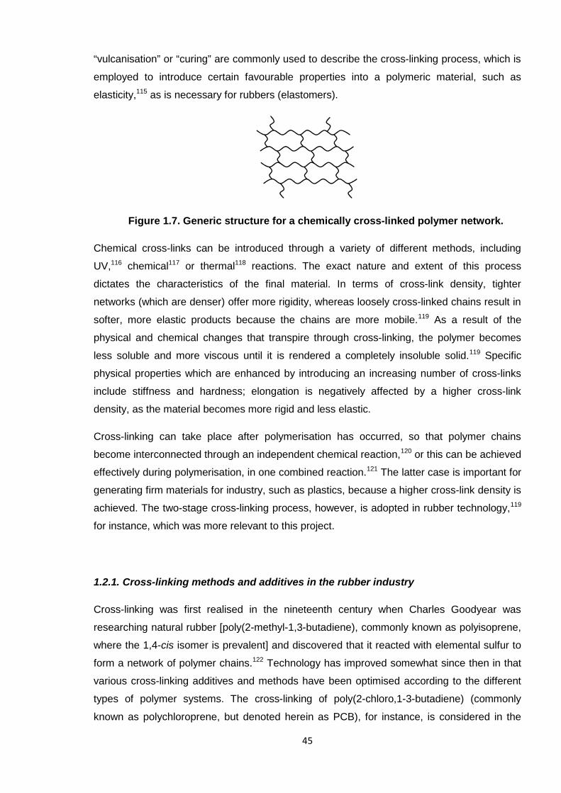
45
“vulcanisation” or “curing” are commonly used to describe the cross-linking process, which is
employed to introduce certain favourable properties into a polymeric material, such as
elasticity,115 as is necessary for rubbers (elastomers).
Figure 1.7. Generic structure for a chemically cross-linked polymer network.
Chemical cross-links can be introduced through a variety of different methods, including
UV,116 chemical117 or thermal118 reactions. The exact nature and extent of this process
dictates the characteristics of the final material. In terms of cross-link density, tighter
networks (which are denser) offer more rigidity, whereas loosely cross-linked chains result in
softer, more elastic products because the chains are more mobile.119 As a result of the
physical and chemical changes that transpire through cross-linking, the polymer becomes
less soluble and more viscous until it is rendered a completely insoluble solid.119 Specific
physical properties which are enhanced by introducing an increasing number of cross-links
include stiffness and hardness; elongation is negatively affected by a higher cross-link
density, as the material becomes more rigid and less elastic.
Cross-linking can take place after polymerisation has occurred, so that polymer chains
become interconnected through an independent chemical reaction,120 or this can be achieved
effectively during polymerisation, in one combined reaction.121 The latter case is important for
generating firm materials for industry, such as plastics, because a higher cross-link density is
achieved. The two-stage cross-linking process, however, is adopted in rubber technology,119
for instance, which was more relevant to this project.
1.2.1. Cross-linking methods and additives in the rubber industry
Cross-linking was first realised in the nineteenth century when Charles Goodyear was
researching natural rubber [poly(2-methyl-1,3-butadiene), commonly known as polyisoprene,
where the 1,4-cis isomer is prevalent] and discovered that it reacted with elemental sulfur to
form a network of polymer chains.122 Technology has improved somewhat since then in that
various cross-linking additives and methods have been optimised according to the different
types of polymer systems. The cross-linking of poly(2-chloro,1-3-butadiene) (commonly
known as polychloroprene, but denoted herein as PCB), for instance, is considered in the
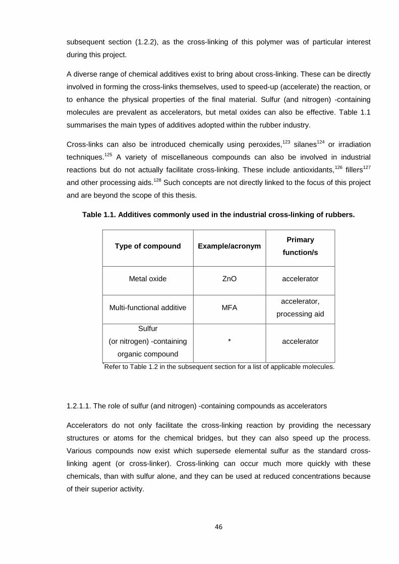
46
subsequent section (1.2.2), as the cross-linking of this polymer was of particular interest
during this project.
A diverse range of chemical additives exist to bring about cross-linking. These can be directly
involved in forming the cross-links themselves, used to speed-up (accelerate) the reaction, or
to enhance the physical properties of the final material. Sulfur (and nitrogen) -containing
molecules are prevalent as accelerators, but metal oxides can also be effective. Table 1.1
summarises the main types of additives adopted within the rubber industry.
Cross-links can also be introduced chemically using peroxides,123 silanes124 or irradiation
techniques.125 A variety of miscellaneous compounds can also be involved in industrial
reactions but do not actually facilitate cross-linking. These include antioxidants,126 fillers127
and other processing aids.128 Such concepts are not directly linked to the focus of this project
and are beyond the scope of this thesis.
Table 1.1. Additives commonly used in the industrial cross-linking of rubbers.
Type of compound Example/acronymPrimary
function/s
Metal oxide ZnO accelerator
Multi-functional additive MFAaccelerator,
processing aid
Sulfur
(or nitrogen) -containing
organic compound
* accelerator
*Refer to Table 1.2 in the subsequent section for a list of applicable molecules.
1.2.1.1. The role of sulfur (and nitrogen) -containing compounds as accelerators
Accelerators do not only facilitate the cross-linking reaction by providing the necessary
structures or atoms for the chemical bridges, but they can also speed up the process.
Various compounds now exist which supersede elemental sulfur as the standard cross-
linking agent (or cross-linker). Cross-linking can occur much more quickly with these
chemicals, than with sulfur alone, and they can be used at reduced concentrations because
of their superior activity.
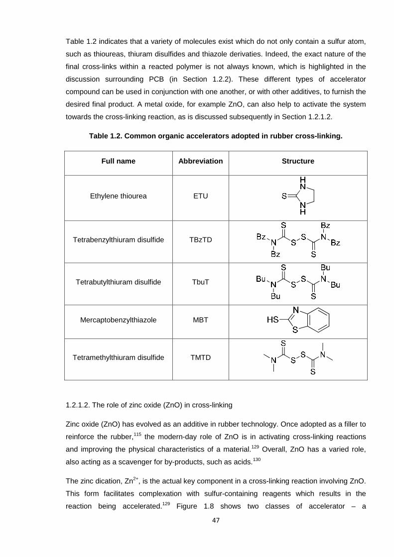
47
Table 1.2 indicates that a variety of molecules exist which do not only contain a sulfur atom,
such as thioureas, thiuram disulfides and thiazole derivaties. Indeed, the exact nature of the
final cross-links within a reacted polymer is not always known, which is highlighted in the
discussion surrounding PCB (in Section 1.2.2). These different types of accelerator
compound can be used in conjunction with one another, or with other additives, to furnish the
desired final product. A metal oxide, for example ZnO, can also help to activate the system
towards the cross-linking reaction, as is discussed subsequently in Section 1.2.1.2.
Table 1.2. Common organic accelerators adopted in rubber cross-linking.
Full name Abbreviation Structure
Ethylene thiourea ETU
Tetrabenzylthiuram disulfide TBzTD
Tetrabutylthiuram disulfide TbuT
Mercaptobenzylthiazole MBT
Tetramethylthiuram disulfide TMTD
1.2.1.2. The role of zinc oxide (ZnO) in cross-linking
Zinc oxide (ZnO) has evolved as an additive in rubber technology. Once adopted as a filler to
reinforce the rubber,115 the modern-day role of ZnO is in activating cross-linking reactions
and improving the physical characteristics of a material.129 Overall, ZnO has a varied role,
also acting as a scavenger for by-products, such as acids.130
The zinc dication, Zn2+, is the actual key component in a cross-linking reaction involving ZnO.
This form facilitates complexation with sulfur-containing reagents which results in the
reaction being accelerated.129 Figure 1.8 shows two classes of accelerator – a
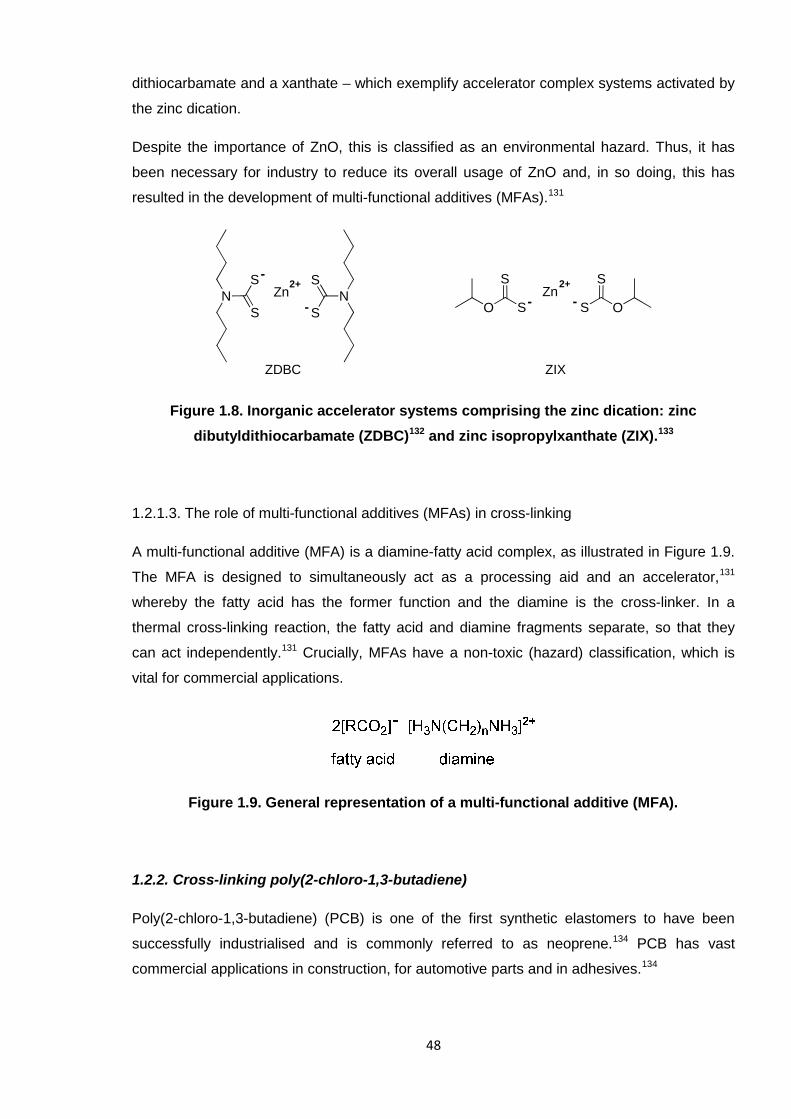
48
dithiocarbamate and a xanthate – which exemplify accelerator complex systems activated by
the zinc dication.
Despite the importance of ZnO, this is classified as an environmental hazard. Thus, it has
been necessary for industry to reduce its overall usage of ZnO and, in so doing, this has
resulted in the development of multi-functional additives (MFAs).131
Figure 1.8. Inorganic accelerator systems comprising the zinc dication: zinc
dibutyldithiocarbamate (ZDBC)132 and zinc isopropylxanthate (ZIX).133
1.2.1.3. The role of multi-functional additives (MFAs) in cross-linking
A multi-functional additive (MFA) is a diamine-fatty acid complex, as illustrated in Figure 1.9.
The MFA is designed to simultaneously act as a processing aid and an accelerator,131
whereby the fatty acid has the former function and the diamine is the cross-linker. In a
thermal cross-linking reaction, the fatty acid and diamine fragments separate, so that they
can act independently.131 Crucially, MFAs have a non-toxic (hazard) classification, which is
vital for commercial applications.
Figure 1.9. General representation of a multi-functional additive (MFA).
1.2.2. Cross-linking poly(2-chloro-1,3-butadiene)
Poly(2-chloro-1,3-butadiene) (PCB) is one of the first synthetic elastomers to have been
successfully industrialised and is commonly referred to as neoprene.134 PCB has vast
commercial applications in construction, for automotive parts and in adhesives.134
NS
SN
S
S
ZnO S
S
OS
SZn
ZDBC ZIX
- --
-2+2+
49
The wide-ranging uses of PCB are the result of excellent chemical and physical properties of
this material. In particular, the rubber is very durable where it can be exposed to deterioration
by a range of environmental factors;134 PCB has good chemical, oxidation, temperature and
ozone resistance.115 Overall, these attributes make this a functional material which can
operate under variable conditions. PCB is also relatively inexpensive, making it even more
attractive for the industries.
The cross-linking of PCB was studied as part of the industrial component of this project and
is introduced herein. Subsequently, the experimental results and discussion for this particular
element of work are provided in Chapter 4.
PCB consists of four possible isomers, as shown in Figure 1.10. The commercial rubber
comprises mainly the 1,4-trans configuration (78 – 96 %), as assigned through FTIR
studies.135 Thereafter, the other isomers present are fairly minor; the 1,4-cis isomer exists
within 4 – 18 %, followed by the 3,4- (0.2 – 2 %) and the 1,2- (0.3 – 2 %).135 The presence of
these four isomers can make the accurate analysis of this polymer and related reactions
difficult (as discussed further in Section 3.2.3). For the remainder of this review section, the
PCB rubber discussed pertains to the overall composition of the material, with each isomer
defined only where appropriate.
Figure 1.10. The four isomers of poly(2-chloro-1,3-butadiene) (PCB).
1.2.2.1. Typical PCB cross-linking additives
The PCB cross-linking reaction has always been topical because this polymer behaves
differently to others,136 such as 1,4-cis-polyisoprene (the main constituent of natural
rubber).134 As Figure 1.11 shows, the primary difference between 1,4-cis-polyisoprene and
50
1,4-trans-PCB (aside from their cis/trans configurations) is the tertiary chlorine atom of PCB,
whereas polyisoprene contains a methyl group in this position. The electronegative chlorine
atom prevents regular sulfur cross-linking occurring by essentially deactivating the carbon-
carbon double bond in the backbone of the polymer.136 It is well-known that this dissimilarity
causes rearrangement of the chlorine in the 1,2-PCB isomer (as summarised in Scheme 1.9)
and this is generally accepted as the initial step of the cross-linking mechanism for this
polymer, irrespective of the reaction conditions.137-141
Figure 1.11. Comparison of the structures of 1,4-cis-polyisoprene and 1,4-trans-PCB.
Scheme 1.9. Allylic rearrangement of the chlorine atom in 1,2-PCB.
The main reagents in an industrial PCB cross-linking reaction are ZnO and ethylene thiourea
(ETU or 2-imidazolidinethione), either on their own, or in combination with each other.
Despite these molecules being prevalent for well over 50 years, the specific mechanisms of
the reactions still have not been fully ascertained. The structure of ETU is shown in Scheme
1.10 (1.5), which possesses a tautomeric form, mercaptoimidazoline (1.6). This second
structure (1.6) accounts for approximately 58 % of the total compound.142
Scheme 1.10. The tautomeric forms of ethylene thiourea (ETU, 1.5).
The intention of the cross-linking studies undertaken during this project was to aid in the full
elucidation of the cross-linking mechanism of PCB. This contributed to a larger Europe-wide
51
project (“SafeRubber”)143 whose objective was to replace ETU as the cross-linker for PCB,
due to the associated health hazards. ETU is under scrutiny mainly because of its potential
carcinogenicity.144-147 Considerable animal testing has been performed with ETU, which has
correlated possible thyroid problems148-150 and the potential danger to unborn foetuses151 with
humans who came in contact with the substance.
Hence, it was vital to know exactly how ETU functioned during the cross-linking of PCB, so
that a safer, non-toxic replacement could be sought. This alternative should react in the
same way as ETU so as to yield properties in the rubber which are comparable to, or an
improvement on, the predecessor system. The cross-linking of PCB was thus researched
and complemented the work of K. Berry at Robinson Brothers Ltd. (RBL), West Bromwich.152
Investigations have been undertaken elsewhere, attempting to elucidate the PCB cross-
linking mechanism, with ETU alone or in combination with metal oxides. These studies are
discussed in the following sub-sections, as appropriate.
1.2.2.2. PCB cross-linking theories – ZnO alone
As mentioned in Section 1.2.1.2, one of the vital roles of a metal oxide is to activate cross-
linking via the Zn2+ dication. ZnO, and magnesium oxide (MgO), are also able to absorb
acids which are evolved during a reaction (such as hydrochloric acid, HCl, a consequence of
the chlorine atom of PCB). Metal chlorides can thus eventually form and these in turn help to
facilitate activation. It has been found that MgO does not act in this way as efficiently as ZnO
and adopting MgO can negatively affect the degree of cross-linking in the final material.153, 154
This is due to the MgO-sulfur intermediate complexes being less able to progress to cross-
linking because MgO has a higher affinity for sulfur (than ZnO); sulfur-containing compounds
are less capable of forming cross-links when MgO is present in the reaction.153, 154 Hence,
ZnO generally features more prominently in reports and is more relevant here, to PCB.
ZnO is capable of cross-linking PCB without any additional reagents present, which is an
unusual characteristic for a metal oxide, whose main responsibility is to accelerate the
reaction. The generally accepted initial step of the ZnO mechanism is allylic rearrangement
of the tertiary chlorine atom of 1,2-PCB.137-141 Hereafter, a number of different views are
taken. The most prominent theories for the cross-linking of PCB by ZnO alone propose
cationic mechanisms. For instance, Vukov155 used model compounds to propose the concept
of diene formation, which would act as a catalyst. Similarly, Desai137 proposed a three-stage
mechanism, which comprised the generation of a carbocation. This mechanism is shown in
Scheme 1.11, with the initial isomerisation step omitted as this was shown previously
(Scheme 1.9). Crucially, this theory involved zinc chloride (ZnCl2) in place of ZnO. To note,
52
Desai postulates that ZnCl3- forms during this reaction (as illustrated in the scheme), but the
author does not believe that it is possible for this species to chemically exist.
Scheme 1.11. The cationic mechanism for cross-linking PCB, as facilitated by ZnO,
proposed by Desai et al.137
H2C C
CHH2C
Cl
ZnCl2
H2C C
CHH2CZnCl3
H2CC
HC
H2C Cl
H2C
CCH
H2C
CH2
CC
CH2
Cl
ZnCl2 HCl
½ ZnO
1½ ZnCl2 ½ H2O
H2C C
CHH2C
ZnCl3
CH2
CC
CH2
Cl
rearranged 1,2-isomer
carbocation
- +
-
+
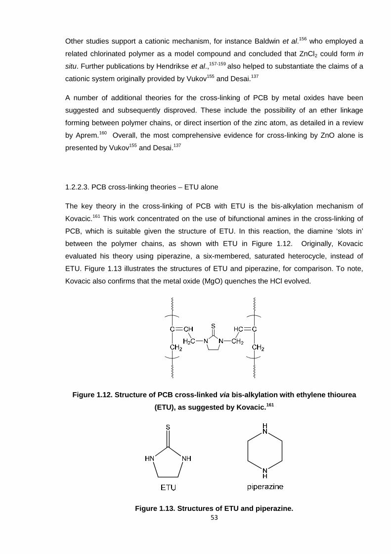
53
Other studies support a cationic mechanism, for instance Baldwin et al.156 who employed a
related chlorinated polymer as a model compound and concluded that ZnCl2 could form in
situ. Further publications by Hendrikse et al.,157-159 also helped to substantiate the claims of a
cationic system originally provided by Vukov155 and Desai.137
A number of additional theories for the cross-linking of PCB by metal oxides have been
suggested and subsequently disproved. These include the possibility of an ether linkage
forming between polymer chains, or direct insertion of the zinc atom, as detailed in a review
by Aprem.160 Overall, the most comprehensive evidence for cross-linking by ZnO alone is
presented by Vukov155 and Desai.137
1.2.2.3. PCB cross-linking theories – ETU alone
The key theory in the cross-linking of PCB with ETU is the bis-alkylation mechanism of
Kovacic.161 This work concentrated on the use of bifunctional amines in the cross-linking of
PCB, which is suitable given the structure of ETU. In this reaction, the diamine ‘slots in’
between the polymer chains, as shown with ETU in Figure 1.12. Originally, Kovacic
evaluated his theory using piperazine, a six-membered, saturated heterocycle, instead of
ETU. Figure 1.13 illustrates the structures of ETU and piperazine, for comparison. To note,
Kovacic also confirms that the metal oxide (MgO) quenches the HCl evolved.
Figure 1.12. Structure of PCB cross-linked via bis-alkylation with ethylene thiourea
(ETU), as suggested by Kovacic.161
Figure 1.13. Structures of ETU and piperazine.
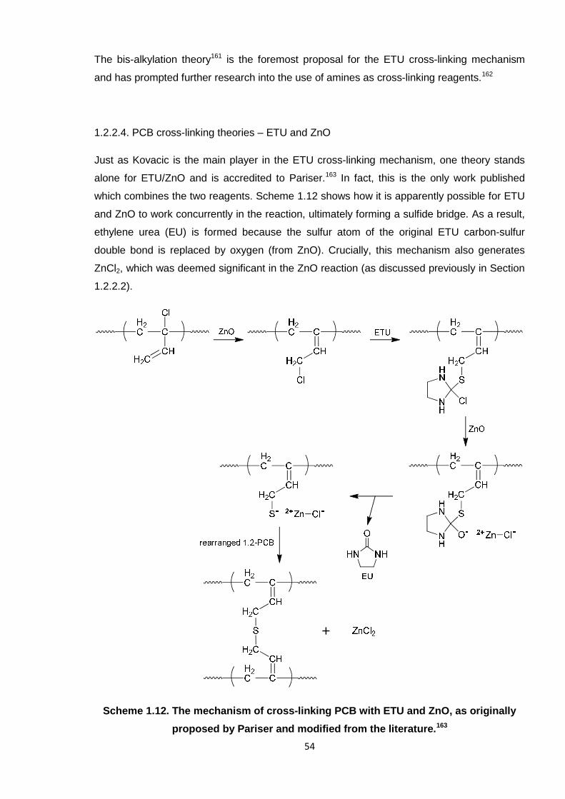
54
The bis-alkylation theory161 is the foremost proposal for the ETU cross-linking mechanism
and has prompted further research into the use of amines as cross-linking reagents.162
1.2.2.4. PCB cross-linking theories – ETU and ZnO
Just as Kovacic is the main player in the ETU cross-linking mechanism, one theory stands
alone for ETU/ZnO and is accredited to Pariser.163 In fact, this is the only work published
which combines the two reagents. Scheme 1.12 shows how it is apparently possible for ETU
and ZnO to work concurrently in the reaction, ultimately forming a sulfide bridge. As a result,
ethylene urea (EU) is formed because the sulfur atom of the original ETU carbon-sulfur
double bond is replaced by oxygen (from ZnO). Crucially, this mechanism also generates
ZnCl2, which was deemed significant in the ZnO reaction (as discussed previously in Section
1.2.2.2).
Scheme 1.12. The mechanism of cross-linking PCB with ETU and ZnO, as originally
proposed by Pariser and modified from the literature.163
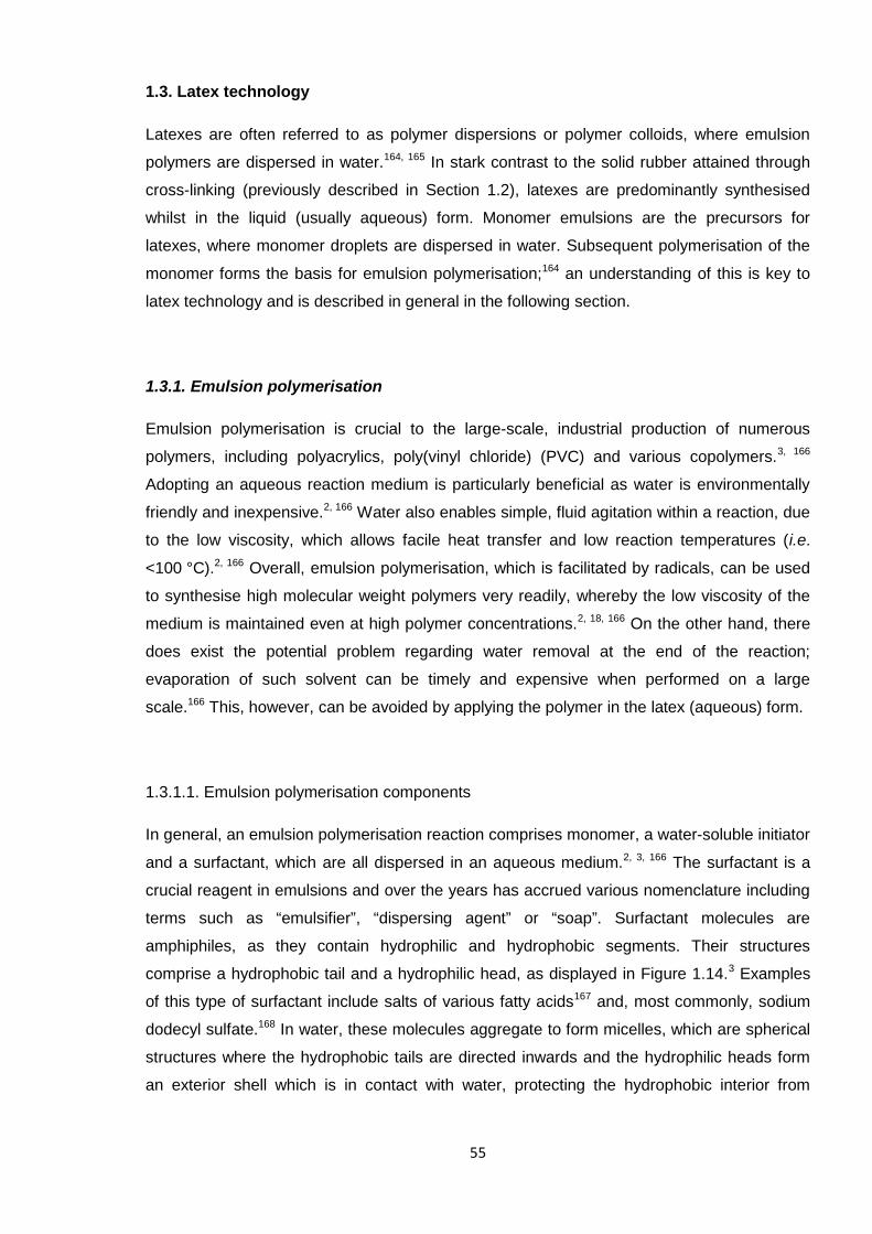
55
1.3. Latex technology
Latexes are often referred to as polymer dispersions or polymer colloids, where emulsion
polymers are dispersed in water.164, 165 In stark contrast to the solid rubber attained through
cross-linking (previously described in Section 1.2), latexes are predominantly synthesised
whilst in the liquid (usually aqueous) form. Monomer emulsions are the precursors for
latexes, where monomer droplets are dispersed in water. Subsequent polymerisation of the
monomer forms the basis for emulsion polymerisation;164 an understanding of this is key to
latex technology and is described in general in the following section.
1.3.1. Emulsion polymerisation
Emulsion polymerisation is crucial to the large-scale, industrial production of numerous
polymers, including polyacrylics, poly(vinyl chloride) (PVC) and various copolymers.3, 166
Adopting an aqueous reaction medium is particularly beneficial as water is environmentally
friendly and inexpensive.2, 166 Water also enables simple, fluid agitation within a reaction, due
to the low viscosity, which allows facile heat transfer and low reaction temperatures (i.e.
<100 °C).2, 166 Overall, emulsion polymerisation, which is facilitated by radicals, can be used
to synthesise high molecular weight polymers very readily, whereby the low viscosity of the
medium is maintained even at high polymer concentrations.2, 18, 166 On the other hand, there
does exist the potential problem regarding water removal at the end of the reaction;
evaporation of such solvent can be timely and expensive when performed on a large
scale.166 This, however, can be avoided by applying the polymer in the latex (aqueous) form.
1.3.1.1. Emulsion polymerisation components
In general, an emulsion polymerisation reaction comprises monomer, a water-soluble initiator
and a surfactant, which are all dispersed in an aqueous medium.2, 3, 166 The surfactant is a
crucial reagent in emulsions and over the years has accrued various nomenclature including
terms such as “emulsifier”, “dispersing agent” or “soap”. Surfactant molecules are
amphiphiles, as they contain hydrophilic and hydrophobic segments. Their structures
comprise a hydrophobic tail and a hydrophilic head, as displayed in Figure 1.14.3 Examples
of this type of surfactant include salts of various fatty acids167 and, most commonly, sodium
dodecyl sulfate.168 In water, these molecules aggregate to form micelles, which are spherical
structures where the hydrophobic tails are directed inwards and the hydrophilic heads form
an exterior shell which is in contact with water, protecting the hydrophobic interior from
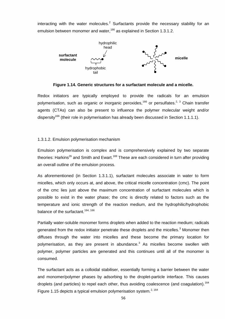
56
interacting with the water molecules.2 Surfactants provide the necessary stability for an
emulsion between monomer and water,166 as explained in Section 1.3.1.2.
Figure 1.14. Generic structures for a surfactant molecule and a micelle.
Redox initiators are typically employed to provide the radicals for an emulsion
polymerisation, such as organic or inorganic peroxides,166 or persulfates.2, 3 Chain transfer
agents (CTAs) can also be present to influence the polymer molecular weight and/or
dispersity166 (their role in polymerisation has already been discussed in Section 1.1.1.1).
1.3.1.2. Emulsion polymerisation mechanism
Emulsion polymerisation is complex and is comprehensively explained by two separate
theories: Harkins26 and Smith and Ewart.169 These are each considered in turn after providing
an overall outline of the emulsion process.
As aforementioned (in Section 1.3.1.1), surfactant molecules associate in water to form
micelles, which only occurs at, and above, the critical micelle concentration (cmc). The point
of the cmc lies just above the maximum concentration of surfactant molecules which is
possible to exist in the water phase; the cmc is directly related to factors such as the
temperature and ionic strength of the reaction medium, and the hydrophilic/hydrophobic
balance of the surfactant.164, 166
Partially water-soluble monomer forms droplets when added to the reaction medium; radicals
generated from the redox initiator penetrate these droplets and the micelles.3 Monomer then
diffuses through the water into micelles and these become the primary location for
polymerisation, as they are present in abundance.3 As micelles become swollen with
polymer, polymer particles are generated and this continues until all of the monomer is
consumed.
The surfactant acts as a colloidal stabiliser, essentially forming a barrier between the water
and monomer/polymer phases by adsorbing to the droplet-particle interface. This causes
droplets (and particles) to repel each other, thus avoiding coalescence (and coagulation).164
Figure 1.15 depicts a typical emulsion polymerisation system.2, 164
surfactantmolecule micelle
hydrophilichead
hydrophobictail

57
Figure 1.15. General representation of an emulsion polymerisation system, as adapted
from the literature.164
1.3.1.2.1. The Harkins theory
The Harkins theory of emulsion polymerisation26 is a qualitative view of the process and is
based on three defined intervals occurring during the reaction. As summarised in the
previous account (Section 1.3.1.2), radicals are firstly generated in the aqueous phase and
diffuse mostly into monomer-swollen micelles, which offer an overall larger surface area than
monomer droplets. Within the micelle, a polymer chain is initiated and growth continues as
monomer is continually stripped from droplets. As this reaction progresses, the micelle
transforms into a polymer particle, which is the primary location for polymerisation. This
58
defines the first interval of Harkins,26 which transpires over a very short period of time (up to
just 5 % monomer conversion), as the polymerisation rate is rapid.
The rate of the second interval of polymerisation is approximately constant. Here, polymer
particles remain saturated with monomer, which is continually diffusing from droplets. The
concentrations of the monomer in the aqueous phase and in the polymer particles are at a
thermodynamic equilibrium.
Interval three occurs after ~60 – 65 % conversion has been reached,2, 166 where monomer is
depleted and the droplets have disappeared. Thus, the concentration of monomer in the
polymer particle decreases because of this deficiency, which yields a reduced rate of
polymerisation. The reaction ceases when almost all of the monomer (~99 % conversion) is
consumed and the polymer particles are fully grown.
1.3.1.2.2. The Smith and Ewart theory
The Smith and Ewart theory is a quantitative explanation of the emulsion polymerisation
process and includes the derivation of kinetics equations.169 This was developed around the
same time (i.e. the late 1940s) and complements the discovery of Harkins.26
This theory also assumes that the monomer-containing micelle is penetrated by a radical
diffusing through water, whereby chain propagation is initiated. At this point, the radical is
active and growth will continue until another radical enters the micelle, where they are then
terminated by each other. Propagation is thus postponed until a third radical arrives to re-
initiate growth. This forms the basis of the Smith and Ewart theory, where only one radical
can be tolerated in a micelle at any one time. It can thus be imagined that it is a somewhat
‘start/stop’ process and the rate of the ‘on/off’ switching is determined by the number of
micelles present and the rate of radical generation. Furthermore, it can be seen that the
probability of a polymer chain growing in a micelle is 50:50, which gives rise to the primary
kinetics equation (Equation 1.6) for the rate of emulsion polymerisation:3
Rp = kp[M*][N* / 2] (Eqn 1.6)
Where kp = the propagation rate constant; M* = the concentration of monomer present in the
micelle; N* / 2 = the number of active micelles.
From this, it can be understood that the polymerisation rate is dependent on the
concentration of micelles, if the concentration of the initiator remains fixed. A larger number
of micelles present in the system will clearly enable more polymer particles to form. Thus,
given that micelles are aggregates of surfactant molecules, the concentration of the
59
surfactant should be increased in order to enhance the rate (without varying the initiator
concentration). Furthermore, the degree of polymerisation (Dp) is directly related to the
number of monomer molecules polymerised in a particle,2 which is also directly related to the
number of micelles and the surfactant initially employed. Therefore, the surfactant
concentration not only dictates the rate of polymerisation, but also the final polymer
molecular weight achieved. This undoubtedly reaffirms how crucial the role of the surfactant
is in emulsion polymerisation.
Variations of the rate equation provided (Equation 1.6) are present amongst the literature
and N can also be defined as the number of polymer particles per volume of water.2, 164
Given that polymer particles are generated within micelles, the concentrations of the two are
directly related. Hence, it is not surprising that all versions draw the same conclusion: the
surfactant concentration is fundamental in influencing the rate and molecular weight.169
Considering the theoretical aspects of emulsion polymerisation provided up to this point, the
practical aspects of latex formulation are now discussed, including the typical reaction
reagents and how latex films are practically obtained.
1.3.2. Latex formulation
A general discussion is provided herein concerning the various latex reagents which can
comprise a typical formulation. Thereafter, a standard technique adopted in obtaining rubber
latex films is explained followed by an introduction to tensile testing.
1.3.2.1. Formulations
Table 1.3 illustrates the various reagents which are employed in latex formulations; this is
edited from a report by Anderson164 and accompanied by specific references where
appropriate. This list represents a composition which includes the additives necessary for
polymerisation, such as monomer, initiator, etc, but it is also possible to formulate latexes
using pre-prepared polymer (i.e. where polymerisation is performed separately, beforehand).
In this latter case, only the relevant accelerators, antioxidants and various modifiers would be
required; this approach was specifically adopted in the experiments detailed in Chapter 5,
which is of a similar format to the studies by Rattanasom et al.170
Compounds acting as biocides or fungicides can also be incorporated into a latex (usually
post-polymerisation). These are especially important when the product is intended for use in
environments where microbes thrive, such as for exterior latex paints. Also, pigments or dyes
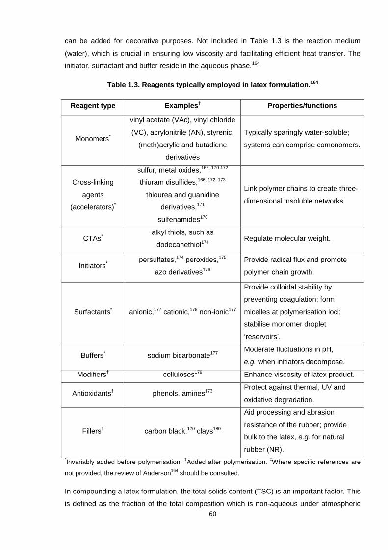
60
can be added for decorative purposes. Not included in Table 1.3 is the reaction medium
(water), which is crucial in ensuring low viscosity and facilitating efficient heat transfer. The
initiator, surfactant and buffer reside in the aqueous phase.164
Table 1.3. Reagents typically employed in latex formulation.164
Reagent type Examples‡ Properties/functions
Monomers*
vinyl acetate (VAc), vinyl chloride
(VC), acrylonitrile (AN), styrenic,
(meth)acrylic and butadiene
derivatives
Typically sparingly water-soluble;
systems can comprise comonomers.
Cross-linking
agents
(accelerators)*
sulfur, metal oxides,166, 170-172
thiuram disulfides,166, 172, 173
thiourea and guanidine
derivatives,171
sulfenamides170
Link polymer chains to create three-
dimensional insoluble networks.
CTAs*alkyl thiols, such as
dodecanethiol174Regulate molecular weight.
Initiators*persulfates,174 peroxides,175
azo derivatives176
Provide radical flux and promote
polymer chain growth.
Surfactants* anionic,177 cationic,178 non-ionic177
Provide colloidal stability by
preventing coagulation; form
micelles at polymerisation loci;
stabilise monomer droplet
‘reservoirs’.
Buffers* sodium bicarbonate177Moderate fluctuations in pH,
e.g. when initiators decompose.
Modifiers† celluloses179 Enhance viscosity of latex product.
Antioxidants† phenols, amines173Protect against thermal, UV and
oxidative degradation.
Fillers† carbon black,170 clays180
Aid processing and abrasion
resistance of the rubber; provide
bulk to the latex, e.g. for natural
rubber (NR).*Invariably added before polymerisation.
†Added after polymerisation.
‡Where specific references are
not provided, the review of Anderson164
should be consulted.
In compounding a latex formulation, the total solids content (TSC) is an important factor. This
is defined as the fraction of the total composition which is non-aqueous under atmospheric
61
conditions and is often expressed as a weight percentage (% w/w).171 Practically, this simply
represents the quantity of solid additives which are dispersed in the water phase. The TSC is
typically at least 40 %,165 but varies according to the (co)polymer being adopted and the final
latex application.115
Most of the technology for a latex formulation is similar to that in standard rubber
compounding; the main difference is simply that the reaction proceeds in water, so that the
final product is not a mass of solid rubber, but a soft, elastic material. The reagents employed
for cross-linking (as discussed in the section devoted to this topic, 1.2) are typically the same
and are determined by the base polymer.171 An identical cross-linking reaction occurs, which
is often activated by metal oxides, and more than one accelerator type can be present.170
Other noteworthy latex ingredients include antioxidants, which provide stability to the final
product. This is especially crucial given the thinness of latex films, in general, which expose a
larger surface area and are therefore more susceptible to degradation by the atmosphere
(UV, heat, etc).171 Fillers seem rather unusual, but are basic reagents employed primarily to
bulk out the latex formulation and to aid processing (therefore reducing large-scale
production costs). Kaolin clay is a common filler due to its fine particle size and was adopted
in these studies (see Chapter 5).171
1.3.2.2. Latex compounding
Formulating a latex, which is referred to as ‘compounding’ throughout the rubber industry
(irrespective of the state of the rubber), involves the mixing of the reagents (also termed
ingredients or additives) in the form of water dispersions.115 These are mostly water-insoluble
solids and so they are initially ground down (or milled) so that fine particles exist to be more
readily dispersed;165 fine particles are especially important when thin latex films are
intended.171 Additionally, a dispersing agent, such as sodium naphthalene formaldehyde
sulfonate, can be added to aid the incorporation of additives into the latex.165
After a polymer is synthesised via emulsion polymerisation, it remains within an aqueous
medium and additional ingredients intended for the final latex product are added to this within
a single (chemically unreactive) vessel. The reagent dispersions are shaken thoroughly
before being added dropwise to the main solution, which is set to stir slowly. It is important
that the latex formulation does not become stationary for a length of time, otherwise the solid
constituents are likely to settle, which will render the final films inhomogeneous.165
Overall, the compounding of latexes is a slow process which requires due care; any debris or
imperfections in the vessel can affect the outcome of the final film, such as in compromising
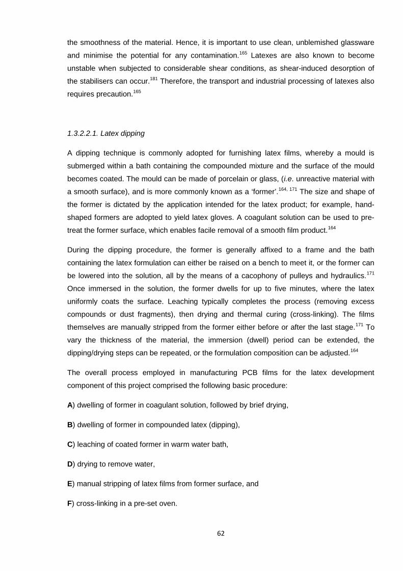
62
the smoothness of the material. Hence, it is important to use clean, unblemished glassware
and minimise the potential for any contamination.165 Latexes are also known to become
unstable when subjected to considerable shear conditions, as shear-induced desorption of
the stabilisers can occur.181 Therefore, the transport and industrial processing of latexes also
requires precaution.165
1.3.2.2.1. Latex dipping
A dipping technique is commonly adopted for furnishing latex films, whereby a mould is
submerged within a bath containing the compounded mixture and the surface of the mould
becomes coated. The mould can be made of porcelain or glass, (i.e. unreactive material with
a smooth surface), and is more commonly known as a ‘former’.164, 171 The size and shape of
the former is dictated by the application intended for the latex product; for example, hand-
shaped formers are adopted to yield latex gloves. A coagulant solution can be used to pre-
treat the former surface, which enables facile removal of a smooth film product.164
During the dipping procedure, the former is generally affixed to a frame and the bath
containing the latex formulation can either be raised on a bench to meet it, or the former can
be lowered into the solution, all by the means of a cacophony of pulleys and hydraulics.171
Once immersed in the solution, the former dwells for up to five minutes, where the latex
uniformly coats the surface. Leaching typically completes the process (removing excess
compounds or dust fragments), then drying and thermal curing (cross-linking). The films
themselves are manually stripped from the former either before or after the last stage.171 To
vary the thickness of the material, the immersion (dwell) period can be extended, the
dipping/drying steps can be repeated, or the formulation composition can be adjusted.164
The overall process employed in manufacturing PCB films for the latex development
component of this project comprised the following basic procedure:
A) dwelling of former in coagulant solution, followed by brief drying,
B) dwelling of former in compounded latex (dipping),
C) leaching of coated former in warm water bath,
D) drying to remove water,
E) manual stripping of latex films from former surface, and
F) cross-linking in a pre-set oven.
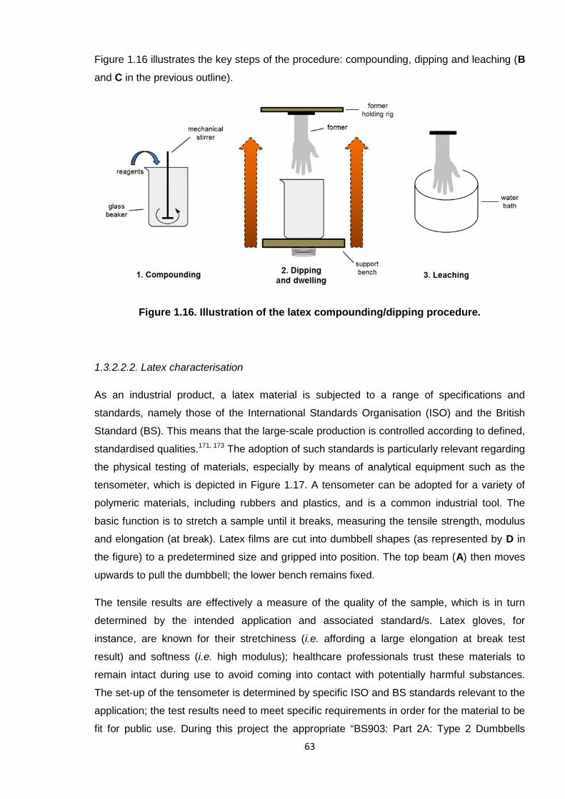
63
Figure 1.16 illustrates the key steps of the procedure: compounding, dipping and leaching (B
and C in the previous outline).
Figure 1.16. Illustration of the latex compounding/dipping procedure.
1.3.2.2.2. Latex characterisation
As an industrial product, a latex material is subjected to a range of specifications and
standards, namely those of the International Standards Organisation (ISO) and the British
Standard (BS). This means that the large-scale production is controlled according to defined,
standardised qualities.171, 173 The adoption of such standards is particularly relevant regarding
the physical testing of materials, especially by means of analytical equipment such as the
tensometer, which is depicted in Figure 1.17. A tensometer can be adopted for a variety of
polymeric materials, including rubbers and plastics, and is a common industrial tool. The
basic function is to stretch a sample until it breaks, measuring the tensile strength, modulus
and elongation (at break). Latex films are cut into dumbbell shapes (as represented by D in
the figure) to a predetermined size and gripped into position. The top beam (A) then moves
upwards to pull the dumbbell; the lower bench remains fixed.
The tensile results are effectively a measure of the quality of the sample, which is in turn
determined by the intended application and associated standard/s. Latex gloves, for
instance, are known for their stretchiness (i.e. affording a large elongation at break test
result) and softness (i.e. high modulus); healthcare professionals trust these materials to
remain intact during use to avoid coming into contact with potentially harmful substances.
The set-up of the tensometer is determined by specific ISO and BS standards relevant to the
application; the test results need to meet specific requirements in order for the material to be
fit for public use. During this project the appropriate “BS903: Part 2A: Type 2 Dumbbells
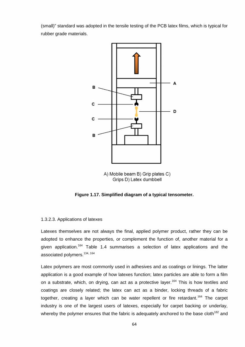
64
(small)” standard was adopted in the tensile testing of the PCB latex films, which is typical for
rubber grade materials.
Figure 1.17. Simplified diagram of a typical tensometer.
1.3.2.3. Applications of latexes
Latexes themselves are not always the final, applied polymer product, rather they can be
adopted to enhance the properties, or complement the function of, another material for a
given application.164 Table 1.4 summarises a selection of latex applications and the
associated polymers.134, 164
Latex polymers are most commonly used in adhesives and as coatings or linings. The latter
application is a good example of how latexes function; latex particles are able to form a film
on a substrate, which, on drying, can act as a protective layer.164 This is how textiles and
coatings are closely related; the latex can act as a binder, locking threads of a fabric
together, creating a layer which can be water repellent or fire retardant.164 The carpet
industry is one of the largest users of latexes, especially for carpet backing or underlay,
whereby the polymer ensures that the fabric is adequately anchored to the base cloth182 and
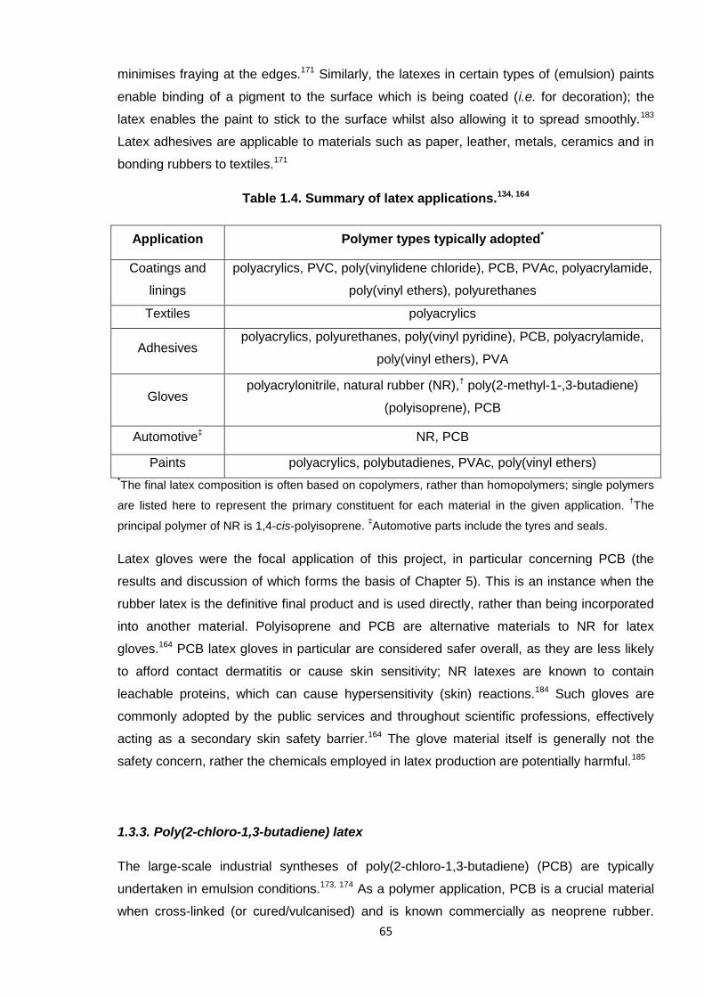
65
minimises fraying at the edges.171 Similarly, the latexes in certain types of (emulsion) paints
enable binding of a pigment to the surface which is being coated (i.e. for decoration); the
latex enables the paint to stick to the surface whilst also allowing it to spread smoothly.183
Latex adhesives are applicable to materials such as paper, leather, metals, ceramics and in
bonding rubbers to textiles.171
Table 1.4. Summary of latex applications.134, 164
Application Polymer types typically adopted*
Coatings and
linings
polyacrylics, PVC, poly(vinylidene chloride), PCB, PVAc, polyacrylamide,
poly(vinyl ethers), polyurethanes
Textiles polyacrylics
Adhesivespolyacrylics, polyurethanes, poly(vinyl pyridine), PCB, polyacrylamide,
poly(vinyl ethers), PVA
Glovespolyacrylonitrile, natural rubber (NR),† poly(2-methyl-1-,3-butadiene)
(polyisoprene), PCB
Automotive‡ NR, PCB
Paints polyacrylics, polybutadienes, PVAc, poly(vinyl ethers)*The final latex composition is often based on copolymers, rather than homopolymers; single polymers
are listed here to represent the primary constituent for each material in the given application.†The
principal polymer of NR is 1,4-cis-polyisoprene.‡Automotive parts include the tyres and seals.
Latex gloves were the focal application of this project, in particular concerning PCB (the
results and discussion of which forms the basis of Chapter 5). This is an instance when the
rubber latex is the definitive final product and is used directly, rather than being incorporated
into another material. Polyisoprene and PCB are alternative materials to NR for latex
gloves.164 PCB latex gloves in particular are considered safer overall, as they are less likely
to afford contact dermatitis or cause skin sensitivity; NR latexes are known to contain
leachable proteins, which can cause hypersensitivity (skin) reactions.184 Such gloves are
commonly adopted by the public services and throughout scientific professions, effectively
acting as a secondary skin safety barrier.164 The glove material itself is generally not the
safety concern, rather the chemicals employed in latex production are potentially harmful.185
1.3.3. Poly(2-chloro-1,3-butadiene) latex
The large-scale industrial syntheses of poly(2-chloro-1,3-butadiene) (PCB) are typically
undertaken in emulsion conditions.173, 174 As a polymer application, PCB is a crucial material
when cross-linked (or cured/vulcanised) and is known commercially as neoprene rubber.
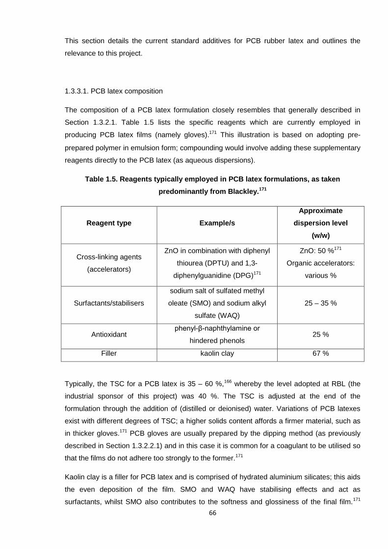
66
This section details the current standard additives for PCB rubber latex and outlines the
relevance to this project.
1.3.3.1. PCB latex composition
The composition of a PCB latex formulation closely resembles that generally described in
Section 1.3.2.1. Table 1.5 lists the specific reagents which are currently employed in
producing PCB latex films (namely gloves).171 This illustration is based on adopting pre-
prepared polymer in emulsion form; compounding would involve adding these supplementary
reagents directly to the PCB latex (as aqueous dispersions).
Table 1.5. Reagents typically employed in PCB latex formulations, as taken
predominantly from Blackley.171
Reagent type Example/s
Approximate
dispersion level
(w/w)
Cross-linking agents
(accelerators)
ZnO in combination with diphenyl
thiourea (DPTU) and 1,3-
diphenylguanidine (DPG)171
ZnO: 50 %171
Organic accelerators:
various %
Surfactants/stabilisers
sodium salt of sulfated methyl
oleate (SMO) and sodium alkyl
sulfate (WAQ)
25 – 35 %
Antioxidantphenyl-β-naphthylamine or
hindered phenols25 %
Filler kaolin clay 67 %
Typically, the TSC for a PCB latex is 35 – 60 %,166 whereby the level adopted at RBL (the
industrial sponsor of this project) was 40 %. The TSC is adjusted at the end of the
formulation through the addition of (distilled or deionised) water. Variations of PCB latexes
exist with different degrees of TSC; a higher solids content affords a firmer material, such as
in thicker gloves.171 PCB gloves are usually prepared by the dipping method (as previously
described in Section 1.3.2.2.1) and in this case it is common for a coagulant to be utilised so
that the films do not adhere too strongly to the former.171
Kaolin clay is a filler for PCB latex and is comprised of hydrated aluminium silicates; this aids
the even deposition of the film. SMO and WAQ have stabilising effects and act as
surfactants, whilst SMO also contributes to the softness and glossiness of the final film.171
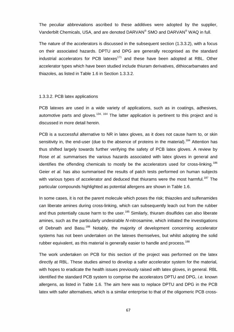
67
The peculiar abbreviations ascribed to these additives were adopted by the supplier,
Vanderbilt Chemicals, USA, and are denoted DARVAN® SMO and DARVAN® WAQ in full.
The nature of the accelerators is discussed in the subsequent section (1.3.3.2), with a focus
on their associated hazards. DPTU and DPG are generally recognised as the standard
industrial accelerators for PCB latexes171 and these have been adopted at RBL. Other
accelerator types which have been studied include thiuram derivatives, dithiocarbamates and
thiazoles, as listed in Table 1.6 in Section 1.3.3.2.
1.3.3.2. PCB latex applications
PCB latexes are used in a wide variety of applications, such as in coatings, adhesives,
automotive parts and gloves.134, 164 The latter application is pertinent to this project and is
discussed in more detail herein.
PCB is a successful alternative to NR in latex gloves, as it does not cause harm to, or skin
sensitivity in, the end-user (due to the absence of proteins in the material).184 Attention has
thus shifted largely towards further verifying the safety of PCB latex gloves. A review by
Rose et al. summarises the various hazards associated with latex gloves in general and
identifies the offending chemicals to mostly be the accelerators used for cross-linking.186
Geier et al. has also summarised the results of patch tests performed on human subjects
with various types of accelerator and deduced that thiurams were the most harmful.187 The
particular compounds highlighted as potential allergens are shown in Table 1.6.
In some cases, it is not the parent molecule which poses the risk; thiazoles and sulfenamides
can liberate amines during cross-linking, which can subsequently leach out from the rubber
and thus potentially cause harm to the user.185 Similarly, thiuram disulfides can also liberate
amines, such as the particularly undesirable N-nitrosamine, which initiated the investigations
of Debnath and Basu.188 Notably, the majority of development concerning accelerator
systems has not been undertaken on the latexes themselves, but whilst adopting the solid
rubber equivalent, as this material is generally easier to handle and process.188
The work undertaken on PCB for this section of the project was performed on the latex
directly at RBL. These studies aimed to develop a safer accelerator system for the material,
with hopes to eradicate the health issues previously raised with latex gloves, in general. RBL
identified the standard PCB system to comprise the accelerators DPTU and DPG, i.e. known
allergens, as listed in Table 1.6. The aim here was to replace DPTU and DPG in the PCB
latex with safer alternatives, which is a similar enterprise to that of the oligomeric PCB cross-
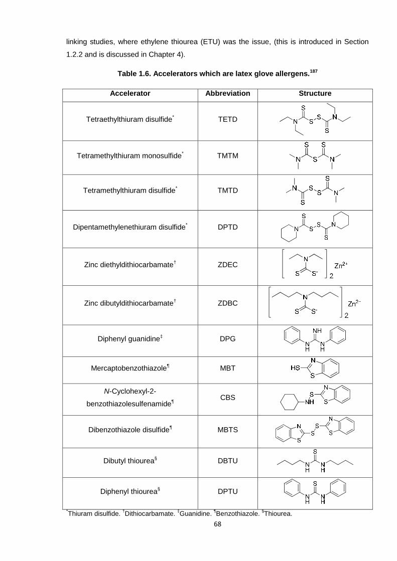
68
linking studies, where ethylene thiourea (ETU) was the issue, (this is introduced in Section
1.2.2 and is discussed in Chapter 4).
Table 1.6. Accelerators which are latex glove allergens.187
Accelerator Abbreviation Structure
Tetraethylthiuram disulfide* TETD
Tetramethylthiuram monosulfide* TMTM
Tetramethylthiuram disulfide* TMTD
Dipentamethylenethiuram disulfide* DPTD
Zinc diethyldithiocarbamate† ZDEC
Zinc dibutyldithiocarbamate† ZDBC
Diphenyl guanidine‡ DPG
Mercaptobenzothiazole¶ MBT
N-Cyclohexyl-2-
benzothiazolesulfenamide¶CBS
Dibenzothiazole disulfide¶ MBTS
Dibutyl thiourea§ DBTU
Diphenyl thiourea§ DPTU
*Thiuram disulfide.
†Dithiocarbamate.
‡Guanidine.
¶Benzothiazole.
§Thiourea.
69
There are few studies in the literature concerning the development of PCB latex; it is strongly
expected that industrial research teams have not necessarily publicised their work openly as
they wish to retain the Intellectual Property (IP) of their findings. One particular report,
however, does concern PCB latex but this focusses on using silica as a filler and optimises
the dispersion thereof by ultrasonication; this research was not concerned with altering the
standard DPTU/DPG accelerator system.170
It is common for systems to comprise two active organic accelerator compounds, i.e. they act
in a binary fashion. As described by Mathew et al.,189 and Debnath and Basu,188 accelerators
can complement, and be activated by, one another. For instance, thiazole-based derivatives,
such as CBS, MBT and MBTS, or thioureas, can work efficiently with thiuram disulfides.188, 189
Both of these particular studies, however, were concerned with NR and used selected
allergens (listed previously in Table 1.6).
One report of particular interest is that of Ohbi et al., who developed a novel accelerator
system comprising a xanthogen polysulfide.185 This work aimed to replace the standard
sulfenamide- and thiazole-based accelerators in bromobutyl rubber (BIIR, which incorporates
isobutylene and brominated isoprene units); the same health issue was being addressed, to
avoid residues leaching out from the rubber material. Diisopropyl xanthogen polysulfide
(DIXP), illustrated in Figure 1.18, was found to be a successful alternative, as it did not
liberate any residual by-products during the cross-linking reaction. The rubber produced
using this accelerator afforded comparable physical properties to that formed via the original
composition.185 Given that the copolymer of BIIR comprises polyisoprene units, this new type
of accelerator was a worthy contender for these studies with PCB, as both of these polymer
backbones are butadiene-based.
Figure 1.18. Structure of diisopropyl xanthogen polysulfide (DIXP), where n = 3, 4 or 5.
70
1.4. Aims
Poly(2-chloro-13-butadiene) (PCB) exists as one of the most widely used elastomers,
boasting exceptional chemical and physical properties. Cross-linking introduces a three-
dimensional network into the polymer which ultimately affords the favourable properties of
this material; this is typically achieved through the use of ethylene thiourea (ETU). Concerns
have arisen regarding the carcinogenic nature of this compound and so an alternative
reagent was sought which should perform in the same way. The manner in which ETU cross-
links PCB has not been resolved; one of the objectives of the Europe-wide “SafeRubber”
campaign was to elucidate the reaction mechanism. Both low molecular weight polymer (i.e.
oligomers) and the PCB rubber was investigated separately by the author and K. Berry,
respectively. This collaborative effort characterised the cross-linking reactions physically,
through tensile testing, and using spectroscopic techniques; the use of oligomers was
anticipated to offer a greater insight into the chemistry taking place. In elucidating the
mechanism, the SafeRubber consortium looked to replace ETU in the cross-linking of PCB
with a non-toxic alternative.
PCB is synthesised industrially via conventional free radical polymerisation in emulsion
conditions, which cannot accurately and reproducibly predefine the molecular weight. The
initial objective of this PhD project was to design a controlled polymerisation system which
enabled the predetermination of low molecular weight PCB, which was subsequently
intended for cross-linking investigations. It was conceivable that reversible addition-
fragmentation chain transfer (RAFT) polymerisation would facilitate this, as it is arguably the
most versatile, straightforward controlled-radical technique. RAFT was a novel enterprise for
PCB, as this method had not been successfully adopted for this polymer to-date.
The second industrial contribution to this PhD project was in developing an alternative
accelerator system for PCB latex. Diphenyl thiourea (DPTU) and diphenyl guanidine (DPG)
are the standard compounds employed in the industrial production of PCB latex gloves, but
these chemicals are known allergens. Thus, this binary accelerator system should be
replaced by non-hazardous compounds which are able to yield PCB latex of a similar grade.
Investigations proceeded by furnishing various PCB latexes with alternative reagents and
assessing their relative performances in tensile tests.
71
1.5. References
1. G. Odian, Principles of Polymerization, Wiley Interscience, New York, 1991.2. B. M. Mandal, Fundamentals of Polymerization, World Scientific, Singapore, 2013.3. J. M. G. Cowie, Polymers: Chemistry & Physics of Modern Materials, Chapham & Hall, Bath,
1991.4. W. H. Carothers, Chem. Rev., 1931, 8, 353-426.5. J. I. Cunneen, E. H. Farmer and H. P. Koch, J. Chem. Soc., 1943, 472-476.6. US Pat., 4581429, 1986.7. M. Kato, M. Kamigaito, M. Sawamoto and T. Higashimura, Macromolecules, 1995, 28, 1721-
1723.8. J.-S. Wang and K. Matyjaszewski, J. Am. Chem. Soc., 1995, 117, 5614-5615.9. T. P. T. Le, G. Moad, E. Rizzardo and S. H. Thang, Chem. Abst., 1998, 128, 115390.10. C. J. Hawker, A. W. Bosman and E. Harth, Chem. Rev., 2001, 101, 3661-3688.11. G. Moad, E. Rizzardo and S. H. Thang, Acc. Chem. Res., 2008, 41, 1133-1142.12. M. P. Stevens, Polymer Chemistry: An Introduction, Oxford University Press, New York, 1990.13. J. P. Van Hook and A. V. Tobolsky, J. Am. Chem. Soc., 1958, 80, 779-782.14. D. R. Hensley, S. D. Goodrich, A. Y. Huckstep, H. J. Harwood and P. L. Rinaldi,
Macromolecules, 1995, 28, 1586-1591.15. J. Carraher, C. E., Introduction to Polymer Chemistry, Taylor and Francis Group, Boca Raton,
2010.16. F. R. Mayo, J. Am. Chem. Soc., 1943, 65, 2324-2329.17. G. Moad and D. H. Solomon, The Chemistry of Free Radical Polymerization, Elsevier Science,
Oxford, 1995.18. R. J. Young and P. A. Lovell, Introduction to Polymers, Chapman and Hall, London, 1991.19. R. P. Babu and R. Dhamodharan, Polym. Int., 2008, 57, 365-371.20. M. R. Wood, D. J. Duncalf, P. Findlay, S. P. Rannard and S. Perrier, Aust. J. Chem., 2007, 60,
772-778.21. S. Perrier and P. Takolpuckdee, J. Polym. Sci. Part A: Polym. Chem., 2005, 43, 5347-5393.22. M. Tatsumi and S. Yamamoto, Polym. Bull., 1983, 10, 452-457.23. S. Slomkowski, J. V. Aleman, R. G. Gilbert, M. Hess, K. Horie, R. G. Jones, P. Kubisa, I.
Meisel, W. Mormann, S. Penczek and R. F. T. Stepto, Pure Appl. Chem., 2011, 83, 2229-2259.
24. D. C. Blackley, Emulsion Polymerisation - Theory and Practice, Applied Science Publishers,London, 1975.
25. J. W. Vanderhoff, J. Polym. Sci. Polym. Sym., 1985, 72, 161-198.26. W. D. Harkins, J. Am. Chem. Soc., 1947, 69, 1428-1444.27. S. Schulze and H. Vogel, Chem. Eng. Technol., 1998, 21, 829-837.28. N. Pullan, M. Liu and P. D. Topham, Polym. Chem., 2013, 4, 2272-2277.29. P. D. Topham, N. Sandon, E. S. Read, J. Madsen, A. J. Ryan and S. P. Armes,
Macromolecules, 2008, 41, 9542-9547.30. C. E. Barnes, J. Am. Chem. Soc., 1945, 67, 217-220.31. M. Save, Y. Guillaneuf and R. G. Gilbert, Aust. J. Chem., 2006, 59, 693-711.32. M. Szwarc, M. Levy and R. Milkovich, J. Am. Chem. Soc., 1956, 78, 2656-2657.33. M. Szwarc, Die Makromolekulare Chemie, 1960, 35, 132-158.34. O. W. Webster, W. R. Hertler, D. Y. Sogah, W. B. Farnham and T. V. RajanBabu, J. Am.
Chem. Soc., 1983, 105, 5706-5708.35. W. R. Hertler, D. Y. Sogah, O. W. Webster and B. M. Trost, Macromolecules, 1984, 17, 1415-
1417.36. O. W. Webster, J. Polym. Sci. Part A: Polym. Chem., 2000, 38, 2855-2860.37. D. Y. Sogah, W. R. Hertler, O. W. Webster and G. M. Cohen, Macromolecules, 1987, 20,
1473-1488.38. D. M. Haddleton and M. C. Crossman, Macromol. Chem. Phys., 1997, 198, 871-881.39. A. D. Jenkins, E. Tsartolia, D. R. M. Walton, J. Horská-Jenkins, P. Kratochvíl and J. Stejskal,
Die Makromolekulare Chemie, 1990, 191, 2511-2520.40. C. S. Patrickios, W. R. Hertler, N. L. Abbott and T. A. Hatton, Macromolecules, 1994, 27, 930-
937.41. T. C. Krasia and C. S. Patrickios, Polymer, 2002, 43, 2917-2920.42. R. Zhuang and A. H. E. Mueller, Macromolecules, 1995, 28, 8043-8050.43. P. F. W. Simon and A. H. E. Müller, Macromolecules, 2001, 34, 6206-6213.44. C. N. Costa and C. S. Patrickios, J. Polym. Sci. Part A: Polym. Chem., 1999, 37, 1597-1607.45. J. Zhang, M. Wang, J. Wang, Y. Shi, J. Tao and D. Wang, Polym. Bull., 2005, 54, 157-161.
72
46. M. Eggert and R. Freitag, J. Polym. Sci. Part A: Polym. Chem., 1994, 32, 803-813.47. C. W. Bielawski and R. H. Grubbs, Prog. Polym. Sci., 2007, 32, 1-29.48. S. Aoshima and S. Kanaoka, Chem. Rev., 2009, 109, 5245-5287.49. N. E. Kamber, W. Jeong, R. M. Waymouth, R. C. Pratt, B. G. G. Lohmeijer and J. L. Hedrick,
Chem. Rev., 2007, 107, 5813-5840.50. K. Matyjaszewski and J. Xia, Chem. Rev., 2001, 101, 2921-2990.51. S. C. Farmer and T. E. Patten, J. Polym. Sci., Part A: Polym. Chem., 2002, 40, 555-563.52. T. B. Zheltonozhskaya, S. V. Fedorchuk and V. G. Syromyatnikov, Russ. Chem. Rev., 2007,
76, 731-765.53. G. Moad, E. Rizzardo and S. H. Thang, Aust. J. Chem., 2005, 58, 379-410.54. P. B. Zetterlund, Y. Kagawa and M. Okubo, Chem. Rev., 2008, 108, 3747-3794.55. S. Penczek and G. Moad, Pure Appl. Chem., 2008, 80, 2163-2193.56. P. J. MacLeod, R. Barber, P. G. Odell, B. Keoshkerian and M. K. Georges, Macromol. Symp.,
2000, 155, 31-38.57. L. I. Gabaston, R. A. Jackson and S. P. Armes, Macromolecules, 1998, 31, 2883-2888.58. P. Lacroix-Desmazes, P. Andre, J. M. Desimone, A.-V. Ruzette and B. Boutevin, J. Polym.
Sci. Part A: Polym. Chem., 2004, 42, 3537-3552.59. E. Bultz and T. P. Bender, Macromolecules, 2011, 44, 3666-3669.60. Y. Guo, M. E. Tysoe and P. B. Zetterlund, Polym. Chem., 2013, 4, 3256-3264.61. C. Detrembleur, C. Jerome, J. De Winter, P. Gerbaux, J.-L. Clement, Y. Guillaneuf and D.
Gigmes, Polym. Chem., 2014, 5, 335-340.62. C. Marestin, C. Noël, A. Guyot and J. Claverie, Macromolecules, 1998, 31, 4041-4044.63. D. Greszta and K. Matyjaszewski, J. Polym. Sci. Part A: Polym. Chem., 1997, 35, 1857-1861.64. D. S. Germack and K. L. Wooley, J. Polym. Sci., Part A: Polym. Chem., 2007, 45, 4100-4108.65. J. He, J. Chen, L. Li, J. Pan, C. Li, J. Cao, Y. Tao, F. Hua, Y. Yang, G. E. McKee and S.
Brinkmann, Polymer, 2000, 41, 4573-4577.66. K. Min, H. Gao and K. Matyjaszewski, Macromolecules, 2007, 40, 1789-1791.67. H. Fischer, J. Polym. Sci. Part A: Polym. Chem., 1999, 37, 1885-1901.68. W. Jakubowski, K. Min and K. Matyjaszewski, Macromolecules, 2005, 39, 39-45.69. J. Xia and K. Matyjaszewski, Macromolecules, 1997, 30, 7692-7696.70. G. Moineau, P. Dubois, R. Jérôme, T. Senninger and P. Teyssié, Macromolecules, 1998, 31,
545-547.71. W. Jakubowski and K. Matyjaszewski, Macromolecules, 2005, 38, 4139-4146.72. H. Tang, M. Radosz and Y. Shen, Macromol. Rapid Commun., 2006, 27, 1127-1131.73. H. Dong, W. Tang and K. Matyjaszewski, Macromolecules, 2007, 40, 2974-2977.74. W. Jakubowski, B. Kirci-Denizli, R. R. Gil and K. Matyjaszewski, Macromol. Chem. Phys.,
2008, 209, 32-39.75. A. Simakova, S. E. Averick, D. Konkolewicz and K. Matyjaszewski, Macromolecules, 2012, 45,
6371-6379.76. K. Mukumoto, Y. Wang and K. Matyjaszewski, ACS Macro Lett., 2012, 1, 599-602.77. X.-h. Liu, J. Wang, F.-j. Zhang, S.-l. An, Y.-l. Ren, Y.-h. Yu, P. Chen and S. Xie, J. Polym. Sci.
Part A: Polym. Chem., 2012, 50, 4358-4364.78. G. Zhu, L. Zhang, Z. Zhang, J. Zhu, Y. Tu, Z. Cheng and X. Zhu, Macromolecules, 2011, 44,
3233-3239.79. S. Perrier, P. Takolpuckdee, J. Westwood and D. M. Lewis, Macromolecules, 2004, 37, 2709-
2717.80. J. B. McLeary and B. Klumperman, Soft Matter, 2006, 2, 45-53.81. G. Moad, E. Rizzardo and S. H. Thang, Aust. J. Chem., 2009, 62, 1402-1472.82. J. Chiefari, Y. K. Chong, F. Ercole, J. Krstina, J. Jeffery, T. P. T. Le, R. T. A. Mayadunne, G.
F. Mejis, C. L. Moad, G. Moad, E. Rizzardo and S. H. Thang, Macromolecules, 1998, 31,5559-5562.
83. G. Moad, E. Rizzardo and S. H. Thang, Aust. J. Chem., 2006, 59, 669-692.84. G. Moad, E. Rizzardo and S. H. Thang, Polymer, 2008, 49, 1079-1131.85. D. J. Keddie, G. Moad, E. Rizzardo and S. H. Thang, Macromolecules, 2012, 45, 5321-5342.86. E. Rizzardo, J. Chiefari, Y. K. Chong, F. Ercole, J. Krstina, J. Jeffery, T. P. T. Le, R. T. A.
Mayadunne, G. F. Mejis, C. L. Moad, G. Moad and S. H. Thang, Macromol. Symp., 1999, 143,291-307.
87. Y. K. Chong, J. Krstina, T. P. T. Le, G. Moad, A. Postma, E. Rizzardo and S. H. Thang,Macromolecules, 2003, 36, 2256-2272.
88. J. Chiefari, R. T. A. Mayadunne, C. L. Moad, G. Moad, E. Rizzardo, A. Postma, M. A.Skidmore and S. H. Thang, Macromolecules, 2003, 36, 2273-2283.
89. Y. Zhou, J. He, C. Li, L. Hong and Y. Yang, Macromolecules, 2011, 44, 8446-8457.
73
90. V. Jitchum and S. Perrier, Macromolecules, 2007, 40, 1408-1412.91. B. Chong, G. Moad, E. Rizzardo, M. A. Skidmore and S. H. Thang, Aust. J. Chem., 2006, 59,
755-762.92. J. Xu, J. He, D. Fan, W. Tang and Y. Yang, Macromolecules, 2006, 39, 3753-3759.93. C. Li and B. C. Benicewicz, J. Polym. Sci., Part A: Polym. Chem., 2005, 43, 1535-1543.94. O. I. Strube, L. Nothdurft, M. Drache and G. Schmidt-Naake, Macromol. Chem. Phys., 2011,
212, 574-582.95. M. Benaglia, E. Rizzardo, A. Alberti and M. Guerra, Macromolecules, 2005, 38, 3129-3140.96. A. Goto, K. Sato, Y. Tsujii, T. Fukuda, G. Moad, E. Rizzardo and S. H. Thang,
Macromolecules, 2001, 34, 402-408.97. M. H. Allen, S. T. Hemp, A. E. Smith and T. E. Long, Macromolecules, 2012, 45, 3669-3676.98. C. J. Ferguson, R. J. Hughes, B. T. T. Pham, B. S. Hawkett, R. G. Gilbert, A. K. Serelis and C.
H. Such, Macromolecules, 2002, 35, 9243-9245.99. S. W. Prescott, M. J. Ballard, E. Rizzardo and R. G. Gilbert, Macromolecules, 2002, 35, 5417-
5425.100. C. J. Dürr, S. G. J. Emmerling, A. Kaiser, S. Brandau, A. K. T. Habicht, M. Klimpel and C.
Barner-Kowollik, J. Polym. Sci. Part A: Polym. Chem., 2012, 50, 174-180.101. J. Jennings, M. Beija, J. T. Kennon, H. Willcock, R. K. O’Reilly, S. Rimmer and S. M. Howdle,
Macromolecules, 2013, 46, 6843-6851.102. J. Jennings, M. Beija, A. P. Richez, S. D. Cooper, P. E. Mignot, K. J. Thurecht, K. S. Jack and
S. M. Howdle, J. Am. Chem. Soc., 2012, 134, 4772-4781.103. J. Zhou, S. Villarroya, W. Wang, M. F. Wyatt, C. J. Duxbury, K. J. Thurecht and S. M. Howdle,
Macromolecules, 2006, 39, 5352-5358.104. H. M. Woods, M. M. C. G. Silva, C. Nouvel, K. M. Shakesheff and S. M. Howdle, J. Mater.
Chem., 2004, 14, 1663-1678.105. S. Kanagasabapathy, A. Sudalai and B. C. Benicewicz, Macromol. Rapid Commun., 2001, 22,
1076-1080.106. J. B. McLeary, F. M. Calitz, J. M. McKenzie, M. P. Tonge, R. D. Sanderson and B.
Klumperman, Macromolecules, 2004, 37, 2383-2394.107. S. E. Shim, H. Lee and S. Choe, Macromolecules, 2004, 37, 5565-5571.108. T. Arita, M. Buback and P. Vana, Macromolecules, 2005, 38, 7935-7943.109. J. D. Flores, J. Shin, C. E. Hoyle and C. L. McCormick, Polym. Chem., 2010, 1, 213-220.110. A. J. Convertine, N. Ayres, C. W. Scales, A. B. Lowe and C. L. McCormick,
Biomacromolecules, 2004, 5, 1177-1180.111. J. F. Quinn, E. Rizzardo and T. P. Davis, Chem. Commun., 2001, 1044-1045.112. A. Favier and M.-T. Charreyre, Macromol. Rapid Commun., 2006, 27, 653-692.113. J. Rzayev and J. Penelle, Angew. Chem., 2004, 116, 1723-1726.114. J. Rzayev and J. Penelle, Macromolecules, 2002, 35, 1489-1490.115. C. M. Blow and C. Hepburn, eds., Rubber Technology and Manufacture, Butterworths,
London, 1982.116. C. D. Vo, D. Kuckling, H. J. P. Adler and M. Schönhoff, Colloid Polym Sci, 2002, 280, 400-
409.117. H. A. Khonakdar, J. Morshedian, U. Wagenknecht and S. H. Jafari, Polymer, 2003, 44, 4301-
4309.118. X.-R. Zeng and T.-M. Ko, J. Appl. Polym. Sci., 1998, 67, 2131-2140.119. J.-M. Charrier, Polymeric Materials and Processing: Plastics, Elastomers and Composites,
Hanser, New York, 1990.120. M. Krumova, D. López, R. Benavente, C. Mijangos and J. M. Pereña, Polymer, 2000, 41,
9265-9272.121. W. Huang, G. L. Baker and M. L. Bruening, Angew. Chem., 2001, 113, 1558-1560.122. H. L. Fisher, Ind. Eng. Chem. Res., 1939, 31, 1381-1389.123. L. D. Loan, J. Polym. Sci., Part A: Gen. Pap., 1964, 2, 3053-3066.124. C. Jiao, Z. Wang, Z. Gui and Y. Hu, Eur. Polym. J., 2005, 41, 1204-1211.125. A. Oshima, S. Ikeda, E. Katoh and Y. Tabata, Radiat. Phys. Chem., 2001, 62, 39-45.126. M. N. Ismail, M. S. Ibrahim and M. A. Abd El-Ghaffar, Polym. Degrad. Stabil., 1998, 62, 337-
341.127. N. Rattanasom, T. Saowapark and C. Deeprasertkul, Polym. Test., 2007, 26, 369-377.128. S. Dasgupta, S. L. Agrawal, S. Bandyopadhyay, S. Chakraborty, R. Mukhopadhyay, R. K.
Malkani and S. C. Ameta, Polym. Test., 2008, 27, 277-283.129. G. Heideman, R. N. Datta, J. W. M. Noordermeer and B. v. Baarle, J. Appl. Polym. Sci., 2005,
95, 1388-1404.
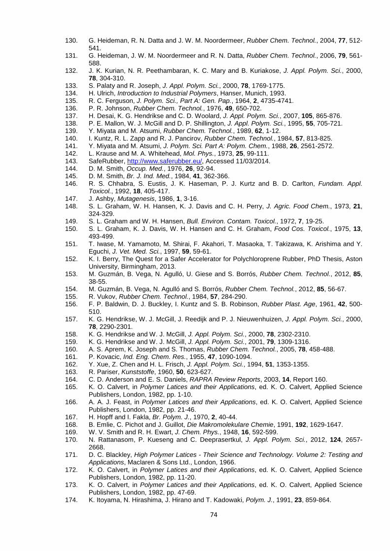
74
130. G. Heideman, R. N. Datta and J. W. M. Noordermeer, Rubber Chem. Technol., 2004, 77, 512-541.
131. G. Heideman, J. W. M. Noordermeer and R. N. Datta, Rubber Chem. Technol., 2006, 79, 561-588.
132. J. K. Kurian, N. R. Peethambaran, K. C. Mary and B. Kuriakose, J. Appl. Polym. Sci., 2000,78, 304-310.
133. S. Palaty and R. Joseph, J. Appl. Polym. Sci., 2000, 78, 1769-1775.134. H. Ulrich, Introduction to Industrial Polymers, Hanser, Munich, 1993.135. R. C. Ferguson, J. Polym. Sci., Part A: Gen. Pap., 1964, 2, 4735-4741.136. P. R. Johnson, Rubber Chem. Technol., 1976, 49, 650-702.137. H. Desai, K. G. Hendrikse and C. D. Woolard, J. Appl. Polym. Sci., 2007, 105, 865-876.138. P. E. Mallon, W. J. McGill and D. P. Shillington, J. Appl. Polym. Sci., 1995, 55, 705-721.139. Y. Miyata and M. Atsumi, Rubber Chem. Technol., 1989, 62, 1-12.140. I. Kuntz, R. L. Zapp and R. J. Pancirov, Rubber Chem. Technol., 1984, 57, 813-825.141. Y. Miyata and M. Atsumi, J. Polym. Sci. Part A: Polym. Chem., 1988, 26, 2561-2572.142. L. Krause and M. A. Whitehead, Mol. Phys., 1973, 25, 99-111.143. SafeRubber, http://www.saferubber.eu/, Accessed 11/03/2014.144. D. M. Smith, Occup. Med., 1976, 26, 92-94.145. D. M. Smith, Br. J. Ind. Med., 1984, 41, 362-366.146. R. S. Chhabra, S. Eustis, J. K. Haseman, P. J. Kurtz and B. D. Carlton, Fundam. Appl.
Toxicol., 1992, 18, 405-417.147. J. Ashby, Mutagenesis, 1986, 1, 3-16.148. S. L. Graham, W. H. Hansen, K. J. Davis and C. H. Perry, J. Agric. Food Chem., 1973, 21,
324-329.149. S. L. Graham and W. H. Hansen, Bull. Environ. Contam. Toxicol., 1972, 7, 19-25.150. S. L. Graham, K. J. Davis, W. H. Hansen and C. H. Graham, Food Cos. Toxicol., 1975, 13,
493-499.151. T. Iwase, M. Yamamoto, M. Shirai, F. Akahori, T. Masaoka, T. Takizawa, K. Arishima and Y.
Eguchi, J. Vet. Med. Sci., 1997, 59, 59-61.152. K. I. Berry, The Quest for a Safer Accelerator for Polychloroprene Rubber, PhD Thesis, Aston
University, Birmingham, 2013.153. M. Guzmán, B. Vega, N. Agulló, U. Giese and S. Borrós, Rubber Chem. Technol., 2012, 85,
38-55.154. M. Guzmán, B. Vega, N. Agulló and S. Borrós, Rubber Chem. Technol., 2012, 85, 56-67.155. R. Vukov, Rubber Chem. Technol., 1984, 57, 284-290.156. F. P. Baldwin, D. J. Buckley, I. Kuntz and S. B. Robinson, Rubber Plast. Age, 1961, 42, 500-
510.157. K. G. Hendrikse, W. J. McGill, J. Reedijk and P. J. Nieuwenhuizen, J. Appl. Polym. Sci., 2000,
78, 2290-2301.158. K. G. Hendrikse and W. J. McGill, J. Appl. Polym. Sci., 2000, 78, 2302-2310.159. K. G. Hendrikse and W. J. McGill, J. Appl. Polym. Sci., 2001, 79, 1309-1316.160. A. S. Aprem, K. Joseph and S. Thomas, Rubber Chem. Technol., 2005, 78, 458-488.161. P. Kovacic, Ind. Eng. Chem. Res., 1955, 47, 1090-1094.162. Y. Xue, Z. Chen and H. L. Frisch, J. Appl. Polym. Sci., 1994, 51, 1353-1355.163. R. Pariser, Kunststoffe, 1960, 50, 623-627.164. C. D. Anderson and E. S. Daniels, RAPRA Review Reports, 2003, 14, Report 160.165. K. O. Calvert, in Polymer Latices and their Applications, ed. K. O. Calvert, Applied Science
Publishers, London, 1982, pp. 1-10.166. A. A. J. Feast, in Polymer Latices and their Applications, ed. K. O. Calvert, Applied Science
Publishers, London, 1982, pp. 21-46.167. H. Hopff and I. Fakla, Br. Polym. J., 1970, 2, 40-44.168. B. Emlie, C. Pichot and J. Guillot, Die Makromolekulare Chemie, 1991, 192, 1629-1647.169. W. V. Smith and R. H. Ewart, J. Chem. Phys., 1948, 16, 592-599.170. N. Rattanasom, P. Kueseng and C. Deeprasertkul, J. Appl. Polym. Sci., 2012, 124, 2657-
2668.171. D. C. Blackley, High Polymer Latices - Their Science and Technology. Volume 2: Testing and
Applications, Maclaren & Sons Ltd., London, 1966.172. K. O. Calvert, in Polymer Latices and their Applications, ed. K. O. Calvert, Applied Science
Publishers, London, 1982, pp. 11-20.173. K. O. Calvert, in Polymer Latices and their Applications, ed. K. O. Calvert, Applied Science
Publishers, London, 1982, pp. 47-69.174. K. Itoyama, N. Hirashima, J. Hirano and T. Kadowaki, Polym. J., 1991, 23, 859-864.
75
175. J. E. L. Joensson, H. Hassander, L. H. Jansson and B. Toernell, Macromolecules, 1991, 24,126-131.
176. J. L. Luna-Xavier, A. Guyot and E. Bourgeat-Lami, J. Colloid. Interface Sci., 2002, 250, 82-92.177. G. Pan, L. Wu, Z. Zhang and D. Li, J. Appl. Polym. Sci., 2002, 83, 1736-1743.178. H.-H. Chu and H.-Y. Hwang, Polym. Bull., 1997, 38, 295-302.179. K. Dimic-Misic, P. A. C. Gane and J. Paltakari, Ind. Eng. Chem. Res., 2013, 52, 16066-16083.180. S. Varghese and J. Karger-Kocsis, Polymer, 2003, 44, 4921-4927.181. S. H. Chang and I. J. Chung, Macromolecules, 1991, 24, 567-571.182. D. Porter, in Polymer Latices and their Applications, ed. K. O. Calvert, Applied Science
Publishers, London, 1982, pp. 71-91.183. K. Sellars and G. R. Brown, in Polymer Latices and their Applications, ed. K. O. Calvert,
Applied Science Publishers, London, 1982, pp. 145-171.184. S. H. Wakelin and I. R. White, Clin. Exp. Dermatol., 1999, 24, 245-248.185. D. S. Ohbi, T. S. Purewal, T. Shah and E. Siores, J. Appl. Polym. Sci., 2007, 106, 526-533.186. R. F. Rose, P. Lyons, H. Horne and S. M. Wilkinson, Contact Dermatitis, 2009, 61, 129-137.187. J. Geier, H. Lessmann, W. Uter and A. Schnuch, Contact Dermatitis, 2003, 48, 39-44.188. S. C. Debnath and D. K. Basu, J. Appl. Polym. Sci., 1996, 60, 845-855.189. C. Mathew, V. T. E. Mini, A. P. Kuriakose and D. J. Francis, J. Appl. Polym. Sci., 1994, 54,
1033-1041.
76
CHAPTER 2
MATERIALS AND EXPERIMENTAL
METHODS
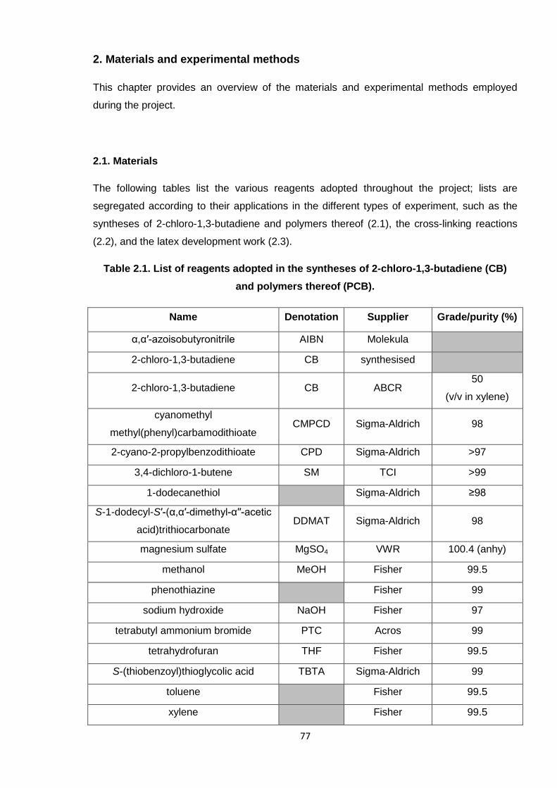
77
2. Materials and experimental methods
This chapter provides an overview of the materials and experimental methods employed
during the project.
2.1. Materials
The following tables list the various reagents adopted throughout the project; lists are
segregated according to their applications in the different types of experiment, such as the
syntheses of 2-chloro-1,3-butadiene and polymers thereof (2.1), the cross-linking reactions
(2.2), and the latex development work (2.3).
Table 2.1. List of reagents adopted in the syntheses of 2-chloro-1,3-butadiene (CB)
and polymers thereof (PCB).
Name Denotation Supplier Grade/purity (%)
α,α′-azoisobutyronitrile AIBN Molekula
2-chloro-1,3-butadiene CB synthesised
2-chloro-1,3-butadiene CB ABCR50
(v/v in xylene)
cyanomethyl
methyl(phenyl)carbamodithioateCMPCD Sigma-Aldrich 98
2-cyano-2-propylbenzodithioate CPD Sigma-Aldrich >97
3,4-dichloro-1-butene SM TCI >99
1-dodecanethiol Sigma-Aldrich ≥98
S-1-dodecyl-S′-(α,α′-dimethyl-α′′-acetic
acid)trithiocarbonateDDMAT Sigma-Aldrich 98
magnesium sulfate MgSO4 VWR 100.4 (anhy)
methanol MeOH Fisher 99.5
phenothiazine Fisher 99
sodium hydroxide NaOH Fisher 97
tetrabutyl ammonium bromide PTC Acros 99
tetrahydrofuran THF Fisher 99.5
S-(thiobenzoyl)thioglycolic acid TBTA Sigma-Aldrich 99
toluene Fisher 99.5
xylene Fisher 99.5
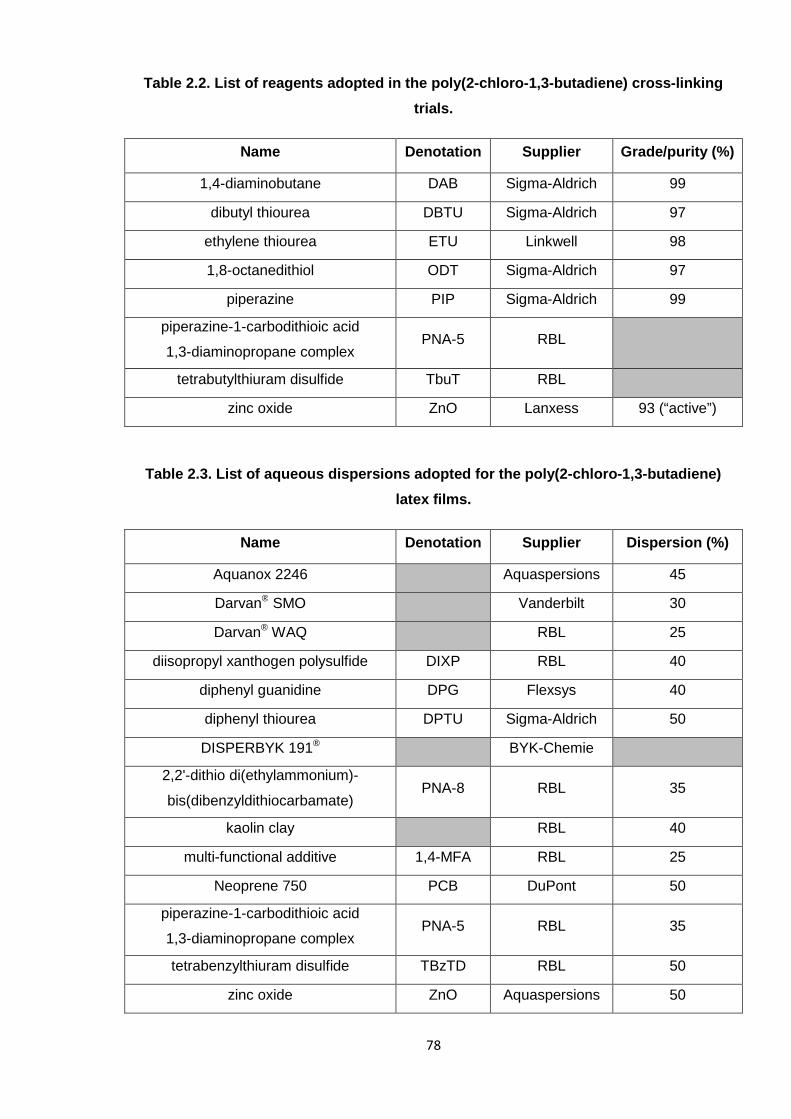
78
Table 2.2. List of reagents adopted in the poly(2-chloro-1,3-butadiene) cross-linking
trials.
Name Denotation Supplier Grade/purity (%)
1,4-diaminobutane DAB Sigma-Aldrich 99
dibutyl thiourea DBTU Sigma-Aldrich 97
ethylene thiourea ETU Linkwell 98
1,8-octanedithiol ODT Sigma-Aldrich 97
piperazine PIP Sigma-Aldrich 99
piperazine-1-carbodithioic acid
1,3-diaminopropane complexPNA-5 RBL
tetrabutylthiuram disulfide TbuT RBL
zinc oxide ZnO Lanxess 93 (“active”)
Table 2.3. List of aqueous dispersions adopted for the poly(2-chloro-1,3-butadiene)
latex films.
Name Denotation Supplier Dispersion (%)
Aquanox 2246 Aquaspersions 45
Darvan® SMO Vanderbilt 30
Darvan® WAQ RBL 25
diisopropyl xanthogen polysulfide DIXP RBL 40
diphenyl guanidine DPG Flexsys 40
diphenyl thiourea DPTU Sigma-Aldrich 50
DISPERBYK 191® BYK-Chemie
2,2'-dithio di(ethylammonium)-
bis(dibenzyldithiocarbamate)PNA-8 RBL 35
kaolin clay RBL 40
multi-functional additive 1,4-MFA RBL 25
Neoprene 750 PCB DuPont 50
piperazine-1-carbodithioic acid
1,3-diaminopropane complexPNA-5 RBL 35
tetrabenzylthiuram disulfide TBzTD RBL 50
zinc oxide ZnO Aquaspersions 50
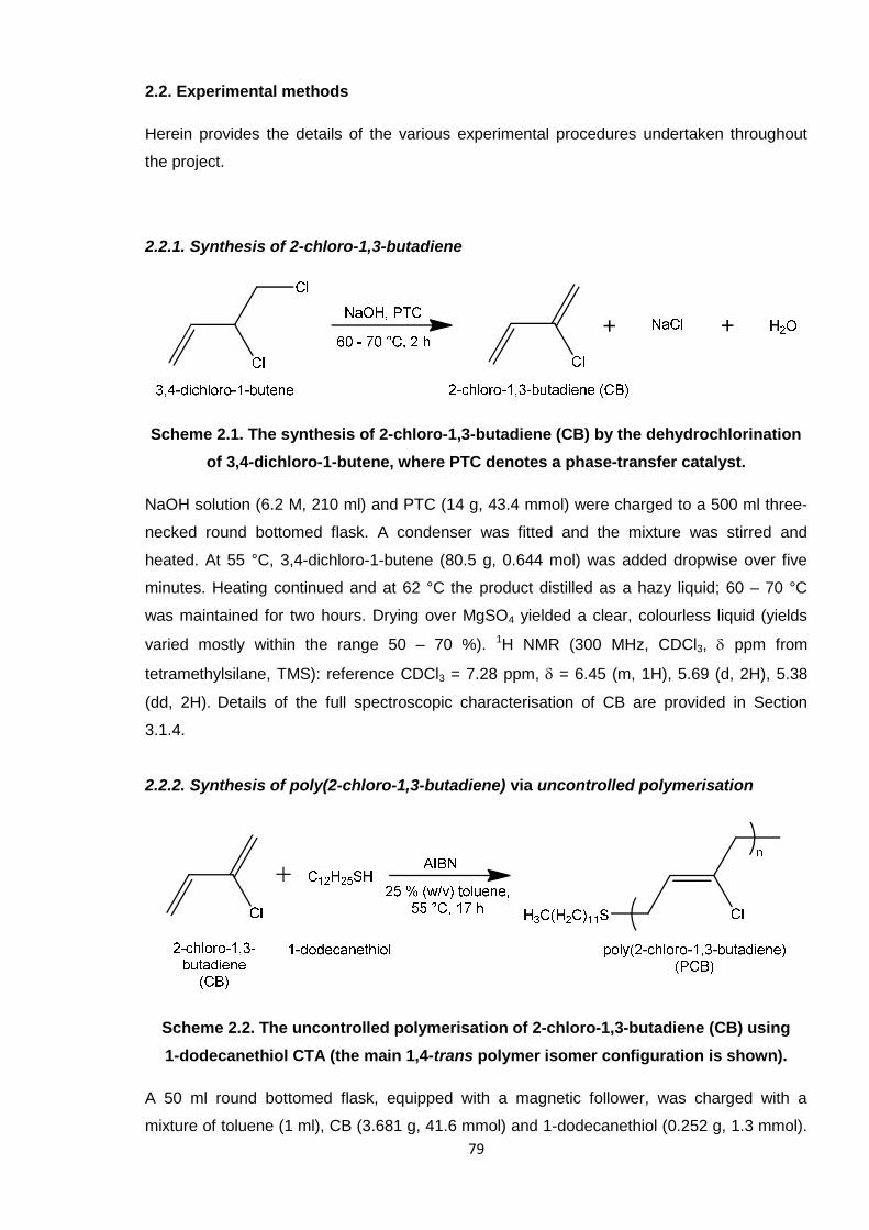
79
2.2. Experimental methods
Herein provides the details of the various experimental procedures undertaken throughout
the project.
2.2.1. Synthesis of 2-chloro-1,3-butadiene
Scheme 2.1. The synthesis of 2-chloro-1,3-butadiene (CB) by the dehydrochlorination
of 3,4-dichloro-1-butene, where PTC denotes a phase-transfer catalyst.
NaOH solution (6.2 M, 210 ml) and PTC (14 g, 43.4 mmol) were charged to a 500 ml three-
necked round bottomed flask. A condenser was fitted and the mixture was stirred and
heated. At 55 °C, 3,4-dichloro-1-butene (80.5 g, 0.644 mol) was added dropwise over five
minutes. Heating continued and at 62 °C the product distilled as a hazy liquid; 60 – 70 °C
was maintained for two hours. Drying over MgSO4 yielded a clear, colourless liquid (yields
varied mostly within the range 50 – 70 %). 1H NMR (300 MHz, CDCl3, ppm from
tetramethylsilane, TMS): reference CDCl3 = 7.28 ppm, = 6.45 (m, 1H), 5.69 (d, 2H), 5.38
(dd, 2H). Details of the full spectroscopic characterisation of CB are provided in Section
3.1.4.
2.2.2. Synthesis of poly(2-chloro-1,3-butadiene) via uncontrolled polymerisation
Scheme 2.2. The uncontrolled polymerisation of 2-chloro-1,3-butadiene (CB) using
1-dodecanethiol CTA (the main 1,4-trans polymer isomer configuration is shown).
A 50 ml round bottomed flask, equipped with a magnetic follower, was charged with a
mixture of toluene (1 ml), CB (3.681 g, 41.6 mmol) and 1-dodecanethiol (0.252 g, 1.3 mmol).
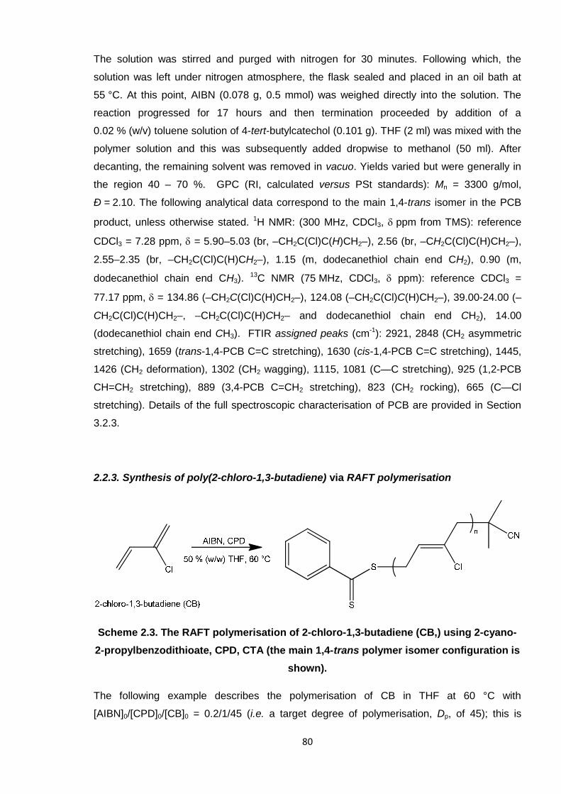
80
The solution was stirred and purged with nitrogen for 30 minutes. Following which, the
solution was left under nitrogen atmosphere, the flask sealed and placed in an oil bath at
55 °C. At this point, AIBN (0.078 g, 0.5 mmol) was weighed directly into the solution. The
reaction progressed for 17 hours and then termination proceeded by addition of a
0.02 % (w/v) toluene solution of 4-tert-butylcatechol (0.101 g). THF (2 ml) was mixed with the
polymer solution and this was subsequently added dropwise to methanol (50 ml). After
decanting, the remaining solvent was removed in vacuo. Yields varied but were generally in
the region 40 – 70 %. GPC (RI, calculated versus PSt standards): Mn = 3300 g/mol,
Ð = 2.10. The following analytical data correspond to the main 1,4-trans isomer in the PCB
product, unless otherwise stated. 1H NMR: (300 MHz, CDCl3, ppm from TMS): reference
CDCl3 = 7.28 ppm, = 5.90–5.03 (br, –CH2C(Cl)C(H)CH2–), 2.56 (br, –CH2C(Cl)C(H)CH2–),
2.55–2.35 (br, –CH2C(Cl)C(H)CH2–), 1.15 (m, dodecanethiol chain end CH2), 0.90 (m,
dodecanethiol chain end CH3).13C NMR (75 MHz, CDCl3, ppm): reference CDCl3 =
77.17 ppm, = 134.86 (–CH2C(Cl)C(H)CH2–), 124.08 (–CH2C(Cl)C(H)CH2–), 39.00-24.00 (–
CH2C(Cl)C(H)CH2–, –CH2C(Cl)C(H)CH2– and dodecanethiol chain end CH2), 14.00
(dodecanethiol chain end CH3). FTIR assigned peaks (cm-1): 2921, 2848 (CH2 asymmetric
stretching), 1659 (trans-1,4-PCB C=C stretching), 1630 (cis-1,4-PCB C=C stretching), 1445,
1426 (CH2 deformation), 1302 (CH2 wagging), 1115, 1081 (C—C stretching), 925 (1,2-PCB
CH=CH2 stretching), 889 (3,4-PCB C=CH2 stretching), 823 (CH2 rocking), 665 (C—Cl
stretching). Details of the full spectroscopic characterisation of PCB are provided in Section
3.2.3.
2.2.3. Synthesis of poly(2-chloro-1,3-butadiene) via RAFT polymerisation
Scheme 2.3. The RAFT polymerisation of 2-chloro-1,3-butadiene (CB,) using 2-cyano-
2-propylbenzodithioate, CPD, CTA (the main 1,4-trans polymer isomer configuration is
shown).
The following example describes the polymerisation of CB in THF at 60 °C with
[AIBN]0/[CPD]0/[CB]0 = 0.2/1/45 (i.e. a target degree of polymerisation, Dp, of 45); this is
81
representative of all polymerisations undertaken during this work. A 50 ml round bottomed
flask, equipped with a magnetic follower, was charged with a mixture of CPD (276 mg,
1.247 mmol), AIBN (39 mg, 0.238 mmol), CB (5.027 g, 56.8 mmol) and THF (5 g). The
solution was stirred and purged with nitrogen for 30 minutes. Following which, the solution
was left under nitrogen atmosphere, the flask sealed and placed in an oil bath at 60 °C.
Aliquots of the solution were taken periodically and the polymerisation was monitored up to
high conversion. Termination proceeded by rapidly cooling the reaction mixture in ice. THF
was added (6 ml) and the resulting polymer solution was added dropwise to methanol
(70 ml). After decanting, the remaining solvent was removed in vacuo, yielding a viscous
dark red liquid. The following analytical data correspond to the main 1,4-trans isomer in the
PCB product, unless otherwise stated. 1H NMR (300 MHz, CDCl3, ppm from TMS):
reference CDCl3 = 7.28 ppm, = 5.90–5.03 (br, –CH2C(Cl)C(H)CH2–), 2.55 (br, –
CH2C(Cl)C(H)CH2–), 2.52–2.25 (br, –CH2C(Cl)C(H)CH2–). 13C NMR (75 MHz, CDCl3,
ppm): reference CDCl3 = 77.17 ppm, = 134.92 (–CH2C(Cl)C(H)CH2–), 124.11 (–
CH2C(Cl)C(H)CH2–), 38.30–26.70 (– CH2C(Cl)C(H)CH2– and –CH2C(Cl)C(H)CH2–). FTIR
assigned peaks (cm-1): 2918, 2857 (CH2 asymmetric stretching), 1660 (trans-1,4-PCB C=C
stretching), 1602 (cis-1,4-PCB C=C stretching), 1444, 1430 (CH2 deformation), 1303 (CH2
wagging), 1115, 1045 (C—C stretching), 827 (CH2 rocking), 667 (C—Cl stretching).
2.2.3.1. Chain extension experiment
The experiment was performed in a similar way to the polymerisation previously described,
but using PCB macroCTA (35 % conv) (976 mg, MnGPC = 1500 g/mol, approx. 0.126 mmol),
AIBN (3.9 mg, 0.024 mmol), THF (1.9 g) and previously distilled (synthesised) CB (1.9 g,
22.1 mmol). The reaction proceeded at 60 °C for 10 hours to yield the final extended, PCB-b-
PCB, material (63 % conv).
2.2.4. Compounding and cross-linking of poly(2-chloro-1,3-butadiene) oligomers
Poly(2-chloro-1,3-butadiene) (PCB) oligomers (~3000 g/mol) synthesised via the
uncontrolled polymerisation method outlined in Section 2.2.2 were predominantly used in
cross-linking studies. The various reaction mixtures are outlined in Table 2.4, where levels
are given in parts per hundred rubber (phr), as is typical within the rubber industry.
For each reaction, the various additives were first weighed accurately into an appropriately-
sized glass vial, followed by addition of the oligomer. Given the high viscosity of the oligomer,
the mixtures were not easily rendered homogeneous, so sonication was often adopted for up
to two hours (or overnight where larger particle sizes existed, whilst ensuring that the
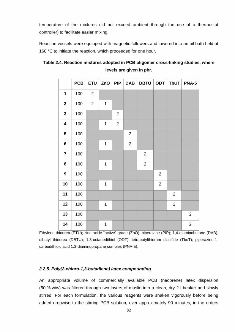
82
temperature of the mixtures did not exceed ambient through the use of a thermostat
controller) to facilitate easier mixing.
Reaction vessels were equipped with magnetic followers and lowered into an oil bath held at
160 °C to initiate the reaction, which proceeded for one hour.
Table 2.4. Reaction mixtures adopted in PCB oligomer cross-linking studies, where
levels are given in phr.
PCB ETU ZnO PIP DAB DBTU ODT TbuT PNA-5
1 100 2
2 100 2 1
3 100 2
4 100 1 2
5 100 2
6 100 1 2
7 100 2
8 100 1 2
9 100 2
10 100 1 2
11 100 2
12 100 1 2
13 100 2
14 100 1 2
Ethylene thiourea (ETU); zinc oxide “active” grade (ZnO); piperazine (PIP); 1,4-diaminobutane (DAB);
dibutyl thiourea (DBTU); 1,8-octanedithiol (ODT); tetrabutylthiuram disulfide (TbuT); piperazine-1-
carbodithioic acid 1,3-diaminopropane complex (PNA-5).
2.2.5. Poly(2-chloro-1,3-butadiene) latex compounding
An appropriate volume of commercially available PCB (neoprene) latex dispersion
(50 % w/w) was filtered through two layers of muslin into a clean, dry 2 l beaker and slowly
stirred. For each formulation, the various reagents were shaken vigorously before being
added dropwise to the stirring PCB solution, over approximately 90 minutes, in the orders
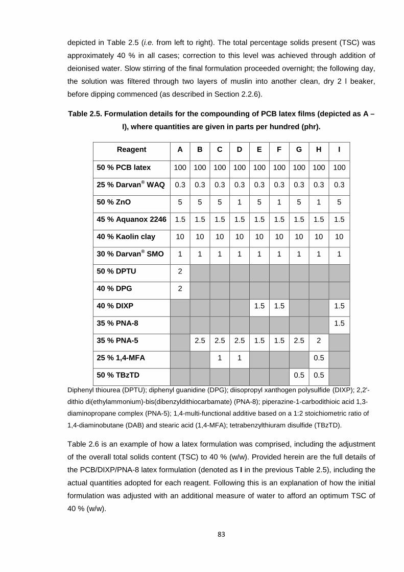
83
depicted in Table 2.5 (i.e. from left to right). The total percentage solids present (TSC) was
approximately 40 % in all cases; correction to this level was achieved through addition of
deionised water. Slow stirring of the final formulation proceeded overnight; the following day,
the solution was filtered through two layers of muslin into another clean, dry 2 l beaker,
before dipping commenced (as described in Section 2.2.6).
Table 2.5. Formulation details for the compounding of PCB latex films (depicted as A –
I), where quantities are given in parts per hundred (phr).
Reagent A B C D E F G H I
50 % PCB latex 100 100 100 100 100 100 100 100 100
25 % Darvan® WAQ 0.3 0.3 0.3 0.3 0.3 0.3 0.3 0.3 0.3
50 % ZnO 5 5 5 1 5 1 5 1 5
45 % Aquanox 2246 1.5 1.5 1.5 1.5 1.5 1.5 1.5 1.5 1.5
40 % Kaolin clay 10 10 10 10 10 10 10 10 10
30 % Darvan® SMO 1 1 1 1 1 1 1 1 1
50 % DPTU 2
40 % DPG 2
40 % DIXP 1.5 1.5 1.5
35 % PNA-8 1.5
35 % PNA-5 2.5 2.5 2.5 1.5 1.5 2.5 2
25 % 1,4-MFA 1 1 0.5
50 % TBzTD 0.5 0.5
Diphenyl thiourea (DPTU); diphenyl guanidine (DPG); diisopropyl xanthogen polysulfide (DIXP); 2,2'-
dithio di(ethylammonium)-bis(dibenzyldithiocarbamate) (PNA-8); piperazine-1-carbodithioic acid 1,3-
diaminopropane complex (PNA-5); 1,4-multi-functional additive based on a 1:2 stoichiometric ratio of
1,4-diaminobutane (DAB) and stearic acid (1,4-MFA); tetrabenzylthiuram disulfide (TBzTD).
Table 2.6 is an example of how a latex formulation was comprised, including the adjustment
of the overall total solids content (TSC) to 40 % (w/w). Provided herein are the full details of
the PCB/DIXP/PNA-8 latex formulation (denoted as I in the previous Table 2.5), including the
actual quantities adopted for each reagent. Following this is an explanation of how the initial
formulation was adjusted with an additional measure of water to afford an optimum TSC of
40 % (w/w).
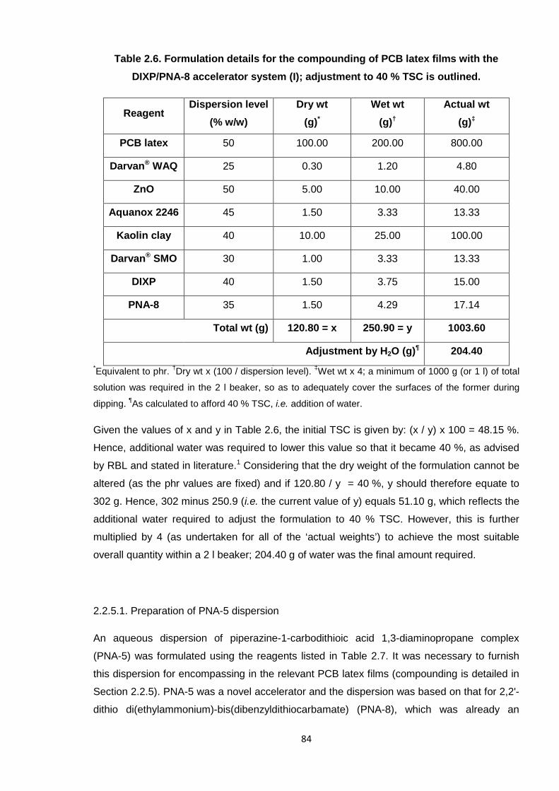
84
Table 2.6. Formulation details for the compounding of PCB latex films with the
DIXP/PNA-8 accelerator system (I); adjustment to 40 % TSC is outlined.
ReagentDispersion level
(% w/w)
Dry wt
(g)*
Wet wt
(g)†
Actual wt
(g)‡
PCB latex 50 100.00 200.00 800.00
Darvan® WAQ 25 0.30 1.20 4.80
ZnO 50 5.00 10.00 40.00
Aquanox 2246 45 1.50 3.33 13.33
Kaolin clay 40 10.00 25.00 100.00
Darvan® SMO 30 1.00 3.33 13.33
DIXP 40 1.50 3.75 15.00
PNA-8 35 1.50 4.29 17.14
Total wt (g) 120.80 = x 250.90 = y 1003.60
Adjustment by H2O (g)¶ 204.40
*Equivalent to phr.
†Dry wt x (100 / dispersion level).
‡Wet wt x 4; a minimum of 1000 g (or 1 l) of total
solution was required in the 2 l beaker, so as to adequately cover the surfaces of the former during
dipping.¶As calculated to afford 40 % TSC, i.e. addition of water.
Given the values of x and y in Table 2.6, the initial TSC is given by: (x / y) x 100 = 48.15 %.
Hence, additional water was required to lower this value so that it became 40 %, as advised
by RBL and stated in literature.1 Considering that the dry weight of the formulation cannot be
altered (as the phr values are fixed) and if 120.80 / y = 40 %, y should therefore equate to
302 g. Hence, 302 minus 250.9 (i.e. the current value of y) equals 51.10 g, which reflects the
additional water required to adjust the formulation to 40 % TSC. However, this is further
multiplied by 4 (as undertaken for all of the ‘actual weights’) to achieve the most suitable
overall quantity within a 2 l beaker; 204.40 g of water was the final amount required.
2.2.5.1. Preparation of PNA-5 dispersion
An aqueous dispersion of piperazine-1-carbodithioic acid 1,3-diaminopropane complex
(PNA-5) was formulated using the reagents listed in Table 2.7. It was necessary to furnish
this dispersion for encompassing in the relevant PCB latex films (compounding is detailed in
Section 2.2.5). PNA-5 was a novel accelerator and the dispersion was based on that for 2,2'-
dithio di(ethylammonium)-bis(dibenzyldithiocarbamate) (PNA-8), which was already an
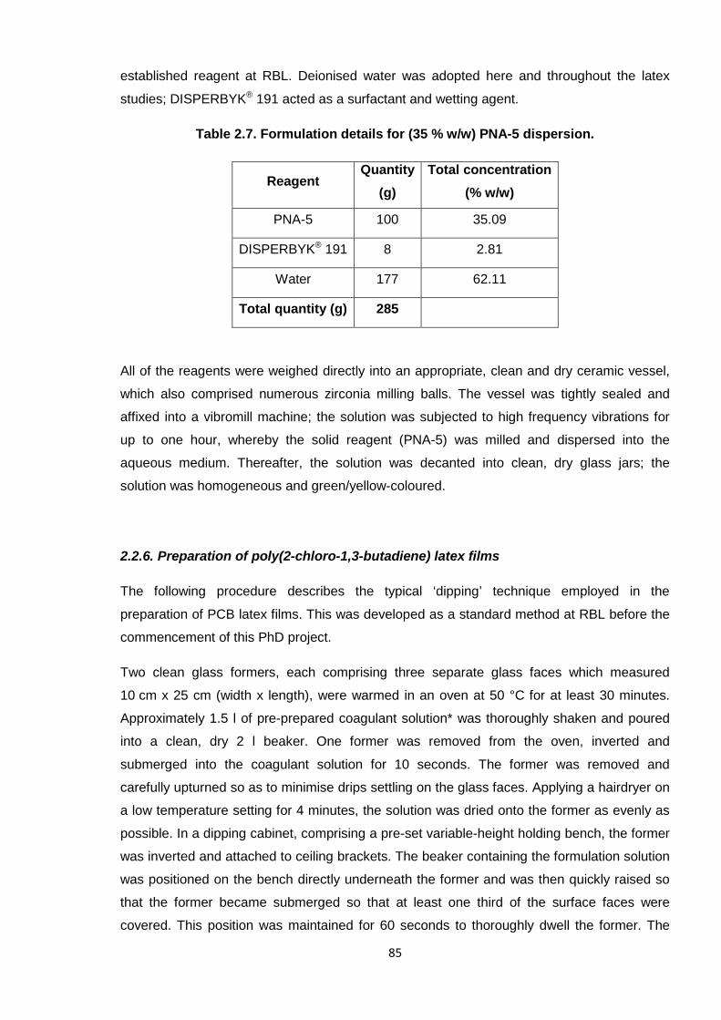
85
established reagent at RBL. Deionised water was adopted here and throughout the latex
studies; DISPERBYK® 191 acted as a surfactant and wetting agent.
Table 2.7. Formulation details for (35 % w/w) PNA-5 dispersion.
ReagentQuantity
(g)
Total concentration
(% w/w)
PNA-5 100 35.09
DISPERBYK® 191 8 2.81
Water 177 62.11
Total quantity (g) 285
All of the reagents were weighed directly into an appropriate, clean and dry ceramic vessel,
which also comprised numerous zirconia milling balls. The vessel was tightly sealed and
affixed into a vibromill machine; the solution was subjected to high frequency vibrations for
up to one hour, whereby the solid reagent (PNA-5) was milled and dispersed into the
aqueous medium. Thereafter, the solution was decanted into clean, dry glass jars; the
solution was homogeneous and green/yellow-coloured.
2.2.6. Preparation of poly(2-chloro-1,3-butadiene) latex films
The following procedure describes the typical ‘dipping’ technique employed in the
preparation of PCB latex films. This was developed as a standard method at RBL before the
commencement of this PhD project.
Two clean glass formers, each comprising three separate glass faces which measured
10 cm x 25 cm (width x length), were warmed in an oven at 50 °C for at least 30 minutes.
Approximately 1.5 l of pre-prepared coagulant solution* was thoroughly shaken and poured
into a clean, dry 2 l beaker. One former was removed from the oven, inverted and
submerged into the coagulant solution for 10 seconds. The former was removed and
carefully upturned so as to minimise drips settling on the glass faces. Applying a hairdryer on
a low temperature setting for 4 minutes, the solution was dried onto the former as evenly as
possible. In a dipping cabinet, comprising a pre-set variable-height holding bench, the former
was inverted and attached to ceiling brackets. The beaker containing the formulation solution
was positioned on the bench directly underneath the former and was then quickly raised so
that the former became submerged so that at least one third of the surface faces were
covered. This position was maintained for 60 seconds to thoroughly dwell the former. The
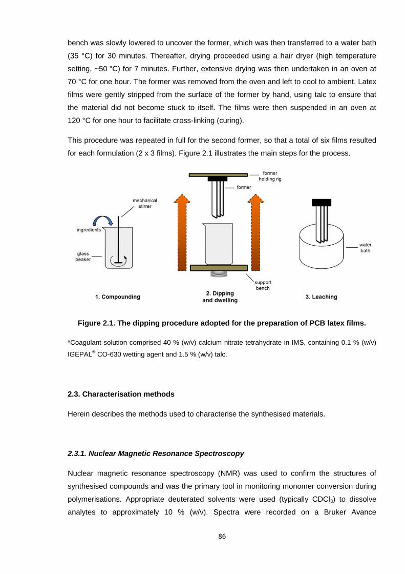
86
bench was slowly lowered to uncover the former, which was then transferred to a water bath
(35 °C) for 30 minutes. Thereafter, drying proceeded using a hair dryer (high temperature
setting, ~50 °C) for 7 minutes. Further, extensive drying was then undertaken in an oven at
70 °C for one hour. The former was removed from the oven and left to cool to ambient. Latex
films were gently stripped from the surface of the former by hand, using talc to ensure that
the material did not become stuck to itself. The films were then suspended in an oven at
120 °C for one hour to facilitate cross-linking (curing).
This procedure was repeated in full for the second former, so that a total of six films resulted
for each formulation (2 x 3 films). Figure 2.1 illustrates the main steps for the process.
Figure 2.1. The dipping procedure adopted for the preparation of PCB latex films.
*Coagulant solution comprised 40 % (w/v) calcium nitrate tetrahydrate in IMS, containing 0.1 % (w/v)
IGEPAL®
CO-630 wetting agent and 1.5 % (w/v) talc.
2.3. Characterisation methods
Herein describes the methods used to characterise the synthesised materials.
2.3.1. Nuclear Magnetic Resonance Spectroscopy
Nuclear magnetic resonance spectroscopy (NMR) was used to confirm the structures of
synthesised compounds and was the primary tool in monitoring monomer conversion during
polymerisations. Appropriate deuterated solvents were used (typically CDCl3) to dissolve
analytes to approximately 10 % (w/v). Spectra were recorded on a Bruker Avance
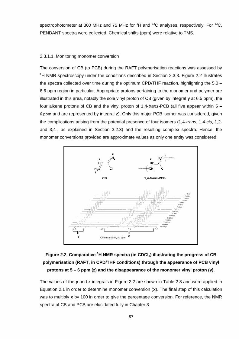
87
spectrophotometer at 300 MHz and 75 MHz for 1H and 13C analyses, respectively. For 13C,
PENDANT spectra were collected. Chemical shifts (ppm) were relative to TMS.
2.3.1.1. Monitoring monomer conversion
The conversion of CB (to PCB) during the RAFT polymerisation reactions was assessed by
1H NMR spectroscopy under the conditions described in Section 2.3.3. Figure 2.2 illustrates
the spectra collected over time during the optimum CPD/THF reaction, highlighting the 5.0 –
6.6 ppm region in particular. Appropriate protons pertaining to the monomer and polymer are
illustrated in this area, notably the sole vinyl proton of CB (given by integral y at 6.5 ppm), the
four alkene protons of CB and the vinyl proton of 1,4-trans-PCB (all five appear within 5 –
6 ppm and are represented by integral z). Only this major PCB isomer was considered, given
the complications arising from the potential presence of four isomers (1,4-trans, 1,4-cis, 1,2-
and 3,4-, as explained in Section 3.2.3) and the resulting complex spectra. Hence, the
monomer conversions provided are approximate values as only one entity was considered.
Figure 2.2. Comparative 1H NMR spectra (in CDCl3) illustrating the progress of CB
polymerisation (RAFT, in CPD/THF conditions) through the appearance of PCB vinyl
protons at 5 – 6 ppm (z) and the disappearance of the monomer vinyl proton (y).
The values of the y and z integrals in Figure 2.2 are shown in Table 2.8 and were applied in
Equation 2.1 in order to determine monomer conversion (x). The final step of this calculation
was to multiply x by 100 in order to give the percentage conversion. For reference, the NMR
spectra of CB and PCB are elucidated fully in Chapter 3.
6.5 6.0 5.5 5.0
Chemical Shift, ppm
T=0
T=3hrs
T=4hrs
T=5hrs
T=6hrs
T=7hrs
T=8hrs
T=9hrs
T=10hrs
CB
z
z
z
y
zy
1,4-trans-PCB
T=11hrs
T=24hrs
T=28hrs
T=30hrs
T=46hrs
T=54hrs
T=7 days
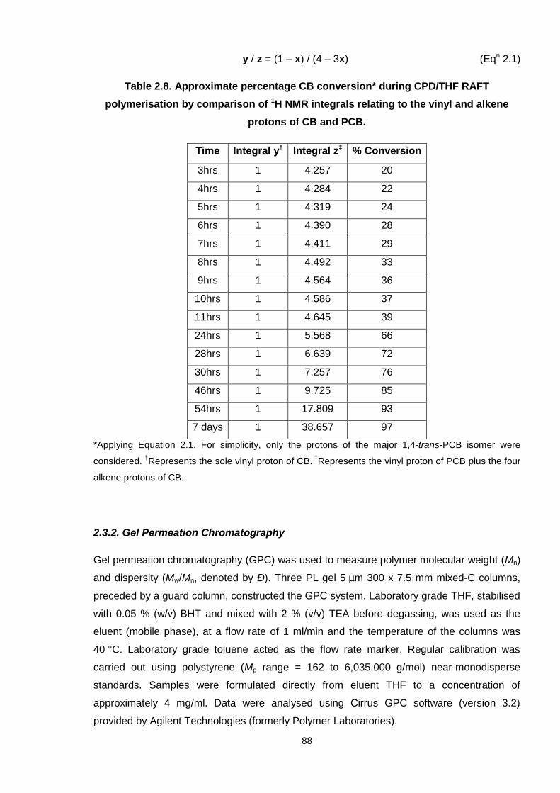
88
y / z = (1 – x) / (4 – 3x) (Eqn 2.1)
Table 2.8. Approximate percentage CB conversion* during CPD/THF RAFT
polymerisation by comparison of 1H NMR integrals relating to the vinyl and alkene
protons of CB and PCB.
Time Integral y† Integral z‡ % Conversion
3hrs 1 4.257 20
4hrs 1 4.284 22
5hrs 1 4.319 24
6hrs 1 4.390 28
7hrs 1 4.411 29
8hrs 1 4.492 33
9hrs 1 4.564 36
10hrs 1 4.586 37
11hrs 1 4.645 39
24hrs 1 5.568 66
28hrs 1 6.639 72
30hrs 1 7.257 76
46hrs 1 9.725 85
54hrs 1 17.809 93
7 days 1 38.657 97
*Applying Equation 2.1. For simplicity, only the protons of the major 1,4-trans-PCB isomer were
considered.†Represents the sole vinyl proton of CB.
‡Represents the vinyl proton of PCB plus the four
alkene protons of CB.
2.3.2. Gel Permeation Chromatography
Gel permeation chromatography (GPC) was used to measure polymer molecular weight (Mn)
and dispersity (Mw/Mn, denoted by Ð). Three PL gel 5 µm 300 x 7.5 mm mixed-C columns,
preceded by a guard column, constructed the GPC system. Laboratory grade THF, stabilised
with 0.05 % (w/v) BHT and mixed with 2 % (v/v) TEA before degassing, was used as the
eluent (mobile phase), at a flow rate of 1 ml/min and the temperature of the columns was
40 °C. Laboratory grade toluene acted as the flow rate marker. Regular calibration was
carried out using polystyrene (Mp range = 162 to 6,035,000 g/mol) near-monodisperse
standards. Samples were formulated directly from eluent THF to a concentration of
approximately 4 mg/ml. Data were analysed using Cirrus GPC software (version 3.2)
provided by Agilent Technologies (formerly Polymer Laboratories).
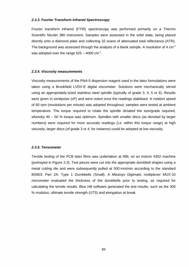
89
2.3.3. Fourier Transform Infrared Spectroscopy
Fourier transform infrared (FTIR) spectroscopy was performed primarily on a Thermo
Scientific Nicolet 380 instrument. Samples were assessed in the solid state, being placed
directly onto a diamond plate and collecting 32 scans of attenuated total reflectance (ATR).
The background was assessed through the analysis of a blank sample. A resolution of 4 cm-1
was adopted over the range 525 – 4000 cm-1.
2.3.4. Viscosity measurements
Viscosity measurements of the PNA-5 dispersion reagent used in the latex formulations were
taken using a Brookfield LVDV-E digital viscometer. Solutions were mechanically stirred
using an appropriately-sized stainless steel spindle (typically of grade 3, 4, 5 or 6). Results
were given in centipoise (cP) and were noted once the readings stabilised. A rotation speed
of 60 rpm (revolutions per minute) was adopted throughout; samples were tested at ambient
temperature. The torque required to rotate the spindle dictated the size/grade required,
whereby 40 – 50 % torque was optimum. Spindles with smaller discs (as denoted by larger
numbers) were required for more accurate readings (i.e. within this torque range) at high
viscosity; larger discs (of grade 3 or 4, for instance) could be adopted at low viscosity.
2.3.5. Tensometer
Tensile testing of the PCB latex films was undertaken at RBL on an Instron 4302 machine
(portrayed in Figure 2.3). Test pieces were cut into the appropriate dumbbell shapes using a
metal cutting die and were subsequently pulled at 500 mm/min according to the standard
BS903: Part 2A: Type 1 Dumbbells (Small). A Mitutoyo Digimatic multiplexer MUX-10
micrometer evaluated the thickness of the dumbbells prior to testing, as required for
calculating the tensile results. Blue Hill software generated the test results, such as the 300
% modulus, ultimate tensile strength (UTS) and elongation at break.
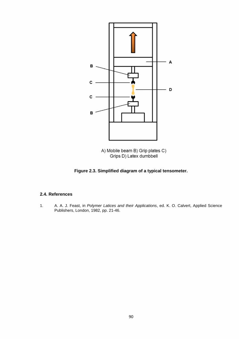
90
Figure 2.3. Simplified diagram of a typical tensometer.
2.4. References
1. A. A. J. Feast, in Polymer Latices and their Applications, ed. K. O. Calvert, Applied SciencePublishers, London, 1982, pp. 21-46.
91
CHAPTER 3
RAFT POLYMERISATION OF
2-CHLORO-1,3-BUTADIENE
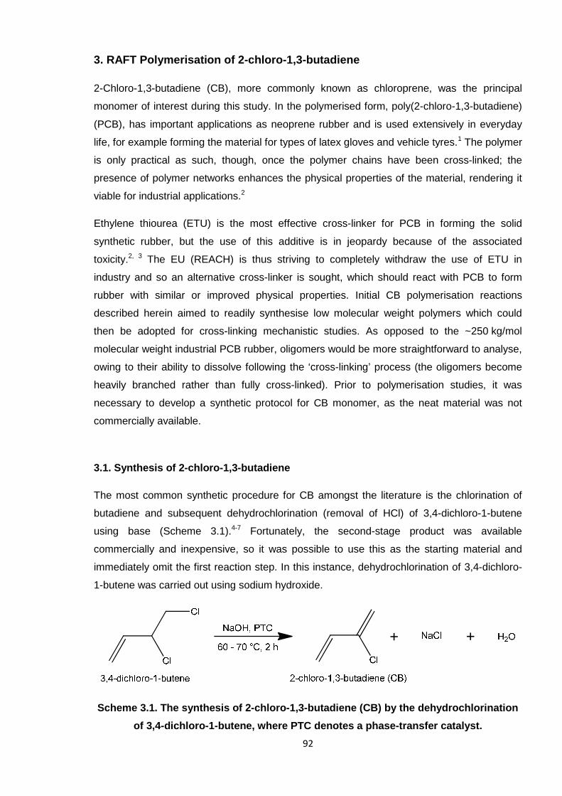
92
3. RAFT Polymerisation of 2-chloro-1,3-butadiene
2-Chloro-1,3-butadiene (CB), more commonly known as chloroprene, was the principal
monomer of interest during this study. In the polymerised form, poly(2-chloro-1,3-butadiene)
(PCB), has important applications as neoprene rubber and is used extensively in everyday
life, for example forming the material for types of latex gloves and vehicle tyres.1 The polymer
is only practical as such, though, once the polymer chains have been cross-linked; the
presence of polymer networks enhances the physical properties of the material, rendering it
viable for industrial applications.2
Ethylene thiourea (ETU) is the most effective cross-linker for PCB in forming the solid
synthetic rubber, but the use of this additive is in jeopardy because of the associated
toxicity.2, 3 The EU (REACH) is thus striving to completely withdraw the use of ETU in
industry and so an alternative cross-linker is sought, which should react with PCB to form
rubber with similar or improved physical properties. Initial CB polymerisation reactions
described herein aimed to readily synthesise low molecular weight polymers which could
then be adopted for cross-linking mechanistic studies. As opposed to the ~250 kg/mol
molecular weight industrial PCB rubber, oligomers would be more straightforward to analyse,
owing to their ability to dissolve following the ‘cross-linking’ process (the oligomers become
heavily branched rather than fully cross-linked). Prior to polymerisation studies, it was
necessary to develop a synthetic protocol for CB monomer, as the neat material was not
commercially available.
3.1. Synthesis of 2-chloro-1,3-butadiene
The most common synthetic procedure for CB amongst the literature is the chlorination of
butadiene and subsequent dehydrochlorination (removal of HCl) of 3,4-dichloro-1-butene
using base (Scheme 3.1).4-7 Fortunately, the second-stage product was available
commercially and inexpensive, so it was possible to use this as the starting material and
immediately omit the first reaction step. In this instance, dehydrochlorination of 3,4-dichloro-
1-butene was carried out using sodium hydroxide.
Scheme 3.1. The synthesis of 2-chloro-1,3-butadiene (CB) by the dehydrochlorination
of 3,4-dichloro-1-butene, where PTC denotes a phase-transfer catalyst.
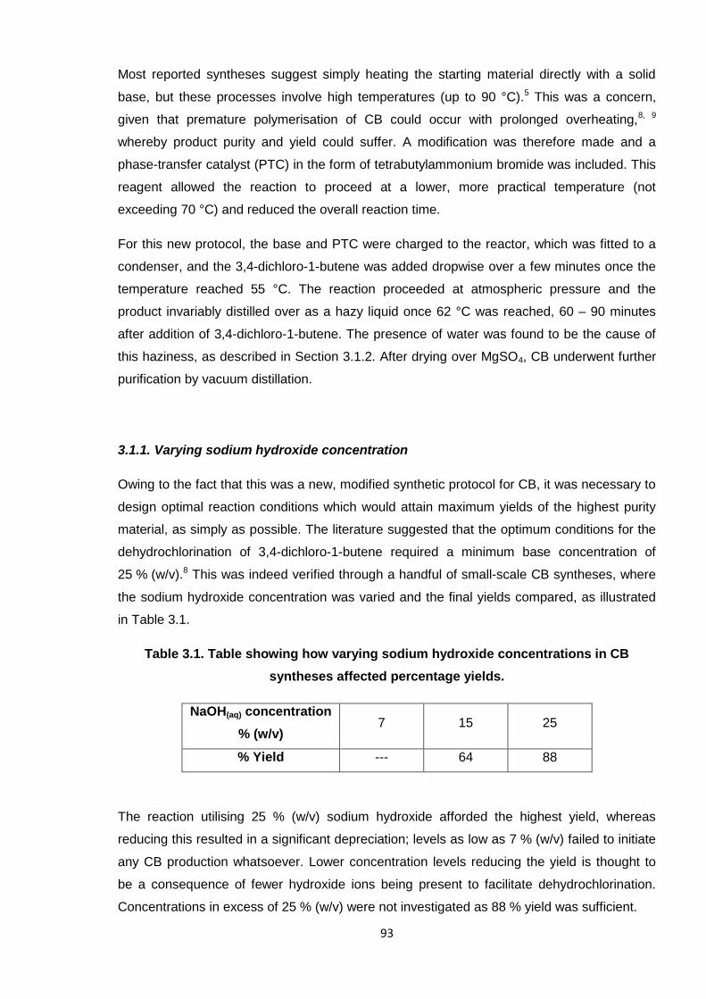
93
Most reported syntheses suggest simply heating the starting material directly with a solid
base, but these processes involve high temperatures (up to 90 °C).5 This was a concern,
given that premature polymerisation of CB could occur with prolonged overheating,8, 9
whereby product purity and yield could suffer. A modification was therefore made and a
phase-transfer catalyst (PTC) in the form of tetrabutylammonium bromide was included. This
reagent allowed the reaction to proceed at a lower, more practical temperature (not
exceeding 70 °C) and reduced the overall reaction time.
For this new protocol, the base and PTC were charged to the reactor, which was fitted to a
condenser, and the 3,4-dichloro-1-butene was added dropwise over a few minutes once the
temperature reached 55 °C. The reaction proceeded at atmospheric pressure and the
product invariably distilled over as a hazy liquid once 62 °C was reached, 60 – 90 minutes
after addition of 3,4-dichloro-1-butene. The presence of water was found to be the cause of
this haziness, as described in Section 3.1.2. After drying over MgSO4, CB underwent further
purification by vacuum distillation.
3.1.1. Varying sodium hydroxide concentration
Owing to the fact that this was a new, modified synthetic protocol for CB, it was necessary to
design optimal reaction conditions which would attain maximum yields of the highest purity
material, as simply as possible. The literature suggested that the optimum conditions for the
dehydrochlorination of 3,4-dichloro-1-butene required a minimum base concentration of
25 % (w/v).8 This was indeed verified through a handful of small-scale CB syntheses, where
the sodium hydroxide concentration was varied and the final yields compared, as illustrated
in Table 3.1.
Table 3.1. Table showing how varying sodium hydroxide concentrations in CB
syntheses affected percentage yields.
NaOH(aq) concentration
% (w/v)7 15 25
% Yield --- 64 88
The reaction utilising 25 % (w/v) sodium hydroxide afforded the highest yield, whereas
reducing this resulted in a significant depreciation; levels as low as 7 % (w/v) failed to initiate
any CB production whatsoever. Lower concentration levels reducing the yield is thought to
be a consequence of fewer hydroxide ions being present to facilitate dehydrochlorination.
Concentrations in excess of 25 % (w/v) were not investigated as 88 % yield was sufficient.
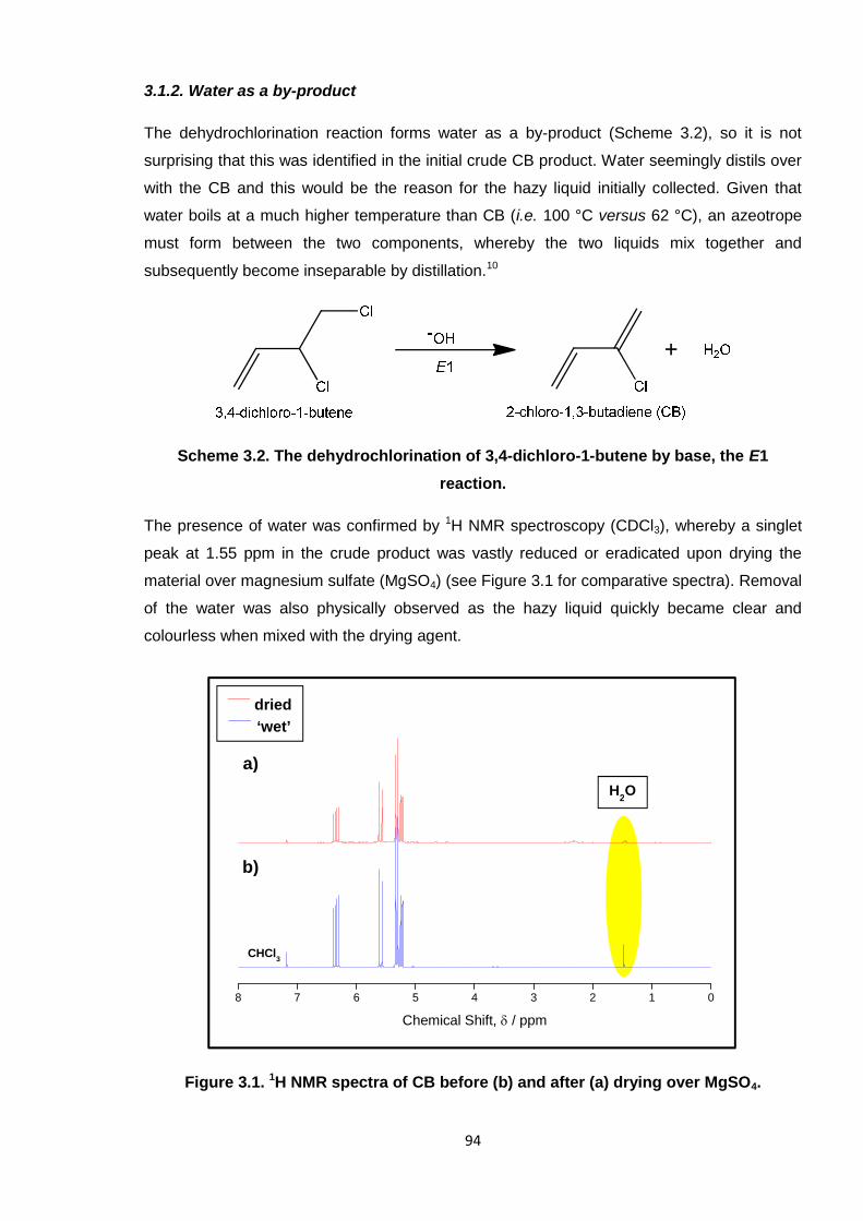
94
3.1.2. Water as a by-product
The dehydrochlorination reaction forms water as a by-product (Scheme 3.2), so it is not
surprising that this was identified in the initial crude CB product. Water seemingly distils over
with the CB and this would be the reason for the hazy liquid initially collected. Given that
water boils at a much higher temperature than CB (i.e. 100 °C versus 62 °C), an azeotrope
must form between the two components, whereby the two liquids mix together and
subsequently become inseparable by distillation.10
Scheme 3.2. The dehydrochlorination of 3,4-dichloro-1-butene by base, the E1
reaction.
The presence of water was confirmed by 1H NMR spectroscopy (CDCl3), whereby a singlet
peak at 1.55 ppm in the crude product was vastly reduced or eradicated upon drying the
material over magnesium sulfate (MgSO4) (see Figure 3.1 for comparative spectra). Removal
of the water was also physically observed as the hazy liquid quickly became clear and
colourless when mixed with the drying agent.
Figure 3.1. 1H NMR spectra of CB before (b) and after (a) drying over MgSO4.
8 7 6 5 4 3 2 1 0
Chemical Shift, / ppm
a)
b)
H2O
CHCl3
____dried
____‘wet’
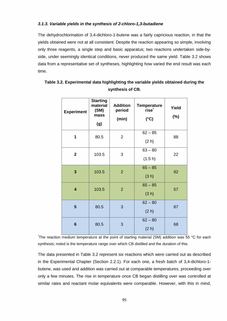
95
3.1.3. Variable yields in the synthesis of 2-chloro-1,3-butadiene
The dehydrochlorination of 3,4-dichloro-1-butene was a fairly capricious reaction, in that the
yields obtained were not at all consistent. Despite the reaction appearing so simple, involving
only three reagents, a single step and basic apparatus; two reactions undertaken side-by-
side, under seemingly identical conditions, never produced the same yield. Table 3.2 shows
data from a representative set of syntheses, highlighting how varied the end result was each
time.
Table 3.2. Experimental data highlighting the variable yields obtained during the
synthesis of CB.
Experiment
Startingmaterial
(SM)mass
(g)
Additionperiod
(min)
Temperaturerise*
(°C)
Yield
(%)
1 80.5 262 – 85
(2 h)88
2 103.5 363 – 80
(1.5 h)22
3 103.5 265 – 85
(3 h)92
4 103.5 265 – 85
(3 h)57
5 80.5 362 – 80
(2 h)87
6 80.5 362 – 80
(2 h)68
*The reaction medium temperature at the point of starting material (SM) addition was 55 °C for each
synthesis; noted is the temperature range over which CB distilled and the duration of this.
The data presented in Table 3.2 represent six reactions which were carried out as described
in the Experimental Chapter (Section 2.2.1). For each one, a fresh batch of 3,4-dichloro-1-
butene, was used and addition was carried out at comparable temperatures, proceeding over
only a few minutes. The rise in temperature once CB began distilling over was controlled at
similar rates and reactant molar equivalents were comparable. However, with this in mind,
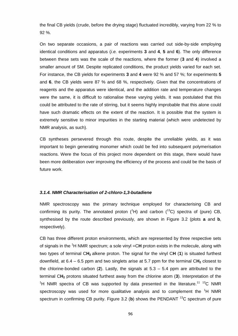
96
the final CB yields (crude, before the drying stage) fluctuated incredibly, varying from 22 % to
92 %.
On two separate occasions, a pair of reactions was carried out side-by-side employing
identical conditions and apparatus (i.e. experiments 3 and 4, 5 and 6). The only difference
between these sets was the scale of the reactions, where the former (3 and 4) involved a
smaller amount of SM. Despite replicated conditions, the product yields varied for each set.
For instance, the CB yields for experiments 3 and 4 were 92 % and 57 %; for experiments 5
and 6, the CB yields were 87 % and 68 %, respectively. Given that the concentrations of
reagents and the apparatus were identical, and the addition rate and temperature changes
were the same, it is difficult to rationalise these varying yields. It was postulated that this
could be attributed to the rate of stirring, but it seems highly improbable that this alone could
have such dramatic effects on the extent of the reaction. It is possible that the system is
extremely sensitive to minor impurities in the starting material (which were undetected by
NMR analysis, as such).
CB syntheses persevered through this route, despite the unreliable yields, as it was
important to begin generating monomer which could be fed into subsequent polymerisation
reactions. Were the focus of this project more dependent on this stage, there would have
been more deliberation over improving the efficiency of the process and could be the basis of
future work.
3.1.4. NMR Characterisation of 2-chloro-1,3-butadiene
NMR spectroscopy was the primary technique employed for characterising CB and
confirming its purity. The annotated proton (1H) and carbon (13C) spectra of (pure) CB,
synthesised by the route described previously, are shown in Figure 3.2 (plots a and b,
respectively).
CB has three different proton environments, which are represented by three respective sets
of signals in the 1H NMR spectrum; a sole vinyl =CH proton exists in the molecule, along with
two types of terminal CH2 alkene proton. The signal for the vinyl CH (1) is situated furthest
downfield, at 6.4 – 6.5 ppm and two singlets arise at 5.7 ppm for the terminal CH2 closest to
the chlorine-bonded carbon (2). Lastly, the signals at 5.3 – 5.4 ppm are attributed to the
terminal CH2 protons situated furthest away from the chlorine atom (3). Interpretation of the
1H NMR spectra of CB was supported by data presented in the literature.11 13C NMR
spectroscopy was used for more qualitative analysis and to complement the 1H NMR
spectrum in confirming CB purity. Figure 3.2 (b) shows the PENDANT 13C spectrum of pure
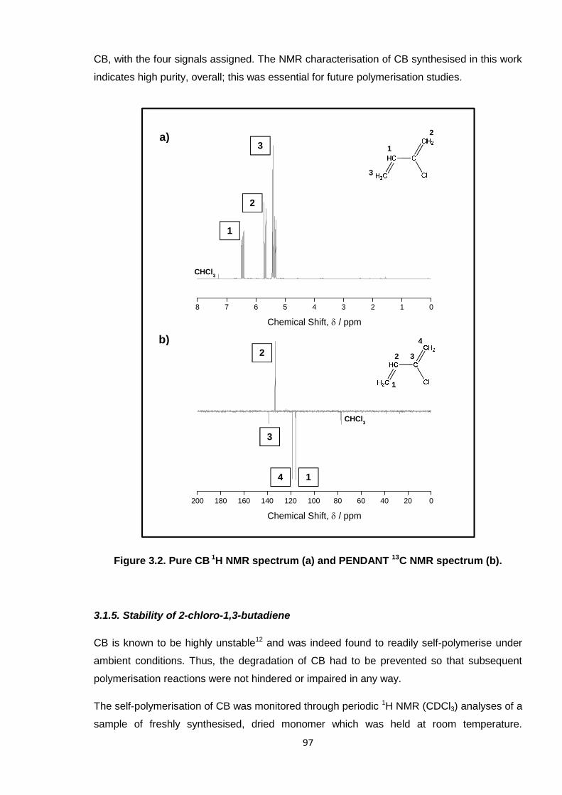
97
CB, with the four signals assigned. The NMR characterisation of CB synthesised in this work
indicates high purity, overall; this was essential for future polymerisation studies.
Figure 3.2. Pure CB 1H NMR spectrum (a) and PENDANT 13C NMR spectrum (b).
3.1.5. Stability of 2-chloro-1,3-butadiene
CB is known to be highly unstable12 and was indeed found to readily self-polymerise under
ambient conditions. Thus, the degradation of CB had to be prevented so that subsequent
polymerisation reactions were not hindered or impaired in any way.
The self-polymerisation of CB was monitored through periodic 1H NMR (CDCl3) analyses of a
sample of freshly synthesised, dried monomer which was held at room temperature.
8 7 6 5 4 3 2 1 0
Chemical Shift, / ppm
200 180 160 140 120 100 80 60 40 20 0
Chemical Shift, / ppm
1
2
3
4
4
3
2
1
CHCl3
3
3
2
2
1
1
CHCl3
a)
b)
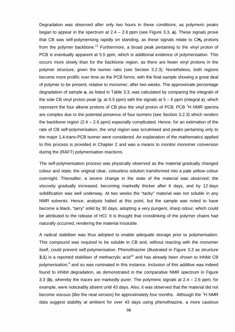
98
Degradation was observed after only two hours in these conditions, as polymeric peaks
began to appear in the spectrum at 2.4 – 2.6 ppm (see Figure 3.3, a). These signals prove
that CB was self-polymerising rapidly on standing, as these signals relate to CH2 protons
from the polymer backbone.13 Furthermore, a broad peak pertaining to the vinyl proton of
PCB is eventually apparent at 5.5 ppm, which is additional evidence of polymerisation. This
occurs more slowly than for the backbone region, as there are fewer vinyl protons in the
polymer structure, given the isomer ratio (see Section 3.2.3). Nonetheless, both regions
become more prolific over time as the PCB forms, with the final sample showing a great deal
of polymer to be present, relative to monomer, after two weeks. The approximate percentage
degradation of sample a, as listed in Table 3.3, was calculated by comparing the integrals of
the sole CB vinyl proton peak (y, at 6.5 ppm) with the signals at 5 – 6 ppm (integral z), which
represent the four alkene protons of CB plus the vinyl proton of PCB. PCB 1H NMR spectra
are complex due to the potential presence of four isomers (see Section 3.2.3) which renders
the backbone region (2.4 – 2.6 ppm) especially complicated. Hence, for an estimation of the
rate of CB self-polymerisation, the vinyl region was scrutinised and peaks pertaining only to
the major 1,4-trans-PCB isomer were considered. An explanation of the mathematics applied
to this process is provided in Chapter 2 and was a means to monitor monomer conversion
during the (RAFT) polymerisation reactions.
The self-polymerisation process was physically observed as the material gradually changed
colour and state; the original clear, colourless solution transformed into a pale yellow colour
overnight. Thereafter, a severe change in the state of the material was observed; the
viscosity gradually increased, becoming markedly thicker after 6 days, and by 12 days
solidification was well underway. At two weeks the “tacky” material was not soluble in any
NMR solvents. Hence, analysis halted at this point, but the sample was noted to have
become a black, “tarry” solid by 30 days, adopting a very pungent, sharp odour, which could
be attributed to the release of HCl. It is thought that crosslinking of the polymer chains had
naturally occurred, rendering the material insoluble.
A radical stabiliser was thus adopted to enable adequate storage prior to polymerisation.
This compound was required to be soluble in CB and, without reacting with the monomer
itself, could prevent self-polymerisation. Phenothiazine (illustrated in Figure 3.3 as structure
3.1) is a reported stabiliser of methacrylic acid14 and has already been shown to inhibit CB
polymerisation,6 and so was ruminated in this instance. Inclusion of this additive was indeed
found to inhibit degradation, as demonstrated in the comparative NMR spectrum in Figure
3.3 (b), whereby the traces are markedly purer. The polymeric signals at 2.4 – 2.6 ppm, for
example, were noticeably absent until 43 days. Also, it was observed that the material did not
become viscous (like the neat version) for approximately four months. Although the 1H NMR
data suggest stability at ambient for over 43 days using phenothiazine, a more cautious
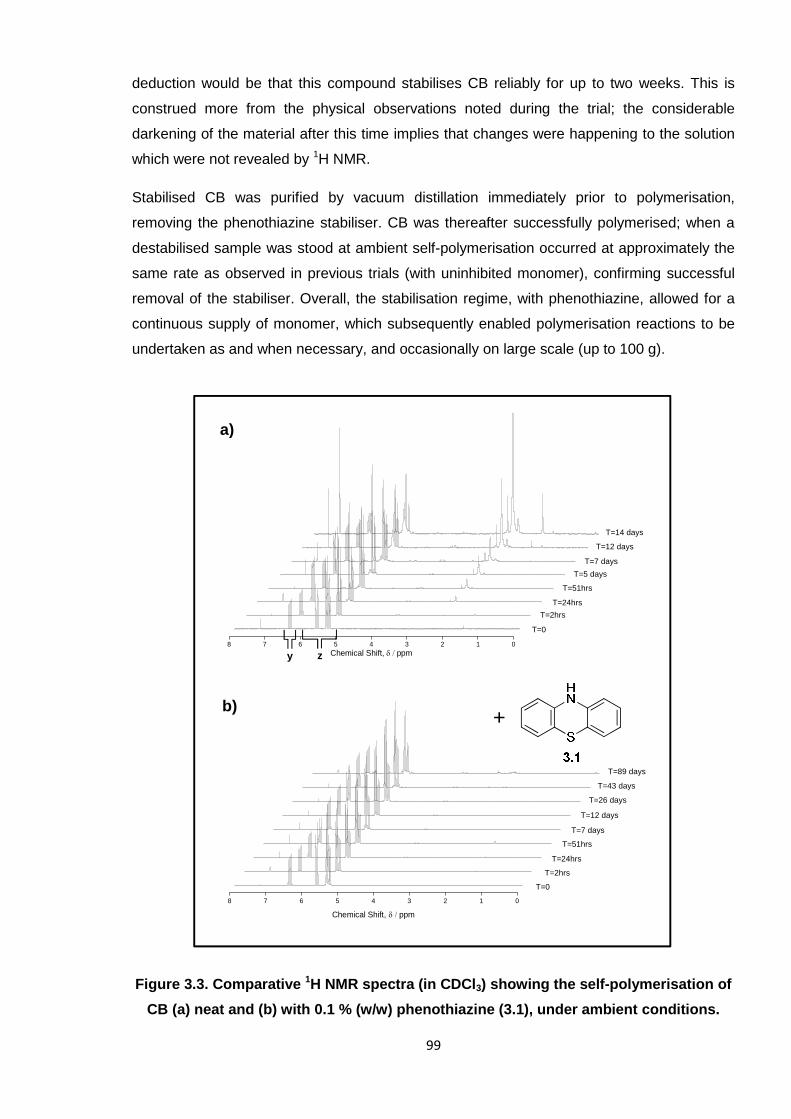
99
deduction would be that this compound stabilises CB reliably for up to two weeks. This is
construed more from the physical observations noted during the trial; the considerable
darkening of the material after this time implies that changes were happening to the solution
which were not revealed by 1H NMR.
Stabilised CB was purified by vacuum distillation immediately prior to polymerisation,
removing the phenothiazine stabiliser. CB was thereafter successfully polymerised; when a
destabilised sample was stood at ambient self-polymerisation occurred at approximately the
same rate as observed in previous trials (with uninhibited monomer), confirming successful
removal of the stabiliser. Overall, the stabilisation regime, with phenothiazine, allowed for a
continuous supply of monomer, which subsequently enabled polymerisation reactions to be
undertaken as and when necessary, and occasionally on large scale (up to 100 g).
Figure 3.3. Comparative 1H NMR spectra (in CDCl3) showing the self-polymerisation of
CB (a) neat and (b) with 0.1 % (w/w) phenothiazine (3.1), under ambient conditions.
a)
b)
8 7 6 5 4 3 2 1 0
Chemical Shift, ppm
8 7 6 5 4 3 2 1 0
Chemical Shift, ppm
T=14 days
T=12 days
T=7 days
T=5 days
T=51hrs
T=24hrs
T=2hrs
T=0
T=89 days
T=43 days
T=26 days
T=12 days
T=7 days
T=51hrs
T=24hrs
T=2hrs
T=0
zy
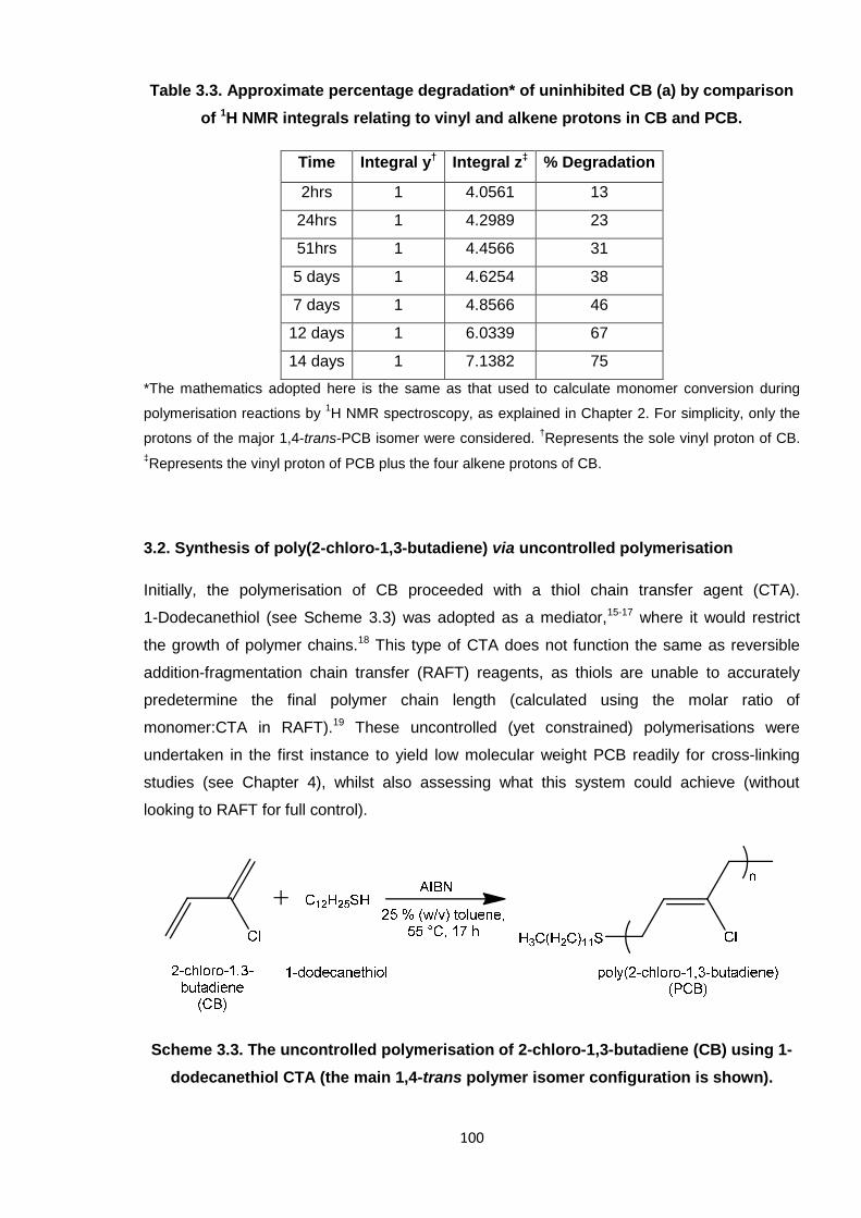
100
Table 3.3. Approximate percentage degradation* of uninhibited CB (a) by comparison
of 1H NMR integrals relating to vinyl and alkene protons in CB and PCB.
Time Integral y† Integral z‡ % Degradation
2hrs 1 4.0561 13
24hrs 1 4.2989 23
51hrs 1 4.4566 31
5 days 1 4.6254 38
7 days 1 4.8566 46
12 days 1 6.0339 67
14 days 1 7.1382 75
*The mathematics adopted here is the same as that used to calculate monomer conversion during
polymerisation reactions by1H NMR spectroscopy, as explained in Chapter 2. For simplicity, only the
protons of the major 1,4-trans-PCB isomer were considered.†Represents the sole vinyl proton of CB.
‡Represents the vinyl proton of PCB plus the four alkene protons of CB.
3.2. Synthesis of poly(2-chloro-1,3-butadiene) via uncontrolled polymerisation
Initially, the polymerisation of CB proceeded with a thiol chain transfer agent (CTA).
1-Dodecanethiol (see Scheme 3.3) was adopted as a mediator,15-17 where it would restrict
the growth of polymer chains.18 This type of CTA does not function the same as reversible
addition-fragmentation chain transfer (RAFT) reagents, as thiols are unable to accurately
predetermine the final polymer chain length (calculated using the molar ratio of
monomer:CTA in RAFT).19 These uncontrolled (yet constrained) polymerisations were
undertaken in the first instance to yield low molecular weight PCB readily for cross-linking
studies (see Chapter 4), whilst also assessing what this system could achieve (without
looking to RAFT for full control).
Scheme 3.3. The uncontrolled polymerisation of 2-chloro-1,3-butadiene (CB) using 1-
dodecanethiol CTA (the main 1,4-trans polymer isomer configuration is shown).
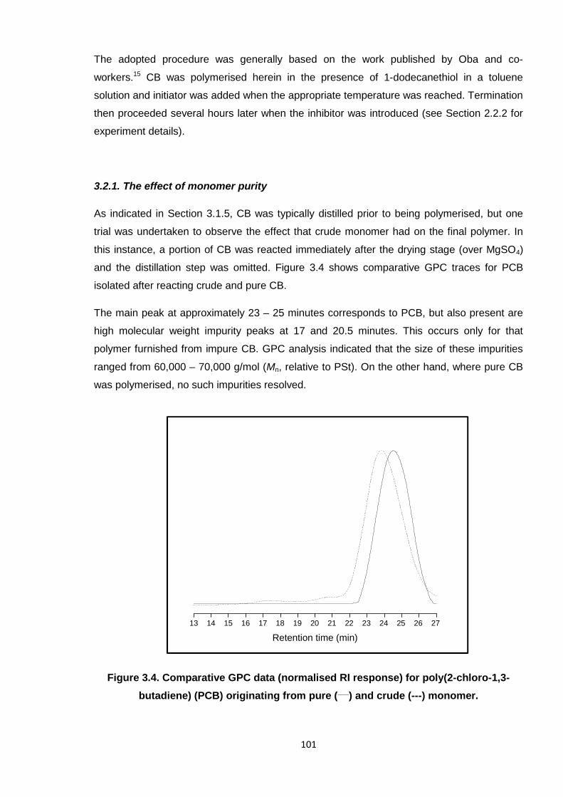
101
The adopted procedure was generally based on the work published by Oba and co-
workers.15 CB was polymerised herein in the presence of 1-dodecanethiol in a toluene
solution and initiator was added when the appropriate temperature was reached. Termination
then proceeded several hours later when the inhibitor was introduced (see Section 2.2.2 for
experiment details).
3.2.1. The effect of monomer purity
As indicated in Section 3.1.5, CB was typically distilled prior to being polymerised, but one
trial was undertaken to observe the effect that crude monomer had on the final polymer. In
this instance, a portion of CB was reacted immediately after the drying stage (over MgSO4)
and the distillation step was omitted. Figure 3.4 shows comparative GPC traces for PCB
isolated after reacting crude and pure CB.
The main peak at approximately 23 – 25 minutes corresponds to PCB, but also present are
high molecular weight impurity peaks at 17 and 20.5 minutes. This occurs only for that
polymer furnished from impure CB. GPC analysis indicated that the size of these impurities
ranged from 60,000 – 70,000 g/mol (Mn, relative to PSt). On the other hand, where pure CB
was polymerised, no such impurities resolved.
Figure 3.4. Comparative GPC data (normalised RI response) for poly(2-chloro-1,3-
butadiene) (PCB) originating from pure (___) and crude (---) monomer.
13 14 15 16 17 18 19 20 21 22 23 24 25 26 27
Retention time (min)
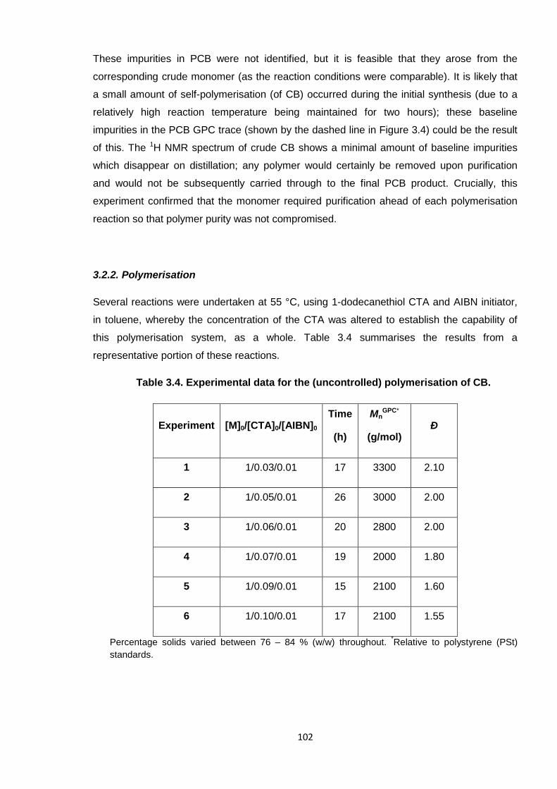
102
These impurities in PCB were not identified, but it is feasible that they arose from the
corresponding crude monomer (as the reaction conditions were comparable). It is likely that
a small amount of self-polymerisation (of CB) occurred during the initial synthesis (due to a
relatively high reaction temperature being maintained for two hours); these baseline
impurities in the PCB GPC trace (shown by the dashed line in Figure 3.4) could be the result
of this. The 1H NMR spectrum of crude CB shows a minimal amount of baseline impurities
which disappear on distillation; any polymer would certainly be removed upon purification
and would not be subsequently carried through to the final PCB product. Crucially, this
experiment confirmed that the monomer required purification ahead of each polymerisation
reaction so that polymer purity was not compromised.
3.2.2. Polymerisation
Several reactions were undertaken at 55 °C, using 1-dodecanethiol CTA and AIBN initiator,
in toluene, whereby the concentration of the CTA was altered to establish the capability of
this polymerisation system, as a whole. Table 3.4 summarises the results from a
representative portion of these reactions.
Table 3.4. Experimental data for the (uncontrolled) polymerisation of CB.
Experiment [M]0/[CTA]0/[AIBN]0
Time
(h)
MnGPC*
(g/mol)Ð
1 1/0.03/0.01 17 3300 2.10
2 1/0.05/0.01 26 3000 2.00
3 1/0.06/0.01 20 2800 2.00
4 1/0.07/0.01 19 2000 1.80
5 1/0.09/0.01 15 2100 1.60
6 1/0.10/0.01 17 2100 1.55
Percentage solids varied between 76 – 84 % (w/w) throughout.*Relative to polystyrene (PSt)
standards.
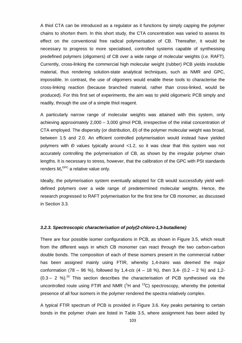
103
A thiol CTA can be introduced as a regulator as it functions by simply capping the polymer
chains to shorten them. In this short study, the CTA concentration was varied to assess its
effect on the conventional free radical polymerisation of CB. Thereafter, it would be
necessary to progress to more specialised, controlled systems capable of synthesising
predefined polymers (oligomers) of CB over a wide range of molecular weights (i.e. RAFT).
Currently, cross-linking the commercial high molecular weight (rubber) PCB yields insoluble
material, thus rendering solution-state analytical techniques, such as NMR and GPC,
impossible. In contrast, the use of oligomers would enable these tools to characterise the
cross-linking reaction (because branched material, rather than cross-linked, would be
produced). For this first set of experiments, the aim was to yield oligomeric PCB simply and
readily, through the use of a simple thiol reagent.
A particularly narrow range of molecular weights was attained with this system, only
achieving approximately 2,000 – 3,000 g/mol PCB, irrespective of the initial concentration of
CTA employed. The dispersity (or distribution, Ð) of the polymer molecular weight was broad,
between 1.5 and 2.0. An efficient controlled polymerisation would instead have yielded
polymers with Ð values typically around <1.2, so it was clear that this system was not
accurately controlling the polymerisation of CB, as shown by the irregular polymer chain
lengths. It is necessary to stress, however, that the calibration of the GPC with PSt standards
renders MnGPC a relative value only.
Ideally, the polymerisation system eventually adopted for CB would successfully yield well-
defined polymers over a wide range of predetermined molecular weights. Hence, the
research progressed to RAFT polymerisation for the first time for CB monomer, as discussed
in Section 3.3.
3.2.3. Spectroscopic characterisation of poly(2-chloro-1,3-butadiene)
There are four possible isomer configurations in PCB, as shown in Figure 3.5, which result
from the different ways in which CB monomer can react through the two carbon-carbon
double bonds. The composition of each of these isomers present in the commercial rubber
has been assigned mainly using FTIR, whereby 1,4-trans was deemed the major
conformation (78 – 96 %), followed by 1,4-cis (4 – 18 %), then 3,4- (0.2 – 2 %) and 1,2-
(0.3 – 2 %).20 This section describes the characterisation of PCB synthesised via the
uncontrolled route using FTIR and NMR (1H and 13C) spectroscopy, whereby the potential
presence of all four isomers in the polymer rendered the spectra relatively complex.
A typical FTIR spectrum of PCB is provided in Figure 3.6. Key peaks pertaining to certain
bonds in the polymer chain are listed in Table 3.5, where assignment has been aided by
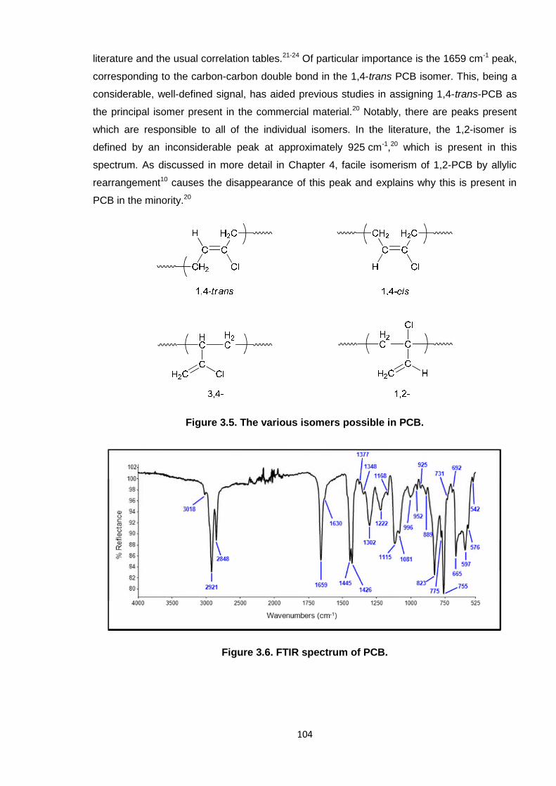
104
literature and the usual correlation tables.21-24 Of particular importance is the 1659 cm-1 peak,
corresponding to the carbon-carbon double bond in the 1,4-trans PCB isomer. This, being a
considerable, well-defined signal, has aided previous studies in assigning 1,4-trans-PCB as
the principal isomer present in the commercial material.20 Notably, there are peaks present
which are responsible to all of the individual isomers. In the literature, the 1,2-isomer is
defined by an inconsiderable peak at approximately 925 cm-1,20 which is present in this
spectrum. As discussed in more detail in Chapter 4, facile isomerism of 1,2-PCB by allylic
rearrangement10 causes the disappearance of this peak and explains why this is present in
PCB in the minority.20
Figure 3.5. The various isomers possible in PCB.
Figure 3.6. FTIR spectrum of PCB.
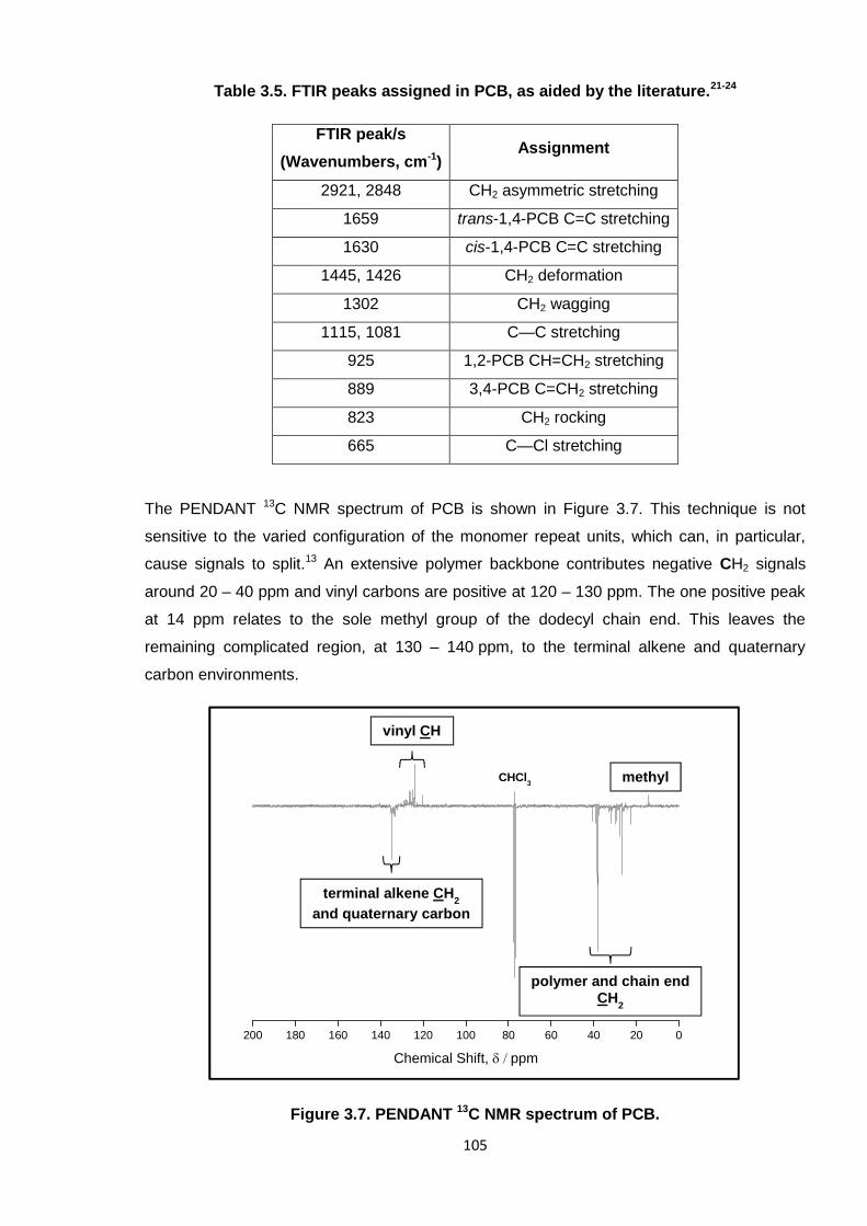
105
Table 3.5. FTIR peaks assigned in PCB, as aided by the literature.21-24
FTIR peak/s
(Wavenumbers, cm-1)Assignment
2921, 2848 CH2 asymmetric stretching
1659 trans-1,4-PCB C=C stretching
1630 cis-1,4-PCB C=C stretching
1445, 1426 CH2 deformation
1302 CH2 wagging
1115, 1081 C—C stretching
925 1,2-PCB CH=CH2 stretching
889 3,4-PCB C=CH2 stretching
823 CH2 rocking
665 C—Cl stretching
The PENDANT 13C NMR spectrum of PCB is shown in Figure 3.7. This technique is not
sensitive to the varied configuration of the monomer repeat units, which can, in particular,
cause signals to split.13 An extensive polymer backbone contributes negative CH2 signals
around 20 – 40 ppm and vinyl carbons are positive at 120 – 130 ppm. The one positive peak
at 14 ppm relates to the sole methyl group of the dodecyl chain end. This leaves the
remaining complicated region, at 130 – 140 ppm, to the terminal alkene and quaternary
carbon environments.
Figure 3.7. PENDANT 13C NMR spectrum of PCB.
200 180 160 140 120 100 80 60 40 20 0
Chemical Shift, ppm
polymer and chain endCH
2
methylCHCl3
vinyl CH
terminal alkene CH2
and quaternary carbon
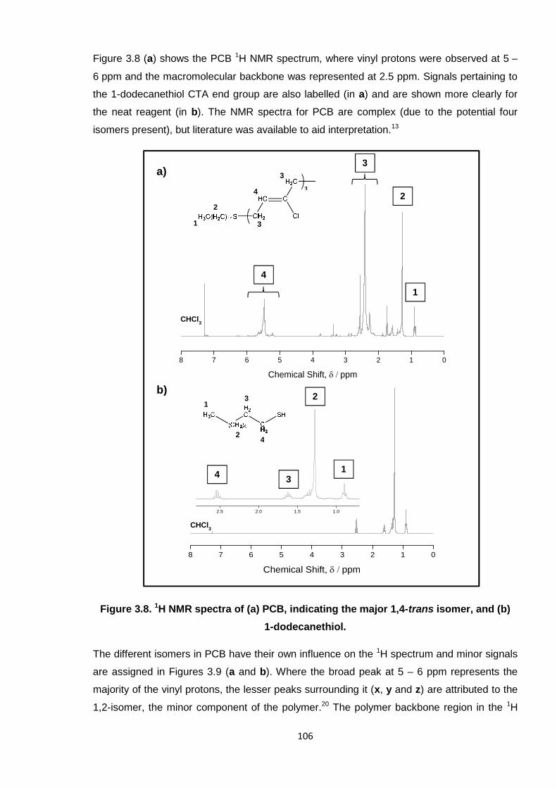
106
Figure 3.8 (a) shows the PCB 1H NMR spectrum, where vinyl protons were observed at 5 –
6 ppm and the macromolecular backbone was represented at 2.5 ppm. Signals pertaining to
the 1-dodecanethiol CTA end group are also labelled (in a) and are shown more clearly for
the neat reagent (in b). The NMR spectra for PCB are complex (due to the potential four
isomers present), but literature was available to aid interpretation.13
Figure 3.8. 1H NMR spectra of (a) PCB, indicating the major 1,4-trans isomer, and (b)
1-dodecanethiol.
The different isomers in PCB have their own influence on the 1H spectrum and minor signals
are assigned in Figures 3.9 (a and b). Where the broad peak at 5 – 6 ppm represents the
majority of the vinyl protons, the lesser peaks surrounding it (x, y and z) are attributed to the
1,2-isomer, the minor component of the polymer.20 The polymer backbone region in the 1H
8 7 6 5 4 3 2 1 0
Chemical Shift, ppm
8 7 6 5 4 3 2 1 0
Chemical Shift, ppm
2.5 2.0 1.5 1.0
3
2
1
4
a)
b)
2
1
2
13
4
3
3
CHCl3
CHCl3
4
1
2
3
4
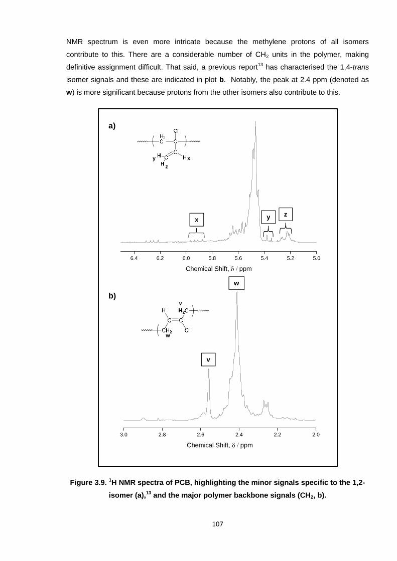
107
NMR spectrum is even more intricate because the methylene protons of all isomers
contribute to this. There are a considerable number of CH2 units in the polymer, making
definitive assignment difficult. That said, a previous report13 has characterised the 1,4-trans
isomer signals and these are indicated in plot b. Notably, the peak at 2.4 ppm (denoted as
w) is more significant because protons from the other isomers also contribute to this.
Figure 3.9. 1H NMR spectra of PCB, highlighting the minor signals specific to the 1,2-
isomer (a),13 and the major polymer backbone signals (CH2, b).
6.4 6.2 6.0 5.8 5.6 5.4 5.2 5.0
Chemical Shift, ppm
3.0 2.8 2.6 2.4 2.2 2.0
Chemical Shift, ppm
v
w
xy
z
a)
b)
x y z
w
v
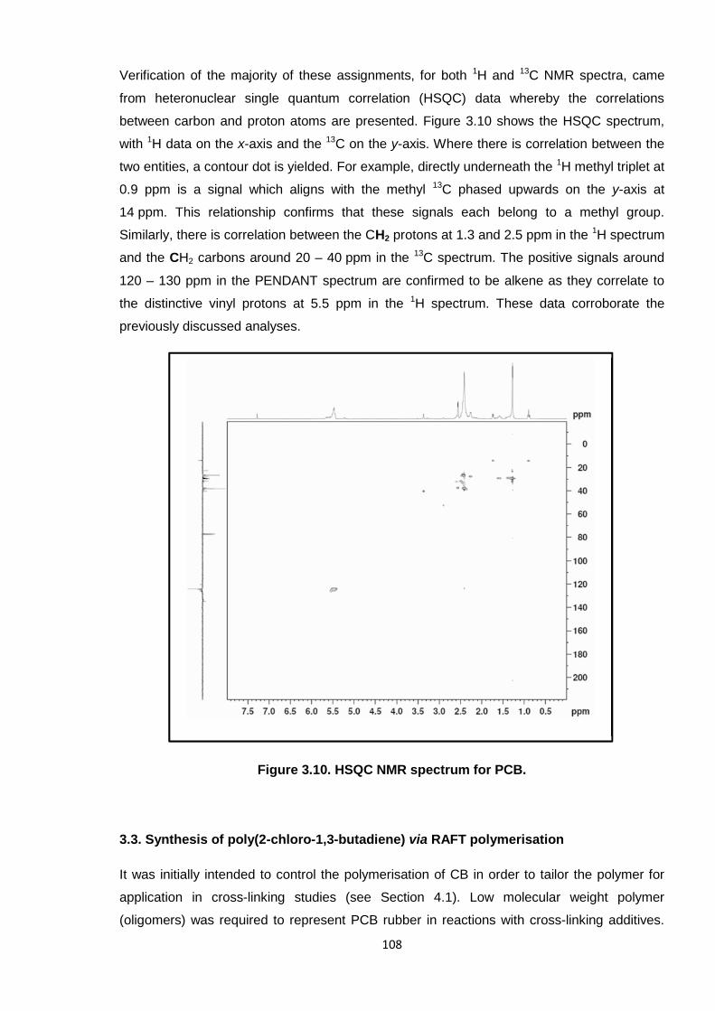
108
Verification of the majority of these assignments, for both 1H and 13C NMR spectra, came
from heteronuclear single quantum correlation (HSQC) data whereby the correlations
between carbon and proton atoms are presented. Figure 3.10 shows the HSQC spectrum,
with 1H data on the x-axis and the 13C on the y-axis. Where there is correlation between the
two entities, a contour dot is yielded. For example, directly underneath the 1H methyl triplet at
0.9 ppm is a signal which aligns with the methyl 13C phased upwards on the y-axis at
14 ppm. This relationship confirms that these signals each belong to a methyl group.
Similarly, there is correlation between the CH2 protons at 1.3 and 2.5 ppm in the 1H spectrum
and the CH2 carbons around 20 – 40 ppm in the 13C spectrum. The positive signals around
120 – 130 ppm in the PENDANT spectrum are confirmed to be alkene as they correlate to
the distinctive vinyl protons at 5.5 ppm in the 1H spectrum. These data corroborate the
previously discussed analyses.
Figure 3.10. HSQC NMR spectrum for PCB.
3.3. Synthesis of poly(2-chloro-1,3-butadiene) via RAFT polymerisation
It was initially intended to control the polymerisation of CB in order to tailor the polymer for
application in cross-linking studies (see Section 4.1). Low molecular weight polymer
(oligomers) was required to represent PCB rubber in reactions with cross-linking additives.
109
PCB rubber is a high molecular weight polymer, which is difficult to process and is rendered
insoluble once cross-linked. As a result, monitoring the cross-linking is extremely challenging
as the standard analytical techniques often adopted, such as NMR spectroscopy, are not
possible. It is known, for instance, that PCB rubber swells rather than dissolves in typical
NMR solvents like CDCl3.10 Hence, the analytical methods were limited solely to FTIR
spectroscopy (solid-state NMR was unavailable at sufficiently high resolution). Thus, lower
molecular weight oligomers were considered because, when mixed with cross-linking
additives, they would become branched (rather than fully cross-linked) and thus remain
soluble, which would, in turn, render other analyses possible.
PCB is synthesised in industry by conventional free radical polymerisation using a thiol chain
transfer agent (CTA) to regulate the molecular weight (see Section 3.2).15 Controlling the
synthesis of PCB using reversible addition-fragmentation chain transfer (RAFT) technology
had, at the time of these studies, still eluded polymer chemists, in that no reports of such
existed. The only publication involving this monomer in a controlled-radical reaction adopted
NMP, where CB was copolymerised with a phosphonated diene.25
Controlled polymerisation techniques, such as ATRP, NMP and RAFT, enable a degree of
control to be asserted over the polymer molecular weight, molecular weight distribution
(Mw/Mn, dispersity, Ð) and macromolecular architecture, which conventional free radical
processes do not.26 The RAFT technique is now often preferred to its predecessors, NMP
and ATRP, because it is generally accepted as the most convenient and versatile of them
all.27-29
The key feature of any given RAFT reaction is the CTA, which largely governs the degree of
control that the system has over the polymerisation. This reagent is more sophisticated than
the conventional thiol varieties; an appropriate CTA was sought to successfully control the
synthesis of PCB using RAFT chemistry. Herein, the justification for each CTA trialled and
the results obtained are described. Other reaction variables, such as the initiator and reaction
medium, also influence the polymerisation and these are discussed where necessary.
3.3.1. Selection of chain transfer agents (CTAs)
Four different RAFT CTAs have been investigated for CB polymerisation; S-1-dodecyl-S′-
(α,α′-dimethyl-α′′-acetic acid)trithiocarbonate (DDMAT), S-(thiobenzoyl)thioglycolic acid
(TBTA), 2-cyano-2-propylbenzodithioate (CPD) and cyanomethyl
methyl(phenyl)carbamodithioate (CMPCD) (see Figure 3.11 for structures). These were
selected because they have previously been successful in the polymerisation of 2-methyl-
1,3-butadiene,30 styrene,31 methyl methacrylate32 and vinyl chloride,33 respectively.
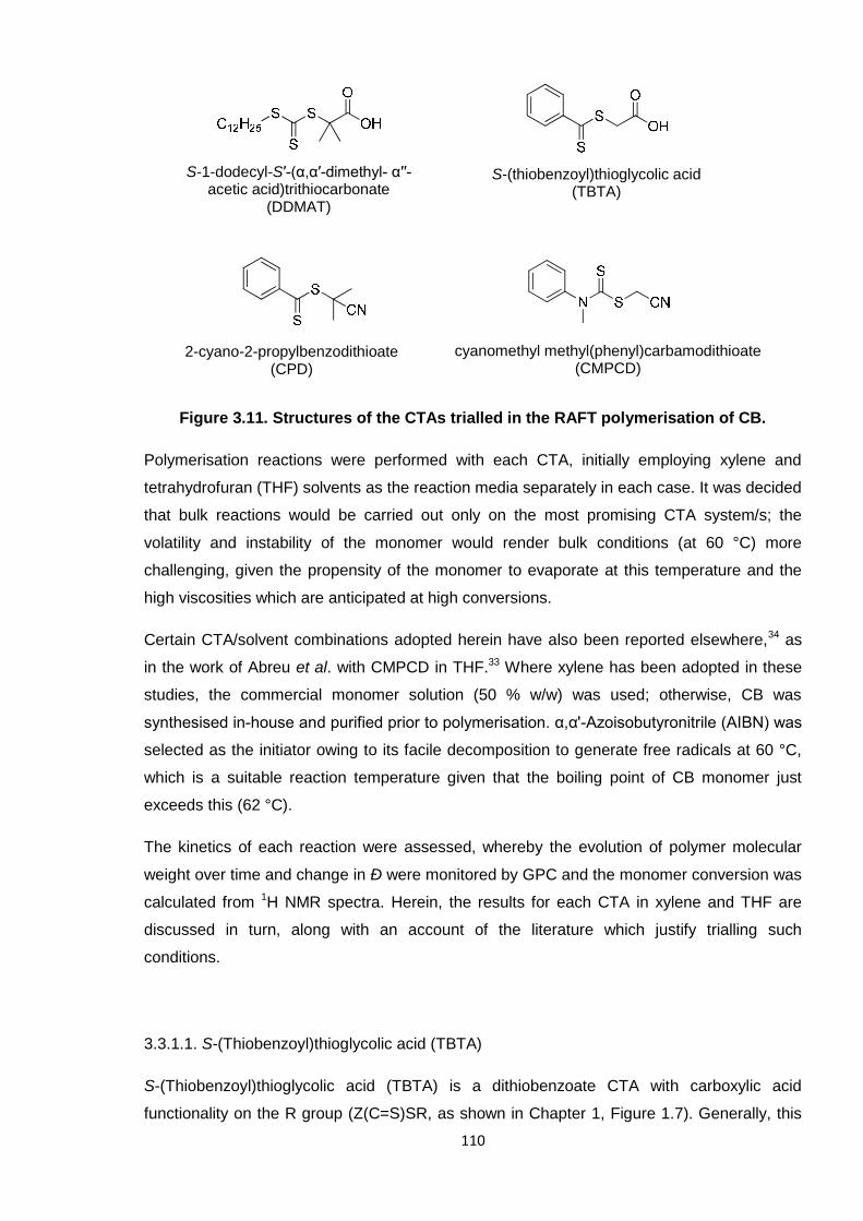
110
Figure 3.11. Structures of the CTAs trialled in the RAFT polymerisation of CB.
Polymerisation reactions were performed with each CTA, initially employing xylene and
tetrahydrofuran (THF) solvents as the reaction media separately in each case. It was decided
that bulk reactions would be carried out only on the most promising CTA system/s; the
volatility and instability of the monomer would render bulk conditions (at 60 °C) more
challenging, given the propensity of the monomer to evaporate at this temperature and the
high viscosities which are anticipated at high conversions.
Certain CTA/solvent combinations adopted herein have also been reported elsewhere,34 as
in the work of Abreu et al. with CMPCD in THF.33 Where xylene has been adopted in these
studies, the commercial monomer solution (50 % w/w) was used; otherwise, CB was
synthesised in-house and purified prior to polymerisation. α,α'-Azoisobutyronitrile (AIBN) was
selected as the initiator owing to its facile decomposition to generate free radicals at 60 °C,
which is a suitable reaction temperature given that the boiling point of CB monomer just
exceeds this (62 °C).
The kinetics of each reaction were assessed, whereby the evolution of polymer molecular
weight over time and change in Ð were monitored by GPC and the monomer conversion was
calculated from 1H NMR spectra. Herein, the results for each CTA in xylene and THF are
discussed in turn, along with an account of the literature which justify trialling such
conditions.
3.3.1.1. S-(Thiobenzoyl)thioglycolic acid (TBTA)
S-(Thiobenzoyl)thioglycolic acid (TBTA) is a dithiobenzoate CTA with carboxylic acid
functionality on the R group (Z(C=S)SR, as shown in Chapter 1, Figure 1.7). Generally, this
S-(thiobenzoyl)thioglycolic acid(TBTA)
S-1-dodecyl-S′-(α,α′-dimethyl- α′′-acetic acid)trithiocarbonate
(DDMAT)
2-cyano-2-propylbenzodithioate(CPD)
cyanomethyl methyl(phenyl)carbamodithioate(CMPCD)
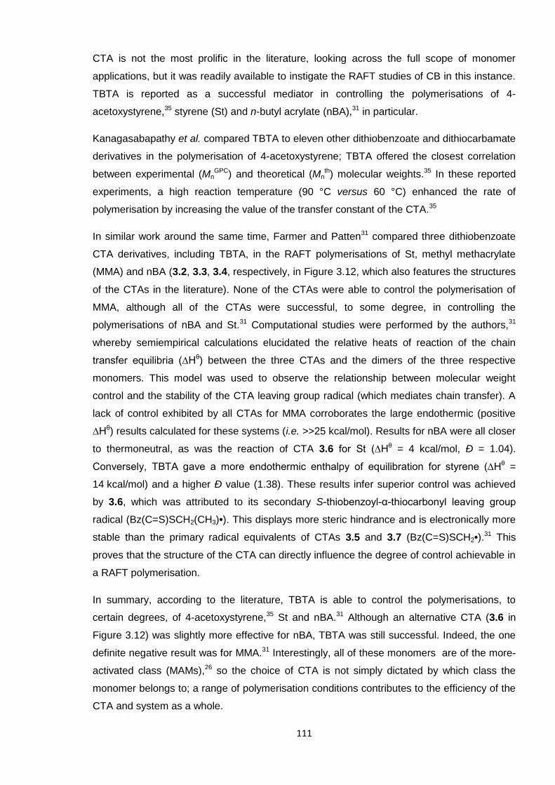
111
CTA is not the most prolific in the literature, looking across the full scope of monomer
applications, but it was readily available to instigate the RAFT studies of CB in this instance.
TBTA is reported as a successful mediator in controlling the polymerisations of 4-
acetoxystyrene,35 styrene (St) and n-butyl acrylate (nBA),31 in particular.
Kanagasabapathy et al. compared TBTA to eleven other dithiobenzoate and dithiocarbamate
derivatives in the polymerisation of 4-acetoxystyrene; TBTA offered the closest correlation
between experimental (MnGPC) and theoretical (Mn
th) molecular weights.35 In these reported
experiments, a high reaction temperature (90 °C versus 60 °C) enhanced the rate of
polymerisation by increasing the value of the transfer constant of the CTA.35
In similar work around the same time, Farmer and Patten31 compared three dithiobenzoate
CTA derivatives, including TBTA, in the RAFT polymerisations of St, methyl methacrylate
(MMA) and nBA (3.2, 3.3, 3.4, respectively, in Figure 3.12, which also features the structures
of the CTAs in the literature). None of the CTAs were able to control the polymerisation of
MMA, although all of the CTAs were successful, to some degree, in controlling the
polymerisations of nBA and St.31 Computational studies were performed by the authors,31
whereby semiempirical calculations elucidated the relative heats of reaction of the chain
transfer equilibria (∆Hθ) between the three CTAs and the dimers of the three respective
monomers. This model was used to observe the relationship between molecular weight
control and the stability of the CTA leaving group radical (which mediates chain transfer). A
lack of control exhibited by all CTAs for MMA corroborates the large endothermic (positive
∆Hθ) results calculated for these systems (i.e. >>25 kcal/mol). Results for nBA were all closer
to thermoneutral, as was the reaction of CTA 3.6 for St (∆Hθ = 4 kcal/mol, Ð = 1.04).
Conversely, TBTA gave a more endothermic enthalpy of equilibration for styrene (∆Hθ =
14 kcal/mol) and a higher Ð value (1.38). These results infer superior control was achieved
by 3.6, which was attributed to its secondary S-thiobenzoyl-α-thiocarbonyl leaving group
radical (Bz(C=S)SCH2(CH3)•). This displays more steric hindrance and is electronically more
stable than the primary radical equivalents of CTAs 3.5 and 3.7 (Bz(C=S)SCH2•).31 This
proves that the structure of the CTA can directly influence the degree of control achievable in
a RAFT polymerisation.
In summary, according to the literature, TBTA is able to control the polymerisations, to
certain degrees, of 4-acetoxystyrene,35 St and nBA.31 Although an alternative CTA (3.6 in
Figure 3.12) was slightly more effective for nBA, TBTA was still successful. Indeed, the one
definite negative result was for MMA.31 Interestingly, all of these monomers are of the more-
activated class (MAMs),26 so the choice of CTA is not simply dictated by which class the
monomer belongs to; a range of polymerisation conditions contributes to the efficiency of the
CTA and system as a whole.
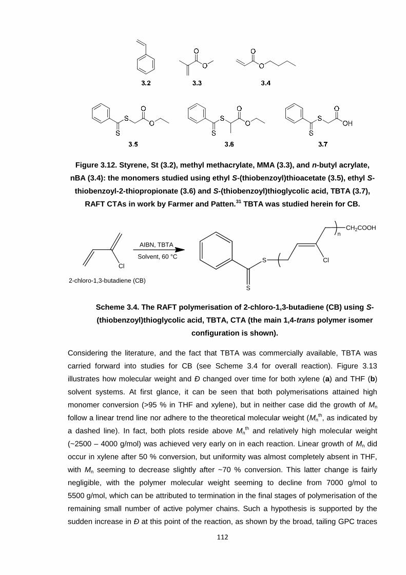
112
Figure 3.12. Styrene, St (3.2), methyl methacrylate, MMA (3.3), and n-butyl acrylate,
nBA (3.4): the monomers studied using ethyl S-(thiobenzoyl)thioacetate (3.5), ethyl S-
thiobenzoyl-2-thiopropionate (3.6) and S-(thiobenzoyl)thioglycolic acid, TBTA (3.7),
RAFT CTAs in work by Farmer and Patten.31 TBTA was studied herein for CB.
Scheme 3.4. The RAFT polymerisation of 2-chloro-1,3-butadiene (CB) using S-
(thiobenzoyl)thioglycolic acid, TBTA, CTA (the main 1,4-trans polymer isomer
configuration is shown).
Considering the literature, and the fact that TBTA was commercially available, TBTA was
carried forward into studies for CB (see Scheme 3.4 for overall reaction). Figure 3.13
illustrates how molecular weight and Ð changed over time for both xylene (a) and THF (b)
solvent systems. At first glance, it can be seen that both polymerisations attained high
monomer conversion (>95 % in THF and xylene), but in neither case did the growth of Mn
follow a linear trend line nor adhere to the theoretical molecular weight (Mnth, as indicated by
a dashed line). In fact, both plots reside above Mnth and relatively high molecular weight
(~2500 – 4000 g/mol) was achieved very early on in each reaction. Linear growth of Mn did
occur in xylene after 50 % conversion, but uniformity was almost completely absent in THF,
with Mn seeming to decrease slightly after ~70 % conversion. This latter change is fairly
negligible, with the polymer molecular weight seeming to decline from 7000 g/mol to
5500 g/mol, which can be attributed to termination in the final stages of polymerisation of the
remaining small number of active polymer chains. Such a hypothesis is supported by the
sudden increase in Ð at this point of the reaction, as shown by the broad, tailing GPC traces
Cl
Solvent, 60 °C
AIBN, TBTA
Cl
n
S
S
CH2COOH
2-chloro-1,3-butadiene (CB)
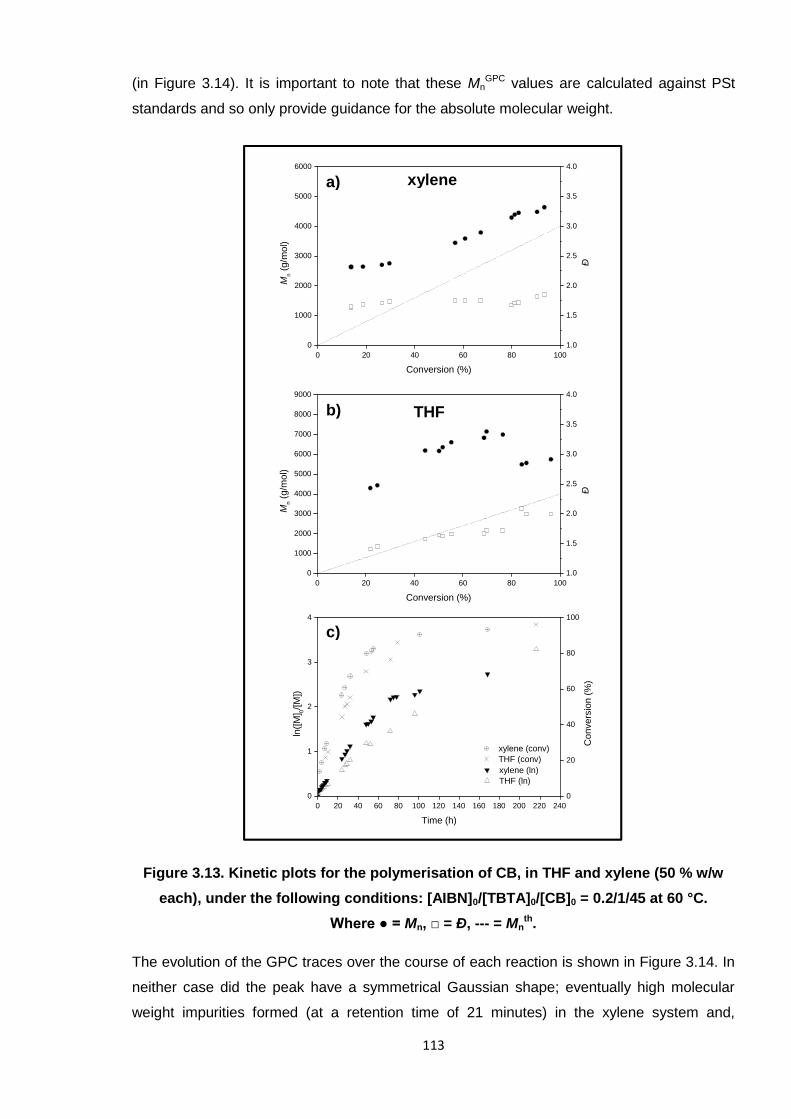
113
(in Figure 3.14). It is important to note that these MnGPC values are calculated against PSt
standards and so only provide guidance for the absolute molecular weight.
Figure 3.13. Kinetic plots for the polymerisation of CB, in THF and xylene (50 % w/w
each), under the following conditions: [AIBN]0/[TBTA]0/[CB]0 = 0.2/1/45 at 60 °C.
Where ● = Mn, □ = Ð, --- = Mnth.
The evolution of the GPC traces over the course of each reaction is shown in Figure 3.14. In
neither case did the peak have a symmetrical Gaussian shape; eventually high molecular
weight impurities formed (at a retention time of 21 minutes) in the xylene system and,
0 20 40 60 80 100 120 140 160 180 200 220 240
0
1
2
3
4
xylene (ln)THF (ln)
ln([
M] 0
/[M
])
Time (h)
0
20
40
60
80
100
xylene (conv)THF (conv)
Convers
ion
(%)
xylenea)
THFb)
c)
0 20 40 60 80 100
0
1000
2000
3000
4000
5000
6000
Mn
(g/m
ol)
Conversion (%)
1.0
1.5
2.0
2.5
3.0
3.5
4.0
Ð0 20 40 60 80 100
0
1000
2000
3000
4000
5000
6000
7000
8000
9000
Mn
(g/m
ol)
Conversion (%)
1.0
1.5
2.0
2.5
3.0
3.5
4.0
Ð
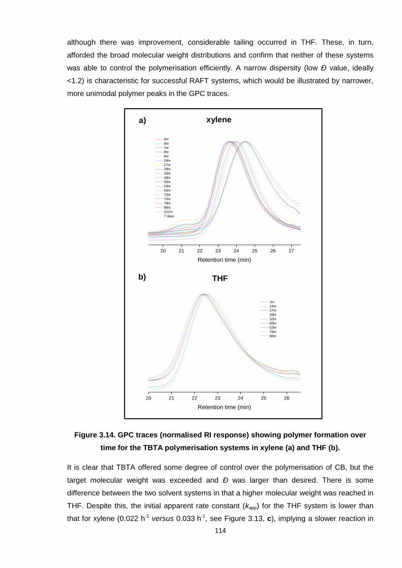
114
although there was improvement, considerable tailing occurred in THF. These, in turn,
afforded the broad molecular weight distributions and confirm that neither of these systems
was able to control the polymerisation efficiently. A narrow dispersity (low Ð value, ideally
<1.2) is characteristic for successful RAFT systems, which would be illustrated by narrower,
more unimodal polymer peaks in the GPC traces.
Figure 3.14. GPC traces (normalised RI response) showing polymer formation over
time for the TBTA polymerisation systems in xylene (a) and THF (b).
It is clear that TBTA offered some degree of control over the polymerisation of CB, but the
target molecular weight was exceeded and Ð was larger than desired. There is some
difference between the two solvent systems in that a higher molecular weight was reached in
THF. Despite this, the initial apparent rate constant (kapp) for the THF system is lower than
that for xylene (0.022 h-1 versus 0.033 h-1, see Figure 3.13, c), implying a slower reaction in
20 21 22 23 24 25 26 27
4hr5hr7hr8hr9hr24hr27hr29hr32hr48hr50hr53hr55hr72hr75hr78hr96hr101hr7 days
Retention time (min)
20 21 22 23 24 25 26
1hr24hr27hr29hr32hr48hr52hr79hr96hr
Retention time (min)
xylene
THF
a)
b)
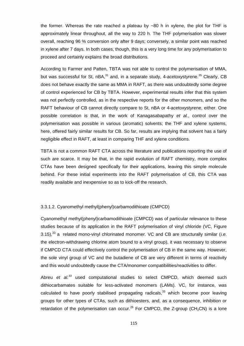
115
the former. Whereas the rate reached a plateau by ~80 h in xylene, the plot for THF is
approximately linear throughout, all the way to 220 h. The THF polymerisation was slower
overall, reaching 96 % conversion only after 9 days; conversely, a similar point was reached
in xylene after 7 days. In both cases, though, this is a very long time for any polymerisation to
proceed and certainly explains the broad distributions.
According to Farmer and Patten, TBTA was not able to control the polymerisation of MMA,
but was successful for St, nBA,31 and, in a separate study, 4-acetoxystyrene.35 Clearly, CB
does not behave exactly the same as MMA in RAFT, as there was undoubtedly some degree
of control experienced for CB by TBTA. However, experimental results infer that this system
was not perfectly controlled, as in the respective reports for the other monomers, and so the
RAFT behaviour of CB cannot directly compare to St, nBA or 4-acetoxystyrene, either. One
possible correlation is that, in the work of Kanagasabapathy et al., control over the
polymerisation was possible in various (aromatic) solvents; the THF and xylene systems,
here, offered fairly similar results for CB. So far, results are implying that solvent has a fairly
negligible effect in RAFT, at least in comparing THF and xylene conditions.
TBTA is not a common RAFT CTA across the literature and publications reporting the use of
such are scarce. It may be that, in the rapid evolution of RAFT chemistry, more complex
CTAs have been designed specifically for their applications, leaving this simple molecule
behind. For these initial experiments into the RAFT polymerisation of CB, this CTA was
readily available and inexpensive so as to kick-off the research.
3.3.1.2. Cyanomethyl methyl(phenyl)carbamodithioate (CMPCD)
Cyanomethyl methyl(phenyl)carbamodithioate (CMPCD) was of particular relevance to these
studies because of its application in the RAFT polymerisation of vinyl chloride (VC, Figure
3.15),33 a related mono-vinyl chlorinated monomer. VC and CB are structurally similar (i.e.
the electron-withdrawing chlorine atom bound to a vinyl group), it was necessary to observe
if CMPCD CTA could effectively control the polymerisation of CB in the same way. However,
the sole vinyl group of VC and the butadiene of CB are very different in terms of reactivity
and this would undoubtedly cause the CTA/monomer compatibilities/reactivities to differ.
Abreu et al.33 used computational studies to select CMPCD, which deemed such
dithiocarbamates suitable for less-activated monomers (LAMs). VC, for instance, was
calculated to have poorly stabilised propagating radicals,33 which become poor leaving
groups for other types of CTAs, such as dithioesters, and, as a consequence, inhibition or
retardation of the polymerisation can occur.26 For CMPCD, the Z-group (CH2CN) is a lone
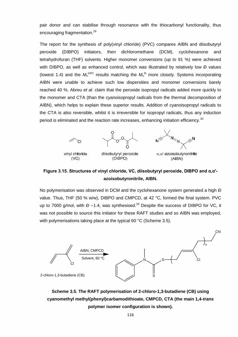
116
pair donor and can stabilise through resonance with the thiocarbonyl functionality, thus
encouraging fragmentation.26
The report for the synthesis of poly(vinyl chloride) (PVC) compares AIBN and diisobutyryl
peroxide (DIBPO) initiators, then dichloromethane (DCM), cyclohexanone and
tetrahydrofuran (THF) solvents. Higher monomer conversions (up to 91 %) were achieved
with DIBPO, as well as enhanced control, which was illustrated by relatively low Ð values
(lowest 1.4) and the MnGPC results matching the Mn
th more closely. Systems incorporating
AIBN were unable to achieve such low dispersities and monomer conversions barely
reached 40 %. Abreu et al. claim that the peroxide isopropyl radicals added more quickly to
the monomer and CTA (than the cyanoisopropyl radicals from the thermal decomposition of
AIBN), which helps to explain these superior results. Addition of cyanoisopropyl radicals to
the CTA is also reversible, whilst it is irreversible for isopropyl radicals, thus any induction
period is eliminated and the reaction rate increases, enhancing initiation efficiency.33
Figure 3.15. Structures of vinyl chloride, VC, diisobutyryl peroxide, DIBPO and α,α'-
azoisobutyronitrile, AIBN.
No polymerisation was observed in DCM and the cyclohexanone system generated a high Ð
value. Thus, THF (50 % w/w), DIBPO and CMPCD, at 42 °C, formed the final system. PVC
up to 7000 g/mol, with Ð ~1.4, was synthesised.33 Despite the success of DIBPO for VC, it
was not possible to source this initiator for these RAFT studies and so AIBN was employed,
with polymerisations taking place at the typical 60 °C (Scheme 3.5).
Scheme 3.5. The RAFT polymerisation of 2-chloro-1,3-butadiene (CB) using
cyanomethyl methyl(phenyl)carbamodithioate, CMPCD, CTA (the main 1,4-trans
polymer isomer configuration is shown).
Cl
Solvent, 60 °C
AIBN, CMPCD
Cl
n
S
S
CN
N
2-chloro-1,3-butadiene (CB)
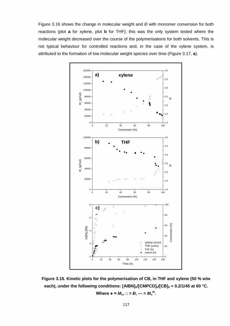
117
Figure 3.16 shows the change in molecular weight and Ð with monomer conversion for both
reactions (plot a for xylene, plot b for THF); this was the only system tested where the
molecular weight decreased over the course of the polymerisations for both solvents. This is
not typical behaviour for controlled reactions and, in the case of the xylene system, is
attributed to the formation of low molecular weight species over time (Figure 3.17, a).
Figure 3.16. Kinetic plots for the polymerisation of CB, in THF and xylene (50 % w/w
each), under the following conditions: [AIBN]0/[CMPCD]0/[CB]0 = 0.2/1/45 at 60 °C.
Where ● = Mn, □ = Ð, --- = Mnth.
xylenea)
THFb)
c)
0 20 40 60 80 100
0
20000
40000
60000
80000
100000
120000
140000
160000
Mn
(g/m
ol)
Conversion (%)
1.0
1.5
2.0
2.5
3.0
3.5
4.0
Ð
0 20 40 60 80 100
0
20000
40000
60000
80000
100000
Mn
(g/m
ol)
Conversion (%)
1.0
1.5
2.0
2.5
3.0
3.5
4.0
Ð
0 20 40 60 80 100 120 140 160
0
2
4
6
8
THF (ln)xylene (ln)
ln([
M] 0
/[M
])
TIme (h)
0
20
40
60
80
100
xylene (conv)THF (conv)
Convers
ion
(%)
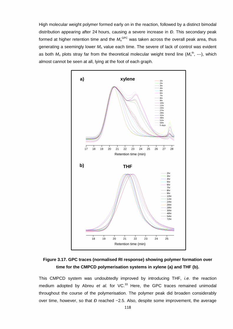
118
High molecular weight polymer formed early on in the reaction, followed by a distinct bimodal
distribution appearing after 24 hours, causing a severe increase in Ð. This secondary peak
formed at higher retention time and the MnGPC was taken across the overall peak area, thus
generating a seemingly lower Mn value each time. The severe of lack of control was evident
as both Mn plots stray far from the theoretical molecular weight trend line (Mnth, ---), which
almost cannot be seen at all, lying at the foot of each graph.
Figure 3.17. GPC traces (normalised RI response) showing polymer formation over
time for the CMPCD polymerisation systems in xylene (a) and THF (b).
This CMPCD system was undoubtedly improved by introducing THF, i.e. the reaction
medium adopted by Abreu et al. for VC.33 Here, the GPC traces remained unimodal
throughout the course of the polymerisation. The polymer peak did broaden considerably
over time, however, so that Ð reached ~2.5. Also, despite some improvement, the average
18 19 20 21 22 23 24 25
2hr3hr4hr5hr6hr7hr8hr9hr10hr11hr24hr26hr28hr30hr48hr54hr72hr
Retention time (min)
17 18 19 20 21 22 23 24 25 26 27 28
1hr2hr3hr4hr5hr6hr7hr8hr9hr10hr11hr24hr27hr29hr31hr48hr51hr54hr5 days
Retention time (min)
xylene
THF
a)
b)
119
molecular weight still decreased over time as the peak shifted and eluted at increasingly
higher retention times, yet again. Clearly, low molecular weight species were still forming, but
not to such a degree as in the xylene reaction, to generate bimodal peaks. These new
species were also closer (in retention time and molecular weight) to the majority of chains in
THF because, overall, the chains were smaller (at higher retention time) than in xylene.
Adopting the more polar, non-aromatic solvent (THF) significantly improved this
polymerisation system and offered more control, given the preferred unimodal peak shape in
the GPC traces. This solvent/CTA combination was selected according to its applicability to
VC,33 but unfortunately it was not possible to directly compare results for the different
monomers due to the use of AIBN versus DIBPO. The dispersity of the polymer increased
over time from when AIBN was employed for VC, but Ð values reached ~2.5 here for CB.
Also, the kinetic behaviour for VC was typical for a RAFT polymerisation in that molecular
weight increased linearly over time; for CB this was not the case and high molecular weight
polymers formed early on in the reactions (as is typical of conventional, uncontrolled free
radical polymerisation). The rate constants obtained in the contrasting medium for each of
these experiments differ by a factor of six; kapp in xylene being highest at 0.174 h-1, whereas
kapp = 0.034 h-1 in THF (see Figure 3.16, c, semi-logarithmic plot). These kapp values infer that
the THF reaction was slower at the start, but the gradient for this plot is steeper overall,
whereas that for xylene is more gradual. Despite this difference, they both seem to follow a
stepwise ‘S’ shaped function, (which is more pronounced in the xylene system), where an
initial steep slope is followed by a moderate plateau and then a second incline. The THF
reaction shows a final plateau as the polymerisation reached completion, from 60 hours;
xylene has a longer initial plateau at 50 – 120 hours. This ‘staggered’ behaviour was not
observed by Abreu et al. for VC using CMPCD.33
The differing reactivities of VC and CB must have contributed to the contrasting results;
CMPCD is clearly more appropriate for VC than CB. Abreu et al. define VC as a less-
activated monomer (LAM),33 which is why the dithiocarbamate is apparently suitable. The
extra double bond in the CB structure most likely renders this more-activated (a MAM),
although this is not yet official (due to the general lack of controlled polymerisation reports).
3.3.1.3. S-1-Dodecyl-S′-(α,α′-dimethyl-α′′-acetic acid)trithiocarbonate (DDMAT)
S-1-Dodecyl-S′-(α,α′-dimethyl-α′′-acetic acid)trithiocarbonate (DDMAT) was the first reported
RAFT CTA for the controlled radical polymerisation of 2-methyl-1,3-butadiene (isoprene);30
NMP has been used to synthesise predefined poly(2-methyl-1,3-butadiene) (which is more
commonly known as polyisoprene).36 The few attempts to apply ATRP to this monomer have
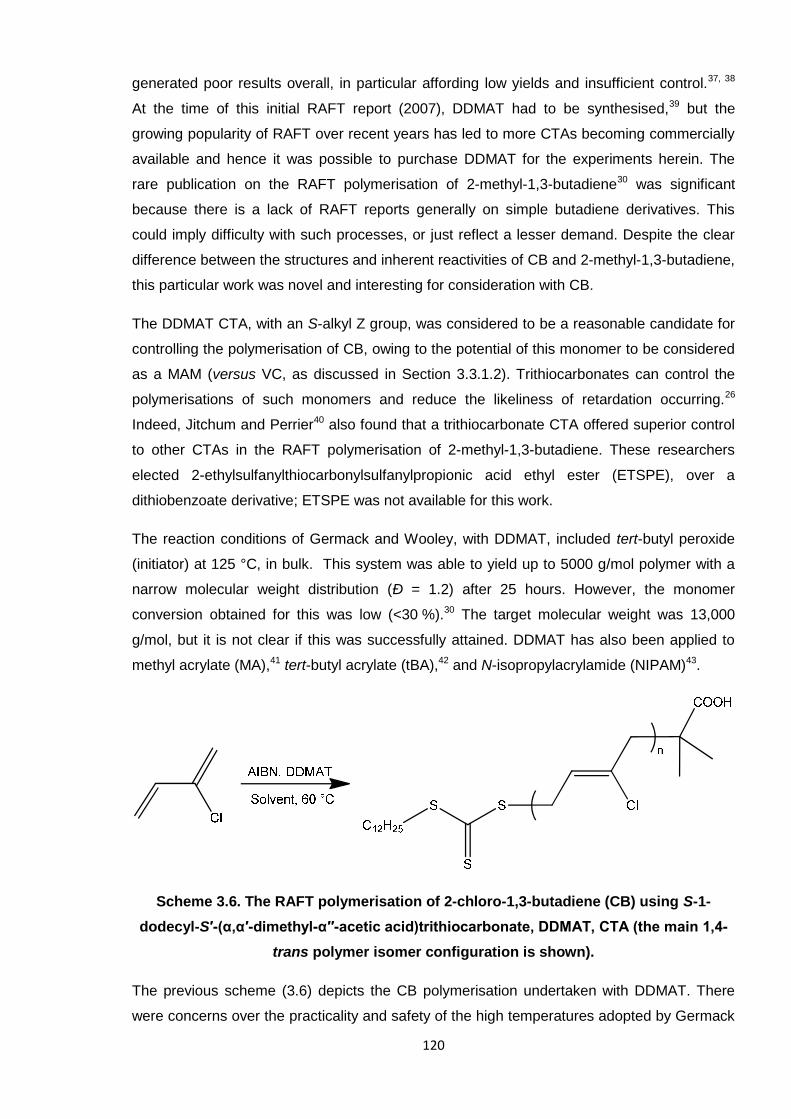
120
generated poor results overall, in particular affording low yields and insufficient control.37, 38
At the time of this initial RAFT report (2007), DDMAT had to be synthesised,39 but the
growing popularity of RAFT over recent years has led to more CTAs becoming commercially
available and hence it was possible to purchase DDMAT for the experiments herein. The
rare publication on the RAFT polymerisation of 2-methyl-1,3-butadiene30 was significant
because there is a lack of RAFT reports generally on simple butadiene derivatives. This
could imply difficulty with such processes, or just reflect a lesser demand. Despite the clear
difference between the structures and inherent reactivities of CB and 2-methyl-1,3-butadiene,
this particular work was novel and interesting for consideration with CB.
The DDMAT CTA, with an S-alkyl Z group, was considered to be a reasonable candidate for
controlling the polymerisation of CB, owing to the potential of this monomer to be considered
as a MAM (versus VC, as discussed in Section 3.3.1.2). Trithiocarbonates can control the
polymerisations of such monomers and reduce the likeliness of retardation occurring.26
Indeed, Jitchum and Perrier40 also found that a trithiocarbonate CTA offered superior control
to other CTAs in the RAFT polymerisation of 2-methyl-1,3-butadiene. These researchers
elected 2-ethylsulfanylthiocarbonylsulfanylpropionic acid ethyl ester (ETSPE), over a
dithiobenzoate derivative; ETSPE was not available for this work.
The reaction conditions of Germack and Wooley, with DDMAT, included tert-butyl peroxide
(initiator) at 125 °C, in bulk. This system was able to yield up to 5000 g/mol polymer with a
narrow molecular weight distribution (Ð = 1.2) after 25 hours. However, the monomer
conversion obtained for this was low (<30 %).30 The target molecular weight was 13,000
g/mol, but it is not clear if this was successfully attained. DDMAT has also been applied to
methyl acrylate (MA),41 tert-butyl acrylate (tBA),42 and N-isopropylacrylamide (NIPAM)43.
Scheme 3.6. The RAFT polymerisation of 2-chloro-1,3-butadiene (CB) using S-1-
dodecyl-S′-(α,α′-dimethyl-α′′-acetic acid)trithiocarbonate, DDMAT, CTA (the main 1,4-
trans polymer isomer configuration is shown).
The previous scheme (3.6) depicts the CB polymerisation undertaken with DDMAT. There
were concerns over the practicality and safety of the high temperatures adopted by Germack
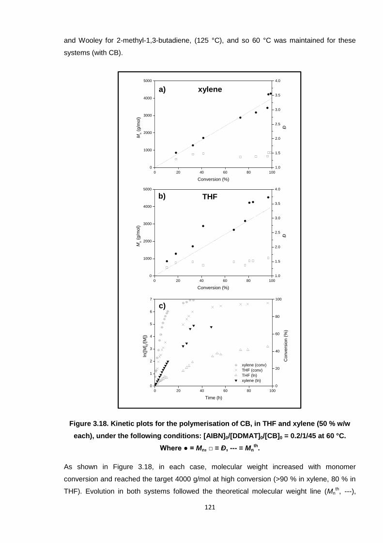
121
and Wooley for 2-methyl-1,3-butadiene, (125 °C), and so 60 °C was maintained for these
systems (with CB).
Figure 3.18. Kinetic plots for the polymerisation of CB, in THF and xylene (50 % w/w
each), under the following conditions: [AIBN]0/[DDMAT]0/[CB]0 = 0.2/1/45 at 60 °C.
Where ● = Mn, □ = Ð, --- = Mnth.
As shown in Figure 3.18, in each case, molecular weight increased with monomer
conversion and reached the target 4000 g/mol at high conversion (>90 % in xylene, 80 % in
THF). Evolution in both systems followed the theoretical molecular weight line (Mnth, ---),
xylenea)
THFb)
c)
0 20 40 60 80 100
0
1000
2000
3000
4000
5000
Mn
(g/m
ol)
Conversion (%)
1.0
1.5
2.0
2.5
3.0
3.5
4.0
Ð0 20 40 60 80 100
0
1000
2000
3000
4000
5000
Mn
(g/m
ol)
Conversion (%)
1.0
1.5
2.0
2.5
3.0
3.5
4.0
Ð
0 20 40 60 80 100
0
1
2
3
4
5
6
7
THF (ln)xylene (ln)
ln([
M] 0
/[M
])
Time (h)
0
20
40
60
80
100
xylene (conv)THF (conv)
Convers
ion
(%)
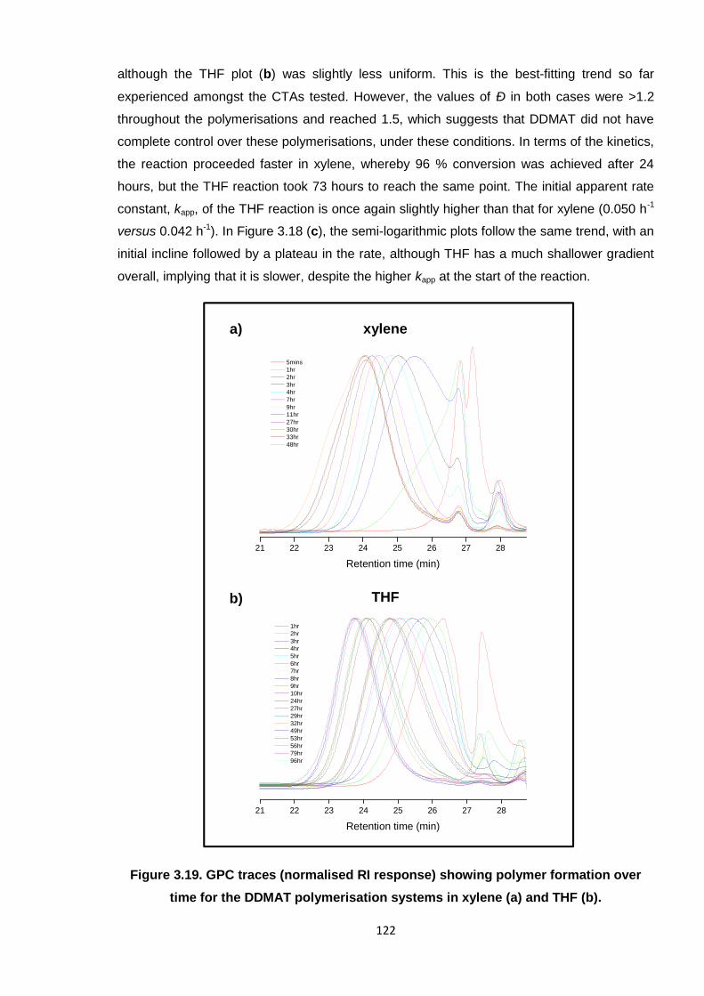
122
although the THF plot (b) was slightly less uniform. This is the best-fitting trend so far
experienced amongst the CTAs tested. However, the values of Ð in both cases were >1.2
throughout the polymerisations and reached 1.5, which suggests that DDMAT did not have
complete control over these polymerisations, under these conditions. In terms of the kinetics,
the reaction proceeded faster in xylene, whereby 96 % conversion was achieved after 24
hours, but the THF reaction took 73 hours to reach the same point. The initial apparent rate
constant, kapp, of the THF reaction is once again slightly higher than that for xylene (0.050 h-1
versus 0.042 h-1). In Figure 3.18 (c), the semi-logarithmic plots follow the same trend, with an
initial incline followed by a plateau in the rate, although THF has a much shallower gradient
overall, implying that it is slower, despite the higher kapp at the start of the reaction.
Figure 3.19. GPC traces (normalised RI response) showing polymer formation over
time for the DDMAT polymerisation systems in xylene (a) and THF (b).
21 22 23 24 25 26 27 28
1hr2hr3hr4hr5hr6hr7hr8hr9hr10hr24hr27hr29hr32hr49hr53hr56hr79hr96hr
Retention time (min)
xylene
THF
a)
b)
21 22 23 24 25 26 27 28
5mins1hr2hr3hr4hr7hr9hr11hr27hr30hr33hr48hr
Retention time (min)
123
Although the Mn and Ð results for these systems seem to be comparable, the GPC results do
demonstrate a slight difference (see Figure 3.19). For instance, the polymer peak shapes at
the start of each reaction, whilst broad for both, were more multi-modal in the case of xylene.
THF afforded unimodal polymer peaks which were generally more uniform; this arguably
demonstrates slightly more control over the growth of polymer chains.
The successful application of DDMAT to 2-methyl-1,3-butadiene30 was reasonable
justification for trials here and, accordingly, this CTA gave some promising results for the
RAFT polymerisation of CB. Molecular weight increased linearly with conversion and Mnth
was achieved in good time. However, the Ð values were still not <1.2 in either xylene or THF,
which demonstrates a loss of control over the growth of the polymer chains. GPC polymer
peak shapes were more monomodal in THF, though, which is most likely attributed to a
slightly slower polymerisation overall.
3.3.1.4. 2-Cyano-2-propylbenzodithioate (CPD)
2-Cyano-2-propylbenzodithioate (CPD) is a dithiobenzoate CTA, where Z = phenyl and
R = C(Me)2CN in the generic Z(C=S)SR structure (the structure of CPD is shown in Figure
3.11). This RAFT CTA has been successful in controlling the polymerisation of MMA44, 45 and
other (meth)acrylates,34, 46 which are defined as more-activated monomers (MAMs)26. Often
in previous reports, CPD has been selected after a rigorous screening process, where it has
performed more effectively against alternative CTAs, such as other dithiobenzoate,
dithiocarbamate and trithiocarbonate derivatives, affording narrower molecular weight
distributions in the furnished polymers.44, 45, 47 As many of these reported reactions used
AIBN as the initiator and aromatic hydrocarbon solvents (such as toluene or benzene) for the
reaction media,44-48 this gave substance to employing similar conditions in these studies.
Interestingly, CPD has also been successful in the RAFT polymerisation of 2-
(dimethylamino)ethyl methacrylate (DMAEMA) with AIBN in THF (50 % w/w).34 Thus,
studying the effects of xylene and THF in the RAFT polymerisation of CB, with CPD, is
further justified.
Interestingly, CPD was also found to be successful for Weber et al.47 to polymerise 2-
isopropenyl-2-oxazoline (iPOx) for the first time using RAFT. Here, this CTA outperformed
another trithiocarbonate and a dithiocarbamate, affording lower dispersities (Ð = 1.2 – 1.4), to
furnish low molecular weight polymer in toluene, using AIBN as the initiator.
The reason behind the success of CPD in these reported RAFT polymerisations seems to be
the effectiveness of the R group (C(Me)2CN). It is known that the R group is specifically
required to be a good leaving group and have a proficient corresponding reinitiating radical.45
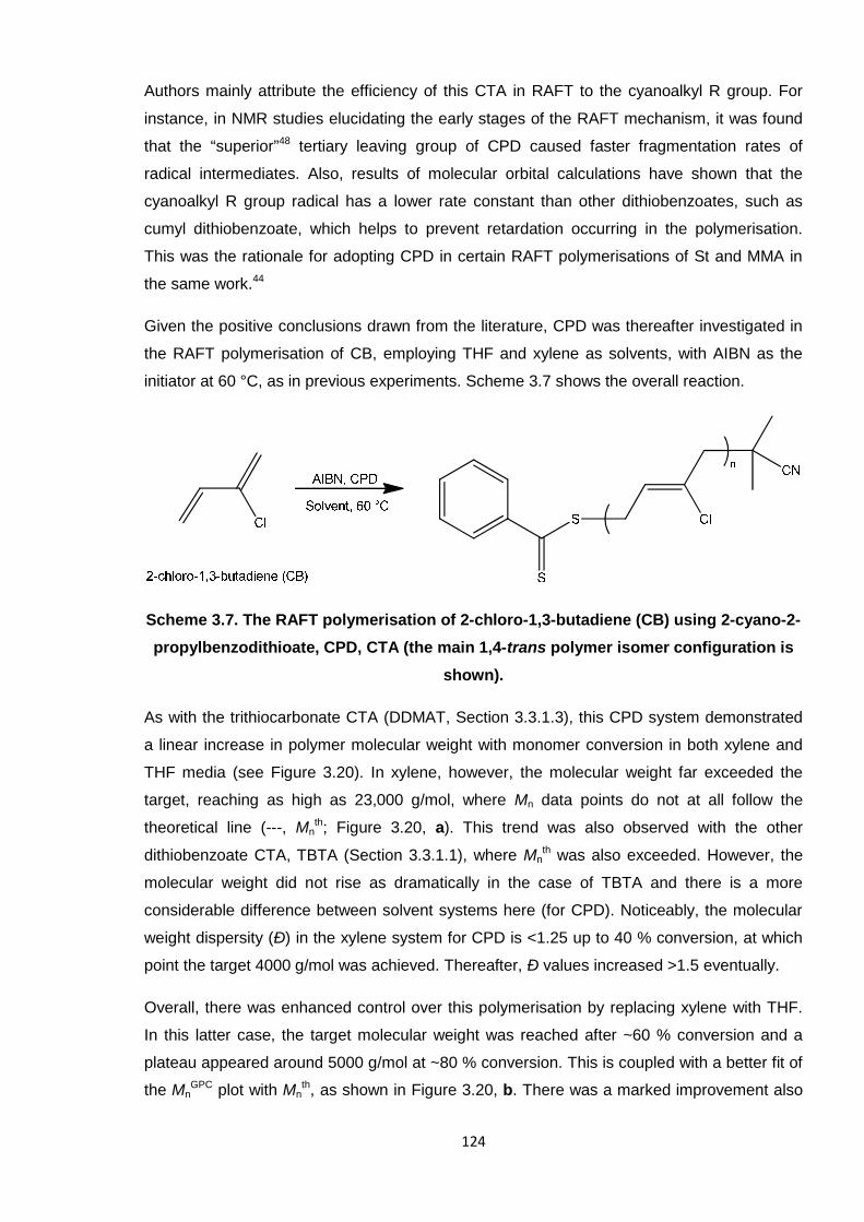
124
Authors mainly attribute the efficiency of this CTA in RAFT to the cyanoalkyl R group. For
instance, in NMR studies elucidating the early stages of the RAFT mechanism, it was found
that the “superior”48 tertiary leaving group of CPD caused faster fragmentation rates of
radical intermediates. Also, results of molecular orbital calculations have shown that the
cyanoalkyl R group radical has a lower rate constant than other dithiobenzoates, such as
cumyl dithiobenzoate, which helps to prevent retardation occurring in the polymerisation.
This was the rationale for adopting CPD in certain RAFT polymerisations of St and MMA in
the same work.44
Given the positive conclusions drawn from the literature, CPD was thereafter investigated in
the RAFT polymerisation of CB, employing THF and xylene as solvents, with AIBN as the
initiator at 60 °C, as in previous experiments. Scheme 3.7 shows the overall reaction.
Scheme 3.7. The RAFT polymerisation of 2-chloro-1,3-butadiene (CB) using 2-cyano-2-
propylbenzodithioate, CPD, CTA (the main 1,4-trans polymer isomer configuration is
shown).
As with the trithiocarbonate CTA (DDMAT, Section 3.3.1.3), this CPD system demonstrated
a linear increase in polymer molecular weight with monomer conversion in both xylene and
THF media (see Figure 3.20). In xylene, however, the molecular weight far exceeded the
target, reaching as high as 23,000 g/mol, where Mn data points do not at all follow the
theoretical line (---, Mnth; Figure 3.20, a). This trend was also observed with the other
dithiobenzoate CTA, TBTA (Section 3.3.1.1), where Mnth was also exceeded. However, the
molecular weight did not rise as dramatically in the case of TBTA and there is a more
considerable difference between solvent systems here (for CPD). Noticeably, the molecular
weight dispersity (Ð) in the xylene system for CPD is <1.25 up to 40 % conversion, at which
point the target 4000 g/mol was achieved. Thereafter, Ð values increased >1.5 eventually.
Overall, there was enhanced control over this polymerisation by replacing xylene with THF.
In this latter case, the target molecular weight was reached after ~60 % conversion and a
plateau appeared around 5000 g/mol at ~80 % conversion. This is coupled with a better fit of
the MnGPC plot with Mn
th, as shown in Figure 3.20, b. There was a marked improvement also
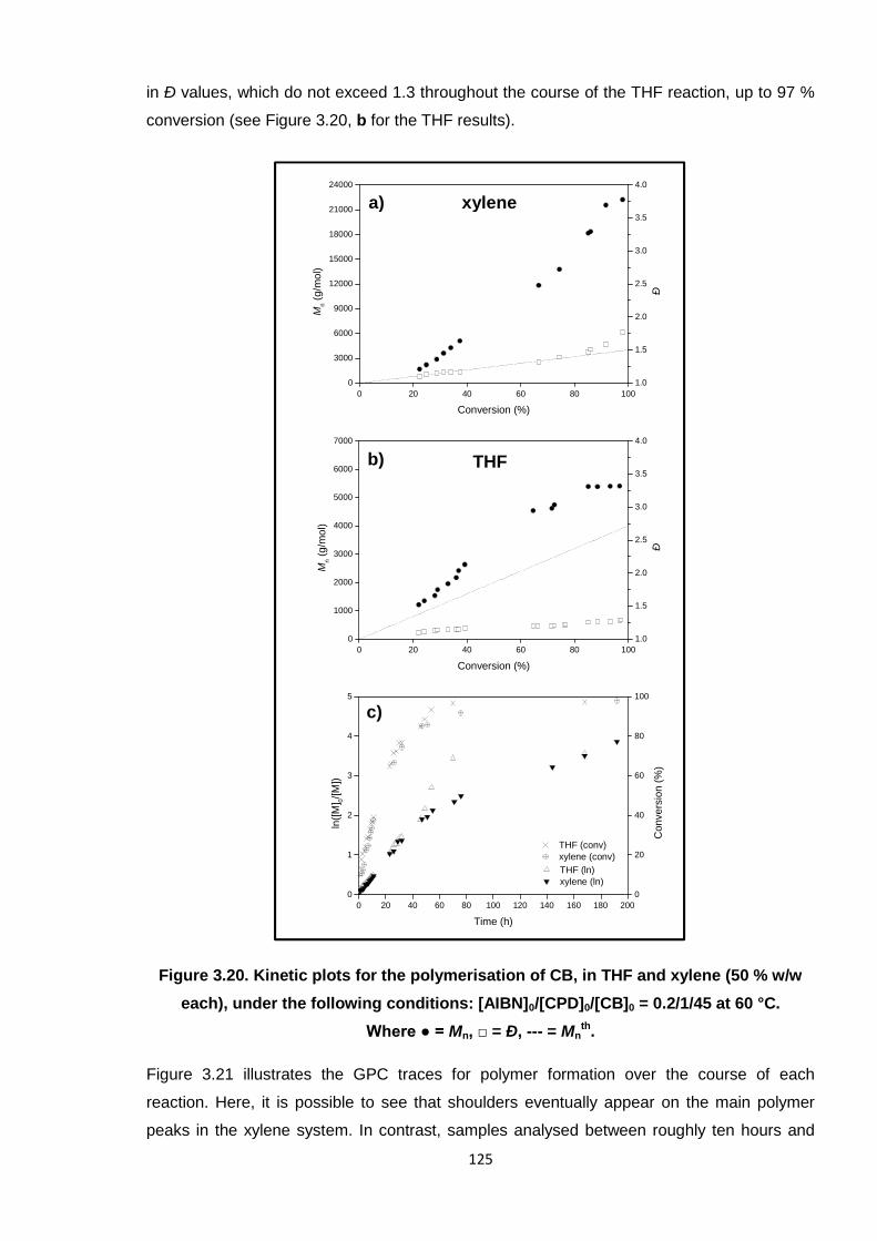
125
in Ð values, which do not exceed 1.3 throughout the course of the THF reaction, up to 97 %
conversion (see Figure 3.20, b for the THF results).
Figure 3.20. Kinetic plots for the polymerisation of CB, in THF and xylene (50 % w/w
each), under the following conditions: [AIBN]0/[CPD]0/[CB]0 = 0.2/1/45 at 60 °C.
Where ● = Mn, □ = Ð, --- = Mnth.
Figure 3.21 illustrates the GPC traces for polymer formation over the course of each
reaction. Here, it is possible to see that shoulders eventually appear on the main polymer
peaks in the xylene system. In contrast, samples analysed between roughly ten hours and
0 20 40 60 80 100
0
3000
6000
9000
12000
15000
18000
21000
24000
1.0
1.5
2.0
2.5
3.0
3.5
4.0
Mn
(g/m
ol)
Conversion (%)
Ð
xylenea)
THFb)
c)
0 20 40 60 80 100
0
1000
2000
3000
4000
5000
6000
7000
Mn
(g/m
ol)
Conversion (%)
1.0
1.5
2.0
2.5
3.0
3.5
4.0
Ð
0 20 40 60 80 100 120 140 160 180 200
0
1
2
3
4
5
THF (ln)xylene (ln)
ln([
M] 0
/[M
])
Time (h)
0
20
40
60
80
100
THF (conv)xylene (conv)
Convers
ion
(%)
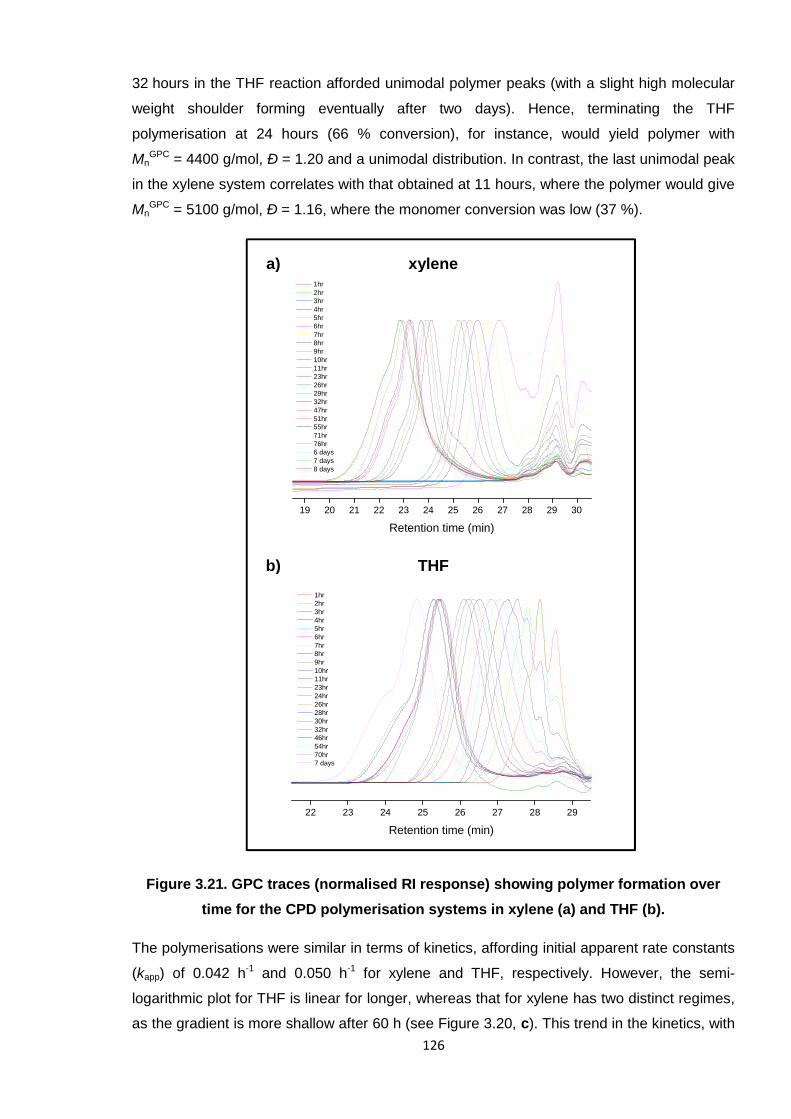
126
32 hours in the THF reaction afforded unimodal polymer peaks (with a slight high molecular
weight shoulder forming eventually after two days). Hence, terminating the THF
polymerisation at 24 hours (66 % conversion), for instance, would yield polymer with
MnGPC = 4400 g/mol, Ð = 1.20 and a unimodal distribution. In contrast, the last unimodal peak
in the xylene system correlates with that obtained at 11 hours, where the polymer would give
MnGPC = 5100 g/mol, Ð = 1.16, where the monomer conversion was low (37 %).
Figure 3.21. GPC traces (normalised RI response) showing polymer formation over
time for the CPD polymerisation systems in xylene (a) and THF (b).
The polymerisations were similar in terms of kinetics, affording initial apparent rate constants
(kapp) of 0.042 h-1 and 0.050 h-1 for xylene and THF, respectively. However, the semi-
logarithmic plot for THF is linear for longer, whereas that for xylene has two distinct regimes,
as the gradient is more shallow after 60 h (see Figure 3.20, c). This trend in the kinetics, with
22 23 24 25 26 27 28 29
1hr2hr3hr4hr5hr6hr7hr8hr9hr10hr11hr23hr24hr26hr28hr30hr32hr46hr54hr70hr7 days
Retention time (min)
19 20 21 22 23 24 25 26 27 28 29 30
1hr2hr3hr4hr5hr6hr7hr8hr9hr10hr11hr23hr26hr29hr32hr47hr51hr55hr71hr76hr6 days7 days8 days
Retention time (min)
THF
xylene
b)
a)
127
two periods in the reaction proceeding at contrasting rates, was also seen in the RAFT
polymerisation of VC in THF with CMPCD.33
It is clear that CPD is capable of controlling the polymerisation of CB in THF, with
experimental Mn values matching Mnth and narrow dispersity (Ð <1.3) throughout the
reaction. The success of CPD adds further weight to the argument that CB lies in the more-
activated category (MAM, as defined originally by Moad et al.)26 and, on the whole, behaves
similarly to (meth)acrylates,32, 34, 45, 46 to which CPD has previously been applied.
3.3.2. DDMAT and CPD RAFT polymerisation reactions in bulk
For comparative purposes, the RAFT polymerisation of CB was also conducted in bulk
conditions (i.e. not employing any additional solvent medium). The previous sets of results
for the four CTAs in solution inferred that DDMAT and CPD CTAs offered the greatest
control, in general (irrespective of solvent). Both CTAs enabled the target molecular weights
to be met at high conversions (in each solvent for DDMAT, only in THF for CPD). Also, both
CTAs performed more effectively in THF, than in xylene, as these conditions realised more
uniform, unimodal polymer peaks in the GPC. However, the distinction between the two
CTAs resides with the molecular weight distributions, whereby the values of Ð obtained for
CPD in THF remained <1.3 throughout the polymerisation, which is an excellent result.
Conversely, Ð for DDMAT reached up to 1.6.
The other CTAs, TBTA and CMPCD, were unable to control the polymerisation of CB in
solution, in that the evolution of molecular weight did not follow the Mnth trend line in any
case. Molecular weight distributions were also broad and, in the case of CMPCD, the gradual
formation of low molecular weight species caused bimodal GPC peak shapes, thus affecting
an apparent decrease in molecular weight. It was therefore decided to only investigate the
bulk RAFT polymerisations of CB with DDMAT and CPD CTAs.
In the same way as with the previous reactions in THF, the monomer was synthesised, dried
and distilled beforehand. In each case, CB was able to dissolve the reagents (AIBN and the
CTAs) in the bulk, so that the reaction media were homogeneous. The two reactions were
undertaken in parallel at 60 °C and aliquots were taken periodically to assess Mn, Ð and
conversion, as was typical throughout these RAFT investigations.
Figures 3.22 and 3.23 display the kinetics results and GPC traces, respectively, for each
system (or CTA). It should be noted that the two reactions targeted different molecular
weights (Mnth): 10,000 g/mol for CPD and 4000 g/mol for DDMAT. Considering this, the first
observation is that both systems approximately reached their Mnth: DDMAT at >95 %
128
conversion and CPD at 72 %. However, the CPD reaction continued past this point so that
the Mnth was exceeded and ~20,000 g/mol was eventually obtained by the end of the
polymerisation. This is complimented by the higher Ð values of the CPD system, in that
1.15 – 1.45 was observed up to 75 % conversion, but Ð exceeded 2.7 at >95 %. The reaction
was thus fairly controlled initially, but control was eventually lost and termination reactions
prevailed. Conversely, the Ð values decreased over time in the DDMAT system, which is
more fitting for a controlled-radical polymerisation.49, 50 The value of Ð decreased from 1.4 to
1.25 from 50 to 95 % conversion. Although both reactions reached high conversion (>90 %),
this was achieved more readily for DDMAT after just eight hours; at a similar point in the
CPD reaction, only 75 % monomer was consumed. Hence, the faster polymerisation was
that employing DDMAT, which yielded a higher initial apparent rate constant, kapp, of
1.248 h-1, whereas that for CPD was 0.247 h-1.
The results of the periodic GPC analyses are displayed subsequently in Figure 3.23 for
DDMAT and CPD, respectively. Here, the evolution of the polymer peaks over time
compliments the dispersity results for each system. For instance, the gradual decrease of the
Ð values for the DDMAT system is demonstrated by narrowing of the peak (graph a); initially
the peak is quite broad, but this is rectified as the RAFT equilibrium becomes established
and all the radicals become incorporated into propagation reactions. In contrast, the GPC
peak shape broadens over time for CPD (graph b) and a high molecular weight shoulder
begins to appear after just four hours. This progresses until the molecular weight distribution
is very broad at the end of polymerisation (Ð >2.7 at >95 %).
In comparing the results of each of the bulk reactions with those previously in solution, it was
concluded that swapping xylene solvent for THF vastly improved the DDMAT system overall
(see Section 3.3.1.3). This conclusion was reached because of the more unimodal GPC
peaks obtained in THF; the xylene system saw multi-modal peaks initially. For the equivalent
bulk reaction, the GPC also shows unimodal peaks, although the dispersity is shown to
decrease over time for this system. A reduction from 1.4 to 1.25 is a vast improvement on the
solution systems for this CTA, where the value of Ð increased up to 1.6 in THF. Hence, the
bulk system is favoured over solution for DDMAT, overall, even outshining the respectable
results obtained in THF.
The CPD system in THF was especially promising as this yielded monodisperse polymer of
the target molecular weight at high conversion. Crucially, Ð remained <1.3 over the course of
the polymerisation. This was an improvement on the xylene system, where higher Ð values
were obtained (reaching 1.8) and the Mnth was far exceeded. The corresponding bulk
reaction saw intermediary results, which were lower than those in xylene, but still higher than
those in THF; the increase in Ð from 1.15 to 1.45 up to 75 % conversion in bulk is inferior to
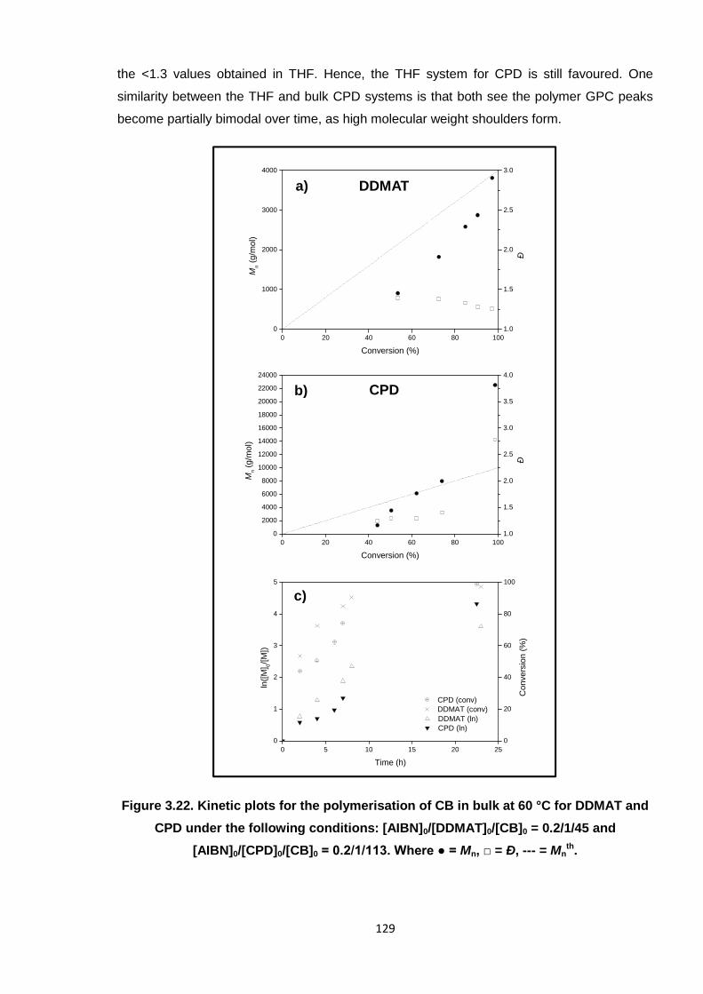
129
the <1.3 values obtained in THF. Hence, the THF system for CPD is still favoured. One
similarity between the THF and bulk CPD systems is that both see the polymer GPC peaks
become partially bimodal over time, as high molecular weight shoulders form.
Figure 3.22. Kinetic plots for the polymerisation of CB in bulk at 60 °C for DDMAT and
CPD under the following conditions: [AIBN]0/[DDMAT]0/[CB]0 = 0.2/1/45 and
[AIBN]0/[CPD]0/[CB]0 = 0.2/1/113. Where ● = Mn, □ = Ð, --- = Mnth.
DDMATa)
CPDb)
c)
0 20 40 60 80 100
0
1000
2000
3000
4000
Mn
(g/m
ol)
Conversion (%)
1.0
1.5
2.0
2.5
3.0
Ð
0 20 40 60 80 100
0
2000
4000
6000
8000
10000
12000
14000
16000
18000
20000
22000
24000
Mn
(g/m
ol)
Conversion (%)
1.0
1.5
2.0
2.5
3.0
3.5
4.0
Ð
0 5 10 15 20 25
0
1
2
3
4
5
DDMAT (ln)CPD (ln)
ln([
M] 0
/[M
])
Time (h)
0
20
40
60
80
100
CPD (conv)DDMAT (conv)
Convers
ion
(%)
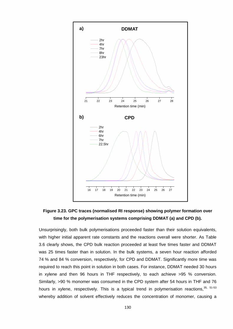
130
Figure 3.23. GPC traces (normalised RI response) showing polymer formation over
time for the polymerisation systems comprising DDMAT (a) and CPD (b).
Unsurprisingly, both bulk polymerisations proceeded faster than their solution equivalents,
with higher initial apparent rate constants and the reactions overall were shorter. As Table
3.6 clearly shows, the CPD bulk reaction proceeded at least five times faster and DDMAT
was 25 times faster than in solution. In the bulk systems, a seven hour reaction afforded
74 % and 84 % conversion, respectively, for CPD and DDMAT. Significantly more time was
required to reach this point in solution in both cases. For instance, DDMAT needed 30 hours
in xylene and then 96 hours in THF respectively, to each achieve >95 % conversion.
Similarly, >90 % monomer was consumed in the CPD system after 54 hours in THF and 76
hours in xylene, respectively. This is a typical trend in polymerisation reactions,35, 51-53
whereby addition of solvent effectively reduces the concentration of monomer, causing a
21 22 23 24 25 26 27 28
Retention time (min)
2hr4hr7hr8hr23hr
DDMAT
CPD
a)
b)
16 17 18 19 20 21 22 23 24 25 26 27
Retention time (min)
2hr4hr6hr7hr22.5hr
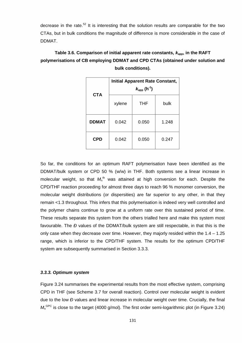
131
decrease in the rate.52 It is interesting that the solution results are comparable for the two
CTAs, but in bulk conditions the magnitude of difference is more considerable in the case of
DDMAT.
Table 3.6. Comparison of initial apparent rate constants, kapp, in the RAFT
polymerisations of CB employing DDMAT and CPD CTAs (obtained under solution and
bulk conditions).
CTA
Initial Apparent Rate Constant,
kapp (h-1)
xylene THF bulk
DDMAT 0.042 0.050 1.248
CPD 0.042 0.050 0.247
So far, the conditions for an optimum RAFT polymerisation have been identified as the
DDMAT/bulk system or CPD 50 % (w/w) in THF. Both systems see a linear increase in
molecular weight, so that Mnth was attained at high conversion for each. Despite the
CPD/THF reaction proceeding for almost three days to reach 96 % monomer conversion, the
molecular weight distributions (or dispersities) are far superior to any other, in that they
remain <1.3 throughout. This infers that this polymerisation is indeed very well controlled and
the polymer chains continue to grow at a uniform rate over this sustained period of time.
These results separate this system from the others trialled here and make this system most
favourable. The Ð values of the DDMAT/bulk system are still respectable, in that this is the
only case when they decrease over time. However, they majorly resided within the 1.4 – 1.25
range, which is inferior to the CPD/THF system. The results for the optimum CPD/THF
system are subsequently summarised in Section 3.3.3.
3.3.3. Optimum system
Figure 3.24 summarises the experimental results from the most effective system, comprising
CPD in THF (see Scheme 3.7 for overall reaction). Control over molecular weight is evident
due to the low Ð values and linear increase in molecular weight over time. Crucially, the final
MnGPC is close to the target (4000 g/mol). The first order semi-logarithmic plot (in Figure 3.24)
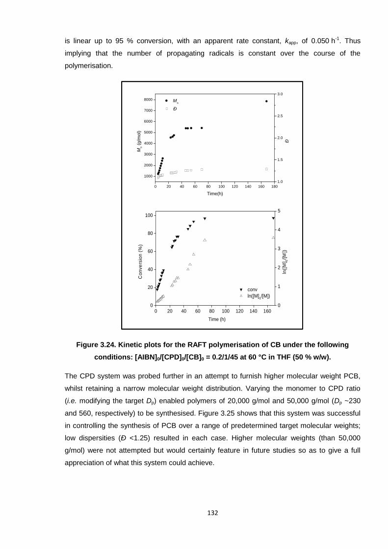
132
is linear up to 95 % conversion, with an apparent rate constant, kapp, of 0.050 h-1. Thus
implying that the number of propagating radicals is constant over the course of the
polymerisation.
Figure 3.24. Kinetic plots for the RAFT polymerisation of CB under the following
conditions: [AIBN]0/[CPD]0/[CB]0 = 0.2/1/45 at 60 °C in THF (50 % w/w).
The CPD system was probed further in an attempt to furnish higher molecular weight PCB,
whilst retaining a narrow molecular weight distribution. Varying the monomer to CPD ratio
(i.e. modifying the target Dp) enabled polymers of 20,000 g/mol and 50,000 g/mol (Dp ~230
and 560, respectively) to be synthesised. Figure 3.25 shows that this system was successful
in controlling the synthesis of PCB over a range of predetermined target molecular weights;
low dispersities (Ð <1.25) resulted in each case. Higher molecular weights (than 50,000
g/mol) were not attempted but would certainly feature in future studies so as to give a full
appreciation of what this system could achieve.
0 20 40 60 80 100 120 140 1600
20
40
60
80
100
conv
Co
nve
rsio
n(%
)
Time (h)
0
1
2
3
4
5
ln([M]0/[M])
ln([
M] 0
/[M
])
0 20 40 60 80 100 120 140 160 180
1000
2000
3000
4000
5000
6000
7000
8000 Mn
Mn
(g/m
ol)
Time(h)
1.0
1.5
2.0
2.5
3.0
Ð
Ð
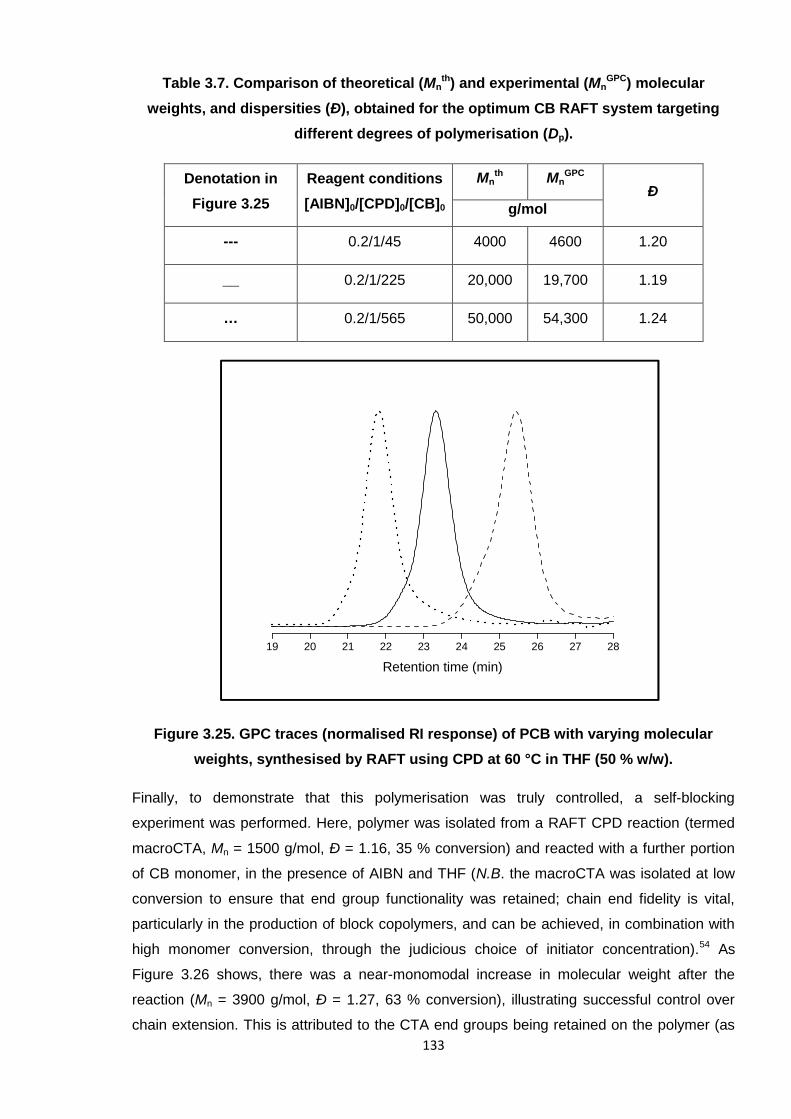
133
Table 3.7. Comparison of theoretical (Mnth) and experimental (Mn
GPC) molecular
weights, and dispersities (Ð), obtained for the optimum CB RAFT system targeting
different degrees of polymerisation (Dp).
Denotation in
Figure 3.25
Reagent conditions
[AIBN]0/[CPD]0/[CB]0
Mnth Mn
GPC
Ðg/mol
--- 0.2/1/45 4000 4600 1.20
__ 0.2/1/225 20,000 19,700 1.19
… 0.2/1/565 50,000 54,300 1.24
Figure 3.25. GPC traces (normalised RI response) of PCB with varying molecular
weights, synthesised by RAFT using CPD at 60 °C in THF (50 % w/w).
Finally, to demonstrate that this polymerisation was truly controlled, a self-blocking
experiment was performed. Here, polymer was isolated from a RAFT CPD reaction (termed
macroCTA, Mn = 1500 g/mol, Ð = 1.16, 35 % conversion) and reacted with a further portion
of CB monomer, in the presence of AIBN and THF (N.B. the macroCTA was isolated at low
conversion to ensure that end group functionality was retained; chain end fidelity is vital,
particularly in the production of block copolymers, and can be achieved, in combination with
high monomer conversion, through the judicious choice of initiator concentration).54 As
Figure 3.26 shows, there was a near-monomodal increase in molecular weight after the
reaction (Mn = 3900 g/mol, Ð = 1.27, 63 % conversion), illustrating successful control over
chain extension. This is attributed to the CTA end groups being retained on the polymer (as
19 20 21 22 23 24 25 26 27 28
Retention time (min)
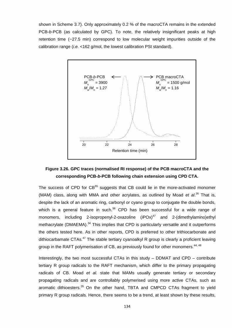
134
shown in Scheme 3.7). Only approximately 0.2 % of the macroCTA remains in the extended
PCB-b-PCB (as calculated by GPC). To note, the relatively insignificant peaks at high
retention time (~27.5 min) correspond to low molecular weight impurities outside of the
calibration range (i.e. <162 g/mol, the lowest calibration PSt standard).
Figure 3.26. GPC traces (normalised RI response) of the PCB macroCTA and the
corresponding PCB-b-PCB following chain extension using CPD CTA.
The success of CPD for CB55 suggests that CB could lie in the more-activated monomer
(MAM) class, along with MMA and other acrylates, as outlined by Moad et al.26 That is,
despite the lack of an aromatic ring, carbonyl or cyano group to conjugate the double bonds,
which is a general feature in such.56 CPD has been successful for a wide range of
monomers, including 2-isopropenyl-2-oxazoline (iPOx)47 and 2-(dimethylamino)ethyl
methacrylate (DMAEMA).34 This implies that CPD is particularly versatile and it outperforms
the others tested here. As in other reports, CPD is preferred to other trithiocarbonate and
dithiocarbamate CTAs.47 The stable tertiary cyanoalkyl R group is clearly a proficient leaving
group in the RAFT polymerisation of CB, as previously found for other monomers.44, 48
Interestingly, the two most successful CTAs in this study – DDMAT and CPD – contribute
tertiary R group radicals to the RAFT mechanism, which differ to the primary propagating
radicals of CB. Moad et al. state that MAMs usually generate tertiary or secondary
propagating radicals and are controllably polymerised using more active CTAs, such as
aromatic dithioesters.26 On the other hand, TBTA and CMPCD CTAs fragment to yield
primary R group radicals. Hence, there seems to be a trend, at least shown by these results,
20 22 24 26 28
Retention time (min)
PCB-b-PCB
Mn
GPC= 3900
Mw/M
n= 1.27
PCB macroCTA
Mn
GPC= 1500 g/mol
Mw/M
n= 1.16
135
that the CTA and monomer must contribute contrasting types of radicals to the mechanism,
for successful control. This would help to rationalise the success of CPD for CB.
Throughout the course of this study, it was observed that THF (as the solvent medium)
offered more control over the polymerisations than xylene. There was generally better
correlation between the experimental and theoretical molecular weights, and lower dispersity
(Ð) values, for all CTAs except TBTA; overall, there was negligible difference between the
solvent systems for TBTA. Despite the uncharacteristic decrease in average molecular
weights over time for CMPCD, THF also still improved this system.
The reason for these differences caused by only a change in solvent is not obvious. In
general, there is a shortage of literature reporting on, and justifying, the effects of solvent but
a small number of studies have been undertaken.45, 52, 53, 57 Overall, the polarity/aromaticity of
the solvent has been deduced irrelevant,53 as with other properties such as viscosity.57
Instead, the ability of the solvent to dissolve the initiator57 or CTA45 has been deemed
influential. In the latter case, Benaglia et al.45 found that acetonitrile (ACN) and DMF were
more capable of dissolving a pyridinium toluenesulfonate salt derivative of CPD (than
benzene), which allowed higher conversions to be achieved. However, the authors do admit
that solvent effects were relatively minor.45 Solvent has been seen to affect the initiation
stage of the free radical RAFT mechanism, though, in particular how readily the initiator
decomposes.57 For instance, in N,N'-dimethylacetamide (DMAc), 2,2′-azobis(N-butyl-2-
methylpropionamide) decomposed faster than in toluene. This correlated with achieving
higher monomer conversions in the former system; all solvents tested were able to
comparably control the molecular weight.57
Considering the conclusions regarding solvent effects in literature, THF prevailing over
xylene in these studies may be due to a number of factors, including the solubilities of AIBN,
the CTAs or the monomer itself. Perhaps, these results correlate with those of Durr et al., in
that the decomposition of AIBN is more efficient in THF. On the whole, however, reactions
proceeded slightly slower in this solvent, which fortunately did not cause broader molecular
weight distributions. Also, as for the work reported by Benaglia et al.,45 the CTAs may be
more soluble in THF and, thus, contribute to a more efficient addition-fragmentation
mechanism. It may also just be a simple case of CB having a greater affinity for THF than
xylene. The additional study into bulk polymerisation (Section 3.3.2) also enabled the
conclusion that the 50 % (w/w) THF system was the favoured condition for CB, as this
offered much lower Ð values. This further substantiates the claim that solubility is key; THF is
more capable of dissolving all of the reagents and allowing for controlled polymerisation,
whereas CB as the sole solvent does not offer such control. Without further studies of this
nature it is difficult to draw definitive conclusions as to the effect of solvent, on the whole.
136
3.4. Conclusion and future work
2-Chloro-1,3-butadiene (CB) monomer has been effectively synthesised through the
dehydrochlorination of 3,4-dichloro-1-butene. A phase-transfer catalyst (PTC) was able to
minimise the temperature and duration of the reaction and a minimum base concentration of
25 % (w/v) was proven necessary.8 CB was stabilised by phenothiazine (0.1 % w/w), which
enabled dependable storage for up to two weeks.
If more importance was placed on the monomer synthesis stage, attempts would have been
made to further optimise the conditions for this reaction. For instance, higher concentrations
of sodium hydroxide (than the typical 25 % w/v)8 would be trialled to see the effects on
product yield and reaction time. Given the overall capricious nature of the synthesis, the
laboratory-scale process would certainly need to be fine-tuned so as to provide a more
reliable procedure for future research.
PCB was initially synthesised using 1-dodecanethiol CTA and AIBN at 55 °C.15 These
conditions yielded polymers with molecular weights between 2000 – 3000 g/mol and broad
dispersities (Ð = 1.5 – 2.0). These studies were a precursor to the investigations into RAFT
for CB; more specialised conditions were deemed necessary for accurately managing
polymer growth, to ultimately predefine the polymer over a wide range of molecular weights.
Controlled polymerisation of CB by RAFT has been successfully demonstrated for the first
time employing 2-cyano-2-propylbenzodithioate (CPD) CTA, THF (50 % w/w) and AIBN at
60 °C, to yield homopolymers up to 50,000 g/mol with narrow molecular weight distributions
(Ð <1.25).55 A successful self-blocking experiment has also verified that the CTA end group
was retained and able to react further. The current capabilities of this CPD/THF system have
not quite been fully assessed, though, as it is not known how high a molecular weight is truly
achievable. Therefore, future work would include altering the monomer:CTA ratio to target
even higher molecular weights (i.e. >50,000 g/mol) to evaluate the upper limit of this system.
The success of CPD in providing more control than the other CTAs tested [S-
(thiobenzoyl)thioglycolic acid, TBTA, cyanomethyl methyl(phenyl)carbamodithioate, CMPCD,
and S-1-dodecyl-S′-(α,α′-dimethyl-α′′-acetic acid)trithiocarbonate, DDMAT] is largely
attributed to a “superior”48 leaving group (R = C(Me)2CN). Overall, CPD has shown great
versatility as a CTA for other monomers such as methyl methacrylate (MMA)44, 45 and other
acrylates,34, 46 which are all classified as more-activated monomers (MAMs).26 The DDMAT
CTA, a trithiocarbonate derivative, also performed relatively well for CB (see Section 3.3.1.3),
affording polymer with molecular weights close to Mnth at high conversion. This CTA, being a
trithiocarbonate, is also known to effectively control the polymerisations of MAMs.26 Hence, it
is not a coincidence that these two CTAs are the most suitable (of those tested) for CB; for
137
the first time, it is possible to classify CB as a MAM, within the realm of RAFT chemistry. The
less successful experimental results also support this theory, in that CMPCD (Section
3.3.1.2), a successful CTA for the RAFT polymerisation of vinyl chloride (VC), a less-
activated monomer (LAM),33 did not control the polymerisation in this instance.
It is possible that an alternative initiator, and/or concentration thereof, may be more suitable
in the RAFT polymerisation of CB, although the boiling point of this monomer (62 °C) limits
the reaction temperature. Ideally, a lower temperature system with the same, if not improved,
capabilities would be sought for a more viable application in industry, perhaps to enable the
synthesis of predefined PCB on a larger scale. It is also apparent that solvent has a vital role
in RAFT; throughout these experiments, the THF systems have shown enhanced control
(versus xylene), but these were also slower reactions. Bulk polymerisations (undertaken with
DDMAT and CPD) proceeded more rapidly, but resulted in higher dispersities. It is thought
that the solubility of the CTA45 or initiator57 caused the contrasting results obtained with the
solvent systems investigated herein. Further research into RAFT of CB is necessary,
whereby a broader range of solvents should be tested at varying concentrations. There are
numerous reports of systems employing aromatic solvents, especially combined with the
same CTAs trialled in this work,31, 45, 47 and THF features fairly widely.33, 34 Thus, it would be
interesting to examine the effects of completely different types of solvent, such as DMF or
ACN, which were investigated by Benaglia et al. in the controlled polymerisations of MMA.45
It may be feasible for the optimum CPD system discovered here to be further improved with
a lower concentration of solvent, especially given that reasonable results were obtained for
DDMAT and CPD under bulk conditions. Hence, a concentration (at least of THF) residing
between zero and 50 % (w/w) may afford monodisperse, predefined polymer in an optimum
reaction time.
3.5. References
1. G. Odian, Principles of Polymerization, Wiley Interscience, New York, 1991.2. C. M. Blow and C. Hepburn, eds., Rubber Technology and Manufacture, Butterworths,
London, 1982.3. W. Hofmann, Rubber Technology Handbook, Hanser, Munich, 1996.4. M. Lynch, Chem.-Biol. Interact., 2001, 135-136, 155-167.5. I. E. Muskat and H. E. Northrup, J. Am. Chem. Soc., 1930, 52, 4043-4055.6. US Pat., 4540838, 1985.7. US Pat., 4125564, 1978.8. EP Pat., 0001905, 1978.9. EP Pat., 0114643, 1984.10. M. Orchin, F. Kaplan, R. S. Macomber, R. M. Wilson and H. Zimmer, The Vocabulary of
Organic Chemistry, Wiley, New York, 1980.11. L. M. Mascavage, F. Zhang-Plasket, P. E. Sonnet and D. R. Dalton, Tetrahedron, 2008, 64,
9357-9367.12. W. H. Carothers, I. Williams, A. M. Collins and J. E. Kirby, J. Am. Chem. Soc., 1931, 53, 4203-
4225.
138
13. N. Makhiyanov and A. S. Khachaturov, Polymer Science, Ser. A, 2010, 52, 209 - 219.14. US Pat., 2978501, 1961.15. US Pat., 5523355, 1996.16. K. Itoyama, N. Hirashima, J. Hirano and T. Kadowaki, Polym. J., 1991, 23, 859-864.17. K. Itoyama, N. Shimizu and S. Matsuzawa, Polym. J., 1991, 23, 1139-1142.18. P. J. Flory, Principles of Polymer Chemistry, Cornell University Press, New York, 1953.19. J. M. G. Cowie, Polymers: Chemistry & Physics of Modern Materials, Chapham & Hall, Bath,
1991.20. R. C. Ferguson, J. Polym. Sci., Part A: Gen. Pap., 1964, 2, 4735-4741.21. C. W. Evans, Practical Rubber Compounding and Processing, Applied Science Publishers,
London, 1981.22. G. Odian, in Elastomers and Rubber Elasticity, ACS Symposium Series, 1982, vol. 193, ch. 1,
pp. 1-31.23. T. Yoshida, Mater. Trans., 2003, 44, 2489-2493.24. K. O. Calvert, in Polymer Latices and their Applications, ed. K. O. Calvert, Applied Science
Publishers, London, 1982, pp. 1-10.25. N. Ajellal, C. M. Thomas and J.-F. Carpentier, Polymer, 2008, 49, 4344-4349.26. G. Moad, E. Rizzardo and S. H. Thang, Acc. Chem. Res., 2008, 41, 1133-1142.27. G. Moad, E. Rizzardo and S. H. Thang, Aust. J. Chem., 2005, 58, 379-410.28. G. Moad, E. Rizzardo and S. H. Thang, Aust. J. Chem., 2009, 62, 1402-1472.29. R. P. Babu and R. Dhamodharan, Polym. Int., 2008, 57, 365-371.30. D. S. Germack and K. L. Wooley, J. Polym. Sci., Part A: Polym. Chem., 2007, 45, 4100-4108.31. S. C. Farmer and T. E. Patten, J. Polym. Sci., Part A: Polym. Chem., 2002, 40, 555-563.32. Y. K. Chong, J. Krstina, T. P. T. Le, G. Moad, A. Postma, E. Rizzardo and S. H. Thang,
Macromolecules, 2003, 36, 2256-2272.33. C. M. R. Abreu, P. V. Mendonça, A. C. Serra, J. F. J. Coelho, A. V. Popov, G. Gryn’ova, M. L.
Coote and T. Guliashvili, Macromolecules, 2012, 45, 2200-2208.34. W. Cai, W. Wan, C. Hong, C. Huang and C. Pan, Soft Matter, 2010, 6, 5554-5561.35. S. Kanagasabapathy, A. Sudalai and B. C. Benicewicz, Macromol. Rapid Commun., 2001, 22,
1076-1080.36. D. Benoit, E. Harth, P. Fox, R. M. Waymouth and C. J. Hawker, Macromolecules, 2000, 33,
363-370.37. J. Li, J. El harfi, S. M. Howdle, K. Carmichael and D. J. Irvine, Polym. Chem., 2012, 3, 1495-
1501.38. J. Wootthikanokkhan, M. Peesan and P. Phinyocheep, Eur. Polym. J., 2001, 37, 2063-2071.39. J. T. Lai, D. Filla and R. Shea, Macromolecules, 2002, 35, 6754-6756.40. V. Jitchum and S. Perrier, Macromolecules, 2007, 40, 1408-1412.41. L. Lu, N. Yang and Y. Cai, Chem. Commun., 2005, 5287-5288.42. A. M. Nyström and K. L. Wooley, Tetrahedron, 2008, 64, 8543-8552.43. B. Ebeling and P. Vana, Macromolecules, 2013, 46, 4862-4871.44. Y. K. Chong, J. Krstina, T. P. T. Le, G. Moad, A. Postma, E. Rizzardo and S. H. Thang,
Macromolecules, 2003, 36, 2256-2272.45. M. Benaglia, E. Rizzardo, A. Alberti and M. Guerra, Macromolecules, 2005, 38, 3129-3140.46. E. T. A. van den Dungen, H. Matahwa, J. B. McLeary, R. D. Sanderson and B. Klumperman,
J. Polym. Sci. Part A: Polym. Chem., 2008, 46, 2500-2509.47. C. Weber, T. Neuwirth, K. Kempe, B. Ozkahraman, E. Tamahkar, H. Mert, C. R. Becer and U.
S. Schubert, Macromolecules, 2012, 45, 20-27.48. J. B. McLeary, F. M. Calitz, J. M. McKenzie, M. P. Tonge, R. D. Sanderson and B.
Klumperman, Macromolecules, 2004, 37, 2383-2394.49. B. M. Mandal, Fundamentals of Polymerization, World Scientific, Singapore, 2013.50. WO. Pat., 9801478, 1997.51. S. Perrier and P. Takolpuckdee, J. Polym. Sci. Part A: Polym. Chem., 2005, 43, 5347-5393.52. R. P. Babu and R. Dhamodharan, Polym. Int., 2008, 57, 365-371.53. M. R. Wood, D. J. Duncalf, P. Findlay, S. P. Rannard and S. Perrier, Aust. J. Chem., 2007, 60,
772-778.54. G. Gody, T. Maschmeyer, P. B. Zetterlund and S. Perrier, Nat. Commun., 2013, Article
Number 2505.55. N. Pullan, M. Liu and P. D. Topham, Polym. Chem., 2013, 4, 2272-2277.56. D. J. Keddie, G. Moad, E. Rizzardo and S. H. Thang, Macromolecules, 2012, 45, 5321-5342.57. C. J. Dürr, S. G. J. Emmerling, A. Kaiser, S. Brandau, A. K. T. Habicht, M. Klimpel and C.
Barner-Kowollik, J. Polym. Sci. Part A: Polym. Chem., 2012, 50, 174-180.
139
CHAPTER 4
SPECTROSCOPIC ANALYSIS OF THE
CROSS-LINKING OF
POLY(2-CHLORO-1,3-BUTADIENE)
140
4. Spectroscopic analysis of the cross-linking of poly(2-chloro-1,3-butadiene)
This chapter details the first of two industrially-driven studies concerning poly(2-chloro-1,3-
butadiene) (PCB) which were each, in part, undertaken in collaboration with Robinson
Brothers Ltd. (RBL), West Bromwich. Spectroscopic investigations into elucidating the cross-
linking mechanism of PCB are discussed herein, whereby the subsequent chapter focusses
on the latex development of this polymer (Chapter 5).
4.1. Cross-linking poly(2-chloro-1,3-butadiene)
The quest to elucidate the cross-linking mechanism of PCB was rationalised in the
Introduction to this thesis (Section 1.2.2). Briefly, ethylene thiourea (ETU) is the industrial
standard reagent for cross-linking PCB, affording optimal physical properties in the rubber
product. However, concerns over the toxicity of this reagent have emerged within the
European Union so that the applications of ETU, on the whole, will eventually be severely
restricted if not completely banished. It is industrially relevant, therefore, to study the cross-
linking reaction between PCB and ETU so that a replacement can be sought. Herein, a
discussion into the cross-linking of PCB is provided, with the objective to elucidate the ETU
mechanism, which is as yet unconfirmed in the literature.
These particular studies employed ~3000 g/mol PCB, which had been synthesised via
uncontrolled free radical polymerisation (as detailed in Section 3.2). The original drive of the
RAFT polymerisation studies (Section 3.3) was to furnish PCB especially for this purpose,
however this was not feasible as the cross-linking experiments had to take place immediately
at the start of the project so as to generate data readily for RBL. In general, these
experiments were performed in test tubes or glass vials, the reagents mixed with polymer,
and the resultant solutions heated at 160 °C to simulate cross-linking. Aliquots were taken
periodically for the relevant analyses.
K. Berry (RBL) examined the cross-linking of PCB rubber with a similar variety of reagents in
parallel to these particular investigations.1 In stark contrast to the rubber (Mn ~500,000 g/mol
from GPC analysis against PSt standards), the PCB synthesised in-house was more
practical and easier to analyse by standard solution-based techniques, due to enhanced
solubility. The rubber is more complicated to process, as it requires milling so as to
incorporate the reagents and high pressure for the cross-linking reactions (employing a
rheometer). Once fully cross-linked, the rubber is rendered totally insoluble, so that only
physical tests can be conducted on the final product (such as tensile testing and rheology).
Thus, oligomeric PCB was considered because the material would make the process more
straightforward, overall. Also, a pseudo-infinite three-dimensional network would not be
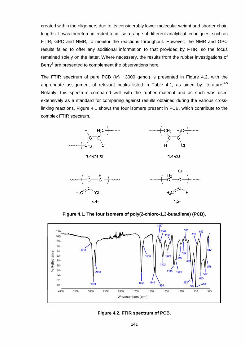
141
created within the oligomers due to its considerably lower molecular weight and shorter chain
lengths. It was therefore intended to utilise a range of different analytical techniques, such as
FTIR, GPC and NMR, to monitor the reactions throughout. However, the NMR and GPC
results failed to offer any additional information to that provided by FTIR, so the focus
remained solely on the latter. Where necessary, the results from the rubber investigations of
Berry1 are presented to complement the observations here.
The FTIR spectrum of pure PCB (Mn ~3000 g/mol) is presented in Figure 4.2, with the
appropriate assignment of relevant peaks listed in Table 4.1, as aided by literature.2-5
Notably, this spectrum compared well with the rubber material and as such was used
extensively as a standard for comparing against results obtained during the various cross-
linking reactions. Figure 4.1 shows the four isomers present in PCB, which contribute to the
complex FTIR spectrum.
Figure 4.1. The four isomers of poly(2-chloro-1,3-butadiene) (PCB).
Figure 4.2. FTIR spectrum of PCB.
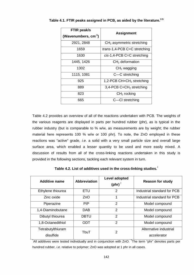
142
Table 4.1. FTIR peaks assigned in PCB, as aided by the literature.2-5
FTIR peak/s
(Wavenumbers, cm-1)Assignment
2921, 2848 CH2 asymmetric stretching
1659 trans-1,4-PCB C=C stretching
1630 cis-1,4-PCB C=C stretching
1445, 1426 CH2 deformation
1302 CH2 wagging
1115, 1081 C—C stretching
925 1,2-PCB CH=CH2 stretching
889 3,4-PCB C=CH2 stretching
823 CH2 rocking
665 C—Cl stretching
Table 4.2 provides an overview of all of the reactions undertaken with PCB. The weights of
the various reagents are displayed in parts per hundred rubber (phr), as is typical in the
rubber industry (but is comparable to % w/w, as measurements are by weight; the rubber
material here represents 100 % w/w or 100 phr). To note, the ZnO employed in these
reactions was “active” grade, i.e. a solid with a very small particle size and overall large
surface area, which enabled a lesser quantity to be used and more easily mixed. A
discussion of results from all of the cross-linking reactions undertaken in this study is
provided in the following sections, tackling each relevant system in turn.
Table 4.2. List of additives used in the cross-linking studies.*
Additive name AbbreviationLevel adopted
(phr) †Reason for study
Ethylene thiourea ETU 2 Industrial standard for PCB
Zinc oxide ZnO 1 Industrial standard for PCB
Piperazine PIP 2 Model compound
1,4-Diaminobutane DAB 2 Model compound
Dibutyl thiourea DBTU 2 Model compound
1,8-Octanedithiol ODT 2 Model compound
Tetrabutylthiuram
disulfideTbuT 2
Alternative industrial
accelerator*All additives were tested individually and in conjunction with ZnO.
†The term “phr” denotes parts per
hundred rubber, i.e. relative to polymer; ZnO was adopted at 1 phr in all cases.
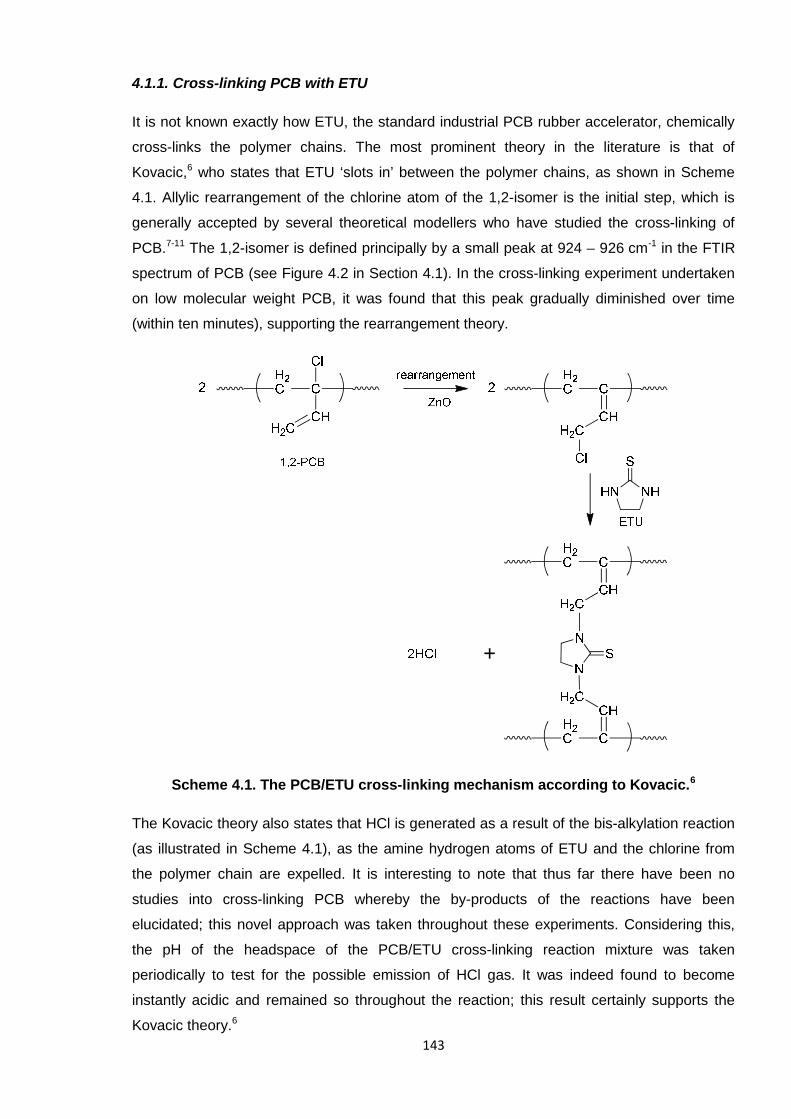
143
4.1.1. Cross-linking PCB with ETU
It is not known exactly how ETU, the standard industrial PCB rubber accelerator, chemically
cross-links the polymer chains. The most prominent theory in the literature is that of
Kovacic,6 who states that ETU ‘slots in’ between the polymer chains, as shown in Scheme
4.1. Allylic rearrangement of the chlorine atom of the 1,2-isomer is the initial step, which is
generally accepted by several theoretical modellers who have studied the cross-linking of
PCB.7-11 The 1,2-isomer is defined principally by a small peak at 924 – 926 cm-1 in the FTIR
spectrum of PCB (see Figure 4.2 in Section 4.1). In the cross-linking experiment undertaken
on low molecular weight PCB, it was found that this peak gradually diminished over time
(within ten minutes), supporting the rearrangement theory.
Scheme 4.1. The PCB/ETU cross-linking mechanism according to Kovacic.6
The Kovacic theory also states that HCl is generated as a result of the bis-alkylation reaction
(as illustrated in Scheme 4.1), as the amine hydrogen atoms of ETU and the chlorine from
the polymer chain are expelled. It is interesting to note that thus far there have been no
studies into cross-linking PCB whereby the by-products of the reactions have been
elucidated; this novel approach was taken throughout these experiments. Considering this,
the pH of the headspace of the PCB/ETU cross-linking reaction mixture was taken
periodically to test for the possible emission of HCl gas. It was indeed found to become
instantly acidic and remained so throughout the reaction; this result certainly supports the
Kovacic theory.6
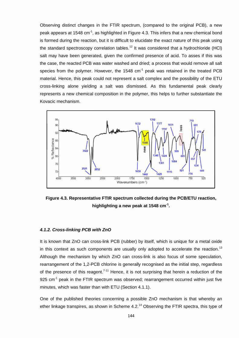
144
Observing distinct changes in the FTIR spectrum, (compared to the original PCB), a new
peak appears at 1548 cm-1, as highlighted in Figure 4.3. This infers that a new chemical bond
is formed during the reaction, but it is difficult to elucidate the exact nature of this peak using
the standard spectroscopy correlation tables.12 It was considered that a hydrochloride (HCl)
salt may have been generated, given the confirmed presence of acid. To asses if this was
the case, the reacted PCB was water washed and dried; a process that would remove all salt
species from the polymer. However, the 1548 cm-1 peak was retained in the treated PCB
material. Hence, this peak could not represent a salt complex and the possibility of the ETU
cross-linking alone yielding a salt was dismissed. As this fundamental peak clearly
represents a new chemical composition in the polymer, this helps to further substantiate the
Kovacic mechanism.
Figure 4.3. Representative FTIR spectrum collected during the PCB/ETU reaction,
highlighting a new peak at 1548 cm-1.
4.1.2. Cross-linking PCB with ZnO
It is known that ZnO can cross-link PCB (rubber) by itself, which is unique for a metal oxide
in this context as such components are usually only adopted to accelerate the reaction.13
Although the mechanism by which ZnO can cross-link is also focus of some speculation,
rearrangement of the 1,2-PCB chlorine is generally recognised as the initial step, regardless
of the presence of this reagent.7-11 Hence, it is not surprising that herein a reduction of the
925 cm-1 peak in the FTIR spectrum was observed; rearrangement occurred within just five
minutes, which was faster than with ETU (Section 4.1.1).
One of the published theories concerning a possible ZnO mechanism is that whereby an
ether linkage transpires, as shown in Scheme 4.2.14 Observing the FTIR spectra, this type of
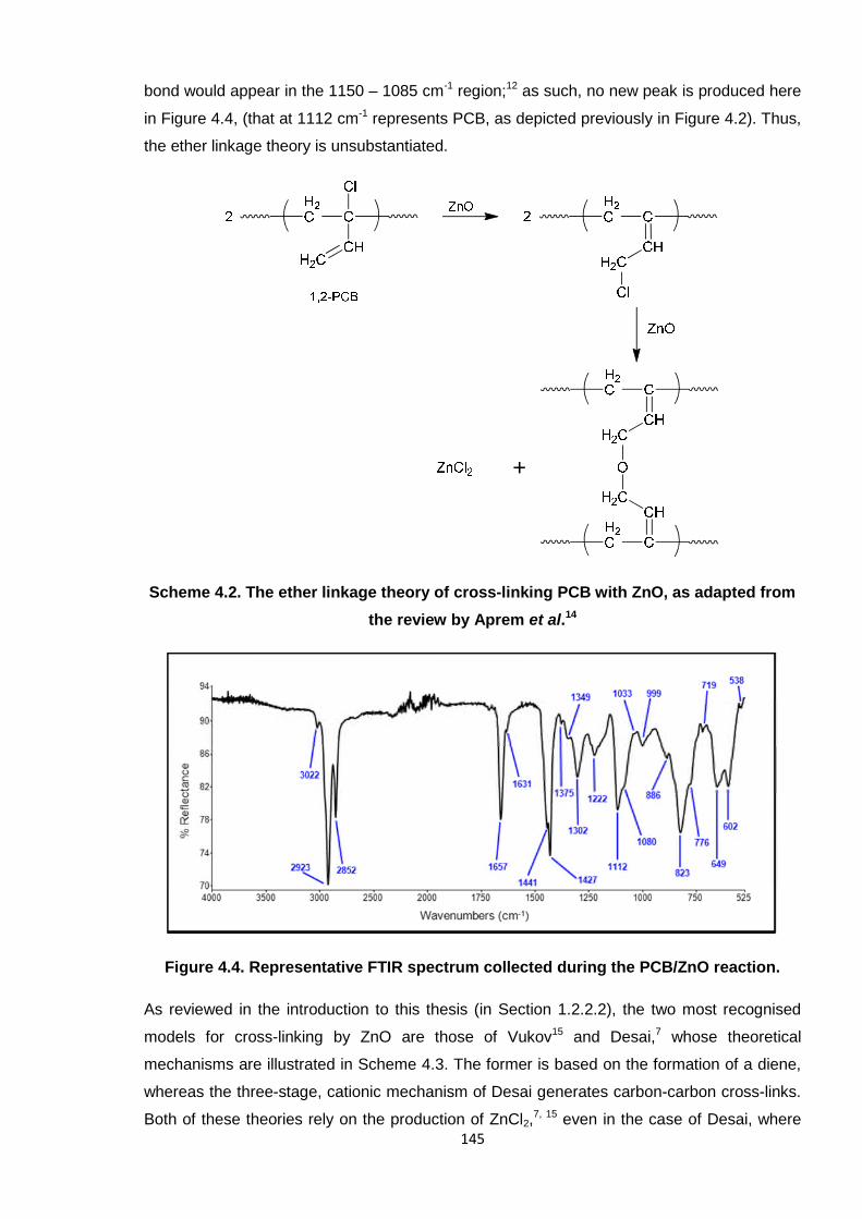
145
bond would appear in the 1150 – 1085 cm-1 region;12 as such, no new peak is produced here
in Figure 4.4, (that at 1112 cm-1 represents PCB, as depicted previously in Figure 4.2). Thus,
the ether linkage theory is unsubstantiated.
Scheme 4.2. The ether linkage theory of cross-linking PCB with ZnO, as adapted from
the review by Aprem et al.14
Figure 4.4. Representative FTIR spectrum collected during the PCB/ZnO reaction.
As reviewed in the introduction to this thesis (in Section 1.2.2.2), the two most recognised
models for cross-linking by ZnO are those of Vukov15 and Desai,7 whose theoretical
mechanisms are illustrated in Scheme 4.3. The former is based on the formation of a diene,
whereas the three-stage, cationic mechanism of Desai generates carbon-carbon cross-links.
Both of these theories rely on the production of ZnCl2,7, 15 even in the case of Desai, where
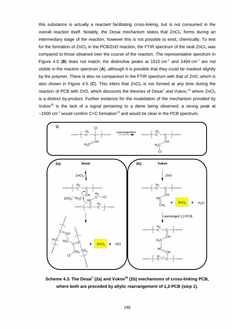
146
this substance is actually a reactant facilitating cross-linking, but is not consumed in the
overall reaction itself. Notably, the Desai mechanism states that ZnCl3- forms during an
intermediary stage of the reaction, however this is not possible to exist, chemically. To test
for the formation of ZnCl2 in the PCB/ZnO reaction, the FTIR spectrum of the neat ZnCl2 was
compared to those obtained over the course of the reaction. The representative spectrum in
Figure 4.5 (B) does not match; the distinctive peaks at 1615 cm-1 and 1404 cm-1 are not
visible in the reaction spectrum (A), although it is possible that they could be masked slightly
by the polymer. There is also no comparison in the FTIR spectrum with that of ZnO, which is
also shown in Figure 4.5 (C). This infers that ZnCl2 is not formed at any time during the
reaction of PCB with ZnO, which discounts the theories of Desai7 and Vukov,15 where ZnCl2
is a distinct by-product. Further evidence for the invalidation of the mechanism provided by
Vukov15 is the lack of a signal pertaining to a diene being observed; a strong peak at
~1600 cm-1 would confirm C=C formation12 and would be clear in the PCB spectrum.
Scheme 4.3. The Desai7 (2a) and Vukov15 (2b) mechanisms of cross-linking PCB,
where both are preceded by allylic rearrangement of 1,2-PCB (step 1).
ZnCl2
H2C C
CH+H2CZnCl3
-
H2CC
HC
H2C Cl
H2C
CCH
H2C
CH2
CC
CH2
Cl
ZnCl2 HCl
H2C C
CHH2C
ClH2C C
CHH2C
Cl
rearrangement
ZnO
H2C C
CHHC
CH2
ZnCl2 H2O
rearranged 1,2-PCB
H2C C
CHH2C
HC C
CHHC
Desai Vukov
1)
2a) 2b)
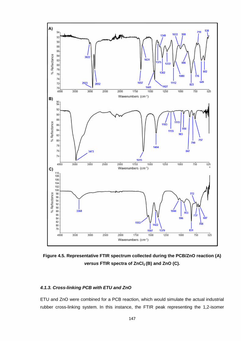
147
Figure 4.5. Representative FTIR spectrum collected during the PCB/ZnO reaction (A)
versus FTIR spectra of ZnCl2 (B) and ZnO (C).
4.1.3. Cross-linking PCB with ETU and ZnO
ETU and ZnO were combined for a PCB reaction, which would simulate the actual industrial
rubber cross-linking system. In this instance, the FTIR peak representing the 1,2-isomer
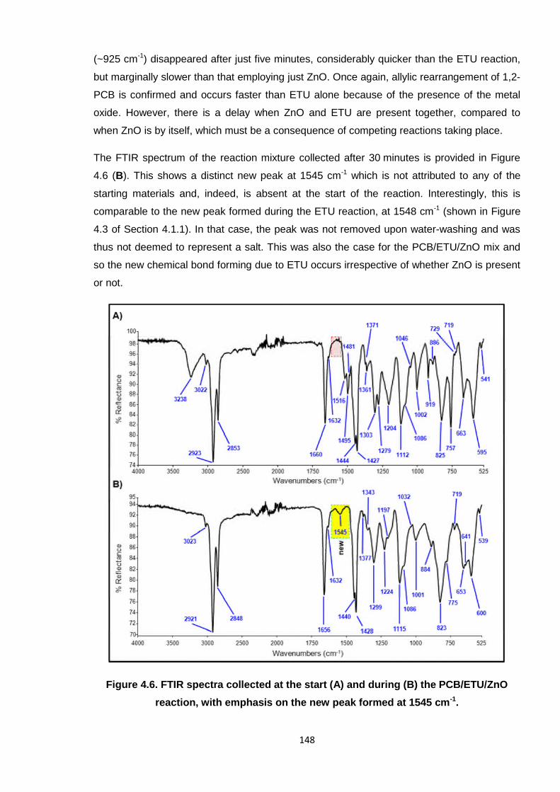
148
(~925 cm-1) disappeared after just five minutes, considerably quicker than the ETU reaction,
but marginally slower than that employing just ZnO. Once again, allylic rearrangement of 1,2-
PCB is confirmed and occurs faster than ETU alone because of the presence of the metal
oxide. However, there is a delay when ZnO and ETU are present together, compared to
when ZnO is by itself, which must be a consequence of competing reactions taking place.
The FTIR spectrum of the reaction mixture collected after 30 minutes is provided in Figure
4.6 (B). This shows a distinct new peak at 1545 cm-1 which is not attributed to any of the
starting materials and, indeed, is absent at the start of the reaction. Interestingly, this is
comparable to the new peak formed during the ETU reaction, at 1548 cm-1 (shown in Figure
4.3 of Section 4.1.1). In that case, the peak was not removed upon water-washing and was
thus not deemed to represent a salt. This was also the case for the PCB/ETU/ZnO mix and
so the new chemical bond forming due to ETU occurs irrespective of whether ZnO is present
or not.
Figure 4.6. FTIR spectra collected at the start (A) and during (B) the PCB/ETU/ZnO
reaction, with emphasis on the new peak formed at 1545 cm-1.
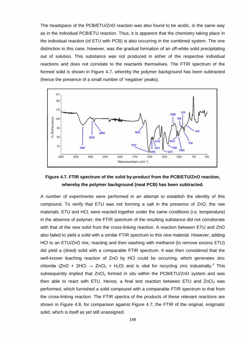
149
The headspace of the PCB/ETU/ZnO reaction was also found to be acidic, in the same way
as in the individual PCB/ETU reaction. Thus, it is apparent that the chemistry taking place in
the individual reaction (of ETU with PCB) is also occurring in the combined system. The one
distinction in this case, however, was the gradual formation of an off-white solid precipitating
out of solution. This substance was not produced in either of the respective individual
reactions and does not correlate to the reactants themselves. The FTIR spectrum of the
formed solid is shown in Figure 4.7, whereby the polymer background has been subtracted
(hence the presence of a small number of ‘negative’ peaks).
Figure 4.7. FTIR spectrum of the solid by-product from the PCB/ETU/ZnO reaction,
whereby the polymer background (neat PCB) has been subtracted.
A number of experiments were performed in an attempt to establish the identity of this
compound. To verify that ETU was not forming a salt in the presence of ZnO, the raw
materials, ETU and HCl, were reacted together under the same conditions (i.e. temperature)
in the absence of polymer; the FTIR spectrum of the resulting substance did not corroborate
with that of the new solid from the cross-linking reaction. A reaction between ETU and ZnO
also failed to yield a solid with a similar FTIR spectrum to this new material. However, adding
HCl to an ETU/ZnO mix, reacting and then washing with methanol (to remove excess ETU)
did yield a (dried) solid with a comparable FTIR spectrum. It was then considered that the
well-known leaching reaction of ZnO by HCl could be occurring, which generates zinc
chloride (ZnO + 2HCl → ZnCl2 + H2O) and is vital for recycling zinc industrially.4 This
subsequently implied that ZnCl2 formed in situ within the PCB/ETU/ZnO system and was
then able to react with ETU. Hence, a final test reaction between ETU and ZnCl2 was
performed, which furnished a solid compound with a comparable FTIR spectrum to that from
the cross-linking reaction. The FTIR spectra of the products of these relevant reactions are
shown in Figure 4.8, for comparison against Figure 4.7, the FTIR of the original, enigmatic
solid, which is itself as yet still unassigned.
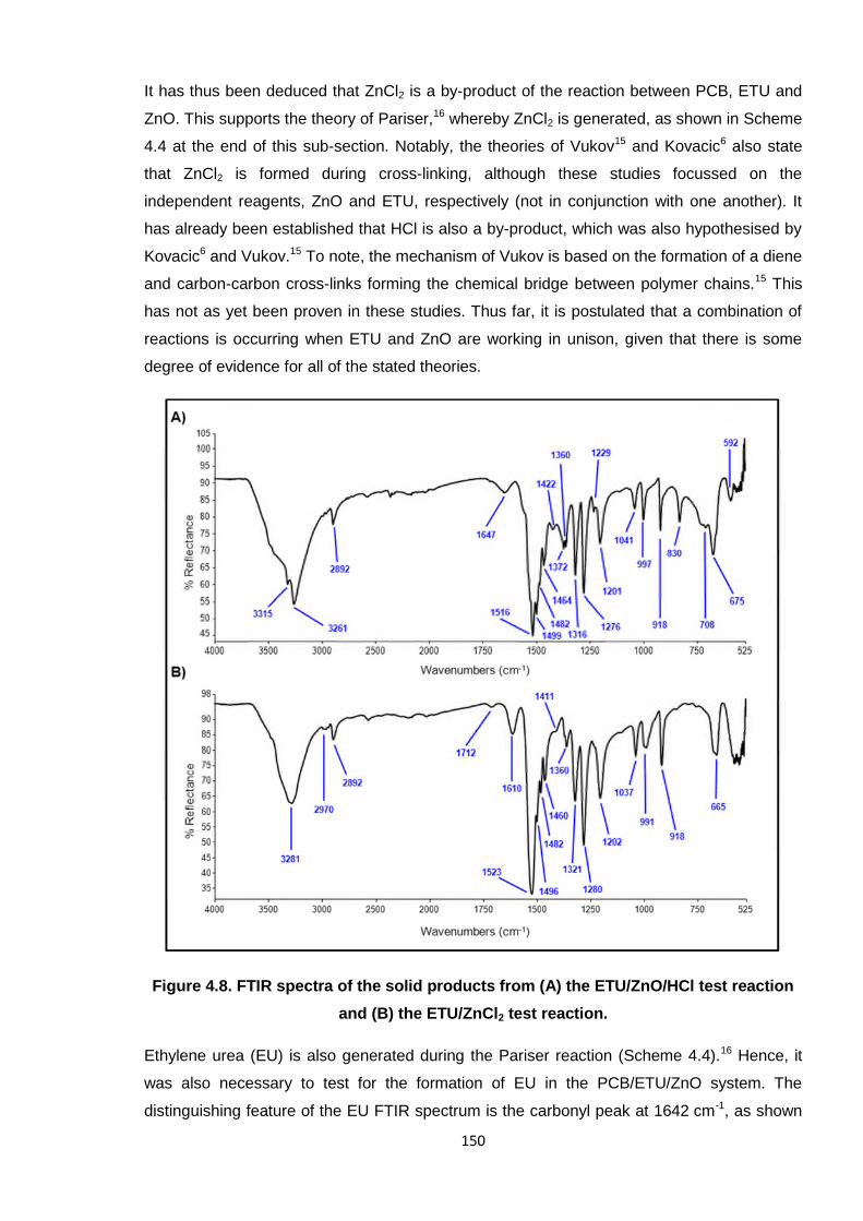
150
It has thus been deduced that ZnCl2 is a by-product of the reaction between PCB, ETU and
ZnO. This supports the theory of Pariser,16 whereby ZnCl2 is generated, as shown in Scheme
4.4 at the end of this sub-section. Notably, the theories of Vukov15 and Kovacic6 also state
that ZnCl2 is formed during cross-linking, although these studies focussed on the
independent reagents, ZnO and ETU, respectively (not in conjunction with one another). It
has already been established that HCl is also a by-product, which was also hypothesised by
Kovacic6 and Vukov.15 To note, the mechanism of Vukov is based on the formation of a diene
and carbon-carbon cross-links forming the chemical bridge between polymer chains.15 This
has not as yet been proven in these studies. Thus far, it is postulated that a combination of
reactions is occurring when ETU and ZnO are working in unison, given that there is some
degree of evidence for all of the stated theories.
Figure 4.8. FTIR spectra of the solid products from (A) the ETU/ZnO/HCl test reaction
and (B) the ETU/ZnCl2 test reaction.
Ethylene urea (EU) is also generated during the Pariser reaction (Scheme 4.4).16 Hence, it
was also necessary to test for the formation of EU in the PCB/ETU/ZnO system. The
distinguishing feature of the EU FTIR spectrum is the carbonyl peak at 1642 cm-1, as shown
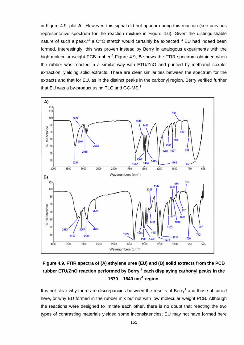
151
in Figure 4.9, plot A. However, this signal did not appear during this reaction (see previous
representative spectrum for the reaction mixture in Figure 4.6). Given the distinguishable
nature of such a peak,12 a C=O stretch would certainly be expected if EU had indeed been
formed. Interestingly, this was proven instead by Berry in analogous experiments with the
high molecular weight PCB rubber.1 Figure 4.9, B shows the FTIR spectrum obtained when
the rubber was reacted in a similar way with ETU/ZnO and purified by methanol soxhlet
extraction, yielding solid extracts. There are clear similarities between the spectrum for the
extracts and that for EU, as in the distinct peaks in the carbonyl region. Berry verified further
that EU was a by-product using TLC and GC-MS.1
Figure 4.9. FTIR spectra of (A) ethylene urea (EU) and (B) solid extracts from the PCB
rubber ETU/ZnO reaction performed by Berry,1 each displaying carbonyl peaks in the
1670 – 1640 cm-1 region.
It is not clear why there are discrepancies between the results of Berry1 and those obtained
here, or why EU formed in the rubber mix but not with low molecular weight PCB. Although
the reactions were designed to imitate each other, there is no doubt that reacting the two
types of contrasting materials yielded some inconsistencies; EU may not have formed here
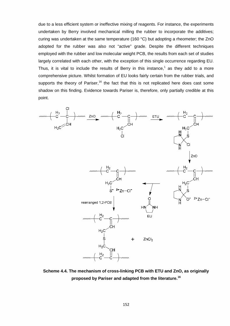
152
due to a less efficient system or ineffective mixing of reagents. For instance, the experiments
undertaken by Berry involved mechanical milling the rubber to incorporate the additives;
curing was undertaken at the same temperature (160 °C) but adopting a rheometer; the ZnO
adopted for the rubber was also not “active” grade. Despite the different techniques
employed with the rubber and low molecular weight PCB, the results from each set of studies
largely correlated with each other, with the exception of this single occurrence regarding EU.
Thus, it is vital to include the results of Berry in this instance,1 as they add to a more
comprehensive picture. Whilst formation of EU looks fairly certain from the rubber trials, and
supports the theory of Pariser,16 the fact that this is not replicated here does cast some
shadow on this finding. Evidence towards Pariser is, therefore, only partially credible at this
point.
Scheme 4.4. The mechanism of cross-linking PCB with ETU and ZnO, as originally
proposed by Pariser and adapted from the literature.16
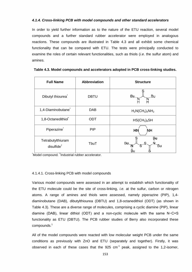
153
4.1.4. Cross-linking PCB with model compounds and other standard accelerators
In order to yield further information as to the nature of the ETU reaction, several model
compounds and a further standard rubber accelerator were employed in analogous
reactions. These compounds are illustrated in Table 4.3 and all exhibit some chemical
functionality that can be compared with ETU. The tests were principally conducted to
examine the roles of certain relevant functionalities, such as thiols (i.e. the sulfur atom) and
amines.
Table 4.3. Model compounds and accelerators adopted in PCB cross-linking studies.
Full Name Abbreviation Structure
Dibutyl thiourea* DBTU
1,4-Diaminobutane* DAB H2N(CH2)4NH2
1,8-Octanedithiol* ODT HS(CH2)8SH
Piperazine* PIP
Tetrabutylthiuram
disulfide†TbuT
*Model compound.
†Industrial rubber accelerator.
4.1.4.1. Cross-linking PCB with model compounds
Various model compounds were assessed in an attempt to establish which functionality of
the ETU molecule could be the site of cross-linking, i.e. at the sulfur, carbon or nitrogen
atoms. A range of amines and thiols were assessed, namely piperazine (PIP), 1,4-
diaminobutane (DAB), dibutylthiourea (DBTU) and 1,8-octanedithiol (ODT) (as shown in
Table 4.3). These are a diverse range of molecules, comprising a cyclic diamine (PIP), linear
diamine (DAB), linear dithiol (ODT) and a non-cyclic molecule with the same N−C=S
functionality as ETU (DBTU). The PCB rubber studies of Berry also incorporated these
compounds.1
All of the model compounds were reacted with low molecular weight PCB under the same
conditions as previously with ZnO and ETU (separately and together). Firstly, it was
observed in each of these cases that the 925 cm-1 peak, assigned to the 1,2-isomer,
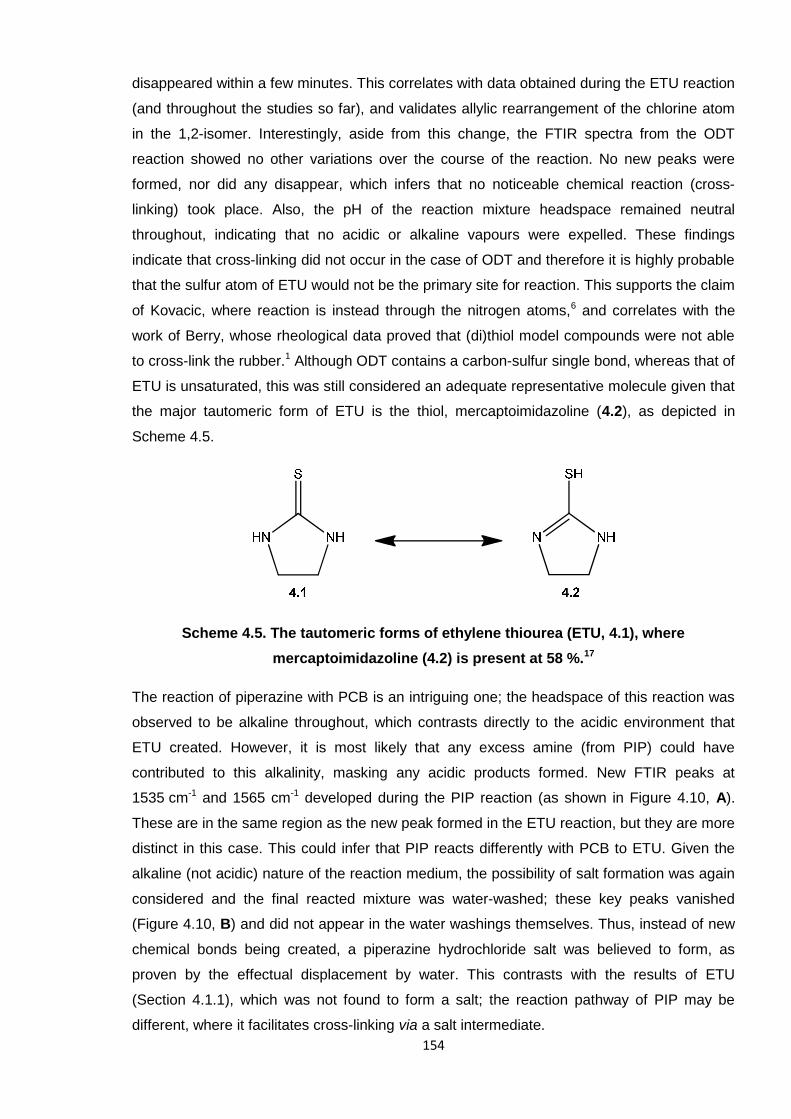
154
disappeared within a few minutes. This correlates with data obtained during the ETU reaction
(and throughout the studies so far), and validates allylic rearrangement of the chlorine atom
in the 1,2-isomer. Interestingly, aside from this change, the FTIR spectra from the ODT
reaction showed no other variations over the course of the reaction. No new peaks were
formed, nor did any disappear, which infers that no noticeable chemical reaction (cross-
linking) took place. Also, the pH of the reaction mixture headspace remained neutral
throughout, indicating that no acidic or alkaline vapours were expelled. These findings
indicate that cross-linking did not occur in the case of ODT and therefore it is highly probable
that the sulfur atom of ETU would not be the primary site for reaction. This supports the claim
of Kovacic, where reaction is instead through the nitrogen atoms,6 and correlates with the
work of Berry, whose rheological data proved that (di)thiol model compounds were not able
to cross-link the rubber.1 Although ODT contains a carbon-sulfur single bond, whereas that of
ETU is unsaturated, this was still considered an adequate representative molecule given that
the major tautomeric form of ETU is the thiol, mercaptoimidazoline (4.2), as depicted in
Scheme 4.5.
Scheme 4.5. The tautomeric forms of ethylene thiourea (ETU, 4.1), where
mercaptoimidazoline (4.2) is present at 58 %.17
The reaction of piperazine with PCB is an intriguing one; the headspace of this reaction was
observed to be alkaline throughout, which contrasts directly to the acidic environment that
ETU created. However, it is most likely that any excess amine (from PIP) could have
contributed to this alkalinity, masking any acidic products formed. New FTIR peaks at
1535 cm-1 and 1565 cm-1 developed during the PIP reaction (as shown in Figure 4.10, A).
These are in the same region as the new peak formed in the ETU reaction, but they are more
distinct in this case. This could infer that PIP reacts differently with PCB to ETU. Given the
alkaline (not acidic) nature of the reaction medium, the possibility of salt formation was again
considered and the final reacted mixture was water-washed; these key peaks vanished
(Figure 4.10, B) and did not appear in the water washings themselves. Thus, instead of new
chemical bonds being created, a piperazine hydrochloride salt was believed to form, as
proven by the effectual displacement by water. This contrasts with the results of ETU
(Section 4.1.1), which was not found to form a salt; the reaction pathway of PIP may be
different, where it facilitates cross-linking via a salt intermediate.
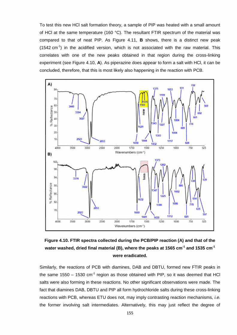
155
To test this new HCl salt formation theory, a sample of PIP was heated with a small amount
of HCl at the same temperature (160 °C). The resultant FTIR spectrum of the material was
compared to that of neat PIP. As Figure 4.11, B shows, there is a distinct new peak
(1542 cm-1) in the acidified version, which is not associated with the raw material. This
correlates with one of the new peaks obtained in that region during the cross-linking
experiment (see Figure 4.10, A). As piperazine does appear to form a salt with HCl, it can be
concluded, therefore, that this is most likely also happening in the reaction with PCB.
Figure 4.10. FTIR spectra collected during the PCB/PIP reaction (A) and that of the
water washed, dried final material (B), where the peaks at 1565 cm-1 and 1535 cm-1
were eradicated.
Similarly, the reactions of PCB with diamines, DAB and DBTU, formed new FTIR peaks in
the same 1550 – 1530 cm-1 region as those obtained with PIP, so it was deemed that HCl
salts were also forming in these reactions. No other significant observations were made. The
fact that diamines DAB, DBTU and PIP all form hydrochloride salts during these cross-linking
reactions with PCB, whereas ETU does not, may imply contrasting reaction mechanisms, i.e.
the former involving salt intermediates. Alternatively, this may just reflect the degree of
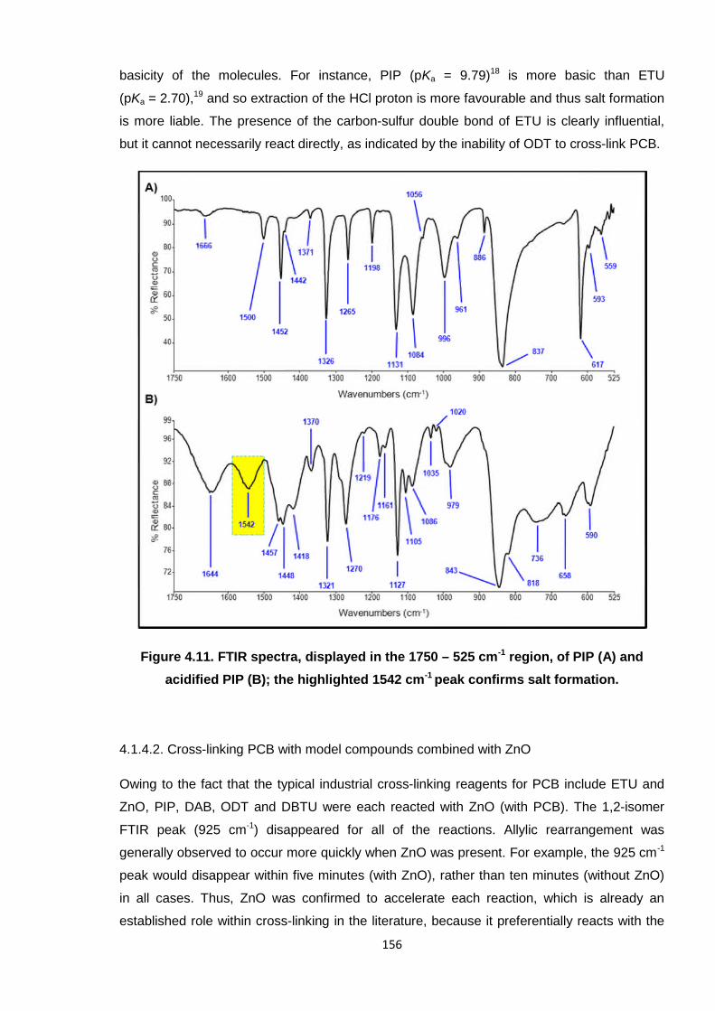
156
basicity of the molecules. For instance, PIP (pKa = 9.79)18 is more basic than ETU
(pKa = 2.70),19 and so extraction of the HCl proton is more favourable and thus salt formation
is more liable. The presence of the carbon-sulfur double bond of ETU is clearly influential,
but it cannot necessarily react directly, as indicated by the inability of ODT to cross-link PCB.
Figure 4.11. FTIR spectra, displayed in the 1750 – 525 cm-1 region, of PIP (A) and
acidified PIP (B); the highlighted 1542 cm-1 peak confirms salt formation.
4.1.4.2. Cross-linking PCB with model compounds combined with ZnO
Owing to the fact that the typical industrial cross-linking reagents for PCB include ETU and
ZnO, PIP, DAB, ODT and DBTU were each reacted with ZnO (with PCB). The 1,2-isomer
FTIR peak (925 cm-1) disappeared for all of the reactions. Allylic rearrangement was
generally observed to occur more quickly when ZnO was present. For example, the 925 cm-1
peak would disappear within five minutes (with ZnO), rather than ten minutes (without ZnO)
in all cases. Thus, ZnO was confirmed to accelerate each reaction, which is already an
established role within cross-linking in the literature, because it preferentially reacts with the
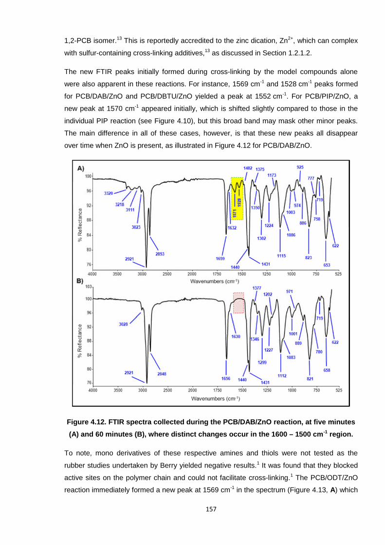
157
1,2-PCB isomer.13 This is reportedly accredited to the zinc dication, Zn2+, which can complex
with sulfur-containing cross-linking additives,13 as discussed in Section 1.2.1.2.
The new FTIR peaks initially formed during cross-linking by the model compounds alone
were also apparent in these reactions. For instance, 1569 cm-1 and 1528 cm-1 peaks formed
for PCB/DAB/ZnO and PCB/DBTU/ZnO yielded a peak at 1552 cm-1. For PCB/PIP/ZnO, a
new peak at 1570 cm-1 appeared initially, which is shifted slightly compared to those in the
individual PIP reaction (see Figure 4.10), but this broad band may mask other minor peaks.
The main difference in all of these cases, however, is that these new peaks all disappear
over time when ZnO is present, as illustrated in Figure 4.12 for PCB/DAB/ZnO.
Figure 4.12. FTIR spectra collected during the PCB/DAB/ZnO reaction, at five minutes
(A) and 60 minutes (B), where distinct changes occur in the 1600 – 1500 cm-1 region.
To note, mono derivatives of these respective amines and thiols were not tested as the
rubber studies undertaken by Berry yielded negative results.1 It was found that they blocked
active sites on the polymer chain and could not facilitate cross-linking.1 The PCB/ODT/ZnO
reaction immediately formed a new peak at 1569 cm-1 in the spectrum (Figure 4.13, A) which
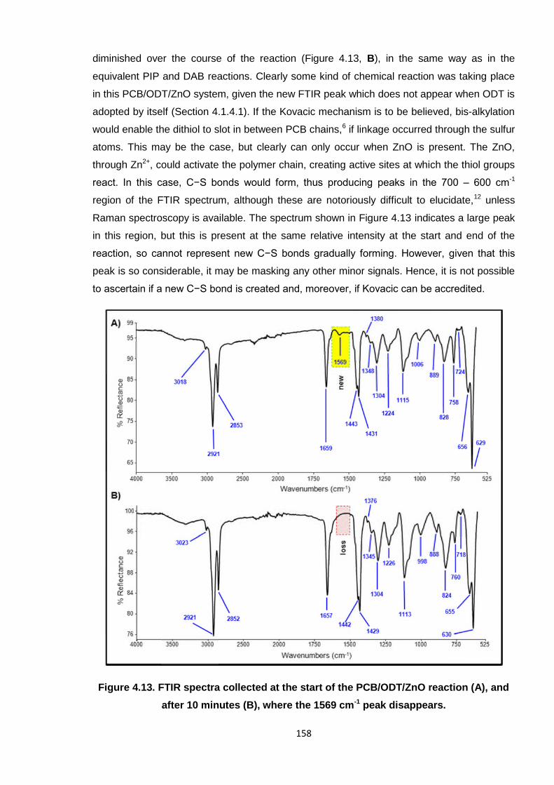
158
diminished over the course of the reaction (Figure 4.13, B), in the same way as in the
equivalent PIP and DAB reactions. Clearly some kind of chemical reaction was taking place
in this PCB/ODT/ZnO system, given the new FTIR peak which does not appear when ODT is
adopted by itself (Section 4.1.4.1). If the Kovacic mechanism is to be believed, bis-alkylation
would enable the dithiol to slot in between PCB chains,6 if linkage occurred through the sulfur
atoms. This may be the case, but clearly can only occur when ZnO is present. The ZnO,
through Zn2+, could activate the polymer chain, creating active sites at which the thiol groups
react. In this case, C−S bonds would form, thus producing peaks in the 700 – 600 cm-1
region of the FTIR spectrum, although these are notoriously difficult to elucidate,12 unless
Raman spectroscopy is available. The spectrum shown in Figure 4.13 indicates a large peak
in this region, but this is present at the same relative intensity at the start and end of the
reaction, so cannot represent new C−S bonds gradually forming. However, given that this
peak is so considerable, it may be masking any other minor signals. Hence, it is not possible
to ascertain if a new C−S bond is created and, moreover, if Kovacic can be accredited.
Figure 4.13. FTIR spectra collected at the start of the PCB/ODT/ZnO reaction (A), and
after 10 minutes (B), where the 1569 cm-1 peak disappears.
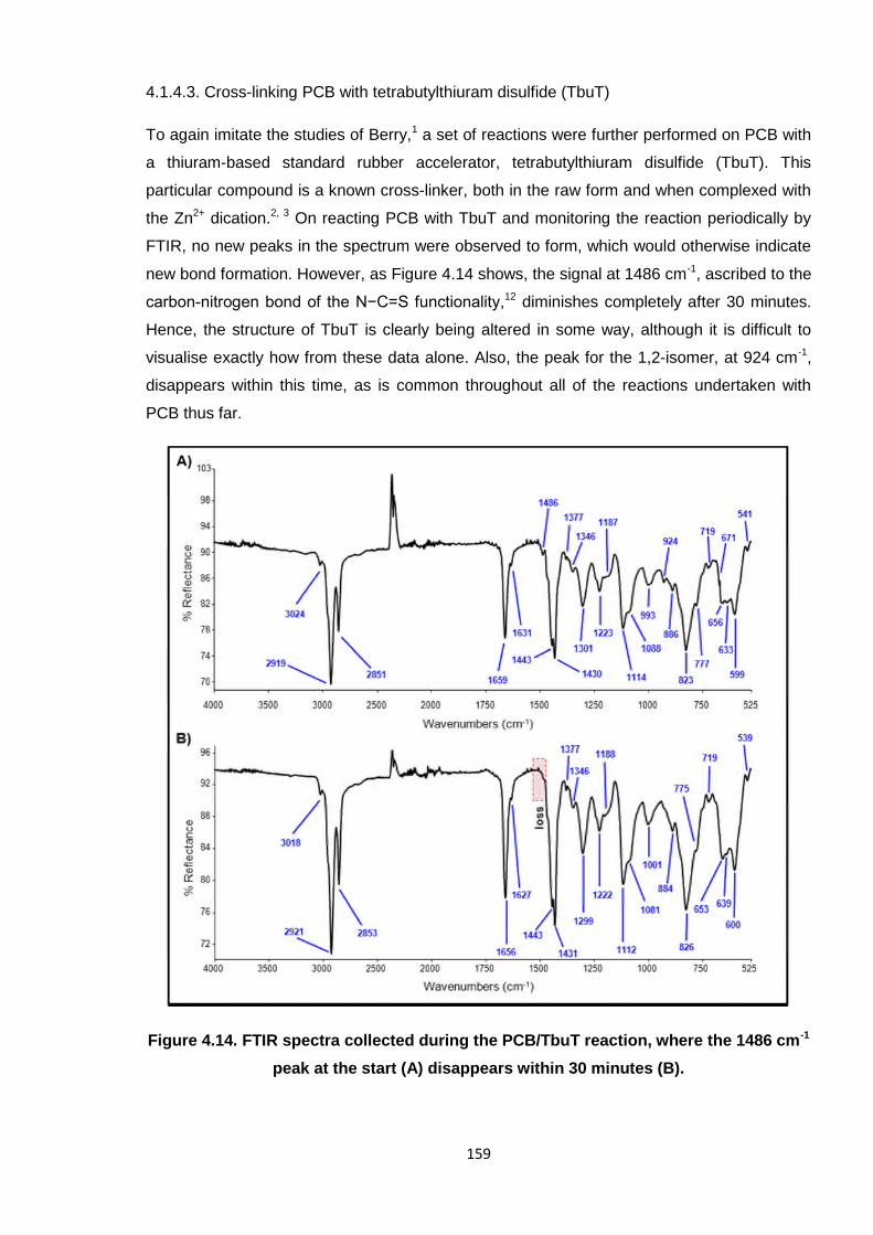
159
4.1.4.3. Cross-linking PCB with tetrabutylthiuram disulfide (TbuT)
To again imitate the studies of Berry,1 a set of reactions were further performed on PCB with
a thiuram-based standard rubber accelerator, tetrabutylthiuram disulfide (TbuT). This
particular compound is a known cross-linker, both in the raw form and when complexed with
the Zn2+ dication.2, 3 On reacting PCB with TbuT and monitoring the reaction periodically by
FTIR, no new peaks in the spectrum were observed to form, which would otherwise indicate
new bond formation. However, as Figure 4.14 shows, the signal at 1486 cm-1, ascribed to the
carbon-nitrogen bond of the N−C=S functionality,12 diminishes completely after 30 minutes.
Hence, the structure of TbuT is clearly being altered in some way, although it is difficult to
visualise exactly how from these data alone. Also, the peak for the 1,2-isomer, at 924 cm-1,
disappears within this time, as is common throughout all of the reactions undertaken with
PCB thus far.
Figure 4.14. FTIR spectra collected during the PCB/TbuT reaction, where the 1486 cm-1
peak at the start (A) disappears within 30 minutes (B).
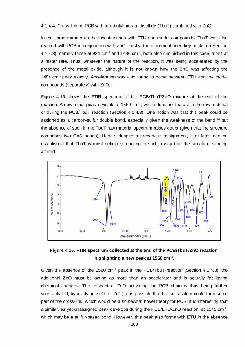
160
4.1.4.4. Cross-linking PCB with tetrabutylthiuram disulfide (TbuT) combined with ZnO
In the same manner as the investigations with ETU and model compounds, TbuT was also
reacted with PCB in conjunction with ZnO. Firstly, the aforementioned key peaks (in Section
4.1.4.3), namely those at 924 cm-1 and 1486 cm-1, both also diminished in this case, albeit at
a faster rate. Thus, whatever the nature of the reaction, it was being accelerated by the
presence of the metal oxide, although it is not known how the ZnO was affecting the
1484 cm-1 peak exactly. Acceleration was also found to occur between ETU and the model
compounds (separately) with ZnO.
Figure 4.15 shows the FTIR spectrum of the PCB/TbuT/ZnO mixture at the end of the
reaction. A new minor peak is visible at 1560 cm-1, which does not feature in the raw material
or during the PCB/TbuT reaction (Section 4.1.4.3). One notion was that this peak could be
assigned as a carbon-sulfur double bond, especially given the weakness of the band,12 but
the absence of such in the TbuT raw material spectrum raises doubt (given that the structure
comprises two C=S bonds). Hence, despite a precarious assignment, it at least can be
established that TbuT is most definitely reacting in such a way that the structure is being
altered.
Figure 4.15. FTIR spectrum collected at the end of the PCB/TbuT/ZnO reaction,
highlighting a new peak at 1560 cm-1.
Given the absence of the 1560 cm-1 peak in the PCB/TbuT reaction (Section 4.1.4.3), the
additional ZnO must be acting as more than an accelerator and is actually facilitating
chemical changes. The concept of ZnO activating the PCB chain is thus being further
substantiated; by involving ZnO (or Zn2+), it is possible that the sulfur atom could form some
part of the cross-link, which would be a somewhat novel theory for PCB. It is interesting that
a similar, as yet unassigned peak develops during the PCB/ETU/ZnO reaction, at 1545 cm-1,
which may be a sulfur-based bond. However, this peak also forms with ETU in the absence
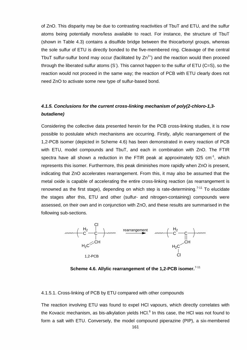
161
of ZnO. This disparity may be due to contrasting reactivities of TbuT and ETU, and the sulfur
atoms being potentially more/less available to react. For instance, the structure of TbuT
(shown in Table 4.3) contains a disulfide bridge between the thiocarbonyl groups, whereas
the sole sulfur of ETU is directly bonded to the five-membered ring. Cleavage of the central
TbuT sulfur-sulfur bond may occur (facilitated by Zn2+) and the reaction would then proceed
through the liberated sulfur atoms (S-). This cannot happen to the sulfur of ETU (C=S), so the
reaction would not proceed in the same way; the reaction of PCB with ETU clearly does not
need ZnO to activate some new type of sulfur-based bond.
4.1.5. Conclusions for the current cross-linking mechanism of poly(2-chloro-1,3-
butadiene)
Considering the collective data presented herein for the PCB cross-linking studies, it is now
possible to postulate which mechanisms are occurring. Firstly, allylic rearrangement of the
1,2-PCB isomer (depicted in Scheme 4.6) has been demonstrated in every reaction of PCB
with ETU, model compounds and TbuT, and each in combination with ZnO. The FTIR
spectra have all shown a reduction in the FTIR peak at approximately 925 cm-1, which
represents this isomer. Furthermore, this peak diminishes more rapidly when ZnO is present,
indicating that ZnO accelerates rearrangement. From this, it may also be assumed that the
metal oxide is capable of accelerating the entire cross-linking reaction (as rearrangement is
renowned as the first stage), depending on which step is rate-determining.7-11 To elucidate
the stages after this, ETU and other (sulfur- and nitrogen-containing) compounds were
assessed, on their own and in conjunction with ZnO, and these results are summarised in the
following sub-sections.
Scheme 4.6. Allylic rearrangement of the 1,2-PCB isomer.7-11
4.1.5.1. Cross-linking of PCB by ETU compared with other compounds
The reaction involving ETU was found to expel HCl vapours, which directly correlates with
the Kovacic mechanism, as bis-alkylation yields HCl.6 In this case, the HCl was not found to
form a salt with ETU. Conversely, the model compound piperazine (PIP), a six-membered
H2C C
CHH2C
ClH2C C
CHH2C
Cl
rearrangement
1,2-PCB
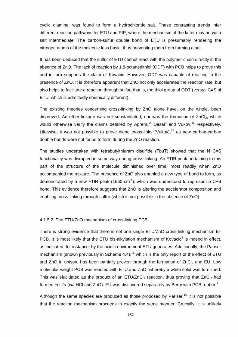
162
cyclic diamine, was found to form a hydrochloride salt. These contrasting trends infer
different reaction pathways for ETU and PIP, where the mechanism of the latter may be via a
salt intermediate. The carbon-sulfur double bond of ETU is presumably rendering the
nitrogen atoms of the molecule less basic, thus preventing them from forming a salt.
It has been deduced that the sulfur of ETU cannot react with the polymer chain directly in the
absence of ZnO. The lack of reaction by 1,8-octanedithiol (ODT) with PCB helps to prove this
and in turn supports the claim of Kovacic. However, ODT was capable of reacting in the
presence of ZnO. It is therefore apparent that ZnO not only accelerates the reaction rate, but
also helps to facilitate a reaction through sulfur, that is, the thiol group of ODT (versus C=S of
ETU, which is admittedly chemically different).
The existing theories concerning cross-linking by ZnO alone have, on the whole, been
disproved. An ether linkage was not substantiated, nor was the formation of ZnCl2, which
would otherwise verify the claims detailed by Aprem,14 Desai7 and Vukov,15 respectively.
Likewise, it was not possible to prove diene cross-links (Vukov),15 as new carbon-carbon
double bonds were not found to form during the ZnO reaction.
The studies undertaken with tetrabutylthiuram disulfide (TbuT) showed that the N−C=S
functionality was disrupted in some way during cross-linking. An FTIR peak pertaining to this
part of the structure of the molecule diminished over time, most readily when ZnO
accompanied the mixture. The presence of ZnO also enabled a new type of bond to form, as
demonstrated by a new FTIR peak (1560 cm-1), which was understood to represent a C−S
bond. This evidence therefore suggests that ZnO is altering the accelerator composition and
enabling cross-linking through sulfur (which is not possible in the absence of ZnO).
4.1.5.2. The ETU/ZnO mechanism of cross-linking PCB
There is strong evidence that there is not one single ETU/ZnO cross-linking mechanism for
PCB. It is most likely that the ETU bis-alkylation mechanism of Kovacic6 is indeed in effect,
as indicated, for instance, by the acidic environment ETU generates. Additionally, the Pariser
mechanism (shown previously in Scheme 4.4),16 which is the only report of the effect of ETU
and ZnO in unison, has been partially proven through the formation of ZnCl2 and EU. Low
molecular weight PCB was reacted with ETU and ZnO, whereby a white solid was furnished.
This was elucidated as the product of an ETU/ZnCl2 reaction, thus proving that ZnCl2 had
formed in situ (via HCl and ZnO). EU was discovered separately by Berry with PCB rubber.1
Although the same species are produced as those proposed by Pariser,16 it is not possible
that the reaction mechanism proceeds in exactly the same manner. Crucially, it is unlikely
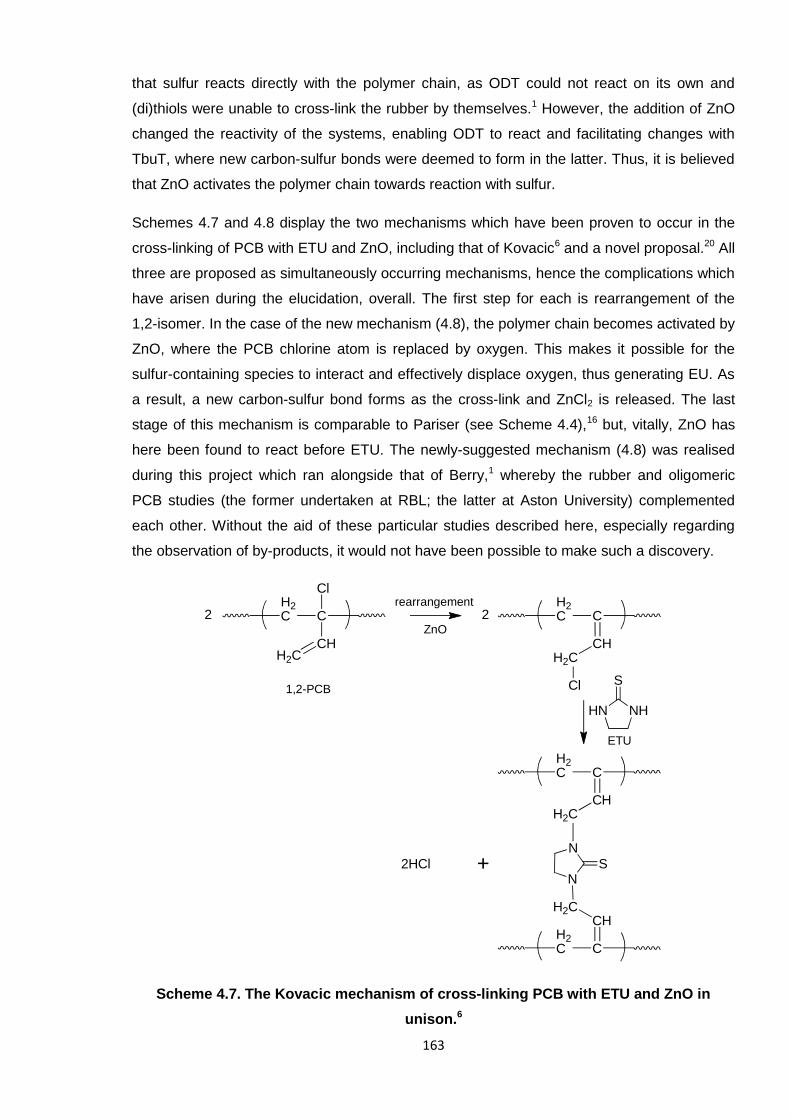
163
that sulfur reacts directly with the polymer chain, as ODT could not react on its own and
(di)thiols were unable to cross-link the rubber by themselves.1 However, the addition of ZnO
changed the reactivity of the systems, enabling ODT to react and facilitating changes with
TbuT, where new carbon-sulfur bonds were deemed to form in the latter. Thus, it is believed
that ZnO activates the polymer chain towards reaction with sulfur.
Schemes 4.7 and 4.8 display the two mechanisms which have been proven to occur in the
cross-linking of PCB with ETU and ZnO, including that of Kovacic6 and a novel proposal.20 All
three are proposed as simultaneously occurring mechanisms, hence the complications which
have arisen during the elucidation, overall. The first step for each is rearrangement of the
1,2-isomer. In the case of the new mechanism (4.8), the polymer chain becomes activated by
ZnO, where the PCB chlorine atom is replaced by oxygen. This makes it possible for the
sulfur-containing species to interact and effectively displace oxygen, thus generating EU. As
a result, a new carbon-sulfur bond forms as the cross-link and ZnCl2 is released. The last
stage of this mechanism is comparable to Pariser (see Scheme 4.4),16 but, vitally, ZnO has
here been found to react before ETU. The newly-suggested mechanism (4.8) was realised
during this project which ran alongside that of Berry,1 whereby the rubber and oligomeric
PCB studies (the former undertaken at RBL; the latter at Aston University) complemented
each other. Without the aid of these particular studies described here, especially regarding
the observation of by-products, it would not have been possible to make such a discovery.
Scheme 4.7. The Kovacic mechanism of cross-linking PCB with ETU and ZnO in
unison.6
H2C C
CHH2C
H2C C
CHH2C
N
NS
H2C C
CHH2C
ClH2C C
CHH2C
Cl1,2-PCB
NHHN
S
2HCl
22rearrangement
ZnO
ETU
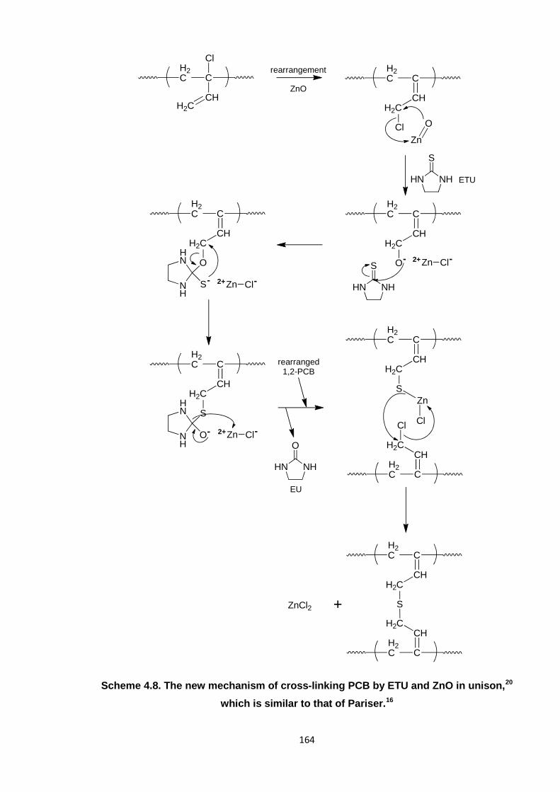
164
Scheme 4.8. The new mechanism of cross-linking PCB by ETU and ZnO in unison,20
which is similar to that of Pariser.16
H2C C
CHH2C
Cl
H2C C
CHH2C
O
Zn
O
NHHN
S
NHHN
S
H2C C
CHH2C
O
NH
HN
S
H2C C
CHH2C
S
NH
HN
O
rearranged1,2-PCB
H2C C
CHH2C
Cl
H2C C
CHH2C
S
Zn
Cl
H2C C
CHH2C
S
H2C C
CHH2C
ZnCl2
H2C C
CHH2C
Clrearrangement
ZnO
ETU
NHHN
O
EU
Zn Cl- -2+
Zn Cl- -2+
Zn Cl-2+-
165
4.1.6. Towards a safer accelerator system for cross-linking poly(2-chloro-1,3-
butadiene)
This PhD project, and that of Berry,1 was supported by Robinson Brothers Ltd. (RBL), who
were funded by a European project entitled SafeRubber.21 Involving several companies and
academic institutions, the principal objective of SafeRubber was to identify and produce an
alternative PCB rubber cross-linker to the hazardous reagent ETU.22-25 Achieving this was
primarily undertaken through RBL and Aston collaborating to elucidate the current cross-
linking mechanism, which would then shed light on how an alternative molecule should
function. To complete this section on cross-linking, it is appropriate to now summarise how
the project has achieved this aim, on the whole.
As concluded in the previous section (4.1.5.2), the bis-alkylation mechanism of Kovacic6 and
a modified Pariser mechanism20 have been deemed to occur in the standard industrial
ETU/ZnO cross-linking system for PCB. In the latter, ZnO was deemed crucial in activating
the polymer chain towards cross-linking through sulfur and in facilitating prompt
rearrangement of the 1,2-isomer.
Interestingly, during these studies it was found that DBTU and model diamine compounds,
PIP and DAB, caused cross-linking, as did the thiuram-based accelerator, TbuT. PIP, DAB
and DBTU formed hydrochloride salts when ZnO was absent; in the presence of the metal
oxide, no such salts existed as the FTIR peaks originally pertaining to such, in the 1600 –
1500 cm-1 region, disappeared over time. The N−C=S functionality of TbuT was disrupted
during the reaction with PCB, with and without ZnO; a carbon-sulfur bond was believed to
form when ZnO was present. All of these combined data inspired the prospect that the
alternative cross-linker (to ETU) should comprise a diamine, which would function by
removing the chlorine atom of the polymer and thus activate the chain. Additionally, a sulfur-
based compound would provide the cross-link atom/s.
A collection of potential new accelerators (PNAs) was devised by the SafeRubber consortium
(RBL and the various European project partners) and are listed in Table 4.4. These
molecules each comprised a cross-linker (sulfur-containing) component and an amine-based
activator. The theory behind this concoction was that the diamine would separate from the
complex during curing (i.e. on heating), activate the polymer chain and then the sulfur-
compound would be able to react with the polymer chain in a similar manner to ETU, via
sulfur (see Scheme 4.8 in Section 4.1.5.2). It was the role of the University of
Milano-Bicocca, Italy, to screen these various molecules regarding their potential hazardous
properties using select computer-simulated models. Quantitative structure-property (QSPR)
and quantitative structure-activity relationship (QSAR) data correlated each structure with
specific processes, such as chemical reactivities, and concluded on their suitability to this
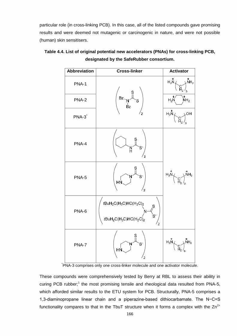
166
particular role (in cross-linking PCB). In this case, all of the listed compounds gave promising
results and were deemed not mutagenic or carcinogenic in nature, and were not possible
(human) skin sensitisers.
Table 4.4. List of original potential new accelerators (PNAs) for cross-linking PCB,
designated by the SafeRubber consortium.
Abbreviation Cross-linker Activator
PNA-1
PNA-2
PNA-3*
PNA-4
PNA-5
PNA-6
PNA-7
*PNA-3 comprises only one cross-linker molecule and one activator molecule.
These compounds were comprehensively tested by Berry at RBL to assess their ability in
curing PCB rubber;1 the most promising tensile and rheological data resulted from PNA-5,
which afforded similar results to the ETU system for PCB. Structurally, PNA-5 comprises a
1,3-diaminopropane linear chain and a piperazine-based dithiocarbamate. The N−C=S
functionality compares to that in the TbuT structure when it forms a complex with the Zn2+
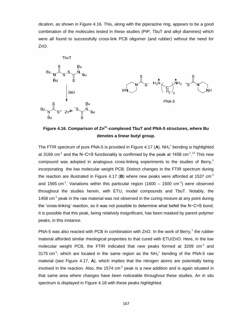
167
dication, as shown in Figure 4.16. This, along with the piperazine ring, appears to be a good
combination of the molecules tested in these studies (PIP, TbuT and alkyl diamines) which
were all found to successfully cross-link PCB oligomer (and rubber) without the need for
ZnO.
Figure 4.16. Comparison of Zn2+-complexed TbuT and PNA-5 structures, where Bu
denotes a linear butyl group.
The FTIR spectrum of pure PNA-5 is provided in Figure 4.17 (A). NH3+ bending is highlighted
at 3169 cm-1 and the N−C=S functionality is confirmed by the peak at 1458 cm-1.12 This new
compound was adopted in analogous cross-linking experiments to the studies of Berry,1
incorporating the low molecular weight PCB. Distinct changes in the FTIR spectrum during
the reaction are illustrated in Figure 4.17 (B) where new peaks were afforded at 1537 cm-1
and 1565 cm-1. Variations within this particular region (1600 – 1500 cm-1) were observed
throughout the studies herein, with ETU, model compounds and TbuT. Notably, the
1458 cm-1 peak in the raw material was not observed in the curing mixture at any point during
the ‘cross-linking’ reaction, so it was not possible to determine what befell the N−C=S bond.
It is possible that this peak, being relatively insignificant, has been masked by parent polymer
peaks, in this instance.
PNA-5 was also reacted with PCB in combination with ZnO. In the work of Berry,1 the rubber
material afforded similar rheological properties to that cured with ETU/ZnO. Here, in the low
molecular weight PCB, the FTIR indicated that new peaks formed at 3209 cm-1 and
3175 cm-1, which are located in the same region as the NH3+ bending of the PNA-5 raw
material (see Figure 4.17, A), which implies that the nitrogen atoms are potentially being
involved in the reaction. Also, the 1574 cm-1 peak is a new addition and is again situated in
that same area where changes have been noticeable throughout these studies. An in situ
spectrum is displayed in Figure 4.18 with these peaks highlighted.
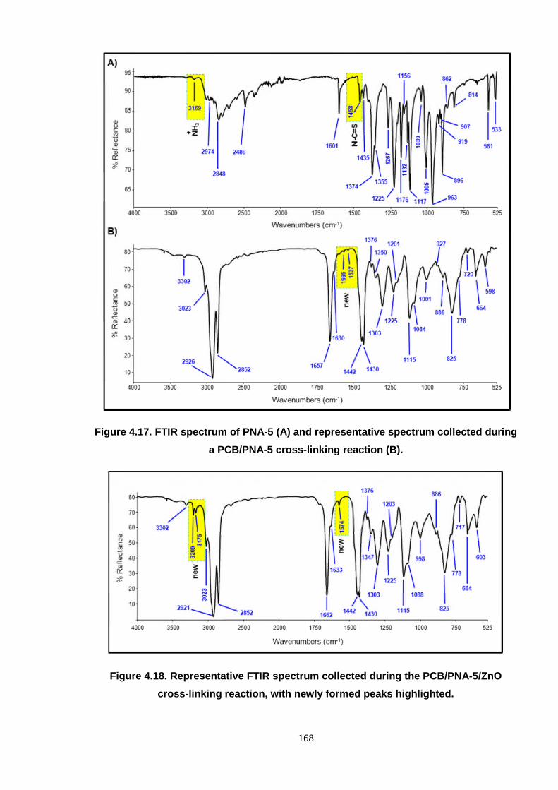
168
Figure 4.17. FTIR spectrum of PNA-5 (A) and representative spectrum collected during
a PCB/PNA-5 cross-linking reaction (B).
Figure 4.18. Representative FTIR spectrum collected during the PCB/PNA-5/ZnO
cross-linking reaction, with newly formed peaks highlighted.
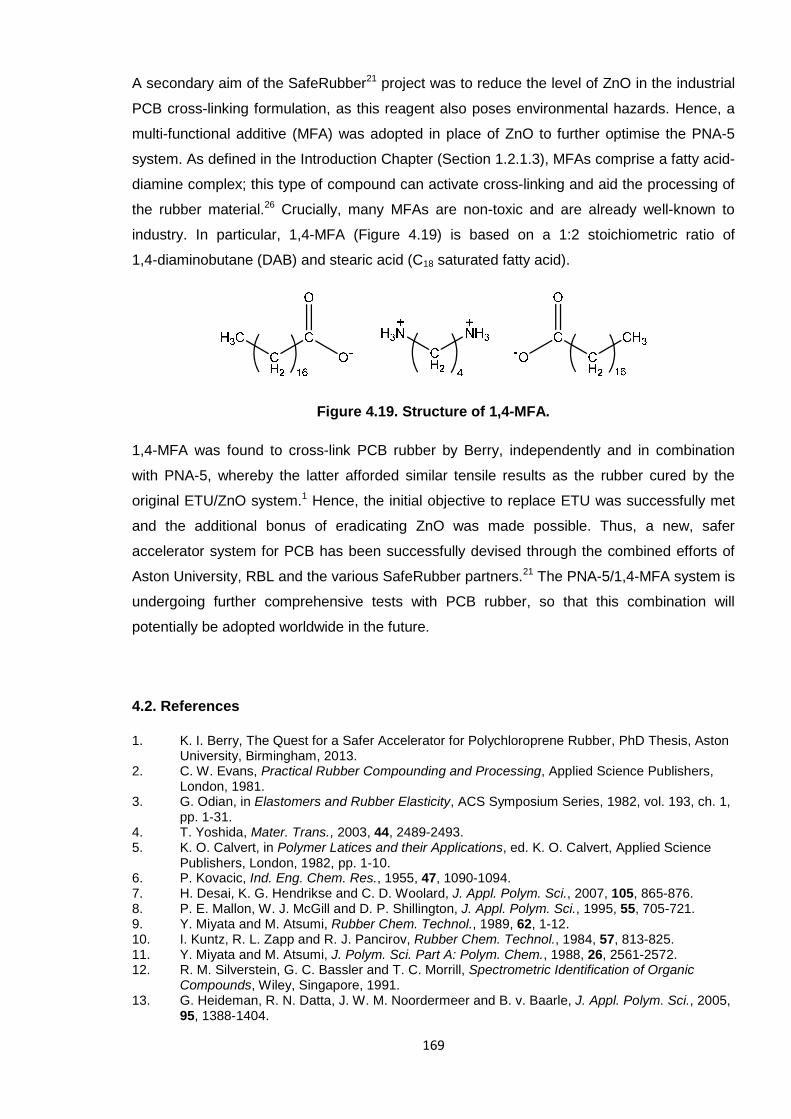
169
A secondary aim of the SafeRubber21 project was to reduce the level of ZnO in the industrial
PCB cross-linking formulation, as this reagent also poses environmental hazards. Hence, a
multi-functional additive (MFA) was adopted in place of ZnO to further optimise the PNA-5
system. As defined in the Introduction Chapter (Section 1.2.1.3), MFAs comprise a fatty acid-
diamine complex; this type of compound can activate cross-linking and aid the processing of
the rubber material.26 Crucially, many MFAs are non-toxic and are already well-known to
industry. In particular, 1,4-MFA (Figure 4.19) is based on a 1:2 stoichiometric ratio of
1,4-diaminobutane (DAB) and stearic acid (C18 saturated fatty acid).
Figure 4.19. Structure of 1,4-MFA.
1,4-MFA was found to cross-link PCB rubber by Berry, independently and in combination
with PNA-5, whereby the latter afforded similar tensile results as the rubber cured by the
original ETU/ZnO system.1 Hence, the initial objective to replace ETU was successfully met
and the additional bonus of eradicating ZnO was made possible. Thus, a new, safer
accelerator system for PCB has been successfully devised through the combined efforts of
Aston University, RBL and the various SafeRubber partners.21 The PNA-5/1,4-MFA system is
undergoing further comprehensive tests with PCB rubber, so that this combination will
potentially be adopted worldwide in the future.
4.2. References
1. K. I. Berry, The Quest for a Safer Accelerator for Polychloroprene Rubber, PhD Thesis, AstonUniversity, Birmingham, 2013.
2. C. W. Evans, Practical Rubber Compounding and Processing, Applied Science Publishers,London, 1981.
3. G. Odian, in Elastomers and Rubber Elasticity, ACS Symposium Series, 1982, vol. 193, ch. 1,pp. 1-31.
4. T. Yoshida, Mater. Trans., 2003, 44, 2489-2493.5. K. O. Calvert, in Polymer Latices and their Applications, ed. K. O. Calvert, Applied Science
Publishers, London, 1982, pp. 1-10.6. P. Kovacic, Ind. Eng. Chem. Res., 1955, 47, 1090-1094.7. H. Desai, K. G. Hendrikse and C. D. Woolard, J. Appl. Polym. Sci., 2007, 105, 865-876.8. P. E. Mallon, W. J. McGill and D. P. Shillington, J. Appl. Polym. Sci., 1995, 55, 705-721.9. Y. Miyata and M. Atsumi, Rubber Chem. Technol., 1989, 62, 1-12.10. I. Kuntz, R. L. Zapp and R. J. Pancirov, Rubber Chem. Technol., 1984, 57, 813-825.11. Y. Miyata and M. Atsumi, J. Polym. Sci. Part A: Polym. Chem., 1988, 26, 2561-2572.12. R. M. Silverstein, G. C. Bassler and T. C. Morrill, Spectrometric Identification of Organic
Compounds, Wiley, Singapore, 1991.13. G. Heideman, R. N. Datta, J. W. M. Noordermeer and B. v. Baarle, J. Appl. Polym. Sci., 2005,
95, 1388-1404.
170
14. A. S. Aprem, K. Joseph and S. Thomas, Rubber Chem. Technol., 2005, 78, 458-488.15. R. Vukov, Rubber Chem. Technol., 1984, 57, 284-290.16. R. Pariser, Kunststoffe, 1960, 50, 623-627.17. L. Krause and M. A. Whitehead, Mol. Phys., 1973, 25, 99-111.18. D. D. Perrin, Aust. J. Chem., 1964, 17, 484-488.19. L. Zhou, X. Liu, S. Kang, F. Zhang and C. Pan, Food Chemistry, 2013, 138, 1355-1359.20. K. I. Berry, M. Liu, K. Chakraborty, N. Pullan, A. West, C. Sammon and P. D. Topham, Rubber
Chem. Technol., 2014, Accepted.21. SafeRubber, http://www.saferubber.eu/, Accessed 11/03/2014.22. D. M. Smith, Occup. Med., 1976, 26, 92-94.23. D. M. Smith, Br. J. Ind. Med., 1984, 41, 362-366.24. R. S. Chhabra, S. Eustis, J. K. Haseman, P. J. Kurtz and B. D. Carlton, Fundam. Appl.
Toxicol., 1992, 18, 405-417.25. J. Ashby, Mutagenesis, 1986, 1, 3-16.26. G. Heideman, J. W. M. Noordermeer and R. N. Datta, Rubber Chem. Technol., 2006, 79, 561-
588.
171
CHAPTER 5
POLY(2-CHLORO-1,3-BUTADIENE)
LATEX DEVELOPMENT
172
5. Poly(2-chloro-1,3-butadiene) latex development
The second industrial component of this PhD project concerned the development of poly(2-
chloro-1,3-butadiene) (PCB) latex films. It was the overall aim of Robinson Brothers Ltd.
(RBL) to eventually replace the standard thiourea/guanidine-based accelerator system in the
manufacture of PCB latex rubber with safer, non-toxic reagents. This is a similar concept to
that for the cross-linking studies performed on PCB oligomers and rubber (detailed
previously in Chapter 4), where ethylene thiourea (ETU) was the primary concern.
5.1. Introduction
PCB latex is a diverse material, being adopted in coatings, adhesives and automotive parts,
for example,1, 2 (as previously reviewed in Section 1.3.3.2). One of the most important
applications, however, is in the manufacture of latex gloves. Natural rubber (NR) has been
prominent in this field, historically, but the focus has shifted to other materials owing to the
fact that residual proteins within NR can leach out of the material and cause skin allergies
amongst users.3 PCB latex rubber has been deemed a suitable alternative material, as
harmful proteins are absent in the first place and so the material is safer overall; PCB gloves
are less likely to afford skin dermatitis or cause skin sensitivity.3
The safety of latex gloves is of paramount importance as such items are widely used in the
public services and scientific professions, ultimately acting as a protective barrier to the skin.2
Certain chemicals used in the production of latex rubber are the primary offenders in terms of
causing skin problems amongst glove wearers; it is not the latex rubber itself which causes
direct harm to the skin.4 A review by Rose et al. highlights accelerator compounds as
generally the most harmful type of additives within a latex formulation,5 whereby the (human)
patch test studies of Geier et al. have revealed that thiuram derivatives most regularly cause
problems.6
Table 5.1 illustrates the main reagents employed throughout these latex studies, which were
incorporated as aqueous dispersions. As detailed in Section 1.3.3.1, accelerators are
responsible for linking polymer chains and creating the cross-linked network. Fillers are
responsible for providing abrasive resistance in the final material and surfactants are wholly
involved in stabilising the system. Antioxidants are present to aid in preventing degradation
of the final rubber material, such as by UV, heat, etc.2 To note, this part of the project utilised
commercially available, pre-prepared PCB in the form of an emulsion; it was not necessary
to synthesise polymer for these studies.
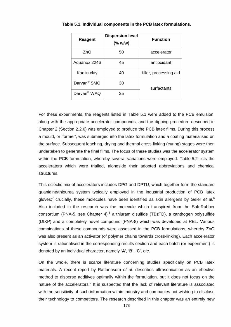
173
Table 5.1. Individual components in the PCB latex formulations.
ReagentDispersion level
(% w/w)Function
ZnO 50 accelerator
Aquanox 2246 45 antioxidant
Kaolin clay 40 filler, processing aid
Darvan® SMO 30surfactants
Darvan® WAQ 25
For these experiments, the reagents listed in Table 5.1 were added to the PCB emulsion,
along with the appropriate accelerator compounds, and the dipping procedure described in
Chapter 2 (Section 2.2.6) was employed to produce the PCB latex films. During this process
a mould, or ‘former’, was submerged into the latex formulation and a coating materialised on
the surface. Subsequent leaching, drying and thermal cross-linking (curing) stages were then
undertaken to generate the final films. The focus of these studies was the accelerator system
within the PCB formulation, whereby several variations were employed. Table 5.2 lists the
accelerators which were trialled, alongside their adopted abbreviations and chemical
structures.
This eclectic mix of accelerators includes DPG and DPTU, which together form the standard
guanidine/thiourea system typically employed in the industrial production of PCB latex
gloves;7 crucially, these molecules have been identified as skin allergens by Geier et al.6
Also included in the research was the molecule which transpired from the SafeRubber
consortium (PNA-5, see Chapter 4),8 a thiuram disulfide (TBzTD), a xanthogen polysulfide
(DIXP) and a completely novel compound (PNA-8) which was developed at RBL. Various
combinations of these compounds were assessed in the PCB formulations, whereby ZnO
was also present as an activator (of polymer chains towards cross-linking). Each accelerator
system is rationalised in the corresponding results section and each batch (or experiment) is
denoted by an individual character, namely ‘A’, ‘B’, ‘C’, etc.
On the whole, there is scarce literature concerning studies specifically on PCB latex
materials. A recent report by Rattanasom et al. describes ultrasonication as an effective
method to disperse additives optimally within the formulation, but it does not focus on the
nature of the accelerators.9 It is suspected that the lack of relevant literature is associated
with the sensitivity of such information within industry and companies not wishing to disclose
their technology to competitors. The research described in this chapter was an entirely new
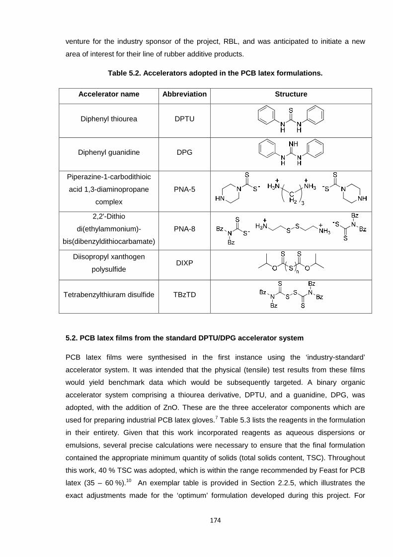
174
venture for the industry sponsor of the project, RBL, and was anticipated to initiate a new
area of interest for their line of rubber additive products.
Table 5.2. Accelerators adopted in the PCB latex formulations.
Accelerator name Abbreviation Structure
Diphenyl thiourea DPTU
Diphenyl guanidine DPG
Piperazine-1-carbodithioic
acid 1,3-diaminopropane
complex
PNA-5
2,2'-Dithio
di(ethylammonium)-
bis(dibenzyldithiocarbamate)
PNA-8
Diisopropyl xanthogen
polysulfideDIXP
Tetrabenzylthiuram disulfide TBzTD
5.2. PCB latex films from the standard DPTU/DPG accelerator system
PCB latex films were synthesised in the first instance using the ‘industry-standard’
accelerator system. It was intended that the physical (tensile) test results from these films
would yield benchmark data which would be subsequently targeted. A binary organic
accelerator system comprising a thiourea derivative, DPTU, and a guanidine, DPG, was
adopted, with the addition of ZnO. These are the three accelerator components which are
used for preparing industrial PCB latex gloves.7 Table 5.3 lists the reagents in the formulation
in their entirety. Given that this work incorporated reagents as aqueous dispersions or
emulsions, several precise calculations were necessary to ensure that the final formulation
contained the appropriate minimum quantity of solids (total solids content, TSC). Throughout
this work, 40 % TSC was adopted, which is within the range recommended by Feast for PCB
latex (35 – 60 %).10 An exemplar table is provided in Section 2.2.5, which illustrates the
exact adjustments made for the ‘optimum’ formulation developed during this project. For
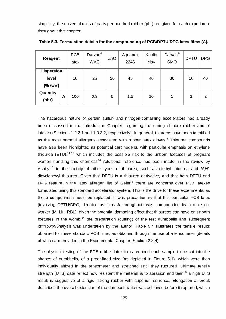
175
simplicity, the universal units of parts per hundred rubber (phr) are given for each experiment
throughout this chapter.
Table 5.3. Formulation details for the compounding of PCB/DPTU/DPG latex films (A).
ReagentPCB
latex
Darvan®
WAQZnO
Aquanox
2246
Kaolin
clay
Darvan®
SMODPTU DPG
Dispersion
level
(% w/w)
50 25 50 45 40 30 50 40
Quantity
(phr)A 100 0.3 5 1.5 10 1 2 2
The hazardous nature of certain sulfur- and nitrogen-containing accelerators has already
been discussed in the Introduction Chapter, regarding the curing of pure rubber and of
latexes (Sections 1.2.2.1 and 1.3.3.2, respectively). In general, thiurams have been identified
as the most harmful allergens associated with rubber latex gloves.6 Thiourea compounds
have also been highlighted as potential carcinogens, with particular emphasis on ethylene
thiourea (ETU),11-13 which includes the possible risk to the unborn foetuses of pregnant
women handling this chemical.14 Additional reference has been made, in the review by
Ashby,15 to the toxicity of other types of thiourea, such as diethyl thiourea and N,N'-
dicyclohexyl thiourea. Given that DPTU is a thiourea derivative, and that both DPTU and
DPG feature in the latex allergen list of Geier,6 there are concerns over PCB latexes
formulated using this standard accelerator system. This is the drive for these experiments, as
these compounds should be replaced. It was precautionary that this particular PCB latex
(involving DPTU/DPG, denoted as films A throughout) was compounded by a male co-
worker (M. Liu, RBL), given the potential damaging effect that thioureas can have on unborn
foetuses in the womb;14 the preparation (cutting) of the test dumbbells and subsequent
id="rpwp55nalysis was undertaken by the author. Table 5.4 illustrates the tensile results
obtained for these standard PCB films, as obtained through the use of a tensometer (details
of which are provided in the Experimental Chapter, Section 2.3.4).
The physical testing of the PCB rubber latex films required each sample to be cut into the
shapes of dumbbells, of a predefined size (as depicted in Figure 5.1), which were then
individually affixed in the tensometer and stretched until they ruptured. Ultimate tensile
strength (UTS) data reflect how resistant the material is to abrasion and tear;16 a high UTS
result is suggestive of a rigid, strong rubber with superior resilience. Elongation at break
describes the overall extension of the dumbbell which was achieved before it ruptured, which
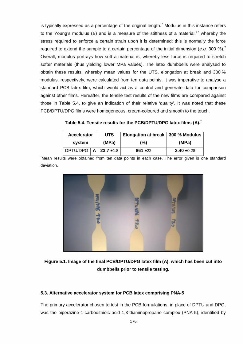
176
is typically expressed as a percentage of the original length.7 Modulus in this instance refers
to the Young’s modulus (E) and is a measure of the stiffness of a material,17 whereby the
stress required to enforce a certain strain upon it is determined; this is normally the force
required to extend the sample to a certain percentage of the initial dimension (e.g. 300 %).7
Overall, modulus portrays how soft a material is, whereby less force is required to stretch
softer materials (thus yielding lower MPa values). The latex dumbbells were analysed to
obtain these results, whereby mean values for the UTS, elongation at break and 300 %
modulus, respectively, were calculated from ten data points. It was imperative to analyse a
standard PCB latex film, which would act as a control and generate data for comparison
against other films. Hereafter, the tensile test results of the new films are compared against
those in Table 5.4, to give an indication of their relative ‘quality’. It was noted that these
PCB/DPTU/DPG films were homogeneous, cream-coloured and smooth to the touch.
Table 5.4. Tensile results for the PCB/DPTU/DPG latex films (A).*
Accelerator
system
UTS
(MPa)
Elongation at break
(%)
300 % Modulus
(MPa)
DPTU/DPG A 23.7 ±1.8 861 ±22 2.40 ±0.28
*Mean results were obtained from ten data points in each case. The error given is one standard
deviation.
Figure 5.1. Image of the final PCB/DPTU/DPG latex film (A), which has been cut into
dumbbells prior to tensile testing.
5.3. Alternative accelerator system for PCB latex comprising PNA-5
The primary accelerator chosen to test in the PCB formulations, in place of DPTU and DPG,
was the piperazine-1-carbodithioic acid 1,3-diaminopropane complex (PNA-5), identified by
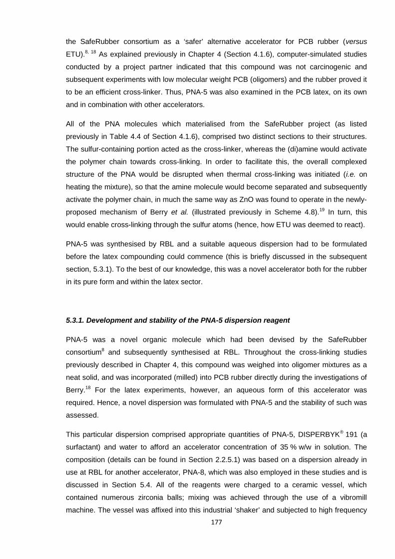
177
the SafeRubber consortium as a ‘safer’ alternative accelerator for PCB rubber (versus
ETU).8, 18 As explained previously in Chapter 4 (Section 4.1.6), computer-simulated studies
conducted by a project partner indicated that this compound was not carcinogenic and
subsequent experiments with low molecular weight PCB (oligomers) and the rubber proved it
to be an efficient cross-linker. Thus, PNA-5 was also examined in the PCB latex, on its own
and in combination with other accelerators.
All of the PNA molecules which materialised from the SafeRubber project (as listed
previously in Table 4.4 of Section 4.1.6), comprised two distinct sections to their structures.
The sulfur-containing portion acted as the cross-linker, whereas the (di)amine would activate
the polymer chain towards cross-linking. In order to facilitate this, the overall complexed
structure of the PNA would be disrupted when thermal cross-linking was initiated (i.e. on
heating the mixture), so that the amine molecule would become separated and subsequently
activate the polymer chain, in much the same way as ZnO was found to operate in the newly-
proposed mechanism of Berry et al. (illustrated previously in Scheme 4.8).19 In turn, this
would enable cross-linking through the sulfur atoms (hence, how ETU was deemed to react).
PNA-5 was synthesised by RBL and a suitable aqueous dispersion had to be formulated
before the latex compounding could commence (this is briefly discussed in the subsequent
section, 5.3.1). To the best of our knowledge, this was a novel accelerator both for the rubber
in its pure form and within the latex sector.
5.3.1. Development and stability of the PNA-5 dispersion reagent
PNA-5 was a novel organic molecule which had been devised by the SafeRubber
consortium8 and subsequently synthesised at RBL. Throughout the cross-linking studies
previously described in Chapter 4, this compound was weighed into oligomer mixtures as a
neat solid, and was incorporated (milled) into PCB rubber directly during the investigations of
Berry.18 For the latex experiments, however, an aqueous form of this accelerator was
required. Hence, a novel dispersion was formulated with PNA-5 and the stability of such was
assessed.
This particular dispersion comprised appropriate quantities of PNA-5, DISPERBYK® 191 (a
surfactant) and water to afford an accelerator concentration of 35 % w/w in solution. The
composition (details can be found in Section 2.2.5.1) was based on a dispersion already in
use at RBL for another accelerator, PNA-8, which was also employed in these studies and is
discussed in Section 5.4. All of the reagents were charged to a ceramic vessel, which
contained numerous zirconia balls; mixing was achieved through the use of a vibromill
machine. The vessel was affixed into this industrial ‘shaker’ and subjected to high frequency
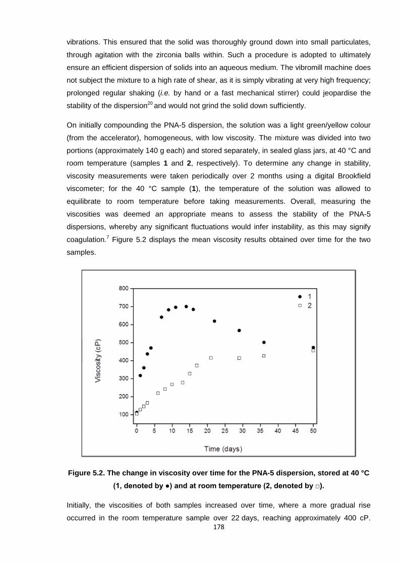
178
vibrations. This ensured that the solid was thoroughly ground down into small particulates,
through agitation with the zirconia balls within. Such a procedure is adopted to ultimately
ensure an efficient dispersion of solids into an aqueous medium. The vibromill machine does
not subject the mixture to a high rate of shear, as it is simply vibrating at very high frequency;
prolonged regular shaking (i.e. by hand or a fast mechanical stirrer) could jeopardise the
stability of the dispersion20 and would not grind the solid down sufficiently.
On initially compounding the PNA-5 dispersion, the solution was a light green/yellow colour
(from the accelerator), homogeneous, with low viscosity. The mixture was divided into two
portions (approximately 140 g each) and stored separately, in sealed glass jars, at 40 °C and
room temperature (samples 1 and 2, respectively). To determine any change in stability,
viscosity measurements were taken periodically over 2 months using a digital Brookfield
viscometer; for the 40 °C sample (1), the temperature of the solution was allowed to
equilibrate to room temperature before taking measurements. Overall, measuring the
viscosities was deemed an appropriate means to assess the stability of the PNA-5
dispersions, whereby any significant fluctuations would infer instability, as this may signify
coagulation.7 Figure 5.2 displays the mean viscosity results obtained over time for the two
samples.
Figure 5.2. The change in viscosity over time for the PNA-5 dispersion, stored at 40 °C
(1, denoted by ●) and at room temperature (2, denoted by □).
Initially, the viscosities of both samples increased over time, where a more gradual rise
occurred in the room temperature sample over 22 days, reaching approximately 400 cP.
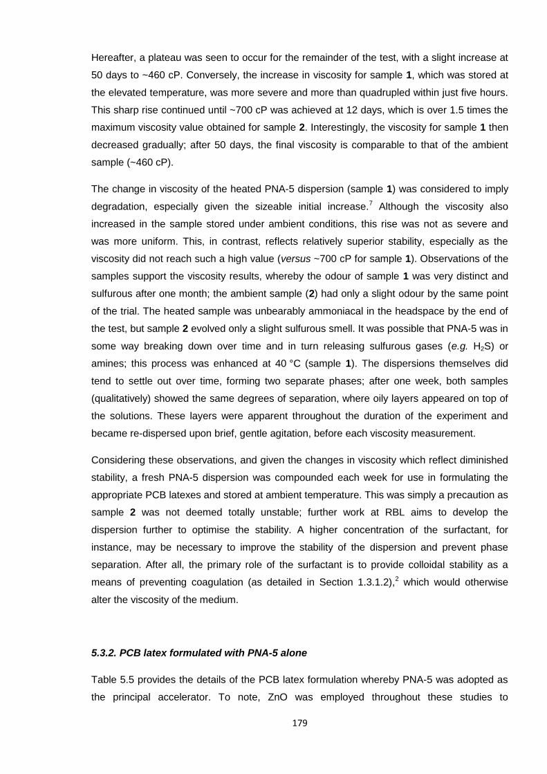
179
Hereafter, a plateau was seen to occur for the remainder of the test, with a slight increase at
50 days to ~460 cP. Conversely, the increase in viscosity for sample 1, which was stored at
the elevated temperature, was more severe and more than quadrupled within just five hours.
This sharp rise continued until ~700 cP was achieved at 12 days, which is over 1.5 times the
maximum viscosity value obtained for sample 2. Interestingly, the viscosity for sample 1 then
decreased gradually; after 50 days, the final viscosity is comparable to that of the ambient
sample (~460 cP).
The change in viscosity of the heated PNA-5 dispersion (sample 1) was considered to imply
degradation, especially given the sizeable initial increase.7 Although the viscosity also
increased in the sample stored under ambient conditions, this rise was not as severe and
was more uniform. This, in contrast, reflects relatively superior stability, especially as the
viscosity did not reach such a high value (versus ~700 cP for sample 1). Observations of the
samples support the viscosity results, whereby the odour of sample 1 was very distinct and
sulfurous after one month; the ambient sample (2) had only a slight odour by the same point
of the trial. The heated sample was unbearably ammoniacal in the headspace by the end of
the test, but sample 2 evolved only a slight sulfurous smell. It was possible that PNA-5 was in
some way breaking down over time and in turn releasing sulfurous gases (e.g. H2S) or
amines; this process was enhanced at 40 °C (sample 1). The dispersions themselves did
tend to settle out over time, forming two separate phases; after one week, both samples
(qualitatively) showed the same degrees of separation, where oily layers appeared on top of
the solutions. These layers were apparent throughout the duration of the experiment and
became re-dispersed upon brief, gentle agitation, before each viscosity measurement.
Considering these observations, and given the changes in viscosity which reflect diminished
stability, a fresh PNA-5 dispersion was compounded each week for use in formulating the
appropriate PCB latexes and stored at ambient temperature. This was simply a precaution as
sample 2 was not deemed totally unstable; further work at RBL aims to develop the
dispersion further to optimise the stability. A higher concentration of the surfactant, for
instance, may be necessary to improve the stability of the dispersion and prevent phase
separation. After all, the primary role of the surfactant is to provide colloidal stability as a
means of preventing coagulation (as detailed in Section 1.3.1.2),2 which would otherwise
alter the viscosity of the medium.
5.3.2. PCB latex formulated with PNA-5 alone
Table 5.5 provides the details of the PCB latex formulation whereby PNA-5 was adopted as
the principal accelerator. To note, ZnO was employed throughout these studies to
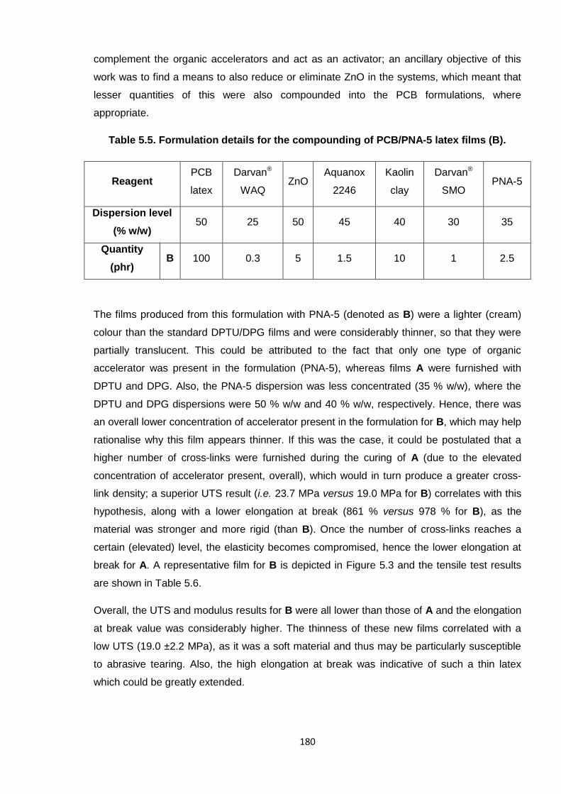
180
complement the organic accelerators and act as an activator; an ancillary objective of this
work was to find a means to also reduce or eliminate ZnO in the systems, which meant that
lesser quantities of this were also compounded into the PCB formulations, where
appropriate.
Table 5.5. Formulation details for the compounding of PCB/PNA-5 latex films (B).
ReagentPCB
latex
Darvan®
WAQZnO
Aquanox
2246
Kaolin
clay
Darvan®
SMOPNA-5
Dispersion level
(% w/w)50 25 50 45 40 30 35
Quantity
(phr)B 100 0.3 5 1.5 10 1 2.5
The films produced from this formulation with PNA-5 (denoted as B) were a lighter (cream)
colour than the standard DPTU/DPG films and were considerably thinner, so that they were
partially translucent. This could be attributed to the fact that only one type of organic
accelerator was present in the formulation (PNA-5), whereas films A were furnished with
DPTU and DPG. Also, the PNA-5 dispersion was less concentrated (35 % w/w), where the
DPTU and DPG dispersions were 50 % w/w and 40 % w/w, respectively. Hence, there was
an overall lower concentration of accelerator present in the formulation for B, which may help
rationalise why this film appears thinner. If this was the case, it could be postulated that a
higher number of cross-links were furnished during the curing of A (due to the elevated
concentration of accelerator present, overall), which would in turn produce a greater cross-
link density; a superior UTS result (i.e. 23.7 MPa versus 19.0 MPa for B) correlates with this
hypothesis, along with a lower elongation at break (861 % versus 978 % for B), as the
material was stronger and more rigid (than B). Once the number of cross-links reaches a
certain (elevated) level, the elasticity becomes compromised, hence the lower elongation at
break for A. A representative film for B is depicted in Figure 5.3 and the tensile test results
are shown in Table 5.6.
Overall, the UTS and modulus results for B were all lower than those of A and the elongation
at break value was considerably higher. The thinness of these new films correlated with a
low UTS (19.0 ±2.2 MPa), as it was a soft material and thus may be particularly susceptible
to abrasive tearing. Also, the high elongation at break was indicative of such a thin latex
which could be greatly extended.
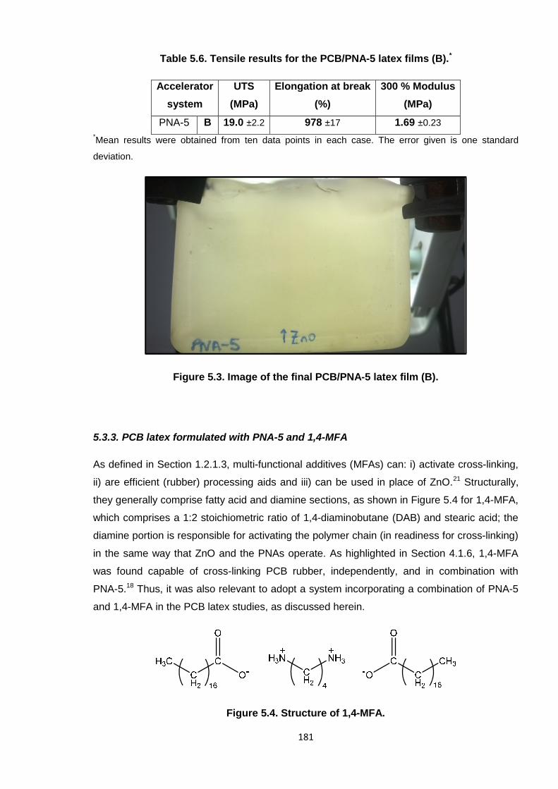
181
Table 5.6. Tensile results for the PCB/PNA-5 latex films (B).*
Accelerator
system
UTS
(MPa)
Elongation at break
(%)
300 % Modulus
(MPa)
PNA-5 B 19.0 ±2.2 978 ±17 1.69 ±0.23
*Mean results were obtained from ten data points in each case. The error given is one standard
deviation.
Figure 5.3. Image of the final PCB/PNA-5 latex film (B).
5.3.3. PCB latex formulated with PNA-5 and 1,4-MFA
As defined in Section 1.2.1.3, multi-functional additives (MFAs) can: i) activate cross-linking,
ii) are efficient (rubber) processing aids and iii) can be used in place of ZnO.21 Structurally,
they generally comprise fatty acid and diamine sections, as shown in Figure 5.4 for 1,4-MFA,
which comprises a 1:2 stoichiometric ratio of 1,4-diaminobutane (DAB) and stearic acid; the
diamine portion is responsible for activating the polymer chain (in readiness for cross-linking)
in the same way that ZnO and the PNAs operate. As highlighted in Section 4.1.6, 1,4-MFA
was found capable of cross-linking PCB rubber, independently, and in combination with
PNA-5.18 Thus, it was also relevant to adopt a system incorporating a combination of PNA-5
and 1,4-MFA in the PCB latex studies, as discussed herein.
Figure 5.4. Structure of 1,4-MFA.
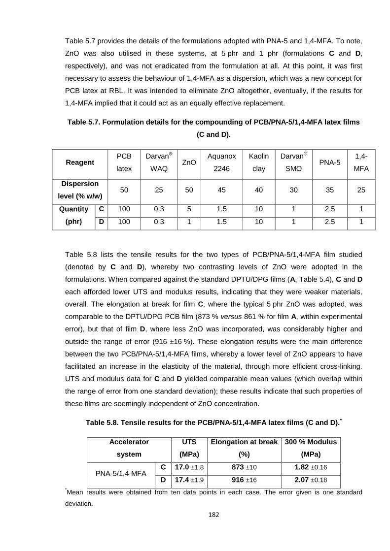
182
Table 5.7 provides the details of the formulations adopted with PNA-5 and 1,4-MFA. To note,
ZnO was also utilised in these systems, at 5 phr and 1 phr (formulations C and D,
respectively), and was not eradicated from the formulation at all. At this point, it was first
necessary to assess the behaviour of 1,4-MFA as a dispersion, which was a new concept for
PCB latex at RBL. It was intended to eliminate ZnO altogether, eventually, if the results for
1,4-MFA implied that it could act as an equally effective replacement.
Table 5.7. Formulation details for the compounding of PCB/PNA-5/1,4-MFA latex films
(C and D).
ReagentPCB
latex
Darvan®
WAQZnO
Aquanox
2246
Kaolin
clay
Darvan®
SMOPNA-5
1,4-
MFA
Dispersion
level (% w/w)50 25 50 45 40 30 35 25
Quantity
(phr)
C 100 0.3 5 1.5 10 1 2.5 1
D 100 0.3 1 1.5 10 1 2.5 1
Table 5.8 lists the tensile results for the two types of PCB/PNA-5/1,4-MFA film studied
(denoted by C and D), whereby two contrasting levels of ZnO were adopted in the
formulations. When compared against the standard DPTU/DPG films (A, Table 5.4), C and D
each afforded lower UTS and modulus results, indicating that they were weaker materials,
overall. The elongation at break for film C, where the typical 5 phr ZnO was adopted, was
comparable to the DPTU/DPG PCB film (873 % versus 861 % for film A, within experimental
error), but that of film D, where less ZnO was incorporated, was considerably higher and
outside the range of error (916 ±16 %). These elongation results were the main difference
between the two PCB/PNA-5/1,4-MFA films, whereby a lower level of ZnO appears to have
facilitated an increase in the elasticity of the material, through more efficient cross-linking.
UTS and modulus data for C and D yielded comparable mean values (which overlap within
the range of error from one standard deviation); these results indicate that such properties of
these films are seemingly independent of ZnO concentration.
Table 5.8. Tensile results for the PCB/PNA-5/1,4-MFA latex films (C and D).*
Accelerator
system
UTS
(MPa)
Elongation at break
(%)
300 % Modulus
(MPa)
PNA-5/1,4-MFAC 17.0 ±1.8 873 ±10 1.82 ±0.16
D 17.4 ±1.9 916 ±16 2.07 ±0.18
*Mean results were obtained from ten data points in each case. The error given is one standard
deviation.
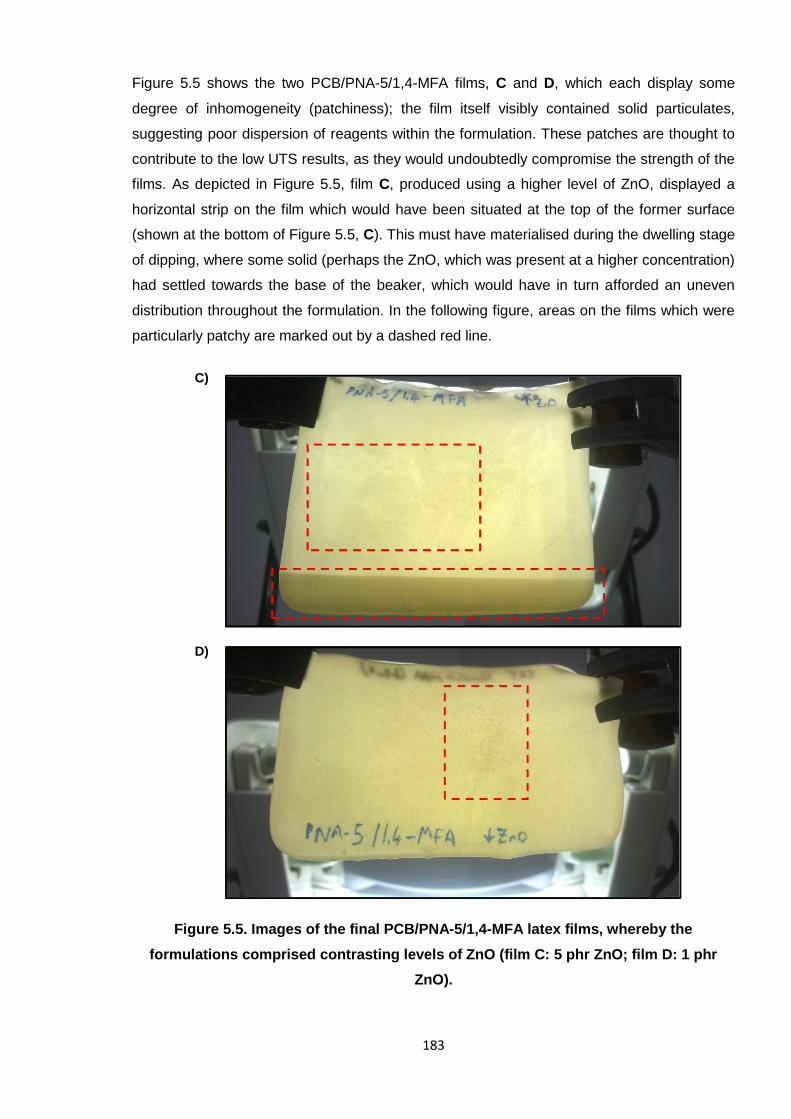
183
Figure 5.5 shows the two PCB/PNA-5/1,4-MFA films, C and D, which each display some
degree of inhomogeneity (patchiness); the film itself visibly contained solid particulates,
suggesting poor dispersion of reagents within the formulation. These patches are thought to
contribute to the low UTS results, as they would undoubtedly compromise the strength of the
films. As depicted in Figure 5.5, film C, produced using a higher level of ZnO, displayed a
horizontal strip on the film which would have been situated at the top of the former surface
(shown at the bottom of Figure 5.5, C). This must have materialised during the dwelling stage
of dipping, where some solid (perhaps the ZnO, which was present at a higher concentration)
had settled towards the base of the beaker, which would have in turn afforded an uneven
distribution throughout the formulation. In the following figure, areas on the films which were
particularly patchy are marked out by a dashed red line.
Figure 5.5. Images of the final PCB/PNA-5/1,4-MFA latex films, whereby the
formulations comprised contrasting levels of ZnO (film C: 5 phr ZnO; film D: 1 phr
ZnO).
C)
D)
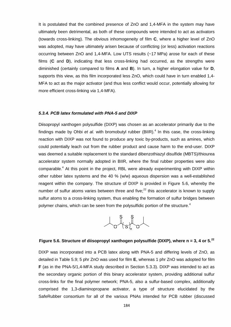
184
It is postulated that the combined presence of ZnO and 1,4-MFA in the system may have
ultimately been detrimental, as both of these compounds were intended to act as activators
(towards cross-linking). The obvious inhomogeneity of film C, where a higher level of ZnO
was adopted, may have ultimately arisen because of conflicting (or less) activation reactions
occurring between ZnO and 1,4-MFA. Low UTS results (~17 MPa) arose for each of these
films (C and D), indicating that less cross-linking had occurred, as the strengths were
diminished (certainly compared to films A and B). In turn, a higher elongation value for D,
supports this view, as this film incorporated less ZnO, which could have in turn enabled 1,4-
MFA to act as the major activator (and thus less conflict would occur, potentially allowing for
more efficient cross-linking via 1,4-MFA).
5.3.4. PCB latex formulated with PNA-5 and DIXP
Diisopropyl xanthogen polysulfide (DIXP) was chosen as an accelerator primarily due to the
findings made by Ohbi et al. with bromobutyl rubber (BIIR).4 In this case, the cross-linking
reaction with DIXP was not found to produce any toxic by-products, such as amines, which
could potentially leach out from the rubber product and cause harm to the end-user. DIXP
was deemed a suitable replacement to the standard dibenzothiazyl disulfide (MBTS)/thiourea
accelerator system normally adopted in BIIR, where the final rubber properties were also
comparable.4 At this point in the project, RBL were already experimenting with DIXP within
other rubber latex systems and the 40 % (w/w) aqueous dispersion was a well-established
reagent within the company. The structure of DIXP is provided in Figure 5.6, whereby the
number of sulfur atoms varies between three and five;22 this accelerator is known to supply
sulfur atoms to a cross-linking system, thus enabling the formation of sulfur bridges between
polymer chains, which can be seen from the polysulfidic portion of the structure.4
Figure 5.6. Structure of diisopropyl xanthogen polysulfide (DIXP), where n = 3, 4 or 5.22
DIXP was incorporated into a PCB latex along with PNA-5 and differing levels of ZnO, as
detailed in Table 5.9; 5 phr ZnO was used for film E, whereas 1 phr ZnO was adopted for film
F (as in the PNA-5/1,4-MFA study described in Section 5.3.3). DIXP was intended to act as
the secondary organic portion of this binary accelerator system, providing additional sulfur
cross-links for the final polymer network; PNA-5, also a sulfur-based complex, additionally
comprised the 1,3-diaminopropane activator, a type of structure elucidated by the
SafeRubber consortium for all of the various PNAs intended for PCB rubber (discussed
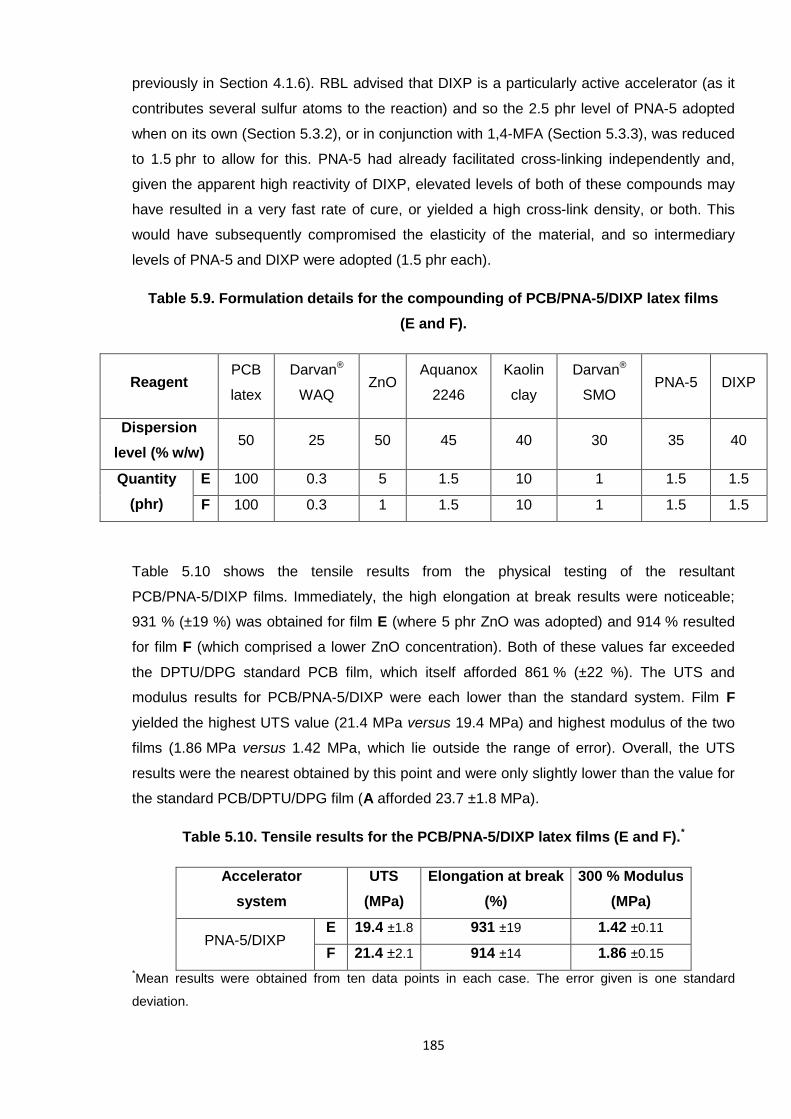
185
previously in Section 4.1.6). RBL advised that DIXP is a particularly active accelerator (as it
contributes several sulfur atoms to the reaction) and so the 2.5 phr level of PNA-5 adopted
when on its own (Section 5.3.2), or in conjunction with 1,4-MFA (Section 5.3.3), was reduced
to 1.5 phr to allow for this. PNA-5 had already facilitated cross-linking independently and,
given the apparent high reactivity of DIXP, elevated levels of both of these compounds may
have resulted in a very fast rate of cure, or yielded a high cross-link density, or both. This
would have subsequently compromised the elasticity of the material, and so intermediary
levels of PNA-5 and DIXP were adopted (1.5 phr each).
Table 5.9. Formulation details for the compounding of PCB/PNA-5/DIXP latex films
(E and F).
ReagentPCB
latex
Darvan®
WAQZnO
Aquanox
2246
Kaolin
clay
Darvan®
SMOPNA-5 DIXP
Dispersion
level (% w/w)50 25 50 45 40 30 35 40
Quantity
(phr)
E 100 0.3 5 1.5 10 1 1.5 1.5
F 100 0.3 1 1.5 10 1 1.5 1.5
Table 5.10 shows the tensile results from the physical testing of the resultant
PCB/PNA-5/DIXP films. Immediately, the high elongation at break results were noticeable;
931 % (±19 %) was obtained for film E (where 5 phr ZnO was adopted) and 914 % resulted
for film F (which comprised a lower ZnO concentration). Both of these values far exceeded
the DPTU/DPG standard PCB film, which itself afforded 861 % (±22 %). The UTS and
modulus results for PCB/PNA-5/DIXP were each lower than the standard system. Film F
yielded the highest UTS value (21.4 MPa versus 19.4 MPa) and highest modulus of the two
films (1.86 MPa versus 1.42 MPa, which lie outside the range of error). Overall, the UTS
results were the nearest obtained by this point and were only slightly lower than the value for
the standard PCB/DPTU/DPG film (A afforded 23.7 ±1.8 MPa).
Table 5.10. Tensile results for the PCB/PNA-5/DIXP latex films (E and F).*
Accelerator
system
UTS
(MPa)
Elongation at break
(%)
300 % Modulus
(MPa)
PNA-5/DIXPE 19.4 ±1.8 931 ±19 1.42 ±0.11
F 21.4 ±2.1 914 ±14 1.86 ±0.15
*Mean results were obtained from ten data points in each case. The error given is one standard
deviation.
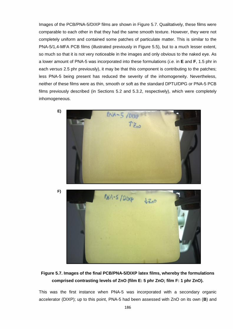
186
Images of the PCB/PNA-5/DIXP films are shown in Figure 5.7. Qualitatively, these films were
comparable to each other in that they had the same smooth texture. However, they were not
completely uniform and contained some patches of particulate matter. This is similar to the
PNA-5/1,4-MFA PCB films (illustrated previously in Figure 5.5), but to a much lesser extent,
so much so that it is not very noticeable in the images and only obvious to the naked eye. As
a lower amount of PNA-5 was incorporated into these formulations (i.e. in E and F, 1.5 phr in
each versus 2.5 phr previously), it may be that this component is contributing to the patches;
less PNA-5 being present has reduced the severity of the inhomogeneity. Nevertheless,
neither of these films were as thin, smooth or soft as the standard DPTU/DPG or PNA-5 PCB
films previously described (in Sections 5.2 and 5.3.2, respectively), which were completely
inhomogeneous.
Figure 5.7. Images of the final PCB/PNA-5/DIXP latex films, whereby the formulations
comprised contrasting levels of ZnO (film E: 5 phr ZnO; film F: 1 phr ZnO).
This was the first instance when PNA-5 was incorporated with a secondary organic
accelerator (DIXP); up to this point, PNA-5 had been assessed with ZnO on its own (B) and
E)
F)
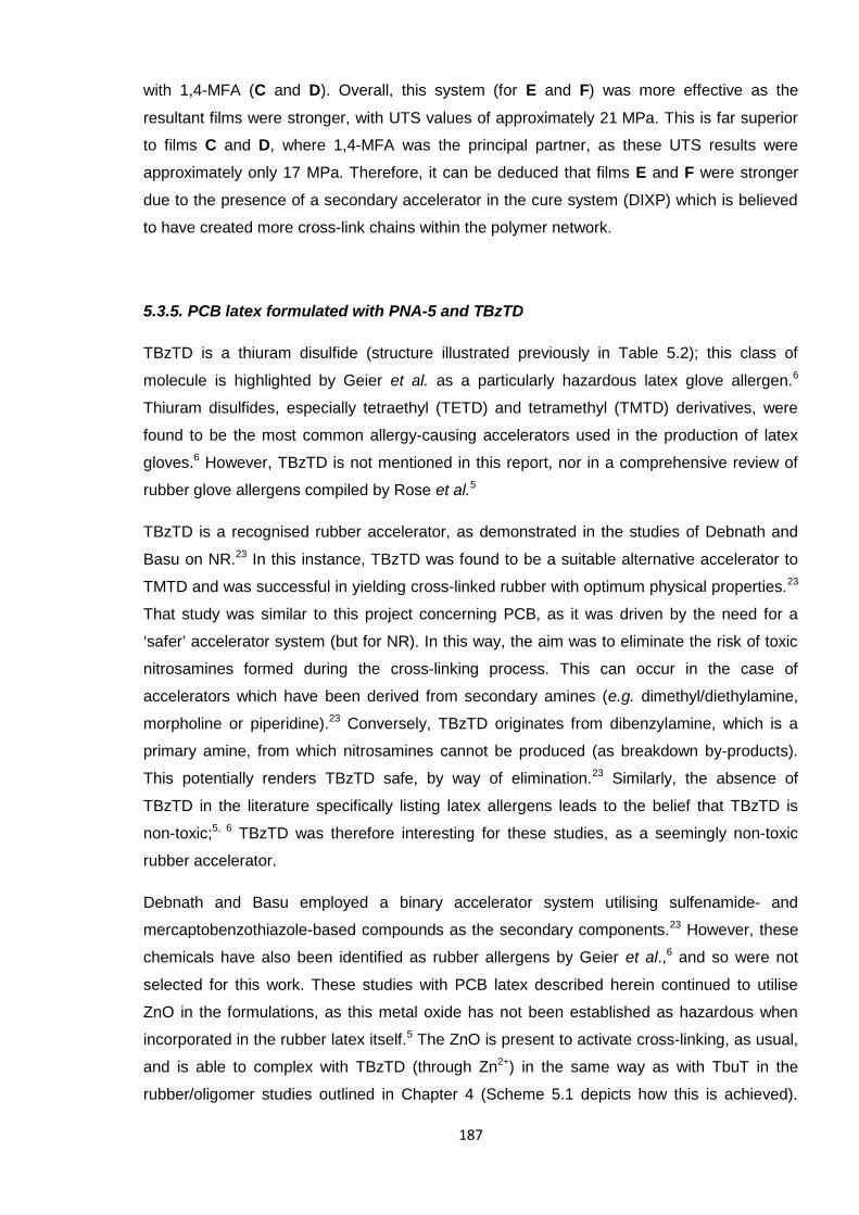
187
with 1,4-MFA (C and D). Overall, this system (for E and F) was more effective as the
resultant films were stronger, with UTS values of approximately 21 MPa. This is far superior
to films C and D, where 1,4-MFA was the principal partner, as these UTS results were
approximately only 17 MPa. Therefore, it can be deduced that films E and F were stronger
due to the presence of a secondary accelerator in the cure system (DIXP) which is believed
to have created more cross-link chains within the polymer network.
5.3.5. PCB latex formulated with PNA-5 and TBzTD
TBzTD is a thiuram disulfide (structure illustrated previously in Table 5.2); this class of
molecule is highlighted by Geier et al. as a particularly hazardous latex glove allergen.6
Thiuram disulfides, especially tetraethyl (TETD) and tetramethyl (TMTD) derivatives, were
found to be the most common allergy-causing accelerators used in the production of latex
gloves.6 However, TBzTD is not mentioned in this report, nor in a comprehensive review of
rubber glove allergens compiled by Rose et al.5
TBzTD is a recognised rubber accelerator, as demonstrated in the studies of Debnath and
Basu on NR.23 In this instance, TBzTD was found to be a suitable alternative accelerator to
TMTD and was successful in yielding cross-linked rubber with optimum physical properties.23
That study was similar to this project concerning PCB, as it was driven by the need for a
‘safer’ accelerator system (but for NR). In this way, the aim was to eliminate the risk of toxic
nitrosamines formed during the cross-linking process. This can occur in the case of
accelerators which have been derived from secondary amines (e.g. dimethyl/diethylamine,
morpholine or piperidine).23 Conversely, TBzTD originates from dibenzylamine, which is a
primary amine, from which nitrosamines cannot be produced (as breakdown by-products).
This potentially renders TBzTD safe, by way of elimination.23 Similarly, the absence of
TBzTD in the literature specifically listing latex allergens leads to the belief that TBzTD is
non-toxic;5, 6 TBzTD was therefore interesting for these studies, as a seemingly non-toxic
rubber accelerator.
Debnath and Basu employed a binary accelerator system utilising sulfenamide- and
mercaptobenzothiazole-based compounds as the secondary components.23 However, these
chemicals have also been identified as rubber allergens by Geier et al.,6 and so were not
selected for this work. These studies with PCB latex described herein continued to utilise
ZnO in the formulations, as this metal oxide has not been established as hazardous when
incorporated in the rubber latex itself.5 The ZnO is present to activate cross-linking, as usual,
and is able to complex with TBzTD (through Zn2+) in the same way as with TbuT in the
rubber/oligomer studies outlined in Chapter 4 (Scheme 5.1 depicts how this is achieved).
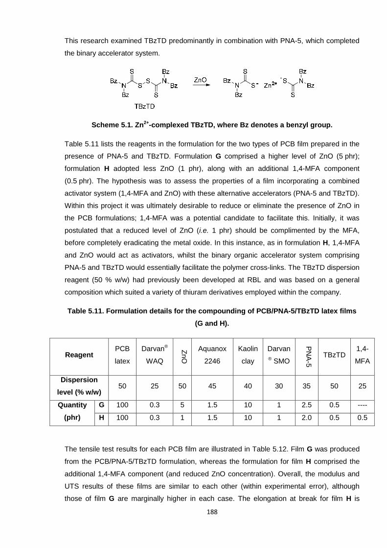
188
This research examined TBzTD predominantly in combination with PNA-5, which completed
the binary accelerator system.
Scheme 5.1. Zn2+-complexed TBzTD, where Bz denotes a benzyl group.
Table 5.11 lists the reagents in the formulation for the two types of PCB film prepared in the
presence of PNA-5 and TBzTD. Formulation G comprised a higher level of ZnO (5 phr);
formulation H adopted less ZnO (1 phr), along with an additional 1,4-MFA component
(0.5 phr). The hypothesis was to assess the properties of a film incorporating a combined
activator system (1,4-MFA and ZnO) with these alternative accelerators (PNA-5 and TBzTD).
Within this project it was ultimately desirable to reduce or eliminate the presence of ZnO in
the PCB formulations; 1,4-MFA was a potential candidate to facilitate this. Initially, it was
postulated that a reduced level of ZnO (i.e. 1 phr) should be complimented by the MFA,
before completely eradicating the metal oxide. In this instance, as in formulation H, 1,4-MFA
and ZnO would act as activators, whilst the binary organic accelerator system comprising
PNA-5 and TBzTD would essentially facilitate the polymer cross-links. The TBzTD dispersion
reagent (50 % w/w) had previously been developed at RBL and was based on a general
composition which suited a variety of thiuram derivatives employed within the company.
Table 5.11. Formulation details for the compounding of PCB/PNA-5/TBzTD latex films
(G and H).
ReagentPCB
latex
Darvan®
WAQ
ZnO
Aquanox
2246
Kaolin
clay
Darvan
® SMO
PN
A-5
TBzTD1,4-
MFA
Dispersion
level (% w/w)50 25 50 45 40 30 35 50 25
Quantity
(phr)
G 100 0.3 5 1.5 10 1 2.5 0.5 ----
H 100 0.3 1 1.5 10 1 2.0 0.5 0.5
The tensile test results for each PCB film are illustrated in Table 5.12. Film G was produced
from the PCB/PNA-5/TBzTD formulation, whereas the formulation for film H comprised the
additional 1,4-MFA component (and reduced ZnO concentration). Overall, the modulus and
UTS results of these films are similar to each other (within experimental error), although
those of film G are marginally higher in each case. The elongation at break for film H is
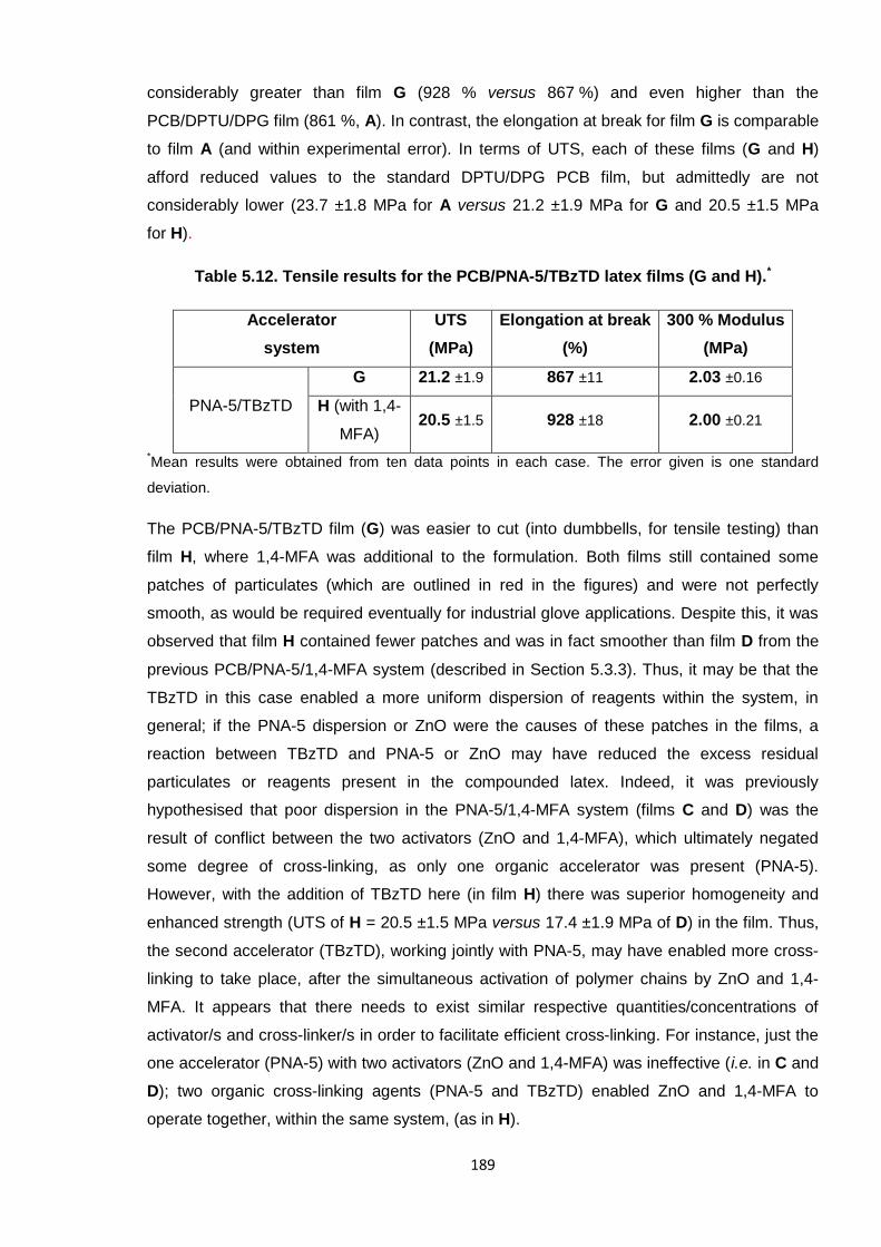
189
considerably greater than film G (928 % versus 867 %) and even higher than the
PCB/DPTU/DPG film (861 %, A). In contrast, the elongation at break for film G is comparable
to film A (and within experimental error). In terms of UTS, each of these films (G and H)
afford reduced values to the standard DPTU/DPG PCB film, but admittedly are not
considerably lower (23.7 ±1.8 MPa for A versus 21.2 ±1.9 MPa for G and 20.5 ±1.5 MPa
for H).
Table 5.12. Tensile results for the PCB/PNA-5/TBzTD latex films (G and H).*
Accelerator
system
UTS
(MPa)
Elongation at break
(%)
300 % Modulus
(MPa)
PNA-5/TBzTD
G 21.2 ±1.9 867 ±11 2.03 ±0.16
H (with 1,4-
MFA)20.5 ±1.5 928 ±18 2.00 ±0.21
*Mean results were obtained from ten data points in each case. The error given is one standard
deviation.
The PCB/PNA-5/TBzTD film (G) was easier to cut (into dumbbells, for tensile testing) than
film H, where 1,4-MFA was additional to the formulation. Both films still contained some
patches of particulates (which are outlined in red in the figures) and were not perfectly
smooth, as would be required eventually for industrial glove applications. Despite this, it was
observed that film H contained fewer patches and was in fact smoother than film D from the
previous PCB/PNA-5/1,4-MFA system (described in Section 5.3.3). Thus, it may be that the
TBzTD in this case enabled a more uniform dispersion of reagents within the system, in
general; if the PNA-5 dispersion or ZnO were the causes of these patches in the films, a
reaction between TBzTD and PNA-5 or ZnO may have reduced the excess residual
particulates or reagents present in the compounded latex. Indeed, it was previously
hypothesised that poor dispersion in the PNA-5/1,4-MFA system (films C and D) was the
result of conflict between the two activators (ZnO and 1,4-MFA), which ultimately negated
some degree of cross-linking, as only one organic accelerator was present (PNA-5).
However, with the addition of TBzTD here (in film H) there was superior homogeneity and
enhanced strength (UTS of H = 20.5 ±1.5 MPa versus 17.4 ±1.9 MPa of D) in the film. Thus,
the second accelerator (TBzTD), working jointly with PNA-5, may have enabled more cross-
linking to take place, after the simultaneous activation of polymer chains by ZnO and 1,4-
MFA. It appears that there needs to exist similar respective quantities/concentrations of
activator/s and cross-linker/s in order to facilitate efficient cross-linking. For instance, just the
one accelerator (PNA-5) with two activators (ZnO and 1,4-MFA) was ineffective (i.e. in C and
D); two organic cross-linking agents (PNA-5 and TBzTD) enabled ZnO and 1,4-MFA to
operate together, within the same system, (as in H).
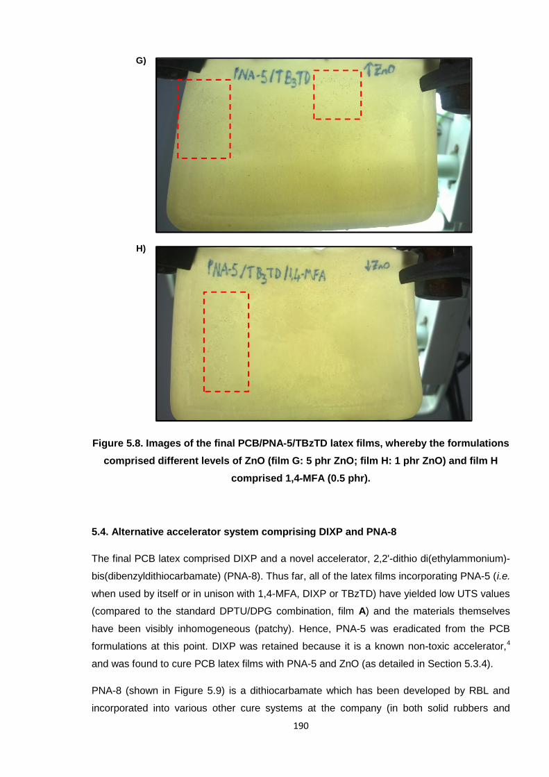
190
Figure 5.8. Images of the final PCB/PNA-5/TBzTD latex films, whereby the formulations
comprised different levels of ZnO (film G: 5 phr ZnO; film H: 1 phr ZnO) and film H
comprised 1,4-MFA (0.5 phr).
5.4. Alternative accelerator system comprising DIXP and PNA-8
The final PCB latex comprised DIXP and a novel accelerator, 2,2'-dithio di(ethylammonium)-
bis(dibenzyldithiocarbamate) (PNA-8). Thus far, all of the latex films incorporating PNA-5 (i.e.
when used by itself or in unison with 1,4-MFA, DIXP or TBzTD) have yielded low UTS values
(compared to the standard DPTU/DPG combination, film A) and the materials themselves
have been visibly inhomogeneous (patchy). Hence, PNA-5 was eradicated from the PCB
formulations at this point. DIXP was retained because it is a known non-toxic accelerator,4
and was found to cure PCB latex films with PNA-5 and ZnO (as detailed in Section 5.3.4).
PNA-8 (shown in Figure 5.9) is a dithiocarbamate which has been developed by RBL and
incorporated into various other cure systems at the company (in both solid rubbers and
G)
H)
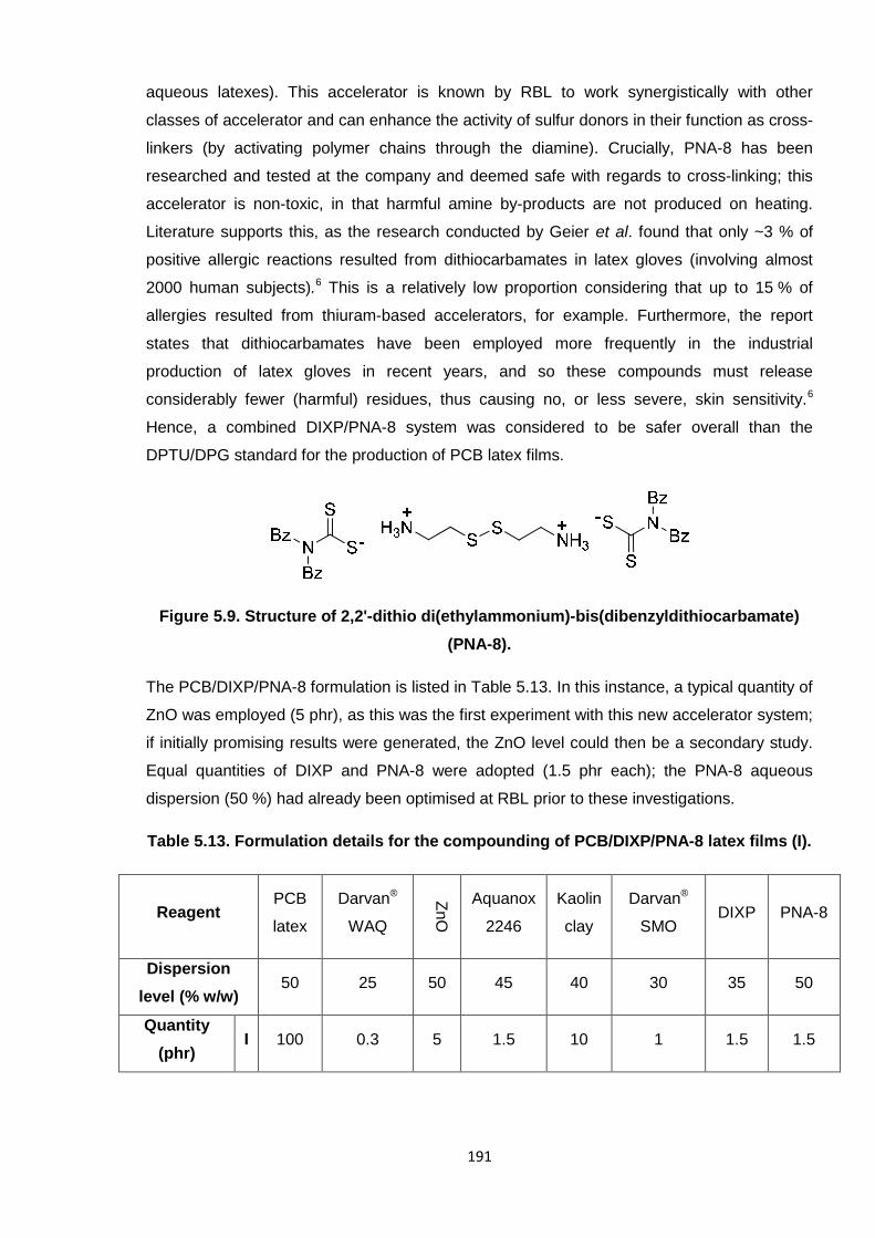
191
aqueous latexes). This accelerator is known by RBL to work synergistically with other
classes of accelerator and can enhance the activity of sulfur donors in their function as cross-
linkers (by activating polymer chains through the diamine). Crucially, PNA-8 has been
researched and tested at the company and deemed safe with regards to cross-linking; this
accelerator is non-toxic, in that harmful amine by-products are not produced on heating.
Literature supports this, as the research conducted by Geier et al. found that only ~3 % of
positive allergic reactions resulted from dithiocarbamates in latex gloves (involving almost
2000 human subjects).6 This is a relatively low proportion considering that up to 15 % of
allergies resulted from thiuram-based accelerators, for example. Furthermore, the report
states that dithiocarbamates have been employed more frequently in the industrial
production of latex gloves in recent years, and so these compounds must release
considerably fewer (harmful) residues, thus causing no, or less severe, skin sensitivity.6
Hence, a combined DIXP/PNA-8 system was considered to be safer overall than the
DPTU/DPG standard for the production of PCB latex films.
Figure 5.9. Structure of 2,2'-dithio di(ethylammonium)-bis(dibenzyldithiocarbamate)
(PNA-8).
The PCB/DIXP/PNA-8 formulation is listed in Table 5.13. In this instance, a typical quantity of
ZnO was employed (5 phr), as this was the first experiment with this new accelerator system;
if initially promising results were generated, the ZnO level could then be a secondary study.
Equal quantities of DIXP and PNA-8 were adopted (1.5 phr each); the PNA-8 aqueous
dispersion (50 %) had already been optimised at RBL prior to these investigations.
Table 5.13. Formulation details for the compounding of PCB/DIXP/PNA-8 latex films (I).
ReagentPCB
latex
Darvan®
WAQ
ZnO
Aquanox
2246
Kaolin
clay
Darvan®
SMODIXP PNA-8
Dispersion
level (% w/w)50 25 50 45 40 30 35 50
Quantity
(phr)I 100 0.3 5 1.5 10 1 1.5 1.5
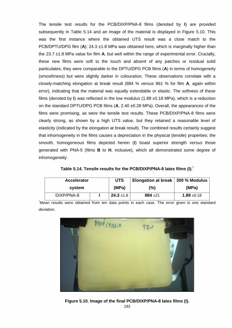
192
The tensile test results for the PCB/DIXP/PNA-8 films (denoted by I) are provided
subsequently in Table 5.14 and an image of the material is displayed in Figure 5.10. This
was the first instance where the obtained UTS result was a close match to the
PCB/DPTU/DPG film (A); 24.3 ±1.8 MPa was obtained here, which is marginally higher than
the 23.7 ±1.8 MPa value for film A, but well within the range of experimental error. Crucially,
these new films were soft to the touch and absent of any patches or residual solid
particulates; they were comparable to the DPTU/DPG PCB films (A) in terms of homogeneity
(smoothness) but were slightly darker in colouration. These observations correlate with a
closely-matching elongation at break result (884 % versus 861 % for film A, again within
error), indicating that the material was equally extendable or elastic. The softness of these
films (denoted by I) was reflected in the low modulus (1.89 ±0.18 MPa), which is a reduction
on the standard DPTU/DPG PCB films (A, 2.40 ±0.28 MPa). Overall, the appearances of the
films were promising, as were the tensile test results. These PCB/DIXP/PNA-8 films were
clearly strong, as shown by a high UTS value, but they retained a reasonable level of
elasticity (indicated by the elongation at break result). The combined results certainly suggest
that inhomogeneity in the films causes a depreciation in the physical (tensile) properties; the
smooth, homogeneous films depicted herein (I) boast superior strength versus those
generated with PNA-5 (films B to H, inclusive), which all demonstrated some degree of
inhomogeneity.
Table 5.14. Tensile results for the PCB/DIXP/PNA-8 latex films (I).*
Accelerator
system
UTS
(MPa)
Elongation at break
(%)
300 % Modulus
(MPa)
DIXP/PNA-8 I 24.3 ±1.8 884 ±21 1.89 ±0.18
*Mean results were obtained from ten data points in each case. The error given is one standard
deviation.
Figure 5.10. Image of the final PCB/DIXP/PNA-8 latex films (I).
193
The DIXP/PNA-8 system combined an organic accelerator component (DIXP) with the
bifunctional PNA-8 (which comprises a complex between a diamine and sulfur compound).
This is the same way in which the PNA-5/TBzTD system was intended to operate; the
performances of films I and G can therefore be directly compared, relative to the nature of
the different accelerators (i.e. PNA-5 versus PNA-8 and TBzTD versus DIXP). Overall, I
afforded a higher UTS (24.3 MPa versus 21.2 MPa of G) and a higher elongation at break
(884 % versus 867 % of G), but a lower modulus (1.89 MPa versus 2.03 MPa of G). It is
perceived that the relative enhanced strength, elasticity and softness of I can be attributed
mainly to the DIXP component. For instance, this accelerator contributed polysulfide cross-
links to the polymer system, which would be longer in length than those generated from
TBzTD (which were anticipated to be mono- or di-sulfidic as less sulfur atoms were present),
for instance. Hence, these longer bridges would offer more flexibility to the polymer and in
turn facilitate greater elasticity in the final material; this is reflected by a higher elongation at
break result for I (versus G) and may also contribute to the lower modulus (or greater degree
of softness). Additionally, the diamine portion of the PNA-8 structure comprises a disulfide
bond; it is possible that this was cleaved in the presence of excess Zn2+ and the sulfur atoms
would bond to the polymer chain in a similar way to that depicted in the newly-proposed
cross-linking mechanism of Berry et al. (depicted previously in Scheme 4.8).19 PNA-8 and
PNA-5 are especially distinguishable by the structures of the respective diamine portions,
whereby PNA-5 is a propyl chain, composed solely of carbon atoms, but PNA-8 comprises
the central sulfur-sulfur bond. Hence, the overall sulfur composition of PNA-8 is greater,
versus PNA-5, which means that more sulfur atoms would potentially be available to cross-
link. Overall, the slightly heightened strength of film I may indicate that the binary fashion in
which DIXP and PNA-8 functioned was most effective, yielding a greater number of (sulfur)
cross-links, but not so much as to compromise the elasticity (elongation) of the latex film.
5.5. Comparisons for the development of poly(2-chloro-1,3-butadiene) latex films
The principal drive of these investigations was to identify an alternative accelerator system to
DPTU/DPG in PCB latexes, with rubber gloves being the target end-use. Ideally, it would
also have been favourable to develop a method which could incorporate less ZnO. Thiourea
compounds, as discussed in the cross-linking chapter (4), regarding ETU in particular, are
potential carcinogens/mutagens.11-13, 15 DPTU falls within this category and is therefore of
particular concern in terms of the production of PCB latex. Both DPTU and DPG are also
reported allergens in the production of PCB gloves.5
PCB latex films were initially formulated with the standard organic binary accelerator system
comprising DPTU and DPG, in conjunction with ZnO activator. The material from this system
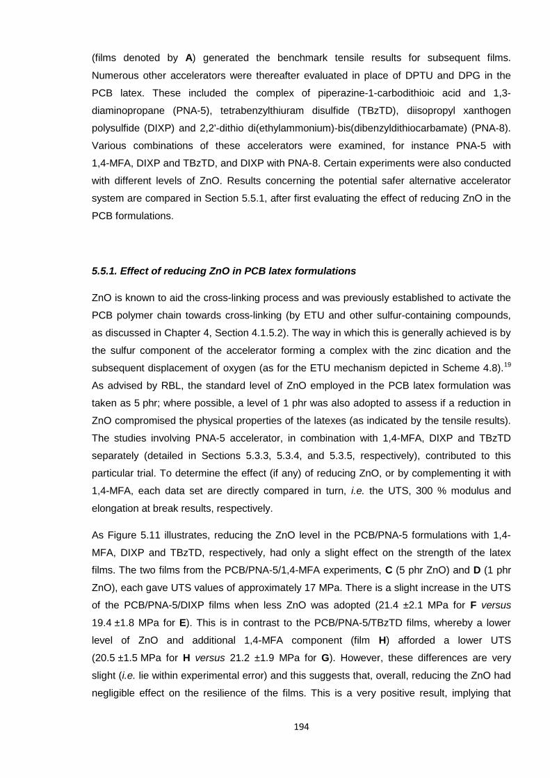
194
(films denoted by A) generated the benchmark tensile results for subsequent films.
Numerous other accelerators were thereafter evaluated in place of DPTU and DPG in the
PCB latex. These included the complex of piperazine-1-carbodithioic acid and 1,3-
diaminopropane (PNA-5), tetrabenzylthiuram disulfide (TBzTD), diisopropyl xanthogen
polysulfide (DIXP) and 2,2'-dithio di(ethylammonium)-bis(dibenzyldithiocarbamate) (PNA-8).
Various combinations of these accelerators were examined, for instance PNA-5 with
1,4-MFA, DIXP and TBzTD, and DIXP with PNA-8. Certain experiments were also conducted
with different levels of ZnO. Results concerning the potential safer alternative accelerator
system are compared in Section 5.5.1, after first evaluating the effect of reducing ZnO in the
PCB formulations.
5.5.1. Effect of reducing ZnO in PCB latex formulations
ZnO is known to aid the cross-linking process and was previously established to activate the
PCB polymer chain towards cross-linking (by ETU and other sulfur-containing compounds,
as discussed in Chapter 4, Section 4.1.5.2). The way in which this is generally achieved is by
the sulfur component of the accelerator forming a complex with the zinc dication and the
subsequent displacement of oxygen (as for the ETU mechanism depicted in Scheme 4.8).19
As advised by RBL, the standard level of ZnO employed in the PCB latex formulation was
taken as 5 phr; where possible, a level of 1 phr was also adopted to assess if a reduction in
ZnO compromised the physical properties of the latexes (as indicated by the tensile results).
The studies involving PNA-5 accelerator, in combination with 1,4-MFA, DIXP and TBzTD
separately (detailed in Sections 5.3.3, 5.3.4, and 5.3.5, respectively), contributed to this
particular trial. To determine the effect (if any) of reducing ZnO, or by complementing it with
1,4-MFA, each data set are directly compared in turn, i.e. the UTS, 300 % modulus and
elongation at break results, respectively.
As Figure 5.11 illustrates, reducing the ZnO level in the PCB/PNA-5 formulations with 1,4-
MFA, DIXP and TBzTD, respectively, had only a slight effect on the strength of the latex
films. The two films from the PCB/PNA-5/1,4-MFA experiments, C (5 phr ZnO) and D (1 phr
ZnO), each gave UTS values of approximately 17 MPa. There is a slight increase in the UTS
of the PCB/PNA-5/DIXP films when less ZnO was adopted (21.4 ±2.1 MPa for F versus
19.4 ±1.8 MPa for E). This is in contrast to the PCB/PNA-5/TBzTD films, whereby a lower
level of ZnO and additional 1,4-MFA component (film H) afforded a lower UTS
(20.5 ±1.5 MPa for H versus 21.2 ±1.9 MPa for G). However, these differences are very
slight (i.e. lie within experimental error) and this suggests that, overall, reducing the ZnO had
negligible effect on the resilience of the films. This is a very positive result, implying that
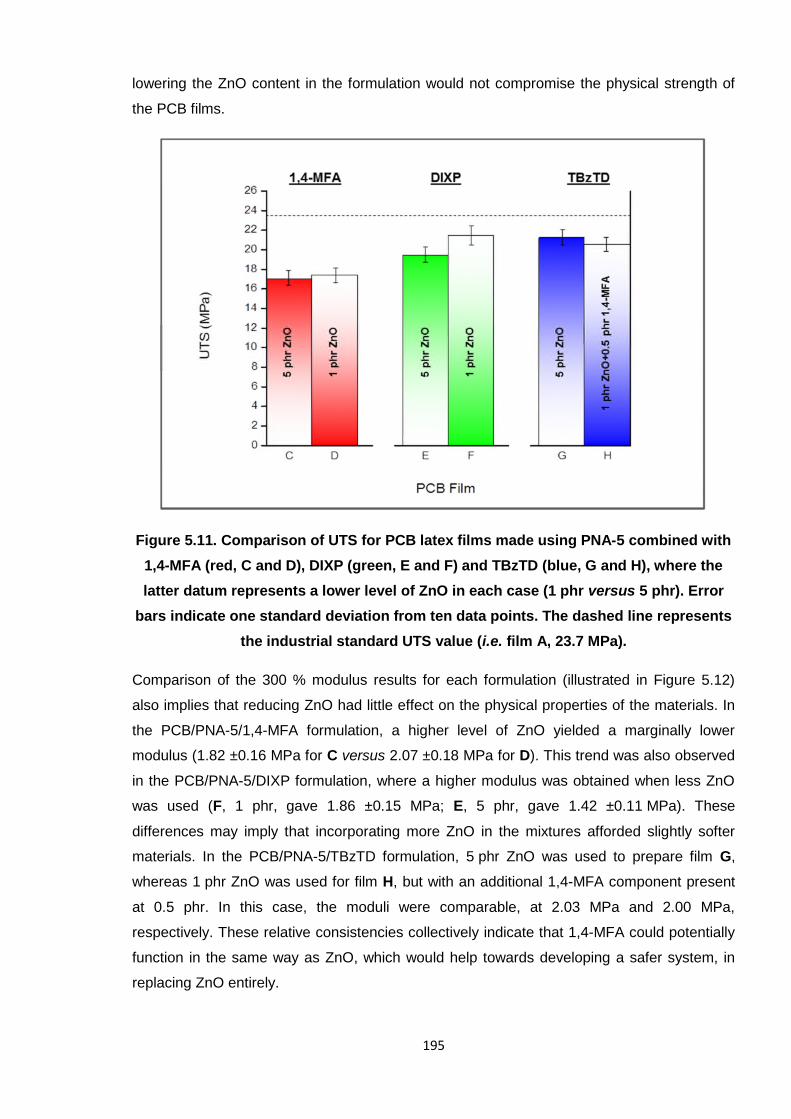
195
lowering the ZnO content in the formulation would not compromise the physical strength of
the PCB films.
Figure 5.11. Comparison of UTS for PCB latex films made using PNA-5 combined with
1,4-MFA (red, C and D), DIXP (green, E and F) and TBzTD (blue, G and H), where the
latter datum represents a lower level of ZnO in each case (1 phr versus 5 phr). Error
bars indicate one standard deviation from ten data points. The dashed line represents
the industrial standard UTS value (i.e. film A, 23.7 MPa).
Comparison of the 300 % modulus results for each formulation (illustrated in Figure 5.12)
also implies that reducing ZnO had little effect on the physical properties of the materials. In
the PCB/PNA-5/1,4-MFA formulation, a higher level of ZnO yielded a marginally lower
modulus (1.82 ±0.16 MPa for C versus 2.07 ±0.18 MPa for D). This trend was also observed
in the PCB/PNA-5/DIXP formulation, where a higher modulus was obtained when less ZnO
was used (F, 1 phr, gave 1.86 ±0.15 MPa; E, 5 phr, gave 1.42 ±0.11 MPa). These
differences may imply that incorporating more ZnO in the mixtures afforded slightly softer
materials. In the PCB/PNA-5/TBzTD formulation, 5 phr ZnO was used to prepare film G,
whereas 1 phr ZnO was used for film H, but with an additional 1,4-MFA component present
at 0.5 phr. In this case, the moduli were comparable, at 2.03 MPa and 2.00 MPa,
respectively. These relative consistencies collectively indicate that 1,4-MFA could potentially
function in the same way as ZnO, which would help towards developing a safer system, in
replacing ZnO entirely.
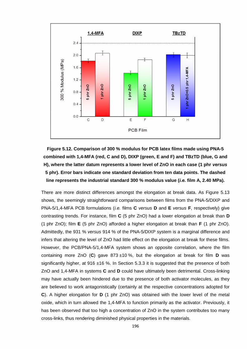
196
Figure 5.12. Comparison of 300 % modulus for PCB latex films made using PNA-5
combined with 1,4-MFA (red, C and D), DIXP (green, E and F) and TBzTD (blue, G and
H), where the latter datum represents a lower level of ZnO in each case (1 phr versus
5 phr). Error bars indicate one standard deviation from ten data points. The dashed
line represents the industrial standard 300 % modulus value (i.e. film A, 2.40 MPa).
There are more distinct differences amongst the elongation at break data. As Figure 5.13
shows, the seemingly straightforward comparisons between films from the PNA-5/DIXP and
PNA-5/1,4-MFA PCB formulations (i.e. films C versus D and E versus F, respectively) give
contrasting trends. For instance, film C (5 phr ZnO) had a lower elongation at break than D
(1 phr ZnO); film E (5 phr ZnO) afforded a higher elongation at break than F (1 phr ZnO).
Admittedly, the 931 % versus 914 % of the PNA-5/DIXP system is a marginal difference and
infers that altering the level of ZnO had little effect on the elongation at break for these films.
However, the PCB/PNA-5/1,4-MFA system shows an opposite correlation, where the film
containing more ZnO (C) gave 873 ±10 %, but the elongation at break for film D was
significantly higher, at 916 ±16 %. In Section 5.3.3 it is suggested that the presence of both
ZnO and 1,4-MFA in systems C and D could have ultimately been detrimental. Cross-linking
may have actually been hindered due to the presence of both activator molecules, as they
are believed to work antagonistically (certainly at the respective concentrations adopted for
C). A higher elongation for D (1 phr ZnO) was obtained with the lower level of the metal
oxide, which in turn allowed the 1,4-MFA to function primarily as the activator. Previously, it
has been observed that too high a concentration of ZnO in the system contributes too many
cross-links, thus rendering diminished physical properties in the materials.
197
The PCB/PNA-5/TBzTD formulation only adds further complications to the comparison of the
elongation at break data; 5 phr ZnO was adopted for film G and 1 phr for film H, but,
crucially, 1,4-MFA was also present in the latter. Here, film G afforded 867 ±11 %, which is
much lower than, and outside the range of error for, film H (928 ±18 %). Unfortunately,
TBzTD was not tested with 1,4-MFA alone, which would have potentially settled this disparity
amongst the data. As such, it is not possible to draw any significant definitive conclusions,
other than to suggest that the effect of a five-fold decrease in ZnO is dependent entirely on
the nature of the accelerator system itself. For example, the one instance where a (slightly)
higher elongation value resulted when a higher level of ZnO was present was in the
PNA-5/DIXP system, where E (5 phr ZnO) yielded 931 % (versus 914 % for F). This was
believed to be the effect of the polysulfide cross-link bridges from DIXP; these chains would
be long and flexible, thus rendering the material highly elastic. For this system, it may be that
the lower elongation of film F (although the values may overlap within the experimental error)
was the result of fewer points on the polymer chain being activated (by less ZnO) and so a
lower quantity of the polysulfide cross-links would exist, thus hindering the elasticity. In
support of this, the UTS value obtained for F is higher than E (21.4 MPa versus 19.4 MPa),
thus proving that more cross-linking did in fact transpire when more ZnO was adopted (in E).
Figure 5.13. Comparison of elongation at break for PCB latex films made using PNA-5
combined with 1,4-MFA (red, C and D), DIXP (green, E and F) and TBzTD (blue, G and
H), where the latter datum represents a lower level of ZnO in each case (1 phr versus
5 phr). Error bars indicate one standard deviation from ten data points. The dashed
line represents the industrial standard elongation at break value (i.e. film A, 861 %).
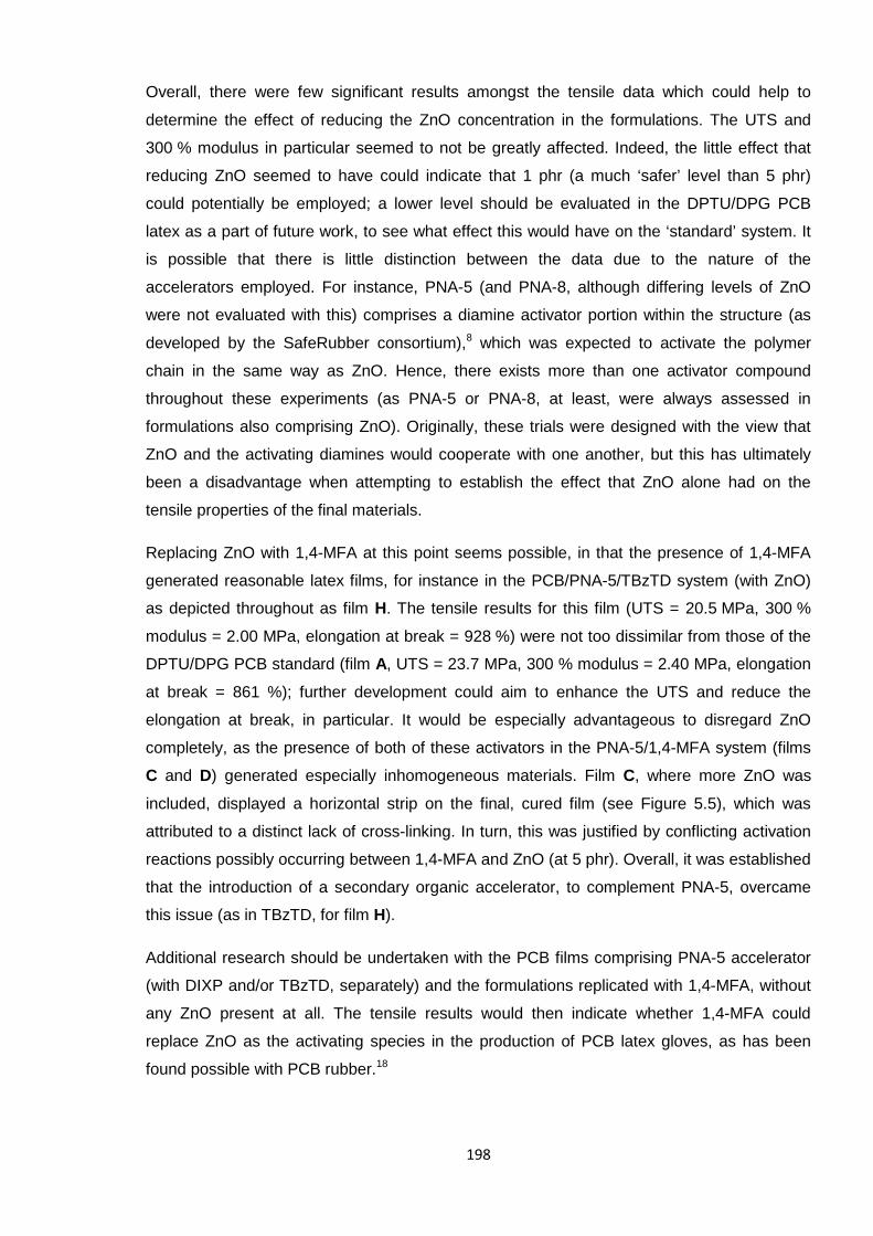
198
Overall, there were few significant results amongst the tensile data which could help to
determine the effect of reducing the ZnO concentration in the formulations. The UTS and
300 % modulus in particular seemed to not be greatly affected. Indeed, the little effect that
reducing ZnO seemed to have could indicate that 1 phr (a much ‘safer’ level than 5 phr)
could potentially be employed; a lower level should be evaluated in the DPTU/DPG PCB
latex as a part of future work, to see what effect this would have on the ‘standard’ system. It
is possible that there is little distinction between the data due to the nature of the
accelerators employed. For instance, PNA-5 (and PNA-8, although differing levels of ZnO
were not evaluated with this) comprises a diamine activator portion within the structure (as
developed by the SafeRubber consortium),8 which was expected to activate the polymer
chain in the same way as ZnO. Hence, there exists more than one activator compound
throughout these experiments (as PNA-5 or PNA-8, at least, were always assessed in
formulations also comprising ZnO). Originally, these trials were designed with the view that
ZnO and the activating diamines would cooperate with one another, but this has ultimately
been a disadvantage when attempting to establish the effect that ZnO alone had on the
tensile properties of the final materials.
Replacing ZnO with 1,4-MFA at this point seems possible, in that the presence of 1,4-MFA
generated reasonable latex films, for instance in the PCB/PNA-5/TBzTD system (with ZnO)
as depicted throughout as film H. The tensile results for this film (UTS = 20.5 MPa, 300 %
modulus = 2.00 MPa, elongation at break = 928 %) were not too dissimilar from those of the
DPTU/DPG PCB standard (film A, UTS = 23.7 MPa, 300 % modulus = 2.40 MPa, elongation
at break = 861 %); further development could aim to enhance the UTS and reduce the
elongation at break, in particular. It would be especially advantageous to disregard ZnO
completely, as the presence of both of these activators in the PNA-5/1,4-MFA system (films
C and D) generated especially inhomogeneous materials. Film C, where more ZnO was
included, displayed a horizontal strip on the final, cured film (see Figure 5.5), which was
attributed to a distinct lack of cross-linking. In turn, this was justified by conflicting activation
reactions possibly occurring between 1,4-MFA and ZnO (at 5 phr). Overall, it was established
that the introduction of a secondary organic accelerator, to complement PNA-5, overcame
this issue (as in TBzTD, for film H).
Additional research should be undertaken with the PCB films comprising PNA-5 accelerator
(with DIXP and/or TBzTD, separately) and the formulations replicated with 1,4-MFA, without
any ZnO present at all. The tensile results would then indicate whether 1,4-MFA could
replace ZnO as the activating species in the production of PCB latex gloves, as has been
found possible with PCB rubber.18
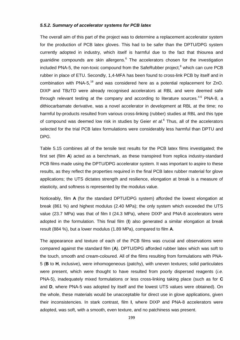
199
5.5.2. Summary of accelerator systems for PCB latex
The overall aim of this part of the project was to determine a replacement accelerator system
for the production of PCB latex gloves. This had to be safer than the DPTU/DPG system
currently adopted in industry, which itself is harmful due to the fact that thiourea and
guanidine compounds are skin allergens.6 The accelerators chosen for the investigation
included PNA-5, the non-toxic compound from the SafeRubber project,8 which can cure PCB
rubber in place of ETU. Secondly, 1,4-MFA has been found to cross-link PCB by itself and in
combination with PNA-5,18 and was considered here as a potential replacement for ZnO.
DIXP and TBzTD were already recognised accelerators at RBL and were deemed safe
through relevant testing at the company and according to literature sources.4-6 PNA-8, a
dithiocarbamate derivative, was a novel accelerator in development at RBL at the time; no
harmful by-products resulted from various cross-linking (rubber) studies at RBL and this type
of compound was deemed low risk in studies by Geier et al.6 Thus, all of the accelerators
selected for the trial PCB latex formulations were considerably less harmful than DPTU and
DPG.
Table 5.15 combines all of the tensile test results for the PCB latex films investigated; the
first set (film A) acted as a benchmark, as these transpired from replica industry-standard
PCB films made using the DPTU/DPG accelerator system. It was important to aspire to these
results, as they reflect the properties required in the final PCB latex rubber material for glove
applications; the UTS dictates strength and resilience, elongation at break is a measure of
elasticity, and softness is represented by the modulus value.
Noticeably, film A (for the standard DPTU/DPG system) afforded the lowest elongation at
break (861 %) and highest modulus (2.40 MPa); the only system which exceeded the UTS
value (23.7 MPa) was that of film I (24.3 MPa), where DIXP and PNA-8 accelerators were
adopted in the formulation. This final film (I) also generated a similar elongation at break
result (884 %), but a lower modulus (1.89 MPa), compared to film A.
The appearance and texture of each of the PCB films was crucial and observations were
compared against the standard film (A). DPTU/DPG afforded rubber latex which was soft to
the touch, smooth and cream-coloured. All of the films resulting from formulations with PNA-
5 (B to H, inclusive), were inhomogeneous (patchy), with uneven textures; solid particulates
were present, which were thought to have resulted from poorly dispersed reagents (i.e.
PNA-5), inadequately mixed formulations or less cross-linking taking place (such as for C
and D, where PNA-5 was adopted by itself and the lowest UTS values were obtained). On
the whole, these materials would be unacceptable for direct use in glove applications, given
their inconsistencies. In stark contrast, film I, where DIXP and PNA-8 accelerators were
adopted, was soft, with a smooth, even texture, and no patchiness was present.
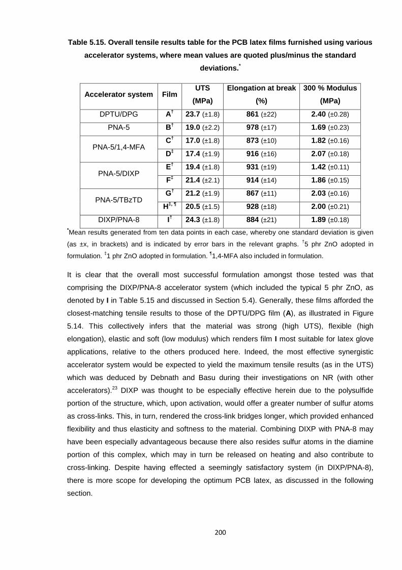
200
Table 5.15. Overall tensile results table for the PCB latex films furnished using various
accelerator systems, where mean values are quoted plus/minus the standard
deviations.*
Accelerator system FilmUTS
(MPa)
Elongation at break
(%)
300 % Modulus
(MPa)
DPTU/DPG A† 23.7 (±1.8) 861 (±22) 2.40 (±0.28)
PNA-5 B† 19.0 (±2.2) 978 (±17) 1.69 (±0.23)
PNA-5/1,4-MFAC† 17.0 (±1.8) 873 (±10) 1.82 (±0.16)
D‡ 17.4 (±1.9) 916 (±16) 2.07 (±0.18)
PNA-5/DIXPE† 19.4 (±1.8) 931 (±19) 1.42 (±0.11)
F‡ 21.4 (±2.1) 914 (±14) 1.86 (±0.15)
PNA-5/TBzTDG† 21.2 (±1.9) 867 (±11) 2.03 (±0.16)
H‡, ¶ 20.5 (±1.5) 928 (±18) 2.00 (±0.21)
DIXP/PNA-8 I† 24.3 (±1.8) 884 (±21) 1.89 (±0.18)
*Mean results generated from ten data points in each case, whereby one standard deviation is given
(as ±x, in brackets) and is indicated by error bars in the relevant graphs.†5 phr ZnO adopted in
formulation.‡1 phr ZnO adopted in formulation.
¶1,4-MFA also included in formulation.
It is clear that the overall most successful formulation amongst those tested was that
comprising the DIXP/PNA-8 accelerator system (which included the typical 5 phr ZnO, as
denoted by I in Table 5.15 and discussed in Section 5.4). Generally, these films afforded the
closest-matching tensile results to those of the DPTU/DPG film (A), as illustrated in Figure
5.14. This collectively infers that the material was strong (high UTS), flexible (high
elongation), elastic and soft (low modulus) which renders film I most suitable for latex glove
applications, relative to the others produced here. Indeed, the most effective synergistic
accelerator system would be expected to yield the maximum tensile results (as in the UTS)
which was deduced by Debnath and Basu during their investigations on NR (with other
accelerators).23 DIXP was thought to be especially effective herein due to the polysulfide
portion of the structure, which, upon activation, would offer a greater number of sulfur atoms
as cross-links. This, in turn, rendered the cross-link bridges longer, which provided enhanced
flexibility and thus elasticity and softness to the material. Combining DIXP with PNA-8 may
have been especially advantageous because there also resides sulfur atoms in the diamine
portion of this complex, which may in turn be released on heating and also contribute to
cross-linking. Despite having effected a seemingly satisfactory system (in DIXP/PNA-8),
there is more scope for developing the optimum PCB latex, as discussed in the following
section.
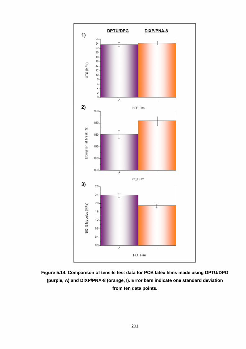
201
Figure 5.14. Comparison of tensile test data for PCB latex films made using DPTU/DPG
(purple, A) and DIXP/PNA-8 (orange, I). Error bars indicate one standard deviation
from ten data points.
202
5.5.3. Further PCB latex development work
This research was the first step for RBL in developing a safe, optimal PCB rubber latex. A
final system cannot be definitively concluded at the time of writing, as there are still many
further studies which should be undertaken, as outlined herein.
Although the PCB/DIXP/PNA-8 system afforded films with tensile properties which correlated
most closely with the standard DPTU/DPG system (amongst those tested), other
formulations also hold some promise. For instance, PNA-5, in combination with DIXP or
TBzTD, afforded reasonable tensile results overall; the UTS values were only slightly lower
than that of film A, where film G (from TBzTD/5 phr ZnO) produced relatively similar
elongation and modulus results, in particular. The PNA-5/1,4-MFA systems (films C and D)
were the least successful formulations, as they offered the lowest UTS values (both
~17 MPa), which shows that these films were the weakest and, thus, would be more
susceptible to tearing. In turn, this proves that PNA-5 requires a secondary (sulfur-based)
organic accelerator component, as 1,4-MFA underperformed (compared to DIXP and
TBzTD). This was attributed to the fact that 1,4-MFA was acting solely as an additional
activator (to ZnO) and was not actually facilitating the cross-links themselves, which would
otherwise be provided by an additional sulfur compound. The main concern for the PNA-5
films, overall, was their appearance and texture, as they all contained patches of particulates,
which most likely compromised the tensile properties. Inspired by this work, future
development by the company will include attempts to optimise the PNA-5 dispersion itself, so
that it can become incorporated more homogeneously into the PCB latex formulation and
thus yield smoother materials. This could mean working with a more dilute dispersion (i.e.
lower than 35 % w/w), mixing for longer or altering the ratios of the accelerators within. To
also optimise the stability of the PNA-5 dispersion (as discussed in Section 5.3.1), a higher
concentration of surfactant may be required; this would certainly need investigating if this
reagent were to be adopted worldwide.
Improvement may also be achieved by combining PNA-5 with a different accelerator; for
instance, it was observed that film H (PNA-5/TBzTD/1,4-MFA) was smoother than film C
(PNA-5/1,4-MFA). Here, the addition of TBzTD to the PNA-5/1,4-MFA formulation seemed to
reduce the inhomogeneity of the films, which was brought about by more cross-linking having
taken place, as all of the reagents were more fully incorporated into the reaction. It would be
worthwhile assessing if PNA-5 and PNA-8 could operate synergistically and generate even
smoother films (which were devoid of patches or particulates, originally caused by PNA-5).
However, it is dubious that this combination would be effective, as both molecules comprise
similar structures, i.e. with a sulfur component and a diamine activator. This work has only
seen a PNA molecule and an organic sulfur compound (such as TBzTD or DIXP) work in
203
unison, where it was perceived that the former would aid in activating the polymer chain,
whilst the latter would be primarily responsible for generating the cross-links. Two PNAs,
which are structurally so similar, might lack in the sulfur composition (atoms) to form
adequate cross-link bridges; PNA-5 and PNA-8 may mostly be concerned with activating the
polymer chain. Thus, an overall reduction in the extent of cross-linking may result and yield
latex films with poor strength and resilience.
More focus is to be directed on the optimum PCB/DIXP/PNA-8 system. For instance, given
that the ancillary aim of this research was to reduce or eliminate ZnO, this film (I) needs
replicating with a lower level of ZnO (i.e. 1 phr). Hereafter, 1,4-MFA should be incorporated
in place of ZnO as a means of determining if this compound is an appropriate alternative
activator. Indeed, it would also be a worthwhile experiment to assess the effect of eradicating
both the MFA and metal oxide; it may be that PNA-8 is able to sufficiently activate the
polymer chain alone, if a high enough concentration is adopted.
Once prospective latex films are identified, the next step is to test for residues through
appropriate solvent extractions. This procedure is well-known at RBL, whereby each film
would be cut into a specific shape/size and immersed into a suitable solvent; the solution
would then be analysed by UV-vis spectroscopy, for instance, after a set time spent agitating.
This is important for determining if the accelerator compounds, in particular, are liable to
leach out of the rubber material; minimal, or ideally no, residue-leaching is crucial for carrying
a system through to large scale industrial production. It is also necessary to assess the
thermal stability of the latex films, which is often termed as ‘aging’ studies (as it is an
indication of how the material will behave over time). In this instance, cured films are
subjected to a specified temperature for set periods of time, whereby tensile tests are then
intermittently undertaken. How the results change over time then dictates the thermal stability
of the latex material. Rattanasom et al. conducted aging studies on silica-loaded PCB latexes
prepared using the standard DPTU/DPG accelerator system and found that the modulus was
found to increase over time.9 Thus, if the modulus was enhanced, and the material rendered
less soft, it could be predicted that the strength and elasticity (UTS and elongation,
respectively) would be compromised. Aging tests are often conducted at temperatures which
far exceed ambient (e.g. 100 °C),9 as much latex application work is undertaken in warm
climate countries, such as in the Far East, and so the material should operate well in these
conditions.
RBL will be continuing with this work and further developing the PCB latex formulation/s
accordingly. This research will also include residues and aging tests, which will be performed
on the eventual PCB films which correlate the closest with current PCB latex standards. The
preliminary study detailed herein has provided RBL with a platform on which to base further
204
trials; the accelerators PNA-5, PNA-8 and DIXP will certainly be taken forward, with the
overall intention to replace DPTU and DPG.
5.6. References
1. H. Ulrich, IntroductiontoIndustrialP olym ers, Hanser, Munich, 1993.2. C. D. Anderson and E. S. Daniels, R AP R A R eview R eports, 2003, 14, Report 160.3. S. H. Wakelin and I. R. White, Clin.Exp.Derm atol., 1999, 24, 245-248.4. D. S. Ohbi, T. S. Purewal, T. Shah and E. Siores, J.Appl.P olym .S ci., 2007, 106, 526-533.5. R. F. Rose, P. Lyons, H. Horne and S. M. Wilkinson, ContactDerm atitis, 2009, 61, 129-137.6. J. Geier, H. Lessmann, W. Uter and A. Schnuch, ContactDerm atitis, 2003, 48, 39-44.7. D. C. Blackley, HighP olym erL atices-T heirS cienceandT echnology.Volum e2:T estingand
Applications, Maclaren & Sons Ltd., London, 1966.8. SafeRubber, http://www.saferubber.eu/, Accessed 11/03/2014.9. N. Rattanasom, P. Kueseng and C. Deeprasertkul, J.Appl.P olym .S ci., 2012, 124, 2657-2668.10. A. A. J. Feast, in P olym erL aticesandtheirApplications, ed. K. O. Calvert, Applied Science
Publishers, London, 1982, pp. 21-46.11. R. S. Chhabra, S. Eustis, J. K. Haseman, P. J. Kurtz and B. D. Carlton, Fundam .Appl.T oxicol.,
1992, 18, 405-417.12. D. M. Smith, Br.J.Ind.M ed., 1984, 41, 362-366.13. D. M. Smith, O ccup.M ed., 1976, 26, 92-94.14. T. Iwase, M. Yamamoto, M. Shirai, F. Akahori, T. Masaoka, T. Takizawa, K. Arishima and Y.
Eguchi, J.Vet.M ed.S ci., 1997, 59, 59-61.15. J. Ashby, M utagenesis, 1986, 1, 3-16.16. C. M. Blow and C. Hepburn, eds., R ubberT echnology andM anufacture, Butterworths,
London, 1982.17. J.-M. Charrier, P olym ericM aterialsandP rocessing:P lastics,Elastom ersandCom posites,
Hanser, New York, 1990.18. K. I. Berry, The Quest for a Safer Accelerator for Polychloroprene Rubber, PhD Thesis, Aston
University, Birmingham, 2013.19. K. I. Berry, M. Liu, K. Chakraborty, N. Pullan, A. West, C. Sammon and P. D. Topham, R ubber
Chem .T echnol., 2014, Accepted.20. K. O. Calvert, in P olym erL aticesandtheirApplications, ed. K. O. Calvert, Applied Science
Publishers, London, 1982, pp. 1-10.21. G. Heideman, J. W. M. Noordermeer and R. N. Datta, R ubberChem .T echnol., 2006, 79, 561-
588.22. V. Zenzen, T. M. Ali, M. Kuproth, H. Zankl, C. Janzowski and G. Eisenbrand, M utat.R es.,
Genet.T oxicol.Environ.M utagen., 2003, 535, 161-170.23. S. C. Debnath and D. K. Basu, J.Appl.P olym .S ci., 1996, 60, 845-855.
205
CHAPTER 6
CONCLUSIONS AND FUTURE WORK
206
6. Conclusions and future work
This chapter provides a synopsis of the research undertaken during this project and
discusses the further work which could benefit each respective area. An outline of the project
as a whole is firstly provided.
6.1. Outline of the project
This PhD project contributed to the SafeRubber enterprise, whereby a Europe-wide
consortium aimed to replace ethylene thiourea (ETU) as the industrial accelerator for cross-
linking poly(2-chloro-1,3-butadiene) (PCB) rubber (commonly known as neoprene). Concerns
over the toxicity of this reagent have arisen, which has put its use, and thus the production of
neoprene, in jeopardy. Hence, the manner in which ETU cross-links PCB required
elucidating, as this was not known before the project commenced. Once this had been
established, alternative, non-toxic cross-linking reagents were evaluated to test the
proficiency of the reaction systems, versus the performance of ETU. The intention was that
the optimum candidate would yield comparable, if not improved, properties in the PCB rubber
and would become a commercialised reagent.
In order to assess the cross-linking mechanism, various reactions were undertaken on PCB
rubber by K. Berry (at Robinson Brothers Ltd.), but solution-state chemical analyses were
difficult due to the high molecular weight of the material. As such, PCB was rendered
completely insoluble once cross-linked; physical (tensile) testing was the primary analytical
method available, as well as FTIR. In contrast, low molecular weight PCB (i.e. oligomers)
was hypothesised to be more straightforward, i) to handle and process, and ii) to analyse by
spectroscopic methods. The polymer in this form was not expected to fully cross-link (like the
rubber), but would become branched, and so the material would remain soluble. Thus, it was
the principal objective of this project to furnish oligomeric PCB in a controlled manner.
Subsequently, the polymer generated this way would be employed in reactions with various
additives to add substance to the mechanistic research being performed by K. Berry with the
rubber.
The second industrial portion of this work concerned PCB in the latex form. Aqueous-based
polymers are adopted in a variety of applications, including coatings, adhesives and in the
production of rubber gloves. It is here where PCB latex is especially relevant; on the whole,
PCB latex gloves are safer than natural rubber (NR) equivalents and so are widely applied
throughout the professions. However, in a similar way to the ETU/PCB rubber issue, the
standard chemicals employed to cross-link PCB latex, namely diphenyl guanidine (DPG) and
diphenyl thiourea (DPTU), are known skin allergens. Hence, alternative, safer reagents are
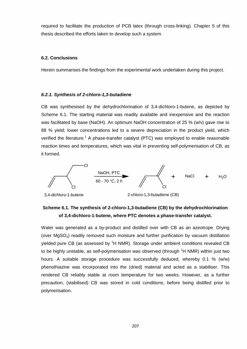
207
required to facilitate the production of PCB latex (through cross-linking). Chapter 5 of this
thesis described the efforts taken to develop such a system.
6.2. Conclusions
Herein summarises the findings from the experimental work undertaken during this project.
6.2.1. Synthesis of 2-chloro-1,3-butadiene
CB was synthesised by the dehydrochlorination of 3,4-dichloro-1-butene, as depicted by
Scheme 6.1. The starting material was readily available and inexpensive and the reaction
was facilitated by base (NaOH). An optimum NaOH concentration of 25 % (w/v) gave rise to
88 % yield; lower concentrations led to a severe depreciation in the product yield, which
verified the literature.1 A phase-transfer catalyst (PTC) was employed to enable reasonable
reaction times and temperatures, which was vital in preventing self-polymerisation of CB, as
it formed.
Scheme 6.1. The synthesis of 2-chloro-1,3-butadiene (CB) by the dehydrochlorination
of 3,4-dichloro-1-butene, where PTC denotes a phase-transfer catalyst.
Water was generated as a by-product and distilled over with CB as an azeotrope. Drying
(over MgSO4) readily removed such moisture and further purification by vacuum distillation
yielded pure CB (as assessed by 1H NMR). Storage under ambient conditions revealed CB
to be highly unstable, as self-polymerisation was observed (through 1H NMR) within just two
hours. A suitable storage procedure was successfully deduced, whereby 0.1 % (w/w)
phenothiazine was incorporated into the (dried) material and acted as a stabiliser. This
rendered CB reliably stable at room temperature for two weeks. However, as a further
precaution, (stabilised) CB was stored in cold conditions, before being distilled prior to
polymerisation.
Cl
H2ONaClNaOH, PTC
60 - 70 °C, 2 h
Cl
Cl
2-chloro-1,3-butadiene (CB)3,4-dichloro-1-butene
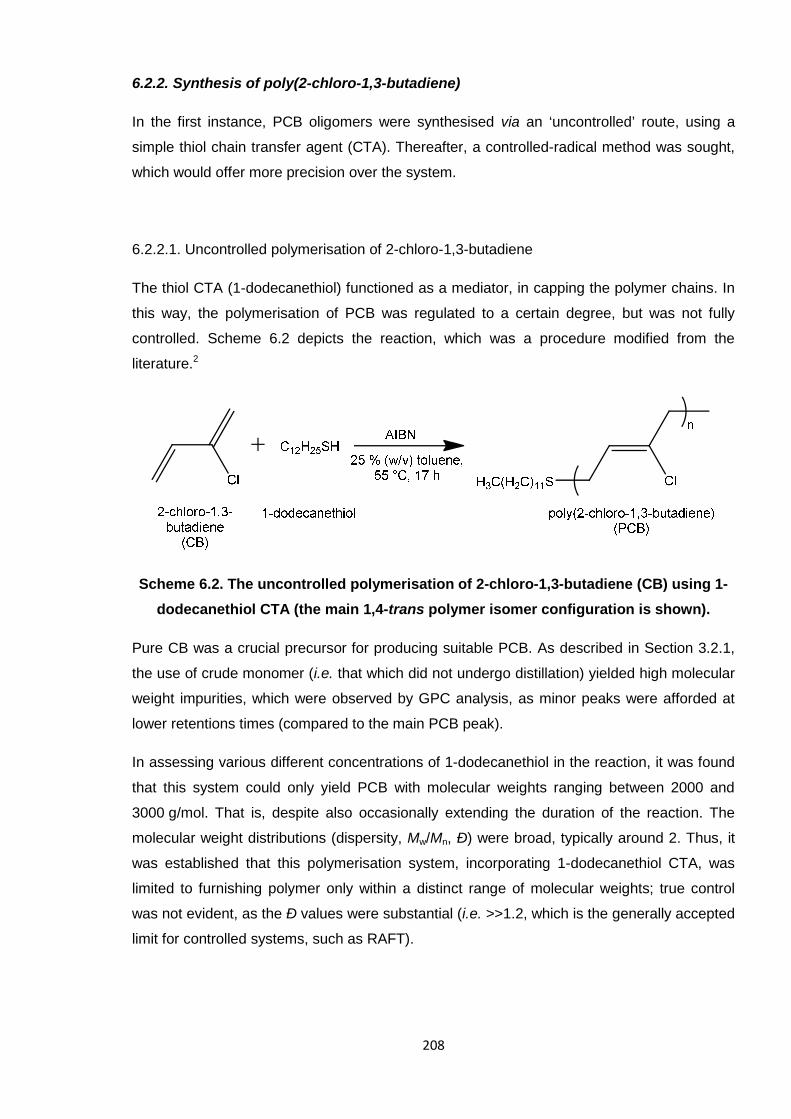
208
6.2.2. Synthesis of poly(2-chloro-1,3-butadiene)
In the first instance, PCB oligomers were synthesised via an ‘uncontrolled’ route, using a
simple thiol chain transfer agent (CTA). Thereafter, a controlled-radical method was sought,
which would offer more precision over the system.
6.2.2.1. Uncontrolled polymerisation of 2-chloro-1,3-butadiene
The thiol CTA (1-dodecanethiol) functioned as a mediator, in capping the polymer chains. In
this way, the polymerisation of PCB was regulated to a certain degree, but was not fully
controlled. Scheme 6.2 depicts the reaction, which was a procedure modified from the
literature.2
Scheme 6.2. The uncontrolled polymerisation of 2-chloro-1,3-butadiene (CB) using 1-
dodecanethiol CTA (the main 1,4-trans polymer isomer configuration is shown).
Pure CB was a crucial precursor for producing suitable PCB. As described in Section 3.2.1,
the use of crude monomer (i.e. that which did not undergo distillation) yielded high molecular
weight impurities, which were observed by GPC analysis, as minor peaks were afforded at
lower retentions times (compared to the main PCB peak).
In assessing various different concentrations of 1-dodecanethiol in the reaction, it was found
that this system could only yield PCB with molecular weights ranging between 2000 and
3000 g/mol. That is, despite also occasionally extending the duration of the reaction. The
molecular weight distributions (dispersity, Mw/Mn, Ð) were broad, typically around 2. Thus, it
was established that this polymerisation system, incorporating 1-dodecanethiol CTA, was
limited to furnishing polymer only within a distinct range of molecular weights; true control
was not evident, as the Ð values were substantial (i.e. >>1.2, which is the generally accepted
limit for controlled systems, such as RAFT).
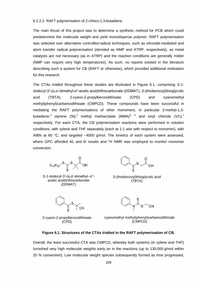
209
6.2.2.2. RAFT polymerisation of 2-chloro-1,3-butadiene
The main thrust of this project was to determine a synthetic method for PCB which could
predetermine the molecular weight and yield monodisperse polymer. RAFT polymerisation
was selected over alternative controlled-radical techniques, such as nitroxide-mediated and
atom transfer radical polymerisation (denoted as NMP and ATRP, respectively), as metal
catalysts are not necessary (as in ATRP) and the reaction conditions are generally milder
(NMP can require very high temperatures). As such, no reports existed in the literature
describing such a system for CB (RAFT or otherwise), which provided additional motivation
for this research.
The CTAs trialled throughout these studies are illustrated in Figure 6.1, comprising S-1-
dodecyl-S′-(α,α′-dimethyl-α′′-acetic acid)trithiocarbonate (DDMAT), S-(thiobenzoyl)thioglycolic
acid (TBTA), 2-cyano-2-propylbenzodithioate (CPD) and cyanomethyl
methyl(phenyl)carbamodithioate (CMPCD). These compounds have been successful in
mediating the RAFT polymerisations of other monomers, in particular 2-methyl-1,3-
butadiene,3 styrene (St),4 methyl methacrylate (MMA)5, 6 and vinyl chloride (VC),7
respectively. For each CTA, the CB polymerisation reactions were performed in solution
conditions, with xylene and THF separately (each at 1:1 w/w with respect to monomer), with
AIBN at 60 °C, and targeted ~4000 g/mol. The kinetics of each system were assessed,
where GPC afforded Mn and Ð results and 1H NMR was employed to monitor monomer
conversion.
Figure 6.1. Structures of the CTAs trialled in the RAFT polymerisation of CB.
Overall, the least successful CTA was CMPCD, whereby both systems (in xylene and THF)
furnished very high molecular weights early on in the reactions (up to 130,000 g/mol within
20 % conversion). Low molecular weight species subsequently formed as time progressed,
S-(thiobenzoyl)thioglycolic acid(TBTA)
S-1-dodecyl-S′-(α,α′-dimethyl- α′′-acetic acid)trithiocarbonate
(DDMAT)
2-cyano-2-propylbenzodithioate(CPD)
cyanomethyl methyl(phenyl)carbamodithioate(CMPCD)
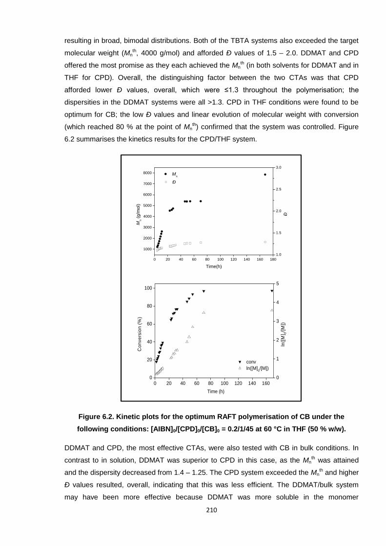
210
resulting in broad, bimodal distributions. Both of the TBTA systems also exceeded the target
molecular weight (Mnth, 4000 g/mol) and afforded Ð values of 1.5 – 2.0. DDMAT and CPD
offered the most promise as they each achieved the Mnth (in both solvents for DDMAT and in
THF for CPD). Overall, the distinguishing factor between the two CTAs was that CPD
afforded lower Ð values, overall, which were ≤1.3 throughout the polymerisation; the
dispersities in the DDMAT systems were all >1.3. CPD in THF conditions were found to be
optimum for CB; the low Ð values and linear evolution of molecular weight with conversion
(which reached 80 % at the point of Mnth) confirmed that the system was controlled. Figure
6.2 summarises the kinetics results for the CPD/THF system.
Figure 6.2. Kinetic plots for the optimum RAFT polymerisation of CB under the
following conditions: [AIBN]0/[CPD]0/[CB]0 = 0.2/1/45 at 60 °C in THF (50 % w/w).
DDMAT and CPD, the most effective CTAs, were also tested with CB in bulk conditions. In
contrast to in solution, DDMAT was superior to CPD in this case, as the Mnth was attained
and the dispersity decreased from 1.4 – 1.25. The CPD system exceeded the Mnth and higher
Ð values resulted, overall, indicating that this was less efficient. The DDMAT/bulk system
may have been more effective because DDMAT was more soluble in the monomer
0 20 40 60 80 100 120 140 1600
20
40
60
80
100
conv
Co
nve
rsio
n(%
)
Time (h)
0
1
2
3
4
5
ln([M]0/[M])
ln([
M] 0
/[M
])
0 20 40 60 80 100 120 140 160 180
1000
2000
3000
4000
5000
6000
7000
8000 Mn
Mn
(g/m
ol)
Time(h)
1.0
1.5
2.0
2.5
3.0
Ð
Ð
211
(compared to CPD). Thus, the CPD/THF system remained the optimum system, of all of the
conditions tested, as the dispersity remained low throughout the entire polymerisation (Ð
≤1.3). This system was further evaluated by isolating a sample of macroCTA and performing
a self-blocking experiment. Chain end fidelity was proven as the subsequent reaction with a
second portion of CB saw an increase in the molecular weight and the final (extended)
polymer retained a low Ð. Furthermore, higher molecular weights were targeted by altering
the monomer:CTA ratio; up to ~50,000 g/mol, low dispersity PCB was synthesised by this
method.8
The success of CPD was attributed to the nature of the R group, C(Me)2CN, which yields a
superior, stable tertiary radical and is an effective leaving group.9 Incorporating this CTA into
a RAFT reaction (depending on the monomer application) is understood to enable faster
rates of fragmentation, which in turn facilitates enhanced control over polymerisation.
The most noticeable effect of solution conditions (compared to bulk) was that reactions
proceeded considerably slower. This is not unusual and can be attributed to the diminished
monomer concentration. Xylene and THF were compared, which are vastly different solvents
in terms of polarity and chemical structure. In general, slower polymerisations occurred in
THF, which in turn seemed to offer more control. For instance, THF was even found to
improve the CMPCD system, as xylene yielded bimodal GPC peaks, whereas those from
THF were unimodal (albeit broad/tailing). This was a similar phenomenon to that of DDMAT,
where more uniform GPC peaks arose in THF. For the optimum CTA (CPD) the Mnth was
attained at high conversion in THF, but less control was evident in xylene as this value
(4000 g/mol) was exceeded. Overall, it was concluded that CB could have a greater affinity
for THF, which may justify why superior control was shown in these conditions. Also, it is
possible that the reagents, namely CPD and AIBN, were more soluble in THF (than in
xylene).
A further conclusion was drawn from this work, in classifying CB as a more-activated
monomer (MAM). This derives from the apparent applicability (and inapplicability) of certain
CTAs in the RAFT polymerisations of this monomer. For instance, CMPCD was clearly
unsuccessful for CB, but was trialled initially because of the reported success of this with VC
(i.e. a chlorinated vinyl molecule), which is defined as a less-activated monomer (LAM).7
LAMs and MAMs are classified according to the reactivity of the associated growing polymer
propagating radical; poly(MAM)s have effective homolytic leaving groups, whereas
poly(LAM)s are poor. Furthermore, MAMs comprise carbon-carbon double bonds which are
conjugated to an aromatic ring, carbonyl or cyano group; this bond in a LAM is situated
adjacent to a hetero-aromatic ring, a nitrogen lone pair or a saturated carbon or oxygen.10
Hence, the conjugation that exists between the two double bonds in the CB structure would
212
suggest that this is a MAM, by definition. The relatively successful control offered by DDMAT
in these experiments adds weight to this argument, as trithiocarbonates are known to be
effective CTAs for MAMs.11 Also, CPD, the CTA of the final optimum CB system, was
effective for MMA, which is also a MAM. Collectively, the results certainly imply that CB is a
MAM, with respect to such classification within the realm of RAFT chemistry.
6.2.3. Industrial applications of poly(2-chloro-1,3-butadiene)
The introduction to this chapter (Section 6.1) described how it was important to perform
cross-linking experiments on low molecular weight PCB, so as to ultimately define the
mechanism by which ETU reacts. It was intended for PCB furnished via RAFT polymerisation
to be employed in these investigations, but this was not feasible as this work had to
complement that in RBL and, thus, be undertaken promptly. As a result, the ~3000 g/mol
PCB generated from the uncontrolled method was adopted.
A separate, yet related, study concerned the development of a safer accelerator system for
PCB latex. As with ETU in the rubber, RBL were looking to replace DPG and DPTU as the
components in a standard industrial PCB latex accelerator system. Thus, PCB latex films
were furnished using various non-hazardous compounds. Comparison of the tensile test
results of the development films, with those from a DPG/DPTU system, ultimately revealed
serious contenders (in replacing DPG and DPTU), as the physical properties of certain
materials were analogous.
6.2.3.1. Cross-linking poly(2-chloro-1,3-butadiene)
Low molecular weight (oligomeric) PCB was employed in reactions with ETU and ZnO,
separately and in unison, which aimed to imitate the cross-linking system employed in
industry with the rubber material. PCB was subsequently reacted with model compounds (in
the absence and presence of ZnO), including piperazine (PIP), 1,4-diaminobutane (DAB),
dibutyl thiourea (DBTU) and 1,8-octanedithiol (ODT), and an alternative accelerator,
tetrabutylthiuram disulfide (TbuT). The intention of this approach was to deduce which
functionality of ETU was involved in the cross-linking, i.e. through the sulfur, nitrogen or
carbon atoms. Reactions were undertaken at the appropriate temperature (160 °C) and were
monitored by periodic FTIR spectroscopic analyses (NMR and GPC techniques unfortunately
yielded no beneficial data which added to the results).
Allylic rearrangement of the 1,2-PCB isomer was verified as the primary stage of the cross-
linking mechanism. This was found by observing the associated FTIR peak, at ~925 cm-1,
213
which diminished over time; the presence of ZnO accelerated this process considerably. This
trend was observed in the experiments with ETU, model compounds and TbuT.
Various existing cross-linking theories were disproved, such as the possibility of ether
linkage12 and those of Vukov13 and Desai,14 who each implied that ZnCl2 was a distinct by-
product of the reaction with ZnO. However, it was eventually postulated that ZnCl2 was
indeed generated, after all, when ETU and ZnO were employed in a combined system. In the
oligomeric PCB reaction with both of these reagents, a white solid precipitated from the
solution; this was found to be the (unidentified) product of a reaction between ZnCl2 and
ETU. Thus, this further implied that ZnCl2 was generated in situ during the reaction and was
subsequently involved in another reaction. Additionally, EU was furnished as a by-product in
the rubber cross-linking investigations of Berry,15 although this was not replicated in the
oligomer studies. Overall, this helped to substantiate the theory of Pariser.16
During these studies, the oligomeric form of PCB was particularly advantageous, not least of
all because the material was more practical, but also as this made the detection of by-
products possible. For instance, hydrochloride gas (HCl) was evolved in the PCB/ETU
reaction, which in turn helped to support the bis-alkylation theory of Kovacic (as this emits
HCl after forming cross-links via the nitrogen atoms).17 Cross-linking with alternative
compounds, such as the diamines (PIP, DAB and DBTU), in contrast, produced alkaline
vapours, which was ultimately linked to the formation of HCl salts. These findings were
reinforced by the relevant FTIR spectra, as new peaks were formed in the 1600 – 1500 cm-1
region. This work was crucial as the testing for evolved gases, for instance, was not possible
during the rubber investigations of Berry,15 where the reactions took place under high
pressure in an enclosed rheometer machine.
ZnO was integral to the mechanism and ultimately enabled cross-linking to occur through the
sulfur atoms of certain molecules. ODT could not facilitate the cross-linking of PCB by itself
(in oligomers or rubber) but was successful when ZnO was present. Changes in the FTIR
spectra of the TbuT reactions revealed that the N−C=S functionality was disrupted more
readily with ZnO and a new peak at 1560 cm-1 indicated the formation of C−S bonds. Hence,
the conclusion was made that ZnO was enabling cross-linking through sulfur; it is perceived
that this is facilitated by the Zn2+ dication.
Overall, this work indicated that more than one mechanism occurs when PCB is cross-linked
with ETU and ZnO. The bis-alkylation theory of Kovacic17 was validated by the clear
formation of HCl (in conditions comprising ETU). Subsequently, the Pariser mechanism16
seems likely as ZnCl2 and EU by-products have been detected (although EU was only found
in the rubber experiments) and C−S bonds form. However, it is clear that ETU cannot react
directly with the polymer chain through the sulfur atom as results were negative when dithiols
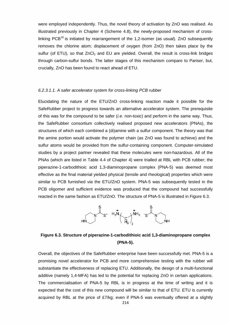
214
were employed independently. Thus, the novel theory of activation by ZnO was realised. As
illustrated previously in Chapter 4 (Scheme 4.8), the newly-proposed mechanism of cross-
linking PCB18 is initiated by rearrangement of the 1,2-isomer (as usual). ZnO subsequently
removes the chlorine atom; displacement of oxygen (from ZnO) then takes place by the
sulfur (of ETU), so that ZnCl2 and EU are yielded. Overall, the result is cross-link bridges
through carbon-sulfur bonds. The latter stages of this mechanism compare to Pariser, but,
crucially, ZnO has been found to react ahead of ETU.
6.2.3.1.1. A safer accelerator system for cross-linking PCB rubber
Elucidating the nature of the ETU/ZnO cross-linking reaction made it possible for the
SafeRubber project to progress towards an alternative accelerator system. The prerequisite
of this was for the compound to be safer (i.e. non-toxic) and perform in the same way. Thus,
the SafeRubber consortium collectively realised proposed new accelerators (PNAs), the
structures of which each combined a (di)amine with a sulfur component. The theory was that
the amine portion would activate the polymer chain (as ZnO was found to achieve) and the
sulfur atoms would be provided from the sulfur-containing component. Computer-simulated
studies by a project partner revealed that these molecules were non-hazardous. All of the
PNAs (which are listed in Table 4.4 of Chapter 4) were trialled at RBL with PCB rubber; the
piperazine-1-carbodithioic acid 1,3-diaminopropane complex (PNA-5) was deemed most
effective as the final material yielded physical (tensile and rheological) properties which were
similar to PCB furnished via the ETU/ZnO system. PNA-5 was subsequently tested in the
PCB oligomer and sufficient evidence was produced that the compound had successfully
reacted in the same fashion as ETU/ZnO. The structure of PNA-5 is illustrated in Figure 6.3.
Figure 6.3. Structure of piperazine-1-carbodithioic acid 1,3-diaminopropane complex
(PNA-5).
Overall, the objectives of the SafeRubber enterprise have been successfully met. PNA-5 is a
promising novel accelerator for PCB and more comprehensive testing with the rubber will
substantiate the effectiveness of replacing ETU. Additionally, the design of a multi-functional
additive (namely 1,4-MFA) has led to the potential for replacing ZnO in certain applications.
The commercialisation of PNA-5 by RBL is in progress at the time of writing and it is
expected that the cost of this new compound will be similar to that of ETU. ETU is currently
acquired by RBL at the price of £7/kg; even if PNA-5 was eventually offered at a slightly
215
higher rate, the benefits of this new cross-linker molecule being non-toxic, with a similar
performance, would still render this a viable replacement within industry.
6.2.3.2. Poly(2-chloro-1,3-butadiene) latex development
In a similar way to the PCB cross-linking studies which centred on ETU, the second industrial
portion of this project concerned the development of PCB rubber in the latex form (as
detailed in Chapter 5). In this case, the hazardous nature of the diphenyl thiourea (DPTU)
and diphenyl guanidine (DPG) accelerators adopted in industry was the concern and
alternative reagents were sought.
Variations of accelerator systems comprising the complex of piperazine-1-carbodithioic acid
and 1,3-diaminopropane (PNA-5), tetrabenzylthiuram disulfide (TBzTD), diisopropyl
xanthogen polysulfide (DIXP) and 2,2'-dithio di(ethylammonium)-
bis(dibenzyldithiocarbamate) (PNA-8) were employed to produce PCB latex films; tensile test
results were compared against those of a standard DPTU/DPG film (depicted as A
throughout), which acted as a benchmark. Different levels of ZnO activator (namely, 5 phr
versus 1 phr) were also evaluated, as was the performance of a multi-functional additive
(1,4-MFA). A secondary aim was to develop a method which would reduce the level of ZnO
is the system, or eradicate it completely. The findings from these trials are summarised in the
following sub-sections.
6.2.3.2.1. The effect of ZnO in PCB latex films
ZnO is known to act as an activator in terms of cross-linking and was found to initiate the
process for ETU (in PCB rubber and oligomers) in the novel mechanism proposed by
Berry et al.18 ZnO was considered to operate in the same way in the latex systems, by
enabling the sulfur-containing accelerator components to react with polymer chains. Certain
formulations, namely those involving PNA-5 in combination with 1,4-MFA (films C and D),
DIXP (films E and F) and TBzTD (films G and H), compared higher and lower concentrations
of ZnO. To note, 1,4-MFA was an additional component within H, which included 1 phr ZnO.
Overall, reducing the quantity of ZnO in the formulation had negligible effect on the strength
(UTS) of the PCB films, which was a positive result regarding the capacity for adopting a
lower concentration. However, it was postulated that a higher level could enhance the
softness of the materials, as E (5 phr ZnO, 1.42 ±0.11 MPa) yielded a lower modulus than F
(1 phr ZnO, 1.86 ±0.15 MPa). The modulus results also indicated that 1,4-MFA could
potentially function in the same way as ZnO, as the value for H (incorporating 1 phr ZnO and
216
0.5 phr 1,4-MFA) was comparable to G (5 phr ZnO), at approximately 2 MPa. Elongation at
break data also revealed few trends and the only possible conclusions were associated with
the nature of the accelerator (as discussed subsequently in Section 6.2.3.2.2). Overall, it was
established that a five-fold decrease in the concentration of ZnO was viable for a PCB latex
formulation, certainly for the conditions adopted herein.
In assessing 1,4-MFA as a potential alternative to ZnO, it was found that the presence of
both of these activators in a system was detrimental if only one organic accelerator was
present. For instance, films C and D, produced through PNA-5/1,4-MFA and contrasting
levels of ZnO (5 phr in C, 1 phr in D), afforded very low UTS results, around 17 MPa. Such
low strengths were attributed to the antagonistic nature of the dual activator system; ZnO and
1,4-MFA were believed to be competing in order to activate the polymer chains and, as such,
less cross-linking resulted. In D, with less ZnO, the UTS and elongation were higher
(differences in the latter data were more distinct, i.e. 916 % versus 873 % for C), which
indicated that more cross-links were formed from this system. This was justified by 1,4-MFA
being able to act as the major activator and so more cross-linking occurred. Further evidence
for this came from qualitative assessments of the films, as the inhomogeneity of film C
seemed to arise from excess ZnO being present (as less was incorporated into cross-linking
reactions).
6.2.3.2.2. New accelerators for the production of PCB latex films
The success of PNA-5 in cross-linking PCB rubber and oligomers (highlighted in Section
4.1.6) justified trialling this substance in the latex systems. In summary, this accelerator
performed poorly when adopted by itself (as in film B) and when combined with 1,4-MFA
(with ZnO). PCB films produced this way yielded low UTS values, compared to the standard
DPTU/DPG system (A), which was attributed to fewer cross-links being materialised. Film B
was an especially thin material, which resulted from a drastically reduced concentration of
accelerator in the formulation; a high elongation at break reflected that fewer cross-links were
present, which would otherwise render the film more rigid.
On combining PNA-5 with a secondary sulfur-containing organic accelerator molecule the
systems were vastly improved. For instance, the UTS was increased when DIXP and TBzTD
were united (separately) with PNA-5 and the inhomogeneity of these films was not as severe.
It was clear that more cross-linking was taking place when two organic accelerators were
being employed and that they functioned in a synergistic manner. In support of this, film H,
from the PNA-5/TBzTD system with ZnO and 1,4-MFA, was an improvement on D, where
PNA-5 was used alone with 1,4-MFA (where both adopted 1 phr ZnO). The physical
217
properties and appearance of H were superior to D because the dual accelerator system
(PNA-5 and TBzTD) operated more effectively alongside the two activators (ZnO and 1,4-
MFA). Thus, activation was occurring simultaneously and cross-linking was being facilitated
more efficiently.
Film I, which incorporated PNA-8 and DIXP accelerators and 5 phr ZnO, was particularly
significant to these studies as optimum tensile results were generated, which correlated
closely with those from A (the standard system). By eradicating PNA-5 from the formulation,
the final material became smooth and free from inhomogeneous patches, which, as a result,
rendered the film strong (UTS = 24.3 ±1.8 MPa). This film was elastic and soft due to the
presence of highly flexible sulfur-based cross-links; the polysulfide portion of DIXP was
deemed to provide more sulfur atoms (than other molecules), which made the cross-link
bridges longer than in any of the other systems. At this point, the PNA-8/DIXP system seems
to be a contender for replacing the industrial (hazardous) DPTU/DPG standard.
6.3. Future work
The following sections describe the experimental work which should succeed this project,
considering the progress which has been made to-date (previously summarised).
6.3.1. Further development of the 2-chloro-1,3-butadiene synthetic protocol
Overall, the dehydrochlorination reaction adopted to synthesise CB was highly capricious, in
that variable yields were observed throughout, irrespective of the reaction conditions. As
highlighted in Section 3.1.3, on the occasions when two comparable syntheses were
undertaken, the final product yields would never compare. Overall, yields varied within
approximately 20 – 90 %. It is possible that the rate of stirring (of the reaction mixture) was a
factor, as a slower speed may have caused inadequate mixing of reagents and ultimately
resulted in lower yields. It is unlikely, though, that this can be held solely accountable for
such dramatic differences.
Higher concentrations of the base should be assessed to firstly establish if higher yields can
be obtained this way (i.e. >88 %, which was acquired with 25 % w/w NaOH). This may also
contribute to resolving the variable yields issue, as this particular variable may not actually be
optimum at this 25 % (w/w) level and, once rectified, the entire process could be made more
reliable.
218
6.3.2. Future studies for the RAFT polymerisation of 2-chloro-1,3-butadiene
Successful RAFT polymerisation conditions for CB have been deduced which can predefine
low dispersity PCB up to 50,000 g/mol. However, it was not necessary for this work to target
higher than this; a part of future work should be to probe this system further so as to attain
higher molecular weights (i.e. >50,000 g/mol). The synthesis of relatively large polymers in a
controlled manner is potentially useful for industrial applications and this RAFT reaction
would be a relatively straightforward set-up for adopting on a large scale (i.e. few, simple
reagents and moderate temperature).
It is possible that an alternative initiator (to AIBN), and/or concentration of such, may also be
suitable for the RAFT polymerisation of CB. The low boiling point of this monomer (62 °C)
does, however, limit the options. It would be especially advantageous to successfully design
a low-temperature reaction system, which would in turn be even more viable for industry.
This system should perform as successfully, if not more so, than the AIBN/60 °C system,
with CPD in THF. Lauroyl peroxide is a possible candidate, as this initiator can be used at
temperatures as low as 40 °C.
It would be ideal to also evaluate a wider range of solvents, and concentrations thereof, in
the RAFT system. THF was found to offer more control over the polymerisation of CB than
xylene, and bulk systems were more rapid but compromised the values of Ð. Thus, one
approach could involve simply altering the concentration of THF in the system, i.e. assess
solutions comprising up to 50 % (or 1:1 w/w), so that a compromise between optimal
dispersities and reaction times could be realised. Likewise, an altogether different solvent
could be as or more effective. A variety of solvents should be tested, over a range of
polarities, densities, chemical reactivities, etc, so that a more comprehensive catalogue of
results was realised. Only then could more definitive conclusions be made regarding the
effect of solvent in RAFT polymerisation, at least with CB.
6.3.3. Optimisation of oligomer cross-linking experiments
Employing low molecular weight (oligomeric) material contributed significantly to the cross-
linking studies surrounding PCB, on the whole. For instance, it was possible to observe
certain by-products of the reactions, which in turn enabled the ETU/ZnO mechanism to be
deduced. Hence, complete optimisation of the oligomer experiments should be considered
for future trials of this nature, so that future research can be conducted more efficiently.
Ethylene urea (EU) was not detected during the oligomer ETU/ZnO reaction but the
equivalent trial with rubber (by K. Berry)15 did prevail. It is not clear why the latter experiment
219
was more successful at this; incorporating the reagents through milling could have been a
more proficient mixing process. Sonicating the oligomer mixtures may not, therefore, have
been sufficient; a more rigorous mixing procedure should be sought, so that the reagents are
mixed more thoroughly to be fully involved in the reaction (with PCB). Furthermore, the FTIR
results should be supplemented by other analytical data. For instance, a specialised, high
resolution 1H NMR spectroscopic method, or HPLC/LC-MS techniques, may offer more
insight into the cross-linking mechanism and contribute more knowledge to these systems.
6.3.4. Further development of poly(2-chloro-1,3-butadiene) latex
Further research is to take place at RBL for the production of PCB latex films in the absence
of ZnO, entirely. The full capabilities of 1,4-MFA will be assessed (as a replacement to ZnO)
by adopting this compound alone in certain systems, including the standard DPTU/DPG
formulation. Further work in this area should also include evaluating PNA-8/DIXP (the most
promising system of those tested) with less ZnO (i.e. 1 phr) and with 1,4-MFA (without ZnO);
results from such trials would indicate whether reducing or replacing ZnO was possible for
this particular formulation.
Each PCB latex film which was synthesised with PNA-5 was rendered inhomogeneous,
containing various extents of patches of particulates. Thus, should work continue with this
accelerator, the dispersion itself would have to be developed further. It may be necessary to
reduce the concentration of the dispersion (i.e. <35 % w/w), so that the solids content is
reduced, or to increase the quantity of surfactant present. More surfactant would be
anticipated to improve the (thermal) stability of the reagent, as an elevated temperature
(40 °C) drastically compromised the stability during this research, as shown by distinct
increases in viscosity over time (as discussed in Chapter 5).
Additional experiments on the rubber films are also necessary, such as in performing solvent
extractions to determine any accelerator residues, and undertaking aging studies to
understand the thermal stability of the materials. Such trials should proceed on films which
possess the most favourable tensile properties or those most closely matching the industry
standard material. Ideally, no (or minimal) residues would be liberated from the new PCB
latex (which would otherwise cause harm to the glove-wearer) and the physical (tensile)
properties would not be compromised over time.
220
6.4. References
1. EP P at.,0001905, 1978.2. U S P at.,5523355, 1996.3. D. S. Germack and K. L. Wooley, J.P olym .S ci.,P artA:P olym .Chem ., 2007, 45, 4100-4108.4. S. C. Farmer and T. E. Patten, J.P olym .S ci.,P artA:P olym .Chem ., 2002, 40, 555-563.5. Y. K. Chong, J. Krstina, T. P. T. Le, G. Moad, A. Postma, E. Rizzardo and S. H. Thang,
M acrom olecules, 2003, 36, 2256-2272.6. M. Benaglia, E. Rizzardo, A. Alberti and M. Guerra, M acrom olecules, 2005, 38, 3129-3140.7. C. M. R. Abreu, P. V. Mendonça, A. C. Serra, J. F. J. Coelho, A. V. Popov, G. Gryn’ova, M. L.
Coote and T. Guliashvili, M acrom olecules, 2012, 45, 2200-2208.8. N. Pullan, M. Liu and P. D. Topham, P olym .Chem ., 2013, 4, 2272-2277.9. J. B. McLeary, F. M. Calitz, J. M. McKenzie, M. P. Tonge, R. D. Sanderson and B. Klumperman,
M acrom olecules, 2004, 37, 2383-2394.10. D. J. Keddie, G. Moad, E. Rizzardo and S. H. Thang, M acrom olecules, 2012, 45, 5321-5342.11. G. Moad, E. Rizzardo and S. H. Thang, Acc.Chem .R es., 2008, 41, 1133-1142.12. A. S. Aprem, K. Joseph and S. Thomas, R ubberChem .T echnol., 2005, 78, 458-488.13. R. Vukov, R ubberChem .T echnol., 1984, 57, 284-290.14. H. Desai, K. G. Hendrikse and C. D. Woolard, J.Appl.P olym .S ci., 2007, 105, 865-876.15. K. I. Berry, The Quest for a Safer Accelerator for Polychloroprene Rubber, PhD Thesis, Aston
University, Birmingham, 2013.16. R. Pariser, Kunststoffe, 1960, 50, 623-627.17. P. Kovacic, Ind.Eng.Chem .R es., 1955, 47, 1090-1094.18. K. I. Berry, M. Liu, K. Chakraborty, N. Pullan, A. West, C. Sammon and P. D. Topham, R ubber
Chem .T echnol., 2014, Accepted.