Embed Size (px)
Citation preview
Interchangeable Cylinder
Lock Stick
A BC
D
E
K
HI
L
J
F
Lever Assembly
Interchangeable Cylinder
Interchangeable Cylinder
Right HandedLeft Handed
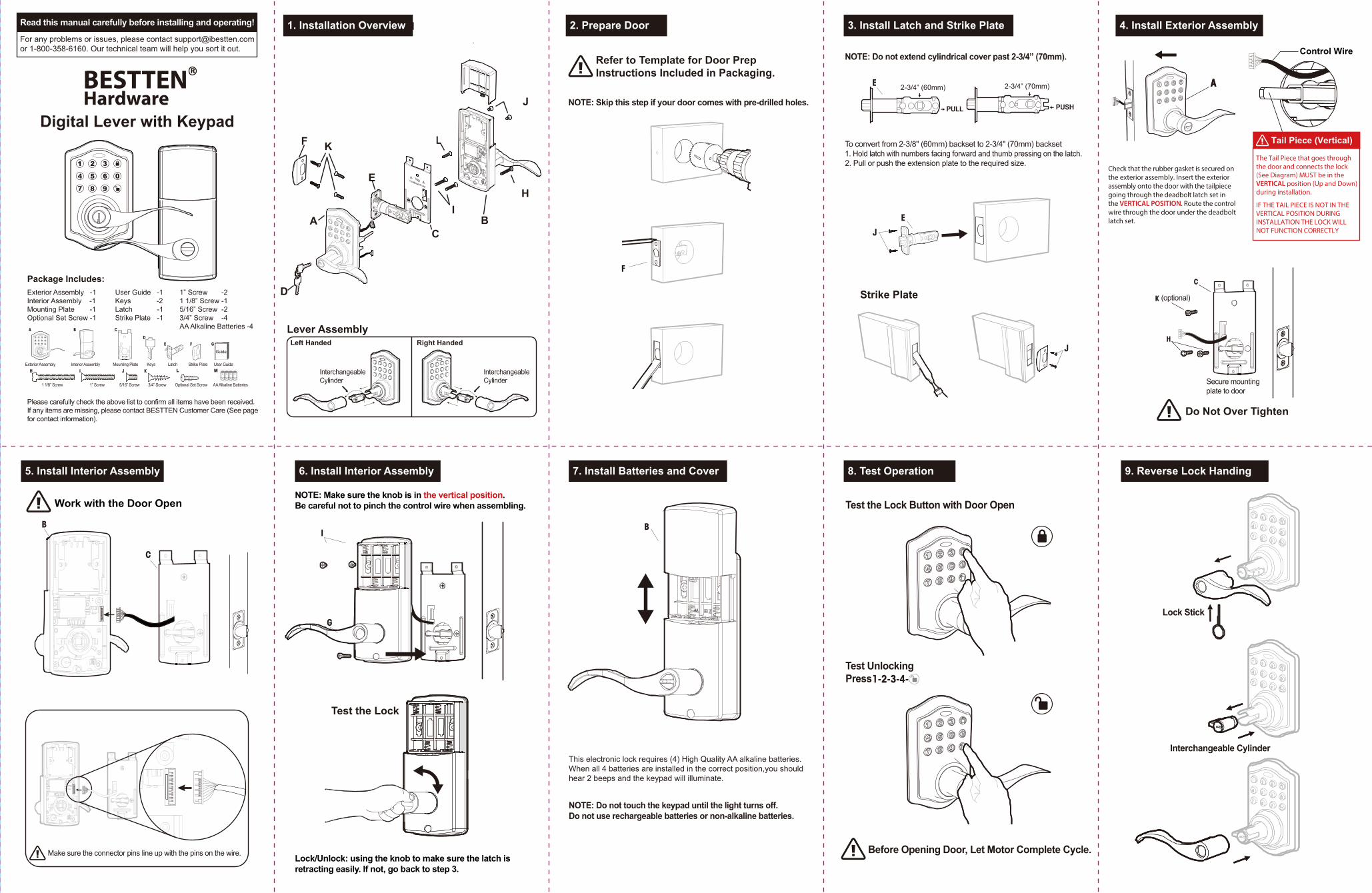
For any problems or issues, please contact [email protected] 1-800-358-6160. Our technical team will help you sort it out.
BESTTENR
HardwareDigital Lever with Keypad
Package Includes:Exterior Assembly -1Interior Assembly -1Mounting Plate -1Optional Set Screw -1
1” Screw -21 1/8” Screw -15/16” Screw -23/4” Screw -4AA Alkaline Batteries -4
Please carefully check the above list to confirm all items have been received. If any items are missing, please contact BESTTEN Customer Care (See page for contact information).
Guide
User Guide -1Keys -2Latch -1Strike Plate -1
Exterior Assembly Interior Assembly Keys Latch Strike Plate User GuideMounting Plate
1 1/8” Screw 1” Screw 5/16” Screw 3/4” Screw AA Alkaline BatteriesOptional Set Screw
Read this manual carefully before installing and operating!
L M
Lock/Unlock: using the knob to make sure the latch is retracting easily. If not, go back to step 3.
To convert from 2-3/8" (60mm) backset to 2-3/4" (70mm) backset1. Hold latch with numbers facing forward and thumb pressing on the latch.2. Pull or push the extension plate to the required size.
Strike Plate
Refer to Template for Door PrepInstructions Included in Packaging.
NOTE: Skip this step if your door comes with pre-drilled holes.
NOTE: Do not extend cylindrical cover past 2-3/4” (70mm).
2-3/4” (70mm)2-3/4” (60mm)
PULL PUSH
Secure mounting plate to door
Do Not Over Tighten
(optional)
5. Install Interior Assembly
4. Install Exterior Assembly1. Installation Overview 2. Prepare Door 3. Install Latch and Strike Plate
6. Install Interior Assembly 7. Install Batteries and Cover 8. Test Operation 9. Reverse Lock Handing
Work with the Door Open
Make sure the connector pins line up with the pins on the wire.
NOTE: Make sure the knob is in the vertical position.Be careful not to pinch the control wire when assembling.
Test the Lock
This electronic lock requires (4) High Quality AA alkaline batteries. When all 4 batteries are installed in the correct position,you should hear 2 beeps and the keypad will illuminate.
NOTE: Do not touch the keypad until the light turns off. Do not use rechargeable batteries or non-alkaline batteries.
Test the Lock Button with Door Open
Before Opening Door, Let Motor Complete Cycle.
Test Unlocking Press
H
Check that the rubber gasket is secured on the exterior assembly. Insert the exterior assembly onto the door with the tailpiece going through the deadbolt latch set in the VERTICAL POSITION. Route the control wire through the door under the deadbolt latch set.
Control Wire
Tail Piece (Vertical)
The Tail Piece that goes through the door and connects the lock (See Diagram) MUST be in the VERTICAL position (Up and Down) during installation.
IF THE TAIL PIECE IS NOT IN THE VERTICAL POSITION DURING INSTALLATION THE LOCK WILL NOT FUNCTION CORRECTLY
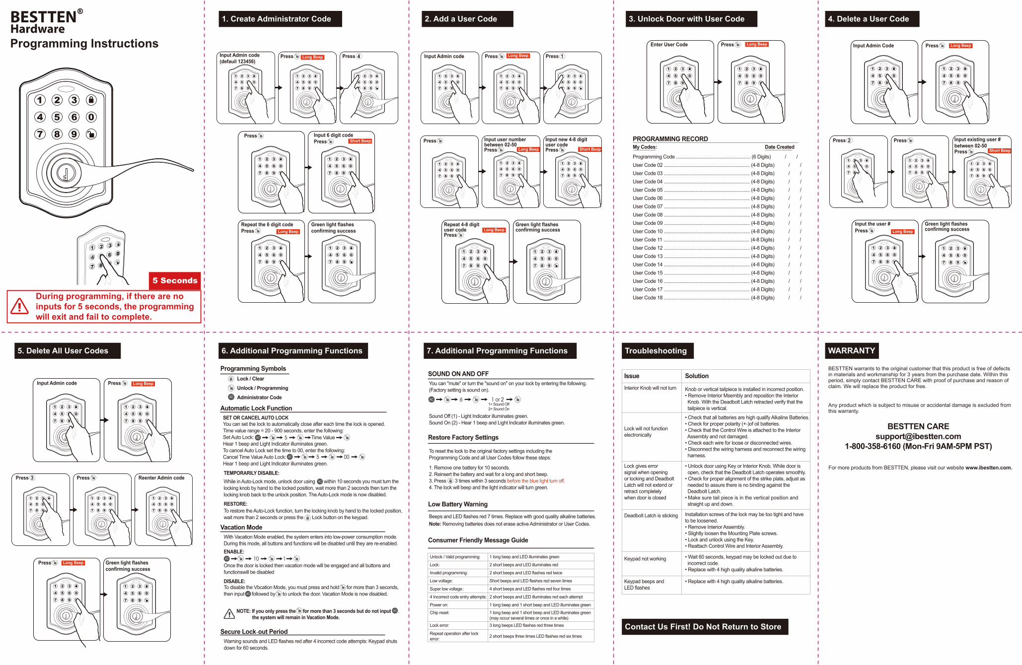
1. Remove one battery for 10 seconds.2. Reinsert the battery and wait for a long and short beep.3. Press 3 times within 3 seconds before the blue light turn off.4. The lock will beep and the light indicator will turn green.
Long Beep
Long Beep
Short Beep
Long Beep
Long Beep
Long Beep
Long Beep
Long Beep
Long Beep
Short Beep
Long Beep
Long Beep
Short Beep
Input Admin Code Press
Press Input existing user #between 02-50Press
Input the user #Press
Green light flashesconfirming success
Press 2
Enter User Code Press
Input Admin code
Input new 4-8 digituser code
Press
Press Input user number between 02-50Press
Repeat 4-8 digit user codePress
Green light flashesconfirming success
Press
Press 1Input Admin code(defauil 123456)
Press
Press Input 6 digit codePress
Repeat the 6 digit codePress
Green light flashesconfirming success
Press 4
Input Admin code
Reenter Admin code
Press
Press
Press Green light flashesconfirming success
Press 3
IssueInterior Knob will not turn
Solution
• Check that all batteries are high qualify Alkaline Batteries.• Check for proper polarity (+-)of oil batteries.• Check that the Control Wire is attached to the Interior Assembly and not damaged.• Check each wire for loose or disconnected wires.• Disconnect the wiring harness and reconnect the wiring harness.
• Unlock door using Key or Interior Knob. While door is open, check that the Deadbolt Latch operates smoothly.• Check for proper alignment of the strike plate, adjust as needed to assure there is no binding against the Deadbolt Latch.• Make sure tail piece is in the vertical position and straight up and down.
Installation screws of the lock may be too tight and have to be loosened.• Remove Interior Assembly.• Slightly loosen the Mounting Plate screws.• Lock and unlock using the Key.• Reattach Control Wire and Interior Assembly.
• Wait 60 seconds, keypad may be locked out due to incorrect code.• Replace with 4 high quality alkaline batteries.
• Replace with 4 high quality alkaline batteries.
Lock will not functionelectronically
Deadbolt Latch is sticking
Keypad not working
Keypad beeps and LED flashes
Lock gives error signal when opening or locking and Deadbolt Latch will not extend or retract completely when door is closed
Knob or vertical tailpiece is installed in incorrect position.• Remove Interior Msembly and reposition the Interior Knob. With the Deadbolt Latch retracted verify that the tailpiece is vertical.
Sound Off (1) - Light Indicator illuminates green.Sound On (2) - Hear 1 beep and Light Indicator illuminates green.
Programming Code .......................................................... (6 Digits) / /User Code 02 ................................................................... (4-8 Digits) / /User Code 03 ................................................................... (4-8 Digits) / / User Code 04 ................................................................... (4-8 Digits) / /User Code 05 ................................................................... (4-8 Digits) / /User Code 06 ................................................................... (4-8 Digits) / /User Code 07 ................................................................... (4-8 Digits) / /User Code 08 ................................................................... (4-8 Digits) / /User Code 09 ................................................................... (4-8 Digits) / /User Code 10 ................................................................... (4-8 Digits) / /User Code 11 ................................................................... (4-8 Digits) / /User Code 12 ................................................................... (4-8 Digits) / /User Code 13 ................................................................... (4-8 Digits) / /User Code 14 ................................................................... (4-8 Digits) / /User Code 15 ................................................................... (4-8 Digits) / /User Code 16 ................................................................... (4-8 Digits) / /User Code 17 ................................................................... (4-8 Digits) / /User Code 18 ................................................................... (4-8 Digits) / /
1. Create Administrator Code 2. Add a User Code 3. Unlock Door with User Code 4. Delete a User Code
5. Delete All User Codes 6. Additional Programming Functions 7. Additional Programming Functions Troubleshooting
Contact Us First! Do Not Return to Store
PROGRAMMING RECORDMy Codes: Date Created
Lock / Clear
Programming Symbols
Automatic Lock Function
Vacation Mode
TEMPORARILY DISABLE:
RESTORE:
SET OR CANCEL AUTO LOCK
Unlock / ProgrammingAdministrator Code
You can set the lock to automatically close after each time the lock is opened. Time value range = 20 - 900 seconds, enter the following: Set Auto Lock: Hear 1 beep and Light Indicator illuminates green. To cancel Auto Lock set the time to 00, enter the following: Cancel Time Value Auto Lock: Hear 1 beep and Light Indicator illuminates green.
Time Value
While in Auto-Lock mode, unlock door using within 10 seconds you must turn the locking knob by hand to the locked position, wait more than 2 seconds then turn the locking knob back to the unlock position. The Auto-Lock mode is now disabled.
To restore the Auto-Lock function, turn the locking knob by hand to the locked position, wait more than 2 seconds or press the Lock button on the keypad.
With Vacation Mode enabled, the system enters into low-power consumption mode. During this mode, all buttons and functions will be disabled until they are re-enabled.ENABLE:
Once the door is locked then vacation mode will be engaged and all buttons and functionswill be disabled
DISABLE:To disable the Vbcation Mode, you must press and hold for more than 3 seconds, then input followed by to unlock the door. Vacation Mode is now disabled.
NOTE: If you only press the for more than 3 seconds but do not input , the system will remain in Vacation Mode.
Secure Lock-out PeriodWarning sounds and LED flashes red after 4 incorrect code attempts: Keypad shuts down for 60 seconds.
SOUND ON AND OFF
Restore Factory Settings
Low Battery Warning
You can "mute" or turn the "sound on" on your lock by entering the following. (Factory setting is sound on).
1= Sound Off2= Sound On
To reset the lock to the original factory settings including theProgramming Code and all User Codes follow these steps:
Beeps and LED flashes red 7 times. Replace with good quality alkaline batteries.Note: Removing batteries does not erase active Administrator or User Codes.
Consumer Friendly Message Guide
Unlock / Valid programming:
Lock:
Invalid programming:
Low voltage:
1 long beep and LED illuminates green
2 short beeps and LED illuminates red
2 short beeps and LED flashes red twice
Short beeps and LED flashes red seven times
4 short beeps and LED flashes red four times
2 short beeps and LED illuminates red each attempt
1 long beep and 1 short beep and LED illuminates green1 long beep and 1 short beep and LED illuminates green (may occur several times or once in a while)3 long beeps LED flashes red three times
2 short beeps three times LED flashes red six times
Super low voltage:
4 Incorrect code entry attempts:
Power on:Chip reset:
Lock error:
Repeat operation after lock error:
WARRANTY
Any product which is subject to misuse or accidental damage is excluded from this warranty.
BESTTEN [email protected]
1-800-358-6160 (Mon-Fri 9AM-5PM PST)
For more products from BESTTEN, please visit our website www.ibestten.com.
BESTTENR
HardwareProgramming Instructions
BESTTEN warrants to the original customer that this product is free of defects in materials and workmanship for 3 years from the purchase date. Within this period, simply contact BESTTEN CARE with proof of purchase and reason of claim. We will replace the product for free.
During programming, if there are no inputs for 5 seconds, the programming will exit and fail to complete.
5 Seconds