Embed Size (px)
Citation preview
IBC controlMade in Sweden
MANUAL
CONTROL UNIT FOR ROTATING HEAT EXCHANGER
MicroMaxArticle no. F21009201

Installation instructions 2
Mounting 2
Safety instructions 3
Manufacturer's declaration 4
Description of functions 5
Technical data 6
Functions 6
- DIP switch 7
- Operational indications 7
- Alarms 8-9
- Settings via potentiometer 9
- Push button 9
Connection diagram 10
Connections 10
Checks before powering up the control unit
11
Putting the equipment into operation
11
EMC installation 12
EMC gland 12
Personal notes 13
TABLE OF CONTENTS
Warning indication The control unit may only be used in perfect technical condition.Any damage that may affect safety must be dealt with immedi-ately.
Maintenance/Repairs The function of the control unit should be checked regularly.Troubleshooting and repairs may only be performed by trained personnel.Electrical safety regulations must be met.
Disposal and recycling When replacing components or when the control unit in its entirety need replacing, please follow the advice below:The aim should always be maximum possible recycling of raw materials, with minimum possible environmental impact.Never dispose of electrical components with ordinary waste, always use the designated collection points.Disposal should be as environment-friendly as the technology allows in terms of environmental protection and recycling.
INSTALLATION INSTRUCTIONS
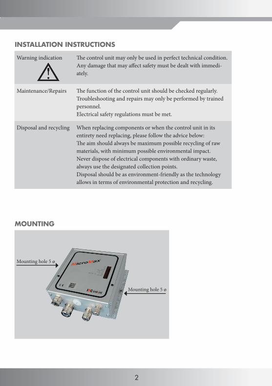
MOUNTING
Mounting hole 5 ø
Mounting hole 5 ø
2
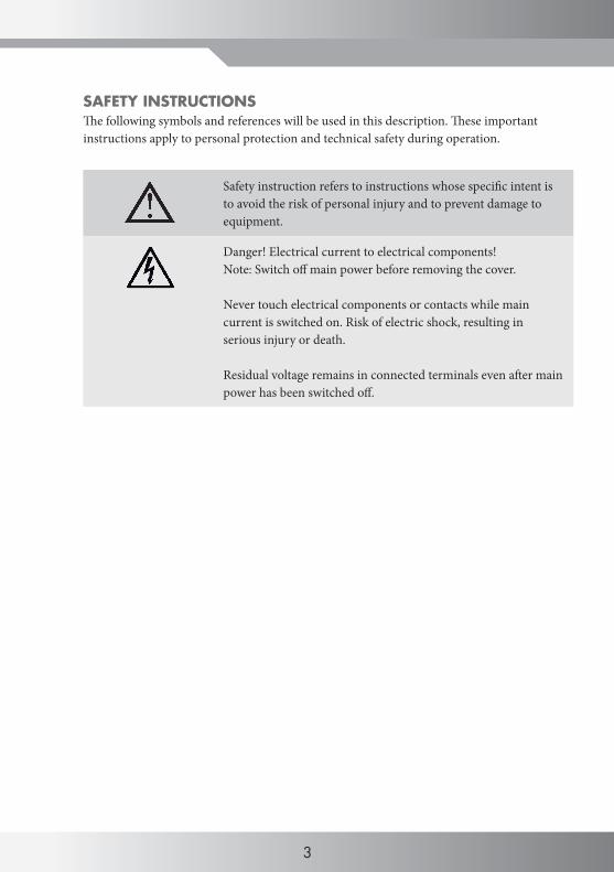
SAFETY INSTRUCTIONS
Safety instruction refers to instructions whose specific intent is to avoid the risk of personal injury and to prevent damage to equipment.
Danger! Electrical current to electrical components!Note: Switch off main power before removing the cover.
Never touch electrical components or contacts while main current is switched on. Risk of electric shock, resulting in serious injury or death.
Residual voltage remains in connected terminals even after main power has been switched off.
The following symbols and references will be used in this description. These important instructions apply to personal protection and technical safety during operation.
2 3
4
MANUFACTURER'S DECLARATION
Manufacturer IBC control ABBrännerigatan 5 A, SE-263 37 Höganäs, Sweden
Product Control unit for rotating heat exchanger
Type designation MicroMax
Article number F21009201
EU directive applied to the product
The manufacturer's declaration of conformity with the requirements of the EMC Directive 2004/108/EC.
All control units are approved according to the requirements of the EMC Directive 2004/108/EC and are tested according to standard EN 61800-3:2004, emission category C1 and immunity category C2.
All control units comply with the Low Voltage Directive 2006/95/EC, standard EN 61800-5-1.
All control units are designed for installation in environments subject to pollution degree 2.
This product also complies with RoHS Directive 2011/65/EU.
Höganäs 2015-07-01 IBC control AB
Christer Persson MD
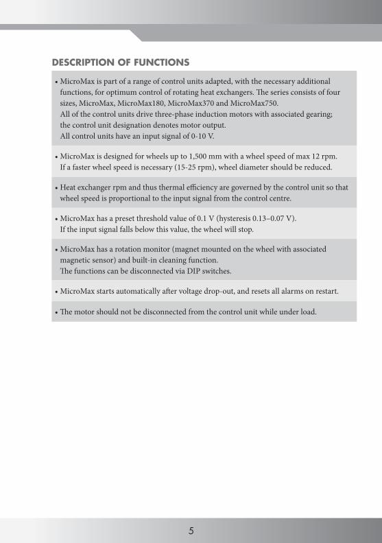
•MicroMax is part of a range of control units adapted, with the necessary additional functions, for optimum control of rotating heat exchangers. The series consists of four sizes, MicroMax, MicroMax180, MicroMax370 and MicroMax750. All of the control units drive three-phase induction motors with associated gearing; the control unit designation denotes motor output. All control units have an input signal of 0-10 V.
•MicroMax is designed for wheels up to 1,500 mm with a wheel speed of max 12 rpm. If a faster wheel speed is necessary (15-25 rpm), wheel diameter should be reduced.
•Heat exchanger rpm and thus thermal efficiency are governed by the control unit so that wheel speed is proportional to the input signal from the control centre.
•MicroMax has a preset threshold value of 0.1 V (hysteresis 0.13–0.07 V). If the input signal falls below this value, the wheel will stop.
•MicroMax has a rotation monitor (magnet mounted on the wheel with associated magnetic sensor) and built-in cleaning function. The functions can be disconnected via DIP switches.
•MicroMax starts automatically after voltage drop-out, and resets all alarms on restart.
•The motor should not be disconnected from the control unit while under load.
DESCRIPTION OF FUNCTIONS
4 5
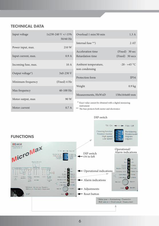
Overload 1 min/30 min 1.3 A
Internal fuse **) 2 AT
Acceleration timeRetardation time
(Fixed) 30 sec(Fixed) 30 secs
Ambient temperature, non condensing
-20 - +45 OC
Protection form IP54
Weight 0.9 kg
Measurements, HxWxD 158x164x60 mm
Input voltage 1x230-240 V +/-15%50/60 Hz
Power input, max. 210 W
Input current, max. 0.9 A
Incoming fuse, max. 10 A
Output voltage*) 3x0-230 V
Minimum frequency (Fixed) 4 Hz
Max frequency 40-100 Hz
Motor output, max 90 W
Motor current 0.7 A
* Exact value cannot be obtained with a digital measuring instrument ** The fuse protects both motor and electronics
Reset button
DIP switchON to left
Adjustments
TECHNICAL DATA
FUNCTIONS
4 1 2 35
DIP switch
Operational/ Alarm indications
6
Operational indications
Alarm indications
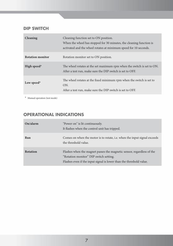
DIP SWITCH
Cleaning Cleaning function set to ON position.When the wheel has stopped for 30 minutes, the cleaning function is activated and the wheel rotates at minimum speed for 10 seconds.
Rotation monitor Rotation monitor set to ON position.
High speed* The wheel rotates at the set maximum rpm when the switch is set to ON.After a test run, make sure the DIP switch is set to OFF.
Low speed*The wheel rotates at the fixed minimum rpm when the switch is set to ON.After a test run, make sure the DIP switch is set to OFF.
* Manual operation (test mode)
OPERATIONAL INDICATIONS
On/alarm "Power on" is lit continuously. It flashes when the control unit has tripped.
Run Comes on when the motor is to rotate, i.e. when the input signal exceeds the threshold value.
Rotation Flashes when the magnet passes the magnetic sensor, regardless of the “Rotation monitor” DIP switch setting. Flashes even if the input signal is lower than the threshold value.
6 7
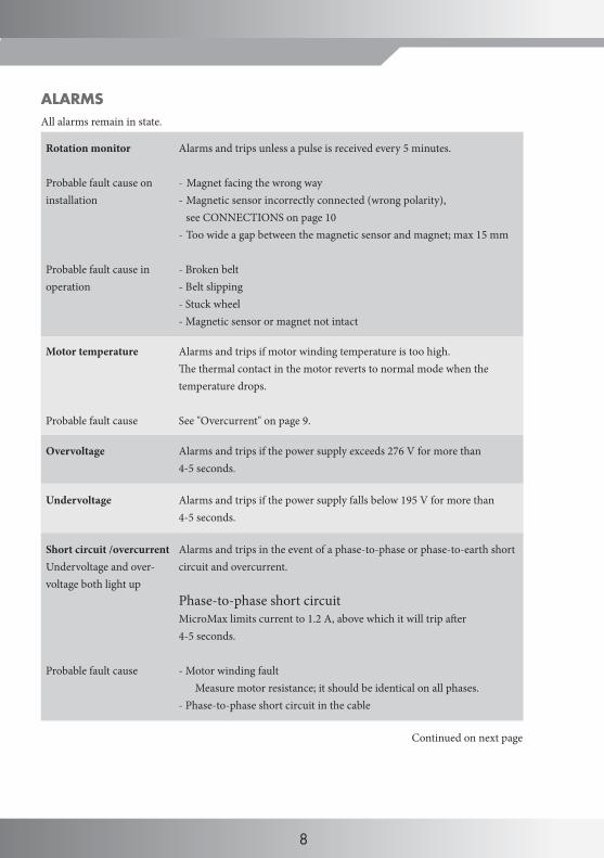
Rotation monitor
Probable fault cause on installation
Probable fault cause in operation
Alarms and trips unless a pulse is received every 5 minutes.
- Magnet facing the wrong way- Magnetic sensor incorrectly connected (wrong polarity), see CONNECTIONS on page 10- Too wide a gap between the magnetic sensor and magnet; max 15 mm
- Broken belt- Belt slipping- Stuck wheel- Magnetic sensor or magnet not intact
Motor temperature
Probable fault cause
Alarms and trips if motor winding temperature is too high.The thermal contact in the motor reverts to normal mode when the temperature drops.
See "Overcurrent" on page 9.
Overvoltage Alarms and trips if the power supply exceeds 276 V for more than 4-5 seconds.
Undervoltage Alarms and trips if the power supply falls below 195 V for more than 4-5 seconds.
Short circuit /overcurrentUndervoltage and over-voltage both light up
Probable fault cause
Alarms and trips in the event of a phase-to-phase or phase-to-earth short circuit and overcurrent.
Phase-to-phase short circuitMicroMax limits current to 1.2 A, above which it will trip after 4-5 seconds.
- Motor winding faultMeasure motor resistance; it should be identical on all phases.
- Phase-to-phase short circuit in the cable
ALARMS All alarms remain in state.
Continued on next page
8
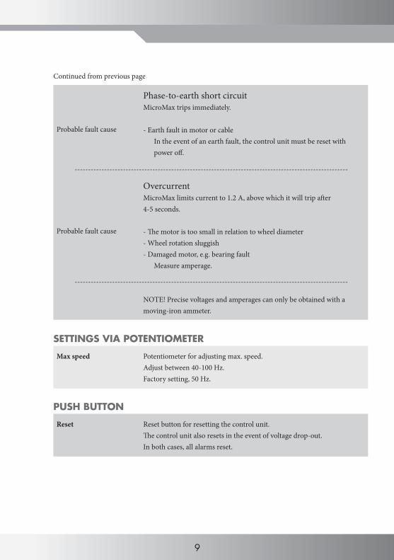
Continued from previous page
Probable fault cause
Probable fault cause
Phase-to-earth short circuitMicroMax trips immediately.
- Earth fault in motor or cable In the event of an earth fault, the control unit must be reset with power off.
OvercurrentMicroMax limits current to 1.2 A, above which it will trip after 4-5 seconds.
- The motor is too small in relation to wheel diameter- Wheel rotation sluggish- Damaged motor, e.g. bearing fault
Measure amperage.
NOTE! Precise voltages and amperages can only be obtained with a moving-iron ammeter.
------------------------------------------------------------------------------------------------------
SETTINGS VIA POTENTIOMETER
Max speed Potentiometer for adjusting max. speed.Adjust between 40-100 Hz. Factory setting, 50 Hz.
PUSH BUTTON
Reset Reset button for resetting the control unit. The control unit also resets in the event of voltage drop-out. In both cases, all alarms reset.
------------------------------------------------------------------------------------------------------
8 9
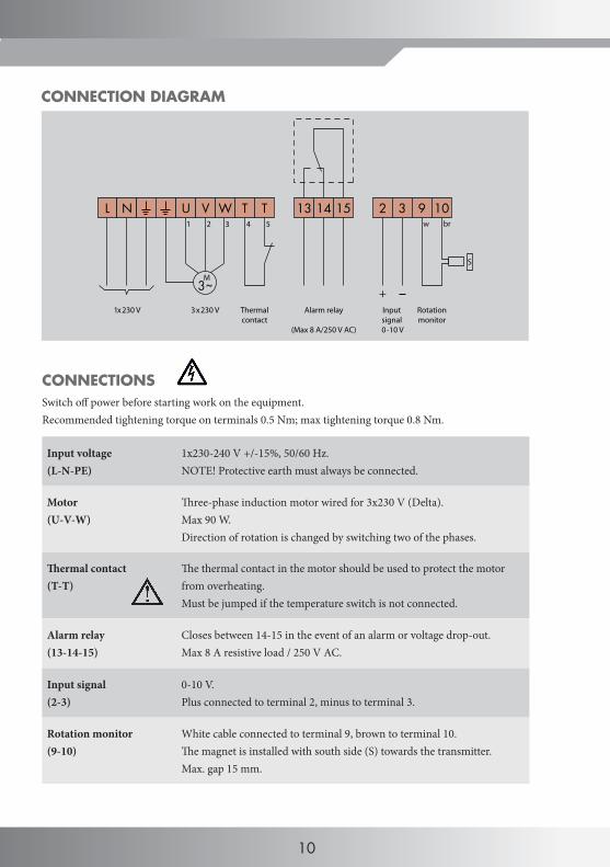
CONNECTIONSSwitch off power before starting work on the equipment.Recommended tightening torque on terminals 0.5 Nm; max tightening torque 0.8 Nm.
Input voltage(L-N-PE)
1x230-240 V +/-15%, 50/60 Hz.NOTE! Protective earth must always be connected.
Motor(U-V-W)
Three-phase induction motor wired for 3x230 V (Delta).Max 90 W.Direction of rotation is changed by switching two of the phases.
Thermal contact (T-T)
The thermal contact in the motor should be used to protect the motor from overheating.Must be jumped if the temperature switch is not connected.
Alarm relay(13-14-15)
Closes between 14-15 in the event of an alarm or voltage drop-out.Max 8 A resistive load / 250 V AC.
Input signal(2-3)
0-10 V. Plus connected to terminal 2, minus to terminal 3.
Rotation monitor(9-10)
White cable connected to terminal 9, brown to terminal 10.The magnet is installed with south side (S) towards the transmitter.Max. gap 15 mm.
CONNECTION DIAGRAM
10
T T 2 3
+Input signal 0-10 V
9 10 w
Rotationmonitor
3~
L N U V W
M
1x230 V 3x230 V Thermalcontact
13 14 15
Alarm relay
(Max 8 A/250 V AC)
S
21 3 4 5 br
10
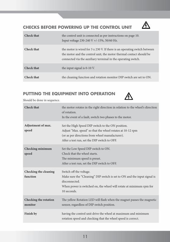
Check that the control unit is connected as per instructions on page 10.Input voltage 230-240 V +/-15%, 50/60 Hz.
Check that the motor is wired for 3 x 230 V. If there is an operating switch between the motor and the control unit, the motor thermal contact should be connected via the auxiliary terminal in the operating switch.
Check that the input signal is 0-10 V.
Check that the cleaning function and rotation monitor DIP switch are set to ON.
PUTTING THE EQUIPMENT INTO OPERATION
Should be done in sequence.
Check that the motor rotates in the right direction in relation to the wheel's direction of rotation. In the event of a fault, switch two phases to the motor.
Adjustment of max. speed
Set the High Speed DIP switch to the ON position. Adjust "Max. speed" so that the wheel rotates at 10-12 rpm (or as per directions from wheel manufacturer). After a test run, set the DIP switch to OFF.
Checking minimum speed
Set the Low Speed DIP switch to ON. Check that the wheel starts. The minimum speed is preset. After a test run, set the DIP switch to OFF.
Checking the cleaning function
Switch off the voltage.Make sure the “Cleaning” DIP switch is set to ON and the input signal is disconnected. When power is switched on, the wheel will rotate at minimum rpm for 10 seconds.
Checking the rotation monitor
The yellow Rotation LED will flash when the magnet passes the magnetic sensor, regardless of DIP switch position.
Finish by having the control unit drive the wheel at maximum and minimum rotation speed and checking that the wheel speed is correct.
CHECKS BEFORE POWERING UP THE CONTROL UNIT
11
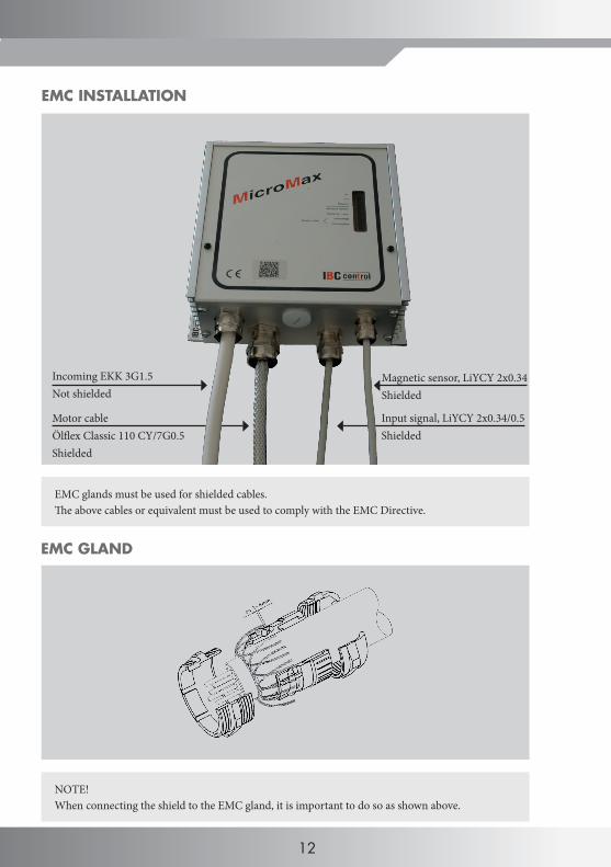
Magnetic sensor, LiYCY 2x0.34Shielded
Input signal, LiYCY 2x0.34/0.5Shielded
EMC INSTALLATION
EMC GLAND
Motor cableÖlflex Classic 110 CY/7G0.5Shielded
Incoming EKK 3G1.5Not shielded
EMC glands must be used for shielded cables. The above cables or equivalent must be used to comply with the EMC Directive.
NOTE!When connecting the shield to the EMC gland, it is important to do so as shown above.
12

YOUR NOTES
12 13
IBC control ABBrännerigatan 5 ASE-263 37 HöganäsSwedenTel. +46 (0)42-33 00 10Fax +46 (0)42-33 03 [email protected]
IBC control
F210
7590
1Ve
rsio
n 2.
020
15-0
7-01