Embed Size (px)
Citation preview
Chapter 6
Control Technology of Solidification and Cooling in theProcess of Continuous Casting of Steel
Qing Liu, Xiaofeng Zhang, Bin Wang andBao Wang
Additional information is available at the end of the chapter
http://dx.doi.org/10.5772/51457
1. Introduction
Solidification and cooling control, which is a key technology in the continuous casting proc‐ess, has a quick development in recent years, and meet the modern requirements of the con‐tinuous casting process on the whole. However, the control models and cooling technologyneed constant development and improvement due to the trend toward delicacy and full au‐tomation in continuous casting. This chapter discusses the hot ductility, the thermophysicalproperties, the solidification and cooling control models and nozzles layouts for secondarycooling, besides these, the planning for the process of steelmaking-rolling, which are closelyrelated with solidification and cooling in continuous casting process.
2. Research on the thermal physical parameters of steels
This section summarizes formulae for calculating thermal physical parameters of steel slabs,including the liquidus temperature, solidus temperature, thermal conductivity, and so on.The database of thermal physical parameters including thermoplastic was specially estab‐lished and embedded in the control model of the solidification and cooling, which is con‐venient to query data and update operation for technical staffs. Moreover, based on thethermoplastic parameter database, the target surface control temperature of slab is deter‐mined for the production of various grades of steels. And the database is helpful for users toacquire more accurate results of the heat transfer model.
© 2012 Liu et al.; licensee InTech. This is an open access article distributed under the terms of the CreativeCommons Attribution License (http://creativecommons.org/licenses/by/3.0), which permits unrestricted use,distribution, and reproduction in any medium, provided the original work is properly cited.
2.1. Research on thermoplastic of steels
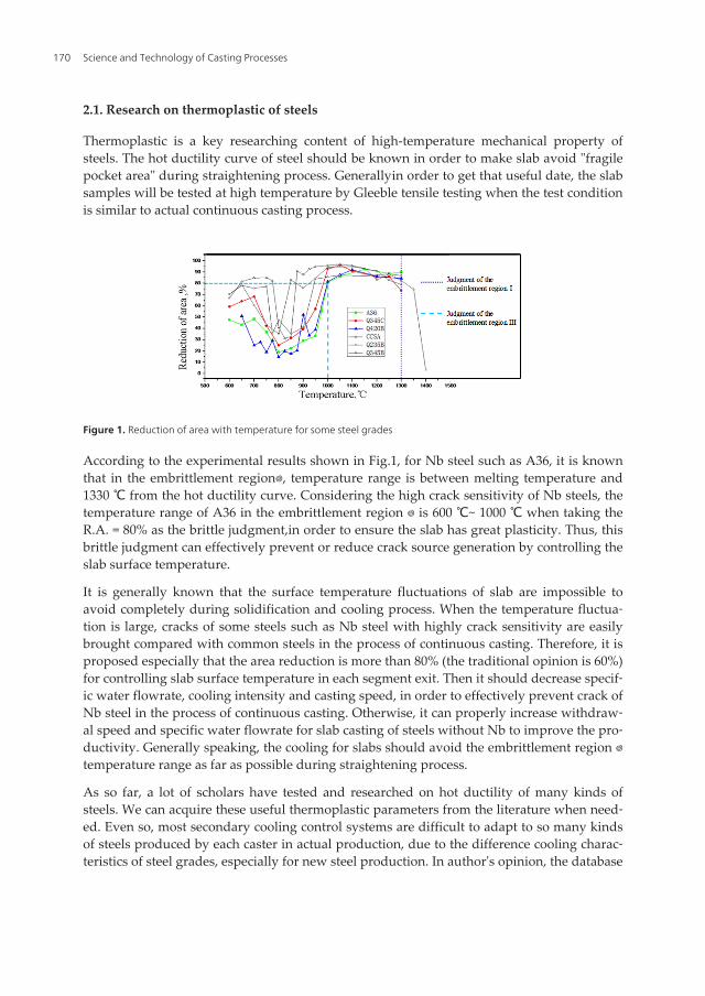
Thermoplastic is a key researching content of high-temperature mechanical property ofsteels. The hot ductility curve of steel should be known in order to make slab avoid "fragilepocket area" during straightening process. Generally�in order to get that useful date, the slabsamples will be tested at high temperature by Gleeble tensile testing when the test conditionis similar to actual continuous casting process.
Figure 1. Reduction of area with temperature for some steel grades
According to the experimental results shown in Fig.1, for Nb steel such as A36, it is knownthat in the embrittlement regionⅠ, temperature range is between melting temperature and1330 ℃ from the hot ductility curve. Considering the high crack sensitivity of Nb steels, thetemperature range of A36 in the embrittlement region Ⅰ is 600 ℃~ 1000 ℃ when taking theR.A. = 80% as the brittle judgment,in order to ensure the slab has great plasticity. Thus, thisbrittle judgment can effectively prevent or reduce crack source generation by controlling theslab surface temperature.
It is generally known that the surface temperature fluctuations of slab are impossible toavoid completely during solidification and cooling process. When the temperature fluctua‐tion is large, cracks of some steels such as Nb steel with highly crack sensitivity are easilybrought compared with common steels in the process of continuous casting. Therefore, it isproposed especially that the area reduction is more than 80% (the traditional opinion is 60%)for controlling slab surface temperature in each segment exit. Then it should decrease specif‐ic water flowrate, cooling intensity and casting speed, in order to effectively prevent crack ofNb steel in the process of continuous casting. Otherwise, it can properly increase withdraw‐al speed and specific water flowrate for slab casting of steels without Nb to improve the pro‐ductivity. Generally speaking, the cooling for slabs should avoid the embrittlement region Ⅰtemperature range as far as possible during straightening process.
As so far, a lot of scholars have tested and researched on hot ductility of many kinds ofsteels. We can acquire these useful thermoplastic parameters from the literature when need‐ed. Even so, most secondary cooling control systems are difficult to adapt to so many kindsof steels produced by each caster in actual production, due to the difference cooling charac‐teristics of steel grades, especially for new steel production. In author's opinion, the database
Science and Technology of Casting Processes170
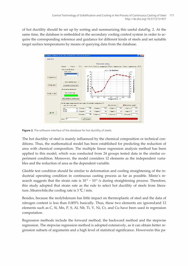
of hot ductility should be set up by sorting and summarizing this useful data�Fig. 2�. At thesame time, the database is embedded in the secondary cooling control system in order to ac‐quire the corresponding reference and guidance for different kinds of steels and set suitabletarget surface temperatures by means of querying data from the database.
Figure 2. The software interface of the database for hot ductility of steels
The hot ductility of steel is mainly influenced by the chemical composition or technical con‐ditions. Thus, the mathematical model has been established for predicting the reduction ofarea with chemical composition. The multiple linear regression analysis method has beenapplied to this model, which was conducted from 24 groups tested data in the similar ex‐periment condition. Moreover, the model considers 12 elements as the independent varia‐bles and the reduction of area as the dependent variable.
Gleeble test condition should be similar to deformation and cooling straightening of the in‐dustrial operating condition in continuous casting process as far as possible. Mintz’s re‐search suggests that the strain rate is 10-3 ~ 10-4 /s during straightening process. Therefore,this study adopted that strain rate as the rule to select hot ductility of steels from litera‐ture..Meanwhile,the cooling rate is 3 ℃ / min.
Besides, because the molybdenum has little impact on thermoplastic of steel and the data ofnitrogen content is less than 0.005% basically. Thus, these two elements are ignored�and 12elements such as C, Si, Mn, P, S, Al, Nb, Ti, V, Ni, Cr, and Cu have been used in regressioncomputation.
Regression methods include the forward method, the backward method and the stepwiseregression. The stepwise regression method is adopted extensively, as it can obtain better re‐gression subsets of arguments and a high level of statistical significance. However�in this pa‐
Control Technology of Solidification and Cooling in the Process of Continuous Casting of Steelhttp://dx.doi.org/10.5772/51457
171
per, the backward method is selected in order to make the regression reflects the influenceof the elements as accurate as possible.
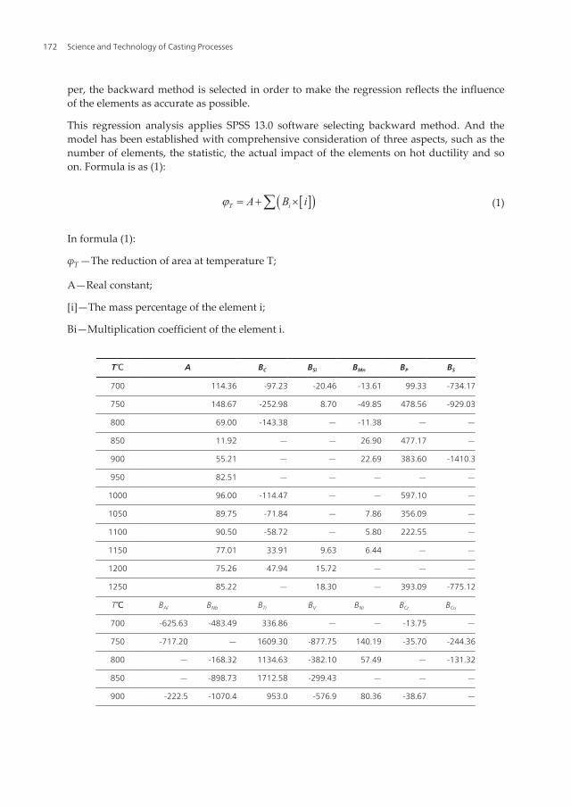
This regression analysis applies SPSS 13.0 software selecting backward method. And themodel has been established with comprehensive consideration of three aspects, such as thenumber of elements, the statistic, the actual impact of the elements on hot ductility and soon. Formula is as (1):
[ ]( )T iA B ij = + ´å (1)
In formula (1):
φT—The reduction of area at temperature T;
A—Real constant;
[i]—The mass percentage of the element i;
Bi—Multiplication coefficient of the element i.
T�℃ A BC BSi BMn BP BS
700 114.36 -97.23 -20.46 -13.61 99.33 -734.17
750 148.67 -252.98 8.70 -49.85 478.56 -929.03
800 69.00 -143.38 — -11.38 — —
850 11.92 — — 26.90 477.17 —
900 55.21 — — 22.69 383.60 -1410.3
950 82.51 — — — — —
1000 96.00 -114.47 — — 597.10 —
1050 89.75 -71.84 — 7.86 356.09 —
1100 90.50 -58.72 — 5.80 222.55 —
1150 77.01 33.91 9.63 6.44 — —
1200 75.26 47.94 15.72 — — —
1250 85.22 — 18.30 — 393.09 -775.12
T�℃ BAl BNb BTi BV BNi BCr BCu
700 -625.63 -483.49 336.86 — — -13.75 —
750 -717.20 — 1609.30 -877.75 140.19 -35.70 -244.36
800 — -168.32 1134.63 -382.10 57.49 — -131.32
850 — -898.73 1712.58 -299.43 — — —
900 -222.5 -1070.4 953.0 -576.9 80.36 -38.67 —
Science and Technology of Casting Processes172
T�℃ A BC BSi BMn BP BS
950 -251.49 -835.70 1317.37 -360.55 183.88 -41.38 —
1000 — -447.60 732.06 -161.26 403.80 -88.33 -282.22
1050 — -441.53 290.78 -91.64 274.55 -68.82 -162.25
1100 114.88 -362.14 — — 200.44 -44.85 -136.52
1150 77.20 -418.90 405.60 — 76.43 -29.22 —
1200 — -49.51 — 59.79 -42.96 — 51.38
1250 -143.42 -73.51 — — 75.94 -35.42 -86.62
Table 1. A, Bi values of formula (2)
The accuracy of regression model needs significant tests. Several important significant teststatistics indexes of the regression model are as follows�
F: F inspection value; the bigger the F value, the better the significance level is.
R2�Multiple correlation coefficients�reflect regression effect quality: the greater the R2, the bet‐ter the regression result is. Generally, R2 equaling to 0.7 or so can give a positive attitude.
Ra2: Multiple correlation coefficients after adjustment. Formula is as (2):
( )2 211 11a
nR Rn p
-= - -
- -(2)
Sig: Significant level value; the smaller value, the better result is.
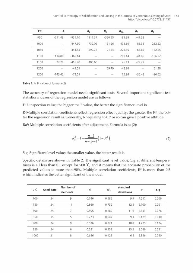
Specific details are shown in Table 2. The significant level value, Sig at different tempera‐tures is all less than 0.1 except for 900 ℃, and it means that the accurate probability of thepredicted values is more than 90%. Multiple correlation coefficients, R2 is more than 0.5�which indicates the better significant of the model.
T�℃ Used dateNumber of
elementsR2 R2
a
standard
deviationsF Sig
700 24 9 0.746 0.582 9.9 4.557 0.006
750 24 11 0.860 0.732 12.5 6.700 0.001
800 24 7 0.505 0.289 11.6 2.333 0.076
850 15 5 0.773 0.647 9.1 6.129 0.010
900 24 9 0.526 0.221 18.8 1.725 0.174
950 24 6 0.521 0.352 15.5 3.086 0.031
1000 21 8 0.656 0.426 6.5 2.856 0.050
Control Technology of Solidification and Cooling in the Process of Continuous Casting of Steelhttp://dx.doi.org/10.5772/51457
173
T�℃ Used dateNumber of
elementsR2 R2
a
standard
deviationsF Sig
1050 21 9 0.739 0.526 4.4 3.163 0.028
1100 21 8 0.660 0.433 4.2 2.913 0.047
1150 21 8 0.698 0.497 3.4 3.467 0.026
1200 21 6 0.688 0.554 2.8 5.140 0.006
1250 21 8 0.724 0.540 4.1 3.936 0.017
Table 2. Statistics in significant test of regression model
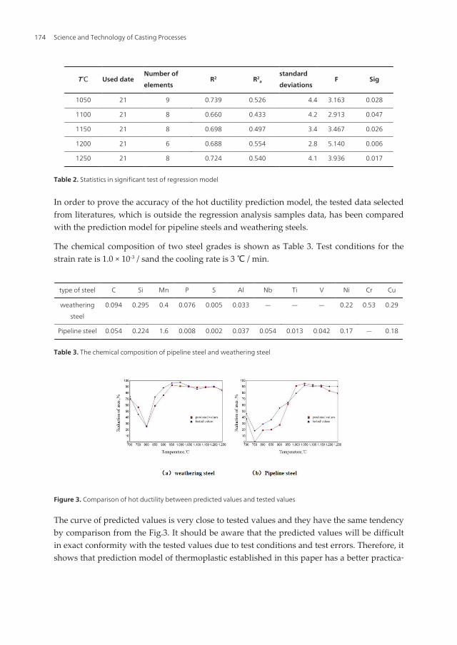
In order to prove the accuracy of the hot ductility prediction model, the tested data selectedfrom literatures, which is outside the regression analysis samples data, has been comparedwith the prediction model for pipeline steels and weathering steels.
The chemical composition of two steel grades is shown as Table 3. Test conditions for thestrain rate is 1.0 × 10⁻³ / s�and the cooling rate is 3 ℃ / min.
type of steel C Si Mn P S Al Nb Ti V Ni Cr Cu
weathering
steel
0.094 0.295 0.4 0.076 0.005 0.033 — — — 0.22 0.53 0.29
Pipeline steel 0.054 0.224 1.6 0.008 0.002 0.037 0.054 0.013 0.042 0.17 — 0.18
Table 3. The chemical composition of pipeline steel and weathering steel
Figure 3. Comparison of hot ductility between predicted values and tested values
The curve of predicted values is very close to tested values and they have the same tendencyby comparison from the Fig.3. It should be aware that the predicted values will be difficultin exact conformity with the tested values due to test conditions and test errors. Therefore, itshows that prediction model of thermoplastic established in this paper has a better practica‐
Science and Technology of Casting Processes174
bility. Even so, the model has some limitations because of less regression sample data of on‐ly 24 groups. But with more studies on hot ductility, the model will evolve further.
2.2. Formulae for thermal physical parameters
The thermophysical property parameters of steel such as density, conductivity coefficient,specific heat capacity, latent heat, liquidus temperature, and solidus temperature are essen‐tial for calculating the heat transfer model. Although these parameters can only be acquiredaccurately by tests, the thermophysical properties of a new steel grade can also be approxi‐mately calculated from the chemical composition with the requirements of more steel gradesto cast.
2.2.1. Liquidus temperature
The liquidus temperature of steel plays a very important role in metallurgical productionand related scientific research. The lowest superheat may be achieved during the process ofcontinuous casting if an accurate liquidus temperature of steel is obtained. This is describedas it is useful to acquire a fine grain structure and higher quality of slab for steel plants. Theaccurate liquidus temperature of steel is also required for scientific investigation of solidifi‐cation processes of molten steel by numerical simulation. Research shows that the main rea‐son why the liquidus temperature of steel is lower than the melting point of pure iron is thepresence of impurities and alloying elements. Generally speaking, there are two ways to ob‐tain the liquidus temperature of steel for the research: firstly, as a standard method for de‐termining transformation temperature of materials, a differential thermal analysis (DTA)measurements is conducted, and a number of studies have used DTA for the determinationof liquidus temperature; secondly, the more common method, is to select the appropriatemodel according to the different kinds of steel. On the basis of the analysis of Fe-i binaryphase diagram, a new calculation model for liquidus temperature of steel is established inthis study.
The different effects of 11 elements (C, Si, Mn, P, S, Ca, Nb, Ni, Cu, Mo,Cr) on the meltingpoint of pure iron were investigated and 11 groups of discrete data (AC, ASi... ACr)�that is�thevalue of liquidus temperature was decreased or increased together with the content of ele‐ment i increase (or decrease) by 0.1% mass fraction in Fe-i binary phase diagram�were ob‐tained. Then, each group data was fitted to obtain the mathematical formula(ΔT lc, ΔT lsi, ...ΔT lMo). Finally, the model of steel liquidus temperature can be established�in‐troducing the mathematical formulae of each element into the Eq.(3).The calculation modelfor steel liquidus temperature developed in this study is as follows�
[ ]0 %ll i
i
TT T CC
æ ö¶= - ´ç ÷¶è ø
å (3)
Where�
Control Technology of Solidification and Cooling in the Process of Continuous Casting of Steelhttp://dx.doi.org/10.5772/51457
175
Tl —Liquidus temperature of steel, ℃;
T0—Melting point of pure iron, ℃, the general value range is 1534~1539℃, and T0 is 1538℃in this study;
∂T l/∂Ci—The changing rate of liquid isotherm to the content of element i on Fe-i binaryphase diagram;
[%Ci]—The percentage content of element i.
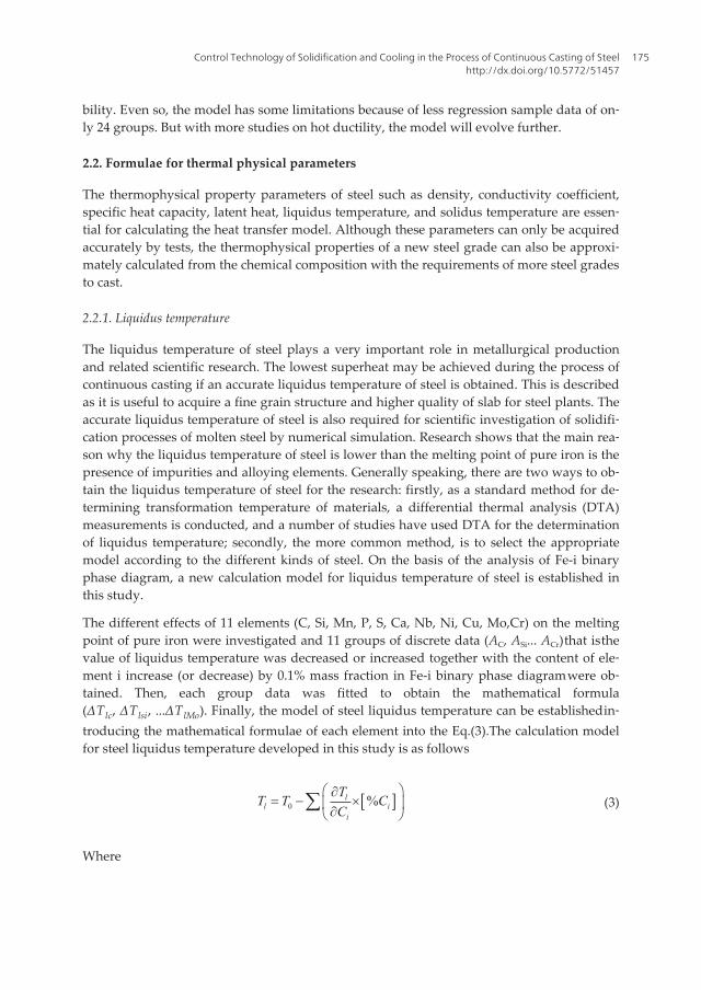
Figure 4. The influence of element i on the liquidus temperature
In Fig. 4, the X axis represents the mass percentage of element i and the Y axis repre‐sents temperature. The curve ADB is the change in the actual liquidus temperature withthe content of element I; however, most research on liquidus temperature assumed thatthe influence of each element on reduction value of the melting point is kept linear rela‐tion (shown as the straight-line segment AB). Therefore, the calculation is easy to result indeviation. For instance, when the content of the element i is C, the liquidus temperatureis the value corresponding to C (where point C corresponds to the liquidus temperature ac‐cording to traditional models), however �the actual liquidus temperature is Ti (correspond‐ing to point D). Therefore, the deviation is the line segment CD. As a result, the traditionalcalculation model for liquidus temperature of steel is likely to have a large error whensteel has many elements.
Owing to drawbacks of the general models for liquidus temperature calculation, a newmodel is needed. After differentiated the Fe-i binary phase diagram, new temperature coef‐ficients of each element in the molten steel is obtained, a new calculation model for liquidustemperature is established. The margin of error with the use of this universal model is likelyto be less than that with traditional models. All the alloying elements of steel or cast ironinfluence the liquidus temperature; however, the element which has the greatest effect is
Science and Technology of Casting Processes176
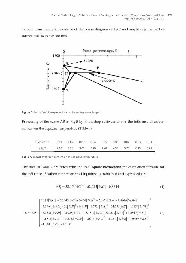
carbon. Considering an example of the phase diagram of Fe-C and amplifying the part of
interest will help explain this.
Figure 5. Partial Fe-C binary equilibrium phase diagram enlarged
Processing of the curve AB in Fig.5 by Photoshop software shows the influence of carbon
content on the liquidus temperature (Table 4).
CContent, % 0.01 0.02 0.03 0.04 0.05 0.06 0.07 0.08 0.09
△Tl ,℃ 2.00 2.50 3.00 3.40 4.40 4.90 5.70 6.10 6.70
Table 4. Impact of carbon content on the liquidus temperature
The data in Table 4 are fitted with the least square method�and the calculation formula for
the influence of carbon content on steel liquidus is established and expressed as:
[ ] [ ]232.15 % 62.645 % 0.8814kT C CD = + - (4)
[ ] [ ] [ ] [ ] [ ][ ] [ ] [ ] [ ] [ ] [ ][ ] [ ] [ ] [ ] [ ][ ] [ ] [ ] [ ]
2 2 2
2 2 2
2 2
2 2
31.15 % 62.645 % 0.609 % 2.0678 % 0.0674 %
5.3464 % 20 % 9 % 1.7724 % 24.775 % 1.1159 %
1538 5.3326 % 0.0758 % 3.1313 % 0.0379 % 5.2917 %
0.6818 % 2.5955 % 0.0214 % 3.2214 %l
C C Si Si Mn
Mn P P S S Nb
T Nb Ca Ca Ni Ni
Cu Cu Mo Mo
+ + + -
+ + + - + +
= - + - + + +
+ + + + [ ][ ]
20.0359 %
1.1402 % 10.797
Cr
Cr
æ öç ÷ç ÷ç ÷ç ÷ç ÷ç ÷+ç ÷+ +ç ÷è ø
(5)
Control Technology of Solidification and Cooling in the Process of Continuous Casting of Steelhttp://dx.doi.org/10.5772/51457
177
In the same way, for Si, Mn, P, S and other elements, their binary phase diagrams are proc‐essed, and different formular for each elements influence on the steel liquidus are obtained.Finally, a new model for calculating steel liquidus temperature is set up by synthesizing,which is verified with some testing liquidus temperature of steel, shown as Eq.(5).
It has been proved that errors between liquidus formula (5) with others are all less than 4 ℃.
2.2.2. Thermal conductivity coefficient
Thermal conductivity coefficient of steel solid-phase is relevant to temperature and ele‐ments. For carbon steels and stainless steels, the expression is shown as Eq. (6). Moreover,due to the great influence of liquid convection in liquid core, the equivalent thermal conduc‐tivity coefficient is used for liquid-phase.
[ ][ ] [ ]
[ ]
[ ][ ]
[ ] [ ] [ ]
[ ]
4
7 2 4 7
4 7 2
5
0.0124 2.204 1020.76 0.009 3.2627
1.078 10 7.822 10 1.741 10
0.5860 8.354 10 1.368 10 0.010670.7598 0.1432
1.504 10
0.2222
S TT C Cr
T Cr T Cr
T T NiNi Si Mn
T Ni
Mo
l-
- - -
- -
-
æ ö- ´= - - + ç ÷ç ÷+ ´ + ´ - ´ ×è ø
æ ö- + ´ - ´ ++ - -ç ÷ç ÷- ´ ×è ø-
(6)
L Sml l= (7)
( ) ( )( )1SL S LS Sf T f Tl l l= + - (8)
Where,
λL�λS�λSL— the conductivity coefficient of liquid phase, solid phase and mush zoon respective‐ly�W/(m ℃)�
T —Temperature�℃�
[i] —The mass percentage of the element i�%�
fS(T)—Solid fraction�
m —Equivalent coefficient.
2.2.3. Density
The density with high temperature of carbon steels is relevant to the carbon content andtemperature. Its solid, liquid density can be used formula (9), (10) to calculate.
Science and Technology of Casting Processes178
( )( )[ ]( )[ ]( )3
100 8245.2 0.51 273
100 1 0.008S
T
C Cr
- +=
- +(9)
[ ] [ ]( )( )7100 73 0.8 0.09 1550l C C Tr = - - - - (10)
But for stainless steels, it is strongly related to Cr, Ni, Mo, Mn, Si and other major elements,the expression is shown as formula (11), (12)�
[ ] [ ] [ ] [ ][ ] [ ]
( )79.6% 78.3% 85.4% 76.9%
0.5 2560.2% 47.1%s
Fe Cr Ni MnT
Mo Sir
æ ö+ + + += - -ç ÷ç ÷+è ø
(11)
[ ] [ ] [ ] [ ][ ] [ ]
( )69.4% 66.3% 71.4% 57.2%
0.86 155051.5% 49.3%l
Fe Cr Ni MnT
Mo Sir
æ ö+ + + += - -ç ÷ç ÷+è ø
(12)
( ) ( )( )1sl s S l Sf T f Tr r r= + - (13)
Where�
ρs�ρl�ρsl—The density of solid phase, liquid phase and mush zoon respectively�kg/m3�
T—Temperature�℃�
[i] —The mass percentage of the element i�%�
fS(T) —Solid fraction.
Moreover, formulae for specific heat and latent heat have been described in many researchliteratures. They will not be mentioned in this chapter.
Because thermal physical parameters have an important influence on the accuracy for theheat transfer calculation model, the database of thermal physical parameters, such as liq‐uidus temperature, conductivity coefficient, density and so on, has been established by sum‐marizing, which can provide accuracy “basic parameters” for the "targeted” solidificationand heat transfer numerical model.
3. Control models for secondary cooling in continuous casting process
Secondary cooling control, which is a key technology in the continuous casting process, notonly determines the productivity of a caster, but also significantly influences the quality of
Control Technology of Solidification and Cooling in the Process of Continuous Casting of Steelhttp://dx.doi.org/10.5772/51457
179
the slab. Currently, nearly all secondary cooling control systems are based on a heat transfermodel of solidification during continuous casting, which makes the control process morequantitative. At present, there are several popular control models for secondary cooling incontinuous casting, such as the parameter control model, effective-speed control model, on‐line thermal model, and models that are combinations of these. These control models havetheir respective advantages and meet the modern requirements of the continuous castingprocess on the whole. Even so�the mathematical heat transfer model of solidification is animportant base for secondary cooling control, so authors will briefly introduce it before ex‐pounding the control models of continuous casting.
3.1. Heat transfer model
The mathematical heat transfer model of solidification during continuous casting is com‐posed of heat conduction equations, initial conditions, and boundary conditions. The heatconduction along a strand is usually neglected. The unsteady two-dimensional equation ofheat transfer is shown as below:
p vT T Tc q
x x y yr l l
tæ ö¶ ¶ ¶ ¶ ¶æ ö= + +ç ÷ç ÷¶ ¶ ¶ ¶ ¶è ø è ø
(14)
Where, qv is internal heat source, which is latent heat (J kg-1) here and can be equivalent tothe equivalent specific heat capacity or effective thermal enthalpy to simplify the conductionequation. The heat transfer model is the basis for the quantitative method of controlling thesecondary cooling water, and many models of secondary cooling control have been devel‐oped. Some popular control models are reviewed in this chapter, as follows.
3.2. Control models for secondary cooling
3.2.1. Parameter control method
The parameter control method requires determination of the target surface temperaturecurves for different steel grades; calculation of the control parameters Ai, Bi, and Ci for everysecondary cooling zone such that the strand surface temperature coincides with the targetsurface temperature; and building a mathematical model as in equation (15).
2i i i iQ AV BV C= + + (15)
With the wide use of continuous temperature measurements of molten steel in the tund‐ish and growing research on the influence of the temperature of secondary cooling wa‐ter on slab cooling, the superheat and the temperature of the secondary cooling waterhave been considered to be the important factors for controlling the surface tempera‐ture of the slab. The secondary cooling water flow rate needs to be adjusted accord‐
Science and Technology of Casting Processes180
ing to these two factors, so equation (15) can be modified and improved, wherebyequation (16) is presented as follows:
2i i i i i iQ AV BV C D T F= + + + D + (16)
Where, Di is the adjusting parameter for the water flow rate based on superheat, and Fi is theadjusting parameter of water flow rate based on the temperature of the secondary coolingwater, which changes with the season.
The water flow rate in the parameter control method changes with the variation of castingspeed continuously, and are controlled according to the theory of the solidification of theslab and the practical conditions. The control pattern can be run in an automatic, manual, orsemi-automatic way. Indeed, the parameter control method requires little investment buthas strong applicability, and so is still widely applied in steel plants. However, the controlmethod shows an apparent disadvantage: the parameter control method cannot keep thestability of the slab surface temperature in the unsteady casting state, such as in the case of achange in the submerged entry nozzle and the hot exchange of the tundishes. Therefore, animproved control method called the “effective speed” method has been developed based onthe parameter control method.
3.2.2. Effective speed control method
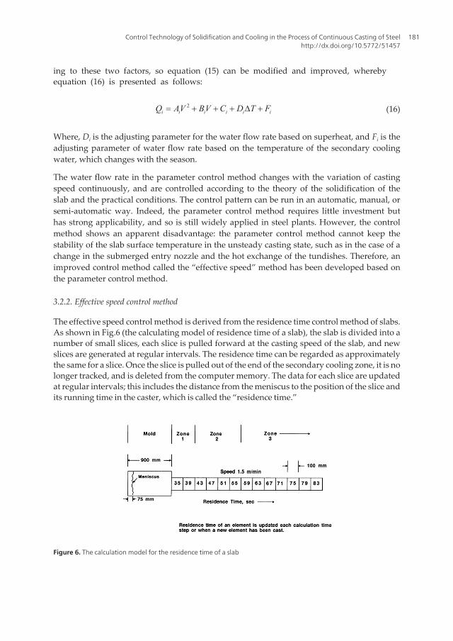
The effective speed control method is derived from the residence time control method of slabs.As shown in Fig.6 (the calculating model of residence time of a slab), the slab is divided into anumber of small slices, each slice is pulled forward at the casting speed of the slab, and newslices are generated at regular intervals. The residence time can be regarded as approximatelythe same for a slice. Once the slice is pulled out of the end of the secondary cooling zone, it is nolonger tracked, and is deleted from the computer memory. The data for each slice are updatedat regular intervals; this includes the distance from the meniscus to the position of the slice andits running time in the caster, which is called the “residence time.”
Figure 6. The calculation model for the residence time of a slab
Control Technology of Solidification and Cooling in the Process of Continuous Casting of Steelhttp://dx.doi.org/10.5772/51457
181
The relationship between the residence time and the water flow rate can be converted intothe relationship between the average speed and water flow rate. The average speed of onecooling zone can be calculated from equation (17):
1
1 i
iai n
rijji
SVt
n =
=×å (17)
It has been shown that a modified effective speed based on the average speed can be used toreduce surface temperature fluctuations and improve the safety of continuous casting opera‐tions. Effective speed can be calculated by equation (18):
( )1ei i ai iV V Ve e= + - (18)
Where, εi is the weighting coefficient, which is between 0 and 1, and depends on the dis‐tance from the center of the zone to the meniscus: i.e., the longer the distance, the higher isthe value.
The equation of the effective speed control method is constructed by replacing the real-timespeed in equation (15) with the effective speed, shown as below:
2i i ei i ei iQ AV BV C= + + (19)
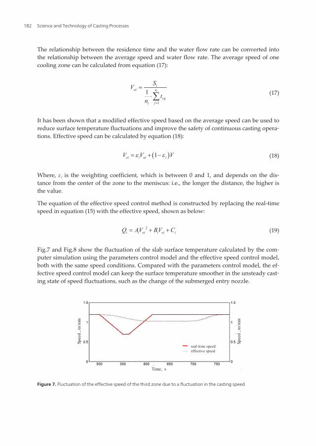
Fig.7 and Fig.8 show the fluctuation of the slab surface temperature calculated by the com‐puter simulation using the parameters control model and the effective speed control model,both with the same speed conditions. Compared with the parameters control model, the ef‐fective speed control model can keep the surface temperature smoother in the unsteady cast‐ing state of speed fluctuations, such as the change of the submerged entry nozzle.
Spee
d , m
/min
Spee
d , m
/min
Time, s
real-time speedeffective speed
Figure 7. Fluctuation of the effective speed of the third zone due to a fluctuation in the casting speed
Science and Technology of Casting Processes182
Surf
ace
tem
pera
ture
, �
Surf
ace
tem
pera
ture
, �
Time, s
parameters control modeleffective-speed control model
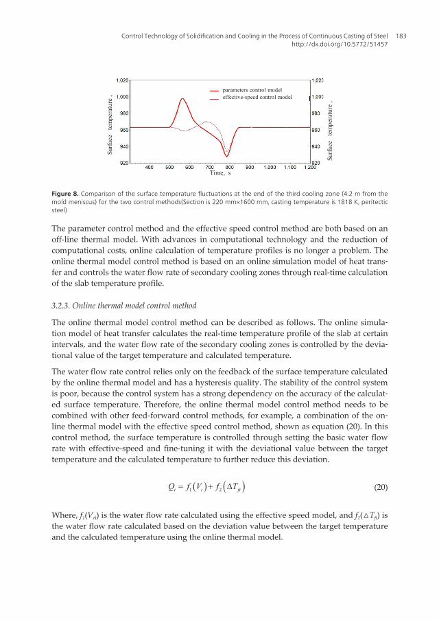
Figure 8. Comparison of the surface temperature fluctuations at the end of the third cooling zone (4.2 m from themold meniscus) for the two control methods(Section is 220 mm×1600 mm, casting temperature is 1818 K, peritecticsteel)
The parameter control method and the effective speed control method are both based on anoff-line thermal model. With advances in computational technology and the reduction ofcomputational costs, online calculation of temperature profiles is no longer a problem. Theonline thermal model control method is based on an online simulation model of heat trans‐fer and controls the water flow rate of secondary cooling zones through real-time calculationof the slab temperature profile.
3.2.3. Online thermal model control method
The online thermal model control method can be described as follows. The online simula‐tion model of heat transfer calculates the real-time temperature profile of the slab at certainintervals, and the water flow rate of the secondary cooling zones is controlled by the devia‐tional value of the target temperature and calculated temperature.
The water flow rate control relies only on the feedback of the surface temperature calculatedby the online thermal model and has a hysteresis quality. The stability of the control systemis poor, because the control system has a strong dependency on the accuracy of the calculat‐ed surface temperature. Therefore, the online thermal model control method needs to becombined with other feed-forward control methods, for example, a combination of the on‐line thermal model with the effective speed control method, shown as equation (20). In thiscontrol method, the surface temperature is controlled through setting the basic water flowrate with effective-speed and fine-tuning it with the deviational value between the targettemperature and the calculated temperature to further reduce this deviation.
( ) ( )1 2i i fiQ f V f T= + D (20)
Where, f1(Vei) is the water flow rate calculated using the effective speed model, and f2(△Tfi) isthe water flow rate calculated based on the deviation value between the target temperatureand the calculated temperature using the online thermal model.
Control Technology of Solidification and Cooling in the Process of Continuous Casting of Steelhttp://dx.doi.org/10.5772/51457
183
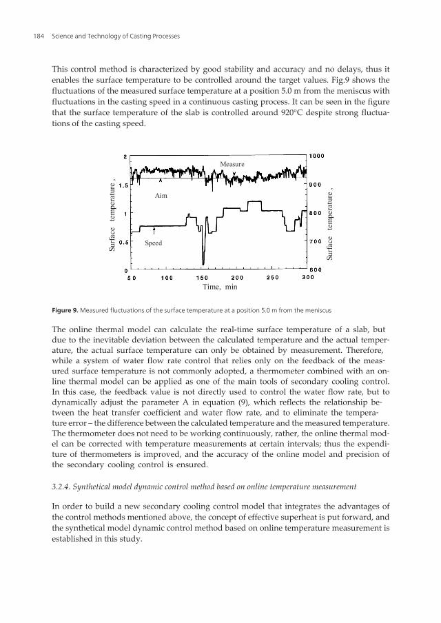
This control method is characterized by good stability and accuracy and no delays, thus itenables the surface temperature to be controlled around the target values. Fig.9 shows thefluctuations of the measured surface temperature at a position 5.0 m from the meniscus withfluctuations in the casting speed in a continuous casting process. It can be seen in the figurethat the surface temperature of the slab is controlled around 920°C despite strong fluctua‐tions of the casting speed.
Surf
ace
tem
pera
ture
, �
Surf
ace
tem
pera
ture
, �
Time, min
Speed
Aim
Measure
Figure 9. Measured fluctuations of the surface temperature at a position 5.0 m from the meniscus
The online thermal model can calculate the real-time surface temperature of a slab, butdue to the inevitable deviation between the calculated temperature and the actual temper‐ature, the actual surface temperature can only be obtained by measurement. Therefore,while a system of water flow rate control that relies only on the feedback of the meas‐ured surface temperature is not commonly adopted, a thermometer combined with an on‐line thermal model can be applied as one of the main tools of secondary cooling control.In this case, the feedback value is not directly used to control the water flow rate, but todynamically adjust the parameter A in equation (9), which reflects the relationship be‐tween the heat transfer coefficient and water flow rate, and to eliminate the tempera‐ture error – the difference between the calculated temperature and the measured temperature.The thermometer does not need to be working continuously, rather, the online thermal mod‐el can be corrected with temperature measurements at certain intervals; thus the expendi‐ture of thermometers is improved, and the accuracy of the online model and precision ofthe secondary cooling control is ensured.
3.2.4. Synthetical model dynamic control method based on online temperature measurement
In order to build a new secondary cooling control model that integrates the advantages ofthe control methods mentioned above, the concept of effective superheat is put forward, andthe synthetical model dynamic control method based on online temperature measurement isestablished in this study.
Science and Technology of Casting Processes184
Effective superheat is obtained by modifying the average superheat. In the parameter con‐trol method, the water flow rate compensation according to superheat is based on the real-time superheat, and this control model can meet the control requirements of the surfacetemperature only in the case of small fluctuations in the casting temperature. However, ifthe fluctuations are large, the surface temperature of the slab will not be controlled. In orderto achieve accurate water flow rate compensation according to superheat, the initial super‐heat in the meniscus of the slab should be obtained, and thus the average superheat needs tobe applied. In the residence time model of the slab (shown in Fig.6), the computer not onlycalculates the residence time of each slice, but also stores the data of the initial superheat ofeach slice when it is generated. The average superheat △Ta of one zone is the average valueof the initial superheats of all the slices in this cooling zone. The average superheat repre‐sents the initial superheat of the slab in a cooling zone, but there are shortcomings in apply‐ing this method. Because of the upper and lower convection from the liquid core, thetemperature of the liquid steel in the mold influences the temperature profile of a slab witha liquid pool. Furthermore, the shorter the distance of a cooling zone from the mold, thestronger is this effect. In addition, the water flow rate of the cooling zone closer to the moldcannot be adjusted in time when using the average superheat, thereby a breakout may hap‐pen if the casting temperature suddenly rises in the continuous casting process. Therefore,with regards to the effective speed, the average superheat should be corrected, and the effec‐tive superheat △Te, derived, as shown in equation (21):
( )1ei i ai iT T Tl lD = D + - D (21)
Where,ΔTei is the effective superheat of zone i �℃�;ΔTai, average superheat;ΔT , real timesuperheat; andλi the weighting coefficient, which ranges from 0 to 1. The weighting co‐efficient depends on the distance from the cooling zone to the meniscus: the furtherthe distance, the greater is the value. The value is 1 at the cooling zone of the solidi‐fication endpoint.
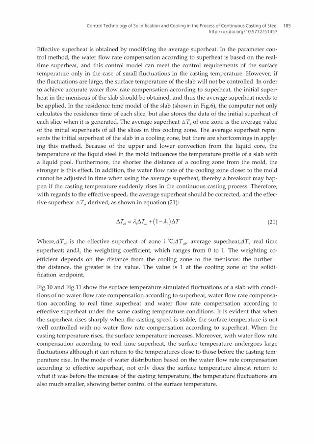
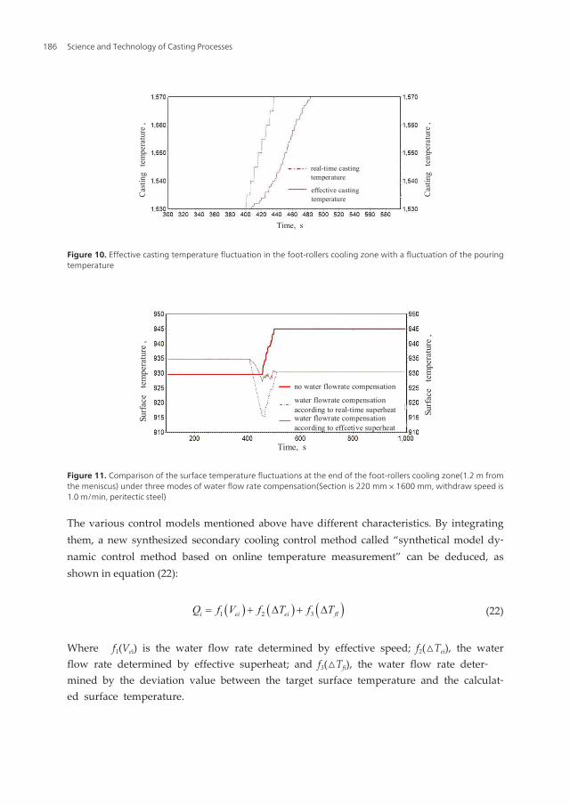
Fig.10 and Fig.11 show the surface temperature simulated fluctuations of a slab with condi‐tions of no water flow rate compensation according to superheat, water flow rate compensa‐tion according to real time superheat and water flow rate compensation according toeffective superheat under the same casting temperature conditions. It is evident that whenthe superheat rises sharply when the casting speed is stable, the surface temperature is notwell controlled with no water flow rate compensation according to superheat. When thecasting temperature rises, the surface temperature increases. Moreover, with water flow ratecompensation according to real time superheat, the surface temperature undergoes largefluctuations although it can return to the temperatures close to those before the casting tem‐perature rise. In the mode of water distribution based on the water flow rate compensationaccording to effective superheat, not only does the surface temperature almost return towhat it was before the increase of the casting temperature, the temperature fluctuations arealso much smaller, showing better control of the surface temperature.
Control Technology of Solidification and Cooling in the Process of Continuous Casting of Steelhttp://dx.doi.org/10.5772/51457
185
real-time castingtemperature
effective castingtemperatureC
astin
g t
empe
ratu
re ,
�
Cas
ting
tem
pera
ture
, �
Time, s
Figure 10. Effective casting temperature fluctuation in the foot-rollers cooling zone with a fluctuation of the pouringtemperature
Surf
ace
tem
pera
ture
, �
Surf
ace
tem
pera
ture
, �
no water flowrate compensation
water flowrate compensationaccording to real-time superheatwater flowrate compensationaccording to effcetive superheat
Time, s
Figure 11. Comparison of the surface temperature fluctuations at the end of the foot-rollers cooling zone(1.2 m fromthe meniscus) under three modes of water flow rate compensation(Section is 220 mm × 1600 mm, withdraw speed is1.0 m/min, peritectic steel)
The various control models mentioned above have different characteristics. By integratingthem, a new synthesized secondary cooling control method called “synthetical model dy‐namic control method based on online temperature measurement” can be deduced, asshown in equation (22):
( ) ( ) ( )1 2 3i ei ei flQ f V f T f T= + D + D (22)
Where � f1(Vei) is the water flow rate determined by effective speed; f2(△Tei), the waterflow rate determined by effective superheat; and f3(△Tfi), the water flow rate deter‐mined by the deviation value between the target surface temperature and the calculat‐ed surface temperature.
Science and Technology of Casting Processes186
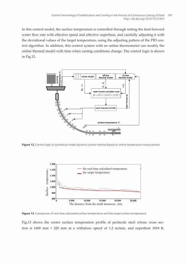
In this control model, the surface temperature is controlled through setting the feed-forwardwater flow rate with effective speed and effective superheat, and carefully adjusting it withthe deviational values of the target temperature, using the adjusting pattern of the PID con‐trol algorithm. In addition, this control system with an online thermometer can modify theonline thermal model with time when casting conditions change. The control logic is shownin Fig.12.
Figure 12. Control logic of synthetical model dynamic control method based on online temperature measurement
Surf
ace
tem
pera
ture
, �
The distance from the mold meniscus, mm
the real-time calculated temperaturethe target temperature
Figure 13. Comparison of real-time calculated surface temperature and the target surface temperature
Fig.13 shows the center surface temperature profile of peritectic steel whose cross sec‐tion is 1600 mm × 220 mm at a withdraw speed of 1.2 m/min, and superheat 1818 K.
Control Technology of Solidification and Cooling in the Process of Continuous Casting of Steelhttp://dx.doi.org/10.5772/51457
187
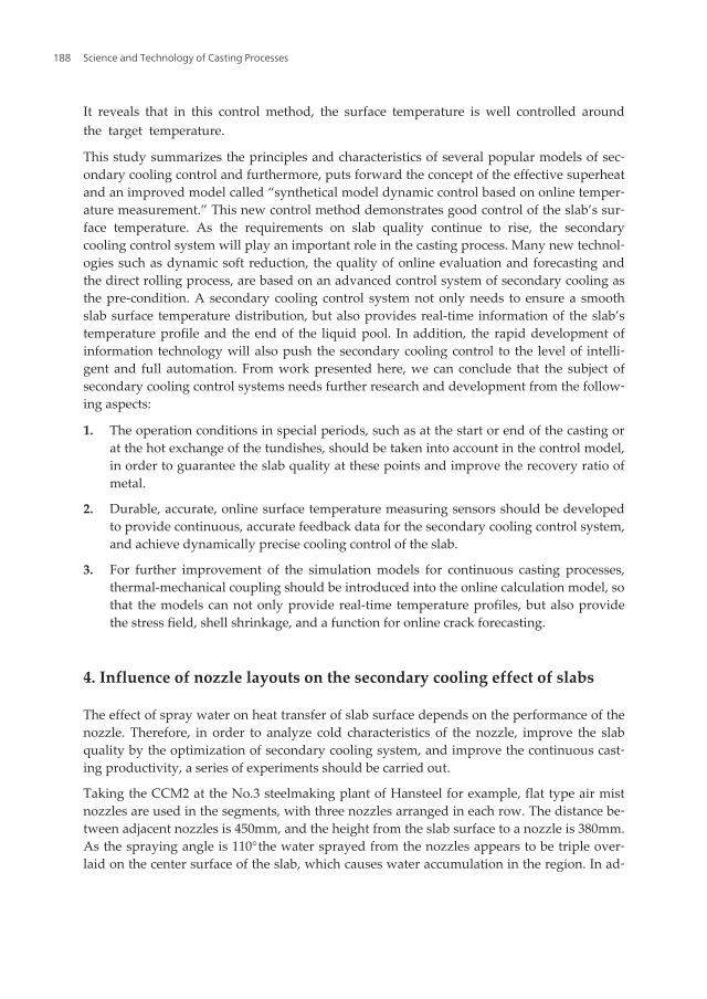
It reveals that in this control method, the surface temperature is well controlled aroundthe target temperature.
This study summarizes the principles and characteristics of several popular models of sec‐ondary cooling control and furthermore, puts forward the concept of the effective superheatand an improved model called “synthetical model dynamic control based on online temper‐ature measurement.” This new control method demonstrates good control of the slab’s sur‐face temperature. As the requirements on slab quality continue to rise, the secondarycooling control system will play an important role in the casting process. Many new technol‐ogies such as dynamic soft reduction, the quality of online evaluation and forecasting andthe direct rolling process, are based on an advanced control system of secondary cooling asthe pre-condition. A secondary cooling control system not only needs to ensure a smoothslab surface temperature distribution, but also provides real-time information of the slab’stemperature profile and the end of the liquid pool. In addition, the rapid development ofinformation technology will also push the secondary cooling control to the level of intelli‐gent and full automation. From work presented here, we can conclude that the subject ofsecondary cooling control systems needs further research and development from the follow‐ing aspects:
1. The operation conditions in special periods, such as at the start or end of the casting orat the hot exchange of the tundishes, should be taken into account in the control model,in order to guarantee the slab quality at these points and improve the recovery ratio ofmetal.
2. Durable, accurate, online surface temperature measuring sensors should be developedto provide continuous, accurate feedback data for the secondary cooling control system,and achieve dynamically precise cooling control of the slab.
3. For further improvement of the simulation models for continuous casting processes,thermal-mechanical coupling should be introduced into the online calculation model, sothat the models can not only provide real-time temperature profiles, but also providethe stress field, shell shrinkage, and a function for online crack forecasting.
4. Influence of nozzle layouts on the secondary cooling effect of slabs
The effect of spray water on heat transfer of slab surface depends on the performance of thenozzle. Therefore, in order to analyze cold characteristics of the nozzle, improve the slabquality by the optimization of secondary cooling system, and improve the continuous cast‐ing productivity, a series of experiments should be carried out.
Taking the CCM2 at the No.3 steelmaking plant of Hansteel for example, flat type air mistnozzles are used in the segments, with three nozzles arranged in each row. The distance be‐tween adjacent nozzles is 450mm, and the height from the slab surface to a nozzle is 380mm.As the spraying angle is 110°�the water sprayed from the nozzles appears to be triple over‐laid on the center surface of the slab, which causes water accumulation in the region. In ad‐
Science and Technology of Casting Processes188
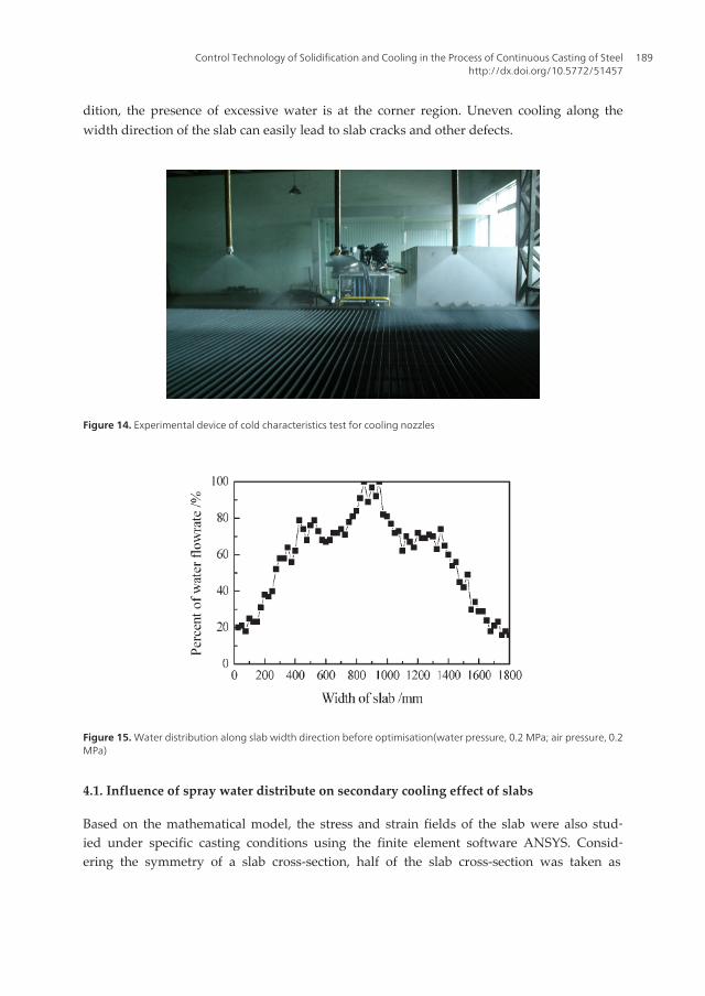
dition, the presence of excessive water is at the corner region. Uneven cooling along thewidth direction of the slab can easily lead to slab cracks and other defects.
Figure 14. Experimental device of cold characteristics test for cooling nozzles
Figure 15. Water distribution along slab width direction before optimisation(water pressure, 0.2 MPa; air pressure, 0.2MPa)
4.1. Influence of spray water distribute on secondary cooling effect of slabs
Based on the mathematical model, the stress and strain fields of the slab were also stud‐ied under specific casting conditions using the finite element software ANSYS. Consid‐ering the symmetry of a slab cross-section, half of the slab cross-section was taken as
Control Technology of Solidification and Cooling in the Process of Continuous Casting of Steelhttp://dx.doi.org/10.5772/51457
189
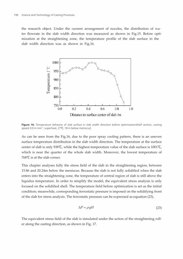
the research object. Under the current arrangement of nozzles, the distribution of wa‐ter flowrate in the slab width direction was measured as shown in Fig.15. Before opti‐mization at the straightening zone, the temperature profile of the slab surface in theslab width direction was as shown in Fig.16.
Figure 16. Temperature behavior of slab surface in slab width direction before optimization(Half section, castingspeed, 0.9 m min-1; superheat, 27℃, 18 m below meniscus)
As can be seen from the Fig.16, due to the poor spray cooling pattern, there is an unevensurface temperature distribution in the slab width direction. The temperature at the surfacecenter of slab is only 938℃, while the highest temperature value of the slab surface is 1001℃,which is near the quarter of the whole slab width. Moreover, the lowest temperature of768℃ is at the slab corner.
This chapter analyses fully the stress field of the slab in the straightening region, between15.86 and 20.24m below the meniscus. Because the slab is not fully solidified when the slabenters into the straightening zone, the temperature of central region of slab is still above theliquidus temperature. In order to simplify the model, the equivalent stress analysis is onlyfocused on the solidified shell. The temperature field before optimization is set as the initialcondition; meanwhile, corresponding ferrostatic pressure is imposed on the solidifying frontof the slab for stress analysis. The ferrostatic pressure can be expressed as equation (23).
P gHrD = (23)
The equivalent stress field of the slab is simulated under the action of the straightening roll‐er along the casting direction, as shown in Fig. 17.
Science and Technology of Casting Processes190
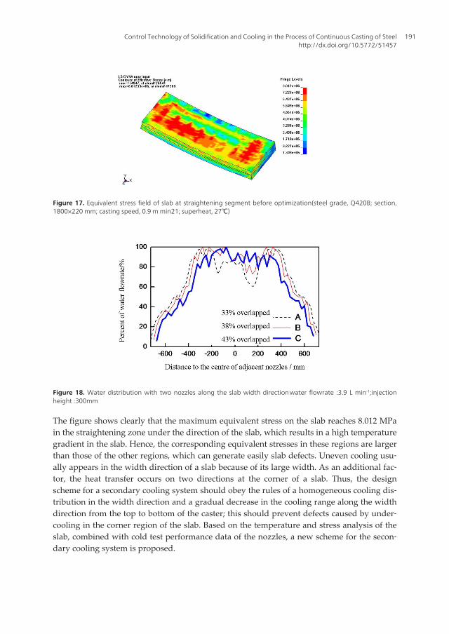
Figure 17. Equivalent stress field of slab at straightening segment before optimization(steel grade, Q420B; section,1800×220 mm; casting speed, 0.9 m min21; superheat, 27℃)
Figure 18. Water distribution with two nozzles along the slab width direction�water flowrate :3.9 L min-1;injectionheight :300mm�
The figure shows clearly that the maximum equivalent stress on the slab reaches 8.012 MPain the straightening zone under the direction of the slab, which results in a high temperaturegradient in the slab. Hence, the corresponding equivalent stresses in these regions are largerthan those of the other regions, which can generate easily slab defects. Uneven cooling usu‐ally appears in the width direction of a slab because of its large width. As an additional fac‐tor, the heat transfer occurs on two directions at the corner of a slab. Thus, the designscheme for a secondary cooling system should obey the rules of a homogeneous cooling dis‐tribution in the width direction and a gradual decrease in the cooling range along the widthdirection from the top to bottom of the caster; this should prevent defects caused by under‐cooling in the corner region of the slab. Based on the temperature and stress analysis of theslab, combined with cold test performance data of the nozzles, a new scheme for the secon‐dary cooling system is proposed.
Control Technology of Solidification and Cooling in the Process of Continuous Casting of Steelhttp://dx.doi.org/10.5772/51457
191
4.2. Influence of nozzle layouts on the spray water distribution
The principle of nozzles arrangement is to make spray water distribute evenly in the widthdirection of slab surface. Through a series of test for combined nozzles on the platform ofnozzle automatic testing, the relationship between spraying overlap degree of adjacent noz‐zles and the uniformity of water distribution in slab width direction is analyzed from threeaspects such as nozzle flow rate, injection height, water pressure and air pressure.
As can be seen from Fig.18�water distribution of scheme C whose spray overlap degree ofadjacent nozzles is 43%, is more even in slab width direction when the water flow rate is 3.9L min-1 and injection height is 300 mm.
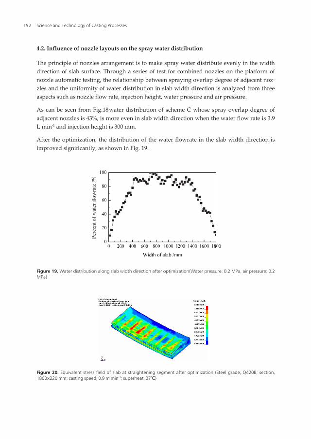
After the optimization, the distribution of the water flowrate in the slab width direction isimproved significantly, as shown in Fig. 19.
Figure 19. Water distribution along slab width direction after optimization(Water pressure: 0.2 MPa, air pressure: 0.2MPa)
Figure 20. Equivalent stress field of slab at straightening segment after optimization (Steel grade, Q420B; section,1800×220 mm; casting speed, 0.9 m min-1; superheat, 27℃)
Science and Technology of Casting Processes192
On the basis of the optimization of the temperature field, the stress field of a slab at thestraightening zone was analyzed. The simulation results for the equivalent stress field in thestraightening zone of the slab after optimization are shown in Fig. 20.
Comparison of Figs. 17and 20 shows that although the maximum values of equivalent stressdecrease from 8.012 to 8.000 MPa after optimization (only reduced by 0.012 MPa), the stressconcentration has almost disappeared. The larger stresses shown in Fig. 13 exist only wherethe slab and the rollers are in contact because of the ferrostatic pressure of the molten steel.However, a wide range of slab surface was under the state of large equivalent stress beforeoptimization, which was harmful to the surface quality of the slab. In the software simula‐tion, the temperature and stress fields were both greatly improved, which was useful to im‐prove the quality of the slab.
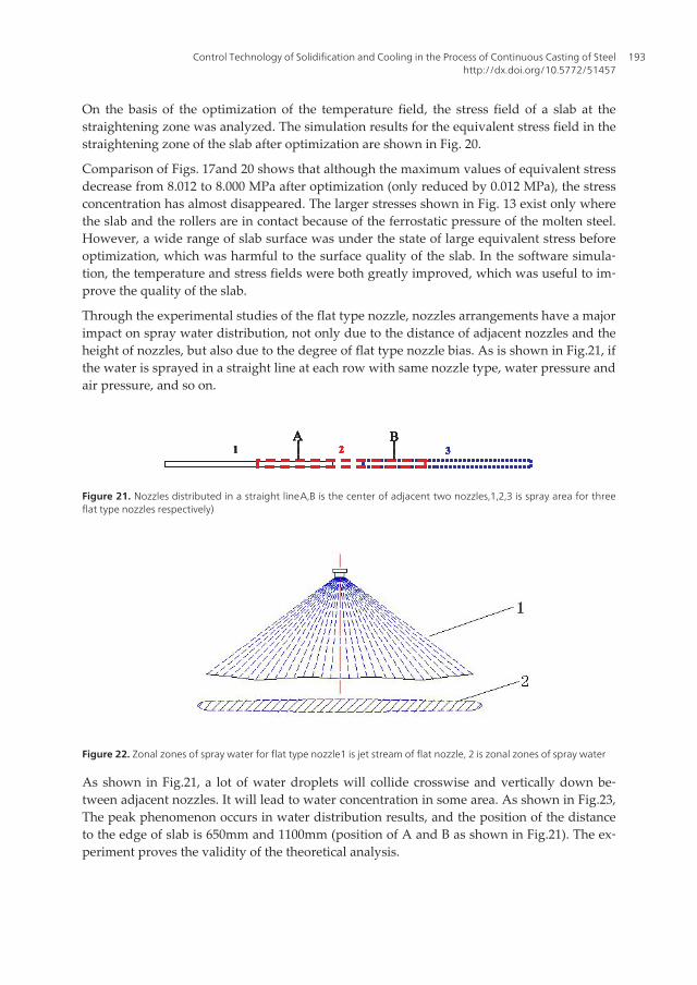
Through the experimental studies of the flat type nozzle, nozzles arrangements have a majorimpact on spray water distribution, not only due to the distance of adjacent nozzles and theheight of nozzles, but also due to the degree of flat type nozzle bias. As is shown in Fig.21, ifthe water is sprayed in a straight line at each row with same nozzle type, water pressure andair pressure, and so on.
1 32A B
1 32A B
1 32A B
11 32A B
332A B
2A
22A B
Figure 21. Nozzles distributed in a straight line�A,B is the center of adjacent two nozzles,1,2,3 is spray area for threeflat type nozzles respectively)
Figure 22. Zonal zones of spray water for flat type nozzle�1 is jet stream of flat nozzle, 2 is zonal zones of spray water�
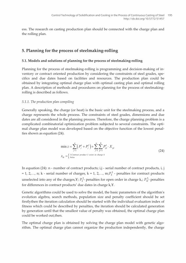
As shown in Fig.21, a lot of water droplets will collide crosswise and vertically down be‐tween adjacent nozzles. It will lead to water concentration in some area. As shown in Fig.23,The peak phenomenon occurs in water distribution results, and the position of the distanceto the edge of slab is 650mm and 1100mm (position of A and B as shown in Fig.21). The ex‐periment proves the validity of the theoretical analysis.
Control Technology of Solidification and Cooling in the Process of Continuous Casting of Steelhttp://dx.doi.org/10.5772/51457
193
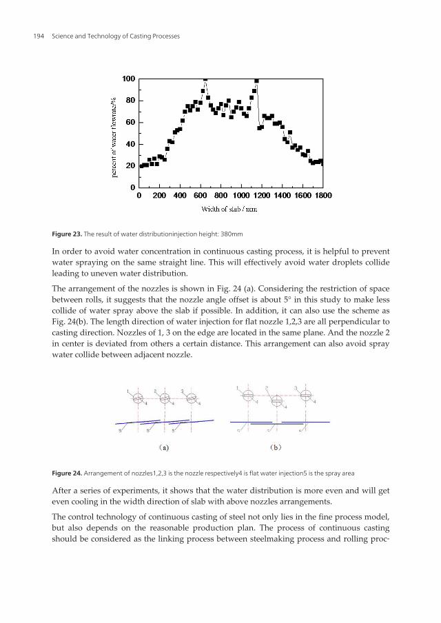
Figure 23. The result of water distribution�injection height: 380mm�
In order to avoid water concentration in continuous casting process, it is helpful to preventwater spraying on the same straight line. This will effectively avoid water droplets collideleading to uneven water distribution.
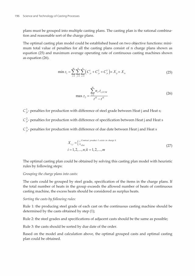
The arrangement of the nozzles is shown in Fig. 24 (a). Considering the restriction of spacebetween rolls, it suggests that the nozzle angle offset is about 5° in this study to make lesscollide of water spray above the slab if possible. In addition, it can also use the scheme asFig. 24(b). The length direction of water injection for flat nozzle 1,2,3 are all perpendicular tocasting direction. Nozzles of 1, 3 on the edge are located in the same plane. And the nozzle 2in center is deviated from others a certain distance. This arrangement can also avoid spraywater collide between adjacent nozzle.
Figure 24. Arrangement of nozzles�1,2,3 is the nozzle respectively�4 is flat water injection�5 is the spray area�
After a series of experiments, it shows that the water distribution is more even and will geteven cooling in the width direction of slab with above nozzles arrangements.
The control technology of continuous casting of steel not only lies in the fine process model,but also depends on the reasonable production plan. The process of continuous castingshould be considered as the linking process between steelmaking process and rolling proc‐
Science and Technology of Casting Processes194
ess. The research on casting production plan should be connected with the charge plan andthe rolling plan.
5. Planning for the process of steelmaking-rolling
5.1. Models and solutions of planning for the process of steelmaking-rolling
Planning for the process of steelmaking-rolling is programming and decision-making of in‐ventory or contract oriented production by considering the constraints of steel grades, spe‐cifics and due dates based on facilities and resources. The production plan could beobtained by integrating optimal charge plan with optimal casting plan and optimal rollingplan. A description of methods and procedures on planning for the process of steelmaking-rolling is described as follows.
5.1.1. The production plan compiling
Generally speaking, the charge (or heat) is the basic unit for the steelmaking process, and acharge represents the whole process. The constraints of steel grades, dimensions and duedates are all considered in the planning process. Therefore, the charge planning problem is acomplicated combinatorial optimization problem subjected to several constraints. The opti‐mal charge plan model was developed based on the objective function of the lowest penal‐ties shown as equation (24).
( )
{
01 2 3
1 1 1
1 0
minn n
j j pj pjj j p
Contract product I exists in charge kik else
z P P P X
x= = =
= + + ×
=
å åå(24)
In equation (24): n - number of contract products; i,j - serial number of contract products, i, j= 1, 2,…, n; k - serial number of charges, k = 1, 2,…, m;Pk
1 - penalties for contract products
unselected into any of the charges,Ұ; Pk2- penalties for open order in charge k,�; Pik
3- penaltiesfor differences in contract products’ due dates in charge k,Ұ.
Genetic algorithms could be used to solve the model, the basic parameters of the algorithm'sevolution algebra, search methods, population size and penalty coefficient should be setfirstly�then the iteration calculation should be started with the individual evaluation index offitness which could be described by penalties, the iteration should be calculated generationby generation until that the smallest value of penalty was obtained, the optimal charge plancould be worked out,then.
The optimal charge plan is obtained by solving the charge plan model with genetic algo‐rithm. The optimal charge plan cannot organize the production independently, the charge
Control Technology of Solidification and Cooling in the Process of Continuous Casting of Steelhttp://dx.doi.org/10.5772/51457
195
plans must be grouped into multiple casting plans. The casting plan is the rational combina‐tion and reasonable sort of the charge plans.
The optimal casting plan model could be established based on two objective functions: mini‐mum total value of penalties for all the casting plans consist of n charge plans shown asequation (25) and maximum average operating rate of continuous casting machines shownas equation (26).
( )1 2 31
1 1 1min
m n n
js js js ij isi j s
z C C C X X= = =
= + + ´ ´ååå (25)
,1
2
,max
m
i i CCMi
iE iS
n tz
t t==
-
å (26)
C js1 - penalties for production with difference of steel grade between Heat j and Heat s;
C js2 - penalties for production with difference of specification between Heat j and Heat s�
C js3 - penalties for production with difference of due date between Heat j and Heat s�
{ 1, 0
1,2,..., ; 1, 2,...,
Contract product I exists in charge k
i j elseX
i n k m
=
= =(27)
The optimal casting plan could be obtained by solving this casting plan model with heuristicrules by following steps:
Grouping the charge plans into casts:
The casts could be grouped by steel grade, specification of the items in the charge plans. Ifthe total number of heats in the group exceeds the allowed number of heats of continuouscasting machine, the excess heats should be considered as surplus heats.
Sorting the casts by following rules:
Rule 1: the producing steel grade of each cast on the continuous casting machine should bedetermined by the casts obtained by step (1);
Rule 2: the steel grades and specifications of adjacent casts should be the same as possible;
Rule 3: the casts should be sorted by due date of the order.
Based on the model and calculation above, the optimal grouped casts and optimal castingplan could be obtained.
Science and Technology of Casting Processes196
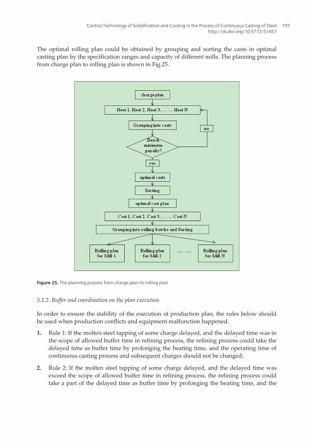
The optimal rolling plan could be obtained by grouping and sorting the casts in optimalcasting plan by the specification ranges and capacity of different mills. The planning processfrom charge plan to rolling plan is shown in Fig.25.
Figure 25. The planning process from charge plan to rolling plan
5.1.2. Buffer and coordination on the plan execution
In order to ensure the stability of the execution of production plan, the rules below shouldbe used when production conflicts and equipment malfunction happened.
1. Rule 1: If the molten steel tapping of some charge delayed, and the delayed time was inthe scope of allowed buffer time in refining process, the refining process could take thedelayed time as buffer time by prolonging the heating time, and the operating time ofcontinuous casting process and subsequent charges should not be changed;
2. Rule 2: If the molten steel tapping of some charge delayed, and the delayed time wasexceed the scope of allowed buffer time in refining process, the refining process couldtake a part of the delayed time as buffer time by prolonging the heating time, and the
Control Technology of Solidification and Cooling in the Process of Continuous Casting of Steelhttp://dx.doi.org/10.5772/51457
197
continuous casting process could take the rest of the delayed time as buffer time bylowering the casting speed;
3. Rule 3: If the molten steel tapping of some charge delayed, and the delayed time wasexceed the scope of total allowed buffer time in refining process and continuous castingprocess, the continuous casting machine should stop working;
4. Rule 4: If the continuous casting production of some cast delayed, and the delayed timewas in the scope of allowed buffer time in reheating process, the reheating processcould take the delayed time as buffer time by changing the heating time and intensity,and the operating time of rolling process should not be changed;
5. Rule 5: If the continuous casting production of some cast delayed, and the delayed timewas exceed the scope of allowed buffer time in reheating process, the rolling processshould use the intermediate inventory for production.
In the dynamic execution of planning, production conflicts and equipment malfunctioncould be regulated dynamically by the proposed rules in order to ensure the implementa‐tion of the production plan running steadily.
5.2. Examples of planning for the process of steelmaking-rolling
5.2.1. Rule based planning system on the process of steelmaking-rolling in plant A
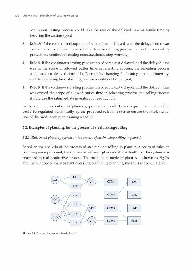
Based on the analysis of the process of steelmaking-rolling in plant A, a series of rules onplanning were proposed, the optimal rule-based plan model was built up. The system waspracticed in real productive process. The production mode of plant A is shown as Fig.26,and the window of management of casting plan in the planning system is shown in Fig.27.
Figure 26. The production mode of plant A
Science and Technology of Casting Processes198
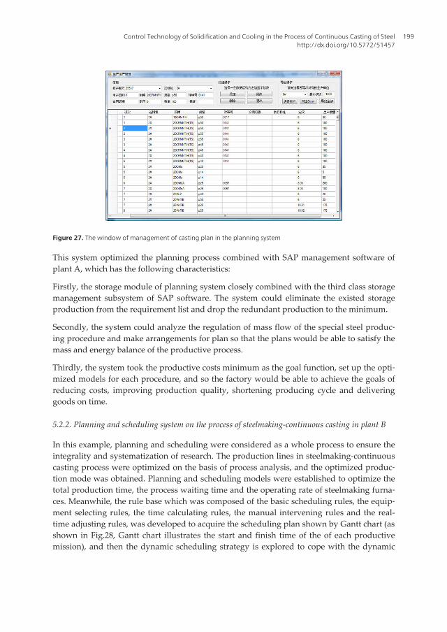
Figure 27. The window of management of casting plan in the planning system
This system optimized the planning process combined with SAP management software ofplant A, which has the following characteristics:
Firstly, the storage module of planning system closely combined with the third class storagemanagement subsystem of SAP software. The system could eliminate the existed storageproduction from the requirement list and drop the redundant production to the minimum.
Secondly, the system could analyze the regulation of mass flow of the special steel produc‐ing procedure and make arrangements for plan so that the plans would be able to satisfy themass and energy balance of the productive process.
Thirdly, the system took the productive costs minimum as the goal function, set up the opti‐mized models for each procedure, and so the factory would be able to achieve the goals ofreducing costs, improving production quality, shortening producing cycle and deliveringgoods on time.
5.2.2. Planning and scheduling system on the process of steelmaking-continuous casting in plant B
In this example, planning and scheduling were considered as a whole process to ensure theintegrality and systematization of research. The production lines in steelmaking-continuouscasting process were optimized on the basis of process analysis, and the optimized produc‐tion mode was obtained. Planning and scheduling models were established to optimize thetotal production time, the process waiting time and the operating rate of steelmaking furna‐ces. Meanwhile, the rule base which was composed of the basic scheduling rules, the equip‐ment selecting rules, the time calculating rules, the manual intervening rules and the real-time adjusting rules, was developed to acquire the scheduling plan shown by Gantt chart (asshown in Fig.28, Gantt chart illustrates the start and finish time of the of each productivemission), and then the dynamic scheduling strategy is explored to cope with the dynamic
Control Technology of Solidification and Cooling in the Process of Continuous Casting of Steelhttp://dx.doi.org/10.5772/51457
199
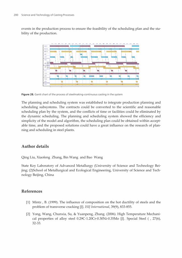
events in the production process to ensure the feasibility of the scheduling plan and the sta‐bility of the production.
Figure 28. Gantt chart of the process of steelmaking-continuous casting in the system
The planning and scheduling system was established to integrate production planning andscheduling subsystems. The contracts could be converted to the scientific and reasonablescheduling plan by the system, and the conflicts of time or facilities could be eliminated bythe dynamic scheduling. The planning and scheduling system showed the efficiency andsimplicity of the model and algorithm, the scheduling plan could be obtained within accept‐able time, and the proposed solutions could have a great influence on the research of plan‐ning and scheduling in steel plants.
Author details
Qing Liu, Xiaofeng Zhang, Bin Wang and Bao Wang
State Key Laboratory of Advanced Metallurgy (University of Science and Technology Bei‐jing; (2)School of Metallurgical and Ecological Engineering, University of Science and Tech‐nology Beijing, China
References
[1] Mintz , B. (1999). The influence of composition on the hot ductility of steels and theproblem of transverse cracking [J]�. ISIJ International, 39(9), 833-855.
[2] Yong, Wang, Chunxia, Su, & Yuanpeng, Zhang. (2006). High Temperature Mechani‐cal properties of alloy steel 0.29C-1.20Cr-0.30Ni-0.35Mo [J] �. Special Steel ( , 27(6),32-33.
Science and Technology of Casting Processes200
[3] Xiaoqun, He. (2008). Applied Regression Analysis [M]�. Beijing China�Higher EducationPress.
[4] Qiaodan, Lu, Zhiyuan, Zhu, Wanjun, Wang, et al. (2002). Influence of calcium treat‐ment on hot ductility of steel for container [J]�. Iron and Steel, 37(6), 35-38.
[5] Wang, Xin, Wang, Xianyong, Wang, Bao, et al. (2011). Differential Calculation Modelfor Liquidus Temperature of Steel [J]�. steel research international, 82(3), 164-168.
[6] Wu, Y. J., Jiang, Z. H., Liang, L. K., et al. (2002). Calculation on Liquidus temperatureof Steel [J]. Journal of Iron and Steel Research, 14(6), 6-9.
[7] Dong, H. B., & Brooks, R. (2005). Determination of Liquid Journal of Chongqing Uni‐veus temperature in Al-Si and Al-Si-Mg Alloys using a Single-pan Scanning Calorim‐eter [J]�. Materials Science and Engineering A, 413, 480-484.
[8] Miettinen, J. (1997). Calculation of solidification-related thermophysical propertiesfor steel [J]�. Metallurgical and Materials Transactions B, 28B(2), 281-297.
[9] Mills, K. C. (2004). Equations for the Calculation of the Thermophysical Properties ofStainless Steel [J]�. ISIJ International, 44(10), 1661-1668.
[10] Zhichao, Dou, Liu, Qing, Wang, Bao, et al. (2011). Evolution of Control Models forSecondary Cooling in Continuous Casting Process of Steel [J]�. steel research interna‐tional, 82(10), 1220-1227.
[11] Zhao, Jiagui, Qu, Xiuli, Cai, Kaike, et al. (2000). A secondary spray water cooling con‐trol model for slab caster and its application [J]�. Metallurgical Industry Automation,24(3), 34-36.
[12] Liu, Qing, Wang, Liangzhou, Zhang, Liqiang, et al. (2008). Mathematical model ofheat transfer for bloom continuous casting [J]�. Journal of University of Science and Tech‐nology Beijing, 15(1), 17-23.
[13] Chen, Dengfu, Li, Hongliang, Niu, Hongbo, et al. (2007). New Model for SprayingWater of Nozzles in Secondary Cooling of Billet Continuous Casting [J]�. Journal ofChongqing University (Natural Science Edition), 30(6), 61-64.
[14] Han, Peng, & Zhang, Xingzhong. (2002). Non-Steady Control of Secondary CoolingUsed for Continuous Casting Slab [J]�. Journal of Iron and Steel Research, 14(4), 73-76.
[15] Gilles, Herbert L. (2003). Primary and Secondary Cooling Control [M] . The castingvolume of the 11th edition of the making, shaping and treating of steel ,AISE, 33-44.
[16] Kondo, Osamu, Hamada, Katushige, Kuribayashi, Takashi, et al. (1993). New dy‐namic spray control system for secondary cooling zone of continuous casting ma‐chine [M]. Steelmaking Conference Proceedings�Dallas, 309-314.
[17] Kawasaki, S., Arita, H., Kikunaga, M., Chida, Y., et al. (1984). On the Secondary Cool‐ing Control Technology for the Continuous Casting [J]�. Direct Rolling Process�NipponSteel Tech-nical Report, 23, 69-76.
Control Technology of Solidification and Cooling in the Process of Continuous Casting of Steelhttp://dx.doi.org/10.5772/51457
201
[18] Morita, T., Konishi, M., Kitamura, A., et al. (1986). Control Method of Secondary‐Cooling Water for Bloom Continuous Casting. Kobelco Technical Bulletin�, 1109, 1-5.
[19] Barozzi, P., Fontana, P., & Pragliola, P. (1986). Computer Control and Optimizationof Secondary Cooling During Continuous Casting. Iron and Steel Engineer, 63(11),21-26.
[20] Liu, Weitao, Bai, Jubing, Qian, Liang, et al. (2008). Application of Dynamic SecondaryCooling in Continuous Casting of Steel Slab [J]. Foundry Technology [12], 1651-1654.
[21] Guo, Liangliang, Tian, Yong, yao, Man, et al. (2009). Temperature distribution anddynamic control of secondary cooling in slab continuous casting [J]. InternationalJournal of Minerals, Metallurgy and Materials, 16(6), 626-631.
[22] Zhang, Zheng Shan, Chai, Tianyou, Wang, Wei, et al. (1999). Secondary cooling con‐trol for alloy steel billet continuous caster in Fushun Special Steel Co Ltd [J]. Metal‐lurgical Industry Automation, , , 23(5), 32-35.
[23] Takawa, T., Takahashi, R., & Tatsuwaki, M. (1987). Mathematical Model and ControlSystem of Cooling Process. The Sumitomo Search, 34, 79-87.
[24] Morwald, K., Dittenberger, K., & Ives, K. D. (1998). Dynacs cooling system-featuresand operational results [J] �. Ironmaking & Steelmaking, 25(4), 323-327.
[25] Hardin, Richarda, Liu, Kai, Kapoor, Atul, et al. (2003). A transient simulation and dy‐namic spray cooling control model for continuous steel casting. Metallurgical and Ma‐terials Transactions B, 34B(3), 297-306.
[26] Okuno, K., Naruwa, H., & Kuribayashi, T. (1987). Dynacs spray cooling control sys‐tem for continuous casting [J]. Iron and Steel Engineer, 64(4), 34-38.
[27] Spitzer, K.H., Harste, K., Weber, B., et al. (1992). Mathematical model for thermaltracking and on-line control in continuous casting [J]. ISIJ International, 32(7), 848-856.
[28] Camisani-Calzolari, F.R., Craig, I.K., & Pistorius, P.C. (2000). Speed disturbance com‐pensation in the secondary cooling zone in continuous casting [J]. ISIJ International,40(5), 469-477.
[29] Liu, Wen-kai, Xie, Zhi, Ji, Zhen-ping, et al. (2008). Dynamic water modeling and ap‐plication of billet continuous casting [J]. Journal of Iron and Steel Research International,15(2), 14-17.
[30] Cai, Ji, Zhang, Shuyan, zhao, Qi, et al. (2005). Study and implement of real-timpera‐ture field calculation and secondary cooling control model for slab caster with dy‐namic soft reduction [M]. CSM 2005 Annual Meeting Proceedings, Beijing, 3, 340-345.
[31] Xianyong, Wang, Qing, Liu, & Zhigang, Hu. (2010). Influence of nozzle layouts onthe secondary cooling effect ofmedium thickness slabs i n continuous casting [J]�. Jour‐nal of University of Science and Technology Beijing, 32(8).
Science and Technology of Casting Processes202
[32] Wang, Xianyong, Liu, Qing, Wang, Xin, et al. (2011). Optimal control of secondarycooling for medium-thickness slab continuous casting. Ironmaking & Steelmaking [J],38(7), 552-560.
[33] Qing, Liu. (2002). Research on mode optimization of modern BOF steelmaking work‐shop for long products-the effect of high efficiency continuous casting technology onrunning control for modern BOF steelmaking workshop. Beijing: University of Scienceand Technology Beijing.
[34] Qing, Liu, Bai, Suhong, Lu, Junhui, et al. (2008). Production plan schedule for thecasting-rolling process in BOF special steel plants [J]. Journal of University of Scienceand Technology Beijing, 30(5), 566-570.
[35] Bin, Wang. (2009). Research on planning and dispatching of steelmaking-rollingprocess at Shijiazhuang iron and sSteel corporation [D]. Beijing: University of Scienceand Technology Beijing.
[36] Chuang, Wang. (2012). Research on production planning and scheduling system forsteelmaking-continuous casting process in the special steel workshop [D]. Beijing:University of Science and Technology Beijing.
[37] Gantt, H. L. (1910). Work, Wages, Profit. The management of projects [M]. The Engi‐neering Magazine, New York.
Control Technology of Solidification and Cooling in the Process of Continuous Casting of Steelhttp://dx.doi.org/10.5772/51457
203