Embed Size (px)
Citation preview
2018-10-12 _75122200429
Control System - ICS
Volvo EWR 150E & 170EVolvo EW 160E, 180E & 220E
Translation of the Original Instructions _EN
© Rototilt Group AB 2018-10-12
5
2 31
64 7
EN English
Overview
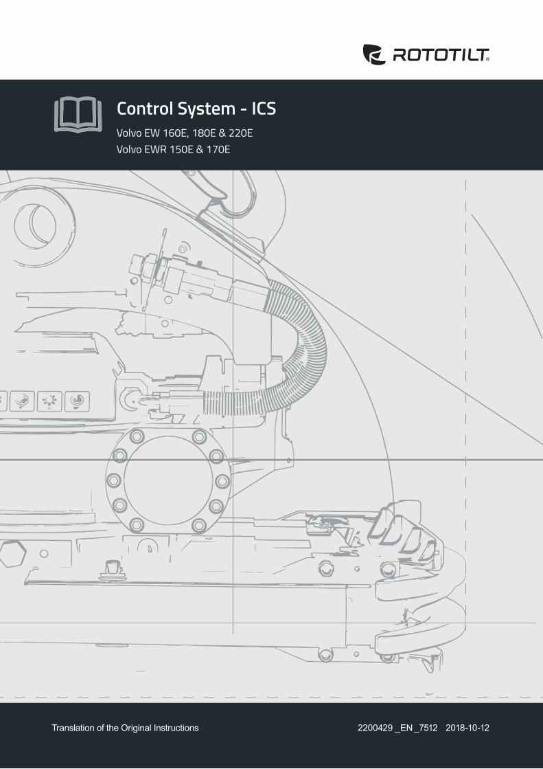
The product described in the document consists of components for the ICS control system. The overviews show standard equipment and options.
Refer to the figures and lists below as well as on the following pages.
ICS control systemICS control system consists of the following components:
1. Harness, boom Contact (SecureLock, machine coupler) Contact with safety plug
2. Display Switch for tool replacement. Cab control unit, CCU
3. Handles with controls to operate Rototilt® functions and base machine functions are ordered separately
4. Locking cylinder sensor. (ICS SecureLock) LED lighting. (ICS SecureLock)
5. Valve block Electric swivel
6. Rototilt® control unit, TCU
Zero-position sensor. (ICS sensor, ICS SecureLock) Frequency sensor. (ICS sensor, ICS SecureLock)
7. Connection to the base machine control unit.
!IMPORTANT - Read the Instructions for Use for the control system, tiltrotator and base machine before starting work. Pay particular attention to the safety instructions.
! IMPORTANT - Pressurising the Rototilt® hydraulic system means that the quick coupler locking function will be pressurised.
!IMPORTANT - Connected safety plug ensures that the base machine’s quick coupler is not opened accidentally during use of the tiltrotator.
2200429_ _7512

© Rototilt Group AB 2018-10-12
!
PULSATING LIGHT
FIXED LIGHT
TCU
CCU
Sound
Light
Power
CAN-bus
Internal Error
LED INDICATIONSOK Error
EN English
Control unitThe control units have three LEDs: green, orange and red. When the system is working correctly, all LEDs light and with no flashing. When a malfunction occurs the relevant LED begins flashing.
PWR (green) shows whether the unit is powered up. CAN (orange) shows whether communications with CAN bus are working.SYS (red) shows whether the unit’s internal components are working correctly.
The control units are not interchangeable.
Cab control unit, CCUThe control unit receives signals from the handles and switches.The control unit sends signals to the valve block shunt and tiltrotator via CAN bus.
Rototilt® control unit, TCUThe control unit receives signals from the cab control unit, and from sensors in Rototilt®.Rototilt® control unit sends signals to valves and LED lamp.There is a sensor in the Rototilt® control unit that detects the tilt angle.
!IMPORTANT - The control units have a similar appearance but the content differs. They are not interchangeable.
DisplaySettings, calibration and activation of certain functions are made via the display and its keys.
There is a buzzer in the display that sounds to attract the operator’s attention if the quick coupler locking function is open or in the event of a fault.
Switch, quick coupler locking functionThe quick coupler locking function switch is interlocked. This prevents accidental activation of the quick coupler locking function.
!WARNING! A problem has occurred if the buzzer sounds without activating the quick coupler locking function switch. The display shows information about the current problem.
2200429_ _7512
© Rototilt Group AB 2018-10-12
2017-07-04 2200002
Rototilt®
6679SE - Bruksanvisning i original _SE
2017-10-13 _68002200212
Control System - ICS
SE - Bruksanvisning i original _SE
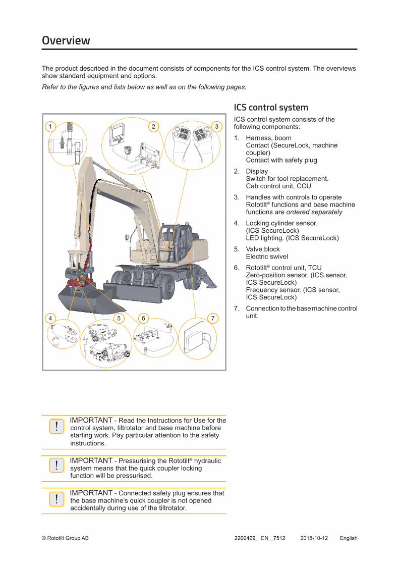
ECU = Excavator Control Unit
Refer to Basemachine´s “Instructions for Use” and/or “Schematics” to locate ECU in question.
Se basmaskinens bruksanvisning och/eller schema för att lokalisera aktuell ECU.
EN English
Machine controlMachine control regulates the oil flow to the hydraulic circuit for extra equipment on the base machine. Movement of the rollers in the handles affects the oil flow in the machine's main valve via the control unit.
The system has two different functions:
Rototilt® control
When the 8-pole connector on the stick is connected, a flow is regulated parallel to the valves on Rototilt ® and the hydraulic flow is adjusted to this. The flow runs in one direction only.
Regulation of extra hydraulics
When the base machine is run without Rototilt ®, the control can be used to regulate the oil flow in the machine circuit for extra hydraulics. The flow can be regulated in both directions.
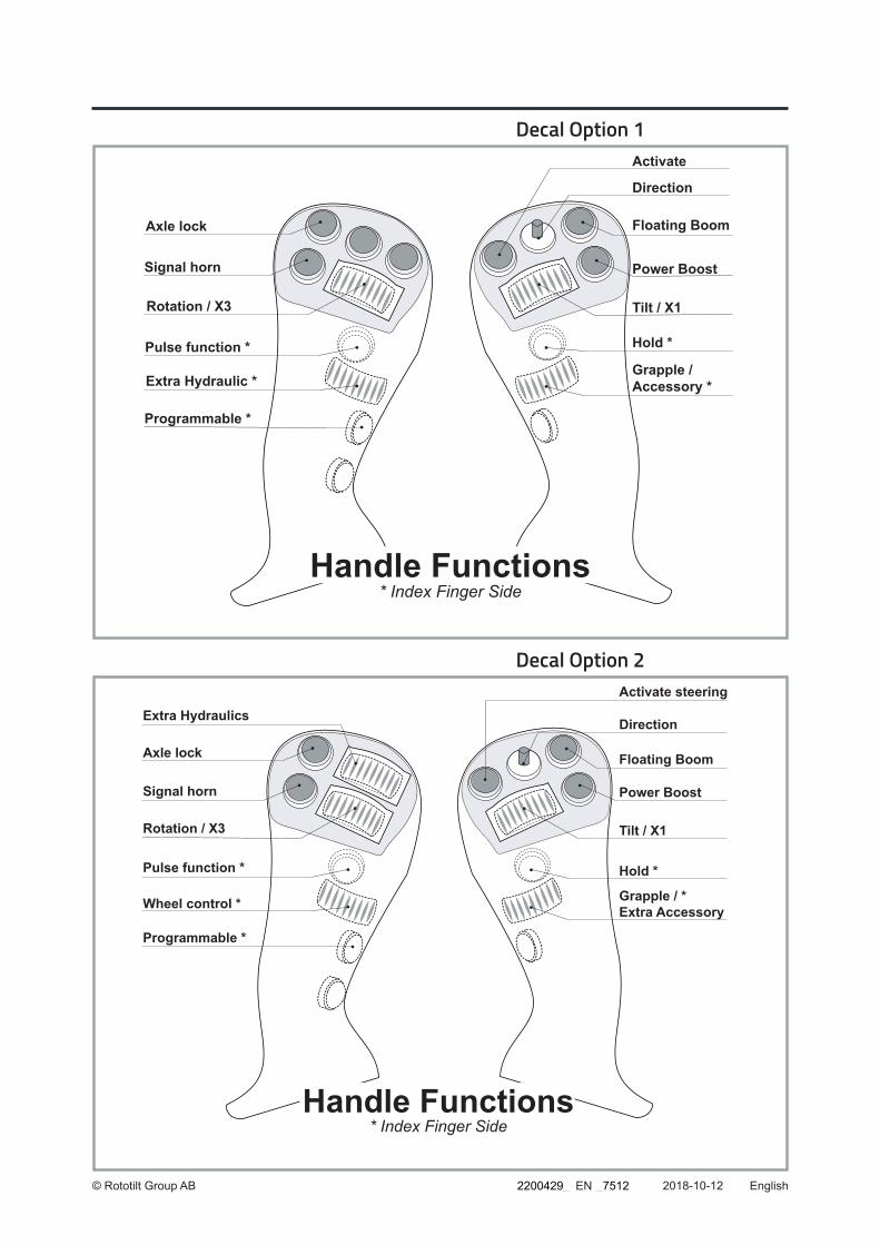
HandlesThe handles are equipped with switches and rollers to control Rototilt® and base machine functions.
The handle functions are configured as described on the sticker.
Also see display & Instructions for Use
!IMPORTANT - The base machine’s factor-installed handles have been replaced with handles adapted for ICS. Carefully check the changed functions, for both the base machine and Rototilt®.
2200429_ _7512
© Rototilt Group AB 2018-10-12
Axle lock
Signal horn
Rotation / X3
Pulse function *
Extra Hydraulic *
Programmable *
Direction
Floating Boom
Power Boost
Tilt / X1
Hold *
Grapple / Accessory *
Activate
Handle Functions* Index Finger Side
Decal Option 1
Extra Hydraulics
Handle Functions* Index Finger Side
Axle lock
Signal horn
Rotation / X3
Pulse function *
Wheel control *
Programmable *
Direction
Floating Boom
Power Boost
Tilt / X1
Hold *
Grapple / *Extra Accessory
Activate steering
Decal Option 2
EN English2200429_ _7512
© Rototilt Group AB 2018-10-09
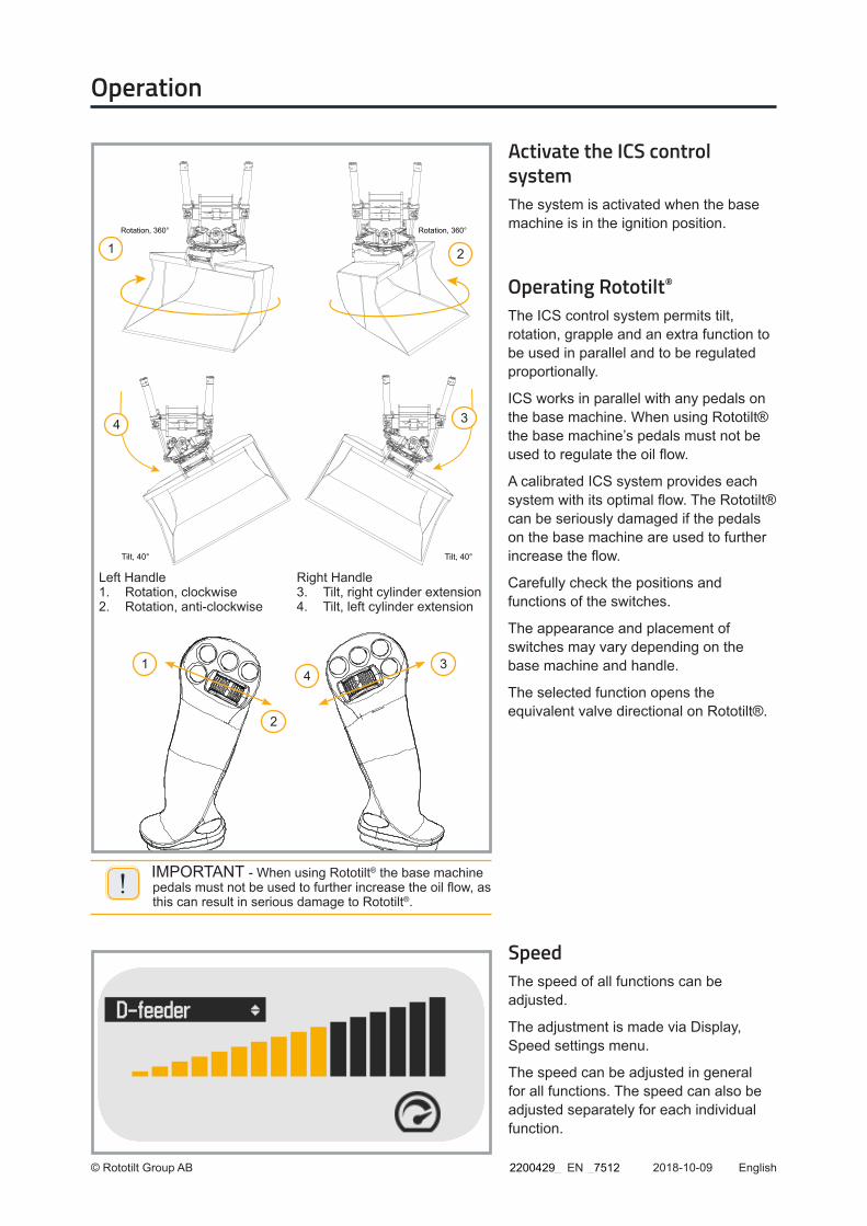
Planeringsskopa, rotation 360°
Rotation, 360° Rotation, 360°
Planeringsskopa, tilt 40°
Tilt, 40°Tilt, 40°
Left Handle1. Rotation, clockwise2. Rotation, anti-clockwise
Right Handle3. Tilt, right cylinder extension4. Tilt, left cylinder extension
4
3
21
4
3
2
1
EN English
!IMPORTANT - When using Rototilt® the base machine pedals must not be used to further increase the oil flow, as this can result in serious damage to Rototilt®.
Operating Rototilt®
The ICS control system permits tilt, rotation, grapple and an extra function to be used in parallel and to be regulated proportionally.
ICS works in parallel with any pedals on the base machine. When using Rototilt® the base machine’s pedals must not be used to regulate the oil flow.
A calibrated ICS system provides each system with its optimal flow. The Rototilt® can be seriously damaged if the pedals on the base machine are used to further increase the flow.
Carefully check the positions and functions of the switches.
The appearance and placement of switches may vary depending on the base machine and handle.
The selected function opens the equivalent valve directional on Rototilt®.
Activate the ICS control systemThe system is activated when the base machine is in the ignition position.
SpeedThe speed of all functions can be adjusted.
The adjustment is made via Display, Speed settings menu.
The speed can be adjusted in general for all functions. The speed can also be adjusted separately for each individual function.
Operation
2200429_ _7512
© Rototilt Group AB 2018-10-09
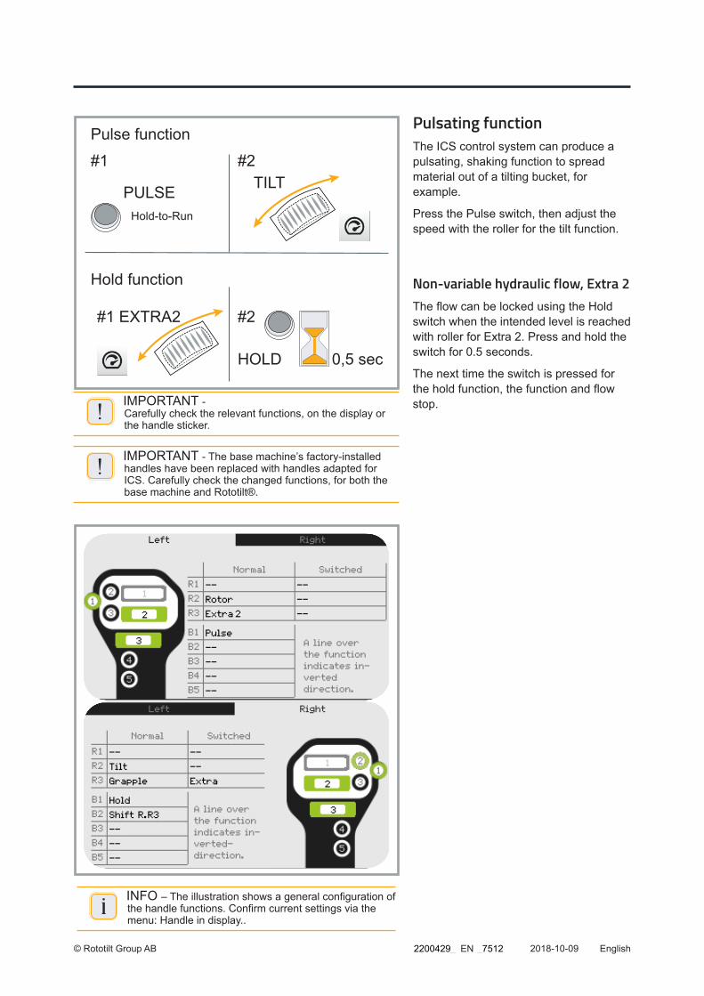
Pulse function
#1 #2TILT
HOLD 0,5 sec
#2EXTRA2#1
Hold function
PULSEHold-to-Run
EN English
Pulsating functionThe ICS control system can produce a pulsating, shaking function to spread material out of a tilting bucket, for example.
Press the Pulse switch, then adjust the speed with the roller for the tilt function.
Non-variable hydraulic flow, Extra 2The flow can be locked using the Hold switch when the intended level is reached with roller for Extra 2. Press and hold the switch for 0.5 seconds.
The next time the switch is pressed for the hold function, the function and flow stop.
!IMPORTANT - The base machine’s factory-installed handles have been replaced with handles adapted for ICS. Carefully check the changed functions, for both the base machine and Rototilt®.
!IMPORTANT - Carefully check the relevant functions, on the display or the handle sticker.
iINFO – The illustration shows a general configuration of the handle functions. Confirm current settings via the menu: Handle in display..
2200429_ _7512
© Rototilt Group AB 2018-10-09EN English
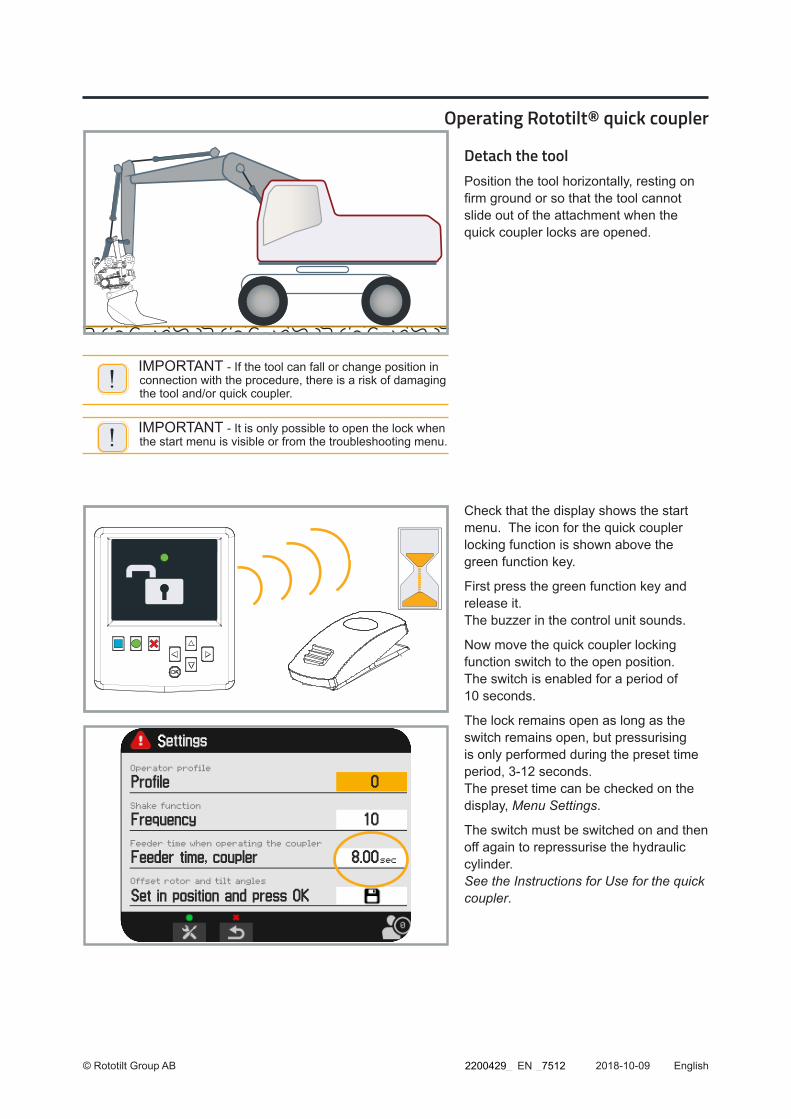
Detach the toolPosition the tool horizontally, resting on firm ground or so that the tool cannot slide out of the attachment when the quick coupler locks are opened.
!IMPORTANT - If the tool can fall or change position in connection with the procedure, there is a risk of damaging the tool and/or quick coupler.
!IMPORTANT - It is only possible to open the lock when the start menu is visible or from the troubleshooting menu.
Operating Rototilt® quick coupler
Check that the display shows the start menu. The icon for the quick coupler locking function is shown above the green function key.
First press the green function key and release it. The buzzer in the control unit sounds.
Now move the quick coupler locking function switch to the open position. The switch is enabled for a period of 10 seconds.
The lock remains open as long as the switch remains open, but pressurising is only performed during the preset time period, 3-12 seconds. The preset time can be checked on the display, Menu Settings.
The switch must be switched on and then off again to repressurise the hydraulic cylinder. See the Instructions for Use for the quick coupler.
2200429_ _7512

© Rototilt Group AB 2018-10-09
Indicator Rod - Open
EN English
When Rototilt® is pressurised hydraulically the quick coupler locking function is opened. The indication on the quick coupler shows that the lock is open.
When the quick coupler’s locking wedge/locking pistons are fully open, the tool can be detached by slowly retracting the bucket cylinder.
Return the switch to its original position to close the lock.
Pressurising is for a preset period of maximum 12 seconds. The default time can be checked on the display, Menu Settings.
The switch must be switched on and then off again to repressurise the hydraulic cylinder.
A warning is shown on the display if the quick coupler is in the open position.
The base machine can be equipped with different combinations of quick coupler and machine coupler. The figure and text on the display are dependent on the combination.
Both the quick coupler and the machine coupler are available with and without electronic monitoring (SecureLock).
2200429_ _7512
© Rototilt Group AB 2018-10-09
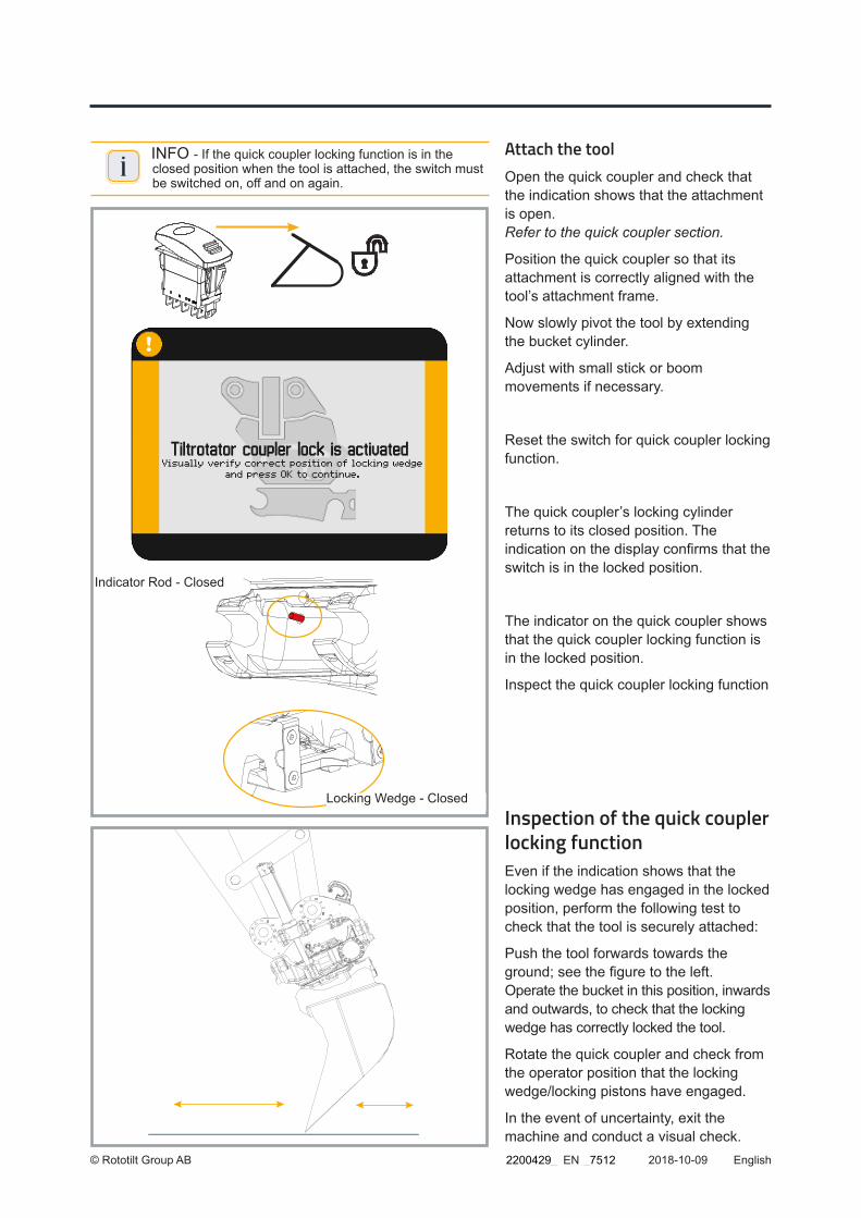
Indicator Rod - Closed
Locking Wedge - Closed
EN English
Attach the toolOpen the quick coupler and check that the indication shows that the attachment is open. Refer to the quick coupler section.
Position the quick coupler so that its attachment is correctly aligned with the tool’s attachment frame.
Now slowly pivot the tool by extending the bucket cylinder.
Adjust with small stick or boom movements if necessary.
Reset the switch for quick coupler locking function.
The quick coupler’s locking cylinder returns to its closed position. The indication on the display confirms that the switch is in the locked position.
The indicator on the quick coupler shows that the quick coupler locking function is in the locked position.
Inspect the quick coupler locking function
iINFO - If the quick coupler locking function is in the closed position when the tool is attached, the switch must be switched on, off and on again.
Inspection of the quick coupler locking functionEven if the indication shows that the locking wedge has engaged in the locked position, perform the following test to check that the tool is securely attached:
Push the tool forwards towards the ground; see the figure to the left. Operate the bucket in this position, inwards and outwards, to check that the locking wedge has correctly locked the tool.
Rotate the quick coupler and check from the operator position that the locking wedge/locking pistons have engaged.
In the event of uncertainty, exit the machine and conduct a visual check.2200429_ _7512

© Rototilt Group AB 2018-10-09
2
1
1 2
3
EN English
Quick coupler with SecureLockOperation in the same way as the quick coupler without SecureLock; see above.
When the quick coupler is opened a warning is given that the locking cylinder has been retracted and is in the open position.
When the quick coupler is closed, the message indicates that the locking cylinder is extended and is in a securely locked position.
Inspect the quick coupler locking function
A warning text appears on the display if the tool is not coupled correctly.
If you do not intend to couple a tool, the warning must be acknowledged.
First press the green function key and release it.
Now press the OK function key. The buzzer warning signal stops.
Return to the start menu using any key.
A visual warning will be shown at 30-second intervals as long as Rototilt® is running without a tool and remains visible until any key is pressed again.
Quick coupler QuickChange™Operation is the same as for the quick coupler; see above.
When the quick coupler is opened a warning is given that the locking pistons have been retracted and are in the open position
When closing the attachment, the first pin (1) is engaged, followed by pin (2) and finally the locking pistons (3).
The quick coupler locking function cannot be closed until both pins in the attach-ment frame are correctly positioned.
The position on the quick coupler’s three sensors are monitored continuously. All sensors are shown in green on the display when a tool is correctly coupled.
Inspect the quick coupler locking function.
2200429_ _7512

© Rototilt Group AB 2018-10-09
1. Remove Rototilt® from Boom Harness
2. Demount Safety Plug
3. Connect Safety Plug to Boom Harness
4. Protect empty connector.
1
2
3
4
EN English
Detach Rototilt®Always park the tiltrotator on a stable and flat surface, without tools. Make sure that Rototilt® cannot tip over.
Disconnect the hydraulic hoses and harness between the Rototilt® and the base machine. The tiltrotator is now detached from the base machine.
If the machine coupler is open while the harness to the tiltrotator is still connected, a warning is shown on the display.
Safety plugThe function is used to lock the machine coupler while the tiltrotator is mounted. The lock prevents accidental opening of the machine coupler.
Disconnect the Rototilt® contact.
Remove the safety plug and connect it to the boom harness contact.
Control of the machine coupler works normally again.
Operating extra hydraulicsDetach Rototilt®. Now select regulation of extra hydraulics on the display by activating double valve block shunt. Confirm with the OK function key.
For return to Rototilt ® control: First connect the tiltrotator and then connect it to the base machine. Now select Rototilt® operation on the display and confirm the selection with the green function key and then the OK function key.
Control of the oil flow in the base machine’s extra hydraulics circuit can be performed using a roller or switch. Both alternatives work in parallel with any pedals on the base machine.
Roller for the tilt function regulates the flow in both directions.
2200429_ _7512

© Rototilt Group AB 2018-10-09
On / Off function
TILT
HOLD 0,5 sec
#2#1
Hold function without tiltrotator
PULSEHold-to-Run
HOLDHold-to-Run
EN English
Non-variable hydraulic flowThe flow can be locked using switch for the hold function when the intended level is reached with roller for the tilt function.
Press and hold the switch for 0.5 seconds.
The next time the switch (Hold) is pressed the function releases and the flow ceases.
On/Off controlSwitch for the pulse function starts and closes full flow in one direction.
Switch for the hold function starts and closes full flow in the other direction.
Activate control with the switch via the Angles menu.
”On/off Double Feeder” must be confirmed with OK.
The function is only active in this view.
2200429_ _7512
© Rototilt Group AB 2018-09-27
C
A
B
10
D
9
11
4
8
3
7
2
6
1
5
EnglishEN
Configuration of ICS
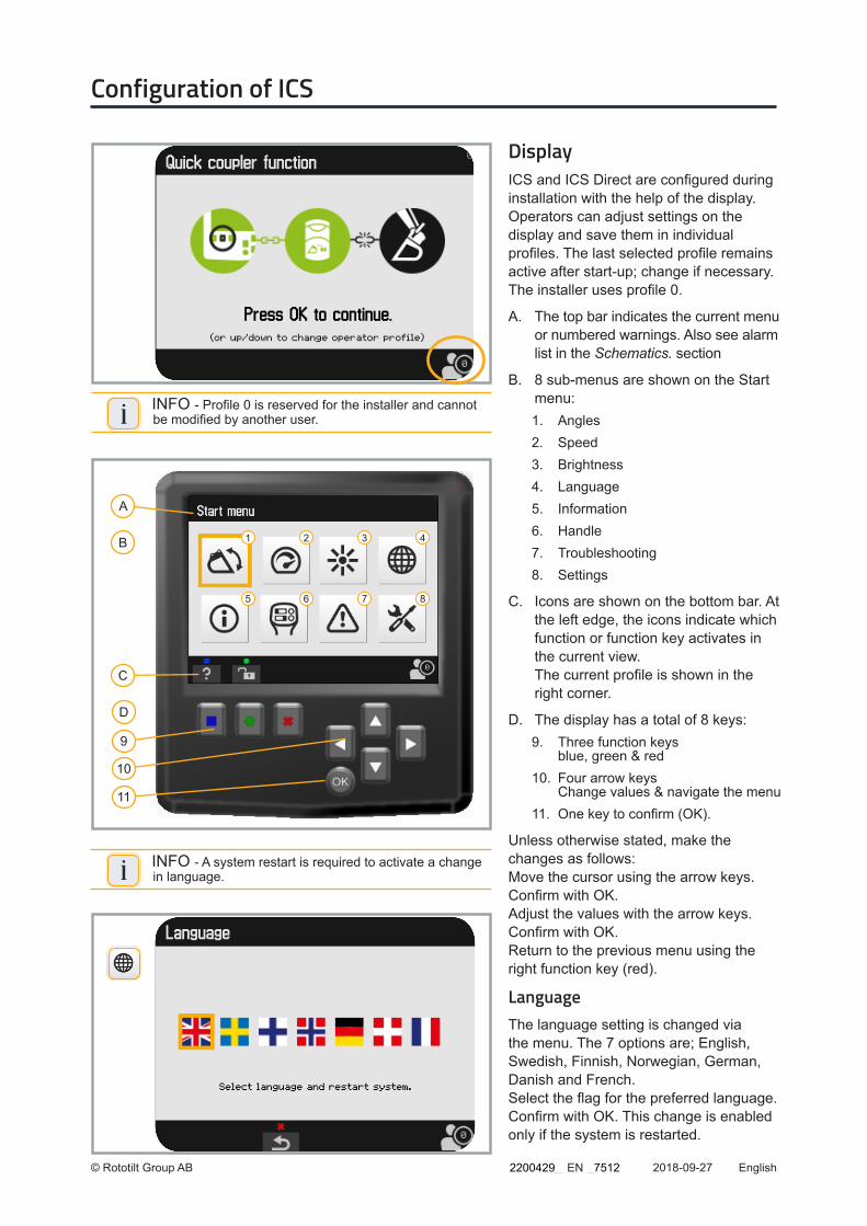
i INFO - Profile 0 is reserved for the installer and cannot be modified by another user.
DisplayICS and ICS Direct are configured during installation with the help of the display. Operators can adjust settings on the display and save them in individual profiles. The last selected profile remains active after start-up; change if necessary. The installer uses profile 0.
A. The top bar indicates the current menu or numbered warnings. Also see alarm list in the Schematics. section
B. 8 sub-menus are shown on the Start menu:1. Angles2. Speed3. Brightness4. Language 5. Information6. Handle7. Troubleshooting8. Settings
C. Icons are shown on the bottom bar. At the left edge, the icons indicate which function or function key activates in the current view. The current profile is shown in the right corner.
D. The display has a total of 8 keys: 9. Three function keys
blue, green & red10. Four arrow keys
Change values & navigate the menu 11. One key to confirm (OK).
Unless otherwise stated, make the changes as follows: Move the cursor using the arrow keys. Confirm with OK. Adjust the values with the arrow keys. Confirm with OK. Return to the previous menu using the right function key (red).
Language The language setting is changed via the menu. The 7 options are; English, Swedish, Finnish, Norwegian, German, Danish and French. Select the flag for the preferred language. Confirm with OK. This change is enabled only if the system is restarted.
i INFO - A system restart is required to activate a change in language.
2200429_ _7512
© Rototilt Group AB 2018-09-27
1
3 2
EnglishEN
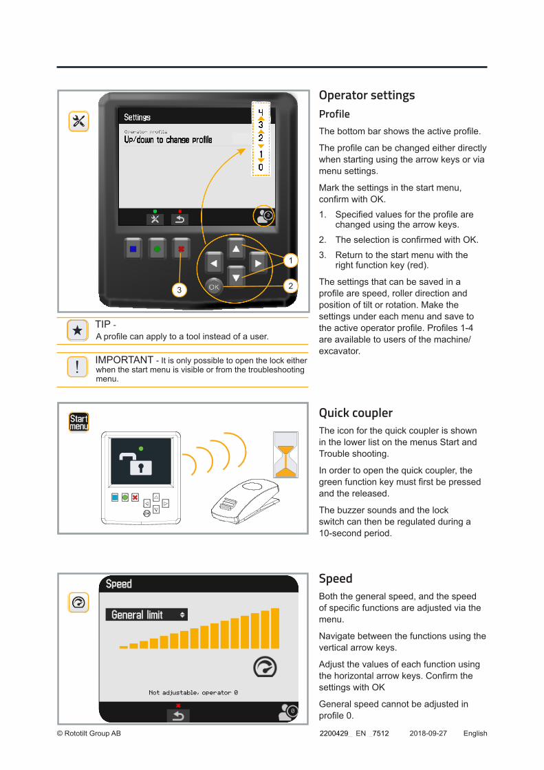
i TIP - A profile can apply to a tool instead of a user.
!IMPORTANT - It is only possible to open the lock either when the start menu is visible or from the troubleshooting menu.
Operator settings Profile The bottom bar shows the active profile.
The profile can be changed either directly when starting using the arrow keys or via menu settings.
Mark the settings in the start menu, confirm with OK.
1. Specified values for the profile are changed using the arrow keys.
2. The selection is confirmed with OK.
3. Return to the start menu with the right function key (red).
The settings that can be saved in a profile are speed, roller direction and position of tilt or rotation. Make the settings under each menu and save to the active operator profile. Profiles 1-4 are available to users of the machine/excavator.
Quick coupler The icon for the quick coupler is shown in the lower list on the menus Start and Trouble shooting.
In order to open the quick coupler, the green function key must first be pressed and the released.
The buzzer sounds and the lock switch can then be regulated during a 10-second period.
Speed Both the general speed, and the speed of specific functions are adjusted via the menu.
Navigate between the functions using the vertical arrow keys.
Adjust the values of each function using the horizontal arrow keys. Confirm the settings with OK
General speed cannot be adjusted in profile 0.
2200429_ _7512
© Rototilt Group AB 2018-09-27 EnglishEN
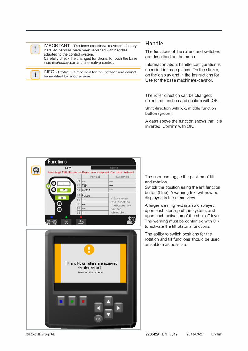
Handle The functions of the rollers and switches are described on the menu.
Information about handle configuration is specified in three places: On the sticker, on the display and in the Instructions for Use for the base machine/excavator.
The roller direction can be changed: select the function and confirm with OK.
Shift direction with x/x, middle function button (green).
A dash above the function shows that it is inverted. Confirm with OK.
!IMPORTANT - The base machine/excavator’s factory-installed handles have been replaced with handles adapted to the control system. Carefully check the changed functions, for both the base machine/excavator and alternative control.
i INFO - Profile 0 is reserved for the installer and cannot be modified by another user.
The user can toggle the position of tilt and rotation. Switch the position using the left function button (blue). A warning text will now be displayed in the menu view.
A larger warning text is also displayed upon each start-up of the system, and upon each activation of the shut-off lever. The warning must be confirmed with OK to activate the tiltrotator’s functions.
The ability to switch positions for the rotation and tilt functions should be used as seldom as possible.
2200429_ _7512
© Rototilt Group AB 2018-09-27 EnglishEN
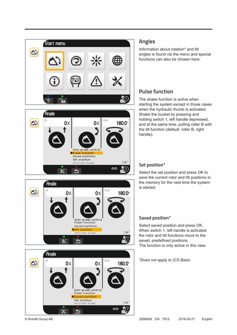
Angles Information about rotation* and tilt angles is found via the menu and special functions can also be chosen here.
Pulse functionThe shake function is active when starting the system except in those cases when the hydraulic thumb is activated. Shake the bucket by pressing and holding switch 1, left handle depressed, and at the same time, pulling roller B with the tilt function (default: roller B, right handle).
Set position*Select the set position and press OK to save the current rotor and tilt positions in the memory for the next time the system is started.
Saved position*Select saved position and press OK. When switch 1, left handle is activated the rotor and tilt functions move to the saved, predefined positions. The function is only active in this view.
*Does not apply to ICS Basic.
2200429_ _7512
© Rototilt Group AB 2018-09-27
Parked position
Active hydraulic thumb
EnglishEN
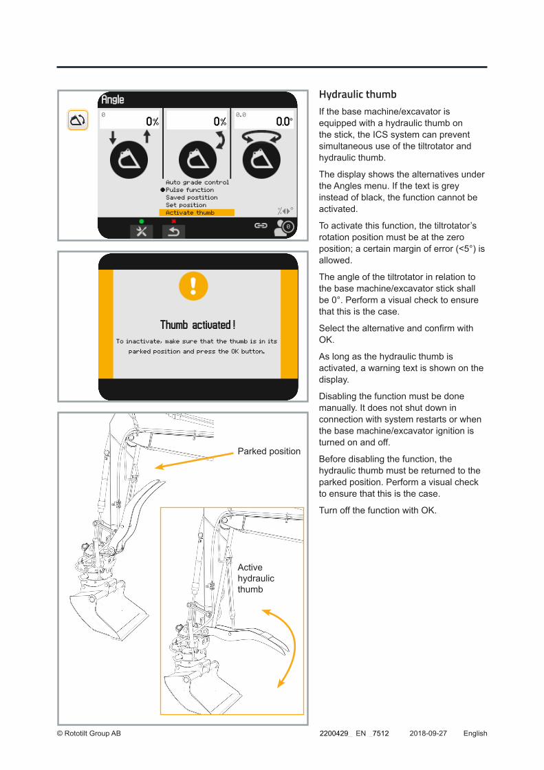
Hydraulic thumbIf the base machine/excavator is equipped with a hydraulic thumb on the stick, the ICS system can prevent simultaneous use of the tiltrotator and hydraulic thumb.
The display shows the alternatives under the Angles menu. If the text is grey instead of black, the function cannot be activated.
To activate this function, the tiltrotator’s rotation position must be at the zero position; a certain margin of error (<5°) is allowed.
The angle of the tiltrotator in relation to the base machine/excavator stick shall be 0°. Perform a visual check to ensure that this is the case.
Select the alternative and confirm with OK.
As long as the hydraulic thumb is activated, a warning text is shown on the display.
Disabling the function must be done manually. It does not shut down in connection with system restarts or when the base machine/excavator ignition is turned on and off.
Before disabling the function, the hydraulic thumb must be returned to the parked position. Perform a visual check to ensure that this is the case.
Turn off the function with OK.
2200429_ _7512

© Rototilt Group AB 2018-09-27
** Not visible for operator when RPS is installed. Visas ej i förarprofil om RPS är installerat.
EnglishEN
Automatic Grade ControlOption only available with activated RPS and established communication with excavator system.
If the automatic tilt and rotation function is included in the installed excavation system, it can be controlled via ICS.
Select the icon for the Angles menu and then confirm your selection with OK.
Select Auto grade control (AGC) in the view on the display using the arrow keys.
Confirm your choice with OK.
Activate the function by pressing and holding the button on the handle. This is generally located on the right handle; check against the handle sticker.
The function is only active in this view.
Shake function/FrequencySelect Frequency and adjust the frequency of the shake function.
PressurisingSelect Feeder time Coupler and set the required value (3-12 sec). The saved value regulates the time that the quick coupler locking function is pressurised.
Calibrate anglesIn order for the angle display to work correctly, it must be calibrated with the right bucket.
Rotate the bucket to the zero position. Position the bucket bottom flat against the surface.
Now highlight the icon to save (diskette), using the arrow keys. Confirm with the OK function key.
i INFO - If RPS is installed, angles are calibrated by an authorised installation engineer.
2200429_ _7512

© Rototilt Group AB 2018-09-27
Serial number 000655360Program version, Cabin Rototilt 11.222.333Program version, Display Rototilt 11.222.333Program version, Tiltrotator 01.002.003Supply voltage Cab 0.0V Tiltrotator 0.0VTime 12:42Date 2016-10-01Hours counters Power on 0:08 Rotor 0:00 Tilt 0:00 Grapple 0:00 Extra2 0:00
EnglishEN
Double feeder The Double feeder mode can be activated after Rototilt® has been disengaged.
The function is either controlled with roller for the tilt function or switches for the pulse function and hold function.
Activate control with the switch via the Angles menu.
”On/off Double Feeder” must be confirmed with OK.
The function is only active in this view.
See Operation of extra hydraulics.
System InformationSerial number - The tiltrotator’s specific number, also found on the rating plate.
Software version - Shows the version number for the software of each unit, display, CCI and TCU.
Supply Voltage - Power supply to the control unit and tiltrotator.
Time - Current time. Select the row and then press the middle function button (green) to set the time. In some cases Bat Clock is not connected, which results in the system losing the time and date setting.
Date - Current date.
Hours counters - Shows the total hours of operation for the tiltrotator, and the total hours of operation for each function.
2200429_ _7512

© Rototilt Group AB 2018-09-27 EnglishEN
!IMPORTANT - Detailed information about the measures to be performed at each interval can be found in the instructions for the tiltrotator. Interval: “Daily inspection” and “8th hour of operating” refer to different service points.
Brightness The display brightness is adjusted with the arrow keys.
Confirm with OK.
Reminder service The system shows a reminder, after every 8 hours of operation. The reminder indicates that requisite service must be carried out.
If the ILS option is specified, the reminder for the 8-hour interval is automatically switched off. See the Rototilt® Instructions for Use.
The system also shows reminders for ther intervals.
See the Rototilt® Instructions for Use
2200429_ _7512

© Rototilt Group AB 2018-09-27
Forward
Backward Confirm
EnglishEN
TroubleshootingThe menu has three levels: Current alarm, Historical alarm and Alarm log.
Press the middle function button (green) to move through the levels. Use the right function button (red) to go back.
Detailed information: Select current alarm Confirm with OK. The information is displayed in display.
Troubleshooting ICS
Historical alarms Previous alarms can be read on the historical alarms submenu. The operator can delete this list. Press the left function key (blue) to delete.
Alarm logAll alarms are also saved in a log. This entries cannot be deleted.
Active alarmsCan be shown on the display either with a complete picture or as text on the upper bar.
The numbering of alarms on the upper bar is the same regardless of language.
Go to the Troubleshooting menu for detailed information.
2200429_ _7512
© Rototilt Group AB 2018-09-27 EnglishEN
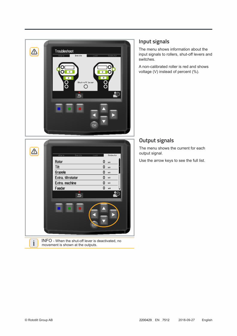
Input signalsThe menu shows information about the input signals to rollers, shut-off levers and switches.
A non-calibrated roller is red and shows voltage (V) instead of percent (%).
Output signalsThe menu shows the current for each output signal.
Use the arrow keys to see the full list.
i INFO - When the shut-off lever is deactivated, no movement is shown at the outputs.
2200429_ _7512

© Rototilt Group AB 2018-09-27
1
2
3
EnglishEN
Quick coupler locking function The menu shows information about input and output signals to the lock circuit.
It is possible to activate the lock using the middle function key (green). Also refer to “Detach the tool” in the Instructions for Use.
When the lock switch is active the two upper circles are green.
When the valve solenoids are active the two lower circles are green.
The location of the locking wedge is shown with a black bar against a red-green-yellow scale.
1. Coupler Sensor concerns the quick coupler’s locking wedge.
2. Coupler Sensor, RAC concerns the machine coupler/quick coupler (excavator) locking wedge.
3. If the tiltrotator is equipped with the option QuickChange™, the quick coupler is shown with an alternative icon; see Coupler Sensor.
Troubleshooting of machine coupler
Communications errorThe message RAC offline indicates a communications error on the CAN bus. The warning is shown both for errors on the CAN bus and in event of a power failure.
Sensor failureThe message indicates a sensor error in the machine coupler/quick coupler (excavator).
The value of the current voltage is helpful when troubleshooting. Values close to 0 V indicate a short-circuit to earth. Values close to 5 V indicate a short-circuit to the supply.
Detailed troubleshooting of machine coupler/quick coupler (excavator); see the Instructions for Use for the machine coupler.2200429_ _7512
© Rototilt Group AB 2018-09-27
2
3
1
EnglishEN
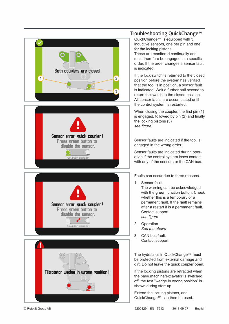
Troubleshooting QuickChange™QuickChange™ is equipped with 3 inductive sensors, one per pin and one for the locking pistons. These are monitored continually and must therefore be engaged in a specific order. If the order changes a sensor fault is indicated.
If the lock switch is returned to the closed position before the system has verified that the tool is in position, a sensor fault is indicated. Wait a further half second to return the switch to the closed position. All sensor faults are accumulated until the control system is restarted.
When closing the coupler, the first pin (1) is engaged, followed by pin (2) and finally the locking pistons (3) see figure.
Sensor faults are indicated if the tool is engaged in the wrong order.
Sensor faults are indicated during oper-ation if the control system loses contact with any of the sensors or the CAN bus.
Faults can occur due to three reasons.
1. Sensor fault. The warning can be acknowledged with the green function button. Check whether this is a temporary or a permanent fault. If the fault remains after a restart it is a permanent fault. Contact support. see figure
2. Operation. See the above
3. CAN bus fault. Contact support
The hydraulics in QuickChange™ must be protected from external damage and dirt. Do not leave the quick coupler open.
If the locking pistons are retracted when the base machine/excavator is switched off, the text ”wedge in wrong position” is shown during start-up.
Extend the locking pistons, and QuickChange™ can then be used.
2200429_ _7512
© Rototilt Group AB 2018-10-12 schema:1
Schematics and Overwievs for hydraulic as well as electrical systems, in the following pages are meant to serve mainly as a guide for Troubleshooting.
! WARNING! More extensive adjustments and repairs must be done by an authorized service workshop.
Schematics
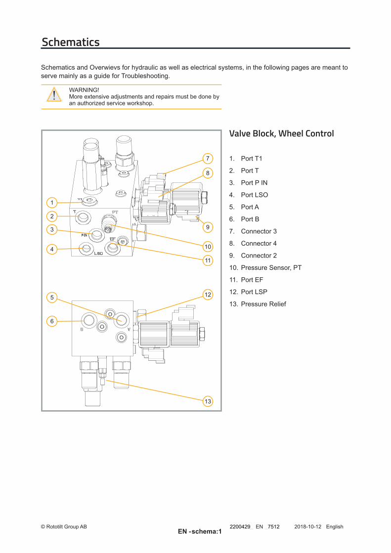
Valve Block, Wheel Control
1. Port T1
2. Port T
3. Port P IN
4. Port LSO
5. Port A
6. Port B
7. Connector 3
8. Connector 4
9. Connector 2
10. Pressure Sensor, PT
11. Port EF
12. Port LSP
13. Pressure Relief
9
125
7
8
10
11
1
2
3
4
6
13
EnglishENEN -
2200429_ _7512

© Rototilt Group AB 2018-10-12 schema:2
Valveblock, Wheel Control - Open Center
EnglishENEN -
2200429_ _7512
© Rototilt Group AB 2018-10-12 schema:3
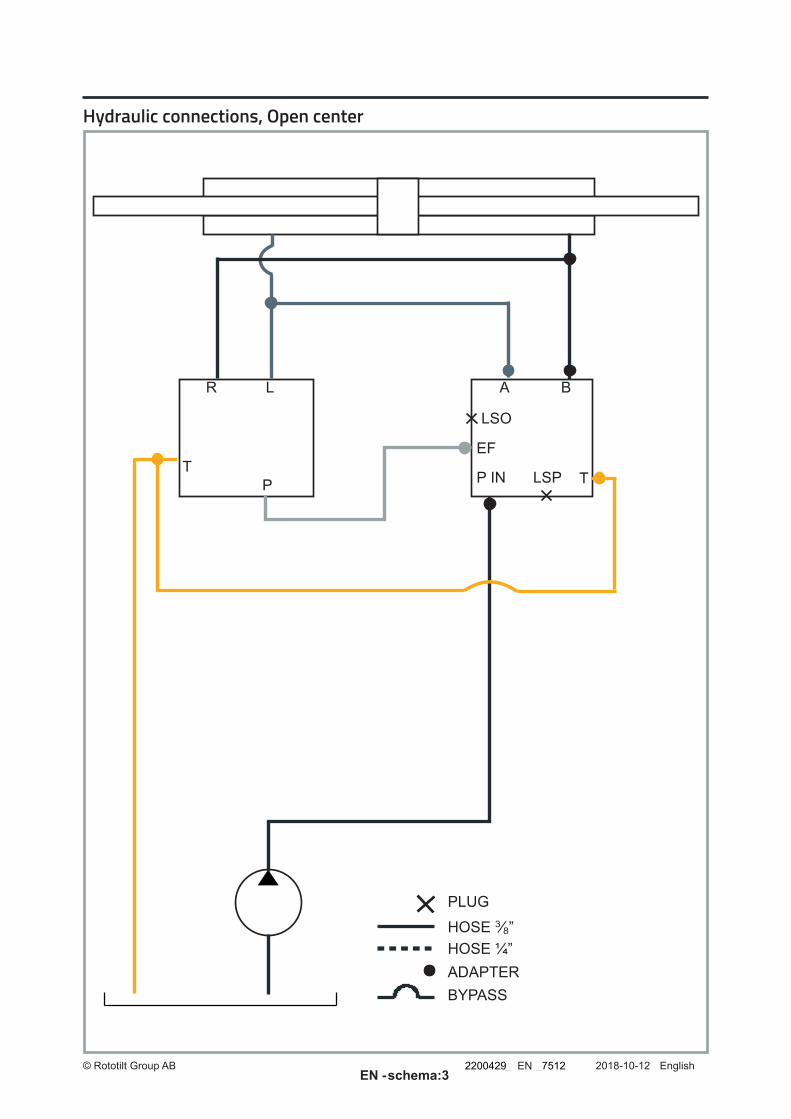
LSO
LSP
EFT
TP P IN
A BR L
ADAPTER
HOSE 3⁄8”HOSE ¼”
BYPASS
PLUG
Hydraulic connections, Open center
EnglishENEN -
2200429_ _7512
© Rototilt Group AB 2018-10-12 schema:4
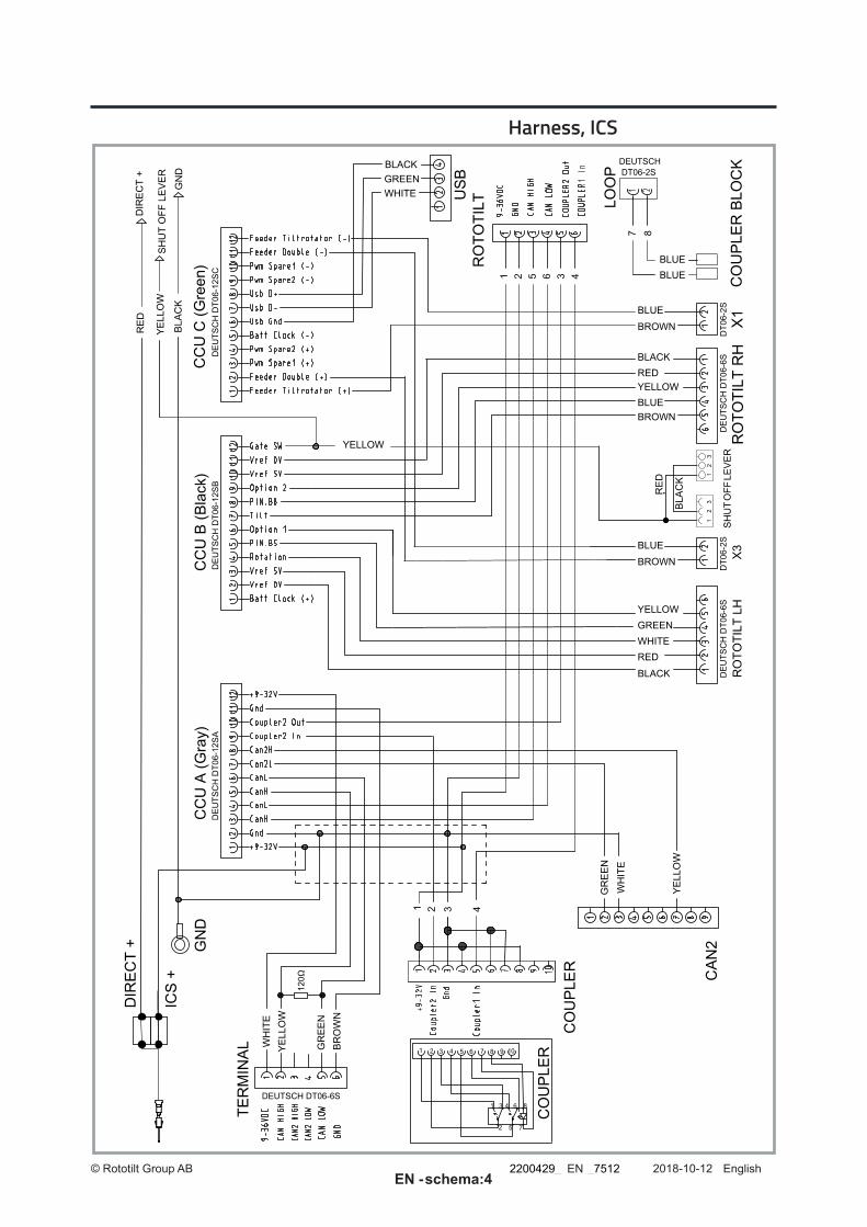
120Ω
Harness, ICS
EnglishENEN -
2200429_ _7512

© Rototilt Group AB 2018-10-12 schema:5
Harness, ICS Direct
EnglishENEN -
2200429_ _7512

© Rototilt Group AB 2018-10-12 schema:6
8 7 4 3 6 5 2 1
Harness Boom
5-pi
nned
conn
ecto
r K
eep
conn
ecto
r plu
gged
and
cla
mp
to a
ppro
pria
te h
arne
ss to
kee
p fro
m d
amag
e.W
hen
appl
icab
le; R
emov
e pl
ug a
nd c
onne
ct to
cor
resp
ondi
ng c
onne
ctor
for M
achi
ne C
oupl
er
with
opt
ion
Sec
ure
Lock
.
EnglishENEN -
2200429_ _7512
© Rototilt Group AB 2018-10-12 schema:7
3
2
54
1
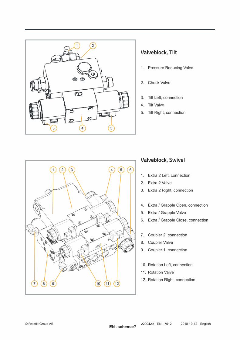
Valveblock, Tilt
1. Pressure Reducing Valve
2. Check Valve
3. Tilt Left, connection
4. Tilt Valve
5. Tilt Right, connection
Valveblock, Swivel
1. Extra 2 Left, connection
2. Extra 2 Valve
3. Extra 2 Right, connection
4. Extra / Grapple Open, connection
5. Extra / Grapple Valve
6. Extra / Grapple Close, connection
7. Coupler 2, connection
8. Coupler Valve
9. Coupler 1, connection
10. Rotation Left, connection
11. Rotation Valve
12. Rotation Right, connection
1 2 3 4 5 6
7 8 9 10 11 12
EnglishENEN -
2200429_ _7512

© Rototilt Group AB 2018-10-12 schema:8
!For optimum performance and service life, return T1 must be connected to free return.
To enable complete drainage via Drain, a separate return must be connected to
the tank via T4.
Hydraulics Schematic ICS & ICS Q Rototilt® R4, R5, R6, R8
EnglishENEN -
2200429_ _7512

© Rototilt Group AB 2018-10-12 schema:9
Only with secure lock
Harness C Rototilt® R3 - R8
Harness B Rototilt® R3 - R8
EnglishENEN -
2200429_ _7512

© Rototilt Group AB 2018-10-12 schema:10
5
6
Harness A option oilquick
Harness A Rototilt R2-R8
CAN J1939
EnglishENEN -
2200429_ _7512

© Rototilt Group AB 2018-10-12 schema:11
3
LED lamp
Locking cylinder sensor
Electric swivel oilquick RT -unit
8 wires
Grey
Grey
Yellow
Green
Yellow
Green
Brown
WhiteBrown
White
Electric swivel
7 wires
LED lamp
Locking cylinder sensor
Secure Lock only: Each el.swivel have a number of wires available for optional connection. Cituated inside heat shrink tubing. Max 2 Amp per wire. See arrows in illustrations below
BLACKBROWNBLUEWHITE
BROWNBLUEWHITE
9 wires
Electric swivel M12
EnglishENEN -
2200429_ _7512

System error
Error message: Possible causes Remedial action
100 Software not started SW. Missing, possible Can failure Check CAN bus circuit.
101 No contact with Cabin unit CAN bus failure Check CAN bus circuit if orange led gives pulsating light. If no leds are on , check PWR harness.
102 Wrong software in display Mismatch between software in display/ CCU or unable to verify that software in display/CCU are matching.
Check Info for differences in software versionCheck CAN bus circuit.
110 Internal error Software error, firmware mismatch. Will only show up in error log.
Contact the service workshop.
111 Output error Error detected on output, most likely shortcut on digital output.
Check harness on indicated output
112 V-SYS error Input voltage too low/high, check system voltage on machine.
Check harness for power supply if low, check alternator if high.
113 V-OUT error N/A
114 Temp error. Internal temperature too low/high (TCU).
115 VREF-OUT error Error detected on 5V-output to rollers and sensor’s.
Check 5V reference supply wires in harness to affected function
116 VCC error Error detected on internal voltage. Contact the service workshop.
117 VSS error
118 VDD error
119 HW error Internal hardware error, most likely inclinometer.
Contact the service workshop.
121 Slave unit disconnected Lost connection to slave unit, for example expansion unit.
Check CAN bus circuit.
Overview - Alarm List
Application errorError message: Possible causes Remedial action
For more detailed information regarding the alarms below, consult the alarmlist in the display.1 Sensor circuit error, coupler! Input signal fault from the coupler sensor. Check the harness in terms of crush damage or open
circuit. Check the sensor/ electrical swivel Contact the service workshop.
2 Service 8h, 40h, 160h, 500h Service Refer to Instructions of Use Perform service according to Instruction of Use and confirm.
3 Error coupler circ.1Error coupler circ. 2
Error in output signal coupler 2=CCU 1=TCU Check the harness in terms of crush damage or open circuit. Contact the service workshop.
4 Wedge not in position! Quick coupler not closed Check the wedge, Refer to Instructions of Use
5 Wedge past position! No tool attached If correct: press OK, Refer to Instructions of Use
6 Coupler switch circuit defect! Input signal to TCU and CCU not synchronized Check the coupler switch harness in terms of crush damage or open circuit. Contact the service workshop.
7 Quick coupler open! If quick coupler not opened check wedge
8 Roller outside range! Voltage from roller outside range (0,5-4,5V). Cable breakage, connector play or roller fault.
Check the harness to the joystick in terms of crush damage or open circuit. Restart the system. Contact the service workshop.
9 Power output, feeder! Error in output signal from CCU to feeder valve. Cable breakage or electric coil fault. Also valid for 0-5 Volt machine control aplications.
Check the harness in terms of crush damage or open circuit. Check the condition of the valve. Return the roller to the zero position.Machine controll applications: Check PWM to analog module, connectors and harness Contact the service workshop.
© Rototilt Group AB 2018-08-10 Alarm:1
EnglishENEN -
2200429_ _7512
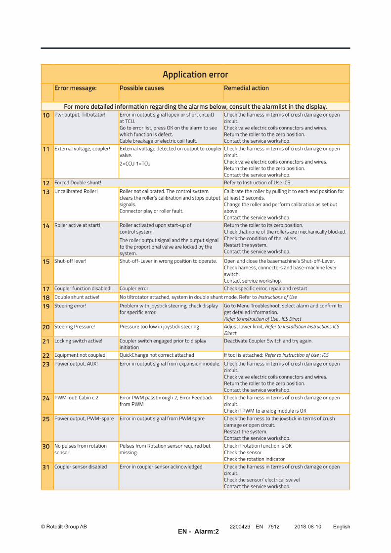
Application errorError message: Possible causes Remedial action
For more detailed information regarding the alarms below, consult the alarmlist in the display.10 Pwr output, Tiltrotator! Error in output signal (open or short circuit)
at TCU. Go to error list, press OK on the alarm to see which function is defect. Cable breakage or electric coil fault.
Check the harness in terms of crush damage or open circuit. Check valve electric coils connectors and wires. Return the roller to the zero position. Contact the service workshop.
11 External voltage, coupler! External voltage detected on output to coupler valve. 2=CCU 1=TCU
Check the harness in terms of crush damage or open circuit. Check valve electric coils connectors and wires. Return the roller to the zero position. Contact the service workshop.
12 Forced Double shunt! Refer to Instruction of Use ICS
13 Uncalibrated Roller! Roller not calibrated. The control system clears the roller’s calibration and stops output signals. Connector play or roller fault.
Calibrate the roller by pulling it to each end position for at least 3 seconds. Change the roller and perform calibration as set out above Contact the service workshop.
14 Roller active at start! Roller activated upon start-up of control system. The roller output signal and the output signal to the proportional valve are locked by the system.
Return the roller to its zero position. Check that none of the rollers are mechanically blocked. Check the condition of the rollers. Restart the system. Contact the service workshop.
15 Shut-off lever! Shut-off-Lever in wrong position to operate. Open and close the basemachine’s Shut-off-Lever. Check harness, connectors and base-machine lever switch. Contact service workshop.
17 Coupler function disabled! Coupler error Check specific error, repair and restart
18 Double shunt active! No tiltrotator attached, system in double shunt mode. Refer to Instructions of Use
19 Steering error! Problem with joystick steering, check display for specific error.
Go to Menu Troubleshoot, select alarm and confirm to get detailed information. Refer to Instruction of Use : ICS Direct
20 Steering Pressure! Pressure too low in joystick steering Adjust lower limit, Refer to Installation Instructions ICS Direct
21 Locking switch active! Coupler switch engaged prior to display initiation
Deactivate Coupler Switch and try again.
22 Equipment not coupled! QuickChange not correct attached If tool is attached: Refer to Instruction of Use : ICS
23 Power output, AUX! Error in output signal from expansion module. Check the harness in terms of crush damage or open circuit. Check valve electric coils connectors and wires. Return the roller to the zero position. Contact the service workshop.
24 PWM-out! Cabin c.2 Error PWM passthrough 2, Error Feedback from PWM
Check the harness in terms of crush damage or open circuit. Check if PWM to analog module is OK
25 Power output, PWM-spare Error in output signal from PWM spare Check the harness to the joystick in terms of crush damage or open circuit. Restart the system. Contact the service workshop.
30 No pulses from rotation sensor!
Pulses from Rotation sensor required but missing.
Check if rotation function is OK Check the sensor Check the rotation indicator
31 Coupler sensor disabled Error in coupler sensor acknowledged Check the harness in terms of crush damage or open circuit. Check the sensor/ electrical swivel Contact the service workshop.
© Rototilt Group AB 2018-08-10 Alarm:2
EnglishENEN -
2200429_ _7512


![TCU/RCU RF Head Control Units - Elber S.r.l.UserManuals~TCU_RCU-Series_[EN].pdf · TCU/RCU Analogue Page 3 of 35 Version 2.2 2 General Description. The TCU and RCU are the control](https://img.pdfslide.us/doc/110x75/5c05706a09d3f2da2e8b483d/tcurcu-rf-head-control-units-elber-srl-usermanualstcurcu-seriesenpdf.jpg)