Embed Size (px)
Citation preview
International Research Journal of Engineering and Technology (IRJET) e-ISSN: 2395-0056
Volume: 04 Issue: 10 | Oct -2017 www.irjet.net p-ISSN: 2395-0072
© 2017, IRJET | Impact Factor value: 5.181 | ISO 9001:2008 Certified Journal | Page 600
Control Strategy of triple Effect Evaporators Based on Solar Desalination of Red Sea water
Tayseir .M. Ahmed (1), Gurashi .A Gasmelseed(2)
1Karray University, Sudan 2 University of Science and Technology ,P .o Box 30, Omdurman, Sudan
---------------------------------------------------------------------***---------------------------------------------------------------------ABSTRACT: Multiple effect evaporator control is a problems that has been widely reported in desalination unit. Evaporators are the largest heat users and major contributors to losses in desalination factories .These factors make effective evaporator control crucial to overall factory efficiency. Desalination unit has many parameterizes to control, the most important are temperature of the evaporator ,the level and flow rate of the red sea water, and concentrate of brine. The control strategy was developed and the transfer functions were identified .From these functions the characteristic equation .Were calculated as well as the open-loop transfer functions Routh, direct ,Root-locus and bode methods were used for tuning ,stability analyses and simulation response of the system. Key Words Control Strategy, Solar Desalination; Red Sea Water ,triple evaporator 1. Introduction: Multiple effect evaporator, one of the main methods used for the concentration of aqueous solution ,refers to the production of the salt and desalinate water from red sea water by boiling the liquor in a suitable vessel Evaporation. Evaporation is carried out by adding heat to solution to vaporize the solvent .The heat is supplied principally to provide the latent heat of vaporization ,and ,by adopting methods for recovery of heat from the vapor ,it has been possible to achieve great economy in heat utilization .Whilst the normal heating medium is generally low pressure exhaust steam from turbines ,special heat transfer fluids or flue gases may be used .The control of an evaporation unit require the transfer functions were identified. 2. .System Stability: The stability of the control system is very important and almost should be checked using different methods .The stability of system deepens on the location of the roots of the characteristic equation on argand diagram .The roots are determined by direct substitution ,bode diagram ,root locus and nyquist plot .The stability of the system are also determined by Routh criterion which has special technique to show if the system critical stable ,stable or unstable from these methods the adjustable parameters can be obtained using Zeigler-Nichols technique[1].
3. System Stability methods:- 3.1 Routh-Hurwitz criterion: Apply the Routh test on the closed –loop characteristic polynomial to find if there are closed –loop poles on the right-hand –plane. Evaluated the establish limits on the controller gain .If the characteristic polynomial passes the coefficient test, we then construct the Routh array to find the necessary and sufficient condition for stability .This is one of the few classical techniques that we do not emphasize and the general formula is omitted .The array construction up to a fourth order polynomial is used to illustrate the concept. Generally, for an n-th order polynomial, we need (n+1) rows the first two rows are filled in with the coefficients of the polynomial in a column. of positive poles[2]. 3.2 Direct substitution: Substitutes s=іω in characteristic polynomial and solve for closed –loop poles on Im-axis. Evaluated the ultimate gain
and ultimate period ( ) [2].
3.3 Ziegler-Nichols ultimate-cycle method: This empirical method is based on closed-loop testing (also called on –line tuning) of processes which are inherently stable, but where the system may become unstable. We use only proportional control in the experiment. If it is not possible to disable the integral and derivative control modes, we set the integral time to its maximum value and the derivative time to its minimum .The proportional gain is slowly increased until the system begins to exhibit sustained oscillations with a give small step set point or load change. The proportional gain and period of oscillation at this point are ultimate gain, Ku, and ultimate period, Tu. These two quantities are used in a set of empirical tuning relation developed by Ziegler and Nichols[2]. 3.4 Root -locus: -The root-locus is the plots,, in complex plane, of the roots of the OLTF. -They are very useful to determine the stability of the closed-loop system as the gain K changes[2].
International Research Journal of Engineering and Technology (IRJET) e-ISSN: 2395-0056
Volume: 04 Issue: 10 | Oct -2017 www.irjet.net p-ISSN: 2395-0072
© 2017, IRJET | Impact Factor value: 5.181 | ISO 9001:2008 Certified Journal | Page 601
3.5 Bode Method: Bode plot is drawn for the secondary loop to calculate the ultimate gain and ultimate period, then the ultimate gain for primary loop is calculated from the secondary loop[2]. 4.Time Response: The time response represents how the state of a dynamic system changes in time when subjected to a particular input since the models has been derived of differential equation ,some integration must be performed in order to determine the time response of the system . fortunately ,MATLAB provides many useful resources for calculating time responses for many types of inputs. MATLAB provides tools for automatically choosing optimal PID gains[3]. 5. MATLAB Software: MATLAB is integrated technical computing environment that combines numeric computation, and visualization, and a high level programming language. The MATLAB software was originally developed to a matrix laboratory .Its capabilities have expanded greatly in recent years and today it is a leading tool for engineering concepts in mathematics. Being able to plot mathematical functions and data MATLAB, can be used in research, development and in industry. It is used in this research for tuning through different tuning techniques[4].
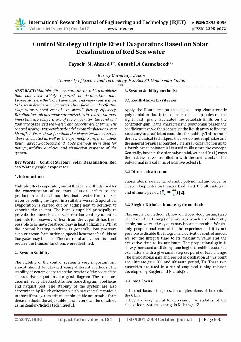
Fig (1) : Control Strategy and loops formation
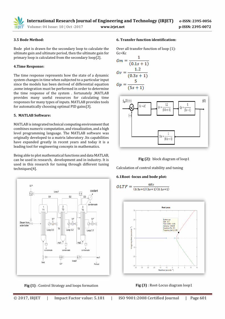
6. Transfer function identification: Over all transfer function of loop (1): Gc=Kc
Fig (2): block diagram of loop1 Calculation of control stability and tuning 6.1Root -locus and bode plot:
Fig (3) : Root-Locus diagram loop1
International Research Journal of Engineering and Technology (IRJET) e-ISSN: 2395-0056
Volume: 04 Issue: 10 | Oct -2017 www.irjet.net p-ISSN: 2395-0072
© 2017, IRJET | Impact Factor value: 5.181 | ISO 9001:2008 Certified Journal | Page 602
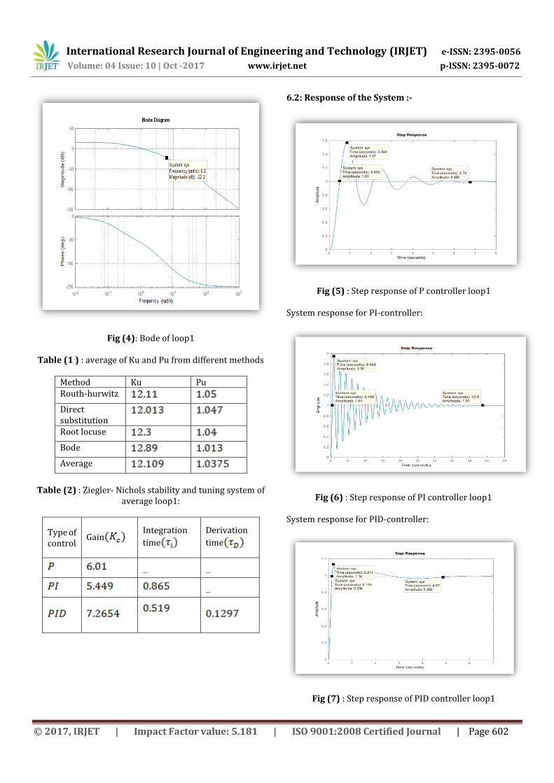
Fig (4): Bode of loop1 Table (1 ) : average of Ku and Pu from different methods
Method Ku Pu Routh-hurwitz
Direct substitution
Root locuse
Bode
Average
Table (2) : Ziegler- Nichols stability and tuning system of
average loop1:
Derivation
time
Integration
time Gain
Type of control
_ _
_
6.2: Response of the System :-
Fig (5) : Step response of P controller loop1 System response for PI-controller:
Fig (6) : Step response of PI controller loop1 System response for PID-controller:
Fig (7) : Step response of PID controller loop1
International Research Journal of Engineering and Technology (IRJET) e-ISSN: 2395-0056
Volume: 04 Issue: 10 | Oct -2017 www.irjet.net p-ISSN: 2395-0072
© 2017, IRJET | Impact Factor value: 5.181 | ISO 9001:2008 Certified Journal | Page 603
Table (3) : Simulation Parameters of loop1for P,PI and PID
Controller type
Over shoot
Setting time
Rise time
Decay ratio
P 1.57 6.76 0.495 2.496 PI 1.95 43.8 0.488 3.803 PID 1.14 4.87 0.145 1.2996
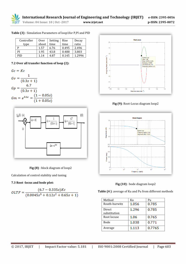
7.2 Over all transfer function of loop (2):
Fig (8) : block diagram of loop2 Calculation of control stability and tuning 7.3 Root -locus and bode plot:
Fig (9): Root-Locus diagram loop2
Fig (10) : bode diagram loop2
Table (4 ) :average of Ku and Pu from different methods
Method Ku Pu Routh-hurwitz
Direct substitution
Root locuse
Bode
Average
International Research Journal of Engineering and Technology (IRJET) e-ISSN: 2395-0056
Volume: 04 Issue: 10 | Oct -2017 www.irjet.net p-ISSN: 2395-0072
© 2017, IRJET | Impact Factor value: 5.181 | ISO 9001:2008 Certified Journal | Page 604
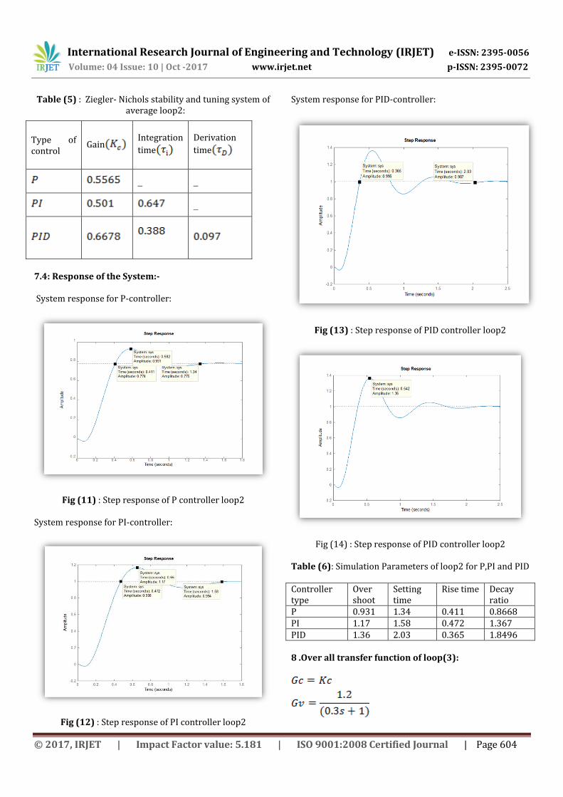
Table (5) : Ziegler- Nichols stability and tuning system of average loop2:
7.4: Response of the System:- System response for P-controller:
Fig (11) : Step response of P controller loop2 System response for PI-controller:
Fig (12) : Step response of PI controller loop2
System response for PID-controller:
Fig (13) : Step response of PID controller loop2
Fig (14) : Step response of PID controller loop2 Table (6): Simulation Parameters of loop2 for P,PI and PID Controller type
Over shoot
Setting time
Rise time Decay ratio
P 0.931 1.34 0.411 0.8668 PI 1.17 1.58 0.472 1.367 PID 1.36 2.03 0.365 1.8496 8 .Over all transfer function of loop(3):
Derivation
time
Integration
time Gain Type of
control
_ _
_
International Research Journal of Engineering and Technology (IRJET) e-ISSN: 2395-0056
Volume: 04 Issue: 10 | Oct -2017 www.irjet.net p-ISSN: 2395-0072
© 2017, IRJET | Impact Factor value: 5.181 | ISO 9001:2008 Certified Journal | Page 605
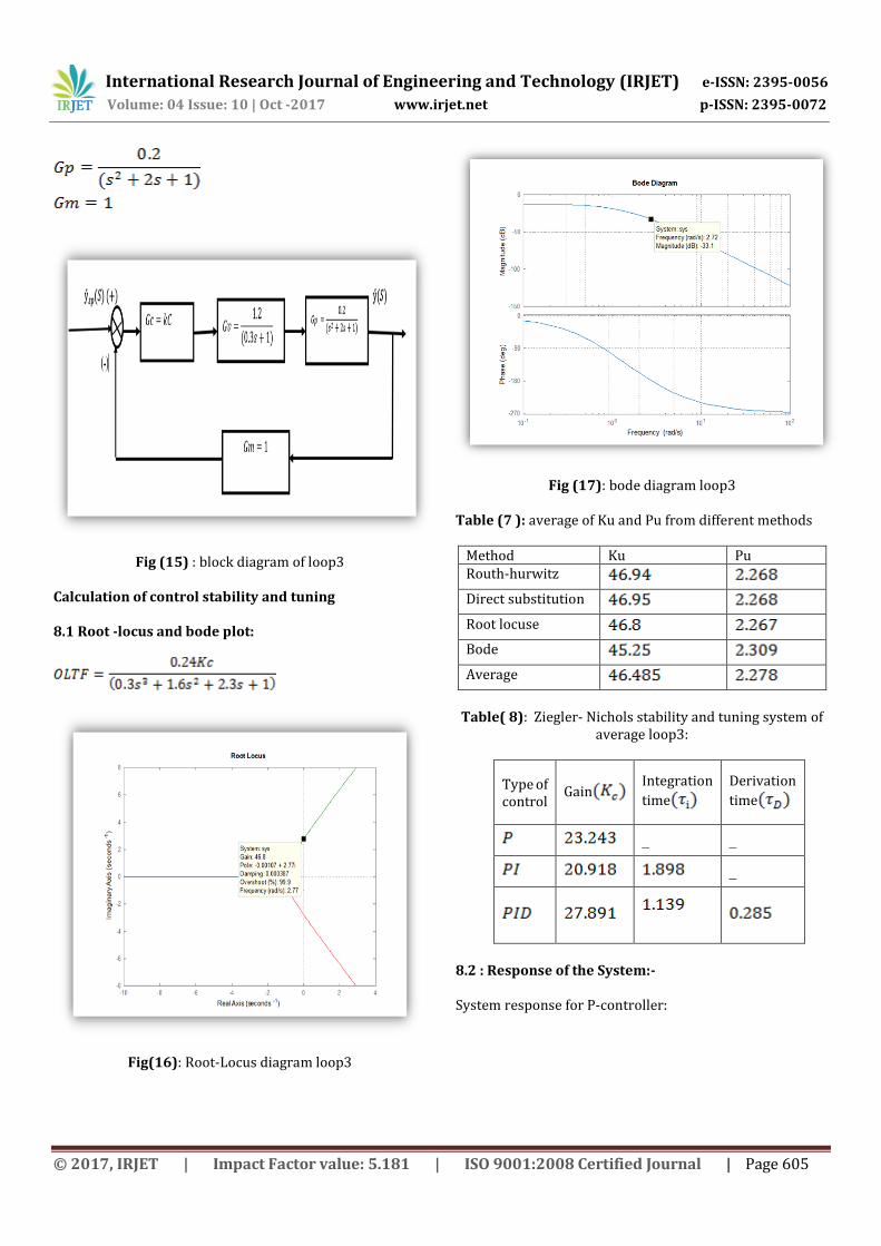
Fig (15) : block diagram of loop3 Calculation of control stability and tuning 8.1 Root -locus and bode plot:
Fig(16): Root-Locus diagram loop3
Fig (17): bode diagram loop3 Table (7 ): average of Ku and Pu from different methods
Method Ku Pu Routh-hurwitz
Direct substitution
Root locuse
Bode
Average
Table( 8): Ziegler- Nichols stability and tuning system of
average loop3:
Derivation
time
Integration
time Gain Type of
control
_ _
_
8.2 : Response of the System:- System response for P-controller:
International Research Journal of Engineering and Technology (IRJET) e-ISSN: 2395-0056
Volume: 04 Issue: 10 | Oct -2017 www.irjet.net p-ISSN: 2395-0072
© 2017, IRJET | Impact Factor value: 5.181 | ISO 9001:2008 Certified Journal | Page 606
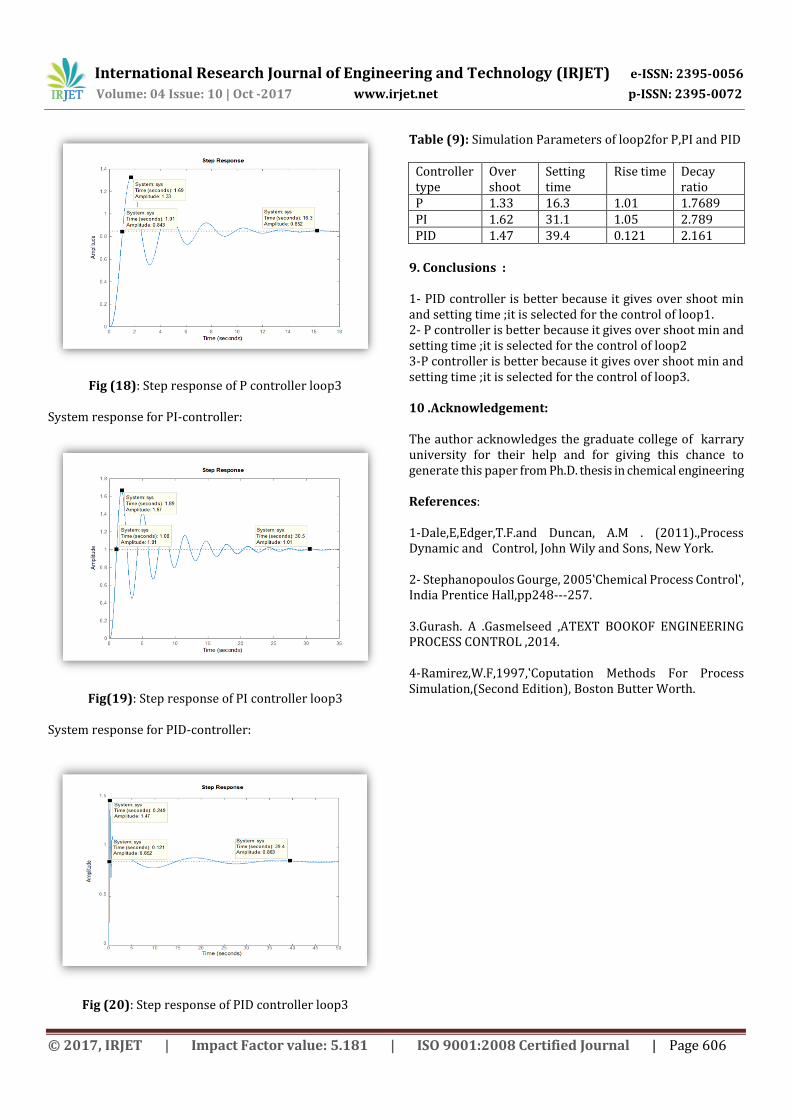
Fig (18): Step response of P controller loop3 System response for PI-controller:
Fig(19): Step response of PI controller loop3 System response for PID-controller:
Fig (20): Step response of PID controller loop3
Table (9): Simulation Parameters of loop2for P,PI and PID
Controller type
Over shoot
Setting time
Rise time Decay ratio
P 1.33 16.3 1.01 1.7689 PI 1.62 31.1 1.05 2.789 PID 1.47 39.4 0.121 2.161
9. Conclusions : 1- PID controller is better because it gives over shoot min and setting time ;it is selected for the control of loop1. 2- P controller is better because it gives over shoot min and setting time ;it is selected for the control of loop2 3-P controller is better because it gives over shoot min and setting time ;it is selected for the control of loop3. 10 .Acknowledgement: The author acknowledges the graduate college of karrary university for their help and for giving this chance to generate this paper from Ph.D. thesis in chemical engineering References: 1-Dale,E,Edger,T.F.and Duncan, A.M . (2011).,Process Dynamic and Control, John Wily and Sons, New York. 2- Stephanopoulos Gourge, 2005‛Chemical Process Control‛, India Prentice Hall,pp248---257. 3.Gurash. A .Gasmelseed ,ATEXT BOOKOF ENGINEERING PROCESS CONTROL ,2014. 4-Ramirez,W.F,1997,‛Coputation Methods For Process Simulation,(Second Edition), Boston Butter Worth.