Embed Size (px)
Citation preview

Control software for a linear robot arm
Giergiel, Mariusz
Published: 01/01/1986
Document VersionPublisher’s PDF, also known as Version of Record (includes final page, issue and volume numbers)
Please check the document version of this publication:
• A submitted manuscript is the author's version of the article upon submission and before peer-review. There can be important differencesbetween the submitted version and the official published version of record. People interested in the research are advised to contact theauthor for the final version of the publication, or visit the DOI to the publisher's website.• The final author version and the galley proof are versions of the publication after peer review.• The final published version features the final layout of the paper including the volume, issue and page numbers.
Link to publication
Citation for published version (APA):Giergiel, M. (1986). Control software for a linear robot arm. (TH Eindhoven. Afd. Werktuigbouwkunde, VakgroepProduktietechnologie : WPB; Vol. WPA0336). Eindhoven: Technische Universiteit Eindhoven.
General rightsCopyright and moral rights for the publications made accessible in the public portal are retained by the authors and/or other copyright ownersand it is a condition of accessing publications that users recognise and abide by the legal requirements associated with these rights.
• Users may download and print one copy of any publication from the public portal for the purpose of private study or research. • You may not further distribute the material or use it for any profit-making activity or commercial gain • You may freely distribute the URL identifying the publication in the public portal ?
Take down policyIf you believe that this document breaches copyright please contact us providing details, and we will remove access to the work immediatelyand investigate your claim.
Download date: 29. May. 2018

CONTROL SOFTWARE FOR A LINEAR
ROBOT ARM
By: Mariusz Giergiel
University of Mining and Metalurgy
Cracow, Poland
WPA-Report nr. 0336
ACKNOWLEDGEMENTS
I wish to express my acknowledgements to my coach,
Mr. P.C. Mulders, for his advice and kindness.
Greatest thanks also to H. Smit, who gave me part
of his time and helped in solving some hardware problems.
I also want to thank Rogier, Leon, Jean and many
others for a atmosphere of work, friendly and nice
wherever you go.
Eindhoven, October 1986
Mariusz J. Giergiel

Page 2
CONTENS
1 . SUMMARY 3
2. EINDHOVEN UNIVERSITY OF TECHNOLOGy 4
2.1 Mechanical Engineering Department 4
2.2 The FAIR Project 5
2.3 My Project 5
3. HARDWARE AND EQUIPMENT 6
3.1 Linear Robot Arm 6
3.2 Single Board Computer 8
3.3 Intellec Development System 11
3.4 Interfaces 12
4. SOFTWARE DESCRIPTION 14
4. 1 Main Segment 15
4.2 Teach Procedure 16
4.3 Replay Procedure 16
4.4 Driverobot Procedure 17
4.5 Procedures to communication witch console 17
4.6 ether Procedures 18
5. CONCLUSIONS 20
6. BIBLIOGRAPHY 21
7. APPENDIX A A1
8. APPENDIX B B1

Page 3
1. SU~Y
In this report control sfotware for driving linear robot arm is
described. Force sensor for teach operation is used. Method has been app
lied to a cu~tom linear robot arm, simple mechanical structure, to test
different control algorithms, but also in a goal of getting some expirience
in that view. Robot arm as a global system is controlled by an Intel 86/05
single board computer. Software was developed using Intel development system
and fully written in Pascal.
Page 4
2. EINDHOVEN UNIVERSITY OF TECHNOLOGY
"
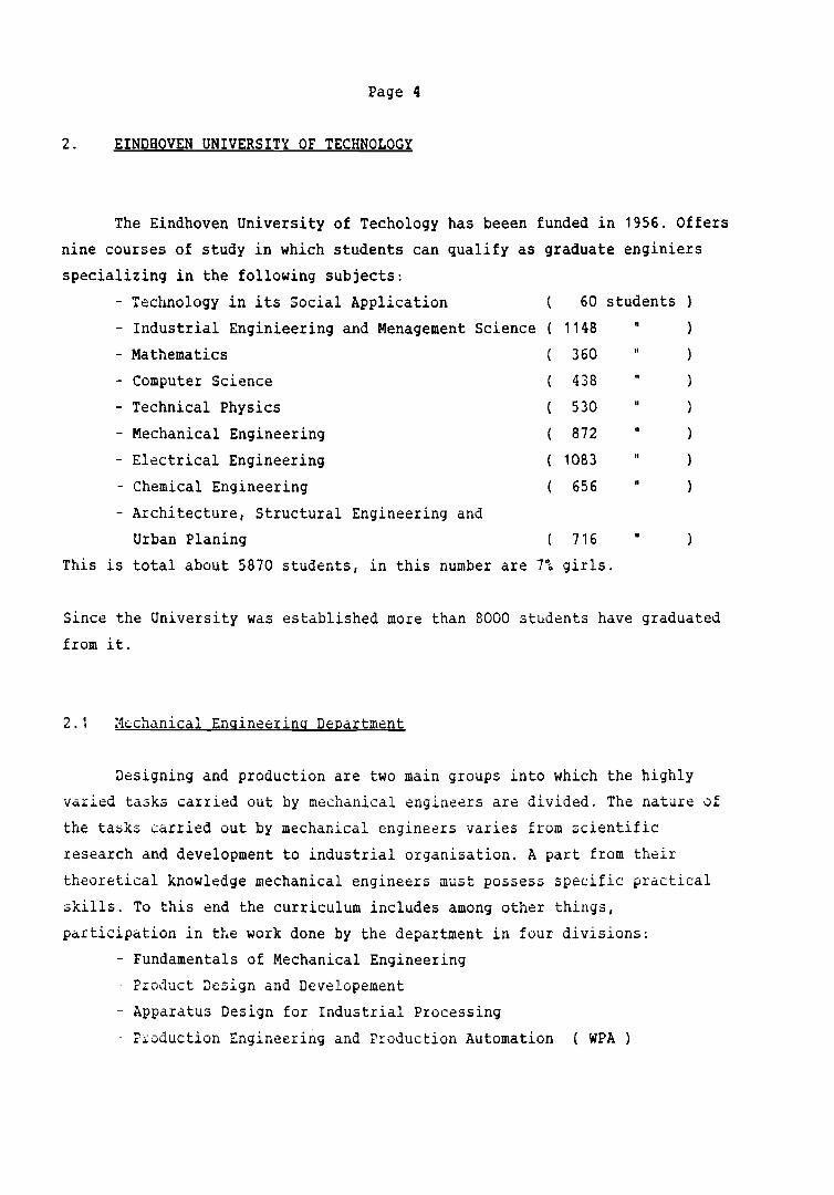
students60
1148
360
438
530
872
1083
656
Computer Science
Technical Physics
Mechanical Engineering
Electrical Engineering
Chemical Engineering
- Architecture, Structural Engineering and
Urban Planing 716
This is total about 5870 students, in this number are 7% girls.
The Eindhoven University of Techology has beeen funded in 1956. Offers
nine courses of study in which students can qualify as graduate enginiers
specializing in the following subjects:
- Technology in its Social Application
Industrial Enginieering and Menagement Science
Mathematics
Since the University was established more than 8000 students have graduated
from it.
2.1 ~echanical Engineering Department
Designing and production are two main groups into which the highly
varied tasks carried out by mechanical engineers are divided. The nature of
the ta~ks carried out by mechanical engineers varies from scientific
research and development to industrial organisation. A part from their
theoretical knowledge mechanical engineers must possess specific practical
skills. To this end the curriculum includes among other things,
participation in the work done by the department in four divisions;
- Fundamentals of Mechanical Engineering
- Product Design and Developement
- Apparatus Design for Industrial Processing
Production Engineering and Production Automation (WPA)

Page 5
there are about two hundred emplyed ( teachers and
and nine hundred students. I have worked for two months
In this department
technical personel
it the WPA division.
2.2 The FAIR Project Flexible Automation and Industrial Robots
The Research Project FAIR is directed and finansed by Dutch
Government. At the Eindhoven University of Technology the mechanical and
electrical engineering depatrments are involved in this project. They try to
find an approch to improve the flexibility with the aim of designing
components for flexible automation equipment. In addition of researches
students carry out their graduate work on detailed problems of the program.
The project is divided among several parts:
- general aspects of fixed and flexible automation
parts feeding and handling
- kinematics, dynamics, design aspects
- drive and control systems, applications of the systems
- arc-welding and the sensor systems
2.3 My project
Idea of my project was to develop control software for one axis linear
rvbot arm. This is continuation of projects by Eric Galet and by Loic
Janvier. Hardware was little modified according to previously used. Control
algoritm was developed by Leon Pijls. I tried to make flexible software
which might have possibilitiy to use different control algoritms. Some parts
of my software ego procedures to communicate witch console (terminal) from
single bard computer may by used also in other applications.

Page 6
3. HARDWARE AND EQUIPMENT
3.1 Linear Robot Arm.
since six axis robot can be considered as six times one axis robot
(excluding mathematical transformation), a linear one axis robot arm has
been designed at the University to test different pieces of equipment and
control schemes. The linear robot arm is constructed of two main parts: a
mechanical part and drive system. Schematic diagram of linear robot arm is
shown on figure 3.1.
'23
1 - robot arm
2 - support
3 - spindel
4 - DC servomotor
5 - force sensor
6 - Hall effect switches
7 - incremental transducter
Fig. 3.1
The mechanical part consist of mobile part with screw and motor and part
motionless (immobile). Drive unit is the DC servomotor which drives the

Page 7
carriage by means of a coupling spindle. In addition to drive system linerar
robot arm consist also of:
- force sensor mounted on the extermity of arm
- two Hall-effect switches mounted at each end of the arm
- incremental linear transducter used to measure position by position
counter
Specification of used linear robor arm is shown below:
maximum velocity mls
. I' 2maXlmum acce etatlon 5 mls
maximum load 50 kg
stroke 1000 mm
pusition accurancy +1- 0.1 mm
The main difference comparing my project to previus applicati0ns is ln robot
drive sy~tem. Motor is fully controlled by software and analog PID
controller used previously is disconnected. Differences are shown on figures
below. Figure 3.2 shows latest u~8d ~istcm witch analog PID controller.
Figure 3.3 shows system now in use.
ADC
lI'-~~--'\,I Pa.~~\ov,CO\A\AteV
\'-'l ~\tJ,ot,,"'es'-----------------------1
.11e.----~l~~ "01
11'-------------------------1 ~-~.e_c~1\.----------------------; ~dw;tev .
Fig 3.2

Page 8
o13> H-:, OAe ,-
~ [fo'" Se....,... 1tI ,
~ ...... ADC -..
~\.n0:0(JQ
...--- ~ ~~'iT"",~
~ -..IT -...I. ~:'hM ·r ~ l",-\ev"'"'f"~c •
~~"'(Q11
~ ~sC>x .. p~~~\Ov\ ~"" we"",e...rlll.\ ICO\A \AteV +Y\A\o\)cl~<:\ev'" , ..~~
Fig 3.3
3.2 Single Bord Computer
To control linear robot arm Intel iSBC 86/05 Single bord Computer is
used. Intel iSBC 86/05 is an Intel Multibu3 and iSBX Multimodule
compatibile, 16-bit computer system on a single printed circuit assembly.
Includes an 8 MHz 8086-2 microprocessor, 8K bytes of on-board static random
acces memory (RAM), 24 programmable parallel I/O lines, one serial port,
three programmable interval timers and programmable interrupt controller.
On-board sockets are provided for a maximum of 32K bytes of read only memory
(ROM). It is possible to upgrade ROM and RAM up to 1 Megabyte of total
system memory. Specifications of the iSBC 86/05 are provided in Table 3-1.
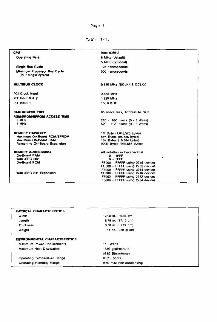
CPUOperating Rate
Single Bus Cycle
Minimum Processor Bus Cycle(four single cycles)
MUlTIBUS ClOCK
PCI Clock Input
PIT Input 0 & 2
PIT Input 1
RAM ACCESS TIMEROII/~OMIEPROM ACCESS TIME
8 MHz5 MHz
MEMORY CAPACITYMaximum On-Board ROM/EPROMMaximum On-Board RAMRemaining Off-Board Expansion
MEMORY ADDRESSINGOn-Board RAMWith iSBC 302On-Board ROM
With iSBC 341 Expansion
PHYSICAL CHARACTERISTICS
Width
Length
Thickness
Weight
ENVIRONMENTAL CHARACTERISTICSMaximum Power Requirements
Maximum Heat Dissipation
Operating Temperature Range
Operating Humidity Range
Page 9
Table 3-1.
Intel 8086-2
8 MHz (default)
5 MHz (optional)
125 nanoseconds
500 nanoseconds
9.830 MHz (BCLK/ & CCLKI)
2.458 MHz
1.229 MHz
153.6 KHz
85 nsecs max, Address to Data
285 - 660 nsecs (0 - 3 Waits)520 - 1120 nsecs (0 - 3 Waits)
1M Byte (1,048.576 bytes)64K Bytes (65,536 bytes)16K Bytes (16,384 bytes)920K Bytes (966.656 bytes)
All notation in hexadecimalo - 1FFFo - 3FFF
FEOOO - FFFFF using 2716 devicesFCOOO - FFFFF using 2732 devicesF8000 - FFFFF using 2764 devices
FCOOO - FFFFF using 2716 devicesF8000 - FFFFF using 2732 devicesFOOOO - FFFFF using 2764 devices
12.00 in. (30.48 em)
6.75 in. (17.15 em)
0.50 in. ( 1.27 em)
14 oz. (388 gram)
115 Watts
1640 geal/minute
(6.63 Btu/minute)
O°C - 55°C
90% max non-condensing

Page 10
Table 3-1. (continued)
ON BOARD I/O ADDRESSING
iSaC Connector J4 ( a-biI)
,sax Connector J4 (l6-biI)
,SBX Connector J3 ( a-bit)
iSBX Connector J3 (l6-bIt)
Interrupt Controller
Parallel Interface
Interval Timer
Serial Interface
INTERFACESMult/bus
Parallel I/O
Interrupt Requests
Interval Timer
,sax Bus
Senal I/O
80 - 9F Even Bytes Only
80 - SF
AD - BF Even Bytes Only
AD - AF
CO or C4 ICW1, OCW2, OCW3, Status, & Poll
C2 or C6 ICW2, ICW3, ICVJ4. & Masks
C8 PPI Port A
CA PPI Port B
CC PPI Port C
CE PPI Control
DO Counter 0
02 Counter 1
04 Counter 2
06 Counter Control
08 or DC Data
DA or DE Mode or Status
All signals TTL compatible
All signals TTL compatible
All signals TTL compatible
All signals TTL compatible
All signals TTL compatible
RS 232C compatible, data set
ELECTRICAL REQUIREMENTS
CONFIGURATION
Standard Board, no ROM/EPROM
Add for four 2716 devices
Add for four 2732 devices
Add for four 2764 devices
Add for iSBC 302 Option
Add for iSaC 341 Option
Add for each iSBX Multimodule
Add for iSBC 337 Option
STANDBY CURRENT REQUIREMENTS
Four 2716
Four 2732
Four 2764
iSSC 302 Option
,SSC 341 Option
BATTERY BACKUP REQUIREMENTS
MAXIMUM OPERATING REQUIREMENTS(with all options)
'·12Vdc and -12Vdc are required for RS232 applications only.
+5Vdc
4.9A
l00mA
150mA
180mA
108A
180A
300A
475mA
25mA
30mA
30mA
l60mA
laOmA
O.SA
122A
+12Vdc'
25mA
1.0A
1.025A
-12Vdc'23mA
1.0A
1.025A

Page 11
At this moment in the configuration is possible to use two timers, timer 0
and timer 1. Timer 2 is used as a baud rate generator for serial port to
communicate with console. In previous applications because of no connett ion
between timer 1 and interrupt controller was no possibility to use more then
timer O.
Unfortunetly system now in use has no 8087 floating point coprocessor. It is
compleatly impossible to implement real time control algoritms using
floating point aritmetics. Software emulation of 8087 takes much time, as
shown in Table 3-2.
Table 3-2.
"..,........t. becut..... ,"",-loo.1IS IIHa C1oc'1
Ift.lruct....
1017lOlI
Emulation
MUltiply IsllIQl. p,eclaloftl ,. 1,100
Multiply ldoutlI. preclalonl 27 2.'00
AcIcI 17 1,100
DIvid. laillQ'. prec:\8lOII1 31 3,200
Compere • , ,3011
loed 1.'''1I'' ~1.1oft1 • 1,7110
Slorw I.IIIQI. 1I"ec:l-'Onl "1.200
Squat. root 31 lUOO
T..".10 13,000
EapclMf'llelloft 100 17,100
In addition to iSBC 86/05 Memory Expansion Board 028A is used. It was
cvnn~ct8d JiLectly via Multibus interface. Contains 128K bytes of R&~.
3.3 Intellec Development System
In software developing Intellec Serie III Microcomputer Development
Sytstem was used. This systems gives possibilities for writing programs run
and debuging on development system or on the singlebords. It is possible to
cvnnect emulator for runing programs in their hardware environment.
Unfortunately possibilities of debuging programs on single board are very
Page 12
poor, preparing emulation and debuging on the development system takes many
time.
For program developing is possible to use high level languages:
- Pascal 86
- Fortran 86
- PL/M 86
They are extended, comparing to standard languages reports, supplying
possibilities of low level hardware menagement (input/output operations,
interrupt handling etc.).
Assemblay laguage is also avaliable as ASM 86.
User can divide program in several parts (modules) in different languages
and link them together with other library files. Program fully writen in one
language also may by divided in to modules. Unfortunately this way of
modulalization programs in Pascal give possibility to make them nearly
unreadable for other users and is in contradiction with basic Pascal ideas
defined by Niclaus Wirth, father of Pascal language. Time needed for
compilation, linking, relocation and preparing hexadecimal code is iritably
long. But stil this system is one of the best tols for single board software
developing.
3.4 Interfaces
System consist of few interfaces used in communication between single
board computer and robot arm. All of them were developed previously and used
without any changes.
- force sensor interface consist of force sesor, amplifier and analog
to digital ADC converter. ADC converter is connected to parallel
port.
- robot control system consist of digital to analog converter DAC and
power amplifier. DAC is connected to paralel port.
Hall switches sensors are connected using amplifier to interrupt
controller.
position counter is the 24-bit counter connected to single board
using iSBX interface.
Page 13
Position counter used now have few bugs. Becouse of them it is nesceseary to
make many converting operations during calculating actual position. It takes
time and decrese speed of software.
Page 15
4. SOFTWARE DESCRIPTION
Described software was fully writen in Pascal. Decision of using
Pascal becomes becouse:
- speed and volume of object code generated by Pascal 86 compiler is
enough for this application. Also interrupt procedures are fully
writen in Pascal. Because of hardware, speed possible to obtain
using assemblay is not needed.
Pascal lets to develope sfotware much more faster then assemblay
language and program is easy to understand. Correction of errors and
any modifications are easy to do when Pascal is used. Large
assembly programs are very difficult to understand and modify by
other users.
Program consist of few sets of procedures. In Appendix A are shown
listings of all segments independently compiled. They are fully commented
and selfdocumented. More information about them is puted in nLxt paragraphs.
Many of them may be used in different programs developed for singleboards,
ego module terminal, which consist of set useful procedures for
co~~unication between singleboard and console (terminal) screen. Interrupt
procedurc~ also may be u~ed in developing programs for solving different
tasks. Because they are also written in Pascal they are easy to understand
and easy to modify. Presented software may work on different types of single
beard computers. In this case may be possible to:
change adresses of control refisters of PPI (Programmeble Paralel
Interface), or change all procedure for PPI initialization in
case of different type of PPI.
- change adresses of control registers of PIT (Programeble Interwal
Timer), or change all procedure for PIT initialization and PIT
setting in case of different type of PIT.
- change addreses of control registers of PIC (Programeble Interrupt
Cantraler), or change all procedures for PIC initialization in case
of different type of PIT.
- it may by necessary to change numbers assigned to interrupts inside
INTERRUPTSET procedure.
Page 16
deepending on type of microprocessor used in a singleboard it may be
neceseary to change compiler option MOD86/MOD186. MOD86 specifies,
that object module includes instructions for execution on the
8086 processor. MOD186 control allows compiler to generate extended
code for use on the 80186 processor.
- in case of interface modifications it may be necessary to change
addresses or all handling procedures.
To make this modifications in neceseary to refear Reference Manual for
type of single board used.
Presented program was developed using Intellec Series III Microcomputer
Developing System and tested on iSBC 86/05. Used singleboard consist of:
8255 PPI, 8359 PIT and 8259 PIC.
Appendix B contains full Pascal listing of developed program wihout use of
dividing program to separatly compiled modules possibilities offered Pascal
86 compiler. Because of normal Pascal structure of it this program it is
easier to understand and analyse comparing to listings presented in Appendix
A.
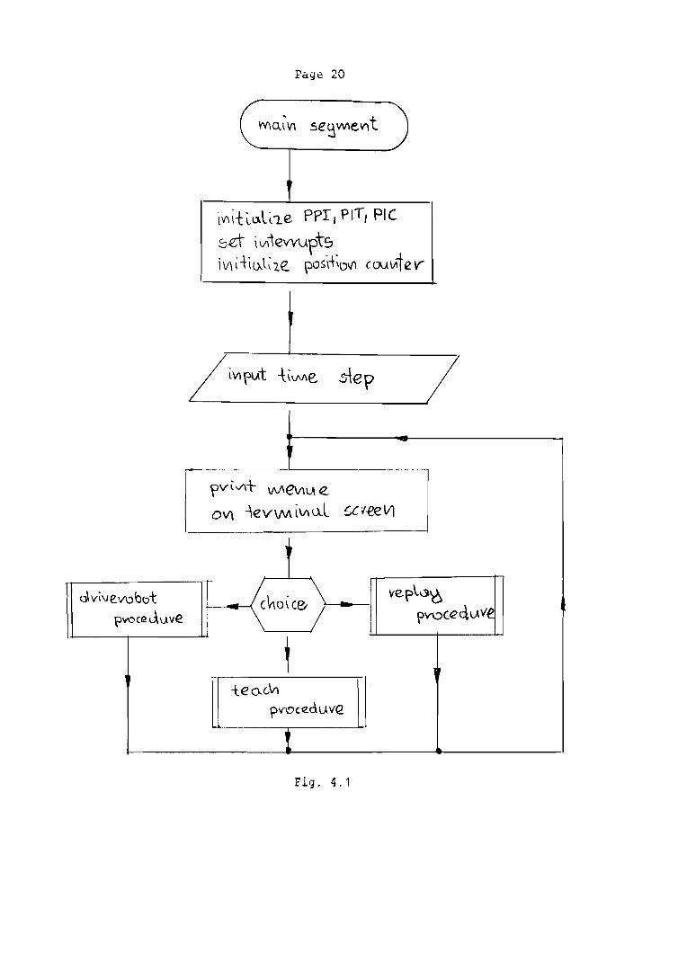
4.1 Main segment
Main segment is very simple. It (using procedures PPIINIT, PICINIT,
PITINIT) initialize hardware, it means PPI, PIT, PIC, sets interrupts (using
procedure INTERRUPTSET), initialize position counter (using procedure
?C::7ICNCOUNTERI:jIT), and ask user about time step required. Then starts
il~finite loop inside wchich print: mcnu~ to make chaise beetwen driving
robot to required position, teching robot via force sensor, or replaying
teached trajectory, waits for user choice and after puts control to
required procedure. After procedure stops control is putted back into
infinite loop in main program. Procedures called from described loop are
named: DRIVEROBOT, TEAH and REPLAY. Schematic diagram of main segment is
shuwn on figure 4.1.
Page 17
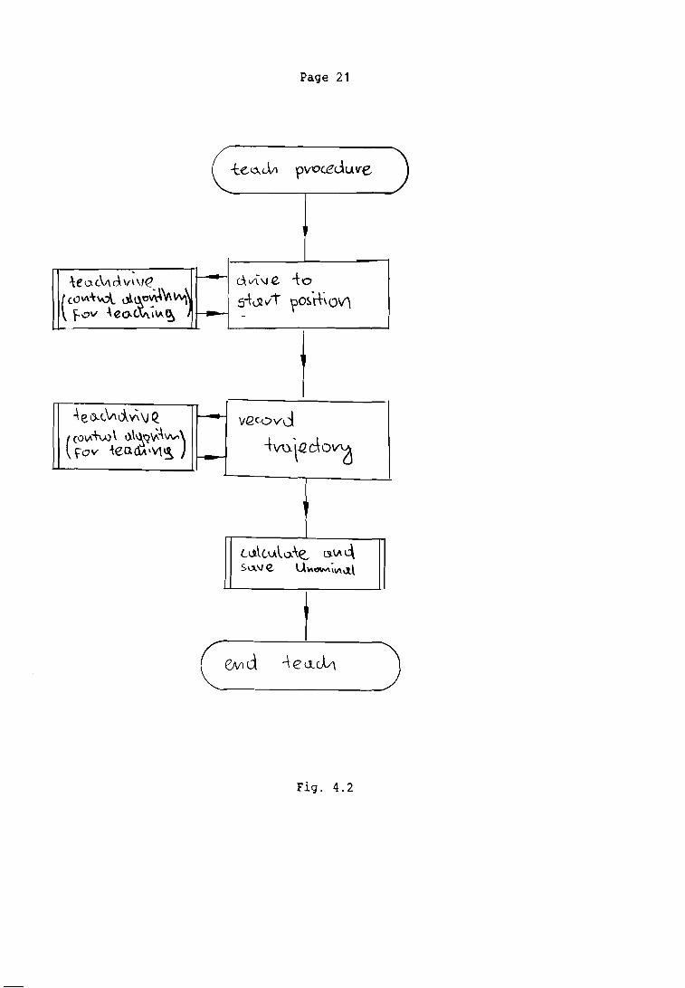
4.2 Teach procedure
This procedure is used to teaching robot using force sensor. In this
project it is not essential to implement teaching via force sensor, but it
was done becouse of very easy teach operation and also simple algorithm for
this method of teaching. As a data structure TACH and PEPLAY procedures use
the same buffer area. It is decribed as:
type Trajectory = record
NoPoints integer;
Stime word;
PosV array [ 1.. MaxMove ] of longint;
Ctrl array [ 1.. MaxMove ] of char;
end;
It contains PosV position and velocity. Becouse longint~get u~upies 32 bits
and positioincounter is 24 bits in last eight bits velocity is puted. To
implement optimal control algorithm also information about Unominal is
needed. It occupies eight bits and is stored into Ctrl.
At the beginning of teach opearation offset point for force sensor is
calculated and lately u~ed. It was don~ te~ouse of pr(lblems with setting
right offset point in analog amplifier in force transducter. TEACH procedure
allows you first to drive to start position, and then to record trajectory.
How long is time for trajectory recording depeends of time step required
(Stime) and number of puints possible to store (MaxMove). This depeends on
memory instaled on memory expansion board.
Schematic diagram of TEACH procedure is shown on Figure 4.2. TEACH procedure
uS~S TEAC~~RIVE internal procedure to calculate control signal for robot.
After teach operation internal procedure UNCALe is called. This procedure
should calculate and store Unominal. If such information is not needed
UnCalc and part of data structure to store may be removed.
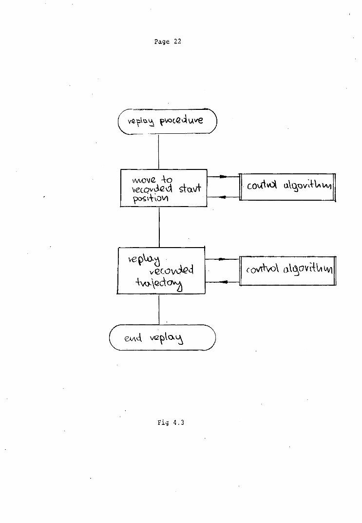
4.3 Replay procedure
This procedure is ~imilar to previously described Teach procedure.
Using information stored in buffer first, drives robot to start position and
then replays teached trajectory. Schematic diagram of REPLAY procedure is

Page 18
shown on Figure 4.3. This procedure uses GOPOSITION procedure to move robot
to required position with required velocity. GOPOSITION using control
algorithm should calculate control signal and send it to the robot, then put
control back to REPLAY procedure.
4.4 DriveRobot procedure
This procedure may be used to drive robot to required position. It
should calculate control signal for robot to go to position. In this case
velocity is not important. Schmatic diagram of this procedure is shown of
Figure 4.4
4.5 Procedures for communication with console (terminal)
To communicate between single board computer and console (terminal)
connected into serial port a set of procedures was developed. They are
flexible and easy to use also in other applications. This set of procedures
consist of:
PRJNTTR procedure which allows to print ASCII string on console
screen. Type String is defined as array [ 1.. MaxString ] of char. MaxString
is constant which defines maximum lenght of string. Unfortunately Pascal did
not gives any possibility to send text of different length. Becouse of that
PrintTR ignores all spaces from the right of the text. It allows to print on
screen text shorter then MaxString.
READCOMMANDTR procedure give possibility to read commanJ from terminal
and check if this command exist among possible commands. If command exist it
is accepthed, otherwise is ignored and procedure waits for valid command.
LINETR procedure ejects required number (put empty) lines on terminal
screen.
TABTR procedure makes required nuber of spaces on terminal screen.
TERMINALINIT procedure clears terminal screen.
READINTEGERTR function allows to read integer number from terminal.
Accepts spaces and/or ,_, mark at the beginning. Procedure does not accept
numbers greater than Maxint. If user try to put greater number the last

Page 19
rihgt value will be assigned. It is possible to define maximum lenght of
string represenatation of number on console screen.
INTEGERTOSTRING procedure allows to convert integer number into text
string to be printed using PRINTTR procedure. As an input parameter it is
necessary to send required lenght of string. If lenght od string is not
enough to put representation of number sended it would be field by '*'
characters. After conversion text is left justified.
4.6 Other procedures
Presented software includes many other procedures for hardware
initialization, interrupts handling, communication between single board
computer and interfaces, ego to reading force from force sensor, reading
position from position counter etc. They are simle and good commented in
source li~tings. Because of this is not necessary to describe them here.
-r-r-------.--t-
(J\ vl\levobt>tf;-lvOCI2 dljve
Pagt 20
\V\\1:Lo.llLe PPI, PIT, PIC
sci \V\levvuptsjV\ i -\- \{).l~ le PO$i-t~DI{l cau",ie V-
[-~~lv'\+ vv'e\l\lA e ~ov\ -\ev\Mi\l\~L £,Cv-eelll I
__________1
t
~: teo..G\r!
PV\9Cllc\.U VQ.___.-- LL
Page 21
d. vI:'! Q. -t 0
S-tVlvT ?os.rhoV\
j4el)..(,"'d~\) Q f-- vec.ovd(N~-+W\ 1).\~"?~~'vV»
-tvo.tQdo~fOv 1ea.aJ\'\1.~ l--
Ll1\tv.~0..\e l.).\A c\SU\Je.. U"''''''''~V\-1\
Fig. 4.2
Page 22
\N'vOva. -\0 vetO"Je d £to.v\- . CO\A.-tvd. ().\\6'Ov~HI\ \Iv)
~~+~OV1 ,------u.------J
ve~\.o..() . ve(OvJ.e~
4:'A).\Qd~
Fig 4.3

Page 23
Fig. 4.4

Page 24
S. CONCLUSION
Using optimum control algorithms for robot driving is a very
interesting idea. It gives posibilities to eliminate analog controlers from
system.
Iteresting way it is also to use long time step, or better algoritms for
flexible changing time step during teach operation according to required
robot velocity at the moment. Connecting witch linear regresion algoritm or
spline function method gives possibility to make recording time longer
without loosing accuracy using the same memory area for storing information
about trajectory. But such methods make necesseary to use fast cv~trol
computers to make reque~ted operations in real time.
Teaching using force sensors makes t8achiHg operation ~asy dnd requires
programming experience from operator. This methoJ givs also p8rf~ct ~ontdct
with the robot and the environment during teaching operation.
Less than two months spended at Technical University of Eindhoven it
is a very short time. It is just enough to have general vi2w for problems
solved in rubotics labolatory. But I hope, that effects of my work will by
useful for other persons.

Page 25
6. BIBLIOGRAPHY
G. Hirzinger, J. Heindl: Sensor Programming
Robots and Forces/Troques simultaneously.
Sensory Cuntrols
- a New Way for Teaching a
Nov.1983, Robot Visions and
G. Hirzinger: Direct Digital Robot Control Using a Force/Troque Sensor. IFAC
Real Time Digital Control Applications
L.V.M. van Bummel, P.W. Koumans, A.C.R van der Wolf: On the Design of a
Linear Acutator for a Modular Robot System. Annals of the CIRP
Vul.34/1/1985
E. G~lct: Teach Operation With a Force Sensor for a Linear Robot Arm. WPB
Report no. 0255
L. Janvier: Teaching Operations Witch a Force Sensor for a Linear Robot Arm.
WPA-Report no. 0306


![Human Arm Imitation · Human-robot skeleton mapping Robot Joint Angles D-H Parameters [2] Human Arm Robot Arm References [2] [4] Industrial Robots can now be trained and controlled](https://img.pdfslide.us/doc/110x75/5f76b9ded7aa2d6f12317b91/human-arm-imitation-human-robot-skeleton-mapping-robot-joint-angles-d-h-parameters.jpg)