Embed Size (px)
Citation preview

Electric Drivesand Controls
Hydraulics
Linear Motion andAssembly Technologies
Pneumatics
Service
Rexroth IndraDriveDrive ControllersControl Sections
R911295012Edition 06
Project Planning Manual

Rexroth IndraDriveDrive ControllersControl Sections
Project Planning Manual
DOK-INDRV*-CSH********-PR06-EN-P
RS-f3b929d50a6846ac00606b3786952866-2-en-US-5
Edition Release Date Notes
120-2400-B301-06/EN 2007/03 see chapter "Changes"
Copyright ® Bosch Rexroth AG 2007Copying this document, giving it to others and the use or communication of thecontents thereof without express authority, are forbidden. Offenders are liablefor the payment of damages. All rights are reserved in the event of the grant ofa patent or the registration of a utility model or design. (DIN 34-1)
Validity The specified data only serve to describe the product. No statements concern‐ing a certain condition or suitability for a certain application can be derived fromour information. The given information does not release the user from the ob‐ligation of own judgement and verification. It must be remembered that ourproducts are subject to a natural process of wear and aging.
Published by Bosch Rexroth AG, Bgm.-Dr.-Nebel-Str. 2, D-97816 Lohr a. Main Telephone+49 (0)93 52 / 40-0, Tx 68 94 21, Fax +49 (0)93 52 / 40-48 85http://www.boschrexroth.deDept. EDY1 (RR/US/BB)
Note This document has been printed on chlorine-free bleached paper.
Title
Type of Documentation
Document Typecode
Internal File Reference
Record of Revision
Bosch Rexroth AG | Electric Drivesand Controls
Rexroth IndraDrive | Project Planning Manual

Table of ContentsPage
1 Introduction.................................................................................................................... 11.1 Guide to the Documentation................................................................................................................... 11.1.1 Documentation Structure .................................................................................................................... 11.1.2 Changes.............................................................................................................................................. 11.1.3 Reference Documentations ................................................................................................................ 2
Overview........................................................................................................................................... 21.1.4 Box with Project Planning Manuals on Rexroth IndraDrive ................................................................ 31.1.5 Your Feedback.................................................................................................................................... 31.2 Basic Design of the Rexroth IndraDrive Controllers .............................................................................. 41.2.1 General Information............................................................................................................................. 41.2.2 Delivery ............................................................................................................................................... 41.2.3 Mounting and Dismounting the Control Section ................................................................................. 5
General Information.......................................................................................................................... 5Training............................................................................................................................................. 5ESD Protection................................................................................................................................. 5Limited Number of Plug-In Actions................................................................................................... 5
2 Important Directions for Use ......................................................................................... 72.1 Appropriate Use ..................................................................................................................................... 72.1.1 Introduction.......................................................................................................................................... 72.1.2 Areas of Use and Application.............................................................................................................. 72.2 Inappropriate Use .................................................................................................................................. 8
3 Safety Instructions for Electric Drives and Controls ...................................................... 93.1 Safety Instructions - General Information............................................................................................... 93.1.1 Using the Safety Instructions and Passing them on to Others............................................................ 93.1.2 How to Employ the Safety Instructions................................................................................................ 93.1.3 Explanation of Warning Symbols and Degrees of Hazard Seriousness............................................ 103.1.4 Hazards by Improper Use.................................................................................................................. 113.2 Instructions with Regard to Specific Dangers....................................................................................... 123.2.1 Protection Against Contact with Electrical Parts and Housings......................................................... 123.2.2 Protection Against Electric Shock by Protective Extra-Low Voltage................................................. 133.2.3 Protection Against Dangerous Movements....................................................................................... 133.2.4 Protection Against Magnetic and Electromagnetic Fields During Operation and Mounting.............. 163.2.5 Protection Against Contact with Hot Parts......................................................................................... 163.2.6 Protection During Handling and Mounting......................................................................................... 163.2.7 Battery Safety.................................................................................................................................... 173.2.8 Protection Against Pressurized Systems........................................................................................... 17
4 Identifying the Control Section .................................................................................... 194.1 Type Plates .......................................................................................................................................... 194.1.1 General Information........................................................................................................................... 194.1.2 Type Plates at the Drive Controller.................................................................................................... 19
Project Planning Manual | Rexroth IndraDrive Electric Drivesand Controls
| Bosch Rexroth AG I/V
Table of Contents

Page
4.1.3 Type Plates at the Control Section.................................................................................................... 20Control Section Type Plate ............................................................................................................ 20Firmware Type Plate ..................................................................................................................... 20
5 Rexroth IndraDrive Control Sections........................................................................... 215.1 Overview of Types ............................................................................................................................... 215.2 Overview of Functions and Interfaces ................................................................................................. 215.3 BASIC Control Sections ....................................................................................................................... 235.3.1 Type Codes BASIC and BASIC UNIVERSAL................................................................................... 23
Type Code BASIC CSB01.1N ....................................................................................................... 23Type Code BASIC UNIVERSAL Single-Axis CSB01.1C................................................................ 24Type Code BASIC UNIVERSAL Double-Axis CDB01.1C ............................................................. 25
5.3.2 Dimensions BASIC............................................................................................................................ 27Dimensions BASIC and BASIC UNIVERSAL Single-Axis ............................................................. 27Dimensions BASIC UNIVERSAL Double-Axis .............................................................................. 28
5.3.3 CSB01.1N-FC - BASIC OPENLOOP ............................................................................................... 29Front View with Connections at Basic Circuit Board...................................................................... 29Functions........................................................................................................................................ 29
5.3.4 CSB01.1N-SE - BASIC SERCOS .................................................................................................... 33Front View with Connections.......................................................................................................... 33Functions........................................................................................................................................ 33
5.3.5 CSB01.1N-PB - BASIC PROFIBUS ................................................................................................. 38Front View with Connections.......................................................................................................... 38Functions........................................................................................................................................ 38
5.3.6 CSB01.1N-AN - BASIC ANALOG .................................................................................................... 43Front View with Connections.......................................................................................................... 43Functions........................................................................................................................................ 43
5.3.7 CSB01.1C - BASIC UNIVERSAL Single-Axis .................................................................................. 48Front View with Connections.......................................................................................................... 48Functions........................................................................................................................................ 48Optional Slots ................................................................................................................................ 53
5.3.8 CDB01.1C - BASIC UNIVERSAL Double-Axis ................................................................................. 55Front View with Connections.......................................................................................................... 55Functions........................................................................................................................................ 56Optional Slots ................................................................................................................................ 62
5.4 ADVANCED ......................................................................................................................................... 645.4.1 Type Code ADVANCED (CSH01.1C) .............................................................................................. 645.4.2 Type Code ADVANCED (CSH01.2C) .............................................................................................. 665.4.3 Dimensions ADVANCED .................................................................................................................. 685.4.4 CSH01.1C - ADVANCED ................................................................................................................. 69
Front View with Connections.......................................................................................................... 69Functions........................................................................................................................................ 69Optional Slots CSH01.1C .............................................................................................................. 75
5.4.5 CSH01.2C - ADVANCED ................................................................................................................. 76General Information........................................................................................................................ 76Front View with Connections ......................................................................................................... 77
II/V Bosch Rexroth AG | Electric Drivesand Controls
Rexroth IndraDrive | Project Planning Manual
Table of Contents

Page
Functions........................................................................................................................................ 77Optional Slots CSH01.2C .............................................................................................................. 84
6 Optional Modules for Control Sections ....................................................................... 876.1 Overview .............................................................................................................................................. 876.2 Master Communication ........................................................................................................................ 886.2.1 SE - SERCOS .................................................................................................................................. 886.2.2 PB - PROFIBUS ............................................................................................................................... 896.2.3 PL - Parallel Interface ....................................................................................................................... 93
X15, Parallel Interface - PL............................................................................................................. 936.2.4 CO - DeviceNet / CANopen .............................................................................................................. 96
X60, DeviceNet / CANopen Interface - CO.................................................................................... 96Display Elements............................................................................................................................ 97
6.2.5 CD - DeviceNet / CANopen (Preliminary) ......................................................................................... 99X61, DeviceNet / CANopen Interface - CD..................................................................................... 99Display Elements.......................................................................................................................... 100
6.2.6 S3 - SERCOS III ............................................................................................................................. 1016.2.7 CCD - Cross Communication ......................................................................................................... 1036.3 Encoder Evaluation............................................................................................................................. 1046.3.1 ENS - Standard Encoder Evaluation .............................................................................................. 104
Interface Standard Encoder Evaluation ENS............................................................................... 104Properties of ENS......................................................................................................................... 105Signal Assignment to the Actual Position Value........................................................................... 106Connection Diagrams ENS........................................................................................................... 107Connection Diagrams ENS with Third-Party Encoder.................................................................. 107Allowed Encoder Cable Lengths at ENS ..................................................................................... 109
6.3.2 EN1 - Resolver and HSF Encoder Evaluation ................................................................................ 109Interface Resolver and HSF Encoder Evaluation EN1................................................................. 109Properties EN1............................................................................................................................. 110Signal Assignment to the Actual Position Value........................................................................... 112Connection Diagrams EN1........................................................................................................... 112
6.3.3 EN2 - Encoder Evaluation .............................................................................................................. 113Interface Encoder Evaluation EN2............................................................................................... 113Properties EN2............................................................................................................................. 114Signal Assignment to the Actual Position Value........................................................................... 116Connection Diagrams EN2........................................................................................................... 117Allowed Encoder Cable Lengths at EN2 ..................................................................................... 118
6.3.4 MEM - Encoder Emulation .............................................................................................................. 120Interface Encoder Emulation MEM............................................................................................... 120Incremental Encoder Emulation................................................................................................... 121Absolute Encoder Emulation (SSI Format)................................................................................... 123
6.4 I/O Extensions.................................................................................................................................... 1256.4.1 MA1 - Analog I/O Extension ........................................................................................................... 1256.4.2 MD1 - Digital I/O Extension ............................................................................................................ 1286.4.3 MD2 - Digital I/O Extension and SSI Encoder Evaluation .............................................................. 129
Interface........................................................................................................................................ 129
Project Planning Manual | Rexroth IndraDrive Electric Drivesand Controls
| Bosch Rexroth AG III/V
Table of Contents

Page
X17, Digital I/O Extension on MD2............................................................................................... 130X16, SSI Encoder Evaluation on MD2.......................................................................................... 132
6.5 Safety Technology.............................................................................................................................. 1346.5.1 L1 - Starting Lockout ...................................................................................................................... 134
Description.................................................................................................................................... 134X41, Connection Point Starting Lockout L1.................................................................................. 134Connection Accessory, Starting Lockout L1................................................................................. 135
6.5.2 S1 - Safety Technology .................................................................................................................. 135Description Safety Technology S1............................................................................................... 135X41, Connection Point Safety Technology S1.............................................................................. 135
6.6 Control Panels.................................................................................................................................... 1366.6.1 Standard Control Panel“S” ............................................................................................................. 1366.6.2 Comfort Control Panel“C” ............................................................................................................... 1376.7 Memory............................................................................................................................................... 1386.7.1 X7, Memory Card PFM02.1 ............................................................................................................ 138
7 Technical Data Functions.......................................................................................... 1397.1 Relay Contacts .................................................................................................................................. 1397.1.1 Symbolic Illustration......................................................................................................................... 1397.1.2 Relay Contact Type 1 ..................................................................................................................... 1397.1.3 Relay Contact Type 2 ..................................................................................................................... 1397.1.4 Relay Contact Type 3 ..................................................................................................................... 1407.2 Digital Inputs/Outputs......................................................................................................................... 1407.2.1 General Information......................................................................................................................... 1407.2.2 Digital Inputs ................................................................................................................................... 140
Digital Inputs Type 1 (Standard) .................................................................................................. 140Digital Inputs - Probe.................................................................................................................... 141
7.2.3 Digital Outputs ................................................................................................................................ 1437.3 Analog Inputs/Outputs........................................................................................................................ 1447.3.1 General Information......................................................................................................................... 1447.3.2 Connection Diagram - Example ...................................................................................................... 1447.3.3 Analog Inputs .................................................................................................................................. 145
Analog Input Type 1 .................................................................................................................... 145Analog Input Type 2 .................................................................................................................... 146Analog Input Type 3 .................................................................................................................... 146Analog Input Type 4 .................................................................................................................... 147
7.3.4 Analog Outputs ............................................................................................................................... 148Analog Output Type 1 .................................................................................................................. 148Analog Output Type 2 .................................................................................................................. 148Analog Output Type 3 .................................................................................................................. 149
7.4 X2, Serial Interface (RS232) .............................................................................................................. 1497.4.1 General Information......................................................................................................................... 1497.4.2 Connection Diagrams Serial Interface to PC .................................................................................. 1507.5 X26, Engineering Interface ................................................................................................................ 151
IV/V Bosch Rexroth AG | Electric Drivesand Controls
Rexroth IndraDrive | Project Planning Manual
Table of Contents
Page
8 Other Technical Data................................................................................................. 1538.1 Power Consumption .......................................................................................................................... 1538.1.1 General Information......................................................................................................................... 1538.1.2 Basic Circuit Boards of Control Section .......................................................................................... 1538.1.3 Optional Modules ............................................................................................................................ 1548.2 Connections........................................................................................................................................ 1548.2.1 General Information......................................................................................................................... 1548.2.2 Connections with Spring Terminals ................................................................................................ 1548.2.3 Connections with Screw Terminal Blocks ....................................................................................... 155
9 Accessories ............................................................................................................... 157
10 Disposal and Environmental Protection..................................................................... 15910.1 Disposal.............................................................................................................................................. 15910.1.1 Products.......................................................................................................................................... 15910.1.2 Packaging Materials........................................................................................................................ 15910.2 Environmental Protection.................................................................................................................... 15910.2.1 No Release of Hazardous Substances............................................................................................ 15910.2.2 Materials Contained in the Products................................................................................................ 159
Electronic Devices........................................................................................................................ 159Motors........................................................................................................................................... 159
10.2.3 Recycling......................................................................................................................................... 160
11 Service & Support...................................................................................................... 16111.1 Helpdesk............................................................................................................................................. 16111.2 Service Hotline.................................................................................................................................... 16111.3 Internet................................................................................................................................................ 16111.4 Helpful Information.............................................................................................................................. 161
Index.......................................................................................................................... 163
Project Planning Manual | Rexroth IndraDrive Electric Drivesand Controls
| Bosch Rexroth AG V/V
Table of Contents

Bosch Rexroth AG | Electric Drivesand Controls
Rexroth IndraDrive | Project Planning Manual

1 Introduction1.1 Guide to the Documentation1.1.1 Documentation StructureChapter Contents
1 Introduction general information
2 Important Directions for Usesafety
3 Safety Instructions for Electric Drives and Controls
4 Identifying the Control Section
product description (for those doing project planning)
5 Rexroth IndraDrive Control Sections
6 Optional Modules for Control Sections
7 Technical Data Functions
8 Other Technical Data
9 Accessories
10 Disposal and Environmental Protection practical application (for operators and maintenance staff)
Fig.1-1: Documentation structure
1.1.2 ChangesChanges in Comparison to Previ‐
ous Edition Chap‐ter
Changes
5 additional requirement of polarity reversal protection diodes at I/O extensionmodules includedsignal names harmonized
6.3 min. amplitude encoder signal for ENS, EN1 and EN2 specified
6 connection diagram EN2 with C0 modified - shield at GNDconnection “EN1 with Hall sensor box SHL01” includedidentifier for connection points addedcurrent consumption L1 and S1 specified with minimum and maximum values
8 power consumption of optional modules arrangedpower consumption of non-configurable control sections with entire equip‐ment included
7.2.2 technical data of probe inputs addedadditional probe type (20 μs–200 μs) included
7.3.3 technical data (among other things, input bandwidth, input resistance, con‐verter width) corrected
7.3.2 example of connection diagram for shield connection at X32 added
Fig.1-2: Changes
Project Planning Manual | Rexroth IndraDrive Electric Drivesand Controls
| Bosch Rexroth AG 1/166
Introduction

1.1.3 Reference DocumentationsOverview
The following documentations contain detailed information on theallowed applications, as well as the application, ambient and oper‐ating conditions.
Reference Documentations - Drive Controllers
Title Kind of documentation Document typecode1)
Rexroth IndraDrive – Drive System Project Planning Manual DOK-INDRV*-SYSTEM*****-PRxx-EN-P
Rexroth IndraDrive Supply Units and Pow‐er Sections
Project Planning Manual DOK-INDRV*-HMV-S-D+HCS-PR01-EN-P
Rexroth IndraDrive – Drive ControllersControl Sections
Project Planning Manual DOK-INDRV*-CSH********-PRxx-EN-P
Rexroth IndraDrive Additional Compo‐nents
Project Planning Manual DOK-INDRV*-ADDCOMP****-PRxx-EN-P
1) In the document typecodes, "xx" is a wild card for the current edition ofthe documentation (example: "PR01" is the first edition of a ProjectPlanning Manual)
Fig.1-3: Documentations - overview
The following documentations describe the firmware and containinformation on its scope of functions.
Reference Documentations - Firmware for Drive Controllers
Title Kind of documentation Document typecode1)
Rexroth IndraDrive Firmware for DriveControllers
Functional Description DOK-INDRV*-MP*-02VRS**-FKxx-EN-P
Rexroth IndraDrive Firmware for DriveControllers
Functional Description DOK-INDRV*-MP*-03VRS**-FKxx-EN-P
Rexroth IndraDrive Firmware for DriveControllers
Functional Description DOK-INDRV*-MP*-04VRS**-FKxx-EN-P
Rexroth IndraDrive Firmware for DriveControllers
Parameter Description DOK-INDRV*-GEN-**VRS**-PAxx-EN-P
Rexroth IndraDrive Firmware for DriveControllers
Troubleshooting Guide DOK-INDRV*-GEN-**VRS**-WAxx-EN-P
Rexroth IndraDrive Integrated SafetyTechnology
Functional and ApplicationDescription
DOK-INDRV*-SI*-**VRS**-FKxx-EN-P
1) In the document typecodes, "xx" is a wild card for the current edition ofthe documentation (example: "PR01" is the first edition of a ProjectPlanning Manual)
Fig.1-4: Documentations - overviewReference Documentations - Motors
Title Kind of documentation Document typecode1)
Rexroth Connection Cables Selection Data DOK-CONNEC-CABLE*STAND-AUxx-EN-P
Rexroth IndraDyn A Asynchronous Motors Project Planning Manual DOK-MOTOR*-MAD/MAF****-PRxx-EN-P
2/166 Bosch Rexroth AG | Electric Drivesand Controls
Rexroth IndraDrive | Project Planning Manual
Introduction

Title Kind of documentation Document typecode1)
Rexroth IndraDyn H Frameless Synchro‐nous Spindle Motors
Project Planning Manual DOK-MOTOR*-MBS-H******-PRxx-EN-P
Rexroth IndraDyn L Synchronous LinearMotors
Project Planning Manual DOK-MOTOR*-MLF********-PRxx-EN-P
Rexroth IndraDyn S Synchronous Motors Project Planning Manual DOK-MOTOR*-MSK********-PRxx-EN-P
Rexroth IndraDyn T Synchronous TorqueMotors
Project Planning Manual DOK-MOTOR*-MBT********-PRxx-EN-P
1) In the document typecodes, "xx" is a wild card for the current edition ofthe documentation (example: "PR01" is the first edition of a ProjectPlanning Manual)
Fig.1-5: Documentations - overview
1.1.4 Box with Project Planning Manuals on Rexroth IndraDrive You can order all the Project Planning Manuals for Rexroth IndraDrive in a box.The box contains the following Project Planning Manuals:● Rexroth IndraDrive, Drive System● Rexroth IndraDrive, Supply Units and Power Sections● Rexroth IndraDrive, Drive Controllers, Control Sections● Rexroth IndraDrive, Additional ComponentsOrder data of the box:● part number R911310293● document typecode DOK-INDRV*-PROJEKTIER*-8201-EN-P
1.1.5 Your FeedbackYour experience is important for our improvement processes ofproducts and documentations.
Inform us about mistakes you discovered in this documentation and changesyou suggest; we would be grateful for your feedback.Please send your remarks to:
Address for Your Feedback Bosch Rexroth AGDept. BRC/EDY1Bürgermeister-Dr.-Nebel-Str. 2D-97816 Lohre-mail: [email protected]
Project Planning Manual | Rexroth IndraDrive Electric Drivesand Controls
| Bosch Rexroth AG 3/166
Introduction

1.2 Basic Design of the Rexroth IndraDrive Controllers 1.2.1 General Information
1 power section2 control sectionFig.1-6: Basic design of the Rexroth IndraDrive controllersThe drive controller consists of two essential parts:● power section● control sectionFor detailed information on the power sections: see Project Planning Manualfor Rexroth IndraDrive supply units and power sections.
1.2.2 Delivery The control section is a separate component that is plugged into the powersection. As a standard, the drive controller is supplied ex works complete withcontrol section. In exceptional cases, control sections can be delivered sepa‐rately.
4/166 Bosch Rexroth AG | Electric Drivesand Controls
Rexroth IndraDrive | Project Planning Manual
Introduction
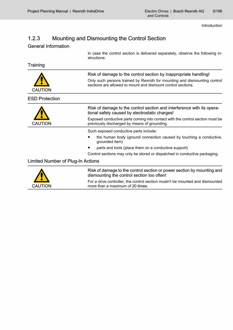
1.2.3 Mounting and Dismounting the Control Section General Information
In case the control section is delivered separately, observe the following in‐structions:
Training
CAUTION
Risk of damage to the control section by inappropriate handling!Only such persons trained by Rexroth for mounting and dismounting controlsections are allowed to mount and dismount control sections.
ESD Protection
CAUTION
Risk of damage to the control section and interference with its opera‐tional safety caused by electrostatic charges!Exposed conductive parts coming into contact with the control section must bepreviously discharged by means of grounding.
Such exposed conductive parts include:● the human body (ground connection caused by touching a conductive,
grounded item)● parts and tools (place them on a conductive support)Control sections may only be stored or dispatched in conductive packaging.
Limited Number of Plug-In Actions
CAUTION
Risk of damage to the control section or power section by mounting anddismounting the control section too often!For a drive controller, the control section mustn't be mounted and dismountedmore than a maximum of 20 times.
Project Planning Manual | Rexroth IndraDrive Electric Drivesand Controls
| Bosch Rexroth AG 5/166
Introduction

Bosch Rexroth AG | Electric Drivesand Controls
Rexroth IndraDrive | Project Planning Manual

2 Important Directions for Use2.1 Appropriate Use2.1.1 Introduction
Rexroth products represent state-of-the-art developments and manufacturing.They are tested prior to delivery to ensure operating safety and reliability.
WARNING
Personal injury and property damage caused by incorrect use of theproducts!The products have been designed for use in the industrial environment and mayonly be used in the appropriate way. If they are not used in the appropriate way,situations resulting in property damage and personal injury can occur.
Rexroth as manufacturer is not liable for any damages resultingfrom inappropriate use. In such cases, the guarantee and the rightto payment of damages resulting from inappropriate use are forfei‐ted. The user alone carries all responsibility of the risks.
Before using Rexroth products, make sure that all the pre-requisites for an ap‐propriate use of the products are satisfied:● Personnel that in any way, shape or form uses our products must first read
and understand the relevant safety instructions and be familiar with ap‐propriate use.
● If the products take the form of hardware, then they must remain in theiroriginal state, in other words, no structural changes are permitted. It is notpermitted to decompile software products or alter source codes.
● Do not mount damaged or faulty products or use them in operation.● Make sure that the products have been installed in the manner described
in the relevant documentation.
2.1.2 Areas of Use and ApplicationDrive controllers made by Rexroth are designed to control electrical motors andmonitor their operation.Control and monitoring of the Drive controllers may require additional sensorsand actors.
The drive controllers may only used with the accessories and partsspecified in this documentation. If a component has not been spe‐cifically named, then it may neither be mounted nor connected. Thesame applies to cables and lines.Operation is only permitted in the specified configurations and com‐binations of components using the software and firmware as speci‐fied in the relevant Functional Descriptions.
Drive controllers have to be programmed before commissioning, making it pos‐sible for the motor to execute the specific functions of an application.Drive controllers of the Rexroth IndraDrive line have been developed for use insingle- and multi-axis drive and control tasks.To ensure application-specific use of Drive controllers, device types of differentdrive power and different interfaces are available.Typical applications include:
Project Planning Manual | Rexroth IndraDrive Electric Drivesand Controls
| Bosch Rexroth AG 7/166
Important Directions for Use

● handling and mounting systems,● packaging and food machines,● printing and paper processing machines and● machine tools.Drive controllers may only be operated under the assembly and installationconditions described in this documentation, in the specified position of normaluse and under the ambient conditions as described (temperature, degree ofprotection, humidity, EMC, etc.).
2.2 Inappropriate UseUsing the Drive controllers outside of the operating conditions described in thisdocumentation and outside of the indicated technical data and specifications isdefined as "inappropriate use".Drive controllers must not be used, if …● they are subject to operating conditions that do not meet the specified
ambient conditions. This includes, for example, operation under water,under extreme temperature fluctuations or extremely high maximum tem‐peratures.
● Furthermore, Drive controllers must not be used in applications whichhave not been expressly authorized by Rexroth. Please carefully followthe specifications outlined in the general Safety Instructions!
8/166 Bosch Rexroth AG | Electric Drivesand Controls
Rexroth IndraDrive | Project Planning Manual
Important Directions for Use

3 Safety Instructions for Electric Drives and Controls 3.1 Safety Instructions - General Information3.1.1 Using the Safety Instructions and Passing them on to Others
Do not attempt to install or commission this device without first reading all doc‐umentation provided with the product. Read and understand these safetyinstructions and all user documentation prior to working with the device. If youdo not have the user documentation for the device, contact your responsibleBosch Rexroth sales representative. Ask for these documents to be sent im‐mediately to the person or persons responsible for the safe operation of thedevice.If the device is resold, rented and/or passed on to others in any other form,these safety instructions must be delivered with the device in the official lan‐guage of the user's country.
WARNING
Improper use of these devices, failure to follow the safety instructions inthis document or tampering with the product, including disabling of safe‐ty devices, may result in material damage, bodily harm, electric shockor even death!Observe the safety instructions!
3.1.2 How to Employ the Safety InstructionsRead these instructions before initial commissioning of the equipment in orderto eliminate the risk of bodily harm and/or material damage. Follow these safetyinstructions at all times.● Bosch Rexroth AG is not liable for damages resulting from failure to ob‐
serve the warnings provided in this documentation.● Read the operating, maintenance and safety instructions in your language
before commissioning the machine. If you find that you cannot completelyunderstand the documentation for your product, please ask your supplierto clarify.
● Proper and correct transport, storage, assembly and installation, as wellas care in operation and maintenance, are prerequisites for optimal andsafe operation of this device.
● Only assign trained and qualified persons to work with electrical installa‐tions:– Only persons who are trained and qualified for the use and operation
of the device may work on this device or within its proximity. Thepersons are qualified if they have sufficient knowledge of the assem‐bly, installation and operation of the product, as well as an under‐standing of all warnings and precautionary measures noted in theseinstructions.
– Furthermore, they must be trained, instructed and qualified to switchelectrical circuits and devices on and off in accordance with technicalsafety regulations, to ground them and to mark them according to therequirements of safe work practices. They must have adequate safe‐ty equipment and be trained in first aid.
● Only use spare parts and accessories approved by the manufacturer.
Project Planning Manual | Rexroth IndraDrive Electric Drivesand Controls
| Bosch Rexroth AG 9/166
Safety Instructions for Electric Drives and Controls

● Follow all safety regulations and requirements for the specific applicationas practiced in the country of use.
● The devices have been designed for installation in industrial machinery.● The ambient conditions given in the product documentation must be ob‐
served.● Only use safety-relevant applications that are clearly and explicitly ap‐
proved in the Project Planning Manual. If this is not the case, they areexcluded. Safety-relevant are all such applications which can cause dan‐ger to persons and material damage.
● The information given in the documentation of the product with regard tothe use of the delivered components contains only examples of applica‐tions and suggestions.The machine and installation manufacturer must– make sure that the delivered components are suited for his individual
application and check the information given in this documentationwith regard to the use of the components,
– make sure that his application complies with the applicable safetyregulations and standards and carry out the required measures,modifications and complements.
● Commissioning of the delivered components is only permitted once it issure that the machine or installation in which they are installed complieswith the national regulations, safety specifications and standards of theapplication.
● Operation is only permitted if the national EMC regulations for the appli‐cation are met.
● The instructions for installation in accordance with EMC requirements canbe found in the section on EMC in the respective documentation (ProjectPlanning Manuals of components and system).The machine or installation manufacturer is responsible for compliancewith the limiting values as prescribed in the national regulations.
● Technical data, connection and installation conditions are specified in theproduct documentation and must be followed at all times.
National regulations which the user must take into account● European countries: according to European EN standards● United States of America (USA):
– National Electrical Code (NEC)– National Electrical Manufacturers Association (NEMA), as well as
local engineering regulations– regulations of the National Fire Protection Association (NFPA)
● Canada: Canadian Standards Association (CSA)● Other countries:
– International Organization for Standardization (ISO)– International Electrotechnical Commission (IEC)
3.1.3 Explanation of Warning Symbols and Degrees of Hazard SeriousnessThe safety instructions describe the following degrees of hazard seriousness.The degree of hazard seriousness informs about the consequences resultingfrom non-compliance with the safety instructions:
10/166 Bosch Rexroth AG | Electric Drivesand Controls
Rexroth IndraDrive | Project Planning Manual
Safety Instructions for Electric Drives and Controls

Warning symbol Signal wordDegree of hazard serious‐ness acc. to ANSI Z535.4-2002
Danger Death or severe bodily harmwill occur.
Warning Death or severe bodily harmmay occur.
CautionMinor or moderate bodilyharm or material damagemay occur.
Fig.3-1: Hazard classification (according to ANSI Z 535)
3.1.4 Hazards by Improper Use
DANGER
High electric voltage and high working current! Risk of death or severebodily injury by electric shock!Observe the safety instructions!
DANGER
Dangerous movements! Danger to life, severe bodily harm or materialdamage by unintentional motor movements!Observe the safety instructions!
WARNING
High electric voltage because of incorrect connection! Risk of death orbodily injury by electric shock!Observe the safety instructions!
WARNING
Health hazard for persons with heart pacemakers, metal implants andhearing aids in proximity to electrical equipment!Observe the safety instructions!
CAUTION
Hot surfaces on device housing! Danger of injury! Danger of burns!Observe the safety instructions!
CAUTION
Risk of injury by improper handling! Risk of bodily injury by bruising,shearing, cutting, hitting or improper handling of pressurized lines!Observe the safety instructions!
Project Planning Manual | Rexroth IndraDrive Electric Drivesand Controls
| Bosch Rexroth AG 11/166
Safety Instructions for Electric Drives and Controls

CAUTION
Risk of injury by improper handling of batteries!Observe the safety instructions!
3.2 Instructions with Regard to Specific Dangers3.2.1 Protection Against Contact with Electrical Parts and Housings
This section concerns devices and drive components with voltagesof more than 50 volts.
Contact with parts conducting voltages above 50 volts can cause personaldanger and electric shock. When operating electrical equipment, it is unavoid‐able that some parts of the units conduct dangerous voltage.
DANGER
High electrical voltage! Danger to life, electric shock and severe bodilyinjury!● Only those trained and qualified to work with or on electrical equipment
are permitted to operate, maintain and repair this equipment.● Follow general construction and safety regulations when working on elec‐
trical power installations.● Before switching on the device, the equipment grounding conductor must
have been permanently connected to all electrical equipment in accord‐ance with the connection diagram.
● Do not operate electrical equipment at any time, even for brief measure‐ments or tests, if the equipment grounding conductor is not permanentlyconnected to the mounting points of the components provided for thispurpose.
● Before working with electrical parts with voltage potentials higher than50 V, the device must be disconnected from the mains voltage or powersupply unit. Provide a safeguard to prevent reconnection.
● For electrical drive and filter components, observe the following:Wait 30 minutes after switching off power to allow capacitors to dis‐charge before beginning to work. Measure the electrical voltage on thecapacitors before beginning to work to make sure that the equipment issafe to touch.
● Never touch the electrical connection points of a component while poweris turned on.
● Install the covers and guards provided with the equipment properly beforeswitching the device on. Before switching the equipment on, cover andsafeguard live parts safely to prevent contact with those parts.
● A residual-current-operated circuit-breaker or r.c.d. cannot be used forelectric drives! Indirect contact must be prevented by other means, forexample, by an overcurrent protective device according to the relevantstandards.
● Secure built-in devices from direct touching of electrical parts by providingan external housing, for example a control cabinet.
12/166 Bosch Rexroth AG | Electric Drivesand Controls
Rexroth IndraDrive | Project Planning Manual
Safety Instructions for Electric Drives and Controls

For electrical drive and filter components with voltages of more than50 volts, observe the following additional safety instructions.
DANGER
High housing voltage and high leakage current! Risk of death or bodilyinjury by electric shock!● Before switching on, the housings of all electrical equipment and motors
must be connected or grounded with the equipment grounding conductorto the grounding points. This is also applicable before short tests.
● The equipment grounding conductor of the electrical equipment and thedevices must be non-detachably and permanently connected to the powersupply unit at all times. The leakage current is greater than 3.5 mA.
● Over the total length, use copper wire of a cross section of a minimum of10 mm2 for this equipment grounding connection!
● Before commissioning, also in trial runs, always attach the equipmentgrounding conductor or connect to the ground wire. Otherwise, high vol‐tages may occur at the housing causing electric shock.
3.2.2 Protection Against Electric Shock by Protective Extra-Low VoltageProtective extra-low voltage is used to allow connecting devices with basic in‐sulation to extra-low voltage circuits.All connections and terminals with voltages between 5 and 50 volts at Rexrothproducts are PELV systems. 1) It is therefore allowed to connect devicesequipped with basic insulation (such as programming devices, PCs, notebooks,display units) to these connections and terminals.
WARNING
High electric voltage by incorrect connection! Risk of death or bodilyinjury by electric shock!If extra-low voltage circuits of devices containing voltages and circuits of morethan 50 volts (e.g. the mains connection) are connected to Rexroth products,the connected extra-low voltage circuits must comply with the requirements forPELV. 2)
3.2.3 Protection Against Dangerous MovementsDangerous movements can be caused by faulty control of connected motors.Some common examples are:● improper or wrong wiring of cable connections● incorrect operation of the equipment components● wrong input of parameters before operation● malfunction of sensors, encoders and monitoring devices● defective components● software or firmware errorsThese errors can occur immediately after equipment is switched on or evenafter an unspecified time of trouble-free operation.
1) “Protective Extra-Low Voltage”2) “Protective Extra-Low Voltage”
Project Planning Manual | Rexroth IndraDrive Electric Drivesand Controls
| Bosch Rexroth AG 13/166
Safety Instructions for Electric Drives and Controls

The monitoring in the drive components will normally be sufficient to avoid faultyoperation in the connected drives. Regarding personal safety, especially thedanger of bodily harm and/or material damage, this alone cannot be relied uponto ensure complete safety. Until the integrated monitoring functions becomeeffective, it must be assumed in any case that faulty drive movements will occur.The extent of faulty drive movements depends upon the type of control and thestate of operation.
14/166 Bosch Rexroth AG | Electric Drivesand Controls
Rexroth IndraDrive | Project Planning Manual
Safety Instructions for Electric Drives and Controls

DANGER
Dangerous movements! Danger to life, risk of injury, severe bodily harmor material damage!● For the above reasons, ensure personal safety by means of qualified and
tested higher-level monitoring devices or measures integrated in the in‐stallation.They have to be provided for by the user according to the specific condi‐tions within the installation and a hazard and fault analysis. The safetyregulations applicable for the installation have to be taken into consider‐ation. Unintended machine motion or other malfunction is possible if safetydevices are disabled, bypassed or not activated.
To avoid accidents, bodily harm and/or material damage:● Keep free and clear of the machine’s range of motion and moving parts.
Possible measures to prevent people from accidentally entering themachine’s range of motion:– use safety fences– use safety guards– use protective coverings– install light curtains or light barriers
● Fences and coverings must be strong enough to resist maximum possiblemomentum.
● Mount the emergency stop switch in the immediate reach of the operator.Verify that the emergency stop works before commissioning. Do not op‐erate the device if the emergency stop switch is not working.
● Isolate the drive power connection by means of an emergency stop circuitor use a safety related starting lockout to prevent unintentional start.
● Make sure that the drives are brought to a safe standstill before accessingor entering the danger zone.
● Additionally secure vertical axes against falling or dropping after switchingoff the motor power by, for example:– mechanically securing the vertical axes,– adding an external braking/arrester/clamping mechanism or– ensuring sufficient equilibration of the vertical axes.
● The standard equipment motor brake or an external brake controlled bythe drive controller are not sufficient to guarantee personal safety!
● Disconnect electrical power to the equipment using a master switch andsecure the switch against reconnection for:– maintenance and repair work– cleaning of equipment– long periods of discontinued equipment use
● Prevent the operation of high-frequency, remote control and radio equip‐ment near electronics circuits and supply leads. If the use of such devicescannot be avoided, verify the system and the installation for possible mal‐functions in all possible positions of normal use before initial commission‐ing. If necessary, perform a special electromagnetic compatibility (EMC)test on the installation.
Project Planning Manual | Rexroth IndraDrive Electric Drivesand Controls
| Bosch Rexroth AG 15/166
Safety Instructions for Electric Drives and Controls

3.2.4 Protection Against Magnetic and Electromagnetic Fields During Oper‐ation and Mounting
Magnetic and electromagnetic fields generated by current-carrying conductorsand permanent magnets in motors represent a serious personal danger tothose with heart pacemakers, metal implants and hearing aids.
WARNING
Health hazard for persons with heart pacemakers, metal implants andhearing aids in proximity to electrical equipment!● Persons with heart pacemakers and metal implants are not permitted to
enter following areas:– Areas in which electrical equipment and parts are mounted, being
operated or commissioned.– Areas in which parts of motors with permanent magnets are being
stored, repaired or mounted.● If it is necessary for somebody with a pacemaker to enter such an area,
a doctor must be consulted prior to doing so. The noise immunity of pres‐ent or future implanted heart pacemakers differs greatly so that no generalrules can be given.
● Those with metal implants or metal pieces, as well as with hearing aids,must consult a doctor before they enter the areas described above. Oth‐erwise health hazards may occur.
3.2.5 Protection Against Contact with Hot Parts
CAUTION
Hot surfaces at motor housings, on drive controllers or chokes! Dangerof injury! Danger of burns!● Do not touch surfaces of device housings and chokes in the proximity of
heat sources! Danger of burns!● Do not touch housing surfaces of motors! Danger of burns!● According to the operating conditions, temperatures can be higher than
60 °C, 140 °F during or after operation.● Before accessing motors after having switched them off, let them cool
down for a sufficiently long time. Cooling down can require up to 140 mi‐nutes! Roughly estimated, the time required for cooling down is five timesthe thermal time constant specified in the Technical Data.
● After switching drive controllers or chokes off, wait 15 minutes to allowthem to cool down before touching them.
● Wear safety gloves or do not work at hot surfaces.● For certain applications, the manufacturer of the end product, machine or
installation, according to the respective safety regulations, has to takemeasures to avoid injuries caused by burns in the end application. Thesemeasures can be, for example: warnings, guards (shielding or barrier),technical documentation.
3.2.6 Protection During Handling and MountingIn unfavorable conditions, handling and mounting certain parts and compo‐nents in an improper way can cause injuries.
16/166 Bosch Rexroth AG | Electric Drivesand Controls
Rexroth IndraDrive | Project Planning Manual
Safety Instructions for Electric Drives and Controls

CAUTION
Risk of injury by improper handling! Bodily injury by bruising, shearing,cutting, hitting!● Observe the general construction and safety regulations on handling and
mounting.● Use suitable devices for mounting and transport.● Avoid jamming and bruising by appropriate measures.● Always use suitable tools. Use special tools if specified.● Use lifting equipment and tools in the correct manner.● If necessary, use suitable protective equipment (for example safety gog‐
gles, safety shoes, safety gloves).● Do not stand under hanging loads.● Immediately clean up any spilled liquids because of the danger of skidding.
3.2.7 Battery SafetyBatteries consist of active chemicals enclosed in a solid housing. Therefore,improper handling can cause injury or material damage.
CAUTION
Risk of injury by improper handling!● Do not attempt to reactivate low batteries by heating or other methods (risk
of explosion and cauterization).● Do not recharge the batteries as this may cause leakage or explosion.● Do not throw batteries into open flames.● Do not dismantle batteries.● When replacing the battery/batteries do not damage electrical parts in‐
stalled in the devices.● Only use the battery types specified by the manufacturer.
Environmental protection and disposal! The batteries contained inthe product are considered dangerous goods during land, air, andsea transport (risk of explosion) in the sense of the legal regulations.Dispose of used batteries separate from other waste. Observe thelocal regulations in the country of assembly.
3.2.8 Protection Against Pressurized SystemsAccording to the information given in the Project Planning Manuals, motorscooled with liquid and compressed air, as well as drive controllers, can be par‐tially supplied with externally fed, pressurized media, such as compressed air,hydraulics oil, cooling liquids and cooling lubricating agents. Improper handlingof the connected supply systems, supply lines or connections can cause injuriesor material damage.
Project Planning Manual | Rexroth IndraDrive Electric Drivesand Controls
| Bosch Rexroth AG 17/166
Safety Instructions for Electric Drives and Controls

CAUTION
Risk of injury by improper handling of pressurized lines!● Do not attempt to disconnect, open or cut pressurized lines (risk of explo‐
sion).● Observe the respective manufacturer's operating instructions.● Before dismounting lines, relieve pressure and empty medium.● Use suitable protective equipment (for example safety goggles, safety
shoes, safety gloves).● Immediately clean up any spilled liquids from the floor.
Environmental protection and disposal! The agents used to operatethe product might not be economically friendly. Dispose of ecolog‐ically harmful agents separately from other waste. Observe the localregulations in the country of assembly.
18/166 Bosch Rexroth AG | Electric Drivesand Controls
Rexroth IndraDrive | Project Planning Manual
Safety Instructions for Electric Drives and Controls

4 Identifying the Control Section4.1 Type Plates 4.1.1 General Information
Each drive component is marked by a type designation. There is a type plate attached to all devices.
4.1.2 Type Plates at the Drive Controller
1 power section type plate2 control section type plate3 firmware type plateFig.4-1: Type plates at the drive controller
Project Planning Manual | Rexroth IndraDrive Electric Drivesand Controls
| Bosch Rexroth AG 19/166
Identifying the Control Section
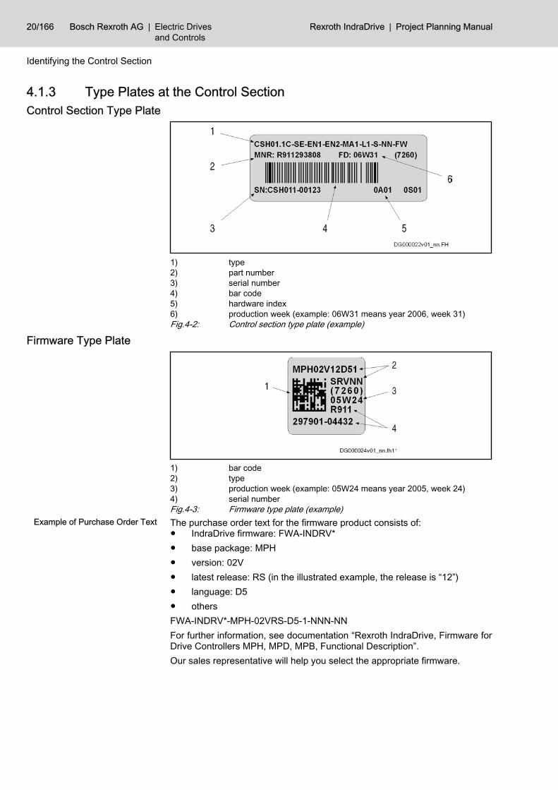
4.1.3 Type Plates at the Control SectionControl Section Type Plate
1) type2) part number3) serial number4) bar code5) hardware index6) production week (example: 06W31 means year 2006, week 31)Fig.4-2: Control section type plate (example)
Firmware Type Plate
1) bar code2) type3) production week (example: 05W24 means year 2005, week 24)4) serial numberFig.4-3: Firmware type plate (example)
Example of Purchase Order Text The purchase order text for the firmware product consists of:● IndraDrive firmware: FWA-INDRV*● base package: MPH● version: 02V● latest release: RS (in the illustrated example, the release is “12”)● language: D5● othersFWA-INDRV*-MPH-02VRS-D5-1-NNN-NNFor further information, see documentation “Rexroth IndraDrive, Firmware forDrive Controllers MPH, MPD, MPB, Functional Description”.Our sales representative will help you select the appropriate firmware.
20/166 Bosch Rexroth AG | Electric Drivesand Controls
Rexroth IndraDrive | Project Planning Manual
Identifying the Control Section

5 Rexroth IndraDrive Control Sections5.1 Overview of TypesControl section range Characteristic Type Features
BASIC BASIC OPEN LOOP CSB01.1N‑FC (Basic 1) not configurable single-axis
BASIC SERCOS CSB01.1N‑SE (Basic 2) not configurable 1) single-axis
BASIC PROFIBUS CSB01.1N‑PB (Basic 3) not configurable 1) single-axis
BASIC Analog CSB01.1N‑AN (Basic 4) not configurable 1) single-axis
BASIC UNIVERSAL BASIC UNIVERSAL CSB01.1C (Basic 5) configurable single-axis
CDB01.1C configurable double-axis
ADVANCED ADVANCED CSH01.1CCSH01.2C
configurable single-axis
1) exception: option L1 (starting lockout) is possibleFig.5-1: Control section overview
5.2 Overview of Functions and Interfaces The control sections differ with regard to ● their configurability● the available interfaces● the cycle times or switching frequencies (pulse frequencies)The table below contains an overview:
CSB01.1N-FC
CSB01.1N-SE
CSB01.1N-PB
CSB01.1N-AN CSB01.1C CDB01.1C
CSH01.1CCSH01.2C
configurable no no no no yes yes yes
configuration slots safetytechnology
0 1 1) 1 1) 1 1) 1 2 1
operation with comfort controlpanel VCP01.2
yes 4) no no no no no no
serial interface RS232 1 1 1 1 1 1 1
Inputs/outputs:
number of dig. inputs, thereof 8 8 8 9 8 22 11
probe type 2 0 1 1 0 1 2 2
probe type 3 0 1 1 0 1 0 0
number of dig. outputs 0 3 3 4 3 4 4
number of analog inputs2 voltage;2 current
0 0 2 0 1 1
number of analog outputs 2 0 0 0 0 2 2
number of relay contacts 1 N/O; 2changeover
switches
1 N/O 1 N/O 1 N/O 1 N/O 1 N/O 1 N/O
Project Planning Manual | Rexroth IndraDrive Electric Drivesand Controls
| Bosch Rexroth AG 21/166
Rexroth IndraDrive Control Sections

CSB01.1N-FC
CSB01.1N-SE
CSB01.1N-PB
CSB01.1N-AN CSB01.1C CDB01.1C
CSH01.1CCSH01.2C
Cycle times 2):
current control 125 µs 125 µs 125 µs 125 µs 125 µs 125 µs 62.5 µs125 µs
velocity control 250 µs500 µs
250 µs500 µs
250 µs500 µs
250 µs500 µs
250 µs500 µs
250 µs500 µs
125 µs250 µs
position control 500 µs1000 µs
500 µs1000 µs
500 µs1000 µs
500 µs1000 µs
500 µs1000 µs
500 µs1000 µs
250 µs500 µs
minimum SERCOS cycle time - 1000 µs - - 1000 µs 1000 µs 250 µs
Switching frequencies 3):
2 kHz ■ ■ ■ ■ ■ ■ ■
4 kHz ■ ■ ■ ■ ■ ■ ■
8 kHz ■ ■ ■ ■ ■ ■ ■
12 kHz - - - - - - ■
16 kHz - - - - - - ■
1) option starting lockout can be configured2) cycle times depend on firmware version3) clock frequencies also depend on power section, see Parameter De‐
scription "P-0-0001, Switching frequency of the power output stage"4) as of firmware version MPB04V12Fig.5-2: Overview of control section functions
For more details on possible configurations see section “OptionalSlots” in the description of the respective control section.
22/166 Bosch Rexroth AG | Electric Drivesand Controls
Rexroth IndraDrive | Project Planning Manual
Rexroth IndraDrive Control Sections

5.3 BASIC Control Sections 5.3.1 Type Codes BASIC and BASIC UNIVERSALType Code BASIC CSB01.1N
Fig.5-3: Type code control section BASIC (single-axis); (to be continued)
Project Planning Manual | Rexroth IndraDrive Electric Drivesand Controls
| Bosch Rexroth AG 23/166
Rexroth IndraDrive Control Sections

Fig.5-4: Type code control section BASIC (single-axis); (continuation)
Type Code BASIC UNIVERSAL Single-Axis CSB01.1CSee type code BASIC CSB01.1N
24/166 Bosch Rexroth AG | Electric Drivesand Controls
Rexroth IndraDrive | Project Planning Manual
Rexroth IndraDrive Control Sections

Type Code BASIC UNIVERSAL Double-Axis CDB01.1C
Fig.5-5: Type code control section BASIC (double-axis); (to be continued)
Project Planning Manual | Rexroth IndraDrive Electric Drivesand Controls
| Bosch Rexroth AG 25/166
Rexroth IndraDrive Control Sections

Fig.5-6: Type code control section BASIC (double-axis); (continuation)
26/166 Bosch Rexroth AG | Electric Drivesand Controls
Rexroth IndraDrive | Project Planning Manual
Rexroth IndraDrive Control Sections

5.3.2 Dimensions BASICDimensions BASIC and BASIC UNIVERSAL Single-Axis
Fig.5-7: Dimensions CSB
For the mounting dimensions in the front area, please see themounting dimensions of the drive controllers.
Project Planning Manual | Rexroth IndraDrive Electric Drivesand Controls
| Bosch Rexroth AG 27/166
Rexroth IndraDrive Control Sections

Dimensions BASIC UNIVERSAL Double-Axis
Fig.5-8: Dimensions CDB
For the mounting dimensions in the front area, please see themounting dimensions of the drive controllers.
28/166 Bosch Rexroth AG | Electric Drivesand Controls
Rexroth IndraDrive | Project Planning Manual
Rexroth IndraDrive Control Sections

5.3.3 CSB01.1N-FC - BASIC OPENLOOP Front View with Connections at Basic Circuit Board
Front view Connectionpoint
Strandedwire
[mm²]
AWG Tighten‐ing tor‐
que[Nm]
Description
X31 / X32 0,08–1,5 28–14 - digital and analog in‐puts/outputs; voltage
input (24V, 0V)
X11 / X12 0,08–1,5 28–14 - relay contacts
X35 / X36 0,08–1,5 28–14 - analog inputs / outputs;voltage output (24V,
0V)
X2 0,25–0,5 - - serial interface
H1 - - - interface for controlpanel
Fig.5-9: Connections BASIC OPENLOOP
Functions
The specified factory settings apply to firmware MPx04.For additional notes on function and commissioning, see the fol‐lowing sections in the Functional Description of the firmware:● Analog Outputs● Analog Inputs● Digital Inputs/Outputs
Project Planning Manual | Rexroth IndraDrive Electric Drivesand Controls
| Bosch Rexroth AG 29/166
Rexroth IndraDrive Control Sections

Function Con‐nection
Factory setting Nominal data Figure;technical data
power consumption from 24V supply;connection at power section X13 or +24V/0V
- - see section “Power Consumption”
relay contact Rel3
no Rel 3 X11.3 speed reachedS‑0‑0013
AC 250 V2 A
DC 30 V1 A
X11 I X12
data see chapter7.1 Relay Contacts ,
page 139
com Rel 3 X11.4
nc Rel 3 X11.5
relay contact Rel2
no Rel 2 X12.3 ready signalP‑0‑0115
AC 250 V2 A
DC 30 V1 A
com Rel 2 X12.4
nc Rel 2 X12.5
relay contact Rel1
no Rel 1 X12.1 ready for operationP‑0‑0115
AC 250 V2 A
DC 30 V1 A
no Rel 1 X12.2
digitalinputs
I_1 X31.3 clear errorS‑0‑0099
24 V3 mA
X31 I X32
data see chapter7.2 Digital Inputs/Out‐
puts, page 140
I_2 X31.4 drive ONP‑0‑4028
I_3 X31.5 velocity cmd valuefrom memory of
fixed valuesP‑0‑1200
I_4 X31.6 velocity cmd valuefrom memory of
fixed valuesP‑0‑1200
I_5 X31.7 velocity cmd valuefrom memory of
fixed valuesP‑0‑1200
I/O_8 X32.6 E-StopP‑0‑0223
I/O_9 X32.7 velocity cmd valuefrom memory of
fixed valuesP‑0‑1200
I/O_10 X32.8 velocity cmd valuefrom memory of
fixed valuesP‑0‑1200
30/166 Bosch Rexroth AG | Electric Drivesand Controls
Rexroth IndraDrive | Project Planning Manual
Rexroth IndraDrive Control Sections

Function Con‐nection
Factory setting Nominal data Figure;technical data
analoginputs
voltage input I_a_1+ X32.4 ±10 V X31 I X32
data see chapter Ana‐log Input Type 1 , page
145
I_a_1- X32.5
voltage input I_a_2+ X32.1
I_a_2- X32.2
current input I_ai3+ X36.1 0…20 mA X35 I X36
data see chapter Ana‐log Input Type 3 , page
146
I_ai3- X36.2
current input I_ai4+ X36.3
I_ai4- X36.4
analogoutput
voltage output O_a_1 X32.9 0…+10 V X31 I X32
data see chapter Ana‐log Output Type 1 ,
page 148
reference potentialfor analog voltage
output
GND_a X32.3
analogoutput
voltage output O_a_2 X35.3 0…+10 V X35 I X36
data see chapter Ana‐log Output Type 1 ,
page 148
reference potentialfor analog voltage
output
GND_a X35.4
Project Planning Manual | Rexroth IndraDrive Electric Drivesand Controls
| Bosch Rexroth AG 31/166
Rexroth IndraDrive Control Sections

Function Con‐nection
Factory setting Nominal data Figure;technical data
input for powersupply of digital
inputs
supply of digital in‐puts
+24V X31.8 X31 I X32
DC 19…30 V; max.0.1 A
0V X31.9
output (source)for power supplyof digital inputs
connect supply(source) of digital in‐
puts to X31.8 orX31.9
+24V X35.1 X35 I X36
DC 19…30 V; max.0.1 A; protected againstpolarity reversal; short-
circuit proof
0V X35.2
serial interface X2 correspondsto RS232
data see chapter7.4 X2, Serial Interface
(RS232) , page 149
Fig.5-10: Functions BASIC OPENLOOP
32/166 Bosch Rexroth AG | Electric Drivesand Controls
Rexroth IndraDrive | Project Planning Manual
Rexroth IndraDrive Control Sections

5.3.4 CSB01.1N-SE - BASIC SERCOS Front View with Connections
Front view Connectionpoint
Strandedwire
[mm²]
AWG Tighten‐ing tor‐
que[Nm]
Description
X8 0,25–0,5 - - encoder evaluationENS
X31 /X32
0,08–1,5 28–14 - digital inputs/outputs;voltage input (24V, 0V)
X41 0,25–0,5 - optional: starting lock‐out
X20 /X21
0,3 master communicationSERCOS
X2 0,25–0,5 - - serial interface
H1 - - - interface for controlpanel
Fig.5-11: Connections BASIC SERCOS
Functions
The specified factory settings apply to firmware MPx04.For additional notes on function and commissioning, see the fol‐lowing sections in the Functional Description of the firmware:● Analog Outputs● Analog Inputs● Digital Inputs/Outputs
Project Planning Manual | Rexroth IndraDrive Electric Drivesand Controls
| Bosch Rexroth AG 33/166
Rexroth IndraDrive Control Sections

External supply required!Digital I/Os require external supply voltage at X31.8 and X31.9.Use protective diode!Protect the module against incorrect connection and polarity rever‐sal of the supply voltage, e.g. by using a protective diode (see D3in figure below) in the power supply at X31.8.Configuration is possible as input or output!Observe that the connections X32.6, X32.7, X32.8 can be config‐ured as digital inputs or outputs (I/O_8, I/O_9, I/O_10). At CDB01and CSH01 control sections, additionally X32.9 as I/O_11.
D1, D2 diodes, internalD3 protective diode, externalLT power sectionBR circuit for motor holding brakeST control sectionOM1 optional modulesOM2 optional modules with supply voltage connection, e.g. MA1, MD2Fig.5-12: Block diagram 24V supply
34/166 Bosch Rexroth AG | Electric Drivesand Controls
Rexroth IndraDrive | Project Planning Manual
Rexroth IndraDrive Control Sections

Function Con‐nection
Factory setting Nominal data Figure;technical data
power consumption from 24V supply;connection at power section X13 or +24V/0V
- - see section “Power Consumption”
master commu‐nication
SERCOS SE X20;X21
max.16 MBaud
data see chapter6.2.1 SE - SERCOS ,
page 88
encoder interfa‐ces
ENS X8 DC 11.6 V300 mA
data see chapter6.3.1 ENS - StandardEncoder Evaluation ,
page 104
relay contact Rel 1 X31.1 ready for operationP‑0‑0115
DC 24 V1 A
X31 I X32
data see chapter7.1 Relay Contacts ,
page 139
Rel 1 X31.2
Project Planning Manual | Rexroth IndraDrive Electric Drivesand Controls
| Bosch Rexroth AG 35/166
Rexroth IndraDrive Control Sections

Function Con‐nection
Factory setting Nominal data Figure;technical data
digitalinputs
I_1type 2(probe)
X31.3 probe 1S‑0‑0401
can be con‐figured as
probe24 V3 mA
typ. 1 µs
X31 I X32
data see chapter7.2 Digital Inputs/Out‐
puts, page 140
I_2type 3(probe)
X31.4 24 V3 mA
I_3 X31.5 travel range limitswitch
P‑0‑0222
I_4 X31.6 travel range limitswitch
P‑0‑0222
I_5 X31.7 home switchS‑0‑0400
I/O_8 X32.6 E-StopP‑0‑0223
I/O_9 X32.7 combined I/O con‐figured as input I/
O_9; see alsoP‑0‑0302
I/O_10 X32.8 combined I/O con‐figured as input I/O_10; see also
P‑0‑0302
digitaloutputs
I/O_8 X32.6 combined I/O con‐figured as input I/
O_8; see alsoP‑0‑0302
24 V0.5 A
X31 I X32
data see chapter7.2.3 Digital Outputs ,
page 143
I/O_9 X32.7 combined I/O con‐figured as input I/
O_9; see alsoP‑0‑0302
I/O_10 X32.8 combined I/O con‐figured as input I/O_10; see also
P‑0‑0302
36/166 Bosch Rexroth AG | Electric Drivesand Controls
Rexroth IndraDrive | Project Planning Manual
Rexroth IndraDrive Control Sections

Function Con‐nection
Factory setting Nominal data Figure;technical data
power supply ofdigital inputs/out‐
puts
+24V X31.8 X31 I X32
DC 19…30 V; max.1.1 A
see note on “protectivediode”
0V X31.9
serial interface RS232 X2
data see chapter7.4 X2, Serial Interface
(RS232) , page 149
optional: startinglockout
X41
data see chapter6.5.1 L1 - Starting Lock‐
out , page 134
Fig.5-13: Functions BASIC SERCOS
Project Planning Manual | Rexroth IndraDrive Electric Drivesand Controls
| Bosch Rexroth AG 37/166
Rexroth IndraDrive Control Sections

5.3.5 CSB01.1N-PB - BASIC PROFIBUS Front View with Connections
Front view Connectionpoint
Strandedwire
[mm²]
AWG Tighten‐ing tor‐
que[Nm]
Description
X8 0,25–0,5 - - encoder evaluationENS
X31 / X32 0,08–1,5 28–14 - digital inputs/outputs;voltage input (24V, 0V)
X41 0,25–0,5 - optional: starting lock‐out
X30 0,08–0,5 - - master communicationPROFIBUS
X2 0,25–0,5 n.s. - serial interface
H1 - - - interface for controlpanel
Fig.5-14: Connections BASIC PROFIBUS
Functions
The specified factory settings apply to firmware MPx04.For additional notes on function and commissioning, see the fol‐lowing sections in the Functional Description of the firmware:● Analog Outputs● Analog Inputs● Digital Inputs/Outputs
38/166 Bosch Rexroth AG | Electric Drivesand Controls
Rexroth IndraDrive | Project Planning Manual
Rexroth IndraDrive Control Sections

External supply required!Digital I/Os require external supply voltage at X31.8 and X31.9.Use protective diode!Protect the module against incorrect connection and polarity rever‐sal of the supply voltage, e.g. by using a protective diode (see D3in figure below) in the power supply at X31.8.Configuration is possible as input or output!Observe that the connections X32.6, X32.7, X32.8 can be config‐ured as digital inputs or outputs (I/O_8, I/O_9, I/O_10). At CDB01and CSH01 control sections, additionally X32.9 as I/O_11.
D1, D2 diodes, internalD3 protective diode, externalLT power sectionBR circuit for motor holding brakeST control sectionOM1 optional modulesOM2 optional modules with supply voltage connection, e.g. MA1, MD2Fig.5-15: Block diagram 24V supply
Function Con‐nection
Factory setting Nominal data Figure;technical data
power consumption from 24V supply;connection at power section X13 or +24V/0V
- - see section “Power Consumption”
master commu‐nication
PROFIBUS PB X30 12 MBaud
Project Planning Manual | Rexroth IndraDrive Electric Drivesand Controls
| Bosch Rexroth AG 39/166
Rexroth IndraDrive Control Sections

Function Con‐nection
Factory setting Nominal data Figure;technical data
encoder interfa‐ces
ENS X8 DC 11.6 V300 mA
data see chapter6.3.1 ENS - StandardEncoder Evaluation ,
page 104
relay contact Rel 1 X31.1 ready for operationP‑0‑0115
DC 24 V1 A
X31 I X32
data see chapter7.1 Relay Contacts ,
page 139
Rel 1 X31.2
40/166 Bosch Rexroth AG | Electric Drivesand Controls
Rexroth IndraDrive | Project Planning Manual
Rexroth IndraDrive Control Sections

Function Con‐nection
Factory setting Nominal data Figure;technical data
digital inputs I_1type 2(probe)
X31.3 probe 1S‑0‑0401
can be con‐figured as
probe24 V3 mA
typ. 1 µs
X31 I X32
data see chapter7.2 Digital Inputs/Out‐
puts, page 140
I_2type 3(probe)
X31.4 24 V3 mA
X31 I X32
data see chapter7.2 Digital Inputs/Out‐
puts, page 140
I_3 X31.5 travel range limitswitch
P‑0‑0222
I_4 X31.6 travel range limitswitch
P‑0‑0222
I_5 X31.7 home switchS‑0‑0400
I/O_8 X32.6 E-StopP‑0‑0223
I/O_9 X32.7 combined I/O con‐figured as input I/
O_9; see alsoP‑0‑0302
I/O_10 X32.8 combined I/O con‐figured as input I/O_10; see also
P‑0‑0302
digital outputs I/O_8 X32.6 combined I/O con‐figured as input I/
O_8; see alsoP-0-0302
24 V0.5 A
X31 I X32
data see chapter7.2.3 Digital Outputs ,
page 143
I/O_9 X32.7 combined I/O con‐figured as input I/
O_9; see alsoP‑0‑0302
I/O_10 X32.8 combined I/O con‐figured as input I/O_10; see also
P‑0‑0302
Project Planning Manual | Rexroth IndraDrive Electric Drivesand Controls
| Bosch Rexroth AG 41/166
Rexroth IndraDrive Control Sections

Function Con‐nection
Factory setting Nominal data Figure;technical data
power supply ofdigital inputs/out‐
puts
power supply of digi‐tal inputs/outputs
+24V X31.8 X31 I X32
DC 19…30 V; max.1.1 A
see note on “protectivediode”
0V X31.9
serial interface RS232 X2
serial interfacedata see chapter
7.4 X2, Serial Interface(RS232) , page 149
optional: startinglockout
X41
data see chapter6.5.1 L1 - Starting Lock‐
out , page 134
Fig.5-16: Functions BASIC PROFIBUS
42/166 Bosch Rexroth AG | Electric Drivesand Controls
Rexroth IndraDrive | Project Planning Manual
Rexroth IndraDrive Control Sections

5.3.6 CSB01.1N-AN - BASIC ANALOG Front View with Connections
Front view Connectionpoint
Strandedwire
[mm²]
AWG Tighten‐ing tor‐
que[Nm]
Description
X8 0,25–0,5 - - encoder evaluationENS
X31 / X32 0,08–1,5 28–14 - digital and analog in‐puts/outputs; voltage
input (24V, 0V)
X41 0,25–0,5 - optional: starting lock‐out
X16 0,25–0,5 - - encoder emulationMEM
X2 0,25–0,5 n.s. - serial interface
H1 - - - interface for controlpanel
Fig.5-17: Connections BASIC ANALOG
Functions
The specified factory settings apply to firmware MPx04.For additional notes on function and commissioning, see the fol‐lowing sections in the Functional Description of the firmware:● Analog Outputs● Analog Inputs● Digital Inputs/Outputs
Project Planning Manual | Rexroth IndraDrive Electric Drivesand Controls
| Bosch Rexroth AG 43/166
Rexroth IndraDrive Control Sections

External supply required!Digital I/Os require external supply voltage at X31.8 and X31.9.Use protective diode!Protect the module against incorrect connection and polarity rever‐sal of the supply voltage, e.g. by using a protective diode (see D3in figure below) in the power supply at X31.8.Configuration is possible as input or output!Observe that the connections X32.6, X32.7, X32.8 can be config‐ured as digital inputs or outputs (I/O_8, I/O_9, I/O_10). At CDB01and CSH01 control sections, additionally X32.9 as I/O_11.
D1, D2 diodes, internalD3 protective diode, externalLT power sectionBR circuit for motor holding brakeST control sectionOM1 optional modulesOM2 optional modules with supply voltage connection, e.g. MA1, MD2Fig.5-18: Block diagram 24V supply
44/166 Bosch Rexroth AG | Electric Drivesand Controls
Rexroth IndraDrive | Project Planning Manual
Rexroth IndraDrive Control Sections

Function Con‐nection
Factory setting Nominal data Figure;technical data
power consumption from 24V supply;connection at power section X13 or +24V/0V
- - see section “Power Consumption”
relay contact Rel 1 X31.1 ready for operationP‑0‑0115
DC 24 V1 A
X31 I X32
data see chapter7.1 Relay Contacts ,
page 139
Rel 1 X31.2
digitalinputs
I_1 X31.3 clear errorS‑0‑0099
24 V3 mA
X31 I X32
data see chapter7.2 Digital Inputs/Out‐
puts, page 140
I_2 X31.4 drive ONP‑0‑4028
I_3 X31.5 travel range limitswitch
P‑0‑0222
I_4 X31.6 travel range limitswitch
P‑0‑0222
I_5 X31.7 home switchS‑0‑0400
I/O_8 X32.6 E-StopP‑0‑0223
I/O_9 X32.7 Drive HaltP‑0‑4028
I/O_10 X32.8 combined I/O con‐figured as output I/
O_10; see alsoP‑0‑0302
I/O_11 X32.9 combined I/O con‐figured as output I/
O_11; see alsoP‑0‑0302
Project Planning Manual | Rexroth IndraDrive Electric Drivesand Controls
| Bosch Rexroth AG 45/166
Rexroth IndraDrive Control Sections

Function Con‐nection
Factory setting Nominal data Figure;technical data
digitaloutputs
I/O_8 X32.6 combined I/O con‐figured as input I/
O_8; see alsoP‑0‑0302
24 V0.5 A
X31 I X32
data see chapter7.2.3 Digital Outputs ,
page 143
I/O_9 X32.7 combined I/O con‐figured as input I/
O_9; see alsoP‑0‑0302
I/O_10 X32.8 ready signalP‑0‑0115
I/O_11 X32.9 warningP‑0‑0115
analoginputs
voltage input I_a_1+ X32.4 ±10 V X31 I X32
data see chapter Ana‐log Input Type 1 , page
145example of connectionsee chapter 7-16Shieldconnection X32, page
144
I_a_1- X32.5
voltage input I_a_2+ X32.1
I_a_2- X32.2
reference potentialfor analog inputs
connection for signalshields
GND_a X32.3
power supply ofdigital inputs/out‐
puts
+24V X31.8 X31 I X32
DC 19…30 V;max. 1.1 A
see note on “protectivediode”
0V X31.9
46/166 Bosch Rexroth AG | Electric Drivesand Controls
Rexroth IndraDrive | Project Planning Manual
Rexroth IndraDrive Control Sections

Function Con‐nection
Factory setting Nominal data Figure;technical data
serial interface RS232 X2
data see chapter7.4 X2, Serial Interface
(RS232) , page 149
encoder interfa‐ces
ENS X8 DC 11.6 V300 mA
data see chapter6.3.1 ENS - StandardEncoder Evaluation ,
page 104
encoder emula‐tion
MEM X16
optional: startinglockout
X41
data see chapter6.5.1 L1 - Starting Lock‐
out , page 134
Fig.5-19: Functions BASIC ANALOG
Project Planning Manual | Rexroth IndraDrive Electric Drivesand Controls
| Bosch Rexroth AG 47/166
Rexroth IndraDrive Control Sections

5.3.7 CSB01.1C - BASIC UNIVERSAL Single-Axis Front View with Connections
Front view Connectionpoint
Strandedwire
[mm²]
AWG Tighten‐ing tor‐
que[Nm]
Description
X8 0,25–0,5 - - encoder evaluationENS
option 2
X31 / X32 0,08–1,5 28–14 - digital inputs/outputs;voltage input (24V, 0V)
X7 memory card slot
option ST 1)
option MC 2)
X2 0,25–0,5 - - serial interface
H1 - - - interface for controlpanel
1) option ST = safety technology2) option MC = master communicationFig.5-20: Connections BASIC UNIVERSAL single-axis CSB01.1C
Functions
The specified factory settings apply to firmware MPx04.For additional notes on function and commissioning, see the fol‐lowing sections in the Functional Description of the firmware:● Analog Outputs● Analog Inputs● Digital Inputs/Outputs
48/166 Bosch Rexroth AG | Electric Drivesand Controls
Rexroth IndraDrive | Project Planning Manual
Rexroth IndraDrive Control Sections

External supply required!Digital I/Os require external supply voltage at X31.8 and X31.9.Use protective diode!Protect the module against incorrect connection and polarity rever‐sal of the supply voltage, e.g. by using a protective diode (see D3in figure below) in the power supply at X31.8.Configuration is possible as input or output!Observe that the connections X32.6, X32.7, X32.8 can be config‐ured as digital inputs or outputs (I/O_8, I/O_9, I/O_10). At CDB01and CSH01 control sections, additionally X32.9 as I/O_11.
D1, D2 diodes, internalD3 protective diode, externalLT power sectionBR circuit for motor holding brakeST control sectionOM1 optional modulesOM2 optional modules with supply voltage connection, e.g. MA1, MD2Fig.5-21: Block diagram 24V supply
Function Con‐nection
Factory setting Nominal data Figure;technical data
power consumption from 24V supply;connection at power section X13 or +24V/0V
- - see section “Power Consumption”
master commu‐nication
configurable
Project Planning Manual | Rexroth IndraDrive Electric Drivesand Controls
| Bosch Rexroth AG 49/166
Rexroth IndraDrive Control Sections

Function Con‐nection
Factory setting Nominal data Figure;technical data
encoder interfa‐ces
ENS X8 DC 11.6 V300 mA
data see chapter6.3.1 ENS - StandardEncoder Evaluation ,
page 104
relay contact Rel 1 X31.1 ready for operationP‑0‑0115
DC 24 V1 A
X31 I X32
data see chapter7.1 Relay Contacts ,
page 139
Rel 1 X31.2
50/166 Bosch Rexroth AG | Electric Drivesand Controls
Rexroth IndraDrive | Project Planning Manual
Rexroth IndraDrive Control Sections

Function Con‐nection
Factory setting Nominal data Figure;technical data
digitalinputs
I_1type 2(probe)
X31.3 probe 1S‑0‑0401
can be con‐figured as
probe24 V3 mA
typ. 1 µs
X31 I X32
data see chapter7.2 Digital Inputs/Out‐
puts, page 140
I_2type 3(probe)
X31.4 24 V3 mA
I_3 X31.5 travel range limitswitch
P‑0‑0222
I_4 X31.6 travel range limitswitch
P‑0‑0222
I_5 X31.7 home switchS‑0‑0400
I/O_8 X32.6 E-StopP‑0‑0223
I/O_9 X32.7 combined I/O con‐figured as input I/
O_9; see alsoP‑0‑0302
I/O_10 X32.8 combined I/O con‐figured as input I/O_10; see also
P‑0‑0302
digitaloutputs
I/O_8 X32.6 combined I/O con‐figured as input I/
O_8; see alsoP‑0‑0302
24 V0.5 A
X31 I X32
data see chapter7.2.3 Digital Outputs ,
page 143
I/O_9 X32.7 combined I/O con‐figured as input I/
O_9; see alsoP‑0‑0302
I/O_10 X32.8 combined I/O con‐figured as input I/O_10; see also
P‑0‑0302
Project Planning Manual | Rexroth IndraDrive Electric Drivesand Controls
| Bosch Rexroth AG 51/166
Rexroth IndraDrive Control Sections

Function Con‐nection
Factory setting Nominal data Figure;technical data
power supply ofdigital inputs/out‐
puts
+24V X31.8 X31 I X32
DC 19…30 Vmax. 1.1 A
see note on “protectivediode”
0V X31.9
serial interface RS232 X2
data see chapter7.4 X2, Serial Interface
(RS232) , page 149
optional func‐tions
allowed options: seeconfiguration table
see corresponding op‐tional module
Fig.5-22: Functions BASIC UNIVERSAL single-axis CSB01.1C
52/166 Bosch Rexroth AG | Electric Drivesand Controls
Rexroth IndraDrive | Project Planning Manual
Rexroth IndraDrive Control Sections

Optional Slots
option MC master communicationoption ST safety technologyFig.5-23: Optional slots for BASIC UNIVERSAL single-axis CSB01.1C
The following configuration table shows which optional module issupported on which optional slot.Our sales representative will inform you on whether a certain com‐bination is allowed or not.
Optional mod‐ule Optional slot
option MC option 1 (onboard)
option 2 option ST(X41)
memory card slot(X7)
control panel(H1)
SE ■ - - - - -
PB ■ - - - - -
PL ■ - - - - -
Project Planning Manual | Rexroth IndraDrive Electric Drivesand Controls
| Bosch Rexroth AG 53/166
Rexroth IndraDrive Control Sections

Optional mod‐ule Optional slot
option MC option 1 (onboard)
option 2 option ST(X41)
memory card slot(X7)
control panel(H1)
CO ■ - - - - -
ET ■ - - - - -
S3 ■ - - - - -
CCD - - - - - -
ENS - ■ ■ - - -
EN1 - - ■ - - -
EN2 - - ■ - - -
MEM - - ■ - - -
MA1 - - ■ - - -
MD1 - - - - - -
MD2 - - - - - -
L1 - - - ■ - -
S1 - - - - - -
S - - - - - ■
PFM02 - - - - ■ -
■ allowed optional module on optional slot- not allowedFig.5-24: Configuration table
54/166 Bosch Rexroth AG | Electric Drivesand Controls
Rexroth IndraDrive | Project Planning Manual
Rexroth IndraDrive Control Sections

5.3.8 CDB01.1C - BASIC UNIVERSAL Double-Axis Front View with Connections
Front view Connectionpoint
Strandedwire
[mm²]
AWG Tighten‐ing tor‐
que[Nm]
Description
X7 memory card slot
option 3
option 4
X33; X34 0,08–1,5 28–14 - digital inputs
option 1
option 2
X31; X32 0,08–1,5 28–14 - digital and analog in‐puts/outputs; voltage
input (24V, 0V)
option ST1 1)
option ST2 1)
option MC 2)
X2 0,25–0,5 - - serial interface
H1 - - - interface for controlpanel
1) option ST = safety technology2) option MC = master communicationFig.5-25: Connections BASIC UNIVERSAL double-axis
Project Planning Manual | Rexroth IndraDrive Electric Drivesand Controls
| Bosch Rexroth AG 55/166
Rexroth IndraDrive Control Sections

Functions
The specified factory settings apply to firmware MPx04.For additional notes on function and commissioning, see the fol‐lowing sections in the Functional Description of the firmware:● Analog Outputs● Analog Inputs● Digital Inputs/Outputs
External supply required!Digital I/Os require external supply voltage at X31.8 and X31.9.Use protective diode!Protect the module against incorrect connection and polarity rever‐sal of the supply voltage, e.g. by using a protective diode (see D3in figure below) in the power supply at X31.8.Configuration is possible as input or output!Observe that the connections X32.6, X32.7, X32.8 can be config‐ured as digital inputs or outputs (I/O_8, I/O_9, I/O_10). At CDB01and CSH01 control sections, additionally X32.9 as I/O_11.
D1, D2 diodes, internalD3 protective diode, externalLT power sectionBR circuit for motor holding brakeST control sectionOM1 optional modulesOM2 optional modules with supply voltage connection, e.g. MA1, MD2Fig.5-26: Block diagram 24V supply
56/166 Bosch Rexroth AG | Electric Drivesand Controls
Rexroth IndraDrive | Project Planning Manual
Rexroth IndraDrive Control Sections

Low input resistanceThe digital inputs I_6 and I_7 are mounted in parallel to the analoginput I_a_1. Observe that this reduces the input resistance of theanalog input to the value of the digital inputs.Signal sources with low impedance for a low degree of linearity errorIf you need a low degree of linearity error, use signal sources withthe lowest possible impedance at the analog input I_a_1. For ex‐ample, you can achieve a linearity error smaller 5% with a 1 kohmpotentiometer and smaller 2.5% with a 500 ohm potentiometer.
Function Con‐nection
Factory setting Nominal data Figure;technical data
power consumption from 24V supply;connection at power section X13 or +24V/0V
- - see section “Power Consumption”
master commu‐nication
configurable
relay contact Rel 1 X31.1 ready for operationP‑0‑0115
DC 24 V1 A
X31 I X32
data see chapter7.1 Relay Contacts ,
page 139
Rel 1 X31.2
Project Planning Manual | Rexroth IndraDrive Electric Drivesand Controls
| Bosch Rexroth AG 57/166
Rexroth IndraDrive Control Sections

Function Con‐nection
Factory setting Nominal data Figure;technical data
digitalinputs
I_1type 2(probe)
X31.3 axis 1: probe 1S‑0‑0401
can be con‐figured as
probe;24 V3 mA
typ. 1 µs
X31 I X32
data see chapter7.2 Digital Inputs/Out‐
puts, page 140
I_2type 2(probe)
X31.4 axis 2: probe 1S‑0‑0401
I_3 X31.5 axis 1: travel rangelimit switchP‑0‑0222
24 V3 mA
I_4 X31.6 axis 1: travel rangelimit switchP‑0‑0222
I_5 X31.7 axis 1: home switchS‑0‑0400
I_6 X32.4 can also be used asanalog input; see
I_a_1+
I_7 X32.5 can also be used asanalog input; see
I_a_1-
Fig.5-27: Functions BASIC UNIVERSAL double-axis CDB01.1C
58/166 Bosch Rexroth AG | Electric Drivesand Controls
Rexroth IndraDrive | Project Planning Manual
Rexroth IndraDrive Control Sections

Function Con‐nection
Factory setting Nominal data Figure;technical data
I/O_8 X32.6 axis 1: E-StopP‑0‑0223
X31 I X32
X33 I X34
I/O_9 X32.7 axis 2: travel rangelimit switchP‑0‑0222
I/O_10 X32.8 axis 2: travel rangelimit switchP‑0‑0222
I/O_11 X32.9 axis 2: home switchS‑0‑0400
I_12 X33.1
I_13 X33.2
I_14 X33.3
I_15 X33.4
I_16 X33.5
I_17 X33.6
I_18 X34.1
I_19 X34.2
I_20 X34.3
I_21 X34.4
I_22 X34.5
reference potentialfor digital inputs
0V X34.6
digitaloutputs
I/O_8 X32.6 combined I/O con‐figured as input I/
O_8; see alsoP‑0‑0302
24 V0.5 A
X31 I X32
data see chapter7.2.3 Digital Outputs ,
page 143
I/O_9 X32.7 combined I/O con‐figured as input I/
O_9; see alsoP‑0‑0302
I/O_10 X32.8 combined I/O con‐figured as input I/O_10; see also
P‑0‑0302
I/O_11 X32.9 combined I/O con‐figured as input I/O_11; see also
P‑0‑0302
Project Planning Manual | Rexroth IndraDrive Electric Drivesand Controls
| Bosch Rexroth AG 59/166
Rexroth IndraDrive Control Sections

Function Con‐nection
Factory setting Nominal data Figure;technical data
analoginputs
voltage input I_a_1+ X32.4 can also be used asdigital input I_6
±10 Vtyp. 2 kohm
X31 I X32
data see chapter Ana‐log Input Type 4 , page
147example of connectionsee chapter 7-16Shieldconnection X32, page
144
I_a_1- X32.5 can also be used asdigital input I_7
analogoutputs
voltage output O_a_1 X32.1 5 V1 mA
X31 I X32
data see chapter Ana‐log Output Type 2 ,
page 148example of connectionsee chapter 7-16Shieldconnection X32, page
144
O_a_2 X32.2
reference potentialfor analog voltage
output
connection for signalshields
GND_a X32.3
power supply ofdigital inputs/out‐
puts
+24V X31.8 X31 I X32
DC 19…30 V; max.1.1 A
see note on “protectivediode”
0V X31.9
60/166 Bosch Rexroth AG | Electric Drivesand Controls
Rexroth IndraDrive | Project Planning Manual
Rexroth IndraDrive Control Sections

Function Con‐nection
Factory setting Nominal data Figure;technical data
serial interface RS232 X2
data see chapter7.4 X2, Serial Interface
(RS232) , page 149
optional func‐tions
allowed options: seeconfiguration table
see corresponding op‐tional module
Fig.5-28: Functions BASIC UNIVERSAL double-axis CDB01.1C
Project Planning Manual | Rexroth IndraDrive Electric Drivesand Controls
| Bosch Rexroth AG 61/166
Rexroth IndraDrive Control Sections

Optional Slots
option MC master communicationoptions ST1and ST2
safety technology
Fig.5-29: Options for BASIC UNIVERSAL double-axis CDB01.1C
The following configuration table shows which optional module issupported on which optional slot.Our sales representative will inform you on whether a certain com‐bination is allowed or not.
62/166 Bosch Rexroth AG | Electric Drivesand Controls
Rexroth IndraDrive | Project Planning Manual
Rexroth IndraDrive Control Sections

Optionalmodule Optional slot
optionMC
option 1 option 2 option 3(X8.1)
option 4(X8.2)
option ST1
(X41.1)
option ST2
(X41.2)
memory cardslot(X7)
controlpanel (H1)
SE ■ - - - - - - - -
PB ■ - - - - - - - -
PL - - - - - - - - -
CO - - - - - - - - -
ET ■ - - - - - - - -
S3 ■ - - - - - - - -
CCD - - - - - - - - -
ENS - ■ ■ ■ ■ - - - -
EN1 - ■ ■ ■ ■ - - - -
EN2 - ■ ■ ■ ■ - - - -
MEM - - - ■ ■ - - - -
MA1 - - - ■ ■ - - - -
MD1 - - - - - - - - -
MD2 - - - - - - - - -
L1 - - - - - ■ ■ - -
S1 - - - - - ■ ■ - -
S - - - - - - - - ■
C - - - - - - - - ■
PFM02 - - - - - - - ■ -
■ allowed optional module on optional slot- not allowedFig.5-30: Configuration table
Project Planning Manual | Rexroth IndraDrive Electric Drivesand Controls
| Bosch Rexroth AG 63/166
Rexroth IndraDrive Control Sections

5.4 ADVANCED 5.4.1 Type Code ADVANCED (CSH01.1C)
Fig.5-31: Type code control section ADVANCED (CSH01.1C); (to be continued)
64/166 Bosch Rexroth AG | Electric Drivesand Controls
Rexroth IndraDrive | Project Planning Manual
Rexroth IndraDrive Control Sections

Fig.5-32: Type code control section ADVANCED (CSH01.1C); (continuation)
Project Planning Manual | Rexroth IndraDrive Electric Drivesand Controls
| Bosch Rexroth AG 65/166
Rexroth IndraDrive Control Sections

5.4.2 Type Code ADVANCED (CSH01.2C)
Fig.5-33: Type code control section ADVANCED (CSH01.2C); (to be continued)
66/166 Bosch Rexroth AG | Electric Drivesand Controls
Rexroth IndraDrive | Project Planning Manual
Rexroth IndraDrive Control Sections
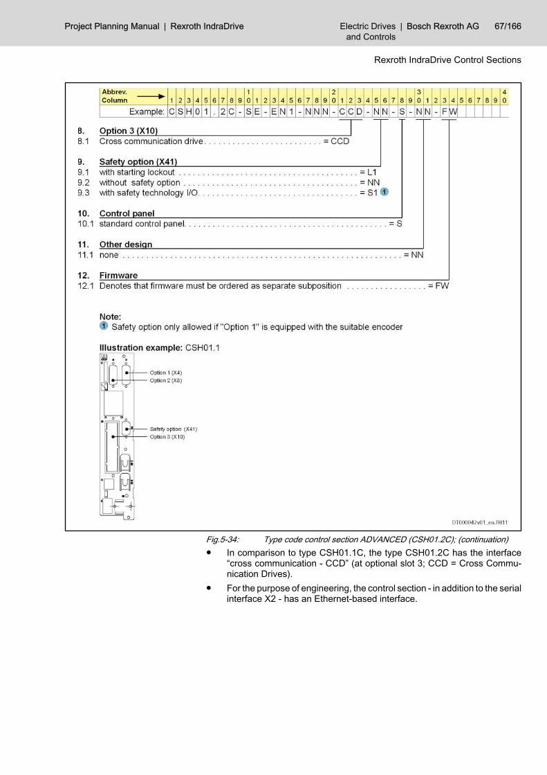
Fig.5-34: Type code control section ADVANCED (CSH01.2C); (continuation)● In comparison to type CSH01.1C, the type CSH01.2C has the interface
“cross communication - CCD” (at optional slot 3; CCD = Cross Commu‐nication Drives).
● For the purpose of engineering, the control section - in addition to the serialinterface X2 - has an Ethernet-based interface.
Project Planning Manual | Rexroth IndraDrive Electric Drivesand Controls
| Bosch Rexroth AG 67/166
Rexroth IndraDrive Control Sections

5.4.3 Dimensions ADVANCED
Fig.5-35: Dimensions ADVANCED
68/166 Bosch Rexroth AG | Electric Drivesand Controls
Rexroth IndraDrive | Project Planning Manual
Rexroth IndraDrive Control Sections

5.4.4 CSH01.1C - ADVANCED Front View with Connections
Front view Connectionpoint
Strandedwire
[mm²]
AWG Tighten‐ing tor‐
que[Nm]
Description
X7 memory card slot
option 1
option 2
X31; X32 0,08–1,5 28–14 - digital and analog in‐puts/outputs; voltage
input (24V, 0V)
option 3
option ST 1)
option MC 2)
X2 0,25–0,5 - - serial interface
H1 - - - interface for controlpanel
1) option ST = safety technology2) option MC = master communicationFig.5-36: Connections ADVANCED CSH01.1C
Functions
The specified factory settings apply to firmware MPx04.For additional notes on function and commissioning, see the fol‐lowing sections in the Functional Description of the firmware:● Analog Outputs● Analog Inputs● Digital Inputs/Outputs
Project Planning Manual | Rexroth IndraDrive Electric Drivesand Controls
| Bosch Rexroth AG 69/166
Rexroth IndraDrive Control Sections
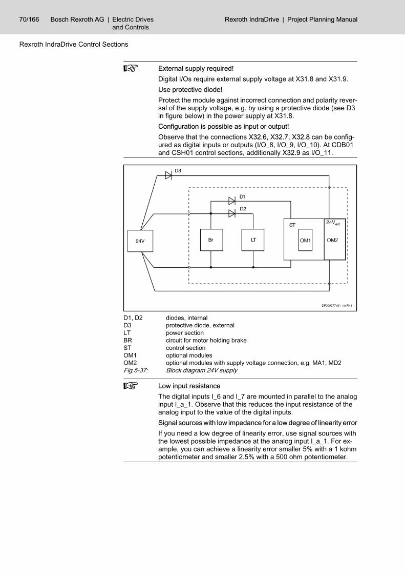
External supply required!Digital I/Os require external supply voltage at X31.8 and X31.9.Use protective diode!Protect the module against incorrect connection and polarity rever‐sal of the supply voltage, e.g. by using a protective diode (see D3in figure below) in the power supply at X31.8.Configuration is possible as input or output!Observe that the connections X32.6, X32.7, X32.8 can be config‐ured as digital inputs or outputs (I/O_8, I/O_9, I/O_10). At CDB01and CSH01 control sections, additionally X32.9 as I/O_11.
D1, D2 diodes, internalD3 protective diode, externalLT power sectionBR circuit for motor holding brakeST control sectionOM1 optional modulesOM2 optional modules with supply voltage connection, e.g. MA1, MD2Fig.5-37: Block diagram 24V supply
Low input resistanceThe digital inputs I_6 and I_7 are mounted in parallel to the analoginput I_a_1. Observe that this reduces the input resistance of theanalog input to the value of the digital inputs.Signal sources with low impedance for a low degree of linearity errorIf you need a low degree of linearity error, use signal sources withthe lowest possible impedance at the analog input I_a_1. For ex‐ample, you can achieve a linearity error smaller 5% with a 1 kohmpotentiometer and smaller 2.5% with a 500 ohm potentiometer.
70/166 Bosch Rexroth AG | Electric Drivesand Controls
Rexroth IndraDrive | Project Planning Manual
Rexroth IndraDrive Control Sections

Function Con‐nection
Factory setting Nominal data Figure;technical data
power consumption from 24V supply;connection at power section X13 or +24V/0V
- - see section “Power Consumption”
relay contact Rel 1 X31.1 ready for operationP‑0‑0115
DC 24 V1 A
X31 I X32
data see chapter7.1 Relay Contacts ,
page 139
Rel 1 X31.2
Project Planning Manual | Rexroth IndraDrive Electric Drivesand Controls
| Bosch Rexroth AG 71/166
Rexroth IndraDrive Control Sections

Function Con‐nection
Factory setting Nominal data Figure;technical data
digitalinputs
I_1type 2(probe)
X31.3 probe 1S‑0‑0401
can be con‐figured as
probe;24 V3 mA
typ. 1 µs
X31 I X32
data see chapter7.2 Digital Inputs/Out‐
puts, page 140
I_2type 2(probe)
X31.4 probe 2S‑0‑0402
I_3 X31.5 travel range limitswitch
P‑0‑0222
24 V3 mA
I_4 X31.6 travel range limitswitch
P‑0‑0222
I_5 X31.7 home switchS‑0‑0400
I_6 X32.4 can also be used asanalog input; see
I_a_1+
I_7 X32.5 can also be used asanalog input; see
I_a_1-
I/O_8 X32.6 E-StopP‑0‑0223
I/O_9 X32.7 combined I/O con‐figured as input I/
O_9; see alsoP‑0‑0302
I/O_10 X32.8 combined I/O con‐figured as input I/O_10; see also
P‑0‑0302
I/O_11 X32.9 combined I/O con‐figured as input I/O_11; see also
P‑0‑0302
72/166 Bosch Rexroth AG | Electric Drivesand Controls
Rexroth IndraDrive | Project Planning Manual
Rexroth IndraDrive Control Sections

Function Con‐nection
Factory setting Nominal data Figure;technical data
digitaloutputs
I/O_8 X32.6 combined I/O con‐figured as input I/
O_8; see alsoP‑0‑0302
24 V0.5 A
X31 I X32
data see chapter7.2.3 Digital Outputs ,
page 143
I/O_9 X32.7 combined I/O con‐figured as input I/
O_9; see alsoP‑0‑0302
I/O_10 X32.8 combined I/O con‐figured as input I/O_10; see also
P‑0‑0302
I/O_11 X32.9 combined I/O con‐figured as input I/O_11; see also
P‑0‑0302
analoginputs
voltage input I_a_1+ X32.4 can also be used asdigital input I_6
±10 Vtyp. 2 kohm
X31 I X32
data see chapter Ana‐log Input Type 4 , page
147example of connectionsee chapter 7-16Shieldconnection X32, page
144
I_a_1- X32.5 can also be used asdigital input I_7
analogoutputs
voltage output O_a_1 X32.1 5 V1 mA
X31 I X32
data see chapter Ana‐log Output Type 2 ,
page 148example of connectionsee chapter 7-16Shieldconnection X32, page
144
O_a_2 X32.2
reference potentialfor analog voltage
output
connection for signalshields
GND_a X32.3
Project Planning Manual | Rexroth IndraDrive Electric Drivesand Controls
| Bosch Rexroth AG 73/166
Rexroth IndraDrive Control Sections

Function Con‐nection
Factory setting Nominal data Figure;technical data
power supply ofdigital inputs/out‐
puts
power supply of digi‐tal inputs/outputs
+24V X31.8 X31 I X32
DC 19…30 V; max.1.1 A
see note on “protectivediode”
0V X31.9
serial interface RS232 X2
data see chapter7.4 X2, Serial Interface
(RS232) , page 149
optional func‐tions
allowed options: seeconfiguration table
see corresponding op‐tional module
Fig.5-38: Functions ADVANCED CSH01.1C
74/166 Bosch Rexroth AG | Electric Drivesand Controls
Rexroth IndraDrive | Project Planning Manual
Rexroth IndraDrive Control Sections

Optional Slots CSH01.1C
option MC Master communicationoption ST safety technologyFig.5-39: Options for ADVANCED CSH01.1C
The following configuration table shows which optional module issupported on which optional slot.Our sales representative will inform you on whether a certain com‐bination is allowed or not.
Optional mod‐ule Optional slot
option MC option 1 option 2 option 3 option ST(X41)
memory cardslot (X7)
control panel(H1)
SE ■ - - - - - -
PB ■ - - - - - -
Project Planning Manual | Rexroth IndraDrive Electric Drivesand Controls
| Bosch Rexroth AG 75/166
Rexroth IndraDrive Control Sections

Optional mod‐ule Optional slot
PL ■ - - - - - -
CO ■ - - - - - -
ET ■ - - - - - -
S3 ■ - - - - - -
CCD - - - ■ - - -
ENS - ■ ■ ■ - - -
EN1 - ■ ■ ■ - - -
EN2 - ■ ■ ■ - - -
MEM - ■ ■ ■ - - -
MA1 - - ■ ■ - - -
MD1 - - - ■ - - -
MD2 - - - ■ - - -
L1 - - - - ■ - -
S1 - - - - ■ - -
S - - - - - - ■
PFM02 - - - - - ■ -
■ allowed optional module on optional slot- not allowedFig.5-40: Configuration table CSH01.1C
5.4.5 CSH01.2C - ADVANCED General Information
The following documentation of ADVANCED CSH01.2C is preliminary.
76/166 Bosch Rexroth AG | Electric Drivesand Controls
Rexroth IndraDrive | Project Planning Manual
Rexroth IndraDrive Control Sections

Front View with Connections Front view Connection
pointStranded
wire[mm²]
AWG Tighten‐ing tor‐
que[Nm]
Description
X7 memory card slot
option 1
option 2
X31; X32 0,08–1,5 28–14 - digital and analog in‐puts/outputs; voltage
input (24V, 0V)
X24; X25 - - - cross communication -CCD
X26 - - - engineering interface
option ST 1)
option MC 2)
X2 0,25–0,5 - - serial interface
H1 - - - interface for controlpanel
1) option ST = safety technology2) option MC = master communicationFig.5-41: Connections ADVANCED CSH01.2
Functions
The specified factory settings apply to firmware MPx04.For additional notes on function and commissioning, see the fol‐lowing sections in the Functional Description of the firmware:● Analog Outputs● Analog Inputs● Digital Inputs/Outputs
Project Planning Manual | Rexroth IndraDrive Electric Drivesand Controls
| Bosch Rexroth AG 77/166
Rexroth IndraDrive Control Sections

External supply required!Digital I/Os require external supply voltage at X31.8 and X31.9.Use protective diode!Protect the module against incorrect connection and polarity rever‐sal of the supply voltage, e.g. by using a protective diode (see D3in figure below) in the power supply at X31.8.Configuration is possible as input or output!Observe that the connections X32.6, X32.7, X32.8 can be config‐ured as digital inputs or outputs (I/O_8, I/O_9, I/O_10). At CDB01and CSH01 control sections, additionally X32.9 as I/O_11.
D1, D2 diodes, internalD3 protective diode, externalLT power sectionBR circuit for motor holding brakeST control sectionOM1 optional modulesOM2 optional modules with supply voltage connection, e.g. MA1, MD2Fig.5-42: Block diagram 24V supply
Low input resistanceThe digital inputs I_6 and I_7 are mounted in parallel to the analoginput I_a_1. Observe that this reduces the input resistance of theanalog input to the value of the digital inputs.Signal sources with low impedance for a low degree of linearity errorIf you need a low degree of linearity error, use signal sources withthe lowest possible impedance at the analog input I_a_1. For ex‐ample, you can achieve a linearity error smaller 5% with a 1 kohmpotentiometer and smaller 2.5% with a 500 ohm potentiometer.
78/166 Bosch Rexroth AG | Electric Drivesand Controls
Rexroth IndraDrive | Project Planning Manual
Rexroth IndraDrive Control Sections

Function Con‐nection
Factory setting Nominal data Figure;technical data
power consumption from 24V supply;connection at power section X13 or +24V/0V
- - see section “Power Consumption”
relay contact Rel 1 X31.1 ready for operationP‑0‑0115
DC24 V1 A
X31 I X32
data see chapter7.1 Relay Contacts ,
page 139
Rel 1 X31.2
Project Planning Manual | Rexroth IndraDrive Electric Drivesand Controls
| Bosch Rexroth AG 79/166
Rexroth IndraDrive Control Sections

Function Con‐nection
Factory setting Nominal data Figure;technical data
digitalinputs
I_1type 2(probe)
X31.3 probe 1S‑0‑0401
can be con‐figured as
probe24 V3 mA
typ. 1 µs
X31 I X32
data see chapter7.2 Digital Inputs/Out‐
puts, page 140
I_2type 2(probe)
X31.4 probe 2S‑0‑0402
I_3 X31.5 travel range limitswitch
P‑0‑0222
24 V3 mA
I_4 X31.6 travel range limitswitch
P‑0‑0222
I_5 X31.7 home switchS‑0‑0400
I_6 X32.4 can also be used asanalog input; see
I_a_1+
I_7 X32.5 can also be used asanalog input; see
I_a_1-
I/O_8 X32.6 E-StopP-0-0223
I/O_9 X32.7 combined I/O con‐figured as input I/
O_9; see alsoP‑0‑0302
I/O_10 X32.8 combined I/O con‐figured as input I/O_10; see also
P‑0‑0302
I/O_11 X32.9 combined I/O con‐figured as input I/O_11; see also
P‑0‑0302
80/166 Bosch Rexroth AG | Electric Drivesand Controls
Rexroth IndraDrive | Project Planning Manual
Rexroth IndraDrive Control Sections

Function Con‐nection
Factory setting Nominal data Figure;technical data
digitaloutputs
I/O_8 X32.6 combined I/O con‐figured as input I/
O_8; see alsoP‑0‑0302
24 V0.5 A
X31 I X32
data see chapter7.2.3 Digital Outputs ,
page 143
I/O_9 X32.7 combined I/O con‐figured as input I/
O_9; see alsoP‑0‑0302
I/O_10 X32.8 combined I/O con‐figured as input I/O_10; see also
P‑0‑0302
I/O_11 X32.9 combined I/O con‐figured as input I/O_11; see also
P‑0‑0302
analoginputs
voltage input I_a_1+ X32.4 can also be used asdigital input I_6
±10 Vtyp.
160 kohm
X31 I X32
data see chapter Ana‐log Input Type 4 , page
147example of connectionsee chapter 7-16Shieldconnection X32, page
144
I_a_1- X32.5 can also be used asdigital input I_7
Project Planning Manual | Rexroth IndraDrive Electric Drivesand Controls
| Bosch Rexroth AG 81/166
Rexroth IndraDrive Control Sections

Function Con‐nection
Factory setting Nominal data Figure;technical data
analogoutputs
voltage output O_a_1 X32.1 5 V1 mA
X31 I X32
data see chapter Ana‐log Output Type 2 ,
page 148example of connectionsee chapter 7-16Shieldconnection X32, page
144
O_a_2 X32.2
reference potentialfor analog voltage
outputconnection for signal
shields
GND_a X32.3
power supply ofdigital inputs/out‐
puts
power supply of digi‐tal inputs/outputs
+24V X31.8 DC 19…30 V; max.1.1 A
see note on “protectivediode”
0V X31.9
serial interface RS232 X2
data see chapter7.4 X2, Serial Interface
(RS232) , page 149
CCD X24
CCD X25
82/166 Bosch Rexroth AG | Electric Drivesand Controls
Rexroth IndraDrive | Project Planning Manual
Rexroth IndraDrive Control Sections
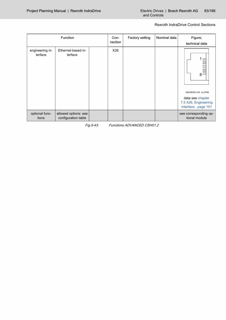
Function Con‐nection
Factory setting Nominal data Figure;technical data
engineering in‐terface
Ethernet-based in‐terface
X26
data see chapter7.5 X26, EngineeringInterface , page 151
optional func‐tions
allowed options: seeconfiguration table
see corresponding op‐tional module
Fig.5-43: Functions ADVANCED CSH01.2
Project Planning Manual | Rexroth IndraDrive Electric Drivesand Controls
| Bosch Rexroth AG 83/166
Rexroth IndraDrive Control Sections

Optional Slots CSH01.2C
option MC master communicationoption ST safety technologyFig.5-44: Options for ADVANCED CSH01.2C
The following configuration table shows which optional module issupported on which optional slot.Our sales representative will inform you on whether a certain com‐bination is allowed or not.
Optionalmodule Optional slot
option MC option 1 option 2 option 3 (onboard)
option ST(X41)
memory cardslot (X7)
control panel(H1)
SE ■ - - - - - -
PB ■ - - - - - -
84/166 Bosch Rexroth AG | Electric Drivesand Controls
Rexroth IndraDrive | Project Planning Manual
Rexroth IndraDrive Control Sections

Optionalmodule Optional slot
PL ■ - - - - - -
CO ■ - - - - - -
ET ■ - - - - - -
S3 ■ - - - - - -
CCD - - - ■ - - -
ENS - ■ ■ - - - -
EN1 - ■ ■ - - - -
EN2 - ■ ■ - - - -
MEM - ■ ■ - - - -
MA1 - - ■ - - - -
MD1 - - - - - - -
MD2 - - - - - - -
L1 - - - - ■ - -
S1 - - - - ■ - -
S - - - - - - ■
PFM02 - - - - - ■ -
■ allowed optional module on optional slot- not allowedFig.5-45: Configuration table CSH01.2C
Project Planning Manual | Rexroth IndraDrive Electric Drivesand Controls
| Bosch Rexroth AG 85/166
Rexroth IndraDrive Control Sections

Bosch Rexroth AG | Electric Drivesand Controls
Rexroth IndraDrive | Project Planning Manual

6 Optional Modules for Control Sections6.1 OverviewOptional module Function Name of op‐
tional moduleConnection
point
Notes
master communica‐tions
master communication viaSERCOS interface
SE (HCC02)X20; X21
master communication based on fiber optic cables
master communication viaPROFIBUS
PB (HCC03)X30
field bus PROFIBUS
master communication viaDeviceNet
CO (HCC06)X60
field bus DeviceNet; connection via screw terminal
master communication viaDeviceNet
CDX61
field bus DeviceNet; connection via D‑SUB interface(in preparation)
master communication via par‐allel interface
PL (HCC01)X15
parallel interface
master communication viaCANopen
CO (HCC06)X60
field bus CANopen; connection via screw terminal
master communication viaCANopen
CDX61
field bus CANopen; connection via D‑SUB interface(in preparation)
master communication viaPROFINET IO
ET (HCC08) field bus PROFINET
master communication viaSERCOS III
S3 (HCC07)X22, X23
master communication based on Ethernet
communication cross communication viaSERCOS III
CCD(HMC01)X24, X25
communication between drive controllers based onEthernet
encoder evaluations for encoder systems ofIndraDyn motors
ENS (HFI03) standard for motors of IndraDyn product range ; (en‐coder systems S1, M1, S2 and M2)12 V power supply
for resolvers and encoder sys‐tems with HSF interface
EN1 (HFI01) standard for MKD, MKE and MHD motors (encodersystems R0, R1, S0 and M0)8 V power supply
for encoder systems with 5 Vsupply (Sense function re‐quired)
EN2 (HFI02) 5 V power supply (encoder systems C0)
emulation of absolute and in‐cremental encoders
MEM(HFE01)
emulation absolute encoder in SSI format
Project Planning Manual | Rexroth IndraDrive Electric Drivesand Controls
| Bosch Rexroth AG 87/166
Optional Modules for Control Sections

Optional module Function Name of op‐tional moduleConnection
point
Notes
I/O extensions extension “analog inputs/out‐puts”
MA1(HAS01)
2 analog differential input channels2 analog output channels
extension “digital inputs/out‐puts”
MD1(HEA01)
12 digital inputs8 digital outputs
extension “digital inputs/out‐puts”
MD2(HEA02)X17, X16
16 digital inputs in 2 groups16 digital outputs in 4 groupsSSI encoder evaluation
safety technology I/O for safety technology S1 (HSI11)X41
starting lockout L1 (HSI01)X41
control panels standard control panel S single-line display
comfort control panel C multiline display
memory exchangeable medium for pa‐rameters and firmware
PFM02.1X7
MultiMediaCard (MMC)
Fig.6-1: Available optional modules
6.2 Master Communication 6.2.1 SE - SERCOS
CAUTION
Risk of damage!The maximum tightening torque of the union nut at the coupling elements ofthe fiber optic cable is 0.6 Nm.
Description
Fig.6-2: SERCOS interfaceLED H20 Distortion LED of SERCOS interface
Pin Assignment X20 TX
X21 RX
Fig.6-3: Pin assignment
88/166 Bosch Rexroth AG | Electric Drivesand Controls
Rexroth IndraDrive | Project Planning Manual
Optional Modules for Control Sections

Fig.6-4: Pin assignmentData Rate, Transmission Power The data rate and transmission power can be set via the serial interface X2 or
with the control panel.Fiber optic cables:Drive controllers with a SERCOS interface are connected to higher-level controlunits by means of fiber optic cables.The fiber optic cables (cables, connectors or ready-made cables) have to beordered separately.For more detailed information on the subject of “fiber optic cables”, see appli‐cation manual “Rexroth Connection System, fiber optic cables” (DOK-CON‐NEC-CABLE*LWL**-AWxx-EN-P, part. no. R911284755). This applicationdescription contains the following points:● Fiber optic cable - general information● Basic planning information for optical transmission systems● Routing guidelines for fiber optic cables● Attenuation measurements of the standard plastic fiber optic cables● FSMA selection list for plug-in connectors and fiber optic cables● Assembly guidelines for FSMA connectors● Tools for assembly of fiber optic cables
6.2.2 PB - PROFIBUS Description
Fig.6-5: PROFIBUS interface
Project Planning Manual | Rexroth IndraDrive Electric Drivesand Controls
| Bosch Rexroth AG 89/166
Optional Modules for Control Sections

Connectionpoint Type No. of
polesType of de‐
signStranded wire
[mm²]Figure
X30 D-Sub 9 female (de‐vice) 0,08–0,5
Fig.6-6: ConnectionsPin Assignment Pin DIR Signal Function
1 - n. c.
2 - n. c.
3 I/O RS485+ receive/transmit data-positive
4 O CNTR-P repeater control signal
5 0 V 0 V
6 O +5 V repeater supply
7 - n. c.
8 I/O RS485- receive/transmit data-negative
9 0V 0 V
Fig.6-7: Signal assignmentShield Connection Via D-sub fastening screws and metallized connector housing.
Compatibility of the Interface According to DIN EN 50 170Recommended Cable Type According to DIN EN 50 170 - 2, cable type A
Signal Specification Signal Specification
+5Vrepeater supply
+5 V (±10%)max. 75 mA
repeater control signal
TTL-compatible:● 1: transmit● 0: receiveoutput resistance: 350RVOL ≤ 0.8 V at IOL ≤ 2 mA
VOH ≥ 3.5 V at IOH ≤ 1 mA
receive/transmit data EIA-RS485 standard
Fig.6-8: Signal specification
CAUTION
Danger of destroying output “+5V repeater supply” by overload!Do not short-circuit the output.Do not exceed the maximum current.
90/166 Bosch Rexroth AG | Electric Drivesand Controls
Rexroth IndraDrive | Project Planning Manual
Optional Modules for Control Sections

Diagnostic Displays For the significance of the diagnostic displays, see Functional Description ofthe respective firmware.
Bus Connectors The PROFIBUS connectors each have a connectable terminating resistor. Theterminating resistor must always be active at both the first and last bus node.Carry out the connection as shown in the figures below.
1) shield2) bus connection and switch position for first node and last node3) bus connection and switch position for all other nodesFig.6-9: Preparing a cable for connecting a bus connectorTo assemble the bus cable, proceed as follows:● use cable according to DIN EN50170 / 2 edition 1996● strip cable (see figure above)● insert both cores into screw terminal block
Do not interchange the cores for A and B.
● press cable sheath between both clamps● screw on both cores in screw terminals
1) switch position for first slave and last slave in PROFIBUS-DP2) cable shield must have direct contact to metalFig.6-10: Bus connection for first slave and last slave, bus connector with 9-pin
D-Sub female connector, INS0541
Project Planning Manual | Rexroth IndraDrive Electric Drivesand Controls
| Bosch Rexroth AG 91/166
Optional Modules for Control Sections

1) terminating resistor is off2) cable shield must have direct contact to metalFig.6-11: Bus connection for all other slaves, bus connector with 9-pin D-Sub fe‐
male connector, INS0541
1) switch position for first slave and last slave in PROFIBUS-DP2) cable shield must have direct contact to metalFig.6-12: Bus connection for first slave and last slave, without 9-pin D-Sub female
connector, INS0540
1) terminating resistor is off2) cable shield must have direct contact to metalFig.6-13: Bus connection for all other slaves, without 9-pin D-Sub female con‐
nector, INS0540Connect the drive controller to a control unit using a shielded two-wire line inaccordance with DIN 19245/Part 1.
92/166 Bosch Rexroth AG | Electric Drivesand Controls
Rexroth IndraDrive | Project Planning Manual
Optional Modules for Control Sections

6.2.3 PL - Parallel Interface X15, Parallel Interface - PL
DescriptionConnec‐tion point Type No. of
polesType of de‐
signSolid wire
[mm²]
Strandedwire
[mm²]Figure
X15 D-Sub 37 pins on de‐vice - 0,08–0,5
Fig.6-14: ConnectionsPin Assignment
FunctionCon‐nec‐tion
Factory setting Technical data
digital inputgroup 0
I_0.0 1P-0-4026, Posi‐tioning blockselection; bit 0
see chapter DigitalInputs Type 1(Standard) , page140
I_0.1 20P-0-4026, Posi‐tioning blockselection; bit 1
I_0.2 2P-0-4026, Posi‐tioning blockselection; bit 2
I_0.3 21P-0-4026, Posi‐tioning blockselection; bit 3
digital outputgroup 0
O_0.0 28 P-0-0115, bit 1;ready signal
see chapter DigitalOutputs , page 143
O_0.1 10S-0-0059, Posi‐tion switch flagparameter; bit 0
O_0.2 29
S-0-0403, Posi‐tion feedbackvalue status;bit 0
O_0.3 11S-0-0331, Sta‐tus 'n_feedback= 0'
Project Planning Manual | Rexroth IndraDrive Electric Drivesand Controls
| Bosch Rexroth AG 93/166
Optional Modules for Control Sections

FunctionCon‐nec‐tion
Factory setting Technical data
power supplyfor input/output
group 0+24V 30
DC 19 … 30 Vmax. 1.2 A
digital inputgroup 1
I_1.0 3P-0-4026, Posi‐tioning blockselection; bit 4
see chapter DigitalInputs Type 1(Standard) , page140
I_1.1 22P-0-4026, Posi‐tioning blockselection; bit 5
I_1.2 4
P-0-4060, Posi‐tioning blockcontrol word;bit 0
I_1.3 23
S-0-0148,C0600 Drive-controlled hom‐ing procedurecommand; bit 0
digital outputgroup 1
O_1.0 12P-0-4061; bit 4,end positionreached
see chapter DigitalOutputs 143
O_1.1 31 P-0-0115; bit 2,warning
O_1.2 13S-0-0437;bit 12, jog modeactive
O_1.3 32S-0-0437; bit 3,interpolator hal‐ted
power supplyfor input/output
group 1+24V 14
DC 19 … 30 Vmax. 1.2 A
digital inputgroup 2
I_2.0 5S-0-0346, Posi‐tioning controlword; bit 1
see chapter DigitalInputs Type 1(Standard) , page140
I_2.1 24S-0-0346, Posi‐tioning controlword; bit 2
I_2.2 6
P-0-4028, De‐vice controlword; Drive ON;bit 15
I_2.3 25
P-0-4028, De‐vice controlword; DriveHALT; bit 13
94/166 Bosch Rexroth AG | Electric Drivesand Controls
Rexroth IndraDrive | Project Planning Manual
Optional Modules for Control Sections

FunctionCon‐nec‐tion
Factory setting Technical data
digital outputgroup 2
O_2.0 33
P-0-4051, Posi‐tioning blockacknowledg‐ment; bit 0
see chapter DigitalOutputs , page 143
O_2.1 15
P-0-4051, Posi‐tioning blockacknowledg‐ment; bit 1
O_2.2 34
P-0-4051, Posi‐tioning blockacknowledg‐ment; bit 2
O_2.3 16
P-0-4051, Posi‐tioning blockacknowledg‐ment; bit 3
power supplyfor input/output
group 2+24V 35
DC 19 … 30 Vmax. 1.2 A
digital inputgroup 3
I_3.0 7
S-0-0099,C0500 Resetclass 1 diag‐nostics
see chapter DigitalInputs Type 1(Standard) , page140
I_3.1 26
I_3.2 8
I_3.3 27
digital outputgroup 3
O_3.0 17
P-0-4051, Posi‐tioning blockacknowledg‐ment; bit 4
see chapter DigitalOutputs , page 143
O_3.1 36
P-0-4051, Posi‐tioning blockacknowledg‐ment; bit 5
O_3.2 18
P-0-4051, Posi‐tioning blockacknowledg‐ment; bit 6
O_3.3 37
P-0-4051, Posi‐tioning blockacknowledg‐ment; bit 7
power supplyfor input/output
group 3+24V 19
DC 19 … 30 Vmax. 1.2 A
Project Planning Manual | Rexroth IndraDrive Electric Drivesand Controls
| Bosch Rexroth AG 95/166
Optional Modules for Control Sections
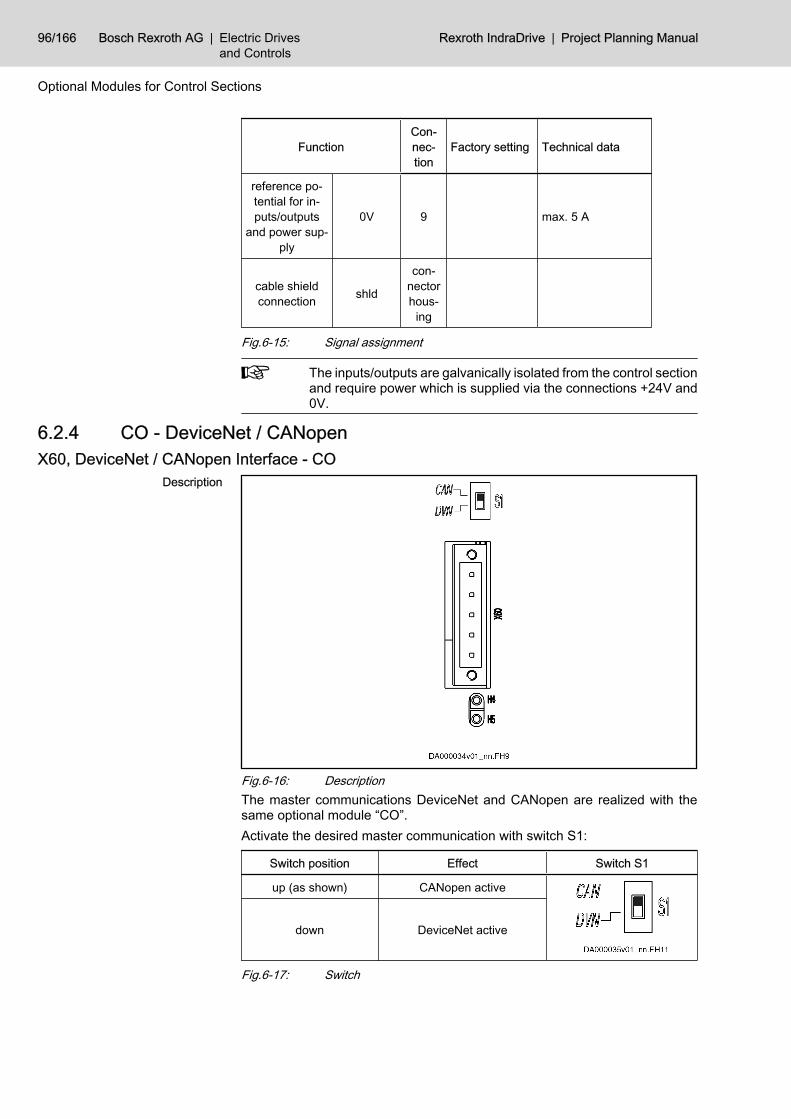
FunctionCon‐nec‐tion
Factory setting Technical data
reference po‐tential for in‐puts/outputs
and power sup‐ply
0V 9 max. 5 A
cable shieldconnection shld
con‐nectorhous‐
ing
Fig.6-15: Signal assignment
The inputs/outputs are galvanically isolated from the control sectionand require power which is supplied via the connections +24V and0V.
6.2.4 CO - DeviceNet / CANopen X60, DeviceNet / CANopen Interface - CO
Description
Fig.6-16: DescriptionThe master communications DeviceNet and CANopen are realized with thesame optional module “CO”.Activate the desired master communication with switch S1:
Switch position Effect Switch S1
up (as shown) CANopen active
down DeviceNet active
Fig.6-17: Switch
96/166 Bosch Rexroth AG | Electric Drivesand Controls
Rexroth IndraDrive | Project Planning Manual
Optional Modules for Control Sections

Properties of the ConnectorConnec‐tion point Type No. of
polesSolid wire
[mm²]
Strandedwire
[mm²]AWG Figure
X60
springterminalfemale
(connec‐tor)
5 0,25–2,5 0,25–1,5 24–16
Fig.6-18: Connections
CAUTION
Risk of damage!Maximum allowed tightening torque of locking screws: 0.5 Nm.
Display ElementsSignificance for CANopen LED Significance Color Description
H4 Run green signals operating states; for details seeFunctional Description
H5 Error red signals error states; for details see Func‐tional Description
Fig.6-19: Significance of display elements for CANopenSignificance for DeviceNet LED Significance Color Description
H4 module statusred malfunction on module; for details see
Functional Description
green module OK; for details see Functional De‐scription
H5 network statusred malfunction on network; for details see
Functional Description
green network OK; for details see Functional De‐scription
Fig.6-20: Significance of display elements for DeviceNetAssignment X60 Pin Signal Function
1 VP- 0 V potential 24 V supply voltage
2 CAN_L bidirectional data signal CAN_L
3 Drain/Shield shield connection
4 CAN_H bidirectional data signal CAN_H
5 VP+ 24 V supply voltage – plus
Fig.6-21: Signal assignment optional module CO
Project Planning Manual | Rexroth IndraDrive Electric Drivesand Controls
| Bosch Rexroth AG 97/166
Optional Modules for Control Sections

Main Features Feature DeviceNet CANopen
compatibility according to DIN EN50325-2 according to EN 50325-4
max. possible number ofnodes 64 nodes max. 127 nodes
bus topology line topology line topology
bus terminator (ISO 11898) 124 ohm each, 1%, 200 mW; connect at both bus endsto X60.2 and X60.4
transmission medium 2 twisted two-wire lines (4-pin) with shield
max. allowed bus (line)lengths depending on bit rate
recommended connectioncable our RKS number or third-party type
Fig.6-22: Main featuresAllowed Network Dimension (Bus
Lengths) Bit rate[kBaud]
Max. allowed network dimension[m]
DeviceNet CANopen
1000 - 25
800 - 50
500 40 100
250 250 250
125 500 500
50 - 1000
20 - 2500
10 - 5000
Fig.6-23: Network dimension
98/166 Bosch Rexroth AG | Electric Drivesand Controls
Rexroth IndraDrive | Project Planning Manual
Optional Modules for Control Sections

6.2.5 CD - DeviceNet / CANopen (Preliminary) X61, DeviceNet / CANopen Interface - CD
Description
Fig.6-24: DescriptionThe master communications DeviceNet and CANopen are realized with thesame optional module “CD”. In comparison to the optional module “CO” withterminal block, the optional module “CD” has a D-SUB connector for field busconnection.Activate the desired master communication with switch S1:
Switch position Effect Switch S1
up CANopen active
down DeviceNet active
Fig.6-25: SwitchProperties of the Connector Connec‐
tion point Type No. ofpoles
Type of de‐sign
Stranded wire[mm²]
Figure
X61 D-Sub 9 pins on de‐vice 0,25–0,5
Fig.6-26: Connection
Project Planning Manual | Rexroth IndraDrive Electric Drivesand Controls
| Bosch Rexroth AG 99/166
Optional Modules for Control Sections

Display ElementsSignificance for CANopen LED Significance Color Description
H4 Run green signals operating states; for details seeFunctional Description
H5 Error red signals error states; for details see Func‐tional Description
Fig.6-27: Significance of display elements for CANopenSignificance for DeviceNet LED Significance Color Description
H4 module statusred malfunction on module; for details see
Functional Description
green module OK; for details see Functional De‐scription
H5 network statusred malfunction on network; for details see
Functional Description
green network OK; for details see Functional De‐scription
Fig.6-28: Significance of display elements for DeviceNetAssignment X61 Pin Signal Function
1 VP- 0 V potential 24 V supply voltage
2 CAN_L bidirectional data signal CAN_L
3 Drain/Shield shield connection
4 CAN_H bidirectional data signal CAN_H
5 VP+ 24 V supply voltage – plus
6 n. c. -
7 n. c. -
8 n. c. -
9 n. c. -
Fig.6-29: Signal assignment optional module CD
100/166 Bosch Rexroth AG | Electric Drivesand Controls
Rexroth IndraDrive | Project Planning Manual
Optional Modules for Control Sections

Main Features Feature DeviceNet CANopen
compatibility according to DIN EN50325-2 according to EN 50325-4
max. possible number ofnodes 64 nodes 127 nodes
bus topology line topology line topology
bus terminator (ISO 11898) 124 ohm each, 1%, 200 mW; connect at both bus endsto X60.2 and X60.4
transmission medium 2 twisted two-wire lines (4-pin) with shield
max. allowed bus (line)lengths depending on bit rate
recommended connectioncable our RKS number or third-party type
Fig.6-30: Main featuresBus Lengths Depending on Bit
Rates Bit rate[kBaud]
Max. allowed network dimension[m]
DeviceNet CANopen
1000 - 25
800 - 50
500 40 100
250 250 250
125 500 500
50 - 1000
20 - 2500
10 - 5000
Fig.6-31: Network dimension
6.2.6 S3 - SERCOS III Description SERCOS III is the Ethernet-based version of SERCOS 2. The interface corre‐
sponds to standard IEE 802.3.
Project Planning Manual | Rexroth IndraDrive Electric Drivesand Controls
| Bosch Rexroth AG 101/166
Optional Modules for Control Sections

Fig.6-32: SERCOS III connection points
Connectionpoints Type No. of
poles Figure
X22, X23 RJ45 8
Fig.6-33: ConnectionsAssignment X22, X23 Pin Signal Function
1 TD+ 10/100 Base-T Transmit, Differential Output A
2 TD- 10/100 Base-T Transmit, Differential Output B
3 RD+ 10/100 Base-T Receive, Differential Input A
4 n. c. -
5 n. c. -
6 RD- 10/100 Base-T Receive, Differential Input B
7 n. c. -
8 n. c. -
housing shield connection
Fig.6-34: Signal assignmentCompatibility of the Interface 10 Base-T according to IEEE 802.3i
100 Base-T according to IEEE 802.3uRecommended Cable Type According to CAT 5
102/166 Bosch Rexroth AG | Electric Drivesand Controls
Rexroth IndraDrive | Project Planning Manual
Optional Modules for Control Sections

Display Elements LED Significance Color Description
H6, H8 Status yellow data transmission running
H7, H9 Link green connection to network available
H7, H9 - orange -
Fig.6-35: Significance of display elements
6.2.7 CCD - Cross Communication Description The interface corresponds to standard IEE 802.3.
Fig.6-36: SERCOS III connection points CCD
Connection points Type No. ofpoles Figure
X24, X25 RJ45 8
Fig.6-37: Connections
Project Planning Manual | Rexroth IndraDrive Electric Drivesand Controls
| Bosch Rexroth AG 103/166
Optional Modules for Control Sections

Assignment X24, X25 Pin Signal Function
1 TD+ 10/100 Base-T Transmit, Differential Output A
2 TD- 10/100 Base-T Transmit, Differential Output B
3 RD+ 10/100 Base-T Receive, Differential Input A
4 n. c. -
5 n. c. -
6 RD- 10/100 Base-T Receive, Differential Input B
7 n. c. -
8 n. c. -
housing shield connection
Fig.6-38: Signal assignmentCompatibility of the Interface 10 Base-T according to IEEE 802.3i
100 Base-T according to IEEE 802.3uRecommended Cable Type According to CAT 5
Display Elements LED Significance Color Description
H10, H12 Status yellow data transmission running
H11, H13 Link green connection to network available
H11, H13 - orange -
Fig.6-39: Significance of display elements
6.3 Encoder Evaluation6.3.1 ENS - Standard Encoder Evaluation Interface Standard Encoder Evaluation ENS
Description For encoders with a control voltage supply of 12 volt:● encoder system of IndraDyn S motors (MSK motors)● 1 Vpp with HIPERFACE®● 1 Vpp with EnDat 2.1● 1 Vpp with reference track● 5V-TTL square-wave encoder with reference
Connec‐tion point Type No. of
polesType of de‐
signStranded wire
[mm²]Figure
X8 D-Sub 15 female (de‐vice) 0,25–0,5
Fig.6-40: Connection
104/166 Bosch Rexroth AG | Electric Drivesand Controls
Rexroth IndraDrive | Project Planning Manual
Optional Modules for Control Sections

Pin Assignment Connection Signal Function
1 GND_shld connection for signal shields
2 A+ track A positive
3 A- track A negative
4 GND_Encoder power supply reference potential
5 B+ track B positive
6 B- track B negative
7 EncData+ data transmission positive
8 EncData- data transmission negative
9 R+ reference track positive
10 R- reference track negative
11 VCC_Encoder power supply
12 n. c.
13 EncCLK+ clock positive
14 EncCLK- clock negative
15 n. c.
Fig.6-41: Pin assignment
Properties of ENSVoltage for Encoder Supply
VCC_Encoder Data Unit Min. Typ. Max.
voltage for encoder supplyVCC_Encoder V 11,15 11,6 12,3
output current mA 500
Fig.6-42: Encoder supply ENSInput Circuit for Sine Signals A+, A-
or B+, B- or R+, R-
Fig.6-43: Input circuit for sine signals (block diagram)Properties of Differential Input Data Unit Min. Typ. Max.
amplitude encoder signal(USSencodersignal)
V 0,8 1,0 1,0 + 0,2
input resistance ohm 120
converter width A/D converter bit 12
limit frequency (-3 dB) kHz 500
input frequency for 5V-TTL sig‐nals (square-wave) kHz 400
amplitude 5V-TTL signals V 5,25
Fig.6-44: Differential input
Project Planning Manual | Rexroth IndraDrive Electric Drivesand Controls
| Bosch Rexroth AG 105/166
Optional Modules for Control Sections

The allowed input frequency for 5 V-TTL signals is lower than thelimit frequency, because the differential input is overridden with ap‐plied 5 V signals.
Signal Assignment to the Actual Position Value
Signal assignment 1) Signal designation Signal shape Actual position value (with de‐fault setting)
sine (1 Vpp) without ab‐solute value
increasing
sine (1 Vpp) with absolutevalue
increasing
1) see following noteFig.6-45: Signal assignment to the actual position value
The encoder signal assignment to the inputs is based on clockwiserotation (front view to motor shaft).● Track A (A+, A-, “cos”) advances track B (B+, B-, “sin”) 90°
electrically.● The actual position value increases in this case (unless neg‐
ation takes effect).● If available, the reference track R (R+, R-) provides the refer‐
ence mark pulse at positive signals of track A and track B (inthe so-called “0-th” quadrant).
Standard setting: see Functional Description of firmware
106/166 Bosch Rexroth AG | Electric Drivesand Controls
Rexroth IndraDrive | Project Planning Manual
Optional Modules for Control Sections
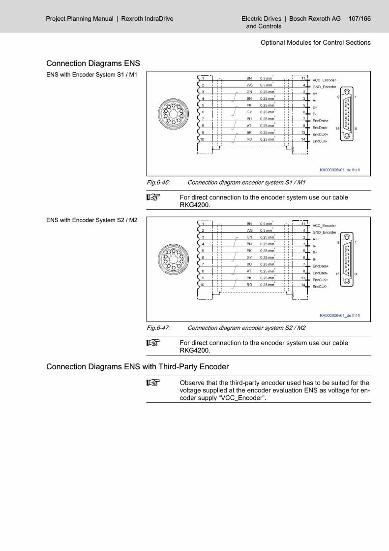
Connection Diagrams ENSENS with Encoder System S1 / M1
Fig.6-46: Connection diagram encoder system S1 / M1
For direct connection to the encoder system use our cableRKG4200.
ENS with Encoder System S2 / M2
Fig.6-47: Connection diagram encoder system S2 / M2
For direct connection to the encoder system use our cableRKG4200.
Connection Diagrams ENS with Third-Party Encoder
Observe that the third-party encoder used has to be suited for thevoltage supplied at the encoder evaluation ENS as voltage for en‐coder supply “VCC_Encoder”.
Project Planning Manual | Rexroth IndraDrive Electric Drivesand Controls
| Bosch Rexroth AG 107/166
Optional Modules for Control Sections

ENS with Third-Party EncoderHIPERFACE®
Fig.6-48: Connection diagram third-party encoder HIPERFACE®ENS with Third-Party Encoder En‐
Dat 2.1
Fig.6-49: Connection diagram third-party encoder EnDat 2.1ENS with Third-Party Encoder
1Vpp
Fig.6-50: Connection diagram third-party encoder 1Vpp
108/166 Bosch Rexroth AG | Electric Drivesand Controls
Rexroth IndraDrive | Project Planning Manual
Optional Modules for Control Sections

ENS with Third-Party Encoder 5V-TTL
Fig.6-51: Connection diagram third-party encoder 5V-TTL
Allowed Encoder Cable Lengths at ENSThe current consumption of the connected encoder system generates a voltagedrop due to the ohmic resistance of the encoder cable (line cross section andline length). This reduces the signal at the encoder input.
I [mA] current consumptionl [m] cable length0,5; 1,0; 1,5 cable cross sections in mm2Fig.6-52: Allowed encoder cable length
Example For an encoder cable with a length of 75 m and a cross section of 0.5 mm2,encoder systems with a current consumption of a maximum of 175 mA areallowed. If current consumption is higher, this requires an encoder cable witha cross section greater than 0.5 mm2.
6.3.2 EN1 - Resolver and HSF Encoder Evaluation Interface Resolver and HSF Encoder Evaluation EN1
Description For encoder systems with a control voltage supply of DC8 volt or AC18.2 voltpeak-peak:
Project Planning Manual | Rexroth IndraDrive Electric Drivesand Controls
| Bosch Rexroth AG 109/166
Optional Modules for Control Sections

● digital servo feedback from Rexroth (encoder interface HSF for MHD mo‐tors)
● resolver (encoder interface for MKD motors)● resolver without data memory● Hall sensor box SHL01.1 (for position detection of the primary part of
IndraDyn L and LSF motors)
Connec‐tion point Type No. of
polesType of de‐
signStranded wire
[mm²]Figure
- D-Sub 15 female (de‐vice) 0,25–0,5
Fig.6-53: ConnectionPin Assignment Connection Signal Function
1 GND_shld connection for signal shields
2 A+ track A positive
3 B+ track B positive
4 GND_Encoder power supply reference potential
5 n. c. n. c.
6 n. c. n. c.
7 I2C_SCLK clock line for I²C interface
8 I2C_SDAout data transmission to encoder
9 A- track A negative
10 B- track B negative
11 n. c. n. c.
12 VCC_Encoder power supply
13 n. c. n. c.
14 I2C_Fsample data request
15 I2C_SDAin data transmission from encoder
Fig.6-54: Pin assignment
Properties EN1Encoder Supply Resolver Data Unit Min. Typ. Max.
AC output voltage VVC_Encoder(peak-peak value) V 18,2 1)
output frequency sine kHz 4
110/166 Bosch Rexroth AG | Electric Drivesand Controls
Rexroth IndraDrive | Project Planning Manual
Optional Modules for Control Sections

Data Unit Min. Typ. Max.
output current mA 70
d.c. resistance of load ohm 35 1) DC8V are applied in the switch-on phase.Fig.6-55: Encoder supply resolver
Encoder Supply Digital ServoFeedback Data Unit Min. Typ. Max.
DC output voltage VVC_Encoder V 7,8 8 8,2
output current mA 250
Fig.6-56: Encoder supply HSFInput Circuit A+, A- or B+, B-
R1 5kR2 5kR3 20k (HSF) or 2k5 (resolver)R4 20k (HSF) or 2k5 (resolver)C1 not specifiedC2 not specifiedFig.6-57: Input circuit (block diagram)
Differential Input for HSF Operation Data Unit Min. Typ. Max.
amplitude encoder signal sine V 0,8 1,0 1,1
input resistance kohm 9,5 10 10,5
converter width A/D converter bit 12
limit frequency (-3 dB) kHz 100
Fig.6-58: Input data HSFDifferential Input for Resolver Op‐
eration Data Unit Min. Typ. Max.
allowed amplitude of encoder signalsine V 9,0
input resistance kohm 9,5 10 10,5
converter width A/D converter bit 12
limit frequency (-3 dB) kHz 18
Fig.6-59: Input data resolver operation
Project Planning Manual | Rexroth IndraDrive Electric Drivesand Controls
| Bosch Rexroth AG 111/166
Optional Modules for Control Sections

Signal Assignment to the Actual Position Value
Signal assignment Signal designation Signal shape Actual position value (with de‐fault setting)
HSF (sine 1 Vpp without120 ohm terminating re‐
sistor, I2C bus)increasing
amplitude-modulated signal
resolver increasing
Fig.6-60: Signal assignment to the actual position value
Connection Diagrams EN1EN1 with Encoder System R0 and
R1
Fig.6-61: Connection diagram
For direct connection to the encoder system use our cableIKS4043.
112/166 Bosch Rexroth AG | Electric Drivesand Controls
Rexroth IndraDrive | Project Planning Manual
Optional Modules for Control Sections

EN1 with Encoder System S0 andM0
Fig.6-62: Connection diagram
For direct connection to the encoder system use our cableIKS4042.
EN1 with Hall Sensor Box SHL01
Fig.6-63: Connection diagram
For direct connection to the encoder system use our cableIKS4042.
6.3.3 EN2 - Encoder Evaluation Interface Encoder Evaluation EN2
Description For encoders with a control voltage supply of 5 volt:● EnDat2.1 with Sense lines● sine encoder (1 Vpp) with reference track● square-wave encoder (TTL) with reference track
Connec‐tion point Type No. of
polesType of de‐
signStranded wire
[mm²]Figure
- D-Sub 15 pins on de‐vice 0,25–1,0
Fig.6-64: Connection
Project Planning Manual | Rexroth IndraDrive Electric Drivesand Controls
| Bosch Rexroth AG 113/166
Optional Modules for Control Sections

Pin Assignment Connection Signal Function
1 Sense+ return of supply voltage
2 Sense- return of supply voltage
3 R- reference track negative
4 R+ reference track positive
5 B- track B negative
6 B+ track B positive
7 A+ track A positive
8 A- track A negative
9 EncData+ data transmission
10 GND_Encoder power supply reference potential
11 EncCLK+ clock positive
12 VCC_Encoder power supply
13 EncCLK- clock negative
14 GND_shld connection for signal shields
15 EncData- data transmission
Fig.6-65: Pin assignment
Properties EN2VCC_Encoder (Encoder Supply) Data Unit Min. Typ. Max.
DC output voltage VCC_Encoderwith voltage return (Sense) V 4,75 5,0 5,25
DC output voltage VCC_Encoderwithout voltage return (Sense) V 4,85 5,1 5,35
output current mA 350
d.c. resistance of load ohm 35
Fig.6-66: Encoder supply EN2Input Circuit for Sine Signals A+, A-
or B+, B- or R+, R-
Fig.6-67: Input circuit for sine signals (block diagram)Properties of Differential Input for
Sine Signals Data Unit Min. Typ. Max.
allowed amplitude of encoder signalpeak-peak (UPPencodersignal)
V 0,8 1,0 1,2
limit frequency (-3 dB) kHz 500
converter width A/D converter bit 12
input resistance ohm 120
Fig.6-68: Differential input sine
114/166 Bosch Rexroth AG | Electric Drivesand Controls
Rexroth IndraDrive | Project Planning Manual
Optional Modules for Control Sections
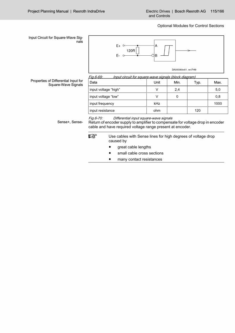
Input Circuit for Square-Wave Sig‐nals
Fig.6-69: Input circuit for square-wave signals (block diagram)Properties of Differential Input for
Square-Wave Signals Data Unit Min. Typ. Max.
input voltage “high” V 2,4 5,0
input voltage “low” V 0 0,8
input frequency kHz 1000
input resistance ohm 120
Fig.6-70: Differential input square-wave signalsSense+, Sense- Return of encoder supply to amplifier to compensate for voltage drop in encoder
cable and have required voltage range present at encoder.
Use cables with Sense lines for high degrees of voltage dropcaused by● great cable lengths● small cable cross sections● many contact resistances
Project Planning Manual | Rexroth IndraDrive Electric Drivesand Controls
| Bosch Rexroth AG 115/166
Optional Modules for Control Sections

Signal Assignment to the Actual Position Value
Signal assignment 1) Signal designation Signal shape Actual position value (with de‐fault setting)
sine (1 Vpp) without ab‐solute value
increasing
square-wave (TTL) with‐out absolute value increasing
sine (1 Vpp) with absolutevalue (e.g. EnDat)
increasing
1) see following noteFig.6-71: Signal assignment to the actual position value
The encoder signal assignment to the inputs is based on clockwiserotation (front view to motor shaft).● Track A (A+, A-) advances track B (B+, B-) 90° electrically.● The actual position value increases in this case (unless neg‐
ation takes effect).● If available, the reference track R (R+, R-) provides the refer‐
ence mark pulse at positive signals of track A and track B (inthe so-called “0-th” quadrant).
Standard setting: see Functional Description of firmware
116/166 Bosch Rexroth AG | Electric Drivesand Controls
Rexroth IndraDrive | Project Planning Manual
Optional Modules for Control Sections

Connection Diagrams EN2EN2 with Encoder System C0
Fig.6-72: Connection diagram EN2 with encoder system C0
For direct connection to the encoder system use our cableRKG0014.
EN2 with Third-Party Encoder En‐Dat2.1 (According to HeidenhainStandard) and Sense Lines, 5 V
Supply
Fig.6-73: Connection diagram EN2 with third-party encoder EnDat2.1 (accordingto Heidenhain standard)
For direct connection to the encoder system use our cableIKS4038.
Project Planning Manual | Rexroth IndraDrive Electric Drivesand Controls
| Bosch Rexroth AG 117/166
Optional Modules for Control Sections

EN2 with Third-Party Encoder1 Vpp, 5 V Supply
Fig.6-74: Connection diagram EN2 with third-party encoder 1 Vpp, 5 V supplyEN2 with Third-Party Encoder
Square-Wave, 5 V Supply
Fig.6-75: Connection diagram EN2 with third-party encoder square-wave, 5 Vsupply
Allowed Encoder Cable Lengths at EN2The current consumption of the connected encoder system generates a voltagedrop due to the ohmic resistance of the encoder cable (line cross section andline length). This reduces the signal at the encoder input.The drive controller can influence the voltage for encoder supply (VCC_En‐coder). For this purpose, the actual voltage value at the encoder can bedetected with the Sense lines.If the cable and the encoder system have connections for the Sense+/Sense-signals, this value is transmitted from the encoder to the drive controller.The diagrams below take into account that● the cross section of the wires for supply voltage in the cable is at least
0.5 mm2 (lower cross sections reduce the allowed length)● the allowed supply voltage at the encoder is 5 V ±5%
118/166 Bosch Rexroth AG | Electric Drivesand Controls
Rexroth IndraDrive | Project Planning Manual
Optional Modules for Control Sections

With Sense Connection in the En‐coder Line
I [mA] current consumptionl [m] lengthFig.6-76: Encoder cable lengths with Sense connection
The maximum allowed length of cables with Sense lines is 75 m.Without Sense Connection in the
Encoder Line
1 encoder tolerates supply voltage of 5V - 10%2 encoder tolerates supply voltage of 5V - 5%Fig.6-77: Encoder cable lengths without Sense connection
The maximum allowed length of cables without Sense lines is 50 m.Smaller cross sections (e.g. of original Heidenhain cables) reducethe allowed cable length.
Project Planning Manual | Rexroth IndraDrive Electric Drivesand Controls
| Bosch Rexroth AG 119/166
Optional Modules for Control Sections

6.3.4 MEM - Encoder Emulation Interface Encoder Emulation MEM
Description Emulation of absolute value and incremental encoders for further evaluation bya control unit. The signals are galvanically isolated from the circuit board. Ex‐ternal power supply is not necessary.
Connec‐tion point Type No. of
polesType of de‐
signStranded wire
[mm²]Figure
X8.11)
X8.22)
X103)
X164)
D-Sub 15 pins on de‐vice 0,25–0,5
1) 2) see also control section CDB01.1C configuration table: option 3, option4
3) see also control section CSH01.1C configuration table: option 34) see also control section CSB01.1N-AN, front viewFig.6-78: Connection
Pin Assignment Connection Signal Function
1 n. c. n. c.
2 n. c. n. c.
3 SSI_CLK+ incremental encoder: n. c.; absolute encoder: clockpos.
4 SSI_CLK- incremental encoder: n. c.; absolute encoder: clockneg.
5 n. c. n. c.
6 n. c. n. c.
7 n. c. n. c.
8 n. c. n. c.
9 UA0+ / SSI_Da‐ta+
incremental encoder: reference track; absolute en‐coder: data transmission
10 0V reference potential
11 UA0- / SSI_Da‐ta-
incremental encoder: reference track; absolute en‐coder: data transmission
12 UA1+ incremental encoder: track A1; absolute encoder:n. c.
13 UA1- incremental encoder: track A1; absolute encoder:n. c.
120/166 Bosch Rexroth AG | Electric Drivesand Controls
Rexroth IndraDrive | Project Planning Manual
Optional Modules for Control Sections

Connection Signal Function
14 UA2+ incremental encoder: track A2; absolute encoder:n. c.
15 UA2- incremental encoder: track A2; absolute encoder:n. c.
Fig.6-79: Pin assignmentLine Data Data Unit Min. Typ. Max.
allowed length l m 40
allowed capaci‐tance betweenoutputs
nF/m 5
allowed capaci‐tance betweenoutput and 0 V
nF/m 10
shielding double shielding (individual shields and overallshield)
Fig.6-80: Line at MEM
CAUTION
Risk of damage by use of unshielded lines and lines with single shield‐ing! Use lines with double shielding.
Update rate of actual position value output: see firmware documen‐tation.
Incremental Encoder EmulationConnection Incremental Encoder
Emulation
Fig.6-81: Connection of incremental actual position value outputDifferential Outputs Incremental
Encoder Emulation Data Unit Min. Typ. Max.
output voltage“high” V 2,5 5
output voltage“low” V 0 0,5
Project Planning Manual | Rexroth IndraDrive Electric Drivesand Controls
| Bosch Rexroth AG 121/166
Optional Modules for Control Sections

Data Unit Min. Typ. Max.
output currentIout mA I 20 I
load capaci‐tance betweenoutput and 0 V
nF 10
output frequen‐cy f MHz 1
overload pro‐tection available
Fig.6-82: Differential outputs
To adjust the output voltage levels, use the accessoryHAS05.1-003. For the description of the accessory, see chapter“Accessories” in this documentation.
Signals for Incremental Actual Po‐sition Value Output
t1 < 50 ns1) one line2) square-wave pulses with view to the motor shaft and clockwise rotationFig.6-83: Signals for incremental actual position value output
Output Frequency f
f output frequencyS number of linesU revolutionn speedFig.6-84: Calculating the output frequency f
The output frequency results from the respective parameter setting.See also Functional Description of firmware: Encoder Emulation.
Control-Side Signal Filter for UA1and UA2 Due to the signal processing in the control section, the periodic time
and duty cycle of the output signals are influenced.Depending on the parameterized output frequency, there are thefollowing requirements to the signal filtering of the control unit forchannels UA1 and UA2:● with fout ≥ 500 kHz: ffilter ≥ 1 MHz● with fout < 500 kHz: ffilter ≥ 2 x fout
122/166 Bosch Rexroth AG | Electric Drivesand Controls
Rexroth IndraDrive | Project Planning Manual
Optional Modules for Control Sections

Speed Measurement Frequency measurement is not suited to measure the speed fromthe incremental emulator signals.
Absolute Encoder Emulation (SSI Format)Absolute Encoder Emulation
Fig.6-85: Output of absolute actual position values according to SSI formatDifferential Input Circuit Absolute
Encoder Emulation
Fig.6-86: Differential input circuit (block diagram)Differential Inputs Absolute Encod‐
er Emulation Data Unit Min. Typ. Max.
input voltage“high” V 2,5 5
input voltage“low” V 0 0,5
input resistance ohm approx. 150 (see circuit)
clock frequencyf kHz 100–1000
polarity rever‐sal protection within the allowed input voltage range
galvanic isola‐tion signals from circuit board
Fig.6-87: Differential inputsDifferential Outputs Absolute En‐
coder Emulation Data Unit Min. Typ. Max.
output voltage“high” V 2,5 5
output voltage“low” V 0 0,5
Project Planning Manual | Rexroth IndraDrive Electric Drivesand Controls
| Bosch Rexroth AG 123/166
Optional Modules for Control Sections

Data Unit Min. Typ. Max.
output currentIout mA I 20 I
load capaci‐tance betweenoutput and 0 V
nF 10
output frequen‐cy f MHz 1
overload pro‐tection available
terminating re‐sistor at load ohm 150–180
Fig.6-88: Differential outputs
The differential output corresponds to the RS422 specifications. Onthe control side, a line terminating resistor must be available for theSSI data signal. If this resistor is not available, connect an externalline terminating resistor (150–180 ohm).
1) resolution for 4096 revolutions2) resolution for 1 revolutionG0 least significant bit in Gray codeG23 most significant bit in Gray codem stored parallel informationT clock timeTp clock break ≥ 20 μstv delay time max. 650 nsPFB power failure bit (not used and always logically LOW)Fig.6-89: Pulse diagram with absolute actual position value output (SSI format)
124/166 Bosch Rexroth AG | Electric Drivesand Controls
Rexroth IndraDrive | Project Planning Manual
Optional Modules for Control Sections

6.4 I/O Extensions6.4.1 MA1 - Analog I/O Extension
Description This option is used to increase the number of analog channels or to equip con‐trol sections with analog channels of better resolution.The option makes available the following functions:● 2 differential analog input channels ±10V (resolution: 12 bits)● 2 analog output channels ±10V (resolution: 12 bits)
Connec‐tion point Type No. of
polesType of de‐
sign
Strandedwire
[mm²]Figure
X8 1)
X8.1 2)
X8.2 3)
X10 4)
D-Sub 15 female (de‐vice) 0,08–0,5
1) see also control sections CSH01.1C, CSH01.2C configuration table:option 2
2) 3) see also control section CDB01.1C configuration table: option 3, option4
2) see also control section CSB01.1C configuration table: option 2Fig.6-90: Connection point MA1
Pin Assignment Function Signal Pin1) Technical data
GND connection toanalog source AE1
GND100 1 see chapter AnalogInput Type 2 , page146analog differential
input 1I_a_1+ 2
I_a_1- 9
GND connection toanalog source AE2
GND100 3 see chapter AnalogInput Type 2 , page146analog differential
input 2I_a_2+ 4
I_a_2- 11
analog output 1 O_a_1 5
see chapter AnalogOutput Type 3 ,page 149
reference potentialfor analog output 1(GND measuringpin for external dif‐ferential analog in‐put)
GND_a 6
shield connectionfor analog output 1(O_a_1)
GND100 13
Project Planning Manual | Rexroth IndraDrive Electric Drivesand Controls
| Bosch Rexroth AG 125/166
Optional Modules for Control Sections

Function Signal Pin1) Technical data
analog output 2 O_a_2 14
see chapter AnalogOutput Type 3 ,page 149
reference potentialfor analog output 2(GND measuringpin for external dif‐ferential analog in‐put)
GND_a 15
shield connectionfor analog output 2(O_a_2)
GND100 7
housing (connec‐tion for overallshield)
housing 8
unassigned GNDApin (reference po‐tential for analogoutput)
GND_a 10
unassigned GNDApin (reference po‐tential for analogoutput)
GND_a 12
1) applies to all connection points X8, X10Fig.6-91: Pin assignment
For notes on function and commissioning, see sections AnalogOutputs and Analog Inputs in the Functional Description of the firm‐ware.
Fig.6-92: Basic wiringFor applications only using one or two analog I/Os, you can also wire the indi‐vidual cables directly at the D-Sub connector (see basic wiring above). Observe
126/166 Bosch Rexroth AG | Electric Drivesand Controls
Rexroth IndraDrive | Project Planning Manual
Optional Modules for Control Sections

that several individual cables in the connector housing and in the cable entrytake more space than one overall cable only. Use D-Sub connectors with met‐allized housings.
For applications using several analog I/Os, use the appropriate dis‐tribution box (e.g. UM 45-D15SUB/S from Phoenix Contact).For direct connection of the optional module MA1 to the distributionbox, use our cable RKS0003.
Interconnection Diagram MA 1 withDistribution Box UM 45
1) connection of overall shield to housing of optional module MA1 via in‐ternal connection
Fig.6-93: Interconnection diagram RKS 0003
Fig.6-94: Distribution box UM 45-D15SUB/S (Phoenix Contact)
The connections in the distribution box are executed “1 to 1” fromD-Sub connector to screw terminal connections. The connectionpoint “⊥” is connected to the housing potential of the distribution box.
Project Planning Manual | Rexroth IndraDrive Electric Drivesand Controls
| Bosch Rexroth AG 127/166
Optional Modules for Control Sections

6.4.2 MD1 - Digital I/O Extension Description This option is an extension for Rexroth IndraDrive control sections.
The option makes available the following functions:● 12 digital 24 V inputs● 8 digital 24 V outputs
Connec‐tion point Type No. of
polesType of de‐
sign
Strandedwire
[mm²]Figure
- D-Sub 25 pins on de‐vice 0,08–0,5
Fig.6-95: ConnectionPin Assignment
Function Signal Connec‐tion Technical data
digital input group 0
I_0.0 14
24 V3 mAsee chapter Digital InputsType 1 (Standard) , page140
I_0.1 15
I_0.2 16
I_0.3 17
I_0.4 18
I_0.5 19
I_0.6 20
I_0.7 21
I_0.8 22
I_0.9 23
I_0.10 24
I_0.11 25
power supply for input group 0 +24V 7DC 19 … 30 Vmax. 0.1 A
digital output group 0
O_0.0 124 V0.5 Asee chapter Digital Out‐puts , page 143
O_0.1 2
O_0.2 4
O_0.3 5
128/166 Bosch Rexroth AG | Electric Drivesand Controls
Rexroth IndraDrive | Project Planning Manual
Optional Modules for Control Sections

Function Signal Connec‐tion Technical data
power supply for output group 0 +24V 3DC 19 … 30 Vmax. 1.2 A
digital output group 1
O_1.0 924 V0.5 Asee chapter Digital Out‐puts , page 143
O_1.1 10
O_1.2 12
O_1.3 13
power supply for output group 1 +24V 11DC 19 … 30 Vmax. 1.2 A
reference potential for input/out‐put groups and power supply 0V 8, 6 max. 2.5 A
cable shield connection shldconnec‐tor hous‐
ing
Fig.6-96: Signal assignment
For notes on function and commissioning, see section Digital In‐puts/Outputs in the Functional Description of the firmware.
6.4.3 MD2 - Digital I/O Extension and SSI Encoder Evaluation Interface
Description This option is a combined extension with the following functions:● digital I/O extension with 16 inputs and 16 outputs:
– 2 input groups with 8 inputs each and separate supply voltage foreach group
– 4 output groups with 4 outputs each and separate supply voltage foreach group
● SSI encoder evaluation for absolute position detection for different en‐coders with SSI interface
Project Planning Manual | Rexroth IndraDrive Electric Drivesand Controls
| Bosch Rexroth AG 129/166
Optional Modules for Control Sections

Fig.6-97: MD2
X17, Digital I/O Extension on MD2
Connec‐tion point Type
No.of
poles
Description Figure
X17 D-Sub (HighDensity) 44 I/O extension
Fig.6-98: ConnectionPin Assignment X17 I/O Extension
Function Signal Connec‐tion Technical data
digital input group 0
I_0.0 7
24 V3 mAsee chapter DigitalInputs Type 1(Standard) , page140
I_0.1 22
I_0.2 6
I_0.3 21
I_0.4 5
I_0.5 20
I_0.6 4
I_0.7 19
130/166 Bosch Rexroth AG | Electric Drivesand Controls
Rexroth IndraDrive | Project Planning Manual
Optional Modules for Control Sections

Function Signal Connec‐tion Technical data
power supply for inputgroup 0
+24V 36 DC 19 … 30 Vmax. 1.1 A0V 35
digital input group 1
I_1.0 3
24 V3 mAsee chapter DigitalInputs Type 1(Standard) , page140
I_1.1 18
I_1.2 2
I_1.3 32
I_1.4 17
I_1.5 1
I_1.6 16
I_1.7 31
power supply for inputgroup 1
+24V 34 DC 19 … 30 Vmax. 1.1 A0V 33
digital output group 0
O_0.0 1524 V0.5 Asee chapter DigitalOutputs , page 143
O_0.1 30
O_0.2 14
O_0.3 29
power supply for outputgroup 0
+24V 44 DC 19 … 30 Vmax. 1.1 A0V 43
digital output group 1
O_1.0 1324 V0.5 Asee chapter DigitalOutputs , page 143
O_1.1 28
O_1.2 12
O_1.3 27
power supply for outputgroup 1
+24V 42 DC 19 … 30 Vmax. 1.1 A0V 41
digital output group 2
O_2.0 1124 V0.5 Asee chapter DigitalOutputs , page 143
O_2.1 26
O_2.2 10
O_2.3 25
power supply for outputgroup 2
+24V 40 DC 19 … 30 Vmax. 1.1 A0V 39
digital output group 3
O_3.0 924 V0.5 Asee chapter DigitalOutputs , page 143
O_3.1 24
O_3.2 8
O_3.3 23
Project Planning Manual | Rexroth IndraDrive Electric Drivesand Controls
| Bosch Rexroth AG 131/166
Optional Modules for Control Sections

Function Signal Connec‐tion Technical data
power supply for outputgroup 3
+24V 38 DC 19 … 30 Vmax. 1.1 A0V 37
cable shield connection shldconnec‐tor hous‐
ing
Fig.6-99: Pin assignment
For notes on function and commissioning, see section Digital In‐puts/Outputs in the Functional Description of the firmware.
The digital inputs/output are galvanically isolated from the controlsection.Connect connection point X17 to the terminal strip in the controlcabinet by means of our cable RKS0004. The cable RKS0004 is upto 10 m long. See also example of connection MD2.
X16, SSI Encoder Evaluation on MD2The connected encoder is supplied via the connections X16.5 and X16.6 fromthe 24 V control voltage supply (UN3) of the power section.
Connectionpoint Type No. of
poles Description Figure
X16 RJ11 6 SSI encoder evaluation
Fig.6-100: ConnectionPin Assignment X16 SSI Interface Connection Signal Function Technical data
1 SSI_CLK- clock neg.
2 SSI_CLK+ clock pos.
3 SSI_Data+ data transmission positive
4 SSI_Data- data transmission negative
5 +24V supply voltage encoder UN3-1 V
max. 0.2 A6 0V reference potential
connectorhousing shld cable shield connection
Fig.6-101: Pin assignment
132/166 Bosch Rexroth AG | Electric Drivesand Controls
Rexroth IndraDrive | Project Planning Manual
Optional Modules for Control Sections

Max. Line Length SSI_CLK frequency which is set (see alsoP‑0‑0910)
[kHz]
Max. allowed line length[m]
125 75
250 75
500 75
1000 40
Fig.6-102: Line length and SSI_CLK frequencyExample of Connection Principle
MD2
Fig.6-103: Example of connection I/O extension MD2
The connection to the SSI encoder consists of two cable sections:● Cable RKG4400 from X16 to coupling element (max. length
1.5 m).● Adapter cable between connection cable and the respective
encoder used with different connector pin assignments. ForSSI encoders from Stegmann, use our cable RKG4401 .
Project Planning Manual | Rexroth IndraDrive Electric Drivesand Controls
| Bosch Rexroth AG 133/166
Optional Modules for Control Sections

6.5 Safety Technology6.5.1 L1 - Starting Lockout Description
The starting lockout complies with stop category 0 acc. to EN60204-1.
X41, Connection Point Starting Lockout L1
Connectionpoint Type No. of poles
Stranded wire[mm²]
AWGTightening tor‐
que[Nm]
Figure
X41 D-Sub, female(device) 9 0,25–0,5 - -
Fig.6-104: Connection
Function Signal Con‐nection Nominal data Technical data
inverted acknowl‐edgment ASQ2 6
DC 24 V / 1 Asee chapter RelayContact Type 3 ,page 140
supply for acknowl‐edgment potential ASQ 4
acknowledgment ASQ1 5
control signal start‐ing lockout assign‐ment A
AS A 1
24 V / 3 mA
see chapter DigitalInputs Type 1(Standard) , page140
inverted control sig‐nal starting lockout AS n 2
control signal start‐ing lockout assign‐ment B
AS B 3
input for power sup‐ply
+24V 8
DC 24 V
DC 19.2 … 30 Vmin. 0.1 Amax. 1.1 A (depend‐ing on load of out‐puts)
0VE 9
n. c. 7
Fig.6-105: Pin assignmentFunction AS ASn Status ASQ1 ASQ2
1 0 starting lockout active = ASQ open
0 1 starting lockout not active open = ASQ
134/166 Bosch Rexroth AG | Electric Drivesand Controls
Rexroth IndraDrive | Project Planning Manual
Optional Modules for Control Sections

AS ASn Status ASQ1 ASQ2
0 0error when selecting starting lockout open = ASQ
1 1
Fig.6-106: Function
Connection Accessory, Starting Lockout L1Cable RKS0001 (9-pin cable with connector and single wire ends)
6.5.2 S1 - Safety Technology Description Safety Technology S1
This option allows realizing different application-related safety functions, suchas safety related standstill, safety related drive interlock, safety related reducedspeed, safety related direction of motion.
The option can only be used in conjunction with an encoder (at slotX4 or X4.1 and X4.2).
X41, Connection Point Safety Technology S1
Connectionpoint Type No. of poles Type of de‐
sign
Strandedwire
[mm²]AWG
Tighteningtorque[Nm]
Figure
X41 D-Sub 9 female (de‐vice) 0,25–0,5 - -
Fig.6-107: Connection
Function Signal Connec‐tion Nominal data Technical data
input/output forceddynamization
digital inputEA30 1
24 V / 3 mA
see chapter DigitalInputs Type 1(Standard) , page140
digital output 24 V / 0.5 A see chapter DigitalOutputs , page 143
input/output ac‐knowledgment
digital inputEA20 2
24 V / 3 mA
see chapter DigitalInputs Type 1(Standard) , page140
digital output 24 V / 0.5 A see chapter DigitalOutputs , page 143
Project Planning Manual | Rexroth IndraDrive Electric Drivesand Controls
| Bosch Rexroth AG 135/166
Optional Modules for Control Sections

Function Signal Connec‐tion Nominal data Technical data
input/output / relaycontact diagn. mes‐sage / door lockingdevice
digital input
EA10n 3
24 V / 3 mA
see chapter DigitalInputs Type 1(Standard) , page140
digital output 24 V / 0.5 A see chapter DigitalOutputs , page 143
N/O contact DC 24 V / 1Asee chapter RelayContact Type 3 ,page 140
digital inputs operating mode selection
E1n 4
24 V / 3 mA
see chapter DigitalInputs Type 1(Standard) , page140
E2n 5
E3n 6
E4n 7
input for power sup‐ply 1)
+24V 8
DC 24 V
DC 19.2…30 V;min. 0.1 Amax. 1.6 A (depend‐ing on load of out‐puts)
0 VE 9
1) The maximum current consumption depends on the required current atthe outputs EA10n, EA20 and EA30 (3 x 0.5 A + 0.1 A = 1.6 A).
Fig.6-108: Pin assignment
6.6 Control Panels6.6.1 Standard Control Panel“S”
Description The standard control panel● has a single-line display● is not suited for hot plug, i.e. you mustn't plug it in nor disconnect it when
the drive controller has been switched on,● must have been plugged in when the drive controller is switched on so
that it can be recognized
Fig.6-109: Standard control panel with exemplary display and control elements● The display shows operating states, command and error diagnoses and
pending warnings.
136/166 Bosch Rexroth AG | Electric Drivesand Controls
Rexroth IndraDrive | Project Planning Manual
Optional Modules for Control Sections

● Using the four keys, the commissioning engineer or service technician, inaddition to master communication via the commissioning tool or NC con‐trol unit, can have extended diagnoses displayed at the drive controllerand trigger simple commands.
Overview of Functions Using the standard control panel you can:● set the drive address● SERCOS: set the transmission power● SERCOS Autodetect: set the field bus transmission rate● establish the position data reference● have a look at the error memory● start the basic load defaults procedure● set the analog outputs
6.6.2 Comfort Control Panel“C” Description The comfort control panel
● has a graphics display with a resolution of 128 × 64 pixel● is suited for hot plug, i.e. you may disconnect it when the drive controller
has been switched on,● must have been plugged in when the drive controller is switched on so
that it can be recognized● requires at least the firmware version MPx04V12
Fig.6-110: Comfort control panel with exemplary display and control elements● The display shows operating states, command and error diagnoses and
pending warnings.● Via the keys the drive can be commissioned without PC.● Using the keys, the commissioning engineer or service technician, in ad‐
dition to master communication via the commissioning tool or NC controlunit, can have extended diagnoses displayed at the drive controller andtrigger simple commands.
Overview of Functions Using the comfort control panel you can:● set the drive address● SERCOS: set the transmission power● SERCOS Autodetect: set the field bus transmission rate● establish the position data reference● have a look at the error memory● start the basic load defaults procedure
Project Planning Manual | Rexroth IndraDrive Electric Drivesand Controls
| Bosch Rexroth AG 137/166
Optional Modules for Control Sections

● set the analog outputs
For further information, see the Functional Description of the firm‐ware.
6.7 Memory6.7.1 X7, Memory Card PFM02.1
Description The memory card PFM02.1 is used for reading and storing data (firmware, driveparameters, operating data) from or on a standard MultiMediaCard (MMC).
The memory card PFM02.1 is not contained in the standard scopeof supply of the control sections.
In the documentation of the firmware you can find a description ofhow to handle the memory card.
138/166 Bosch Rexroth AG | Electric Drivesand Controls
Rexroth IndraDrive | Project Planning Manual
Optional Modules for Control Sections

7 Technical Data Functions7.1 Relay Contacts 7.1.1 Symbolic Illustration
Fig.7-1: Relay contact
Fig.7-2: Relay contact
7.1.2 Relay Contact Type 1Data Unit Min. Typ. Max.
current load capacity A DC 1AC 2
voltage load capacity V DC 30AC 250
minimum contact load mA 10
contact resistance at minimumcurrent
mΩ 1000
switching actions at max. timeconstant of load
100.000
number of mechanical switchingcycles
1 × 10⁶
time constant of load ms 50
pick up delay ms 10
drop out delay ms 10
Fig.7-3: Relay contacts type 1
7.1.3 Relay Contact Type 2Data Unit Min. Typ. Max.
current load capacity A DC 1
voltage load capacity V DC 30
minimum contact load mA 10
contact resistance at minimumcurrent
mΩ 1000
Project Planning Manual | Rexroth IndraDrive Electric Drivesand Controls
| Bosch Rexroth AG 139/166
Technical Data Functions

Data Unit Min. Typ. Max.
switching actions at max. timeconstant of load
1 × 10⁶
number of mechanical switchingcycles
1 × 10⁸
time constant of load ms ohmic
pick up delay ms 10
drop out delay ms 10
Fig.7-4: Relay contacts type 2
7.1.4 Relay Contact Type 3Data Unit Min. Typ. Max.
current load capacity A DC 1
voltage load capacity V DC 30
minimum contact load mA 10
contact resistance at minimumcurrent
mΩ 1000
switching actions at max. timeconstant of load
1 × 10⁶
number of mechanical switchingcycles
1 × 10⁷
time constant of load ms ohmic
pick up delay ms 10
drop out delay ms 10
Fig.7-5: Relay contacts type 3
7.2 Digital Inputs/Outputs7.2.1 General Information
The digital inputs/outputs correspond to IEC 61131, type 1.
Do not operate digital outputs at low-resistance sources!In the Functional Description of the firmware, observe the Notes onCommissioning for digital inputs/outputs of the control section, par‐ticularly the parameter “P-0-0302, Digital I/Os, direction”.
7.2.2 Digital Inputs Digital Inputs Type 1 (Standard)
Fig.7-6: Symbol
140/166 Bosch Rexroth AG | Electric Drivesand Controls
Rexroth IndraDrive | Project Planning Manual
Technical Data Functions

Data Unit Min. Typ. Max.
allowed input voltage V -3 30
On V 15
Off V 5
input current mA 2 5
input resistance kΩ non-linear, varies depending on in‐put voltage
sampling frequency kHz depending on firmware
delay μs 20 100 +1 cycle
time of po‐sition con‐
trol(see alsoOverviewof Func‐tions and
Interfaces ,page 21)
Fig.7-7: Digital inputs type 1
Digital Inputs - ProbeDigital Inputs Type 2 (Probe)
Function See “Probe” in the Functional Description of the firmware.Technical Data
Fig.7-8: Symbol
Data Unit Min. Typ. Max.
allowed input voltage V -3 30
On V 15
Off V 5
input current mA 2 5
input resistance kΩ non-linear, varies depending on in‐put voltage
pulse width tPuls μs 4
measuring accuracy tx μs 1
Fig.7-9: Digital inputs type 2
Project Planning Manual | Rexroth IndraDrive Electric Drivesand Controls
| Bosch Rexroth AG 141/166
Technical Data Functions

A signalB signal detection at probe inputtPuls pulse widthtx measuring accuracyFig.7-10: Signal detection at probe input
Usage For detecting sophisticated measuring marks, e.g. when positioning glue dots.
Probe inputs are “rapid” inputs. For control use bounce-free switch‐ing elements (e.g. electronic switches) to avoid incorrect evaluation.
Digital Inputs Type 3 (Probe) Function See “Probe” in the Functional Description of the firmware.
Technical Data
Fig.7-11: Symbol
Data Unit Min. Typ. Max.
allowed input voltage V -3 30
On V 15
Off V 5
input current mA 2 5
input resistance kΩ non-linear, varies depending on in‐put voltage
pulse width tPuls μs 200
measuring accuracy tx μs 20
Fig.7-12: Digital inputs type 3
142/166 Bosch Rexroth AG | Electric Drivesand Controls
Rexroth IndraDrive | Project Planning Manual
Technical Data Functions

A signalB signal detection at probe inputtPuls pulse widthtx measuring accuracyFig.7-13: Signal detection at probe input
Usage For detecting less sophisticated measuring marks, e.g. recognizing the pas‐sage of workpieces through a machine.
Probe inputs are “rapid” inputs. For control use bounce-free switch‐ing elements (e.g. electronic switches) to avoid incorrect evaluation.
7.2.3 Digital Outputs The digital outputs correspond to IEC 61131.
Fig.7-14: Symbol
Data Unit Min. Typ. Max.
output voltage ON V Uext - 0.5 24 Uext
output voltage OFF V 2,1
output current OFF mA 0,05
allowed output current per out‐put
mA 500
allowed output current total orper group
mA 1000
update interval ns depending on firmware
short circuit protection present
Project Planning Manual | Rexroth IndraDrive Electric Drivesand Controls
| Bosch Rexroth AG 143/166
Technical Data Functions

Data Unit Min. Typ. Max.
overload protection present
allowed energy content of con‐nected inductive loads, e.g. re‐lay coils; only allowed as singlepulse
mJ 400
Fig.7-15: Digital outputs
The digital outputs have been realized with high-side switches. Thismeans that these outputs can actively supply current, but not drainit.
The energy absorption capacity of the outputs is used to limit volt‐age peaks caused when inductive loads are switched off.Limit voltage peaks by using free-wheeling diodes directly at therelay coil.
7.3 Analog Inputs/Outputs7.3.1 General Information
The analog inputs correspond to IEC 61131.
7.3.2 Connection Diagram - Example
XS1 shield connection at drive controllerFig.7-16: Shield connection X32
144/166 Bosch Rexroth AG | Electric Drivesand Controls
Rexroth IndraDrive | Project Planning Manual
Technical Data Functions

Connect the cable shield (overall shield) at both ends of the cable.At the drive controller, connect the cable shield at connection XS1.Both signal shields (inner shields) may only be connected at oneside of the cable so that compensating current does not flow.At CSB01.1N-FC control sections, it is not allowed to connect signalshields at X32.3.
7.3.3 Analog Inputs Analog Input Type 1
AD analog/digital converterFig.7-17: Analog voltage inputs
Data Unit Min. Typ. Max.
allowed input voltage V -30 +30
working range input voltageUon_work
V -10 +10
input resistance kΩ 180
input bandwidth kHz 2
common-mode range V -20 +20
common-mode rejection dB 48
relative measuring error at 90%Uon_work
% -1 +1
converter width A/D converter incl.polarity sign
bit 12
oversampling 8-fold
dynamic converter width withoversampling
bit 14
resulting resolution mV/inc 5,5
cyclic conversion μs n.s.
conversion time μs n.s.
Fig.7-18: Analog voltage inputs
Project Planning Manual | Rexroth IndraDrive Electric Drivesand Controls
| Bosch Rexroth AG 145/166
Technical Data Functions

Analog Input Type 2
AD analog/digital converterFig.7-19: Analog voltage inputs
Data Unit Min. Typ. Max.
allowed input voltage V -30 +30
working range input voltageUon_work
V -10 +10
input resistance kΩ 2000
input bandwidth kHz 1
common-mode range V -40 +40
common-mode rejection dB 70
relative measuring error at 90%Uon_work
% -0,3 +0,3
converter width A/D converter incl.polarity sign
bit 12
oversampling 8-fold
dynamic converter width withoversampling
bit 14
resulting resolution mV/inc 5,5
cyclic conversion µs n.s.
conversion time µs n.s.
Fig.7-20: Analog voltage inputs
Analog Input Type 3
AD analog/digital converterFig.7-21: Analog current inputs
146/166 Bosch Rexroth AG | Electric Drivesand Controls
Rexroth IndraDrive | Project Planning Manual
Technical Data Functions

Data Unit Min. Typ. Max.
allowed input current mA 0 +20
working range input current Ion_work mA 0 +20
input resistance Ω 200
input bandwidth kHz 2
common-mode range V -26 +26
common-mode rejection dB 48
relative measuring error at 90%Ion_work
% -1 +1
converter width A/D converter incl.polarity sign
bit 12
oversampling 8-fold
dynamic converter width withoversampling
bit 14
resulting resolution μA/inc 10,7
cyclic conversion µs n.s.
conversion time μs n.s.
n.s. not specifiedFig.7-22: Analog current inputs
Analog Input Type 4
AD analog/digital converterFig.7-23: Analog voltage inputs
Data Unit Min. Typ. Max.
allowed input voltage V -10 +30
working range input voltageUon_work
V -10 +10
input resistance voltage inputCSH01.2C
kΩ 160
input bandwidth kHz 15
common-mode range V -20 +20
common-mode rejection dB 48
relative measuring error at 90%Uon_work
% -1 +1
Project Planning Manual | Rexroth IndraDrive Electric Drivesand Controls
| Bosch Rexroth AG 147/166
Technical Data Functions

Data Unit Min. Typ. Max.
converter width A/D converter incl.polarity sign
bit 12
oversampling 8-fold
dynamic converter width withoversampling
bit 14
resulting resolution mV/inc 1,23
cyclic conversion µs 500 (depending on firmware)
conversion time μs -
Fig.7-24: Analog voltage inputs
7.3.4 Analog Outputs Analog Output Type 1
Data Unit Min. Typ. Max.
output voltage V 0 +10
output load kΩ 2
output current mA 0 +5
converter width digital/analogconverter incl. polarity sign
bit 10
resolution mV/inc 9,8
conversion time (incl. responsetime)
μs 10
cyclic conversion depending on firmware
short circuit protection present
overload protection present
Fig.7-25: Analog outputs type 1
Analog Output Type 2Data Unit Min. Typ. Max.
output voltage V 0 +5
output load kΩ 5
output current mA 0 +1
converter width digital/analogconverter incl. polarity sign
bit 8
resolution mV/inc 19,5
accuracy at R = 5 kohm % 5 of FMR 1)
accuracy at R = 10 kohm % 2.5 of FMR 1)
conversion time (incl. responsetime)
μs 10
cyclic conversion depending on firmware
148/166 Bosch Rexroth AG | Electric Drivesand Controls
Rexroth IndraDrive | Project Planning Manual
Technical Data Functions

Data Unit Min. Typ. Max.
short circuit protection present
overload protection present
1) FMR: final value of measuring rangeFig.7-26: Analog outputs type 2
Analog Output Type 3Data Unit Min. Typ. Max.
output voltage V -10 +10
output load kΩ 1
output current mA 0 +1
converter width digital/analogconverter incl. polarity sign
bit 12
resolution mV/inc 5
accuracy at R = 1 kohm % 1 of FMR 1)
accuracy at R = 10 kohm % 0.2 of FMR 1)
conversion time (incl. responsetime)
μs 10
cyclic conversion depending on firmware
short circuit protection present
overload protection present
1) FMR: final value of measuring rangeFig.7-27: Analog outputs type 3
7.4 X2, Serial Interface (RS232) 7.4.1 General Information
The serial interface (RS232) is required for programming, parameterization anddiagnosis during commissioning and servicing.
Connec‐tion point
Type No. ofpoles
Strandedwire
[mm²]
Description Figure
X2 MiniDin,female(device)
8 0,25–0,5 serial interface
Fig.7-28:
Fig.7-29: Connections
Project Planning Manual | Rexroth IndraDrive Electric Drivesand Controls
| Bosch Rexroth AG 149/166
Technical Data Functions

Pin Assignment Pin Signal Function
1 RTS Request to send
2 CTS Clear to send
3 TxD Transmit Data
4 GND reference potential
5 RxD Receive Data
6 Vcc supply voltage
7 n. c. n. c.
8 n. c. n. c.
Fig.7-30: Pin assignment of serial interfaceFeatures Feature Unit Min. Typ. Max.
number of nodes 1
allowed cable length m 15
transmission rates kbaud 9,6 115
connection galvanically connected to control sectionsupply
allowed voltage difference be‐tween reference potentials ofcontrol section and data end de‐vice
V 1
Fig.7-31: Features of serial interface
The accessory HAS05.1-005 is a converter from RS232 to RS484.For its description see chapter "Accessories" in Project PlanningManual "Rexroth IndraDrive, Drive System".
7.4.2 Connection Diagrams Serial Interface to PC Serial Interface to PC with 9-Pin D-
Sub
Fig.7-32: Connection serial interface to PC with 9-pin D-Sub
For direct connection to the serial interface use our cableIKB0041 .
150/166 Bosch Rexroth AG | Electric Drivesand Controls
Rexroth IndraDrive | Project Planning Manual
Technical Data Functions

Serial Interface to PC with 25-PinD-Sub
Fig.7-33: Connection serial interface to PC with 25-pin D-Sub
7.5 X26, Engineering Interface The following documentation of the engineering interface is preliminary.
Description The interface corresponds to standard IEE 802.3.
Connection point Type No. of poles Figure
X26 RJ-45 8
Fig.7-34: ConnectionsAssignment X26 Pin Signal Function
1 TD+ 10/100 Base-T Transmit, Differential Output A
2 TD- 10/100 Base-T Transmit, Differential Output B
3 RD+ 10/100 Base-T Receive, Differential Input A
4 n. c. -
5 n. c. -
6 RD- 10/100 Base-T Receive, Differential Input B
7 n. c. -
8 n. c. -
housing shield connection
Fig.7-35: Signal assignmentCompatibility of the Interface 10 Base-T according to IEEE 802.3i
100 Base-T according to IEEE 802.3uRecommended Cable Type According to CAT 5
Project Planning Manual | Rexroth IndraDrive Electric Drivesand Controls
| Bosch Rexroth AG 151/166
Technical Data Functions

Bosch Rexroth AG | Electric Drivesand Controls
Rexroth IndraDrive | Project Planning Manual
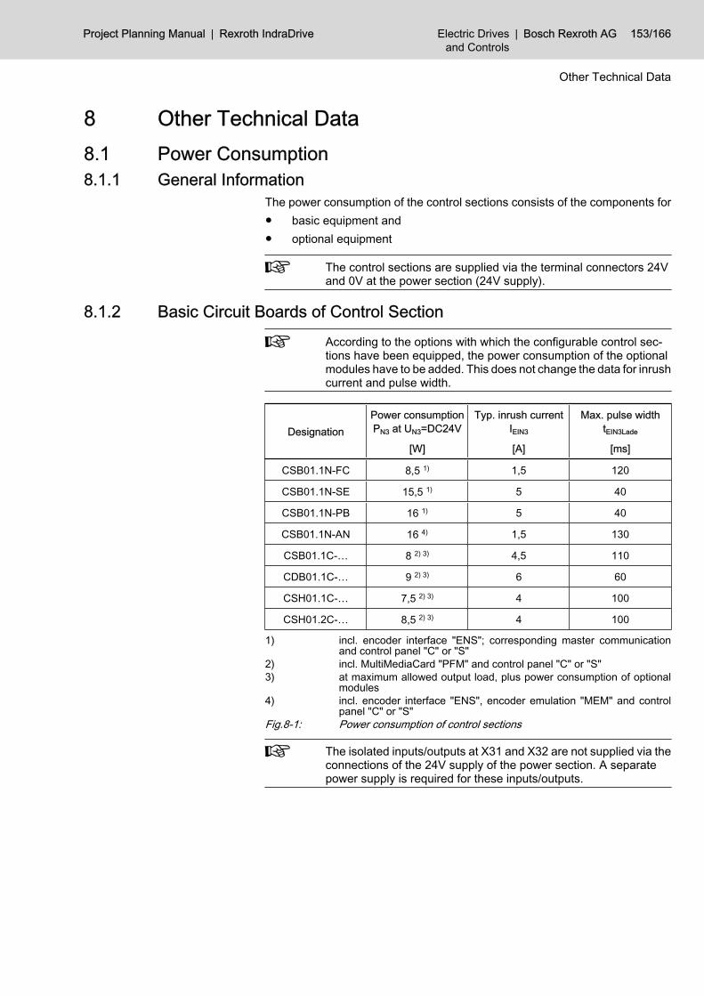
8 Other Technical Data8.1 Power Consumption 8.1.1 General Information
The power consumption of the control sections consists of the components for● basic equipment and● optional equipment
The control sections are supplied via the terminal connectors 24Vand 0V at the power section (24V supply).
8.1.2 Basic Circuit Boards of Control SectionAccording to the options with which the configurable control sec‐tions have been equipped, the power consumption of the optionalmodules have to be added. This does not change the data for inrushcurrent and pulse width.
DesignationPower consumptionPN3 at UN3=DC24V
[W]
Typ. inrush currentIEIN3
[A]
Max. pulse widthtEIN3Lade
[ms]
CSB01.1N-FC 8,5 1) 1,5 120
CSB01.1N-SE 15,5 1) 5 40
CSB01.1N-PB 16 1) 5 40
CSB01.1N-AN 16 4) 1,5 130
CSB01.1C-… 8 2) 3) 4,5 110
CDB01.1C-… 9 2) 3) 6 60
CSH01.1C-… 7,5 2) 3) 4 100
CSH01.2C-… 8,5 2) 3) 4 100
1) incl. encoder interface "ENS"; corresponding master communicationand control panel "C" or "S"
2) incl. MultiMediaCard "PFM" and control panel "C" or "S"3) at maximum allowed output load, plus power consumption of optional
modules4) incl. encoder interface "ENS", encoder emulation "MEM" and control
panel "C" or "S"Fig.8-1: Power consumption of control sections
The isolated inputs/outputs at X31 and X32 are not supplied via theconnections of the 24V supply of the power section. A separatepower supply is required for these inputs/outputs.
Project Planning Manual | Rexroth IndraDrive Electric Drivesand Controls
| Bosch Rexroth AG 153/166
Other Technical Data

8.1.3 Optional Modules Option1) Optional module Power consump‐
tion PN3 atUN3=DC24V2)
[W]
C comfort control panel 1
CCD cross communication SERCOS III
CO master communication DeviceNet and CANopen
MD1 digital I/O extension
MD2 digital I/O extension and SSI encoder evaluation
PL master communication parallel interface
S standard control panel
S1 safety technology I/O
S3 master communication SERCOS III
MEM encoder emulator 2
L1 starting lockout
SE master communication SERCOS
MA1 analog I/O extension
PB master communication PROFIBUS-DP
EN1 HSF, resolver 6
EN2 EnDat2.1 / 1 Vpp / 5 V TTL
ENS IndraDyn, HIPERFACE®, 1 Vpp
1) code from the control section type codes2) at maximum allowed output load, plus circuits to be supplied externallyFig.8-2: Power consumption of optional modules
8.2 Connections8.2.1 General Information
The connection points at Rexroth IndraDrive control sections are equipped withspring terminals and screw terminal blocks.
To connect 2 conductors in one terminal connecting point:● use stranded wires with min. 0.5 mm2 and max. 1.0 mm2
● use wires of the same cross section● use TWIN ferrules
8.2.2 Connections with Spring Terminals Spring terminals can be wired with wire ends equipped with or without fer‐rules. Preferably use wire ends without ferrules.When assembling the connections, make sure● that all strands of a stranded wire are placed in the funnel of the terminal
connector.
154/166 Bosch Rexroth AG | Electric Drivesand Controls
Rexroth IndraDrive | Project Planning Manual
Other Technical Data

● not to use solid wires, where possible.● that the cross section which can be connected at the spring terminals is
max. 1 mm2.● to use appropriate crimping tools for the wire ends with ferrules.
8.2.3 Connections with Screw Terminal Blocks On screw terminal blocks, use wire ends with ferrules. Make sure to use ap‐propriate crimping tools.When assembling the connections, make sure that all strands of a strandedwire are placed in the funnel of the terminal connector.
Project Planning Manual | Rexroth IndraDrive Electric Drivesand Controls
| Bosch Rexroth AG 155/166
Other Technical Data

Bosch Rexroth AG | Electric Drivesand Controls
Rexroth IndraDrive | Project Planning Manual

9 AccessoriesThe following accessories are available for control sections:● HAS05.1‑003 “signal level converter for encoder emulation” ● HAS05.1-005 “signal level converter RS232/RS485” The accessories are described in the “Rexroth IndraDrive, Drive System - Proj‐ect Planning Manual” documentation.
Project Planning Manual | Rexroth IndraDrive Electric Drivesand Controls
| Bosch Rexroth AG 157/166
Accessories

Bosch Rexroth AG | Electric Drivesand Controls
Rexroth IndraDrive | Project Planning Manual

10 Disposal and Environmental Protection10.1 Disposal10.1.1 Products
Our products can be returned to us free of charge for disposal. It is a precon‐dition, however, that the products are free of oil, grease or other dirt.Furthermore, the products returned for disposal mustn't contain any undue for‐eign matter or foreign component.Please send the products free domicile to the following address:Bosch Rexroth AGElectric Drives and ControlsBürgermeister-Dr.-Nebel-Straße 2D-97816 Lohr am Main
10.1.2 Packaging MaterialsThe packaging materials consist of cardboard, wood and polystyrene. Thesematerials can be easily recycled in any municipal recycling system. For eco‐logical reasons, please refrain from returning the empty packages to us.
10.2 Environmental Protection10.2.1 No Release of Hazardous Substances
Our products do not contain any hazardous substances which may be releasedin the case of appropriate use. Accordingly, our products will normally not haveany negative effect on the environment.
10.2.2 Materials Contained in the ProductsElectronic Devices
Electronic devices mainly contain:● steel● aluminium● copper● synthetic materials● electronic components and modules
MotorsMotors mainly contain:● steel● aluminium● copper● brass● magnetic materials● electronic components and modules
Project Planning Manual | Rexroth IndraDrive Electric Drivesand Controls
| Bosch Rexroth AG 159/166
Disposal and Environmental Protection

10.2.3 RecyclingDue to their high content of metal, most of the product components can berecycled. In order to recycle the metal in the best possible way, the productsmust be disassembled into individual modules.Metals contained in electric and electronic modules can also be recycled bymeans of special separation processes. The synthetic materials remaining afterthese processes can be thermally recycled.If the products contain batteries or accumulators, these have to be removedbefore recycling and disposed of.
160/166 Bosch Rexroth AG | Electric Drivesand Controls
Rexroth IndraDrive | Project Planning Manual
Disposal and Environmental Protection

11 Service & Support11.1 Helpdesk
Our service helpdesk at our headquarters in Lohr, Germany, will assist you withall kinds of enquiries.Contact us:● By phone through the Service Call Entry Center,
Mo - Fr 7:00 am - 6:00 pm CET+49 (0) 9352 40 50 60
● By Fax+49 (0) 9352 40 49 41
● By email: [email protected]
11.2 Service HotlineOut of helpdesk hours please contact our German service department directly:+49 (0) 171 333 88 26or+49 (0) 172 660 04 06Hotline numbers for other countries can be found in the addresses of eachregion (see below).
11.3 InternetAdditional notes regarding service, maintenance and training, as well as thecurrent addresses of our sales and service offices can be found onhttp://www.boschrexroth.comOutwith Germany please contact our sales/service office in your area first.
11.4 Helpful InformationFor quick and efficient help please have the following information ready:● detailed description of the fault and the circumstances● information on the type plate of the affected products, especially type co‐
des and serial numbers● your phone / fax numbers and e-mail address so we can contact you in
case of questions
Project Planning Manual | Rexroth IndraDrive Electric Drivesand Controls
| Bosch Rexroth AG 161/166
Service & Support

Bosch Rexroth AG | Electric Drivesand Controls
Rexroth IndraDrive | Project Planning Manual

IndexAAccessories 157ADVANCED
Control section 64ADVANCED CSH01.1C
Connections 69Optional slots 75
ADVANCED CSH01.2C 76Connections 77Optional slots 84
Analog I/O extension MA1 125Analog inputs
Technical data 145Type 1 145Type 2 146Type 3 146Type 4 147
Analog outputsTechnical data 148Type 1 148Type 2 148Type 3 149
Appropriate use 7Applications 7
BBASIC
Control section 23BASIC ANALOG CSB01.1N-AN
Connections 43BASIC OPENLOOP CSB01.1N-FC
Connections 29BASIC PROFIBUS CSB01.1N-PB
Connections 38BASIC SERCOS CSB01.1N-SE
Connections 33BASIC UNIVERSAL double-axis CDB01.1C
Connections 55BASIC UNIVERSAL double-axis CDB01.1C
Optional slots 62BASIC UNIVERSAL single-axis CSB01.1C
Connections 48Optional slots 53
Box with project planning manuals 3
CC
Optional module 137Cable
IKB0041 150IKS4038 117IKS4042 113IKS4043 112RKG0014 117RKG4200 107
RKG4400 133RKG4401 133RKS0001 135RKS0004 132
CANopen 96, 99CCD
Optional module 103CD
Optional module 99CDB01
Connections 55CDB01.1C
Optional slots 62Type code 25
COOptional module 96
Comfort control panel 137Configurability 21Connection diagrams
Analog inputs/outputs 144RS232 150Serial interface 150
ConnectionsADVANCED CSH01.1C 69ADVANCED CSH01.2C 77BASIC ANALOG CSB01.1N-AN 43BASIC OPENLOOP CSB01.1N-FC 29BASIC PROFIBUS CSB01.1N-P 38BASIC SERCOS CSB01.1N-SE 33BASIC UNIVERSAL double-axis CDB01.1C 55BASIC UNIVERSAL single-axis CSB01.1C 48With screw terminal blocks, notes 155With spring terminals, notes 154
Control panelComfort control panel 137Standard control panel 136
Control sectionADVANCED 64BASIC 23Configurability 21Delivery 4Mounting and dismounting 5Optional modules 87Overview - functions and interfaces 21Overview - types 21Power consumption 153Power dissipation 153Type code ADVANCED CSH01.1C 64Type code ADVANCED CSH01.2C 66Type code BASIC 23Type plate 20
Cross communication 103CSB01.1C
Connections 48Optional slots 53
Project Planning Manual | Rexroth IndraDrive Electric Drivesand Controls
| Bosch Rexroth AG 163/166
Index

CSB01.1NType code 23
CSB01.1N-ANConnections 43
CSB01.1N-FCConnections 29
CSB01.1N-PBConnections 38
CSB01.1N-SEConnections 33
CSH01.1CConnections 69Optional slots 75Type code 64
CSH01.2C, 76Connections 77Optional slots 84Type code 66
DDelivery
Control section 4DeviceNet 96, 99Digital I/O extension MD1 128Digital I/O extension MD2 129Digital inputs
Probe 141, 142Technical data 140
Digital outputsTechnical data 143
Dimensional drawingControl section double-axis 28Control section single-axis 27
DimensionsADVANCED 68BASIC double-axis 28BASIC single-axis 27
DismountingControl section 5
DocumentationStructure 1
DocumentationsOverview 2
Drive controllerControl section 4Design 4Power section 4Type plates 19
EEN1
Optional module 109EN2
Optional module 113Encoder cable length, allowed
EN2 118ENS 109
Encoder emulationVoltage signal level converter 157
Encoder emulation MEM 120Encoder evaluation
EN2 113Resolver and HSF encoder evaluation EN1 109SSI 129Standard encoder evaluation ENS 104
Engineering interface 151ENS
Optional module 104
FFirmware
Type plate 20Functions and interfaces
Overview 21
HHall sensor box 109HAS05.1-
005 157
II/O extension
Analog, MA1 125Digital, MD1 128Digital, MD2 129
IdentificationOf the control section 19
Inappropriate use, 8Consequences, exclusion of liability 7
InterfacesOverview 21
LL1
Optional module 134
MMA1
Optional module 125Marking the components 19Master communication
Cross communication - CCD 103DeviceNet / CANopen - CD 99DeviceNet / CANopen - CO 96Parallel interface - PL 93PROFIBUS - PB 89SERCOS III - S3 101SERCOS - SE 88
MD1Optional module 128
MD2Optional module 129
MEMOptional module 120
164/166 Bosch Rexroth AG | Electric Drivesand Controls
Rexroth IndraDrive | Project Planning Manual
Index

Memory card PFM02.1 138MMC 138Mounting
Control section 5
OOptional module
C 137CCD 103CD 99CO 96EN1 109EN2 113ENS 104L1 134MA1 125MD1 128MD2 129MEM 120Overview 87PB 89PFM02.1 138PL 93S 136S3 101Safety technology S1 135SE 88
Optional modulesPower consumption 154
Optional slotsADVANCED CSH01.1C 75ADVANCED CSH01.2C 84BASIC UNIVERSAL double-axis CDB01.1C 62BASIC UNIVERSAL single-axis CSB01.1C 53
PParallel interface 93PB
Optional module 89PFM02.1 138PL
Optional module 93Power consumption 153
Basic circuit boards of control section 153Optional modules 154
Power dissipationControl section 153Optional modules 154
Probe 141, 142PROFIBUS 89Project planning manuals
Box 3
RRelay contacts 139
Type 1 139Type 2 139
Type 3 140Resolver and HSF encoder evaluation EN1 109RS232
Serial interface 149RS232/485
Signal level converter 157
SS
Optional module 136S1
Optional module 135S3
Optional module 101safety instructions for electric drives and controls 9Safety technology
S1 135Starting lockout L1 134
Screw terminal blocksNotes 155
SEOptional module 88
SERCOS 88SERCOS III 101Serial interface RS232 149SHL
Hall sensor box 109Signal level converter
Voltage signal level converter (for encoder emu‐lation) 157
Signal level converter RS232/485 157Spring terminals
Connections, notes 154SSI encoder evaluation MD2 129Standard control panel 136Standard encoder evaluation ENS 104Starting lockout L1 134State-of-the-art 7
TTechnical data
Analog inputs 145Analog outputs 148Digital inputs 140Digital outputs 143Dimensions control section BASIC double-axis28Dimensions control section BASIC single-axis27Engineering interface 151Power dissipation 153Relay contacts 139Serial interface RS232 149
Type codeADVANCED CSH01.1C 64ADVANCED CSH01.2C 66BASIC 23
Project Planning Manual | Rexroth IndraDrive Electric Drivesand Controls
| Bosch Rexroth AG 165/166
Index

CDB01.1C 25CSB01.1N 23CSH01.1C 64CSH01.2C 66
Type platesAt the drive controller 19
UUse
Appropriate use 7Inappropriate use 8
166/166 Bosch Rexroth AG | Electric Drivesand Controls
Rexroth IndraDrive | Project Planning Manual
Index

Notes
Project Planning Manual | Rexroth IndraDrive Electric Drivesand Controls
| Bosch Rexroth AG

Bosch Rexroth AGBgm.-Dr.-Nebel-Str. 2D-97816 Lohr a. [email protected]
Printed in GermanyDOK-INDRV*-CSH********-PR06-EN-P