Embed Size (px)
Citation preview
1
Control of a wind farm based on synchronousgenerators with a central HVDC-VSC converterOriol Gomis-Bellmunt, Member, IEEE, Adria Junyent-Ferre, Student Member, IEEE, Andreas Sumper,
Member, IEEE, and Joan Bergas-Jane, Member, IEEE
Abstract—A control scheme for wind farms based on syn-chronous generators connected to a single power converter ispresented. The scheme is applicable to HVDC interfaced offshoreor remote wind farms. The proposed control scheme is based oncomputing the optimal wind farm electrical frequency dependingon the different incoming wind speeds. The power converterregulates the system frequency by adjusting the power injectedto the HVDC circuit. Fault ride-through is also possible byreducing rapidly the injected active power. The proposed schemeis validated by means of simulations with a wind farm composedof four wind turbines.
Index Terms—Wind power generation, High voltage directcurrent (HVDC), Variable frequency wind farm, Offshore windpower.
I. INTRODUCTION
Onshore wind farms are nowadays capable of not onlygenerating power, but provide support to the grid where theyare connected providing ancillary services [1] or contributingto power system stability [2] while riding through faults in thegrid [3], [4]. Onshore wind farms can actually be consideredas wind power plants as they can be operated as conventionalpower plants [5].
Remote and offshore wind farms need HVDC or HVAClines to interface them to the main grid [6]. Above a certaincritical distance, HVDC technology stands as the appropriatesolution, which can be based on Line Commutated ConvertersHVDC-LCC [7]–[9] or Voltage Source Converters HVDC-VSC [10]–[12]. In both cases, HVDC systems require apower converter at the connection point of the wind farms,allowing a centralized control for the whole wind farm. Someoffshore wind farms employ only this central power converterwith squirrel cage induction generators [13] or synchronousgenerators [14], [15], while others combine a central powerconverter with individual converters and doubly fed inductiongenerators [12] in each wind turbine.
Jovcic [14], [15] proposed a variable frequency wind farmgrid to maximize power generation, based on the approach of[16], which is well demonstrated for a single wind turbine:applying a power reference P ∗ = Kω3 or the equivalent
This work was supported by the Ministerio de Ciencia e Innovacion underthe project ENE2009-08555.
The authors are with Centre d’Innovacio Tecnologica en ConvertidorsEstatics i Accionaments (CITCEA-UPC), Departament d’Enginyeria Electrica,Universitat Politecnica de Catalunya. ETS d’Enginyeria Industrial deBarcelona, Av. Diagonal, 647, Pl. 2. 08028 Barcelona, Spain Tel: +34934016727, Fax: +34 934017433, e-mail: [email protected]. Oriol Gomis-Bellmunt and Andreas Sumper are also with Catalonia Institute for EnergyResearch IREC.
torque reference T ∗ = Kω2 [17], [18] with the appropriateconstant K, the wind turbine generation is maximized. Thisapproach is broadly used for maximum power point trackingof a single wind turbine controlled by a dedicated powerconverter. However, the performance of this approach is notdemonstrated for a wind farm with multiple wind turbines anda single power converter, when the different wind turbinesare generating at different wind speeds. Other authors [13]proposed methods to dynamically search the maximum gener-ation by changing frequency and observing power changes, butthese methods present the drawback of possible operation atlocal maximums, that may generate much less power than anabsolute maximum in certain cases. Therefore, the mentionedapproaches do not guarantee maximum power generation forall wind speeds in the case of a wind farm connected to asingle power converter. The present work proposes a techniqueto assure maximum power extraction in an offshore windfarm based on synchronous generators connected to a singlepower converter. Maximum generation power is obtained bycomputing the optimal wind farm grid electrical frequencydepending on the measured wind speeds in all the windturbines. A frequency controller is implemented to obtain theoptimal frequency by adjusting the power converter power.It is important to stress that the term maximum generationpower, used throughout the paper, means maximum generationfor the chosen topology, i.e. wind farm connected to a singlepower converter. It is clear that the only possible way of gettingall the available power is using dedicated converters for eachmachine.
Offshore wind farms connected by means of HVDC haveto reduce power rapidly when faults onshore occur in orderto prevent overvoltages in HVDC circuits. Moreover, thishas to be done without using fast communication systems toassure system reliability. Several solutions have been proposedrecently [19], [20], including the use of braking resistors todissipate the power, wind farm frequency increase to reducepower generation letting the wind turbines accelerate, windfarm voltage reduction or directly reducing the power in theconverter. Although, the last method is usually not convenientto avoid current and voltage transients in the operation modeswitching, the present work achieves fault ride-through byreducing directly the power in main HVDC-VSC converter.This is possible without important transients because theproposed control scheme is based on controlling directly thepower in the HVDC-VSC and therefore no operation modechange is required to reduce the power injected in the HVDCcircuit.
2
The present work presents a control scheme for wind farms(or clusters or wind turbines inside a wind farm) with windturbines based on synchronous generators connected to asingle HVDC-VSC converter. The configuration can be usedfor HVDC connections (with an already existing HVDC-VSC converter) and also with full power back to back powerconverters. The main advantage of the proposed configurationis that no power converters are required in the individualwind turbines and therefore cost is reduced and reliability isincreased. The drawbacks include the lost of part of the windenergy when wind speeds are different (discussed in SectionII), the need for auxiliary power converters to supply auxiliaryequipment in the wind turbines and the more reduced controlcapability over the wind turbine mechanical system, comparedto the use of individual power converters.
The proposed control scheme can be used both with perma-nent magnet synchronous generators (PMSG) and wound rotorsynchronous generators (WRSG). For PMSG, the generatorflux is created by a rotating magnet and therefore individualwind turbines are not capable of controlling it. For WRSG,the flux can be controlled adjusting the rotor current, howeverfor the present work a constat rotor current is assumed andtherefore the behavior of both PMSG and WRSG wind farmswould be equivalent. The control scheme operates the windfarm to maximize power generation in normal conditions andreduces the power injection when a fault onshore occurs. Theproposed scheme has been validated by means of simulations.
The paper is organized as follows. In Section II the conve-nience of the wind farm grid with a single power converter isdiscussed considering wind speed variability in wind farms. InSection III the optimum electrical frequency search procedureis described. Section IV analyzes electrically the proposedscheme. The proposed control scheme is introduced in SectionV and simulated in Section VI. The conclusions are summa-rized in Section VII.
II. COMPARISON OF THE POWER EXTRACTED BY A WINDFARM WITH A SINGLE CENTRAL POWER CONVERTER AND
INDIVIDUAL CONVERTERS IN EACH WIND TURBINE
Wind variability in wind farms is difficult to analyze in ageneral way, since it depends heavily on wind turbine locationsand incoming wind directions. However, it is possible toundergo a statistical analysis in order to evaluate the effectof wind variation in terms of maximum available powerconsidering the use of a single converter for the whole windfarm or dedicated converters for each wind turbine.
The present section uses an evaluation methodology toevaluate the wind power generated using the three followingconcepts:
• A Wind farm with a single power converter and variablefrequency
• B Wind farm with constant frequency (50 Hz)• C Wind farm with individual power converters in each
wind turbineThe evaluation methodology consists in a massive analysis
of different scenarios in order to extract conclusions aboutthe amount of power generated by the different concepts. Themethodology is based on a two-level approach:
• In the first level a set of wind speeds is generated.According to the data provided by means of Weibulldistribution parameters, the average wind farm windspeed is generated randomly. With this average value andthe typical deviation the individual wind turbines speedsare generated randomly using a Normal distribution. Thedifferent wind speeds sets are generated Nsim times fordifferent Nsd standard deviations values to be analyzed.Therefore a total number of Nsim×Nsd wind speeds setare generated.
• In the second level, the generated power for the differ-ent configurations is analyzed. Each wind speeds set isanalyzed for different electrical frequencies: for a givenwind speeds set, a sweep of Nfreq electrical frequenciesis undergone, calculating for each of them the equilibriumpoint and the electrical power generated. As a result of theanalysis the following total powers are computed: maxi-mum available power Pcp (only obtained using individualpower converters in each wind turbine), maximum powerusing a single power converter with variable frequencyPpc and power generated with a constant frequency grid(50 Hz) P50. Summing the powers obtained for theNsim simulations, the ratios αpc =
∑Ppc/
∑Pcp and
α50 =∑P50/
∑Pcp are calculated for each different
standard deviation.
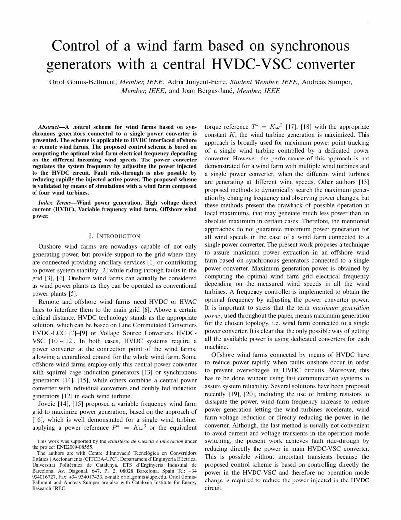
The methodology has been applied to the wind farm de-scribed in the Appendix, considering a Weibull distributiondata from [21], [22] (a = 9.02, b = 2.26) and differentstandard deviations between 0.5 and 10 m/s (Nsd = 20).The simulations have been performed with Nfreq = 100 andNsim = 200. The results are shown in Fig. 1. Initially, fora standard deviation of 0.5 m/s, αpc is 0.9979 and α50 is0.802. Therefore for low standard deviations (similar windspeeds throughout the wind farm), the performance of thesingle power converter with variable frequency is excellent.When the standard deviation is increased the performance ofboth single power converter based methods is decreased dueto the larger wind speed variability, however the single powerconverter with variable frequency concept maintains αpc above0.95 until the standard deviation is larger than 2.5 m/s, whichis larger than typical values of less than 1 m/s [23]. Even fora huge standard deviation of 10 m/s, the value of αpc 0.7827is acceptable. In all the cases, the performance of the singlepower converter with variable frequency is between 0.19 and0.38 better than the constant frequency grid.
Similar analysis for wind farms with different number ofwind turbines shows similar results. For 10 wind turbines, withstandard deviation of 2 m/s, α50 is 0.75 and αpc 0.95. Withstandard deviation of 5 m/s, α50 is 0.57 and αpc 0.82. For 20wind turbines, with standard deviation of 2 m/s, α50 is 0.71and αpc 0.94. With standard deviation of 5 m/s, α50 is 0.55and αpc 0.8. For larger number of wind turbines the results arevery similar to the 20 wind turbine wind farm. It can be seenthat a larger number of wind turbines reduces the generatedpower. This effect can be overcome by appropriately clusteringthe wind turbines.
3
0 1 2 3 4 5 6 7 8 9 100.4
0.5
0.6
0.7
0.8
0.9
1
Standard Deviation [m/s]
Rat
io α
pc a
nd α
50
αpc
α50
Fig. 1. Dependance of the ratios αpc and α50 on the standard deviation ofthe wind speeds inside the wind farm
III. OPTIMUM ELECTRICAL FREQUENCY SEARCH
A. Wind turbine power generation
The power Pwti generated by a wind turbine can be writtenas Pwti = CpPwind = 1
2CpρAv3w where Pwind is the air
stream kinetic power, ρ is the air density, A = πR2 is thesurface covered by the wind wheel of radius R, vw is theaverage wind speed and Cp is the power coefficient, whichcan be written as [24]:
Cp (λ, θpitch) = c1
(c2
1
Λ− c3θpitch − c4θ
c5pitch − c6
)e−c7
1Λ
(1)where θpitch is the pitch angle and λ is the so called tipspeed ratio defined as λ = ωtR
vwwhere ωt is the wind turbine
speed and 1Λ = 1
λ+c8θpitch− c9
1+θ3pitch
where [c1 . . . c9] arecharacteristic constants for each wind turbine.
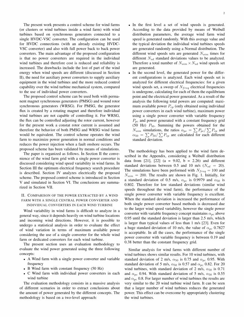
A typical Cp− λ curve is sketched in Fig. 2. The Cp− λcurve has a maximum value which corresponds to the optimumoperating point of the wind turbine as long as the wind speeddoes not overcome the maximum threshold.
In a single wind turbine, the maximum CP is obtained[17], [18] when Twti = Kω2
t (K depends on the coefficientsci) which guarantees maximum power generation for a singlewind turbine, but it cannot be directly applied to a whole windfarm with different wind speeds.
B. Wind farm generation analysis
The total power generated by a wind farm composed of Nwtwind turbines can be expressed as Pwf =
∑Nwt
i=1 Pwti. Withoutloss of generality, all the wind turbines can be consideredidentical and therefore all the wind turbine constants will keepthe same values for all the wind farm. In this case, the totalpower generated Pwf = 1
2ρA∑Nwt
i=1 CPiv3wi, where it can be
noted that CPi and vwi can be different for the different windturbines and therefore it is not possible to operate all themachines at the optimum operating point except when theyare all working with the same wind speed.
A typical example of a multi wind turbine wind farm isshown in Fig. 2. Four operation points for four wind turbines
0 2 4 6 8 10 12 14 16 18 200
0.05
0.1
0.15
0.2
0.25
0.3
0.35
0.4
0.45
0.5
1
2
3
4
Tip speed ratio λ
Pow
er c
oeffi
cien
t Cp
Fig. 2. Cp − λ curve for different wind turbines generating with differentwind speeds with electrical frequency of 50 Hz. The wind turbine parametersof Appendix are used.
with different wind speeds are shown. The different windspeeds imply different λ and Cp and therefore it can be seenclearly that it is not possible to operate all the wind turbines atthe maximum Cp. The four different wind turbine operatingpoints correspond to the following data: 1 vw=5 m/s, Cp=0.189, Pelec= 0.0409 MW, 2 vw=13 m/s, Cp= 0.381, Pelec=1.52 MW, 3 vw=9.7 m/s, Cp= 0.485, Pelec= 0.767 MW, 4vw=6.2 m/s, Cp= 0.368, Pelec= 0.152 MW.
C. Optimum electrical frequency search
In order to generate the maximum possible energy in awind farm, it is proposed to modify the electrical wind farmfrequency and consequently the wind turbines speed. To findthe electrical frequency that maximizes the total power of thewind farm (circular marker of Fig. 3), it is proposed to expressthe Cp expression (1) as a polynomial of degree Npol andcoefficients aj
Cp(λ) =
Npol∑j=0
ajλj =
Npol∑j=0
aj(ωtR)
j
vjw(2)
where θpitch has been assumed to be the minimum value(zero) as the maximum power is to be extracted. The powergenerated by each turbine i can be expressed as
Pwt−i =1
2ρAv3
wi
Npol∑j=0
aj(ωtR)
j
vjwi(3)
For each synchronous generator, the wind turbine speed insteady state conditions can be written as ωt = ωe
PNmultwhere
ωe is the grid electrical angular speed, P is the pole pairsnumber and Nmult is the multiplier factor. Substituting it inexpression (3), rearranging and summing all the wind turbinepower, the total wind farm power yields
Pwf =1
2ρA
Nwt∑i=1
Npol∑j=0
aj
(R
PNmult
)jωjev
3−jwi (4)
To determine the electrical angular speed ωe that maximizesthe total generated power, one can evaluate dPwf
dωe= 0 which
4
can also be expressed asNpol∑j=1
bjωj−1e = 0, bj = 1
2ρAjaj
(R
PNmult
)j∑Nwt
i=1 v3−jwi (5)
Solving (5), Npol− 1 solutions are found, the obtained realsolutions can be substituted in the total power equation (4) inorder to determine which is the optimal solution.
It is important to note that the computational time neededto solve (5) can be expressed as the sum of the time Tcom−bjneeded to calculate the parameters bj and the time Tcom−eqneeded to solve the equation. Tcom−bj can be expressed asTcom−bj = NpolTb where Tb is proportional to the number ofwind turbines Nwt. On the other hand, since the equation isa polynomial of degree Npol − 1 with a single unknown ωe,Tcomeq depends only on the degree of the polynomial and notin the number of wind turbines. Using a common computer,and considering Npol = 5, the optimal frequency of a windfarm of 198 wind turbines can be calculated in approximately100 ms and a wind farm of 1998 wind turbines in 1 second.
D. Application example
A wind farm composed of four wind turbines is analyzed,considering the parameters described in the Appendix.
The Cp − λ curve has been approximated to the fifthdegree polynomial −8.08×10⁻⁶λ5 +0.00042λ4−0.0078λ3 +0.053λ2 − 0.024λ− 0.176.
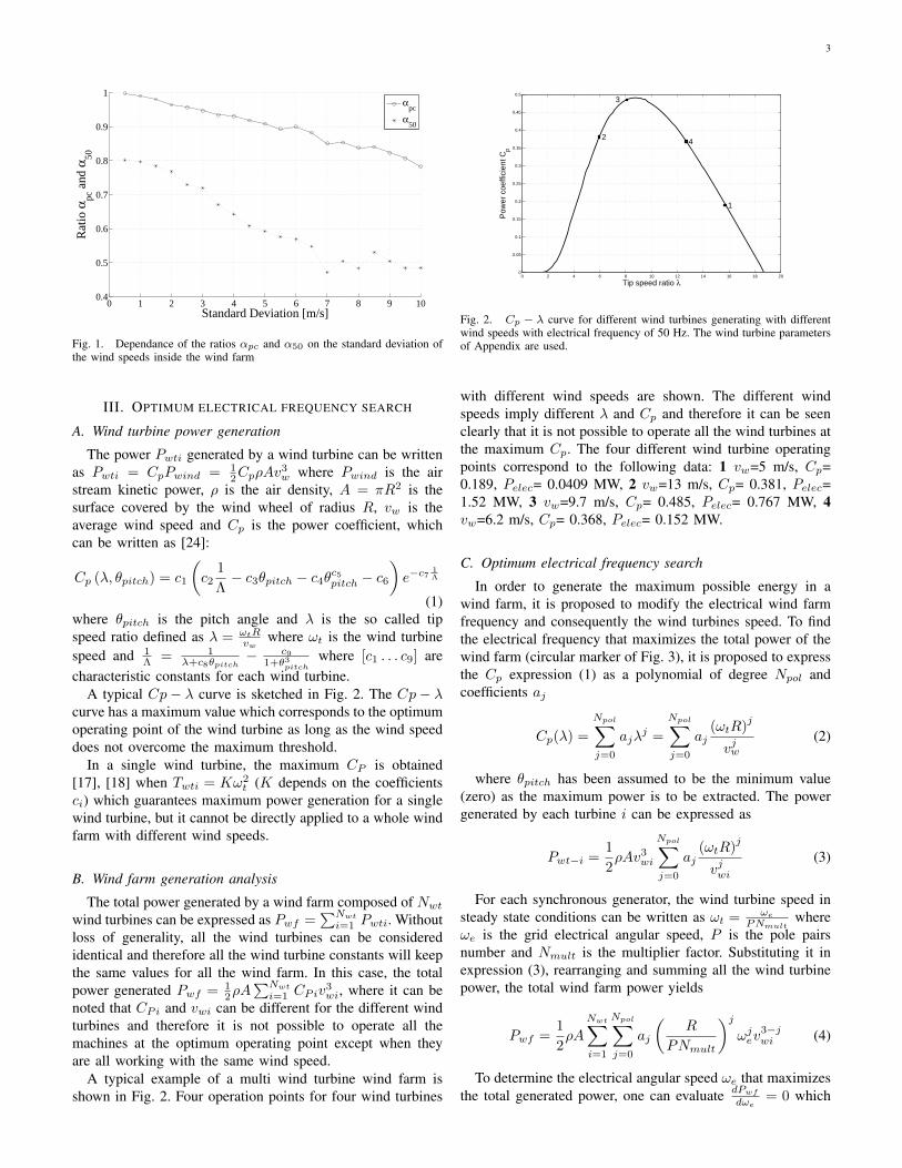
Wind speeds of 11.1 m/s, 13 m/s, 9.6 m/s and 8.2 m/shave been considered. Fig. 3 shows the power generated inthe wind farm depending on the electrical grid frequency.The bold black line shows the power generated for differentgrid electrical frequencies, whose maximum is illustrated bya circular marker.
In order to determine the optimum electrical frequency, theparameters bi have been computed according to (5) as func-tions of the wind turbines parameters and the incoming windspeeds. The optimal electrical frequency can be computedsolving the equation −3.6570 + 0.4930ωe − 0.0035ω2
e
+ 8.1861 × 10⁻⁶ω3e − 6.6126 × 10⁻⁹ω4
e = 0 whose solu-tions yield 467.95+j143.87, 467.95-j143.87, 294.21 and 7.84.Among these four solutions it is clear that the optimum ωeis 294.21 rad/s (which corresponds to 47.05 Hz), since twoof the other roots are complex numbers and the other onecorresponds to the minimum power. In a real time controlsystem, the Newton iteration method can be used to rapidlycompute the solution by choosing appropriate initial solutionssuch as 2π50 ≈ 314.16 rad/s.
IV. WIND FARM GRID CONNECTED TO A SINGLE POWERCONVERTER
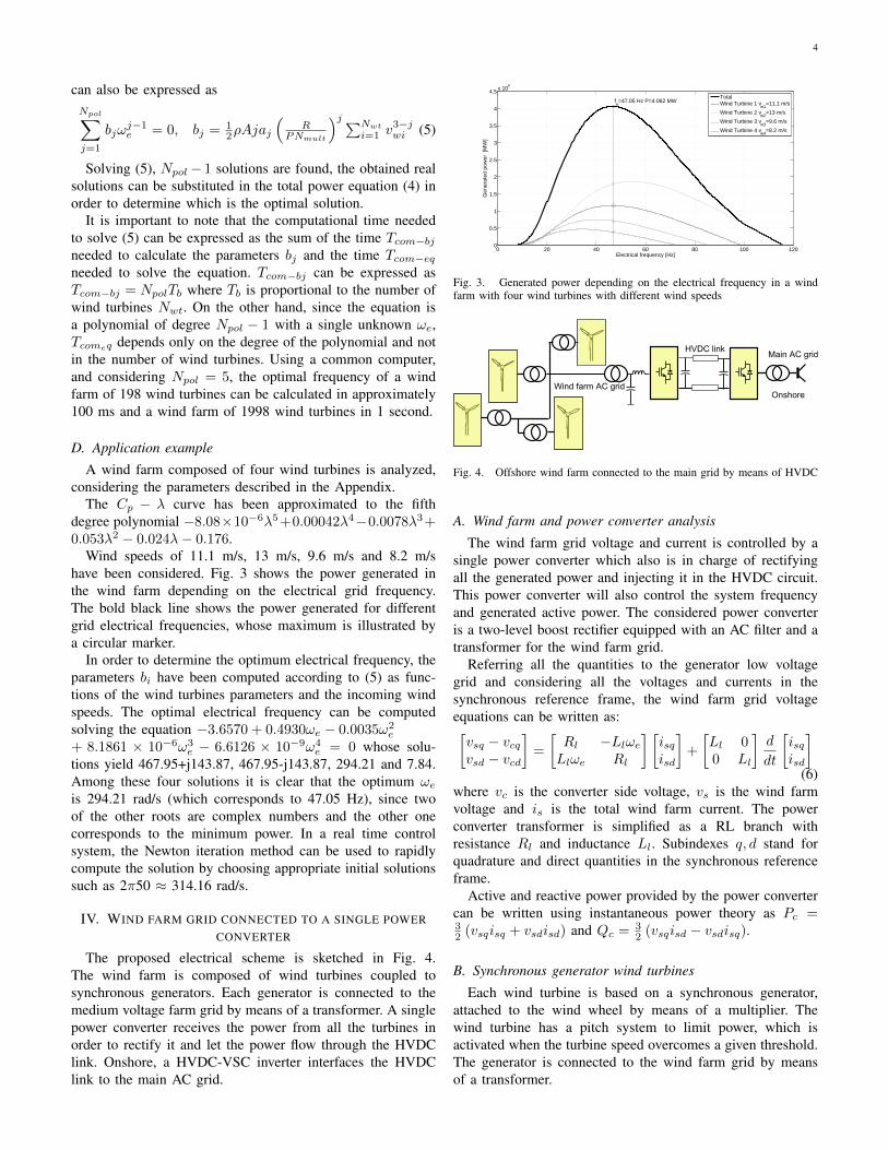
The proposed electrical scheme is sketched in Fig. 4.The wind farm is composed of wind turbines coupled tosynchronous generators. Each generator is connected to themedium voltage farm grid by means of a transformer. A singlepower converter receives the power from all the turbines inorder to rectify it and let the power flow through the HVDClink. Onshore, a HVDC-VSC inverter interfaces the HVDClink to the main AC grid.
0 20 40 60 80 100 1200
0.5
1
1.5
2
2.5
3
3.5
4
4.5x 10
6
Electrical frequency [Hz]
Gen
erat
ed p
ower
[M
W]
fe=47.05 Hz P=4.062 MW
TotalWind Turbine 1 v
w1=11.1 m/s
Wind Turbine 2 vw2
=13 m/s
Wind Turbine 3 vw3
=9.6 m/s
Wind Turbine 4 vw4
=8.2 m/s
Fig. 3. Generated power depending on the electrical frequency in a windfarm with four wind turbines with different wind speeds
OnshoreWind farm AC grid
Main AC gridHVDC link
Fig. 4. Offshore wind farm connected to the main grid by means of HVDC
A. Wind farm and power converter analysis
The wind farm grid voltage and current is controlled by asingle power converter which also is in charge of rectifyingall the generated power and injecting it in the HVDC circuit.This power converter will also control the system frequencyand generated active power. The considered power converteris a two-level boost rectifier equipped with an AC filter and atransformer for the wind farm grid.
Referring all the quantities to the generator low voltagegrid and considering all the voltages and currents in thesynchronous reference frame, the wind farm grid voltageequations can be written as:[vsq − vcqvsd − vcd
]=
[Rl −LlωeLlωe Rl
] [isqisd
]+
[Ll 00 Ll
]d
dt
[isqisd
](6)
where vc is the converter side voltage, vs is the wind farmvoltage and is is the total wind farm current. The powerconverter transformer is simplified as a RL branch withresistance Rl and inductance Ll. Subindexes q, d stand forquadrature and direct quantities in the synchronous referenceframe.
Active and reactive power provided by the power convertercan be written using instantaneous power theory as Pc =32 (vsqisq + vsdisd) and Qc = 3
2 (vsqisd − vsdisq).
B. Synchronous generator wind turbines
Each wind turbine is based on a synchronous generator,attached to the wind wheel by means of a multiplier. Thewind turbine has a pitch system to limit power, which isactivated when the turbine speed overcomes a given threshold.The generator is connected to the wind farm grid by meansof a transformer.
5
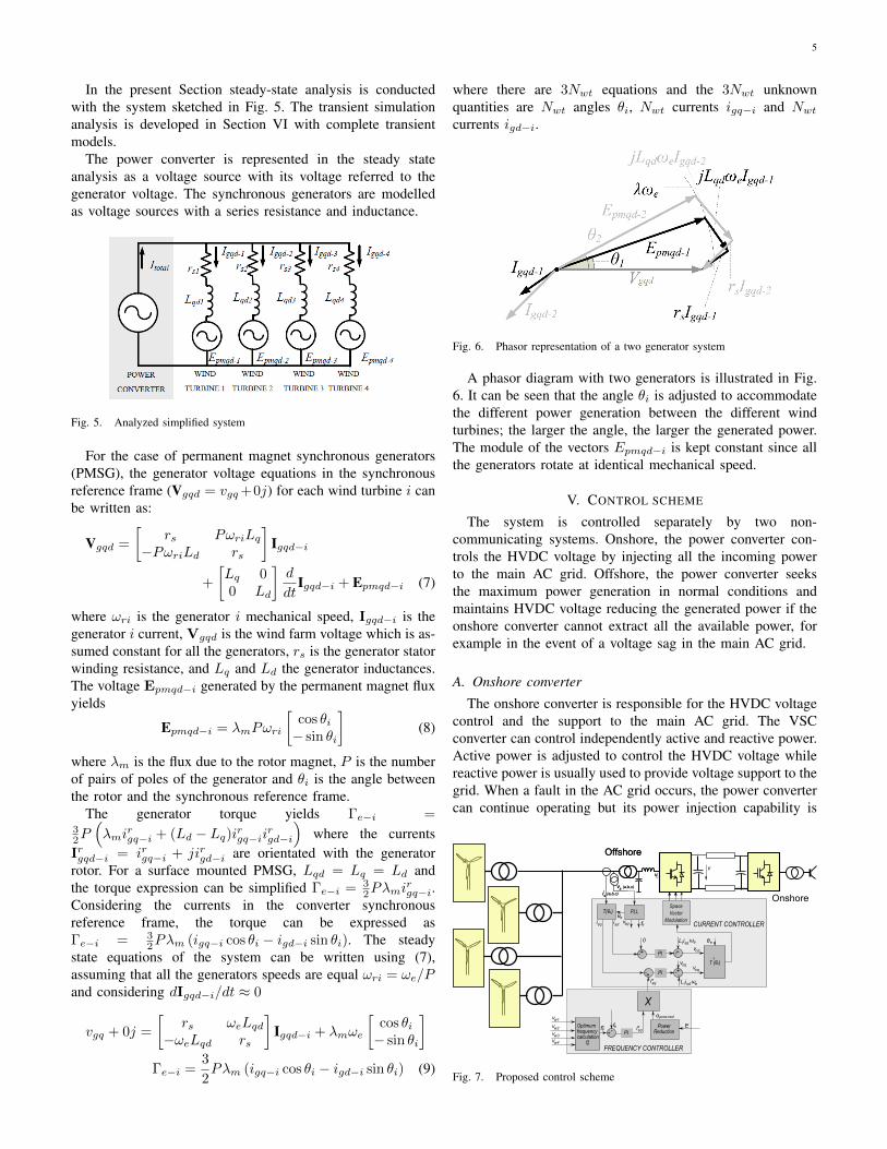
In the present Section steady-state analysis is conductedwith the system sketched in Fig. 5. The transient simulationanalysis is developed in Section VI with complete transientmodels.
The power converter is represented in the steady stateanalysis as a voltage source with its voltage referred to thegenerator voltage. The synchronous generators are modelledas voltage sources with a series resistance and inductance.
Fig. 5. Analyzed simplified system
For the case of permanent magnet synchronous generators(PMSG), the generator voltage equations in the synchronousreference frame (Vgqd = vgq+0j) for each wind turbine i canbe written as:
Vgqd =
[rs PωriLq
−PωriLd rs
]Igqd−i
+
[Lq 00 Ld
]d
dtIgqd−i + Epmqd−i (7)
where ωri is the generator i mechanical speed, Igqd−i is thegenerator i current, Vgqd is the wind farm voltage which is as-sumed constant for all the generators, rs is the generator statorwinding resistance, and Lq and Ld the generator inductances.The voltage Epmqd−i generated by the permanent magnet fluxyields
Epmqd−i = λmPωri
[cos θi− sin θi
](8)
where λm is the flux due to the rotor magnet, P is the numberof pairs of poles of the generator and θi is the angle betweenthe rotor and the synchronous reference frame.
The generator torque yields Γe−i =32P(λmi
rgq−i + (Ld − Lq)i
rgq−ii
rgd−i
)where the currents
Irgqd−i = irgq−i + jirgd−i are orientated with the generatorrotor. For a surface mounted PMSG, Lqd = Lq = Ld andthe torque expression can be simplified Γe−i = 3
2Pλmirgq−i.
Considering the currents in the converter synchronousreference frame, the torque can be expressed asΓe−i = 3
2Pλm (igq−i cos θi − igd−i sin θi). The steadystate equations of the system can be written using (7),assuming that all the generators speeds are equal ωri = ωe/Pand considering dIgqd−i/dt ≈ 0
vgq + 0j =
[rs ωeLqd
−ωeLqd rs
]Igqd−i + λmωe
[cos θi− sin θi
]Γe−i =
3
2Pλm (igq−i cos θi − igd−i sin θi) (9)
where there are 3Nwt equations and the 3Nwt unknownquantities are Nwt angles θi, Nwt currents igq−i and Nwtcurrents igd−i.
Fig. 6. Phasor representation of a two generator system
A phasor diagram with two generators is illustrated in Fig.6. It can be seen that the angle θi is adjusted to accommodatethe different power generation between the different windturbines; the larger the angle, the larger the generated power.The module of the vectors Epmqd−i is kept constant since allthe generators rotate at identical mechanical speed.
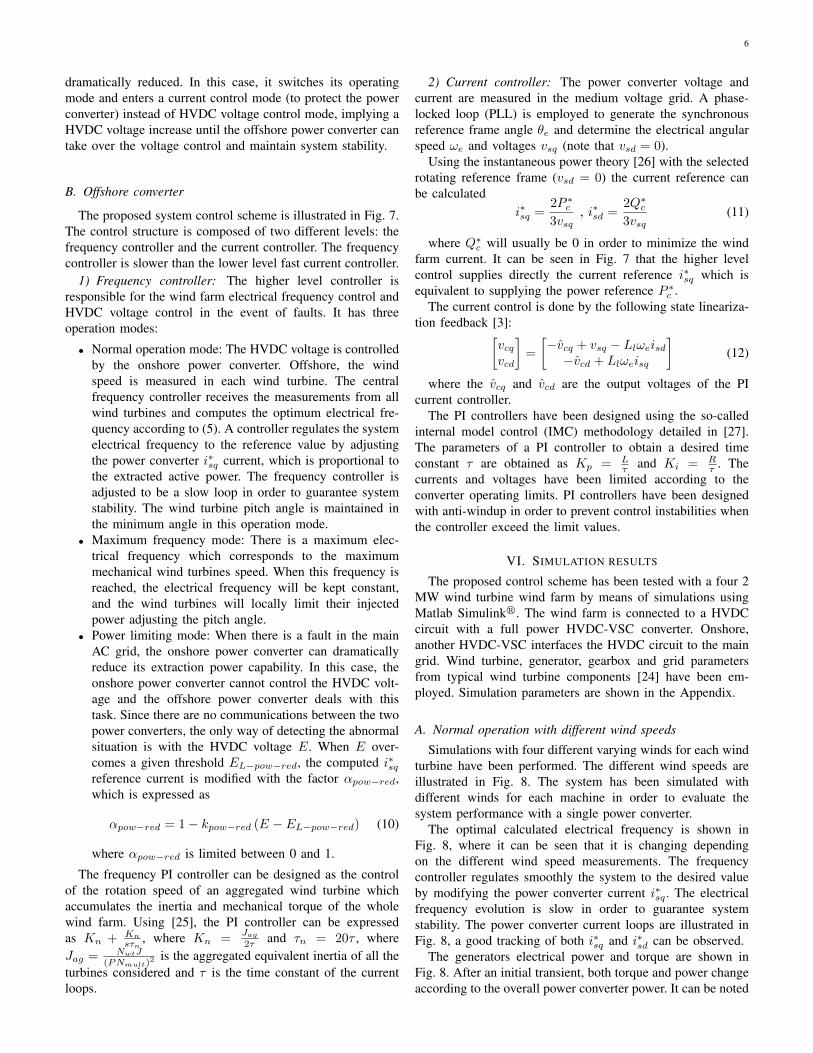
V. CONTROL SCHEME
The system is controlled separately by two non-communicating systems. Onshore, the power converter con-trols the HVDC voltage by injecting all the incoming powerto the main AC grid. Offshore, the power converter seeksthe maximum power generation in normal conditions andmaintains HVDC voltage reducing the generated power if theonshore converter cannot extract all the available power, forexample in the event of a voltage sag in the main AC grid.
A. Onshore converter
The onshore converter is responsible for the HVDC voltagecontrol and the support to the main AC grid. The VSCconverter can control independently active and reactive power.Active power is adjusted to control the HVDC voltage whilereactive power is usually used to provide voltage support to thegrid. When a fault in the AC grid occurs, the power convertercan continue operating but its power injection capability is
PLL
v (a,b,c)s
CURRENT CONTROLLER
Onshore
Offshore
T(θe)
vsqisq isd
+-
SpaceVector
Modulationθ
PI +- -L
e
T (θe)
θe
isdl ω
vsq
-1
vcq
vc
i (a,b,c)s
v (a,b,c)s
Offshore
v
i (a,b,c)s
i* sq
FREQUENCY CONTROLLER
Optimum frequencycalculation f*e
PI+-ff* e
e i* sq
fe
+- PI -+
L isql eω
vcd
0
v w1
v w2
v w3v w4
E
PowerReduction
E
Xα pow-red
e
Fig. 7. Proposed control scheme
6
dramatically reduced. In this case, it switches its operatingmode and enters a current control mode (to protect the powerconverter) instead of HVDC voltage control mode, implying aHVDC voltage increase until the offshore power converter cantake over the voltage control and maintain system stability.
B. Offshore converter
The proposed system control scheme is illustrated in Fig. 7.The control structure is composed of two different levels: thefrequency controller and the current controller. The frequencycontroller is slower than the lower level fast current controller.
1) Frequency controller: The higher level controller isresponsible for the wind farm electrical frequency control andHVDC voltage control in the event of faults. It has threeoperation modes:
• Normal operation mode: The HVDC voltage is controlledby the onshore power converter. Offshore, the windspeed is measured in each wind turbine. The centralfrequency controller receives the measurements from allwind turbines and computes the optimum electrical fre-quency according to (5). A controller regulates the systemelectrical frequency to the reference value by adjustingthe power converter i∗sq current, which is proportional tothe extracted active power. The frequency controller isadjusted to be a slow loop in order to guarantee systemstability. The wind turbine pitch angle is maintained inthe minimum angle in this operation mode.
• Maximum frequency mode: There is a maximum elec-trical frequency which corresponds to the maximummechanical wind turbines speed. When this frequency isreached, the electrical frequency will be kept constant,and the wind turbines will locally limit their injectedpower adjusting the pitch angle.
• Power limiting mode: When there is a fault in the mainAC grid, the onshore power converter can dramaticallyreduce its extraction power capability. In this case, theonshore power converter cannot control the HVDC volt-age and the offshore power converter deals with thistask. Since there are no communications between the twopower converters, the only way of detecting the abnormalsituation is with the HVDC voltage E. When E over-comes a given threshold EL−pow−red, the computed i∗sqreference current is modified with the factor αpow−red,which is expressed as
αpow−red = 1 − kpow−red (E − EL−pow−red) (10)
where αpow−red is limited between 0 and 1.
The frequency PI controller can be designed as the controlof the rotation speed of an aggregated wind turbine whichaccumulates the inertia and mechanical torque of the wholewind farm. Using [25], the PI controller can be expressedas Kn + Kn
sτn, where Kn =
Jag
2τ and τn = 20τ , whereJag = NwtJ
(PNmult)2 is the aggregated equivalent inertia of all the
turbines considered and τ is the time constant of the currentloops.
2) Current controller: The power converter voltage andcurrent are measured in the medium voltage grid. A phase-locked loop (PLL) is employed to generate the synchronousreference frame angle θe and determine the electrical angularspeed ωe and voltages vsq (note that vsd = 0).
Using the instantaneous power theory [26] with the selectedrotating reference frame (vsd = 0) the current reference canbe calculated
i∗sq =2P ∗
c
3vsq, i∗sd =
2Q∗c
3vsq(11)
where Q∗c will usually be 0 in order to minimize the wind
farm current. It can be seen in Fig. 7 that the higher levelcontrol supplies directly the current reference i∗sq which isequivalent to supplying the power reference P ∗
c .The current control is done by the following state lineariza-
tion feedback [3]:[vcqvcd
]=
[−vcq + vsq − Llωeisd
−vcd + Llωeisq
](12)
where the vcq and vcd are the output voltages of the PIcurrent controller.
The PI controllers have been designed using the so-calledinternal model control (IMC) methodology detailed in [27].The parameters of a PI controller to obtain a desired timeconstant τ are obtained as Kp = L
τ and Ki = Rτ . The
currents and voltages have been limited according to theconverter operating limits. PI controllers have been designedwith anti-windup in order to prevent control instabilities whenthe controller exceed the limit values.
VI. SIMULATION RESULTS
The proposed control scheme has been tested with a four 2MW wind turbine wind farm by means of simulations usingMatlab Simulinkr. The wind farm is connected to a HVDCcircuit with a full power HVDC-VSC converter. Onshore,another HVDC-VSC interfaces the HVDC circuit to the maingrid. Wind turbine, generator, gearbox and grid parametersfrom typical wind turbine components [24] have been em-ployed. Simulation parameters are shown in the Appendix.
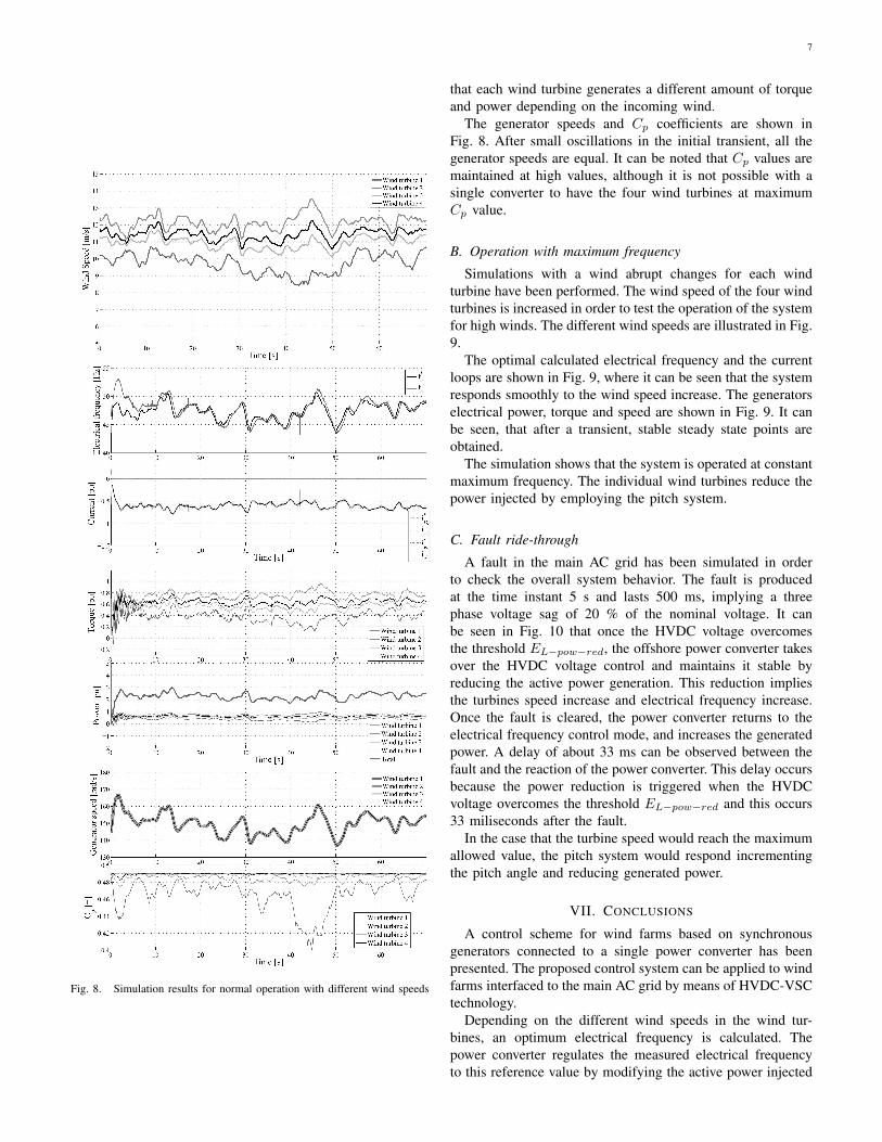
A. Normal operation with different wind speeds
Simulations with four different varying winds for each windturbine have been performed. The different wind speeds areillustrated in Fig. 8. The system has been simulated withdifferent winds for each machine in order to evaluate thesystem performance with a single power converter.
The optimal calculated electrical frequency is shown inFig. 8, where it can be seen that it is changing dependingon the different wind speed measurements. The frequencycontroller regulates smoothly the system to the desired valueby modifying the power converter current i∗sq . The electricalfrequency evolution is slow in order to guarantee systemstability. The power converter current loops are illustrated inFig. 8, a good tracking of both i∗sq and i∗sd can be observed.
The generators electrical power and torque are shown inFig. 8. After an initial transient, both torque and power changeaccording to the overall power converter power. It can be noted
7
Fig. 8. Simulation results for normal operation with different wind speeds
that each wind turbine generates a different amount of torqueand power depending on the incoming wind.
The generator speeds and Cp coefficients are shown inFig. 8. After small oscillations in the initial transient, all thegenerator speeds are equal. It can be noted that Cp values aremaintained at high values, although it is not possible with asingle converter to have the four wind turbines at maximumCp value.
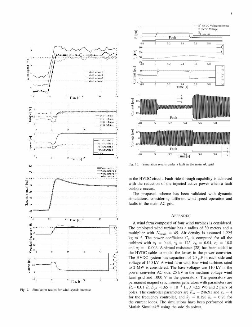
B. Operation with maximum frequency
Simulations with a wind abrupt changes for each windturbine have been performed. The wind speed of the four windturbines is increased in order to test the operation of the systemfor high winds. The different wind speeds are illustrated in Fig.9.
The optimal calculated electrical frequency and the currentloops are shown in Fig. 9, where it can be seen that the systemresponds smoothly to the wind speed increase. The generatorselectrical power, torque and speed are shown in Fig. 9. It canbe seen, that after a transient, stable steady state points areobtained.
The simulation shows that the system is operated at constantmaximum frequency. The individual wind turbines reduce thepower injected by employing the pitch system.
C. Fault ride-through
A fault in the main AC grid has been simulated in orderto check the overall system behavior. The fault is producedat the time instant 5 s and lasts 500 ms, implying a threephase voltage sag of 20 % of the nominal voltage. It canbe seen in Fig. 10 that once the HVDC voltage overcomesthe threshold EL−pow−red, the offshore power converter takesover the HVDC voltage control and maintains it stable byreducing the active power generation. This reduction impliesthe turbines speed increase and electrical frequency increase.Once the fault is cleared, the power converter returns to theelectrical frequency control mode, and increases the generatedpower. A delay of about 33 ms can be observed between thefault and the reaction of the power converter. This delay occursbecause the power reduction is triggered when the HVDCvoltage overcomes the threshold EL−pow−red and this occurs33 miliseconds after the fault.
In the case that the turbine speed would reach the maximumallowed value, the pitch system would respond incrementingthe pitch angle and reducing generated power.
VII. CONCLUSIONS
A control scheme for wind farms based on synchronousgenerators connected to a single power converter has beenpresented. The proposed control system can be applied to windfarms interfaced to the main AC grid by means of HVDC-VSCtechnology.
Depending on the different wind speeds in the wind tur-bines, an optimum electrical frequency is calculated. Thepower converter regulates the measured electrical frequencyto this reference value by modifying the active power injected
8
Fig. 9. Simulation results for wind speeds increase
4.8 5 5.2 5.4 5.6 5.8
1
1.1
E [
pu]
Fault
E* HVDC Voltage referenceE HVDC VoltageE
L−pow−red
4.8 5 5.2 5.4 5.6 5.845
50
55
60
f e [H
z]
fe*
fe
4.8 5 5.2 5.4 5.6 5.8−1.5
−1
−0.5
0
Time [s]
Cur
rent
[pu
]
isq*
isq
isd*
isd
4.8 5 5.2 5.4 5.6 5.8
−1
−0.5
0
0.5
1
Time [s]
Cur
rent
[pu
]
Fault
abc
4.8 5 5.2 5.4 5.6 5.8
−1
−0.5
0
0.5
1
Time [s]
Vol
tage
[pu
]
Fault abc
Fig. 10. Simulation results under a fault in the main AC grid
in the HVDC circuit. Fault ride-through capability is achievedwith the reduction of the injected active power when a faultonshore occurs.
The proposed scheme has been validated with dynamicsimulations, considering different wind speed operation andfaults in the main AC grid.
APPENDIX
A wind farm composed of four wind turbines is considered.The employed wind turbine has a radius of 30 meters and amultiplier with Nmult = 45. Air density is assumed 1.225kg m−3. The power coefficient Cp is computed for all theturbines with c1 = 0.44, c2 = 125, c6 = 6.94, c7 = 16.5and c9 = −0.003. A virtual resistance [28] has been added tothe HVDC cable to model the losses in the power converter.The HVDC system has capacitors of 20 µF in each side andvoltage of 150 kV. A wind farm with four wind turbines ratedto 2 MW is considered. The base voltages are 110 kV in thepower converter AC side, 25 kV in the medium voltage windfarm grid and 1000 V in the generators. The generators arepermanent magnet synchronous generators with parameters areRs= 0.01 Ω, Lqd =1.65 × 10⁻⁴ H, λ =2.5 Wb and 2 pairs ofpoles. The controller parameters are Kn = 246.91 and τn = 4for the frequency controller, and kp = 0.125 ki = 6.25 forthe current loops. The simulations have been performed withMatlab Simulinkr using the ode15s solver.
9
REFERENCES
[1] N. Ullah, K. Bhattacharya, and T. Thiringer, “Wind farms as reactivepower ancillary service providers technical and economic issues,” IEEETransactions on Energy Conversion, vol. 24, pp. 661–672, 2009.
[2] Z. Miao, L. Fan, D. Osborn, and S. Yuvarajan, “Control of dfig-based wind generation to improve interarea oscillation damping,” IEEETransactions on Energy Conversion, vol. 24, pp. 415– 422, 2009.
[3] O. Gomis-Bellmunt, A. Junyent-Ferre, A. Sumper, and J. Bergas-Jane, “Ride-through control of a doubly fed induction generator underunbalanced voltage sags,” IEEE Transactions on Energy Conversion,vol. 23, no. 4, pp. 1036–1045, 2008.
[4] A. Sumper, O. Gomis-Bellmunt, A. Sudria-Andreu, R. Villafafila-Robles, and J. Rull-Duran, “Response of fixed speed wind turbines tosystem frequency disturbances,” IEEE Transaction on Power Systems,vol. 24, pp. 181–192, 2009.
[5] L.-R. Chang-Chien and Y.-C. Yin, “Strategies for operating wind powerin a similar manner of conventional power plant,” IEEE Transactionson Energy Conversion, vol. 24, pp. 926–934, 2009.
[6] N. B. Negra, J. Todorovic, and T. Ackermann, “Loss evaluation ofHVAC and HVDC transmission solutions for large offshore wind farms,”Electric Power Systems Research, vol. 76, no. 11, pp. 916–927, 2006.
[7] J. Arrillaga, High Voltage Direct Current Transmission, 2nd ed. London,U.K.: Institution of Electrical Engineers, 1998.
[8] S. Bozhko, G. Asher, R. Li, J. Clare, and L. Yao, “Large offshore DFIG-based wind farm with line-commutated HVDC connection to the maingrid: Engineering studies,” IEEE Transaction on Energy Conversion,vol. 23, no. 1, pp. 119–127, 2008.
[9] D. Xiang, L. Ran, J. Bumby, P. Tavner, and S. Yang, “Coordinatedcontrol of an HVDC link and doubly fed induction generators in a largeoffshore wind farm,” IEEE Transactions on Power Delivery, vol. 21,no. 1, pp. 463–471, 2006.
[10] T. Ackermann, “Transmission systems for offshore wind farms,” IEEEPower Engineering Review, vol. 22, no. 12, pp. 23–27, Dec. 2002.
[11] L. Xu and B. Andersen, “Grid connection of large offshore wind farmsusing HVDC,” Wind Energy, vol. 9, no. 4, pp. 371–382, 2006.
[12] L. Xu, L. Yao, and C. Sasse, “Grid integration of large DFIG-based windfarms using VSC transmission,” IEEE Transactions on Power Systems,vol. 22, no. 3, pp. 976–984, 2007.
[13] T. Vrionis, X. Koutiva, N. Vovos, and G. Giannakopoulos, “Control ofan HVDC link connecting a wind farm to the grid for fault ride-throughenhancement,” IEEE Transactions on Power Systems, vol. 22, no. 4, pp.2039–2047, 2007.
[14] D. Jovcic, “Offshore wind farm with a series multiterminal CSI HVDC,”Electric Power Systems Research, vol. 78, pp. 747–755, 2008.
[15] D. Jovcic and N. Strachan, “Offshore wind farm with centralised power
conversion and DC interconnection,” IET Generation, Transmission andDistribution, vol. 3, pp. 586–595, 2009.
[16] M. Chinchilla, S. Arnaltes, and J. C. Burgos, “Control of permanent-magnet generators applied to variable-speed wind-energy systems con-nected to the grid,” IEEE Transactions on Energy Conversion, vol. 21,pp. 130–135, 2006.
[17] D. Goodfellow and G. Smith, “Control strategy for variable speed of afixed-pitch wind turbine operating in a wide speed range,” in Proc. of8th BWEA Conference, Cambridge, 1986, pp. 219–228.
[18] R. Pena, J. J.C. Clare, and G. Asher, “Doubly fed induction generatorusing back-to-back PWM converters and its application to variable-speedwind-energy generation,” IEE Proceedings Electric Power Applications,vol. 143, no. 3, pp. 231–241, 1996.
[19] C. Feltes, H. Wrede, F. Koch, and I. Erlich, “Enhanced fault ride-throughmethod for wind farms connected to the grid through VSC-based HVDCtransmission,” IEEE Transactions on Power Systems, vol. 24, pp. 1537– 1546, 2009.
[20] R. L. Hendriks, R. Volzke, and W. L. Kling, “Fault ride-throughstrategies for vsc-connected wind parks,” in EWEC2009 European WindEnergy Conference, Marseille, France, 2009, pp. 1–6.
[21] R. Barthelmie and S. Pryor, “Can satellite sampling of offshore windspeeds realistically represent wind speed distributions?” Journal ofApplied Meteorology, vol. 42, pp. 83–94, 2003.
[22] S. Pryor, M. Nielsen, R. Barthelmie, and J. Mann, “Can satellitesampling of offshore wind speeds realistically represent wind speed dis-tributions? part ii: Quantifying uncertainties associated with distributionfitting methods,” Journal of Applied Meteorology, vol. 43, pp. 739–750,2004.
[23] P. Soerensen, A. D. Hansen, F. Iov, F. Blaabjerg, and M. H. Donovan,“Risoe-r-1464 wind farm models and control strategies,” Risoe, Tech.Rep., 2005.
[24] Z. Lubosny, Wind Turbine Operation in Electric Power Systems.Springer, 2003.
[25] G. Terorde, Electrical Drives and Control Techniques, 1st ed. UitgeverijAcco, 2004.
[26] H. Akagi, Y. Kanazawa, and A. Nabae, “Instantaneous reactive powercompensators comprising switching devices without energy storagecomponents,” IEEE Transaction on Industry Applications, vol. 20, pp.625–631, 1984.
[27] L. Harnefors and H.-P. Nee, “Model-based current control of ac ma-chines using the internal model control method,” IEEE Transactions onIndustry Applications, vol. 34, no. 1, pp. 133–141, Jan.-Feb. 1998.
[28] H. Xie, L. Angquist, and H.-P. Nee, “Design and analysis of a controllerfor a converter interface interconnecting an energy storage with the DClink of a VSC,” IEEE Transactions on Power Systems, vol. 25, pp. 1007–1015, 2010.


![Lecture 7 - Synchronous Generators[1]](https://img.pdfslide.us/doc/110x75/552639fd550346586f8b4b79/lecture-7-synchronous-generators1.jpg)