Embed Size (px)
Citation preview
ControlIT I/O System S900
Digital I/O Modules DO910 and DX910
Manual

I/O System S900 Digital I/O Modules DO910 and DX910
2 3BDD010423R0101

I/O System S900 Digital I/O Modules DO910 and DX910
3BDD010423R0101 3
ControlIT I/O System S900
Digital I/O Modules DO910 and DX910
Manual

I/O System S900 Digital I/O Modules DO910 and DX910
4 3BDD010423R0101
NOTICE The information in this document is subject to change without notice and should not be construed as a commitment by ABB. ABB assumes no responsibility for any errors that may appear in this document.
In no event shall ABB liable for direct, indirect, special, incidental or consequential damages of any nature or kind arising from the use of this document, nor shall ABB be liable for incidental or consequential damages arising from use of any software or hard-ware described in this document.
This document and parts thereof must not be reproduced or copied without written per-mission from ABB, and the contents thereof must not be imparted to a third party nor used for any unauthorized purpose.
The software or hardware described in this document is furnished under a license and may be used, copied, or disclosed only in accordance with the terms of such license.
Copyright © 2001 ABB All rights reserved.
Release: December 2002 Document number: 3BDD010423R0101 Rev. A
CE Marking This product meets the requirements specified in EMC Directive 89/336/EEC and in Low Voltage Directive 73/23/EEC.
TRADEMARKS FieldController is a registered trademark of ABB Automation Products GmbH, Germany
PROFIBUS and PROFIBUS-DP are trademarks of PROFIBUS International (P. I.).
HART is a trademark of the HART Communication Foundation.

I/O System S900 Digital I/O Modules DO910 and DX910
3BDD010423R0101 5
TABLE OF CONTENTS
TABLE OF CONTENTS....................................................................................5
1. About this document..........................................................................7
2. Short description................................................................................8
DO910 8 DX910 8
3. Field-side connection.........................................................................9
Connecting peripheral components...................................................................9 DO910 9 DX910 13
Line monitoring ................................................................................................16 Intrinsically safe connection of hazardous area field devices .........................18
4. PROFIBUS DP communication .......................................................20
Configuration ...................................................................................................20 Parameterization .............................................................................................21
Parameterization in mode 1.................................................................21 Parameterization in mode 2.................................................................22 Debouncing..........................................................................................23 Polarity .................................................................................................24
I/O data ............................................................................................................24 Validity of input data ............................................................................24 Output data ..........................................................................................26 I/O data arrangement on PROFIBUS ..................................................26
Diagnostics ......................................................................................................28 Error reaction...................................................................................................28
Input data (DX910 only).......................................................................28 Output data (DO910 and DX910) ........................................................28

I/O System S900 Digital I/O Modules DO910 and DX910
6 3BDD010423R0101
5. Commissioning.................................................................................29
Standard PROFIBUS master...........................................................................29 DTM 30 Symphony / Melody .........................................................................................30
Input data .............................................................................................30 Output data ..........................................................................................32
AC800F............................................................................................................33 Input data .............................................................................................33 Output data ..........................................................................................35
AC800M...........................................................................................................36 Diagnostics ..........................................................................................36 Measuring value status........................................................................37
I/O System S900 Digital I/O Modules DO910 and DX910
1. About this document
This publication includes Warnings, Cautions and Information issues where appropriate to point out safety-related or other important information. It also includes Tips to point useful hints to the reader. The corresponding symbols should be interpreted as follows:
Warnings indicate the presence of a hazard which could result in personal injury.
Cautions indicate the presence of a hazard which could result in equipment or property damage.
Information alerts the reader to pertinent facts and conditions.
Indicates special conditions for meeting explosion protection requirements.
Although Warning hazards are related to personal injury, and Caution hazards are associated with equipment or property damage, it should be understood that operation of damaged equipment could, under certain operational conditions, result in degraded process performance leading to personal injury or death. Therefore, comply fully with all Warning and Caution notices.
3BDD010423R0101 7
I/O System S900 Digital I/O Modules DO910 and DX910
8 3BDD010423R0101
2. Short description
DO910 The digital output module DO910 is used for activating intrinsically safe valves, relays, or lamps and features 4 channels. The channels are electrically isolated from each other and from the internal bus. Power is supplied via the termination unit of the SI/O system S900, external power supply is not required.
• Output for intrinsically safe valves or lamps • Integrated supply • Short circuit and line break detection • Electrical isolation between output / internal bus / EV • Channel-wise electrical isolation • 4 channels, EEx ia II C
DX910 The digital I/O module DX910 can be configured as input as well as output and, therefore, can be used universally. When used as input, the module is used for evaluating NAMUR proximity switches or mechanical and electronic contacts. Used as output, for example, low power valves can be activated. The module has 8 channels which can be operated as input or output module-wise or in pairs, depending on the parameterization mode.
• Input for NAMUR proximity switches or contacts • Output for intrinsically safe low power valves • Short circuit and line break detection • Electrical isolation between input / internal bus / EV • Inputs and output not electrically isolated • Can be configured as input or output • 8 inputs/outputs, EEx ia II C

I/O System S900 Digital I/O Modules DO910 and DX910
3. Field-side connection
Connecting peripheral components
DO910
Figure 3–1 DO910 Front view and contact assignment
The module is used for connecting valves and relays with current requirements up to approximately 40 mA. All four channels each have two outputs A and B with different voltage limits, which may only be used alternately, not simultaneously.
3BDD010423R0101 9

I/O System S900 Digital I/O Modules DO910 and DX910
Switching performance / output characteristic The following figure shows the output voltage in relation to the output current. Starting at a current of approximately 25 mA, the curves of characteristic A and B are identical. If the operating point of the connected actuator is within the common area, the connection can be established to terminal pair A or B. Observe the different voltage limits!
Only devices with an internal resistance above 270 Ω may be connected.
U [V]
i [mA]
Open Line
Short Circuit5
10
15
20
25
10 20 30 40 50
curve A
curve B
Non permissible area
Normal workingarea
R = 270 Ω
Figure 3-2 Output characteristic
Below a current of approximately 1 mA a wire-break is reported. Wire-break monitoring can be deactivated.
If the voltage across the load falls below 5 V, a short-circuit is reported. Short-circuit monitoring can be deactivated.
Selection of suitable valves / relays • For Umax < 27 V connect to terminal pair B, otherwise to A • Ri > 1500 Ω* • UN < 26 V *Although it is possible to connect devices with an internal resistance as low as 270 Ω, this will reduce the number of plug-in modules of the S900 station.
10 3BDD010423R0101

I/O System S900 Digital I/O Modules DO910 and DX910
The coil resistance of valves and relays decreases with the temperature. For components with low internal resistance (< 400 Ω), the resistance at minimum operating temperature must be inquired at the manufacturer.
Example 1:
The following information is found on the rating plate of a valve:
UN = 7 .. 34 V IN = 4.3 .. 25 mA PN = 30 .. 850 mW
The internal resistance is approximately 1.5 kΩ. In switched-on condition this results in an operating point on curve A at approximately 21 V respectively 16 V on curve B. The valve can be connected to both terminal pairs, as the maximum permissible nominal operating voltage is 34 V. When connecting to B, the output is already within the voltage limit. This does not influence the power dissipation of the module.
• U [V]
i [mA]
5
10
15
20
25
10 20 30 40 50
curve A
curve B
load = 1.5 kΩ
Figure 3-3 Example: Determining the operating point of a valve
3BDD010423R0101 11

I/O System S900 Digital I/O Modules DO910 and DX910
Example 2:
The following information is found on the rating plate of a relay:
UN = 12 V (+/- 10%) IN = 40 mA
The internal resistance is 300 Ω. In switched-on condition this will result in an operating point of approximately 12 V and 40 mA. This operating point exactly matches the rated data of the relay. Due to the relatively lower resistance and the inherent high power consumption (in relation to the valve in example 1), the number of plug-in modules in an S900 station is reduced (for details regarding the maximum number of I/O modules refer to the mounting and installation instruction of the S900 I/O system).
U [V]
i [mA]
5
10
15
20
25
10 20 30 40 50
curve A
curve B
load = 1.5 kΩ
Figure 3-4 Example: Determining the operating point of a relay
12 3BDD010423R0101

I/O System S900 Digital I/O Modules DO910 and DX910
DX910
Figure 3–5 DX910 Front view and contact assignment
The module is used for connecting contactless sensors or initiators according to IEC60947 (Low-voltage switchgear and control gear, Part 5-6:. Control circuit devices and switching elements – DC interface for proximity sensors and switching amplifiers (NAMUR)) or DIN60947, respectively. Alternatively potential-free contacts can be connected and evaluated by the module. External power supply is not required, as it is provided by the module itself. When using the module as output, intrinsically safe low power valves or optocouplers can be used, for example.
Observe the common electrical interconnection of the channels. This means that only potential-free sensors, contacts, and valves can be connected.
3BDD010423R0101 13
I/O System S900 Digital I/O Modules DO910 and DX910
The technical data in the data sheet (catalog) only applies to channels without load respectively for situations where all channels are loaded within the valid range. Short-circuits an all other channels results in a load curve on the remaining channel that is approximately 40% lower.
Switching performance (input) The following figure shows the load curve of the module when using it as an input. Connected sensors according to the standard mentioned above will always be within the ON or OFF ranges, their switching point is sufficiently far from the module's switching threshold, so that safe detection is always guaranteed. If other sensors are to be connected, make sure that the characteristic curve is within the ON or OFF ranges. For a simple contact this is not the case, as the load resistance is either infinite (switch open) or close to 0 (switch closed). When deactivating the line-break and short-circuit monitoring,
• the short-circuit range goes to the ON condition (“1”), • the line-break range goes to the OFF condition (“0”).
Connecting a switching contact deactivates the line-break and short-circuit monitoring. In addition, each input can be debounced.
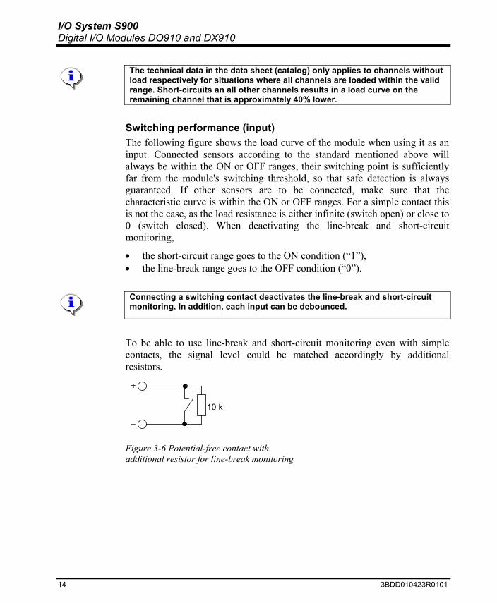
To be able to use line-break and short-circuit monitoring even with simple contacts, the signal level could be matched accordingly by additional resistors.
+
–
10 k
Figure 3-6 Potential-free contact with additional resistor for line-break monitoring
14 3BDD010423R0101

I/O System S900 Digital I/O Modules DO910 and DX910
1 k+
–
Figure 3-7 Potential-free contact with additional resistor for short-circuit detection
1 k+
–
10 k
Figure 3-8 Potential-free contact with both resistors for line-break and short-circuit monitoring
U [V]
i [mA]
off‘0’
on‘1’
Open Line
switchingpoint
Short Circuit
Uno Load
line breakdetection
short circuitcurrent
short circuitdetection
Figure 3-9 Input load curve
Switching performance (output) The no-load voltage is approximately 4.5 V in the OFF condition (“0”), however with very high internal resistance. The resistance of a connected load
3BDD010423R0101 15

I/O System S900 Digital I/O Modules DO910 and DX910
(e. g. a low power valve) causes the voltage to break down to a few mV. Therefore, the following load curve only describes the ON condition (“1”).
U [V]
i [mA]
on‘1’
Open Line
Short Circuit
Uno Load
line breakdetection
short circuitcurrent
short circuitdetection
Figure 3-10 Output load curve
Selection criteria for loads with ohmic resistance (e. g. relay coil):
• 1100 Ω < R < 40 kΩ • UN min < 8 V • IN min < 4 mA • PN min < 17 mW
Selection criteria for non-linear loads (e. g. optocouplers):
• Determine the input characteristic curve of the load. • The intersection of the input curve and output load curve must be within
the permissible range (ON). • The intersection must not be less than the nominal voltage of the load. • The intersection must not be less than the nominal current of the load.
Line monitoring The modules described monitor the lines to the connected actuator / sensor. Line monitoring can be deactivated.
16 3BDD010423R0101

I/O System S900 Digital I/O Modules DO910 and DX910
For output channels, line monitoring is only active when the channel outputs “1”.
Table 3-1 Conditions valid for the detection of line-break and short-circuit
DO910 DX910 Line-break i < 0.5 mA i < 0.12..0.2 mA Short-circuit R < 176 Ω* R < 300..350
*) The voltage of the channel concerned (= output channel) is pulsed at approximately 1 kHz to prevent overloading the module by the short-circuit current. With software version 1.10 of the module, pulsing is only done when short-circuit monitoring is activated. From software version 1.41 onwards, this function is independent from monitoring.
3BDD010423R0101 17

I/O System S900 Digital I/O Modules DO910 and DX910
Intrinsically safe connection of hazardous area field devices When using the S-version of S900 Digital I/O modules together with field devices protected for use in potentially explosive atmospheres, the rules for interconnecting current circuits regarding intrinsically safe electrical systems “I” must be observed. Safety measures for the function itself are required, too, but not sufficient alone.
The connection of an “S” module to an explosion-protected field device requires the consideration of interconnections according to EN50039. To be compared are the respective EC Type Examination Certificates; only this data is relevant.
The following information concerns the most important parameters, however, only the standard mentioned above is binding and comprehensive.
The following device data must be compared:
UO: maximum output voltage IO: maximum output current PO: maximum output power LO: maximum external inductance CO: maximum external capacitance UI: maximum input voltage II: maximum input current PI: maximum input power LI: maximum internal inductance CI: maximum internal capacitance CC: cable capacitance LC: cable inductance
18 3BDD010423R0101

I/O System S900 Digital I/O Modules DO910 and DX910
3BDD010423R0101 19
Table 3-2 Comparison of data relevant for explosion protection
DO910S and DX910S Module data Field device
data Comment
Uo ≤ UI Io ≤ II Po ≤ PI
The maximum values for voltage, current, and power of the module must be smaller than the input values of the field device.
Lo ≥ LI + Lc
Co ≥ CI + Cc
The sum of the inductance respectively capacitance of the field device and the line must be smaller than the permissible external values of the module. The internal module values are already taken into account for LO and CO.
Not all parameters are listed in all cases. Normally, only those values must be considered that are contained in the EC Type Examination Certificate. All parameters listed above must be taken from the corresponding EC Type Examination Certificates according to the category (ia or ib) and gas group (IIC or IIB) used.

I/O System S900 Digital I/O Modules DO910 and DX910
4. PROFIBUS DP communication
Configuration
Definition In this context, configuration means arranging the individual I/O modules of a modular slave and, thus, making changes that have an effect on the structure of the I/O data telegrams.
Changing the configuration on a PROFIBUS means terminating cyclic data exchange and re-assigning the I/Os in the PROFIBUS master. Additional features like HCIR (Hot Configuration In Run) allow for a smooth change-over, which seems to be performed 'online' from the user's point of view. S900 fully supports HCIR. Of course, HCIR must also be supported by the PROFIBUS master, as it is done, for example, for the ABB process control systems Symphony / Melody. By description of the required parameters in the GSD file (device data file), HCIR can be executed by any PROFIBUS master supporting online re-parameterization (see below). Since each of the modules described can supply a different number of secondary HART variables (up to 8, depending on the parameterization mode), PROFIBUS requires the formation of individual subtypes or variants here. Each variant of a type (in this context, type corresponds to the catalog number) supplies a different amount of I/O data.
Table 4-1 Module variant overview
Type Variant Description DO910 DO4 Binary output, 4 x 1 channels (valve control block)
DIO8 Binary input/output, 1 x 8 channels DIO8 S Binary input/output, 1 x 8 channels, incl. status DIO8 8I Binary input, 1 x 8 channels
DX910
DIO8 8I S Binary input/, 1 x 8 channels, incl. status
20 3BDD010423R0101

I/O System S900 Digital I/O Modules DO910 and DX910
Parameterization
Definition In this context, parameterization means defining the properties of already configured modules.
Since parameter changes do not influence the I/O data structure, the system does not necessarily need to be recompiled after making changes in the master. S900 allows to transmit (and receive) a parameter telegram without interrupting cyclic data exchange. The ABB process control systems, e.g. AC800F, together with S900 support this kind of online-re-parameterization.
Parameterization in mode 1 Principally this is a module-wise parameterization, i. e. all channels of a module operate with identical parameters, e. g. “Short-circuit monitoring ON”. When parameterizing the channels as input or output (DX910) this rule is disregarded, in order to increase flexibility. The following table describes the individual parameters for the selectable variants.
Table 4-2 Parameters in parameterization mode 1
Parameter Type (variant) Setting Description Short-circuit monitoring
DO910 DX910
ON / OFF Switches short-circuit monitoring ON or OFF for all module channels. When a short circuit is detected on one channel, the respective input value (for digital input) is marked as invalid, and a channel diagnosis is transmitted.
Line-break monitoring
DO910 DX910
ON / OFF Switches line-break monitoring ON or OFF for all module channels. When a line-break is detected on one channel, the respective input value (for digital input) is marked as invalid, and a channel diagnosis is transmitted.
min In case of error the channel assumes the value “0”.
max In case of error the channel assumes the value “1”.
Substitute value DO910 DX910
last valid value
In case of error the channel assumes the last detected valid value.
3BDD010423R0101 21

I/O System S900 Digital I/O Modules DO910 and DX910
Parameter Type (variant) Setting Description OFF All channels operate with the
lowest possible filter setting / attenuation.
Debouncing DX910
50 ms All channels are debounced with a filter time of 50 ms
normal All channels operate with normal polarity.
Polarity DX910 DO910
inverted All channels are inverted. 8 inputs All 8 module channels are used as
inputs. 4 inputs / 4 outputs
4 module channels (1 to 4) are used as inputs, 4 module channels (5 to 8) as outputs.
5 inputs / 3 outputs
5 module channels (1 to 5) are used as inputs, 3 module channels (6 to 8) as outputs.
Effective direction DX910 (DIO8) DX910 (DIO8 S)
8 outputs All 8 module channels are used as outputs.
Unused channels can also be deactivated in mode 1 through the use of CI920 variant CIPB-D.
Parameterization in mode 2 Principally this is a channel-wise parameterization, i. e. the individual channels can be parameterized separately. However, for the DX910 module the multitude of parameters exceeds the PROFIBUS capabilities, so that two adjacent channels will also be used in pairs. The following table describes the individual parameters for the selectable variants.
Table 4-3 Parameters in parameterization mode 2
Parameter Type (variant) Setting Description Short circuit monitoring DO910
DX910 ON / OFF Switches short-circuit monitoring
ON or OFF for this channel resp. channel pair. When a short circuit is detected on one channel, the respective input value (for digital input) is marked as invalid, and a channel diagnosis is transmitted.
Line-break monitoring DO910 DX910
ON / OFF Switches line-break monitoring ON or OFF for this channel resp. channel pair. When a line-break is
22 3BDD010423R0101

I/O System S900 Digital I/O Modules DO910 and DX910
Parameter Type (variant) Setting Description detected on one channel, the respective input value (for digital input) is marked as invalid, and a channel diagnosis is transmitted.
min In case of error the channel assumes the value “0”.
max In case of error the channel assumes the value “1”.
Substitute value* DO910 DX910
last valid value In case of error the channel assumes the last detected valid value.
off This channel (channel pair) operates with the smallest possible debouncing time.
10 ms 20 ms
Debouncing DX910
50 ms
This channel (channel pair) is debounced with the filter time set.
normal This channel (channel pair) operates with normal polarity.
Polarity DX910 DO910
inverted This channel (channel pair) is inverted.
input This channel pair operates as input.
Effective direction DX910 (DIO8) DX910 (DIO8 S)
output This channel pair operates as output.
active This channel is used. Channel 1 to 8 DX910 not active This channel is not used.
*) Although the setting is for channel pairs for the DX910, only the channel with the error assumes the substitute value.
In mode 2, unused channels are deactivated by parameters “Channel 1 to 8”.
Debouncing This functions is used to filter out interference signals (short voltage peaks / drops) and for safe reading of bouncing contacts (e. g. relays). The read value is only transmitted to the control system, when the signal level is stable over the parameterized time. A too high debouncing time results in delayed forwarding of the state.
3BDD010423R0101 23

I/O System S900 Digital I/O Modules DO910 and DX910
24 3BDD010423R0101
Polarity The polarity parameter facilitates designing the control system application independently from the I/O connection. The control system application does not have to deal with the inverse logic of some sensors / actuators. The desired behavior is set via the user parameters of the S900. Note that the inversion in case of output data also influences the substitute values.
Input data
Table 4-4 Logic of digital input values
PROFIBUS input data normal inverted
Terminal = “0” “0” '”1” Terminal = “1” “1” “0” Substitute value = min (for error) “0” “0” Substitute value = max (for error) '”1” “1”
Output channels
Table 4-5 Logic of digital output values
Field terminal state normal inverted
DP Master output data = “0” “0” '”1” DP Master output data = “1” '”1” “0” Substitute value = min (for error) “0” '”1” Substitute value = max (for error) '”1” “0”
I/O data
Validity of input data S900 provides optional status information for every analog or digital input value. The status indicates the validity of the measuring value, independent of the selected substitution value strategy. In the application of the process control system an individual substitution value strategy can be used, with the status bit set. Contrary to the PROFIBUS channel diagnosis the measured value status provides for real-time transmission and, thus, data consistency. As a rule, a transmitted substitution value or last valid value always results in

I/O System S900 Digital I/O Modules DO910 and DX910
3BDD010423R0101 25
a set status bit, provided that status information transmission has not been disabled by setting the bus coupler parameters accordingly. The ABB process control systems, e.g. Symphony / Melody, always use measured values with status information. This ensures consistent measuring value marking throughout the entire measuring chain. Any channel error, module error or disturbance of PROFIBUS communication will cause an invalid input value. In this case, the PROFIBUS master automatically sets the status bit to the “invalid” state, i. e. to “1”. For other process control systems the status information can be accessed like a digital input. However, the user then has to process it “manually” in the application.
Table 4-6 Generation of measuring value status for input data
Cause Status bit is set by Condition Channel error Line-break Short-circuit Overflow Underflow
S900 I/O module Respective monitoring function is active
Module error S900 bus coupler CI920 Configuration error Invalid module Module missing
S900 bus coupler CI920
Bus coupler CI920 defective
PROFIBUS master The process control system (e. g. ABB CMC60) either uses measured values with status information, or the substitution value can be set in the master for the status signal (e. g. ABB AC800F)
PROFIBUS communication interrupted
PROFIBUS master The process control system (e. g. ABB CMC60) either uses measured values with status information, or the substitution value can be set in the master for the status signal (e. g. ABB AC800F)

I/O System S900 Digital I/O Modules DO910 and DX910
Output data For output data, no channel status (status bit) is supplied. Nevertheless, output channel also have a parameterized substitute value strategy. All output channels of a module assume a substitution value, when
• the PROFIBUS Master transmits the “CLEAR” command. • the PROFIBUS Master transmits the “LEAVE_MASTER” command. • the PROFIBUS Master fails (with PROFIBUS Watchdog switched ON). • the PROFIBUS connection fails (with PROFIBUS Watchdog switched
ON). • the S900 bus coupler CI920 fails.
I/O data arrangement on PROFIBUS The S900 bus coupler CI920 converts the data format used on the internal bus to the standardized PROFIBUS data format.
DO910 (DO4)
Table 4-7 DO910 output data
Output Byte Bit 7..4 3 2 1 0 0 Channel not connected 4 3 2 1
DX910 (DIO8)
Table 4-8 DX910 I/O data (without status)
Input Byte Bit 7 6 5 4 3 2 1 0 0 Channel 8 7 6 5 4 3 2 1 Output 0 Channel 8 7 6 5 4 3 2 1
The module has 8 channels with effective direction (input or output) to be set via parameters. A channel can only be used exclusively for input or output.
In the following example channels 1 to 4 are to be used for input, channels 5 to 8 for output:
26 3BDD010423R0101

I/O System S900 Digital I/O Modules DO910 and DX910
Table 4-9 DX910 I/O data example
Input Byte Bit 7 6 5 4 3 2 1 0 0 Channel X X X X 4 3 2 1 Output 0 Channel 8 7 6 5 X X X X
X These bits must not be used resp. will be ignored.
DX910 (DIO8 S)
Table 4-10 DX910 I/O data (incl. status)
Input Byte Bit 7 6 5 4 3 2 1 0 0 Channel 8 7 6 5 4 3 2 1 1 Status 8 7 6 5 4 3 2 1 Output 0 Channel 8 7 6 5 4 3 2 1
The module has 8 channels with effective direction (input or output) to be set via parameters. A channel can only be used exclusively for input or output. The status bit is only defined when used as input channel.
In the following example channels 1 to 4 are to be used for input, channels 5 to 8 for output:
Table 4-11 DX910 I/O data example (incl. status)
Input Byte Bit 7 6 5 4 3 2 1 0 0 Channel X X X X 4 3 2 1 1 Status X X X X 4 3 2 1 Output 0 Channel 8 7 6 5 X X X X
X These bits must not be used resp. will be ignored.
DX910 (DIO8 8I)
Table 4-12 DX910 input data (inputs only)
Input Byte Bit 7 6 5 4 3 2 1 0 0 Channel 8 7 6 5 4 3 2 1
3BDD010423R0101 27

I/O System S900 Digital I/O Modules DO910 and DX910
28 3BDD010423R0101
DX910 (DIO8 8I S)
Table 4-13 DX910 input data (inputs only, incl. status)
Input Byte Bit 7 6 5 4 3 2 1 0 0 Channel 8 7 6 5 4 3 2 1 1 Status 8 7 6 5 4 3 2 1
Diagnostics The module performs diagnoses in accordance with the PROFIBU standard and provides channel-related error messages. The coding complies with the PROFIBUS standard as well and is beyond the scope of this document. The assignment between the error code and the text is also standardized.
Table 4-14 Diagnostic messages
Line-break One of the connection lines is broken. Short-circuit The connection lines are short-circuited.
Error reaction
Input data (DX910 only) The reaction on errors is defined by setting the “Substitution value strategy” parameter. When setting this parameter to “min. value” the value “0” is transmitted as the input. In addition – if the corresponding module variant is selected – the status bit is set. When selecting “max. value”, the value “1” is transmitted as the input value, and the respective status bit is set. In addition, the status bit is set. Selecting “last valid value” will freeze and maintain the last valid measured value.
Output data (DO910 and DX910) The reaction on errors is defined by setting the “Substitution value strategy” parameter. When setting this parameter to “min. value” the channel assumes the value “0”. When setting this parameter to “max. value” the channel assumes the value “1”. Selecting “last valid value” will freeze and maintain the last valid output value.

I/O System S900 Digital I/O Modules DO910 and DX910
5. Commissioning
Standard PROFIBUS master The language and the parameterization mode are set by loading the respective GSD (device data) file. The following GSD files are available for S900:
• ABB_04D2.GSD Parameterization mode 2, English • ABB_04D2.GSG Parameterization mode 2, German • ABB104D2.GSD Parameterization mode 1, English • ABB104D2.GSG Parameterization mode 1, German
Parameterization mode 1 is designed for simple or older master systems. With this file the master can be parameterized quickly and easily without the need to support plain text. The desired parameter set can be selected from a list, and the respective ID is entered as a module parameter.
Parameterization mode 2 is best suited for advanced master systems and allows for extensive, detailed parameterization.
The performance specifications, operating data, diagnostic functions and cyclic data quality are identical for the module in both parameterization modes.
After having configured the module, you usually set the module parameters. Linking the I/O data to the application / the program is system-specific. Byte and word access are possible to load all module channels simultaneously. The distribution into channels must be performed within the application. As an alternative, bit-wise access to the I/O data is possible.
3BDD010423R0101 29

I/O System S900 Digital I/O Modules DO910 and DX910
DTM Using the DTM simplifies the parameterization / configuration procedure. No manual allocation of the I/O data (mapping) is required. The process control system must be provided with an interface in accordance with the FDT specification to permit proper usage of the DTM. At present, DTM Version 1.x is available for S900. It supports the FDT specification 0.98 and allows for parameterization in mode 1. In the near future Version 2.x of the S900 will be available, which allows for parameterization in mode 2 and supports FDT specification 1.2. Refer to the S900 manual for details about how to use the DTM. The DTM describes the I/O data according to the following fixed scheme:
Mxx_Chyy
ChannelSlot
Symphony / Melody S900 is integrated in the Symphony / Melody system with the DTM. Upon configuration of the module and closing of the DTM the I/O data are available for channel assignment, sorted by channels.
Input data The input data is accessed via the DIDPB function block.
30 3BDD010423R0101

I/O System S900 Digital I/O Modules DO910 and DX910
Figure 5-1 Function block selection
Select the variant “DIDPB B0 Boolean” via the context menu.
Figure 5-2 Variant selection
No other settings are required for this function block.
3BDD010423R0101 31

I/O System S900 Digital I/O Modules DO910 and DX910
Output data The output data is accessed via the DODPB function block.
Figure 5-3 Function block selection
Select the variant “DODPB B0 Boolean” via the context menu.
Figure 5-4 Variant selection
No other settings are required for this function block.
32 3BDD010423R0101
I/O System S900 Digital I/O Modules DO910 and DX910
AC800F AC800F with Control Builder F permits to integrate S900 by
• importing the GSD file • using the DTM • using templates The import of the GSD file for a remote I/O with complex I/O data structures and parameters is quite complicated for S900 and can only be performed by an experienced user. Especially the I/O assignment is time-consuming.
Up to Revision 6.2 the DTMs are not fully supported. There are certain limitations concerning the HART-compatible analog modules (AI930, AI931, AO930). Moreover, no PROFIBUS diagnostic data can be displayed in the hardware tree view.
The limitations described above can be avoided by using the device templates to integrate the S900. A template is a “pre-configured” module with the I/O assignment already made. Please refer to the Control Builder F documentation for details about how to install the templates and the respective sources of supply.
Input data All channels are available as Boolean variables in the I/O editor. In the application, the status bit is processed as a separate binary input signal.
The entries in the I/O editor only take the configuration data of the selected mode into consideration. Since the effective direction of the DX910 channels are predefined via parameters, input variables will also be created for the output channels. These must not be used by the application.
3BDD010423R0101 33

I/O System S900 Digital I/O Modules DO910 and DX910
DX910 (DIO8, DIO8 8I)
Table 5-5 DX910 I/O assignment (input data without status)
DX910 (DIO8 S, DIO8 8I S)
Table 5-6 DX910 I/O assignment (input data incl. status)
34 3BDD010423R0101

I/O System S900 Digital I/O Modules DO910 and DX910
Output data All channels are available as Boolean variables in the I/O editor.
DO910
Figure 5-7 DO910 I/O assignment
DX910 (DIO8, DIO8 S)
Figure 5-8 DX910 I/O assignment (output data)
3BDD010423R0101 35

I/O System S900 Digital I/O Modules DO910 and DX910
AC800M The connection to AC800M resp. Control Builder M is carried out via hardware definition files (HWD). After inserting the module, the channel assignment is performed via the “Connections” dialog box. The table (see below) lists all I/O variables. The inputs and outputs are linked as individual bits (Boolean) or used as byte. Simultaneous use is possible for input data; output data can only be used exclusively.
Figure 5-9 DX910 (DIO 8) I/O data
Diagnostics AC800M does not process standard PROFIBUS diagnostic data. However, status information can be read and used to determine the state of individual channels. An alternative is the use of SMART VISION as PROFIBUS Class 2 Master.
36 3BDD010423R0101

I/O System S900 Digital I/O Modules DO910 and DX910
3BDD010423R0101 37
Measuring value status In S900, output data principally does not have any channel status. Although input data is transmitted to the PROFIBUS Master with status, the status must be processed in the application in AC800M as a normal binary input signal.

I/O System S900 Digital I/O Modules DO910 and DX910
38 3BDD010423R0101
Printed in Germany
Copyright © 2002 by ABB. All Rights Reserved
Registered Trademark of ABB.
Trademark of ABB.
http://www.abb.com/
ABB Automation Products GmbH
Borsigstrasse 2, D-63755 Alzenau
Phone +49(0)6023 92-0, Fax +49(0)6023 92-3430