Embed Size (px)
Citation preview
EN
GLIS
H
UNI EN ISO 9001 - 9190.ETAD
EN
GLIS
H
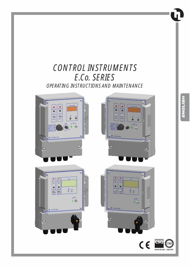
CONTROL INSTRUMENTSE.Co. SERIES
OPERATING INSTRUCTIONS AND MAINTENANCE
TECHNICAL ASSISTANCE AND SALES OFFICES
Via. Catania, 400040 Pavona di Albano Laziale (RM)ITALYTel. +39 06 93 49 891Fax +39 06 93 43 924
North AmericaETATRON DS Inc#203, 17665-66A ave, Surrey BCCANADA V3S 2A7Tel. +1 604 574 1401 Fax +1 604 677 6140www.etatron.com [email protected]
METERING PUMPS
• 23 •
INDEX
1.2 - SHIPPING AND TRANSPORTING THE INSTRUMENT 241.3 - PROPER USE OF THE CONTROLLER 24
2.1 - FASTENING POINTS VIEW 25
4.0 - TROUBLE SHOOTING COMMON TO E.Co. SERIES 27
1.0 - HINTS AND WARNING 24
3.0 - TECHNICAL CHARACTERISTIC 26
1.1 - WARNING 24
2.0 - OVERALL DIMENSIONS 25
1.4 - RISKS 24
5.0 - CONTROL INSTRUMENT E.Co. pH SERIES 29
5.8 - ELECTRODE HOLDERS 32
5.4 - CALIBRATION 315.5 - ELECTRODE TEST 31
5.1 - E.Co. pH INSTALLATION 305.2 - INSTRUMENT OUTPUTS 30
5.6 - ELECTRODE CLEANING AND MAINTENANCE 32
5.3 - CONTROL PANEL E.Co. pH DESCRIPTION 31
5.7 - RECONDITIONING 32
EN
GLIS
H
1.0 - HINTS AND WARNINGS
Please read the warning notices given in this section very carefully, because they provide important informationregarding safety in installation, use and maintenance of the controller.• Keep this manual in a safe place, so that it will always be available for further consultation.• The pump complies with EEC directives No.89/336 regarding "electromagnetic compatibility" and No.73/23
regarding "low voltages", as also the subsequent modification No.93/68.
N.B. The controller has been constructed in accordance with best practice. Both its life and it electrical andmechanical reliability will be enhanced if it is correctly used and subjected to regular maintenance.
Any intervention or repair to the internal parts of the controller must be carried out by qualified and authorizedpersonnel. The manufacturers decline all responsibility for the consequences of failure to respect this rule.
GUARANTEE: 1 year. Improper use of the equipment invalidates the above guarantee. The guarantee isexfactory or authorized distributors.
1.2 - SHIPPING AND TRANSPORTING THE PUMPThe controller should always be moved in a vertical (and never in a horizontal) position. No matter what the meansof transport employed, delivery of the controller, even when free to the purchaser's or the addressee's domicile, isalways at the purchaser's risk. Claims for any missing materials must be made within 10 (ten) days of arrival,while claims for defective materials will be considered up to the 30th (thirtieth) day following receipt. Return ofequipments or other materials to us or the authorized distributor must be agreed beforehand with the responsiblepersonnel.
1.1 - WARNING
• E.Co. series are intended to be used exclusively for measuring and controlling the pH value (E.Co. pH), theredox potential of a liquid (E.Co. Rx), the chlorine percentage (E.Co. Cl) in a plant and the conducibility value(E.Co.CD). The controller should not therefore be used for applications that were not allowed for in its design.In case of doubt, please contact our offices for further information about the characteristics of the controllerand its proper use.
1.4 - RISKS• After unpacking the controller, make sure it is completely sound. In case of doubt, do not use it and con-
tact qualified personnel. The packing materials (especially bags made of plastics, polystyrene, etc.) shouldbe kept out of the reach of children: they constitute potential sources of danger.
• Before you connect the controller, make sure that the voltage ratings, etc., correspond to your particular powersupply. You will find these values on the rating plate attached to the instrument.
• The electrical installation to which the controller is connected must comply with the standards and good prac-tice rule in force in the country under consideration.
• Use of electrical equipment always implies observance of some basic rules: In particular:1 - do not touch the equipment with wet or damp hands or feet;2 - do not operate the controller with bare feet (Example: swimming pool equipment);3 - do not leave the equipment exposed to the action of the atmospheric agents;4 - do not allow the controller to be used by children or unskilled individuals without supervision;• In case of breakdown or improper functioning, switch off, but do not touch. Contact our technical assistance
for any necessary repairs and insist on the use of original spares. Failure to respect this condition could renderthe equipment unsafe for use.
• When you decide to make no further use of an installed instrument, make sure to disconnect it from thepower supply.
Before carrying out any service on the item, check:1. Disconnect the pins from the mains or by means of a two poles switch with 3 mm minimum distance
between the contacts. (Fig. 4).
• 24 •
1.3 - PROPER USE OF THE CONTROLLER
• 25 •
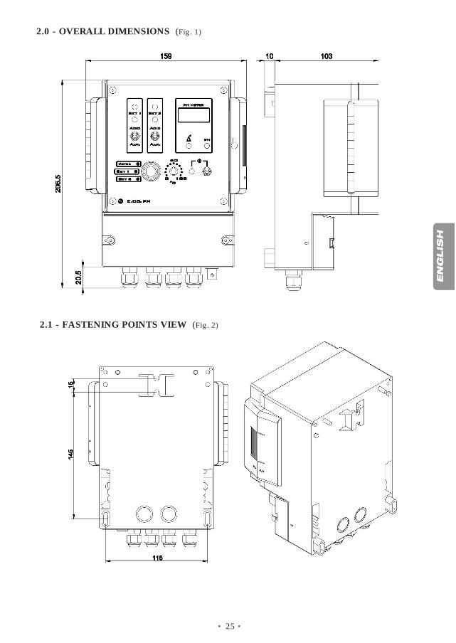
2.1 - FASTENING POINTS VIEW (Fig. 2)
2.0 - OVERALL DIMENSIONS (Fig. 1)
EN
GLIS
H
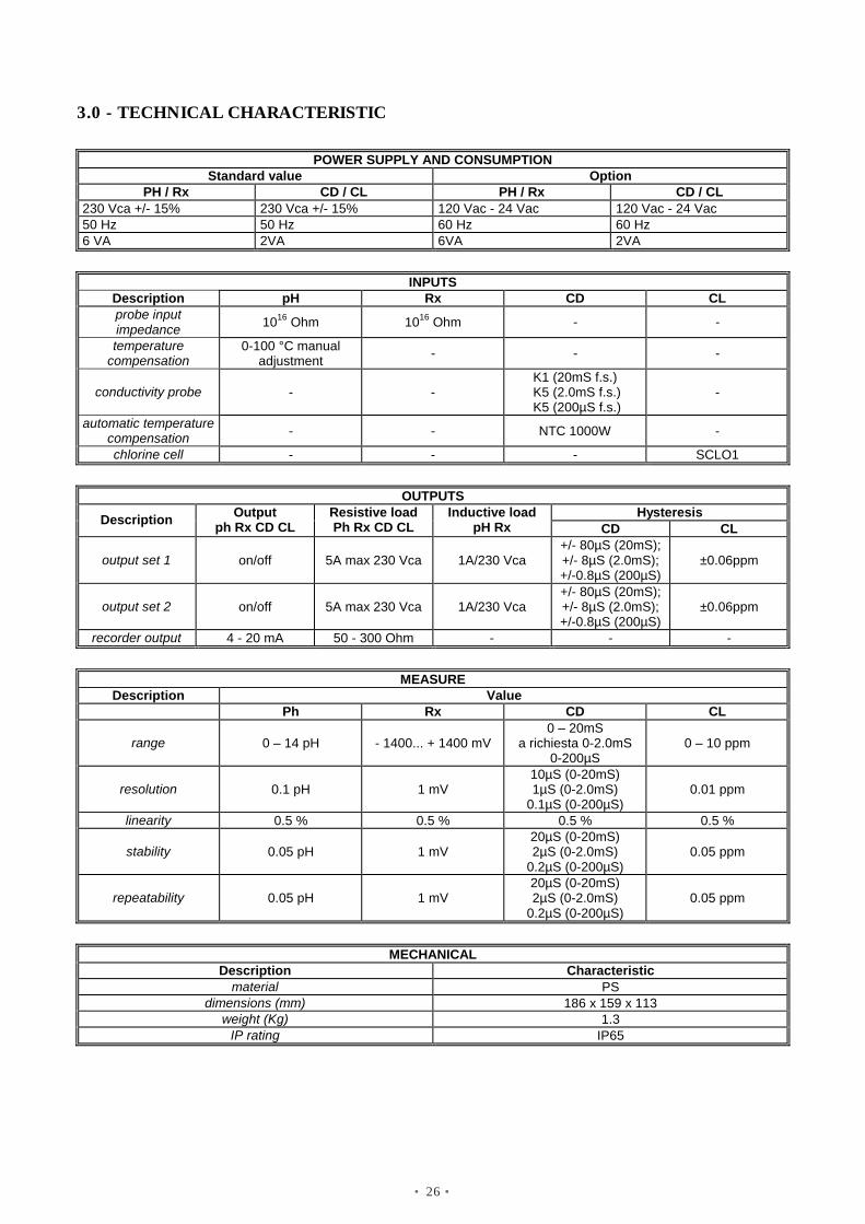
3.0 - TECHNICAL CHARACTERISTIC
POWER SUPPLY AND CONSUMPTION Standard value Option
PH / Rx CD / CL PH / Rx CD / CL 230 Vca +/- 15% 230 Vca +/- 15% 120 Vac - 24 Vac 120 Vac - 24 Vac 50 Hz 50 Hz 60 Hz 60 Hz 6 VA 2VA 6VA 2VA
INPUTS
Description pH Rx CD CL probe input impedance 1016 Ohm 1016 Ohm - -
temperature compensation
0-100 °C manual adjustment - - -
conductivity probe - - K1 (20mS f.s.)
K5 (2.0mS f.s.) K5 (200µS f.s.)
-
automatic temperature compensation - - NTC 1000W -
chlorine cell - - - SCLO1
OUTPUTS Hysteresis Description Output
ph Rx CD CL Resistive load Ph Rx CD CL
Inductive load pH Rx CD CL
output set 1 on/off 5A max 230 Vca 1A/230 Vca +/- 80µS (20mS); +/- 8µS (2.0mS); +/-0.8µS (200µS)
±0.06ppm
output set 2 on/off 5A max 230 Vca 1A/230 Vca +/- 80µS (20mS); +/- 8µS (2.0mS); +/-0.8µS (200µS)
±0.06ppm
recorder output 4 - 20 mA 50 - 300 Ohm - - -
MEASURE Description Value
Ph Rx CD CL
range 0 – 14 pH - 1400... + 1400 mV 0 – 20mS
a richiesta 0-2.0mS 0-200µS
0 – 10 ppm
resolution 0.1 pH 1 mV 10µS (0-20mS) 1µS (0-2.0mS)
0.1µS (0-200µS) 0.01 ppm
linearity 0.5 % 0.5 % 0.5 % 0.5 %
stability 0.05 pH 1 mV 20µS (0-20mS) 2µS (0-2.0mS)
0.2µS (0-200µS) 0.05 ppm
repeatability 0.05 pH 1 mV 20µS (0-20mS) 2µS (0-2.0mS)
0.2µS (0-200µS) 0.05 ppm
MECHANICAL
Description Characteristic material PS
dimensions (mm) 186 x 159 x 113 weight (Kg) 1.3
IP rating IP65
• 26 •
• 27 •
4.0 - TROUBLE SHOOTING COMMON TO E.Co. SERIES
❶ - THE CONTROLLER DOES NOT START
a. Check the connections to the power supply
b. Make sure that the "Oxid/Red" switch is in the right position, i.e. that it concords with the required dosing.
❷ THE CONTROLLER DOES NOT MEASURE CORRECTLY
¸ THE CONTROLLER FAILS TO SWITCH ON THE AUXILIARY EQUIPMENT
Make sure that the controller is completely disconnected from the power supply before undertaking any kindof repair.
b. Check that the fuses are intact (only if external)
a. Make sure that the "set point" has been correctly set
b. Check the efficacy of the electrode
a. Check the calibration of the instrument
EN
GLIS
H
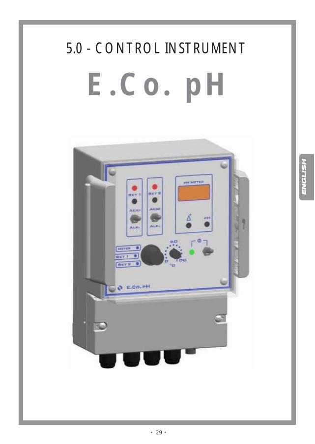
5.0 - CONTROL INSTRUMENT
E.Co. pH
• 29 •
EN
GLIS
H
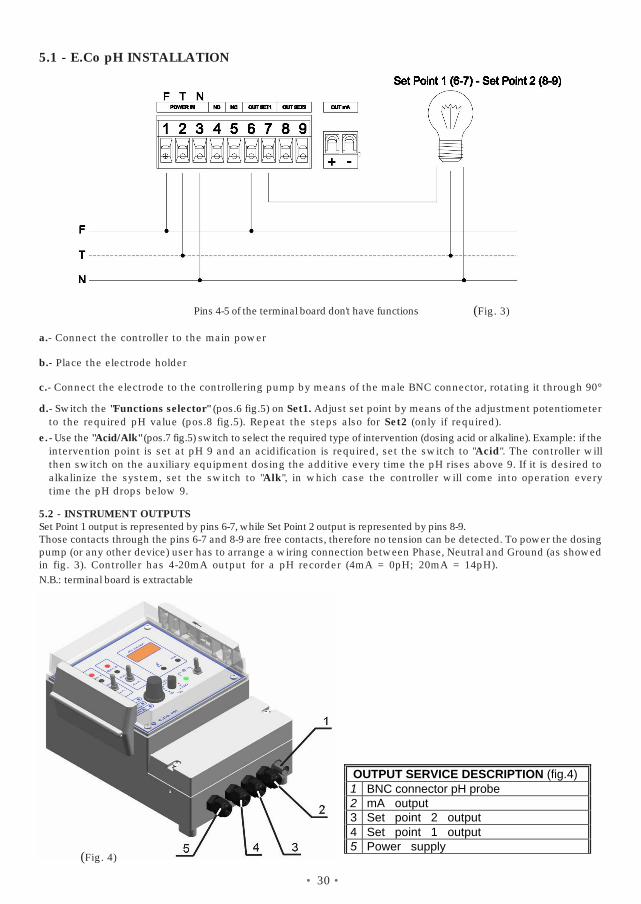
5.1 - E.Co pH INSTALLATION
b.- Place the electrode holder
e.
c.- Connect the electrode to the controllering pump by means of the male BNC connector, rotating it through 90°
time the pH drops below 9.
- Use the "Acid/Alk" (pos.7 fig.5) switch to select the required type of intervention (dosing acid or alkaline). Example: if the
d.to the required pH value (pos.8 fig.5). Repeat the steps also for Set2 (only if required).- Switch the "Functions selector" (pos.6 fig.5) on Set1. Adjust set point by means of the adjustment potentiometer
alkalinize the system, set the switch to "Alk", in which case the controller will come into operation everythen switch on the auxiliary equipment dosing the additive every time the pH rises above 9. If it is desired tointervention point is set at pH 9 and an acidification is required, set the switch to "Acid". The controller will
- Connect the controller to the main power
(Fig. 3)Pins 4-5 of the terminal board don't have functions
• 30 •
a.
5.2 - INSTRUMENT OUTPUTSSet Point 1 output is represented by pins 6-7, while Set Point 2 output is represented by pins 8-9.Those contacts through the pins 6-7 and 8-9 are free contacts, therefore no tension can be detected. To power the dosingpump (or any other device) user has to arrange a wiring connection between Phase, Neutral and Ground (as showedin fig. 3). Controller has 4-20mA output for a pH recorder (4mA = 0pH; 20mA = 14pH).N.B.: terminal board is extractable
OUTPUT SERVICE DESCRIPTION (fig.4)1 BNC connector pH probe2 mA output
3 Set point 2 output
5 Power supply(Fig. 4)
4 Set point 1 output
• 31 •
EN
GLIS
H
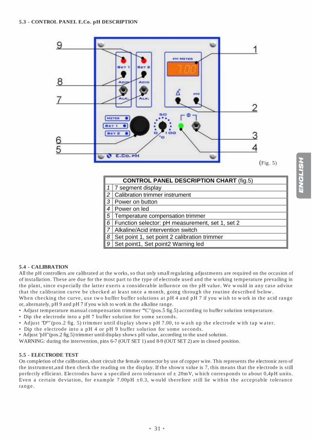
CONTROL PANEL DESCRIPTION CHART (fig.5)1 7 segment display2 Calibration trimmer instrument3 Power on button4 Power on led5 Temperature compensation trimmer6 Function selector: pH measurement, set 1, set 2 7 Alkaline/Acid intervention switch8 Set point 1, set point 2 calibration trimmer9 Set point1, Set point2 Warning led
(Fig. 5)
or, alternately, pH 9 and pH 7 if you wish to work in the alkaline range.• Adjust temperature manual compensation trimmer "°C" (pos.5 fig.5) according to buffer solution temperature.• Dip the electrode into a pH 7 buffer solution for some seconds.• Adjust "D°" (pos.2 fig. 5) trimmer until display shows pH 7.00, to wash up the electrode with tap water.• Dip the electrode into a pH 4 or pH 9 buffer solution for some seconds.
5.4 - CALIBRATIONAll the pH controllers are calibrated at the works, so that only small regulating adjustments are required on the occasion ofof installation. These are due for the most part to the type of electrode used and the working temperature prevailing inthe plant, since especially the latter exerts a considerable influence on the pH value. We would in any case advisethat the calibration curve be checked at least once a month, going through the routine described below.When checking the curve, use two buffer buffer solutions at pH 4 and pH 7 if you wish to work in the acid range
5.5 - ELECTRODE TESTOn completion of the calibration, short circuit the female connector by use of copper wire. This represents the electronic zero ofthe instrument,and then check the reading on the display. If the shown value is 7, this means that the electrode is stillperfectly efficient. Electrodes have a specified zero tolerance of ± 20mV, which corresponds to about 0,4pH units.Even a certain deviation, for example 7.00pH ±0.3, would therefore still lie within the acceptable tolerancerange.
WARNING: during the intervention, pins 6-7 (OUT SET 1) and 8-9 (OUT SET 2) are in closed position.• Adjust "pH" (pos.2 fig.5) trimmer until display shows pH value, according to the used solution.
5.3 - CONTROL PANEL E.Co. pH DESCRIPTION
• 32 •
5.8 - ELECTRODE HOLDERSThe company produce produce three different types of electrode holders: monotubular for immersion, electrode cell, and fordirect insertion in piping. It is essential to bear in mind that the distance between the injection point and the electrodemust never be less than one meter. When this is not possible, an appropriate mixer must be inserted betweenthe injection point and the electrode.
5.7 - RECONDITIONING
rinsing. Repeat this sequence three times, and then carry out another check measurement. If the reading remains erroneous,proceed to treatment 2.
The following chemical treatments may be carried out with a view to reconditioning the electrode. We list them in order ofincreasing aggressiveness as far as the bulb is concerned and would ask you to note that they will not necessarilyimprove the electrode quality, which in some cases may even be further reduced.1) Immerse the tip of the electrode in 0.1N hydrochloric acid (HCl) for 15 seconds, then rinse with water and
reimmerse the electrode in a 0.1N solution of sodium hydroxide (NaOH) for 15 seconds, followed by a second
5.6 - ELECTRODE CLEANING AND MAINTENANCE
2) Immerse the tip of the electrode in a 20% solution of ammonium bifluoride (NH2F-HF) for two or three minutes, then rinse withwater and make another check measurement. If the reading is still unacceptable, proceed to treatment 3.
When the electrode is not used for a lengthy period of time, it is important to preserve it immersed in a 3M potassium chloride(KCl) solution. The formation of deposits on the electrode will produce erroneous readings. The necessary cleaningaction depends on the type of deposits under consideration. In the case of thin deposits, shake the electrodein the manner of a thermometer or use a spray of distilled water. Organic residues or particularly resistant depositsshould be removed by chemical means. Mechanical cleaning of the bulb should be resorted to only in extremecases, but bear in mind that abrasion can lead to irreparable damage. If cleaning does not fully re-establish the efficacy of theelectrode, it may be that the electrode has aged. Ageing will show itself in the for of either a measurement error or aslow response. Ageing can be ascertained by thoroughly cleaning the electrode and then measuring a solutionof known pH: if the error exceeds 10%, reconditioning will have to be resorted to. If even this fails to re-establishcorrect electrode performance, there is no alternative to replacement.
3) Immerse the tip of the electrode in 5% hydrofluoric acid (HF) for 10 seconds, then rinse very thoughly in water and very quicklyin 5N hydrochloric acid (HCl), followed by a second rinsing in water. If the check measurement still produces unacceptablemeasurements, it only remains to change the electrode.