Embed Size (px)
Citation preview
ORNE TM- 1368
Contract No. W-7405-eng-26
XEACTOR D I V I S I O N
CONTROL CONCEPTS AND DIGITAL COMPITTER ANALYSIS OF THE MPRE FU-ID SYSTEM
M. E. LaVerne
*
OAK RIDGE IYATIONAL LABORATORY Oak Ridge , Tennessee
operated by UNION C m L D E CORPORATION
for the U. S. AWMIC EmRGY COMMISSION
GROW 1
Excluded from automat ic downgradi-ng and declass i f ica t ion

@c.:..,.:..: . . . . .... .:. ... i.... :.:&g :,<.$:* ' '. .. ., . . ... ..
iii
COI'XB3NTS
Introduct ion ................................................. Descript ion of t h e MPFE System ............................... System Control ............................................... Problem Areas ................................................
S t a b i l i t y of t h e Reactor .................................. Roil ing and Condensing Flow S t a b i l i t y ..................... S t a b i l i t y of t h e Complete System .......................... Inventory D i s t r i b u t i o n ....................................
MPRE F lu id System Analysis ................................... Resul ts of Computer Calculat ions ..........................
Conclusions .................................................. Appendix A ...................................................
System Equations .......................................... Turbine Eqinations ...................................... Jet-Pump Equations ..................................... Boi l e r Equations ....................................... Boi l e r Jet-Pump Equations .............................. Condenser Jet-Pump Equations ........................... Cent r i fuga l Pump Equations .............................
Appendix B ................................................... Two-Phase Pressure Drop Equations .........................
Preheating Sect ion Pressure Drop ....................... Boil ing Section Pressure Drop .......................... Overal l Pressure Drop ..................................
References ................................ .% ..................
1
2
5 16 16
17 18 19 19
27 37 43 43 43 46 4'7 49 5 1
53

l
CONTROL CONCEFTS AND DIGITAL COMPUTER ANALYSIS OF T€€E WRB FUTD SYSTEM
M. E. LaVerne
INTRODUCTION
The d i f f i c u l t c o n t r o l problems encountered i n steam p lan t s with
once-through b o i l e r s i n d i c a t e t h a t t h e r e i s good reason t o consider a
f r e s h approach t o the c o n t r o l of Rankine cycle systems when at tempting
t o develop a simple and r e l i a b l e space power p l an t . The s ingle- loop
Rankine cycle system of the MPRF: was devised i n 1958 t o ob ta in the
h ighes t poss ib le performance f o r a given r eac to r o u t l e t temperature
and t o ob ta in a systern s u f f i c i e n t l y simple t h a t t he p r o b a b i l i t y of i t s 1
opera t ing s a t i s f a c t o r i l y and unattended f o r 10,000 hours would be high.
An important f ea tu re of the system i s t h a t t he f l u i d dynamic and thermo-
dynamic performance c h a r a c t e r i s t i c s of the components and tne nuclear
c h a r a c t e r i s t i c s of the r eac to r can be in t eg ra t ed and matched t o e l imina te
most of the c o n t r o l func t ions required f o r a conventional power p l a n t
system.
N P n i l e t h e s t a b i l i t y and cont ro l problems o f the MPXE may be
unusual, t he re i s reason t o be l i eve t h a t they a r e s u b s t a n t i a l l y l e s s
complex than those of a conventional system. Because of t he unorthodox
cha rac t e r of t he system, these problem have been a t tacked from a number
of d i f f e r e n t angles. Analy t ica l work has led t o the formulation of
models f o r t h e Rankine cycle aiid these have been employed i n work with
both a d i g i t a l computer and an ana loge2 Five e l e c t r i c a l l y heated f ink ine
cyc le mockups have been b u i l t and operated, two with water arid th ree with
pota s s i urn. 3'4
flow in the water systems.
Glass and p l a s t i c p a r t s permit ted viewing of t he l i q u i d
The f i r s t portion of t h i s r epor t descr ibes the b a s i c system and
o u t l i n e s the manner i n which it i s designed t o operate . The var ious
s t a b i l i t y and c o n t r o l problems a r e out l ined t o i n d i c a t e t h e i r r e l a t ion -
s h i p and t o put each i n perspect ive. O f necess i ty , t h i s po r t ion r e l i e s
2
heavi ly on, and borrows equal ly heavi ly f r o m , t he work of o thers . The
second por t ion of t he r epor t summarizes the d i g i t a l computer ana lys i s
of the Rankine cycle system.
DESCRUPTIOM OF THE lIzpF3 SYSTEM
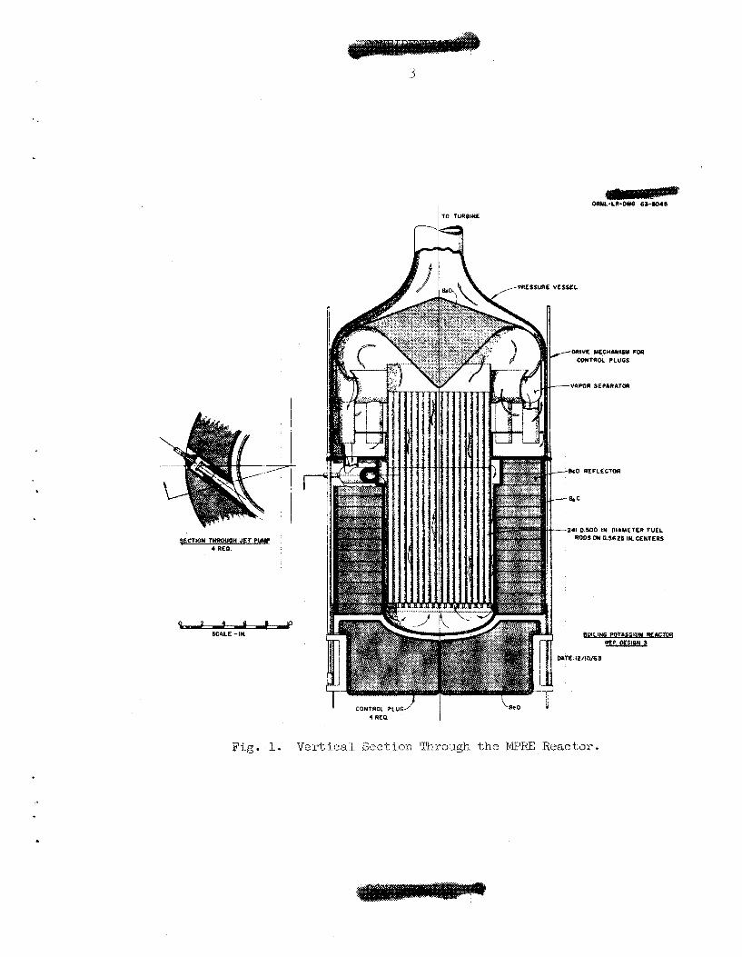
A v e r t i c a l s ec t ion through the MPRE r e a c t o r i s shown i n Fig. 1
The r eac to r core cons i s t s of a bundle of 1/2-in.-diam s t a i n l e s s s teel
tubes f i l l e d with s in t e red p e l l e t s of ful.ly enriched U02.
ends of these rods a r e f i l l e d with Be0 t o provide a r e f l e c t o r
region.
l i q u i d from tne vapor-liquid mixture leaving the core. Tests with a i r -
water mixtures i n d i c a t e t h a t vapor e x i t q u a l i t i e s i n excess of 9 9 can
be obtained. Wedge-shaped f l a t s l abs of Be0 a r e arranged r a d i a l l y
around the r eac to r core t o form a 3-in.-thick r e f l e c t o r . Reactor
con t ro l i s accomplished by r a i s i n g or lowering the bottom end plug,
which i s divided i n t o fou r independently operable quadrants. This i s
disciissed i n a companion paperJ5 a s a r e the r eac to r physics
heat t r a n s f e r and f l u i d flow problems of t he system.
The upper
A s epa ra to r i s p rodded a t the t o p of the core t o remove the
6 and the
,7
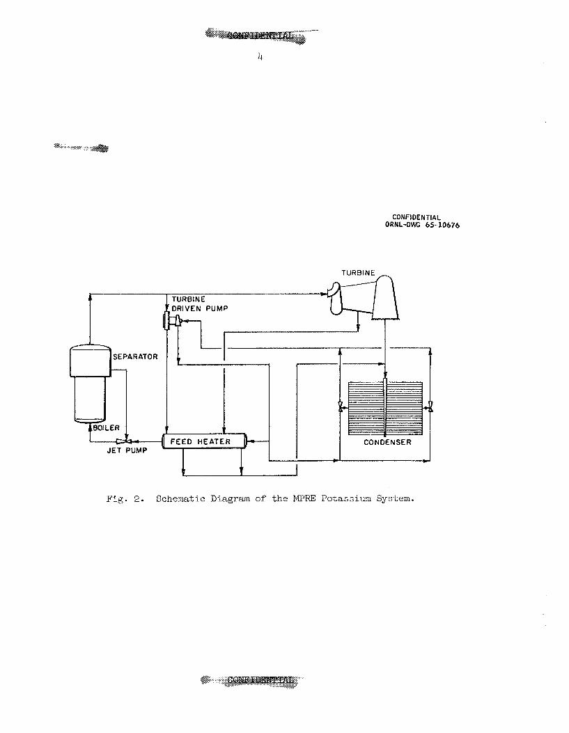
A schematic diagram of the system i s shown i n Fig. 2. Vapor flows
from the vapor separa tor t o the turb ine and then t o the condenser.
Liquid from the condenser i s returned by a j e t pump t o a c e n t r i f u g a l
feed pump from which it i s de l ivered t o t h e r eac to r core c i r c u i t through
a s e t of fou r j e t pumps opera t ing i n p a r a l l e l t o r e c i r c u l a t e t h e l i q u i d
from the vapor separa tor t o the core i n l e t .
The c e n t r i f u g a l feed pump of Fig. 2 i s not an i n t e g r a l park of the
turbine-generator u n i t bu t i s dr iven by a separa te tu rb ine . This arrange-
ment has t h e advantage t h a t it separa tes t he development problems and has
made it poss ib le t o proceed with tests on the MPRE system without H
turbine-generator u n i t . U n t i l a turbine-generator becomes ava i l ab le , it
can be simulated by a bypass valve o r o r i f i c e which w i l l have e s s e n t i a l l y
the sane flow c h a r a c t e r i s t i c s . O f course, vapor emerging from a valve
or o r i f i c e i n p a r a l l e l with the f r e e turbine-pump u n i t w i l l be somewhat
superheated. ??lis superheat can be removed e a s i l y by means of a cooler
. .-..:.> . ........... .: ......... .............. $&&@ .......... ......... ....
.I
- 6CILE -IN.
M
4
$%.:..:. ..,_.,.,. ;:. .......... < ..:p.:
CONFIDENTIAL ORNL-DWG 65-10676
TURBINE A
JET PUMP
DRIVEN PUMP h- l I
I I - c t I
1 - I
Fig. 2 . Schematic Diagram of the MPRE Potassium System.
5
downstream of t h e bypass o r i f i c e i n order t o simulate c l o s e l y the con-
dFt ion of t h e vapor leaving an actual. turbine.
o r i f i c e and cooler , o r "surrogate turbine", i s planned f o r i n s t a l l a t i o n
i n t h e Large Potassium System t e s t r i g .
a b o i l e r o u t l e t temperature of 15b°F would give a vapor temper&ture
en te r ing the condenser of about 1280"~.
heat would run only about 40 Btu/lb
za t ion of 887 Btu/lb (a t 1040°F).
Such a combination of
If t h e r e were no heat losses ,
Thus, t h e enthalpy of super-
as compared t o the hea t of vapori-
Separation of t h e p m p from t h e turbine-generator u n i t has a number
of a d d i t i o n a l advantages. It s i m p l i f i e s t h e design of t h e bear ing and
s h a f t system f o r t h e tur-uine and generator u n i t s and el iminates what
could be an awkward temperature d i . s t r ibu t ion and thermal d i s t o r t i o n
problem. It gives a much higher r e l i a b i l i t y f o r t h e pump than can be
obtained with an e l e c t r i c motor d r ive which would be dependent on t h e
r e l i a b i l i t y of many o the r components. Most important of a l l , however,
i t g r e a t l y eases t h e problems of matching t h e c h a r a c t e r i s t i c s of t h e
var ious components of t h e system and thus makes it possible -to obtain
a system t h a t r equ i r e s r e l a t i v e l y l i t t l e e l e c t r o n i c c o n t r o l equipment.
This, in t u rn , g r e a t l y increases t h e o v e r a l l r e l i a b i l i t y of t h e complete
power p l a n t .
s y s m CONTROL
The MF'RE presented a whole se t of abs t ruse design problems of
which t h e f i rs t and most important w a s t o ob ta in a system having good
dynaaic s t a ' u i l i t y c h a r a c t e r i s t i c s over a wide operating range. The
layout of Fig. 2 was devised i n an e f f o r t t o simplify t h e system and
t o minimize t h e number of components, including the mount of i n s t r u -
mentation and c o n t r o l equipment required. Reducing the nuniber of
components t o t h e bare e s s e n t i a l s makes it necessary t o t a i l o r each
component so t h a t it fits wel l i n t o tine system. One of -the innovations
i n t h e MPRE i s t h a t , unl ike conventional steam tu rb ine s y - s t e m s , no
t h r o t t l e valve i s employed. Instead, -the system i s intended t o operate
i n a manner much l i k e t h a t of a closed-cycle gas-turbine system, with
6
t he vapor v e l o c i t i e s through the tu rb ine piping and o the r elements of
t he system held s u b s t a n t i a l l y constant over a wide range of b o i l e r out-
pu ts while t he system pressure va r i e s e s s e n t i a l l y i n d i r e c t proport ion
t o the load. Figure 3 shows the inherent c h a r a c t e r i s t i c s of t he system.
Note t h a t t he b o i l e r pressure i s direct1.y propor t iona l t o the hea t
i npu t t o the b o i l e r .
Note, too, t h a t the speed of t he f r e e turbine-pump u n i t increases
gradual ly with b o i l e r output, and one of t he problems i s t o a d j u s t t he
s lope of t h i s curve so t h a t it y i e l d s a feed pump output t h a t f i t s the
system requiremeats e
It i s i m p l i c i t i n t he shove discussion t h a t the power inpu t t o the
b o i l e r and hence the weight flow or' vapor through the turb ine should be
cont ro l led t o maintain the speed of t he turbine-generator u n i t constant
i r r e s p e c t i v e of t he e l e c t r i c a l load. If the f l u i d system i s s t a b l e under
s teady-s ta te condi t ions throughout t he operat ing range--and t h e r e i s
s u b s t a n t i a l experience with e l e c t r i c a l l y heated t e s t r i g s t o i n d i c a t e
t h a t it i s - - t h e quest ion then becomes one of t he e f f e c t s on the
potassium vapor system of devia t ions i n turbine-generator speed from
the des i red values.
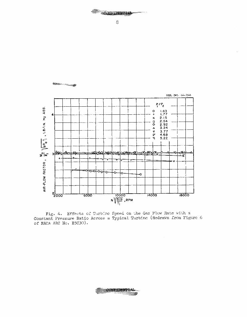
I n tu rb ines of t he type t h a t w i l l be used, t he pressure r a t i o
across the turb ine i s roughly t e n times the c r i t i c a l r a t i o . A s a
consequence, t he vapor flow through the turb ine w i l l behave e s s e n t i a l l y
as though it were passing through a c r i t i c a l p ressure drop o r i f i c e ,
and the tu rb ine r o t o r speed w i l l have v i r t u a l l y no e f f e c t on the vapor
flow r a t e (see Fig. 4). be held constant t o maintain the voltage and frequency; however, i f
something preven.ts t h i s , the tu rb ine speed may vary over a wide range
w.i.th no adverse e f f e c t s on the flow through the reac tor .
'Joe speed of the turbine-generator u n i t should
The q u a l i t y of -the mixture leaving the tu rb ine w i l l , of course,
change w i t h t he amount of work removed from the vapor. For e i t h e r a
s t a l l e d r o t o r or a complete runaway condition, t he turb ine would a c t as
a t h r o t t l i n g device; no work would be removed from the vapor, so
t h s t , as pointed out above, i t would e n t e r the condenser superheated,
I n p rac t i ce , t he extefit of t he turb ine speed v a r i a t i o n should be very
much l e s s - perhaps 1% - hence, t he change i n vapor q u a l i t y w i l l
1. .. .
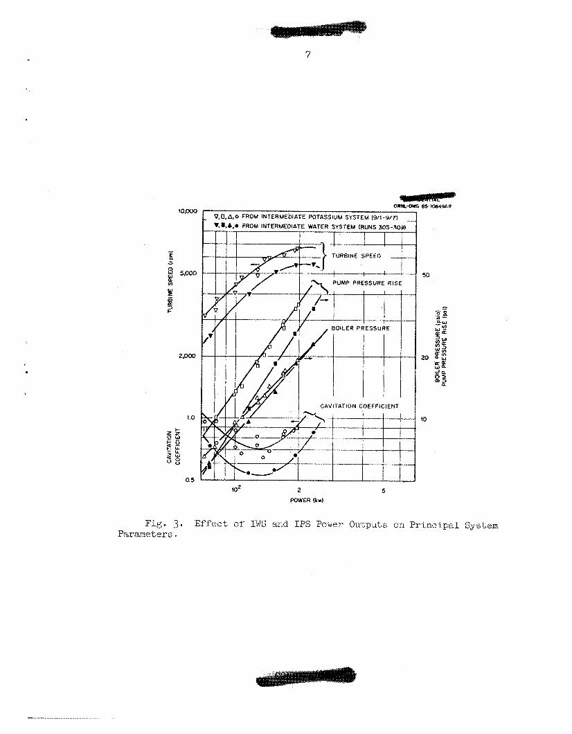
Fig. 3. Parameters.
7
6 5 t 0 8 4 9 A R
2 5 POWER (kw)
Effect of IWS and IPS Power Outputs on Principal System
. . . . . ..,<.-..I..
........... ... ............. ........ j ..;.e*+. .*, :.:.:.: .............. ... ..... :. .$.
.......
8
Fig. 4. E f f e c t s of Tur’oine Speed on t h e Gas Flow Rake with a Constant Pressure Ratio Across a Typical Turbine (Redrawn € r o m Figure 6 of NACA ARC No. E5C30).
probably never be s u f f i c i e n t t o produce superheating i n the vapor
mixture a t the condenser i n l e t . Even i f it d i d , t he e f f e c t on the
r a d i a t o r performance would be small s ince the o v e r a l l cycle e f f i c i e n c y
w i l l be only about l5$, so t h a t the increase i n the amount of heat t o
be dumped t o space could never exceed 15% of the reac tor thermal out-
put. Rough est imates ind ica t e t h a t the increase i n mean e f f e c t i v e
r a d i a t o r temperature t h a t would stem from the admission of superheated
vapor would be s u f f i c i e n t t o take care of the ex t r a amount of heat
t h a t would have t o be d iss ipa ted . Thus, so f a r a s the potassium
system i s concerned, changes i n turbine-generator speed and load
w i l l have v i r t u a l l y no e f f e c t on pressures and flow r a t e s except inso-
f a r a s t h e automatic c o n t r o l equipment i s designed to respond t o changes
i n the generator output frequency o r voltage and act8uate the cont ro l
plugs t o change the thermal power output of t he reac tor ,
The system l i q u i d inventory d i s t r i b u t i o n i s inherent ly s t a b l e
when -the components a r e properly matched. A t an appropriate b o i l e r
power leve l , the turb ine speed can be adjusted so t h a t the pump d i s -
charge pressure w i l l tend t o exceed the pressure required t o r e t u r n
condensate through the b o i l e r r e c i r c u l a t i o n j e t pump and i n t o t h e
bo i l e r . Under t h i s condition, t h e pump w i l l scavenge l i qu id from the
condenser u n t i l t he re a re so many bubbles i n the condensate l i n e leaving
the condenser t h a t the l i n e pressure drop w i l l increase. With t h i s
change, t he c a v i t a t i o n suppression head obtained by subcooling w i l l riot
be s u f f i c i e n t t o suppress c a v i t a t i o n i n the r a d i a t o r scav9nging j e t
p u ~ p . This u n i t w i l l c av i t a t e , and i t s discharge head w i l l drop. This,
i n turn, w i l l cause the c e n t r i f u g a l feed pump t o cav i t a t e , thus
decreasing i t s discharge head and flow.
i s quickly reached with the pump output reduced s u r f i c i e n t l y by
c a v i t a t i o n S O t h a t the discharge flow r a t e j u s t matches the system
requirements. Operation under t h i s condi t ion i s character ized by
small rapid f l u c t u a t i o n s i n the pump discharge pressure ( seve ra l cycles
p e r second) with the average pump pressure r i s e less than t h a t which
would be produced at, t h i s pwnp speed were the pump not i n cavi ta t ion .
A s t a b l e dynamic equilibrium
While cavi_tation i n the feed pump has been used t o c o n t r o l the
l i q u i d inventory d i s t r i b u t i o n i n s t a t i o n a r y steam power p lan ts ,
10
many engineers a r e not f a m i l i a r with t h i s approach. Since it i s an
important element i n t h e MPRE system, it seems des i r ab le t o present
here a d e t a i l e d p i c t u r e t o give an i n s i g h t i n t o the problems involved.
I n a t tempting t o e s t a b l i s h the condensate flow r a t e leaving the
condenser, t he f i rs t poin t t o observe i s t h a t t he condenser temperature,
and hence the pressure, w i l l depend on the hea t d i s s i p a t i o n r a t e .
Si.nce the boiler discharge flow r a t e i s l imi ted by a c r i t i c a l pressure
drop o r i f i c e , the b o i l e r pressure w i l l a l s o depend on (and be d i r e c t l y
propor t iona l t o ) t he power output.
absolute pressures i n the region between the condenser and the b o i l e r
i n berms of the head, H, i n f ee t of l iqu id , using the nota t ion of
Fig. 5.
It i s convenient t o express the
A t aay given b o i l e r power, t he pressure and f low r a t e of the
d r iv ing stream supplied t o the condenser scavenging j e t pump w i l l
be e s s e n t i a l l y constant and c lose ly r e l a t ed t o the b o i l e r p- I e s sure,
The pump can be proportioned so t h a t t h i s d r iv ing s t?”eamwil l give
it a flow capaci ty g r e a t e r than the condensate flow r a t e from the
condenser. Thus the j e t pump w i l l operate with s u f f i c i e n t vapor
inges t ion -to induce c a v i t a t i o n and reduce i t s output t o the flow
r a t e avaj-lable,
An i n s i g h t linto the opera t ing mode can be obtained by examining
t h e r e l a t i o n s involved. One of these i s the c a v i t a t i o n suppression
head, H a t the j e t pump i n l e t . T A ~ S i s given by S v,
where H i s t h e s t a t i c head assoc ia ted with the d i f f e rence i n l eve l
i s the head Hsc between the condensate manifold and the j e t pump,
ava i l ab le f r o m subcooling, and H - IS i s the head loss assoc ia ted
with the I”1uj.d flow frora the condensate manifold t o the j e t pump
i n l e t . The l a t t e r can be expressed a s
1 2
where G i s a constant t h a t depends on t h e l i n e diameter and length, 1

11
ORNL- DWG 65-5090
CONDENSER
Fig. 5. Liquid System Schematic Diagram Showing the Nomenclatilre Used to Indicate the Pressures at Key Points in -the System.
G i s ,the mass flow r a t e , and p i s the mean dens i ty of the bubbly l i qu id .
The s t a t i c head ava i l ab le from the d i f fe rence i n e l eva t ion between the
r a d i a t o r and j e t pump d e l i b e r a t e l y has been made small i n the various
t e s t r i g s being used t o s imulate the MPRE i n order t o approximate
zero-g condi t ions; it w i l l , t herefore , be neglected here.
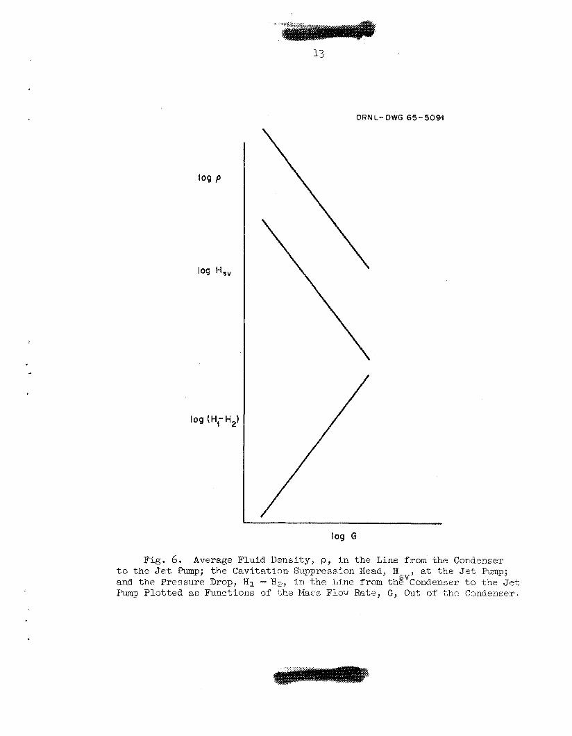
It is h e l p f u l t o consider, i n a q u a l i t a t i v e fashion, the e f f e c t s
of an increase i n the flow r a t e between the condenser and the j e t pump
a t a constant b o i l e r power output by examining a s e r i e s of curves. A s
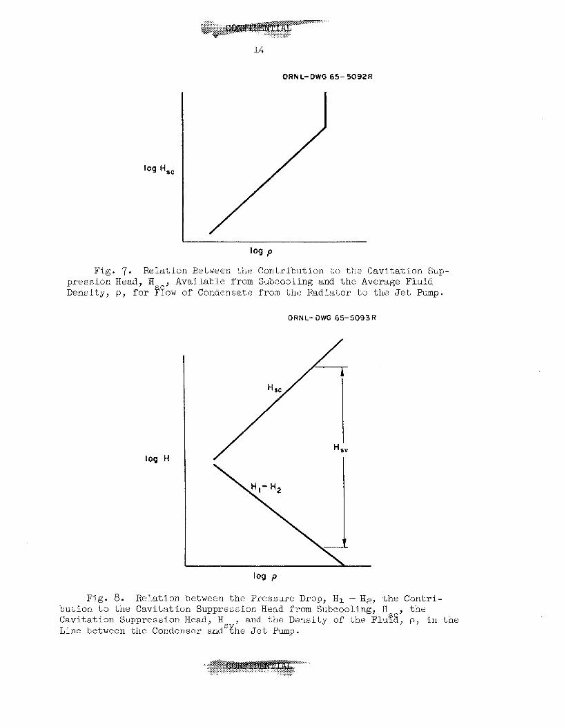
ind ica ted i n Fig. 6, t he average f l u i d dens i ty i n the l i n e from the
condenser t o the j e t pump w i l l decrease with an increase i n mass flow
r a t e , s ince the l i q u i d flow r a t e avai- lable w i l l remain s u b s t a n t i a l l y
constant and the concentrat ion of vapor bubbles i n the condensate mani-
f o l d and o u t l e t l i n e w i l l increase. This decrease i n dens i ty w i l l
i ncrease the head loss term, H. I - H2" and the f l u i d dens i ty f a l l s o f f , condensation i n the l i n e of t he
inc reas ing amount of vapor present will reduce the amount of subcool-
i n g t h a t w i l l occur ahead of t he j e t pump (see Figs. 6 and T) , .
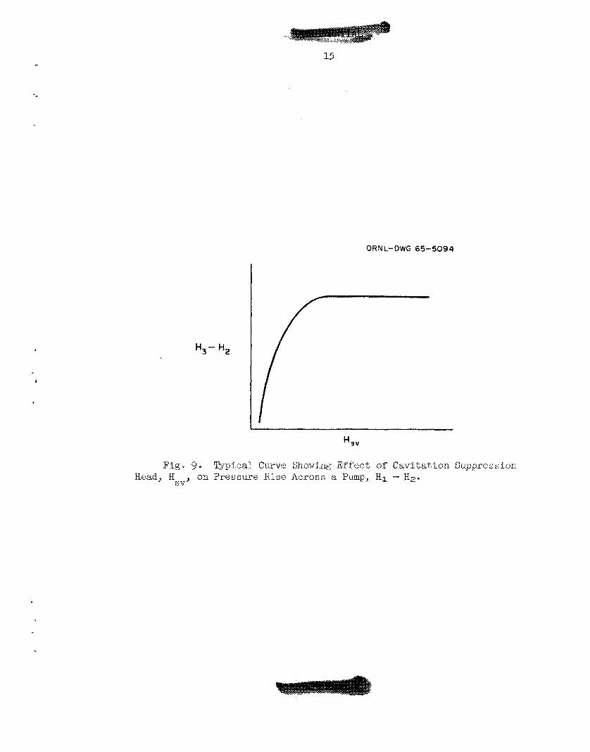
dens i ty i s reduced, both the increased pressure drop and the reduced
amount of subcooling w i l l a c t t o reduce t h e c a v i t a t i o n suppression
head a t the j e t pump i n l e t ( see Pig, 8).
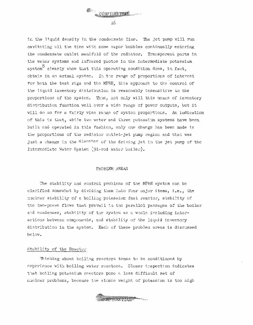
pressure r i s e a s shown i n Fig, 9.
A s t he mass flow i s increased
A s the
This w i l l reduce the j e t pump
Introducing the e f f e c t s of c a v i t a t i o n i n the feed pump makes the
s i t u a t i o n somewhat more comglex. Basteal ly , t he j e t pump should be
designed so t h a t i t has 8 somewhat g r e a t e r capac i ty than the feed pump
so t h a t cavlitation w i l l begin f i r s t i n t he J e t pump.
head of t he j e t pimp falls off s u f f i c i e n t l y , c a v i t a t i o n w i l l begin i n
the feed pump. Tne c h a r a c t e r i s t i c s of t he l a t t e r a r e e s s e n t i a l l y
s i m i l a r t o those shown i n Fig. 9 for t h e j e t pump, and hence the e f f e c t s
of c a v i t a t i o n i n the two pumps a r e s i m i l a r t o those out l ined above f o r
t h e j e t pump alone.
When t h e de l ive ry
It can be seen from an examination of Figs. 6 t o 9 t h a t , with excess
capac i ty i n the j e t p m p and cent r i f iga l . feed pmp, the l i q u i d inventory
d i s t r i b u t i o n should 'ne s t a b l e with no l i q u i d i n the r a d i a t o r tubes
except t he f i lms oil t he wal l s because the c a v i t a t i o n suppression head
ava i l ab le and the j e t pump flow r a t e increase r ap id ly with an increase
.
1 3
ORNL-DWG 65-5094
log G
Fig. 6 . Average Fluid Density, p, in the Line from the Condenser to the Jet Pump; the Cavitation Suppression Head, H at the Jet Sump; and the Pressure Drop, B-J, - H2, in the Line from the Condenser to the Jet; Pump Plotted as Functions of the Mass Flow Rate, G, Chit of the Condenser-
SV’
I4
ORNL-DWG 65- 5092R
log p
Fig . 7. Relation Between tiit: Contribution i o the Cavitat ion Sup- pression Head, Hc , Available from Subcooling and t h e Average Fluid Density, p , f o r $’?ow of Condensat,e f r o m t h e Radiator t o t h e Je t Pump.
ORNL-QWG 65-5093R
log H
Fig. 8. Relation between t h e Pressure Drop, HI - H2, Lhe Contri- but ion t o t h e Cavi ta t ion Suppression Head f r o m Subcooling, 11 , the Cavitation Suppression Head, H L ine between t h e Condenser and The J e t Pump.
and t h e Density of the Flu%, p , i n t h e s ’
.. . . ...
15
ORN L- DWG 65- 509 4
Fig. 9 a
SV'
Typical Curve Showing Ef fec t of Cavi ta t ion Suppression Head, H on Pressure H i s e Across a Pmp, H 1 -H2.
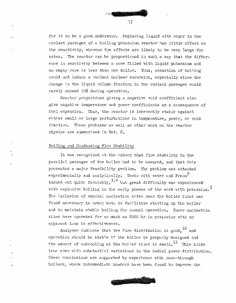
i n t h e l i q u i d dens i ty i n the condensate l i n e . 'The j e t pump wi1.1 run
c a v i t a t i n g a l l t h e t i m e with some vapor bubbles cont inual ly en te r ing
the condensate o u t l e t manifold of t h e r ad ia to r . Transparent p a r t s i n
t h e wa-ter systems and i n f r a r e d photos i n t h e i n t e m e d i a t e potassium
system c l e a r l y show t h a t t h i s operat ing condi t ion does, in f a c t ,
ob ta in i n an a c t u a l system, I n t h e range of proportions of i n t e r e s t
f o r both tlie t es t r i g s and t h e Mp.RE, t h i s approach t o t h e c o n t r o l of
'the l i q u i d inventory d i s t r i b u t i o n i s reasonably i n s e n s i t i v e t o t h e
proportions of t h e system. Thus, not only w i 1 . l t h i s means of inventory
d i s t r i b u t i o n funct ion we l l over a wide range of power outputs, bu t it
w i l l do SO f o r a f a i r l y wide range of system proportions. A n i nd ica t ion
of t h i s i s t h a t , while two water and Ynree potassium systems have been
b u i l t and operated i n tlnis fashion, only one change has been made i n
t h e proportions of t he r a d i a t o r o u t l e t - j e t p m p region and t h a t was
j u s t a change i n t h e dj-arfleter o f t h c d r iv ing j e t i n t h e j e t pump of t h e
Intermediate Water System {gl-rod water b o i l e r ) .
8
PROBLEM AmAS
The s t a b i l i t y and con t ro l problems of t he I"KE system can be
c l a r i f i e d somewhat by dividing them i i i to fou r major items, i.e., t h e
nuclear s t a b i l i t y of a b o i l i n g potassium f a s t reactor , s t ab i I . i t y of
t h e two-phase flows that p r e v a i l i n tine p a r a l l e l passages of t h e b o i l e r
and condenser, s t a b i l i t y of t he system a s a whole including i n t e r -
ac t ions between compnents , and s t a b i l i t y of tlie l i q u i d inventory
d i s t r i b u t i o n in t h e system. Each of t hese problem a reas i s discussed
be lov . Stabi l - i ty OP t h e Reactor
Thinking about b o i l i n g r eac to r s tends t o be conditioned by
experience with b o i l i n g water reactors . Closer i n spec t ion i n d i c a t e s
t h a t b o i l i n g potassium r e a c t o r s pose a l e s s d i f f i c u l t se t of
nucl-ear probkms, because the at0m.j.c weight of potassium i s t o o high
.A. .:.>...: . .>
D
f o r it t o be a good moderator.
coolant passages of a b o i l i n g potassium reac tor has l i t t l e e f f e c t on
the r eac t iv i ty , whereas the e f f e c t s a r e l i k e l y t o be very large f o r
water. The r e a c t o r can be proportioned i n such a way t h a t the d i f f e r -
ence i n r e a c t i v i t y between a core f i l l e d with l i qu id potassium and
an empty core i s l e s s than one do l l a r . Thus, cessa t ion of b o i l i n g
could not induce a v io len t nuclear excursion, e s p e c i a l l y s ince the
change i n the l i qu id volume f r a c t i o n i n the coolant passages would
r a r e l y exceed 10% during operation.
Replacing l i qu id with vapor i n the
Reactor proportions giving a negative void c o e f f i c i e n t a l s o
give negative temperature and power c o e f f i c i e n t s a s a consequence of
f u e l expansion. Thus, t he reac tor i s inherent ly s t ab le a g a i n s t
e i t h e r small o r la rge per turbat ions i n temperature, power, or void
f r ac t ion . These problems a s w e l l a s o ther work on the reac tor
physics a r e summarized i n Ref. 6.
Boiling and Condensing Flow S t a b i l i t y
It was recognized a t t he o u t s e t t h a t flow s t a b i l i t y i n the
p a r a l l e l passages of the b c i l e r had t o be assured, and t h a t t h i s
presented a major f e a s i b i l i t y problem. Tle problem was at tacked
tqrned out qu i te favorably, 3J
experimentally and a n a l y t i c a l l y ; Tests with water and Freon 9
but g rea t d i f f i c u l t y was experienced
with explosive b o i l i n g i n the e a r l y phases of t he work wlth potassium. 7
?"ne inc lus ion of s p e c i a l nucleat ion s i t e s near the b o i l e r i n l e t was
found necessziry i n order both t o f a c i l i t a t e s t a r t i n g up the b o i l e r
and t o maintain s t a b l e b o i l i n g f o r normal operation.
s i t e s have operated f o r as much as 8000 h r i n potassium with no
apparent loss i n e f fec t iveness .
These nucleat ion
Analyses i n d i c a t e t h a t t he flow d i s t r i b u t i o n i s good," and
operat ion should be s t a b l e i f the b o i l e r i s properly designed and
t h e amount of subcooling a t t he b o i l e r i n l e t i s small. This holds
true even with s u b s t a n t i a l v a r i a t i o n s i n the r a d i a l power d i s t r ibu t ion .
These conclusions a r e supported by experience with once-through
b o i l e r s , where intermediate headers have been found t o improve the
... ... :.:.:e. ....... .. . . . . .
13
flow d i s t r i b u t i o n and enhance s t a b i l i t y . The interconnect ing flow
passages of t h e MPRE cons t i t u t e , i n e f f e c t , continuous headers.
While burnout hea t f l u x l i m i t a t i o n s a r e important, both analyses
and t e s t da ta i n d i c a t e t h a t a s u b s t a n t i a l margin can be provided
between normal operat ing conditions and those t h a t would produce
burnout without increasing the r eac to r s i z e . 12
S t a b i l i t y of t he two-phase flow i n Yne p a r a l l e l passages of t he
condenser was a l s o considered t o be a p o t e n t i a l problem, However,
anaI.ytica1. work indicated t h a t condensing flow i n the tapered tubes
planned f o r tlie MPRE system should be s table ,13 and tes ts with
seven d i f f e r e n t tapered tube condensers have shown exce l l en t flow
d i s t r i b u t i o n and flow s t a b i l i t y c h a r a c t e r i s t i c s with only two
exceptions; i n one instance a poorly proportioned manifold gave a
poor d i s t r i b u t i o n under off-design conditions, and l a r g e amounts of
noricondensab1.es gave poor flow d i s t r i b u t i o n s i n t h e condensers of
t h e water systems. 8
S t a b i l i t y of t he Complete System
When a l l of t h e components ol" a system a r e coupled together, it
i s important t h a t t h e system a s a whole respond well t o changes i n
power. All of t h e a n a l y t i c a l , analog, and e l e c t r i c a l t es t r i g
experrenee i n d i c a t e s t h a t -the MPRE system i s s t a b l e and responds
we1.1 t o changes i n hea t inp-ut t o t h e b o i l e r .
operat ion was described li.n a previous sec t ion . The pr i -nc ipa l l i m i -
t a t l o n s observed a r e t h a t -the theimai i n e r t i a of t h e system i s such
t h a t it i s not possible t o increase the "steaming r a t e " more r ap id ly
than about I-$ of full power p e r second. A reduct ion i n steaming r a t e
ought not exceed about 0.3% p e r second f o r a power l e v e l change equal
t o about 20$ o f ful.1 power i f foaming i n tlie b o i l e r and t h e expansion
tank a r e t o be avoided. While no d i f f i c u l t y with burnout has been
experienced when foaming has been encountered, it appears b e s t t o
avoid t h i s condition. From the nuclear r eac to r c o n t r o l standpoint,
t h e r e i s a s t rong incent ive t o l i m i t the r a t e of change of t he b o i l e r
hea t output .Lo about 0.3% p e r second.
rT'he mode of
A survey of space vehicle
14 requirements i n d i c a t e s t h a t t h i s i s an acceptable value.
I
Inventory Dis t r ibu t ion
Tine vapor passages c o n s t i t u t e t h e bulk of the volume i n a Rankine
cycle f l u i d system. Since it i s important t h a t t he b o i l e r not run
d r y , system i n which it belongs and not be allowed t o accumulate i n some
port ion of the vapor region.
by keeping the vapor v e l o c i t i e s s u f f i c i e n t l y high t o sweep along any
small accumulations of l i qu id t h a t may form. This can be done through-
out t he vapor system except close t o the o u t l e t of the condenser
tubes. The vapor ve loc i ty w i l l vary roughly a s the square root of
the absolute temperature.
ve loc i ty i n the vapor region a t b o i l e r pressure i n going from f'ull
t o 109 power.
g rea te r , but there the passage diameters have been made s u f f i c i e n t l y
small t h a t surface tens ion w i l l draw the t h i c k l i qu id film on t h e
wal l s i n t o slugs of l l qu id in te rspersed between bubbles. Thus the
problem of maintaining the desired l i qu id inventory d i s t r i b u t i o n
becomes one of assur ing t h a t t he condenser w l l l b e scavenged a t all
times so t h a t it w i l l be maintained i n a "dry sump" condition.
por t ion of the work with %he analog and the e l e c t r i c a l l y heated
system mochps has been concerned w i t h t h i s problem.
the analog and the t e s t r i g s has shown t h a t , by operat ing with the
b o i l e r feed pump cavi tq t ing , t h e l i q u i d inventory d i s t r i b u t i o n i s
s t a b l e and no c o n t r o l a c t i o n need be exercised by the operator t o
allow f o r changes i n power, condenser temperature, o r the l i ke .
t he bulk of the l i qu id must be kept i n t h a t por t ion of t he
This i s accomplished i n the WR?Z system
This leads t o only a 12% decrease i n
I n the condenser o u t l e t region the e f f e c t i s much
A
Work with both
MPm FLIJID SYSTEN ANALYSIS
Preliminary analyses of the problem of system flow d i s t r ibu t ion , s t a b i l i t y , and c o n t r o l have been presented i n previous reports . 1,15,16
From th is work a c a l c u l a t i o n a l procedure has evolved t h a t gives a
comprehensive a n a l y t i c a l t o o l f o r i n v e s t i g a t i n g the e f f e c t s of any
20
system parameter on t’ne flow and pressure d i s t r i b u t i o n .
i.s concerned with the l a t t e r problem i n the s teady-s ta te . This
ana lys i s does not purport t o t r e a t the s t a b i l i t y o r con t ro l of t h e
system, except i n so fa r a s they a r e involved i n the t r a n s i t i o n from one
s teady-s ta te t o another.
s t a t e equations throughout, t reatment of dynamic s t a b i l i t y i s excluded,
although s e n s i t i v i t y c o e f f i c i e n t s f o r any parameter a r e r e a d i l y de te r -
mined.
The present work
Spec i f i ca l ly , because of the use of steady-
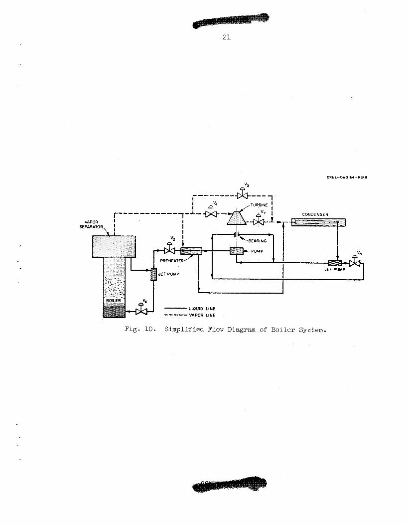
A s impl i f ied diagram of the system used a s the model f o r t h i s
ana lys i s i s shown i n Fig. 10.
behavior of t h i s system were derived and means devised f o r t h e i r
so lu t ion . Because of t he i m p l i c i t nature of many of the r e l a t ionsh ips ,
an i t e r z t i v e so lu t ion of tlie system equations i s required f o r tlie most
pa r t .
off-design-point program with which system opera t ing condi t ions rmy be
determined, given a s e t or system parameters.
Tlie governing equat ions f o r the s t a t i c
The digi ta l -computer program w r i t t e n f o r t h i s purpose i s an
A f i rs t s t e p i n the ana lys i s was t o s e t up the equations i n t e r -
r e l a t i n g system parameters with component c h a r a c t e r i s t i c s and operat ing
condi t ions.
i-n Appendix A i n approximately the order of so lu t ion used by t h e
program.
the e xpe rime n t a l l y de t e mi ne d c ompone n t c ha r a c t e r i s t i c s . between expe rime n-La 1 data r‘-22 and enpi.ri.cally derived r e l a t i o n s a r e
shown i n Figs . 11 through 1.8.
The s e t of equations used i n t h i s ana lys i s i s presented
The equations include empir ica l expressions designed t o f i t
Coinpa r i sons
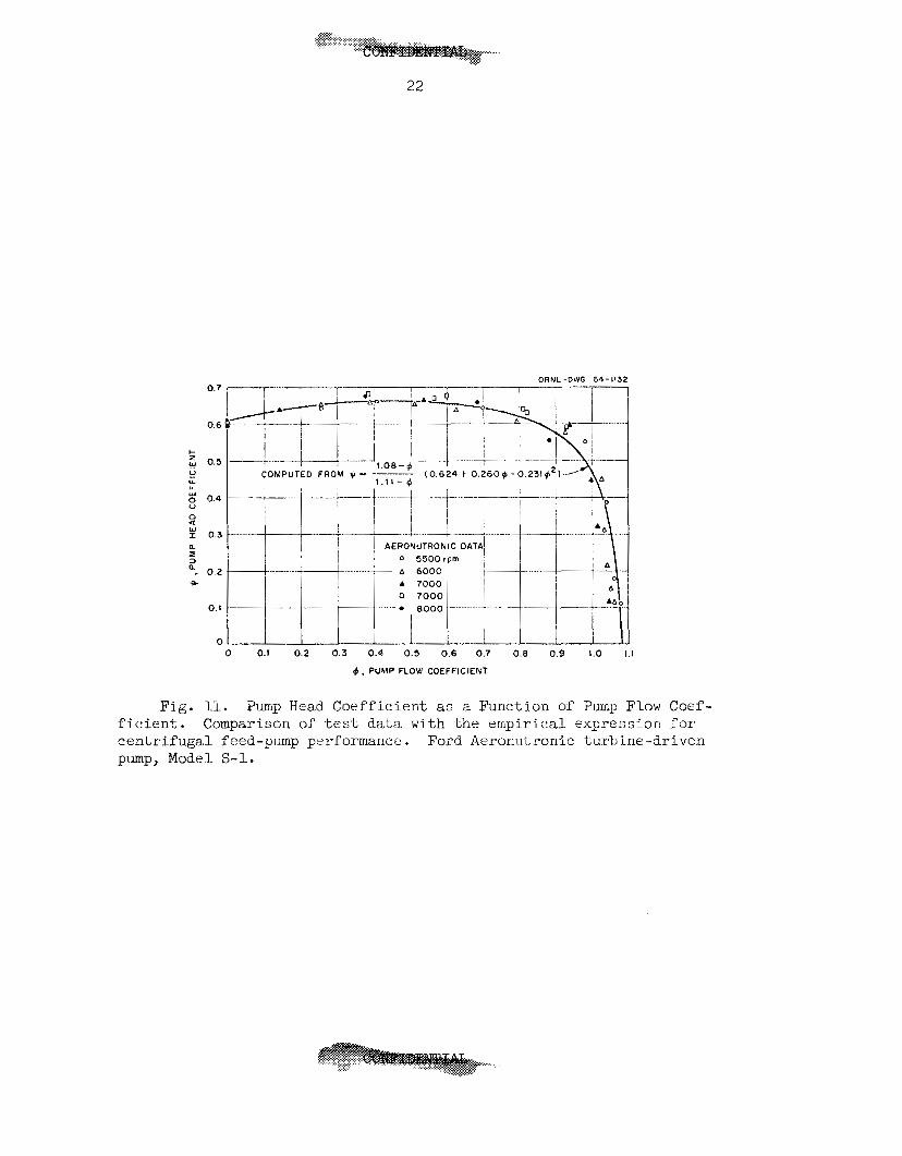
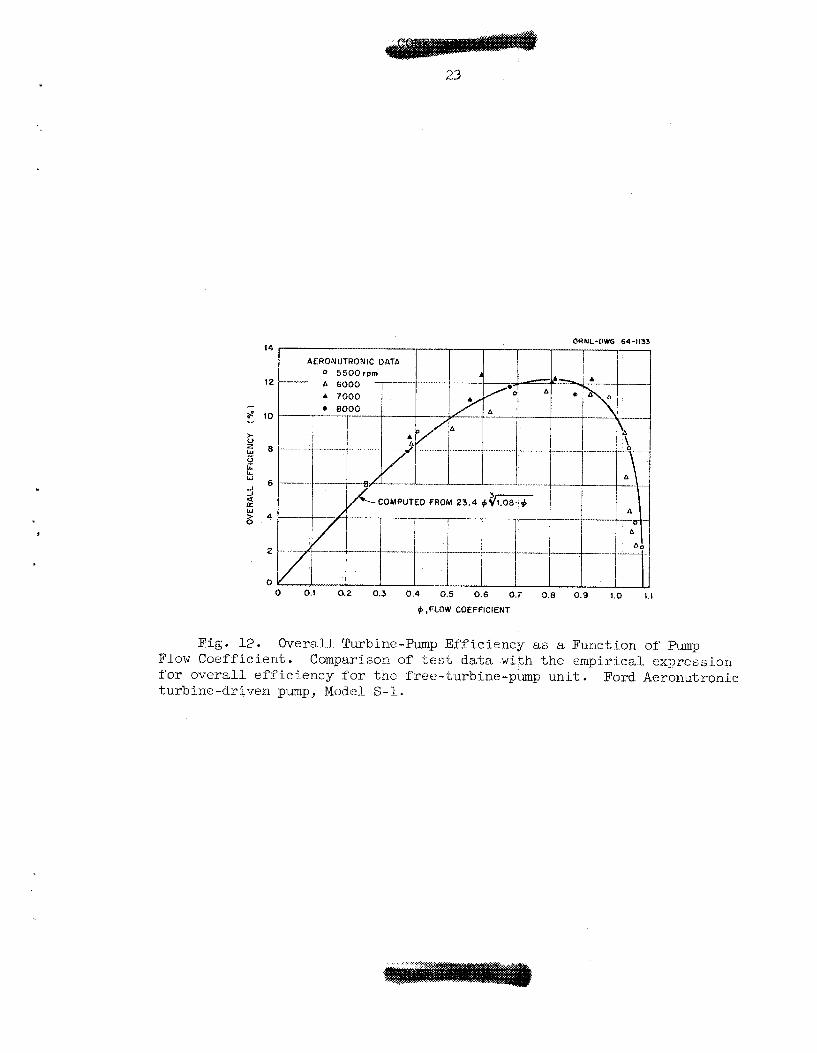
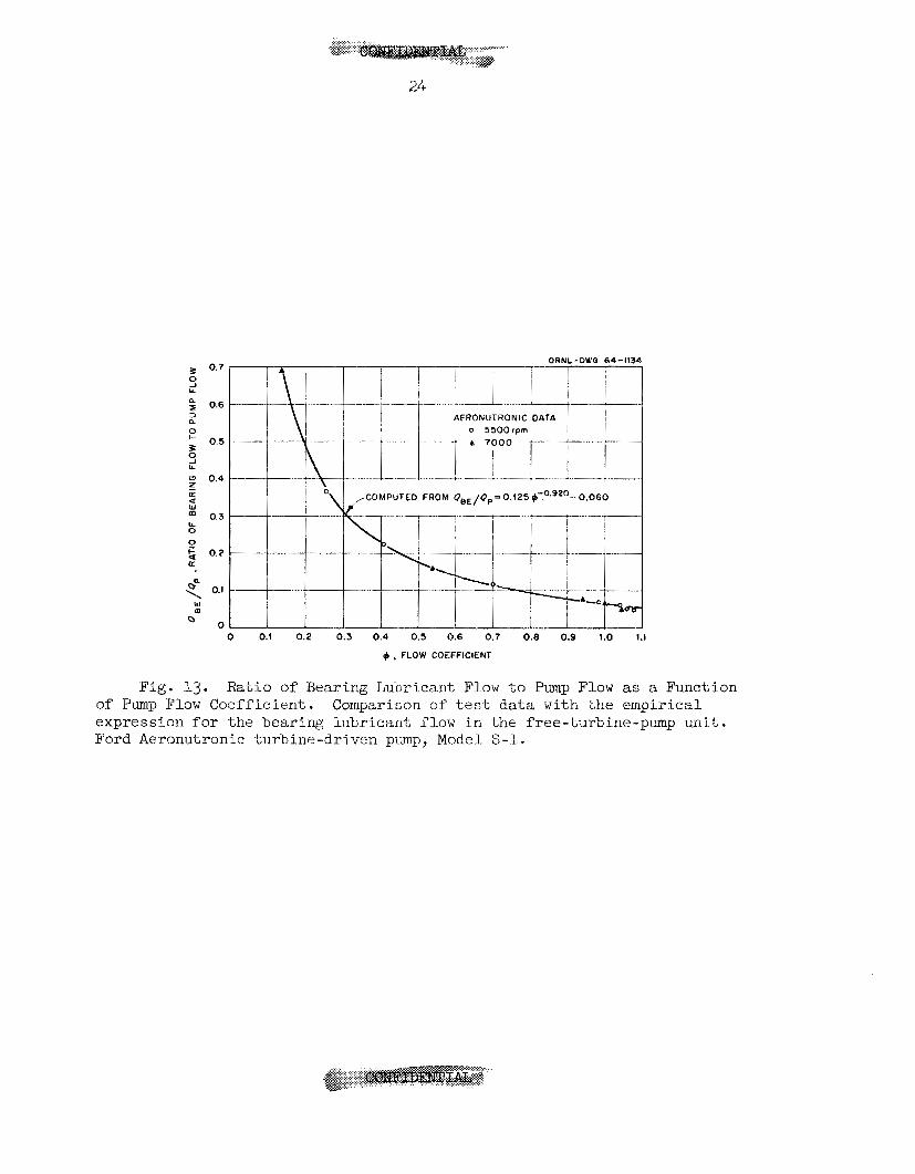
For the free-turbine-pm-p u n i t , Pigs. ll through 13 show the
pimp head coe f f i c i en t , t he u n i t overall- e f f i c i ency , and the r a t i o of
bear ing- lubr icant flow t o t o t a l pump flow, respec t ive ly , a l l a s
fun t ions of the flow coef f ic ien t .17
the da ta a r e ( A - 4 7 ) , ( A - U ) , arid (A-)+g) , r espec t ive ly .
The equations derived t o represent
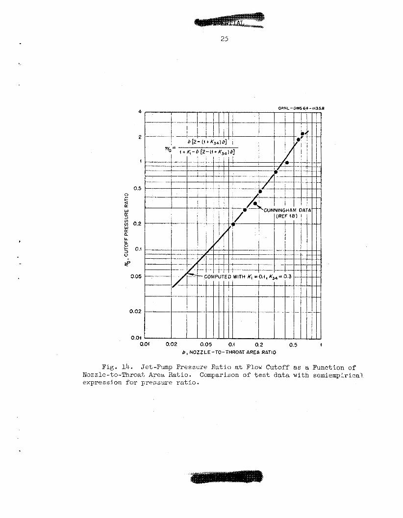
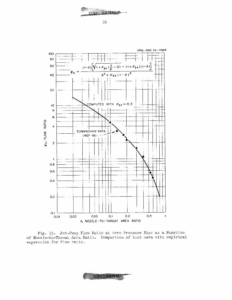
%ne p res su re - r a t io and f low-ra t io in t e rcep t s , respec t ive ly , f o r
t he jet-pump-flow c h a r a c t e r i s t i c s a r e shown a s func t ions of t h e
nozzle- to- throat area r a t i o i n Figs. 14 and 15. T’ne corresponding
eq%ations18 are (-4-17) and ( A - 1 8 ) , i n t h a t order, ( A - 1 8 ) being t h e
same a s t h a t used by CunainghamlB except f o r a reorder ing f o r
computational convenience.
. ......
ORNL-DWE 64-i434R
Fig. 10. Simplified Flow Diagram of Boiler System.
,.. i... .
22
O R N L - O W 64- I132
COMPUTED FROM +
a I
*
0 0.1 0.2 0.3 0.4 0.5 0.6 0.7 0.8 0.9 1.0 1.1
9. PUMP FLOW COEFFICIENT
Fig. 11. Pump Head Coefficient as a Function of P u p Flow Coef- ficient. centrifugal feed-pump performance.
Comparison of test data w i t h t h e empirical expression for Ford Aeronutronic iurbine-driven
pump, Model S-1.
.. . .. ...
23
ORNL-OWG 64-1133
I'
9 .FLOW COEFFICIENT
Fig. 12. Flow CoefPicient. f o r overal l e f f i c i e n c y f o r the free-turbine-pump unit. turbine-driven pump, Mudel S-1.
Overall Turbine-Pump Eff ic iency as a Function of Pump Comparison of test data with t h e empirical expression
Ford Aeronutronic
0.7
0.6
0.5
0.4
... .
24
COMPUTED FROM OeE/Op=0 . t25 +-0'920-0.060
0 0.1 0.2 0.3 0 .4 0.5 0.6 0.7 0.8 0.9 1.0 1.1
+ , FLOW COEFFICIENT
Fig. 13. Ratio of Bearing Lubricant Flow to Pump Flow as a Function of Pump Flow Coefficient. expression for the bearing lubricant flow in the free-turbine-pump unit. Ford Aeronutronic turbine-driven pump, Model S-l.
Comparison of test data with the empirical
25
4
2
i
0.5
0 %
5 z 0.2
8 kj 6.1
9
K w
W Q:
IA a
0
0.05
0.02
0.0i
R
Q.Of 0.02 0.05 0.1 0.2 0.5 I b , NOZZLE-TO-THROAT AREA RATIO
Fig. 14. Jet-Pump Pressure Ratio at Flow Cutoff as a Function of Nozzle-to-Throat Area Ratio. expression f o r pressure r a t i o .
Comparison of t e s t d a t a with semiempirical
26
ORNL-DWG 64- 4436R
MPUTED WITH K 3 4 = 0 .
0.04 0.02 0.05 0.1 0.2 0.5
6, NOZZLE-TO--THROAT AREA RATIO
Fig . 15. Jet-Pump Flow Ra t io at; Zero Presslire Rise as a Function oT Nozzle-to-Throat Area Ratio. expression I”or fI.ow ratio.
Comparison of t e s t data w i t h empirical
... . .
b
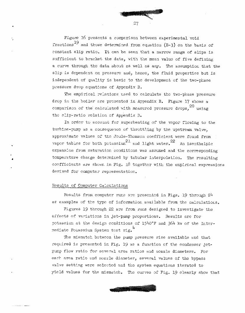
Figure 16 presents a comparison between experimental void
fractions'' and those determined from equation (B-3) on the b a s i s of
constant s l i p r a t io . It can be seen t h a t a narrow range of s l i p s i s
s u f f i c i e n t t o bracket t he data, with tlze mean value of f i v e def ining
a curve through the da ta about as w e l l a s any.
slip i s dependeat on pressure and, hence, "cne f l u i d proper t ies but i s
independent of q u a l i t y is bas ic t o t he development of the two-phase
pressure drop equations of Appendix 13,
The assumption t h a t the
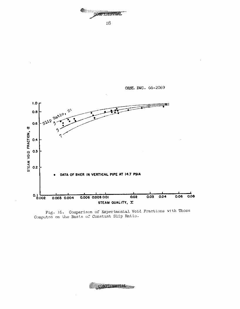
Tne empir ical re la t iOns used t o ca l cu la t e the two-phase pressure
drop i n the b o i l e r a r e presented i n Appendix B. Figure 17 shows a
comparison of the calculated with measured pressure drops, using
the s l i p - r a t i o r e l a t i o n of Appendix B.
20
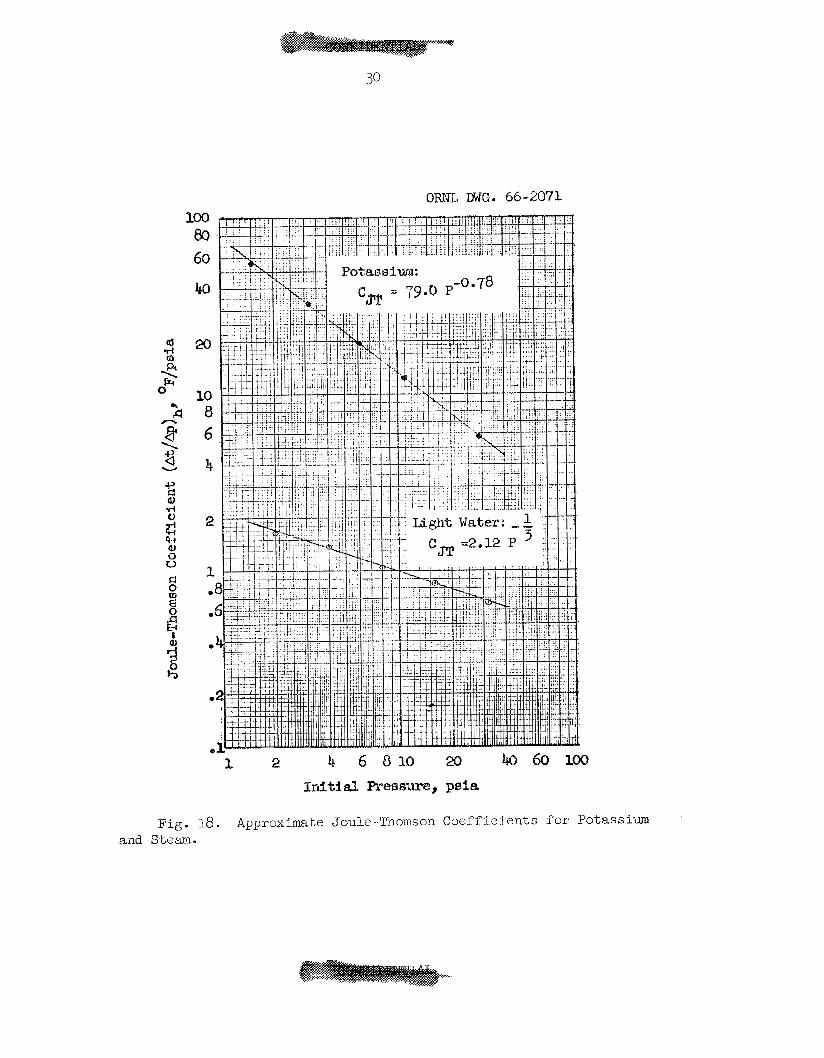
I n order t o account f o r superheating of the vapor flowing t o the
turbine-pump as a consequence of th ro t t l - ing by the upstream valve,
approximate values of the Joule-Thomson c o e f f i c i e n t were found from
vapor t a b l e s f o r bo%h pctassium2'- and l i g h t water.22
expansion from s a t u r a t i o n conditions was assumed and the corresponding
temperature change determined by t a b u l a r in te rpola t ion . The r e s u l t i n g
c o e f f i c i e n t s a r e shown i n Fig. 18 toge ther with the empir ical expressions
derived f o r computer representat ion.
An i s e n t h a l p i c
Results of Computer Calculat ions
Eesults from computer runs a r e presented i n Pigs. 1-9 through 24
a s examples of tne type of i n f o m a t i o n ava i lab le from the ca lcu la t ions .
F i g ~ ~ e s 19 t'nrough 22 a r e from runs designed t o i n v e s t i g a t e the
e f f e c t s of v a r i a t i o n s i n jet-pump proportions. Kesults a r e f o r
p o t u s s i m a t tne design conditions of 1540°F and 364 kw of the In t e r - 4
mediate Potassium System t e s t rig.
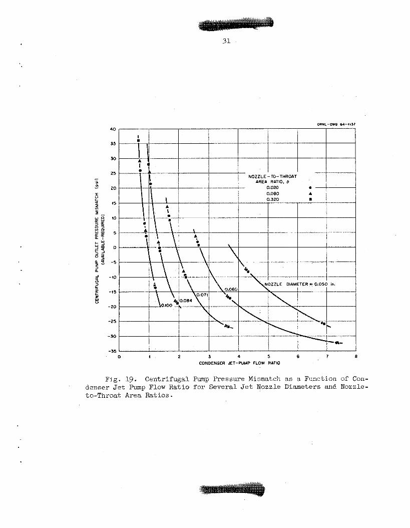
Die mismtch between the pump pressure r i s e ava i lab le and t h a t
required i s p r e s m t e d i n Fig. 19 as a funct ion of the condenser j e t -
pump flow r a t i o f o r s e v e r a l a rea r a t i o s and nozzle diameters. For
each area r a t i o and nozzle diameter, s e v e r a l values of the bypass
valve s e t t i n g were se lec ted and the system equations i t e r a t e d to
y i e l d values f o r the mismatch. The curves of Fig. 19 c l e a r l y show t h a t
28
I 1 1 I I I I 1 I L
ORNL DWG. 66-2069
Q DAYA OF SHER IN. VERTICAL PIPE AT la.? PSlA
STEAM QUALITY, X
Fig. 16. Comparison of Ekperimen-tal Void Fractions with Those Computed on t h e Basis of Constant Slip Ratio.
ORNL DWG. GO-2070
Fig. 17. Compari.son Between Measured and Calculated Pressure Drops.
Calculated s l i p r a t i o = 0.167~-
. ...-.
TLOZ-99 '3M I'1psLIO
ORNL-DWfi 64-4137 40
35
30
25 - 5 AREA RATIO, b
20 P - r v 2 15 2 4 - a 10 K,W
2 5 8 2 5
Y d 0 +-z 2 % 5
d i - (5
a a a 1 4-w
5 -5
a -40
3
t r W V
-20
-25
- 30
-35 O I 2 3 4 5 6 7 8
CONOENSER JET-PUMP FLOW RATIO
Fig. 19. Centrifugal Pump Pressure Mismatch as a Function of Con- denser J e t Pump Flow Ratio for Several Jet Nozzle Diameters and Nozzle- to-Throat Area Ratios.
t he mismatch i s not dependent on a rea r a t i o bu t i s dependent only on
nozzle diameter.
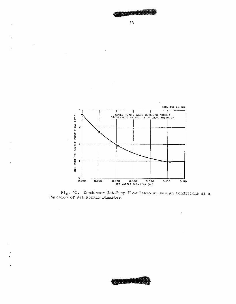
A cross-p lo t of Fig. 19 a t zero mismatch then y i e l d s Fig. 20,
which shows the e f f e c t of nozzle diameter on condenser jet-pump flow
r a t i o a t design condi t ions f o r a balanced system.
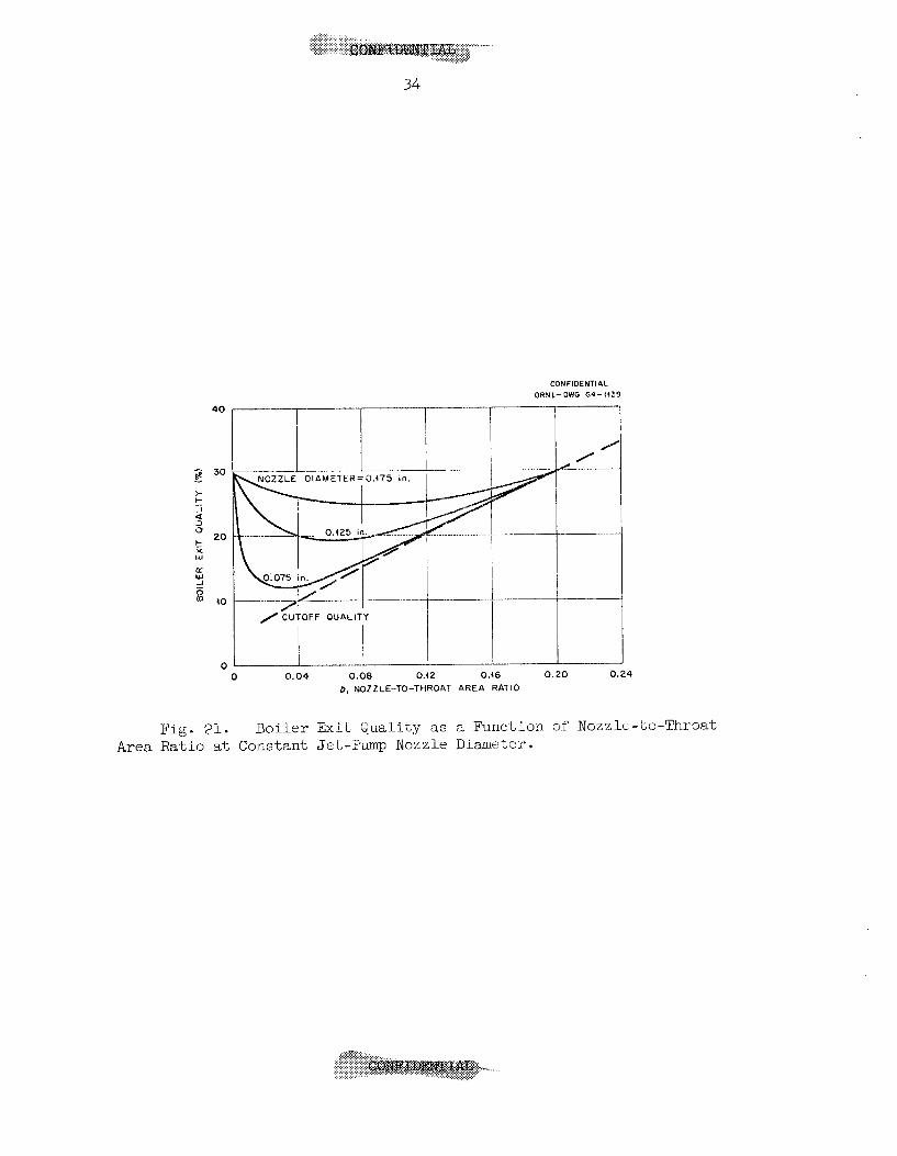
F i g u e s 21 and 22 show t h e e f f e c t s of b o i l e r jet-pump proport ions
on the b o i l e r operat ing qua l i ty . It i s t o be noted t'nat, in Fig. 21,
t he curves f o r a l l nozzle diameters converge on a l imi t ing q u a l i t y of
29.876, both a s t he area r a t i o , b., approaches zero and a s it approaches
a value of approximately 0.2.
t h e q u a l i t y remains constant a t 29.8%.
i s p l aus ib l e can be seen from the following phys ica l argument. For
b ' s approaching zero (corresponding to very- la rge t h r o a t s ) , t h e
e f f i c i e n c y of energy t r a n s f e r and, a s a consequence, t he pressure r i s e
i n the pumped f h i d approach zero. Wit'n zero pressure r i s e i n the
jet-pump, the b o i l e r then func t ions a t a q u a l i t y c h a r a c t e r i s t i c of i t s
opera t ion as a n a t u r a l c i r c u l a t i o n system, i n t h i s case giviilg a vapor
e x i t q u a l i t y of 29.8$, independent of je-t-pump proport ions,
marked "cutoff qua l i ty" dzf ines the quaI.ity, f o r any value of '0, f o r
zero pressure rise i n the j e t pump.
of 29.876 f o r b := 0.2, t h u s def in ing the right-hand convergence poin t
f o r all1 of t h e constant-nozzle-diameter curves.
Fcr a lL values of b g r e a t e r than 0.2,
Piat t h i s shape of t he c u w e s
The l i n e
This "cutoff" l i n e y i e l d s a q u a l i t y
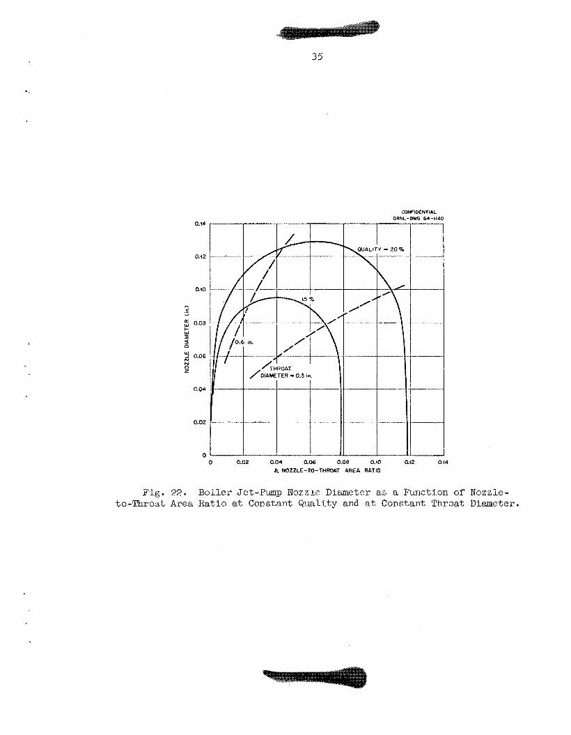
A cons tan t -qua l i ty c ross -p lo t der ivable from curves such a s those
of Fig. 23. i s shown i n the form of t he s o l i d l i n e curves i n Fig. 22- The
dashed l i n e curves represent t he reLa-Lion between. nozzle diameter and
b a t a constant t h r o a t diameter a s derived from the d e f i n i t i o n of b.
Z"ne i n t e r s e c t i o n s of t he two s e t s of l i n e s then show the operat ing
q u a l i t i e s and the CorrespoiLding jet-pump proportions.
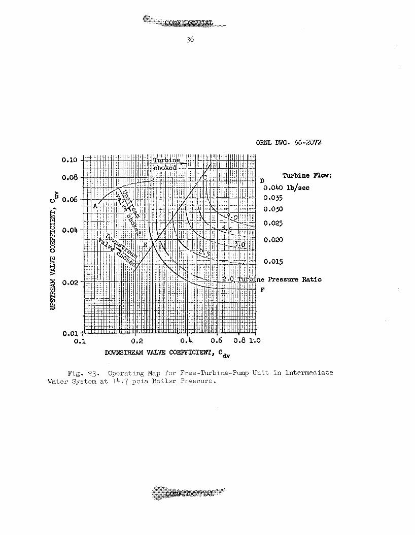
As ind ica ted previously, a ca rd ina l p r inc ip l e i n t h e system
opera-Lion i s t h e use of c r i t i c a l flow through key r e s t r i c t i o n s i n the
vapor l i n e s i n order t o y i e ld a unique r e l a t i o n between power and the
b o i l e r pressure and vapor production. Figure 23 was prepared from a
s e r i e s of corrrputer m n s as an a i d i n the s e l e c t i o n of t he appropriate
vaI.ues f o r t he r e s i s t ances , upstream and downstream of the turb ine ,
required f o r any des i red opera t ing condi t ion. Line ABCD de l inea te s
. ..
33
QRNL-DWG 64-4438
I I I
0.050 0.060 0.070 0.080 0.090 0.400 0.440 JET NOZZLE DIAMETER ( In . )
Fig. 20. Condenser Jet-Pimp Flow R a t i o a t Design Conditions as a Function of Je t Nozzle Diameter.
40
3 30 - t
_I 4 3 0
t
20 c X W
a W 1 ' 40
0
CONFlDENTlhL ORNL-OWG 64-4439
-I ~ __ ~ . ~
,/ CUTOFF QUALITY
0 0.04 0.08 0.42 0.46 0.20 0.24 b, NOZZLE-TO-THROAT AREA RATIO
Fig. 21. Area Ratio at Constant Jet-Pump Nozzle Diasaeter.
Boiler Exit Quality as a Function of Nozzle-to-Throat
.-....
I
35
0.14
0.12
0.10
e - 2 0.08
2 W H
W N N 0 z
-1 0.06
0.04
0.02
0
CONFIDENTIAL ORNL-OWG 6.-414
- 20% +
0 0.02 0.04 0.06 0.oe 0.fO 0.!2 0.!4 b. NOZZLE-TO-THROAT AREA RATIO
Fig. 22. B o i l e r Jet-Pump Nozzle Diameter as a Function of Nozzle- to-Throat A r e a Ratio at Constant Quality and at Constant Throat Diameter.
0.10
0.08
u 5; 0.06
0.82
0.01 a
ORNL BWG. 66-2072
Turbine
0.0& Ib/sec 0.035 0.0%
D
0,025
0.020
i e Preseure Ra F
Flaw:
.tis
Fig. 23. Operating Map for Free-Turbine-Pump Unit i n Intermediate Water System at 14.7 ps ix Boiler Pressure.
37
t he boundary below which t h e upstream valve i s choked. Similarly,
l i n e BEF e s t a b l i s h e gion i n which the turb ine operates with
choked nozzles, i.e., t o the r i g h t and above B;EF, Final ly , t he
downstream valve i s found t o be choked above and t o the l e f t of l i n e
CE. Lines of constant tu rb ine flow and turb ine pressure r a t i o have
been superimposed on the region defined by DBEF, i.e., t he region
i n which both the turb ine and the upstream valve a r e choked.
Operation of both the a c t u a l systen: and i t s analog i s normally
res t rTcted t o region DCEF, where the downstream valve i s not
choked =
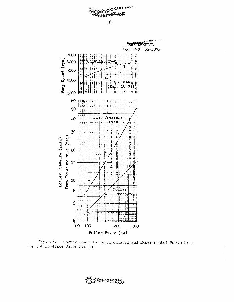
A comparison i s made i n Fig. 24 between IWS data and i t s calcu-
l a t e d counterpart . Tne TdS data was matched i n the v i c i n i t y of 3.0
kw per rod; a series of computer T U ~ S was then made with varying
b o i l e r power and the r e s u l t s compared a s shown i n the f igure , A s
can be seen, the agreement between experimental and ca lcu la ted values
of pump pressure r i s e and b o i l e r pressure i s exce l len t . The comparison
does not f a r e near ly so w e l l , however, i n the case of pump speed,
Possibly the discrepancy stems from a di f fe rence between the turbine-
p u p o v e r a l l e f f i c i e n c y determined from bench t e s t s and that; obtaining
with t h e u n i t i n s t a l l e d i n the t e s t loop. The computer program
c u r r e n t l y uses t he o r i g i n a l bench t e s t data f o r eff ic iency, whereas
t h e pump i n t h e t es t r i g h a s been reworked t o reduce the load on
the t h r u s t bearing.
Detailed d i g i t a l coxputer ca lcu la t ions have shown t h a t t he bas ic
cont ro l concepts f o r system operation as se-t f o r t h i n the f irst por t ion
of Ynis repor t a r e sound, and t h a t the system can be proportioned and
the various components matched SQ t h a t the only c o n t r o l a c t i o n required
over a wide range of powers i s c o n t r o l of t he heat input t o t he b o i l e r .
Experience with system mocku-ps operating both with water and wit'n
potassium has shown t h a t t he systems operate e s s e n t i a l l y as predicted
by d i g i t a l computer ca l cu la t ions . For example, t he computer r e s u l t s
n
d rn (d
p1 v
g 15 E rn rn
10
8
4
Fj g. 24. Comparison between Calculated and Experimental Parmeters f o r Intexmedi-ate Water System.
39
show t h a t , over a wide operat ing range, t h e output of t h e f ree- turb ine-
dr iven c e n t r i f u g a l feed pump exceeds t h a t required, thus ensuring con-
trol of t h e l i q u i d inventory d i s t r i b u t i o n through c a v i t a t i o n i n t h e
feed pump. The experimental systems t e s t e d y i e l d t h e same conclusion.
A detaiJ.ed ana lys i s of t h e flow and pressure d i s t r i b u t i o n through-
out t h e MF'RE system has been c a r r i e d out with experimental component
c h a r a c t e r i s t i c s u t i l i z e d wherever ava i l ab le . The r e s u l t i n g d i g i t a l
computer program has provided a ready means for eva lua t ing t h e e f f e c t s
of changes i n component c h a r a c t e r i s t i c s and opera t ing condi t ions . The
u t i l i t y of any proposed system modif icat ion can be evaluated quickly
and at m i n i m u m expense with a d i g i t a l computer ca l cu la t ion .
The d i g i t a l computer code has been u s e f u l i n the proport ioning of
experimental systems i n order t o achieve t h e des i red operat ing charac-
t e r i s t i c s . The je t pump proport ions f o r t h e IPS were so determined;
t h e system has operated q u i t e s a t i s f a c t o r i l y with these pumps.
An es sen%ia l p a r t of t h e o v e r a l l computational scheme i s the
a b i l i t y to determine pressure drop during bo i l ing . The two-phase
pressure drop equat ions developed i n t h i s r epor t , while perhaps ad hoc,
provide a r e l i a b l e means for pred ic t ing r e a c t o r core presslire drops.


APPEI!JDICES

43
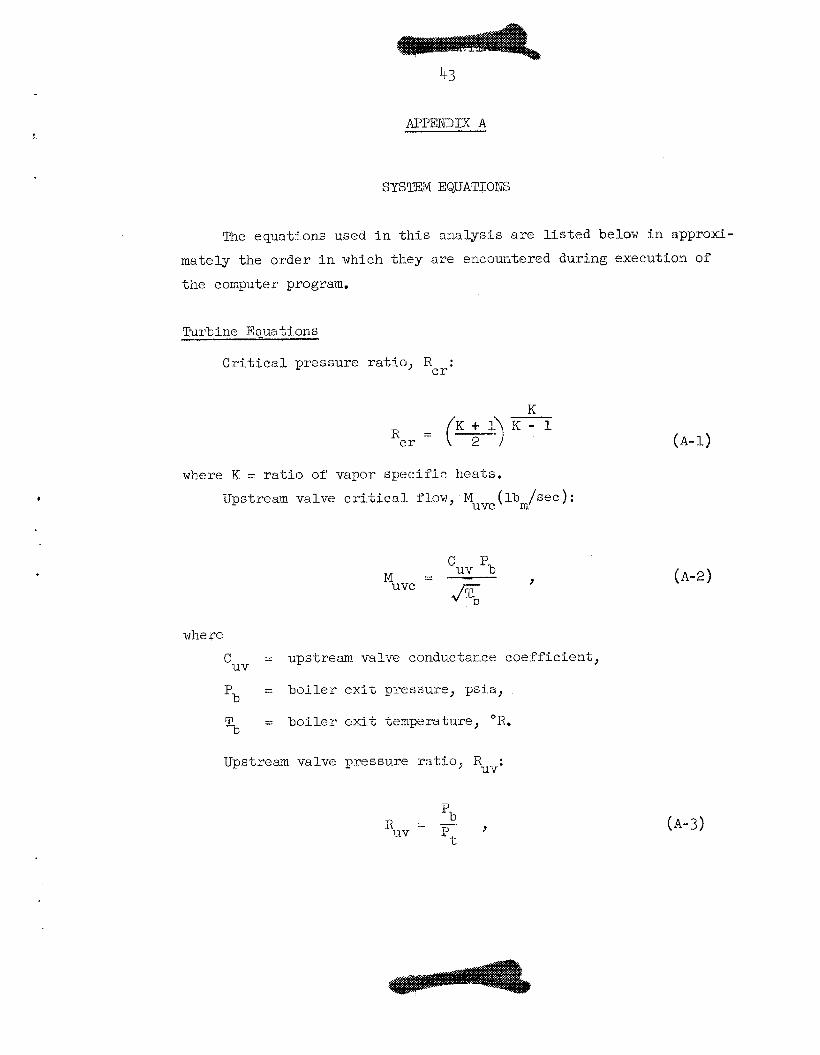
APPENDIX A
.
The equations used i n t h i s ana lys i s a r e l i s t e d below i n approxi-
mately the order i n which they a re encountered dur ins execution of
the computer program.
Turbine Equations
C r i t i c a l pressure r a t i o , R : c r
where K = r a t i o of vapor s p e c i f i c heats .
Upstream valve c r i t i c a l flow, Muvc ( lbm/see ) :
%V pb J
where
C = upstream valve conductance coef f ic ien t ,
Pb =: b o i l e r e x i t pressure, ps ia ,
1;3 = b o i l e r e x i t temperature, O R .
UV
RUV: Upstream valve pressure r a t i o ,
, 'b R = - uv IJt (A-3)
where
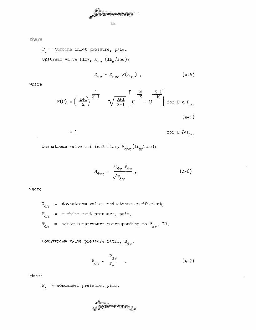
P = tu rb ine i n l e t pressure, p s i a ,
Upstream valve flow, M ( lbm/sec) :
t
uv
where
1- K- 1 -
F(U) = ( y) 2
4s [u u f o r U < Rcr
(A-5)
= 1 f o r U > R c r
Downstream valve c r i t i c a l flow, Mdvc ( lbm/sec ) :
where
= downstream valve conductance coe f f i c i en t , ‘dv
Pdv = tu rb ine e x i t pressure, psi.a,
n = vapor temperature corresponding t o P OR. ‘dv dv’
Downstream valve pressure r a t i o , R : dv
’d v (A-7)
where
P = condenser pressure, ps ia . C
45
Downstream valve flow, Mdv(l.bm/~ec) :
where F ( R ) i s as previously defined. dv
Continuity requirement:
- Mdv - Muv '
dv' by i t e r a t i o n on P
2 Joule-Thornson coe f f i c i en t , I: J T (OR-in. /lbr):
f o r l i g h t water,
1 -- 3 . CJT = 2.12 P
f o r potassium,
0. $3 CJT = 79.0 P-
where P i s the i n i t i a l pressure for an i sen tha lp ic expansion.
Turbine i n l e t temperature, Tt ( O R ) :
(A-9)
(A- 10a )
(A- lob )
( A - 1 1 )
K + l - K - 1 At Pt P (A-12)
4- M =
t c
where 2
= 32.174 (lbm/lbf) ( f t / s ec ) 9 gc
*t
R = gas constant, f t -1bf / lbm- 'R , 2
= turbine-nozzle t h r o a t area, i n .
1
46
Turbine pressure r a t i o , . Rt'
Turbine flow, M (lbm/sec): t
M = MJ- P(Rt) > t LC
where F(Rt) i s a s prevrously defined by Eq. (A-5).
Continuity requirement :
M = M t uv
t' by i t e r a t i o n on P
Bypass valve flow, M (lbm/sec): V
where
C = bypass valve conductance c o e f f i c i e n t , V
J e t -Dmp Equations
No : Maximum pressure r a t i o ,
b ( 2 - l .3b) N = o 1.1 - b ( 2 - 1-35)
where b = nozzle-to-throat a r ea r a t i o .
OO : Maxirnui flow r a t i o ,
( A - 1 3 )
(A-14)
(A-15)
(A-16)
(A-17)
47
Pressure ratio, N:
9 Ni N = 1.1 - Ni
where
= o for @ > Qo
( A - 2 0 )
Bo i l e r Equations
Feed-heater flow, hot side, % ( lbm/sec):
, M = - 'f 'b
fJ5';;- where
C = feed-heater conductance coefficient.
T o t a l vapor flow, M (lbm/sec):
f
b
( A - 2 1 )
( A - 2 2 )

48
Power required, p (kv):
p = 1.05487 H (1% - Mf) + Cp % (Tb-Tc)l , (A-23) I fg where
H = l a t e n t heat , Btu/lbm , fi3
C = l i qu id s p e c i f i c heat , Btu/lbm - O R , P
T = condensa-te temperature, "K . c
Total flow i.nto b o i l e r , M ( lbm/sec):
Mb M = - x '
where
x = vapor qua l i ty .
Feed-heater e x i t temperature, cold s ide , Tf (OR) :
Boi le r i n l e t temperature, Ti ( O R ) :
T. = x Te + (1 - X ) Tb . 1
(A-24)
(A-25)
(A-26)
Preheater length, L ( i n . ) : P
L = 1.05487 C- ('Ib - Ti) M Ih/p , (A-27) P P
where
L = heated length iil boiler . matrix, i n , n
49 . Boil ing Lengta, % ( in . ) :
% = I C L P
Boiler pressure drop, mb ( P s i > :
(A-28)
where
Nf, ma, and 4Ph a r e the f r i c t i o n , acce le ra t ion , and s t a t i c head
compopents of the b o i l e r pressure drop computed as shown i n Appendix B.
Boi le r J e t - Sump Equations
Flow r a t i o , . Ob*
1 - x - - 'b X
Pressure r a t i o , Nb:
N = 1.1 - Nlb 9 b
where N i s defined by Eq. (A-20). lb
Side p o r t pressure, Psb ( p s i a ) :
where 2
g = Local g r a v i t a t i o n a l acce lera t ion , f / sec ,
(A-30)
(A-32)
% = s t a t i c head from vapor separator , in . ,
v = l i q u i d s p e c i f i c volume, f t 3 /lb. ro
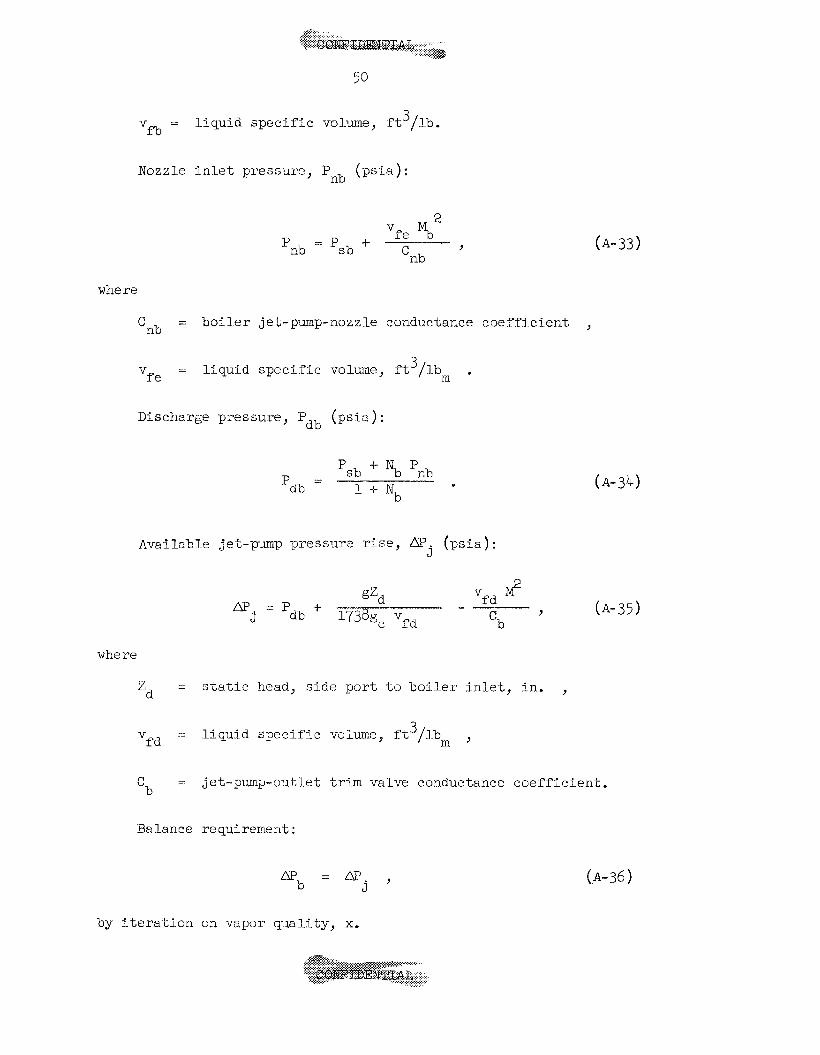
Nozzle i n k t pres sure, pLlb (ps i a ) :
2 vfe Mb
4- nb 'nb 'sb ?
where
= b o i l e r j e t -pump- nozz l e conductance c o e f f i c i e n t , crib = l i q u i d s p e c i f i c volume, f t 3 /lbm .
f e v
Discharge pressure, P ( p s i a ) : ab
+ N P - 'sb b nb 'dh - 1 -+ Nb
Available jet-pum7 pi-essur? r ise , m. ( p i a ) : J
v M ? gzd f d m . = p 9
J db 1738gc Vfd 'b ,
where
= s t a t i c head, s i d e p o r t $0 b o i l e r i n l e t , i n . 'd
(A- 3°C)
(A-35)
9
-: l i q u i d s p e c i f i c voluxe, f t3/ lbm , f d
V
= jet-pumpoutl .et t r i m valve conductance c o e f f i c i e n t . 'b
Balance requirement:
(A-36)
by i t e r a t i o n on vapor qua l i t y , x.
5 1
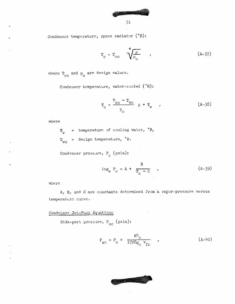
Condenser temperature, space radiator ( O R ) :
Tc - - Tco * , where Tco and p are design values.
0
Condenser temperature, water-cooled ( OR) :
U
where
= temperature of coding water, O R ,
= design temperature, OR.
TW
Two
Condenser pressure, P c (psia) :
B
T c - C ’ log, P = A + c
(A-37)
(A-38)
(A-39)
where
A, B, and C are constants determined from a vapor-pressure versus
temperature curve.
Condenser Jet-Pump Equations
Side-port pressure, (psia) : psc
(A-40)
.... .. . .. .. . . . . . . . . . .:.:.:. >;.. . . . . . . . . . . . . . . . . . . . . . . . . - ..:.:..:
52
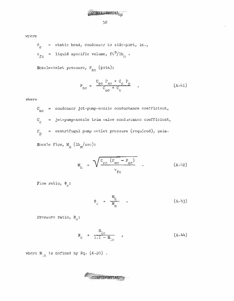
where
Zc = static head, condenser to side-port, in.,
V = liquid specific volume, ft3/lb . fc m
Nozzle-inlet pressure, 'ne (psia):
P + C C ? - 'ne sc P
'nc + ' c 'ne -
where
= condenser jet-pump-nozzle conductance coefficient, 'nc
Cc = jet-pump-nozzle trim valve condixtance coefficient,
P = centrifugal pm-p outlet pressure (required), psia. P
Nozzle flQw, Mn (lb /see): m
'fc
Flow ratio, iD : C
Pressure ratio, N : c
- N I C
l.l - N 9
Lc *e -
where N is defined by Eq. (A-20) . IC
(A-41)
(A-42)
(A-43)
(A-44)
53
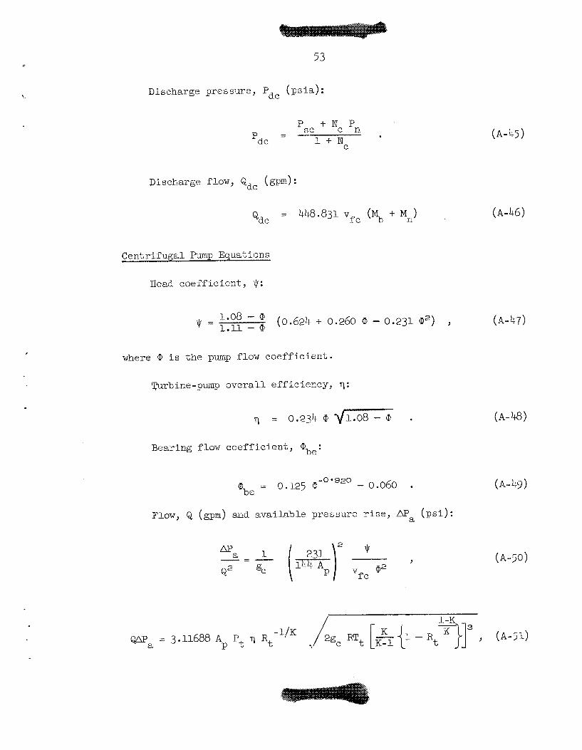
Discharge pre s sure , 'de (psia):
- - ' s c + 'c 'n 'de - 1 f- Ne
Discharge flow, Qdc (gpm):
Qdc = 448.831 vfc (MI, + Mil)
(A-45)
(A-46)
Centr i fuga l Pump Equations
Head coef f ic ien t , , q :
l*O8 - ' (0.624 + 0.260 a - 0.231 Q,Z) , (A-47) = 1.11 - 0
where i s t h e pump flow coef f ic i .en t .
m r b ine -pump o v e r a l l e f f i c i ency 11 :
(A-48) r l = 0.234 @ q- . Bearing flow c o e f f i c i e n t :
(A-49) -0 '920 = 0.125 Q, - 0.060 .
'be
Flow, Q (gpm) and ava i l ab le pressure r i s e , aPa ( p s i ) :
2 ? - = - 1 (-e) Y
v Q2 fc Q2 %C
(A-50)
54
where
A = pump d i f f u s e r t h r o a t area, in." P
Bearing flow, &be (gpm) :
Pump i n l e t f l o w required, Q. (gpm): 1.
Qi = &b e + Qdc
Balance requirement:
Q = Q i ,
by i t e rnk ion on @.
Pump speed, N (rpm):
where
D = pulp impeller t i p diameter, i n . I?
Required pimp pressure rise, Dr (ps i ) :
(A-52)
(A-53)
(A-54)
(A-55)
(A-56)
55
where \.
= puap discharge trim valve conductance c o e f f i c i e n t . cP
Cavi ta t ion coe f f i c i en t , Ccav:
(A-57)

57
APPENDIX B
TWO-PHASE PRESSURE: DROP EQUATIONS
I n i t i a l versions of the system program used Owensr23 method f o r
computing pressure drop i n the bo i l e r .
Intermediate Water System became avai lable , it was found t h a t the
pressure drops were being overestimated by a f a c t o r of" roughly 2 t o 3.
Wnile p a r t of t h i s discrepancy undoubtedly stems from the f a c t t h a t
Owens' procedure i s b a s i c a l l y a homogeneous ca lcu lz t ion , h i s success
i n c o r r e l a t i n g the Schrock and G r 0 ~ s m s . n ~ ~ da ta i n d i c a t e s t h a t t h i s i s
not t he whole s tory. A homogeneous c a l c u l a t i o n overestimates the two-
phase s p e c i f i c volume and, hence, both the a c c e l e r a t i o n and f r i c t i o n
components, while the s t a t i c head cont r ibu t ion i s underestimated.
These l a t t e r two e r r o r s a re a t l e a s t p a r t i a l l y compensating, so t h a t
agreement (or the lack of i t) may wel l depend on the proportion of
a c c e l e r a t i o n t o o v e r a l l pressure drop. This conclusion i s rendered
more p laus ib le by the f a c t s t h a t i n the Schrock and Grossman data,
which cor re la ted well, the ucce lera t lon component was a t h i r d or l e s s
of the t o t a l , whereas i n the TWS data, which cor re la ted poorly, the
a c c e l e r a t i o n drop c o n s t i t u t e s 60 t o 7 6 of the t o t a l .
However, when data" from the
Homogeneous flow i s a f i rs t order approximation ( t o the a c t u a l
f low) i n which s l i p i s assumed t o be ( a ) constant and (b ) equal t o one
f o r a l l pressures and qua l i t i e s . If t h i s l a t t e r r e s t r i c t i o n i s
relaxed t o the ex ten t of allowing the s l i p to be a funct ion of pressure
and, hence, of s p e c i f i c volume r r t i o , an approximation of penultimate
s i m p l i c i t y i s obtaiged. This approximation will be used i n what
follows i n order t o match the observed DE pressure drops.
shows the j u s t i f i c a t i o n f o r t h i s s tep . The data a r e those of Sher
f o r steam and water a t 14.7 ps ia i n v e r t i c a l flow with heat addition.
The superimposed curves were computed from the r e l a t i o n between void
f r a c t i o n and q u a l i t y a t constant s l i p r a t i o given by Eq. (B-3). can be seen, a r a t h e r narrow range of s l i p s u f f i c e s t o bracket t he
data. I n f a c t , t he curve f o r a s l i p r a t i o of f i v e f i t s about as wel l
a s t'ne data j u s t i f y .
Figure 16 19
As
. . . . . .
50
Preheat ing Sec t ion Pressure Drop
For t he f r i c t i o n a l component,
where
f = single-phase f r i c t i o n f ac to r ,
2 G = mass flow pe r u n i t a r e s , YO / sec- f t ,
D = equivalent di.ameter of flow passage, i n .
m
e
For the s t a t i c head component,
The acce le ra t ion component r e s u l t i n g from s p e c i f i c volume changes
i n the preheat ing sec t ion i s extremely small and w i l l be neglected.
Boi l inn Sect ion Pressure Dror,
From cont inui ty and the d e f i n i t i o n of qua l i t y , t he void f r ac t ion ,
a, may be expressed a s
where
1
1 + g s a = 1 . - x ,
S = s l i p r a t i o = vapor vel-ocity/l iquid ve loc i ty = V /V i3 f’
59
v = vapor s p e c i f i c volume, . g
E x i t qua l i ty , xeJ i s found from
For a l i n e a r v a r i a t i o n with heated length, t he qua l i ty , x, is
given by
J xeL
T-h - Lp x =
where
L = dis tance along heated length from s t a r t of bo i l ing , in .
The mixture dens i ty a t any point , p , may then be r igorously
defined by
1 - a p = - a + - . f
V v €3
The mixture s p e c i f i c volume, v, and p are r e l a t ed by
1 P
v = - . Tne f r i c t i o n a l component of the b o i l i n g pressure drop, APfb ,
may be expressed a s
From a momentum balance over the b o i l i n g length, we have
where
= I n i t i a l . l i q u i d ve loc i ty , f t / sec , 'fo
2 A = flow area, in .
The s t a t i c head component, APhb, i s given by
(B- 10)
Combining Ecjs. ( R - 3 ) through (B-IO) then y i e lds , for t he
f r i c t ioiia 1 component,
(B-11)
f o r the acce le ra t ion component,
[B-12)
and for t h e s t a t i c head component,
.... ............ ..... &,&=** .......... ............. ...... .,,... ........
61
Ove ra 11 Pres sure Drop
The o v e r a l l f r i c t i o n a l component i s given by
AP f = m f b + @fp ’
and t h e o v e r a l l a c c e l e r a t i o n component by
ab AP =AP a
The o v e r a l l s t a t i c head component i s
c9 = m h b + m . h hP
The t o t a l pressure drop i s then determined from
(B- 14)
(B-16)
which i s Eq. (A-29).
Nothing has been said, thus f a r , about how the s l i p r a t i o , so
freely used i n the above equations, i s t o be determined. Preliminary
appl ica t ion of the above pressure drop equations to experimental data
yielded, through an i t e r a t i v e procedure, values of s l i p r a t i o as a
.. .. .. . . . . . . . . . . . , . &w-. 62
fuiiction o f spec i fec volume r a t i o .
t he s lope of t he l i n e through t h e data agreed with Z i . v i ' ~ ~ ~ predic t ion ,
the magnitudes were s u b s t a n t i a l l y lower. Accordingly, a r e l a t i o n of the
form
A log-log p l o t showed t h a t , while
s = c & - - (B-18)
was assumed and the coef f ic ie r i t C was determined by a "best" f i t ( i n
the l e a s t squares sense) of ca lcu la ted to measured pressure drop.
Figure 17 shows t he r e s u l t i n g c o r r e l a t i o n for runs 301 through 334 of
INS data . The "best" value of C was found t o be 0 . l6 ,
A l l t h e data c o r r e l a t e t o about %25$; note, however, t h a t a sub-
s t a n t i a l share of t h i s s c a t t e r i s a sc r ibab le t o two out ly ing points .
If these two ou t lye r s were de le ted , t he remaining 32 po in t s would
c o r r e l a t e t o about Itl5$.
. . , . . . . . . . . . . . . . . ......
63
REFERENCES
t l 1. A, P. Fraas, e t al . , A Comparative Study of Fission-Reactor-Tdrbine- -- Generator Power Sources for Space Vehicles, '' USAEC Report ORNL-2150, Oak Ridge Nat ional Laboratory, September 1961.
A. E. Barbin and M. M. Yarosh, "An Analog Study of a Single-Loop Rankine Cycle System, '' National Laboratory, January 1966.
2, USAEC Report O R N L - T M - ~ ~ ~ ~ , Oak Ridge
3. M. M. Yarosh, " S t a b i l i t y and Control Charac t e r i s t i c s of E l e c t r i c a l l y Heated Test Rigs Designed t o Siniulate t h e MPRE Fluid System," USAX Report OXVL-TM- 1370, Oak Ridge National Laboratory, January 1966.
4, R. E, MacPherson, Jr., sild A. P. Fraas, "Potassium Rankine Cycle Operating Experience f o r the Medim Power Reactor Experiment, " presented a t t h e AIAA F i r s t Rankine Cycle Space Power Systems S p e c i a l i s t Conference, Cleveland, Ohio, October 1965.
f l 5. J. Foster , "The J@m Reactor Control Mechanism, presented a t t h e AIAA F i r s t Ra-nkine Cycle Space Power Systems S p e c i a l i s t Conference, Cleveland, Ohio, October 1965.
A. 14, Perry, "Status of MPRE Core Design," presented a t the AIAA F i . r s t Rankine Cycle Space Power S y s h n s S p e c i a l i s t Conference, Cleveland, Ohio, October 1965.
M. M. Yarosh, "Boiler S tudies F o r t he Medium Power Reactor Experi- ment," presented a t the AIAA F i r s t Rankine Cycle Space Power Systems S p e c i a l i s t Conference, Cleveland, Ohio, October 1965.
6.
7.
8. A. P. Fraas, "Design and Development Tests of Direct-Condensing Potassium Radiators, '' presented a t the AIAA F i r s t Rankine Cycle Space Power Systems S p e c i a l i s t Conference, Cleveland, Ohio, October 1965.
9. E., E. GiVerlie, Spaqe Power Program Semiannual Progress Report June 30, 1962, OmE3337, PP. 9-12.
10. M. E. LaVerrie, "Analysis of t he Hot Spot Problem i n the MFTW2" USAEC Report ORnTLTM-137l, Oak Ridge Nat ional Laboratory, January 1964.
11. A. P. Fraas Conditions, USAEC Report 0-WL CF-59-11-1, Oak Ridge National Laboratory, November 1961,
"Flow S t a b i l i t y i n Beat Transfer Matrices Under Boiling e 9
4 4
12.
13
14.
16.
17.
18.
1-9.
20.
21.
22.
23
2)+.
J. W. Michel and A. M. Perry, "Design Study of Boi l ing Potassium Reactors f o r Thema1 Outputs of 1 t o 30 Mw," 'IN-1365, Oak Ridge National Laboratory, January 1.966.
R. B. Korsmeyer, "Condensing Flow i n Finned, Tapered TUbes," USAEC Report OWL-TM-534, Oak Xidge Nat ional Laboratory, May 1, 1963.
USAEC Report ORNL
A. P. Fraas, "Survey of Operating Conditions and Requirements for Nuclear Reactor Turbine-Generator Space Power P lan t s f o r the 1970- 1985 Periods," Laboratory, January 1966.
USAEC Heport OR~TL-~T~I-1364, Oak Ridge National
A. P. Fraas ,"Effects of Power Output on Inventory and Flow D i s t r i - bu t ion through YPRE System, I'
Progr. Iiept. June 30, 1963, USAEC Eepcrt 0 ~ ~ ~ 3 4 8 9 , Oak Ridge pp. 12-25, Space Power Program Semiann.
Nat ional Laboratory.
M. E. LaVerne, M. M. Yarosh, and A. R. Rarbin, "System Flow D i s t r i - - I 1 bution, Stabil i ' iy, and Control, p. 13, Mediwn-Power Reactor Experi- ment Progr. Report September 30, 1963, USAEC Report OWL-3534, Oak Ridge Nat ional Laboretory a
C. S. Mayo and H. D. Ilinhardt, Test Report o f Steam-Turbine-Driven Pu~ip, Aeronutroiiic Divi-sion, Ford Motor Co. , March 6, 1963.
R. G. Cunnlngham, "Jet-EZlmp Tneory and Performance with Liquids of High Viscosity," Trans. ASME, 79: 1807-1820 (1957).
N. C. Sner, M. S. Thesi-s, Univ. of Minil., Minneapol.is (1955).
M. M. Yarosh, unpublished INS data . (To be published.)
C . J. Meisl and A. Shapiro, Thermodynamic P rope r t i e s o f Alka l i Metal Vapors and Mercury - 2nd Hyvision, November 9, 1960, Report ,960PBD358-A, F l i g h t Pro;)ill s ivn Labora tory Department, General E l e c t r i c Company, Cincinnat i , Ohio.
J, H. Keenan and F. G. Keyes, 'i"lerrnodynaivlic P rope r t i e s of Steam, 1st Ed., 1336. John Wiley a n d x n s , be., New York.
W. L. Owens, JT., sl'Two-Phase Pressure Gradient, Paper N. 41, pp. 363-368 i n P a r t JI,, Sec t ion A, In te r r ia t iona l Developrneiits i n Zeat Transfer, 1961 In te rna Lional Heat Transfer Conference, Aug. 28- Sept. I;, l m u l d e r , Colorado.
V. E. Schrock and L. M. Grossman, "Forced Convection Boiling Studies," Univ. of Gal-if. Tnstitu-Le of Engineering Research Report Ser ies , '73308 - UCX 2182, No. 2, November 1959.
25. S. M. Zivi, "Estimation of Steady-State Steam Void-Fraction by Trans.
ASME, Series C, Journa l of Heat Transfer, 86: 247-252 ( i m Means of t he Principle of Mininun Entropy Production, i t

INTERNAL DISTRIBUTION
1. G. 14. Adamson 2. S. E. Bea l l 3. H, C. Claiborne 4, F. L. Cu l l e r 5. 5. E. Cunningham 6. J. H, DeVan 7. J. Fos te r
8-27. A. P. Fraas 28. A. G. Grindel l 29. P. N. Haubenreich
31. S. I. Kaplaa 32* P. H. Kasten 33. R. B, Sorsmeyer 34. M. E. Lackey 35. M. E. LaVerne 36. M. I. Lundin 37. R. N. b o n 38. II. G. MacPherson 39. R. E, MacPherson 40. H. C, McCurdy 41. J, W. f i c h e 1
30. w. 0. H~TIIIS
42. 43 9
44. 45. 46. 47 48. 49 50. 51. 52 * 53 54. 55. 56 e
57 58
59-63. 61-62, 63-65.
66 e 67
A. J. Miller A. M. Perry G. Samuels H, W. Savage A, W. Savolainen J. L. Sco t t 0. L. Smith I, Spiewak A. Taboada D. B. Trauger A. M. Weinberg J. R, Weir, Jr. G. D, WM.tman J, V. Wilson M. M. Yarosh Gale Young J. Zasler Cen t ra l Research Library Y - 1 2 Document Reference Sect ion Labor a t o ry Re eo rd s Laboratory Records-Records Copy ORNL Patent Office
EXTERNAL DISTRIBUTION
68. 69. 70 71-
72-81. 82 83 84.
85-08. 89- 90 0
91. 92 *
93- 96 9
97 98 99- 100. 101, 102 I
C . H. Armbruster, Wright A i r Development Center, Dayton, Ohio D. Blancher, Lockheed, Burbank, Ca l i fo rn ia G. K, Dicker, ATE, Washington She rraa n Edwards , Lockheed, Sac rament 0, Ca li f ornia H, B. Finger, AEC, Washington Graham Hagey, NASA, Houston C a r l E. Johnson, AEG, Washington J. D. Lafleur, AEC, Washington Bernard Lubarsky, NASA, Lewis Research Center James Qmch, NASA, Washington Benjamin Pinkel, Rand Corp., Santa Monica, Cal i forn ia Fred Schulman, NASA, Washington Abe S i l v e r s t e i n , NASA, Lewis Research Center R. M. Spencer, AEC, Washington Jack S t e a m s , JPL, Pasadena, Ca l i fo rn ia H. J. Stewart , JPL, Pasadena, Ca l i fo rn ia G. C. Szego, IDA, Arlington, Virginia T. F. Widmer, GE, Valley Forge, Phlladelphia, Pennsylvania Gordon Woodcock, NASA, Huntsvl l le W. Woodward, NASA, Washington
68
103-117.
ll9-12O. Reactor Division, OR0
Division of Technical Information Extension (UTIE) 118. Research and Development Divisi-on, OR0