Embed Size (px)
Citation preview
Control and optimization of toolpath in metal cutting applications through the usage of computer aided instruments A. Del Prete1, D. Mazzotta1 and A. Anglani1 1University of Lecce, Department of Engineering Innovation, Lecce, [email protected], [email protected], [email protected].
Abstract In metal cutting application, the normal operative condition is made by the following steps: definition of the part program through dedicated software applications, its conversion in ISO format for the specific machine, “first time” part program execution, quality control of the obtained part on CMM, part program improvement and certification. The illustrated procedure “as is” does not allow to judge the process performances of the defined toolpath until the CMM operation results are available. Moreover, no suggestions are available how to improve it if defects are highlighted by the CMM operation. The authors’ attempt is to implement a specific methodology in order to ensure process performances improvements through the usage of dedicated computer aided tools. In the present work a numerical/experimental correlation is performed relatively to the used instruments thanks to an alternative CMM’s usage, as well as an alternative objective function is suggested in order to take into account the manufacturing quality aspect during the process optimization phase.
Keywords: Metal Cutting, Computer Aided Manufacturing, CMM, Quality.
1 INTRODUCTION The presented activity, as part of a larger project related to an aeronautical application of these methodology and tools, has allowed to practically verify the technical advantages obtained through the application of the proposed procedure on two physical examples given by: a test specimen made by an Aluminum Alloy and a Casing part made by nickel alloy (INCONEL 718). On the casing, the authors have tested the external mill operation, which presents a high level of complexity. Nowadays, in metal cutting applications, the “tape tryout” (TTO), the first attempt part program execution upon CNC machine tool, is a very difficult and expensive phase in terms of: process time, raw material and human resources [1]. During physical tryout it is necessary to verify the part program’s accuracy in terms of path and planned technological parameters (feed rate, rotations per minute, local engagement between tool and workpiece). It is usually essential to perform a continuous inspection of the machining operations having as result a quite frequent toolpath editing operations.
Most CAM software tools carry out a cutter location file (CLF) validation, CLF can be considered the toolpath before the post processing phase. This simulation offers a preliminary idea of the physical application because, it is totally disconnected from the machine tool and its numerical control. Any tool motion has to be kinematically checked during the first execution in particular the operator has to perform a step by step machining, turning off the rapid motions toolpath parts. Rapid motions for modern machine tools can easily reach speed values up to 50 m/min, for this reason they could be the cause, if they are not well designed, of high speed collisions with possible serious damages to workpiece and/or machine tools. TTO needed time and relative costs can be reduced through the employment of virtual manufacturing. Virtual manufacturing is an emerging technology which allows to represent real manufacturing operations with models and simulation. The manufacturing activities and processes are modelled before and sometimes in parallel with the real manufacturing operations in the real world. Comparisons of models with reality and various model maintenance are always necessary [2]. Virtual manufacturing is introduced into several CAM tools as additional utilities able to provide a kinematic inspection of machine tool motions. In particular, VERICUT® which is the application used in the present work, it is able to verify the tool motion generated from the post processor. These computer aided techniques, applied to machining simulation, ensure a good toolpath verification only in terms of proper path. Post processing phase, in this virtual environment, detects machined model features and possible collisions (rapid motions that cause contacts between tool and physical part, collision among machine tool components, etc.) [3]; no information is available about dynamic interactions (forces, residual stress, strain) among workpiece/tool/machine tool. Machined model creation involves an exact knowledge of the contact conditions existing between the tool model and the raw material model; this information allows the implementation of the optimization module able to find cutting conditions more useful in terms of cycle time reduction, tool wear and surfaces quality. The authors’ aim can be summarized in the following statements: experimental effectiveness demonstration of the new procedure, numerical/experimental good correlation through the application of the chosen software tools and definition of an alternative objective function for subsequent optimization phases.
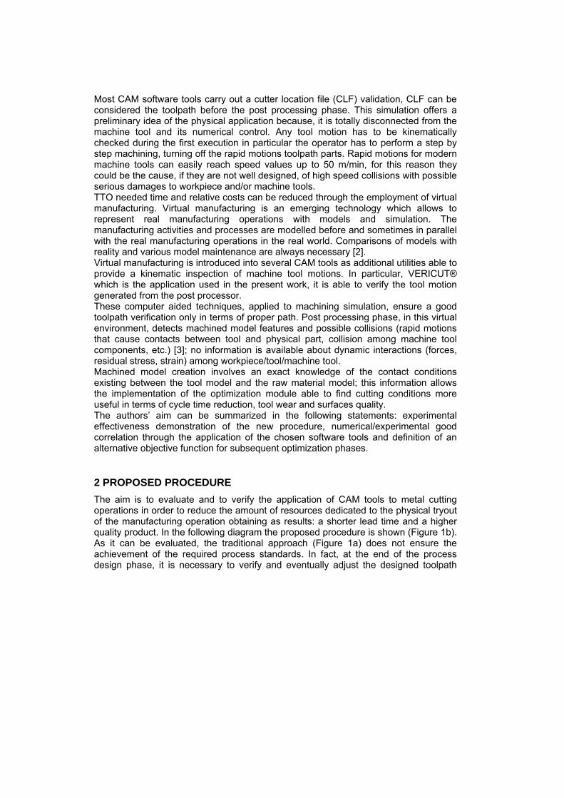
2 PROPOSED PROCEDURE The aim is to evaluate and to verify the application of CAM tools to metal cutting operations in order to reduce the amount of resources dedicated to the physical tryout of the manufacturing operation obtaining as results: a shorter lead time and a higher quality product. In the following diagram the proposed procedure is shown (Figure 1b). As it can be evaluated, the traditional approach (Figure 1a) does not ensure the achievement of the required process standards. In fact, at the end of the process design phase, it is necessary to verify and eventually adjust the designed toolpath
through a proper physical tryout followed by an appropriate inspection test. This is a very well-known and critical problem for industrial applications especially when raw material costs and complex toolpaths have a large influence.
Figure 1. (a) Traditional approach; (b) Proposed methodology.
The proposed procedure allows to avoid (Figure 1b) high levels of uncertainty during the physical tryout. Moreover, an optimization module can be used to improve the process design through a specific optimization set up. Lead time reduction is achieved thanks to the difference between the two highlighted steps in the previous diagram (red and green). Traditionally, the first worked part completion requires a large machining time due to the high uncertainty level of the operative phase; the usage of the proposed procedure ensures technical and operative advantages as it will be demonstrated.
CAM
Post processor
CAM
Toolpath definition
ISO file
Machine Tool
Verified and Optimized
First worked Part
CMM
Verified Part
Computer Aided Simulation environment Verified
ISO file
Optimized ISO file
CMM
Machine Tool
Worked Parts
Production
Machine Tool
First
worked Part
Post processor
ISO file
Toolpath definition
Machine Tool
Worked Parts
Production
Lead Time
b) a)
Verified Part
In order to validate the proposed procedure, several steps have been defined as it is reported below. In particular, steps from 1 to 7 contain the necessary action to perform a software tools validation regarding post processing and simulation phases, while steps from 8 to 14 include the required actions to give an experimental positive feedback.
1. Model 3D creation containing the machining features usually managed in operative environment;
2. Toolpath creation in CAD/CAM manufacturing module; 3. Post processor carrying out. The post processor is specific for
CAM/MACHINE/CNC (UG-NX/Mandelli Storm 1400/Siemens 840D in this specific case);
4. Simulation environment generation using VERICUT (Mandelli Storm 1400/Siemens 840D);
5. Process simulation in VERICUT; 6. Execution of the physical tryout (TTO); 7. Component inspection; 8. Casing model import in UG-NX (CAM environment); 9. Casing toolpath creation; 10. Casing Simulation in VERICUT; 11. Casing physical tryout (TTO) execution; 12. Performances evaluation; 13. Physical component inspection; 14. Data collection and analysis of the obtained results.
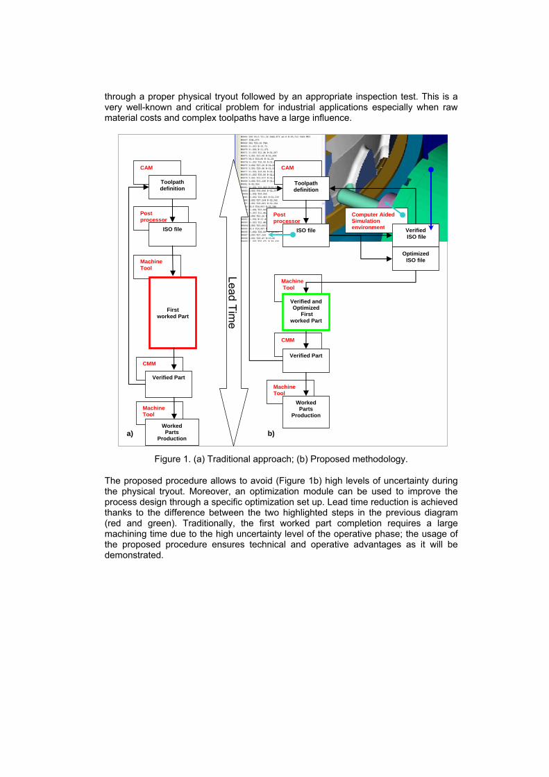
Consecutively, a summary of the focal points is given. After a creation of the 3D model (STEP 1) (Figure 2) [4] and toolpath definition (STEP 2-3) (CAM operations > Post Processing phase > Part Program) [5], the authors have created a specific virtual environment.
(by courtesy of AVIO S.p.A.)
Figure 2. Test case 3D model.
A kinematic model of the machine tool is reproduced by an elements tree; 3D models can be attached to elements in order to perform the collisions verification (*.mch file). Moreover, a virtual numerical control able to read the part program instructions has been developed (*.ctl file) (STEP 4) [6] like in the case of the physical numerical control.
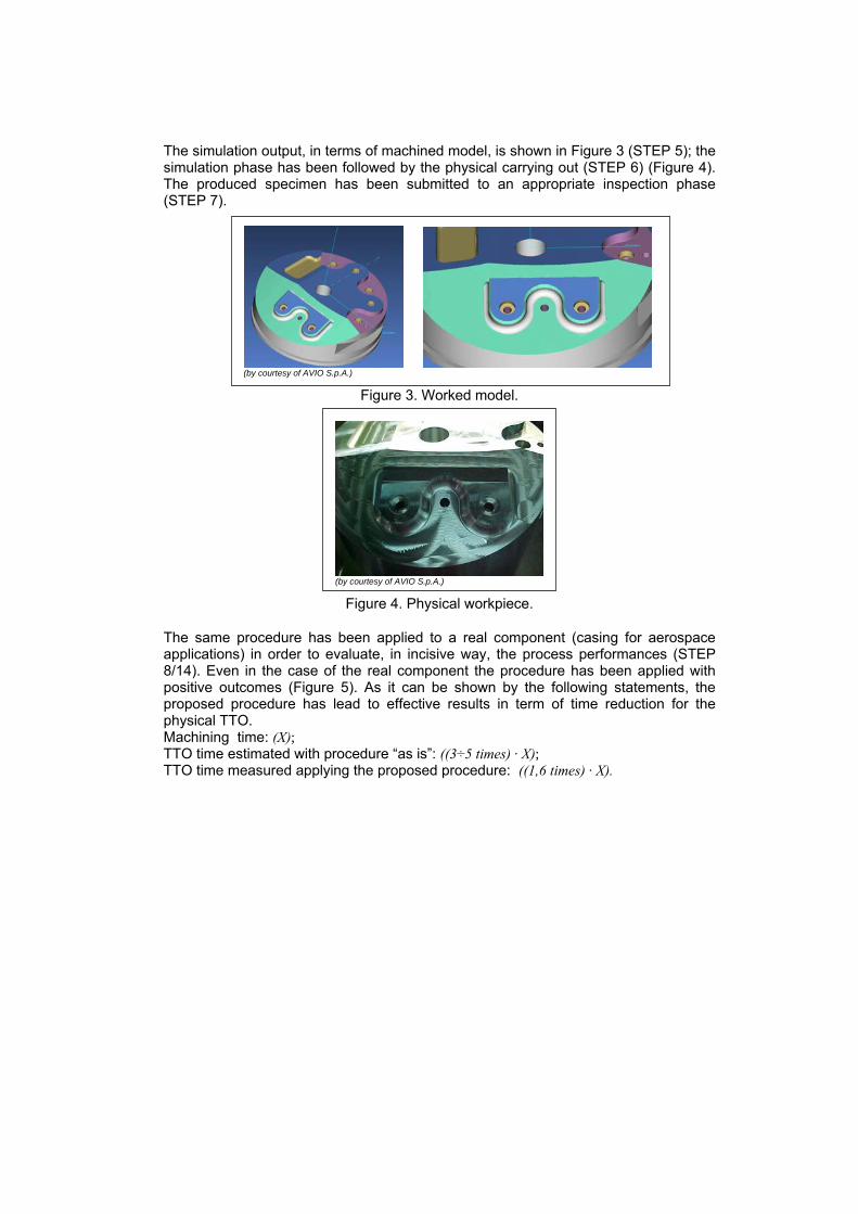
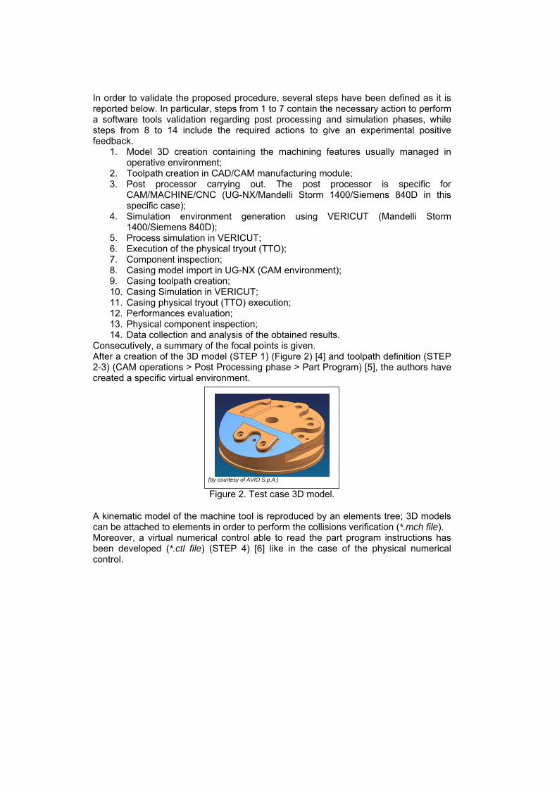
The simulation output, in terms of machined model, is shown in Figure 3 (STEP 5); the simulation phase has been followed by the physical carrying out (STEP 6) (Figure 4). The produced specimen has been submitted to an appropriate inspection phase (STEP 7).
(by courtesy of AVIO S.p.A.)
Figure 3. Worked model.
(by courtesy of AVIO S.p.A.)
Figure 4. Physical workpiece.
The same procedure has been applied to a real component (casing for aerospace applications) in order to evaluate, in incisive way, the process performances (STEP 8/14). Even in the case of the real component the procedure has been applied with positive outcomes (Figure 5). As it can be shown by the following statements, the proposed procedure has lead to effective results in term of time reduction for the physical TTO. Machining time: (X); TTO time estimated with procedure “as is”: ((3÷5 times) · X); TTO time measured applying the proposed procedure: ((1,6 times) · X).
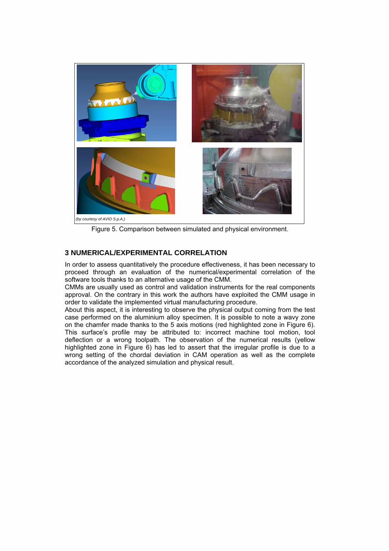
(by courtesy of AVIO S.p.A.) Figure 5. Comparison between simulated and physical environment.
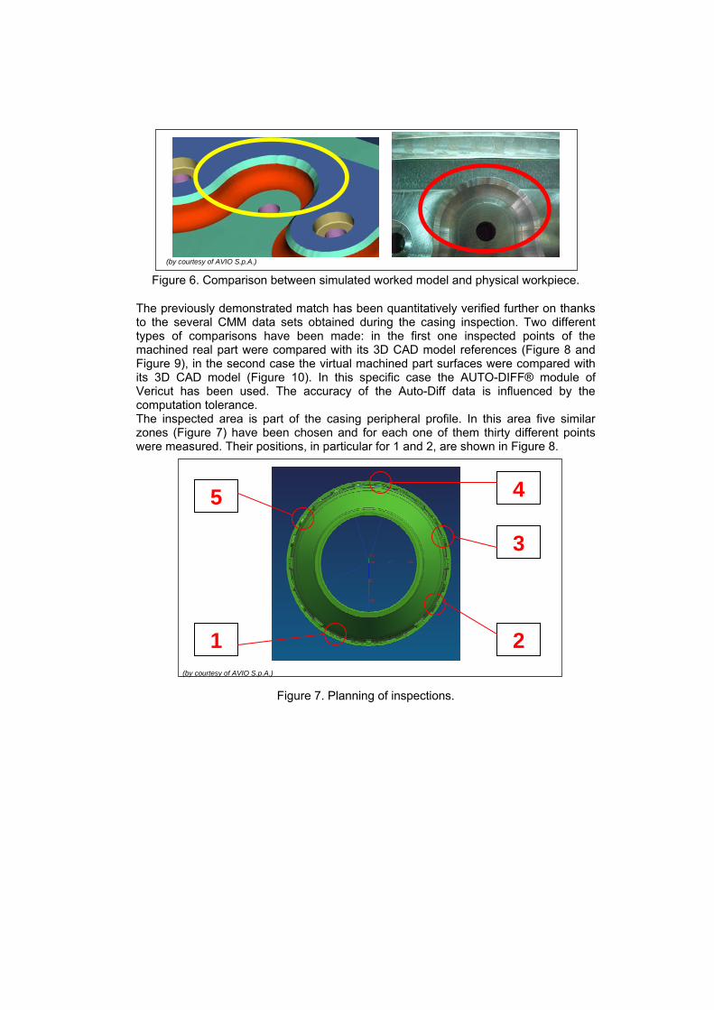
3 NUMERICAL/EXPERIMENTAL CORRELATION In order to assess quantitatively the procedure effectiveness, it has been necessary to proceed through an evaluation of the numerical/experimental correlation of the software tools thanks to an alternative usage of the CMM. CMMs are usually used as control and validation instruments for the real components approval. On the contrary in this work the authors have exploited the CMM usage in order to validate the implemented virtual manufacturing procedure. About this aspect, it is interesting to observe the physical output coming from the test case performed on the aluminium alloy specimen. It is possible to note a wavy zone on the chamfer made thanks to the 5 axis motions (red highlighted zone in Figure 6). This surface’s profile may be attributed to: incorrect machine tool motion, tool deflection or a wrong toolpath. The observation of the numerical results (yellow highlighted zone in Figure 6) has led to assert that the irregular profile is due to a wrong setting of the chordal deviation in CAM operation as well as the complete accordance of the analyzed simulation and physical result.
(by courtesy of AVIO S.p.A.)
Figure 6. Comparison between simulated worked model and physical workpiece.
The previously demonstrated match has been quantitatively verified further on thanks to the several CMM data sets obtained during the casing inspection. Two different types of comparisons have been made: in the first one inspected points of the machined real part were compared with its 3D CAD model references (Figure 8 and Figure 9), in the second case the virtual machined part surfaces were compared with its 3D CAD model (Figure 10). In this specific case the AUTO-DIFF® module of Vericut has been used. The accuracy of the Auto-Diff data is influenced by the computation tolerance. The inspected area is part of the casing peripheral profile. In this area five similar zones (Figure 7) have been chosen and for each one of them thirty different points were measured. Their positions, in particular for 1 and 2, are shown in Figure 8.
(by courtesy of AVIO S.p.A.)
Figure 7. Planning of inspections.
1 2
3
4 5
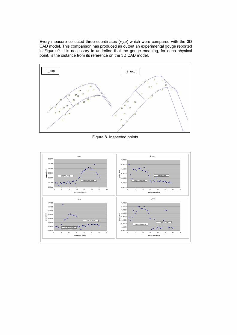
Every measure collected three coordinates (x,y,z) which were compared with the 3D CAD model. This comparison has produced as output an experimental gouge reported in Figure 9. It is necessary to underline that the gouge meaning, for each physical point, is the distance from its reference on the 3D CAD model.
Figure 8. Inspected points.
1_exp
0,00000
0,10000
0,20000
0,30000
0,40000
0,50000
0,60000
0 5 10 15 20 25 30 35
inspected points
goug
e [m
m]
CIRCULAR ZONE
LINEAR ZONE
2_exp
0,00000
0,10000
0,20000
0,30000
0,40000
0,50000
0,60000
0 5 10 15 20 25 30 35
inspected points
goug
e [m
m]
LINEAR ZONE
CIRCULAR ZONE
3_exp
0,00000
0,10000
0,20000
0,30000
0,40000
0,50000
0,60000
0,70000
0 5 10 15 20 25 30 35
inspected points
goug
e [m
m]
CIRCULAR ZONE
LINEAR ZONE
4_exp
0,00000
0,05000
0,10000
0,15000
0,20000
0,25000
0,30000
0,35000
0,40000
0 5 10 15 20 25 30 35
inspected points
goug
e [m
m]
LINEAR ZONECIRCULAR ZONE
1_exp 2_exp
5_exp
0,00000
0,05000
0,10000
0,15000
0,20000
0,25000
0,30000
0,35000
0,40000
0 5 10 15 20 25 30 35
inspected points
goug
e [m
m]
CIRCULAR ZONE
LINEAR ZONE
Figure 9. CMM Measured Differences between physical part and design model.
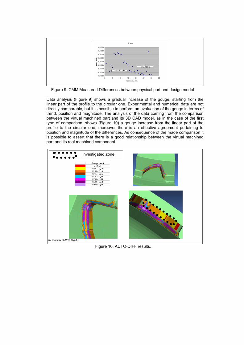
Data analysis (Figure 9) shows a gradual increase of the gouge, starting from the linear part of the profile to the circular one. Experimental and numerical data are not directly comparable, but it is possible to perform an evaluation of the gouge in terms of trend, position and magnitude. The analysis of the data coming from the comparison between the virtual machined part and its 3D CAD model, as in the case of the first type of comparison, shows (Figure 10) a gouge increase from the linear part of the profile to the circular one, moreover there is an effective agreement pertaining to position and magnitude of the differences. As consequence of the made comparison it is possible to assert that there is a good relationship between the virtual machined part and its real machined component.
(by courtesy of AVIO S.p.A.)
Figure 10. AUTO-DIFF results.
Investigated zone
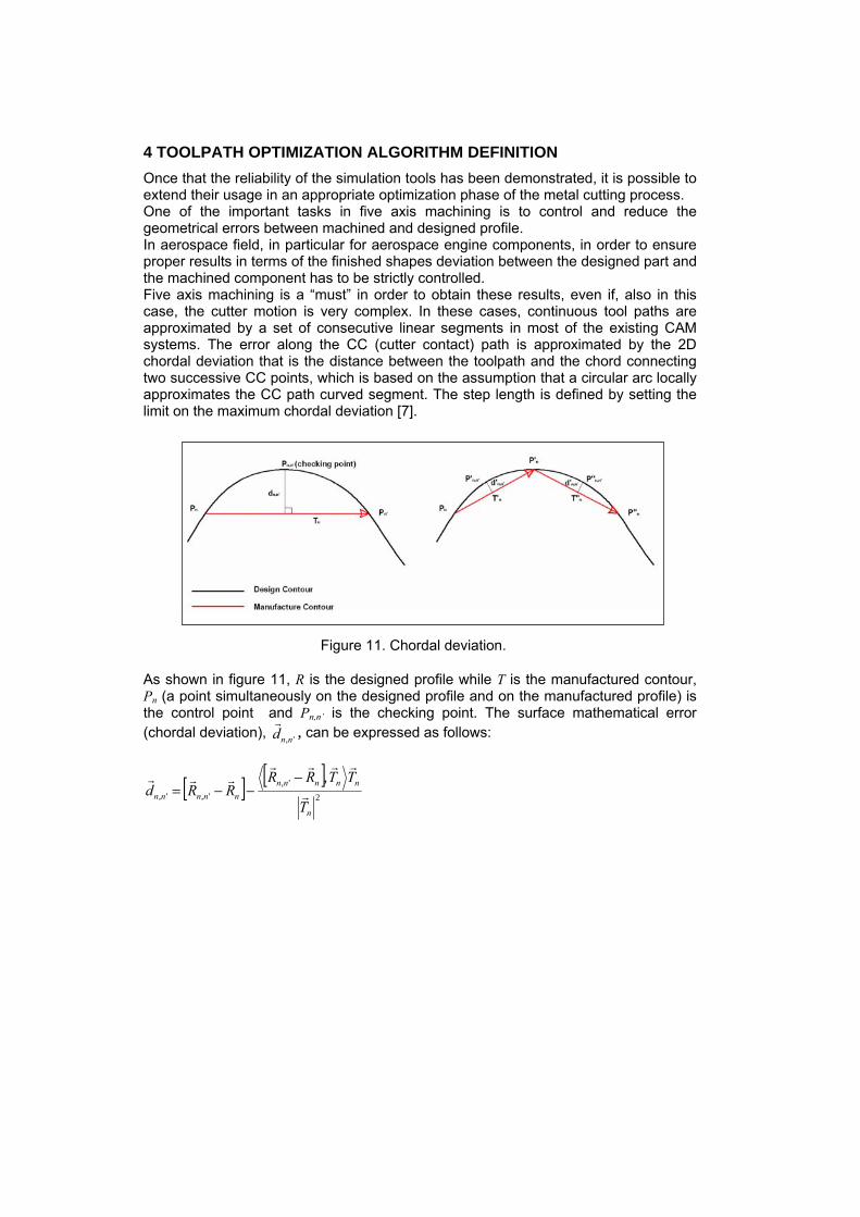
4 TOOLPATH OPTIMIZATION ALGORITHM DEFINITION Once that the reliability of the simulation tools has been demonstrated, it is possible to extend their usage in an appropriate optimization phase of the metal cutting process. One of the important tasks in five axis machining is to control and reduce the geometrical errors between machined and designed profile. In aerospace field, in particular for aerospace engine components, in order to ensure proper results in terms of the finished shapes deviation between the designed part and the machined component has to be strictly controlled. Five axis machining is a “must” in order to obtain these results, even if, also in this case, the cutter motion is very complex. In these cases, continuous tool paths are approximated by a set of consecutive linear segments in most of the existing CAM systems. The error along the CC (cutter contact) path is approximated by the 2D chordal deviation that is the distance between the toolpath and the chord connecting two successive CC points, which is based on the assumption that a circular arc locally approximates the CC path curved segment. The step length is defined by setting the limit on the maximum chordal deviation [7].
Figure 11. Chordal deviation.
As shown in figure 11, R is the designed profile while T is the manufactured contour, Pn (a point simultaneously on the designed profile and on the manufactured profile) is the control point and Pn,n’ is the checking point. The surface mathematical error (chordal deviation), ',nnd , can be expressed as follows:
[ ] [ ]2
',',',
,
n
nnnnnnnnnn
T
TTRRRRd
−−−=
Where nR is the position vector of the control point Pn, ',nnR is the position vector of
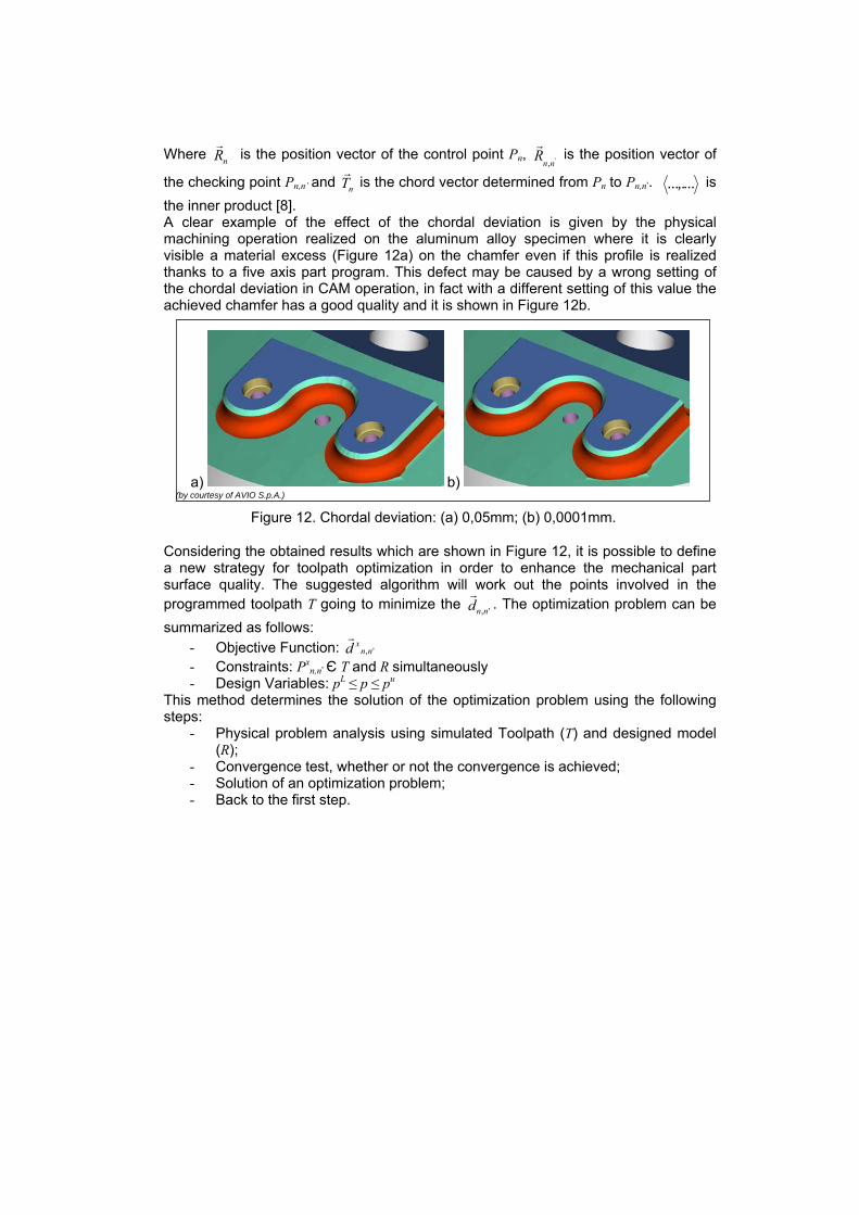
the checking point Pn,n’ and nT is the chord vector determined from Pn to Pn,n’. ...,.... is the inner product [8]. A clear example of the effect of the chordal deviation is given by the physical machining operation realized on the aluminum alloy specimen where it is clearly visible a material excess (Figure 12a) on the chamfer even if this profile is realized thanks to a five axis part program. This defect may be caused by a wrong setting of the chordal deviation in CAM operation, in fact with a different setting of this value the achieved chamfer has a good quality and it is shown in Figure 12b.
a) b) (by courtesy of AVIO S.p.A.)
Figure 12. Chordal deviation: (a) 0,05mm; (b) 0,0001mm.
Considering the obtained results which are shown in Figure 12, it is possible to define a new strategy for toolpath optimization in order to enhance the mechanical part surface quality. The suggested algorithm will work out the points involved in the programmed toolpath T going to minimize the ',nnd . The optimization problem can be summarized as follows:
- Objective Function: ',nnxd
- Constraints: Pxn,n’ Є T and R simultaneously
- Design Variables: pL ≤ p ≤ pu This method determines the solution of the optimization problem using the following steps:
- Physical problem analysis using simulated Toolpath (T) and designed model (R);
- Convergence test, whether or not the convergence is achieved; - Solution of an optimization problem; - Back to the first step.
5 CONCLUSIONS AND FURTHER DEVELOPMENTS Metal cutting complex phases, like TTO, can be sped up thanks to the proper usage of specific computer aided tools. The present work proposes, in accordance with experimental validation, an operative procedure for the virtual tryout of the designed toolpath for very complex cutting operative conditions. The obtained results have confirmed the approach validity and its utility in order to reduce execution time and possible dangerous collisions during the physical tryout. The good numerical-experimental correlation of the obtained results has allowed to investigate the application of the used tools for a further optimization phase in order to obtain high quality finished surfaces. Authors expect, in the near future, to test both numerically and experimentally the proposed optimization set up. In this way, the entire defined procedure will be fully validated allowing to certify a new approach to design complex toolpath part programs.
ACKNOWLEDGEMENTS This research has been supported by Avio Group, in particular the authors express their thanks to Castelluzzo G. (Avio Group Brindisi – experimental activities), Periale P. and Giglioli M. (Avio Group Rivalta – numerical activities) for their support on the developed activities.
REFERENCES [1] Kalpakjian S., Schmid S.R., 2001 4th edition. Manufacturing Processes for
Engineering Materials, Addison Wesley. [2] Lee W. B., Cheung C. F., Li J. G., 2001. Application of virtual manufacturing
in materials processing, Journal of Materials Processing Technology, 113, 416-423.
[3] Chen S. L., Wang W. T., 2001. Computer aided manufacturing technologies for centrifugal compressor impellers, Journal of Materials Processing Technology, 115, 284-293.
[4] Unigraphics Solutions ®, Modeling User Manual. [5] Unigraphics Solutions ®, Manufacturing User Manual. [6] VERICUT ®, User Documentation. [7] Lai X. et al., 2003. Geometrical Error Analysis and Control for 5-axis
Machining of Large sculptured surfaces, The International Journal of Advanced Manufacturing Technology, 21, 110-118.
[8] Lee R. S. and She C. H., 1998. Toolpath generation and error control method for multi-axis NC machining of spatial cam, Int. J. Mach. Tools Manufact. Vol. 38, No. 4, pp. 277-290.