Embed Size (px)
Citation preview
A1/1
Enc
lose
d st
arte
rs
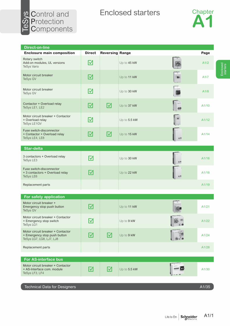
Direct-on-lineEnclosure main composition Direct Reversing Range Page
Rotary switchAdd-on modules, UL versions TeSys Vario
Up to 45 kW A1/2
Motor circuit breakerTeSys GV Up to 11 kW A1/7
Motor circuit breakerTeSys GV Up to 30 kW A1/8
Contactor + Overload relayTeSys LE1, LE2 Up to 37 kW A1/10
Motor circuit breaker + Contactor + Overload relayTeSys LE1GV
Up to 5.5 kW A1/12
Fuse switch-disconnector + Contactor + Overload relayTeSys LE4, LE8
Up to 15 kW A1/14
Star-delta
3 contactors + Overload relayTeSys LE3 Up to 30 kW A1/16
Fuse switch-disconnector + 3 contactors + Overload relayTeSys LE6
Up to 22 kW A1/18
Replacement parts A1/19
For safety applicationMotor circuit breaker +Emergency stop push buttonTeSys GV
Up to 11 kW A1/21
Motor circuit breaker + Contactor + Emergency stop switchTeSys LG1
Up to 9 kW A1/22
Motor circuit breaker + Contactor + Emergency stop push buttonTeSys LG7, LG8, LJ7, LJ8
Up to 9 kW A1/24
Replacement parts A1/28
For AS-interface busMotor circuit breaker + Contactor + AS-Interface com. moduleTeSys LF3, LF4
Up to 5.5 kW A1/30
Technical Data for Designers A1/35
TeS
ys Control and Protection Components
Enclosed starters Chapter
A1
A1/2
Enc
lose
d st
arte
rsReferences - Direct-on-line
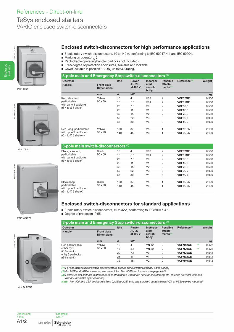
TeSys enclosed startersVARIO enclosed switch-disconnectors
Enclosed switch-disconnectors for high performance applications b 3-pole rotary switch-disconnectors, 10 to 140 A, conforming to IEC 60947-4-1 and IEC 60204.
b Marking on operator O .b Padlockable operating handle (padlocks not included).b IP 65 degree of protection enclosures, sealable and lockable.
b Cover lockable in position “I” (ON) up to 63 A rating.
3-pole main and Emergency Stop switch-disconnectors (1)
Operator lthe Power AC-23 at 400 V
Incorpor- ated switch body
Possible attach- ments (2)
Reference (3) Weight Handle Front plate
Dimensions
mm A kW kgRed, standard, padlockable with up to 3 padlocks(Ø 4 to Ø 8 shank)
Yellow60 x 60
10 4 V02 2 VCF02GE 0.50016 5.5 V01 2 VCF01GE 0.50020 7.5 V0 2 VCF0GE 0.50025 11 V1 2 VCF1GE 0.50032 15 V2 2 VCF2GE 0.50050 22 V3 3 VCF3GE 0.93063 30 V4 3 VCF4GE 0.930
Red, long, padlockable with up to 3 padlocks (Ø 4 to Ø 8 shanks)
Yellow90 x 90
100 37 V5 1 VCF5GEN 2.190140 45 V6 1 VCF6GEN 2.190
3-pole main switch-disconnectors (1)
Black, standard, padlockable with up to 3 padlocks(Ø 4 to Ø 8 shank)
Black60 x 60
10 4 V02 2 VBF02GE 0.50016 5.5 V01 2 VBF01GE 0.50020 7.5 V0 2 VBF0GE 0.50025 11 V1 2 VBF1GE 0.50032 15 V2 2 VBF2GE 0.50050 22 V3 3 VBF3GE 0.93063 30 V4 3 VBF4GE 0.930
Black, long, padlockable with up to 3 padlocks (Ø 4 to Ø 8 shank)
Black90 x 90
100 37 V5 1 VBF5GEN 2.190140 45 V6 1 VBF6GEN 2.190
Enclosed switch-disconnectors for standard applicationsb 3-pole rotary switch-disconnectors, 10 to 32 A, conforming to IEC 60947-4-1.b Degree of protection IP 55.
3-pole main and Emergency Stop switch-disconnectors (1)
Operator lthe Power AC-23 at 400 V
Incorpor- ated switch body
Possible attach- ments (2)
Reference (3) Weight Handle Front plate
Dimensions
mm A kW kgRed padlockable, either by 1 (Ø 8 shank) or by 3 padlocks (Ø 6 shank)
Yellow60 x 60
10 4 VN 12 2 VCFN12GE (2) 0.42216 5.5 VN 20 2 VCFN20GE (2) 0.42220 7.5 V0 0 VCFN25GE 0.51225 11 V1 0 VCFN32GE 0.51232 15 V2 0 VCFN40GE 0.512
(1)Forcharacteristicsofswitch-disconnectors,pleaseconsultyourRegionalSalesOffice.(2)ForVCFandVBFenclosures,seepageA1/4.ForVCFNenclosures,seepageA1/5.(3) Enclosure not suitable in atmosphere contaminated with harsh substances (detergents, chlorine solvents, ketones,
alcohol,aromatichydrocarbons).Note: ForVCFandVBFenclosuresfrom02GEto2GE,onlyoneauxiliarycontactblockVZ7orVZ20canbemounted.
VCFN12GE
9256
_SE_
L32.
eps
VCF 0GE
9348
_SE_
L27.
eps
VCF5GEN
PF51
1008
_SE_
L38.
eps
VCF 3GE
PG11
4001
_SE_
L38.e
ps
Dimensions:A1/36
Schemes:A1/37
A1/3
Enc
lose
d st
arte
rs
References - Direct-on-line
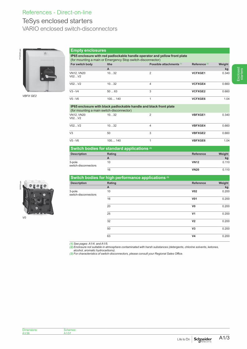
Empty enclosuresIP65 enclosure with red padlockable handle operator and yellow front plate (for mounting a main or Emergency Stop switch-disconnector)For switch body lthe Possible attachments (1) Reference (2) Weight
A kgVN12, VN20 V02…V2
10…32 2 VCFXGE1 0.340
V02…V2 10…32 4 VCFXGE4 0.660
V3 - V4 50 ... 63 3 VCFXGE2 0.660
V5 - V6 100.... 140 1 VCFXGE6 1.04
IP65 enclosure with black padlockable handle and black front plate (for mounting a main switch-disconnector)
VN12, VN20 V02…V2
10…32 2 VBFXGE1 0.340
V02…V2 10…32 4 VBFXGE4 0.660
V3 50 3 VBFXGE2 0.660
V5 - V6 100.... 140 1 VBFXGE6 1.04
Switch bodies for standard applications (3)
Description Rating Reference Weight A kg
3-pole switch-disconnectors
10 VN12 0.110
16 VN20 0.110
Switch bodies for high performance applications (3)
Description Rating Reference Weight A kg
3-pole switch-disconnectors
10 V02 0.200
16 V01 0.200
20 V0 0.200
25 V1 0.200
32 V2 0.200
50 V3 0.200
63 V4 0.200
(1)SeepagesA1/4.andA1/5.(2) Enclosure not suitable in atmosphere contaminated with harsh substances (detergents, chlorine solvents, ketones,
alcohol,aromatichydrocarbons).(3)Forcharacteristicsofswitch-disconnectors,pleaseconsultyourRegionalSalesOffice.
TeSys enclosed startersVARIO enclosed switch-disconnectors
V0
5805
50.e
ps
VBFX GE2
PF52
6300
.eps
Dimensions:A1/36
Schemes:A1/37
A1/4
Enc
lose
d st
arte
rsReferences - Direct-on-line
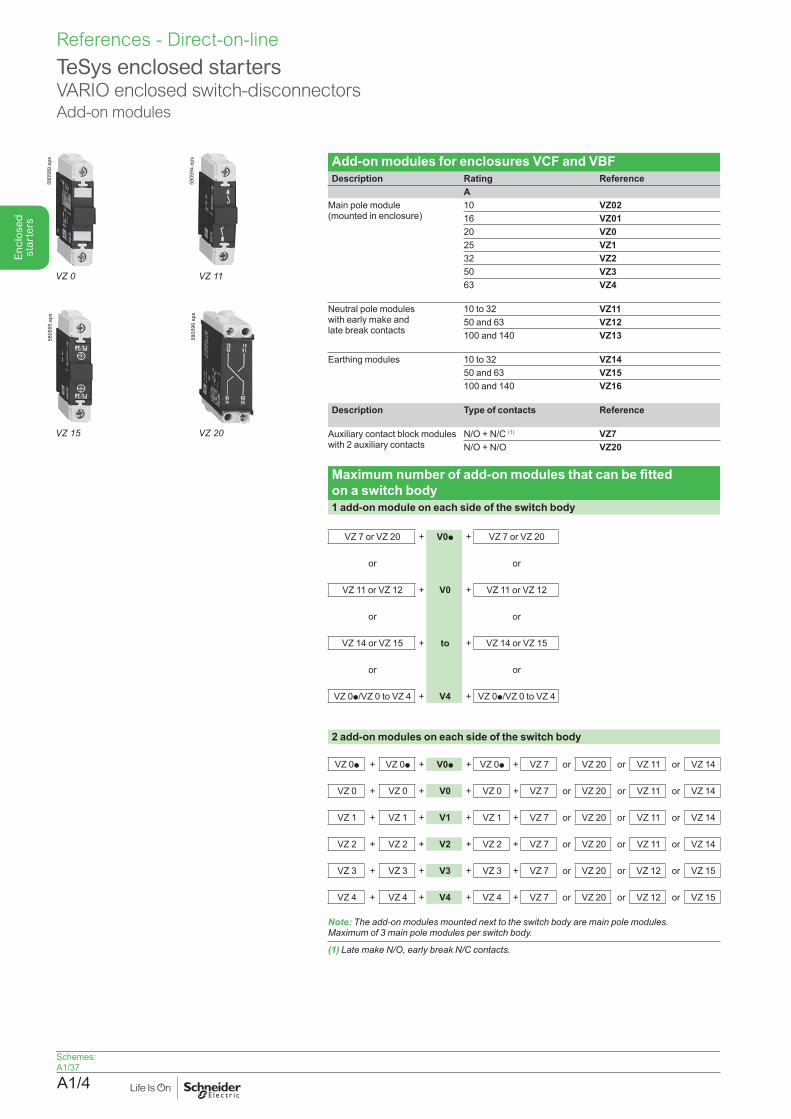
TeSys enclosed startersVARIO enclosed switch-disconnectorsAdd-on modules
Add-on modules for enclosures VCF and VBFDescription Rating Reference
AMain pole module (mounted in enclosure)
10 VZ0216 VZ0120 VZ025 VZ132 VZ250 VZ363 VZ4
Neutral pole modules with early make and late break contacts
10 to 32 VZ1150 and 63 VZ12100 and 140 VZ13
Earthing modules 10 to 32 VZ1450 and 63 VZ15100 and 140 VZ16
Description Type of contacts Reference
Auxiliary contact block modules with 2 auxiliary contacts
N/O + N/C (1) VZ7N/O + N/O VZ20
Maximum number of add-on modules that can be fitted on a switch body1 add-on module on each side of the switch body
VZ 7 or VZ 20 + V0p
V0
to
V4
+ VZ 7 or VZ 20
or or
VZ 11 or VZ 12 + + VZ 11 or VZ 12
or or
VZ 14 or VZ 15 + + VZ 14 or VZ 15
or or
VZ 0p/VZ 0 to VZ 4 + + VZ 0p/VZ 0 to VZ 4
2 add-on modules on each side of the switch body
VZ 0p + VZ 0p + V0p + VZ 0p + VZ 7 or VZ 20 or VZ 11 or VZ 14
VZ 0 + VZ 0 + V0 + VZ 0 + VZ 7 or VZ 20 or VZ 11 or VZ 14
VZ 1 + VZ 1 + V1 + VZ 1 + VZ 7 or VZ 20 or VZ 11 or VZ 14
VZ 2 + VZ 2 + V2 + VZ 2 + VZ 7 or VZ 20 or VZ 11 or VZ 14
VZ 3 + VZ 3 + V3 + VZ 3 + VZ 7 or VZ 20 or VZ 12 or VZ 15
VZ 4 + VZ 4 + V4 + VZ 4 + VZ 7 or VZ 20 or VZ 12 or VZ 15
Note: Theadd-onmodulesmountednexttotheswitchbodyaremainpolemodules. Maximumof3mainpolemodulesperswitchbody.
(1)LatemakeN/O,earlybreakN/Ccontacts.
VZ 0
5805
89.e
ps
VZ 11
5805
94.e
ps
VZ15
5805
95.e
ps
VZ 20
5805
96.e
ps
Schemes:A1/37
A1/5
Enc
lose
d st
arte
rs
References - Direct-on-line
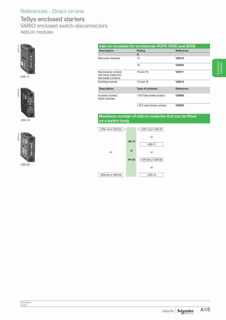
TeSys enclosed startersVARIO enclosed switch-disconnectorsAdd-on modules
Add-on modules for enclosures VCFN 12GE and 20GEDescription Rating Reference
AMain pole modules 10 VZN12
16 VZN20
Neutral pole module with early make and late break contacts
10 and 16 VZN11
Earthing module 10 and 16 VZN14
Description Type of contacts Reference
Auxiliary contact block modules
1 N/O late make contact VZN05
1 N/C early break contact VZN06
Maximum number of add-on modules that can be fitted on a switch body
VZN 12 or VZN 20 +
VN 12
or
VN 20
+ VZN 12 or VZN 20
or
VZN 11
or or
VZN 05 or VZN 06
or
VZN 05 or VZN 06 VZN 14
VZN11
5805
97.e
ps
VZN14
5805
98.e
ps
VZN05
5805
99.e
ps
Schemes:A1/37
A1/6
Enc
lose
d st
arte
rsReferences - Direct-on-line
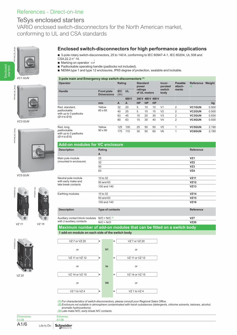
Enclosed switch-disconnectors for high performance applications b 3-pole rotary switch-disconnectors, 25 to 140 A, conforming to IEC 60947-4-1, IEC 60204, UL 508 and
CSA 22.2 n° 14. b Marking on operator b Padlockable operating handle (padlocks not included). b NEMA type 1 and type 12 enclosures, IP65 degree of protection, sealable and lockable.
3-pole main and Emergency stop switch-disconnectors (1)
Operator Rating Standard power ratingsof UL motors
Incor-porated switch body
Possible attach-ments
Reference (2)
Weight
Handle Front plateDimensions
IEC (Ith)
UL
600 V 240 V 480 V 600 Vmm A A HP HP HP kg
Red, standard, padlockable with up to 3 padlocks(Ø 4 to Ø 8)
Yellow 60 x 60
32 20 5 10 10 V1 2 VC1GUN 0.50040 25 5 10 15 V2 2 VC2GUN 0.50063 45 10 20 30 V3 2 VC3GUN 0.93080 63 15 30 40 V4 2 VC4GUN 0.930
Red, long, padlockable with up to 3 padlocks(Ø 4 to Ø 8)
Yellow 90 x 90
125 100 25 50 50 V5 1 VC5GUN 2.190175 115 30 50 60 V6 1 VC6GUN 2.190
Add-on modules for VC enclosureDescription Rating Reference
AMain pole module (mounted in enclosure)
25 VZ132 VZ250 VZ363 VZ4
Neutral pole module with early make and late break contacts
10 to 32 VZ1150 and 63 VZ12100 and 140 VZ13
Earthing modules 10 to 32 VZ1450 and 63 VZ15100 and 140 VZ16
Description Type of contacts Reference
Auxiliary contact block modules with 2 auxiliary contacts
N/O + N/C (3) VZ7N/O + N/O VZ20
Maximum number of add-on modules that can be fitted on a switch body1 add-on module on each side of the switch body
VZ 7 or VZ 20 + + VZ 7 or VZ 20
or V1 or
VZ 11 or VZ 12 + + VZ 11 or VZ 12
or to or
VZ 14 or VZ 15 + + VZ 14 or VZ 15
or V4 or
VZ 1 to VZ 4 + + VZ 1 to VZ 4
(1) Forcharacteristicsofswitch-disconnectors,pleaseconsultyourRegionalSalesOffice.(2) Enclosure not suitable in atmosphere contaminated with harsh substances (detergents, chlorine solvents, ketones, alcohol,
aromatichydrocarbons).(3) LatemakeN/O,earlybreakN/Ccontacts.
O
TeSys enclosed startersVARIO enclosed switch-disconnectors for the North American market, conforming to UL and CSA standards
VZ 11
PF56
9400
.eps
VZ15
PF56
9401
.eps
VZ 20
PF56
9402
.eps
VC1GUN
PF51
1002
_SE_
L20.
eps
VC3GUN
PF51
1004
_SE_
L26.
eps
VC5GUN
PF51
1008
_SE_
L34.
eps
Dimensions:A1/38
Schemes:A1/38
A1/7
Enc
lose
d st
arte
rs
References - Direct-on-line
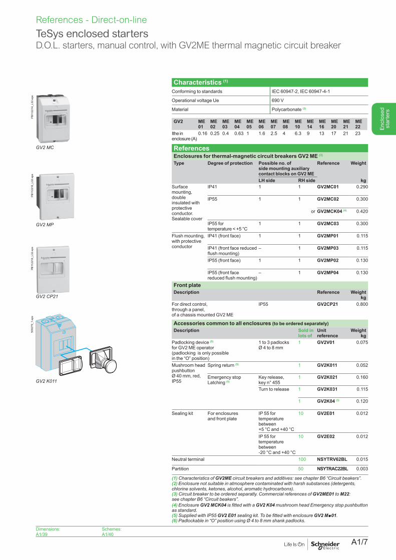
Characteristics (1)
Conforming to standards IEC 60947-2, IEC 60947-4-1
Operational voltage Ue 690 V
Material Polycarbonate (2)
GV2 ME 01
ME 02
ME 03
ME 04
ME 05
ME 06
ME 07
ME 08
ME 10
ME 14
ME 16
ME 20
ME 21
ME 22
Ithe in enclosure (A)
0.16 0.25 0.4 0.63 1 1.6 2.5 4 6.3 9 13 17 21 23
ReferencesEnclosures for thermal-magnetic circuit breakers GV2 ME (3)
Type Degree of protection Possible no. of side mounting auxiliary contact blocks on GV2 ME
Reference Weight
LH side RH side kgSurface mounting, double insulated with protective conductor. Sealable cover
IP41 1 1 GV2MC01 0.290
IP55 1 1 GV2MC02 0.300
or GV2MCK04 (4) 0.420
IP55 for temperature < +5 °C
1 1 GV2MC03 0.300
Flush mounting, with protective conductor
IP41 (front face) 1 1 GV2MP01 0.115
IP41 (front face reduced flush mounting)
– 1 GV2MP03 0.115
IP55 (front face) 1 1 GV2MP02 0.130
IP55 (front face reduced flush mounting)
– 1 GV2MP04 0.130
Front plateDescription Reference Weight
kgFor direct control, through a panel, of a chassis mounted GV2 ME
IP55 GV2CP21 0.800
Accessories common to all enclosures (to be ordered separately)Description Sold in
lots ofUnit reference
Weightkg
Padlocking device (5) for GV2 ME operator (padlocking is only possible in the “O” position)
1 to 3 padlocks Ø 4 to 8 mm
1 GV2V01 0.075
Mushroom head pushbutton Ø 40 mm, red, IP55
Spring return (5) 1 GV2K011 0.052
Emergency stopLatching (5)
Key release, key n° 455
1 GV2K021 0.160
Turn to release 1 GV2K031 0.115
1 GV2K04 (3) 0.120
Sealing kit For enclosures and front plate
IP 55 for temperature between+5 °C and +40 °C
10 GV2E01 0.012
IP 55 for temperature between-20 °C and +40 °C
10 GV2E02 0.012
Neutral terminal 100 NSYTRV62BL 0.015
Partition 50 NSYTRAC22BL 0.003
(1) Characteristics of GV2MEcircuitbreakersandadditives:seechapterB6“Circuitbeakers”.(2) Enclosure not suitable in atmosphere contaminated with harsh substances (detergents, chlorinesolvents,ketones,alcohol,aromatichydrocarbons).(3)Circuitbreakertobeorderedseparatly.CommercialreferencesofGV2ME01 to M22: seechapterB6“Circuitbeakers”.(4) Enclosure GV2 MCK04isfittedwithaGV2 K04 mushroom head Emergency stop pushbutton asstandard.(5)SuppliedwithIP55GV2 E01 sealingkit.TobefittedwithenclosureGV2 Mp01.(6)Padlockablein“O”positionusingØ4to8mmshankpadlocks.
TeSys enclosed startersD.O.L. starters, manual control, with GV2ME thermal magnetic circuit breaker
GV2-K011
GV2 K011
5002
79_1
.eps
GV2 MP
PB11
2216
_L32
.eps
GV2 CP21
PB11
2218
_L32
.eps
GV2 MC
PB11
2214
_L32
.eps
Dimensions:A1/39
Schemes:A1/40
A1/8
Enc
lose
d st
arte
rsReferences - Direct-on-line
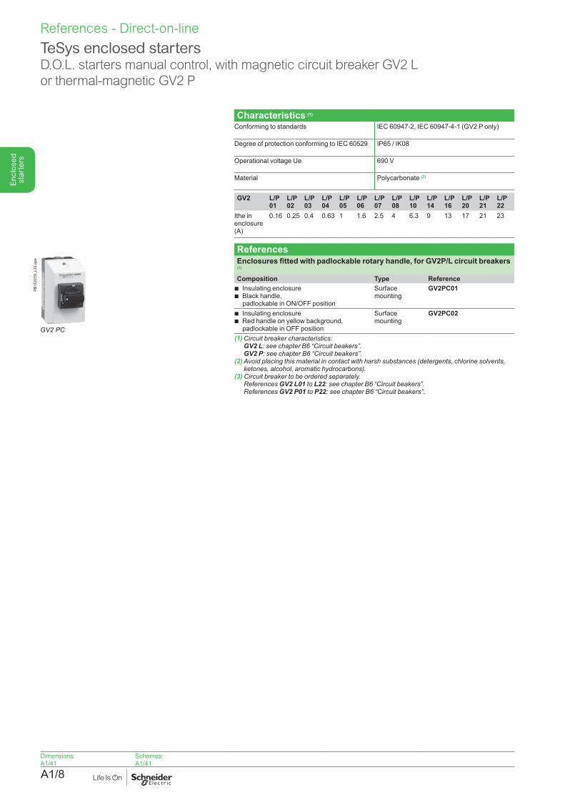
Characteristics (1)
Conforming to standards IEC 60947-2, IEC 60947-4-1 (GV2 P only)
Degree of protection conforming to IEC 60529 IP65 / IK08
Operational voltage Ue 690 V
Material Polycarbonate (2)
GV2 L/P 01
L/P 02
L/P 03
L/P 04
L/P 05
L/P 06
L/P 07
L/P 08
L/P 10
L/P 14
L/P 16
L/P 20
L/P 21
L/P 22
Ithe in enclosure (A)
0.16 0.25 0.4 0.63 1 1.6 2.5 4 6.3 9 13 17 21 23
ReferencesEnclosures fitted with padlockable rotary handle, for GV2P/L circuit breakers (3)
Composition Type Reference b Insulating enclosure b Black handle,padlockable in ON/OFF position
Surface mounting
GV2PC01
b Insulating enclosure b Red handle on yellow background, padlockable in OFF position
Surface mounting
GV2PC02
(1) Circuit breaker characteristics: GV2 L: seechapterB6“Circuitbeakers”. GV2 P: seechapterB6“Circuitbeakers”.
(2) Avoid placing this material in contact with harsh substances (detergents, chlorine solvents, ketones,alcohol,aromatichydrocarbons).
(3)Circuitbreakertobeorderedseparately. References GV2 L01 to L22: seechapterB6“Circuitbeakers”. References GV2 P01 to P22: seechapterB6“Circuitbeakers”.
TeSys enclosed startersD.O.L. starters manual control, with magnetic circuit breaker GV2 L or thermal-magnetic GV2 P
Dimensions:A1/41
Schemes: A1/41
GV2 PC
PB11
2219
_L32
.eps
A1/9
Enc
lose
d st
arte
rs
References - Direct-on-line
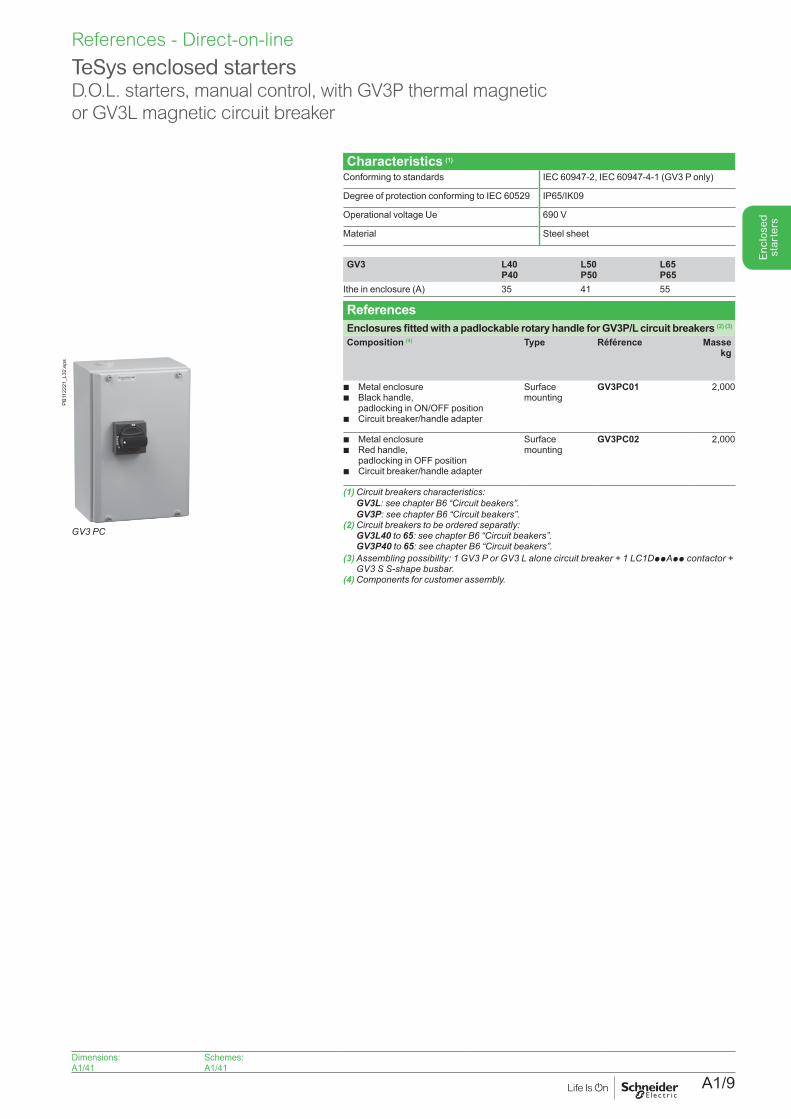
Characteristics (1)
Conforming to standards IEC 60947-2, IEC 60947-4-1 (GV3 P only)
Degree of protection conforming to IEC 60529 IP65/IK09
Operational voltage Ue 690 V
Material Steel sheet
GV3 L40 P40
L50 P50
L65 P65
Ithe in enclosure (A) 35 41 55
ReferencesEnclosures fitted with a padlockable rotary handle for GV3P/L circuit breakers (2) (3)
Composition (4) Type Référence Masse kg
b Metal enclosureb Black handle,
padlocking in ON/OFF positionb Circuit breaker/handle adapter
Surface mounting
GV3PC01 2,000
b Metal enclosureb Red handle,
padlocking in OFF positionb Circuit breaker/handle adapter
Surface mounting
GV3PC02 2,000
(1) Circuit breakers characteristics: GV3L:seechapterB6“Circuitbeakers”. GV3P:seechapterB6“Circuitbeakers”.(2) Circuit breakers to be ordered separatly: GV3L40 to 65: seechapterB6“Circuitbeakers”. GV3P40 to 65: seechapterB6“Circuitbeakers”.(3) Assembling possibility: 1 GV3 P or GV3 L alone circuit breaker + 1 LC1DppApp contactor +
GV3SS-shapebusbar.(4)Componentsforcustomerassembly.
TeSys enclosed startersD.O.L. starters, manual control, with GV3P thermal magnetic or GV3L magnetic circuit breaker
PB11
2221
_L32
.eps
GV3 PC
Dimensions:A1/41
Schemes: A1/41
A1/10
Enc
lose
d st
arte
rsReferences - Direct-on-line
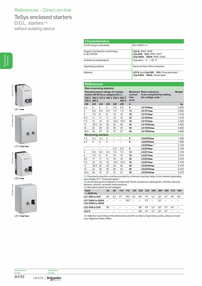
TeSys enclosed startersD.O.L. starters (1)
without isolating device
CharacteristicsConforming to standards IEC 60947-4-1
Degree of protection conforming to IEC 60529
LE2 K: IP65 / IK09LEp D09…D35: IP65 / IK07LEp D40A…D65A: IP65 / IK09
Ambient air temperature Operation: - 5…+ 40 °C
Operating positions Same as that of the contactors
Material LE2 K and LEp D09…D35: Polycarbonate (2) LEp D40A…D65A: Sheet steel
ReferencesNon-reversing startersStandard power ratings of 3-phase motors 50-60 Hz in category AC-3
Maximum current I the up to
Basic reference, to be completed by adding the voltage code (3)
Weight
220 V230 V
380 V400 V
415 V 440 V 500 V 660 V690 V
kW kW kW kW kW kW A kg2.2 4 4 4 5.5 5.5 9 LE1D09pp 0.9203 5.5 5.5 5.5 7.5 7.5 12 LE1D12pp 0.9204 7.5 9 9 10 10 18 LE1D18pp 1.0155.5 11 11 11 15 15 25 LE1D25pp 1.0157.5 15 15 15 18.5 18.5 35 LE1D35pp 4.32011 18.5 22 22 22 30 40 LE1D40App 4.82015 22 25 30 30 33 50 LE1D50App 4.85018.5 30 37 37 37 37 65 LE1D65App 4.850Reversing starters
1.5 2.2 2.2 3 – – 6 LE2K065pp 1.0802.2 4 4 4 – – 9 LE2K095pp 1.080
LE2D09pp (4) 2.100– – – – 5.5 5.5 9 LE2D09pp 2.1003 5.5 5.5 5.5 7.5 7.5 12 LE2D12pp 2.1004 7.5 9 9 10 10 18 LE2D18pp 2.4105.5 11 11 11 15 15 25 LE2D25pp 2.5707.5 15 15 15 18.5 18.5 35 LE2D35pp 4.10011 18.5 22 22 22 30 40 LE2D40App 5.27015 22 25 30 30 33 50 LE2D50App 5.47018.5 30 37 37 37 37 65 LE2D65App 5.470(1) Overload protection must be provided by a thermal overload relay, to be ordered separately, seechapterB11“Overloadrelays”.(2) Avoid placing this material in contact with harsh substances (detergents, chlorine solvents, ketones,alcohol,aromatichydrocarbons).(3) Standard control circuit voltages: Volts a 50/60 Hz
24 48 110 115 120 220 230 240 380 400 415 440
LE1 D09 to D35 B7 E7 F7 FE7 G7 M7 P7 U7 Q7 V7 N7 R7LE1 D40A to D65A,LE2 D40A to D65A
– – – FE7 – – P7 – Q7 – – –
LE2 D09 to D35 B7 – – – – M7 P7 U7 Q7 V7 N7 –LE2 K – – – – – M7 P7 U7 Q7 V7 – –
(4) Selection according to the dimensions and the number of operating cycles, please consult yourRegionalSalesOffice.
Dimensions:A1/42
Schemes:A1/43
LE1 Dpp
PB11
2259
_L32
.eps
LE2 Dpp
PB11
2274
_L32
.eps
LE1 DppApp
PB11
2263
_L32
.eps
LE2 DppApp
PB11
2284
_L32
.eps
A1/11
Enc
lose
d st
arte
rs
References - Direct-on-line
TeSys enclosed startersD.O.L. starters (1) without isolating device
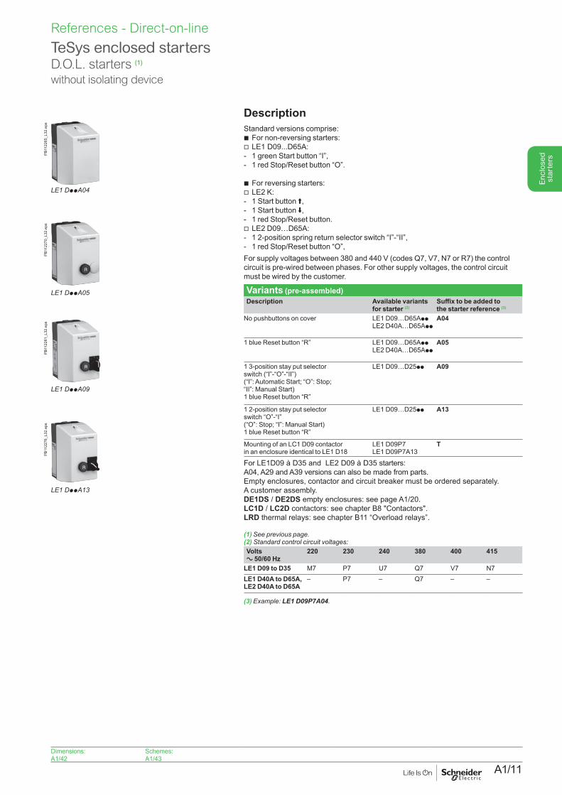
DescriptionStandard versions comprise: b For non-reversing starters:
v LE1 D09...D65A:- 1 green Start button “I”,- 1 red Stop/Reset button “O”.
b For reversing starters:v LE2 K:- 1 Start button A,- 1 Start button E,- 1 red Stop/Reset button.v LE2 D09…D65A:- 1 2-position spring return selector switch “I”-“II”,- 1 red Stop/Reset button “O”,For supply voltages between 380 and 440 V (codes Q7, V7, N7 or R7) the control circuit is pre-wired between phases. For other supply voltages, the control circuit must be wired by the customer.
Variants (pre-assembled)Description Available variants
for starter (2)Suffix to be added to the starter reference (3)
No pushbuttons on cover
LE1 D09…D65App LE2 D40A…D65App
A04
1 blue Reset button “R”
LE1 D09…D65App LE2 D40A…D65App
A05
1 3-position stay put selector switch (“I”-“O”-“II”) (“I”: Automatic Start; “O”: Stop; “II”: Manual Start) 1 blue Reset button “R”
LE1 D09…D25pp A09
1 2-position stay put selector switch “O”-“I” (“O”: Stop; “I”: Manual Start) 1 blue Reset button “R”
LE1 D09…D25pp A13
Mounting of an LC1 D09 contactor in an enclosure identical to LE1 D18
LE1 D09P7 LE1 D09P7A13
T
For LE1D09 à D35 and LE2 D09 à D35 starters:A04, A29 and A39 versions can also be made from parts.Empty enclosures, contactor and circuit breaker must be ordered separately.A customer assembly.DE1DS / DE2DS empty enclosures: see page A1/20.LC1D / LC2D contactors: see chapter B8 "Contactors".LRD thermal relays: see chapter B11 “Overload relays”.
(1)Seepreviouspage.(2) Standard control circuit voltages: Volts a 50/60 Hz
220 230 240 380 400 415
LE1 D09 to D35 M7 P7 U7 Q7 V7 N7LE1 D40A to D65A,LE2 D40A to D65A
– P7 – Q7 – –
(3) Example: LE1 D09P7A04.
Dimensions:A1/42
Schemes:A1/43
LE1 DppA04
PB11
2265
_L32
.eps
LE1 DppA05
PB11
2270
_L32
.eps
LE1 DppA09
PB11
2281
_L32
.eps
LE1 DppA13
PB11
2276
_L32
.eps
A1/12
Enc
lose
d st
arte
rsReferences - Direct-on-line
TeSys enclosed startersD.O.L. starterswith 3-phase thermal overload relay with 3 protected phases
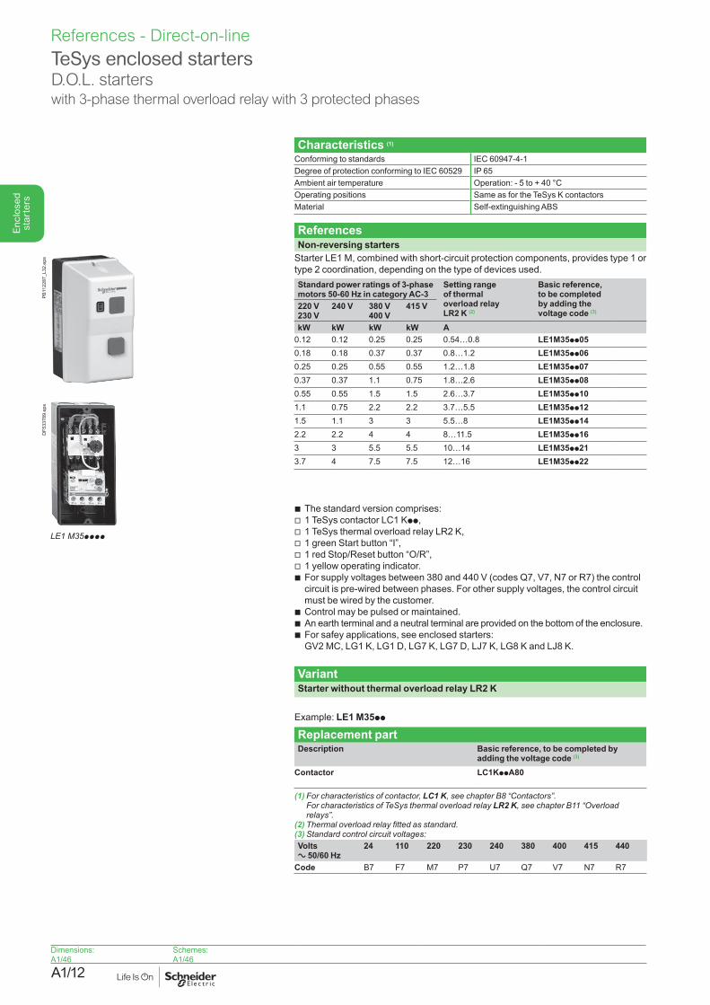
Characteristics (1)
Conforming to standards IEC 60947-4-1Degree of protection conforming to IEC 60529 IP 65Ambient air temperature Operation: - 5 to + 40 °COperating positions Same as for the TeSys K contactorsMaterial Self-extinguishing ABS
ReferencesNon-reversing starters
Starter LE1 M, combined with short-circuit protection components, provides type 1 or type 2 coordination, depending on the type of devices used.Standard power ratings of 3-phase motors 50-60 Hz in category AC-3
Setting range of thermal overload relay LR2 K (2)
Basic reference, to be completed by adding the voltage code (3)
220 V230 V
240 V 380 V 400 V
415 V
kW kW kW kW A0.12 0.12 0.25 0.25 0.54…0.8 LE1M35pp050.18 0.18 0.37 0.37 0.8…1.2 LE1M35pp060.25 0.25 0.55 0.55 1.2…1.8 LE1M35pp070.37 0.37 1.1 0.75 1.8…2.6 LE1M35pp080.55 0.55 1.5 1.5 2.6…3.7 LE1M35pp101.1 0.75 2.2 2.2 3.7…5.5 LE1M35pp121.5 1.1 3 3 5.5…8 LE1M35pp142.2 2.2 4 4 8…11.5 LE1M35pp163 3 5.5 5.5 10…14 LE1M35pp213.7 4 7.5 7.5 12…16 LE1M35pp22
Descriptionb The standard version comprises:v 1 TeSys contactor LC1 Kpp,v 1 TeSys thermal overload relay LR2 K,v 1 green Start button “I”,v 1 red Stop/Reset button “O/R”,v 1 yellow operating indicator.b For supply voltages between 380 and 440 V (codes Q7, V7, N7 or R7) the control
circuit is pre-wired between phases. For other supply voltages, the control circuit must be wired by the customer.
b Control may be pulsed or maintained.b An earth terminal and a neutral terminal are provided on the bottom of the enclosure.b For safey applications, see enclosed starters:
GV2 MC, LG1 K, LG1 D, LG7 K, LG7 D, LJ7 K, LG8 K and LJ8 K.
VariantStarter without thermal overload relay LR2 K
Delete the last 2 digits of the starter references selected above.Example: LE1 M35pp
Replacement partDescription Basic reference, to be completed by
adding the voltage code (3)
Contactor LC1KppA80
(1) For characteristics of contactor, LC1 K,seechapterB8“Contactors”. For characteristics of TeSys thermal overload relay LR2 K, see chapter B11 “Overload relays”.
(2)Thermaloverloadrelayfittedasstandard.(3) Standard control circuit voltages: Volts a 50/60 Hz
24 110 220 230 240 380 400 415 440
Code B7 F7 M7 P7 U7 Q7 V7 N7 R7
Dimensions:A1/46
Schemes:A1/46
LE1M35pppp
DF5
3378
9.ep
sPB
1122
87_L
32.e
ps
A1/13
Enc
lose
d st
arte
rs
References - Direct-on-line
TeSys enclosed startersD.O.L. starters with thermal magnetic circuit breaker and contactor
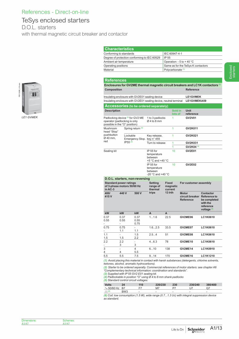
CharacteristicsConforming to standards IEC 60947-4-1Degree of protection conforming to IEC 60529 IP 55Ambient air temperature Operation: - 5 to + 40 °COperating positions Same as for the TeSys K contactorsMaterial Polycarbonate (1)
ReferencesEnclosures for GV2ME thermal magnetic circuit breakers and LC1K contactors (2)
Composition Reference
Insulating enclosure with GV2E01 sealing device LE1GVMEKInsulating enclosure with GV2E01 sealing device, neutral terminal LE1GVMEKA59
Accessories (to be ordered separately)Description Sold in
lots ofUnit reference
Padlocking device (3) for GV2 ME operator (padlocking is only possible in the “O” position)
1 to 3 padlocks Ø 4 to 8 mm
1 GV2V01
Mushroom head “Stop” pushbutton Ø 40 mm, red
Spring return (3) 1 GV2K011
Lockable Emergency Stop. IP55 (3)
Key release, key n° 455
1 GV2K021
Turn to release 1 GV2K0311 GV2K04 (4)
Sealing kit IP 55 for temperature between +5 °C and +40 °C
10 GV2E01
IP 55 for temperature between -20 °C and +40 °C
10 GV2E02
D.O.L. starters, non-reversingStandard power ratings of 3-phase motors 50/60 Hz in AC-3
Setting range of thermal trips
Fixed magnetic current 13 Irth
For customer assembly
400/ 415 V
440 V 500 V Motor circuit breaker Reference
Contactor Reference to be completed with the reference voltage (5)
kW kW kW A A0.37 0.55 -
0.37 0.55 -
0.37 0.55 0.75
1...1.6 22.5 GV2ME06 LC1K0610
0.75 -
0.75 1.1
- 1.1
1.6...2.5 33.5 GV2ME07 LC1K0610
1.1 1.5
- 1.5
1.5 2.2
2.5...4 51 GV2ME08 LC1K0610
2.2 -
2.2 3
- 3
4...6.3 78 GV2ME10 LC1K0610
3 4
- 4
4 5.5
6...10 138 GV2ME14 LC1K0910
5.5 5.5 7.5 9...14 170 GV2ME16 LC1K1210(1) Avoid placing this material in contact with harsh substances (detergents, chlorine solvents, ketones,alcohol,aromatichydrocarbons).(2) Startertobeorderedseparatly.Commercialreferencesofmotorstarters:seechapterA6 “Complementarytechnicalinformation:coordinationandstandards”.(3)SuppliedwithIP55GV2E01sealingkit.(4) Padlockable in position “O” using Ø 4 to 8 mm shank padlocks (5) Standard control circuit voltages: Volts 24 110 220/230 230 230/240 380/400a 50/60 Hz B7 F7 M7 P7 U7 Q7c (6) BW3 - - - - -
(6)Coil:lowconsumption(1.5W),widerange(0.7...1.3Uc)withintegralsuppressiondevice asstandard.
PB11
2286
_L32
.eps
LE1 GVMEK
Dimensions:A1/47
Schemes:A1/47
A1/14
Enc
lose
d st
arte
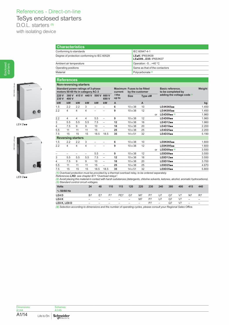
rsReferences - Direct-on-lineTeSys enclosed startersD.O.L. starters (1)
with isolating device
CharacteristicsConforming to standards IEC 60947-4-1Degree of protection conforming to IEC 60529 LEpK: IP65/IK09
LEpD09...D35: IP65/IK07 Ambient air temperature Operation: -5…+40 °COperating positions Same as that of the contactorsMaterial Polycarbonate (2)
ReferencesNon-reversing startersStandard power ratings of 3-phase motors 50-60 Hz in category AC-3
Maximum current I the up to
Fuses to be fitted by the customer
Basic reference, to be completed by adding the voltage code (3)
Weight
220 V230 V
380 V400 V
415 V 440 V 500 V 660 V690 V
Size Type aM
kW kW kW kW kW kW A A kg1.5 2.2 2.2 3 – – 6 10 x 38 10 LE4K065pp 1.4502.2 4 4 4 – – 9 10 x 38 12 LE4K095pp 1.450
or LE4D09pp (4) 1.9602.2 4 4 4 5.5 – 9 10 x 38 12 LE4D09pp 1.9603 5.5 5.5 5.5 7.5 – 12 10 x 38 16 LE4D12pp 1.9604 7.5 9 9 10 – 18 10 x 38 20 LE4D18pp 2.2005.5 11 11 11 15 – 25 10 x 38 25 LE4D25pp 2.2007.5 15 15 15 18.5 18.5 35 14 x 51 32 LE4D35pp 5.190Reversing starters
1.5 2.2 2.2 3 – – 6 10 x 38 10 LE8K065pp 1.6002.2 4 4 4 – – 9 10 x 38 12 LE8K095pp 1.600
or LE8D09pp (4) 3.550– – – – 5.5 – 9 10 x 38 12 LE8D09pp 3.5503 5.5 5.5 5.5 7.5 – 12 10 x 38 16 LE8D12pp 3.5504 7.5 9 9 10 – 18 10 x 38 20 LE8D18pp 3.7005.5 11 11 11 15 – 25 10 x 38 25 LE8D25pp 4.6707.5 15 15 15 18.5 18.5 35 14 x 51 32 LE8D35pp 5.800 (1)Overloadprotectionmustbeprovidedbyathermaloverloadrelay,tobeorderedseparately. References LRD:seechapterB11“Overloadrelays”.(2)Avoidplacingthismaterialincontactwithharshsubstances(detergents,chlorinesolvents,ketones,alcohol,aromatichydrocarbons).(3)Standardcontrolcircuitvoltages.Volts 24 48 110 115 120 220 230 240 380 400 415 440a 50/60 Hz
LE4 D B7 E7 F7 FE7 G7 M7 P7 U7 Q7 V7 N7 R7LE4 K – – – – – M7 P7 U7 Q7 V7 – –LE8 K, LE8 D – – – – – – P7 – Q7 V7 – –(4)Selectionaccordingtodimensionsandthenumberofoperatingcycles,pleaseconsultyourRegionalSalesOffice.
Dimensions:A1/44
Schemes:A1/45
LE4 Dpp
PB11
2292
_L32
.eps
LE8 Dpp
PB11
2301
_L32
.eps
A1/15
Enc
lose
d st
arte
rs
References - Direct-on-line
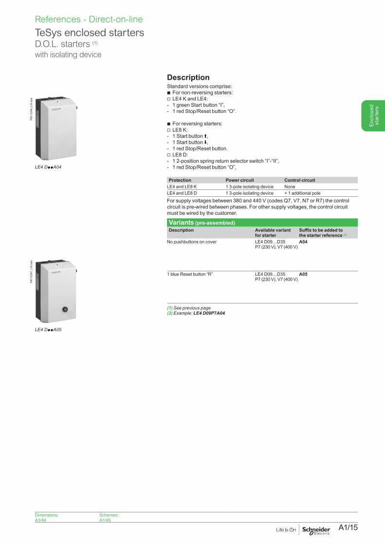
TeSys enclosed startersD.O.L. starters (1)
with isolating device
DescriptionStandard versions comprise: b For non-reversing starters:v LE4 K and LE4:- 1 green Start button “I”,- 1 red Stop/Reset button “O”.
b For reversing starters:v LE8 K:- 1 Start button A,- 1 Start button E,- 1 red Stop/Reset button.v LE8 D:- 1 2-position spring return selector switch “I”-“II”,- 1 red Stop/Reset button “O”,
Protection Power circuit Control circuitLE4 and LE8 K 1 3-pole isolating device NoneLE4 and LE8 D 1 3-pole isolating device + 1 additional poleFor supply voltages between 380 and 440 V (codes Q7, V7, N7 or R7) the control circuit is pre-wired between phases. For other supply voltages, the control circuit must be wired by the customer.
Variants (pre-assembled)Description Available variant
for starterSuffix to be added to the starter reference (2)
No pushbuttons on cover LE4 D09…D35 P7 (230 V), V7 (400 V)
A04
1 blue Reset button “R” LE4 D09…D35 P7 (230 V), V7 (400 V)
A05
(1) See previous page(2) Example: LE4 D09P7A04.
Dimensions:A1/44
Schemes:A1/45
LE4 DppA04
PB11
2294
_L32
.eps
LE4 DppA05
PB11
2297
_L32
.eps
A1/16
Enc
lose
d st
arte
rs
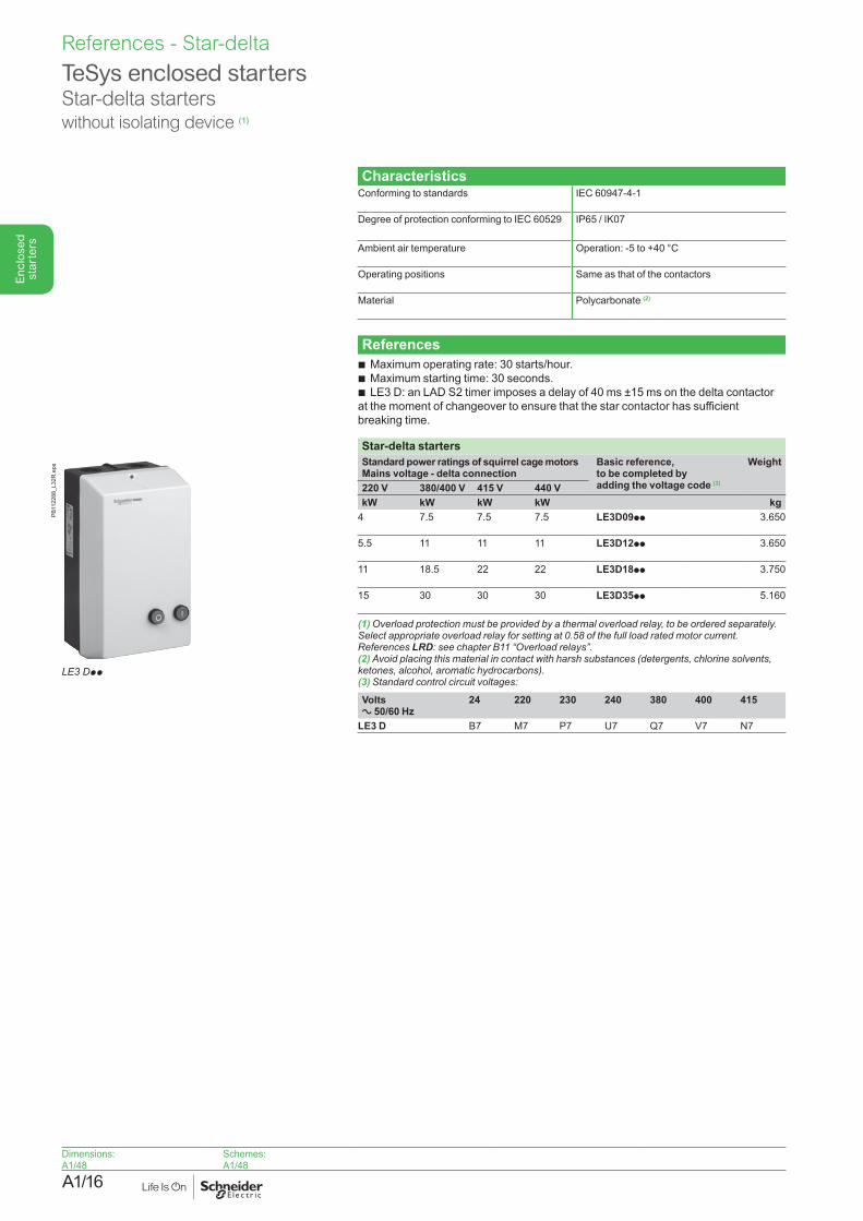
TeSys enclosed startersStar-delta starterswithout isolating device (1)
CharacteristicsConforming to standards IEC 60947-4-1
Degree of protection conforming to IEC 60529 IP65 / IK07
Ambient air temperature Operation: -5 to +40 °C
Operating positions Same as that of the contactors
Material Polycarbonate (2)
Referencesb Maximum operating rate: 30 starts/hour.b Maximum starting time: 30 seconds.b LE3 D: an LAD S2 timer imposes a delay of 40 ms ±15 ms on the delta contactor at the moment of changeover to ensure that the star contactor has sufficient breaking time.
Star-delta startersStandard power ratings of squirrel cage motors Mains voltage - delta connection
Basic reference, to be completed by adding the voltage code (3)
Weight
220 V 380/400 V 415 V 440 VkW kW kW kW kg
4 7.5 7.5 7.5 LE3D09pp 3.650
5.5 11 11 11 LE3D12pp 3.650
11 18.5 22 22 LE3D18pp 3.750
15 30 30 30 LE3D35pp 5.160
(1)Overloadprotectionmustbeprovidedbyathermaloverloadrelay,tobeorderedseparately.Selectappropriateoverloadrelayforsettingat0.58ofthefullloadratedmotorcurrent. References LRD:seechapterB11“Overloadrelays”.(2) Avoid placing this material in contact with harsh substances (detergents, chlorine solvents, ketones,alcohol,aromatichydrocarbons).(3) Standard control circuit voltages:
Volts a 50/60 Hz
24 220 230 240 380 400 415
LE3 D B7 M7 P7 U7 Q7 V7 N7
Dimensions:A1/48
Schemes:A1/48
LE3 Dpp
PB11
2288
_L32
R.e
psReferences - Star-delta
A1/17
Enc
lose
d st
arte
rs
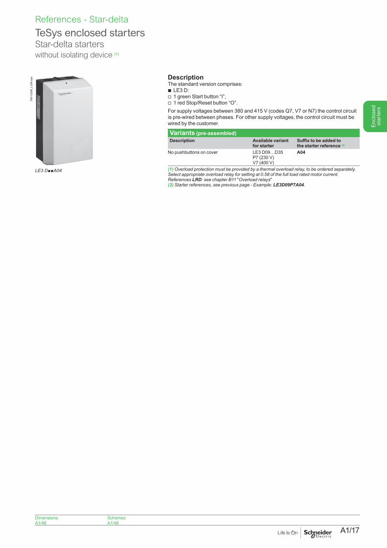
TeSys enclosed startersStar-delta starterswithout isolating device (1)
DescriptionThe standard version comprises:b LE3 D:v 1 green Start button “I”,v 1 red Stop/Reset button “O”.For supply voltages between 380 and 415 V (codes Q7, V7 or N7) the control circuit is pre-wired between phases. For other supply voltages, the control circuit must be wired by the customer.
Variants (pre-assembled)Description Available variant
for starterSuffix to be added to the starter reference (2)
No pushbuttons on cover LE3 D09…D35 P7 (230 V) V7 (400 V)
A04
(1)Overloadprotectionmustbeprovidedbyathermaloverloadrelay,tobeorderedseparately.Selectappropriateoverloadrelayforsettingat0.58ofthefullloadratedmotorcurrent.References LRD: see chapter B11 "Overload relays"(2) Starter references, see previous page - Example: LE3D09P7A04.
LE3 DppA04
PB11
2289
_L32
R.e
ps
Dimensions:A1/48
Schemes:A1/48
References - Star-delta
A1/18
Enc
lose
d st
arte
rs
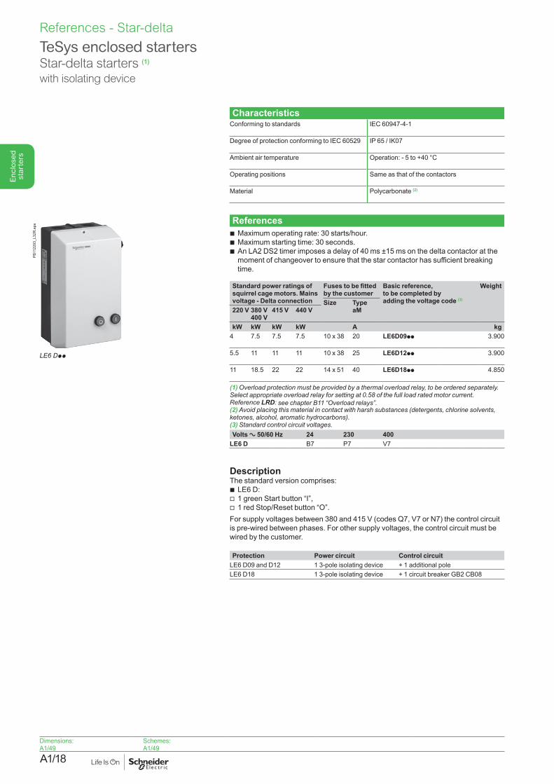
TeSys enclosed startersStar-delta starters (1)
with isolating device
CharacteristicsConforming to standards IEC 60947-4-1
Degree of protection conforming to IEC 60529 IP 65 / IK07
Ambient air temperature Operation: - 5 to +40 °C
Operating positions Same as that of the contactors
Material Polycarbonate (2)
Referencesb Maximum operating rate: 30 starts/hour.b Maximum starting time: 30 seconds.b An LA2 DS2 timer imposes a delay of 40 ms ±15 ms on the delta contactor at the
moment of changeover to ensure that the star contactor has sufficient breaking time.
Standard power ratings of squirrel cage motors. Mains voltage - Delta connection
Fuses to be fitted by the customer
Basic reference, to be completed by adding the voltage code (3)
Weight
Size Type aM220 V 380 V
400 V415 V 440 V
kW kW kW kW A kg4 7.5 7.5 7.5 10 x 38 20 LE6D09pp 3.900
5.5 11 11 11 10 x 38 25 LE6D12pp 3.900
11 18.5 22 22 14 x 51 40 LE6D18pp 4.850
(1)Overloadprotectionmustbeprovidedbyathermaloverloadrelay,tobeorderedseparately.Selectappropriateoverloadrelayforsettingat0.58ofthefullloadratedmotorcurrent.Reference LRD: seechapterB11“Overloadrelays”.(2) Avoid placing this material in contact with harsh substances (detergents, chlorine solvents, ketones,alcohol,aromatichydrocarbons).(3)Standardcontrolcircuitvoltages.Volts a 50/60 Hz 24 230 400
LE6 D B7 P7 V7
DescriptionThe standard version comprises:b LE6 D:v 1 green Start button “I”,v 1 red Stop/Reset button “O”.For supply voltages between 380 and 415 V (codes Q7, V7 or N7) the control circuit is pre-wired between phases. For other supply voltages, the control circuit must be wired by the customer. Protection Power circuit Control circuit
LE6 D09 and D12 1 3-pole isolating device + 1 additional poleLE6 D18 1 3-pole isolating device + 1 circuit breaker GB2 CB08
Dimensions:A1/49
Schemes:A1/49
LE6 Dpp
PB11
2293
_L32
R.e
psReferences - Star-delta
A1/19
Enc
lose
d st
arte
rs
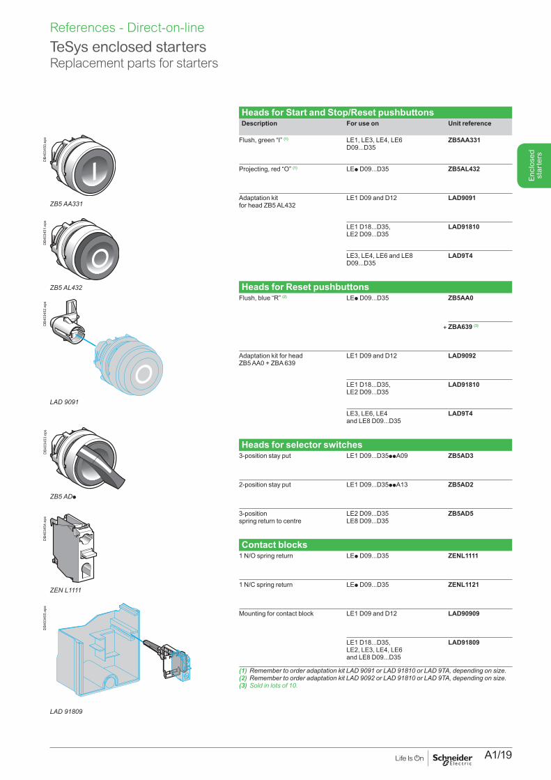
Heads for Start and Stop/Reset pushbuttonsDescription For use on Unit reference
Flush, green “I” (1) LE1, LE3, LE4, LE6 D09...D35
ZB5AA331
Projecting, red “O” (1) LEp D09...D35 ZB5AL432
Adaptation kit for head ZB5 AL432
LE1 D09 and D12 LAD9091
LE1 D18...D35,LE2 D09...D35
LAD91810
LE3, LE4, LE6 and LE8 D09...D35
LAD9T4
Heads for Reset pushbuttonsFlush, blue “R” (2) LEp D09...D35
+
ZB5AA0
ZBA639 (3)
Adaptation kit for head ZB5 AA0 + ZBA 639
LE1 D09 and D12 LAD9092
LE1 D18...D35, LE2 D09...D35
LAD91810
LE3, LE6, LE4 and LE8 D09...D35
LAD9T4
Heads for selector switches3-position stay put LE1 D09...D35ppA09 ZB5AD3
2-position stay put LE1 D09...D35ppA13 ZB5AD2
3-position spring return to centre
LE2 D09...D35 LE8 D09...D35
ZB5AD5
Contact blocks1 N/O spring return LEp D09...D35 ZENL1111
1 N/C spring return LEp D09...D35 ZENL1121
Mounting for contact block LE1 D09 and D12 LAD90909
LE1 D18...D35,LE2, LE3, LE4, LE6 and LE8 D09...D35
LAD91809
(1)RemembertoorderadaptationkitLAD9091orLAD91810orLAD9TA,dependingonsize.(2)RemembertoorderadaptationkitLAD9092orLAD91810orLAD9TA,dependingonsize.(3)Soldinlotsof10.
TeSys enclosed starters Replacement parts for starters
ZB5AA331
DB4
0345
0.ep
s
ZB5AL432
DB4
0345
1.ep
s
LAD 9091
DB4
0345
2.ep
s
ZB5ADp
DB4
0345
3.ep
s
ZENL1111
DB4
0345
4.ep
s
LAD 91809
DB4
0345
5.ep
s
References - Direct-on-line
A1/20
Enc
lose
d st
arte
rs
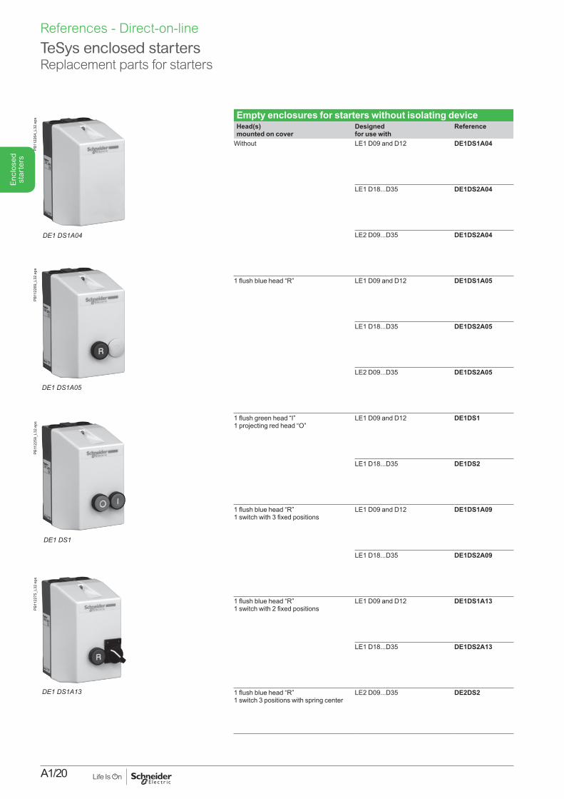
Empty enclosures for starters without isolating deviceHead(s) mounted on cover
Designed for use with
Reference
Without LE1 D09 and D12 DE1DS1A04
LE1 D18...D35 DE1DS2A04
LE2 D09...D35 DE1DS2A04
1 flush blue head “R” LE1 D09 and D12 DE1DS1A05
LE1 D18...D35 DE1DS2A05
LE2 D09...D35 DE1DS2A05
1 flush green head “I” 1 projecting red head “O”
LE1 D09 and D12 DE1DS1
LE1 D18...D35 DE1DS2
1 flush blue head “R” 1 switch with 3 fixed positions
LE1 D09 and D12 DE1DS1A09
LE1 D18...D35 DE1DS2A09
1 flush blue head “R” 1 switch with 2 fixed positions
LE1 D09 and D12 DE1DS1A13
LE1 D18...D35 DE1DS2A13
1 flush blue head “R” 1 switch 3 positions with spring center
LE2 D09...D35 DE2DS2
TeSys enclosed starters Replacement parts for starters
DE1 DS1A04
PB11
2264
_L32
.eps
DE1DS1A05
PB11
2269
_L32
.eps
DE1 DS1
PB11
2259
_L32
.eps
DE1 DS1A13
PB11
2275
_L32
.eps
References - Direct-on-line
A1/21
Enc
lose
d st
arte
rs
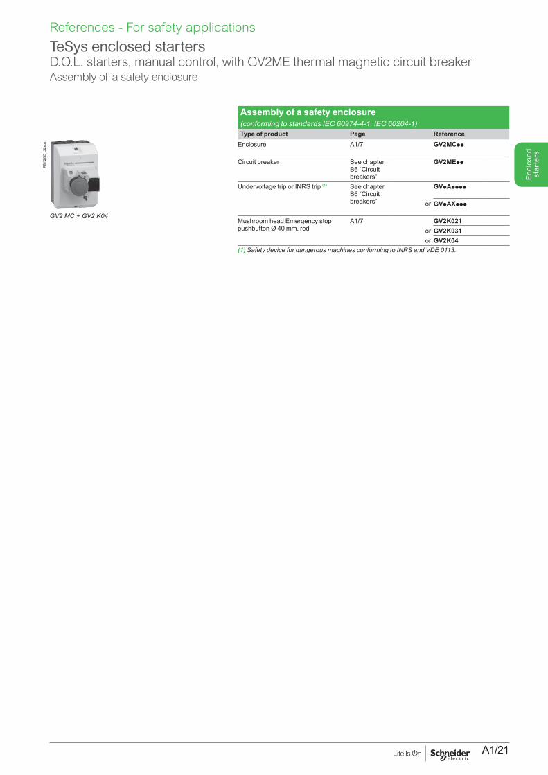
Assembly of a safety enclosure (conforming to standards IEC 60974-4-1, IEC 60204-1)Type of product Page Reference
Enclosure A1/7 GV2MCpp
Circuit breaker See chapter B6 “Circuit breakers”
GV2MEpp
Undervoltage trip or INRS trip (1) See chapter B6 “Circuit breakers”
GVpApppp
or GVpAXppp
Mushroom head Emergency stop pushbutton Ø 40 mm, red
A1/7 GV2K021or GV2K031or GV2K04
(1)SafetydevicefordangerousmachinesconformingtoINRSandVDE0113.
TeSys enclosed startersD.O.L. starters, manual control, with GV2ME thermal magnetic circuit breakerAssembly of a safety enclosure
PB11
2215
_L32
.eps
GV2 MC + GV2 K04
References - For safety applications
A1/22
Enc
lose
d st
arte
rs
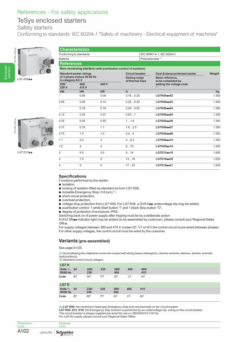
TeSys enclosed startersSafety startersConforming to standards: IEC 60204-1 "Safety of machinery - Electrical equipment of machines"
CharacteristicsConforming to standards IEC 60947-4-1, IEC 60204-1Material Polycarbonate (1)
ReferencesNon-reversing starters (with pushbutton control of isolation)Standard power ratings of 3-phase motors 50-60 Hz in category AC-3
Circuit breaker Dust & damp protected starter WeightSetting range of thermal trips
Basic reference, to be completed by adding the voltage code (2)
220/ 230 V
400/ 415 V
440 V
kW kW kW A kg– 0.06 0.06 0.16…0.25 LG7K06pp02 1.300
0.06 0.09 0.12 0.25…0.40 LG7K06pp03 1.300
– 0.18 0.18 0.40…0.63 LG7K06pp04 1.300
0.12 0.25 0.37 0.63…1 LG7K06pp05 1.300
0.25 0.55 0.55 1…1.6 LG7K06pp06 1.300
0.37 0.75 1.1 1.6…2.5 LG7K06pp07 1.300
0.75 1.5 1.5 2.5…4 LG7K06pp08 1.300
1.1 2.2 3 4…6.3 LG7K06pp10 1.300
1.5 4 4 6…10 LG7K09pp14 1.450
3 5.5 5.5 9…14 LG7D12pp16 1.600
4 7.5 9 13…18 LG7D18pp20 1.630
4 9 9 17…23 LG7D18pp21 1.630
SpecificationsFunctions performed by the starter:b isolation,b locking of isolation fitted as standard as from LG7 K09,b lockable Emergency Stop (1/4 turn) (3),b short-circuit protection,b overload protection,b voltage drop protection from LG7 K09. For LG7 K06, a GVA Xpp undervoltage trip may be added,b pushbutton control: 1 white Start button “I” and 1 black Stop button “O”,b degree of protection of enclosure: IP55.Switching back on of power supply after tripping must be by a deliberate action.A GV2 SNpp indicator light may be added (to be assembled by customer), please consult your Regional Sales Office.For supply voltages between 380 and 415 V (codes Q7, V7 or N7) the control circuit is pre-wired between phases. For other supply voltages, the control circuit must be wired by the customer.
Variants (pre-assembled) See page A1/25.(1) Avoid allowing the material to come into contact with strong bases (detergents, chlorine solvents, ketones, alcohol, aromatic hydrocarbons).(2) Standard control circuit voltages:
LG7 KVolts a 50/60 Hz
24 220/ 230
230 380/ 400
400 400/ 415
Code B7 M7 P7 Q7 V7 N7
LG7 DVolts a 50/60 Hz
24 220/ 230
230 380/ 400
400 415
Code B7 M7 P7 Q7 V7 N7
(3) LG7 K06:themushroomheadtypeEmergencyStopactsmechanicallyonthecircuitbreaker. LG7 K09, D12, D18:theEmergencyStopfunctionisperformedbyanundervoltagetrip,actingonthecircuitbreaker. Thiscircuitbreakerisalwayssuppliedpre-wiredforuseon380/400/415V50Hz. Fora60Hzsupply,pleaseconsultyourRegionalSalesOffice.
LG7 K06pp
PB11
1880
_L32
R.e
ps
LG7 D12pp
PB11
1886
_L32
R.e
ps
Dimensions:A1/50
Schemes:A1/51
References - For safety applications
A1/23
Enc
lose
d st
arte
rs
TeSys enclosed startersSafety startersConforming to standards: IEC 60204-1 "Safety of machinery - Electrical equipment of machines"
CharacteristicsConforming to standards IEC 60947-4-1, IEC 60204-1Material Polycarbonate (1)
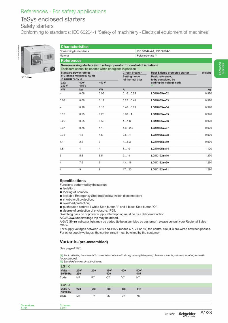
ReferencesNon-reversing starters (with rotary operator for control of isolation)Enclosure cannot be opened when energised in position “I”.Standard power ratings of 3-phase motors 50-60 Hz in category AC-3
Circuit breaker Dust & damp protected starter WeightSetting range of thermal trips
Basic reference, to be completed by adding the voltage code (2)
220/ 230 V
400/ 415 V
440 V
kW kW kW A kg– 0.06 0.06 0.16…0.25 LG1K065pp02 0.970
0.06 0.09 0.12 0.25…0.40 LG1K065pp03 0.970
– 0.18 0.18 0.40…0.63 LG1K065pp04 0.970
0.12 0.25 0.25 0.63…1 LG1K065pp05 0.970
0.25 0.55 0.55 1…1.6 LG1K065pp06 0.970
0.37 0.75 1.1 1.6…2.5 LG1K065pp07 0.970
0.75 1.5 1.5 2.5…4 LG1K065pp08 0.970
1.1 2.2 3 4…6.3 LG1K065pp10 0.970
1.5 4 4 6…10 LG1K095pp14 1.120
3 5.5 5.5 9…14 LG1D122pp16 1.270
4 7.5 9 13…18 LG1D182pp20 1.290
4 9 9 17…23 LG1D182pp21 1.290
SpecificationsFunctions performed by the starter:b isolation,b locking of isolation,b lockable Emergency Stop (red/yellow switch-disconnector),b short-circuit protection,b overload protection,b pushbutton control: 1 white Start button "I" and 1 black Stop button "O",b degree of protection of enclosure: IP55.Switching back on of power supply after tripping must be by a deliberate action.A GVA Xpp undervoltage trip may be added. A GV2 SNpp indicator light may be added (to be assembled by customer), please consult your Regional Sales Office.For supply voltages between 380 and 415 V (codes Q7, V7 or N7) the control circuit is pre-wired between phases. For other supply voltages, the control circuit must be wired by the customer.
Variants (pre-assembled) See page A1/25.
(1) Avoid allowing the material to come into contact with strong bases (detergents, chlorine solvents, ketones, alcohol, aromatic hydrocarbons).(2) Standard control circuit voltages:
LG1 KVolts a 50/60 Hz
220/ 230
230 380/ 400
400 400/ 415
Code M7 P7 Q7 V7 N7
LG1 DVolts a 50/60 Hz
220 230 380 400 415
Code M7 P7 Q7 V7 N7
LG1 Kpp
PB11
1893
_L32
R.e
ps
Dimensions:A1/50
Schemes:A1/51
References - For safety applications
A1/24
Enc
lose
d st
arte
rs
TeSys enclosed startersSafety startersConforming to standards: IEC 60204-1 "Safety of machinery - Electrical equipment of machines"
CharacteristicsConforming to standards IEC 60947-4-1, IEC 60204-1Material Polycarbonate (1)
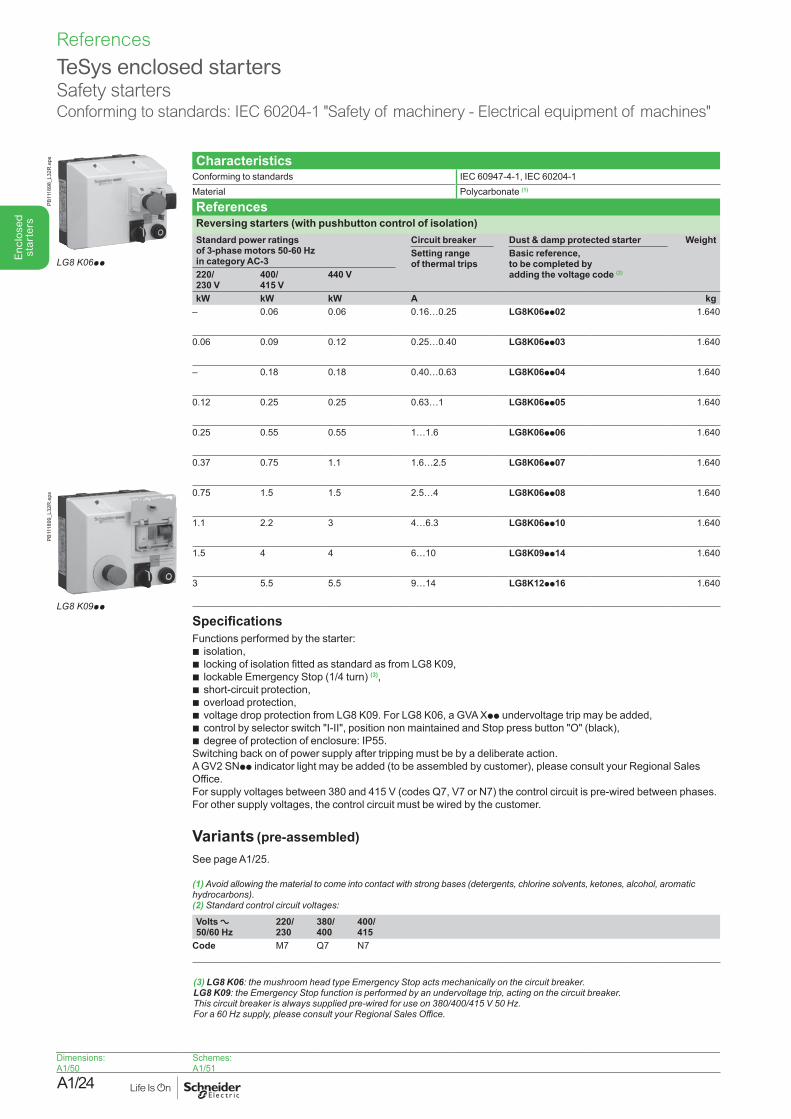
ReferencesReversing starters (with pushbutton control of isolation)Standard power ratings of 3-phase motors 50-60 Hz in category AC-3
Circuit breaker Dust & damp protected starter WeightSetting range of thermal trips
Basic reference, to be completed by adding the voltage code (2) 220/
230 V 400/ 415 V
440 V
kW kW kW A kg– 0.06 0.06 0.16…0.25 LG8K06pp02 1.640
0.06 0.09 0.12 0.25…0.40 LG8K06pp03 1.640
– 0.18 0.18 0.40…0.63 LG8K06pp04 1.640
0.12 0.25 0.25 0.63…1 LG8K06pp05 1.640
0.25 0.55 0.55 1…1.6 LG8K06pp06 1.640
0.37 0.75 1.1 1.6…2.5 LG8K06pp07 1.640
0.75 1.5 1.5 2.5…4 LG8K06pp08 1.640
1.1 2.2 3 4…6.3 LG8K06pp10 1.640
1.5 4 4 6…10 LG8K09pp14 1.640
3 5.5 5.5 9…14 LG8K12pp16 1.640
SpecificationsFunctions performed by the starter:b isolation,b locking of isolation fitted as standard as from LG8 K09,b lockable Emergency Stop (1/4 turn) (3),b short-circuit protection,b overload protection,b voltage drop protection from LG8 K09. For LG8 K06, a GVA Xpp undervoltage trip may be added,b control by selector switch "I-II", position non maintained and Stop press button "O" (black),b degree of protection of enclosure: IP55.Switching back on of power supply after tripping must be by a deliberate action.A GV2 SNpp indicator light may be added (to be assembled by customer), please consult your Regional Sales Office.For supply voltages between 380 and 415 V (codes Q7, V7 or N7) the control circuit is pre-wired between phases. For other supply voltages, the control circuit must be wired by the customer.
Variants (pre-assembled) See page A1/25.
(1) Avoid allowing the material to come into contact with strong bases (detergents, chlorine solvents, ketones, alcohol, aromatic hydrocarbons).(2) Standard control circuit voltages:
Volts a 50/60 Hz
220/ 230
380/ 400
400/ 415
Code M7 Q7 N7
(3) LG8 K06:themushroomheadtypeEmergencyStopactsmechanicallyonthecircuitbreaker. LG8 K09:theEmergencyStopfunctionisperformedbyanundervoltagetrip,actingonthecircuitbreaker. Thiscircuitbreakerisalwayssuppliedpre-wiredforuseon380/400/415V50Hz. Fora60Hzsupply,pleaseconsultyourRegionalSalesOffice.
PB11
1898
_L32
R.e
ps
LG8 K06pp
PB11
1899
_L32
R.e
ps
LG8 K09pp
Dimensions:A1/50
Schemes:A1/51
References
A1/25
Enc
lose
d st
arte
rs
TeSys enclosed startersSafety startersConforming to standards: IEC 60204-1 "Safety of machinery - Electrical equipment of machines"
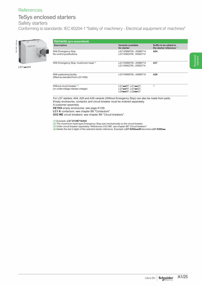
Variants (pre-assembled)Description Variants available
for starterSuffix to be added to the starter reference (1)
With Emergency StopNo control pushbuttons
LG7 K06M705...K09M714LG7 K06Q705...K09Q714
A04
With Emergency Stop, mushroom head (2) LG1 K06M705...K09M714LG1 K06Q705...K09Q714
A37
With padlocking facility(fitted as standard from LG7 K09)
LG7 K06M705...K06M710 A29
Without circuit breaker (3) (or undervoltage release voltage)
LG1ppM7, LG1ppQ7, LG7ppM7, LG7ppQ7, LG8ppM7, LG8ppQ7
(4)
For LG7 starters: A04, A29 and A39 variants (Without Emergency Stop) can also be made from parts. Empty enclosures, contactor and circuit breaker must be ordered separately.A customer assembly.DE1KS empty enclosures: see page A1/29.LC1 K contactors: see chapter B8 "Contactors".GV2 ME circuit breakers: see chapter B6 “Circuit breakers”.
(1) Example: LG7 D12M716A04.(2)ThemushroomheadtypeEmergencyStopactsmechanicallyonthecircuitbreaker.(3)Ordercircuitbreakerseparately.ReferencesGV2ME:seechapterB6“Circuitbeakers”.(4)Deletethelast2digitsoftheselectedstarterreference.Example:LG1 K065pp08 becomes LG1 K065pp.
LG7 ppA04
PB11
1887
_L32
R.e
ps
References
A1/26
Enc
lose
d st
arte
rs
TeSys enclosed starters Safety startersConforming to standards: IEC 60204-1 "Safety of machinery - Electrical equipment of machines"
CharacteristicsConforming to standards IEC 60947-4-1, IEC 60204-1
Material Polycarbonate (1)
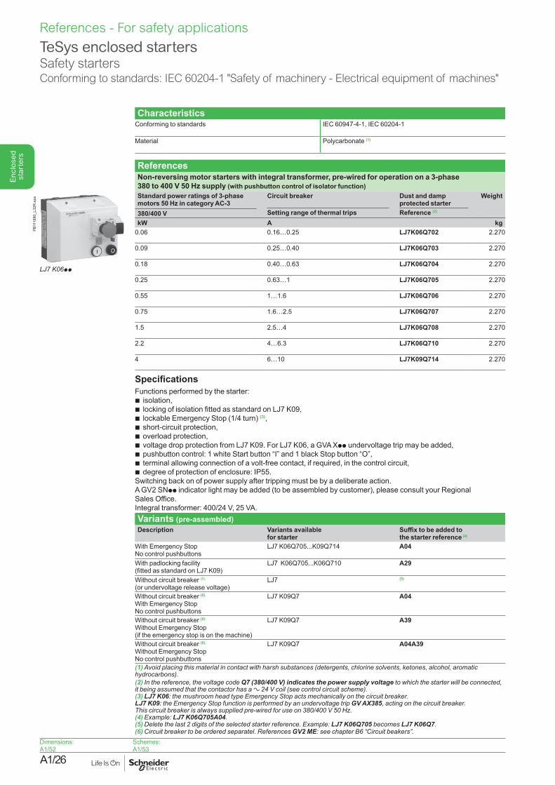
ReferencesNon-reversing motor starters with integral transformer, pre-wired for operation on a 3-phase 380 to 400 V 50 Hz supply (with pushbutton control of isolator function)Standard power ratings of 3-phase motors 50 Hz in category AC-3
Circuit breaker Dust and damp protected starter
Weight
Setting range of thermal trips Reference (2)380/400 VkW A kg
0.06 0.16…0.25 LJ7K06Q702 2.270
0.09 0.25…0.40 LJ7K06Q703 2.270
0.18 0.40…0.63 LJ7K06Q704 2.270
0.25 0.63…1 LJ7K06Q705 2.270
0.55 1…1.6 LJ7K06Q706 2.270
0.75 1.6…2.5 LJ7K06Q707 2.270
1.5 2.5…4 LJ7K06Q708 2.270
2.2 4…6.3 LJ7K06Q710 2.270
4 6…10 LJ7K09Q714 2.270
SpecificationsFunctions performed by the starter:b isolation,b locking of isolation fitted as standard on LJ7 K09,b lockable Emergency Stop (1/4 turn) (3),b short-circuit protection,b overload protection,b voltage drop protection from LJ7 K09. For LJ7 K06, a GVA Xpp undervoltage trip may be added,b pushbutton control: 1 white Start button “I” and 1 black Stop button “O”,b terminal allowing connection of a volt-free contact, if required, in the control circuit,b degree of protection of enclosure: IP55.Switching back on of power supply after tripping must be by a deliberate action.A GV2 SNpp indicator light may be added (to be assembled by customer), please consult your Regional Sales Office.Integral transformer: 400/24 V, 25 VA.Variants (pre-assembled)Description Variants available
for starterSuffix to be added to the starter reference (4)
With Emergency Stop No control pushbuttons
LJ7 K06Q705...K09Q714 A04
With padlocking facility (fitted as standard on LJ7 K09)
LJ7 K06Q705...K06Q710 A29
Without circuit breaker (6)
(or undervoltage release voltage)LJ7 (5)
Without circuit breaker (6)
With Emergency Stop No control pushbuttons
LJ7 K09Q7 A04
Without circuit breaker (6)
Without Emergency Stop (if the emergency stop is on the machine)
LJ7 K09Q7 A39
Without circuit breaker (6)
Without Emergency Stop No control pushbuttons
LJ7 K09Q7 A04A39
(1) Avoid placing this material in contact with harsh substances (detergents, chlorine solvents, ketones, alcohol, aromatic hydrocarbons).(2) In the reference, the voltage code Q7 (380/400 V) indicates the power supply voltage to which the starter will be connected, it being assumed that the contactor has a a24Vcoil(seecontrolcircuitscheme).(3) LJ7 K06:themushroomheadtypeEmergencyStopactsmechanicallyonthecircuitbreaker. LJ7 K09: the Emergency Stop function is performed by an undervoltage trip GV AX385,actingonthecircuitbreaker. Thiscircuitbreakerisalwayssuppliedpre-wiredforuseon380/400V50Hz.(4) Example: LJ7 K06Q705A04.(5)Deletethelast2digitsoftheselectedstarterreference.Example:LJ7 K06Q705 becomes LJ7 K06Q7.(6)Circuitbreakertobeorderedseparatel.ReferencesGV2 ME: seechapterB6“Circuitbeakers”.
LJ7 K06pp
PB11
1880
_L32
R.e
ps
Dimensions:A1/52
Schemes:A1/53
References - For safety applications
A1/27
Enc
lose
d st
arte
rs
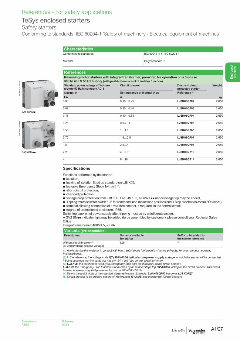
TeSys enclosed starters Safety startersConforming to standards: IEC 60204-1 "Safety of machinery - Electrical equipment of machines"
CharacteristicsConforming to standards IEC 60947-4-1, IEC 60204-1
Material Polycarbonate (1)
ReferencesReversing motor starters with integral transformer, pre-wired for operation on a 3-phase 380 to 400 V 50 Hz supply (with pushbutton control of isolator function)Standard power ratings of 3-phase motors 50 Hz in category AC-3
Circuit breaker Dust and damp protected starter
Weight
Setting range of thermal trips Reference (2)380/400 VkW A kg
0.06 0.16…0.25 LJ8K06Q702 2.650
0.09 0.25…0.40 LJ8K06Q703 2.650
0.18 0.40…0.63 LJ8K06Q704 2.650
0.25 0.63…1 LJ8K06Q705 2.650
0.55 1…1.6 LJ8K06Q706 2.650
0.75 1.6…2.5 LJ8K06Q707 2.650
1.5 2.5…4 LJ8K06Q708 2.650
2.2 4…6.3 LJ8K06Q710 2.650
4 6…10 LJ8K09Q714 2.650
SpecificationsFunctions performed by the starter:b isolation,b locking of isolation fitted as standard on LJ8 K09,b lockable Emergency Stop (1/4 turn) (3),b short-circuit protection,b overload protection,b voltage drop protection from LJ8 K09. For LJ8 K06, a GVA Xpp undervoltage trip may be added,b 1 spring return selector switch "I-II" for command, non-maintained positions and 1 Stop pushbutton control "O" (black),b terminal allowing connection of a volt-free contact, if required, in the control circuit,b degree of protection of enclosure: IP55.Switching back on of power supply after tripping must be by a deliberate action.A GV2 SNpp indicator light may be added (to be assembled by customer), please consult your Regional Sales Office.Integral transformer: 400/24 V, 25 VA.
Variants (pre-assembled)Description Variants available
for starterSuffix to be added to the starter reference
Without circuit breaker (5)
(or undervoltage release voltage)LJ8 (4)
(1) Avoid placing this material in contact with harsh substances (detergents, chlorine solvents, ketones, alcohol, aromatic hydrocarbons).(2) In the reference, the voltage code Q7 (380/400 V) indicates the power supply voltage to which the starter will be connected, it being assumed that the contactor has a a24Vcoil(seecontrolcircuitscheme).(3) LJ8 K06:themushroomheadtypeEmergencyStopactsmechanicallyonthecircuitbreaker. LJ8 K09: the Emergency Stop function is performed by an undervoltage trip GV AX385,actingonthecircuitbreaker.Thiscircuitbreakerisalwayssuppliedpre-wiredforuseon380/400V50Hz.(4)Deletethelast2digitsoftheselectedstarterreference.Example:LJ8 K06Q702 becomes LJ8 K06Q7. (5)Circuitbreakertobeorderedseparatel.ReferencesGV2 ME: seechapterB6“Circuitbeakers”.
LJ8 K06pp
PB11
1898
_L32
R.e
psPB
1118
99_L
32R
.eps
LJ8 K09pp
Dimensions:A1/52
Schemes:A1/53
References - For safety applications
A1/28
Enc
lose
d st
arte
rs
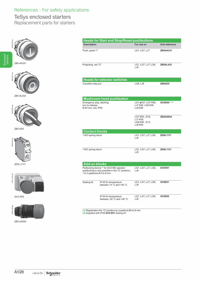
Heads for Start and Stop/Reset pushbuttonsDescription For use on Unit reference
Flush, green “I” LG1, LG7, LJ7 ZB5AA331
Projecting, red “O” LG1, LG7, LJ7, LG8, LJ8
ZB5AL432
Heads for selector switches3-position stay put LG8, LJ8 ZB5AD5
Mushroom head pushbuttonEmergency stop, latching,turn to release,Ø 40 mm, red, IP55
LG1 pA37, LG7 K06, LJ7 K06, LG8 K06, LJ8 K06
GV2K04 (1) (2)
LG7 K09...D18, LJ7 K09, LG8 K09...K12, LJ8 K09
ZB5AS834
Contact blocks1 N/O spring return LG1, LG7, LJ7, LG8,
LJ8ZENL1111
1 N/C spring return LG1, LG7, LJ7, LG8, LJ8
ZENL1121
Add-on blocksPadlocking device (2) for GV2 ME operator (padlocking is only possible in the “O” position),1 to 3 padlocks Ø 4 to 8 mm
LG1, LG7, LJ7, LG8, LJ8
GV2V01
Sealing kit IP 55 for temperature between +5 °C and +40 °C
LG1, LG7, LJ7, LG8, LJ8
GV2E01
IP 55 for temperature between -20 °C and +40 °C
LG1, LG7, LJ7, LG8, LJ8
GV2E02
(1) Registration the “O” position by a padlock Ø4 to 8 mm.(2)SuppliedwithIP55GV2 E01 sealingkit.
TeSys enclosed starters Replacement parts for starters
ZB5AL432
DB4
0345
1.ep
s
ZB5AD5
DB4
0345
3.ep
s
ZENL1111
DB4
0345
4.ep
sD
B403
450.
eps
ZB5AA331
8274
_L32
R.e
ps
GV2 K04
1103
49_L
32R.
eps
ZB5AS834
References - For safety applications
A1/29
Enc
lose
d st
arte
rs
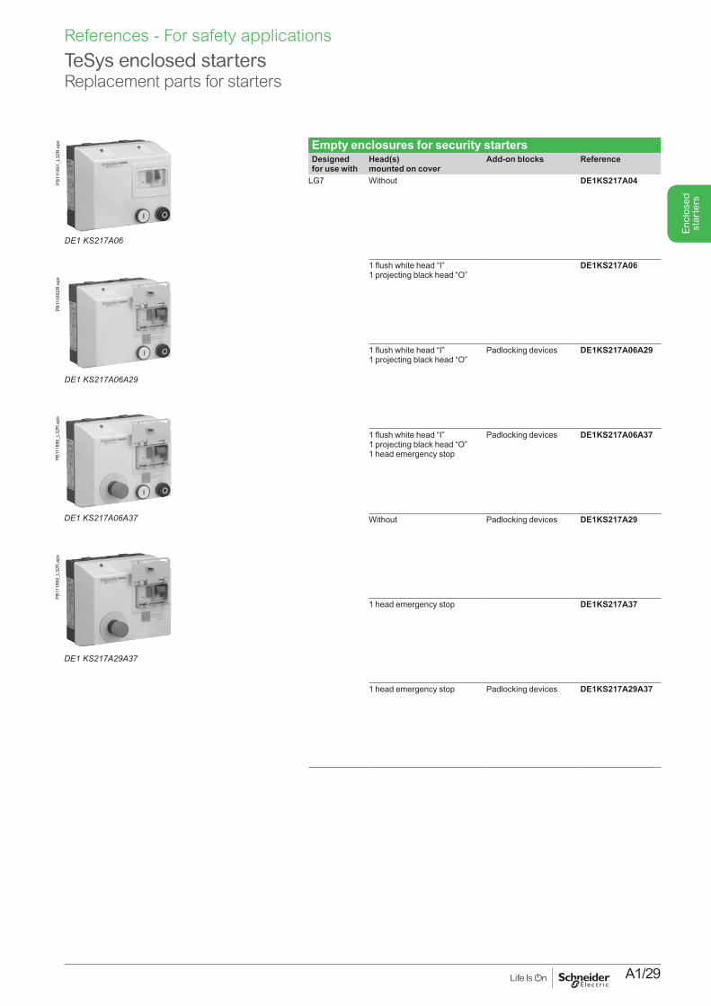
Empty enclosures for security startersDesigned for use with
Head(s) mounted on cover
Add-on blocks Reference
LG7 Without DE1KS217A04
1 flush white head “I” 1 projecting black head “O”
DE1KS217A06
1 flush white head “I” 1 projecting black head “O”
Padlocking devices DE1KS217A06A29
1 flush white head “I” 1 projecting black head “O”1 head emergency stop
Padlocking devices DE1KS217A06A37
Without Padlocking devices DE1KS217A29
1 head emergency stop DE1KS217A37
1 head emergency stop Padlocking devices DE1KS217A29A37
TeSys enclosed starters Replacement parts for starters
DE1 KS217A06A37
PB11
1886
_L32
R.e
ps
DE1 KS217A29A37
PB11
1889
_L32
R.e
ps
DE1 KS217A06
PB11
1891
_L32
R.e
ps
DE1 KS217A06A29
PB11
1892
R.e
ps
References - For safety applications
A1/30
Enc
lose
d st
arte
rsReferences - Starters for AS-interface bus
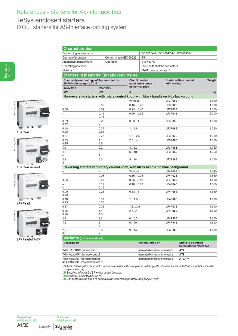
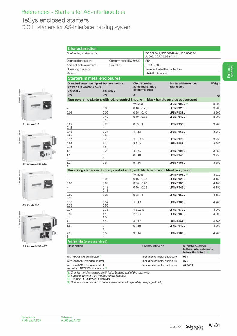
CharacteristicsConforming to standards IEC 60204-1, IEC 60947-4-1, IEC 60439-1Degree of protection Conforming to IEC 60529 IP54Ambient air temperature Operation -5 to +40 °COperating positions Same as that of the contactorsMaterial LFp P: polycarbonate (1)
Starters in insulated (plastic) enclosureStandard power ratings of 3-phase motors 50-60 Hz in category AC-3
Circuit breaker adjustment range of thermal trips
Starter with extended addressing
Weight
220/230 V 400/415 VkW kW A kgNon-reversing starters with rotary control knob, with black handle on blue background
– – Without LF3P00E (2) 1.020– 0.06 0.16…0.25 LF3P02E 1.3000.06 0.09 0.25…0.40 LF3P03E 1.300––
0.120.18
0.40…0.63 LF3P04E 1.300
0.090.12
0.25–
0.63…1 LF3P05E 1.300
0.180.25
0.370.55
1…1.6 LF3P06E 1.350
0.37 0.75 1.6…2.5 LF3P07E 1.3500.550.75
1.11.5
2.5…4 LF3P08E 1.350
1.1 2.2 4…6.3 LF3P10E 1.3501.5–
34
6…10 LF3P14E 1.350
2.23
5.5–
9…14 LF3P16E 1.350
Reversing starters with rotary control knob, with black handle on blue background– – Without LF4P00E (2) 1.020– 0.06 0.16…0.25 LF4P02E 1.5500.06 0.09 0.25…0.40 LF4P03E 1.550––
0.120.18
0.40…0.63 LF4P04E 1.550
0.090.12
0.25–
0.63…1 LF4P05E 1.550
0.180.25
0.370.55
1…1.6 LF4P06E 1.600
0.37 0.75 1.6…2.5 LF4P07E 1.6000.550.75
1.11.5
2.5…4 LF4P08E 1.600
1.1 2.2 4…6.3 LF4P10E 1.6001.5–
34
6…10 LF4P14E 1.600
2.23
5.5–
9…14 LF4P16E 1.600
Variants (pre-assembled)Description For mounting on Suffix to be added
to the starter reference (3)
With HARTING connectors (4) Insulated or metal enclosure A74With local/AS-Interface control Insulated or metal enclosure A79With local/AS-Interface control and with HARTING connectors (4)
Insulated or metal enclosure A79A74
(1) Avoid allowing the material to come into contact with strong bases (detergents, chlorine solvents, ketones, alcohol, aromatic hydrocarbons).
(2)SuppliedwithoutGV2Pmotorcircuitbreaker.(3) Example: LF3 P02EA79A74.(4)Connectorstobefittedtocables(tobeorderedseparately,seepageA1/69).
TeSys enclosed startersD.O.L. starters for AS-Interface cabling system
LF3 PppE
PB11
2223
_L30
R.e
psPB
1122
24_L
30.e
ps
LF4 PppE
LF3 PppEA79A74
PB11
2235
_L30
.eps
LF4 PppEA79A74
PB11
2236
R.e
ps
Dimensions:A1/64 and A1/65
Schemes:A1/66 and A1/67
A1/31
Enc
lose
d st
arte
rs
References - Starters for AS-interface bus
TeSys enclosed startersD.O.L. starters for AS-Interface cabling system
CharacteristicsConforming to standards IEC 60204-1, IEC 60947-4-1, IEC 60439-1
UL 508, CSA C22-2 n° 14 (1)
Degree of protection Conforming to IEC 60529 IP54Ambient air temperature Operation -5 to +40 °COperating positions Same as that of the contactorsMaterial LFp MP: sheet steel
Starters in metal enclosuresStandard power ratings of 3-phase motors 50-60 Hz in category AC-3
Circuit breaker adjustment range of thermal trips
Starter with extended addressing
Weight
220/230 V 400/415 VkW kW A kgNon-reversing starters with rotary control knob, with black handle on blue background
– – Without LF3MP00EU (2) 3.620– 0.06 0.16…0.25 LF3MP02EU 3.9000.06 0.09 0.25…0.40 LF3MP03EU 3.900––
0.120.18
0.40…0.63 LF3MP04EU 3.900
0.090.12
0.25–
0.63…1 LF3MP05EU 3.900
0.180.25
0.370.55
1…1.6 LF3MP06EU 3.950
0.37 0.75 1.6…2.5 LF3MP07EU 3.9500.550.75
1.11.5
2.5…4 LF3MP08EU 3.950
1.1 2.2 4…6.3 LF3MP10EU 3.9501.5–
34
6…10 LF3MP14EU 3.950
2.23
5.5–
9…14 LF3MP16EU 3.950
Reversing starters with rotary control knob, with black handle on blue background – – Without LF4MP00EU (2) 3.620– 0.06 0.16…0.25 LF4MP02EU 4.1500.06 0.09 0.25…0.40 LF4MP03EU 4.150––
0.120.18
0.40…0.63 LF4MP04EU 4.150
0.090.12
0.25–
0.63…1 LF4MP05EU 4.150
0.180.25
0.370.55
1…1.6 LF4MP06EU 4.200
0.37 0.75 1.6…2.5 LF4MP07EU 4.2000.550.75
1.11.5
2.5…4 LF4MP08EU 4.200
1.1 2.2 4…6.3 LF4MP10EU 4.2001.5–
34
6…10 LF4MP14EU 4.200
2.23
5.5–
9…14 LF4MP16EU 4.200
Variants (pre-assembled)Description For mounting on Suffix to be added
to the starter reference, before the letter U (3)
With HARTING connectors (4) Insulated or metal enclosure A74With local/AS-Interface control Insulated or metal enclosure A79With local/AS-Interface control and with HARTING connectors (4)
Insulated or metal enclosure A79A74
(1) Only for metal enclosures with letter Uattheendofthereference.(2)SuppliedwithoutGV2Pmotorcircuitbreaker.(3) Example: LF3 MP02EA79A74U.(4)Connectorstobefittedtocables(tobeorderedseparately,seepageA1/69).
LF4 MPppA79A74U
PB11
2238
_L32
R.e
ps
LF3 MPppEU
PB11
2225
_L32
R.e
psPB
1122
37_L
30.e
ps
LF3 MPppA79A7AU
LF4 MPppEU
PB11
2226
_L30
.eps
Dimensions:A1/64 and A1/65
Schemes:A1/66 and A1/67
A1/32
Enc
lose
d st
arte
rsReferences - Starters for AS-interface bus
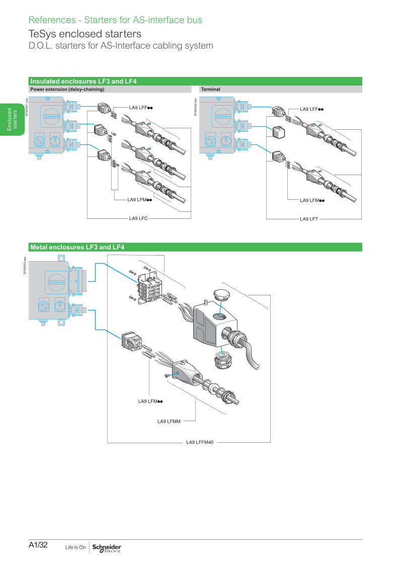
Insulated enclosures LF3 and LF4Power extension (daisy-chaining) Terminal
LA9 LFF
LA9 LFC
LA9 LFM
DF5
6525
1.ep
s
LA9 LFF
LA9 LFT
LA9 LFMD
F565
252.
eps
Metal enclosures LF3 and LF4
LA9 LFFM40
LA9 LFMM
LA9 LFM
DF5
6525
3.ep
s
TeSys enclosed startersD.O.L. starters for AS-Interface cabling system
A1/33
Enc
lose
d st
arte
rs
References - Starters for AS-interface bus
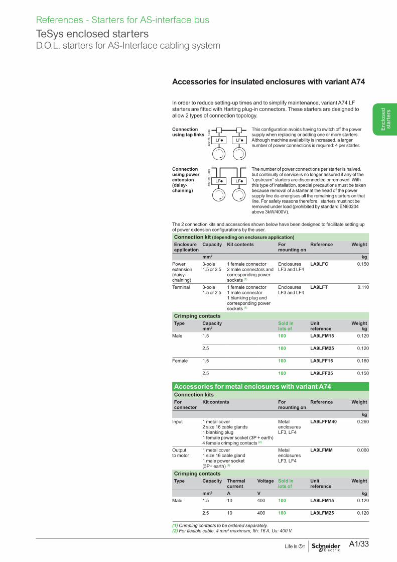
Accessories for insulated enclosures with variant A74PresentationIn order to reduce setting-up times and to simplify maintenance, variant A74 LF starters are fitted with Harting plug-in connectors. These starters are designed to allow 2 types of connection topology.
Connection using tap links
LF LF
5001
75_1
.eps This configuration avoids having to switch off the power
supply when replacing or adding one or more starters. Although machine availability is increased, a larger number of power connections is required: 4 per starter.
Connection using power extension (daisy-chaining)
LF LF
5001
76_1
.eps The number of power connections per starter is halved,
but continuity of service is no longer assured if any of the “upstream” starters are disconnected or removed. With this type of installation, special precautions must be taken because removal of a starter at the head of the power supply line de-energises all the remaining starters on that line. For safety reasons therefore, starters must not be removed under load (prohibited by standard EN60204 above 3kW/400V).
The 2 connection kits and accessories shown below have been designed to facilitate setting up of power extension configurations by the user.Connection kit (depending on enclosure application) Enclosure application
Capacity Kit contents For mounting on
Reference Weight
mm2 kgPower extension (daisy-chaining)
3-pole 1.5 or 2.5
1 female connector 2 male connectors and corresponding power sockets (1)
Enclosures LF3 and LF4
LA9LFC 0.150
Terminal 3-pole 1.5 or 2.5
1 female connector 1 male connector 1 blanking plug and corresponding power sockets (1)
Enclosures LF3 and LF4
LA9LFT 0.110
Crimping contactsType Capacity
mm2Sold in lots of
Unit reference
Weightkg
Male 1.5 100 LA9LFM15 0.120
2.5 100 LA9LFM25 0.120
Female 1.5 100 LA9LFF15 0.160
2.5 100 LA9LFF25 0.150
Accessories for metal enclosures with variant A74Connection kits For connector
Kit contents For mounting on
Reference Weight
kgInput 1 metal cover
2 size 16 cable glands 1 blanking plug 1 female power socket (3P + earth) 4 female crimping contacts (2)
Metal enclosures LF3, LF4
LA9LFFM40 0.260
Output to motor
1 metal cover 1 size 16 cable gland 1 male power socket (3P+ earth) (1)
Metal enclosures LF3, LF4
LA9LFMM 0.060
Crimping contactsType Capacity Thermal
currentVoltage Sold in
lots ofUnit reference
Weight
mm2 A V kgMale 1.5 10 400 100 LA9LFM15 0.120
2.5 10 400 100 LA9LFM25 0.120
(1)Crimpingcontactstobeorderedseparately.(2)Forflexiblecable,4mm2maximum,Ith:16A,Us:400V.
TeSys enclosed startersD.O.L. starters for AS-Interface cabling system

A1/34

A1/35
Enc
lose
d st
arte
rs
Technical Data for Designers
Enc
lose
d st
arte
rs
ContentsSwitch-disconnectors ........................ A1/36 to A1/38Direct-on-line starters ......................... A1/39 to A1/47Star-delta starters ............................... A1/48 to A1/49Starters for safety applications ........... A1/50 to A1/53Starters for AS-interface bus ............... A1/54 to A1/69
A1/36
Enc
lose
d st
arte
rs
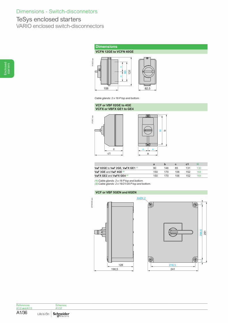
DimensionsVCFN 12GE to VCFN 40GE
82,5106
131
90
==
8128
22.e
ps
Cableglands:2x16Ptopandbottom.
VCF or VBF 02GE to 4GEVCFX or VBFX GE1 to GE4
c
c1
b
a
= =
H
8128
21.e
ps
a b c c1 HVpF 02GE to VpF 2GE, VpFX GE1 (1) 90 146 85 131 130VpF 3GE and VpF 4GE (2) 150 170 106 152 164VpFX GE2 and VpFX GE4 (2) 150 170 106 152 164
(1)Cableglands:2x16Ptopandbottom.(2)Cableglands:2x16/21/29Ptopandbottom.
VCF or VBF 5GEN and 6GEN
218,5
241
268,
5=
=
29
1
128
190,5
4xØ4,2
DF5
6939
5.ep
s
References:A1/2 and A1/3
Schemes:A1/37
TeSys enclosed startersVARIO enclosed switch-disconnectors
Dimensions - Switch-disconnetors
A1/37
Enc
lose
d st
arte
rs
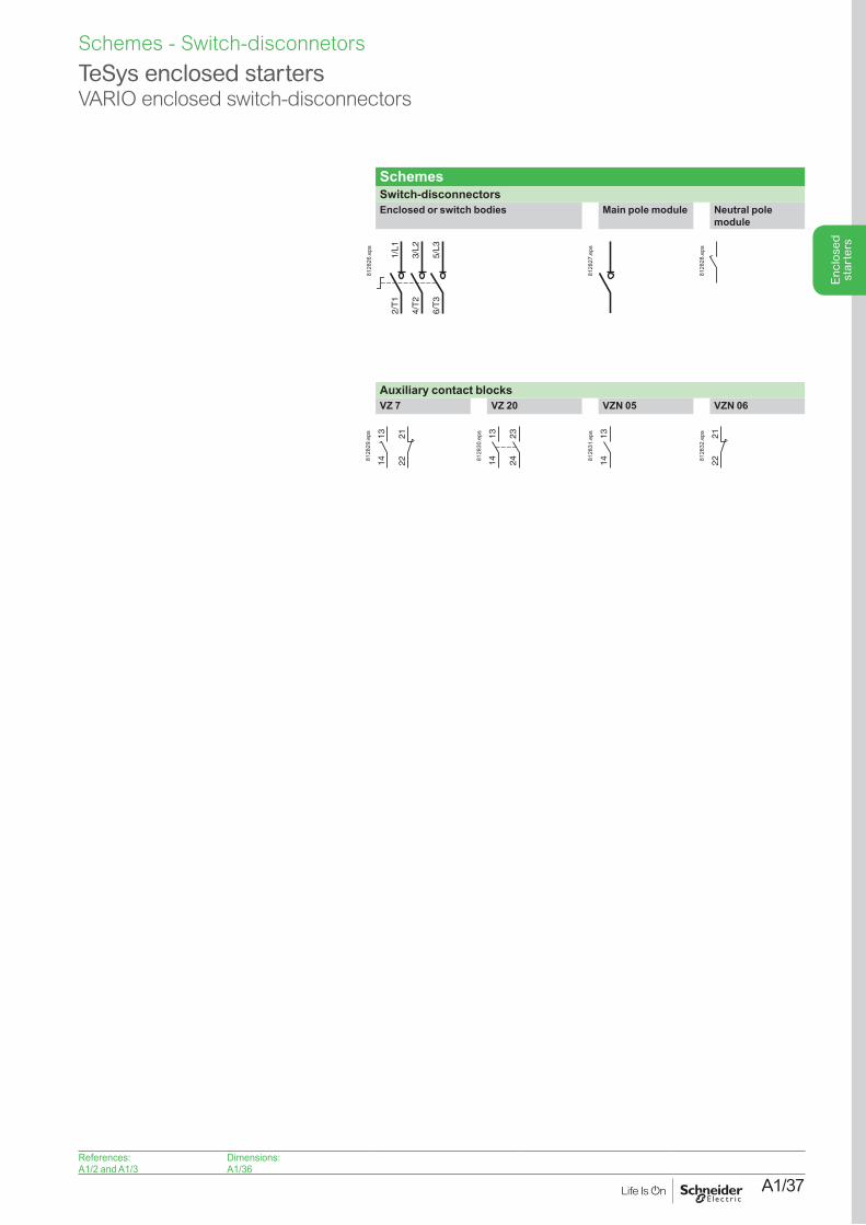
SchemesSwitch-disconnectorsEnclosed or switch bodies Main pole module Neutral pole
module
1/L1
2/T
1
3/L2
4/T
2
5/L3
6/T
3
8128
26.e
ps
8128
27.e
ps
8128
28.e
ps
Auxiliary contact blocksVZ 7 VZ 20 VZN 05 VZN 06
222113
148128
29.e
ps 1314 24
23
8128
30.e
ps 131481
2831
.eps
2221
8128
32.e
ps
TeSys enclosed startersVARIO enclosed switch-disconnectors
References:A1/2 and A1/3
Dimensions: A1/36
Schemes - Switch-disconnetors
A1/38
Enc
lose
d st
arte
rs
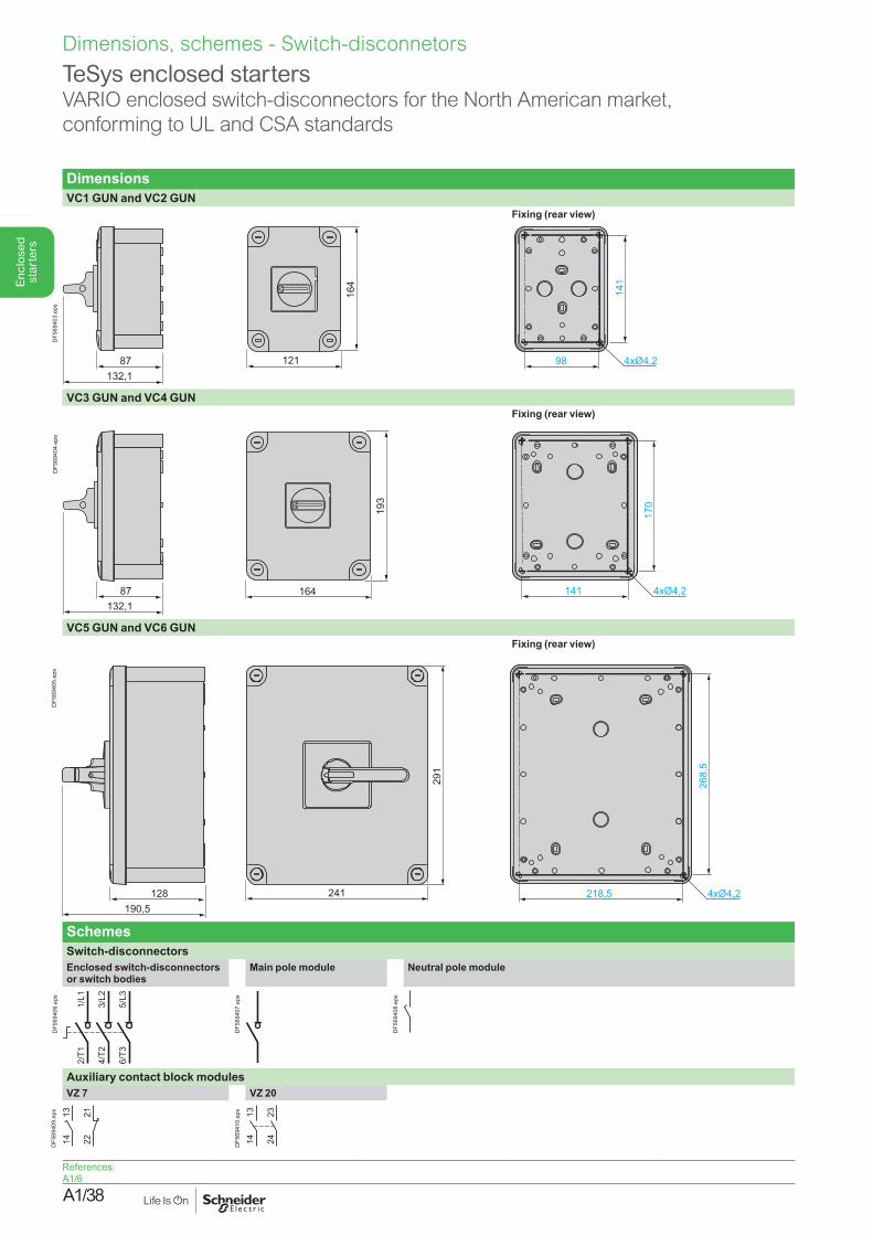
TeSys enclosed startersVARIO enclosed switch-disconnectors for the North American market, conforming to UL and CSA standards
DimensionsVC1 GUN and VC2 GUN
Fixing (rear view)
12187132,1
164
98
141
4xØ4,2
DF5
6940
3.ep
s
VC3 GUN and VC4 GUNFixing (rear view)
87132,1
164
193
141
170
4xØ4,2
DF5
6940
4.ep
s
VC5 GUN and VC6 GUNFixing (rear view)
128190,5
218,5241
268,
5
291
4xØ4,2
DF5
6940
5.ep
s
SchemesSwitch-disconnectorsEnclosed switch-disconnectors or switch bodies
Main pole module Neutral pole module
1/L1
2/T1
3/L2
4/T2
5/L3
6/T3
DF5
6940
6.ep
s
DF5
6940
7.ep
s
DF5
6940
8.ep
s
Auxiliary contact block modulesVZ 7 VZ 20
222113
14DF5
6940
9.ep
s 1314 24
23
DF5
6941
0.ep
s
References:A1/6
Dimensions, schemes - Switch-disconnetors
A1/39
Enc
lose
d st
arte
rs
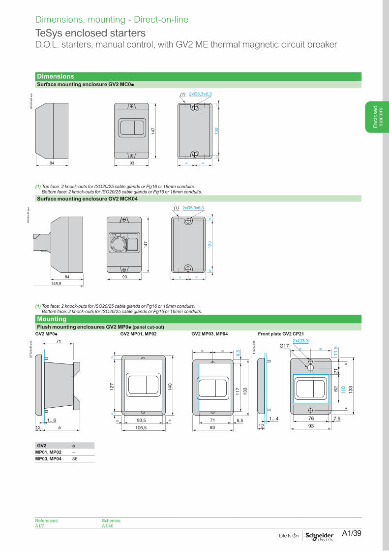
TeSys enclosed startersD.O.L. starters, manual control, with GV2 ME thermal magnetic circuit breaker
DimensionsSurface mounting enclosure GV2 MC0p
147
84
(1)
93 =
130
==
=
DF5
2344
3.ep
s
(1)Topface:2knock-outsforISO20/25cableglandsorPg16or16mmconduits. Bottomface:2knock-outsforISO20/25cableglandsorPg16or16mmconduits.
Surface mounting enclosure GV2 MCK04
147
84
145,5
(1)
=
130
==
=93
DF5
2344
4.ep
s
(1)Topface:2knock-outsforISO20/25cableglandsorPg16or16mmconduits. Bottomface:2knock-outsforISO20/25cableglandsorPg16or16mmconduits.
MountingFlush mounting enclosures GV2 MP0p (panel cut-out)
GV2 MP0p GV2 MP01, MP02 GV2 MP03, MP04 Front plate GV2 CP21
1...6
a12
140
=12
7=
= 93,5 =
106,5
71
93
6,5
117
133
71
= =
9,5
DF5
2344
5.ep
s
1...4
12
76
93
7,5
118
21
133
= =
6211
,5
8122
02.e
ps
GV2 aMP01, MP02 –MP03, MP04 86
References:A1/7
Schemes: A1/40
Dimensions, mounting - Direct-on-line
A1/40
Enc
lose
d st
arte
rs
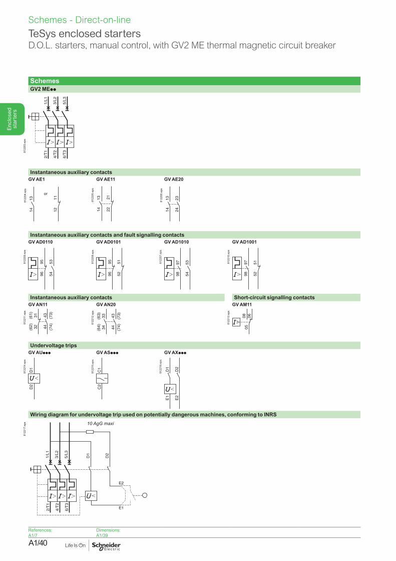
TeSys enclosed startersD.O.L. starters, manual control, with GV2 ME thermal magnetic circuit breaker
SchemesGV2 MEpp
2/T
1
4/T
2
6/T
3
1/L1
3/L2
5/L3
8122
03.e
ps
Instantaneous auxiliary contactsGV AE1
1314 12
11
or
8122
04.e
ps
GV AE11
1314 22
21
8122
05.e
ps
GV AE20
1314
2324
8122
06.e
ps
Instantaneous auxiliary contacts and fault signalling contactsGV AD0110 GV AD0101 GV AD1010 GV AD1001
535496
958122
09.e
ps
5251
969581
2208
.eps
9798
5354
8122
07.e
ps
9798
5152
8122
10.e
ps
Instantaneous auxiliary contacts Short-circuit signalling contactsGV AN11 GV AN20 GV AM11
(62) 32
(61) 31 43 (73)
44 (74)
8122
11.e
ps
(64) 34
(63) 33 43 (73)
44 (74)
8122
12.e
ps
050608
8122
13.e
ps
Undervoltage tripsGV AUppp GV ASppp GV AXppp
D1
D2
8122
14.e
ps
C1
C2
8122
15.e
ps
D1
D2
E1
E2
8122
16.e
ps
Wiring diagram for undervoltage trip used on potentially dangerous machines, conforming to INRS
2/T
1
4/T
2
6/T
3
1/L1
3/L2
5/L3
D1
D2
E2
E1
10 AgG maxi
8122
17.e
ps
References:A1/7
Dimensions: A1/39
Schemes - Direct-on-line
A1/41
Enc
lose
d st
arte
rs
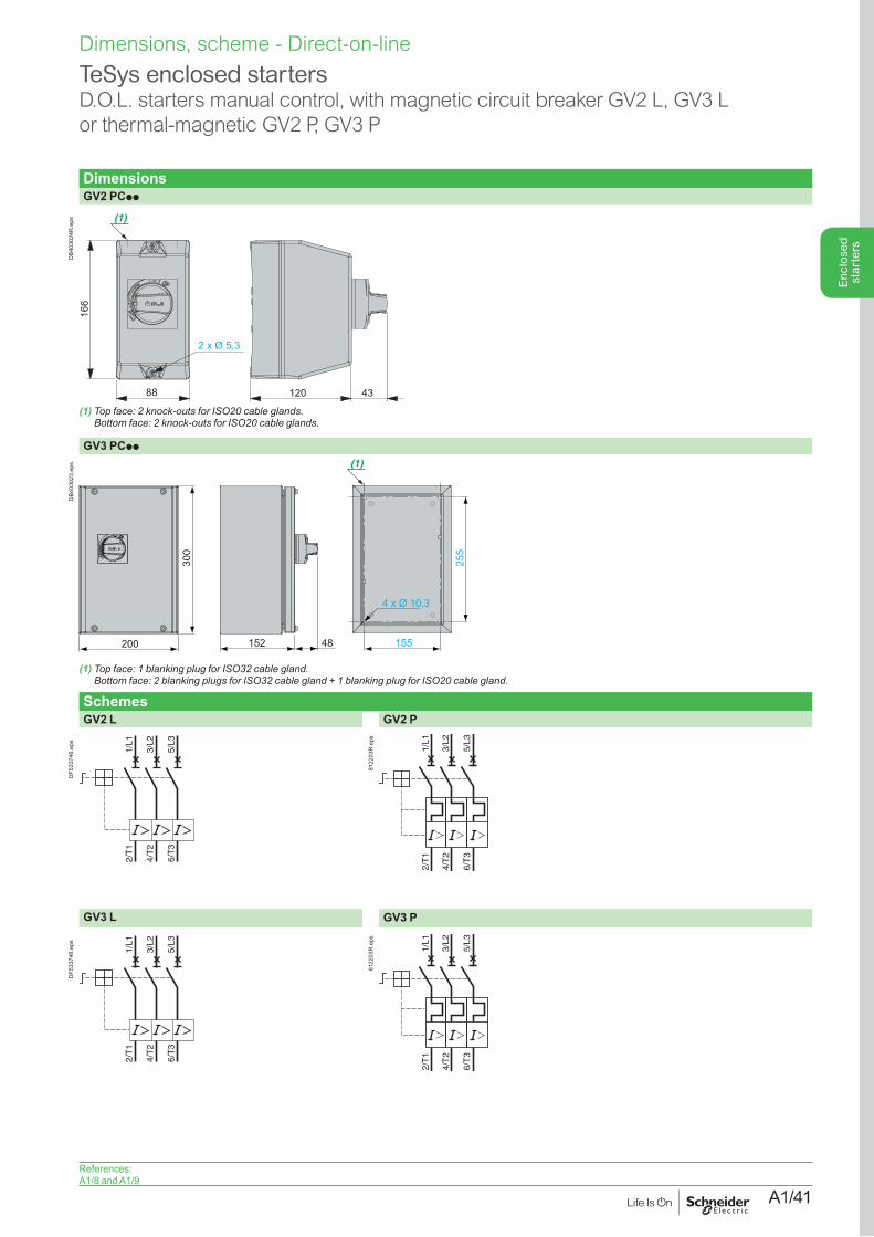
DimensionsGV2 PCpp
166
88 120 43
2 x Ø 5,3
(1)
DB4
0302
4R.e
ps
(1)Topface:2knock-outsforISO20cableglands. Bottomface:2knock-outsforISO20cableglands.
GV3 PCpp
152 48 155 200
300
255
4 x Ø 10,3
(1)
DB4
0302
3.ep
s
(1)Topface:1blankingplugforISO32cablegland. Bottomface:2blankingplugsforISO32cablegland+1blankingplugforISO20cablegland.
SchemesGV2 L GV2 P
2/T
1
4/T
2
6/T
3
1/L1
3/L2
5/L3
DF5
3374
6.ep
s
2/T
1
4/T
2
6/T
3
1/L1
3/L2
5/L3
8122
03R
.eps
GV3 L GV3 P
2/T
1
4/T
2
6/T
3
1/L1
3/L2
5/L3
DF5
3374
6.ep
s
2/T
1
4/T
2
6/T
3
1/L1
3/L2
5/L3
8122
03R
.eps
TeSys enclosed startersD.O.L. starters manual control, with magnetic circuit breaker GV2 L, GV3 L or thermal-magnetic GV2 P, GV3 P
References:A1/8 and A1/9
Dimensions, scheme - Direct-on-line
A1/42
Enc
lose
d st
arte
rs
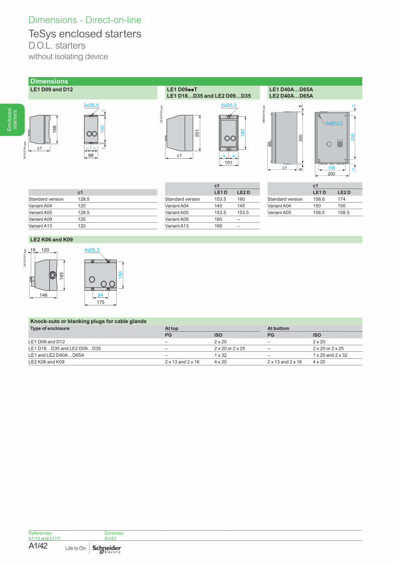
TeSys enclosed starters D.O.L. starterswithout isolating device
DimensionsLE1 D09 and D12 LE1 D09ppT
LE1 D18…D35 and LE2 D09…D35LE1 D40A…D65A LE2 D40A…D65A
c1
166
150
==
=
88
=
DF5
3375
4.ep
s
c1
183
= =
101
201
DF5
3375
5.ep
s
255
155 200
c1
300
6
6 =
4xØ10,3
=
DB4
0301
8.ep
s
c1 c1c1 LE1 D LE2 D LE1 D LE2 D
Standard version 128.5 Standard version 153.5 160 Standard version 158.5 174Variant A04 120 Variant A04 145 145 Variant A04 150 150Variant A05 128.5 Variant A05 153.5 153.5 Variant A05 158.5 158.5Variant A09 120 Variant A09 160 –Variant A13 120 Variant A13 160 –
LE2 K06 and K09
146
120
84
175
150
165
19
DF5
3375
7.ep
s
Knock-outs or blanking plugs for cable glandsType of enclosure At top At bottom
PG ISO PG ISOLE1 D09 and D12 – 2 x 20 – 2 x 20LE1 D18…D35 and LE2 D09…D35 – 2 x 20 or 2 x 25 – 2 x 20 or 2 x 25LE1 and LE2 D40A…D65A – 1 x 32 – 1 x 20 and 2 x 32LE2 K06 and K09 2 x 13 and 2 x 16 4 x 20 2 x 13 and 2 x 16 4 x 20
References:A1/10 and A1/11
Schemes:A1/43
Dimensions - Direct-on-line
A1/43
Enc
lose
d st
arte
rs
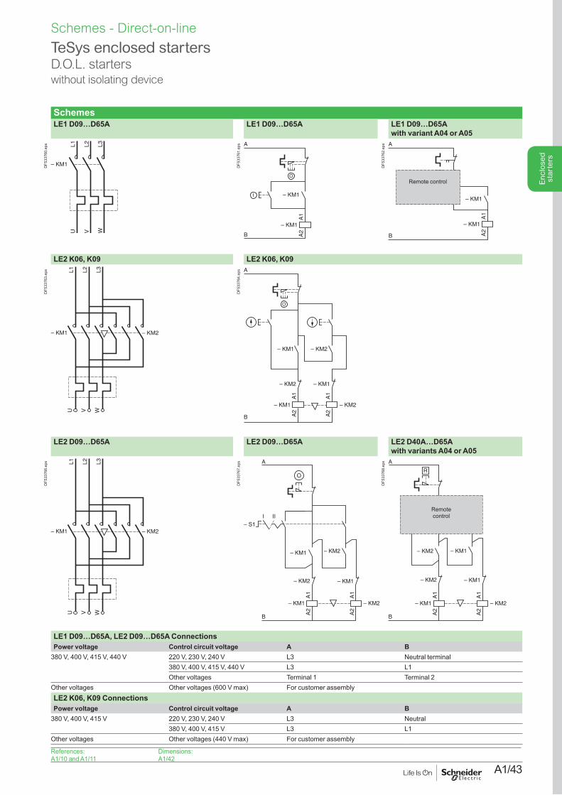
TeSys enclosed starters D.O.L. starterswithout isolating device
SchemesLE1 D09…D65A LE1 D09…D65A LE1 D09…D65A
with variant A04 or A05
L1 L2
– KM1
U V WL3
DF5
3376
0.ep
s
B
A
A1
A2
– KM1
– KM1
O
I
DF5
3376
1.ep
s
1314
2122
A
O
l– KM1
B
A1
A2
– KM1
Remote control
DF5
3376
2.ep
s
LE2 K06, K09 LE2 K06, K09
– KM1 – KM2
L1 L2 L3
U V W
DF5
3376
3.ep
s
– KM2
A
B
– KM1
– KM2– KM1
– KM2 – KM1
A1
A2
A1
A2
O
DF5
3376
4.ep
s
LE2 D09…D65A LE2 D09…D65A LE2 D40A…D65A with variants A04 or A05
– KM1 – KM2
L1 L2 L3
U V W
DF5
3376
6.ep
s
A1
A2
– KM1
– KM2
– KM2
A
A1
A2
– KM2
– KM1
B
– KM1
– S1III
DF5
3376
7.ep
s
– KM2
A1
A2
– KM1
2122
– KM2
A
O
A1
A2
– KM2
– KM1
B
R
l l
– KM1
Remote control
DF5
3376
8.ep
s
LE1 D09…D65A, LE2 D09…D65A ConnectionsPower voltage Control circuit voltage A B
380 V, 400 V, 415 V, 440 V 220 V, 230 V, 240 V L3 Neutral terminal380 V, 400 V, 415 V, 440 V L3 L1Other voltages Terminal 1 Terminal 2
Other voltages Other voltages (600 V max) For customer assemblyLE2 K06, K09 ConnectionsPower voltage Control circuit voltage A B
380 V, 400 V, 415 V 220 V, 230 V, 240 V L3 Neutral380 V, 400 V, 415 V L3 L1
Other voltages Other voltages (440 V max) For customer assembly
References:A1/10 and A1/11
Dimensions:A1/42
Schemes - Direct-on-line
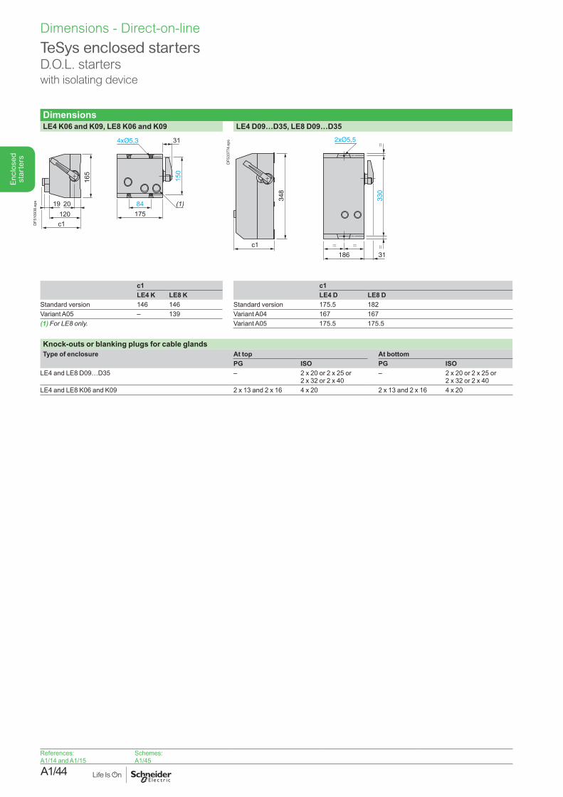
A1/44
Enc
lose
d st
arte
rs
TeSys enclosed startersD.O.L. starterswith isolating device
DimensionsLE4 K06 and K09, LE8 K06 and K09 LE4 D09…D35, LE8 D09…D35
c1
20 84175
150
165
(1)120
19
31
DF5
1093
8.ep
s
c1
348
330
==
=
186 31
=
DF5
3377
4.ep
s
c1 c1LE4 K LE8 K LE4 D LE8 D
Standard version 146 146 Standard version 175.5 182Variant A05 – 139 Variant A04 167 167(1)ForLE8only. Variant A05 175.5 175.5
Knock-outs or blanking plugs for cable glandsType of enclosure At top At bottom
PG ISO PG ISOLE4 and LE8 D09…D35 – 2 x 20 or 2 x 25 or
2 x 32 or 2 x 40– 2 x 20 or 2 x 25 or
2 x 32 or 2 x 40LE4 and LE8 K06 and K09 2 x 13 and 2 x 16 4 x 20 2 x 13 and 2 x 16 4 x 20
References:A1/14 and A1/15
Schemes:A1/45
Dimensions - Direct-on-line
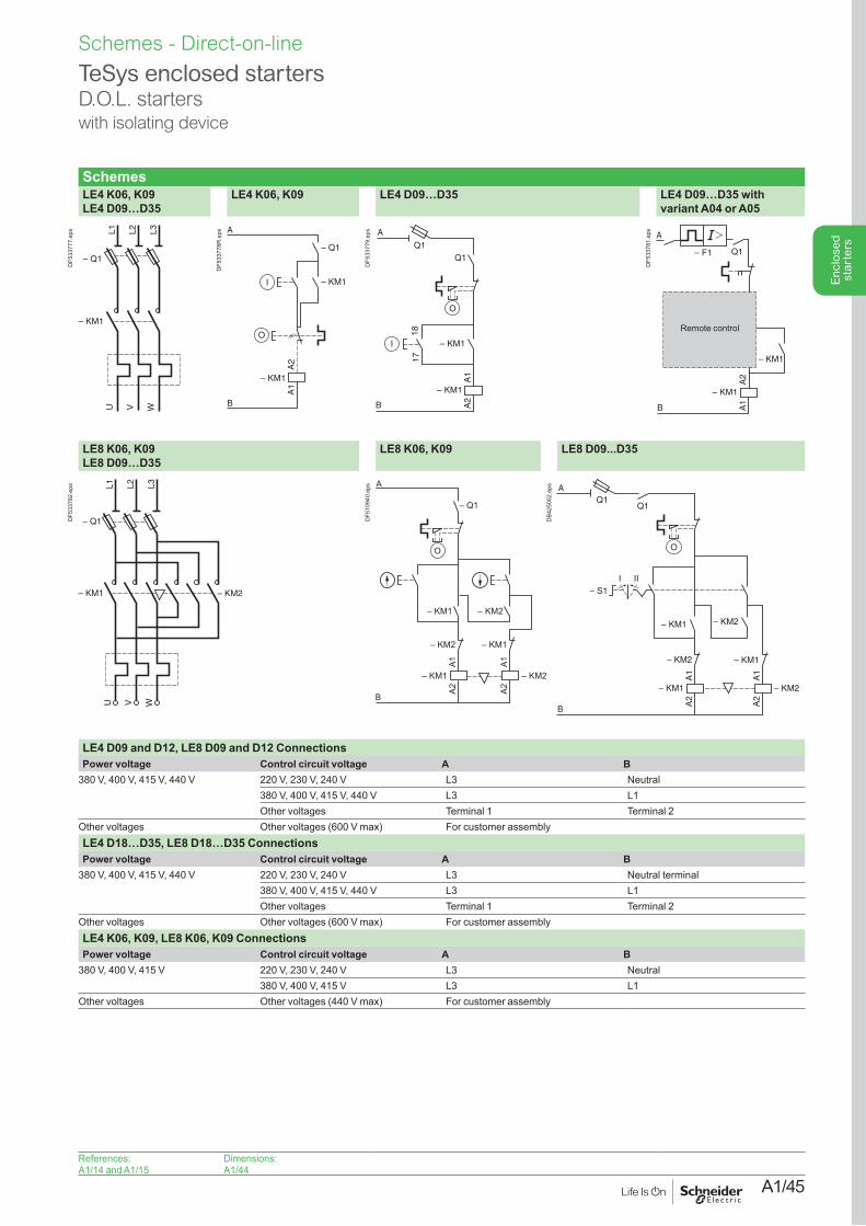
A1/45
Enc
lose
d st
arte
rs
TeSys enclosed startersD.O.L. starterswith isolating device
SchemesLE4 K06, K09 LE4 D09…D35
LE4 K06, K09 LE4 D09…D35 LE4 D09…D35 with variant A04 or A05
– Q1
– KM1
L1 L2 L3
U WV
DF5
3377
7.ep
s
– KM1
– Q1
O
I
– KM1
A1
A2
A
B
DF5
3377
8R.e
ps
B
A
A1
A2
– KM1
– KM1
1817
Q1Q1
O
I
DF5
3377
9.ep
s
1314
2122
O
l– KM1
A2
A1
– KM1
Q1– F1
B
A
Remote control
DF5
3378
1.ep
s
LE8 K06, K09 LE8 D09…D35
LE8 K06, K09 LE8 D09...D35
– Q1
– KM1 – KM2
L1 L2 L3
U V W
DF5
3378
2.ep
s
– KM2– KM1
– KM2
– KM2 – KM1
A1A2
– Q1
– KM1
A1A2
A
B
O
DF5
1094
0.ep
s
A1
A2
– KM1
– KM2
– KM2
A1
A2
– KM2
– KM1
– KM1
Q1Q1
A
B
– S1III
OD
B425
052.
eps
LE4 D09 and D12, LE8 D09 and D12 ConnectionsPower voltage Control circuit voltage A B
380 V, 400 V, 415 V, 440 V 220 V, 230 V, 240 V L3 Neutral380 V, 400 V, 415 V, 440 V L3 L1Other voltages Terminal 1 Terminal 2
Other voltages Other voltages (600 V max) For customer assemblyLE4 D18…D35, LE8 D18…D35 ConnectionsPower voltage Control circuit voltage A B
380 V, 400 V, 415 V, 440 V 220 V, 230 V, 240 V L3 Neutral terminal380 V, 400 V, 415 V, 440 V L3 L1Other voltages Terminal 1 Terminal 2
Other voltages Other voltages (600 V max) For customer assemblyLE4 K06, K09, LE8 K06, K09 ConnectionsPower voltage Control circuit voltage A B
380 V, 400 V, 415 V 220 V, 230 V, 240 V L3 Neutral380 V, 400 V, 415 V L3 L1
Other voltages Other voltages (440 V max) For customer assembly
References:A1/14 and A1/15
Dimensions:A1/44
Schemes - Direct-on-line
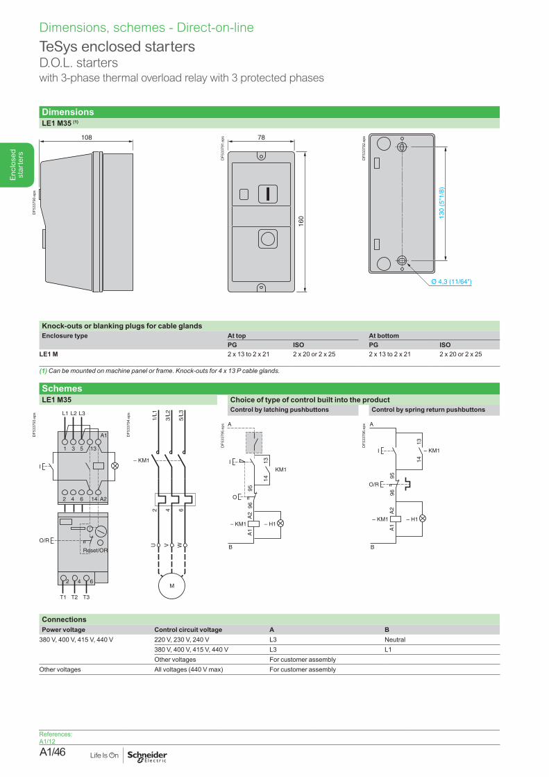
A1/46
Enc
lose
d st
arte
rs
TeSys enclosed startersD.O.L. starterswith 3-phase thermal overload relay with 3 protected phases
DimensionsLE1 M35 (1)
108
DF5
3379
0.ep
s
78
160
DF5
3379
1.ep
s
130
(5"1
/8)
DF5
3379
2.ep
s
Knock-outs or blanking plugs for cable glandsEnclosure type At top At bottom
PG ISO PG ISOLE1 M 2 x 13 to 2 x 21 2 x 20 or 2 x 25 2 x 13 to 2 x 21 2 x 20 or 2 x 25
(1)Canbemountedonmachinepanelorframe.Knock-outsfor4x13Pcableglands.
SchemesLE1 M35 Choice of type of control built into the product
I
O/R
1
2
3
4
5
6
13
14
A1
A2
2 4 6
L1 L2 L3
Reset/OR
T1 T2 T3
DF5
3379
3.ep
s
U WV
2 4 6
1/L1
3/L2
5/L3
M
– KM1
DF5
3379
4.ep
s
Control by latching pushbuttons Control by spring return pushbuttons
I
A
B
O
9596
– KM1 – H1
A2
A1
1413
KM1
DF5
3379
5.ep
s
I
A
B
1413
O/R
9596
– KM1 – H1
A2
A1
– KM1
DF5
3379
6.ep
s
ConnectionsPower voltage Control circuit voltage A B
380 V, 400 V, 415 V, 440 V 220 V, 230 V, 240 V L3 Neutral380 V, 400 V, 415 V, 440 V L3 L1Other voltages For customer assembly
Other voltages All voltages (440 V max) For customer assembly
References: A1/12
Dimensions, schemes - Direct-on-line
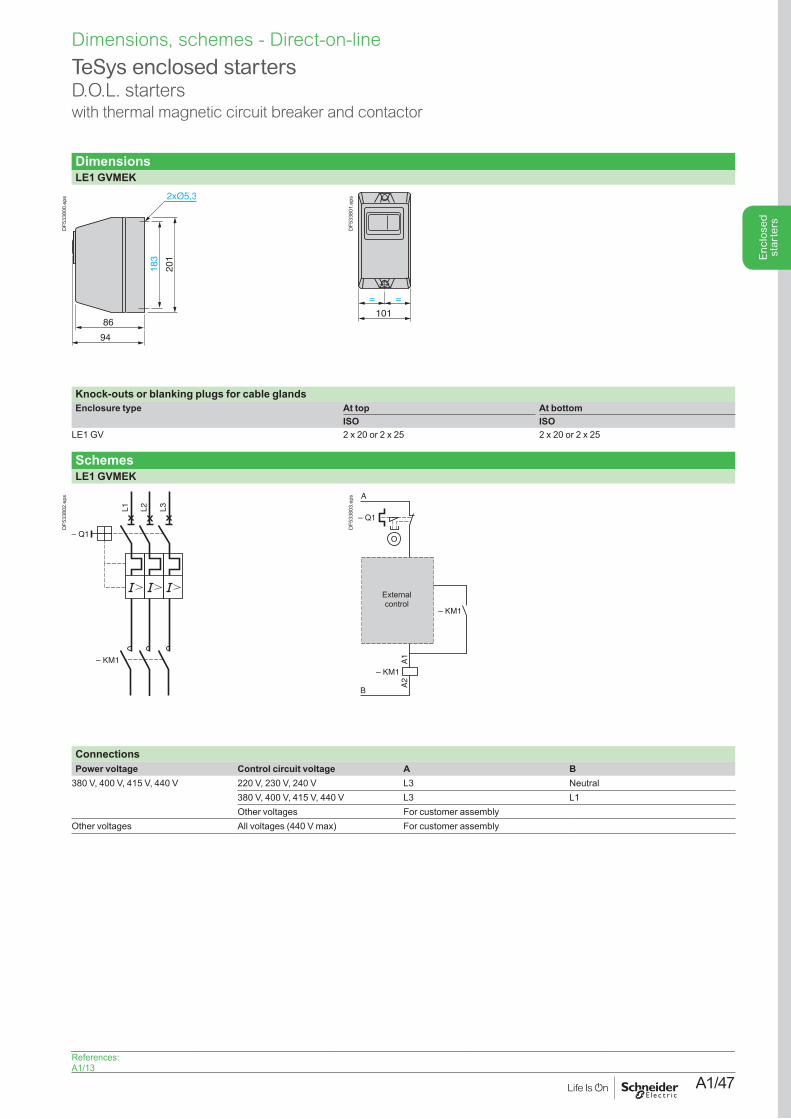
A1/47
Enc
lose
d st
arte
rs
TeSys enclosed startersD.O.L. starters with thermal magnetic circuit breaker and contactor
DimensionsLE1 GVMEK
86
94
183
201
DF5
3380
0.ep
s
= =
101
DF5
3380
1.ep
s
Knock-outs or blanking plugs for cable glandsEnclosure type At top At bottom
ISO ISOLE1 GV 2 x 20 or 2 x 25 2 x 20 or 2 x 25
SchemesLE1 GVMEK
L1 L2 L3
– KM1
– Q1
DF5
3380
2.ep
s
A1
A2
O
I – KM1
– KM1
– Q1
A
B
External control
DF5
3380
3.ep
s
ConnectionsPower voltage Control circuit voltage A B
380 V, 400 V, 415 V, 440 V 220 V, 230 V, 240 V L3 Neutral380 V, 400 V, 415 V, 440 V L3 L1Other voltages For customer assembly
Other voltages All voltages (440 V max) For customer assembly
References: A1/13
Dimensions, schemes - Direct-on-line
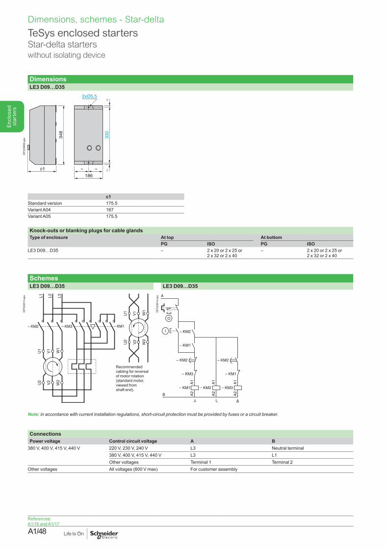
A1/48
Enc
lose
d st
arte
rsDimensions, schemes - Star-delta
DimensionsLE3 D09…D35
c1
348
330
==
=
186
=
DF5
3380
8.ep
s
c1Standard version 175.5Variant A04 167Variant A05 175.5
Knock-outs or blanking plugs for cable glandsType of enclosure At top At bottom
PG ISO PG ISOLE3 D09…D35 – 2 x 20 or 2 x 25 or
2 x 32 or 2 x 40– 2 x 20 or 2 x 25 or
2 x 32 or 2 x 40
SchemesLE3 D09…D35 LE3 D09…D35
– KM2 – KM3 – KM1
U1
V1
W1
U2
V2
W2
L1 L2 L3
U1
V1
W1
U2
V2
W2
Recommended cabling for reversal of motor rotation (standard motor, viewed from shaft end).
DF5
3381
3.ep
s
A1
A2
– KM1
– KM3
– KM2
– KM1
– KM2
A1
A2
– KM3
– KM1
A1
A2
– KM2
– KM2
B
A
O
I
Y
L
DF5
3381
4.ep
s
Note: inaccordancewithcurrentinstallationregulations,short-circuitprotectionmustbeprovidedbyfusesoracircuitbreaker.
ConnectionsPower voltage Control circuit voltage A B
380 V, 400 V, 415 V, 440 V 220 V, 230 V, 240 V L3 Neutral terminal380 V, 400 V, 415 V, 440 V L3 L1Other voltages Terminal 1 Terminal 2
Other voltages All voltages (600 V max) For customer assembly
TeSys enclosed startersStar-delta starterswithout isolating device
References: A1/16 and A1/17
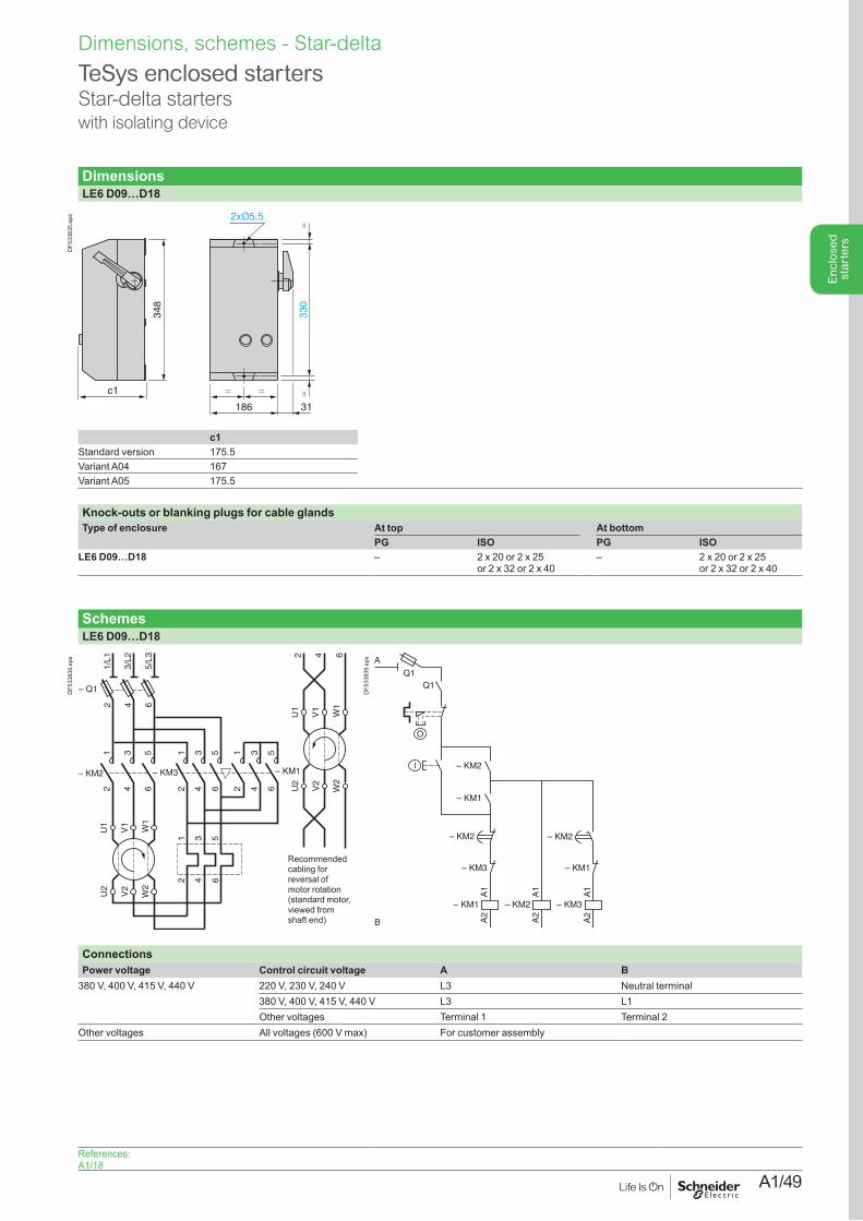
A1/49
Enc
lose
d st
arte
rs
Dimensions, schemes - Star-delta
DimensionsLE6 D09…D18
c1
348
330
==
=
186 31
=
DF5
3383
5.ep
s
c1Standard version 175.5Variant A04 167Variant A05 175.5
Knock-outs or blanking plugs for cable glandsType of enclosure At top At bottom
PG ISO PG ISOLE6 D09…D18 – 2 x 20 or 2 x 25
or 2 x 32 or 2 x 40– 2 x 20 or 2 x 25
or 2 x 32 or 2 x 40
SchemesLE6 D09…D18
– KM2
12
34
56
– KM3
12
34
56
– KM1
12
34
56
U1
V1
W1
U2
V2
W2
1 3 5
2 4 6
– Q1
1/L1
2
3/L2
4
5/L3
6
U1
V1
W1
U2
V2
W2
2 4 6
Recommended cabling for reversal of motor rotation (standard motor, viewed from shaft end)
DF5
3383
8.ep
s
A1
A2
– KM1
– KM3
– KM2
– KM1
l
– KM2
A1
A2
– KM3
– KM1
A1
A2
– KM2
– KM2
B
O
A
Q1Q1
DF5
3383
9.ep
s
ConnectionsPower voltage Control circuit voltage A B
380 V, 400 V, 415 V, 440 V 220 V, 230 V, 240 V L3 Neutral terminal380 V, 400 V, 415 V, 440 V L3 L1Other voltages Terminal 1 Terminal 2
Other voltages All voltages (600 V max) For customer assembly
TeSys enclosed startersStar-delta starterswith isolating device
References: A1/18
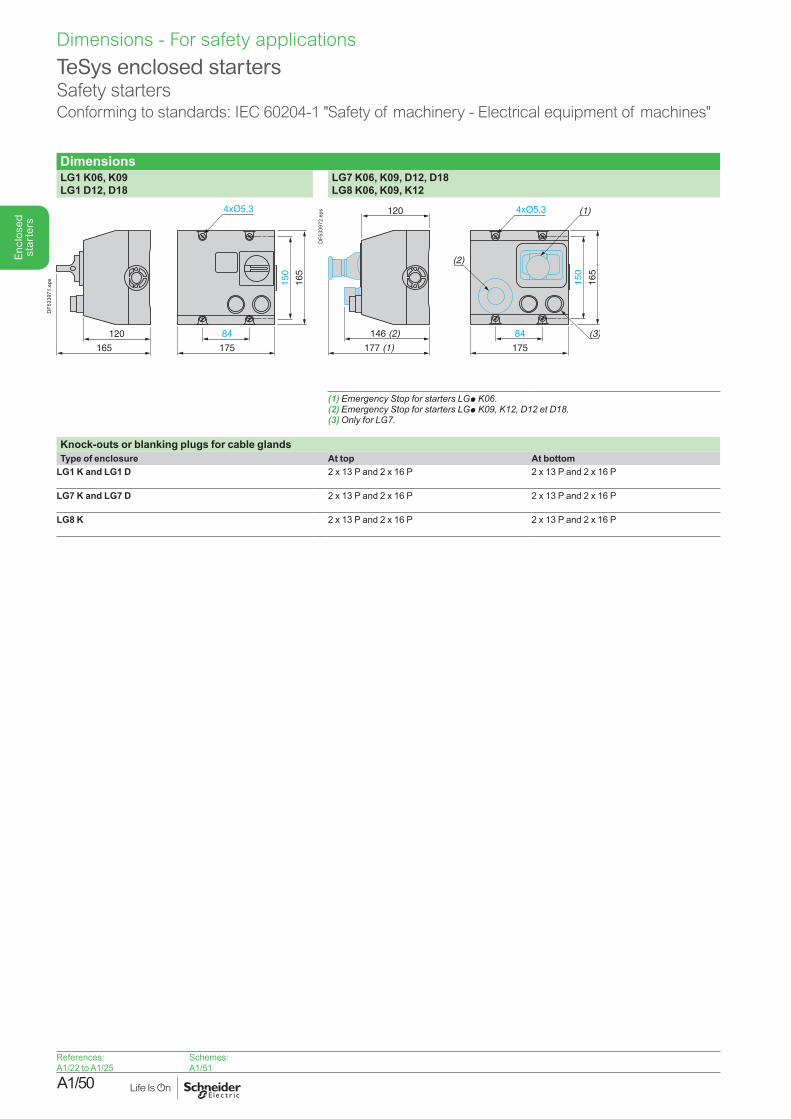
A1/50
Enc
lose
d st
arte
rsDimensions - For safety applications
TeSys enclosed startersSafety startersConforming to standards: IEC 60204-1 "Safety of machinery - Electrical equipment of machines"
DimensionsLG1 K06, K09 LG1 D12, D18
LG7 K06, K09, D12, D18 LG8 K06, K09, K12
120
165
84
175
150
165
DF5
3397
1.ep
s
146 (2)
120
177 (1)
84
175
150
165
(1)
(2)
(3)
DF5
3397
2.ep
s
(1) Emergency Stop for starters LGpK06.(2) Emergency Stop for starters LGpK09,K12,D12etD18.(3)OnlyforLG7.
Knock-outs or blanking plugs for cable glandsType of enclosure At top At bottom
LG1 K and LG1 D 2 x 13 P and 2 x 16 P 2 x 13 P and 2 x 16 P
LG7 K and LG7 D 2 x 13 P and 2 x 16 P 2 x 13 P and 2 x 16 P
LG8 K 2 x 13 P and 2 x 16 P 2 x 13 P and 2 x 16 P
References:A1/22 to A1/25
Schemes:A1/51
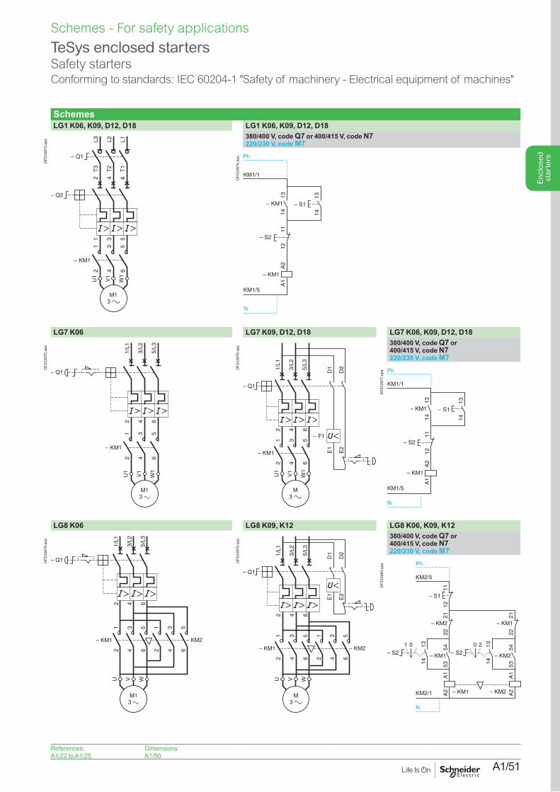
A1/51
Enc
lose
d st
arte
rs
Schemes - For safety applications
TeSys enclosed startersSafety startersConforming to standards: IEC 60204-1 "Safety of machinery - Electrical equipment of machines"
SchemesLG1 K06, K09, D12, D18 LG1 K06, K09, D12, D18
L3T
3
L2T
2
L1T
1
– Q1
1 3 5
2
– Q2
4 6
– KM1
12
34
56
U1
W1
V1
DF5
3397
3.ep
s 380/400 V, code Q7 or 400/415 V, code N7220/230 V, code M7
KM1/1
KM1/5
– KM1
– KM1
– S2
1314
1314
1112
A2
A1
– S1
Ph
N
DF5
3397
4.ep
s
LG7 K06 LG7 K09, D12, D18 LG7 K06, K09, D12, D18
2 4 6
1/L1
3/L2
5/L3
– KM1
12
34
56
U1
W1
V1
– Q1
DF5
3397
5.ep
s
1/L1
– Q1
3/L2
5/L3
– F1
U1
W1
V1
– KM1
1 3 5
2 4 6
2 4 6
D1
D2
E1
E2
DF5
3397
6.ep
s 380/400 V, code Q7 or 400/415 V, code N7220/230 V, code M7
KM1/1
KM1/5
– KM1
– KM1
– S2
1314
1314
1112
A2
A1
– S1
Ph
N
DF5
3397
7.ep
s
LG8 K06 LG8 K09, K12 LG8 K06, K09, K12
1/L1
– Q1
3/L2
5/L3
U WV
– KM1 – KM2
1 3 5 1 3 5
2 4 6 2 4 6
2 4 6
DF5
3397
8.ep
s
1/L1
– Q1
3/L2
5/L3
U WV
– KM1 – KM2
1 3 5 1 3 5
2 4 6 2 4 6
2 4 6
D1
D2
E1
E2
DF5
3397
9.ep
s 380/400 V, code Q7 or 400/415 V, code N7220/230 V, code M7
11
KM2/5
KM2/1
– KM1
– KM2– KM1
12
1314
5453
– KM2
2122
A1
A2
A1
A2
– S1
– S21 0
– KM2
1314
5453
– KM1
2122
– S220
Ph
N
DF5
3398
0.ep
s
References:A1/22 to A1/25
Dimensions:A1/50
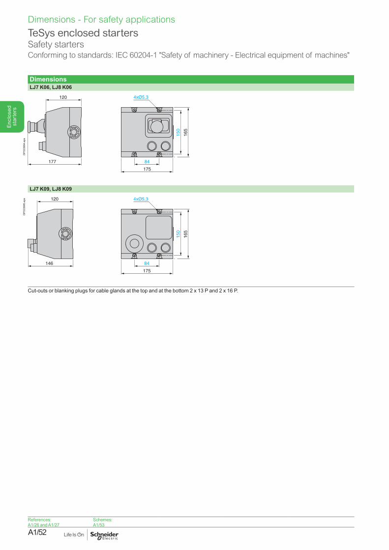
A1/52
Enc
lose
d st
arte
rsDimensions - For safety applications
TeSys enclosed starters Safety startersConforming to standards: IEC 60204-1 "Safety of machinery - Electrical equipment of machines"
DimensionsLJ7 K06, LJ8 K06
177
120
84
175
150
165
DF5
3399
4.ep
s
LJ7 K09, LJ8 K09
146
120
84
175
150
165
DF5
3399
5.ep
s
Cut-outs or blanking plugs for cable glands at the top and at the bottom 2 x 13 P and 2 x 16 P.
References:A1/26 and A1/27
Schemes:A1/53
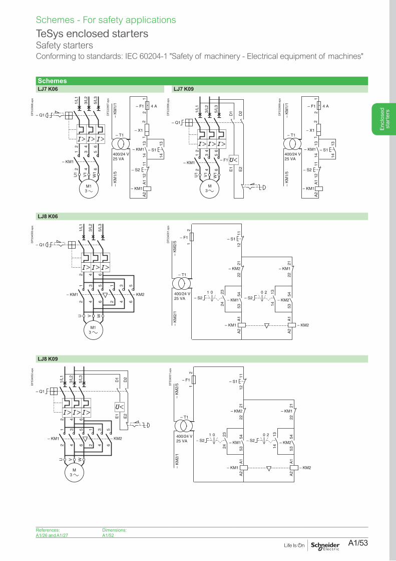
A1/53
Enc
lose
d st
arte
rs
Schemes - For safety applications
TeSys enclosed starters Safety startersConforming to standards: IEC 60204-1 "Safety of machinery - Electrical equipment of machines"
SchemesLJ7 K06 LJ7 K09
2 4 6
1/L1
3/L2
5/L3
– KM1
12
34
56
U1
W1
V1
– Q1DF5
3399
6.ep
s
– K
M1/
5–
KM
1/1
– KM1
– X1
– KM1
– S2
– F1 4 A
1314
1314
1112
A1
A2
– S1
– T1
400/24 V25 VA
12
21
DF5
3399
7.ep
s
1/L1
– Q1
3/L2
5/L3
– F1
U1
W1
V1
M3
– KM1
1 3 5
2 4 6
2 4 6
D1
D2
E1
E2
DF5
3399
8.ep
s
– K
M1/
5–
KM
1/1
– KM1
– X1
– KM1
– S2
– F1 4 A
1314
1314
1112
A1
A2
– S1
– T1
400/24 V25 VA
12
21
DF5
3399
9.ep
s
LJ8 K06
1/L1
– Q1
3/L2
5/L3
U WV
– KM1 – KM2
1 3 5 1 3 5
2 4 6 2 4 6
2 4 6
DF5
3400
0.ep
s
11
– KM1
– KM2– KM1
12
2324
5453
– KM2
2122
A1
A2
A1
A2
– S1
– S21 0
– KM2
1314
5453
– KM1
2122
– S220
– K
M2/
1–
KM
2/5
– T1
400/24 V25 VA
– F1
21D
F534
001.
eps
LJ8 K09
1/L1
– Q1
3/L2
5/L3
U WV
– KM1 – KM2
1 3 5 1 3 5
2 4 6 2 4 6
2 4 6
D1
D2
E1
E2
DF5
3400
2.ep
s
11
– KM1
– KM2– KM1
12
2324
5453
– KM2
2122
A1
A2
A1
A2
– S1
– S21 0
– KM2
1314
5453
– KM1
2122
– S220
– K
M2/
1–
KM
2/5
– T1
400/24 V25 VA
– F1
21D
F534
001.
eps
References:A1/26 and A1/27
Dimensions:A1/52
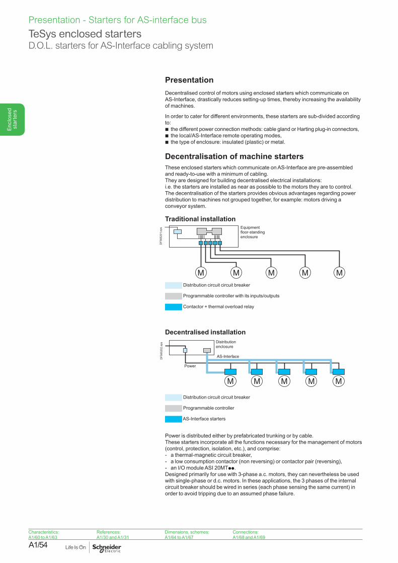
A1/54
Enc
lose
d st
arte
rs
Characteristics:A1/60 to A1/63
References:A1/30 and A1/31
Dimensions, schemes:A1/64 to A1/67
Connections:A1/68 and A1/69
Presentation Decentralised control of motors using enclosed starters which communicate on AS-Interface, drastically reduces setting-up times, thereby increasing the availability of machines.
In order to cater for different environments, these starters are sub-divided according to:b the different power connection methods: cable gland or Harting plug-in connectors,b the local/AS-Interface remote operating modes,b the type of enclosure: insulated (plastic) or metal.
Decentralisation of machine starters These enclosed starters which communicate on AS-Interface are pre-assembled and ready-to-use with a minimum of cabling. They are designed for building decentralised electrical installations: i.e. the starters are installed as near as possible to the motors they are to control. The decentralisation of the starters provides obvious advantages regarding power distribution to machines not grouped together, for example: motors driving a conveyor system.
Traditional installationEquipmentfloor-standingenclosure
DF5
6520
1.ep
s
Distribution circuit circuit breaker
Programmable controller with its inputs/outputs
Contactor + thermal overload relay
Decentralised installation
M M M M M
AS-Interface
Distribution enclosure
Power
DF5
6520
2.ep
s
Distribution circuit circuit breaker
Programmable controller
AS-Interface starters
Power is distributed either by prefabricated trunking or by cable. These starters incorporate all the functions necessary for the management of motors (control, protection, isolation, etc.), and comprise:- a thermal-magnetic circuit breaker,- a low consumption contactor (non reversing) or contactor pair (reversing),- an I/O module ASI 20MTpp.Designed primarily for use with 3-phase a.c. motors, they can nevertheless be used with single-phase or d.c. motors. In these applications, the 3 phases of the internal circuit breaker should be wired in series (each phase sensing the same current) in order to avoid tripping due to an assumed phase failure.
TeSys enclosed startersD.O.L. starters for AS-Interface cabling system
Presentation - Starters for AS-interface bus
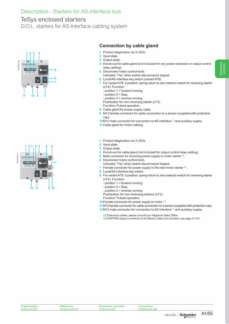
A1/55
Enc
lose
d st
arte
rs
Connection by cable gland 1 Product diagnostics via 3 LEDs.2 Input state.3 Output state.4 Knock-out for cable gland (not included for any power extension or output control
relay cabling).5 Disconnect rotary control knob.
Indicates “Trip” when switch-disconnector tripped.6 Local/AS-Interface key switch (variant A79).7 For variant A79: 3-position, spring return to zero selector switch for reversing starter
(LF4). Function: - position 1 = forward running, - position 0 = Stop,
- position 2 = reverse running. Pushbutton for non-reversing starter (LF3). Function: Pulsed operation.
8 Cable gland for power supply cable.9 M12 female connector for cable connection to a sensor (supplied with protective
cap). 10 M12 male connector for connection to AS-Interface (1) and auxiliary supply.11 Cable gland for motor cabling.
Connection by plug-in connectors(variant A74) 1 Product diagnostics via 3 LEDs.2 Input state.3 Output state.4 Knock-out for cable gland (not included for output control relay cabling).5 Male connector for incoming power supply to motor starter (2).6 Disconnect rotary control knob.
Indicates “Trip” when switch-disconnector tripped.7 Female connector for power supply to the next motor starter (2).8 Local/AS-Interface key switch.9 For variant A79: 3-position, spring return to zero selector switch for reversing starter
(LF4). Function: - position 1 = forward running,- position 0 = Stop,
- position 2 = reverse running. Pushbutton: for non-reversing starters (LF3). Function: Pulsed operation.
10 Female connector for power supply to motor (2).11 M12 female connector for cable connection to a sensor (supplied with protective cap). 12 M12 male connector for connection to AS-Interface (1) and auxiliary supply.
(1)Extensioncables:pleaseconsultyourRegionalSalesOffice.(2)HARTINGplug-inconnectortobefittedtocable(notincluded,seepageA1-51).
Characteristics:A1/60 to A1/63
References:A1/30 and A1/31
Dimensions, schemes:A1/64 to A1/67
Connections:A1/68 and A1/69
TeSys enclosed startersD.O.L. starters for AS-Interface cabling system
5
1 2 3 4
67
11 10 9 8
DF5
2636
2.ep
s
1 2 3 4
101112
8 6 5
7
9
DF5
2636
4.ep
s
Description - Starters for AS-interface bus
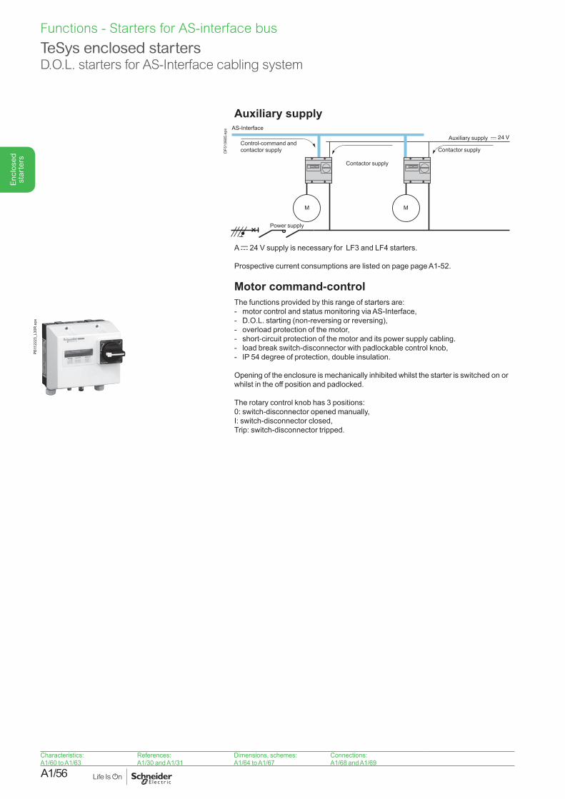
A1/56
Enc
lose
d st
arte
rs
Characteristics:A1/60 to A1/63
References:A1/30 and A1/31
Dimensions, schemes:A1/64 to A1/67
Connections:A1/68 and A1/69
Auxiliary supply
Control-command and contactor supply
Power supply
AS-Interface
Contactor supply
Auxiliary supply
Contactor supply
DF5
1068
5.ep
s
A c 24 V supply is necessary for LF3 and LF4 starters.
Prospective current consumptions are listed on page page A1-52.
Motor command-control The functions provided by this range of starters are:- motor control and status monitoring via AS-Interface,- D.O.L. starting (non-reversing or reversing),- overload protection of the motor,- short-circuit protection of the motor and its power supply cabling.- load break switch-disconnector with padlockable control knob,- IP 54 degree of protection, double insulation.
Opening of the enclosure is mechanically inhibited whilst the starter is switched on or whilst in the off position and padlocked.
The rotary control knob has 3 positions:0: switch-disconnector opened manually,I: switch-disconnector closed,Trip: switch-disconnector tripped.
TeSys enclosed startersD.O.L. starters for AS-Interface cabling system
PB11
2223
_L30
R.e
psFunctions - Starters for AS-interface bus
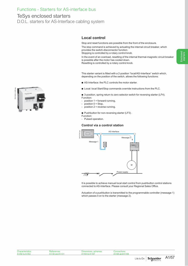
A1/57
Enc
lose
d st
arte
rs
Local control Stop and reset functions are possible from the front of the enclosure. The stop command is achieved by actuating the internal circuit breaker, which provides the switch-disconnector function. Stopping is controlled by a rotary control knob.In the event of an overload, resetting of the internal thermal-magnetic circuit breaker is possible after the motor has cooled down.Resetting is controlled by a rotary control knob.
Integral local/AS-Interface control (variant A79) This starter variant is fitted with a 2-position “local/AS-Interface” switch which, depending on the position of the switch, allows the following functions:
b AS-Interface: the PLC controls the motor starter.
b Local: local Start/Stop commands override instructions from the PLC.
b 3-position, spring return to zero selector switch for reversing starter (LF4).Function: - position 1 = forward running,- position 0 = Stop,- position 2 = reverse running.
b Pushbutton for non-reversing starter (LF3) . Function: - Pulsed operation.
Control via a control station
AS-Interface
Message 1
Message 2
Power supply
DF5
1074
2.ep
s
It is possible to achieve manual local start control from pushbutton control stations connected to AS-Interface. Please consult your Regional Sales Office.
Actuation of a pushbutton is transmitted to the programmable controller (message 1) which passes it on to the starter (message 2).
Characteristics:A1/60 to A1/63
References:A1/30 and A1/31
Dimensions, schemes:A1/64 to A1/67
Connections:A1/68 and A1/69
TeSys enclosed startersD.O.L. starters for AS-Interface cabling system
PB11
2232
_L32
R.e
ps
Functions - Starters for AS-interface bus
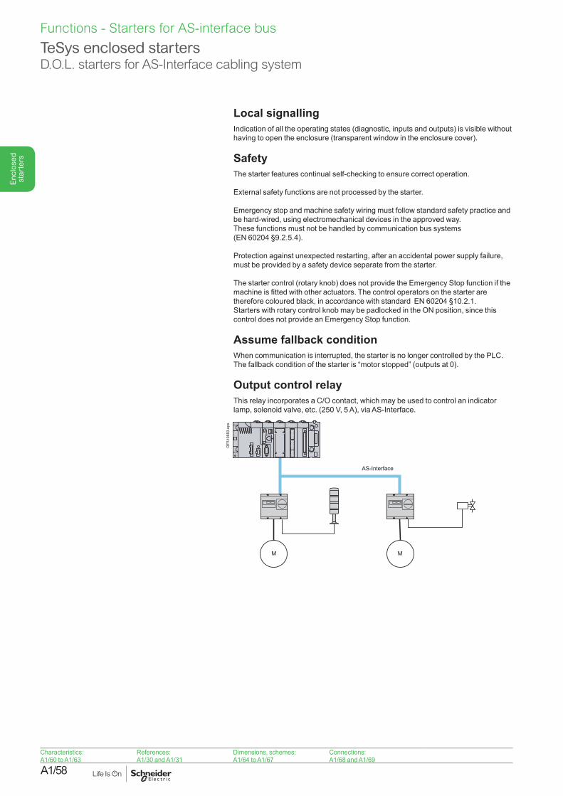
A1/58
Enc
lose
d st
arte
rs
Characteristics:A1/60 to A1/63
References:A1/30 and A1/31
Dimensions, schemes:A1/64 to A1/67
Connections:A1/68 and A1/69
TeSys enclosed startersD.O.L. starters for AS-Interface cabling system
Local signallingIndication of all the operating states (diagnostic, inputs and outputs) is visible without having to open the enclosure (transparent window in the enclosure cover).
SafetyThe starter features continual self-checking to ensure correct operation.
External safety functions are not processed by the starter.
Emergency stop and machine safety wiring must follow standard safety practice and be hard-wired, using electromechanical devices in the approved way. These functions must not be handled by communication bus systems (EN 60204 §9.2.5.4).
Protection against unexpected restarting, after an accidental power supply failure, must be provided by a safety device separate from the starter.
The starter control (rotary knob) does not provide the Emergency Stop function if the machine is fitted with other actuators. The control operators on the starter are therefore coloured black, in accordance with standard EN 60204 §10.2.1. Starters with rotary control knob may be padlocked in the ON position, since this control does not provide an Emergency Stop function.
Assume fallback conditionWhen communication is interrupted, the starter is no longer controlled by the PLC. The fallback condition of the starter is “motor stopped” (outputs at 0).
Output control relayThis relay incorporates a C/O contact, which may be used to control an indicator lamp, solenoid valve, etc. (250 V, 5 A), via AS-Interface.
AS-Interface
DF5
1068
3.ep
s
Functions - Starters for AS-interface bus
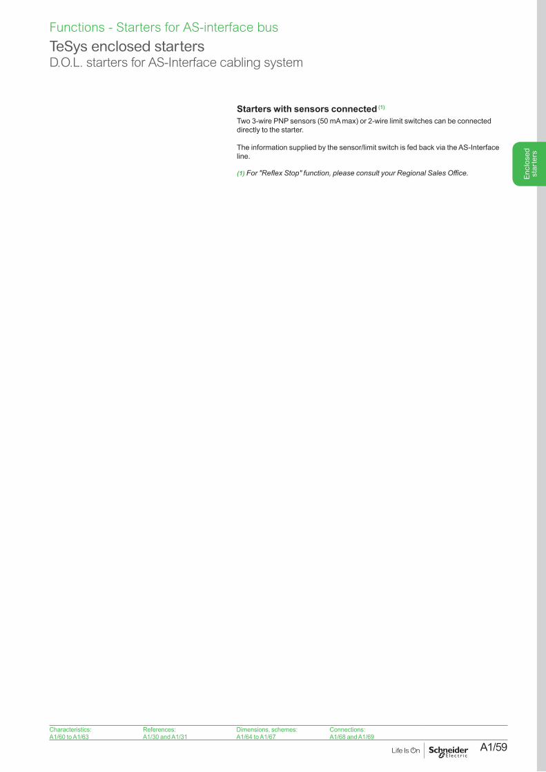
A1/59
Enc
lose
d st
arte
rs
Characteristics:A1/60 to A1/63
References:A1/30 and A1/31
Dimensions, schemes:A1/64 to A1/67
Connections:A1/68 and A1/69
Starters with sensors connected (1)
Two 3-wire PNP sensors (50 mA max) or 2-wire limit switches can be connected directly to the starter.
The information supplied by the sensor/limit switch is fed back via the AS-Interface line.
(1)For"ReflexStop"function,pleaseconsultyourRegionalSalesOffice.
TeSys enclosed startersD.O.L. starters for AS-Interface cabling system
Functions - Starters for AS-interface bus
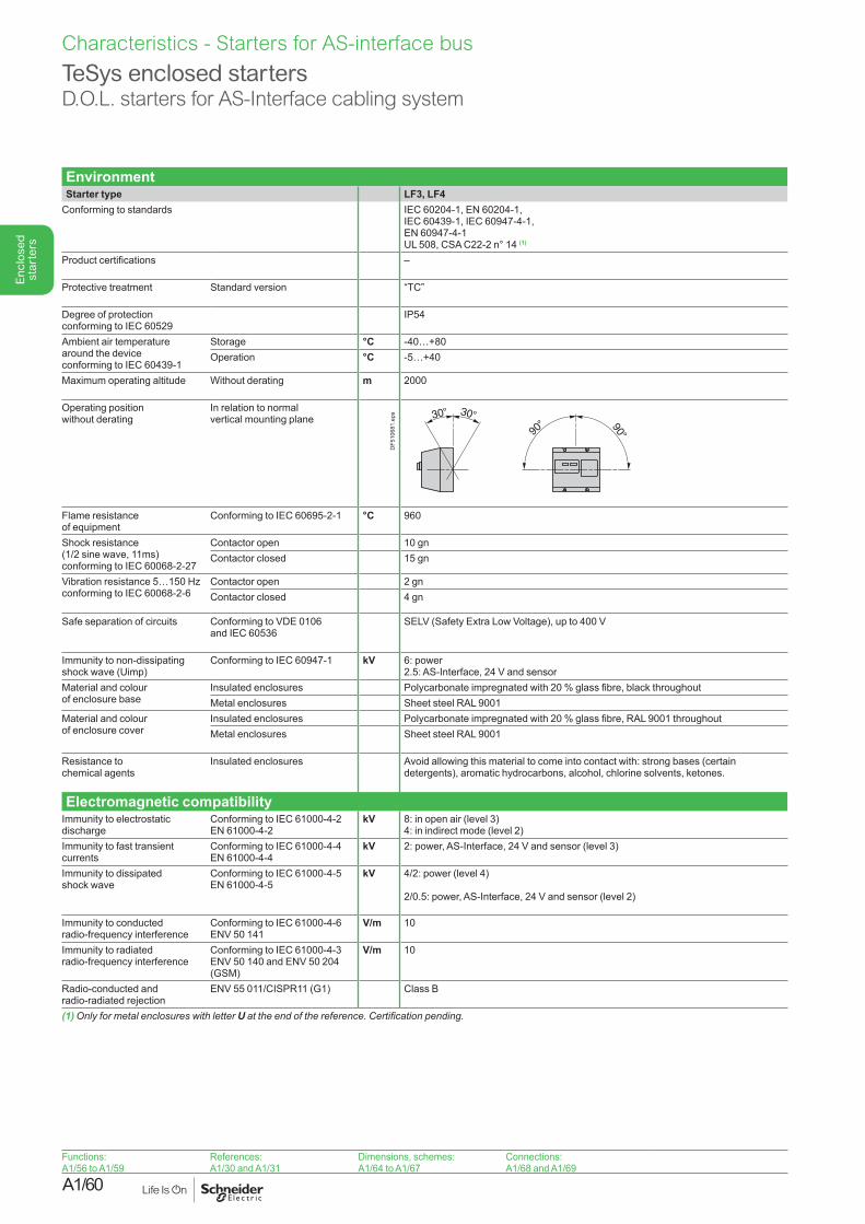
A1/60
Enc
lose
d st
arte
rs
Functions:A1/56 to A1/59
References:A1/30 and A1/31
Dimensions, schemes:A1/64 to A1/67
Connections:A1/68 and A1/69
Environment Starter type LF3, LF4
Conforming to standards IEC 60204-1, EN 60204-1,IEC 60439-1, IEC 60947-4-1, EN 60947-4-1UL 508, CSA C22-2 n° 14 (1)
Product certifications –
Protective treatment Standard version “TC”
Degree of protectionconforming to IEC 60529
IP54
Ambient air temperature around the device conforming to IEC 60439-1
Storage °C -40…+80 Operation °C -5…+40
Maximum operating altitude Without derating m 2000
Operating position without derating
In relation to normal vertical mounting plane
DF5
1068
1.ep
s
Flame resistance of equipment
Conforming to IEC 60695-2-1 °C 960
Shock resistance (1/2 sine wave, 11ms) conforming to IEC 60068-2-27
Contactor open 10 gnContactor closed 15 gn
Vibration resistance 5…150 Hz conforming to IEC 60068-2-6
Contactor open 2 gnContactor closed 4 gn
Safe separation of circuits Conforming to VDE 0106 and IEC 60536
SELV (Safety Extra Low Voltage), up to 400 V
Immunity to non-dissipating shock wave (Uimp)
Conforming to IEC 60947-1 kV 6: power2.5: AS-Interface, 24 V and sensor
Material and colour of enclosure base
Insulated enclosures Polycarbonate impregnated with 20 % glass fibre, black throughoutMetal enclosures Sheet steel RAL 9001
Material and colour of enclosure cover
Insulated enclosures Polycarbonate impregnated with 20 % glass fibre, RAL 9001 throughoutMetal enclosures Sheet steel RAL 9001
Resistance to chemical agents
Insulated enclosures Avoid allowing this material to come into contact with: strong bases (certain detergents), aromatic hydrocarbons, alcohol, chlorine solvents, ketones.
Electromagnetic compatibility Immunity to electrostatic discharge
Conforming to IEC 61000-4-2EN 61000-4-2
kV 8: in open air (level 3)4: in indirect mode (level 2)
Immunity to fast transient currents
Conforming to IEC 61000-4-4EN 61000-4-4
kV 2: power, AS-Interface, 24 V and sensor (level 3)
Immunity to dissipated shock wave
Conforming to IEC 61000-4-5EN 61000-4-5
kV 4/2: power (level 4)
2/0.5: power, AS-Interface, 24 V and sensor (level 2)
Immunity to conducted radio-frequency interference
Conforming to IEC 61000-4-6ENV 50 141
V/m 10
Immunity to radiated radio-frequency interference
Conforming to IEC 61000-4-3ENV 50 140 and ENV 50 204 (GSM)
V/m 10
Radio-conducted and radio-radiated rejection
ENV 55 011/CISPR11 (G1) Class B
(1) Only for metal enclosures with letter Uattheendofthereference.Certificationpending.
TeSys enclosed startersD.O.L. starters for AS-Interface cabling system
Characteristics - Starters for AS-interface bus
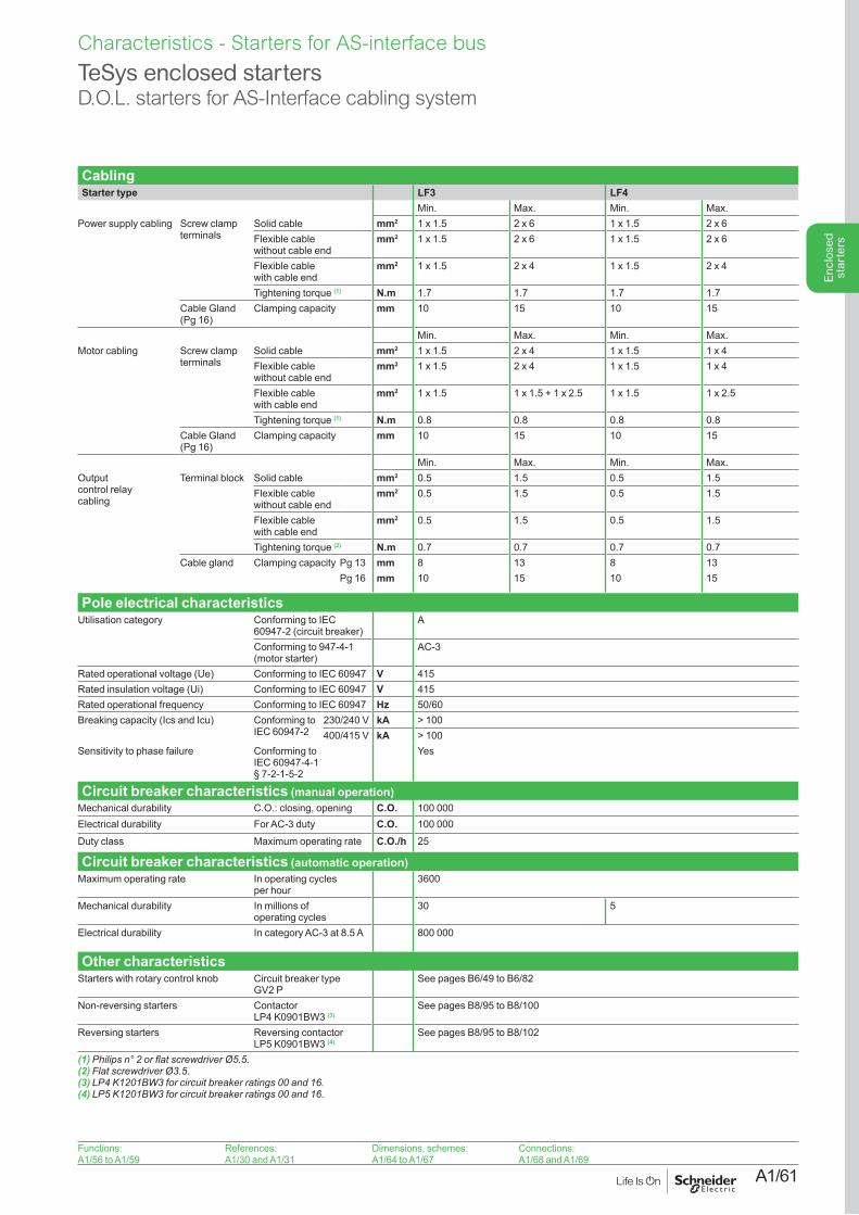
A1/61
Enc
lose
d st
arte
rs
Functions:A1/56 to A1/59
References:A1/30 and A1/31
Dimensions, schemes:A1/64 to A1/67
Connections:A1/68 and A1/69
CablingStarter type LF3 LF4
Min. Max. Min. Max.Power supply cabling Screw clamp
terminalsSolid cable mm2 1 x 1.5 2 x 6 1 x 1.5 2 x 6Flexible cable without cable end
mm2 1 x 1.5 2 x 6 1 x 1.5 2 x 6
Flexible cable with cable end
mm2 1 x 1.5 2 x 4 1 x 1.5 2 x 4
Tightening torque (1) N.m 1.7 1.7 1.7 1.7Cable Gland (Pg 16)
Clamping capacity mm 10 15 10 15
Min. Max. Min. Max.Motor cabling Screw clamp
terminalsSolid cable mm2 1 x 1.5 2 x 4 1 x 1.5 1 x 4Flexible cable without cable end
mm2 1 x 1.5 2 x 4 1 x 1.5 1 x 4
Flexible cable with cable end
mm2 1 x 1.5 1 x 1.5 + 1 x 2.5 1 x 1.5 1 x 2.5
Tightening torque (1) N.m 0.8 0.8 0.8 0.8Cable Gland (Pg 16)
Clamping capacity mm 10 15 10 15
Min. Max. Min. Max.Outputcontrol relaycabling
Terminal block Solid cable mm2 0.5 1.5 0.5 1.5Flexible cable without cable end
mm2 0.5 1.5 0.5 1.5
Flexible cable with cable end
mm2 0.5 1.5 0.5 1.5
Tightening torque (2) N.m 0.7 0.7 0.7 0.7Cable gland Clamping capacity Pg 13 mm 8 13 8 13
Pg 16 mm 10 15 10 15
Pole electrical characteristicsUtilisation category Conforming to IEC
60947-2 (circuit breaker)A
Conforming to 947-4-1 (motor starter)
AC-3
Rated operational voltage (Ue) Conforming to IEC 60947 V 415Rated insulation voltage (Ui) Conforming to IEC 60947 V 415Rated operational frequency Conforming to IEC 60947 Hz 50/60Breaking capacity (Ics and Icu) Conforming to
IEC 60947-2230/240 V kA > 100400/415 V kA > 100
Sensitivity to phase failure Conforming to IEC 60947-4-1 § 7-2-1-5-2
Yes
Circuit breaker characteristics (manual operation)Mechanical durability C.O.: closing, opening C.O. 100 000Electrical durability For AC-3 duty C.O. 100 000Duty class Maximum operating rate C.O./h 25
Circuit breaker characteristics (automatic operation)Maximum operating rate In operating cycles
per hour3600
Mechanical durability In millions of operating cycles
30 5
Electrical durability In category AC-3 at 8.5 A 800 000
Other characteristicsStarters with rotary control knob Circuit breaker type
GV2 PSee pages B6/49 to B6/82
Non-reversing starters Contactor LP4 K0901BW3 (3)
See pages B8/95 to B8/100
Reversing starters Reversing contactor LP5 K0901BW3 (4)
See pages B8/95 to B8/102
(1)Philipsn°2orflatscrewdriverØ5.5.(2)FlatscrewdriverØ3.5.(3)LP4K1201BW3forcircuitbreakerratings00and16.(4)LP5K1201BW3forcircuitbreakerratings00and16.
TeSys enclosed startersD.O.L. starters for AS-Interface cabling system
Characteristics - Starters for AS-interface bus
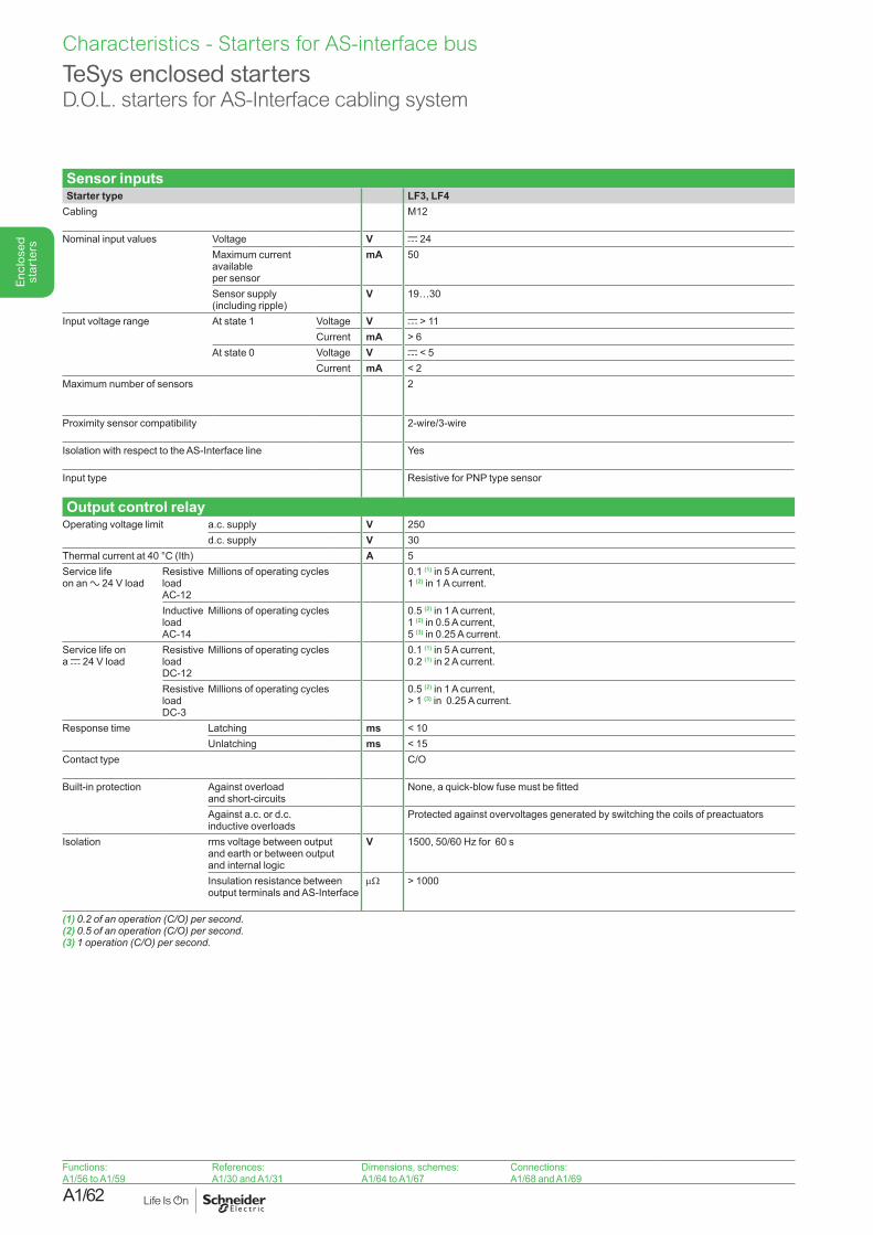
A1/62
Enc
lose
d st
arte
rs
Functions:A1/56 to A1/59
References:A1/30 and A1/31
Dimensions, schemes:A1/64 to A1/67
Connections:A1/68 and A1/69
Sensor inputsStarter type LF3, LF4
Cabling M12
Nominal input values Voltage V c 24Maximum current available per sensor
mA 50
Sensor supply (including ripple)
V 19…30
Input voltage range At state 1 Voltage V c > 11Current mA > 6
At state 0 Voltage V c < 5Current mA < 2
Maximum number of sensors 2
Proximity sensor compatibility 2-wire/3-wire
Isolation with respect to the AS-Interface line Yes
Input type Resistive for PNP type sensor
Output control relayOperating voltage limit a.c. supply V 250
d.c. supply V 30Thermal current at 40 °C (Ith) A 5Service life on an a 24 V load
Resistive load AC-12
Millions of operating cycles 0.1 (1) in 5 A current,1 (2) in 1 A current.
Inductive load AC-14
Millions of operating cycles 0.5 (2) in 1 A current,1 (2) in 0.5 A current,5 (3) in 0.25 A current.
Service life on a c 24 V load
Resistive load DC-12
Millions of operating cycles 0.1 (1) in 5 A current,0.2 (1) in 2 A current.
Resistive load DC-3
Millions of operating cycles 0.5 (2) in 1 A current,> 1 (3) in 0.25 A current.
Response time Latching ms < 10Unlatching ms < 15
Contact type C/O
Built-in protection Against overload and short-circuits
None, a quick-blow fuse must be fitted
Against a.c. or d.c. inductive overloads
Protected against overvoltages generated by switching the coils of preactuators
Isolation rms voltage between output and earth or between output and internal logic
V 1500, 50/60 Hz for 60 s
Insulation resistance between output terminals and AS-Interface
mW > 1000
(1)0.2ofanoperation(C/O)persecond.(2)0.5ofanoperation(C/O)persecond.(3)1operation(C/O)persecond.
TeSys enclosed startersD.O.L. starters for AS-Interface cabling system
Characteristics - Starters for AS-interface bus
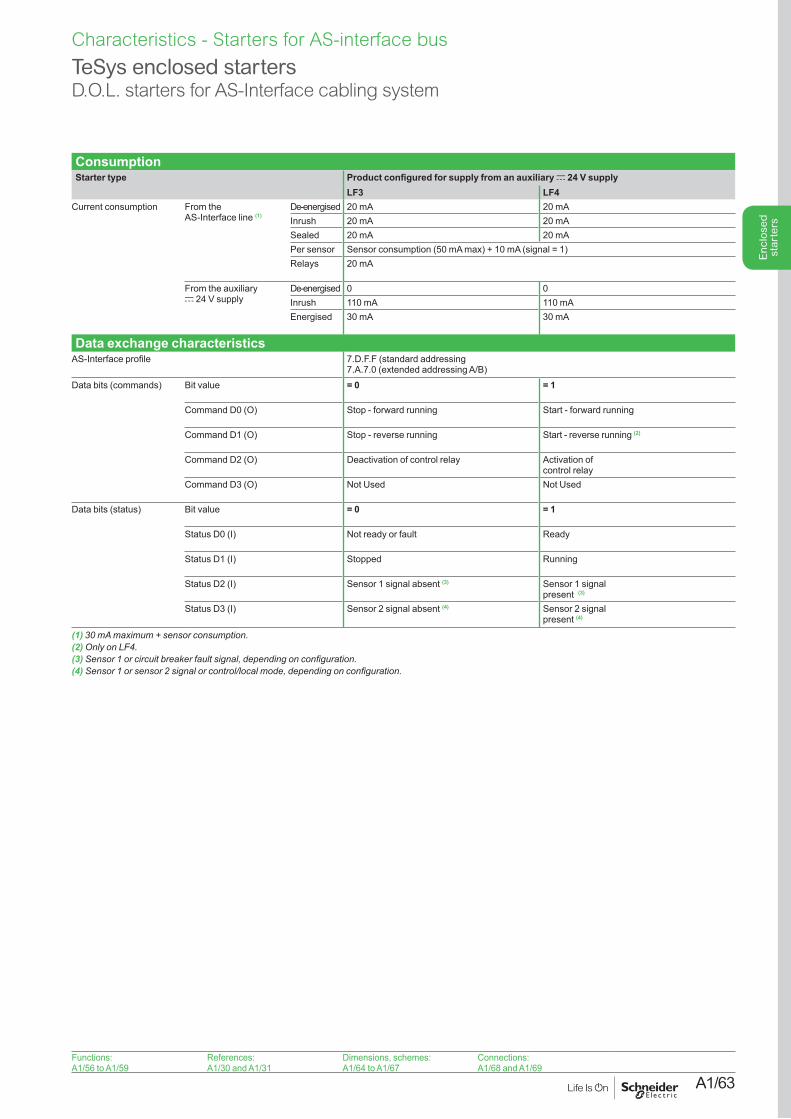
A1/63
Enc
lose
d st
arte
rs
Functions:A1/56 to A1/59
References:A1/30 and A1/31
Dimensions, schemes:A1/64 to A1/67
Connections:A1/68 and A1/69
ConsumptionStarter type Product configured for supply from an auxiliary c 24 V supply
LF3 LF4Current consumption From the
AS-Interface line (1)De-energised 20 mA 20 mAInrush 20 mA 20 mASealed 20 mA 20 mAPer sensor Sensor consumption (50 mA max) + 10 mA (signal = 1)Relays 20 mA
From the auxiliary c 24 V supply
De-energised 0 0Inrush 110 mA 110 mAEnergised 30 mA 30 mA
Data exchange characteristicsAS-Interface profile 7.D.F.F (standard addressing
7.A.7.0 (extended addressing A/B)Data bits (commands) Bit value = 0 = 1
Command D0 (O) Stop - forward running Start - forward running
Command D1 (O) Stop - reverse running Start - reverse running (2)
Command D2 (O) Deactivation of control relay Activation of control relay
Command D3 (O) Not Used Not Used
Data bits (status) Bit value = 0 = 1
Status D0 (I) Not ready or fault Ready
Status D1 (I) Stopped Running
Status D2 (I) Sensor 1 signal absent (3) Sensor 1 signal present (3)
Status D3 (I) Sensor 2 signal absent (4) Sensor 2 signal present (4)
(1)30mAmaximum+sensorconsumption.(2)OnlyonLF4.(3)Sensor1orcircuitbreakerfaultsignal,dependingonconfiguration.(4)Sensor1orsensor2signalorcontrol/localmode,dependingonconfiguration.
TeSys enclosed startersD.O.L. starters for AS-Interface cabling system
Characteristics - Starters for AS-interface bus
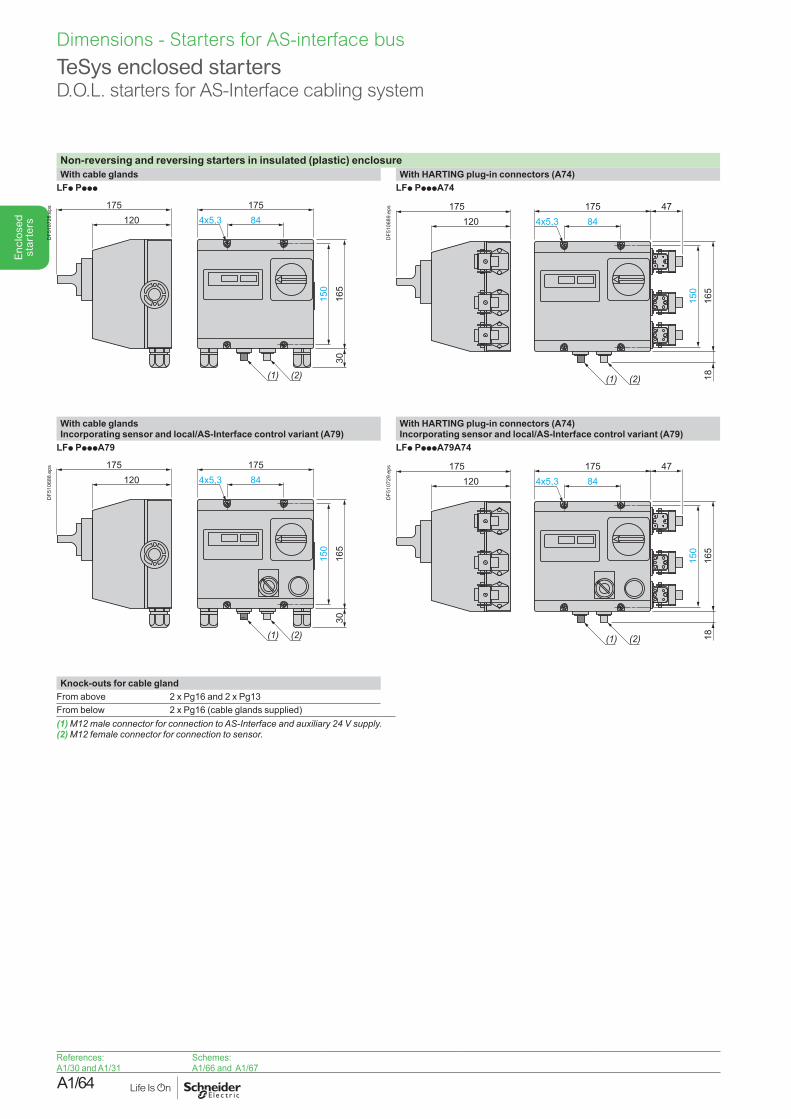
A1/64
Enc
lose
d st
arte
rs
References:A1/30 and A1/31
Schemes:A1/66 and A1/67
Non-reversing and reversing starters in insulated (plastic) enclosureWith cable glands With HARTING plug-in connectors (A74)
LFp Pppp LFp PpppA74
DF5
1072
8.ep
s
120
150
165
18
84
(1) (2)
4x5,3175175 47
DF5
1068
9.ep
s
With cable glandsIncorporating sensor and local/AS-Interface control variant (A79)
With HARTING plug-in connectors (A74)Incorporating sensor and local/AS-Interface control variant (A79)
LFp PpppA79 LFp PpppA79A74
DF5
1068
8.ep
s
120
150
165
18
84
(1) (2)
4x5,3175175 47
DF5
1072
9.ep
s
Knock-outs for cable glandFrom above 2 x Pg16 and 2 x Pg13From below 2 x Pg16 (cable glands supplied)(1)M12maleconnectorforconnectiontoAS-Interfaceandauxiliary24Vsupply.(2)M12femaleconnectorforconnectiontosensor.
TeSys enclosed startersD.O.L. starters for AS-Interface cabling system
Dimensions - Starters for AS-interface bus
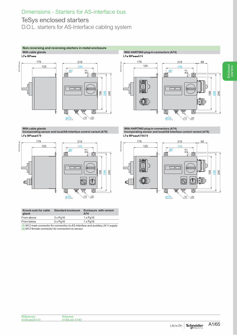
A1/65
Enc
lose
d st
arte
rs
References:A1/30 and A1/31
Schemes:A1/66 and A1/67
Non-reversing and reversing starters in metal enclosureWith cable glands With HARTING plug-in connectors (A74)
LFp MPppp LFp MPpppA74
8,5Ø7
Ø13 (1) (2)
179
125
199
230
245
175
219
DF5
1070
0.ep
s 179125
(1) (2)
199
230
245
175
219 60
8,5Ø7
Ø13D
F510
701.
eps
With cable glands Incorporating sensor and local/AS-Interface control variant (A79)
With HARTING plug-in connectors (A74)Incorporating sensor and local/AS-Interface control variant (A79)
LFp MPpppA79 LFp MPpppA79A74
8,5Ø7
Ø13 (1) (2)
199
230
245
175
219179
125
DF5
1070
2.ep
s 179
125
(1) (2)
199
8,5
230
245
175Ø7
Ø13
219 60
DF5
1070
3.ep
s
Knock-outs for cable gland
Standard enclosure Enclosure with variant A74
From above 3 x Pg16 1 x Pg16From below 2 x Pg16 1 x Pg16(1)M12maleconnectorforconnectiontoAS-Interfaceandauxiliary24Vsupply.(2)M12femaleconnectorforconnectiontosensor.
TeSys enclosed startersD.O.L. starters for AS-Interface cabling system
Dimensions - Starters for AS-interface bus
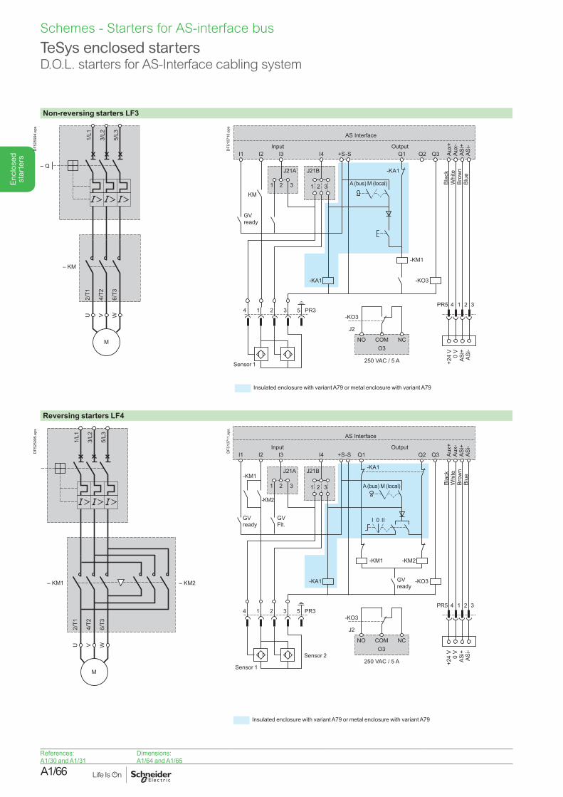
A1/66
Enc
lose
d st
arte
rs
Non-reversing starters LF3
DF5
2599
4.ep
s
I1
1KM
-KM1
-KA1
PR34 1 2 3PR5 4
NO
-KO3
J2
COMO3
250 VAC / 5 A
NC
1 2 35
-KA1
-KO3
32 1 32
I2 I3
J21A J21B
I4 +S-S Q1Output Input
AS Interface
Q2 Q3 Aux+
Aux-
ASi+
ASi-
+24
V0
VAS
i+AS
i-
Blac
kW
hite
A (bus) M (local)
GV ready
Blue
Brow
n
Sensor 1
Insulated enclosure with variant A79 or metal enclosure with variant A79
DF5
1071
0.ep
s
Reversing starters LF4
DF5
2599
5.ep
s
I1
1
I 0 II
-KM1
-KM1 -KM2
-KA1
PR34 1 2 3PR5 4
NO
-KO3
J2
COMO3
250 VAC / 5 A
NC
1 2 35
-KA1
-KO3
-KM2
32 1 32
I2 I3
J21A J21B
I4 +S-S Q1Output Input
AS Interface
Q2 Q3 Aux+
Aux-
ASi+
ASi-
+24
V0
VAS
i+AS
i-
GV ready
GV Flt.
Sensor 2
Sensor 1
GV ready
A (bus) M (local) Blac
kW
hite
Brow
nBl
ue
DF5
1071
1.ep
s
Insulated enclosure with variant A79 or metal enclosure with variant A79
TeSys enclosed startersD.O.L. starters for AS-Interface cabling system
References:A1/30 and A1/31
Dimensions:A1/64 and A1/65
Schemes - Starters for AS-interface bus
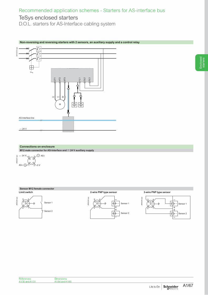
A1/67
Enc
lose
d st
arte
rs
TeSys enclosed startersD.O.L. starters for AS-Interface cabling system
Non-reversing and reversing starters with 2 sensors, an auxiliary supply and a control relay
AS-Interface line
DF5
1072
7.ep
s
References:A1/30 and A1/31
Dimensions:A1/64 and A1/65
Connections on enclosureM12 male connector for AS-Interface and c 24 V auxiliary supply
34
21
24 V AS-i
AS-i + 0 V
–
df56
5247
.eps
Sensor M12 female connector Limit switch 2-wire PNP type sensor 3-wire PNP type sensor
43
12
5 Sensor 1
Sensor 2
df56
5248
.eps
43
12
–
–
++
5Sensor 1
Sensor 2
df56
5249
.eps
–
–
++
43
12
5Sensor 1
Sensor 2
df56
5250
.eps
Recommended application schemes - Starters for AS-interface bus
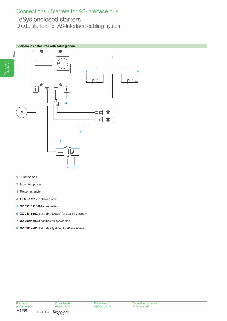
A1/68
Enc
lose
d st
arte
rs
Functions:A1/56 to A1/59
Characteristics:A1/60 to A1/63
References:A1/30 and A1/31
Dimensions, schemes:A1/64 to A1/67
Starters in enclosures with cable glands
M
1
2
5
3
7
8
6
4
DF5
1067
8.ep
s
1 Junction box
2 Incoming power
3 Power extension
4 FTX CY1212: splitter block
5 XZ CR1511040Ap: extension
6 XZ CB1pp02: flat cable (black) for auxiliary supply
7 XZ CG01403D: tap link for two cables
8 XZ CB1pp01: flat cable (yellow) for AS-Interface
TeSys enclosed startersD.O.L. starters for AS-Interface cabling system
Connections - Starters for AS-interface bus
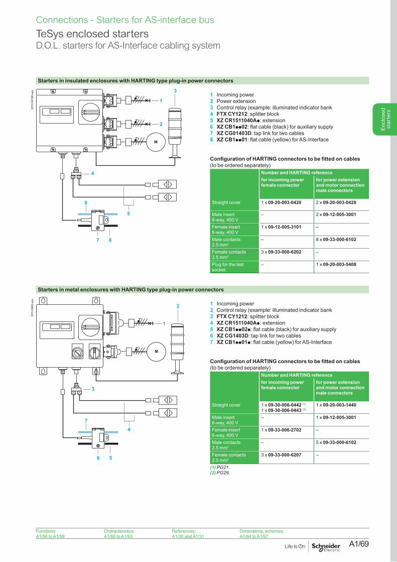
A1/69
Enc
lose
d st
arte
rs
Functions:A1/56 to A1/59
Characteristics:A1/60 to A1/63
References:A1/30 and A1/31
Dimensions, schemes:A1/64 to A1/67
Starters in insulated enclosures with HARTING type plug-in power connectors
M
3
4
1
2
5
7
8
6
DF5
1067
9R.e
ps 1 Incoming power2 Power extension3 Control relay (example: illuminated indicator bank4 FTX CY1212: splitter block5 XZ CR1511040Ap: extension6 XZ CB1pp02: flat cable (black) for auxiliary supply7 XZ CG01403D: tap link for two cables8 XZ CB1pp01: flat cable (yellow) for AS-Interface
Configuration of HARTING connectors to be fitted on cables (to be ordered separately)
Number and HARTING referencefor incoming power female connector
for power extension and motor connection male connectors
Straight cover 1 x 09-20-003-0420 2 x 09-20-003-0420
Male insert 6-way, 400 V
– 2 x 09-12-005-3001
Female insert 6-way, 400 V
1 x 09-12-005-3101 –
Male contacts 2.5 mm2
– 8 x 09-33-000-6102
Female contacts 2.5 mm2
3 x 09-33-000-6202 –
Plug for the last socket
– 1 x 09-20-003-5408
Starters in metal enclosures with HARTING type plug-in power connectors
M
2
3
1
4
6
7
5
DF5
1068
0.ep
s
1 Incoming power2 Control relay (example: illuminated indicator bank3 FTX CY1212: splitter block4 XZ CR1511040Ap: extension5 XZ CB1pp02p: flat cable (black) for auxiliary supply6 XZ CG1403D: tap link for two cables7 XZ CB1pp01p: flat cable (yellow) for AS-Interface
Configuration of HARTING connectors to be fitted on cables (to be ordered separately)
Number and HARTING referencefor incoming power female connector
for power extension and motor connection male connectors
Straight cover 1 x 09-30-006-0442 (1)
1 x 09-30-006-0443 (2)1 x 09-20-003-1440
Male insert 6-way, 400 V
– 1 x 09-12-005-3001
Female insert 6-way, 400 V
1 x 09-33-006-2702 –
Male contacts 2.5 mm2
– 5 x 09-33-000-6102
Female contacts 2.5 mm2
3 x 09-33-000-6207 –
(1)PG21.(2)PG29.
TeSys enclosed startersD.O.L. starters for AS-Interface cabling system
Connections - Starters for AS-interface bus

A1/70