Embed Size (px)
Citation preview
B6/1
Circ
uit
brea
kers
Circuit breakersTeSys GV, GB
Circuit breakers - TeSys GV, GBType of product Range Pages
Magnetic circuit breakers for motorsTeSys GV Up to 15, 30, 37 or 110 kW B6/2
Thermal magnetic circuit breakers for motorsTeSys GV
Up to 15, 30, 37 or 110 kW B6/4
Add-on blocks, accessories, for motor circuit breakers B6/10
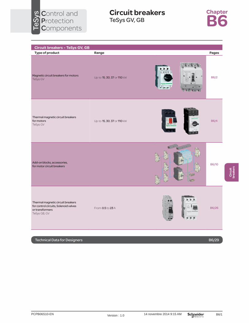
Thermal magnetic circuit breakers for control circuits, Solenoid valves or transformersTeSys GB, GV
From 0.5 to 23 A B6/26
TeSy
s Control and Protection Components
Chapter
B6
Technical Data for Designers B6/29
PCPB06S10-EN Version : 1.0 14 novembre 2014 9:15 AM

B6/6
TeSys GV
References
Motor circuit breakers from 0.06 to 30 kW / 400 V Standard power ratings of 3-phase motors 50/60 Hz in category AC-3
Setting range of thermal trips (2)
Magnetic tripping current Id ± 20 %
Reference
400/415 V 500 V 690 VP Icu Ics (1) P Icu Ics (1) P Icu Ics (1)
kW kA % kW kA % kW kA % A AGV2 P: control by rotary knobScrew clamp terminals
– – – – – – – – – 0.1…0.16 1.5 GV2P010.06 g g – – – – – – 0.16…0.25 2.4 GV2P020.09 g g – – – – – – 0.25…0.40 5 GV2P030.12 0.18
g g
g g
– –
– –
– –
0.37 –
g –
g –
0.40…0.63 8 GV2P04
0.25 g g – – – 0.55 g g 0.63…1 13 GV2P050.37 0.55
g g
g g
0.37 0.55
g g
g g
– 0.75
– g
– g
1…1.6 22.5 GV2P06
0.75 g g 1.1 g g 1.5 8 100 1.6…2.5 33.5 GV2P071.1 g g 1.5 g g 2.2 8 100 2.5…4 51 GV2P082.2 g g 3 g g 4 6 100 4…6.3 78 GV2P103 g g 5 50 100 5.5 6 100 6…10 138 GV2P145.5 –
g –
g –
7.5 –
42 –
75 –
9 11
6 6
100 100
9…14 170 GV2P16
7.5 50 50 9 10 75 15 4 100 13…18 223 GV2P209 50 50 11 10 75 18.5 4 100 17…23 327 GV2P2111 50 50 15 10 75 – – – 20…25 327 GV2P2215 35 50 18.5 10 75 22 4 100 24…32 416 GV2P32GV3 P: control by rotary knobConnection by EverLink® BTR screw connectors (3)
5.5 100 100 7.5 12 50 11 6 50 9…13 182 GV3P137.5 100 100 9 12 50 15 6 50 12…18 252 GV3P18 11 100 100 15 12 50 18.5 6 50 17…25 350 GV3P2515 100 100 18.5 12 50 22 6 50 23…32 448 GV3P3218.5 50 100 22 12 50 37 6 50 30…40 560 GV3P4022 50 100 30 12 50 45 6 50 37…50 700 GV3P5030 50 100 45 12 50 55 6 50 48…65 910 GV3P65Connection by EverLink® BTR screw connectors, for assembly with a contactor
To assemble a GV3 P13 to P65 circuit breaker with an LC1 D40A to D65A contactor, it is possible to use the circuit breaker supplied without downstream EverLink® power terminal block. To order this product, add the digit 1 to the end of the references selected above. Example: GV3 P65 becomes GV3 P651.Connection by lugs
To order thermal magnetic circuit breakers with connection by lugs, add the digit 6 to the end of reference selected above. Example: GV3 P18 becomes GV3 P186.GV3 ME80: pushbutton control, screw clamp terminals
37 15 50 45 4 100 55 2 100 56…80 GV3ME80 (4)
Motor circuit breakers up to 50 hp / 600 V, UL 508 type EGV2 (5)
To obtain a GV2 P motor circuit breaker, UL 508 type E, use the following with the circuit breaker:b a “Large Spacing” adapter GV2 GH7.GV3 (6)
To obtain a motor-circuit breaker GV3 P, UL 508 type E, use the following with the circuit breaker:b a “Large Spacing” cover GV3 G66,b a short-circuit signalling contact GV AM11.GV3 with connection by lugs (6)
To obtain a motor-circuit breaker GV3 P, UL 508 type E, with connection by lugs, add the digit 6 to the end of reference selected above and use the following with the circuit breaker:b two IP 20 covers LAD 96570,b a short-circuit signalling contact GV AM11.(1) As % of Icu.(2) The thermal trip setting must be within the range marked on the graduated knob.(3) BTR screws: hexagon socket head. Require use of an insulated Allen key, in compliance with local wiring regulations.(4) Recommended for use in association with a contactor.(5) Accessory: see page B6/13.(6) Accessories: see page B6/17.g > 100 kA.
TeSys protection componentsThermal-magnetic motor circuit breakers GV2 P, GV3 P and GV3 ME80
GV2 P10
DF5
2613
7.tif
GV3 P65
DF5
2613
9.tif
GV3 P651
DF5
2614
0.tif
Characteristics:pages B6/51, B6/52 and B6/55
Dimensions:pages B6/70 to B6/78
Schemes:pages B6/82 and B6/83
PCPB06P10-ENVersion : 1.0 14 novembre 2014 9:16 AM

B6/16
GV AM11
GV AM11
GV AE1
GV AE1
GV AE11, GV AE20,
GV3 L
GV3 P
GV3 G364
GV AE113, GV AE203, GV AED 1013, GV AED 0113
GV AED 101, GV AED 011
GV2 V03
GV3 G264
GV3 APN02
DB
1266
35.e
ps
PCPB06P10-ENVersion : 1.0 14 novembre 2014 9:16 AM

B6/17
Circ
uit
brea
kers
TeSys GV
Contact blocksDescription Mounting Maximum
numberType of contacts
Sold in lots of
Unit reference
Instantaneous auxiliary contacts
Front 1 N/O or N/C (1) 10 GVAE1N/O + N/C 10 GVAE11 (2)
N/O + N/O 10 GVAE20 (2)
Side (LH)
2 N/O + N/C 1 GVAN11 (2)
N/O + N/O 1 GVAN20 (2)
Fault signalling contact + instantaneous auxiliary contact
Front 1 N/O (fault) + N/O 1 GVAED101 (2)
N/O (fault) + N/C 1 GVAED011 (2)
Side (3)
(LH)1 N/O (fault) + N/O 1 GVAD1010
+ N/C 1 GVAD1001N/C (fault) + N/O 1 GVAD0110
+ N/C 1 GVAD0101Short-circuit signalling contact Side (LH) 1 C/O common point 1 GVAM11
Electric trips - undervotlage or shunt (4)
Mounting Voltage Reference
Side (1 block on RH side of circuit breaker)
24 V 50 Hz GVAp02560 Hz GVAp026
48 V 50 Hz GVAp05560 Hz GVAp056
100 50 Hz GVAp107100…110 V 60 Hz GVAp107110…115 V 50 Hz GVAp115
60 Hz GVAp116120…127 V 50 Hz GVAp125127 V 60 Hz GVAp115200 V 50 Hz GVAp207200…220 V 60 Hz GVAp207220…240 V 50 Hz GVAp225
60 Hz GVAp226380…400 V 50 Hz GVAp385
60 Hz GVAp386415…440 V 50 Hz GVAp415415 V 60 Hz GVAp416440 V 60 Hz GVAp385480 V 60 Hz GVAp415500 V 50 Hz GVAp505600 V 60 Hz GVAp505
AccessoriesDescription Reference
Sets of 3-pole 115 A busbarsPitch: 64 mm
2 tap-off GV3 Ppp and GV3 Lpp GV3G2643 tap-off GV3 Ppp and GV3 Lpp GV3G364
Cover “Large Spacing” UL 508 type E(Only one cover required on supply side)
GV3 Ppp GV3G66
(1) Choice of N/C or N/O contact operation, depending on which way round the reversible block is mounted.(2) 3 at the end of the references selected above.
Example: GV AED101 becomes GV AED1013.(3) The GV ADpp is always mounted next to the circuit breaker.(4) To order an undervoltage trip: replace the dot (p) in the reference with a U, example: GV AU025.
To order a shunt trip: replace the dot (p) in the reference with an S, example: GV AS025.
References TeSys protection componentsThermal-magnetic motor circuit breakers GV3 P and GV3 LAdd-on blocks and accessories
GV3 G66
DF5
3742
4.ep
s
PCPB06P10-EN Version : 1.0 14 novembre 2014 9:16 AM

B6/18
TeSys GV
1
DB
1266
37.e
ps
5
3 2
4
DB
1266
36.e
ps
6
DB
1266
32.e
ps
7
PB10
6297
_45.
eps
Extended Rotary HandleAllows a circuit breaker or a starter-controller installed in back of an enclosure to be operated from the front of the enclosure.A rotary handle can be black or red/yellow, IP54 or IP65. It includes a function for locking the circuit breaker or the starter in the O (Off) or I (On) position (depending of the type of rotary handle) by means of up to 3 padlocks with a shank diameter of 4 to 8 mm. The extended shaft must be adjusted to use in different size
the assembling. The new Laser Square tool brings the accurency to align the circuit breaker and the rotary handle.
Padlockable external operators for GV3 and GV3LDescription
1 Kit handle + mounting system2 Universal handle3 Shaft4 Bracket5 Shaft support plate for deep enclosure6 7 Laser Square accessory
Kit handle + mounting systemDescription Item Reference
For GV3 P/L Black handle, front plate, with trip status, IP 54 1 GV3APN01Red handle, front plate, with trip status, IP 54 1 GV3APN02Red handle, front plate, without trip status, IP 65 1 GV3APN04
Universal handleFor GV3 P/L Black handle, IP 54 2 GVAPB54
Red handle, IP 54 2 GVAPR54Red handle, IP 65 2 GVAPR65
ShaftFor GV3 P/L L = 315 mm 3 GVAPA1Bracket
For GV3 P/L 4 GVAPH03Shaft support plate for deep enclosure
For GV3 P/L Depth u 300 mm 5 GVAPK12
For GV3 P/L 6 GVAPP1Laser Square accessory
For GV3 P/L 7 GVAPL01Sticker Sold in lots of
Warning label For French 10 - GVAPSFRFor English 10 - GVAPSENFor German 10 - GVAPSDEFor Spanish 10 - GVAPSESFor Chinese 10 - GVAPSCNFor Portuguese 10 - GVAPSPTFor Russian 10 - GVAPSRUFor Italian 10 - GVAPSIT
References TeSys protection componentsThermal-magnetic motor circuit breakers GV3 P and GV3 L
PCPB06P10-ENVersion : 1.0 14 novembre 2014 9:16 AM
B6/20
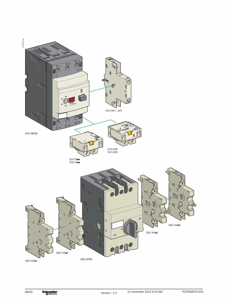
GV3 A08GV3 A09
GV3 A01...A07
DF5
2634
2.ep
s
PCPB06P10-ENVersion : 1.0 14 novembre 2014 9:16 AM

B6/21
Circ
uit
brea
kers
TeSys GV
For thermal-magnetic motor circuit breakers GV3 ME80Contact blocksDescription Type of standard
early break contactsReference
Instantaneous auxiliary contact blocks (1 per circuit breaker)
N/C + N/O GV3A01N/O + N/O GV3A02N/C + N/O + N/O GV3A03N/O + N/O + N/O GV3A05N/O + N/O + 2 volt-free terminals GV3A06N/C + N/O + 2 volt-free terminals GV3A07
Fault signalling contacts (1) N/C GV3A08N/O GV3A09
Electric tripsDescription Voltages Reference
50 Hz 60 HzUdervoltage trips (1) 110, 120, 127 V 120, 127 V GV3B11
220, 240 V 277 V GV3B22380, 415 V 440 V, 480 V GV3B38
Shunt trips (1) 110, 120, 127 V 120, 127 V GV3D11220, 240 V 277 V GV3D22380, 415 V 440 V, 480 V GV3D38
AccessoryDescription Sold in
lots ofUnit reference
Padlocking device, for locking the Start button (on open-mounted product)
5 GV1V02
For magnetic circuit breaker GK3 EF80Contact blocksDescription Number of poles Reference
Auxiliary contact blocks for On-Off signalling and “control circuit test” function (1 or 2 blocks per device) mounted on RH side of GK3 EF80
N/O GK2AX10N/O + N/O GK2AX20N/C + N/O GK2AX50
Instantaneous fault signalling contact blocks (1 or 2 blocks per device) mounted on LH side of GK3 EF80
N/O GK2AX12N/O + N/O GK2AX22N/C + N/O GK2AX52
AccessoriesDescription Reference
Padlocking device for padlocking the operator, using up to 3 padlocks (padlocks to be ordered separately)
GK3AV01
External operator for mounting on enclosure door.
(with up to 3 padlocks). Door locked when knob in position I, and when knob padlocked in position O.
GK3AP03
(1) 1 voltage trip OR
Other versions
24 to 690 V, 50 or 60 Hz voltage trips for circuit breakers GV3 ME80.
References TeSys protection componentsMotor circuit breakers GV3 ME80 and GK3 EF80Add-on blocks and accessories
Characteristics:pages B6/89 and B6/92
Dimensions:page B6/47
PCPB06P10-EN Version : 1.0 14 novembre 2014 9:16 AM
B6/22
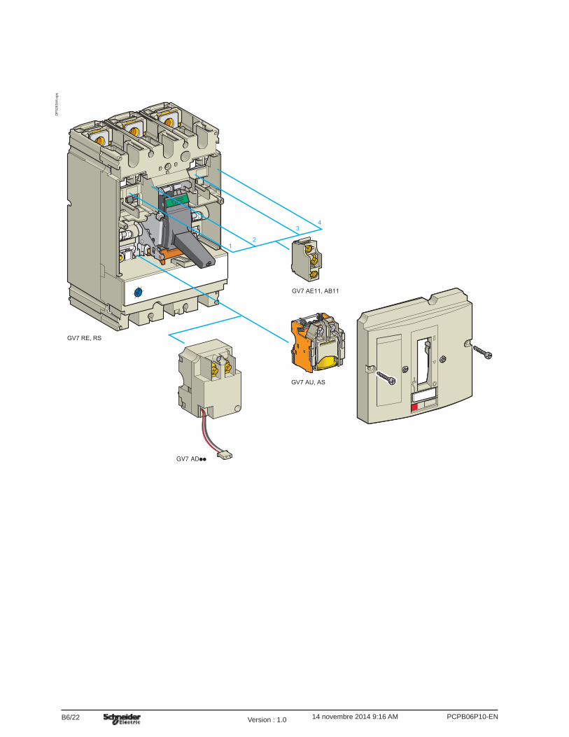
GV7 RE, RS
GV7 AE11, AB11
GV7 AU, AS
12
34
DF5
2634
4.ep
s
PCPB06P10-ENVersion : 1.0 14 novembre 2014 9:16 AM

B6/24
ON
OFFO
ON
OFFO
ON
OFFO
OFFO
ON
ON
OFFO
GV7 RE, RS
GV7 AP03
OFFO
ON
GV7 AP04
GV7 AP01, AP02
GV7 V01
GV7 AP05
GV7 RE, RS
GV7 AC01
GV7 AC03 GV7 AC01
GV7 AC04
GV7 AC04
DF5
2634
3.ep
s
PCPB06P10-ENVersion : 1.0 14 novembre 2014 9:16 AM

PCPB06T10-ENVersion : 1.0 14 novembre 2014 9:14 AMB6/32
TeSys GV
Characteristics
EnvironmentCircuit breaker type GV3 L GK3 EF80
Conforming to standards IEC/EN 60947-1, 60947-2 IEC 60947-2, EN 60204
Protective treatment “TH” “TC”
Degree of protection (front face)
Conforming to IEC 60529
Shock resistance Conforming to IEC 60068-2-27
On : 15 gn -11 msOff : 30 gn -11 ms
22 gn -20 ms
Vibration resistance Conforming to IEC 60068-2-6
4 gn (5…300 Hz) 2.5 gn (0…25 Hz)
Flame resistance Conforming to IEC 60695-2-1
°C 960 960
Ambient air temperature Storage °C -40…+80 -40…+ 80
Operation °C -20…+60 (1) -20…+ 70 open mounted
Maximum operating altitude m 3000 3000
Operating positionWithout derating, in relation to normal vertical mounting plane (2)
D
F534
074.
eps Any position
Connection(Max. number of conductors x c.s.a)
Min. Max. Min. Max.Solid cable mm2 2 x 1 1 x 25
1 x 351 x 2.5 1 x 35
Flexible cable without cable end
mm2 2 x 1 1 x 25 1 x 35
1 x 2.5 or 2 x 2.5
1 x 25 or 2 x 16
Flexible cable with cable end
mm2 2 x 1 1 x 25 1 x 35
1 x 2.5 or 2 x 2.5
1 x 25 or 2 x 16
Tightening torque N.m 5 5 : 25 mm2
8 : 35 mm25
Suitable for isolationconforming to IEC 60947-1 § 7-1-6
Yes Yes
Technical characteristicsRated insulation voltage (Ui)
Conforming to IEC 60947-2 V 690 750
Rated impulse withstand voltage (U imp)
Conforming to IEC 60947-2 kV 6 10
Rated operational voltage (Ue)
Conforming to IEC 60947-2 V 690 690
Rated operational frequency Hz 50/60 50…60
Electrical durability for AC-3/415V duty (C.O.: Close - Open)
C.O. 50 000 1500
Mechanical durability (C.O.: Closing, Opening)
C.O. 50 000 20 000
Maximum operating rate C.O./h 25 40
Operating threshold of magnetic trips 14 I max 3363
Utilisation category Conforming to IEC 60947-2 A A
(1) Leave a space of 9 mm between 2 circuit breakers: either an empty space or side-mounting add-on contact blocks. Side by side mounting is possible up to 40 °C.
(2)
TeSys protection componentsMagnetic motor circuit breakers GV3 L and GK3 EF80
References:pages B6/2 and B6/3
Dimensions:pages B6/43 to B6/47
Schemes:page B6/48

PCPB06T10-EN Version : 1.0 14 novembre 2014 9:14 AM B6/33
Circ
uit
brea
kers
B6/33
TeSys GV
Breaking capacity of GV3 L and GK3 EF80Type GV3 L25 GV3 L32 GV3 L40 GV3 L50 GV3 L65 GK3 EF80
Breaking capacity of the circuit-breaker only or of the circuit-breaker combined with a thermal overload relay
230/240 V Icu kA 100 100 100 100 100 50
Ics % (1) 100 100 100 100 100 40
400/415 V Icu kA 100 100 50 50 50 35
Ics % (1) 100 100 100 100 100 25
440 V Icu kA 50 50 50 50 50 25
Ics % (1) 100 100 100 100 100 30
500 V Icu kA 12 12 12 12 12 15
Ics % (1) 50 50 50 50 50 30
690 V Icu kA 6 6 6 6 6 6
Ics % (1) 50 50 50 50 50 50
Associated fuses (if required) for use with circuit breaker only or circuit breaker combined with a thermal overload relay if lsc > breaking capacity
230/240 V aM A g g g g g 200
gG A g g g g g 315
415 V aM A g g g g 125 200
gG A g g g g 160 250
440 V aM A 63 80 125 125 125 160
gG A 80 100 160 160 160 250
500 V aM A 63 63 63 63 80 160
gG A 80 80 80 80 100 200
690 V aM A 50 50 50 50 63 125
gG A 63 63 63 63 80 160
Use of circuit breakers without fuses Minimum cable length (in metres) limiting the maximum short-circuit current to 35 kA maximum, so enabling breakers GK3 EF80 to be used without fuses
Cable c.s.a. mm2 y 25 35 50 70 95 120
Isc (rms) 3-phase, incoming (Ue = 415 V)
50 kA m 5 6 8 10 13 15
45 kA m 5 5 7 8 10 12
40 kA m 5 5 5 5 8 9
37 kA m 5 5 5 5 5 5
g Fuse not required: breaking capacity Icn > Isc.(1) As % of Icu.
Characteristics TeSys protection componentsMagnetic motor circuit breakers GV3 L and GK3 EF80
References:pages B6/2 and B6/3
Dimensions:pages B6/43 to B6/47
Schemes:page B6/48

PCPB06T10-ENVersion : 1.0 14 novembre 2014 9:14 AMB6/40
TeSys GV
Curves
Tripping curves for GV3 L and GK3 EF80 combined with thermal overload relay LRD 33
10
10 000
1
0,1
0,0011 10 100
1000
100
0,01
32
1
B
A
Time (s)
x the setting current (Ir)
DF5
3409
8.ep
s
1 3 poles from cold state2 2 poles from cold state3 3 poles from hot state
A Thermal overload relay protection zoneB GK3 EF80 and GV3 L protection zone
TeSys protection componentsMagnetic motor circuit breakers GV3 L and GK3 EF80
References:pages B6/2 and B6/3
Dimensions:pages B6/43 to B6/47
Schemes:page B6/48

PCPB06T10-EN Version : 1.0 14 novembre 2014 9:14 AM B6/41
Circ
uit
brea
kers
B6/41
TeSys GV
Curves
Current limitation on short-circuit for GV3 L and GK3 EF80 (3-phase 400/415 V)Dynamic stress
I peak = f (prospective Isc) at 1.05 Ue = 435 V
11 10 100
10
50
2
1
543
76
Limited peak current (kA)
Prospective Isc (kA)
DF5
6681
7.ep
s
1 Maximum peak current2 GK3 EF803 GV3 L654 GV3 L505 GV3 L406 GV3 L327 GV3 L25
TeSys protection componentsMagnetic motor circuit breakers GV3 L and GK3 EF80
References:pages B6/2 and B6/3
Dimensions:pages B6/43 to B6/47
Schemes:page B6/48

PCPB06T10-ENVersion : 1.0 14 novembre 2014 9:14 AMB6/42
TeSys GV
Curves
Thermal limit on short-circuit for GV3 L and GK3 EF80Thermal limit in A2s
Sum of I2dt = f (prospective Isc) at 1.05 Ue = 435 V
10
11 10 100
100
1000
1
432
56
Sum of I2dt (A2s)
Prospective Isc (kA)
DF5
6681
8.ep
s
1 GK3 EF802 GV3 L653 GV3 L504 GV3 L405 GV3 L326 GV3 L25
TeSys protection componentsMagnetic motor circuit breakers GV3 L and GK3 EF80
References:pages B6/2 and B6/3
Dimensions:pages B6/43 to B6/47
Schemes:page B6/48
PCPB06T10-ENVersion : 1.0 14 novembre 2014 9:14 AMB6/46
TeSys GV
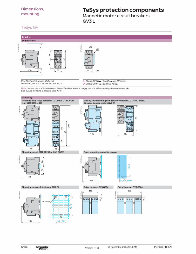
GV3 LDimensions
136
X1
X1
132
6864
55
DF5
3748
0.ep
s
9 18
(2)(1)
DF5
3748
1.ep
sX1 = Electrical clearance (ISC max) 40 mm for Ue y 500 V, 50 mm for Ue y 690 V
(1) Blocks GV ANpp , GV ADpp and GV AM11.(2) Blocks GV3 AUpp and GV3 ASpp.
Note: Leave a space of 9 mm between 2 circuit breakers: either an empty space or side-mounting add-on contact blocks. Side by side mounting is possible up to 40 °C.
MountingMounting with Tesys contactor LC1 D40A…D65A and relay LR3 D313…365
Side by side mounting with Tesys contactor LC1 D40A…D65A(S-shape busbar system GV3 S)
185
299
7011
5
136 55
DF5
6774
4.ep
s
136 11919
5
DF5
6774
5.ep
s
Mounting on rail AM1 DE200 or AM1 ED201 Panel mounting, using M4 screws
144
6864
DF5
3748
2.ep
s
136 3xØ4
137,
5
37,5
DF5
6774
8.ep
s
Mounting on pre-slotted plate AM1 PA Set of busbars GV3 G264 Set of busbars GV3 G364
136 18,7 18,7
137,
5
AF1 EA4
DF5
3743
5.ep
s 119
16
DF5
1063
7.ep
s 183
16
DF5
1063
8.ep
s
Dimensions, mounting
TeSys protection componentsMagnetic motor circuit breakers GV3 L
PCPB06T10-EN Version : 1.0 14 novembre 2014 9:14 AM B6/47
Circ
uit
brea
kers
B6/47
TeSys GV
Dimensions, mounting
TeSys protection componentsMagnetic motor circuit breakers GV3 L and GK3 EF80
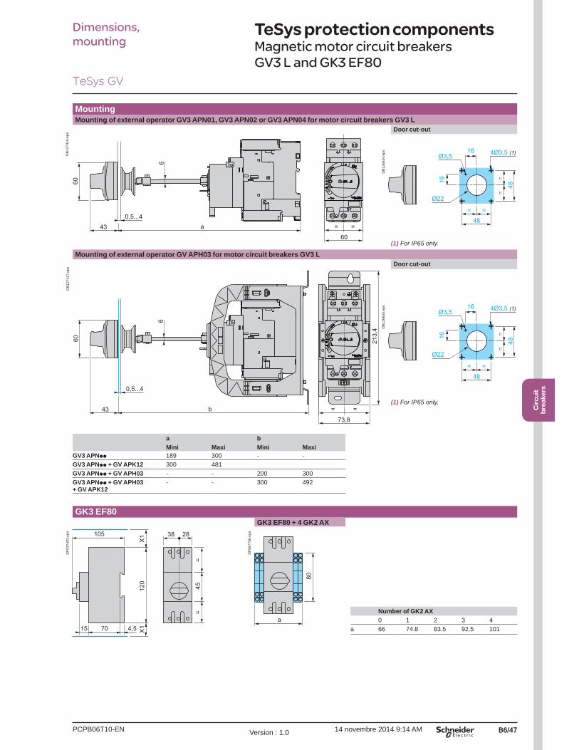
MountingMounting of external operator GV3 APN01, GV3 APN02 or GV3 APN04 for motor circuit breakers GV3 L
0,5...443
60
a
60
6
= =
DB
1274
16.e
ps
Door cut-out
48= =
==
48
4Ø3,5 (1)16
16
Ø3,5
Ø22
DB
1266
34.e
ps
Mounting of external operator GV APH03 for motor circuit breakers GV3 L
0,5...4
43 b
60
6
213,
4
73,8
= =
DB
1274
17.e
ps
Door cut-out
48= =
==
48
4Ø3,5 (1)16
16
Ø3,5
Ø22
DB
1266
34.e
ps
a bMini Maxi Mini Maxi
GV3 APNpp 189 300 - -GV3 APNpp + GV APK12 300 481GV3 APNpp + GV APH03 - - 200 300GV3 APNpp + GV APH03 + GV APK12
- - 300 492
GK3 EF80GK3 EF80 + 4 GK2 AX
70 4,515
120
X1
X1
105 38 28
45=
=
DF5
3748
3.ep
s
a
80
DF5
6775
6.ep
s
Number of GK2 AX0 1 2 3 4
a 66 74.8 83.5 92.5 101
(1) For IP65 only.
(1) For IP65 only.
PCPB06T10-ENVersion : 1.0 14 novembre 2014 9:14 AMB6/48
TeSys GV
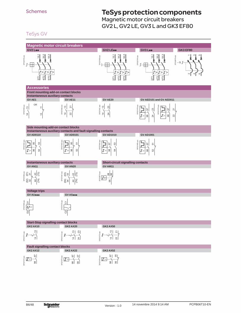
Schemes TeSys protection components0
Magnetic motor circuit breakers GV2 L, GV2 LE, GV3 L and GK3 EF80
Magnetic motor circuit breakersGV2 Lpp GV2 LEpp GV3 Lpp GK3 EF80
2/T1
4/T2
6/T3
1/L1
3/L2
5/L3
DF5
1074
4.ep
s
2/T1
4/T2
6/T3
1/L1
3/L2
5/L3
DF5
3745
8.ep
s
2/T1
4/T2
6/T3
1/L1
3/L2
5/L3
DF5
1074
4.ep
s
DF5
1067
5.ep
s
AccessoriesFront mounting add-on contact blocks Instantaneous auxiliary contactsGV AE1 GV AE11 GV AE20 GV AED101 and GV AED011
1314 12
11
OR
DF5
3745
9.ep
s
DF5
3746
0.ep
s
1314 22
21 1314
2324D
F537
461.
eps
9798
2324
DF5
3747
8.ep
s
9798
2122
DF5
3747
9.ep
s
Side mounting add-on contact blocks Instantaneous auxiliary contacts and fault signalling contactsGV AD0110 GV AD0101 GV AD1010 GV AD1001
535496
95
DF5
3746
2.ep
s
5251
9695
DF5
3746
3.ep
s
9798
5354
DF5
3746
4.ep
s
9798
5152
DF5
3746
5.ep
s
Instantaneous auxiliary contacts Short-circuit signalling contactsGV AN11 GV AN20 GV AM11
(62) 32
(61) 31 43 (73)
44 (74)DF5
3746
6.ep
s
(64) 34
(63) 33 43 (73)
44 (74)D
F537
467.
eps
050608
DF5
1067
4.ep
s
Voltage tripsGV AUppp GV ASppp
D1
D2
DF5
3746
9.ep
s
DF5
3747
0.ep
s
C1
C2
Start-Stop signalling contact blocksGK2 AX10 GK2 AX20 GK2 AX50
1314
DF5
3747
1.ep
s 1314
2324
DF5
3747
2.ep
s
222113
14
DF5
3747
3.ep
s
Fault signalling contact blocksGK2 AX12 GK2 AX22 GK2 AX52
9798
DF5
3747
4.ep
s 9798
0708
DF5
3747
5.ep
s 9798 06
05
DF5
3747
6.ep
s

PCPB06T20-EN Version : 1.0 14 novembre 2014 9:13 AM B6/49
Circ
uit
brea
kers
TeSys GV
B6/49
Presentation
PresentationGV2 ME, GV2 P, GV3 ME, GV3 P and GV7 R motor circuit breakers are 3-pole thermal-magnetic circuit breakers protection of motors, conforming to standards IEC 60947-2 and IEC 60947-4-1. ConnectionGV2
GV2 ME and GV2 P circuit breakers are designed for connection by screw clamp terminals.Circuit breaker GV2 ME can be supplied with lugs or spring terminal connections.Spring terminal connections ensure secure, permanent and durable clamping that is resistant to harsh environments, vibration and impact and are even more effective when conductors without cable ends are used. Each connection can take two independent conductors.
GV3GV3 circuit breakers feature connection by BTR screws (hexagon socket head), tightened using a n° 4 Allen key. This type of connection uses the EverLink® system with creep compensation (1) (Schneider Electric patent).This technique makes it possible to achieve accurate and durable tightening torque, in order to avoid cable creep.
GV3 circuit breakers are also available with connection by lugs. This type of connection meets the requirements of certain Asian markets and is suitable for applications subject to strong vibration, such as railway transport.
GV7GV7 circuit breakers: with connection by screw clamp terminals (for bars and lugs) and by clip-on connectors. Operation
Control is manual and local when the motor circuit breaker is used on its own.Control is automatic and remote when it is associated with a contactor. GV2 ME and GV3 ME80
Pushbutton control.Energisation is controlled manually by operating the Start button “I” 1.De-energisation is controlled manually by operating the Stop button “O” 2, or automatically by the thermal-magnetic protection elements or by a voltage trip attachment. GV2 P, GV3 P and GV7 Rb Control by rotary knob: for GV2 P and GV3 Pb Control by rocker lever: for GV7 R.
Energisation is controlled manually by moving the knob or rocker lever to position “I” 1.De-energisation is controlled manually by moving the knob or rocker lever to position “O” 2.De-energisation due to a fault automatically places the knob or rocker lever in the “Trip” position 3.Re-energisation is possible only after having returned the knob or rocker lever to position “O”.
(1) Creep: normal crushing phenomenon of copper conductors, that is accentuated over time.
TeSys protection componentsThermal-magnetic motor circuit breakers GV2, GV3 and GV7
GV2 ME with screw clamp terminals
1
2
4
DF5
2613
4.tif
GV2 ME with spring terminals connections
1
2
4
DF5
2613
5.tif
GV3 P
132
4
DF5
2613
6.tif
GV2 P
13
4
2
DF5
2613
7.tif
GV7 R
1
3
2
DF5
2613
8.tif
Characteristics:pages B6/51 to B6/56
References:pages B6/4 to B6/9
Dimensions and schemes:pages B6/70 to B6/83
PCPB06T20-ENVersion : 1.0 14 novembre 2014 9:13 AM
TeSys GV
B6/50
Presentation
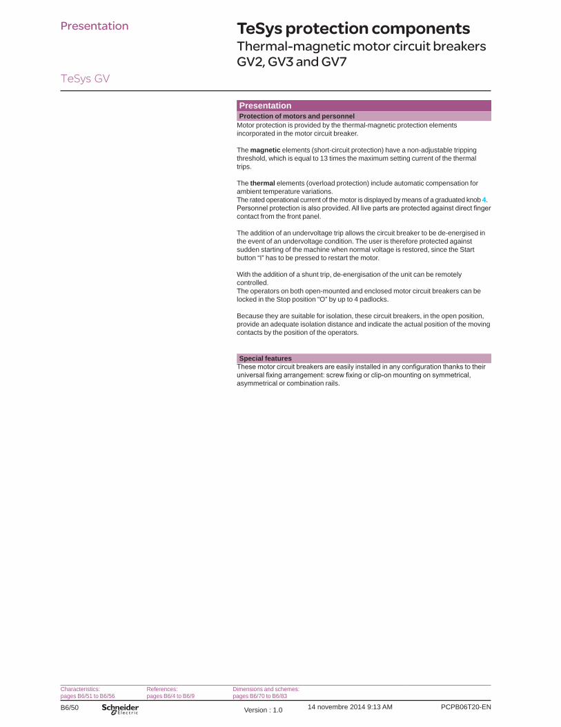
PresentationProtection of motors and personnel
Motor protection is provided by the thermal-magnetic protection elements incorporated in the motor circuit breaker.
The magnetic elements (short-circuit protection) have a non-adjustable tripping threshold, which is equal to 13 times the maximum setting current of the thermal trips.
The thermal elements (overload protection) include automatic compensation for ambient temperature variations.The rated operational current of the motor is displayed by means of a graduated knob 4.
contact from the front panel.
The addition of an undervoltage trip allows the circuit breaker to be de-energised in the event of an undervoltage condition. The user is therefore protected against sudden starting of the machine when normal voltage is restored, since the Start button “I” has to be pressed to restart the motor.
With the addition of a shunt trip, de-energisation of the unit can be remotely controlled.The operators on both open-mounted and enclosed motor circuit breakers can be locked in the Stop position “O” by up to 4 padlocks.
Because they are suitable for isolation, these circuit breakers, in the open position, provide an adequate isolation distance and indicate the actual position of the moving contacts by the position of the operators.
Special features
asymmetrical or combination rails.
TeSys protection componentsThermal-magnetic motor circuit breakers GV2, GV3 and GV7
Characteristics:pages B6/51 to B6/56
References:pages B6/4 to B6/9
Dimensions and schemes:pages B6/70 to B6/83
PCPB06T20-EN Version : 1.0 14 novembre 2014 9:13 AM B6/51
Circ
uit
brea
kers
TeSys GV
B6/51
Characteristics
EnvironmentCircuit breaker type GV2 ME GV2 P GV3 P GV3 ME80 GV7 R
Conforming to standards IEC 60947-1, 60947-2, 60947-4-1, EN 60204, UL 508, CSA C 22.2 n° 14-05, NF C 63-650, 63-120, 79-130, VDE 0113, 0660
IEC/EN 60947-1, 60947-2, 60947-4-1, UL 508 type E, CSA C 22.2 n° 14-05 type E
IEC/EN, NF EN, BS EN, DIN EN 60947-2, 60947-4-1
IEC 60947-1, 60947-2, 60947-4-1, EN 60947-1, 60947-2, EN 60947-4-1, NF C 63-650, NF C 63-120, 79-130, VDE 0113, 0660
UL, CSA, CCC, CEBEC, GOST, TSE, BV, GL, LROS , DNV, PTB, EZU, SETI, RINA, ATEX
UL (1), CSA, PTB, EZU, GOST, TSE, DNV, LROS, GL, BV, RINA, CCC, ATEX
UL, CSA, CCC (pending), GOST,ATEX, GL, BV, LROS (DNV, RINA pending)
UL, CSA, LROS
UL, DNV, CCC
Protective treatment “TH” “TH” “TC” “TC”Degree of protection (front face)
Conforming to IEC 60529
Open mounted IP20
Against direct
IP20
Against direct
IP20
IP405 with terminal shrouds
In enclosure GV2 Mp01: IP41 GV2 Mp02: IP55
– GV3 PC01 and GV3 PC02: IP55
GV3 CE01: IP55
–
Shock resistance Conforming to IEC 60068-2-27 30 gn -11 ms On: 15 gn -11 ms Off: 30 gn -11 ms
22 gn - 20 ms 15 gn -11 ms
Vibration resistance Conforming to IEC 60068-2-6 5 gn (5…150 Hz) 4 gn (5…300 Hz)
2.5 gn (0…25 Hz)
2.5 gn (25 Hz)
Ambient air temperature Storage °C -40…+80 -40…+80 -40…+80 -40…+80 -55…+95Operation Open mounted °C -20…+60 -20…+60 -20…+60 (2) -20…+60 -25… +70
In enclosure °C -20…+40 -20…+40 -20…+40 -20…+40 –Temperature compensation Open mounted °C -20…+60 -20…+60 -20…+60 -20…+60 -25… +55 (3)
In enclosure °C -20…+40 -20…+40 -20…+40 -20…+40 –Flame resistance Conforming to IEC 60695-2-1 °C 960 960 960 960Maximum operating altitude m 2000 3000 3000 2000Suitable for isolation Conforming to IEC 60947-1 § 7-1-6 Yes Yes – YesResistance to mechanical impact J 0.5 0.5 10 0.5 0.5
IK04 IK09 (in enclosure)
– –
Sensitivity to phase failure Yes, conforming to IEC 60947-4-1 § 7-2-1-5-2
Technical characteristicsCircuit breaker type GV2 ME GV2 P GV2 RT GV3 P GV3
ME80GV7 Rp20... Rp100
GV7 Rp150
GV7 Rp220
Utilisation category Conforming to IEC 60947-2 A A A AConforming to IEC 60947-4-1 AC-3 AC-3 AC-3 AC-3
Rated operational voltage(Ue)
Conforming to IEC 60947-2 V 690 690 690 690
Rated insulation voltage (Ui) Conforming to IEC 60947-2 V 690 690 690 750Rated voltage Conforming to CSA C22-2 n° 14,
UL 508V 600 600 600
(B600)600
Rated operational frequency Conforming to IEC 60947-4-1 UL, CSA
Hz 50/60 50/60 50/60 50/60
Rated impulse withstand voltage (U imp)
Conforming to IEC 60947-2 kV 6 6 6 8
Total power dissipated per pole W 2.5 8 8 5 8.7 14.5Mechanical durability (C.O.: Close, Open)
C.O. 100 000 50 000 30 000 50 000 40 000 20 000
Electrical durability for AC-3 duty
440 V In/2 C.O. 100 000 – 30 000 50 000 40 000 20 000440 V In C.O. – 50 000 – 30 000 20 000 10 000
Duty class (maximum operating rate) C.O./h 25 25 25 25Maximum conventional rated thermal current (Ith)
Conforming to IEC 60947-4-1 A 0.16… 32
0.16… 32
0.40… 23
13… 65
80 12… 100
150 220
Rated duty Conforming to IEC 60947-4-1 Continuous duty(1) UL 508 type E for GV2 PppH7.(2) Leave a space of 9 mm between 2 circuit breakers: either an empty space, or side mounting
add-on contact blocks. Side by side mounting is possible up to 40 °C.(3)
TeSys protection componentsThermal-magnetic motor circuit breakers
References:pages B6/4 to B6/9
Dimensions:pages B6/70 to B6/81
Schemes:pages B6/82 and B6/83

PCPB06T20-ENVersion : 1.0 14 novembre 2014 9:13 AM
TeSys GV
B6/52
Characteristics
Mounting characteristicsOperating position Without derating, in relation to normal vertical mounting plane (1)
90˚ 90˚90
˚ 90˚
DF5
1052
0.ep
s
Connection characteristicsConnection to screw clamp terminals or spring terminals
Bare cables
h
DF5
1055
4.ep
s
Circuit breaker type GV2 ME GV2 P GV3 P GV3 ME80Connection to screw clamp terminals (2) (Max. number of conductors x c.s.a.)
Min. Max. Min. Max. Min. Max. Min. Max.Solid cable mm2 2 x 1 2 x 6 2 x 1 2 x 6 2 x 1 1 x 25 and
1 x 351 x 2.5 1 x 35
Flexible cable without cable end
mm2 2 x 1.5 2 x 6 2 x 1.5 2 x 6 2 x 1 1 x 25 and 1 x 35
1 x 2.5 2 x 16
Flexible cable with cable end
mm2 2 x 1 2 x 4 2 x 1 2 x 4 2 x 1 1 x 25 and 1 x 35
1 x 2.5 2 x 16
Tightening torque N.m 1.7 1.7 1.7 1.7 5 5: 25 mm2
8: 35 mm25 5
Connection to spring terminals Number of conductors x c.s.a.
Solid cable mm2 2 x 1 (3) 2 x 6 – – – – – –
Flexible cable without cable end
mm2 2 x 1.5 (3) 2 x 4 – – – – – –
Connection by bars or lugsBars or lugs
e
d
L
DF5
3404
6.ep
s
d
L
DF5
3404
7.ep
s
L'
Ø6DF5
1061
5.ep
s
Circuit breaker type GV2 MEpp6 GV3 Ppp6 GV7 Rp20...Rp100
GV7 Rp150 GV7 Rp220
Pitch Without spreaders mm 13.5 17.5 35 35 35
With spreaders mm – – 45 45 45
Bars or cables with lugs e mm y 6 y 6 y 6 y 6 y 6
L mm y 9.5 y 13.5 y 25 y 25 y 25
L’ mm y 9.5 y 16.5 – – –
d mm y 10 y 10 y 10 y 10 y 10
Screws M4 M6 M6 M8 M8
Tightening torque N.m 1.7 6 10 15 15
Bare cables (copper or aluminium) with connectors
Height (h) mm – – 20 20 20
C.s.a. mm2 – – 1.5...95 1.5...95 1.5...185
Tightening torque N.m – – 15 15 15
(1)(2) For motor circuit breakers GV3 P: BTR hexagon socket head screws, EverLink® system.
Require use of an insulated Allen key, in compliance with local electrical wiring regulations.(3) For cross-sections 1 to 1.5 mm2, the use of an LA9 D99 cable end reducer is recommended.
References:pages B6/4 to B6/9
Dimensions:pages B6/70 to B6/81
Schemes:pages B6/82 and B6/83
TeSys protection componentsThermal-magnetic motor circuit breakers

PCPB06T20-EN Version : 1.0 14 novembre 2014 9:13 AM B6/55
Circ
uit
brea
kers
TeSys GV
B6/55
Characteristics
Breaking capacity of GV3 P and GV3 ME80Motor circuit breaker type GV3 P GV3 ME80
13 18 25 32 40 50 65Rating A 13 18 25 32 40 50 65 80
Breaking capacity conforming to IEC 60947-2
230/240 V Icu kA 100 100 100 100 100 100 100 100
Ics % (1) 100 100 100 100 100 100 100 100
400/415 V Icu kA 100 100 100 100 50 50 50 15
Ics % (1) 100 100 100 100 100 100 100 50
440 V Icu kA 50 50 50 50 50 50 50 10
Ics % (1) 100 100 100 100 100 100 100 60
500 V Icu kA 12 12 12 12 12 12 12 4
Ics % (1) 50 50 50 50 50 50 50 100
690 V Icu kA 6 6 6 6 6 6 6 2
Ics % (1) 50 50 50 50 50 50 50 100
Associated fuses, if required if lsc > breaking capacity Icu
230/240 V aM A g g g g g g g g
gG A g g g g g g g g
415 V aM A g g g g 125 125 125 315
gG A g g g g 160 160 160 400
440 V aM A 63 80 125 125 125 125 125 315
gG A 80 100 160 160 160 160 160 400
500 V aM A 63 63 63 63 80 80 80 200
gG A 80 80 80 80 100 100 100 250
690 V aM A 50 50 50 50 63 63 63 200
gG A 63 63 63 63 80 80 80 250
g Fuse not required: breaking capacity Icn > Isc.(1) As % of Icu.
TeSys protection componentsThermal-magnetic motor circuit breakers GV3 P and GV3 ME80
References:page B6/6
Dimensions:pages B6/76 to B6/78
Schemes:pages B6/82 and B6/83
PCPB06T20-EN Version : 1.0 14 novembre 2014 9:13 AM B6/61
Circ
uit
brea
kers
TeSys GV
B6/61
Curves
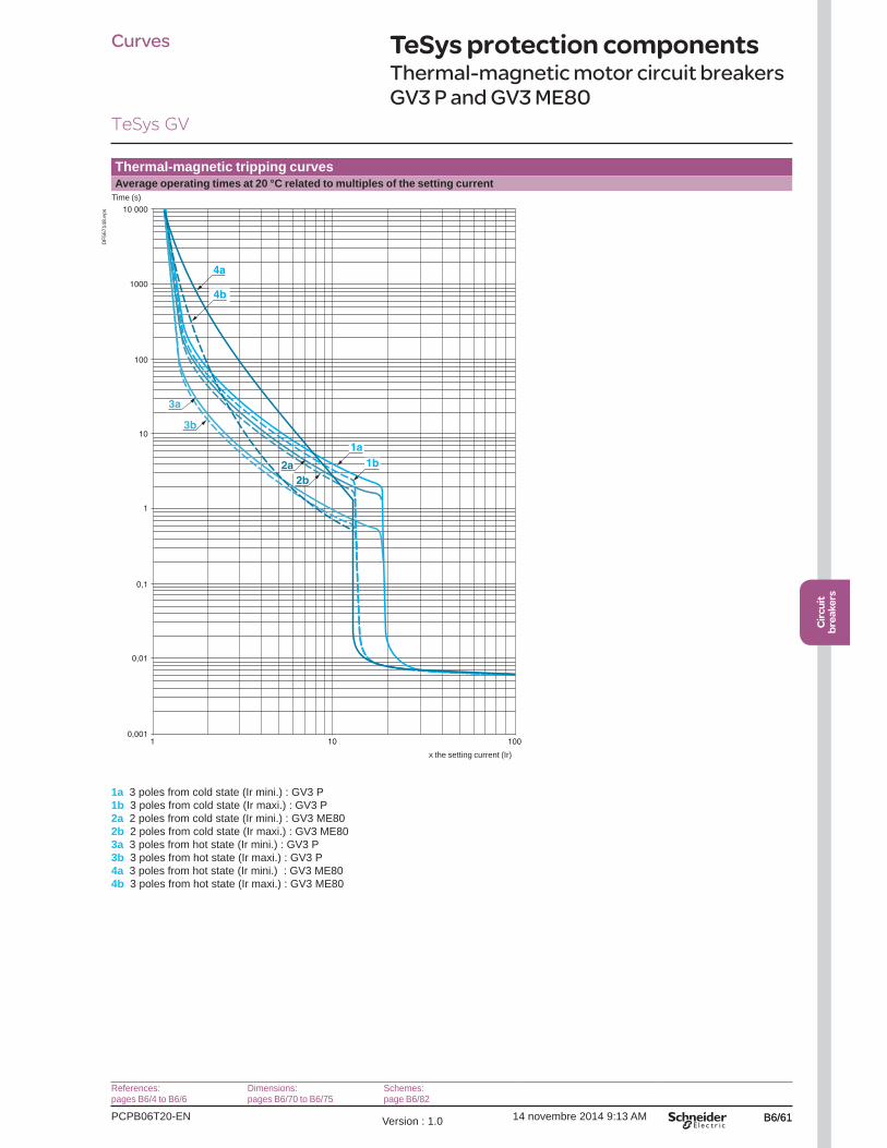
Thermal-magnetic tripping curvesAverage operating times at 20 °C related to multiples of the setting current
0,001
0,1
1
10
100
0,01
1 10 100
1000
10 000
1a1b2a
2b
3a
3b
4a
4b
Time (s)
x the setting current (Ir)
DF5
6714
8.ep
s
1a 3 poles from cold state (Ir mini.) : GV3 P1b 3 poles from cold state (Ir maxi.) : GV3 P2a 2 poles from cold state (Ir mini.) : GV3 ME802b 2 poles from cold state (Ir maxi.) : GV3 ME803a 3 poles from hot state (Ir mini.) : GV3 P3b 3 poles from hot state (Ir maxi.) : GV3 P4a 3 poles from hot state (Ir mini.) : GV3 ME804b 3 poles from hot state (Ir maxi.) : GV3 ME80
TeSys protection componentsThermal-magnetic motor circuit breakers GV3 P and GV3 ME80
References:pages B6/4 to B6/6
Dimensions:pages B6/70 to B6/75
Schemes:page B6/82

PCPB06T20-ENVersion : 1.0 14 novembre 2014 9:13 AM
TeSys GV
B6/62
Curves
Current limitation on short-circuit (3-phase 400/415 V)Dynamic stress
I peak = f (prospective Isc) at 1.05 Ue = 435 V
1 10 15 100
100
10
1
76
8
9
= 0.9
= 0.8
= 0.
7
= 0.5
= 0.3
= 0.
25
5
1
32 4
Limited peak current (kA)
Prospective Isc (kA)
DF5
1063
5.ep
s
1 Maximum peak current2 56 -80 A3 48 -65 A4 37 -50 A5 30 -40 A6 23 -32 A7 17 -25 A8 12 -18 A9 9 -13 A
TeSys protection componentsThermal-magnetic motor circuit breakers GV3 P and GV3 ME80
References:pages B6/4 to B6/6
Dimensions:pages B6/70 to B6/75
Schemes:page B6/82

PCPB06T20-EN Version : 1.0 14 novembre 2014 9:13 AM B6/63
Circ
uit
brea
kers
TeSys GV
B6/63
Curves
Maximum thermal limit on short-circuitThermal limit in kA2s in the magnetic operating zone
Sum of I2dt = f (prospective Isc) at 1.05 Ue = 435 V
100
1000
10
11 10 15 100
1
432
8
7
65
Sum of I2dt (kA2s)
Prospective Isc (kA)
DF5
1102
1.ep
s
1 56-80 A (GV3 ME80)2 48-65 A (GV3 P65)3 37-50 A (GV3 P50)4 30-40 A (GV3 P40)5 23-32 A (GV3 P32)6 17-25 A (GV3 P25)7 12-18 A (GV3 P18)8 9-13 A (GV3 P13)
TeSys protection componentsThermal-magnetic motor circuit breakers GV3 P and GV3 ME80
References:pages B6/4 to B6/6
Dimensions:pages B6/70 to B6/75
Schemes:page B6/82

PCPB06T20-ENVersion : 1.0 14 novembre 2014 9:13 AM
TeSys GV
B6/76
Dimensions, mounting
GV3 PDimensions
136
X1
X1
132
6864
55
DF5
6904
2.ep
s
9 18
(2)(1)
DF5
6904
3.ep
sX1 = Electrical clearance (ISC max) 40 mm for Ue y 500 V, 50 mm for Ue y 690 V
(1) Blocks GV ANpp , GV ADpp and GV AM11.(2) Blocks GV3 AUpp and GV3 ASpp.
Note: Leave a gap of 9 mm between 2 circuit breakers: either an empty space or side-mounting add-on contact blocks. Horizontal mounting is possible up to 40 °C.
MountingMounting with TeSys contactor LC1 D40A…D65A Side by side mounting with TeSys contactor LC1 D40A…D65A
(S-shape busbar system GV3 S)
231
120
136 55
DF5
6904
4.ep
s
136 119
138D
F569
045.
eps
Mounting on rail AM1 DE200 or AM1 ED201 Panel mounting, using M4 screws
6864
144
DF5
6900
4.ep
s
136 3xØ4
137,
5
37,5
DF5
6904
6.ep
s
Mounting on pre-slotted plate AM1 PA
136 18,7 18,7
137,
5
AF1 EA4
DF5
6900
5.ep
s
TeSys protection componentsThermal-magnetic motor circuit breakers GV3 P

PCPB06T20-EN Version : 1.0 14 novembre 2014 9:13 AM B6/77
Circ
uit
brea
kers
TeSys GV
B6/77
GV3 PBusbar systemsSet of busbars GV3 G264 Set of busbars GV3 G364
119
16
DF5
6904
7.ep
s 183
16
DF5
6904
8.ep
s
Note: Leave a space of 9 mm between 2 circuit breakers: either an empty space or side-mounting add-on contact blocks. Horizontal mounting is possible up to 40 °C.
MountingMounting of external operator GV3 APN01, GV3 APN02 or GV3 APN04 for motor circuit breakers GV3 P
0,5...443
60
a
60
6
= =
DB
1274
12.e
ps
Door cut-out
48= =
==
48
4Ø3,5 (1)16
16
Ø3,5
Ø22
DB
1266
34.e
ps
Mounting of external operator GV APH03 for motor circuit breakers GV3 P
0,5...4
43 b
60
6
213,
4
73,8
= =
DB
1274
13.e
ps
Door cut-out
(1) For IP65 only.
48= =
==
48
4Ø3,5 (1)16
16
Ø3,5
Ø22
DB
1266
34.e
ps
a bMini Maxi Mini Maxi
GV3 APNpp 189 300 - -GV3 APNpp + GV APK12 300 481GV3 APNpp + GV APH03 - - 200 300GV3 APNpp + GV APH03 + GV APK12
- - 300 492
Dimensions, mounting
TeSys protection componentsThermal-magnetic motor circuit breakers GV3 P
(1) For IP65 only.

PCPB06T20-ENVersion : 1.0 14 novembre 2014 9:13 AM
TeSys GV
B6/78
GV3 ME80Dimensions
17,3
22 77,5113
100…
110
120
5,5
X1
X1
45=
=
70
61,221,2
204,5
DF5
6902
0.ep
s
70,4
(1)
DF5
6902
1.ep
sX1 = Electrical clearance (ISC max) 40 mm for Ue y 500 V, 50 mm for Ue y 690 V
(1) Blocks GV3 A01…A07.
MountingMounting on rail AM1 DE200 or AM1 ED201 Panel mounting, using M4 screws Mounting on pre-slotted plate AM1 PA
122,5
DF5
6902
2.ep
s
113 ==
61,2
21,22020
100…
110
DF5
6902
3.ep
s
20113 AF1 EA4
100…
110
DF5
6902
4.ep
s
Dimensions, mounting
TeSys protection componentsThermal-magnetic motor circuit breakers GV3 ME80

PCPB06T20-ENVersion : 1.0 14 novembre 2014 9:13 AM
TeSys GV
B6/82
TeSys protection componentsThermal-magnetic motor circuit breakers GV2 ME, GV2 P, GV3 P and GV2 RT
Schemes
SchemesGV2 MEpp and GV2 RT GV2 Ppp GV3 Ppp
2/T1
4/T2
6/T3
1/L1
3/L2
5/L3
DF5
6906
7.ep
s
2/T1
4/T2
6/T3
1/L1
3/L2
5/L3
DF5
6906
8.ep
s
2/T1
4/T2
6/T3
1/L1
3/L2
5/L3
DF5
6906
8.ep
s
Front mounting add-on contact blocks Instantaneous auxiliary contacts
Front mounting add-on contact blocks Instantaneous auxiliary contacts and fault signalling contacts
GV AE1 GV AE11 GV AE20 GV AED101 GV AED011
1314 12
11
or
DF5
6906
9.ep
s
1314 22
21
DF5
6907
0.ep
s
1314
2324
DF5
6907
1.ep
s
9798
2324
DF5
6907
2.ep
s
9798
2122
DF5
6907
3.ep
s
Side mounting add-on contact blocks Instantaneous auxiliary contacts and fault signalling contactsGV AD0110 GV AD0101 GV AD1010 GV AD1001
535496
95
DF5
6907
4.ep
s
5251
9695
DF5
6907
5.ep
s
9798
5354
DF5
6907
6.ep
s
v
9798
5152
DF5
6907
7.ep
s
Instantaneous auxiliary contacts Short-circuit signalling contactsGV AN11 GV AN20 GV AM11
(62) 32
(61) 31 43 (73)
44 (74)DF5
6907
8.ep
s
(64) 34
(63) 33 43 (73)
44 (74)D
F569
079.
eps
050608
DF5
6908
0.ep
s
Voltage trips Current limiterGV AUppp GV ASppp GV AXppp GV1 L3
D1
D2
DF5
6908
1.ep
s
D1
D2
DF5
1101
2.ep
s
D1
D2
E1
E2
DF5
6908
3.ep
s
1/L1
3/L2
5/L3
DF5
6908
4.ep
s
Use of fault signalling contact and short-circuit signalling contact
Connection of undervoltage trip for dangerous machines (conforming to INRS) on GV2 ME only
GV AD10ppGV AM11
Short-circuit signalling
Trip signalling
N/C or N/O Start-Stop contact
DF5
6908
5.ep
s
2/T
1
4/T
2
6/T
3
1/L1
3/L2
5/L3
D1
D2
E2
E1
10Agl max
DF5
6908
6.ep
s

PCPB06T20-EN Version : 1.0 14 novembre 2014 9:13 AM B6/83
Circ
uit
brea
kers
TeSys GV
B6/83
Schemes TeSys protection componentsThermal-magnetic motor circuit breakers GV3 ME80 and GV7 R
SchemesMotor circuit breakers Auxiliary contact block modulesGV3 ME80 GV3 A01 GV3 A02 GV3 A03 GV3 A05 GV3 A06 GV3 A07
2/T1
4/T2
6/T3
1/L1
3/L2
5/L3
DF5
6908
7.ep
s 1314 22
21
DF5
6908
8.ep
s
1314
2324
DF5
6908
9.ep
s 1314
2324 32
31
DF5
6909
0.ep
s 1314
2324
3334
DF5
6909
1.ep
s 1314
2324
3334
DF5
6909
2.ep
s 2324 32
311314
DF5
6909
3.ep
s
Fault signalling contacts Voltage tripsGV3 A08 GV3 A09 GV3 B GV3 D
9695
DF5
6909
4.ep
s
9798D
F569
095.
eps D1
D2
U
DF5
6909
6.ep
s C1
C2
DF5
6909
7.ep
s
Motor circuit breakers Add-on auxiliary contacts according to their location (1)
GV7 R GV7 AE11, GV7 AB11
2/T1
4/T2
6/T3
1/L1
3/L2
5/L3
DF5
6909
8.ep
s
Location 1C/O contact
Location 2 Trip indication
Location 3 Electrical fault indication
Location 4 C/O contact
1114 12
DF5
6909
9.ep
s
9194 92
DF5
6910
0.ep
s
8184 82
DF5
6910
1.ep
s
2124 22
DF5
6910
2.ep
s
circuit-breaker to allow personalised marking according to the function of the contact or contacts.(1) See pages B6/91 and B6/17.
Electric tripsGV7 AUppp GV7 ASppp GV7 AD111, AD112
D1
D4D
F569
103.
eps
C1
C2D
F569
104.
eps
9897 50 ms
DF5
6910
5.ep
s
Recommended application schemes GV7 AD111, AD112Fault indication Contactor opening on overload
9897 50 ms
– KA1
2324
1314
– KA1
Reset
Overload fault
DF5
6910
6.ep
s
9897 50 ms
– KM1– KA1
A1
A2
A1
A2
B1
– KA1
2122
ResetDF5
6910
7.ep
s
Associated componentsKA1: CA2 KN or CAD N
Associated componentsKA1: CAD + LAD 6K10 or RHKKM1: LC1 D or LC1 F

PCPB06T30-EN Version : 1.0 14 novembre 2014 9:12 AM B6/89
Circ
uit
brea
kers
TeSys GV
B6/89
Characteristics
Type of contacts Instantaneous auxiliary GV AN, GV AD
Fault signalling GV AD, GV AM11 (1)
Instantaneous auxiliary GV AE
Rated insulation voltage (Ui) (associated insulation coordination)
Conforming to IEC 60947-1 V 690 690 250 (690 in relation to main circuit)
Conforming to CSA C22-2 n° 14 and UL 508
V 600 300 300
Conventional thermal current (Ith)
Conforming to IEC 60947-5-1 A 6 2.5 2.5
Conforming to CSA C22-2 n° 14 and UL 508
A 5 1 1
Mechanical durability (C.O.: Close - Open)
C.O. 100 000 1000 100 000
Operational power and current conforming to IEC 60947-5-1. a.c. operation
AC-15/100 000 C.O. AC-14/1000 C.O. AC-15/100 000 C.O.
Rated operational voltage (Ue)
V 48 110 127
230 240
380 415
440 500 690 24 48 110 127
230 240
24 48 110 127
230 240
Operational power, normal conditions
VA 300 500 720 850 650 500 400 36 48 72 72 48 60 120 120
Occasional breaking and making capacities, abnormal conditions
kVA 3 7 13 15 13 12 9 0.22 0.3 0.45 0.45 0.48 0.6 1.27 2.4
Rated operational current (Ie)
A 6 4.5 3.3 2.2 1.5 1 0.6 1.5 1 0.5 0.3 2 1.25 1 0.5
Operational power and current conforming to IEC 60947-5-1. d.c. operation
DC-13/100 000 C.O. DC-13/1000 C.O. DC-13/100 000 C.O.
Rated operational voltage (Ue)
V 24 48 60 110 240(2)
– – 24 48 60 – 24 48 60 –
Operational power, normal conditions
W 140 240 180 140 120 – – 24 15 9 – 24 15 9 –
Occasional breaking and making capacities, abnormal conditions
W 240 360 240 210 180 – – 100 50 50 – 100 50 50 –
Rated operational current (Ie)
A 6 5 3 1.3 0.5 – – 1 0.3 0.15 – 1 0.3 0.15 –
Low power switching reliability of contact GV AE: Number of failures for “n” million operating cycles (17 V-5 mA): = 10-6
Minimum operational conditions d.c. operation
V 17mA 5
Short-circuit protection By GB2 CBpp circuit breaker (rating according to operational current for Ue y 415 V) or by gG fuse 10 A max
GB2 CB06 or gG fuse 10 A max
Cabling, screw clamp terminals Number of conductors 1 2Solid cable mm2 1…2.5 1…2.5Flexible cable without cable end mm2 0.75…2.5 0.75…2.5Flexible cable with cable end mm2 0.75…1.5 0.75…1.5Tightening torque N.m 1.4 max 1.4 max
Cabling, spring terminal connections
GV AN onlyFlexible cable without cable end mm2 0.75…2.5 0.75…2.5 – 0.75…1.5
Operation of instantaneous auxiliary contactsGV3P, GV3L
0 1Power pole
GV AN20 FF
GV AN11 FO
GV AE1 FO
GV AE20 FF
GV AE11 FO
GV AD10pp FO
GV AED101 FGV AED011 O
GV20 1
Power pole
GV AN20 FF
GV AN11 FO
GV AE1 FO
GV AE20 FF
GV AE11 FO
GV AD10pp FGV AD11pp O
Contact open Contact Close
DB
4023
99.e
ps
Operation of fault signalling contacts
GV AM11Change of state following tripping on short-circuit.
GV AD10pp and GV AD01ppChange of state following tripping on short-circuit, overload or undervoltage.
(1) For application example of fault signalling contact and short-circuit signalling contact, see page B6/82.(2) Add an RC circuit type LA4 D to the load terminals, see page B8/17.
TeSys protection componentsThermal-magnetic motor circuit breakers GV2, GV3 P and GV3 LAuxiliary contacts
References:page B6/11
Dimensions, schemes:pages B6/38 to B6/48 and B6/70 to B6/83

PCPB06T30-ENVersion : 1.0 14 novembre 2014 9:12 AM
TeSys GV
B6/90
Characteristics
Type of contacts Instantaneous auxiliary contacts GV3 A01…A07
Fault signalling contacts GV3 A08 and A09
Rated insulation voltage (Ui) Conforming to IEC 60947-1 V 690 690
Conforming to CSA C22-2 n° 14, UL 508
V 600 (B600) 600 (B600)
Conventional rated thermal current (Ith)
Conforming to IEC 60947-5-1 A 6 6
Conforming to CSA C22-2 n° 14, UL 508
A 5 (B600) 5 (B600)
Mechanical durability (C.O.: Close - Open)
C.O. 100 000 1000
Operational power and current conforming to IEC 60947-5-1 a.c. operation
Rated operational voltage (Ue)
V 48 110 127
220 240
380 415
440 500 690 48 110 127
220 240
380 415
440 500 690
Operational power AC-11/100 000 C.O. AC-11/1000 C.O.
VA 350 500 800 850 700 700 400 240 460 800 850 450 450 200
Occasional breaking and making capacities
kVA 4 12 20 20 15 15 10 2.4 8 12 15 12 12 8
Operational current (Ie) A 6 4.5 3.5 2.2 1.5 1.5 0.6 5 3.6 3.5 2.2 1 1 0.3
Operational power and current conforming to IEC 60947-5-1 d.c. operation
Rated operational voltage (Ue)
V 24 48 60 110 220 24 48 60 110 220
Operational power DC-11/100 000 C.O. DC-11/1000 C.O.
W 180 240 180 140 120 120 120 90 70 60
Occasional breaking and making capacities
W 240 360 240 210 180 180 180 135 105 90
Operational current (Ie) A 6 5 3 1.3 0.5 5 2.5 1.5 0.7 0.3
Short-circuit protection By GB2 CB08 circuit breaker or gG fuse, 6A max
Connection Number of conductors 1 2
Solid cable mm2 1…2.5 1…2.5
Flexible cable without cable end mm2 0.75…2.5 0.75…2.5
Flexible cable with cable end mm2 0.75…2.5 0.75…1.5
Contact operation GV3
0 1Power pole
GV3 A01, A07 OF
GV3 A02 FF
GV3 A03 OFF
GV3 A05 FFF
GV3 A06 FO
Contact open Contact Close
DB
4024
00.e
ps GV3 A08 and A09 change state following tripping on short-circuit or overload
TeSys protection componentsThermal-magnetic motor circuit breakers GV3 ME80Auxiliary contacts
References:page B6/11
Schemes:page B6/48

PCPB06T30-EN Version : 1.0 14 novembre 2014 9:12 AM B6/93
Circ
uit
brea
kers
TeSys GV
B6/93
Characteristics
Characteristics of electric tripsCircuit breaker type GV2 ME, GV2 P
GV3 P, GV3 LGV2 ME only
GV3 ME80 GV7 R
Type of trip GV AU GV AS GV AX (1) GV3 B GV3 D GV7 AU GV7 ASRated insulation voltage (Ui) Conforming to IEC 60947-1 V 690 690 500 690 690 690 690
Conforming to CSA C22-2 n° 14, UL 508
V 600 600 – 600 (B600) 600 (B600) 600 600
Operational voltage Conforming to IEC 60947-1 V 0.85… 1.1 Un
0.7… 1.1 Un
0.85… 1.1 Un
0.8…1.1 Un 0.85… 1.1 Un
0.7… 1.1 Un
Drop-out voltage V 0.7… 0.35 Un
0.75… 0.2 Un
0.7… 0.35 Un
0.7…0.35 Un 0.35… 0.7 Ue
0.2… 0.75 Ue
Inrush consumption a VA 12 14 12 12 < 10
c W 8 10.5 8 7 < 5
Sealed consumption a VA 3.5 5 3.5 7 < 5
c W 1.1 1.6 1.1 2.5 < 5
Operating time Conforming to IEC 60947-1 From the moment the voltage reaches its operational value until opening of the circuit-breaker.
ms 10…15 10 15 < 50
On-load factor 100 % 100 % 100 %
Cabling Number of conductors 2 or 4 1 or 2 1
Solid cable mm2 1…2.5 1…2.5 1.5
Flexible cable without cable end mm2 0.75…2.5 0.75…2.5 1.5
Flexible cable with cable end mm2 0.75…1.5 0.75…2.5 1
Tightening torque N.m 1.4 max 1.2 1.2
Mechanical durability (C.O.: Close - Open)
C.O. 30 000 (GV2 ME and GV2 P) 10 000 (GV3 P and GV3 L)
50 % of the mechanical durability of the circuit-breaker
(1) Wiring scheme of undervoltage trip for dangerous machines (conforming to INRS) on GV2 ME only, see page B6/82.
TeSys protection componentsThermal-magnetic motor circuit breakersElectric trips
References:page B6/23
Schemes:pages B6/82 to B6/83
PCPB06T30-ENVersion : 1.0 14 novembre 2014 9:12 AM
TeSys GV
B6/94
Characteristics
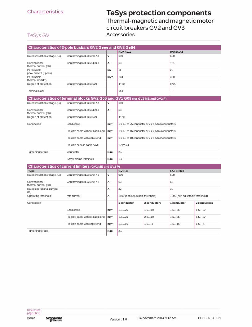
Characteristics of 3-pole busbars GV2 Gppp and GV3 Gp64GV2 Gppp GV3 Gp64
Rated insulation voltage (Ui) Conforming to IEC 60947-1 V 690 690
Conventional thermal current (Ith)
Conforming to IEC 60439-1 A 63 115
Permissible peak current (I peak)
kA 11 20
Permissible thermal limit (I2t)
kA2s 104 300
Degree of protection Conforming to IEC 60529 IP 20 IP 20
Terminal block Yes –
Characteristics of terminal blocks GV2 G05 and GV1 G09 (for GV2 ME and GV2 P)Rated insulation voltage (Ui) Conforming to IEC 60947-1 V 690
Conventional thermal current (Ith)
Conforming to IEC 60439-1 A 63
Degree of protection Conforming to IEC 60529 IP 20
Connection Solid cable mm2 1 x 1.5 to 25 conductor or 2 x 1.5 to 6 conductors
Flexible cable without cable end mm2 1 x 1.5 to 16 conductor or 2 x 2.5 to 4 conductors
Flexible cable with cable end mm2 1 x 1.5 to 10 conductor or 2 x 1.5 to 2 conductors
Flexible or solid cable AWG 1 AWG 4
Tightening torque Connector N.m 2.2
Screw clamp terminals N.m 1.7
Characteristics of current limiters (GV2 ME and GV2 P)Type GV1 L3 LA9 LB920
Rated insulation voltage (Ui) Conforming to IEC 60947-1 V 690 690
Conventional thermal current (Ith)
Conforming to IEC 60947-1 A 63 63
Rated operational current(Ie)
A 32 32
Operating threshold rms current A 1500 (non adjustable threshold) 1000 (non adjustable threshold)
Connection 1 conductor 2 conductors 1 conductor 2 conductors
Solid cable mm2 1.5…25 1.5…10 1.5…25 1.5…10
Flexible cable without cable end mm2 1.5…25 2.5…10 1.5…25 1.5…10
Flexible cable with cable end mm2 1.5…16 1.5… 4 1.5…16 1.5… 4
Tightening torque N.m 2.2
TeSys protection componentsThermal-magnetic and magnetic motor circuit breakers GV2 and GV3Accessories
References:page B6/13