Embed Size (px)
DESCRIPTION
control engineering
Citation preview


Automation DirectC-More + DirectLogic DL05
6” Reduced Features Touch Panel
270 Nits TFT, 50000 Hrs @ 25°C, Reduced at High Temp.
None
16 DC In 10 Relay Out 2-3 Amp contacts
Very basic PLC
2 inputs can accept 5 KHz Signals
Seperate HMI, PLC and cables increase panel space by 40%
$540 (HMI) + $186 (PLC &
Cbl.) = $726
All Product names, trademarks and registered trademarks are the property of their respective manufacturers or legal holders. EZAutomation disclaims any pro-prietary interest in the marks or names of others. All prices are US List prices and are subject to change without notice. All competitors’ prices and features are from their online stores or publications or from tests conducted by EZAutomation.
Similar savings for all size HMIs
up to 15”, & PLCs to 256 I/O
EZTouchPLCTM Superior Operator
Interface (HMI) with Free PLC,
All-in-One
Free Application Support 6:00 AM to midnight CST,
weekends 9:00 AM to 5:00 PM CST
EZAutomation6” EZTouchPLCTM
6” White LED Touch Panel
400 Nits White LED TFT Display, 75000 Hrs @ 55°C
Stored in USB, Remotely accessible thru Modem
16 DC In 8 Relay Out with NO/NC 10 Amp contacts
High-end PLC with Advanced Math
2 inputs can be configured to accept 20 KHz signals
Integrated All-in-One HMI and PLC reduces panel space by 40%
$549
6” HMI & 24 I/O PLCAll-in-One

www.controleng.com

the #1 value in automationOrder Today, Ships Today!
* See our Web site for details and restrictions. © Copyright 2013 AutomationDirect, Cumming, GA USA. All rights reserved. 1-800-633-0405
The new ViewMarq LED message boards can display preformatted and real-time factory fl oor data messages sent by a PLC, PC, or other master device. The text message displays can be controlled by:
• ASCII strings through the RS232 or RS485 port • Modbus RTU messsages through the RS232 or RS485 port• Modbus TCP messages through the Ethernet port
The Viewmarq line off ers:
• One-, two-, and four-line displays• Viewing distances up to 400 feet and 140 degree viewing angle• (1) RS232, (1) RS485 and (1) Ethernet port standard on all models• Scrolling, blinking capability• NEMA 4 / NEMA 12 extruded aluminum housings suitable for harsh environments
Use the FREE Viewmarq confi guration software(online download) to confi gure the display; create,preview and send messages from a PC; or createASCII strings that can be transferred to PLC instructionsto control the Viewmarq.
with Viewmarq industrial displaysGET YOUR MESSAGE ACROSS
Research, price, buy at:www.automationdirect.com/viewmarq
Industrial LED messagedisplays keep your plantpersonnel in the know
Six models to choose from:
$499$799
$1,199
$759$1,099
$1,900
PRICES
®
Built-in Ethernet {all models}
input #1 at www.controleng.com/information

800-972-ASCO (2726) | www.ascovalve.com/today | e-mail: [email protected]
While other suppliers struggle with longer lead times and broken supply chains — delivering fewer and fewer products in a timely manner — ASCO leads the industry in express shipping performance. Together, our ASCO Today and ASCO 5Day programs cover more than 40,000 products: the industry’s widest range of solenoid valves and other fluid control offerings available for rapid shipment. In fact, if you order online by 3:00 pm EST, many popular products ship the same day. Get guaranteed shipment with ASCO Today and 5Day. Right. Now.
ASCO Today. Onsite, on time. Right. Now.
I need guarantees,not promises.Send what I need,when I need it.
Or don’t bother.
Scan this QR Code*to learn more about theASCO Today and 5Day programs.
* Requires QR Code reader
The ASCO trademark is registered in the U.S. and other countries. FasN is a trademark of ASCO Valve, Inc. The Emerson logo is a trademark and service mark of Emerson Electric Co. © 2013 ASCO Valve, Inc.
input #2 at www.controleng.com/information

30
34
26
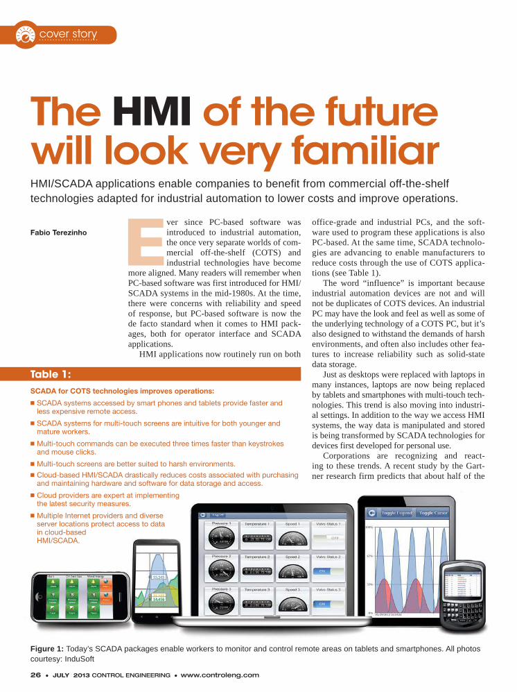
26 The HMI of the future will look very familiar HMI/SCADA applications enable companies to bene� t from commercial off-the-shelf technologies adapted for industrial automation to lower costs and improve operations.
30 Reducing peak demand as electrical consumption patterns change Proliferation of electric vehicles and other rechargeable devices can create new peak demand patterns. Planning and renewable sources can mitigate the effects.
34 Service offerings expand from automation distributors Today’s distributors offer more than warehouses full of the latest gadgets, providing a diversity of services to ease buying, installation, start-up, and more.
FeaturesCourtesy: InduSoft
2 ● JULY 2013 CONTROL ENGINEERING ● www.controleng.com
CONTROL ENGINEERING (ISSN 0010-8049, Vol. 60, No. 7, GST #123397457) is published 12x per year, Monthly by CFE Media, LLC, 1111 W. 22nd Street, Suite #250, Oak Brook, IL 60523. Jim Langhenry, Group Publisher /Co-Founder; Steve Rourke CEO/COO/Co-Founder. CONTROL ENGINEERING copyright 2013 by CFE Media, LLC. All rights reserved. CONTROL ENGINEERING is a registered trademark of CFE Media, LLC used under license. Peri-odicals postage paid at Oak Brook, IL 60523 and additional mailing offices. Circulation records are maintained at CFE Media, LLC, 1111 W. 22nd Street, Suite #250, Oak Brook, IL 60523. Telephone: 630/571-4070 x2220. E-mail: [email protected]. Postmaster: send address changes to CONTROL ENGINEERING, 1111 W. 22nd Street, Suite #250, Oak Brook, IL 60523. Publications Mail Agreement No. 40685520. Return undeliverable Canadian addresses to: 1111 W. 22nd Street, Suite #250, Oak Brook, IL 60523. Email: [email protected]. Rates for nonqualified subscriptions, including all issues: USA, $ 145/yr; Canada, $ 180/yr (includes 7% GST, GST#123397457); Mexico, $ 172/yr; International air delivery $318/yr. Except for special issues where price changes are indicated, single copies are available for $20.00 US and $25.00 foreign. Please address all subscription mail to CONTROL ENGINEERING, 1111 W. 22nd Street, Suite #250, Oak Brook, IL 60523. Printed in the USA. CFE Media, LLC does not assume and hereby disclaims any liability to any person for any loss or damage caused by errors or omissions in the material contained herein, regardless of whether such errors result from negligence, accident or any other cause whatsoever.
®
Vol. 60Number 7
COVERING CONTROL, INSTRUMENTATION, AND AUTOMATION SYSTEMS WORLDWIDE
JULY 2013
input #3 at www.controleng.com/information
To learn more, read the complete application story at www.us.profi net.com.Or, simply scan the QR code.
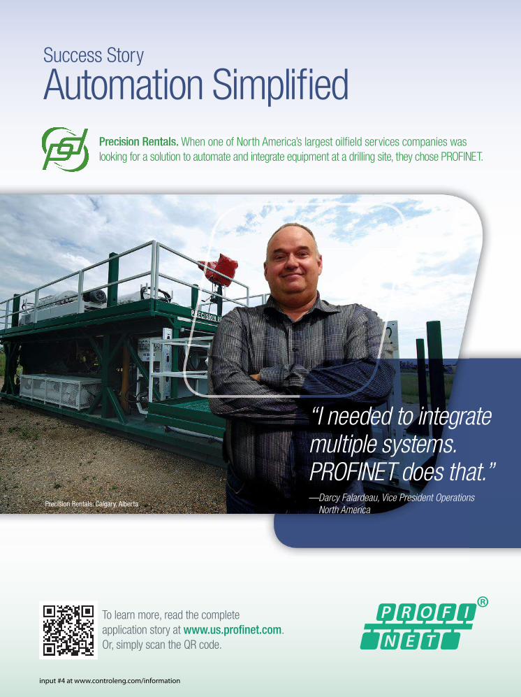
Success Story
Automation Simplifi ed
“I needed to integratemultiple systems. PROFINET does that.”— Darcy Falardeau, Vice President Operations
North America
Precision Rentals. When one of North America’s largest oilfi eld services companies was looking for a solution to automate and integrate equipment at a drilling site, they chose PROFINET.
Precision Rentals: Calgary, Alberta
input #4 at www.controleng.com/information
www.controleng.com ● CONTROL ENGINEERING JULY 2013 ● 5
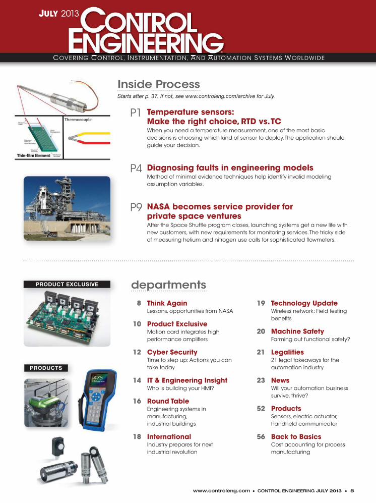
8 Think Again Lessons, opportunities from NASA
10 Product Exclusive Motion card integrates high performance ampli� ers
12 Cyber Security Time to step up: Actions you can take today
14 IT & Engineering Insight Who is building your HMI?
16 Round Table Engineering systems in manufacturing, industrial buildings
18 International Industry prepares for next industrial revolution
departments
Inside ProcessStarts after p. 37. If not, see www.controleng.com/archive for July.
P1 Temperature sensors: Make the right choice, RTD vs. TC When you need a temperature measurement, one of the most basic decisions is choosing which kind of sensor to deploy. The application should guide your decision.
P4 Diagnosing faults in engineering models Method of minimal evidence techniques help identify invalid modeling assumption variables.
P9 NASA becomes service provider for private space ventures After the Space Shuttle program closes, launching systems get a new life with new customers, with new requirements for monitoring services. The tricky side of measuring helium and nitrogen use calls for sophisticated � owmeters.
PRODUCT EXCLUSIVE
PRODUCTS
COVERING CONTROL, INSTRUMENTATION, AND AUTOMATION SYSTEMS WORLDWIDEOVERING CONTROL, INSTRUMENTATION, AND AUTOMATION ®
JULY 2013
19 Technology Update Wireless network: Field testing bene� ts
20 Machine Safety Farming out functional safety?
21 Legalities 21 legal takeaways for the automation industry
23 News Will your automation business survive, thrive?
52 Products Sensors, electric actuator, handheld communicator
56 Back to Basics Cost accounting for process manufacturing
6 ● JULY 2013 CONTROL ENGINEERING ● www.controleng.com
More learning, less sur� ngExclusive blogs at www.controleng.com/blogs� Real World Engineering: Moving virtual machines into your workplace� Machine Safety: NRTL certi� ed convergence of machine control and the safety-related parts� Pillar to Post: Explaining IP67 to people who’ve never heard of it
Join the discussions at www.linkedin.com/groups?gid=1967039 � RS422 vs. RS485 for point to multi-point communication� What are the best conventions for naming � eld devices? What information can we include?� If you have the option to choose, how do you select PLC language?� Wiring strategy for safety loops: How can we make sure we achieve SIL3?
Topic-speci� c e-newslettersStart your subscriptions at www.controleng.com/newsletters� Weekly News: Understanding the smart grid and its supporting standards� Information Control: Cyber security webcast now available on-demand� Safety & Security: Is your controller tough enough?� Process & Advanced Control: Managing process safety with � exible I/O
www.controleng.com/media-library
� Videos and Webcasts on demand
� Online training center
� Engineering education center
� Case studies—130+ all in one place on dozens of topics
� Useful white papers on many topics
www.facebook.com/ ControlEngineeringMagazine
www.linkedin.com/ groups?gid=1967039
www.twitter.com/controlengtips
http://tinyurl.com/CEgoogleplus
Connect with us!
Media library
Services available
Channels New Products Media Library Connect Industry News Events, Awards Newsletters Blogs Magazine
JULY www.controleng.com
� Channels and new product areasVisit our specialized microsites providing feature articles, news, products, applica-tions, tutorials, research, and more gath-ered for engineering professionals.
� New site search engineFind content from Control Engineering magazines from 1997 to the present.
� e-NewslettersKeep current with the latest informationand news with electronic newsletters.
� System Integrator GuideConsult our listing of more than 2,300 au-tomation system integrators. You can � nd a speci� c company or run a seven-way multi-parameter search.
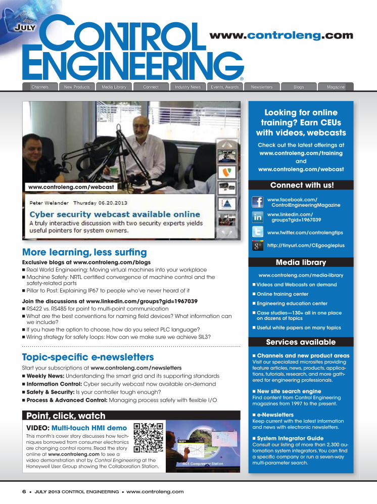
Looking for onlinetraining? Earn CEUs
with videos, webcastsCheck out the latest offerings atwww.controleng.com/training
andwww.controleng.com/webcast
Point, click, watch VIDEO: Multi-touch HMI demoThis month’s cover story discusses how tech-niques borrowed from consumer electronics are changing control rooms. Read the story online at www.controleng.com to see a video demonstration shot by Control Engineering at the Honeywell User Group showing the Collaboration Station.
www.controleng.com/webcast
800 453 6202
input #5 at www.controleng.com/information
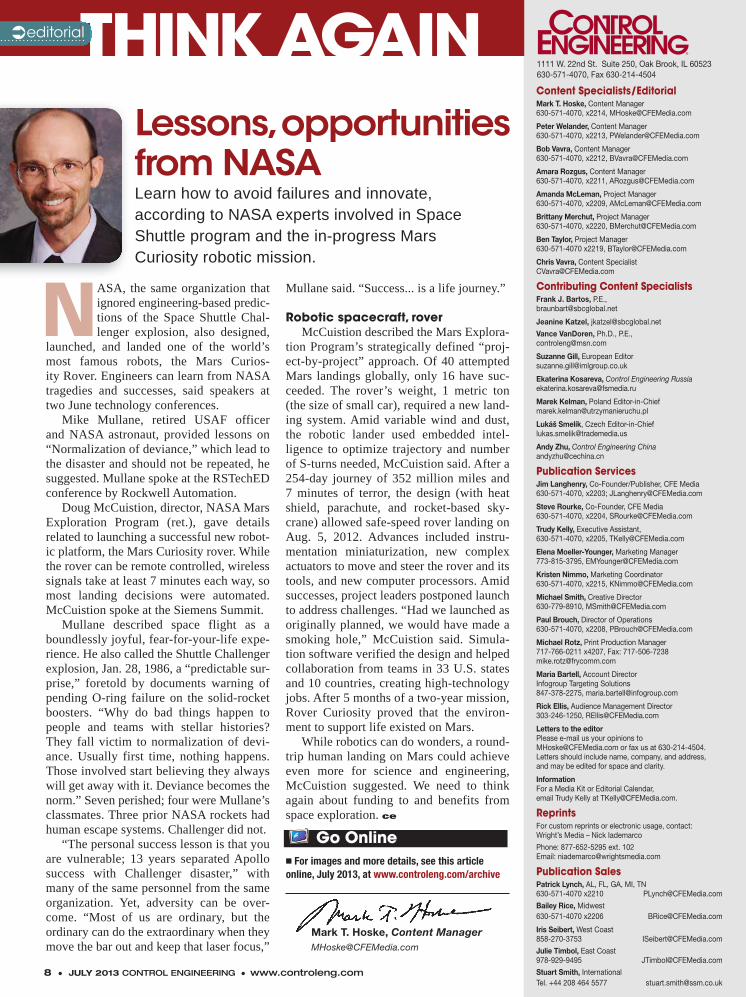
NASA, the same organization that ignored engineering-based predic-tions of the Space Shuttle Chal-lenger explosion, also designed,
launched, and landed one of the world’s most famous robots, the Mars Curios-ity Rover. Engineers can learn from NASA tragedies and successes, said speakers at two June technology conferences.
Mike Mullane, retired USAF officer and NASA astronaut, provided lessons on “Normalization of deviance,” which lead to the disaster and should not be repeated, he suggested. Mullane spoke at the RSTechED conference by Rockwell Automation.
Doug McCuistion, director, NASA Mars Exploration Program (ret.), gave details related to launching a successful new robot-ic platform, the Mars Curiosity rover. While the rover can be remote controlled, wireless signals take at least 7 minutes each way, so most landing decisions were automated. McCuistion spoke at the Siemens Summit.
Mullane described space flight as a boundlessly joyful, fear-for-your-life expe-rience. He also called the Shuttle Challenger explosion, Jan. 28, 1986, a “predictable sur-prise,” foretold by documents warning of pending O-ring failure on the solid-rocket boosters. “Why do bad things happen to people and teams with stellar histories? They fall victim to normalization of devi-ance. Usually first time, nothing happens. Those involved start believing they always will get away with it. Deviance becomes the norm.” Seven perished; four were Mullane’s classmates. Three prior NASA rockets had human escape systems. Challenger did not.
“The personal success lesson is that you are vulnerable; 13 years separated Apollo success with Challenger disaster,” with many of the same personnel from the same organization. Yet, adversity can be over-come. “Most of us are ordinary, but the ordinary can do the extraordinary when they move the bar out and keep that laser focus,”
Mullane said. “Success... is a life journey.”
Robotic spacecraft, roverMcCuistion described the Mars Explora-
tion Program’s strategically defined “proj-ect-by-project” approach. Of 40 attempted Mars landings globally, only 16 have suc-ceeded. The rover’s weight, 1 metric ton (the size of small car), required a new land-ing system. Amid variable wind and dust, the robotic lander used embedded intel-ligence to optimize trajectory and number of S-turns needed, McCuistion said. After a 254-day journey of 352 million miles and 7 minutes of terror, the design (with heat shield, parachute, and rocket-based sky-crane) allowed safe-speed rover landing on Aug. 5, 2012. Advances included instru-mentation miniaturization, new complex actuators to move and steer the rover and its tools, and new computer processors. Amid successes, project leaders postponed launch to address challenges. “Had we launched as originally planned, we would have made a smoking hole,” McCuistion said. Simula-tion software verified the design and helped collaboration from teams in 33 U.S. states and 10 countries, creating high-technology jobs. After 5 months of a two-year mission, Rover Curiosity proved that the environ-ment to support life existed on Mars.
While robotics can do wonders, a round-trip human landing on Mars could achieve even more for science and engineering, McCuistion suggested. We need to think again about funding to and benefits from space exploration. ce
Content Specialists/EditorialMark T. Hoske, Content Manager630-571-4070, x2214, [email protected]
Peter Welander, Content Manager630-571-4070, x2213, [email protected]
Bob Vavra, Content Manager630-571-4070, x2212, [email protected]
Amara Rozgus, Content Manager630-571-4070, x2211, [email protected]
Amanda McLeman, Project Manager630-571-4070, x2209, [email protected]
Chris Vavra, Content Specialist630-571-4070, x2219, [email protected]
Brittany Merchut, Content Specialist630-571-4070, x2220, [email protected]
Ben Taylor, Project Manager630-571-4070 x2219, [email protected]
Contributing Content SpecialistsFrank J. Bartos, P.E., [email protected]
Jeanine Katzel [email protected]
Vance VanDoren Ph.D., P.E., [email protected]
Suzanne Gill, European [email protected]
Ekaterina Kosareva, Control Engineering [email protected]
Marek Kelman, Poland [email protected]
Lukáš Smelík, Czech [email protected]
Andy Zhu, Control Engineering [email protected]
Publication ServicesJim Langhenry, Co-Founder/Publisher, CFE Media630-571-4070, x2203; [email protected]
Steve Rourke, Co-Founder, CFE Media630-571-4070, x2204, [email protected]
Trudy Kelly, Executive Assistant,630-571-4070, x2205, [email protected]
Elena Moeller-Younger, Marketing Manager630-571-4070, x2215; [email protected]
Michael Smith, Creative Director630-779-8910, [email protected]
Paul Brouch, Web Production Manager630-571-4070, x2208, [email protected]
Michael Rotz, Print Production Manager717-766-0211 x4207, Fax: [email protected]
Maria Bartell, Account DirectorInfogroup Targeting Solutions847-378-2275, [email protected]
Rick Ellis, Audience Management DirectorPhone: 303-246-1250; [email protected]
Letters to the editor Please e-mail us your opinions [email protected] or fax us at 630-214-4504. Letters should include name, company, and address,and may be edited for space and clarity.
InformationFor a Media Kit or Editorial Calendar, email Trudy Kelly at [email protected].
ReprintsFor custom reprints or electronic usage, contact: Wright’s Media – Nick Iademarco
Phone: 877-652-5295 ext. 102Email: [email protected]
Publication SalesPatrick Lynch, AL, FL, GA, MI, TN630-571-4070 x2210 [email protected]
Bailey Rice, Midwest630-571-4070 x2206 [email protected]
Iris Seibert, West Coast858-270-3753 [email protected]
Julie Timbol, East Coast978-929-9495 [email protected]
Stuart Smith, InternationalTel. +44 208 464 5577 [email protected]
8 ● JULY 2013 CONTROL ENGINEERING ● www.controleng.com
THINK AGAINTHINK AGAINeditorial
Mark T. Hoske, Content [email protected]
1111 W. 22nd St. Suite 250, Oak Brook, IL 60523630-571-4070, Fax 630-214-4504
� For images and more details, see this article online, July 2013, at www.controleng.com/archive
Go Online
Lessons, opportunities from NASALearn how to avoid failures and innovate,according to NASA experts involved in Space Shuttle program and the in-progress MarsCuriosity robotic mission.
Content Specialists/EditorialMark T. Hoske, Content Manager630-571-4070, x2214, [email protected]
Peter Welander, Content Manager630-571-4070, x2213, [email protected]
Bob Vavra, Content Manager630-571-4070, x2212, [email protected]
Amara Rozgus, Content Manager630-571-4070, x2211, [email protected]
Amanda McLeman, Project Manager630-571-4070, x2209, [email protected]
Brittany Merchut, Project Manager630-571-4070, x2220, [email protected]
Ben Taylor, Project Manager630-571-4070 x2219, [email protected]
Chris Vavra, Content [email protected]
Contributing Content SpecialistsFrank J. Bartos, P.E., [email protected]
Jeanine Katzel, [email protected]
Vance VanDoren, Ph.D., P.E., [email protected]
Suzanne Gill, European [email protected]
Ekaterina Kosareva, Control Engineering [email protected]
Marek Kelman, Poland [email protected]
Lukáš Smelík, Czech [email protected]
Andy Zhu, Control Engineering [email protected]
Publication ServicesJim Langhenry, Co-Founder/Publisher, CFE Media630-571-4070, x2203; [email protected]
Steve Rourke, Co-Founder, CFE Media630-571-4070, x2204, [email protected]
Trudy Kelly, Executive Assistant,630-571-4070, x2205, [email protected]
Elena Moeller-Younger, Marketing Manager773-815-3795, [email protected]
Kristen Nimmo, Marketing Coordinator630-571-4070, x2215, [email protected]
Michael Smith, Creative Director630-779-8910, [email protected]
Paul Brouch, Director of Operations630-571-4070, x2208, [email protected]
Michael Rotz, Print Production Manager717-766-0211 x4207, Fax: [email protected]
Maria Bartell, Account DirectorInfogroup Targeting Solutions847-378-2275, [email protected]
Rick Ellis, Audience Management Director303-246-1250, [email protected]
Letters to the editor Please e-mail us your opinions [email protected] or fax us at 630-214-4504. Letters should include name, company, and address,and may be edited for space and clarity.
InformationFor a Media Kit or Editorial Calendar, email Trudy Kelly at [email protected].
ReprintsFor custom reprints or electronic usage, contact: Wright’s Media – Nick Iademarco
Phone: 877-652-5295 ext. 102Email: [email protected]
Publication SalesPatrick Lynch, AL, FL, GA, MI, TN630-571-4070 x2210 [email protected]
Bailey Rice, Midwest630-571-4070 x2206 [email protected]
Iris Seibert, West Coast858-270-3753 [email protected]
Julie Timbol, East Coast978-929-9495 [email protected]
Stuart Smith, InternationalTel. +44 208 464 5577 [email protected]

Pumped Up
• Unmatched Quality
• Superior Reliability
• Global Sales and Support
• American Made Since 1920
Whether you’re an OEM pump manufacturer, a pump assembler or a maintenance and repair professional, there’s a Baldor•Reliance® motor designed and manufactured for your specific motor-driven pump system application.
With Baldor•Reliance medium voltage horsepower ratings to 15,000 in single or three phase designs including explosion-proof, close-coupled, vertical P-base, submersible and immersible, no other motor manufacturer offers more choices, quality or pumped up reliability than Baldor. baldor.com 479-646-4711
©2013 Baldor Electric Company
input #6 at www.controleng.com/information
input #7 at www.controleng.com/information
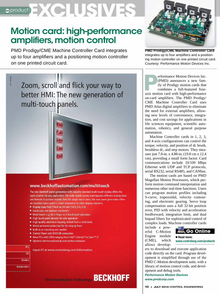
Performance Motion Devices Inc. (PMD) announces a new fam-ily of Prodigy motion cards that combines a full-featured four-
axis motion card with high-performance on-card amplifiers. The PMD Prodigy/CME Machine Controller Card uses PMD Atlas digital amplifiers to eliminate the need for external amplifiers, allow-ing new levels of convenience, integra-tion, and cost savings for applications in life sciences equipment, scientific auto-mation, robotics, and general purpose automation.
Machine Controller cards in 1, 2, 3, and 4-axis configurations can control the torque, velocity, and position of dc brush, brushless dc, and step motors. They mea-sure just 7.8-in. x 4.88-in. (19.8 cm x 12.4 cm), providing a small form factor. Card communications include 10/100 Mbps Ethernet with UDP and TCP protocols, serial RS232, serial RS485, and CANbus.
The motion cards are based on PMD Magellan Motion Processors, which per-form motion command interpretation and numerous other real-time functions. Users can program motion profiles including S-curve, trapezoidal, velocity contour-ing, and electronic gearing. Servo loop compensation uses a full 32-bit position error, PID with velocity and acceleration feedforward, integration limit, and dual biquad filters for sophisticated control of complex loads. Machine controller cards include a pow-erful C-Motion Engine module (CME), which allows develop-ers to download and execute application code directly on the card. Program devel-opment is simplified through use of the PMD C-Motion development suite, with a library of motion control code, and devel-opment and debug tools. Performance Motion Deviceswww.pmdcorp.com
Motion card: high-performance amplifiers, motion controlPMD Prodigy/CME Machine Controller Card integratesup to four amplifiers and a positioning motion controlleron one printed circuit card.
� Read more: www.controleng.com/products
Go Online
EXCLUSIVESEXCLUSIVESproduct
10 ● JULY 2013 CONTROL ENGINEERING
PMD Prodigy/CME Machine Controller Card integrates up to four amplifiers and a position-ing motion controller on one printed circuit card. Courtesy: Performance Motion Devices Inc.
PMD Prodigy/CME Machine Controller Card

input #8 at www.controleng.com/information
12 ● JULY 2013 CONTROL ENGINEERING ● www.controleng.com
Control systems represent a high-value target and are under attack. How bad is the risk? A recent survey conducted by Control Engineering indicated that
most respondents recognize that the risk is high to severe. Increasing international tensions are driving threat actors worldwide. A recent vendor briefing highlighted how vulnerable industrial cyber assets and their communications protocols truly are. The vulnerabilities transcend product lines within vendors and across vendors. The situation is improving in some areas, but most industrial control system (ICS) product suppli-ers and integrators do not have a security process within their software development and system integration lifecycle, or are early in their efforts.
So if you know there is risk, what can you do? You have to know what you have, build walls, monitor, and respond to threat indicators.
Step one, which you can begin today, is cre-ate an inventory of your control system assets. This includes all personnel and skills, controller hardware, networking hardware, communication channels, and operational procedures. Step two, take a look into any regulations impacting your cyber, physical, and operational security require-ments. If you do not have any (yet), then consid-er yourself lucky; it will be up to you to justify a cash outlay for security to your management. However, if you are in the energy or water sec-tors, several cyber security controls are already impacting you or will be soon.
Once you compile your initial inventories, the next steps are:
1. Create a baseline of security needs throughout your organization and its stakehold-ers. This is a key ingredient, as your organiza-tion will most likely have to create new roles and responsibilities to address ongoing threats.
2. Using your inventory of cyber assets, identify which are required for direct control functions. Then, identify what communication channels, applications, and services are required for each ICS cyber asset to perform its opera-tions. This process will not be easy, and your
control system vendors and integrators may not have specific answers for your environment.
3. Remove all other communication channels, applications, and services not necessary for nor-mal and emergency operating conditions.
4. Review the remaining communication channels, applications, and services for vulner-abilities. Using the inventory of firmware, appli-cations, and protocol versions, check them for out-of-date and/or vulnerable components.
5. Identify mitigating controls such as a network intrusion detection system (IDS), con-figured with specific rule sets for your control system protocols and communication channels, and not generic rules from IT environments.
6. Inventory your current operational proce-dures used by personnel to maintain the cyber assets and control system communication chan-nels. Review the procedures for vulnerabilities, and modify them as necessary.
This is only a start. There are proven IT defensive techniques, but often ICS devices are still vulnerable because many vendors do not have a security process within their software development lifecycle.
Therefore, the first step is for you, the asset owner and operator, to learn about what you have, what you need, and how to protect your networks with walls and limited trusts. It is also up to you to request a cyber, physical, and operational vulnerability assessment for all new implementations, including how any new device is coupled to your existing infrastructure. It is then up to you to take the necessary precautions to limit and monitor physical, cyber, and opera-tional interactions with your control environ-ment. For example, a laptop used by a technician should not be categorized as a tool since it may become compromised if not properly handled. This ideology has to transcend all aspects of your ICS environment. The cultural change and new responsibilities required are necessary but will not be an easy shift. ce
Matt Luallen is founder of Cybati, a security training and consulting organization.
SECURITYSECURITYcyber
Time to step up:Actions you can take today
‘Create an inventory of your control system
assets. This includes all personnel and skills, controller
hardware, networking hardware,
communication channels, and operational
procedures.’
Your control system cyber assets were not coded with security in mind, so you haveto build defenses yourself, always thinking about your complete security posture.Here are ways to start now.
� https://cybati.org/
� http://www.controleng.com/media-library/webcast-archive.html
� https://www.sans.org/webcasts/industrial-control-systems-security-briefing-live-houston-tx-96727?ref=131632
Go Online
Matt LuallenCybati

Visit alliedelec.com/control through Aug. 31 for your chance to win some top prizes.
Allied stocks all the top brands under one roof.
The Best in Automation & Control
© Allied Electronics, Inc 2013. ‘Allied Electronics’ and the Allied Electronics logo are trademarks of Allied Electronics, Inc. An Electrocomponents Company.
Play to Win!
®
1.800.433.5700
input #9 at www.controleng.com/information
14 ● JULY 2013 CONTROL ENGINEERING ● www.controleng.com
Who is building your HMI system? If you are a vendor, then who are the designers of your standard HMI screens? If you are an owner-opera-
tor, then who are the designers of your operation-al screens? If the answers to these questions are your programmers, engineers, or web designers, then you probably have a low-performance HMI (human machine interface).
If your graphical displays look like P&IDs (piping and instrumentation diagrams) covered with hundreds of numbers and multiple colors, then you definitely have a low-performance HMI. Operational screens are not like web pages where flash and glitter are used to draw atten-tion to text and where the user can move a mouse over the screen to discover active links. Opera-tional screens are used to provide situational awareness of the process.
Poor HMI design, higher riskHMI screens are used to manage the opera-
tion and supervise the process. Unfortunately, poor performance of the HMI system has been cited numerous times as a significant contrib-uting factor to major industrial accidents. The U.S. Chemical Safety Board (CSB) has esti-mated the total loss due to operator error as $10 billion per year, and poor performing HMIs are a major cause. If your HMI was designed over five years ago, then you may now be running a multimillion-dollar operation from HMIs cre-ated when there was little knowledge of proper HMI practices and principles. Newly designed interfaces follow the principle of high-perfor-mance HMIs. A high-performance HMI is one that is designed with a consideration of user and functional requirements, with good human fac-tor engineering, and that supports all normal, abnormal, startup, shutdown, and switchover modes of operation.
Usable and safe, not prettyDesigning a high-performance HMI (HP-
HMI) is one case where it is important to fol-low good software engineering practices used in user interface design, and not just copy existing designs. Good software engineering practices involve usability labs and usability studies. In
usability studies, users are given a minimal amount of training, usually commensurate with the minimal job skills, and then asked to perform specific tasks using the user interface. All user interactions are recorded, including mistakes and repeats to discover the good and bad aspects of the interface.
All recordings are then analyzed to reduce user confusion, changes are made to the inter-face, and tests are rerun. This may sound like a lot of work, but it is actually only a small per-centage of the total effort required in designing HMIs. Usability studies are often short, involv-ing only a few hours of testing, and typically involve only one or two usability experts.
HMI design standards Fortunately, there is help in designing high-
performance HMIs, both in formal standards and in general rules. Formal standards include: ISA 101 Human Machine Interfaces for Process Automation Systems (draft), NUREG-0700 Rev. 2-2002 Human-System Interface Design Review Guidelines, ISO 11064 Ergonomic design of con-trol centers, and ASM Consortium Guidelines: Effective Operator Display Design. Despite these guidelines, there is no standard recipe for design-ing a good display. There are too many variables to define a prescriptive set of rules that apply in all cases, but the design must accurately depict the process, work in both normal and abnormal situations, and differentiate between safety sys-tem and operational requirements.
Designing high-performance HMIs is an acquired skill, which requires frequent feedback from usability labs and usability studies. If your HMIs are being designed without usability stud-ies, then you may have interfaces that would be more appropriate for programmers than opera-tors. Train your development staff in the rules of high-performance HMIs and you will be improv-ing operator performance, reducing operational errors, and potentially saving millions per year due to missed critical information. ce
- Dennis Brandl is president of BR&L Con-sulting in Cary, N.C., www.brlconsulting.com. His firm focuses on manufacturing IT. Contact him at [email protected].
INSIGHTINSIGHTIT & engineering
Who is building your HMI?
‘U.S. Chemical Safety Board
(CSB) has estimated the
total loss due to operator error as $10 billion per year, and
poor performing HMIs are a major
cause.’
Train your development staff in the rules of high-performance HMIs and you will be improving operator performance, reducing operational errors, and potentially saving millions of dollars per year due to missed critical information.
� At www.controleng.com/archive, find more under this headline.
� At www.controleng.com search related topics.
Go Online
Dennis BrandlPresident of BR&L
Consulting

More than Just a Pretty Face for Your HMI Solution.
Put the power of a Mitsubishi Electric Graphic
Operator Terminal (GOT) right at your fi ngertips.
With the push of a single button, enjoy multimedia
and tightly integrated communications, maintenance
and diagnostics. Features like ladder monitor, logic
monitor and fl ow chart monitor for sequence and
motion control are time-saving, built-in functions that
simplify maintenance and reduce costs. Time is more
than just money. It’s having the confi dence your HMI
solution will work as fl awlessly on the fi rst startup
as it did on your last project. Need more than pretty
pictures and fl ashing lights from your HMI? Go with
the Mitsubishi Electric GOT1000 Series.
HMIs with fully embedded communications and maintenance functions.
GOT1000 Series of HMIs
input #10 at www.controleng.com/information
16 ● JULY 2013 CONTROL ENGINEERING ● www.controleng.com
CSE: Please describe a manufacturing or industrial facility you’ve worked on—share details about the project, including building location, size, etc.
Jonathan Eisenberg: We are currently work-ing on a large industrial/chemical facility in South America that includes manufacturing space, bulk chemical storage and dispensing rooms, and a central utilities plant. Our role on the project includes building and fire code consulting, as well as detailed fire suppression design.
Peter Zak: American Orthodontics is a world leader in the production of braces and other hard-ware used by the dental profession. A renovation included three new electrical services and new rooftop equipment. The entire production process was relocated to the new facility, which required the design of multiple voltage equipment connec-tions and an overhead process/utilities delivery system for plumbing, exhaust, compressed air, and specialized gases to all machines. The transi-tion to the new facility was carefully coordinated between the architect and facilities staff, which produced a utility installation series of plans.
CSE: How have the characteristics of manufacturing or industrial facilities changed in recent years, and what should engineers expect to see soon?
Zak: As part of a brazing process, the manu-facturer used dissociated anhydrous ammonia, which created a hydrogen by-product. The prod-uct moved through a series of chambers on a belt. There was a zero tolerance for draft or airflow that could compromise the brazing process. As the product moved through the chambers, the challenge was to collect the spent hydrogen gas
and remove the radiated heat (1800 F) from the surrounding area without creating a draft. This was accomplished with the design of a low-veloc-ity hood system and space pressure controlled ventilation system.
Eisenberg: In our industrial/chemical proj-ect work, we see a trend toward more complex processes that often have a need for materials that are both more hazardous and are required in larger quantities. This is driven by significant advancements in chemical process technologies. For example, as semiconductor device sizes con-tinue to get smaller and need advanced capabil-ity, the processing involved in their manufacture becomes more involved.
Zak: In the past, the sole purpose of operations was to support facilities production. Maintenance by failure was common, and the primary job of the facilities engineer was to keep things glued together to get the product out. As operating costs began to increase due to age and inefficiencies, it became increasingly difficult to remain competi-tive and the costs associated with upgrades were prohibitive. There appears to be a tendency for more planning or forward-thinking by industrial clients that includes not only short- and long-term needs, but serviceability, flexibility, efficiency, and sustainability when appropriate. As with anything, cost is always an issue, but there is a concentrated effort to not be short-sighted.
Brian P. Martin: The biggest change that has taken place, and will continue to evolve, is the use of advanced modeling from the initial con-cept, throughout the design, during commission-ing, and throughout the lifecycle of the facility. Different modeling software packages are being used to develop initial costs, to model the airflow throughout the facility, to provide 3-D models for
Engineering systemsin manufacturing, industrial buildingsManufacturing and industrial facilities have some engineering require-ments that often require integration of plant floor, air handling, power, and fire/life safety systems. Control Engineering’s sister publication, Consulting-Specifying Engineer, provided this roundable discussion. See more in June www.csemag.com/archives.
ROUNDTABLEROUNDTABLEintegration
Jonathan Eisenberg, PE,Associate Manager
Rolf Jensen & Associates Inc.Boston
Brian P. Martin, PE PDX Electrical Discipline
ManagerCH2M Hill
Portland, Ore.
Peter Pobjoy, PE, LEED APChief Design OfficerSouthland Industries
Los Angeles
Peter Zak, PEPrincipal
GRAEF USAMilwaukee
www.controleng.com ● CONTROL ENGINEERING JULY 2013 ● 17
construction, and to provide a 4-D model of the construction sequence and as a part of the mea-surement and verification strategy for U.S. Green Building Council LEED and energy code com-pliance. In many cases, these software packages are allowing facilities to meet other long-term strategic goals, such as greater energy efficiency, sustainability, a higher level of facility flexibility for process changes, increased power density, and better integration into the community. All of these have become or are becoming baseline require-ments for industrial facilities.
CSE: What unique engineering issues do you encounter with these facilities, and how do you overcome them?
Martin: During the initial planning stages, most large industrial projects have typically not been announced to the public or to public agen-cies. Many owners want to know their cost with certainty at a very early stage of the design, but without engaging the authority having jurisdic-tion (AHJ), this can be very difficult. This is typically overcome by making assumptions early based on the design team’s experience with the local jurisdiction. Once the development has been announced, then these assumptions are validated with the AHJ. Utility and master site planning is also a challenge when you are not able to engage the local jurisdiction and utilities. Owners want to know how long it will take the utilities to ramp capacity to support their plant, but may not be ready to discuss the ramp with the utilities. You can get stuck in a chicken-and-egg scenario, which is typically identified as a risk until the conversation can take place.
Eisenberg: We analyze and recommend solu-tions for issues such as site separation distance from exposures, bulk chemical storage and trans-fer, fire protection water supply requirements, and local fire suppression needs for specific chemical process equipment. The key to reaching solutions for these issues that are workable for the facil-ity is to perform a thorough hazard analysis at the start of the project. From this study, we get a clear picture of how the facility operates, and what effective fire protection measures are the most practical.
Zak: Several challenges we encounter are:� What is the impact of the process equipment
on the mechanical, electrical, and plumbing (MEP) systems?
� Which codes are in force?� Current and future needs of the facility or
process� Planning.
The issues are best addressed during the plan-ning and schematic design phases if possible. There has to be continuous dialogue with the owner/end user from the beginning of the design to the end of construction.
Pobjoy: In critical systems that require a high level of reliability, systems must be designed with redundancy to maintain operation in the event of a component failure. Major pieces of equipment with very specific requirements for structural sup-port and vibration isolation require close collabo-ration with the equipment manufacturers in order to coordinate the details. This includes multiple shop drawing reviews, modeling, and templates in the field.
CSE: When designing building monitor-ing and control systems, what factors do you consider?
Eisenberg: We often recommend fire protec-tion features, such as explosion control, that include gas/vapor detection and monitoring. Design and location of these systems depends on the properties of the liquids and gases that are present. Important questions like high or low placement of the detectors need to be answered. For an outdoor process installation, a flame detec-tion system has to “see” all angles of the equip-ment to perform correctly.
Zak: Several things we evaluate when design-ing a control system are:
� Owner operating level of expertise� What is the complexity of the system, and to what level should it be monitored?� Does the owner want the ability to change
control points?� Is energy consumption being tracked?
Pobjoy: These include:� Keeping the level of complexity to a mini-
mum and understanding how the facility will be operated and by whom
� Infrastructure approach—distributed versus centralized
� Digital versus hardwired� Commercial level or industrial level con
trollers (such as programmable logic control lers, PLCs)
� Redundancy—are the controls required to be backed up in certain areas or on certain sys- tems?
� Calibration—do the control devices need to be calibrated in the field?
� Accuracy—do the processes require tight tolerances for temperature and humidity?
� Quality of valve and damper actuators. ce
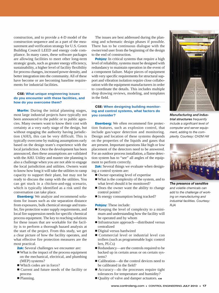
Manufacturing and indus-trial structures frequently include a significant level of computer and server equip-ment, adding to the com-plexity. Courtesy: CH2M Hill
The presence of sensitiveand volatile chemicals can add to the challenge of work-ing on manufacturing and industrial facilities. Courtesy: RJA
Manufacturing and indus-
The presence of sensitive

18 ● MONTH 2013 CONTROL ENGINEERING ● www.controleng.com
Control Engineering Europe
www.controlengeurope.com
Go Online
Speaking at Hannover Messe, Siegfried Russ-wurm, CEO of Siemens Industry Sector, said: “Never before has the world of manufacturing and production technol-ogy been changing as rapidly and fundamen-tally as today. Courtesy: Control Engineering Europe
18 ● JULY 2012 CONTROL ENGINEERING ● www.controleng.com
Industry 4.0 was high on the agenda of many Hannover Messe exhibitors, according to Control Engineering Europe. Referred to by many as the “fourth industrial revolution,”
the concept of Industry 4.0 is to merge the virtual world with the real world, bringing IT and pro-duction closer together. Horizontal integration, from product to production, is one of its major ambitions. Industry 4.0 now also forms the cor-nerstone of the German government’s high-tech strategy to secure the competitiveness of German industry.
Siemens showcased how it, and its custom-ers, will meet today’s challenges and shape the new production age. Speaking at Hannover Fair, Siegfried Russwurm, CEO of Siemens Indus-try Sector, said: “Never before has the world of manufacturing and production technology been changing as rapidly and fundamentally as today.
Although Russwurm believes that there is some way to go before Industry 4.0 becomes reality, Siemens is already laying the essential foundations for its implementation. A decisive role will be played by industrial software that allows the integration of product development and production, and consequently paves the way for the holistic optimization of product develop-ment and production processes.
Before the Hannover event CEE spoke with Eckard Eberle, CEO of Industrial Automation Systems, Siemens Industry Sector, to find out more about fast-changing industry needs.
“Industry is getting more complex,” he said. “Products need to get to market in ever-shorter time frames, which requires the whole develop-ment and production phases to be shorter too. The product and production design processes will need to more closely collaborate. The infor-mation created in the design phase needs to be used to a greater degree throughout the pro-duction process.” Originally it took more than one week, from conclusion of a product design change, to create a Rolls Royce work plan for the shop floor at a U.K. plant. “Siemens helped the company to more closely integrate its system with the company’s MES. They now can make changes in two or three hours.
“We have many examples where such inte-gration is taking place. However, we expect that, within the next 10 to 20 years, the entire data flow will be seamless.”
Safety challengesAs the automation landscape continues to
develop, companies also face new safety chal-lenges. New safety objectives include, for exam-ple, the protection of production data, product and plagiarism protection, know-how protection, access protection integrity protection, and remote maintenance.
“Pilz is playing its part in ensuring that safety is recognized as a critical success factor in Indus-try 4.0,” said Susanne Kunschert, director at Pilz GmbH & Co. “We are advocating a holistic approach to protection in both its forms, safety and security. We want to use our experience from the machinery safety and automation sectors to drive this important work forward.”
On the product side, Pilz is pursuing a modu-lar, distributable approach to enable the benefits of a decentralized control structure without the increased complexity that would normally result when programs are distributed on different con-trol systems. Pilz predicts that intelligent sensors and actuators in distributed systems will increas-ingly assume the functions of control systems. Improved interaction between machine modules, as well as between human and machine is the aim.
Safe motion controllers (interconnected syn-chronously and safely via real-time Ethernet) already support local control and evaluation functions. Pilz is moving in this direction with its intelligent camera systems for safe, three-dimensional zone monitoring and camera-based protection and measuring systems. ce
- Suzanne Gill is editor of Control Engineer-ing Europe; this article appeared on www.con-trolengeurope.com on June 12, 2013, and was edited for Control Engineering.
See more in this article online from Beckhoff Automation, Belden, Control Techniques (Emer-son Industrial Automation), and Eaton, at www.controleng.com/archive, June.
Suzanne Gill
Industry prepares for thenext industrial revolutionAutomation companies share views on the fourth industrial revolution, Industry 4.0,according to Control Engineering Europe.
INTERNATIONALINTERNATIONAL®
www.controleng.com ● CONTROL ENGINEERING JULY 2013 ● 19
Before installing industrial wireless equipment, careful testing can prevent potential problems and reduce trouble-shooting time following an installation.
Proof of concept helps ensure correct radio selection for the job. In most cases, the first step is to conduct a software path loss study. Distanc-es under 305 m (1,000 ft) usually do not require such a study. A simple test can be done with a functional radio set to the desired wireless mode, transmit data rate, and transmit power setting.
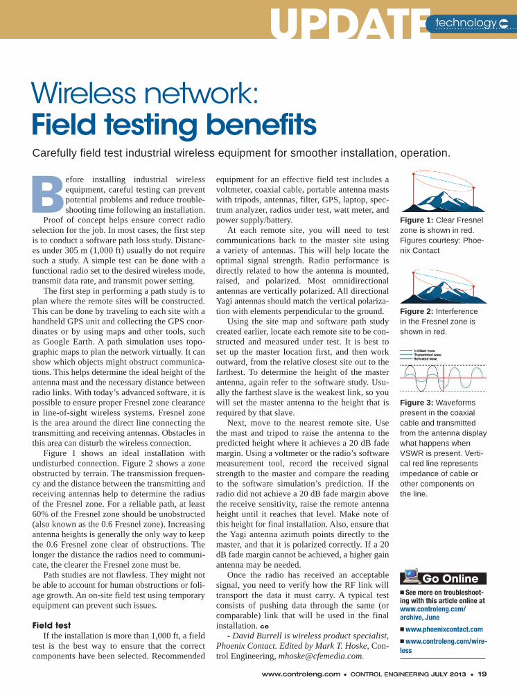
The first step in performing a path study is to plan where the remote sites will be constructed. This can be done by traveling to each site with a handheld GPS unit and collecting the GPS coor-dinates or by using maps and other tools, such as Google Earth. A path simulation uses topo-graphic maps to plan the network virtually. It can show which objects might obstruct communica-tions. This helps determine the ideal height of the antenna mast and the necessary distance between radio links. With today’s advanced software, it is possible to ensure proper Fresnel zone clearance in line-of-sight wireless systems. Fresnel zone is the area around the direct line connecting the transmitting and receiving antennas. Obstacles in this area can disturb the wireless connection.
Figure 1 shows an ideal installation with undisturbed connection. Figure 2 shows a zone obstructed by terrain. The transmission frequen-cy and the distance between the transmitting and receiving antennas help to determine the radius of the Fresnel zone. For a reliable path, at least 60% of the Fresnel zone should be unobstructed (also known as the 0.6 Fresnel zone). Increasing antenna heights is generally the only way to keep the 0.6 Fresnel zone clear of obstructions. The longer the distance the radios need to communi-cate, the clearer the Fresnel zone must be.
Path studies are not flawless. They might not be able to account for human obstructions or foli-age growth. An on-site field test using temporary equipment can prevent such issues.
Field testIf the installation is more than 1,000 ft, a field
test is the best way to ensure that the correct components have been selected. Recommended
equipment for an effective field test includes a voltmeter, coaxial cable, portable antenna masts with tripods, antennas, filter, GPS, laptop, spec-trum analyzer, radios under test, watt meter, and power supply/battery.
At each remote site, you will need to test communications back to the master site using a variety of antennas. This will help locate the optimal signal strength. Radio performance is directly related to how the antenna is mounted, raised, and polarized. Most omnidirectional antennas are vertically polarized. All directional Yagi antennas should match the vertical polariza-tion with elements perpendicular to the ground.
Using the site map and software path study created earlier, locate each remote site to be con-structed and measured under test. It is best to set up the master location first, and then work outward, from the relative closest site out to the farthest. To determine the height of the master antenna, again refer to the software study. Usu-ally the farthest slave is the weakest link, so you will set the master antenna to the height that is required by that slave.
Next, move to the nearest remote site. Use the mast and tripod to raise the antenna to the predicted height where it achieves a 20 dB fade margin. Using a voltmeter or the radio’s software measurement tool, record the received signal strength to the master and compare the reading to the software simulation’s prediction. If the radio did not achieve a 20 dB fade margin above the receive sensitivity, raise the remote antenna height until it reaches that level. Make note of this height for final installation. Also, ensure that the Yagi antenna azimuth points directly to the master, and that it is polarized correctly. If a 20 dB fade margin cannot be achieved, a higher gain antenna may be needed.
Once the radio has received an acceptable signal, you need to verify how the RF link will transport the data it must carry. A typical test consists of pushing data through the same (or comparable) link that will be used in the final installation. ce
- David Burrell is wireless product specialist, Phoenix Contact. Edited by Mark T. Hoske, Con-trol Engineering, [email protected].
UPDATEUPDATEWireless network:Field testing benefits
technology
Carefully field test industrial wireless equipment for smoother installation, operation.
� See more on troubleshoot-ing with this article online at www.controleng.com/archive, June
� www.phoenixcontact.com
� www.controleng.com/wire-less
Go Online
Figure 1: Clear Fresnel zone is shown in red. Figures courtesy: Phoe-nix Contact
Figure 2: Interference in the Fresnel zone is shown in red.
Figure 3: Waveforms present in the coaxial cable and transmitted from the antenna display what happens when VSWR is present. Verti-cal red line represents impedance of cable or other components on the line.
input #11 at www.controleng.com/information
w
20 ● JULY 2013 CONTROL ENGINEERING ● www.controleng.com
Are automation suppliers truly c o n s i d e r i n g farming out the
design and safety certifica-tion effort of integrating functional safety features into existing components? This functional safety topic is receiving significant chat-ter on the Internet and in the media.
Well, it seems that there are some engineering firms that spe-cialize in this capability and offer these services to various automation suppli-ers. This strategy appears to be based on various factors:
1. Market demand has increased for automation products with functional safe-ty features. For example, drive systems can have a safe stop, safe torque off, etc., with safety functionality built in.
2. Time to market can be shortened by using experienced, qualified engi-neering firms to provide these services.
3. Automation companies typically incur incremental costs to grow spe-cialized internal safety certified orga-nizational know-how to perform these services.
4. Increased market demand comes from an increasing awareness of reduced lifecycle costs of ownership through “safety automation” versus hardwired safety applications.
You probably think, “Great stuff!” Right?
Caution: Don’t be too quick to run to the bank. As an end user, just because your favorite automation supplier quickly brought you a safety certified component doesn’t necessarily mean it’s capable of full service to you as its customer. Farm-ing out the design and cer-tification effort is only one
spoke in the wheel of resources required by automation suppliers to support their safety automation products. They will also need pre-sales support, post-sale service support, and training sup-port, to name a few. You wouldn’t want to phone your automation supplier’s 24-hour hotline only to be transferred to its engineering firm subcontractor (for functional safety) and then to the sub-contractor’s voicemail. After all, reduc-ing unplanned machine downtime was supposed to be part of your return-on-investment decision.
So, you might want to ask your favor-ite automation supplier a few questions related to the topics above before decid-ing. ce
- J.B. Titus, Certified Functional Safety Expert (CFSE), writes the Control Engineering Machine Safety Blog. Reach him at [email protected].
SAFETYw SAFETYmachine
Farming out functional safety?What are the consequences of farming out the “designing in” of functional safety component requirements? See four factors to consider and one caution.
� Engineering interaction: Go to this blog at www.controleng.com/blogs, see related articles:
� Inside Machines: Does adopting ISO 13849-1:2006 change the U.S. model for compliance and enforcement?
� Machine safety: Incorporating functional safety as part of your machine safety plan, Part 4
� Machine safety and functional safety: Which type?
� Machine safety: Functional safety and the steps to be compliant in the U.S.
Go Online
J.B. Titus, CFSE,Certified Functional
Safety Expert (CFSE)
w
• System-wide communicat ion, process contro l and moni tor ing
• Powerfu l so lut ions for product and process in tegrat ion
• From construct ion to custom programming - panels and systems integrat ion d esigned for your speci f ic needs
VICFrom Individual Control Panels,
To CompleteSystems Integration
- OEMs - Let us Be Your Panel Builderand Systems Integrator!
Phone: (336) 793-2658 • viccontrols.com
www.controleng.com ● CONTROL ENGINEERING JULY 2013 ● 21
Apologies to the International Society of Automation, but you may not need to buy the concise little guidebook that I authored and the ISA just pub-
lished—the book with the anything-but-concise title, “The Automation Legal Reference, a Guide to Legal Risk in the Automation, Robotics and Process Industries.”
The reason buying may be optional is that for the past two months I have been giving away for free the essential “takeaways” from each of that book’s 21 chapters. I have parceled these out via social media and speeches [including at the Con-trol System Integrator (CSIA) 2013 Executive Conference].
Below all 21 are listed. Control Engineering magazine is the place where many of these take-aways originated. In the electronic version of this article, you can find links to a number of these initial articles.
Here are the 21 actionable insights that I believe are essential to minimizing risk in indus-trial engineering projects:
1. Automation projects are a type of con-struction project. This is my central insight. An automation project is not the sale of equipment. It’s not a software deliverable. It’s the construc-tion of a system.
Well-worn construction law principles apply, but a gap needs to be bridged between lawyers and engineers. Each needs to speak the other’s dialect.
2. Know your project delivery method.You can’t find a tree if you can’t find the forest. Knowing the “delivery method” defines—most importantly—which company owns which part of the design.
Most automation projects fall under the method called “design-build,” but that comes with consequences. Those consequences need to be considered (and the important exceptions identified).
3. Standard contract forms don’t work.Yes, it’s a construction project, but the standard AIA and other trade association forms fall short.
Among other things, the warranties are not appropriate for software, the concepts of test-ing and commissioning are not even mentioned, and don’t even get me started on intellectual property.
4. Both systems and contracts need inte-gration. Integration in the contract sense means the scope of work is nailed down and boxed up. Without it, the goalposts are on rails.
5. Limitation of liability is the king of all key contract terms. If you give attention to no other contract term, pay attention to this one. The rest of the Dirty Dozen provisions of contracts are also important, but they pale in comparison to the king.
6. The beauty of a contract clause is in the eye of the beholder. Of course, whether something rises to the level of the Dirty Dozen or the Other Ugly Eight potentially troublesome contract clauses is a matter of perspective. For instance, “free from defects,” while empowering the end user, should not be endured by those that deliver software.
7. Risk should be placed on the party in the best position to control it. It’s the most com-pelling argument that can be made while nego-tiating an automation agreement—and, what’s more, it’s in the best interest of all.
8. Lack of clarity in specs usually serves no one—except the lawyers.
9. Not valuing IP is leaving money on the table. Because most automation projects involve creatively solving a physical problem, the solu-tions can have great value.
It’s not an all-or-nothing proposition; owner-ship can be shared. Give attention to the possi-
LEGALITIESLEGALITIES
Automation projects are like construction projects, know your project delivery method,and standard contracts don’t work are the first three of 21 points of advice.
Mark Voigtmann,Faegre Baker Daniels
legal takeawaysfor the automation industry 21
automation
input #12 at www.controleng.com/information 22 ● JULY 2013 CONTROL ENGINEERING
bilities and opportunities involved.
10. Identify, then classify relevant automation standards. There are standards, and then there are standards. Some are binding, some not. Knowing which is which is—how can I put this—helpful.
11. The number one risk in not being licensed is not getting paid. Each country, state, and province has unique means of regulating—or not—those who work in the automation profession.
Even if you are in one of those places that do, the odds of your company being challenged by a state agency may be small. Customers, on the other hand, may use it as an excuse not to pay.
12. Speak “green” to win more business (and to avoid liability). The upside of knowing about LEED and Green Globes is getting in the door when a competitor cannot. The downside can be suffering performance specs based on attain-ing LEED criteria.
13. Good e-mail hygiene wins the case. This means company-wide discipline. Sticking to the “story.” Quoting the
contract exactly. Using the phrase “among other things” to keep the door open to additional points.
14. Asserting a claim is an investment (that should be analyzed like any other investment). You would not buy a stock where the trans-action cost is greater than the poten-tial gain. The same goes for litigation. Litigating rarely makes sense, and even when it does, there are important matters to monitor.
15. Avoiding negligence liabil-ity means giving attention to process, contracts, and insurance. Process is pre-vention. Contracts are avoidance. Insur-
ance is mitigation.
16. No business mess is insured, and every business mess is insured. What your insurance company tells you in the face of a significant loss frequently is not the last word.
17. Liens and bonds are backup pots of money. If the company that owes money does not have it, these represent Plan B.
18. The most important parts of a service agreement are the exclusions. Being “on call” is a part of every mainte-nance and service agreement. But when does a service call turn into a new project? Your exclusions provide the answer.
19. Beware the solvency of the middleman. Did I men-tion that liens and bonds are backup pots of money?
20. Conduct an audit of your legal health. Smart docu-mentation for projects is only the external piece of the com-pany versus legal risk continuum. The internal piece also needs attention.
21. Your lawyer and you should work from the same playbook. It is the difference between your lawyer being a part of the problem or the solution. ce
- Mark Voigtmann leads the automation practice at Faegre Baker Daniels, a law firm with offices in the U.S., the U.K., and China. “The Automation Legal Reference” can be pur-chased at the ISA bookstore at www.isa.org/books. Edited by Mark T. Hoske, content manager, Control Engineering, [email protected].
LEGALITIESLEGALITIESautomation
� www.controleng.com/archive July 2013 has links to more Voigtmann advice with this article online.
� www.faegrebd.com
� www.controlsys.org (CSIA)
Go Online
‘Good e-mail hygiene means sticking to the
story and quoting the contract exactly,
among other things.’
www.controleng.com ● CONTROL ENGINEERING JULY 2013 ● 23
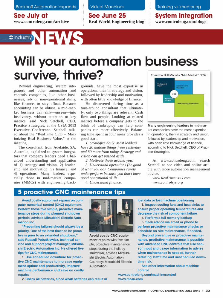
Beyond engineering, system inte-grators and other automation and controls companies, like other busi-nesses, rely on non-operational skills, like finance, to stay afloat. Because accounting can be obtuse, a mid-mar-ket business can sink—unseen—into insolvency, without attention to key metrics, said Nick Setchell, CEO, Practice Strategies, at the CSIA 2013 Executive Conference. Setchell talk-ed about the “RealTime CEO – Max-imizing Real Business Value,” at the meeting.
The consultant, from Adelaide, SA, Australia, explained to system integra-tors that company leaders need a bal-anced understanding and application of 1) strategy and vision, 2) leader-ship and motivation, 3) finance, and 4) operations. Many leaders, espe-cially those in mid-market compa-nies (MMCs) with engineering back-
grounds, have the most expertise in operations, then in strategy and vision, followed by leadership and motivation, with often little knowledge of finance.
He discovered during time as a turn-around consultant that ultimate-ly, only two things are relevant: Cash flow and people. Looking at related metrics before a company gets to the brink of bankruptcy can help com-panies run more effectively. Balanc-ing time spent in four areas provides a good start.
1. Strategize daily. Most leaders have 20 undone things from yesterday and 80 more from today. Strategy and vision can get pushed aside.
2. Motivate those around you. 3. Understand operations (be good
at what you do). Companies rarely underperform because you don’t have good operational skills.
4. Understand finance.
At www.controleng.com, search Setchell to see video and online arti-cle with more automation management advice.
www.RealTimeCEO.comwww.controlsys.org
Will your automation business survive, thrive?
NEWSNEWSindustry
System Integrationwww.controleng.com/blogs
See July at www.controleng.com/archive
See June 25Real World Engineering blog
Beckhoff Automation expands Virtual Machines Training vs. mentoring
Many engineering leaders in mid-mar-ket companies have the most expertise in operations, then in strategy and vision, followed by leadership and motivation, with often little knowledge of finance, according to Nick Setchell, CEO of Prac-tice Strategies.
5 proactive CNC maintenance tipsAvoid costly equipment repairs on com-
puter numerical control (CNC) equipment. Perform these five simple, proactive main-tenance steps during planned shutdown periods, advised Mitsubishi Electric Auto-mation Inc.
“Preventing failures should always be a priority. One of the best times to be proac-tive is prior to an extended shutdown,” said Russell Pobutkiewicz, technical ser-vice and support project manager, Mitsubi-shi Electric Automation Inc. He offered five tips for CNC maintenance.
1. Use scheduled downtime for proac-tive CNC maintenance to increase equip-ment uptime and productivity, improve machine performance and save on costly repairs
2. Check all batteries, since weak batteries can result in
lost data or lost machine positioning3. Inspect cooling fans and heat sinks to
ensure proper operating temperatures and decrease the risk of component failure
4. Perform a full memory backup5. Seek advice via email or phone to
perform proactive maintenance checks or schedule on-site maintenance, if needed.
Beyond preventive or proactive mainte-nance, predictive maintenance is possible with advanced CNC controls that use sen-sor input and usage information to advise when maintenance is needed, further reducing staff time and unscheduled down-time risk.
See other information about machine control.
www.controleng.com/machinecontrol www.meau.com
Avoid costly CNC equip-ment repairs with five sim-ple, proactive maintenance steps during the holiday shutdown, advises Mitsubi-shi Electric Automation. Courtesy: Mitsubishi Electric Automation
24 ● JULY 2013 CONTROL ENGINEERING ● www.controleng.com
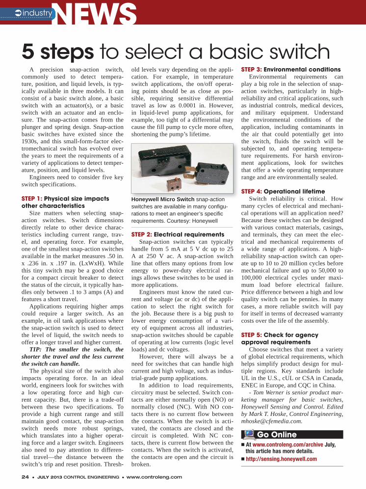
A precision snap-action switch, commonly used to detect tempera-ture, position, and liquid levels, is typ-ically available in three models. It can consist of a basic switch alone, a basic switch with an actuator(s), or a basic switch with an actuator and an enclo-sure. The snap-action comes from the plunger and spring design. Snap-action basic switches have existed since the 1930s, and this small-form-factor elec-tromechanical switch has evolved over the years to meet the requirements of a variety of applications to detect temper-ature, position, and liquid levels.
Engineers need to consider five key switch specifications.
STEP 1: Physical size impacts other characteristics
Size matters when selecting snap-action switches. Switch dimensions directly relate to other device charac-teristics including current range, trav-el, and operating force. For example, one of the smallest snap-action switches available in the market measures .50 in. x .236 in. x .197 in. (LxWxH). While this tiny switch may be a good choice for a compact circuit breaker to detect the status of the circuit, it typically han-dles only between .1 to 3 amps (A) and features a short travel.
Applications requiring higher amps could require a larger switch. As an example, in oil tank applications where the snap-action switch is used to detect the level of liquid, the switch needs to offer a longer travel and higher current.
TIP: The smaller the switch, the shorter the travel and the less current the switch can handle.
The physical size of the switch also impacts operating force. In an ideal world, engineers look for switches with a low operating force and high cur-rent capacity. But, there is a trade-off between these two specifications. To provide a high current range and still maintain good contact, the snap-action switch needs more robust springs, which translates into a higher operat-ing force and a larger switch. Engineers also need to pay attention to differen-tial travel—the distance between the switch’s trip and reset position. Thresh-
old levels vary depending on the appli-cation. For example, in temperature switch applications, the on/off operat-ing points should be as close as pos-sible, requiring sensitive differential travel as low as 0.0001 in. However, in liquid-level pump applications, for example, too tight of a differential may cause the fill pump to cycle more often, shortening the pump’s lifetime.
STEP 2: Electrical requirementsSnap-action switches can typically
handle from 5 mA at 5 V dc up to 25 A at 250 V ac. A snap-action switch line that offers many options from low energy to power-duty electrical rat-ings allows these switches to be used in more applications.
Engineers must know the rated cur-rent and voltage (ac or dc) of the appli-cation to select the right switch for the job. Because there is a big push to lower energy consumption of a vari-ety of equipment across all industries, snap-action switches should be capable of operating at low currents (logic level loads) and dc voltages.
However, there will always be a need for switches that can handle high current and high voltage, such as indus-trial-grade pump applications.
In addition to load requirements, circuitry must be selected. Switch con-tacts are either normally open (NO) or normally closed (NC). With NO con-tacts there is no current flow between the contacts. When the switch is acti-vated, the contacts are closed and the circuit is completed. With NC con-tacts, there is current flow between the contacts. When the switch is activated, the contacts are open and the circuit is broken.
STEP 3: Environmental conditionsEnvironmental requirements can
play a big role in the selection of snap-action switches, particularly in high-reliability and critical applications, such as industrial controls, medical devices, and military equipment. Understand the environmental conditions of the application, including contaminants in the air that could potentially get into the switch, fluids the switch will be subjected to, and operating tempera-ture requirements. For harsh environ-ment applications, look for switches that offer a wide operating temperature range and are environmentally sealed.
STEP 4: Operational lifetimeSwitch reliability is critical. How
many cycles of electrical and mechani-cal operations will an application need? Because these switches can be designed with various contact materials, casings, and terminals, they can meet the elec-trical and mechanical requirements of a wide range of applications. A high-reliability snap-action switch can oper-ate up to 10 to 20 million cycles before mechanical failure and up to 50,000 to 100,000 electrical cycles under maxi-mum load before electrical failure. Price difference between a high and low quality switch can be pennies. In many cases, a more reliable switch will pay for itself in terms of decreased warranty costs over the life of the assembly.
STEP 5: Check for agency approval requirements
Choose switches that meet a variety of global electrical requirements, which helps simplify product design for mul-tiple regions. Key standards include UL in the U.S., cUL or CSA in Canada, ENEC in Europe, and CQC in China.
- Tom Werner is senior product mar-keting manager for basic switches, Honeywell Sensing and Control. Edited by Mark T. Hoske, Control Engineering, [email protected].
5 steps to select a basic switch
NEWSNEWSindustry
Honeywell Micro Switch snap-action switches are available in many configu-rations to meet an engineer’s specific requirements. Courtesy: Honeywell
� At www.controleng.com/archive July, this article has more details.� http://sensing.honeywell.com
Go Online

WE GUARANTEE IT WON’TIn manufacturing time is money. The smallest dust or debris can cause big problems for your electronics on the manufacturing floor. We guar-antee IceStation TITAN will keep your critical computer systems up and running no matter what danger presents itself. Built to meet NEMA 12 standards, IceStation TITAN protects computer systems from harmful dust, grease, sparks, and splashing fluids. With a large viewing window designed to accommodate up to 24’’ wide screen monitors, a retractable keyboard drawer, oversized work surface, and a track record of 27 years experience protecting electronics, ITSENCLOSURES is the one name you can trust. To learn more about IceStation TITAN, call 1.800.423.9911 or visit ITSENCLOSURES.com.
25 25
input #13 at www.controleng.com/informationCONTROL ENGINEERING JULY 2013 ● 25
computing, mobility of production data, and network security are among topics. Labs include networking security best practices for securing data. Several cus-tomer-led sessions from manufacturers covered process automation, manu-facturing intelligence, visualization, machine safety, industrial networking,
Internet of Things, and security, among other topics. The event had more than 150 sessions, labs, and workshops from Cisco Systems, Microsoft, Kraft Foods Group, Enbridge, Ball Corp., Livzon Pharmaceuticals, and others.
www.rockwellautomation.com www.RSTechED.com
Manufacturers seek benefits from increased connectivityCommercial communication tech-
nologies are quickly migrating onto plant floors, creating opportunities, and potential risks, for manufacturers. Dur-ing its 2013 RSTechED event, Rockwell Automation offers approaches to help manufacturers securely integrate “dis-ruptive” technologies (such as mobile devices, cloud computing, and virtu-alization), to help build a “Connected Enterprise,” the theme of this year’s
conference, in San Diego, June 9 to 14.
“Disruptive technologies can enable collaboration across all levels in manu-facturing organizations,” explained Sujeet Chand, senior vice president and chief technology officer at Rockwell Automation and one of the scheduled keynote speakers at event. “By connect-ing the entire enterprise, manufacturers can fully harness the information they need to optimize their operations.”
In the keynote address, Chand and Frank Kulaszewicz, senior vice president, architecture and software, Rockwell Automation, explored how the adoption of disruptive technologies is
transforming industrial automation.“Manufacturing needs to be more
smart, productive, secure, and sustain-able. Collaboration sparks innovation to improve overall productivity and sustainability,” said Kulaszewicz. “The connected enterprise allows true col-laboration” among plant personnel, but production subsystems, the plant floor, and enterprise IT systems. “But first, manufacturers need a smart and secure infrastructure.”
Tracks and sessions examine the disruptive technologies driving the con-nected enterprise. Case studies, new technologies, system integration, cloud
Frank Kulaszewicz is senior vice president, architecture and software, at Rockwell Automation.
Sujeet Chand is senior vice president and chief technology officer at Rock-well Automation. Images courtesy: CFE Media, Mark T. Hoske
26 ● JULY 2013 CONTROL ENGINEERING ● www.controleng.com
Ever since PC-based software was introduced to industrial automation, the once very separate worlds of com-mercial off-the-shelf (COTS) and industrial technologies have become
more aligned. Many readers will remember when PC-based software was first introduced for HMI/SCADA systems in the mid-1980s. At the time, there were concerns with reliability and speed of response, but PC-based software is now the de facto standard when it comes to HMI pack-ages, both for operator interface and SCADA applications.
HMI applications now routinely run on both
office-grade and industrial PCs, and the soft-ware used to program these applications is also PC-based. At the same time, SCADA technolo-gies are advancing to enable manufacturers to reduce costs through the use of COTS applica-tions (see Table 1).
The word “influence” is important because industrial automation devices are not and will not be duplicates of COTS devices. An industrial PC may have the look and feel as well as some of the underlying technology of a COTS PC, but it’s also designed to withstand the demands of harsh environments, and often also includes other fea-tures to increase reliability such as solid-state data storage.
Just as desktops were replaced with laptops in many instances, laptops are now being replaced by tablets and smartphones with multi-touch tech-nologies. This trend is also moving into industri-al settings. In addition to the way we access HMI systems, the way data is manipulated and stored is being transformed by SCADA technologies for devices first developed for personal use.
Corporations are recognizing and react-ing to these trends. A recent study by the Gart-ner research firm predicts that about half of the
Fabio Terezinho
The HMI of the future will look very familiarHMI/SCADA applications enable companies to benefit from commercial off-the-shelf technologies adapted for industrial automation to lower costs and improve operations.
cover story
Figure 1: Today’s SCADA packages enable workers to monitor and control remote areas on tablets and smartphones. All photos courtesy: InduSoft
Table 1: SCADA for COTS technologies improves operations:
n SCADA systems accessed by smart phones and tablets provide faster and less expensive remote access.
n SCADA systems for multi-touch screens are intuitive for both younger and mature workers.
n Multi-touch commands can be executed three times faster than keystrokes and mouse clicks.
n Multi-touch screens are better suited to harsh environments.
n Cloud-based HMI/SCADA drastically reduces costs associated with purchasing and maintaining hardware and software for data storage and access.
n Cloud providers are expert at implementing the latest security measures.
n Multiple Internet providers and diverse server locations protect access to data in cloud-based HMI/SCADA.
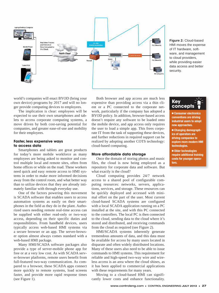
www.controleng.com ● CONTROL ENGINEERING JULY 2013 ● 27
Figure 2: Cloud-based HMI moves the expense of IT hardware, soft-ware, and management to cloud providers, while providing easier data access and better security.
world’s companies will enact BYOD (bring your own device) programs by 2017 and will no lon-ger provide computing devices to employees.
The implication is clear: employees will be expected to use their own smartphones and tab-lets to access corporate computing systems, a move driven by both cost-saving potential for companies, and greater ease-of-use and mobility for their employees.
Faster, less expensive waysto access data
Smartphones and tablets are great products for today’s more mobile workforce as many employees are being asked to monitor and con-trol multiple local and remote sites, often from home offices or while on the road. These workers need quick and easy remote access to HMI sys-tems in order to make more informed decisions away from the control room, and what better way than to utilize devices that they are already inti-mately familiar with through everyday use.
One of the factors powering this movement is SCADA software that enables users to access automation systems as easily on their smart-phones in the field as they do in the plant. Autho-rized users needing remote real-time access can be supplied with either read-only or two-way access, depending on their specific duties and responsibilities. From handheld devices, users typically access web-based HMI systems via a secure browser or an app. The server-brows-er option almost always comes standard with a web-based HMI package.
Many HMI/SCADA software packages also provide a type of server-mobile phone app for free or at a very low cost. As with SCADA serv-er-browser platforms, remote users benefit from full-featured two-way communication. As com-pared to a browser, these SCADA apps connect more quickly to remote systems, load screens faster, and provide more rapid response times (see Figure 1).
Both browser and app access are much less expensive than providing access via a thin cli-ent or a PC connected to the corporate net-work, particularly if the company has adopted a BYOD policy. In addition, browser-based access doesn’t require any software to be loaded onto the mobile device, and app access only requires the user to load a simple app. This frees corpo-rate IT from the task of supporting these devices, and further reductions in required support can be realized by adopting another COTS technology: cloud-based computing.
More affordable data storageOnce the domain of storing photos and music
files, the cloud is now being employed as a repository for corporate data and software. But what exactly is the cloud?
Cloud computing provides 24/7 network access to a shared pool of configurable com-puting resources: networks, servers, applica-tions, services, and storage. These resources can be quickly deployed and accessed with mini-mal effort on the part of the user. Most current cloud-based SCADA systems are configured with a local SCADA application running on a PC installed at the site, and with this PC connected to the controllers. The local PC is then connected to the cloud, sending data to the cloud where it’s stored and distributed, and receiving commands from the cloud as required (see Figure 2).
HMI/SCADA systems inherently generate tremendous amounts of data, and this data must be available for access by many users located in disparate and often widely distributed locations. Many of these users also need to be able to issue commands to HMI systems. This requirement for reliable and high-speed two-way wire and wire-less access is an area where the cloud shines, as it has been applied to commercial applications with these requirements for many years.
Moving to a cloud-based HMI can signifi-cantly lower costs and enhance functionality.
Keyconcepts� Consumer electronics conventions are driving industrial users to adopt new approaches.
� Changing demograph-ics of operators are driving companies to explore more modern HMI technologies.
� Older technologies require additional training costs for younger opera-tors.
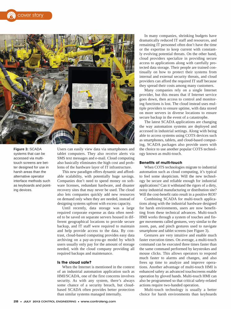
28 ● JULY 2013 CONTROL ENGINEERING ● www.controleng.com
Users can easily view data via smartphones and tablet computers. They also receive alerts via SMS text messages and e-mail. Cloud computing also basically eliminates the high cost and prob-lems of the hardware layer of IT infrastructure.
This new paradigm offers dynamic and afford-able scalability, with potentially huge savings. Companies don’t need to spend money on soft-ware licenses, redundant hardware, and disaster recovery sites that may never be used. The cloud also lets companies quickly add new resources on demand only when they are needed, instead of designing systems upfront with excess capacity.
Until recently, data storage was a large required corporate expense as data often need-ed to be saved on separate servers housed in dif-ferent geographical locations to provide secure backup, and IT staff were required to maintain and help provide access to the data. By con-trast, cloud-based computing provides easy data archiving on a pay-as-you-go model by which users usually only pay for the amount of storage needed, with the cloud company providing all required backups and maintenance.
Is the cloud safe?When the Internet is mentioned in the context
of an industrial automation application such as HMI/SCADA, one of the first concerns involves security. As with any system, there’s always some chance of a security breach, but cloud-based SCADA often provides better protection than similar systems managed internally.
In many companies, shrinking budgets have dramatically reduced IT staff and resources, and remaining IT personnel often don’t have the time or the expertise to keep current with constant-ly evolving potential threats. On the other hand, cloud providers specialize in providing secure access to applications along with carefully pro-tected data storage. Their people are trained con-tinually on how to protect their systems from internal and external security threats, and cloud providers can afford the required IT staff because they spread their costs among many customers.
Many companies rely on a single Internet provider, but this means that if Internet service goes down, then access to control and monitor-ing functions is lost. The cloud instead uses mul-tiple providers to ensure uptime, with data stored on more servers in diverse locations to ensure secure backup in the event of a catastrophe.
The latest SCADA applications are changing the way automation systems are deployed and accessed in industrial settings. Along with being able to access systems using COTS devices such as smartphones, tablets, and cloud-based comput-ing, SCADA packages also provide users with the choice to use another popular COTS technol-ogy known as multi-touch.
Benefits of multi-touchWhen COTS technologies migrate to industrial
automation such as cloud computing, it’s typical to feel some skepticism. Will the new technol-ogy be secure and reliable enough for industrial applications? Can it withstand the rigors of a dirty, noisy industrial manufacturing or distribution site? Will the cost-benefit ratio result in a positive ROI?
Combining SCADA for multi-touch applica-tions along with the industrial hardware designed for harsh environments, users are now benefit-ting from these technical advances. Multi-touch HMI works through a system of touches and fin-ger movements called gestures, very similar to the zoom, pan, and pinch gestures used to navigate smartphone and tablet screens (see Figure 3).
Gestures are very intuitive and enable much faster execution times. On average, a multi-touch command can be executed three times faster than the same command performed by keystrokes and mouse clicks. This allows operators to respond much faster to alarms and changes, and also frees up time to analyze and improve opera-tions. Another advantage of multi-touch HMI is enhanced safety as advanced touchscreens enable operation by gloved hands. Multi-touch HMI can also be programmed so that critical safety-related actions require two-handed operation.
Multi-touch technology is usually a better choice for harsh environments than keyboards
cover story
Figure 3: SCADA systems that can be accessed via multi-touch screens are bet-ter designed for use in harsh areas than the alternative operator interface methods such as keyboards and point-ing devices.
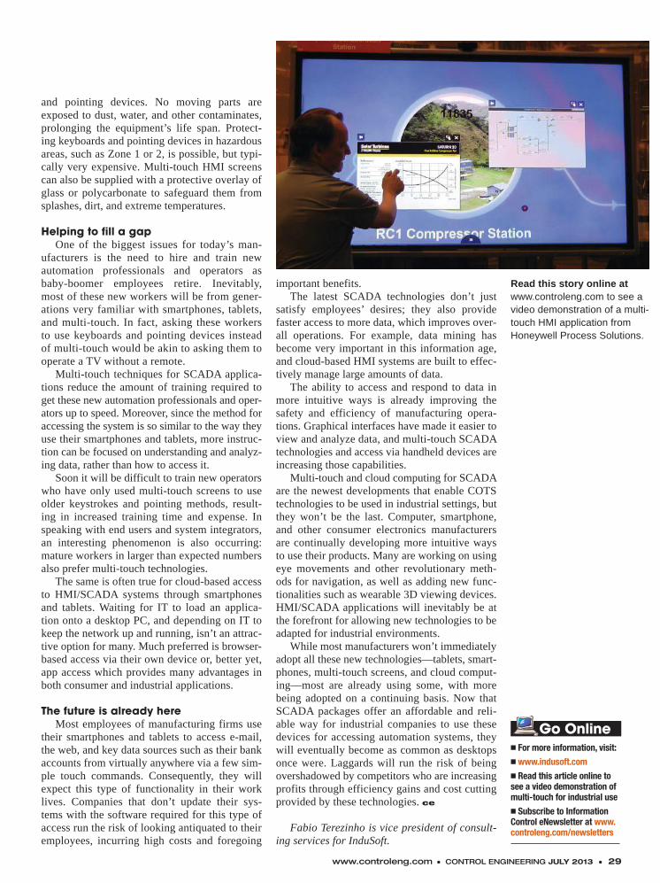
www.controleng.com ● CONTROL ENGINEERING JULY 2013 ● 29
and pointing devices. No moving parts are exposed to dust, water, and other contaminates, prolonging the equipment’s life span. Protect-ing keyboards and pointing devices in hazardous areas, such as Zone 1 or 2, is possible, but typi-cally very expensive. Multi-touch HMI screens can also be supplied with a protective overlay of glass or polycarbonate to safeguard them from splashes, dirt, and extreme temperatures.
Helping to fill a gapOne of the biggest issues for today’s man-
ufacturers is the need to hire and train new automation professionals and operators as baby-boomer employees retire. Inevitably, most of these new workers will be from gener-ations very familiar with smartphones, tablets, and multi-touch. In fact, asking these workers to use keyboards and pointing devices instead of multi-touch would be akin to asking them to operate a TV without a remote.
Multi-touch techniques for SCADA applica-tions reduce the amount of training required to get these new automation professionals and oper-ators up to speed. Moreover, since the method for accessing the system is so similar to the way they use their smartphones and tablets, more instruc-tion can be focused on understanding and analyz-ing data, rather than how to access it.
Soon it will be difficult to train new operators who have only used multi-touch screens to use older keystrokes and pointing methods, result-ing in increased training time and expense. In speaking with end users and system integrators, an interesting phenomenon is also occurring: mature workers in larger than expected numbers also prefer multi-touch technologies.
The same is often true for cloud-based access to HMI/SCADA systems through smartphones and tablets. Waiting for IT to load an applica-tion onto a desktop PC, and depending on IT to keep the network up and running, isn’t an attrac-tive option for many. Much preferred is browser-based access via their own device or, better yet, app access which provides many advantages in both consumer and industrial applications.
The future is already hereMost employees of manufacturing firms use
their smartphones and tablets to access e-mail, the web, and key data sources such as their bank accounts from virtually anywhere via a few sim-ple touch commands. Consequently, they will expect this type of functionality in their work lives. Companies that don’t update their sys-tems with the software required for this type of access run the risk of looking antiquated to their employees, incurring high costs and foregoing
important benefits.The latest SCADA technologies don’t just
satisfy employees’ desires; they also provide faster access to more data, which improves over-all operations. For example, data mining has become very important in this information age, and cloud-based HMI systems are built to effec-tively manage large amounts of data.
The ability to access and respond to data in more intuitive ways is already improving the safety and efficiency of manufacturing opera-tions. Graphical interfaces have made it easier to view and analyze data, and multi-touch SCADA technologies and access via handheld devices are increasing those capabilities.
Multi-touch and cloud computing for SCADA are the newest developments that enable COTS technologies to be used in industrial settings, but they won’t be the last. Computer, smartphone, and other consumer electronics manufacturers are continually developing more intuitive ways to use their products. Many are working on using eye movements and other revolutionary meth-ods for navigation, as well as adding new func-tionalities such as wearable 3D viewing devices. HMI/SCADA applications will inevitably be at the forefront for allowing new technologies to be adapted for industrial environments.
While most manufacturers won’t immediately adopt all these new technologies—tablets, smart-phones, multi-touch screens, and cloud comput-ing—most are already using some, with more being adopted on a continuing basis. Now that SCADA packages offer an affordable and reli-able way for industrial companies to use these devices for accessing automation systems, they will eventually become as common as desktops once were. Laggards will run the risk of being overshadowed by competitors who are increasing profits through efficiency gains and cost cutting provided by these technologies. ce
Fabio Terezinho is vice president of consult-ing services for InduSoft.
Read this story online at www.controleng.com to see a video demonstration of a multi-touch HMI application from Honeywell Process Solutions.
n For more information, visit:
n www.indusoft.com
n Read this article online to see a video demonstration of multi-touch for industrial use
n Subscribe to Information Control eNewsletter at www.controleng.com/newsletters
Go Online
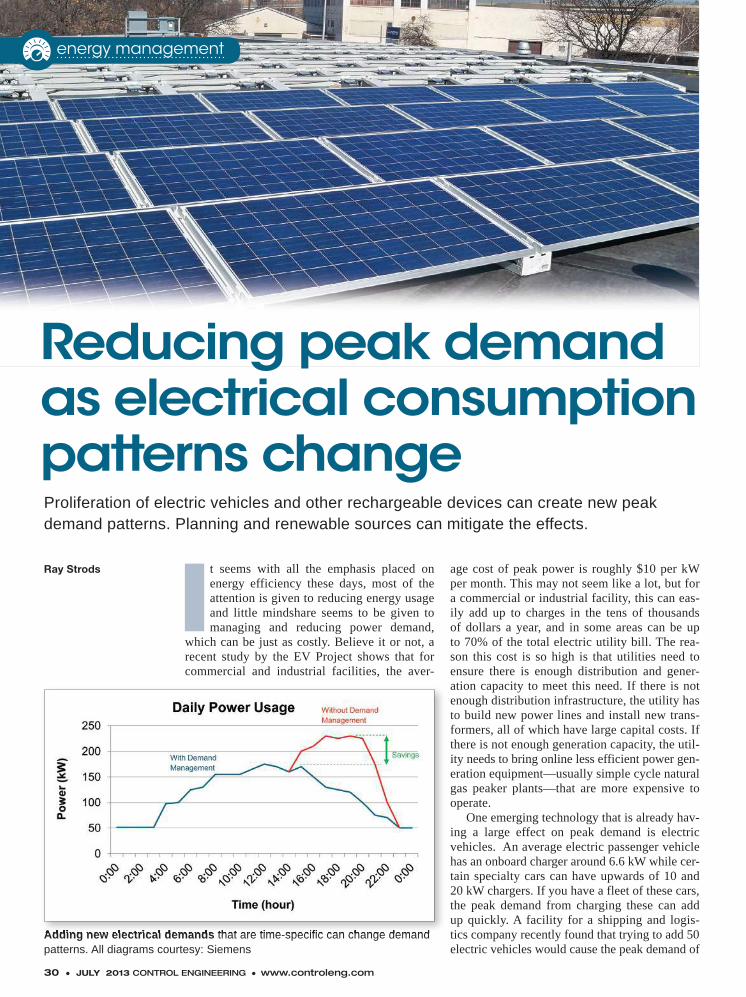
30 ● JULY 2013 CONTROL ENGINEERING ● www.controleng.com
It seems with all the emphasis placed on energy efficiency these days, most of the attention is given to reducing energy usage and little mindshare seems to be given to managing and reducing power demand,
which can be just as costly. Believe it or not, a recent study by the EV Project shows that for commercial and industrial facilities, the aver-
age cost of peak power is roughly $10 per kW per month. This may not seem like a lot, but for a commercial or industrial facility, this can eas-ily add up to charges in the tens of thousands of dollars a year, and in some areas can be up to 70% of the total electric utility bill. The rea-son this cost is so high is that utilities need to ensure there is enough distribution and gener-ation capacity to meet this need. If there is not enough distribution infrastructure, the utility has to build new power lines and install new trans-formers, all of which have large capital costs. If there is not enough generation capacity, the util-ity needs to bring online less efficient power gen-eration equipment—usually simple cycle natural gas peaker plants—that are more expensive to operate.
One emerging technology that is already hav-ing a large effect on peak demand is electric vehicles. An average electric passenger vehicle has an onboard charger around 6.6 kW while cer-tain specialty cars can have upwards of 10 and 20 kW chargers. If you have a fleet of these cars, the peak demand from charging these can add up quickly. A facility for a shipping and logis-tics company recently found that trying to add 50 electric vehicles would cause the peak demand of
Ray Strods
Reducing peak demand as electrical consumption patterns changeProliferation of electric vehicles and other rechargeable devices can create new peak demand patterns. Planning and renewable sources can mitigate the effects.
energy management
Adding new electrical demands that are time-specific can change demand patterns. All diagrams courtesy: SiemensAdding new electrical demands that are time-specific can change demand
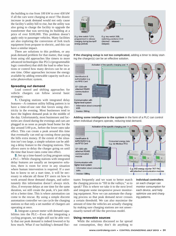
www.controleng.com ● CONTROL ENGINEERING JULY 2013 ● 31
the building to rise from 100 kW to over 430 kW if all the cars were charging at once! The drastic increase in peak demand would not only cause the facility’s utility bill to rise, but the utility was also going to charge the facility to upgrade the transformer that was servicing its building at a price of over $100,000. This problem doesn’t apply only to passenger vehicles. Many facilities are also exploring the conversion of fork truck equipment from propane to electric, and this can have a similar impact.
There are solutions to this problem, or any peak demand problem for that matter, that range from using old approaches like timers to more advanced technologies like PLCs (programmable logic controllers) that shift the load to other loca-tions or control how many devices can be on at one time. Other approaches increase the energy available by adding renewable capacity such as a solar photovoltaic system.
Spreading out demandLoad control and shifting approaches for
vehicle chargers can follow several basic strategies:
1. Charging stations with integrated delay features—A common utility billing pattern is to have a time-of-use rate that favors using elec-tricity in the evening. Most businesses tend to have the highest demand peak in the middle of the day. Unfortunately, most businesses and fac-tories are closed during the evenings and cars are plugged in as soon as people head home for the day around 5:00 p.m., before the lower rates take effect. This can create a peak around this time that eventually can end up costing those paying the bills extra money. If the extent of the situa-tion isn’t too large, a simple solution can be add-ing a delay feature to the charging stations. This allows users to delay the charger going on until the time that lower rates come into effect.
2. Set up a time-based cycling program using a PLC—While charging stations with integrated delay features are usually an inexpensive solu-tion, there is room for error in any situation where human intervention is required. If a user has to know to set a start time, it will be nec-essary to educate all those EV users on how to work around those demand charges, and unfor-tunately this information doesn’t always stick. Also, if everyone delays at one time for the same duration, we still create the peak, it’s just shift-ed to a better time. This is where automation can come to the rescue. By using a simple discrete automation controller we can cycle the charging stations so that only a set number of chargers are operating at once.
3. Integrate a power meter with demand capa-bilities into the PLC—Even after integrating a cycling program, we might still not be able veri-fy that our peak demand is indeed lowered or by how much. What if our building’s demand fluc-
tuates frequently and we want to better match the charging process to “fill in the valleys,” so to speak? This is where we take it to the next level and integrate some inexpensive power monitor-ing equipment. Now we can automate the charg-ing process so that peak demand never crosses a certain threshold. We can also maximize the amount of time the vehicles are actually charging by making sure charging stations are not unnec-essarily turned off like the previous model.
Using renewable sourcesWhile the solutions discussed so far spread
out consumption, they don’t do anything to
If the charging setup is not too complicated, adding a timer to delay start-ing the charger(s) can be an effective solution.
Adding some intelligence to the system in the form of a PLC can control when individual chargers operate, reducing total demand.
Individual controllers on each charger can monitor consumption for each device, and help optimize use and charg-ing patterns.
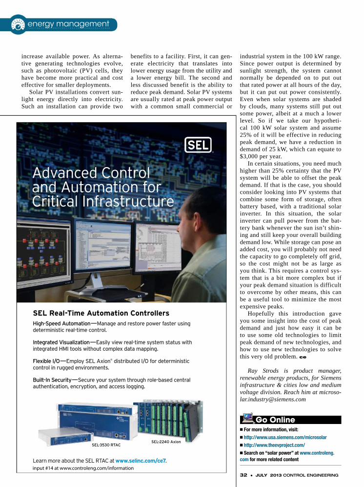
High-Speed Automation—Manage and restore power faster using deterministic real-time control.
Integrated Visualization—Easily view real-time system status with integrated HMI tools without complex data mapping.
Flexible I/O—Employ SEL Axion® distributed I/O for deterministic control in rugged environments.
Built-In Security—Secure your system through role-based central authentication, encryption, and access logging.
SEL Real-Time Automation Controllers
Advanced Control and Automation for Critical Infrastructure
Learn more about the SEL RTAC at www.selinc.com/ce7.
SEL-2240 AxionSEL-3530 RTAC
ControlEng_RTAC_Jul13_A1.indd 1 6/3/13 9:35 AM
input #14 at www.controleng.com/information32 ● JULY 2013 CONTROL ENGINEERING
increase available power. As alterna-tive generating technologies evolve, such as photovoltaic (PV) cells, they have become more practical and cost effective for smaller deployments.
Solar PV installations convert sun-light energy directly into electricity. Such an installation can provide two
benefits to a facility. First, it can gen-erate electricity that translates into lower energy usage from the utility and a lower energy bill. The second and less discussed benefit is the ability to reduce peak demand. Solar PV systems are usually rated at peak power output with a common small commercial or
industrial system in the 100 kW range. Since power output is determined by sunlight strength, the system cannot normally be depended on to put out that rated power at all hours of the day, but it can put out power consistently. Even when solar systems are shaded by clouds, many systems still put out some power, albeit at a much a lower level. So if we take our hypotheti-cal 100 kW solar system and assume 25% of it will be effective in reducing peak demand, we have a reduction in demand of 25 kW, which can equate to $3,000 per year.
In certain situations, you need much higher than 25% certainty that the PV system will be able to offset the peak demand. If that is the case, you should consider looking into PV systems that combine some form of storage, often battery based, with a traditional solar inverter. In this situation, the solar inverter can pull power from the bat-tery bank whenever the sun isn’t shin-ing and still keep your overall building demand low. While storage can pose an added cost, you will probably not need the capacity to go completely off grid, so the cost might not be as large as you think. This requires a control sys-tem that is a bit more complex but if your peak demand situation is difficult to overcome by other means, this can be a useful tool to minimize the most expensive peaks.
Hopefully this introduction gave you some insight into the cost of peak demand and just how easy it can be to use some old technologies to limit peak demand of new technologies, and how to use new technologies to solve this very old problem. ce
Ray Strods is product manager, renewable energy products, for Siemens infrastructure & cities low and medium voltage division. Reach him at [email protected]
n For more information, visit:
n http://www.usa.siemens.com/microsolar
n http://www.theevproject.com/
n Search on “solar power” at www.controleng.com for more related content
Go Online
energy management
Who should enter?If you’re part of a contract engineering fi rm or an engineering division of a larger company that can design and implement computerized control systems for industrial machinery, manufacturing lines, or other automated facilities that produce either a commodity or a fi nished product, Control Engineering urges you to enter its 2014 System Integrator of the Year competition.
What’s in it for the winner?The chosen System Integrator of the Year winner will receive worldwide recognition from Control Engineering. The winner also will be featured as the cover story of the 2014 Automation Integrator Guide, distributed in December 2013.
How will the competition be judged?Control Engineering’s panel of judges will conscientiously evaluate all entries. Three general criteria will be considered for the selection of Control Engineering’s System Integrator of the Year:
• Business skills
• Technical competence
• Customer satisfaction
Control Engineering’s annual
System Integrator of the Year Awards
Tell us how you measure up in these three areas. Get the application at www.controleng.com/SIY
Don’t miss your chance to enter. Entries must be received by Aug. 1, 2013.
Questions? Contact Vance VanDoren,System Integration contributing content specialist forControl Engineering:[email protected](765) 296-7600
ENTRIESARE DUE
AUGUST 1,2013
2 0 1 4 S Y S T E M I N T E G R A T O R O F T H E Y E A R C A L L F O R E N T R I E S
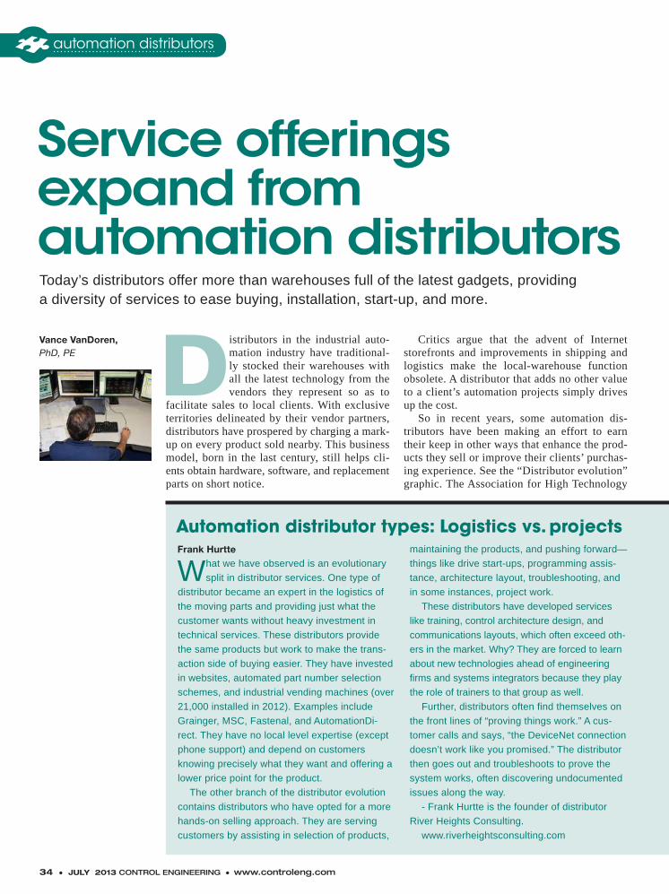
34 ● JULY 2013 CONTROL ENGINEERING ● www.controleng.com
Distributors in the industrial auto-mation industry have traditional-ly stocked their warehouses with all the latest technology from the vendors they represent so as to
facilitate sales to local clients. With exclusive territories delineated by their vendor partners, distributors have prospered by charging a mark-up on every product sold nearby. This business model, born in the last century, still helps cli-ents obtain hardware, software, and replacement parts on short notice.
Critics argue that the advent of Internet storefronts and improvements in shipping and logistics make the local-warehouse function obsolete. A distributor that adds no other value to a client’s automation projects simply drives up the cost.
So in recent years, some automation dis-tributors have been making an effort to earn their keep in other ways that enhance the prod-ucts they sell or improve their clients’ purchas-ing experience. See the “Distributor evolution” graphic. The Association for High Technology
Vance VanDoren, PhD, PE
Service offerings expand from automation distributorsToday’s distributors offer more than warehouses full of the latest gadgets, providing a diversity of services to ease buying, installation, start-up, and more.
automation distributors
What we have observed is an evolutionary
split in distributor services. One type of
distributor became an expert in the logistics of
the moving parts and providing just what the
customer wants without heavy investment in
technical services. These distributors provide
the same products but work to make the trans-
action side of buying easier. They have invested
in websites, automated part number selection
schemes, and industrial vending machines (over
21,000 installed in 2012). Examples include
Grainger, MSC, Fastenal, and AutomationDi-
rect. They have no local level expertise (except
phone support) and depend on customers
knowing precisely what they want and offering a
lower price point for the product.
The other branch of the distributor evolution
contains distributors who have opted for a more
hands-on selling approach. They are serving
customers by assisting in selection of products,
maintaining the products, and pushing forward—
things like drive start-ups, programming assis-
tance, architecture layout, troubleshooting, and
in some instances, project work.
These distributors have developed services
like training, control architecture design, and
communications layouts, which often exceed oth-
ers in the market. Why? They are forced to learn
about new technologies ahead of engineering
firms and systems integrators because they play
the role of trainers to that group as well.
Further, distributors often find themselves on
the front lines of “proving things work.” A cus-
tomer calls and says, “the DeviceNet connection
doesn’t work like you promised.” The distributor
then goes out and troubleshoots to prove the
system works, often discovering undocumented
issues along the way.
- Frank Hurtte is the founder of distributor
River Heights Consulting.
www.riverheightsconsulting.com
Automation distributor types: Logistics vs. projectsFrank Hurtte
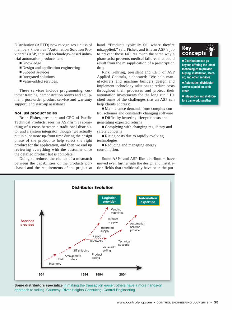
www.controleng.com ● CONTROL ENGINEERING JULY 2013 ● 35
Distribution (AHTD) now recognizes a class of members known as “Automation Solution Pro-viders” (ASP) that sell technology-based indus-trial automation products, and
� Knowledge� Design and application engineering� Support services� Integrated solutions� Value-added services.
These services include programming, cus-tomer training, demonstration rooms and equip-ment, post-order product service and warranty support, and start-up assistance.
Not just product salesBrian Fisher, president and CEO of Pacific
Technical Products, sees his ASP firm as some-thing of a cross between a traditional distribu-tor and a system integrator, though “we actually put in a lot more up-front time during the design phase of the project to help select the right product for the application, and then we end up reviewing everything with the customer once the detailed product list is complete.”
Doing so reduces the chance of a mismatch between the capabilities of the products pur-chased and the requirements of the project at
hand. “Products typically fail where they’re misapplied,” said Fisher, and it is an ASP’s job to prevent those failures much the same way a pharmacist prevents medical failures that could result from the misapplication of a prescription drug.
Rick Gehring, president and CEO of ASP Applied Controls, elaborated: “We help man-ufacturers and machine builders design and implement technology solutions to reduce costs throughout their processes and protect their automation investments for the long run.” He cited some of the challenges that an ASP can help clients address:
� Maintenance demands from complex con-trol schemes and constantly changing software
� Difficulty lowering lifecycle costs and generating expected returns
� Complying with changing regulatory and safety concerns
� Rising costs due to rapidly evolving technologies
� Reducing and managing energy consumption.
Some ASPs and ASP-like distributors have moved even further into the design and installa-tion fields that traditionally have been the pur-
Distributor Evolution
2004199419841954
Servicesprovided Automation
solutionprovider
Vendingmachines
Internetsupplier
Integratedsupply
Supply
Contracts Technicalspecialist
Value addselling
Productselling
JIT shipping
AmalgamateordersCredit
Inventory
Automationexpertise
Logisticsprovider
Some distributors specialize in making the transaction easier; others have a more hands-on approach to selling. Courtesy: River Heights Consulting, Control Engineering
Keyconcepts� Distributors can go beyond offering the latest technologies to provide buying, installation, start-up, and other services.
� Automation distributor services build on each other
� Integrators and distribu-tors can work together
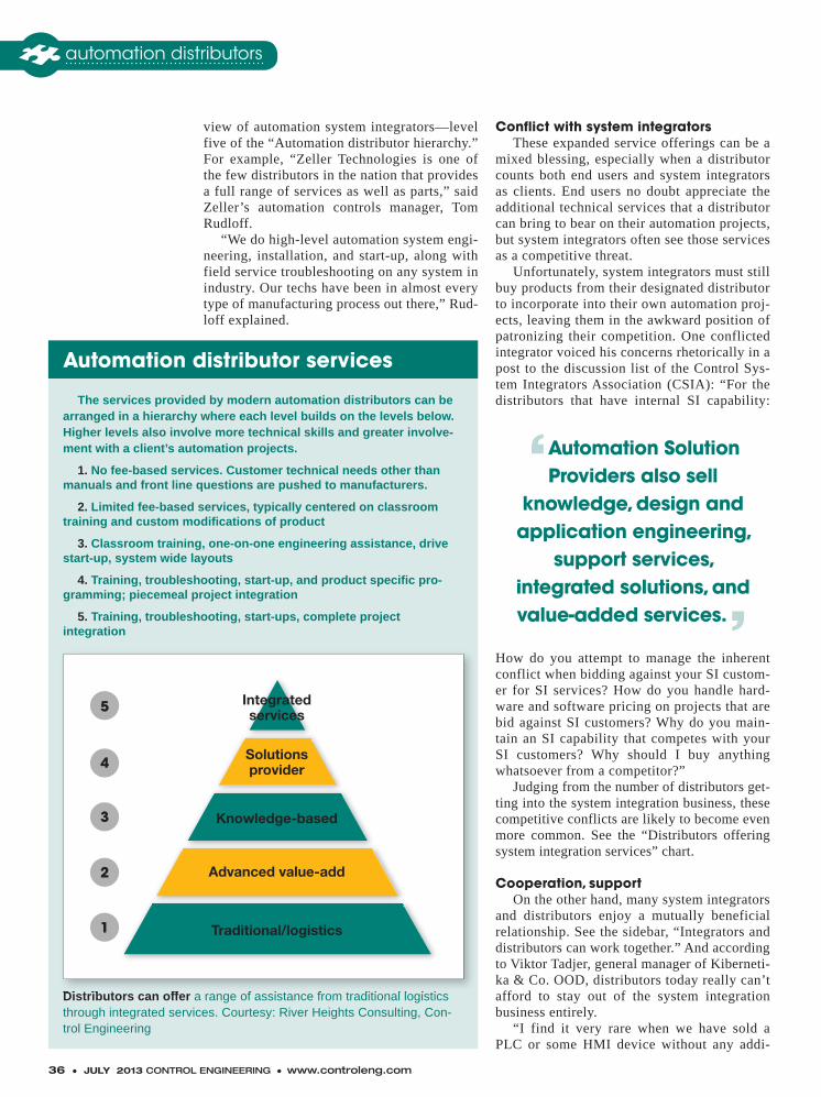
36 ● JULY 2013 CONTROL ENGINEERING ● www.controleng.com
view of automation system integrators—level five of the “Automation distributor hierarchy.” For example, “Zeller Technologies is one of the few distributors in the nation that provides a full range of services as well as parts,” said Zeller’s automation controls manager, Tom Rudloff.
“We do high-level automation system engi-neering, installation, and start-up, along with field service troubleshooting on any system in industry. Our techs have been in almost every type of manufacturing process out there,” Rud-loff explained.
Conflict with system integratorsThese expanded service offerings can be a
mixed blessing, especially when a distributor counts both end users and system integrators as clients. End users no doubt appreciate the additional technical services that a distributor can bring to bear on their automation projects, but system integrators often see those services as a competitive threat.
Unfortunately, system integrators must still buy products from their designated distributor to incorporate into their own automation proj-ects, leaving them in the awkward position of patronizing their competition. One conflicted integrator voiced his concerns rhetorically in a post to the discussion list of the Control Sys-tem Integrators Association (CSIA): “For the distributors that have internal SI capability:
How do you attempt to manage the inherent conflict when bidding against your SI custom-er for SI services? How do you handle hard-ware and software pricing on projects that are bid against SI customers? Why do you main-tain an SI capability that competes with your SI customers? Why should I buy anything whatsoever from a competitor?”
Judging from the number of distributors get-ting into the system integration business, these competitive conflicts are likely to become even more common. See the “Distributors offering system integration services” chart.
Cooperation, supportOn the other hand, many system integrators
and distributors enjoy a mutually beneficial relationship. See the sidebar, “Integrators and distributors can work together.” And according to Viktor Tadjer, general manager of Kiberneti-ka & Co. OOD, distributors today really can’t afford to stay out of the system integration business entirely.
“I find it very rare when we have sold a PLC or some HMI device without any addi-
The services provided by modern automation distributors can be arranged in a hierarchy where each level builds on the levels below. Higher levels also involve more technical skills and greater involve-ment with a client’s automation projects.
1. No fee-based services. Customer technical needs other than manuals and front line questions are pushed to manufacturers.
2. Limited fee-based services, typically centered on classroom training and custom modifications of product
3. Classroom training, one-on-one engineering assistance, drive start-up, system wide layouts
4. Training, troubleshooting, start-up, and product specific pro-gramming; piecemeal project integration
5. Training, troubleshooting, start-ups, complete project integration
Distributors can offer a range of assistance from traditional logistics through integrated services. Courtesy: River Heights Consulting, Con-trol Engineering
Distributors can offer a range of assistance from traditional logistics Distributors can offer a range of assistance from traditional logistics Distributors can offer
5
4
3
2
1
Integratedservices
Solutionsprovider
Knowledge-based
Advanced value-add
Traditional/logistics
Automation distributor services
‘Automation Solution Providers also sell
knowledge, design and application engineering,
support services,integrated solutions, and value-added services.’
automation distributors
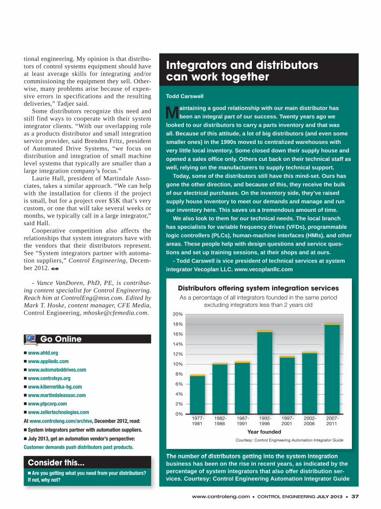
www.controleng.com ● CONTROL ENGINEERING JULY 2013 ● 37
tional engineering. My opinion is that distribu-tors of control systems equipment should have at least average skills for integrating and/or commissioning the equipment they sell. Other-wise, many problems arise because of expen-sive errors in specifications and the resulting deliveries,” Tadjer said.
Some distributors recognize this need and still find ways to cooperate with their system integrator clients. “With our overlapping role as a products distributor and small integration service provider, said Brenden Fritz, president of Automated Drive Systems, “we focus on distribution and integration of small machine level systems that typically are smaller than a large integration company’s focus.”
Laurie Hall, president of Martindale Asso-ciates, takes a similar approach. “We can help with the installation for clients if the project is small, but for a project over $5K that’s very custom, or one that will take several weeks or months, we typically call in a large integrator,” said Hall.
Cooperative competition also affects the relationships that system integrators have with the vendors that their distributors represent. See “System integrators partner with automa-tion suppliers,” Control Engineering, Decem-ber 2012. ce
- Vance VanDoren, PhD, PE, is contribut-ing content specialist for Control Engineering. Reach him at [email protected]. Edited by Mark T. Hoske, content manager, CFE Media, Control Engineering, [email protected].
Consider this...� Are you getting what you need from your distributors? If not, why not?
� www.ahtd.org
� www.appliedc.com
� www.automateddrives.com
� www.controlsys.org
� www.kibernetika-bg.com
� www.martindaleassoc.com
� www.ptpcorp.com
� www.zellertechnologies.com
At www.controleng.com/archive, December 2012, read:
� System integrators partner with automation suppliers.
� July 2013, get an automation vendor’s perspective:
Customer demands push distributors past products.
Go Online
Integrators and distributorscan work together
Todd Carswell
Maintaining a good relationship with our main distributor has
been an integral part of our success. Twenty years ago we
looked to our distributors to carry a parts inventory and that was
all. Because of this attitude, a lot of big distributors (and even some
smaller ones) in the 1990s moved to centralized warehouses with
very little local inventory. Some closed down their supply house and
opened a sales office only. Others cut back on their technical staff as
well, relying on the manufacturers to supply technical support.
Today, some of the distributors still have this mind-set. Ours has
gone the other direction, and because of this, they receive the bulk
of our electrical purchases. On the inventory side, they’ve raised
supply house inventory to meet our demands and manage and run
our inventory here. This saves us a tremendous amount of time.
We also look to them for our technical needs. The local branch
has specialists for variable frequency drives (VFDs), programmable
logic controllers (PLCs), human-machine interfaces (HMIs), and other
areas. These people help with design questions and service ques-
tions and set up training sessions, at their shops and at ours.
- Todd Carswell is vice president of technical services at system
integrator Vecoplan LLC. www.vecoplanllc.com
The number of distributors getting into the system integration business has been on the rise in recent years, as indicated by the percentage of system integrators that also offer distribution ser-vices. Courtesy: Control Engineering Automation Integrator Guide
The number of distributors getting into the system integration
Distributors offering system integration servicesAs a percentage of all integrators founded in the same period
excluding integrators less than 2 years old
Year foundedCourtesy: Control Engineering Automation Integrator Guide
20%
18%
16%
14%
12%
10%
8%
6%
4%
2%
0%2007-2011
2002-2006
1997-2001
1992-1996
1987-1991
1982-1986
1977-1981

P1 ● JULY 2013 CONTROL ENGINEERING ● www.controleng.com
inside process
Temperature variances in process industries can have significant impact on profits, safety, and qual-ity. A variety of industries and appli-cations are affected, including oil
and gas, power, refining, petrochemical, phar-maceutical, and more. Monitoring temperature accurately is dependent upon several factors, including selecting the right sensor for the spe-cific application and process.
Two of the most common temperature mea-surement devices are resistance temperature detectors (RTDs) and thermocouples (TCs). The technology behind them is different, each having its own benefits that drive appropriate selection.
An RTD uses the principle that the electri-cal resistance of a metal increases as tempera-ture increases—a phenomenon known as thermal resistivity.
In comparison, a TC is a closed-circuit ther-moelectric temperature sensing device consist-ing of two wires of dissimilar metals joined at both ends. A voltage is created when the temper-ature at one end of a wire or junction differs from the temperature at the other end. This phenom-enon is known as the Seebeck effect. That volt-age depends on the particular metal as well as the temperature difference. Comparing the differ-ent voltages created by the different metals is the basis for TC temperature measurements.
Comparing the differences RTDs are constructed of a resistive materi-
al with leads attached and usually placed into a protective sheath. The resistive material may be platinum, copper, or nickel; the most common is platinum because of its high accuracy, excel-lent repeatability, and exceptional linearity over
Ashleigh Hayes
Temperature sensors:
Make the right choice, RTD vs. TCWhen you need a temperature measurement, one of the most basic decisions is choosing which kind of sensor to deploy. The application should guide your decision.
There is no single answer that works in every situation. There are tradeoffs in performance characteristics that need to be considered carefully when making a selection. Diagrams cour-tesy: Emerson Process Management.
Keyconcepts� Measuring temperature is a basic requirement in virtually any process man-ufacturing environment.
� Two sensor technologies support the majority of installations.
� Selecting between the two main approaches depends on specific pro-cess requirements and conditions.
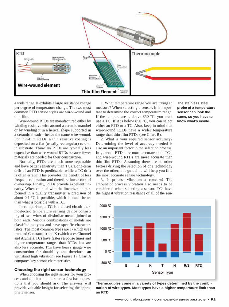
www.controleng.com ● CONTROL ENGINEERING JULY 2013 ● P2
a wide range. It exhibits a large resistance change per degree of temperature change. The two most common RTD sensor styles are wire-wound and thin-film.
Wire-wound RTDs are manufactured either by winding resistive wire around a ceramic mandrel or by winding it in a helical shape supported in a ceramic sheath—hence the name wire-wound. For thin-film RTDs, a thin resistive coating is deposited on a flat (usually rectangular) ceram-ic substrate. Thin-film RTDs are typically less expensive than wire-wound RTDs because fewer materials are needed for their construction.
Normally, RTDs are much more repeatable and have better sensitivity than TCs. Long-term drift of an RTD is predictable, while a TC drift is often erratic. This provides the benefit of less frequent calibration and therefore lower cost of ownership. Finally, RTDs provide excellent lin-earity. When coupled with the linearization per-formed in a quality transmitter, a precision of about 0.1 °C is possible, which is much better than what is possible with a TC.
In comparison, a TC is a closed-circuit ther-moelectric temperature sensing device consist-ing of two wires of dissimilar metals joined at both ends. Various combinations of metals are classified as types and have specific character-istics. The most common types are J (which uses iron and Constantan) and K (which uses Chromel and Alumel). TCs have faster response times and higher temperature ranges than RTDs, but are also less accurate. TCs have heavy gauge wire construction for durability and therefore can withstand high vibration (see Figure 1). Chart A compares key sensor characteristics.
Choosing the right sensor technologyWhen choosing the right sensor for your pro-
cess and application, there are a few basic ques-tions that you should ask. The answers will provide valuable insight for selecting the appro-priate sensor.
1. What temperature range you are trying to measure? When selecting a sensor, it is impor-tant to determine the correct temperature range. If the temperature is above 850 °C, you must use a TC. If it is below 850 °C, you can select either an RTD or a TC. Also, keep in mind that wire-wound RTDs have a wider temperature range than thin-film RTDs (see Chart B).
2. What is your required sensor accuracy? Determining the level of accuracy needed is also an important factor in the selection process. In general, RTDs are more accurate than TCs, and wire-wound RTDs are more accurate than thin-film RTDs. Assuming there are no other factors driving the selection of one technology over the other, this guideline will help you find the most accurate sensor technology.
3. Is process vibration a concern? The amount of process vibration also needs to be considered when selecting a sensor. TCs have the highest vibration resistance of all of the sen-
The stainless steel probe of a temperature sensor can look the same, so you have to know what’s inside..
Thermcouples come in a variety of types determined by the combi-nation of wire types. Most types have a higher temperature limit than an RTD.

1-800-343-1001 • www.predig.com/modbus
View A New Dimensionof Display Possibilities
Take Advantage of Your Modbus SignalBy using the Modbus signal from your existing multivariable level transmitters you will unleash a whole new dimension of display possibilities. Paired with a new Precision Digital Modbus Scanner you can display multiple variables including level, interface level, density, temperature and more.
Why Modbus Scanners? > Scan up to 16 PVs > Easy instrallation & setup > Display level in feet & inches* > SafeTouch® thru-glass buttons* > Display PV and tag name > 4-20 mA retransmission
* Available on select meters
PRECISION DIGITAL CORPORATION Since 1974
Call us to discuss your application and receive aFREE 4GB USB DRIVE
DENSITY
LEVEL
VOLUME
INTERFACE LEVEL
TEMPERATURE
Modbus
MORE
input #15 at www.controleng.com/information P3 ● JULY 2013 CONTROL ENGINEERING
sor technologies. If you have a known high vibration, TCs will give you the highest reliability. Thin-film RTDs are also resistant to vibration; however, they are not as robust. Wire-wound RTDs should not be used in high-vibration environments.
The right choice brings the right results
The overall key to success is ask-ing basic questions and matching up the information with the right sensor for your applications and process. An example would be adding a tempera-
ture measurement to a pipeline where the measurement is under varying condi-tions with constant vibration and a pro-cess temperature variance of 200 to 300 °C. The goal is to have the best possible accuracy despite these challenges.
To determine what type of sensor to use, first consider the differences between TCs and RTDs. The temper-ature range makes both sensor tech-nologies feasible for this application. TCs are known for their higher vibra-tion tolerance, so at a first glance TCs would appear to be a good option. However, in this specific instance the measurement requires the best possi-
ble accuracy. The right choice for this application would be a thin-film RTD. Thin-film RTDs are known for their higher tolerance to vibration than wire-wound RTDs, and will provide a high-er accuracy than a TC.
A second example would be the tem-perature in a reactor that ranges between 550 and 900 °C with little vibration. The goal is to gain accuracy within ±5 °C. RTDs provide consistent accurate mea-surements, especially in environments with little vibration. However, don’t for-get the temperature range. RTDs typically should not be used above 850 °C. Since the process temperature can range up to 900 °C, a TC would be selected. Sen-sors are more susceptible to failure and inaccurate measurements when used in improper temperature ranges. That is why it is critical to select the correct sensor. ce
Ashley Hayes is a marketing engineer for Emerson Process Management.
inside process
n www.rosemount.com/TempGuide
Go Online
‘The overall key to success is asking basic questions and matching up the information with
the right sensor for your applications and
process.’
www.controleng.com ● CONTROL ENGINEERING JULY 2013 ● P4
Effective model-based control strat-egy depends on creating an accu-rate model of the process. Without this most basic capability, the pro-cess will not run properly. So when
faults arise, it is important to determine if they are actual operational problems or an incorrect modeling assumption. This overview describes a general methodology for creating optimal mod-el-based process fault analyzers. It is called MOME (method of minimal evidence). MOME is a diagnostic strategy based upon the evalua-tion of engineering models describing normal operation of the target process system with sen-sor data. This methodology uses the minimum amount of diagnostic evidence necessary to dis-criminate uniquely between an invalid modeling assumption variable (e.g., an assumption which assumes the absence of a particular process fault situation) and all other valid modeling assump-tion variables.
Moreover, it ensures that the resulting fault analyzer will always perform competently and optimizes the diagnostic sensitivity and reso-lution of its diagnoses. Diagnostic knowledge bases created with this methodology are also conducive for diagnosing many multiple fault situations, for determining the strategic place-ment of process sensors to facilitate fault analy-sis, and for determining the shrewd distribution of fault analyzers within large processing plants. It has been demonstrated to be competent in both an adipic acid plant formerly owned and operated by DuPont in Victoria, Texas, and an electrolyt-ic persulfate plant owned and operated by FMC in Tonawanda, New York. A simplified schematic of the two FMC processes (ESP - sodium persul-fate and LAP - ammonium persulfate) is illustrat-ed in Figure 1.
Effective operation of these persulfate pro-cesses requires extremely strict control of the solution chemistry. Maintaining tight windows
of the strengths and pH across all the various cat-ion and anion species throughout is thus critical. This in turn requires highly accurate and reli-able measurements of these variables and meth-ods for verifying those accuracies. Consequently, automated model-based process fault analysis provides a useful tool for guaranteeing which of these measurements are currently correct and immediately flagging those which are not. This automated detection and alerting capability allows FMC to operate its DCSs in full auto-pilot mode more frequently.
While MOME can be set up using a home-grown system, it has been converted into a pat-ented fuzzy logic reasoning algorithm and is now fully automated in a program called FAL-CONEER IV. Once this platform became avail-able, FMC found that converting its original hand-compiled FMC ESP fault analyzer into the format necessary for automatically gener-ating the diagnostic logic required only coding the existing 30 primary models and performance equations describing that process. Creating, cod-ing, and analyzing more than 30 primary mod-els and five performance equations for the FMC LAP process required approximately two person-weeks of effort in order to derive a fully func-tional and validated process fault analyzer. FMC has independently documented some of the ben-efits derived from these two applications. All FALCONEER IV applications can diagnose all single fault situations at all possible levels of diagnostic resolution and all non-interactive and also almost all possible pairs of interactive mul-tiple fault situations.
MOME diagnostic strategyModel-based reasoning is a highly system-
atic and powerful means for deriving plausible hypotheses as to the causes of abnormal process behavior. The first step in developing competent model-based fault analyzers is to derive a set of as many linearly independent models of normal process operation as possible. These should accu-rately describe the behavior of the target process
Richard J. Fickelscherer, PhD, PE,Daniel L. Chester, PhD
Diagnosing faultsin engineering modelsMethod of minimal evidence techniques help identify invalid modeling assumption variables.
inside process
Keyconcepts� An effective model-based process control strategy depends on having an effective process model.
� Analyzing faults to the root cause is using this analysis strategy can yield a more reliable result with less information required.
� Additional information on this technique is available online.
input #16 at www.controleng.com/information
system during its malfunction-free (i.e., nor-mal) operation. These models include the normal operating characteristics of the process system components, the functional relationships between those components, the process control strategy, and the underlying fundamental conservation, thermodynamic, and physio-chemical principles. The set of modeling assumptions required to derive these models defines the domain in which they predict normal process behavior.
The diagnostic evidence generated by eval-uating these models with actual process data is then compared with the expected patterns of the model behavior during various possible fault sit-uations, i.e., the SV&PFA (sensor validation and proactive fault analysis) diagnostic rules, which can logically discriminate between the various possible process operating events within the fault analyzer’s intended scope. The specific patterns of diagnostic evidence used for this discrimi-nation depend entirely upon the specific mod-el-based diagnostic strategy actually employed. Model-based fault analyzers in a nutshell are thus computer programs that determine which of their SV&PFA diagnostic rules most close-ly match currently observed process behavior.
inside process
Learn more on the basics ofmodel-based control
Model-based control is one of the main approaches for a larger advanced pro-cess control (APC) strategy. Plant operators turn to this in situations where
conventional regulatory control might not run a process optimally. For example, where a process runs erratically, it’s difficult to run close to the upper limit in an effort to maximize production without breaking through the limit. When the line is more stable, it’s possible to run closer to the edge.
Building a process model begins with understanding and quantifying what is actually happening to the feedstocks as they are turned into final products. This
includes chemical reactions, energy balance, reaction times, and so on. As this story dis-cusses, if there are problems keeping the pro-cess under control while running model-based control, it is important to determine if there is a problem with the process itself, or if one of the assumptions of the model is incorrect.
If you want to know more about APC in general, here are articles you can find at www.
controleng.com/archives that can help you understand the concepts better:
Do-it-yourself model-based control, March 2013Advanced process control in electric utilities: How model-based control
can optimize overall steam cycle and burner management, March 2012Controlling Diesel hydrotreaters: How APC solved a chronic and burden-
some operating problem on a Diesel hydrotreater, January 2010Driving plant optimization with APC, November 2009
includes chemical reactions, energy balance, reaction times, and so on. As this story dis-cusses, if there are problems keeping the pro-cess under control while running model-based control, it is important to determine if there is a problem with the process itself, or if one of the assumptions of the model is incorrect.
general, here are articles you can find at www.controleng.com/archives that can help you understand the concepts better:

YOU CAN DO THAT
Smart, modern safety system designed for the life of your plant.Emerson’s smart safety instrumented system takes a modern approach to monitoring your plant’ssafety status and diagnosing the health of the entire safety loop–to perform on demand–so you
can be sure your system will shut down when required, and keep running safely when a componentfails. Electronic marshalling in DeltaV SIS gives you the flexibility to implement safety functions easily,safely, while eliminating time consuming tasks, re-work and re-design headaches associated withtraditional marshalling. That’s modern. That’s peace of mind. Find out more at: www.DeltaVSIS.com
Our safety system can sit idle for months.I need assurance that it will work when itshould and not shut us down when itshouldn’t. Any time. Every time.
The Emerson logo is a trademark and a service mark of Emerson Electric Co. © 2013 Emerson Electric Co.
input #17 at www.controleng.com/information
EASY INSTALLATION• No holes in tanks or pipes • Away from sensitive processes
VERSATILE• One size adjusts to motors, from
small up to 150hp
• Works on 3 phase, fi xed or variable frequency, DC and single phase power
SENSITIVE• 10 times more sensitive than
just sensing amps
CONVENIENT OUTPUTS• For meters, controllers, computers
4-20 milliamps 0-10 volts
MONITOR VISCOSITY SIMPLY
CALL NOW FOR YOUR FREE 30-DAY TRIAL 888-600-3247
SENSE MIXER MOTOR HORSEPOWER WITH UNIVERSAL POWER CELL
24
0
22
20
18
14
12
10
8
6
4
2
16
POWER DECREASE SHOWS BATCH
IS DONE
BEGIN HIGHSPEED MIX
ADD LIQUIDLOW SPEED
DRY MIXHIGH SPEED
BATCH 1 BATCH 2 BATCH 3
POWER SENSOR
MIXER MOTOR
• Power changes refl ect viscosity changes• Good batches will fi t the normal “profi le” for
that product
PROFILING A PROCESS
WWW.LOADCONTROLS.COM
input #18 at www.controleng.com/information
Their understanding of process fault situations is thus completely determined by their underlying models of normal operation and the consequent SV&PFA diagnostic rules for identifying those fault situations.
However, the SV&PFA diagnostic rules we utilize are automatically generated by our MOME fuzzy logic algorithm compiler and are thus always logically correct. Consequent-ly, since the diagnostic evidence used by those diagnostic rules is determined directly from eval-uating its underlying process models, the fault analyzer’s performance is inherently circum-scribed completely by understanding normal pro-cess behavior represented within those models.
The main advantageThe MOME diagnostic strategy’s chief advan-
tage for developing optimal diagnostic rules aris-es from its choice of patterns of possible satisfied and violated process model residuals used to identify plausible fault hypotheses. Only those models considered relevant for each potential process fault are contained in the associated diagnostic rules. MOME consequently identi-fies all possible assumption variable deviations
consistent with the current pattern of diagnostic evidence generated by the most recently sampled process sensor data. Perfect resolution between different process fault hypotheses is thus not always possible or is possible only at larger mag-nitudes of the specified fault (i.e., at a magnitude sufficient enough to violate all so affected rele-vant model residuals).
This is the classic trade-off between time-ly fault detection and correctly identifying the underlying fault(s). Trading lower diagnostic resolution for higher diagnostic sensitivity allows the fault analyzer to narrow down the potential process faults that could be occurring currently into a reasonable number of plausible explana-tions for the current process state that can then be further checked out by the process operator to determine the actual fault present. This direct-ly flags potential incipient fault situations soon-er rather than waiting until the fault’s magnitude is severe enough to allow unique classification. This is why the methodology is called the meth-od of minimal evidence: all plausible fault situ-ations are diagnosed whenever even just one of the linearly independent set’s model residuals indicates abnormal process operation.
inside process
‘Trading lower diagnostic
resolution for higher diagnostic sensitivity allows the fault analyzer to narrow down
the potential process faults
that could be occurring currently into a reasonable
number of plausible
explanations.’
THE DIFFERENCE BETWEEN OPERATION
�nly Winsted control room consoles combine the con�guration �e�ibility you need with the robust performance you demand. From modular to custom, Winsted consoles offer an array of options and modi�cations that optimi�e aesthetics, function and ergonomics. Bring your ultimate control environment to life with our FREE WELS 3D console design software. Try it now: winsted.com/wels
WEB: winsted.com • EMAIL: [email protected] • TEL: 800.447.2257 • FAX: 800.421.3839
AND CONTROL
input #19 at www.controleng.com/information
Logical deductionsMOME employs model-based reasoning to
deduce the cause or causes of abnormal process behavior. It does so with the least amount of diagnostic evidence necessary to diagnose the various possible fault situations uniquely. More-over, the resulting fault analyzer always makes competent diagnoses at the best resolution and highest sensitivity possible for the given magni-tude of the fault(s) occurring.
A key feature of this method is in the way in which the various patterns of diagnostic evi-dence are selected. This selection fully uti-lizes all of the information contained within the available diagnostic evidence, especially the estimates of the fault magnitudes of lin-ear assumption variable deviations inherent in the violated model residuals. The strategy fol-lowed in this selection relies upon default rea-soning: all but one of the fault hypotheses (if perfect resolution is possible) being supported by some of the diagnostic evidence contained within a given pattern of diagnostic evidence is systematically shown to be implausible by some of the other evidence also contained within that pattern.
Thus, by default, the remaining fault hypoth-esis is the only plausible explanation of the full pattern of relevant diagnostic evidence. Using default reasoning in this manner allows this diagnostic strategy to base each fault diagnosis upon the least amount of diagnostic evidence necessary for that proper diagnosis. This direct-ly allows many other potential multiple fault situations to be properly diagnosed.
The various issues described throughout this treatment and its companion online article are discussed in much greater detail and in “Opti-mal Automated Process Fault Analysis,” Rich-ard J. Fickelscherer and Daniel L. Chester, © John Wiley & Sons, Inc., 2013. This material is reproduced with permission of John Wiley & Sons, Inc. http://www.wiley.com/WileyCDA/ ce
Dr. Richard J. Fickelscherer, PE, is a partner at Falconeer Technologies, LLC, Williamsville, N.Y. Reach him at [email protected]. Dr. Daniel L. Chester is currently the associate chair of the department of computer and infor-mation sciences at the University of Delaware. He is also a co-founder of Falconeer Technolo-gies, LLC. Reach him at [email protected].
n The online version of this story contains a link to a more detailed discussion including more detail on the supporting techniques and equations. Read it at www.controleng.com
n http://falconeertech.com/
n www.wiley.com
Go Online
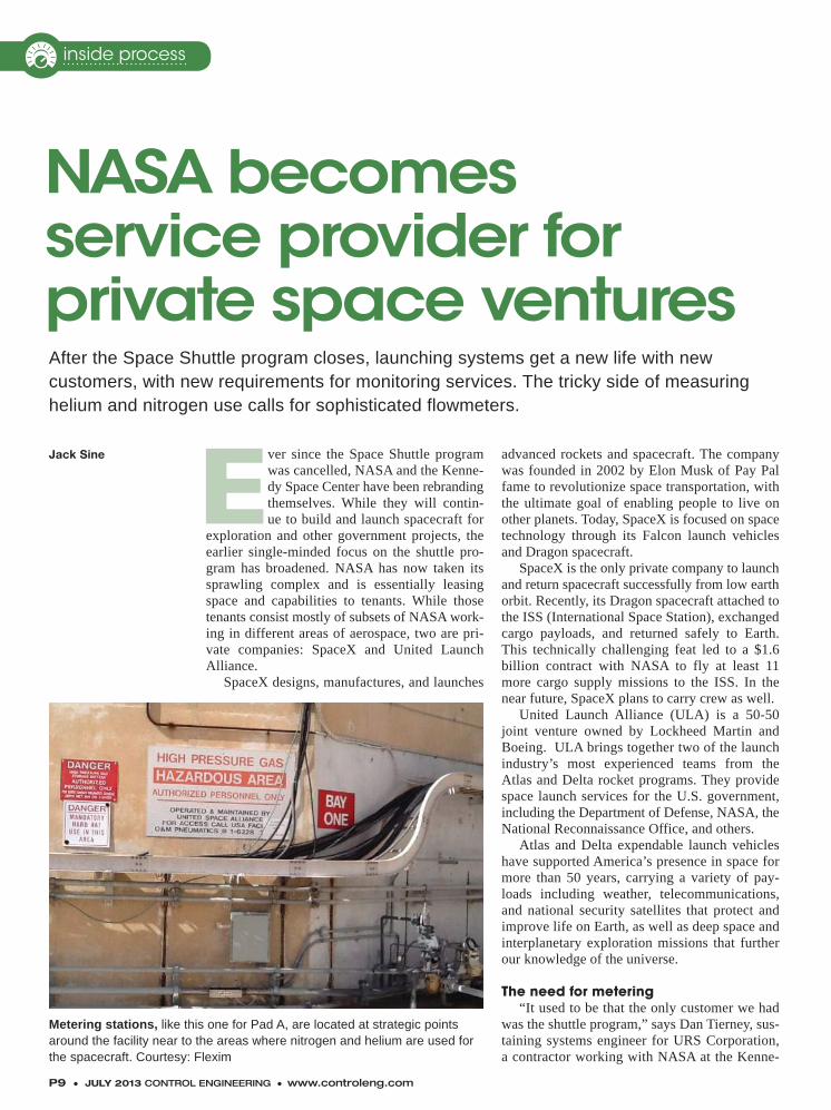
P9 ● JULY 2013 CONTROL ENGINEERING ● www.controleng.com
Ever since the Space Shuttle program was cancelled, NASA and the Kenne-dy Space Center have been rebranding themselves. While they will contin-ue to build and launch spacecraft for
exploration and other government projects, the earlier single-minded focus on the shuttle pro-gram has broadened. NASA has now taken its sprawling complex and is essentially leasing space and capabilities to tenants. While those tenants consist mostly of subsets of NASA work-ing in different areas of aerospace, two are pri-vate companies: SpaceX and United Launch Alliance.
SpaceX designs, manufactures, and launches
advanced rockets and spacecraft. The company was founded in 2002 by Elon Musk of Pay Pal fame to revolutionize space transportation, with the ultimate goal of enabling people to live on other planets. Today, SpaceX is focused on space technology through its Falcon launch vehicles and Dragon spacecraft.
SpaceX is the only private company to launch and return spacecraft successfully from low earth orbit. Recently, its Dragon spacecraft attached to the ISS (International Space Station), exchanged cargo payloads, and returned safely to Earth. This technically challenging feat led to a $1.6 billion contract with NASA to fly at least 11 more cargo supply missions to the ISS. In the near future, SpaceX plans to carry crew as well.
United Launch Alliance (ULA) is a 50-50 joint venture owned by Lockheed Martin and Boeing. ULA brings together two of the launch industry’s most experienced teams from the Atlas and Delta rocket programs. They provide space launch services for the U.S. government, including the Department of Defense, NASA, the National Reconnaissance Office, and others.
Atlas and Delta expendable launch vehicles have supported America’s presence in space for more than 50 years, carrying a variety of pay-loads including weather, telecommunications, and national security satellites that protect and improve life on Earth, as well as deep space and interplanetary exploration missions that further our knowledge of the universe.
The need for metering“It used to be that the only customer we had
was the shuttle program,” says Dan Tierney, sus-taining systems engineer for URS Corporation, a contractor working with NASA at the Kenne-
Jack Sine
NASA becomes service provider for private space venturesAfter the Space Shuttle program closes, launching systems get a new life with new customers, with new requirements for monitoring services. The tricky side of measuring helium and nitrogen use calls for sophisticated flowmeters.
Metering stations, like this one for Pad A, are located at strategic points around the facility near to the areas where nitrogen and helium are used for the spacecraft. Courtesy: Flexim
inside process
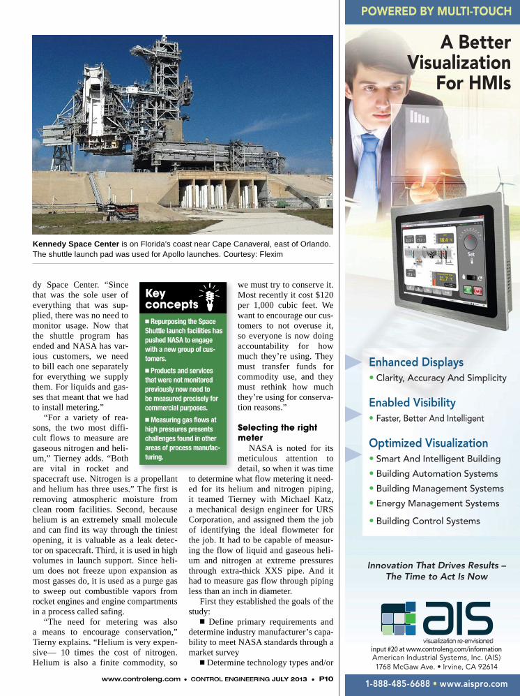
POWERED BY MULTI-TOUCH
A Better Visualization
For HMIs
Enhanced Displays• Clarity, Accuracy And Simplicity
Enabled Visibility• Faster, Better And Intelligent
Optimized Visualization• Smart And Intelligent Building
• Building Automation Systems
• Building Management Systems
• Energy Management Systems
• Building Control Systems
Innovation That Drives Results – The Time to Act Is Now
American Industrial Systems, Inc. (AIS)1768 McGaw Ave. • Irvine, CA 92614
1-888-485-6688 • www.aispro.com
input #20 at www.controleng.com/information
www.controleng.com ● CONTROL ENGINEERING JULY 2013 ● P10
dy Space Center. “Since that was the sole user of everything that was sup-plied, there was no need to monitor usage. Now that the shuttle program has ended and NASA has var-ious customers, we need to bill each one separately for everything we supply them. For liquids and gas-ses that meant that we had to install metering.”
“For a variety of rea-sons, the two most diffi-cult flows to measure are gaseous nitrogen and heli-um,” Tierney adds. “Both are vital in rocket and spacecraft use. Nitrogen is a propellant and helium has three uses.” The first is removing atmospheric moisture from clean room facilities. Second, because helium is an extremely small molecule and can find its way through the tiniest opening, it is valuable as a leak detec-tor on spacecraft. Third, it is used in high volumes in launch support. Since heli-um does not freeze upon expansion as most gasses do, it is used as a purge gas to sweep out combustible vapors from rocket engines and engine compartments in a process called safing.
“The need for metering was also a means to encourage conservation,” Tierny explains. “Helium is very expen-sive— 10 times the cost of nitrogen. Helium is also a finite commodity, so
we must try to conserve it. Most recently it cost $120 per 1,000 cubic feet. We want to encourage our cus-tomers to not overuse it, so everyone is now doing accountability for how much they’re using. They must transfer funds for commodity use, and they must rethink how much they’re using for conserva-tion reasons.”
Selecting the right meter
NASA is noted for its meticulous attention to detail, so when it was time
to determine what flow metering it need-ed for its helium and nitrogen piping, it teamed Tierney with Michael Katz, a mechanical design engineer for URS Corporation, and assigned them the job of identifying the ideal flowmeter for the job. It had to be capable of measur-ing the flow of liquid and gaseous heli-um and nitrogen at extreme pressures through extra-thick XXS pipe. And it had to measure gas flow through piping less than an inch in diameter.
First they established the goals of the study:
� Define primary requirements and determine industry manufacturer’s capa-bility to meet NASA standards through a market survey
� Determine technology types and/or
Kennedy Space Center is on Florida’s coast near Cape Canaveral, east of Orlando. The shuttle launch pad was used for Apollo launches. Courtesy: Flexim
Keyconcepts� Repurposing the Space Shuttle launch facilities has pushed NASA to engage with a new group of cus-tomers.
� Products and services that were not monitored previously now need to be measured precisely for commercial purposes.
� Measuring gas flows at high pressures presents challenges found in other areas of process manufac-turing.
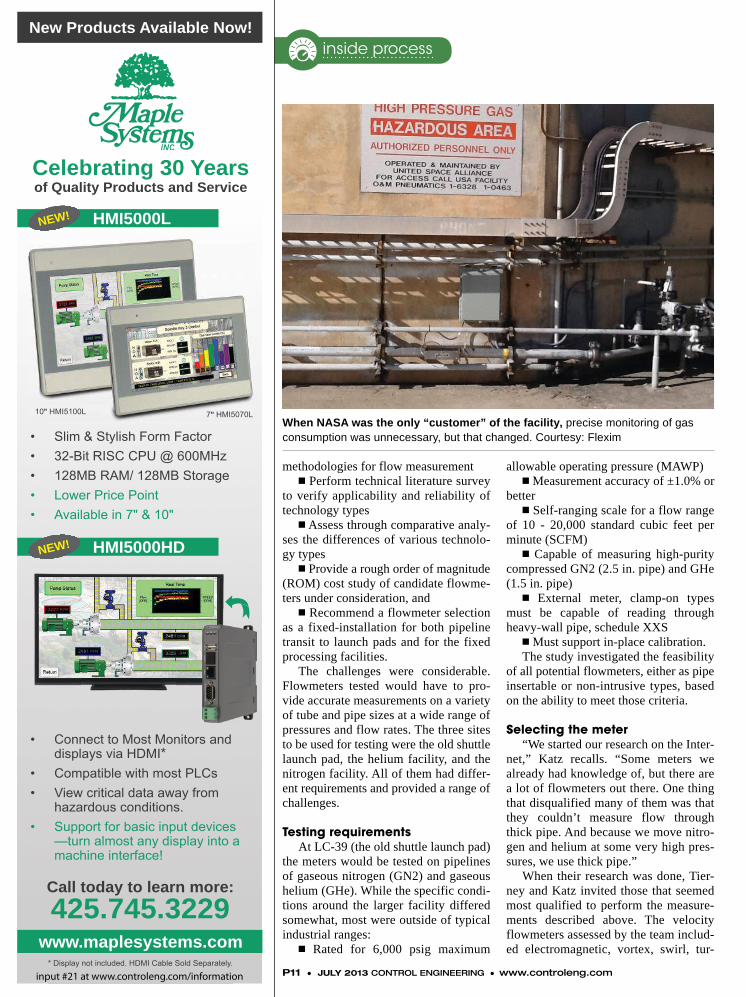
• Slim & Stylish Form Factor• 32-Bit RISC CPU @ 600MHz• 128MB RAM/ 128MB Storage• Lower Price Point• Available in 7" & 10"
• Connect to Most Monitors and displays via HDMI*
• Compatible with most PLCs• View critical data away from
hazardous conditions.• Support for basic input devices
—turn almost any display into a machine interface!
Celebrating 30 Yearsof Quality Products and Service
New Products Available Now!
HMI5000L
HMI5000HD
www.maplesystems.com
Call today to learn more:
425.745.3229
* Display not included. HDMI Cable Sold Separately.
NEW!
NEW!
10" HMI5100L 7" HMI5070L
inside process
P11 ● JULY 2013 CONTROL ENGINEERING ● www.controleng.com
methodologies for flow measurementn Perform technical literature survey
to verify applicability and reliability of technology types
n Assess through comparative analy-ses the differences of various technolo-gy types
n Provide a rough order of magnitude (ROM) cost study of candidate flowme-ters under consideration, and
n Recommend a flowmeter selection as a fixed-installation for both pipeline transit to launch pads and for the fixed processing facilities.
The challenges were considerable. Flowmeters tested would have to pro-vide accurate measurements on a variety of tube and pipe sizes at a wide range of pressures and flow rates. The three sites to be used for testing were the old shuttle launch pad, the helium facility, and the nitrogen facility. All of them had differ-ent requirements and provided a range of challenges.
Testing requirementsAt LC-39 (the old shuttle launch pad)
the meters would be tested on pipelines of gaseous nitrogen (GN2) and gaseous helium (GHe). While the specific condi-tions around the larger facility differed somewhat, most were outside of typical industrial ranges:
n Rated for 6,000 psig maximum
allowable operating pressure (MAWP)n Measurement accuracy of ±1.0% or
bettern Self-ranging scale for a flow range
of 10 - 20,000 standard cubic feet per minute (SCFM)
n Capable of measuring high-purity compressed GN2 (2.5 in. pipe) and GHe (1.5 in. pipe)
n External meter, clamp-on types must be capable of reading through heavy-wall pipe, schedule XXS
n Must support in-place calibration.The study investigated the feasibility
of all potential flowmeters, either as pipe insertable or non-intrusive types, based on the ability to meet those criteria.
Selecting the meter“We started our research on the Inter-
net,” Katz recalls. “Some meters we already had knowledge of, but there are a lot of flowmeters out there. One thing that disqualified many of them was that they couldn’t measure flow through thick pipe. And because we move nitro-gen and helium at some very high pres-sures, we use thick pipe.”
When their research was done, Tier-ney and Katz invited those that seemed most qualified to perform the measure-ments described above. The velocity flowmeters assessed by the team includ-ed electromagnetic, vortex, swirl, tur-
When NASA was the only “customer” of the facility, precise monitoring of gas consumption was unnecessary, but that changed. Courtesy: Flexim
input #21 at www.controleng.com/information
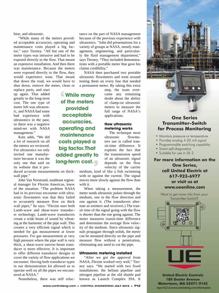
One Series Transmitter-Switch
for Process Monitoring• Monitors pressure or temperature • Provides analog 4-20 mA signal• Programmable switching capability• Smart self-diagnostics• Suitable for use in SIL 2
United Electric Controls180 Dexter Avenue
Watertown, MA 02471-9143
For more information on the One Series,
call United Electric at 617-923-6977 or visit us at
www.ueonline.com
Want to get more info from your Transmitter-Switch?
input #22 at www.controleng.com/information
bine, and ultrasonic. “While many of the meters provid-
ed acceptable accuracies, operating and maintenance costs played a big fac-tor,” says Tierney. “All but one of the meter types was intrusive and had to be exposed directly to the flow. That meant an expensive installation. And then there was maintenance. Because the meters were exposed directly to the flow, they would experience wear. That meant that down the road, we would have to shut down, remove the meter, clean or replace parts, and start up again. That added greatly to the long-term cost. The one type of meter left was ultrason-ic, and NASA had some bad experience with ultrasonics in the past, so there was a negative mind-set with NASA management.”
Katz adds, “We did a lot of research on all the meters we reviewed. For ultrasonics we only invited one manufac-turer because it was the only one that said on its website that it pro-duced accurate measurements on thick-wall pipe.”
John Van Norstrand, southeast region-al manager for Flexim Americas, knew of the situation. “The problem NASA had in its previous encounter with ultra-sonic flowmeters was that they failed to accurately measure flow on thick wall pipes,” he says. “Flexim uses both Lamb-wave and shear-wave transduc-er technology. Lamb-wave transducers create a wide beam of sound by vibrat-ing at the harmonic of the pipe wall. This creates a very efficient signal which is needed for gas measurement at lower pressures. For gas measurement at very high pressure where the pipe wall is very thick, a shear-wave narrow-beam trans-ducer is more effective. It is important to offer different transducer designs to cover the variety of flow applications we encounter. Having both transducer types in our demonstration kit allowed us to operate well on all the pipes we encoun-tered at NASA.”
Nonetheless, there was still reluc-
tance on the part of NASA management because of the previous experience with ultrasonics. “John did presentations for a variety of groups at NASA, mostly man-agement, engineering, and particular-ly the fluid management department,” says Tierney. “They included demonstra-tions with a portable meter that gave his claims credibility.”
NASA then purchased two portable ultrasonic flowmeters and went around testing them on every line that needed a permanent meter. By taking this extra
step, the team over-came any remaining doubt about the ability of clamp-on ultrasonic meters to measure the full range of NASA‘s applications.
How ultrasonic metering works
The technique most ultrasonic flowme-ters use is called tran-sit-time difference. It exploits the fact that the transmission speed of an ultrasonic signal depends on the flow velocity of the carrier
medium, kind of like a fish swimming with or against the current. The signal moves more slowly against the flow than with it.
When taking a measurement, the meter sends ultrasonic pulses through the medium, one in the flow direction and one against it. (The transducers alter-nate as emitters and receivers.) The tran-sit time of the signal going with the flow is shorter than the one going against. The meter measures transit-time difference and determines the average flow veloc-ity of the medium. Since ultrasonic sig-nals propagate through solids, the meter can be mounted directly on the pipe and measure flow without a penetration, eliminating any need to cut the pipe.
Ultrasonic metering installed“After we got the approval from
NASA, Flexim worked very well,” Tier-ney says. “We started with two fixed installations: the helium pipeline and nitrogen pipeline at the old shuttle pad known as Launch Complex 39A. It
www.controleng.com ● CONTROL ENGINEERING JULY 2013 ● P12
‘While many of the meters
provided acceptable accuracies,
operating and maintenance
costs played a big factor. That
added greatly to long-term cost.’

Upload your Digital Ads to the CFE Ad Portal. It’s Easy and Secure!
Sign up today...
it’s FREE!
Log on today at http://ads.cfemedia.com and start using this simple, fast and convenient service! Follow the easy step-by-step instructions to submit a new ad. Once uploaded, review your ad on screen for compliancy, then approve for submission. The portal also offers helpful tips for pdf creation, plus a useful archive and status report of all ads you have submitted.
http://ads.cfemedia.comLog on at:
is reserved for NASA’s next rocket. Since the meters did not come in contact with the gasses, the installation was fast and easy with no need to shut the system down during installation.
“There was only one problem early on with measuring flow in the small-diameter stainless tubing with the portable meters. We were test-ing smaller piping going into the leased build-ings where we use a pressure vessel outside the leased facilities and run tubing into the build-ing. Since these measurements are what we bill our clients by, the ultrasonic had to be successful
on small tubing. It became the main focus. Even though they are big laboratories, clean rooms, and processing bays, they don’t use the quanti-ties of a launch pad, so we had to prove success with small tubing. Flexim’s solution was just the opposite of the high-pressure, thick-walled pipe. They switched to the lamb wave transducers and that solved the problem.”
Future metering needs“The accuracy of the ultrasonic meters was
as good as or better than any of the other meters we tested, and installation and maintenance costs are almost nil,” Katz adds. “NASA management and engineering are all on board. So in coming months we will be installing an additional 22 permanent ultrasonic flowmeters at the Kennedy Space Center and using the resulting data to bill our lease clients on gas usage.” ce
Jack Sine specializes in green building and IAQ issues. Reach him at [email protected].
inside process
The center is located on an island of more than 200 square miles, so the launch facilities are well spread out. Courtesy: Flexim
n www.flexim.com
n www.nasa.gov
n www.spacex.com
n www.ulalaunch.com
n Subscribe to the Process Instrumentation & Sensor eNewsletter at www.contro-leng.com/newsletters
Go Online

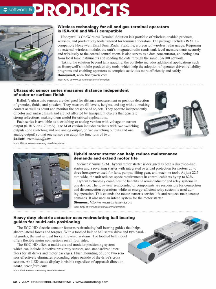
52 ● JULY 2013 CONTROL ENGINEERING ● www.controleng.com
Balluff’s ultrasonic sensors are designed for distance measurement or position detection of granules, fl uids, and powders. They measure fi ll levels, heights, and sag without making contact as well as count and monitor the presence of objects. They operate independently of color and surface fi nish and are not affected by transparent objects that generate strong refl ections, making them useful for critical applications.
Each series is available as a switching or analog version with voltage or current output (0-10 V or 4-20 mA). The M30 version includes variants with two switching outputs (one switching and one analog output, or two switching outputs and one analog output) so that one sensor can adopt the functions of two.Balluff, www.balluff.comInput #201 at www.controleng.com/information
Honeywell’s OneWireless Terminal Solution is a portfolio of wireless-enabled products, services, and productivity tools tailored for terminal operators. The package includes ISA100-compatible Honeywell Enraf SmartRadar FlexLine, a precision wireless radar gauge. Requiring no external wireless module, the unit’s integrated radio sends tank level measurements securely and wirelessly to the central control room. It also serves as a data concentrator, collecting data from local tank instruments and sending the data through the same ISA100 network.
Taking the solution beyond tank gauging, the portfolio includes additional applications such as Honeywell’s mobile productivity tools, which help the adoption of operator driven reliability programs and enabling operators to complete activities more effi ciently and safely.Honeywell, www.honeywell.comInput #200 at www.controleng.com/information
The EGC-HD electric actuator features recirculating ball bearing guides that helps absorb lateral forces and torques. With a toothed belt or ball screw drive and two paral-lel guides, the unit is ideal for cantilevered systems. The toothed belt model offers fl exible motor connections on all four sides.
The EGC-HD offers a multi axis and modular positioning system which can include inductive proximity sensors, and standardized inter-faces for all drives and motor packages. Flush mounting of up to two sen-sors effectively eliminates protruding edges outside of the drive’s cross section. An LED status display is visible regardless of approach direction.Festo, www.festo.comInput #203 at www.controleng.com/information
Siemens’ Sirius 3RM1 hybrid motor starter is designed as both a direct-on-line starter and a reversing starter with integrated overload protection for motors up to three horsepower used for fans, pumps, lifting gear, and machine tools. At just 22.5 mm wide, the unit reduces space requirements in control cabinets by up to 82%.
Hybrid technology combines the benefi ts of semiconductor and relay systems in one device: The low-wear semiconductor components are responsible for connection and disconnection operations while an energy-effi cient relay system is used dur-ing operation. This extends the motor starter’s service life and reduces maintenance demands. It also uses an infeed system for the motor starter.Siemens, http://www.usa.siemens.comInput #202 at www.controleng.com/information
Ultrasonic sensor series measures distance independentof color or surface finish
Wireless technology for oil and gas terminal operatorsis ISA-100 and Wi-Fi compatible
Heavy-duty electric actuator uses recirculating ball bearing guides for multi-axis positioning
Hybrid motor starter can help reduce maintenancedemands and extend motor life
PRODUCTSPRODUCTSsoftware &

Other opportunities to connectWhile our print magazines remain the touchpoint for more than 200,000 qualifi ed subscribers each month, we also recognize that there are so many other opportunities each day to reach busy end users. That’s why we’ve developed a wide range of ways to connect with our audience:
• Webcasts
• Videos
• Newsletters
• Websites
• RSS feeds
• An expanding global video library
• iPhone and Droid apps
• Social networks
Our goal?To give you the knowledge you need, when you need it, in the format you want it, delivered to the device you’re using, with the ability to utilize that knowledge to do your job better.
CFE Media1111 W. 22nd StreetOak Brook, IL 60523630-571-4070
www.cfemedia.com
Engineering is personal.So is the way you use information.
CFE Media delivers a world of knowledge to you. Personally.
Engineering is personal.So is the way you use information.
CFE Media delivers a world of knowledge to you. Personally.
You take pride in your profession — one of acquiring and applying design and build structures, machines, devices, systems, materials and processes that safely realize a solution to the needs of society.
And, to do your job better each day, you need a trusted source of information: CFE Media – Content For Engineers.
CFE Media strives to...• Inspire engineers to interact, respond to peers, and contribute to content that will assist other engineers with similar challenges.
• Develop an infrastructure that aligns, organizes and maps content to audiences specialized needs and business opportunities.
• Fully understand our audience and its changing needs for targeted information and delivery channels through the use of industry experts and leaders.
CFE Media is home to three of the most trusted names in the business: Consulting-Specifying Engineer — provides the latest knowledge on commercial and institutional facility construction and management. Visit www.csemag.com
Control Engineering — delivers a wide array of strategies and solutions to help control system designers create a more effi cient process. Visit www.controleng.com
Plant Engineering — delivers plant-fl oor knowledge and expertise to help manufacturers operate smarter, safer and more effi ciently. Visit www.plantengineering.com
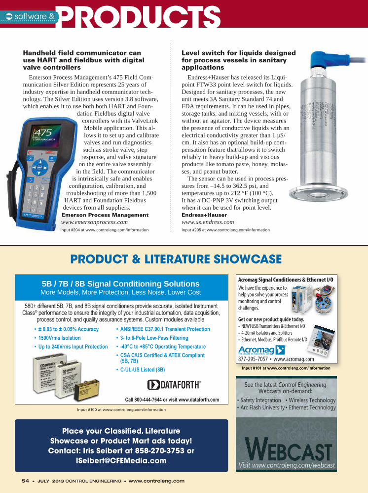
PRODUCT & LITERATURE SHOWCASE
Place your Classified, LiteratureShowcase or Product Mart ads today!
Contact: Iris Seibert at 858-270-3753 or [email protected]
• ± 0.03 to ± 0.05% Accuracy• 1500Vrms Isolation• Up to 240Vrms Input Protection
More Models, More Protection, Less Noise, Lower Cost
580+ different 5B, 7B, and 8B signal conditioners provide accurate, isolated Instrument Class® performance to ensure the integrity of your industrial automation, data acquisition,
process control, and quality assurance systems. Custom modules available.
Call 800-444-7644 or visit www.dataforth.com
5B / 7B / 8B Signal Conditioning Solutions
• ANSI/IEEE C37.90.1 Transient Protection• 3- to 6-Pole Low-Pass Filtering• -40°C to +85°C Operating Temperature• CSA C/US Certified & ATEX Compliant (5B, 7B)• C-UL-US Listed (8B)
Input #100 at www.controleng.com/information
Input #101 at www.controleng.com/information
See the latest Control Engineering Webcasts on-demand:
• Safety Integration• Arc Flash University
• Wireless Technology• Ethernet Technology
Visit www.controleng.com/webcast
Input #101 at www.controleng.com/information
877-295-7057 � www.acromag.com
Acromag Signal Conditioners & Ethernet I/OWe have the experience to help you solve your process monitoring and control challenges.
Get our new product guide today.• NEW! USB Transmitters & Ethernet I/O• 4-20mA Isolators and Splitters• Ethernet, Modbus, Profi bus Remote I/O
54 ● JULY 2013 CONTROL ENGINEERING ● www.controleng.com
Emerson Process Management’s 475 Field Com-munication Silver Edition represents 25 years of industry expertise in handheld communicator tech-nology. The Silver Edition uses version 3.8 software, which enables it to use both both HART and Foun-
dation Fieldbus digital valve controllers with its ValveLink Mobile application. This al-lows it to set up and calibrate valves and run diagnostics such as stroke valve, step response, and valve signature
on the entire valve assembly in the fi eld. The communicator
is intrinsically safe and enables confi guration, calibration, and
troubleshooting of more than 1,500 HART and Foundation Fieldbus devices from all suppliers.Emerson Process Managementwww.emersonprocess.comInput #204 at www.controleng.com/information
Endress+Hauser has released its Liqui-point FTW33 point level switch for liquids. Designed for sanitary processes, the new unit meets 3A Sanitary Standard 74 and FDA requirements. It can be used in pipes, storage tanks, and mixing vessels, with or without an agitator. The device measures the presence of conductive liquids with an electrical conductivity greater than 1 µS/cm. It also has an optional build-up com-pensation feature that allows it to switch reliably in heavy build-up and viscous products like tomato paste, honey, molas-ses, and peanut butter.
The sensor can be used in process pres-sures from –14.5 to 362.5 psi, and temperatures up to 212 °F (100 °C). It has a DC-PNP 3V switching output when it can be used for point level.Endress+Hauserwww.us.endress.comInput #205 at www.controleng.com/information
Handheld field communicator canuse HART and fieldbus with digitalvalve controllers
Level switch for liquids designed for process vessels in sanitary applications
PRODUCTSPRODUCTSsoftware &

www.controleng.com ● CONTROL ENGINEERING JULY 2013 ● 55
CFE Media Contributor Guidelines Overview
Content For Engineers. That’s what CFE Media stands for, and what CFE Media is all about – engineers sharing with their peers. We welcome content submissions for all interested parties in engineering. We will use those materials online, on our website, in print and in newsletters to keep engineers informed about the products, solutions and industry trends.
www.controleng.com/contribute explains how to submit press releases, products, images and graphics, bylined feature articles, case studies, white papers, and other media.
* Content should focus on helping engi-neers solve problems. Articles that are com-mercial in nature or that are critical of other products or organizations will be rejected. (Technology discussions and comparative tables may be accepted if non-promotional and if contributor corroborates information with sources cited.)
* If the content meets criteria noted in guidelines, expect to see it first on our Web-sites. Content for our e-newsletters comes from content already available on our Web-sites. All content for print also will be online. All content that appears in our print maga-zines will appear as space permits, and we will indicate in print if more content from that article is available online.
* Deadlines for feature articles intended for the print magazines are at least two months in advance of the publication date. Again, it is best to discuss all feature articles with the appropri-ate content manager prior to submission.Learn more at:www.controleng.com/contribute
Allied Electronics . . . . . . . . . . 13. . . . . . . . 9 . . . . . . www.alliedelec.com
ASCO Valve, Inc. . . . . . . . . . . . 1. . . . . . . . . 2 . . . . . . www.ascovalve.com/today
AutomationDirect . . . . . . . . . . C2 . . . . . . . 1 . . . . . . www.automationdirect.com
AVG . . . . . . . . . . . . . . . . . . . . . Bellyband . . . . . . . . www.EZAutomation.net
Baldor Electric Company . . . . 9. . . . . . . . . 6 . . . . . . www.baldor.com
Beckhoff Automation LLC. . . . 10. . . . . . . . 7 . . . . . . www.beckhoff.com
CFE Media LLC . . . . . . . . . . . . 53. . . . . . . . . . . . . . . www.cfemedia.com
Control EngineeringE-Newsletters . . . . . . . . . . . . . P14. . . . . . . . . . . . . . www.controleng.com/newsletters
ITSENCLOSURES . . . . . . . . . . 35. . . . . . . 13 . . . . . www.itsenclosures.com
Mitsubishi ElectricAutomation Inc . . . . . . . . . . . . 15. . . . . . . 10 . . . . . www.meau.com
Moxa Technologies . . . . . . . . . 3. . . . . . . . . 3 . . . . . . www.moxa.com
National Instruments . . . . . . . 7. . . . . . . . . 5 . . . . . . www.ni.com
OPTO 22. . . . . . . . . . . . . . . . . . 11 . . . . . . . . 8 . . . . . . www.groov.com
PI North America. . . . . . . . . . . 4. . . . . . . . . 4 . . . . . . www.us.profinet.com
Schweitzer Engineering Labs 32. . . . . . . 14 . . . . . www.selinc.com/ce7
SEW Eurodrive Inc . . . . . . . . . C4 . . . . . . 24 . . . . . www.seweurodrive.com
System Integratorof the Year Awards . . . . . . . . . 33. . . . . . . . . . . . . . . www.controleng.com/SIY
Unitronics . . . . . . . . . . . . . . . . 22. . . . . . . 12 . . . . . www.unitronics.com
Vecoplan LLC. . . . . . . . . . . . . . 20. . . . . . . 11 . . . . . www.viccontrols.com
Yaskawa America, Inc. . . . . . . C3 . . . . . . 23 . . . . . www.yaskawa.com
Inside Process
American IndustrialSystems (AIS) . . . . . . . . . . . . . P10. . . . . . 20 . . . . . www.aispro.com
Emerson ProcessManagement . . . . . . . . . . . . . . P6. . . . . . . 17 . . . . . www.DeltaVSIS.com
Load Controls Inc.. . . . . . . . . . P7. . . . . . . 18 . . . . . WWW.LOADCONTROLS.COM
Maple Systems Inc . . . . . . . . . P11 . . . . . . 21 . . . . . www.maplesystems.com
Precision Digital Corp. . . . . . . P3. . . . . . . 15 . . . . . www.predig.com/modbus
RGB Spectrum . . . . . . . . . . . . P5. . . . . . . 16 . . . . . www.rgb.com
United Electric Controls . . . . . P12. . . . . . 22 . . . . . www.ueonline.com
Winsted Corporation . . . . . . . P8. . . . . . . 19 . . . . . www.winsted.com
Request more information about products and advertisers in this issue by using thehttp://controleng.com/information link and reader service number located near each.If you’re reading the digital edition, the link will be live. When you contact a company directly, please let them know you read about them in Control Engineering.
Company Page# RSN Web
AD INDEXControl Engineering
www.controleng.com
Advertising Sales Offices
GA, MI, AL, FL
Patrick Lynch(630) 571-4070 [email protected]
AR, IL, IN, IA, KS, KY, LA, MN, MO, MS, NE, ND, OK, OH, SD, TX, WI,
Central Canada
Bailey Rice(630) 571-4070 [email protected]
AK, AZ, CA, CO, HI, ID, MT, NV, NM, OR, UT, WA, WY,Western Canada Iris Seibert(858) [email protected]
CT, DE, MD, ME, MA, NC, NH, NY, NJ, PA, RI, SC, VA, VT, WV, DC, Eastern Canada
Julie Timbol(978) [email protected]
56 ● JULY 2013 CONTROL ENGINEERING ● www.controleng.com
Peter Welander
‘ Even though you probably don’t control indirect costs
directly, any time you can increase production, the
indirect cost gets divided by more units of output, so the indirect
cost per ton goes down.’
The article last month on how process engineers and operators are getting more involved in the business ele-ments of running a plant suggested that
operators need to learn some basic concepts of accounting. Accountants like to match costs with the activities that create products and income. The income a plant generates is easy enough to understand because the output is sold at a specif-ic price per ton. To figure out if you’re profitable, you have to compare income against cost.
Costs are a bit more complicated, and there are two main components. The first part is the direct cost (aka variable cost), which includes tangible things directly connected to production of your output. If your plant typically produces 100,000 tons of product per month, that requires a corresponding amount of feedstock, gas to fire boilers, operators to watch the process, electric-ity to run pumps, scrubbers, etc. What are the costs incurred to create that amount of product, or, reversed, what costs would not be there if we had not run production at all? Direct costs should vary directly with the level of output. Let’s say for the sake of argument, at normal production levels, direct costs for your plant add up to $600/ton, so total direct cost for a month is $60 mil-lion. (These numbers are all made up, so don’t read too much into them.)
Direct costs are the most obvious, and some-times casual observers believe their plant is far more profitable than it is because they assume that is the only cost element. The other side of the accounting coin is indirect costs, and that’s where things get more complicated.
Every plant has many kinds of costs that aren’t directly related to production:
� Rent or property costs for the facility� Maintenance (equipment and people)� Infrastructure (keeping the lights and air
conditioning on)� Security services� Loading dock� Plant office building, equipment, and staff� Non-production utilities, and� Assorted ancillary things.
Since indirect costs do not change with pro-duction levels, they tend to be relatively stable and so are sometimes called fixed costs. (Capital equipment is usually handled differently, so buy-ing a new reactor comes from a capital account.)
Accountants like to add up indirect costs for the month. Then they divide the total by the number of units produced for the month. So, continuing our model, let’s say indirect costs are $2,000,000 per month. We divide that according to our output of 100,000 tons, so the indirect cost per ton is $20.
That means the total cost per ton is $620. Anything beyond that will be handled farther up the food chain. Others will deal with the gross margin, etc. Ultimately, you can make things bet-ter or worse by making your cost lower or higher. So, how can you improve things?
Raw materials—You might not have any influence on what you pay for feedstock, but you should be able to help improve efficiency and reduce the amount lost in production.
Energy—Again, maybe you can’t control pricing, but you can help control consumption.
Output—Even though you probably don’t control indirect costs directly, any time you can increase production, the indirect cost gets divid-ed by more units of output, so the indirect cost per ton goes down.
Your accountants establish standard costs for your products based on experience. When the actual cost deviates from the standard, it’s called a variance, which can be favorable or unfavor-able. Unfavorable is when production goes down because of an outage, and now you have fewer units of output and the indirect cost goes up per ton. Or, your energy efficiency goes down because a heat exchanger is fouling and it drives up your direct cost. That’s a bad thing.
Favorable is when you find opportunities to increase output, improve efficiency, or do some-thing else to come in under the standard cost. That draws the kind of attention you want. ce
Peter Welander is a content manager for Control Engineering, and got an A in his cost accounting class. [email protected]
BASICSBASICSBasic cost accountingfor process manufacturing
back to
As business aspects of running a process plant become more important tooperators, it helps to understand some simple accounting concepts.
� Subscribe to the Process & Advanced Control eNewslet-ter at www.controleng.com/newsletters.
Go Online

YA S K AWA A M E R I C A , I N C .D R I V E S & M O T I O N D I V I S I O N
1 - 8 0 0 -YA S K AWA YA S K AWA . C O M
Follow us: More Info:http://Ez.com/yai500
©2013 Yaskawa America Inc.
WHAT YOUALWAYS WANTED
Our customers tell us that quality means no product hardware failures. Now, that’s a gift that keeps on giving.
When you take Yaskawa drives out of the box, you can count on them to work. In fact, Yaskawa products have a meantime-between-failure rate (MTBF) of up to 28 years. That means your engineers can spec Yaskawa and never have to worry. Just program, plug and play.
Get what you want, every time. Call Yaskawa.
input #23 at www.controleng.com/information

Feeling Trapped?
Feeling trapped with your current fi eldbus supplier?
We understand the investment you have in your
PLC and control system. So, we designed our
gateways and fi eldbus cards to speak your language!
Free yourself from programming and substantially
reduce the load on your main PLC. It’s simple with
our advanced solution modules. Just enter your
parameters and go! And, as always, the quality
customer service is free…
seweurodrive.com / 864-439-7537input #24 at www.controleng.com/information