Embed Size (px)
Citation preview

dtiDEVELOPMENT, INSTALLATION AND TESTING OF A LARGE SCALE TIDAL CURRENT TURBINE
CONTRACT NUMBER: T/06/0021/00/REP
URN NUMBER: 05/1698

The DTI drives our ambition of ‘prosperity for all’ by working to create the best environment for business success in the UK.We help people and companies become more productive by promoting enterprise, innovation and creativity.
We champion UK business at home and abroad. We invest heavily in world-class science and technology.We protect the rights of working people and consumers. And we stand up for fair and open markets in the UK, Europe and the world.

DEVELOPMENT, INSTALLATION AND TESTING OF A LARGE-SCALE TIDAL
CURRENT TURBINE
T/06/00210/00/REP URN 05/1698
ContractorsIT Power
Marine Current Turbines, Seacore, Bendalls Engineering, Corus
Prepared byJeremy Thake, IT Power
The work described in this report was carried out under contract as part of the DTI Technology Programme: New and Renewable Energy, which is managed by Future Energy Solutions. The views and judgements expressed in this report are those of the contractor and do not necessarily reflect those of the DTI or Future Energy Solutions.
First published October 2005 © Crown Copyright

CONTENTS
CONTENTS........................................................................................................................... 1EXECUTIVE SUMMARY...................................................................................................... 31. BACKGROUND.......................................................................................................... 4
1.1 Previous Work......................................................................................................... 41.2 Resource & Cost Estimates..................................................................................... 51.3 Partnership & Complementary Projects...................................................................6
2. COMPETITIVE TIDAL STREAM TECHNOLOGIES.................................................. 72.1 Designs.....................................................................................................................72.2 Competitors..............................................................................................................72.3 Commercial Status .................................................................................................. 7
3. PROJECT OBJECTIVES.......................................................................................... 124. SITE SELECTION......................................................................................................12
4.1 Site Selection Criteria ............................................................................................ 134.1.1 General Site Selection Principles.................................................................... 134.1.2 Seaflow Site.....................................................................................................14
4.2 Site Permissions.....................................................................................................144.3 Environmental Impact............................................................................................ 16
4.3.1 Possible Impacts............................................................................................. 164.3.2 Objections & Concerns Raised ....................................................................... 174.3.3 EIA Survey Results ......................................................................................... 174.3.4 Future EIA Recommendations........................................................................ 18
5. DESCRIPTION OF THE TURBINE........................................................................... 195.1 Concept Design......................................................................................................195.2 Rotor.......................................................................................................................205.3 Powertrain & Electrical System.............................................................................. 215.4 Control System, Instrumentation & Communications............................................ 215.5 Structure & Foundation.......................................................................................... 235.6 Access ....................................................................................................................265.7 Servicing.................................................................................................................265.8 Intellectual Property Rights (IPR), Patents............................................................26
6. MANUFACTURE & PRE-INSTALLATION TESTING.............................................. 277. INSTALLATION........................................................................................................ 288. COMMISSIONING, TESTING & MAINTENANCE.....................................................319. TEST RESULTS....................................................................................................... 33
9.1 Rotor Power Output............................................................................................... 339.2 Flow Characteristics .............................................................................................. 369.3 Rotor Performance & Energy Capture...................................................................38
10. EVALUATION OF OPERATIONS.............................................................................3910.1 Turbine Design................................................................................................... 39
10.1.1 Site Conditions............................................................................................. 3910.1.2 Visual Impact............................................................................................... 3910.1.3 Pitch Control ................................................................................................ 3910.1.4 Marine Growth ............................................................................................. 3910.1.5 Cables & Connectors...................................................................................40
10.2 Installation .......................................................................................................... 4010.2.1 Site Investigation.......................................................................................... 4010.2.2 Installation Equipment.................................................................................. 40
1

10.3 Operation & Maintenance................................................................................... 4110.3.1 Access ......................................................................................................... 4110.3.2 Maintenance ................................................................................................ 41
10.4 Evaluation Against Objectives............................................................................4111. COSTS.......................................................................................................................42
11.1 Seaflow Costs .................................................................................................... 4211.1.1 Turbine Quayside Costs...............................................................................4311.1.2 Installation Costs.......................................................................................... 4311.1.3 Energy Produced......................................................................................... 4311.1.4 Operation & Maintenance Costs..................................................................4411.1.5 Overhead Costs........................................................................................... 4511.1.6 Cost of Capital............................................................................................. 45
11.2 Predicted Future Costs....................................................................................... 4512. FUTURE WORK....................................................................................................... 49
12.1 Further Development Work on Seaflow..............................................................4912.2 Technology Development................................................................................... 4912.3 Installation Development.................................................................................... 50
13. CONCLUSIONS........................................................................................................ 51APPENDICES.....................................................................................................................52
APPENDIX 1.........................................................................................................................53LIST OF ABBREVIATIONS, GLOSSARY OF TERMS, ETC.......................................... 53
APPENDIX II........................................................................................................................54PARTNERSHIPS..............................................................................................................54
APPENDIX III.......................................................................................................................58CONSULTATIONS.......................................................................................................... 58
APPENDIX IV......................................................................................................................59SUMMARY ENVIRONMENTAL STATEMENT................................................................59
2
EXECUTIVE SUMMARY
Seaflow has been a project to develop and test a commercially-sized marine current turbine. The turbine was installed in the summer of 2003 off Foreland Point, near Lynmouth on the North Devon coast of England. The objectives of the project were to test the feasibility of constructing and operating such a machine, to ascertain whether the performance would be as predicted, and to evaluate the likely longer-term economics of using such tidal turbines to generate electricity.The Seaflow turbine is a 300kW, horizontal-axis machine that resembles a 2-bladed wind turbine, but with the rotor underwater. The turbine is mounted on a steel pile fixed into a socket in the seabed, and the powertrain - the rotor, gearbox and generator - can be slid up and down the pile and out of the water for servicing.The project was co-ordinated by the renewable energy consultancy, IT Power. The other partners were: Seacore, a marine construction company; Marine Current Turbines Ltd, a company set up by the partners to carry forward the development of the technology; Bendalls Engineering, a large engineering fabricator; and Corus, the steel manufacturer.A parallel project funded by the European Commission also had IT Power as the coordinator and Seacore as a partner, but included as partners ISET, a research organisation attached to Kassel University, and Jahnel-Kesterman, a specialist gearbox manufacturer.The first stage of the project was to identify a site for the turbine and obtain all the necessary permissions to install it, part of which involved conducting an Environmental Impact Assessment into the turbine’s effects on marine life and processes, the landscape, and other sea users.The consortium then developed the machine from concept to detailed designs, manufactured or purchased the components, and assembled and tested the prototype.The installation was carried out by a jack-up barge that could stand on legs on the seabed, providing a stable platform for drilling and assembly. No diver operations were required.Testing has confirmed the design philosophy, and the turbine has performed as predicted. At the end 2004 the turbine had been operated on 68 separate days, recording 80 hours of operation. The turbine has served as a testbed, being operated for numerous short runs to test the principles of generation or to develop components. Continuous operation for more extended periods has been limited, as the reliability of the various systems has been developed.Though the project officially ended in 2004, the turbine has not been decommissioned. Over two years after the installation, the machine is still working, and an extended test programme continues with DTI support.New techniques have been developed to install the turbine in a deep, high current area, and much has been learnt about working in such an environment. The project has increased understanding of the nature of tidal flows, and the behaviour of a rotor in tidal currents.Seaflow lays the foundations for the development of a new industry, exploiting what is a sizeable renewable energy resource. The partners plan to follow Seaflow with further, larger machines, and to move to commercial farms thereafter.
3
1. BACKGROUND
1.1 Previous Work
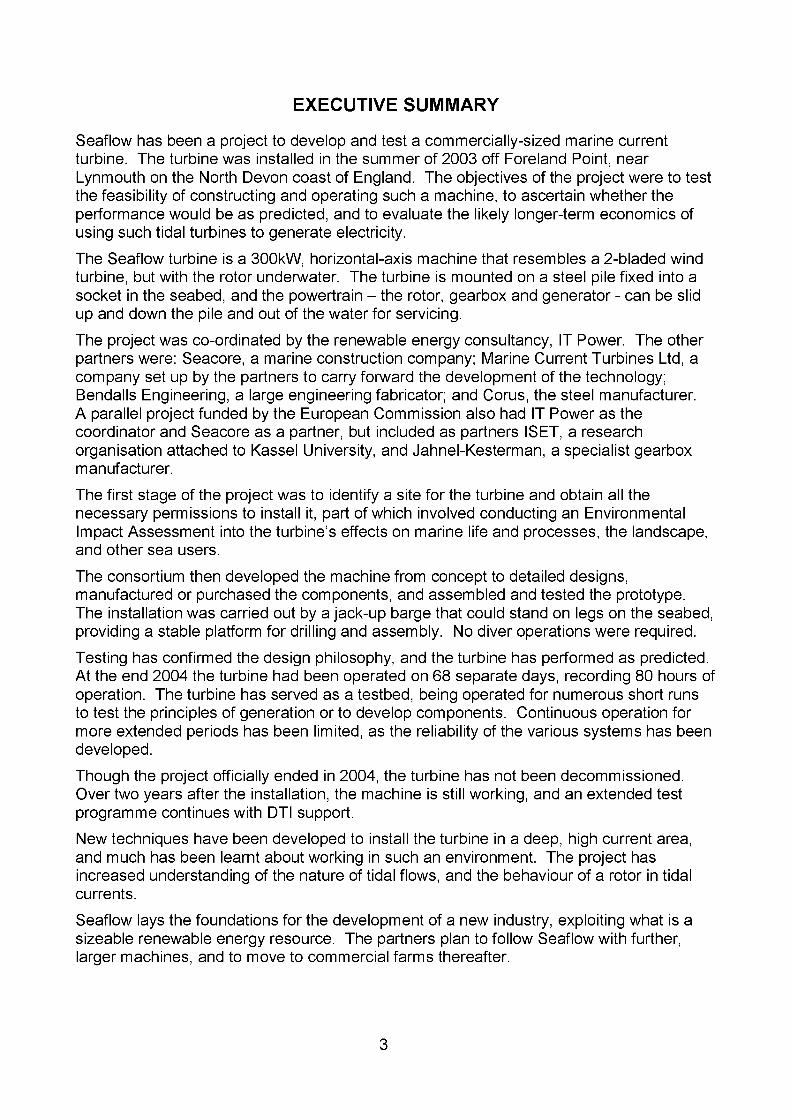
The origins of the Seaflow project can be traced back a long way, starting with a river current turbine project that ran from 1976-84. One of the instigators was Peter Fraenkel, initially from within ITDG but then in the newly-formed IT Power. The turbine used a vertical-axis Darrieus-type rotor, and was moored off the bank of the river Nile in Juba, Sudan, where it was used for irrigation pumping. The turbine performed well, pumping 2000 litres/hour through a head of 5m from a current of 1 m/s. The design was subsequently developed further, and has been marketed with a horizontal-axis rotor as both a water pump and an electric generator.
Figure 1: River current turbine on the Nile, Sudan, 1982
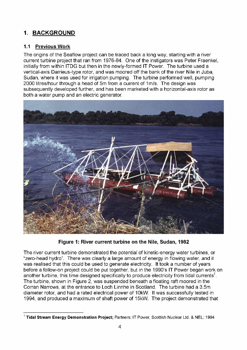
The river current turbine demonstrated the potential of kinetic-energy water turbines, or “zero-head hydro”. There was clearly a large amount of energy in flowing water, and it was realised that this could be used to generate electricity. It took a number of years before a follow-on project could be put together, but in the 1990’s IT Power began work on another turbine, this time designed specifically to produce electricity from tidal currents1. The turbine, shown in Figure 2, was suspended beneath a floating raft moored in the Corran Narrows, at the entrance to Loch Linnhe in Scotland. The turbine had a 3.5m diameter rotor, and had a rated electrical power of 10kW. It was successfully tested in 1994, and produced a maximum of shaft power of 15kW. The project demonstrated that
1 Tidal Stream Energy Demonstration Project; Partners: IT Power, Scottish Nuclear Ltd. & NEL; 1994
4
such a rotor could generate power with a reasonable efficiency, but also showed significant difficulties working with moorings.In the following years, IT Power was involved with several feasibility studies for tidal turbines2. During this time the concept of a pile-mounted turbine was developed in conjunction with Seacore, a company which already used large-diameter monopiles for general marine construction work.The Seaflow project started with a grant from the European Commission in 1998. The partners also approached the DTI for support, and this led to an independent study being commissioned on the feasibility of the concept3, which was generally supportive of the technology. The DTI began grant support to the Seaflow project in June 2001.
Figure 2: The Loch Linnhe turbine being deployed.
1.2 Resource & Cost Estimates
In parallel with technology development, IT Power was studying the potential tidal resource. Two main projects were completed, one for the EC4, and one for the UK
2 Feasibility Study of Tidal Current Power Generation for Coastal Waters: Orkney & Shetland; Project for Orkney Islands Council and Shetland Islands Council under EU Contract XVII/4 1040/92-41; Partners: International Centre for Island Technology, IT Power; 19953 Commercial Prospects For Tidal Stream Power; DTI New & Renewable Energy Programme; Partners: Binnie, Black & Veatch and IT Power; 2000-1.4 CENEX, Tidal & Marine Current Energy Exploitation; JOU2-CT94-0355; Partners: Tecnomare SpA, IT Power, Ponte di Archimede nello Stretto di Messina SpA, Tecnomare UK Ltd, University of Patras; 1994-6.
5

government5. Both of these studies included some outline techo-economic feasibility, and this was further extended in another EC project, OptCurrent6. The conclusions were that there was a very significant potential for tidal stream development, and that it was likely that electricity could be generated at economic rates.
1.3 Partnership & Complementary Projects
Seaflow has been a co-operative effort of multiple partners and multiple funding agencies. The work originally started with the EC project on 1 September 1998. The UK Department of Trade and Industry (DTI) project to support Seaflow was initiated on 1 June 2001: Development, Installation and Testing of a Large-Scale Tidal Current Turbine. The work also benefited from a German government project, Control and management of variable speed marine current turbines on variable-speed powertrains for tidal turbines.This led to a consortium of seven organisations working on Seaflow, with a wide and complementary range of experience and skills. Both the EC and DTI projects were coordinated by IT Power, but only IT Power and Seacore were in both projects. The structure is summarised in Figure 3, and the partners are listed in the APPENDIX II.
EUROPEAN PROJECT Supported by EC
UK PKUJEGI supporter! hv I > 11
Jahnel-KestermannGearbox design & manufacture
IT PowerProject Co-ordinator
Design, procurement & testing
MCTDesign, testing & commercial development of technology
SeacoreDesign, installation, offshore operations
Bendalls EngineeringDesign detailing,
steel fabrication & assembly
CornsSteel supply,
technical assistance
Figure 3: The relationship of the various projects and partners behind Seaflow.
The rather complex interlinking of the projects reflected the complexity of the work, and the need to raise a considerable amount of finance. The overall budget was around £3.2 million, of which £1 3m was grant from the DTI and £600k was from the EC. Some assistance was received in hardware from the BMWi project, to a value of around £60k. The remainder was financed by the partners.
5 UK Tidal Stream Energy Review; ETSU, Dept, of Energy, DTI, UK; Partners: Engineering & Power Development Consultants, Binnie & Partners, Sir Robert McAlpine & Sons Ltd. & IT Power; 1992-36 OptCurrent, Optimising the Performance (Electrical and Economic) of Tidal Current Turbines, EC Contract No. JOR3CT980205; Partners: Robert Gordon University, IT Power, University College Cork, Thetis; 1998- 2001.
6

It was agreed that Marine Current Turbines Ltd., one of the partners in the DTI project, would be the ultimate owners of the Intellectual Property Rights arising from the project, as it would be developing the subsequent commercial technology.
2. COMPETITIVE TIDAL STREAM TECHNOLOGIES
2.1 DesignsAs in the early stages of other technologies, such as wind and wave, many different tidal stream concepts have been, and continue to be, proposed. Most are based on rotating rotors, either horizontal or vertical-axis. Some horizontal-axis machines have flow enhancers, in the form or diffusers or concentrators, that take the flow from a larger area and funnel it into a smaller rotor. The main types are summarised below:
• Horizontal axis turbines:e.g. Seaflow, Hammerfest Strom, TidEl, THGL.
• Horizontal-axis turbines with concentrators or diffusers: e.g. Lunar Energy, Teamwork Technology, UEK.
• Vertical axis turbines:Davis, Kobold, Gorlov, Edinburgh University, Waverotor.
There are a few turbines that work on fundamentally different principles, notably the Stingray turbine which has a single “wing” that flaps up and down in the current, and the Rochester Venturi which runs a conventional turbine on the pressure drop generated by a constriction in the flow.
2.2 Competitors
A brief description of various competitive turbines is given below. It is not appropriate here to enter into a discussion of the merits of the various concepts, particularly since a number of the projects have also received grant funding from the dTi.This list shows the major projects. In addition to these there are numerous academic groups, individuals and small companies that have proposed different forms of tidal turbines. Many of these are simply ideas, but some have been tested at a small scale.
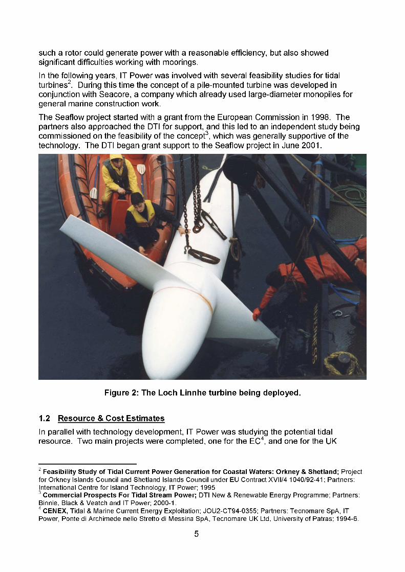
2.3 Commercial Status
As yet, no tidal turbines are commercially available. A number of devices have been, or are being, tested on a small scale, and a handful of machines have been tried as full-scale prototypes. Having had a large-scale prototype installed for over one year, the Seaflow concept is one of the forerunners in the race to a commercial machine, and MCT is already working on a pre-commercial prototype, which will then be extended to a small farm.
7
Device Name Company/Organisation and device name(s)
Description Website
Seaflow/Seagen Marine Current Turbines Ltd Axial flow rotors with full-span pitch control mounted on monopile support structure - Seaflow 300kW single rotor experimental test system installed May 2003 and Seagen is 1MW twin rotor commercial prototype under development for installation in 2006.
www.marineturbines.com
Blue Concept Hammerfest Strom Horizontal-axis turbine, 3-blade rotor, rated at 300kW. Fully submerged on gravity foundation. Installed in Norwegian fjord in December 2002. Has support from Statoil and formerly from ABB (Norway) and Rolls Royce. No new information released from web site since 2002.
www.e-tidevannseneroi.com
Rotech Tidal Turbine
Rotech/Lunar Energy Horizontal-axis turbine in a double ended duct- diffuser. Model tests completed at Glasgow University. Technology developed by Rotech of Aberdeen which produces suction dredging pumps. A 1MW system to be tested in 2005(7), with larger turbines to follow. The project has been part-funded by a DTI New and Renewable Energy R&D grant.
www. lunarenerov. co.uk
Stingray The Engineering Business Full-scale prototype tested for two short periods in Shetland. Rated at 150kW. The project has been part-funded by a DTI New and Renewable Energy R&D grant. Future development “on hold”.
www.enob.com
8
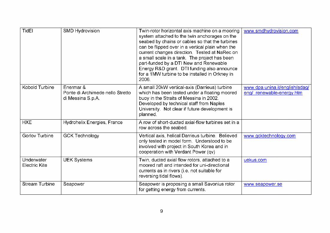
TidEI SMD Hydrovision Twin-rotor horizontal axis machine on a mooring system attached to the twin anchorages on the seabed by chains or cables so that the turbines can be flipped over in a vertical plain when the current changes direction. Tested at NaRec on a small scale in a tank. The project has been part-funded by a DTI New and RenewableEnergy R&D grant. DTI funding also announce for a 1 MW turbine to be installed in Orkney in 2006.
www.smdhvdrovision.com
Kobold Turbine Enermar &Ponte di Archimede nello Stretto di Messina S.p.A.
A small 20kW vertical-axis (Darrieus) turbine which has been tested under a floating moored buoy in the Straits of Messina in 2002.Developed by technical staff from Naples University. Not clear if future development is planned.
www.doa.unina.it/enqlish/adaq/enq/ renewable-enerqv.htm
HXE Hydrohelix Energies, France A row of short-ducted axial-flow turbines set in a row across the seabed.
Gorlov Turbine GCK Technology Vertical axis, helical Darrieus turbine. Believed only tested in model form. Understood to be involved with project in South Korea and in cooperation with Verdant Power (qv)
www.qcktechnoloqv.com
Underwater Electric Kite
UEK Systems Twin, ducted axial flow rotors, attached to a moored raft and intended for uni-directional currents as in rivers (i.e. not suitable for reversing tidal flows).
uekus.com
Stream Turbine Seapower Seapower is proposing a small Savonius rotor for getting energy from currents.
www. seapower. se
9
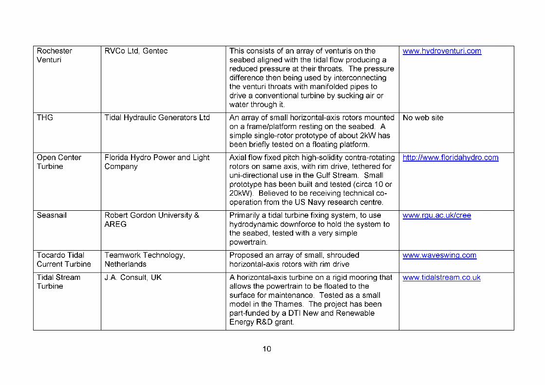
RochesterVenturi
RVCo Ltd, Gentec This consists of an array of venturis on the seabed aligned with the tidal flow producing a reduced pressure at their throats. The pressure difference then being used by interconnecting the venturi throats with manifolded pipes to drive a conventional turbine by sucking air or water through it.
www.hvdroventuri.com
THG Tidal Hydraulic Generators Ltd An array of small horizontal-axis rotors mounted on a frame/platform resting on the seabed. A simple single-rotor prototype of about 2kW has been briefly tested on a floating platform.
No web site
Open Center Turbine
Florida Hydro Power and Light Company
Axial flow fixed pitch high-solidity contra-rotating rotors on same axis, with rim drive, tethered for uni-directional use in the Gulf Stream. Small prototype has been built and tested (circa 10 or 20kW). Believed to be receiving technical cooperation from the US Navy research centre.
http://www.floridahvdro.com
Seasnail Robert Gordon University &AREG
Primarily a tidal turbine fixing system, to use hydrodynamic downforce to hold the system to the seabed, tested with a very simple powertrain.
www.rou.ac.uk/cree
Tocardo Tidal Current Turbine
Teamwork Technology,Netherlands
Proposed an array of small, shrouded horizontal-axis rotors with rim drive
www waveswinq.com
Tidal Stream Turbine
J.A. Consult, UK A horizontal-axis turbine on a rigid mooring that allows the powertrain to be floated to the surface for maintenance. Tested as a small model in the Thames. The project has been part-funded by a DTI New and RenewableEnergy R&D grant.
www.tidalstream.co.uk
10
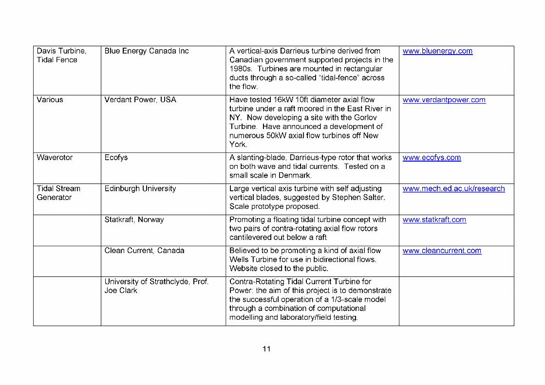
Davis Turbine, Tidal Fence
Blue Energy Canada Inc A vertical-axis Darrieus turbine derived from Canadian government supported projects in the 1980s. Turbines are mounted in rectangular ducts through a so-called “tidal-fence” across the flow.
www.bluenerov.com
Various Verdant Power, USA Have tested 16kW 10ft diameter axial flow turbine under a raft moored in the East River in NY. Now developing a site with the Gorlov Turbine. Have announced a development of numerous 50kW axial flow turbines off NewYork.
www.verdantoower.com
Waverotor Ecofys A slanting-blade, Darrieus-type rotor that works on both wave and tidal currents. Tested on a small scale in Denmark.
www.ecofvs.com
Tidal Stream Generator
Edinburgh University Large vertical axis turbine with self adjusting vertical blades, suggested by Stephen Salter. Scale prototype proposed.
www.mech.ed.ac.uk/research
Statkraft, Norway Promoting a floating tidal turbine concept with two pairs of contra-rotating axial flow rotors cantilevered out below a raft
www.statkraft.com
Clean Current, Canada Believed to be promoting a kind of axial flow Wells Turbine for use in bidirectional flows. Website closed to the public.
www. cleancurrent. com
University of Strathclyde, Prof.Joe Clark
Contra-Rotating Tidal Current Turbine forPower: the aim of this project is to demonstrate the successful operation of a 1/3-scale model through a combination of computational modelling and laboratory/field testing.
11

3. PROJECT OBJECTIVESThe main objectives of both the DTI and the EC projects were similar: to design, manufacture, install, and test a commercially-sized marine current turbine. Specific objectives for the DTI project were:
1. To design and develop an experimental tidal current turbine rated at approximately 300 kW
2. To manufacture, install, commission and operate the turbine for at least one year so as to gain a detailed insight into the engineering requirements and costs involved.
3. To evaluate the impact of the installed marine current turbine on the environment.4. To conduct full-scale testing of a marine current turbine to determine the
parameters that affect its performance, and hence to get a clearer view of the optimum configurations for future machines.
5. To evaluate techniques for installing, operating, servicing and maintaining as well as for decommissioning a marine current turbine.
6. To obtain more accurate cost predictions for the capital equipment, installation, operation and decommissioning of commercial marine current turbines.
The project also had a number of more specific development targets:
• Maximum rotor power coefficient CP of 0.4.
• Electrical power output of 300 kW in a current of 2.7 m/s.
• Installed cost of £900,000, or £3,000/kW, for turbine and installation costs.
• Installation, operation, maintenance, and decommissioning achieved without diver intervention.
• Performance reduction due to marine growth limited to 5% between 1-year maintenance periods.
• Development of an accurate mathematical model for the turbine that predicts the output to within 2% in steady-state conditions.
• One month’s continuous operation without intervention or stoppage.
• Operating point to be achieved without major cavitation.
4. SITE SELECTIONThe search for a site began with a study of available tidal information, such as UK Admiralty Tidal Atlases & Charts, and ships’ pilots. Various other studies were consulted, such as the CENEX study from EC CEnEx project7 and the UK Tidal Stream Energy Review8. Advice was sought from marine consultants, marine construction companies, harbour authorities, universities with marine or oceanographic departments, and marine sports groups.
7 Marine Currents Energy Extraction: Resource Assessment; Tecnomare, ENEL, IT Power, Ponte di Archimede, University of Patras; Final Report of EU-Joule Contract JOU2-CT93-0355; 1995.8 UK Tidal Stream Energy Review; Engineering & Power Development Consultants, Binnie & Partners, Sir Robert McAlpine & Sons Ltd. & IT Power; Report for ETSU, Dept. of Energy, DTI, UK; ETSU Report No. T/05/00155/REP; 1993.
12

4.1 Site Selection Criteria
The key criteria for selecting sites were:
• 2-3m/s maximum spring peak current (4-6 knots), in order to achieve an economic size of rotor;
• Uniform flow with strong currents for long periods to maximise power available;
• Minimum depth 15m to chart datum or lowest astronomical tide (LAT), to provide adequate space for a rotor;
• Maximum depth 25m, to remain within capability of Seacore’s largest available jack-up barge at the time;
• Close to the coast (preferably < 1km);
• Reasonably close to Seacore’s base (to keep mobilisation overhead costs down), and to be accessible from IT Power;
• Not too exposed to open sea waves and wind, to reduce the risk of weather- induced delays and to maximise time available for installation and servicing;
• No major conflicts with other sea users;
• Avoiding sensitive environmental sites.
This preliminary study led to a shortlist of possible sites around the coast of England and Wales. Many other good tidal sites were identified off Scotland, Ireland, and the Channel Islands, but were not pursued as they were too distant from where the partners were based.
4.1.1 General Site Selection PrinciplesSome general principles for tidal current turbine site selection were noted. The MeanSpring Tide current over most of the continental shelf is quite low, less than 1 knot(0.5m/s). Higher currents are only found around certain features, such as:
• Channels or constrictions between islands - these provide some of the best sites, as the flow is fast and rectilinear;
• Headlands in the path of moderate flows - these are best when the headlands are large and do not protrude too sharply into the flow, otherwise the flows are fast but turbulent, and the high currents may be in different places on ebb and flood;
• Estuaries or other resonant water volumes - good sites with rectilinear flow, but combined with high tidal ranges;
• Narrow entrances to enclosed tidal lakes - these can have very high currents, but only over a small area.
Using these observations, large-scale maps can be used to predict possible sites, but inmany places there is insufficient published data to verify whether an actual site is suitable.As marine current exploitation develops, there will be a need for a detailed inventory ofpotential sites.
13
On small-scale maps, areas that do have high currents appear very small, though in reality each one may be several kilometres long in the direction of flow, and have space for many turbines, potentially generating tens or even hundreds of megawatts. Many suitable areas are several kilometres from the shore, and would be suitable for development as tidal “farms”, though they would be prohibitively expensive for a single, isolated turbine. In this respect, the search for a site for Seaflow was unusual, and it will be easier to find sites for larger developments where overhead costs can be more easily absorbed.
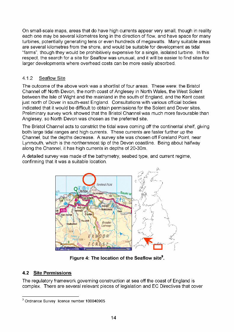
4.1.2 Seaflow SiteThe outcome of the above work was a shortlist of four areas. These were: the Bristol Channel off North Devon, the north coast of Anglesey in North Wales, the West Solent between the Isle of Wight and the mainland in the south of England, and the Kent coast just north of Dover in south-east England. Consultations with various official bodies indicated that it would be difficult to obtain permissions for the Solent and Dover sites. Preliminary survey work showed that the Bristol Channel was much more favourable than Anglesey, so North Devon was chosen as the preferred site.The Bristol Channel acts to constrict the tidal wave coming off the continental shelf, giving both large tidal ranges and high currents. These currents are faster further up the Channel, but the depths decrease. A survey site was chosen off Foreland Point, near Lynmouth, which is the northernmost tip of the Devon coastline. Being about halfway along the Channel, it has high currents in depths of 20-30m.A detailed survey was made of the bathymetry, seabed type, and current regime, confirming that it was a suitable location.
Figure 4: The location of the Seaflow site9.
4.2 Site Permissions
The regulatory framework governing construction at sea off the coast of England is complex. There are several relevant pieces of legislation and EC Directives that cover 9
9 Ordnance Survey licence number 100040905
14

coastal waters, and these are administered by different government departments. When applications were made for licences for Seaflow, even the departments themselves were unclear as to which legal Acts applied, and how areas of apparent overlap were to be resolved. The situation has improved somewhat during the project, partly due to the Seaflow project itself, but primarily because of the advent of offshore wind farms. The various government departments have now created a single point of contact for marine licensing, but this was not the case when the Seaflow applications were made.The consents to be obtained for a marine current turbine fall into four broad categories:
• Lease arrangements for the seabed;
• Navigation and shipping interests;
• Marine environment and usage;
• Cable and electrical connections on land.
Lease arrangements for the seabed are relatively straightforward, and are handled by The Crown Estate, which owns nearly all the seabed around the UK within the 12 nautical mile limit.Navigation and shipping in UK coastal waters are the responsibility of the Department for Transport. (The government department responsible for transport was initially DETR, then became DlTr, and then DfT during the project.) There were two possible legislative routes to obtaining permission: one was the Coastal Protection Act 1949, Section 34 (CPA), and the other was the Transport and Works Act 1992 (TWA). In consultation with officials it was felt that the CPA was more appropriate for a single experimental turbine than the wide-ranging procedures of the tWA. Obtaining permission under the Coastal Protection Act requires advertising the proposal and consultation, the scope of which is limited to issues of obstruction of navigation routes and safety. The project was also advised that the installation came within the scope of the Harbour Works (Environmental Impact Assessment) Regulations 1999, which meant that the department responsible for transport required an Environmental Impact Assessment.The legislation covering the marine environment and usage is the responsibility of the Department for Environment, Food and Rural Affairs, DEFRA (which was called MAFF at the beginning of the project). Permission needs to be obtained under the Food and Environmental Protection Act, 1985 (FEPA). EC Directives on Environmental Impact Assessments (Directives 85/337/EEC and 97/11/EC) are also implemented through FEPA. The FEPA process involves widespread consultation with environmental groups, fishermen and other sea-users, so the process can be lengthy and involved if objections are raised.The land-based consents for bringing a cable ashore and erecting switchgear are the responsibility of the local planning authority and the landowners. The project applied for planning permission for laying a cable across the beach at Lynmouth to a substation just on the seafront, and this was granted by the Exmoor National Park Authority on 7 March 2000. In the event, the turbine was not connected to the grid, and this permission was not used.Consultation was carried out with all the official bodies that have a statutory input to the consents process, in advance of submitting formal applications. Discussions were also held with many other local organisations which potentially had an interest in the project.
15
There was general enthusiasm for the tidal turbine concept, and the responses were nearly all positive.Official applications for permission to install were made in 2001. A FEPA licence was granted by DEFRA on 20 March 2002. This had to be renewed in 2003 as the installation began just outside the twelve month licence period. Permission was granted by DfT under the Coastal Protection Act on 5 April 2002. A rental agreement was made with The Crown Estate dated 8 May 2003, after the other permissions were received, as this was conditional upon the granting of all other licences.The Crown Estate required that the turbine should have third party insurance covering third-party liability to other sea users, and that the consortium should provide guarantees that the turbine would be removed at the end of the project. This guarantee was made by Seacore, which was considered to have sufficient financial stability to make the commitment. The insurance proved more of a difficulty, as the world-wide insurance market became unstable after the 11 September attacks in USA in 2001. Eventually, a special agreement with Seacore’s normal insurance brokers allowed the consortium to obtain insurance, though at a rate above previous estimates.
4.3 Environmental Impact
One of the pre-requisites for the FEPA licence was that the project produce an Environmental Statement, ES. Since an ES was also required for the Harbours Act, MAFF and DETR joined together to produce a scoping document for an Environmental Impact Assessment, El A. An independent consultant was contracted to undertake the study.The EIA and licence applications for Seaflow were groundbreaking, requiring the various authorities to think though the implications of marine current energy exploitation.
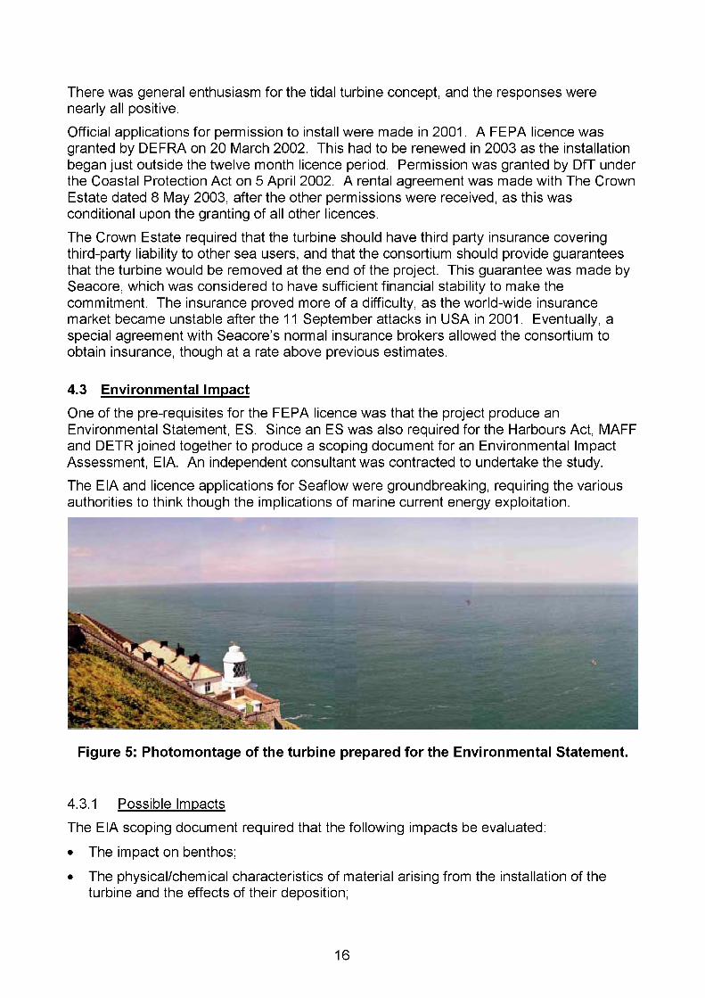
Figure 5: Photomontage of the turbine prepared for the Environmental Statement.
4.3.1 Possible ImpactsThe EIA scoping document required that the following impacts be evaluated:
• The impact on benthos;
• The physical/chemical characteristics of material arising from the installation of the turbine and the effects of their deposition;
16
• Effects on water flows;
• Impacts of construction on fish resources and invertebrates;
• Impacts on marine flora and fauna in terms of scouring of the sea bed and physical contact with fish, sea birds and mammals;
• The visual impact of the turbine structure above the water;
• The noise disturbance implications of the development;
• Possible effects on tourism;
• Highway access implications.
4.3.2 Objections & Concerns RaisedConcerns raised during the consultations were relatively few, and all were addressed within the Environmental Statement.There was some concern that lobster potting conducted out of Lynmouth could be disturbed both by the turbine and the construction work. However, the turbine is well offshore of any lobster pot locations, and both the North Devon Sea Fisheries Committee and the local MaFF fisheries officer agreed that any disruption was unlikely to be serious. There were only two fishing boats operating out of Lynmouth, both engaged in lobster potting, and one of the fishermen moved out of the area before the turbine was installed.A number of ecological concerns were raised by English Nature and the Devon Wildlife Trust. English Nature was concerned that certain rare corals had been found in nearby areas, and could be present near the Seaflow site. It recommended that the turbine should avoid rocky habitat. The Devon Wildlife Trust requested that certain issues be addressed in the EiA: the disturbance to the seabed during construction, the risk of harm to sea mammals and fish from collision with the rotor, and the risk of leakage of pollutants. The Exmoor National Park Authority were concerned at the possible effects of scour on benthos, and the Lynton and Lynmouth Town Council (LLTC) wanted assurance that the turbine would not affect the sandbanks in the bay.More general concerns were expressed by LLTC and in a public meeting held in Lynmouth about the visual impact, and the audibility of the turbine foghorn.
4.3.3 EIA Survey ResultsA field survey into the possible impacts of the Seaflow turbine on the environment was carried out in July 2001. This resulted in the publication of an Environmental Statement in November 2001, looking into all the areas of concern raised in the government scoping document. It had a major section on the visual impact and landscape, a photomontage from which is shown in Figure 5.In general the conclusion of the ES was that the environmental impacts of the scheme were "minor” or "insignificant”, with the exception of the visual impact from the coast very close to the turbine.
17

Scale Duration Residuals Significance
Loca
l
Reg
iona
l
Nat
iona
l
Inte
rnat
iona
l
Sho
rt te
rm
Med
ium
term
Long
term
No r
esid
uals
Res
idua
ls
Maj
or
Mod
erat
e
Min
or
Physical environmentWave climate Z Z Z ZFlow Z Z Z ZSea bed / sediments z Z Z ZWater quality z Z Z ZBiological environmentHabitats/benthos Z Z Z ZMarine species z Z z zBirds z Z z zLandscape>3km z z z z2-3km z z z z1.5-2 km z z z Z1-1.5km z z z ZFisheries z z z zNavigation z z z zNoise z z z z
Table 1: Summary of impacts from the Seal low Environmental Statement
Other effects of the turbine are, as expected from the ES, relatively small, and therefore rather difficult to evaluate. There has been no rotor damage, which indicates that there have been no collisions with fish or sea mammals (or any other debris). Dolphins and diving birds are regularly seen around the turbine, but always at some distance.As expected, ADCP data shows that the current speed is reduced downstream of the rotor, and the flow is more turbulent, as would be expected. However, these effects only last for a limited distance downstream, and the flow does recover.
4.3.4 Future EIA RecommendationsFuture environmental studies for MCTs will need to address basically the same issues as those covered by the Seaflow ES. Particular local environmental sensitivities may require more detailed work in certain areas.When arrays of turbines come to be installed, the effect of energy extraction on wider tidal flows, and therefore on coastal processes such as sediment transport, will become more important. It should be noted, though, that the power generated by marine current turbines is very sensitive to current. If the current is reduced by even a small amount, the power drops noticeably. Therefore, if tidal farms began to significantly reduce the flow in their area, this would have a detrimental effect on the energy output of the farm, something developers will wish to avoid.
18

Many of the potential environmental impacts of tidal turbines are generic, and would require detailed, long-term monitoring and analysis to address with any certainty. It would be prohibitively expensive for the first commercial tidal farm to provide definitive answers to every possible question. To this end, there is a need for a generic environmental study, and a scoping document for such work has already been commissioned by the DTI10. This work could then feed into the Strategic Environmental Assessments being conducted by DTI.
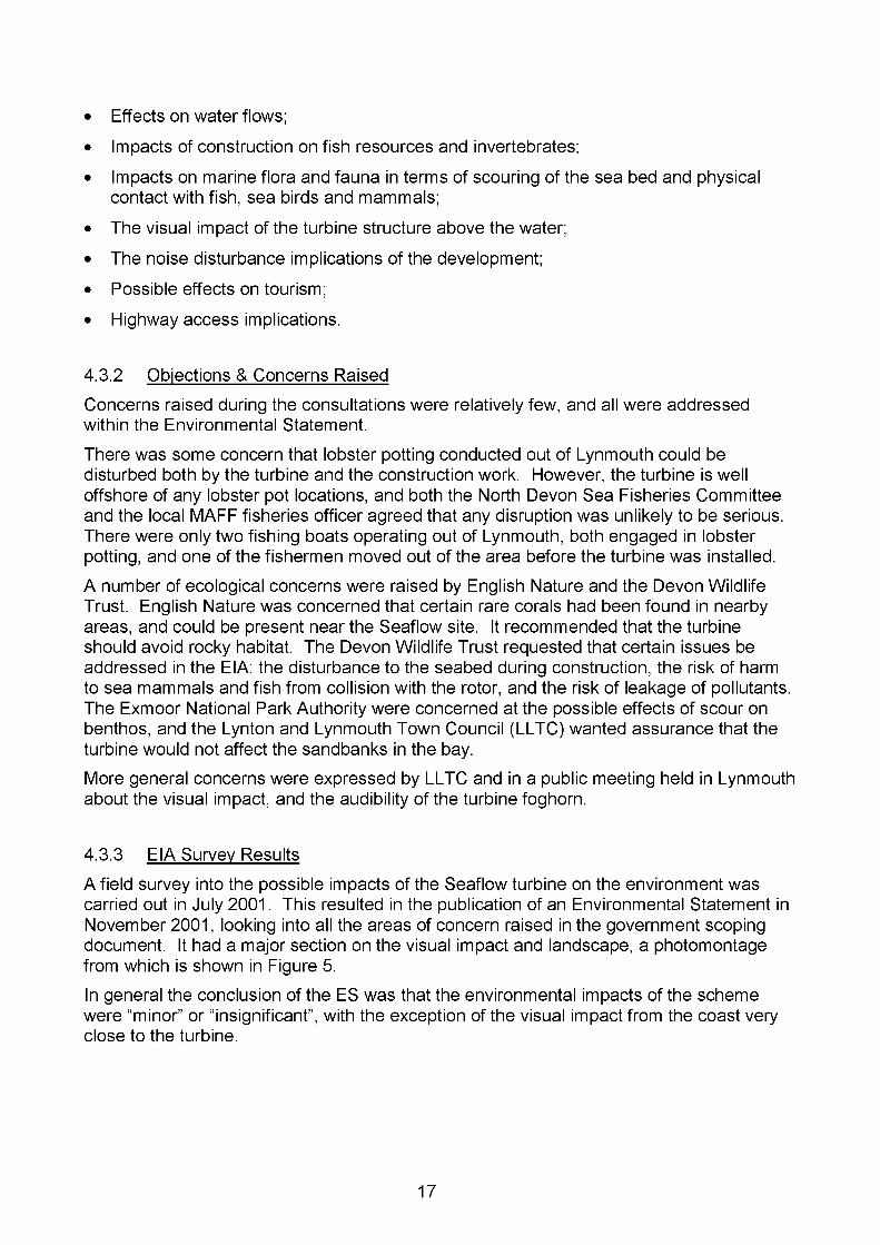
5. DESCRIPTION OF THE TURBINESeaflow resembles a wind turbine, but with the rotor totally submerged in seawater when working. It has a 2-bladed, horizontal-axis rotor, 11m in diameter. The rotor is directly mounted onto the shaft of a speed-increasing gearbox, which in turn drives a generator. The rotor is turned by the flow of water, and the generator produces electric power. The orientation of the rotor is fixed, but the blades can be pitched through 180° so that it can be used for currents in both directions, either on the ebb or the flood tide. As installed, the Seaflow rotor points up the Bristol Channel, facing directly into the ebb tide.The turbine is mounted on a steel tube or “monopile” which is fixed into the seabed. The powertrain (rotor, gearbox and generator) is mounted on a collar which can slide up and down the pile. With the collar out of the water, there is easy access to the working components for inspection and maintenance. Apart from the powertrain, all the other systems are housed in a ‘pod’ on the top of the pile. This means they can be kept in a controlled, dry environment, which is especially important for the electrical and control components.
5.1 Concept Design
The basic principles of the Seaflow concept were:
• It would be mounted on a monopile, giving a stable platform both to operate the machine and to access it.
• No divers or underwater operations should be required at any point in the life of the machine. Servicing would be by sliding the collar holding the powertrain up the pile and out of the water using a hydraulic lifting mechanism integral to the turbine.
• Access should be by small boat or RIB (Rigid Inflatable Boat).
• Only the powertrain would be submerged. All the control and power electronics to be housed in a control pod on the top of the pile, in the dry.
10 A Scoping Study for an Environmental Impact Field Programme in Tidal Current Energy; Centre for Environmental Engineering and Sustainable Development, Robert Gordon University; ETSU T/04/00213/REP, DTI Pub/URN 02/882; 2002.
19
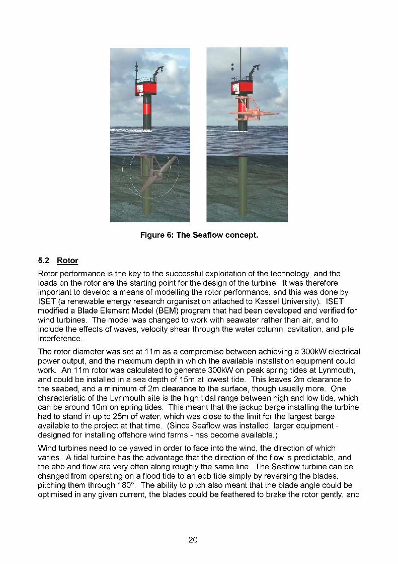
Figure 6: The Seaflow concept.
5.2 Rotor
Rotor performance is the key to the successful exploitation of the technology, and the loads on the rotor are the starting point for the design of the turbine. It was therefore important to develop a means of modelling the rotor performance, and this was done by ISET (a renewable energy research organisation attached to Kassel University). ISET modified a Blade Element Model (BEM) program that had been developed and verified for wind turbines. The model was changed to work with seawater rather than air, and to include the effects of waves, velocity shear through the water column, cavitation, and pile interference.The rotor diameter was set at 11 m as a compromise between achieving a 300kW electrical power output, and the maximum depth in which the available installation equipment could work. An 11m rotor was calculated to generate 300kW on peak spring tides at Lynmouth, and could be installed in a sea depth of 15m at lowest tide. This leaves 2m clearance to the seabed, and a minimum of 2m clearance to the surface, though usually more. One characteristic of the Lynmouth site is the high tidal range between high and low tide, which can be around 10m on spring tides. This meant that the jackup barge installing the turbine had to stand in up to 25m of water, which was close to the limit for the largest barge available to the project at that time. (Since Seaflow was installed, larger equipment - designed for installing offshore wind farms - has become available.)Wind turbines need to be yawed in order to face into the wind, the direction of which varies. A tidal turbine has the advantage that the direction of the flow is predictable, and the ebb and flow are very often along roughly the same line. The Seaflow turbine can be changed from operating on a flood tide to an ebb tide simply by reversing the blades, pitching them through 180°. The ability to pitch also meant that the blade angle could be optimised in any given current, the blades could be feathered to brake the rotor gently, and
20

the maximum power generated could be limited by angling the blades away from the optimum position. It was therefore decided to implement full-length blade pitch control.The choice of two blades was made after considering both 2 and 3-blade options. Rotors with three blades have the advantage of being slightly more efficient, and they are also more balanced, inducing less fatigue load on the gearbox and the structure. However, 2- blade rotors are much more easy to handle, as they can be laid flat on the deck of a ship, and do not need to be raised so far to clear the water. This is likely to be an important consideration for commercial turbines, where easy removal and replacement of the powertrain will increase the availability of the machines. 2-blade rotors are more simple mechanically (with only two blades, two pitch drive mechanisms etc), and are therefore cheaper. For Seaflow it was also found that the dynamic interaction between the rotor and the structure was less for a 2-blade rotor. The blades are made of composite.
5.3 Powertrain & Electrical System
The rotor is mounted on the front flange of a gearbox, which steps up the speed to drive a generator. The gearbox has an epicyclic first stage, followed by two helical gear stages. The gearbox was designed and manufactured by the German partner Jahnel-Kestermann. The gearbox has a hollow main shaft to allow cables to be taken to the hub through a slipring unit, for instrumentation and the pitch control drives. The generator is asynchronous, and bolts directly onto a flange on the rear of the gearbox. Unlike in wind turbines, the gearbox and generator are not enclosed in a nacelle, but are out “in the open”, submerged in seawater.The electrical power from the generator is fed by cables up to the pod, where it is conditioned by a frequency converter. This turns the alternating current from the generator to direct current and back again, and allows the speed of the generator to be controlled.A marine current turbine would normally be connected via a submerged cable to the local electrical network on the shore. This option proved too expensive for Seaflow, with the cost of installing a submarine cable being very high for a single turbine. The cost could not have been recouped by selling the electricity, and no significant technical lessons would have been learned from putting in a cable. It was therefore decided to operate the turbine off-grid. The generated power is dissipated into a fan-cooled resistance heater. Running off-grid posed some problems for exciting the generator and providing backup power for ancillary systems, and a stand-alone power system consisting of a diesel generator, several battery banks and numerous inverters had to be provided. A schematic electrical system is shown in Figure 7.
5.4 Control System, Instrumentation & Communications
The turbine is controlled via an industrial PC in the pod, which is linked to all the systems involved in operating the turbine. The machine can be started automatically by the control PC, or manually by adjusting the parameters on a control screen.
It was decided to use a PC-based system in order to give maximum flexibility. Windows- based hardware is not as stable as dedicated controllers, but it does make it easy to change the control software. For a production machine, the resulting software could be converted into code to run on a PLC (Programmable Logic Controller).
21
drive train cable
3 kVA5 kVA
power pack0.6 kVAcooling 1.5 kVA
0.8 kVA FC control -230 V
230 V socket/light10 batteriesa 250 Ah
Diesel-Genset 10 kVA
foghorn
25 kVAnav. light>15 kVA
instrument.
control/com
690 V760 -1100 Vsquirrel cage induction gen. 450 kVA650 kW 4Q-IGBT frequency converter
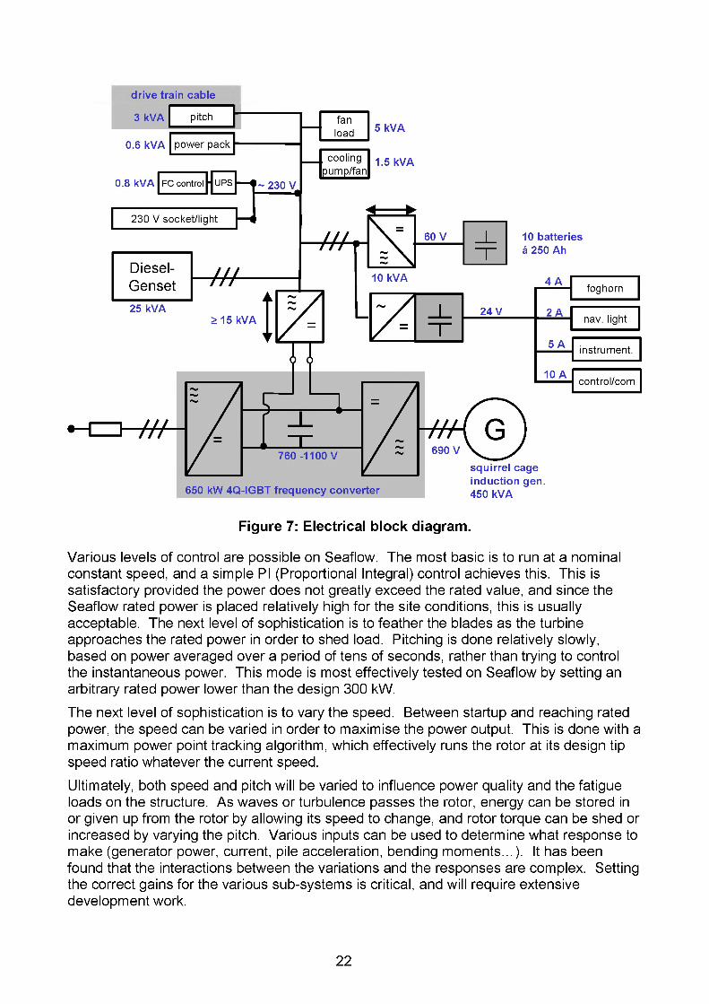
Figure 7: Electrical block diagram.
Various levels of control are possible on Seaflow. The most basic is to run at a nominal constant speed, and a simple PI (Proportional Integral) control achieves this. This is satisfactory provided the power does not greatly exceed the rated value, and since the Seaflow rated power is placed relatively high for the site conditions, this is usually acceptable. The next level of sophistication is to feather the blades as the turbine approaches the rated power in order to shed load. Pitching is done relatively slowly, based on power averaged over a period of tens of seconds, rather than trying to control the instantaneous power. This mode is most effectively tested on Seaflow by setting an arbitrary rated power lower than the design 300 kW.The next level of sophistication is to vary the speed. Between startup and reaching rated power, the speed can be varied in order to maximise the power output. This is done with a maximum power point tracking algorithm, which effectively runs the rotor at its design tip speed ratio whatever the current speed.Ultimately, both speed and pitch will be varied to influence power quality and the fatigue loads on the structure. As waves or turbulence passes the rotor, energy can be stored in or given up from the rotor by allowing its speed to change, and rotor torque can be shed or increased by varying the pitch. Various inputs can be used to determine what response to make (generator power, current, pile acceleration, bending moments...). It has been found that the interactions between the variations and the responses are complex. Setting the correct gains for the various sub-systems is critical, and will require extensive development work.
22

Area Measurement SensorEnvironment Current Magnetic meter
Water depth & waves Pressure transducerWind speed & direction Anemometer
Forces etc Blade bending moments & forces Blade strain gaugesPile bending moments & forces Pile strain gaugesPile movement Pile accelerometer
Operation Power, voltage, current etc Frequencyconverter
Pitch angle Rotary shaft encoders
Rotor position Shaft encoderCondition monitoring Gearbox oil & bearing temperature Temperature
sensorsGenerator winding & bearing Temperaturetemperature sensorsWater in hub Leakage sensors
Table 2: Main instrumentation
The Seaflow turbine is a prototype machine intended to advance the understanding of power extraction from tidal flows, and is therefore comprehensively instrumented; a list of the main instrumentation is given in Table 2. All data is passed to a data logger, which is linked to the control PC.Communications to the machine are via a radio link to a land base in Lynton. The onshore receiver is connected to a computer with a broadband connection, which allows the turbine to be accessed remotely over the internet. It is therefore possible to control and monitor the turbine from the shore, or from a modem anywhere else.
5.5 Structure & Foundation
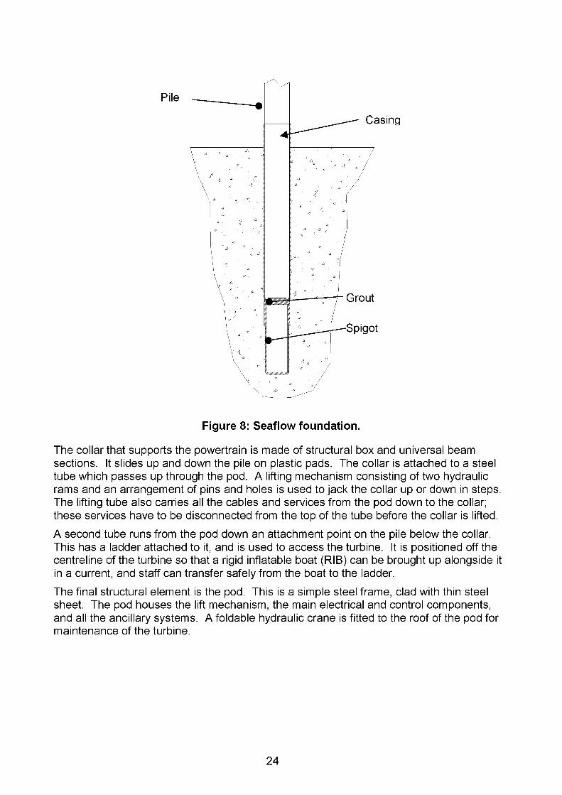
The main structural element of Seaflow is the tubular steel pile. This carries the weight of all the other components, the operating forces on the rotor, and the environmental loads.A maximum diameter and weight were imposed on the pile design by the capabilities of the jackup barge used to install it. Working within these limits, the pile was designed to carry all the loads with an acceptable life. The pile is a steel tube 2.1m in diameter, 42.5m long, and weighs 80 tonnes.Geotechnic information from the site indicated that there was sufficient strength in the seabed to drill a self-supporting hole, or "socket”, into which the pile could be grouted. However, an attempt to drill such a socket in September 2002 found the material to be locally fractured and weak such that it collapsed into the hole, and the attempt had to be abandoned. This led to a revision of the foundation design, with a steel casing being used to line the socket. A further spigot was inserted, as a precaution, into the seabed below the casing, to provide sufficient foundation strength for the apparently weak material. This arrangement was installed in the May 2003, and a good, strong foundation was achieved; it is possible that the first attempt was unfortunate in hitting a local weak spot.
23
Pile
Casing
Grout
Spigot
Figure 8: Seaflow foundation.
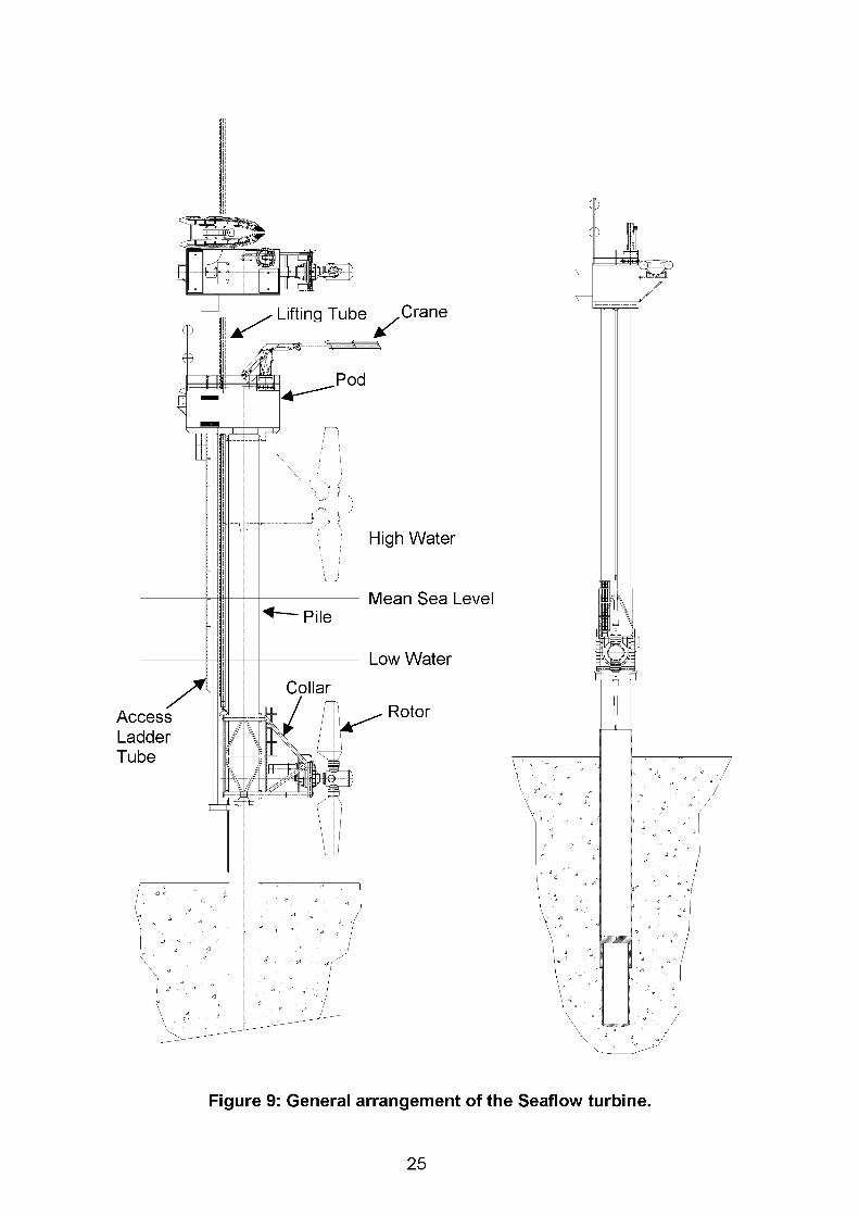
The collar that supports the powertrain is made of structural box and universal beam sections. It slides up and down the pile on plastic pads. The collar is attached to a steel tube which passes up through the pod. A lifting mechanism consisting of two hydraulic rams and an arrangement of pins and holes is used to jack the collar up or down in steps. The lifting tube also carries all the cables and services from the pod down to the collar; these services have to be disconnected from the top of the tube before the collar is lifted.A second tube runs from the pod down an attachment point on the pile below the collar. This has a ladder attached to it, and is used to access the turbine. It is positioned off the centreline of the turbine so that a rigid inflatable boat (RIB) can be brought up alongside it in a current, and staff can transfer safely from the boat to the ladder.The final structural element is the pod. This is a simple steel frame, clad with thin steel sheet. The pod houses the lift mechanism, the main electrical and control components, and all the ancillary systems. A foldable hydraulic crane is fitted to the roof of the pod for maintenance of the turbine.
24
mimiTimbd
Lifting Tube Crane
Pod
High Water
Mean Sea LevelPile
Low Water
CollarRotorAccess
LadderTube
Figure 9: General arrangement of the Seaflow turbine.
25

5.6 Access
The turbine is situated 3.5km from the nearest port. This is Lynmouth, which is small, and its harbour dries at low tide. It is suitable for small boats or RIBs. If a larger boat is required, this has to be brought from Ilfracombe or Appledore further west along the coast. It was only planned to use the jackup barge for installation and decommissioning.These considerations mean that it was planned to access the turbine using a RIB. It had to be possible to get onto the turbine in strong currents and moderate waves, otherwise the windows of access time would be very small, and it might take weeks or even months to get onto the pile. An access system has therefore been devised which uses a long ladder on a large diameter tube offset from the main pile. This goes outside the collar, and terminates on the underside of the pod. A RIB is brought alongside the pile, motoring against the current to hold it still. Staff then jump from the RIB onto the ladder and climb up into the pod.
5.7 Servicing
The turbine is designed so that as many operations as possible are conducted from on the pile, and that any exchange of parts can be done using a workboat. A jackup would only be required in an emergency if there was a failure of one of the main structural components: the collar, pod or pile.The crane on the roof of the pod has sufficient capacity to lift off each of the powertrain components separately, but not the whole powertrain as a single unit - which would require a very much larger crane. It has the capacity to service the collar lifting mechanism, and to lift components from within the pod on or off the turbine. It can also be used to manoeuvre a man basket to give access to the front of the rotor and hub when the collar is raised. A cover plate on the front of the hub can be removed from the man basket to get access to the pitch control.The collar is lifted using a mechanism similar to that employed for jack-up barge legs. This uses a pair of hydraulic rams to pull up a long tube attached to the collar. It works in steps, using two removable pins which engage with holes in a metal strip welded to the side of the tube. The power comes from a hydraulic pump attached to the backup generator diesel engine.Once the collar is up, dry access to it is via a second ladder fixed to the collar that comes up underneath the pod. There is a flat baseplate within the collar to allow movement around the powertrain.
5.8 Intellectual Property Rights (IPR), Patents
MCT has a policy of seeking to gain patent protection for key ideas stemming from its research programme. To this end it has secured eight UK patents so far (with several more applications in process) and several of the UK patents have been internationalised with versions granted in a number of foreign countries. The main topics covered by our patents are as follows:-
• A floating near neutral buoyancy device mounted under a moored floating raft with a mechanism for raising the turbine to the surface for maintenance (based on work carried out originally by IT Power in partnership with Scottish Nuclear and NEL on Loch Linnhe in 1994-5).
26
• A series of arrangements in which a turbine (or several turbines arranged side by side), generally with axial flow rotors, can be mounted on a monopile such that it/they can be raised above the surface for maintenance or repairs
• The use of full span active pitch control to permit a fixed axial flow rotor to operate efficiently in a bi-directional flow (using the flow from either direction) plus other methods of addressing bidirectional flow such as pitching the rotors either around a vertical axis or around a horizontal axis
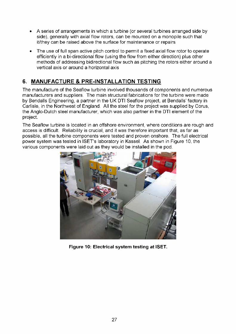
6. MANUFACTURE & PRE-INSTALLATION TESTINGThe manufacture of the Seaflow turbine involved thousands of components and numerous manufacturers and suppliers. The main structural fabrications for the turbine were made by Bendalls Engineering, a partner in the UK DTI Seaflow project, at Bendalls’ factory in Carlisle, in the Northwest of England. All the steel for the project was supplied by Corns, the Angle-Dutch steel manufacturer, which was also partner in the DTI element of the project.The Seaflow turbine is located in an offshore environment, where conditions are rough and access is difficult. Reliability is crucial, and it was therefore important that, as far as possible, all the turbine components were tested and proven onshore. The full electrical power system was tested in ISET’s laboratory in Kassel. As shown in Figure 10, the various components were laid out as they would be installed in the pod.
Figure 10: Electrical system testing at ISET.
27
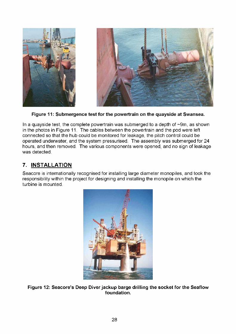
Figure 11: Submergence test for the powertrain on the quayside at Swansea.
In a quayside test, the complete powertrain was submerged to a depth of ~9m, as shown in the photos in Figure 11. The cables between the powertrain and the pod were left connected so that the hub could be monitored for leakage, the pitch control could be operated underwater, and the system pressurised. The assembly was submerged for 24 hours, and then removed. The various components were opened, and no sign of leakage was detected.
7. INSTALLATIONSeacore is internationally recognised for installing large diameter monopiles, and took the responsibility within the project for designing and installing the monopile on which the turbine is mounted.
Figure 12: Seacore s Deep Diver jackup barge drilling the socket for the Seaflowfoundation.
28

Tidal turbines present a challenge for offshore marine construction because of the need to work in water that is both deep and fast flowing; there is generally little call for construction work in such conditions. Currents impose significant drag loads on the legs of a jackup, and may also induce vibrations in the whole structure from vortex shedding off the round legs. Seacore undertook a number of detailed studies to assess these effects, and this led to modifications being made to the largest jackup barge Seacore then possessed, Deep Diver, to improve its strength and stability. Even so, Seacore had to impose limits on the operating envelope, which restricted both the depth in which the turbine could be installed, and hence the maximum rotor diameter. When Deep Diver was jacked up at the site, special farings were fitted to legs to lower the drag on them and to prevent any resonant vibrations due to vortex shedding; the top of these farings can be seen in Figure 12.The Seaflow turbine was installed over the period 9 April - 2 June 2003. This was longer than expected, but was extended by several periods of severe bad weather. Despite this, the jackup stood up well to the conditions, with no significant resonance or vibrations. A log of the main installation events is given in Table 3.
8 April 2003 Deep Diver jackup barge towed from Newport9 April Jackup position on site10 April Casing positioned17 April Main socket complete with casing in place18-21 April Some weather delays21 April Spigot socket drilled and spigot positioned22 April Spigot grouted.23-26 April Weather prevented pile being towed out during neap tides.27 April -9 May Work suspended awaiting next neap tide11 May Pile towed out to site and positioned in socket12 May Pile grouted into socket14 May Collar fitted to pile15 May Access tube and pod fitted16 May Lifting leg and maintenance crane fitted17 May Trial lowering/raising of collar19-26 May Work halted by weather27 May Powertrain fitted to collar29 May Collar and powertrain lowered into water30 May Maintenance crane tested and certified1 June Pile strain gauges calibrated2 June Deep Diver stepped away in good weather to allow easier towing3 June Deep Diver towed a few hundred metres away from Seaflow4 June Deep Diver left site
Table 3: Log of major installation events, April-June 2003
The foundation (see Figure 8) was made using a drill-drive technique to fix the casing into the seabed. In this way the installation method could cope with whatever ground conditions were found.With the casing in place, a smaller diameter socket was drilled for the foundation bottom spigot. The spigot was then fixed by holding it in the socket, and injecting grout into the space around it. Finally, the pile was lifted into the casing, and the annulus between it and the casing was also injected with grout.
29
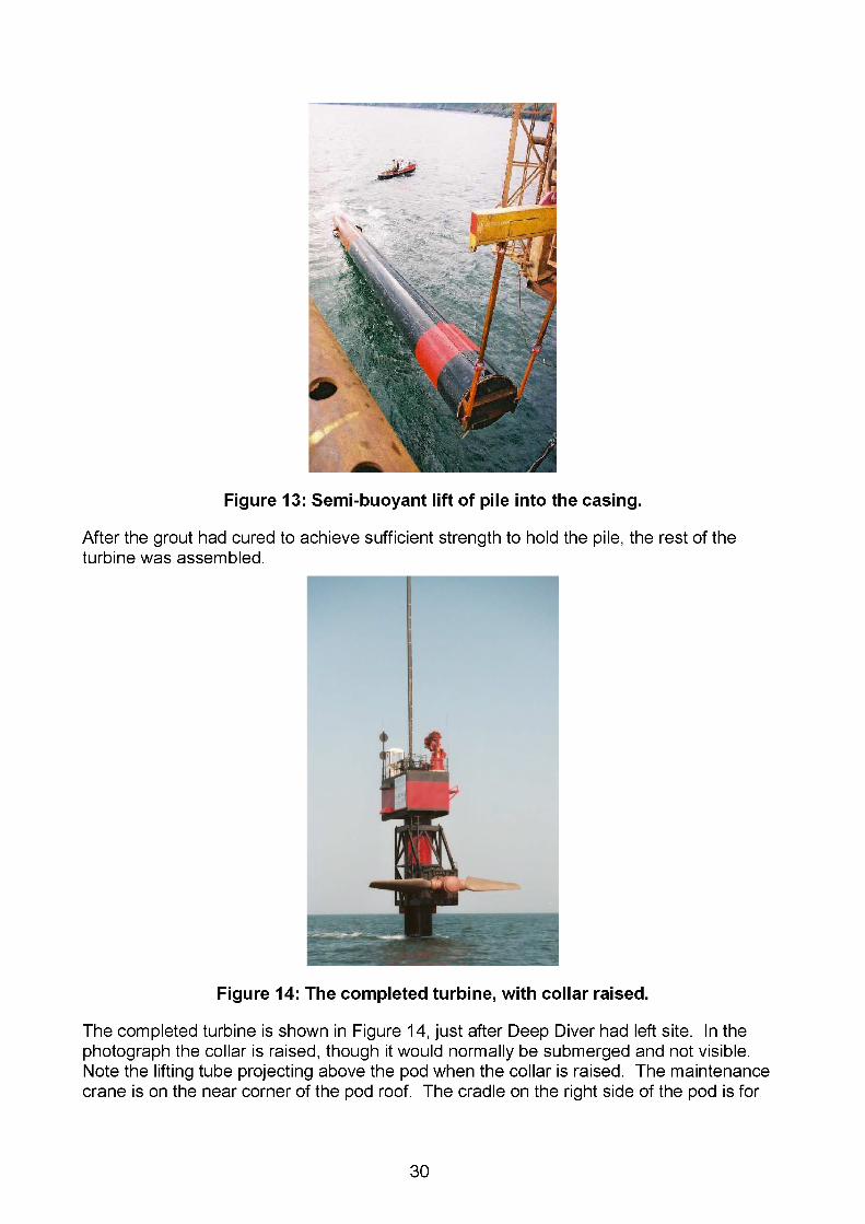
Figure 13: Semi-buoyant lift of pile into the casing.
After the grout had cured to achieve sufficient strength to hold the pile, the rest of the turbine was assembled.
Figure 14: The completed turbine, with collar raised.
The completed turbine is shown in Figure 14, just after Deep Diver had left site. In the photograph the collar is raised, though it would normally be submerged and not visible. Note the lifting tube projecting above the pod when the collar is raised. The maintenance crane is on the near corner of the pod roof. The cradle on the right side of the pod is for
30
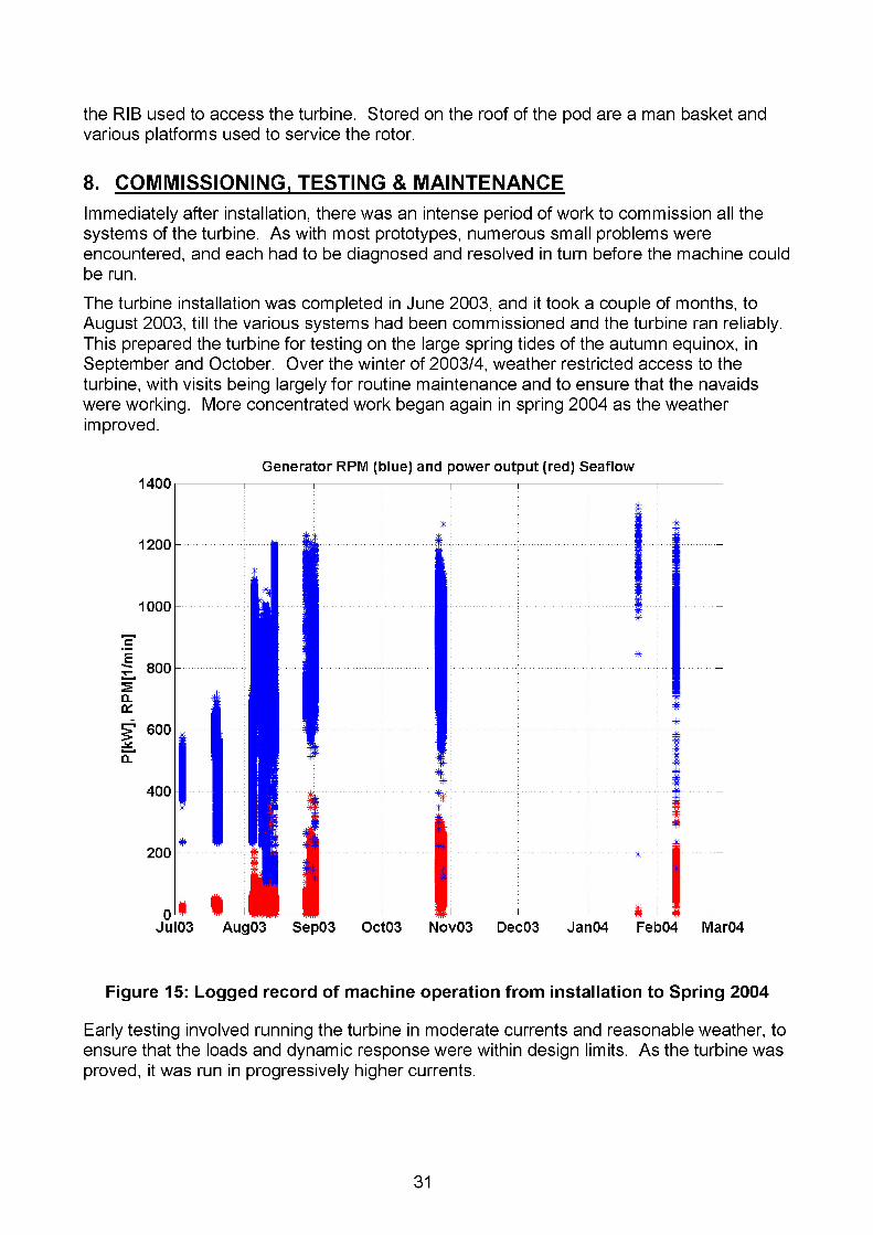
the RIB used to access the turbine. Stored on the roof of the pod are a man basket and various platforms used to service the rotor.
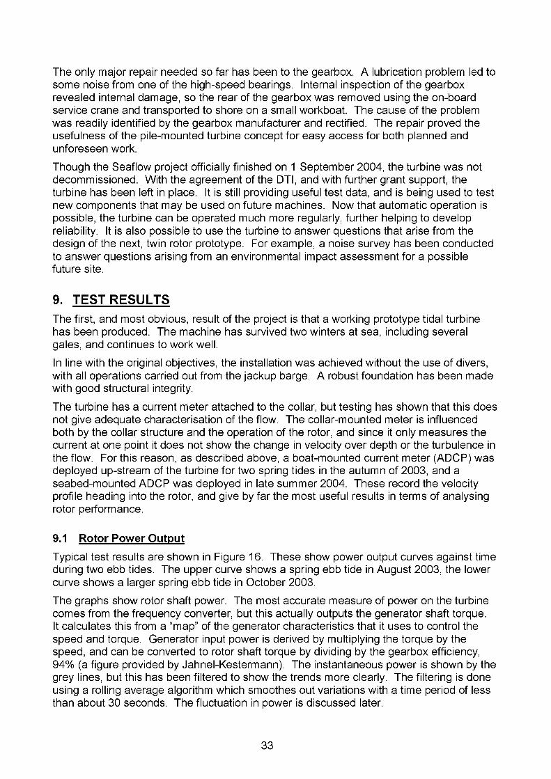
8. COMMISSIONING, TESTING & MAINTENANCEImmediately after installation, there was an intense period of work to commission all the systems of the turbine. As with most prototypes, numerous small problems were encountered, and each had to be diagnosed and resolved in turn before the machine could be run.The turbine installation was completed in June 2003, and it took a couple of months, to August 2003, till the various systems had been commissioned and the turbine ran reliably. This prepared the turbine for testing on the large spring tides of the autumn equinox, in September and October. Over the winter of 2003/4, weather restricted access to the turbine, with visits being largely for routine maintenance and to ensure that the navaids were working. More concentrated work began again in spring 2004 as the weather improved.
Generator RPM (blue) and power output (red) Seaflow1400
Jul03 Aug03 Sep03 Oct03 Nov03 Dec03 Jan04 Feb04 Mar04
Figure 15: Logged record of machine operation from installation to Spring 2004
Early testing involved running the turbine in moderate currents and reasonable weather, to ensure that the loads and dynamic response were within design limits. As the turbine was proved, it was run in progressively higher currents.
31

Initially, the turbine was mostly operated attended, with staff on the pod. During the first phase of the testing it was essential to have staff on the turbine, to gain familiarity with the device and to ensure that any significant problems could be rapidly identified and dealt with. Being present meant that operators had access to all the instrumentation, could hear the turbine and feel movements of the pile, and were present to resolve any problems that did occur. Development of automatic startup, and reliable safety systems to shut down the turbine if necessary, occupied much of good weather in 2004. By the end of the year it was possible to run the turbine remotely over the radio link.From installation to the end of 2004 the turbine was visited on 155 days, which represents a good proportion of the number of days on which weather allowed access. The turbine was run on 68 of those days. On 20 of these days the turbine was run through a full ebb tide, but the rest involved operation for short periods as the control system was developed and various components tested. Just over 80 operating hours were logged to the end of 2004.Attended operation restricted the number of hours for which the turbine can be run. Firstly, weather had to be suitable for access. Secondly the turbine is only routinely run on ebb tides, for reasons discussed below, and only one 6.5-hour ebb occurs in daylight per day; for safety reasons the turbine has rarely been visited at night. On a spring tide, the turbine runs for around 4 hours during the ebb (this is discussed in Section 9.3), and sometimes not at all on neaps. Hence the operating hours are low compared with what would be expected from a commercial machine.The turbine can be, and has been, run on both flood and ebb tides. On the ebb, the pile is behind the rotor, and flow entering the rotor is clean. The turbine can be operated on the flood, but the rotor is then in the wake of the pile. This reduces the power, but also imposes greater dynamic loads on both the blades and the structure. For future machines, it is planned that twin rotors will be mounted on a crossbeam (see Figure 20). This puts the rotors out of the pile wake, and the flattened crossbeam can be shaped to minimise the disturbance to the flow. Therefore, since operating in the pile wake is not of long term significance, the greater fatigue involved in running on flood tides has been avoided.For the two series of tests conducted in the autumn of 2003, a special current meter (an ADCP or Acoustic Doppler Current Profiler) was positioned on a boat ahead of the rotor, giving readings of current speed through the water column from the surface to the seabed. In August 2003 a seabed mounted ADCP was deployed some 50m upstream of the rotor (for ebb currents). This could log both currents and waves, and could be controlled through an underwater modem.The testing has generated large amounts of data, and has greatly improved the understanding of the functioning of the turbine. The results are discussed below in Section 9.Alongside the test programme, regular visits were made to the machine to ensure that everything was in good working order, to inspect the working components and structure, and to carry out both routine and necessary maintenance.Much of the work on the turbine has been development of systems and components. The marine environment is challenging, and leaks, condensation and corrosion have caused failures in many proprietary devices, even those supposedly designed for subsea use.The experience gained in solving these problems is invaluable, though it has been a long process to achieve some measure of reliability.
32
The only major repair needed so far has been to the gearbox. A lubrication problem led to some noise from one of the high-speed bearings. Internal inspection of the gearbox revealed internal damage, so the rear of the gearbox was removed using the on-board service crane and transported to shore on a small workboat. The cause of the problem was readily identified by the gearbox manufacturer and rectified. The repair proved the usefulness of the pile-mounted turbine concept for easy access for both planned and unforeseen work.Though the Seaflow project officially finished on 1 September 2004, the turbine was not decommissioned. With the agreement of the DTI, and with further grant support, the turbine has been left in place. It is still providing useful test data, and is being used to test new components that may be used on future machines. Now that automatic operation is possible, the turbine can be operated much more regularly, further helping to develop reliability. It is also possible to use the turbine to answer questions that arise from the design of the next, twin rotor prototype. For example, a noise survey has been conducted to answer questions arising from an environmental impact assessment for a possible future site.
9. TEST RESULTSThe first, and most obvious, result of the project is that a working prototype tidal turbine has been produced. The machine has survived two winters at sea, including several gales, and continues to work well.In line with the original objectives, the installation was achieved without the use of divers, with all operations carried out from the jackup barge. A robust foundation has been made with good structural integrity.The turbine has a current meter attached to the collar, but testing has shown that this does not give adequate characterisation of the flow. The collar-mounted meter is influenced both by the collar structure and the operation of the rotor, and since it only measures the current at one point it does not show the change in velocity over depth or the turbulence in the flow. For this reason, as described above, a boat-mounted current meter (ADCP) was deployed up-stream of the turbine for two spring tides in the autumn of 2003, and a seabed-mounted ADCP was deployed in late summer 2004. These record the velocity profile heading into the rotor, and give by far the most useful results in terms of analysing rotor performance.
9.1 Rotor Power Output
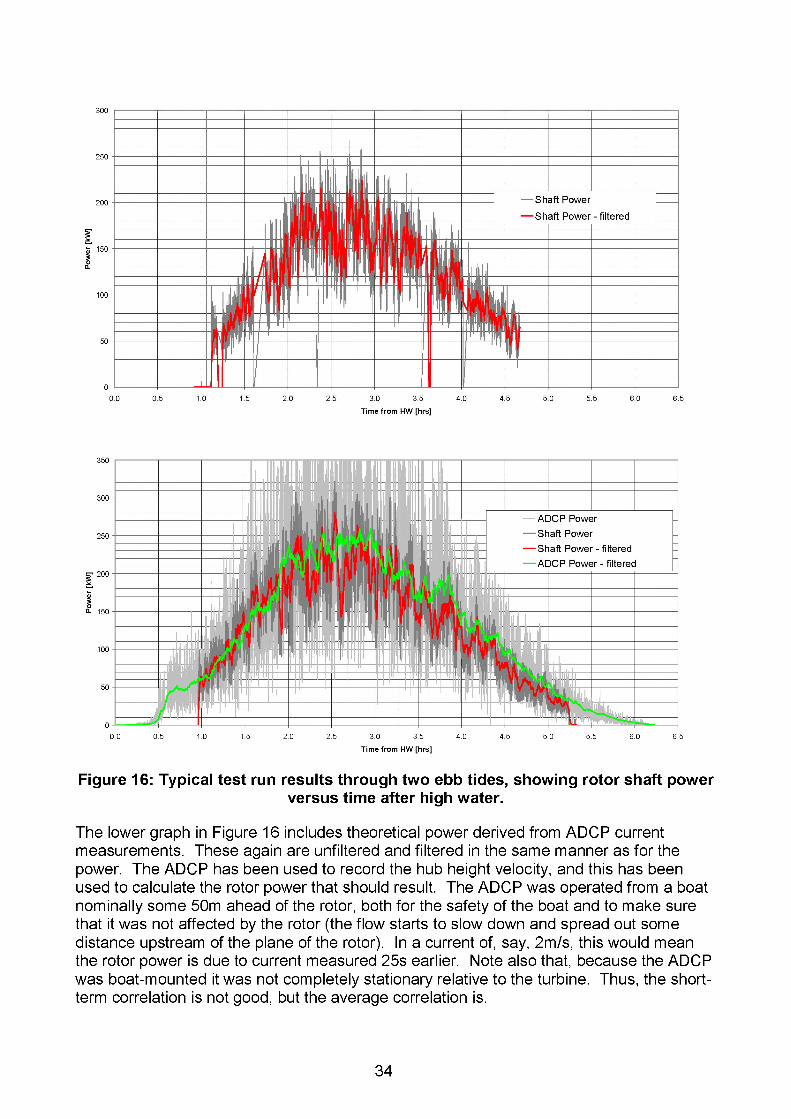
Typical test results are shown in Figure 16. These show power output curves against time during two ebb tides. The upper curve shows a spring ebb tide in August 2003, the lower curve shows a larger spring ebb tide in October 2003.The graphs show rotor shaft power. The most accurate measure of power on the turbine comes from the frequency converter, but this actually outputs the generator shaft torque.It calculates this from a “map” of the generator characteristics that it uses to control the speed and torque. Generator input power is derived by multiplying the torque by the speed, and can be converted to rotor shaft torque by dividing by the gearbox efficiency, 94% (a figure provided by Jahnel-Kestermann). The instantaneous power is shown by the grey lines, but this has been filtered to show the trends more clearly. The filtering is done using a rolling average algorithm which smoothes out variations with a time period of less than about 30 seconds. The fluctuation in power is discussed later.
33
300
250
200
| 150
£
100
50
Time from HW [hrs]
0 0 0.5 1 0 1 5 2.0 2.5 3.0 3.5 4.0 4.5 5.0 5.5 6.0 6.5
Time from HW [hrs]
Figure 16: Typical test run results through two ebb tides, showing rotor shaft powerversus time after high water.
The lower graph in Figure 16 includes theoretical power derived from ADCP current measurements. These again are unfiltered and filtered in the same manner as for the power. The ADCP has been used to record the hub height velocity, and this has been used to calculate the rotor power that should result. The ADCP was operated from a boat nominally some 50m ahead of the rotor, both for the safety of the boat and to make sure that it was not affected by the rotor (the flow starts to slow down and spread out some distance upstream of the plane of the rotor). In a current of, say, 2m/s, this would mean the rotor power is due to current measured 25s earlier. Note also that, because the ADCP was boat-mounted it was not completely stationary relative to the turbine. Thus, the shortterm correlation is not good, but the average correlation is.
34
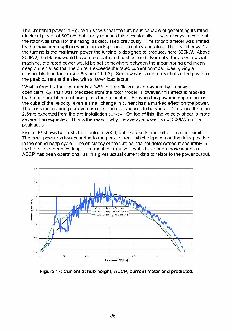
The unfiltered power in Figure 16 shows that the turbine is capable of generating its rated electrical power of 300kW, but it only reaches this occasionally. It was always known that the rotor was small for the rating, as discussed previously. The rotor diameter was limited by the maximum depth in which the jackup could be safely operated. The “rated power” of the turbine is the maximum power the turbine is designed to produce, here SOOkVV. Above 300kW, the blades would have to be feathered to shed load. Normally, for a commercial machine, the rated power would be set somewhere between the mean spring and mean neap currents, so that the current exceeds the rated current on most tides, giving a reasonable load factor (see Section 11.1.3). Seaflow was rated to reach its rated power at the peak current at the site, with a lower load factor.What is found is that the rotor is a 3-5% more efficient, as measured by its power coefficient, Cr, than was predicted from the rotor model. However, this effect is masked by the hub height current being less than expected. Because the power is dependent on the cube of the velocity, even a small change in current has a marked effect on the power. The peak mean spring surface current at the site appears to be about 0.1 m/s less than the 2.5m/s expected from the pre-installation survey. On top of this, the velocity shear is more severe than expected. This is the reason why the average power is not 300kW on the peak tides.Figure 16 shows two tests from autumn 2003, but the results from other tests are similar. The peak power varies according to the peak current, which depends on the tides position in the spring-neap cycle. The efficiency of the turbine has not deteriorated measurably in the time it has been working. The most informative results have been those when an ADCP has been operational, as this gives actual current data to relate to the power output.
Figure 17: Current at hub height, ADCP, current meter and predicted.
35
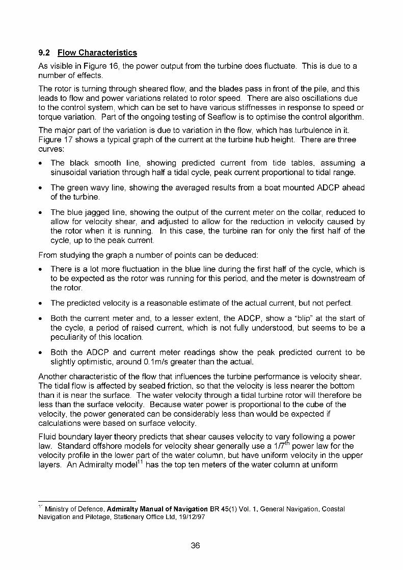
9.2 Flow Characteristics
As visible in Figure 16, the power output from the turbine does fluctuate. This is due to a number of effects.The rotor is turning through sheared flow, and the blades pass in front of the pile, and this leads to flow and power variations related to rotor speed. There are also oscillations due to the control system, which can be set to have various stiffnesses in response to speed or torque variation. Part of the ongoing testing of Seaflow is to optimise the control algorithm.The major part of the variation is due to variation in the flow, which has turbulence in it. Figure 17 shows a typical graph of the current at the turbine hub height. There are three curves:
• The black smooth line, showing predicted current from tide tables, assuming a sinusoidal variation through half a tidal cycle, peak current proportional to tidal range.
• The green wavy line, showing the averaged results from a boat mounted ADCP ahead of the turbine.
• The blue jagged line, showing the output of the current meter on the collar, reduced to allow for velocity shear, and adjusted to allow for the reduction in velocity caused by the rotor when it is running. In this case, the turbine ran for only the first half of the cycle, up to the peak current.
From studying the graph a number of points can be deduced:
• There is a lot more fluctuation in the blue line during the first half of the cycle, which is to be expected as the rotor was running for this period, and the meter is downstream of the rotor.
• The predicted velocity is a reasonable estimate of the actual current, but not perfect.
• Both the current meter and, to a lesser extent, the ADCP, show a “blip” at the start of the cycle, a period of raised current, which is not fully understood, but seems to be a peculiarity of this location.
• Both the ADCP and current meter readings show the peak predicted current to be slightly optimistic, around 0.1m/s greater than the actual.
Another characteristic of the flow that influences the turbine performance is velocity shear. The tidal flow is affected by seabed friction, so that the velocity is less nearer the bottom than it is near the surface. The water velocity through a tidal turbine rotor will therefore be less than the surface velocity. Because water power is proportional to the cube of the velocity, the power generated can be considerably less than would be expected if calculations were based on surface velocity.Fluid boundary layer theory predicts that shear causes velocity to vary following a power law. Standard offshore models for velocity shear generally use a 1/7th power law for the velocity profile in the lower part of the water column, but have uniform velocity in the upper layers. An Admiralty model11 has the top ten meters of the water column at uniform
11 Ministry of Defence, Admiralty Manual of Navigation BR 45(1) Vol. 1, General Navigation, Coastal Navigation and Pilotage, Stationary Office Ltd, 19/12/97
36
velocity, whereas design guidelines for the North Sea12 take half the water depth to be at uniform velocity.The right hand graph in Figure 18 shows various models at the Seaflow site. By chance, the Department of Energy North Sea Model is almost identical to the Admiralty model at this depth. These models are compared with a 1 /7th power boundary-layer profile from the surface to the seabed. Included is a 5-minute averaged measured curve near Seaflow. Measured curves have proved to be quite variable, but approximately fall between the models. Measured velocities near the bottom are not reliable because of scatter from the seabed.The left hand graph in Figure 18 shows the effect of shear on energy. Using a velocity profile with uniform flow to half depth, it can be seen that energy equivalent to the light grey shaded area is lost to the rotor due to the shear. With the high tidal range, and relatively shallow depth of the Seaflow site, the energy loss is quite significant.
Sea Surface
------ Surface------ 1 /7th power
DoE— -Admiralty ------ Measured
Velocity Profile
Flow Energy
Power density [kW/m2] Velocity [m/s]
Figure 18: The effect of velocity shear on the energy flow through the rotor.
The Seaflow test results obviously only examine one location. It is not clear whether these flow characteristics are generic, or whether other sites may be different. It is possible that other sites may be more uniform, but they could be more turbulent. Clearly, detailed survey work is required into the nature of current flow in a particular area before tidal turbines are installed.
12 UK Department of Energy, Offshore Installations: Guidance on Design, Construction & Certification,1990, page 11.35.
37

9.3 Rotor Performance & Energy Capture
It is simple to measure the power output of the turbine, but it is more difficult to discover the relationship of this to the current passing the turbine. The only tests that give a meaningful handle on this are those when an ADCP is present. As discussed previously, the correlation between the instantaneous power and current is difficult: the aDcp has to be situated some distance upstream of the rotor, and the time it takes to get to the rotor depends on the speed of the current itself. Large-scale turbulence may mean that the current the ADCP sees is not exactly what passes through the rotor. Deriving a performance coefficient for the rotor is therefore a matter of averaging.A standard way of measuring the performance of a horizontal axis rotor (as used for wind turbines) is to calculate the power coefficient, CP. This is the ratio of the actual power produced to the kinetic energy of a stream tube the same diameter as the rotor:
CPPro
t ^ %where p is the density of seawater, D is the rotor diameter, and V is the water velocity at the rotor centreline.The apparent, instantaneous, CP on Seaflow can vary from 0.2-0.6. When averaged it comes in the range 0.38-0.45, depending on the current. At higher currents - closer to the design operating point, the efficiency is better. The ISET rotor model predicted a CP towards the lower end of this range, so the rotor is performing better than expected.It should also be noted that the Seaflow rotor is by no means optimised. Rather, the foil sections, the chords and the twist were chosen primarily for ease of manufacture. It is expected that future rotors will be able to show higher efficiencies.
The energy captured over a given operating period can be calculated by integrating the power over this time. If this energy is compared with the average of the cube of the current, an alternative value of CP can be calculated. Over various cycles this comes out around 0.4, with better results in spring tides.It should be noted that CP is more critical in determining the output of Seaflow than it would be for future machines. Because Seaflow rarely reaches its rated power, it does not need to be feathered. Normally, a marine current turbine would only be required to operate at its best CP up to the rated current. Above this, the blades would be pitched to shed load, and so are intentionally operating at less than their best CP. Since the majority of energy would come from when the machine is at rated power, and the lower current operations generate a smaller proportion of the power, the rotor efficiency is not too critical to the performance of a turbine.The turbulence in the water means that the power generated fluctuates. The electrical control system on Seaflow allows the speed and torque of the generator to be varied, and this can be used to help smooth the output. By changing the "stiffness” of the speed response to changes, and varying the way in which power input signal is averaged, the size of the excursions from the nominal power can be reduced significantly, and some of the higher frequency components of the variation - up to a few seconds period - can be removed. The control system has to be set to balance power smoothing, reducing loads on the structure, and capturing the most energy. While some progress has been made, further testing is required to optimise the system.
38
10. EVALUATION OF OPERATIONSSeaflow is a research project, and the aim of building a prototype marine current turbine was to learn both how such a machine would perform and how such an installation might best be achieved. While the fundamentals of the machine concept have not altered, many aspects of the design have changed during the course of the project, as the partners have learnt what is and what is not possible, and discovered better ways of achieving the end results. The sections below describe various lessons learned during the project.
10.1 Turbine Design
10.1.1 Site ConditionsIt is not possible to tell yet how representative the Lynmouth site is of possible tidal turbine sites. It may be typical, but equally it may be that the flow conditions are different in different locations. It is clear that detailed site-specific surveys and modelling of currents will be required to determine flow regimes for future commercial machines.
10.1.2 Visual ImpactCompared with a wind turbine, Seaflow stands very low in the water. Nevertheless, it is clearly visible even from 3-4km away, and when seen from sea level it is quite noticeable, more so perhaps than photographs tend to indicate, as the eye is drawn towards it in an otherwise featureless sea. While the local people in and around Lynmouth have remained generally very supportive of the project, the only reservations expressed about developing from Seaflow to a farm of turbines on the site have been that the visual impact could be unacceptable.The Seaflow turbine has two disadvantages in this respect. Firstly, not being grid connected it has considerably more equipment in the pod than would be required normally, making the pod disproportionately large. Secondly, the tidal range of around 10m at that point in the Bristol Channel means that the turbine stands 15-20m above the water at low tide, which is higher than would be the case for most other sites. Nevertheless, it is clear that future machines must be made as unobtrusive as possible.
10.1.3 Pitch ControlFull blade pitch control was used successfully. This allows the turbine to respond to the change in current direction between ebb and flow by pitching 180°, and it provides a smooth, gentle way of braking the rotor. In addition, it allows the pitch to be adjusted for optimal performance over a range of current speeds, and can be used to accurately limit the load when the current exceeds the rated value.
10.1.4 Marine GrowthThe rotor blades are protected with a proprietary anti-foul paint that contains particles of copper in an epoxy base. This develops a thin oxide coating which sloughs off if any growth tries to attach to it. The rotor hub has lower specification copper-based anti-foul paint coating. Both have proved effective to date, with no signs of marine growth. From
39
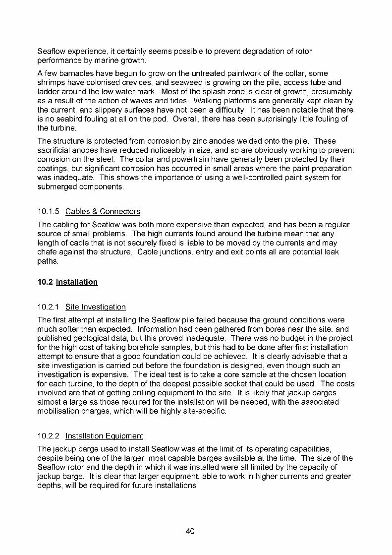
Seaflow experience, it certainly seems possible to prevent degradation of rotor performance by marine growth.A few barnacles have begun to grow on the untreated paintwork of the collar, some shrimps have colonised crevices, and seaweed is growing on the pile, access tube and ladder around the low water mark. Most of the splash zone is clear of growth, presumably as a result of the action of waves and tides. Walking platforms are generally kept clean by the current, and slippery surfaces have not been a difficulty. It has been notable that there is no seabird fouling at all on the pod. Overall, there has been surprisingly little fouling of the turbine.The structure is protected from corrosion by zinc anodes welded onto the pile. These sacrificial anodes have reduced noticeably in size, and so are obviously working to prevent corrosion on the steel. The collar and powertrain have generally been protected by their coatings, but significant corrosion has occurred in small areas where the paint preparation was inadequate. This shows the importance of using a well-controlled paint system for submerged components.
10.1.5 Cables & ConnectorsThe cabling for Seaflow was both more expensive than expected, and has been a regular source of small problems. The high currents found around the turbine mean that any length of cable that is not securely fixed is liable to be moved by the currents and may chafe against the structure. Cable junctions, entry and exit points all are potential leak paths.
10.2 Installation
10.2.1 Site InvestigationThe first attempt at installing the Seaflow pile failed because the ground conditions were much softer than expected. Information had been gathered from bores near the site, and published geological data, but this proved inadequate. There was no budget in the project for the high cost of taking borehole samples, but this had to be done after first installation attempt to ensure that a good foundation could be achieved. It is clearly advisable that a site investigation is carried out before the foundation is designed, even though such an investigation is expensive. The ideal test is to take a core sample at the chosen location for each turbine, to the depth of the deepest possible socket that could be used. The costs involved are that of getting drilling equipment to the site. It is likely that jackup barges almost a large as those required for the installation will be needed, with the associated mobilisation charges, which will be highly site-specific.
10.2.2 Installation EquipmentThe jackup barge used to install Seaflow was at the limit of its operating capabilities, despite being one of the larger, most capable barges available at the time. The size of the Seaflow rotor and the depth in which it was installed were all limited by the capacity of jackup barge. It is clear that larger equipment, able to work in higher currents and greater depths, will be required for future installations.
40
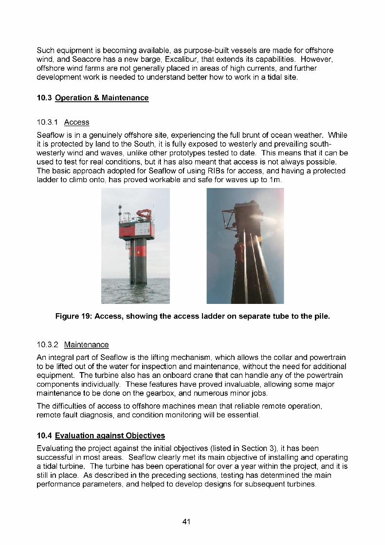
Such equipment is becoming available, as purpose-built vessels are made for offshore wind, and Seacore has a new barge, Excalibur, that extends its capabilities. However, offshore wind farms are not generally placed in areas of high currents, and further development work is needed to understand better how to work in a tidal site.
10.3 Operation & Maintenance
10.3.1 AccessSeaflow is in a genuinely offshore site, experiencing the full brunt of ocean weather. While it is protected by land to the South, it is fully exposed to westerly and prevailing southwesterly wind and waves, unlike other prototypes tested to date. This means that it can be used to test for real conditions, but it has also meant that access is not always possible. The basic approach adopted for Seaflow of using RIBs for access, and having a protected ladder to climb onto, has proved workable and safe for waves up to 1 m.
Figure 19: Access, showing the access ladder on separate tube to the pile.
10.3.2 MaintenanceAn integral part of Seaflow is the lifting mechanism, which allows the collar and powertrain to be lifted out of the water for inspection and maintenance, without the need for additional equipment. The turbine also has an onboard crane that can handle any of the powertrain components individually. These features have proved invaluable, allowing some major maintenance to be done on the gearbox, and numerous minor jobs.The difficulties of access to offshore machines mean that reliable remote operation, remote fault diagnosis, and condition monitoring will be essential.
10.4 Evaluation against Objectives
Evaluating the project against the initial objectives (listed in Section 3), it has been successful in most areas. Seaflow clearly met its main objective of installing and operating a tidal turbine. The turbine has been operational for over a year within the project, and it is still in place. As described in the preceding sections, testing has determined the main performance parameters, and helped to develop designs for subsequent turbines.
41

The process of installing and operating the machine has allowed techniques for installation and maintenance to be tried and developed. Only decommissioning remains untried, but this will have to be tackled at the end of work.The environmental impact of the turbine has been monitored in a number of ways, though much of this work was in the period following the end of the official Seaflow project period. An acoustic study has assessed the likely effect of turbine noise on marine life, and flow measurements have looked at the extent of the turbine wake.The project achieved most of its specific development targets. It reached its design power of 300kW, and achieved a CP of over 0.4. No divers have been used for the installation or maintenance. Marine growth has not occurred at all on the blades, and so there has been no associated performance loss. Cavitation has not been detected (either in acoustic tests or through its impact on performance), and there has been no cavitation damage to the blades.Only two of the targets have not been met. The turbine was more expensive than predicted, with an installed cost of £1,345,000 (see Section 11.1.1). The target of £900,000 was set before any detailed design work was done, and was clearly insufficient. The overspend was primarily on equipment and fabrications. There are special factors associated with making a first, one-off, relatively small machine, and the extrapolation of Seaflow costs to commercial machines is discussed in Section 11.It has also not been possible to operate the machine continuously for one month. As reported above, there have been many small problems with subsea wiring, backup power systems, instrumentation, as well a few more major maintenance tasks. It also took a long time to develop robust, safe, automatic control. While it has been possible to conduct series of detailed tests, more sustained testing has been limited. A major reason for keeping the turbine in operation to date is to steadily develop reliability, to add operating hours and to prolong periods of continuous operation.
11. COSTS
11.1 Seaflow Costs
The Seaflow project provides a reference point for the economics of tidal turbines, but in analysing it various qualifications have to be made. Seaflow is a first, one-off, prototype turbine. The total project costs include survey, permissions, design, development, installation and management costs that would normally be spread over many turbines. Installation overhead costs such as tooling, mobilisations, and weather allowance would normally be assigned to a farm of machines, not just one. Research and development costs would be applied to a particular design or model that would be used in numerous different sites over a number of years.The cost of electricity from tidal turbines has six main elements:
• Turbine quayside cost;• Installation cost;
• Energy produced;
• Operation and maintenance costs;
• Overheads such as site surveys, permissions;
42

• Cost of capital.The following sections breakdown of Seaflow cost into these headings, and assess how relevant the costs are for predicting the long-term economics of the technology.
11.1.1 Turbine Quayside CostsThe approximate machine costs for Seaflow are given in the first part of Table 4. This shows only the direct costs; that is, the cash costs of equipment and services and the direct labour costs involved in manufacture and installation. It does not include overhead and development costs such as staff time for design, development and project management.
Item Cost Notes
Hardware £845,000 Bought-out and manufacturing costs
Assembly & testing £100,000 Workshop staff, equipment
Total machine cost £945,000 £3150/kW
Installation £400,000 Jackup barge, materials
Total installed cost £1,345,000 £4480/kW
Table 4: Bought-out and direct costs of Seaflow
Commercial machines will need to be produced at a cost of ~£1000/kW or less, so the Seaflow cost of over £3000/kW is high. This is not unexpected, as all the parts are specials, bought as one-offs, and the prices are likely to include some development overheads and do not benefit from economies of series manufacture or multiple purchases. Also, 300kW is too small to be cost-effective, and future machines will be larger.
11.1.2 Installation CostsThe Seaflow installation cost is again relatively expensive. Commercial machines will need to be installed in 4-5 days, at a cost of £100,000-150,000 per machine. But this figure does not include mobilisation and tooling charges, which are part of the Seaflow cost. The Seaflow installation took longer than would be normal both because new techniques were being developed, and because a general-purpose construction jackup was being used, instead of a dedicated unit more suited for this application. As a result, the programme was extended by a requirement to utilise specific opportunities in the tidal and spring-neap cycles. There is considerable scope for reducing installation costs in future, as the volumes of turbines installed increases and investment in specialist equipment becomes viable. However, the development and capital cost of this equipment will be considerable.
11.1.3 Energy ProducedThe price of electricity is basically the number of units produced divided by the costs. Seaflow has shown that a horizontal-axis rotor operating in seawater does produce the power theoretical calculations predict, with levels of efficiency as discussed in Section 9.3.
43

If Seaflow is taken as typical these efficiencies can be applied to other turbines and sites to predict energy outputs.The modelling below has assumed a CP of 0.45, which is using the higher figures found on Seaflow for a rotor operating towards its design power. It is also expected that the Seaflow efficiency can be improved by a few percent by using a more optimised blade design. However, as mentioned before, the energy produced is not very sensitive to the values of CP, as the turbine only operates at its maximum efficiency between start-up and rated power, which is the lower-energy part of the cycle. When the current is stronger, the blades are feathered to shed load, deliberately lowering the CP. In order to achieve reasonable load factors, the turbine has to operate frequently at its rated power.The power coefficient is a measure of the rotor power relative to the current at hub-height. The current velocity at this height tends to be lower than near the surface because of the drag of the seabed, or velocity shear, as discussed in Section 9.2. Rotor power is very sensitive to flow velocity, so velocity shear has a noticeable affect on the energy output. Because Seaflow is in a relatively shallow site, with the rotor quite close to the seabed, it experiences significant velocity reduction at hub height. The shear at Lynmouth does not follow exactly any of the common models, and is variable. It is not clear how typical the Seaflow site is in this respect of general tidal sites.Related to energy produced, it should be noted that there has been no degradation of the turbine’s performance over the period it has been installed. The anti-foul protection applied to the blades has been effective, and there is no marine growth on them. If fouling did occur the blades could be cleaned with a pressure wash, and the anti-fouling can be restored in planned 5-year services when the powertrain is taken to shore. Seaflow therefore gives some confidence that the energy produced will not reduce over time.
11.1.4 Operation & Maintenance CostsThe cost of operation and maintenance for Seaflow over a 15 month period after installation came to approximately £115,000 of bought-outs items and services (consumables, spare parts, boat hire...). If staff charges are included the total O&M cost rises to about £300,000. These figures represent annual costs of 7-18% of the installed cost. Such percentage figures need to be treated with caution, as a) the installed cost of Seaflow is high, and b) there has been far more intervention on Seaflow than would ever be expected on a commercial machine. Though the Seaflow O&M costs are high, this is really to be expected for a prototype, and the 3% of capital cost for O&M used in longer term calculations seems reasonable.
One reason the Seaflow maintenance charges are moderate is that it can be serviced without bringing in large and expensive machinery. Access for testing, fault diagnosis and minor maintenance is by RIB, which is relatively cheap. The largest equipment required for Seaflow following installation has been a workboat to carry out a heavier piece of equipment, but this was lifted on and off the turbine using the integral crane. A workboat can be hired for a few thousand pounds a day or less, and a RIB for a few hundred pounds, both figures including crew. The experience with windfarms has been that large lifting equipment is required for each machine on average about every five years13. For offshore windfarms this would mean bringing in a large jackup or service vessel, and the cost of such an operation can use several years’ normal maintenance budget. Jackups
13 Reliability, availability and maintenance aspects of large-scale offshore wind farms, a concept study; G. J. W. van Bussel, M. B. Zaaijer; Delft University of Technology; ~2001.
44
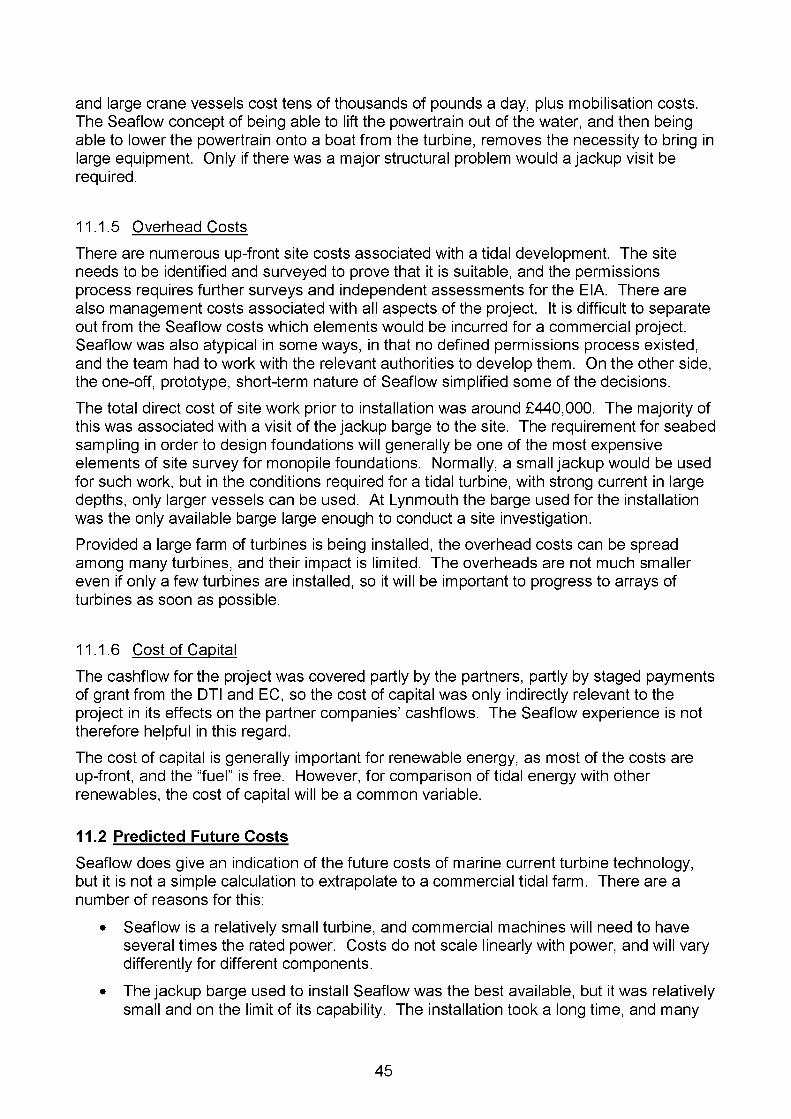
and large crane vessels cost tens of thousands of pounds a day, plus mobilisation costs. The Seaflow concept of being able to lift the powertrain out of the water, and then being able to lower the powertrain onto a boat from the turbine, removes the necessity to bring in large equipment. Only if there was a major structural problem would a jackup visit be required.
11.1.5 Overhead CostsThere are numerous up-front site costs associated with a tidal development. The site needs to be identified and surveyed to prove that it is suitable, and the permissions process requires further surveys and independent assessments for the EIA. There are also management costs associated with all aspects of the project. It is difficult to separate out from the Seaflow costs which elements would be incurred for a commercial project. Seaflow was also atypical in some ways, in that no defined permissions process existed, and the team had to work with the relevant authorities to develop them. On the other side, the one-off, prototype, short-term nature of Seaflow simplified some of the decisions.The total direct cost of site work prior to installation was around £440,000. The majority of this was associated with a visit of the jackup barge to the site. The requirement for seabed sampling in order to design foundations will generally be one of the most expensive elements of site survey for monopile foundations. Normally, a small jackup would be used for such work, but in the conditions required for a tidal turbine, with strong current in large depths, only larger vessels can be used. At Lynmouth the barge used for the installation was the only available barge large enough to conduct a site investigation.Provided a large farm of turbines is being installed, the overhead costs can be spread among many turbines, and their impact is limited. The overheads are not much smaller even if only a few turbines are installed, so it will be important to progress to arrays of turbines as soon as possible.
11.1.6 Cost of CapitalThe cashflow for the project was covered partly by the partners, partly by staged payments of grant from the DTI and EC, so the cost of capital was only indirectly relevant to the project in its effects on the partner companies’ cashflows. The Seaflow experience is not therefore helpful in this regard.The cost of capital is generally important for renewable energy, as most of the costs are up-front, and the “fuel” is free. However, for comparison of tidal energy with other renewables, the cost of capital will be a common variable.
11.2 Predicted Future Costs
Seaflow does give an indication of the future costs of marine current turbine technology, but it is not a simple calculation to extrapolate to a commercial tidal farm. There are a number of reasons for this:
• Seaflow is a relatively small turbine, and commercial machines will need to have several times the rated power. Costs do not scale linearly with power, and will vary differently for different components.
• The jackup barge used to install Seaflow was the best available, but it was relatively small and on the limit of its capability. The installation took a long time, and many
45

operations would be tackled differently with a larger, purpose built vessel with dedicated equipment. Future installations will have to balance the cost of investing in new installation equipment to achieve quick installations against using cheaper, existing machinery and taking somewhat longer.
• A knock-on effect of the limited depth in which the barge could operate was that the Seaflow rotor is smaller than ideal, limiting the energy capture. Future machines will have higher load factors.
• Seaflow is a one-off prototype, and the component costs were consequently high. There was no tooling or batch quantities to reduce costs.
• As a cooperative venture between partners, who were all contributing to the overall cost, the reported costs did not represent strict commercial rates.
• Seaflow is not grid connected, so gives no handle on the associated cost. It also contains a lot of equipment that would not be required for a grid-connected machine.
Nevertheless, Seaflow has shown that a working turbine can be achieved within a reasonable budget. The total project cost was less than that for any competitive full-scale prototype, even with a full year’s operation and maintenance. This demonstrates the simplicity of the concept, and the success of the design for low cost maintenance.Future costs can only be predicted at this stage with some form of techno-economic model that uses the Seaflow costs as a baseline, but makes realistic assumptions about scaling up the technology. As starting point for this has been the study into the commercial prospects of tidal stream power commissioned by DTI prior to funding Seaflow3. That study, by Binnie, Black and Veatch, represents an objective appraisal of the MCT concept. In what follows, the original study will be examined, and modified in the light of the Seaflow experience.The BBV study took as a baseline machine a twin-rotor (2 x 500kW) version of Seaflow, with two, horizontal-axis rotors mounted on a cross-arm which could slide up and down a surface-piercing monopile, installed by a jackup barge. A typical site was taken as having a depth of 30m, tidal range of 5m, and a mean spring peak current of 3m/s, requiring a rotor diameter of 15.9m. The report calculated the cost of electricity as 4.6-8.1p/kWh for a 5MW farm at current costs (depending on the discount rate chosen (5-15%), and 3.46.0p/kWh for a 30MW farm with some bulk production efficiencies. The report listed the most important development priorities for testing the assumptions it made as:
• rotor operation, efficiency and energy output;
• monopile design;
• monopile installation;
• offshore electrical equipment.The predicted future costs of the Seaflow-type technology can be examined by reevaluating the 2001 study in the light of the prototype.In the 2001 report, BBV checked the validity of a spreadsheet-based techno-economic model (TE model) generated by IT Power. Table 5 shows the major numerical assumptions made. The first data column gives the figures used in the IT Power TE model.
46
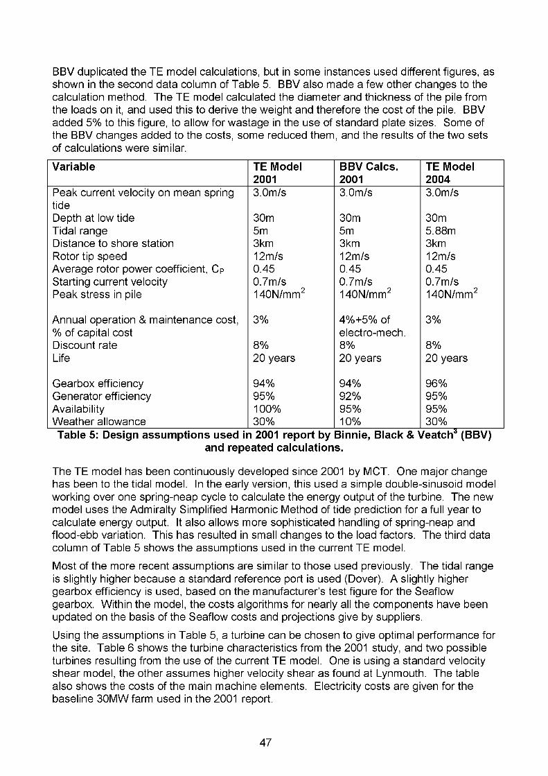
BBV duplicated the TE model calculations, but in some instances used different figures, as shown in the second data column of Table 5. BBV also made a few other changes to the calculation method. The TE model calculated the diameter and thickness of the pile from the loads on it, and used this to derive the weight and therefore the cost of the pile. BBV added 5% to this figure, to allow for wastage in the use of standard plate sizes. Some of the BBV changes added to the costs, some reduced them, and the results of the two sets of calculations were similar.
Variable TE Model2001
BBV Calcs.2001
TE Model2004
Peak current velocity on mean spring tide
3.0m/s 3.0m/s 3.0m/s
Depth at low tide 30m 30m 30mTidal range 5m 5m 5.88mDistance to shore station 3km 3km 3kmRotor tip speed 12m/s 12m/s 12m/sAverage rotor power coefficient, CP 0.45 0.45 0.45Starting current velocity 0.7m/s 0.7m/s 0.7m/sPeak stress in pile 140N/mm2 140N/mm2 140N/mm2
Annual operation & maintenance cost,% of capital cost
3% 4%+5% of electro-mech.
3%
Discount rate 8% 8% 8%Life 20 years 20 years 20 years
Gearbox efficiency 94% 94% 96%Generator efficiency 95% 92% 95%Availability 100% 95% 95%Weather allowance 30% 10% 30%Table 5: Design assumptions used in 2001 report by Binnie, Black & Veatch3 (BBV)
and repeated calculations.
The TE model has been continuously developed since 2001 by MCT. One major change has been to the tidal model. In the early version, this used a simple double-sinusoid model working over one spring-neap cycle to calculate the energy output of the turbine. The new model uses the Admiralty Simplified Harmonic Method of tide prediction for a full year to calculate energy output. It also allows more sophisticated handling of spring-neap and flood-ebb variation. This has resulted in small changes to the load factors. The third data column of Table 5 shows the assumptions used in the current TE model.Most of the more recent assumptions are similar to those used previously. The tidal range is slightly higher because a standard reference port is used (Dover). A slightly higher gearbox efficiency is used, based on the manufacturer’s test figure for the Seaflow gearbox. Within the model, the costs algorithms for nearly all the components have been updated on the basis of the Seaflow costs and projections give by suppliers.Using the assumptions in Table 5, a turbine can be chosen to give optimal performance for the site. Table 6 shows the turbine characteristics from the 2001 study, and two possible turbines resulting from the use of the current TE model. One is using a standard velocity shear model, the other assumes higher velocity shear as found at Lynmouth. The table also shows the costs of the main machine elements. Electricity costs are given for the baseline 30MW farm used in the 2001 report.
47
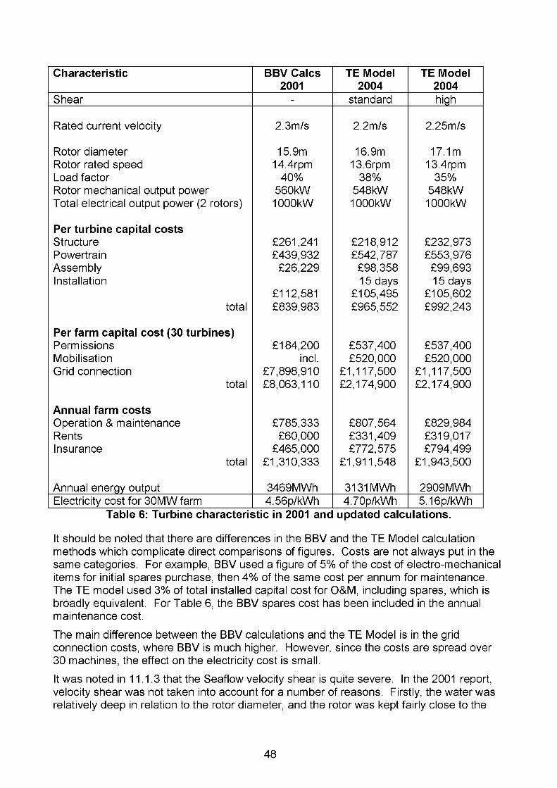
Characteristic BBV Calcs TE Model TE Model2001 2004 2004
Shear - standard high
Rated current velocity 2.3m/s 2.2m/s 2.25m/s
Rotor diameter 15.9m 16.9m 17.1mRotor rated speed 14.4rpm 13.6rpm 13.4rpmLoad factor 40% 38% 35%Rotor mechanical output power 560kW 548kW 548kWTotal electrical output power (2 rotors) 1000kW 1000kW 1000kW
Per turbine capital costsStructure £261,241 £218,912 £232,973Powertrain £439,932 £542,787 £553,976Assembly £26,229 £98,358 £99,693Installation 15 days 15 days
£112,581 £105,495 £105,602total £839,983 £965,552 £992,243
Per farm capital cost (30 turbines)Permissions £184,200 £537,400 £537,400Mobilisation incl. £520,000 £520,000Grid connection £7,898,910 £1,117,500 £1,117,500
total £8,063,110 £2,174,900 £2,174,900
Annual farm costsOperation & maintenance £785,333 £807,564 £829,984Rents £60,000 £331,409 £319,017Insurance £465,000 £772,575 £794,499
total £1,310,333 £1,911,548 £1,943,500
Annual energy output 3469MWh 3131MWh 2909MWhElectricity cost for 30MW farm 4.56p/kWh 4.70p/kWh 5.16p/kWh
Table 6: Turbine characteristic in 2001 and updated calculations.
It should be noted that there are differences in the BBV and the TE Model calculation methods which complicate direct comparisons of figures. Costs are not always put in the same categories. For example, BBV used a figure of 5% of the cost of electro-mechanical items for initial spares purchase, then 4% of the same cost per annum for maintenance. The TE model used 3% of total installed capital cost for O&M, including spares, which is broadly equivalent. For Table 6, the BBV spares cost has been included in the annual maintenance cost.The main difference between the BBV calculations and the TE Model is in the grid connection costs, where BBV is much higher. However, since the costs are spread over 30 machines, the effect on the electricity cost is small.It was noted in 11.1.3 that the Seaflow velocity shear is quite severe. In the 2001 report, velocity shear was not taken into account for a number of reasons. Firstly, the water was relatively deep in relation to the rotor diameter, and the rotor was kept fairly close to the
48
surface. This meant the hub was situated in, or close to, the uniform flow layer, and did not suffer a noticeable velocity reduction. Secondly, the mean spring velocities for sites were taken from tidal diamonds on Admiralty charts. These give velocities 5m below the sea surface, so if there were any velocity shear it would already be partly taken into account.In re-running the calculations, two scenarios were taken. One was to use the standard North Sea model for shear, with the results shown in the second column of Table 6. The second was to assume greater shear, similar to that found at Lynmouth, in the third column of Table 6. Site survey work conducted by MCT at other locations indicates that the Seaflow velocity shear is severe, and that a typical site is likely to lie between these two scenarios.The more sophisticated modelling does reduce the load factors, and velocity shear means that slightly larger rotors are required. Nevertheless, the costs of electricity are still reasonable.The future economics of the technology will be dominated by the rate at which the capital cost can be reduced, and by keeping down the operating costs thereafter.
12. FUTURE WORK
12.1 Further Development Work on Seaflow
Though the DTI Seaflow project officially finished on 1 September 2004, testing work has continued on the turbine, and there is no plan to decommission it before 2006. It remains an extremely useful testbed. Future work will be:
• To develop the reliability of the turbine so that it can be operated for ever longer periods unattended.
• To refine the control algorithms, as discussed in Section 5.4, to optimise energy production, to smooth power production, and to control extreme excursions of both power and structural loads.
• To improve the accuracy of the computer model of the turbine, and the effects of turbulence and waves.
• To continue to monitor the environmental impact, and conduct further tests on noise and flow effects.
12.2 Technology Development
Marine Current Turbines Ltd (MCT) was originally set up by IT Power to take over the commercial development of the Seaflow technology at the end of the project. MCT is now an independent company, and has raised investment capital to take forward the work. Among its shareholders are two utilities, EdF Energy and Guernsey Electricity, the Danish venture capital group BankInvest, and the Seaflow partners Seacore and Bendalls Engineering.MCT is already working on the design of a twin-rotor 1MW turbine. A potential site within the UK has been identified, and work is underway to obtain the permissions necessary to install the turbine. The DTI is again supporting this project. It is planned to put the machine in the water in 2006. This turbine is to be the precursor of commercial machines.
49

Following on from the twin-rotor prototype, MCT plans to install a commercial demonstration tidal farm, with multiple turbines and a total power output of between 1015MW. This will give some economies of scale, but also allow for field testing of the effects of an array on interaction between turbines, and the larger scale effects of arrays.The first farm will be followed by others, initially in the range 10-30MW, developed between 2007-2010. These will ideally be on sites that are capable of further development.
12.3 Installation Development
Seaflow has proved that a jackup barge provides an excellent platform for the installation of a tidal turbine. The ability to sit on site, fixed to the seabed, can potentially make operations independent of the weather, allowing quick progress.However, the development of installation methods and equipment will need to be run in parallel with the development of the technology. Seaflow was restricted by the limited depth and current capabilities of existing jackup barges. Larger vessels are becoming available, but the marine construction industry currently lacks equipment for the depths, tides and exposed locations that will need to be tackled for the longer term deployment of MCTs.Most existing work for marine construction is in ports or near-shore coastal waters. It is unusual to work in strong tides, and there is never the need to work in both strong currents and large depths. The work also varies from project to project, so the machinery has to be general purpose, adaptable to a wide range of operations and situations. This makes it less suitable, slower, and therefore more expensive than dedicated tidal turbine installation equipment would be.Installation development needs to pursue two main tracks: the creation of design tools and the development of equipment.Working in deep, fast-moving currents challenges both the stability of a jackup and the strength of its structure. Special studies had to be undertaken for Seaflow to ascertain that there was sufficient safety margin against slippage, bending of legs, or resonant vibration of the structure due to vortex shedding. There are no directly applicable design guidelines for these cases, and new methods had to be developed.This is not simply a case of giving the installer confidence that the machinery is safe. The need to obtain liability insurance for operations means that there have to be accepted design tools and criteria against which jackups can be certified.Larger jackup barges will definitely be necessary. Existing equipment can only work in depths of up to ~30m in still water. Development will also be needed for pile handling and assembly so that components can be worked with even in poor weather conditions and with fewer tidal and spring-neap cycle limitations.Some equipment is becoming available for offshore wind construction, such as Seacore’s barge Excalibur and the Mayflower Resolution. These go part of the way towards meeting the needs of tidal turbine, and begin to extend the range of conditions into which MCTs can be installed, but they are not ideal. In order to reduce the time and cost of installing piles and assembling turbines, dedicated jackups will be required.A difficulty here is that equipment development is expensive, and there needs to be a definite volume of work before construction companies can invest in it. At present there
50
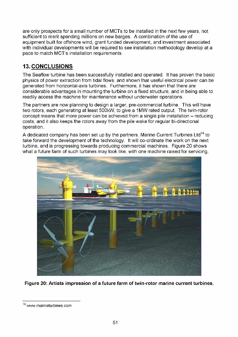
are only prospects for a small number of MCTs to be installed in the next few years, not sufficient to merit spending millions on new barges. A combination of the use of equipment built for offshore wind, grant funded development, and investment associated with individual developments will be required to see installation methodology develop at a pace to match MCT’s installation requirements.
13. CONCLUSIONSThe Seaflow turbine has been successfully installed and operated. It has proven the basic physics of power extraction from tidal flows, and shown that useful electrical power can be generated from horizontal-axis turbines. Furthermore, it has shown that there are considerable advantages in mounting the turbine on a fixed structure, and in being able to readily access the machine for maintenance without underwater operations.The partners are now planning to design a larger, pre-commercial turbine. This will have two rotors, each generating at least 500kW, to give a 1 MW rated output. The twin-rotor concept means that more power can be achieved from a single pile installation - reducing costs, and it also keeps the rotors away from the pile wake for regular bi-directional operation.A dedicated company has been set up by the partners, Marine Current Turbines Ltd14 to take forward the development of the technology. It will co-ordinate the work on the next turbine, and is progressing towards producing commercial machines. Figure 20 shows what a future farm of such turbines may look like, with one machine raised for servicing.
Figure 20: Artists impression of a future farm of twin-rotor marine current turbines.
14 www.marineturbines.com
51

APPENDICES
APPENDIX 1.........................................................................................................................53LIST OF ABBREVIATIONS, GLOSSARY OF TERMS, ETC.......................................... 53
APPENDIX II........................................................................................................................54PARTNERSHIPS..............................................................................................................54
APPENDIX III.......................................................................................................................58CONSULTATIONS.......................................................................................................... 58
APPENDIX IV......................................................................................................................59SUMMARY ENVIRONMENTAL STATEMENT................................................................59
52

APPENDIX I
LIST OF ABBREVIATIONS, GLOSSARY OF TERMS, ETC
ADCPBathymetryBEMBenthosBMWi
Acoustic Doppler Current ProfilerThe topography of the seabedBlade Element Method, simplified calculation technique for turbines Seabed flora and fauna (cf. benthic)German Government Bundesministerium fur Wirtschaft und Arbeit
CetaceansCPA
(Federal Ministry of Economics and Labour, replacing BM Wirtschaft und Technologie)Whales, dolphins and porpoisesCoast Protection Act (CPA), UK, 1949: legislation covering environment and marine usage aspects of permission for construction at sea.
DEFRA Department for Environment, Food and Rural Affairs, UK (replaced MAFF, Ministry of Agriculture, Fisheries and Food)
DfT Department for Transport, UK (replaced DTLR, Department for Transport, Local Government and the Regions, which was DETR, Department for the Environment, Transport and the Regions))
DTIECEIA
Department for Trade and Industry, UKEuropean CommissionEnvironmental Impact Assessment
Elasmobranchs Cartilaginous fishes, the group of which includes sharks, rays and skatesESFEPA
Environmental StatementsFood and Environment Protection Act, UK, 1985: legislation covering navigational aspects of permission for construction at sea.
IEE-RE Institut fur Elektrische Energietechnik - Rationelle Energiewandlung, University of Kassel, Partner in EC Seaflow Project
IPRISET
Intellectual Property Rights: patents, copyright, etcInstitut fur Solare Energieversorgungstechnik, affiliate of University of Kassel, working with IEE-RE on the EC Seaflow Project
ITPJa)(KeLAT
IT Power, Co-ordinator of the EC & DTI Seaflow Projects Jahnel-Kestermann, partner in the EC Seaflow ProjectLowest Astronomical Tide, usually approximately the same as ChartDatum
MCTMCT LtdMSLNaRECNeap tides PLCRIB
Marine Current TurbineMarine Current Turbines Ltd, partner Seaflow ProjectMean Sea LevelNew and Renewable Energy Centre at Blyth, Northumberland, UKTides with minimum level change and speedsProgrammable logic controllerRigid Inflatable Boat
Spring tides Tides with maximum level change and speedsVelocity shear The reduction in current velocity away from the water surface due to the
friction of the seabed
53

APPENDIX II
PARTNERSHIPS
UK COMPONENTDevelopment, Installation and Testing of a Large-Scale Tidal Current Turbine. 1 June 2001 - 31 August 2004. Project supported by the UK Government through the Department of Trade and Industry, DTI.IT POWER LIMITED - “IT POWER”, CO-ORDINATOR
IT Power, Grove House, Lutyens Close, Chineham, Hampshire, RG24 SAG, UnitedKingdomTel.: +44 (0)1256 392700Fax: +44 (0)1256 392701Email: [email protected]: http://www. itpower. co.uk
Project contact: Anthony Derrick, Managing DirectorTelephone: +44 (0)1256 392716Email: [email protected]
IT Power is a renewable energy consultancy, with over 20 years’ experience covering most aspect of renewable energy, completing over 800 projects in almost 100 countries. IT Power has also undertaken a number of R&D programmes, including some of the pioneering early work in river-current and tidal turbines.Within Seaflow, IT Power was responsible for the management of the project, design, operation and testing.SEACORE LIMITED - “SEACORE”
Seacore Ltd., Lower Quay, Gweek, Helston, Cornwall, TR12 6UD, United KingdomTelephone: +44 (0)1326 221771Fax: +44 (0)1326 221553Email: [email protected]: http://www.seacore.co.uk
Project contact: Peter Clutterbuck, Construction Director Telephone: +44 (0)1326 222232Mobile: +44 (0)7768 843335Email: [email protected]
Seacore is a marine exploration and civil engineering contractor, specialising in site investigations and the installation of large-diameter monopiles. Seacore has installed several of the first offshore wind farms.Within Seaflow, Seacore was responsible for structural design, installation, and maintenance.
54

MARINE CURENT TURBINES LIMITED - “MCT”
MCT, The Court, The Green, Stoke Gifford, Bristol, BS34 8PD, United KingdomTelephone:Fax:Email:Website:
+44 (0)117 979 1888 +44 (0)117 906 6140 [email protected] http://www.marineturbines.com
Project contact: Jeremy Thake, Technical Manager
Telephone: +44 (0)117 906 6121Email: [email protected]
MCT was originally established by IT Power to take forward the development of the Seaflow technology to a commercial product, but has subsequently become completely independent. MCT’s shareholders include EOF Energy, Seacore and Bendalls Engineering. The partners have chosen to assign the know-how and IPR arising from the Seaflow project to MCT.Within Seaflow, MCT was responsible for design of the rotor, operation and testing.
BENDALLS ENGINEERING - “BENDALLS”
Bendalls Engineering, Albion Works, London Road, Carlisle, CA1 2PW, United KingdomTelephone: +44 (0)1228 526246Fax: +44 (0)1228 525634Email: [email protected]: http://www.bendalls.co.uk
Project contact: Norman Addison, Managing Director Email: [email protected]
Bendalls Engineering is part of Carrs Milling pic, and is a large steel fabricator. Bendalls has traditionally specialised in pressure vessels and nuclear plant fabrications, but is diversifying into renewable energy.
Bendalls undertook detailing and manufacture of the structural steel components, and the assembly of the pod and rotor.
CORUS CONSTRUCTION & INDUSTRIAL - “CORUS”
Corns Construction & Industrial, Commercial Centre, P.O. Box 1, Brigg Road, Scunthorpe, N. Lincolnshire, DN16 1BP, United KingdomTel.: +44 (0) 1724 405453Fax: +44 (0) 870 902 3156Email: CC&[email protected]: http://www.corusgroup.com
Project contact: Jon Williams, Business Development ManagerTelephone: +44 (01642) 404239Fax: +44(01642)404284Mobile: +44 (07802) 458353Email: [email protected]
55

Corns is a large, international steel company, with major manufacturing and research facilities.Within Seaflow, Corns supplied all the steel, and gave expert assistance on various aspects of the design.
EC COMPONENTSeaflow, The World’s First Pilot Project for the Exploitation of Marine Currents at a Commercial Scale. 1 September 1998 - 31 August 2003. Supported by the European Commission in the framework of the Non-Nuclear Energy Programme, JOULE III.IT POWER - CO-ORDINATOR
Also co-ordinator of the DTI project - see above.SEACORE
Also a partner in the DTI project - see above.UNIVERSITAET GESAMTHOCHSCHULE KASSEL, INSTITUT ELEKTRISCHE ENERGIETECHNIK, RATIONELLE ENERGIEWANDLUNG - “IEE-RE, GhK”
GhK, FB16, IEE-RE, Wilhelmshoeher Allee 73, D-32121 Kassel, GermanyWebsite: http://www.re.e-technik.uni-kassel.de
Project contact: Jochen Bard, Scientific Officer Telephone: +49 (0) 561 7294 346Fax: +49 (0) 561 7294 100Email: [email protected]
IEE-RE is a department of Kassel University that specialises in renewable energy research and teaching.Within Seaflow, IEE-RE was jointly responsible with ISET for the electrical, control and instrumentation systems.
56

JAHNEL-KESTERMANN - “Ja)(Ke”
Jahnel-Kestermann GmbH, Hunscheiderstr. 116, D-44789 Bochum, GermanyTelephone:Fax:Email:Website:
+49 (0)234 3390 +49 (0)234 339200 [email protected] http://www.iake-qear.com
Project contact: Dirk Haske, Produktmanagement Windenergie Telephone: +49 (0)234 339336Fax: +49 (0)234 339330Email: [email protected]
Jahnel-Kesterman is a specialist gearbox manufacturer, making large gearboxes for a variety of markets. It has experience of both the marine and renewable energy industries, and is increasingly involved in wind turbine gearbox manufacture.Ja)(Ke designed and manufactured the gearbox for Seaflow.Ja)(Ke replaced ITT Flygt as the partner responsible for the powertrain in Seaflow in 2001.
GERMAN COMPONENTControl and management of variable speed marine current turbines on variable-speed powertrains for tidal turbines. 1 March 2001 - 30 June 2004. Supported by the German Federal Government through the Energieforschung und Energietechnik (Fachprogramm) of the Bundesministerium fur Wirtschaft und Technologie, BMWi.INSTITUT FUR SOLARE ENERGIEVERSORGUNGSTECHNIK - “ISET”, CO-ORDINATOR
ISET, Kdnigstor 59, D-34119, Kassel, GermanyTel.: +49(0)561 7294 0Fax: +49 (0) 561 7294 100Email: [email protected]: http://www.iset.uni-kassel.de
Project contact: Jochen Bard, Scientific Officer Telephone: +49 (0) 561 7294 346Fax: +49 (0) 561 7294 100Email: [email protected]
ISET is a renewable energy research organisation associated with the University of Kassel.ISET was responsible with GhKforthe electrical, control and instrumentation systems in Seaflow.
57

APPENDIX III
CONSULTATIONS
The table below summarised the consultations undertaken before the Seaflow turbine was installed.
Consultee Date* Type**
Subject
Lynton & Lynmouth TownCouncil
18/8/9927/9/01
CM
General installation, local impact
Lynton & Lynmouth 27/9/01 M Public meetingNorth Devon District Council 9/3/99 C General installation, possible shore
crossing.Exmoor National Park 24/5/99 C
MGeneral installation. PlanningAuthority for possible cable route.
North Devon District Journal 31/1/02 C Public noticeDEFRA/MAFF 28/4/99 M FEPA authorityEnvironment Agency 21/9/98 C Statutory consultee for FEPA. Impact
on flow.English Nature, Maritime Team 4/3/99 C Marine impacts. Statutory consultee
for FEPA.National Trust 21/1/99 C Landscape impact from Foreland
Point, possible use of land for cable.Devon Wildlife Trust 24/2/99 C Effect on wildlifeNorth Devon Sea Fisheries Committee, NDSFC
23/7/02 T Impact on fishing.
Local fishermen 5/9/99 M Impact on fishing.CEFAS 28/4/99 M Statutory FEPA consulted.
Effect on fisheries.DfT/DETR 28/4/99 M CPA authorityMaritime & Coastguard Agency 6/10/98 C Location of turbine.Trinity House 17/8/01 C Navigational markings. Impact of
operations.Lynmouth Harbour Authority 24/1/02 C Navigation impacts.Ilfracombe Harbour Authority M Navigation impacts.The Crown Estate 25/10/9
9C Seabed owner
DTI 28/4/99 M Electricity Act authorityIlfracombe & North Devon SubAqua Club
4/9/99 T Possible effects of rotor on divers.
Greenpeace 9/3/01 M Environmental issuesNorth Devon Alternative Energy Group
18/7/00 C General interest
*Date of initial contact or meeting given; this often led to correspondence over an extended period.**M - meeting, C - correspondence, T - telephone conversation,
58

APPENDIX IV
SUMMARY ENVIRONMENTAL STATEMENT
59
CASELLA=STANGER
MARINE CURRENT TURBINES LTD. THE SEAFLOW PROJECT, OFF FORELAND
POINT, NORTH DEVON
ENVIRONMENTAL STATEMENT
NON-TECHNICAL SUMMARY
November 2001
Collated by Stewart Lowther Meem
Director of Ecology
Prepared for Marine Current Turbines Ltd2 Amherst Avenue Ealing London W13 8NQ
Document Ref: 08659.01.01/SL/R1/REV1 Our Ref: 086590101

CONTENTS
PAGEIntroduction 1Scope of Environmental Statement 1Description of the proposals 1Reasons for site selection ConsultationsDescription of the existing environment 3
PHYSICAL ENVIRONMENT 3BIOLOGICAL ENVIRONMENT 4LANDSCAPE AND SEASCAPE 5
Assessment of impacts 6PHYSICAL ENVIRONMENT 6BIOLOGICAL ENVIRONMENT 7LANDSCAPE AND SEASCAPE 7FISHERIES 8NAVIGATION 8
NOISE 8Data deficiencies 8Summary table 9
appendix: visual effects of the turbine structure
CM
CM

INTRODUCTION
1 Marine Current Turbines Ltd have applied for permission to construct and operate a prototype tidal electricity generator at Ordnance Survey Grid Reference SS75000 52165, off Foreland Point, North Devon.
2 The DETR (now DTLR) and MAFF (now DEFRA) indicated to the company that, under the terms of the Harbour Works (Environmental Impact Assessment) Regulations 1999 (the Regulations), and Environmental Impact Assessment (EIA) would be required.
3 Marine Current Turbines Ltd commissioned Casella Science and Environment Ltd (now trading as Casella Stanger Ltd) to carry out the EIA, and to prepare an Environmental Statement (ES) in July 2001.
4 This document is a non-technical summary of the ES. The ES comprises two volumes. Volume 1 contains the central findings of the EIA. Volume 2 contains appendices that support those findings.
SCOPE OF THE ES
5 The Regulations require an Environmental Statement to contain: a description of the proposals; an outline of the alternatives considered by the developer; a description of the parts of the environment that may be affected by the proposals; a description of those possible effects and the measures taken by the developer to avoid or reduce their significance. Finally, the ES should highlight any data discrepancies, or assumptions that may have been made during the EIA, and which may have affected the outcome of the process. A non-technical summary is also required by the Regulations.
6 The DETR advised the developer on the aspects of the environment likely to be affected by the proposals. This advice determined the investigations that were carried out as part of the EIA.
DESCRIPTION OF THE PROPOSALS
7 The Seaflow project is best demonstrated by illustration (see Figure 1).
8 The structure will be supported by a single steel monopile drilled into the sea bed. The generator will be turned by an 11m rotor with three blades, turned by the water flowing past the turbine.
9 Installation of the turbine will be carried out from a jack-up barge, which will be towed to the site. The barge will drill a socket into the sea bed, place the support tower into it, and grout it into place using an inert grouting material. The cuttings from the hole will be pebble-sized and will have a volume of approximately 75 cubic metres. They will be pumped to the surface and then discharged onto the sea bed from a pipe 10m below the surface. The construction period is expected to be around two weeks.
10 The turbine will operate for up to five years. As the turbine is a prototype, it will not be connected to the shoreline via a cable, and the power it generates will be dissipated into the air. At the end of the trial period, the turbine would be removed. The supporting monopile would be cut off at sea bed level and the cut section removed.
Report ref: 08659.01.01/SL/(Non-technical)Casella Science and Environment Ltd
1

II
Figure 1: Artist’s impression of theSeaflow Project
REASONS FOR SITE SELECTION11 Several potential sites were examined before a final selection was made. The
Foreland Point site was eventually selected because it meets the requirements for high current speeds, whilst at the same time was felt to present few problems to fisheries, navigation, or sensitive flora and fauna. In addition, the site is relatively close inshore and easily accessible, and thus suitable for the frequent monitoring of the prototype machine. Geophysical investigations carried out by the developer showed that the sea bed was suitable for supporting the turbine, and discussions with relevant third parties, including the Exmoor National Park Authority, and English Nature, raised no over-riding concerns.
CONSULTATIONS12 A broad range of third parties were consulted both prior to and during the EIA
process. The consultation exercise aimed to fulfil three purposes: to inform; to obtain information; and to hear any concerns, so that modifications to the design of the turbine could be made where possible.
13 Written views were received from the following:
• Lynton and Lynmouth Town Council
• North Devon District Council
• Trinity House Lighthouse Service
• The Crown Estate
IReport ref: 08659.01.01/SL/(Non-technical)Casella Science and Environment Ltd
2
• Maritime and Coastguard Agency
• North Devon Sea Fisheries Committee
• English Nature
• Devon Wildlife Trust
• Environment Agency
14 Meetings, attended by the developers and relevant Casella Stanger Ltd consultants, were held with:
• The Town Clark of Lynton and Lynmouth Town Council
• Representatives of the Exmoor National Park Planning Authority.
15 In addition, presentations were made by the developers and Casella Stanger to the Town Council of Lynton and Lynmouth, and to an open public meeting, attended by 27 interested parties including local residents.
16 Information provided by consultees was taken into account during the EIA process. Dialogue with third parties enabled the approach taken to specific aspects of the EIA (particularly the visual impacts) to be agreed at an early stage. Discussions during the process have enabled solutions to potential problems to be identified, where possible. The ES was therefore prepared in the light of the information and opinions of those consulted.
DESCRIPTION OF THE ENVIRONMENT
The Physical Environment
17 The marine current turbine is located on the seaward side of a depression that lies between Foreland Point and the underwater feature known as Foreland Ledge. The depression is approximately 700 metres long and has a floor around 100 metres wide. Water depths at the floor are between 20 -22 metres below chart datum (CD). The turbine is located on the northern slope of the depression, on the -15m CD contour.
18 The site is directly exposed to waves from west through north to east. The majority of waves are from the west and north west. The largest waves are from a WNW direction, although waves from further to the south, which are more subject to wind and swell, will also influence conditions at the site. Maximum wave heights can exceed 6 metres, although these are predicted to occur only extremely rarely (less than once every 100 years). By far the majority of waves at the turbine location (up to 92%) are less than one metre in height.
19 Tides within the Severn Estuary rise and fall twice a day. Data calculated for the Seaflow site show the mean high water spring tides to be 9.5m above chart datum, and mean low water spring tides to be 0.7m above CD, giving a spring tidal range of 8.8 metres. The neap tidal range is 4.4 metres.
20 Maximum tidal flows on both the ebb and flood tides are in an east to west direction. Maximum ebb currents are greater than maximum flood currents. Maximum current speeds are typically between 2.0 and 2.5 metres per second on spring tides. Current speeds of more than 1 metre per second persist for approximately 4.5 hours during the ebb tide flow, and for approximately 5 hours during the flood tide flow.
Report ref: 08659.01.01/SL/(Non-technical)Casella Science and Environment Ltd
3

21 The seabed on the site is generally hard and featureless, with less than 1 metre of deposits overlying the bedrock. In some natural gullies, for example, 1000 metres from the turbine site, up to 2 metres of sand cover can occur, with evidence of sand waves on the surface. The turbine site, however, lacks fine sediments, which are presumed to have been removed by tidal currents.
The Biological Environment
22 Foreland Point is included within the Exmoor Heaths Coastal Site of Special Scientific Interest (SSSI), parts of which have been proposed as candidate Special Areas of Conservation (cSAC). The are included in the cSAC does not extend to the shoreline, and none of the habitats for which the SSSI was designated fall within the shoreline zone. No adverse impacts upon the integrity of the SSSI are predicted to arise from the Seaflow Project.
23 Sampling of the seabed, commissioned by Casella as part of the EIA process were analysed in conjunction with video footage of the site, also carried out as part of the EIA. The samples from the site and its vicinity showed the seabed community to be relatively homogenous, and dominated by mussels Mytilus edulis and barnacles Balenus crenatus. Encrusting bryozoan species and pea crabs Pisidia longicornis were also important components of the fauna. The remainder of the community was composed of moderate numbers of crustaceans, bivalves and polychaete worms. None of the sixty or so species found were unusual or rare.
24 The videolog confirmed the findings of the samples, and showed mussels occurring a few tens of metres away from the turbine location. Other species recorded on video, but not found in the grab samples included frequent large anemones (probably Urticina species), yellow sponges and the soft coral Alyconium digitatum. Dog whelks Nucella lapillus and occasional starfish and brittlestars were also found.
25 It was concluded that the community is not particularly risch or diverse, and contains elements typical of scoured cobbles. It is suggested that the tidal currents cause movement in the stones on the seabed, and prevent colonisation by many species. Additionally, the frequent cloudiness of the water would prevent the growth of plants and some encrusting animals.
26 There is no accurate means by which to evaluate the number and frequency of larger, roving marine species in the area. Bottlenose dolphins Turciops truncatus, certainly occur, and harbour porpoises Phocoena phocoena, other cetaceans and basking sharks Cetorhinus maximus are also likely. Sunfish have also been observed in the area. The marine habitats in the vicinity of the turbine site are not uncommon, however, and there is no evidence to suggest that any species is specifically attracted to the area.
27 A number of relatively common seabirds occur in the general area and several breed on the cliffs at Foreland Point. Anecdotal evidence suggests that the majority of acitivty on the water takes place in the relative shelter of the inshore waters, away from the main channel, where current speeds were greatest. Nevertheless, some diving birds may feed in the vicinity of the turbine structure.
Report ref: 08659.01,01/SL/(Non-technical)Casella Science and Environment Ltd
4

Landscape and Seascape
28 Foreland Point is the northernmost point along a 55km stretch of coastline characterised by “hogs back” cliffs and steep wooded slopes. The dramatic nature of the coastline was one of the primary reasons for the designation of the Exmoor National Park in 1949, the main objective of which is to conserve and enhance the natural beauty of Exmoor. “Natural beauty" is taken to include flora, fauna, geological and physical features, and cultural aspects of the landscape.
29 The landscape character of the areas to each side of Foreland Point can be divided into four distinct types:
• Cliffs and foreshore
• Coastal moor and heathland
• Mature woodland on steep slopes
• Farmed landscape on gentle slopes
30 These are shown on Figure 2 in Appendix 2 of the Environmental Statement.
31 The largest community within the National Park is at Lynton and Lynmouth. Although two distinct settlements, they are regarded as a single community, sharing services and facilities. Lynmouth originally developed as a small port importing coal, culm and limestone, and exporting livestock and other produce. The herring fishing industry has also played a major role in the town’s economy. Lynton, although pre-dating Lynmouth, developed rapidly as a tourist destination during the Victorian period. A cliff railway links the two settlements, and in the present day, continues to be a major tourist attraction. Tourism currently comprises approximately 50% of the local economy.
32 All of Lynmouth, and central and eastern parts of Lynton, have been designated as Conservation Areas. Most of the open spaces in the settlements are protected for visual and recreational amenity.
33 There are no other towns or villages in the area. The only hamlet of note is Countisbury, which boasts a popular inn and an attractive church, both welcome signs to ramblers on the South West Coastal Path.
34 The character of the seascape is defined by the cliffs and shoreline, which create a dramatic backdrop for seafarers along this stretch of coastline. Lynmouth Bay has a particular sense of enclosure, framed by the cliffs of Foreland Point to the east and the wooded slopes of Lynmouth and Hollerday Hill to the west.
35 Views from land are of a tranquil and picturesque seascape. Because they face northwards, away from the sun, the sea appears deep blue and blue- green. On clear days, views are afforded across to South Wales and the Gower Peninsula.
36 The seascape is highly affected by weather conditions. Good visibility in the morning can haze over in the afternoon, and fog can shroud the coastline. During blustery and stormy periods visibility is also reduced and viewing can be challenging. The seascape becomes predominantly grey and waves vary in scale and force. These harsher conditions can be appealing to walkers on the cliffs and remote headlands.
37 There are a number of sensitive locations that will have potential views of the upper sections of the Seaflow Project. Key receptors identified in the Environmental Statement are (in no particular order):
Report ref: 08659.01.01/SL/(Non-technical)Casella Science and Environment Ltd
5

• Fishing vessels and pleasure boats
• Holiday cottages at Foreland Point Lighthouse
• Ramblers on the South West Coastal Path
• Motorists on the A39
• Residents and tourists at Lynton and Lynmouth
• Tourists in the Valley of Rocks
ASSESSMENT OF IMPACTS
38 Possible impacts of the Seaflow Project were considered and assessed with regard to:
• Spatial effects (local, coast-wide, estuary-wide, national, international)
• Temporal effects (short, medium and long term)
• Reversibility
• Significance (major impacts are significant, minor impacts are not)
Physical Environment
39 The support column of the Seaflow turbine is designed to withstand both the short term high energy of storm waves and the" longer term, lower energy stresses of normal conditions. The structure will cause a localised disturbance to passing waves, but will not significantly alter wave energy. This impact is of medium term, reversible and of minor significance.
40 Changes to water flows as they pass the underwater sections of the turbine, including the rotating blades, will be minor and localised. Some turbulence will occur downstream of the structure, but flows are predicted to recover quickly. The impact of the structure on flows is of medium term, reversible and of minor significance.
41 From a scouring and deposition point of view, there is a lack of potentially mobile sediments around the zone affected by current turbulence caused by the turbine. The speed and duration of existing flows have denuded the area of its fines, leaving a hard, compacted bed. Due to this lack of available material, there will be no impact on the overall sediment transport regime, either locally of in the wider marine environment.
42 Drilling of the seabed for the installation of the pile will potentially have an effect on water quality, both as a result of disturbance around the hole, and disposal of drill cuttings. This will primarily cause a localised clouding in the lower sections of the water column. The generally fast currents in the area will disperse this cloudiness quickly and there will be no residual impacts. There is a small possibility that some fines may settle out on the sea bed in areas of low flows e.g. in the lee of Foreland Point, or be transported onto beaches. The volume of material is, however, insignificant in relation to the volume of material arising from natural geomorphological processes, and the cuttings will be similar in composition to the existing materials in the marine environment.
Report ref: 08659.01.01/SL/(Non-technical)Casella Science and Environment Ltd
6

Biological Environment
43 The seabed community identified during the studies undertaken by Casella Stanger on behalf of the developer is a robust one, able to tolerate a severe degree of scouring. During construction, some damage to the seabed community is inevitable. Such damage would be highly localised: in the vicinity of the foundations (12m2); beneath the footprints of the jackup barge (a total area of 6m2) and at the cuttings discharge point (estimated to be around 50m2). Marine communities typically re-colonise impacted areas quickly, and the impacts are not expected to extend into the medium term. The lack of impacts on the physical environment of the site strongly indicates a similar lack of medium to long term impacts on the seabed community. The effects of the Seaflow turbine on these habitats are therefore predicted to be short terms and of minor significance.
44 Potential impacts on larger marine species comprise collision and the possible adverse effects of underwater noise. Collision risk is difficult to predict, owing to the non-randomness of animal behaviour and the probability that collision avoidance would normally occur. Dolphins and porpoises use echolocation and are likely to be aware of the structure. Seals have keen hearing and are also likely to be aware of the turbine. There is an uncertainty as to the means by which basking sharks detect their surroundings, particularly in the dark, but they are known to swim very slowly (around 3mph). The blades of the turbine rotate at a relatively slow rate of 23 revolutions per minute, and sweep a diameter of only 10 metres. Collision probability, even without avoidance, is therefore judged to be low, and serious injury and mortality are unlikely. Disturbance due to underwater noise is also difficult to predict, as the level of noise produced by the operating turbine is not known. It is likely to be considerably lower than noise produced by surface vessels, but would be of long, rather than short term duration. Taken in the round, the impacts of the Seaflow proposals are considered to be minor. However, it is recommended that measurements are made during the lifespan of the Project to assess the frequency and level of underwater sound produced by the turbine. Should levels prove to be potentially problematic, appropriate design modifications can therefore be made to ensure that future installations are improved.
45 The possible impacts of the project on diving birds are considered to be insignificant, owing to the likely low intensity of use of the site.
Landscape and Seascape
46 Illustrations supporting this section of the ES are included within Volume 2, Appendix 3. The impact assessment considers the effects of the proposed structure on key locations, or “receptors”. These were identified either independently by a Casella Stanger Ltd specialist, or through discussions with the Town Clerk of Lynton and Lynmouth, and with representatives of the Exmoor National Park Planning Authority.
47 It is neither desirable nor practical to summarise the assessments of the visual impacts of the structure on these key receptors. Instead, the written descriptions for each receptor are reproduced in their entirety in the Appendix to this Non-Technical Summary.
48 In terms of the significance of the impact, at distances of over 3km, the visual impact of the turbine will be negligible. At between 2 and 3km, the structure will be visible from Wind Hill, Butter Hill and Kipscombe Hill. Although the
Report ref: 08659.01.01 ZSL/(Non-technical)Casella Science and Environment Ltd
7

significance of the visual influence of the development cannot be described as negligible, it is reduced by the varied and dramatic nature of the coastline, which allow the seascape to absorb the Seaflow structure. Under 2km from the turbine, the structure will be easily visible from the stretches of the South West Coastal Path to each side of Foreland Point. On clear days, these views will be significantly altered by the presence of the structure, and it is suggested that a small, low level information board, which explains the project, may be suitable on these stretches.
49 At between 1 and 1.5km the minor footpath on the western side of Foreland Point is marked as dangerous and discourages most walkers from approaching from this direction. Access can be made from the east, but this is only by occasional walkers and those using the lighthouse cottages. Views from the holiday cottages are considered to be of high significance, although the temporary nature of the project will ameliorate this impact somewhat.
Effects on Fisheries
50 No commercial fishing takes place at the site of the development, although lobster pots are placed nearby in the inshore waters by two fishermen. There is a risk that these could be damaged by vessels during and after construction of the turbine. The resulting temporary loss of income could be of moderate significance to the fishermen concerned. It is recommended in the ES, therefore, that prior to the start of construction, discussions are held with the fishermen with a view to agreeing protected areas into which vessels associated with the Seaflow Project either do not venture, or enter only after consultation.
Effects on Navigation
51 The channel in the vicinity of the Seaflow project is used by a small number of vessels and the structure itself does not lie on a significant navigation route. The structure will be marked as an isolated navigation hazard in accordance with advice provided by Trinity House, and noctural lighting will be provided. The effects of the structure on navigation are therefore considered to be of minor significance, and will be of medium term duration.
Noise
52 A fog warning system, with a range of one nautical mile, will be fitted to the structure. The effects of the fog horn on Lynton and Lynmouth will be insignificant. The device would be audible from the South West Coast Path at Foreland Point, and from the holiday cottages at Foreland Point lighthouse. The extent to which this will be regarded as a negative impact will depend upon the perception of individuals affected. Some people are likely to find the sound evocative of the maritime environment they are visiting, whilst others may find it moderately intrusive.
DATA DEFICIENCIES
53 The following factors may affect the robustness of the conclusions reached in the Environmental Statement:
Report ref: 08659.01.01/SL/(Non-technical)Casella Science and Environment Ltd
8

• The precise number and behaviour of roving marine species in the area is uncertain, and the level of underwater noise that the structure may produce is unknown. The assessment of likely effects on certain species, including dolphins, porpoises and seals was therefore made on the basis of discussions with the scheme designers, a review of some of the available literature on marine mammal sensitivity to noise, and reasonable professional judgement.
• Assumptions on levels of shipping in the immediate vicinity of the structure were based on anecdotal evidence, rather than on direct measurements.
• The effects of the foghorn are based on the assumption that the conditions that would trigger its use are comparatively uncommon in the area. No measured data was obtained to support this assumption.
SUMMARY OF IMPACTS
54 The following table provides a summary of the impacts assessment.
Scale Duration Residuals Significance
Loca
l
Reg
iona
l
Nat
iona
l
Inte
rnat
iona
l
Sho
rt te
rm
Med
ium
term
Long
term
No
resi
dual
s
Res
idua
ls
Maj
or
Mod
erat
e
Min
or
Physical environmentWave climate V y V yFlow y y y ySea bed / sediments y y y yWater quality V y y yBioloaical environmentHabitats/benthos y y y v; yMarine species y y V yBirds y y y yLandscape>3km y y y y2-3km y y y y1.5-2km y y y y
1-1.5km y y y yFisheries y y y yNavigation V y y yNoise V y y y
Report ref: 08659.01.01/SL/(Non-technical)Casella Science and Environment Ltd
9

60