Embed Size (px)
Citation preview
Civil Engineering and
Development Department
Contract No. NE/2015/02 – Tseung Kwan O – Lam Tin Tunnel Road P2 and Associated Works Water Gate System and Temporary Steel Cofferdam Design Report January 2017
Contract No. NE/2015/02
Tseung Kwan O – Lam Tin Tunnel Road-P2 and Associated Works
Water Gate System and Temporary Steel Cofferdam Design Report
Rev. Date Prepared by Checked by Approved by
A 11-Oct-2016 Trevor Chung Kelvin Tse Clifford Phung
B 2-Nov-2016 Trevor Chung Kelvin Tse Clifford Phung
C 17-Nov-2016 Trevor Chung Kelvin Tse Clifford Phung
D 9-Dec-2016 Trevor Chung Kelvin Tse Clifford Phung
E 19-Jan-2017 Trevor Chung Kelvin Tse Clifford Phung
Prepared by
CEDD Contract No. NE/2015/02 Tseung Kwan O – Lam Tin Tunnel Road P2 and Associated Works Water Gate System and Temporary Steel Cofferdam Design Report
Water Gate System and Temporary Steel Cofferdam Design Report
January 2017 S:\UPLOAD_TEMP\Design from Meinhardt\TW1 Design of Temporary Steel Cofferdam\ET IEC Submissions\20170114\Rev. E\Water Gate System and Temporary Steel Cofferdam Design Report.doc
CONTENTS
1 INTRODUCTION ................................................................................................................... 1
1.1 Background ....................................................................................................................................1
1.2 Scope of the Report .......................................................................................................................1
2 DESIGN OF WATER GATE SYSTEM ................................................................................... 2
2.1 Description of Water Gate System .................................................................................................2
2.2 Methodologies ................................................................................................................................2
2.2.1 Double Water Gate Operation ....................................................................................................... 3
2.3 Components of Water Gate ...........................................................................................................4
2.3.1 Water Gate Steel Frame ................................................................................................................ 4
2.3.2 Pin Connection .............................................................................................................................. 5
2.4 Demonstration of Calculation .........................................................................................................6
2.4.1 Structural Analysis of Water Gate Steel Frame ............................................................................. 6
3 DESIGN OF TEMPORARY STEEL COFFERDAM ................................................................ 7
3.1 Available Geotechnical Information ...............................................................................................7
3.1.1 Site Geology .................................................................................................................................. 7
3.2 Geotechnical Design Parameters ..................................................................................................8
3.2.1 Adopted Soil Parameters ............................................................................................................... 8
3.2.2 Design Seawater Level .................................................................................................................. 8
3.3 Proposed Temporary Steel Cofferdam ..........................................................................................9
3.3.1 General .......................................................................................................................................... 9
3.3.2 Type 1 Cofferdam – Composite Steel Sheet Pile Wall ................................................................... 9
3.3.3 Type 2 Cofferdam – Pre-fabricated Steel Water Tanks ............................................................... 10
3.3.4 Type 3 Cofferdam – Concrete Block Wall and Geotextile ............................................................ 11
3.4 Construction Sequence ............................................................................................................... 11
4 CONCLUSION ..................................................................................................................... 12
LIST OF APPENDICES
Appendix A Drawings
CEDD Contract No. NE/2015/02 Tseung Kwan O – Lam Tin Tunnel Road P2 and Associated Works Water Gate System and Temporary Steel Cofferdam Design Report
Water Gate System and Temporary Steel Cofferdam Design Report 1
January 2017 S:\UPLOAD_TEMP\Design from Meinhardt\TW1 Design of Temporary Steel Cofferdam\ET IEC Submissions\20170114\Rev. E\Water Gate System and Temporary Steel Cofferdam Design Report.doc
1 INTRODUCTION
1.1 Background
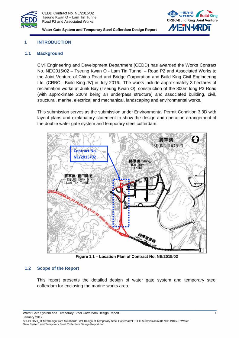
Civil Engineering and Development Department (CEDD) has awarded the Works Contract
No. NE/2015/02 – Tseung Kwan O - Lam Tin Tunnel – Road P2 and Associated Works to
the Joint Venture of China Road and Bridge Corporation and Build King Civil Engineering
Ltd. (CRBC - Build King JV) in July 2016. The works include approximately 3 hectares of
reclamation works at Junk Bay (Tseung Kwan O), construction of the 800m long P2 Road
(with approximate 200m being an underpass structure) and associated building, civil,
structural, marine, electrical and mechanical, landscaping and environmental works.
This submission serves as the submission under Environmental Permit Condition 3.3D with
layout plans and explanatory statement to show the design and operation arrangement of
the double water gate system and temporary steel cofferdam.
Figure 1.1 – Location Plan of Contract No. NE/2015/02
1.2 Scope of the Report
This report presents the detailed design of water gate system and temporary steel
cofferdam for enclosing the marine works area.
Contract No.
NE/2015/02
CEDD Contract No. NE/2015/02 Tseung Kwan O – Lam Tin Tunnel Road P2 and Associated Works Water Gate System and Temporary Steel Cofferdam Design Report
Water Gate System and Temporary Steel Cofferdam Design Report 2
January 2017 S:\UPLOAD_TEMP\Design from Meinhardt\TW1 Design of Temporary Steel Cofferdam\ET IEC Submissions\20170114\Rev. E\Water Gate System and Temporary Steel Cofferdam Design Report.doc
2 DESIGN OF WATER GATE SYSTEM
2.1 Description of Water Gate System
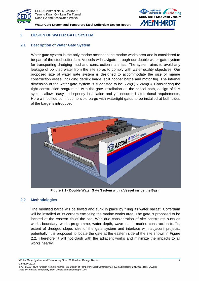
Water gate system is the only marine access to the marine works area and is considered to
be part of the steel cofferdam. Vessels will navigate through our double water gate system
for transporting dredging mud and construction materials. The system aims to avoid any
leakage of polluted water from the site so as to comply with water quality objectives. Our
proposed size of water gate system is designed to accommodate the size of marine
construction vessel including derrick barge, split hopper barge and motor tug. The internal
dimension of the water gate system is suggested to be 55m(L) x 24m(B). Considering the
tight construction programme with the gate installation on the critical path, design of this
system allows easy and speedy installation and yet ensures its functional requirements.
Here a modified semi-submersible barge with watertight gates to be installed at both sides
of the barge is introduced.
Figure 2.1 - Double Water Gate System with a Vessel inside the Basin
2.2 Methodologies
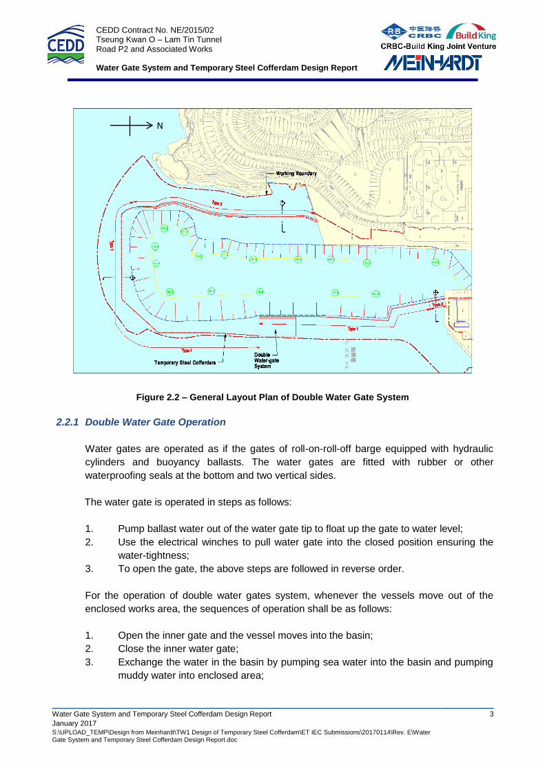
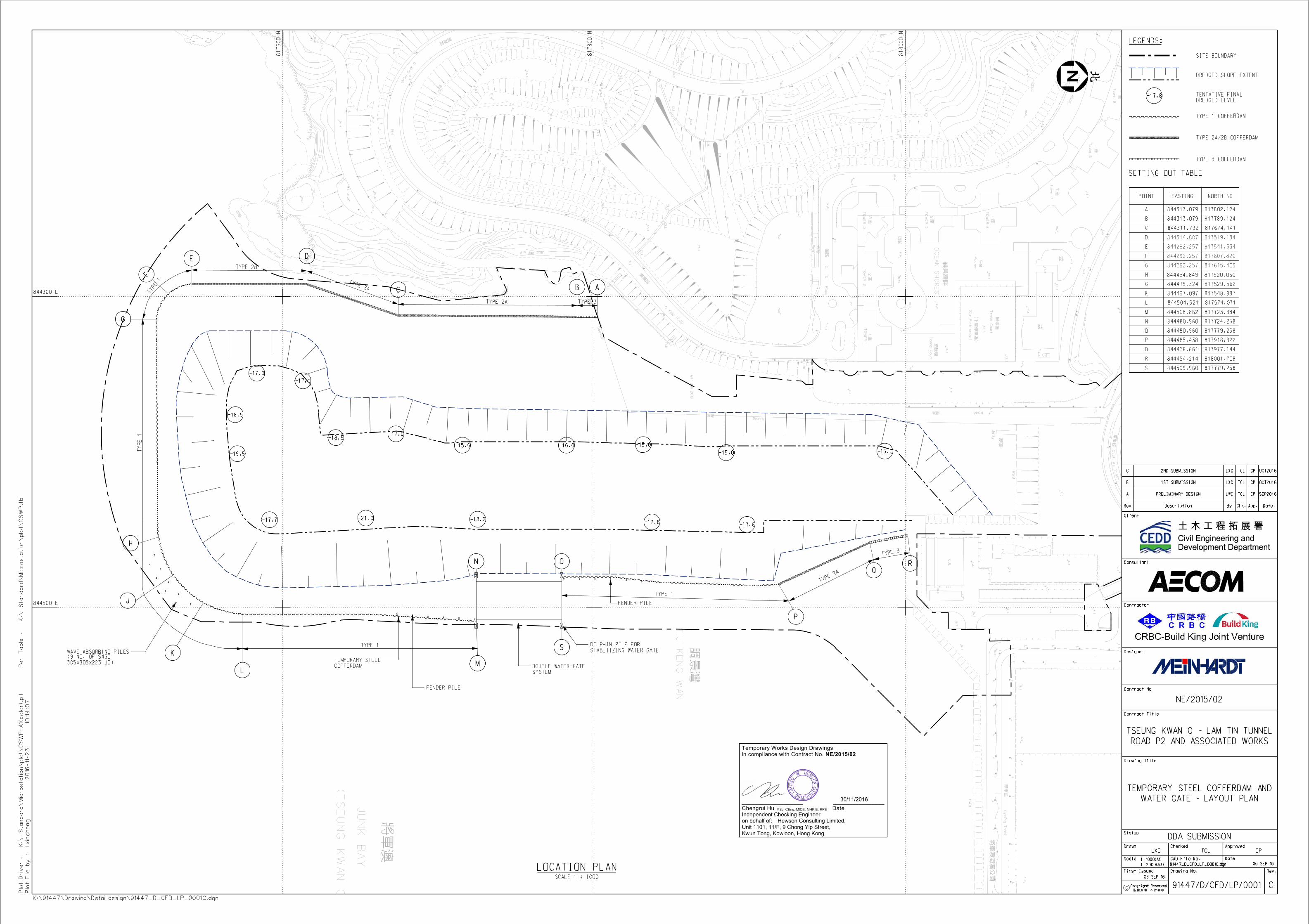
The modified barge will be towed and sunk in place by filling its water ballast. Cofferdam
will be installed at its corners enclosing the marine works area. The gate is proposed to be
located at the eastern tip of the site. With due consideration of site constraints such as
works boundary, works programme, water depth, wave loads, marine construction traffic,
extent of dredged slope, size of the gate system and interface with adjacent projects,
potentially, it is proposed to locate the gate at the eastern side of the site shown in Figure
2.2. Therefore, it will not clash with the adjacent works and minimize the impacts to all
works nearby.
CEDD Contract No. NE/2015/02 Tseung Kwan O – Lam Tin Tunnel Road P2 and Associated Works Water Gate System and Temporary Steel Cofferdam Design Report
Water Gate System and Temporary Steel Cofferdam Design Report 3
January 2017 S:\UPLOAD_TEMP\Design from Meinhardt\TW1 Design of Temporary Steel Cofferdam\ET IEC Submissions\20170114\Rev. E\Water Gate System and Temporary Steel Cofferdam Design Report.doc
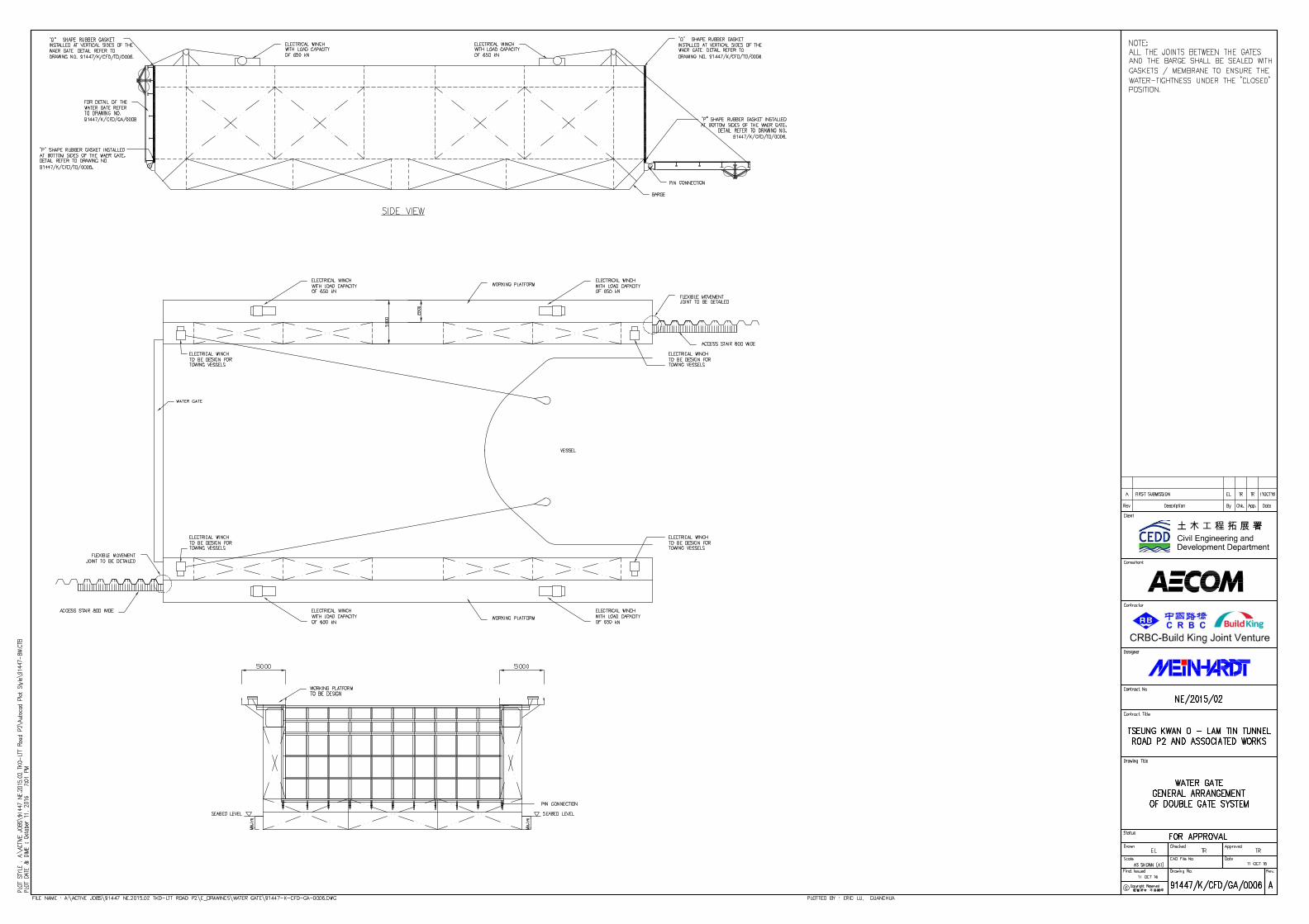
Figure 2.2 – General Layout Plan of Double Water Gate System
2.2.1 Double Water Gate Operation
Water gates are operated as if the gates of roll-on-roll-off barge equipped with hydraulic
cylinders and buoyancy ballasts. The water gates are fitted with rubber or other
waterproofing seals at the bottom and two vertical sides.
The water gate is operated in steps as follows:
1. Pump ballast water out of the water gate tip to float up the gate to water level;
2. Use the electrical winches to pull water gate into the closed position ensuring the
water-tightness;
3. To open the gate, the above steps are followed in reverse order.
For the operation of double water gates system, whenever the vessels move out of the
enclosed works area, the sequences of operation shall be as follows:
1. Open the inner gate and the vessel moves into the basin;
2. Close the inner water gate;
3. Exchange the water in the basin by pumping sea water into the basin and pumping
muddy water into enclosed area;
N
CEDD Contract No. NE/2015/02 Tseung Kwan O – Lam Tin Tunnel Road P2 and Associated Works Water Gate System and Temporary Steel Cofferdam Design Report
Water Gate System and Temporary Steel Cofferdam Design Report 4
January 2017 S:\UPLOAD_TEMP\Design from Meinhardt\TW1 Design of Temporary Steel Cofferdam\ET IEC Submissions\20170114\Rev. E\Water Gate System and Temporary Steel Cofferdam Design Report.doc
11
22
33
44
55
66
VV
22
VV
11
VV
22
VV
22
VV
22
VV
22
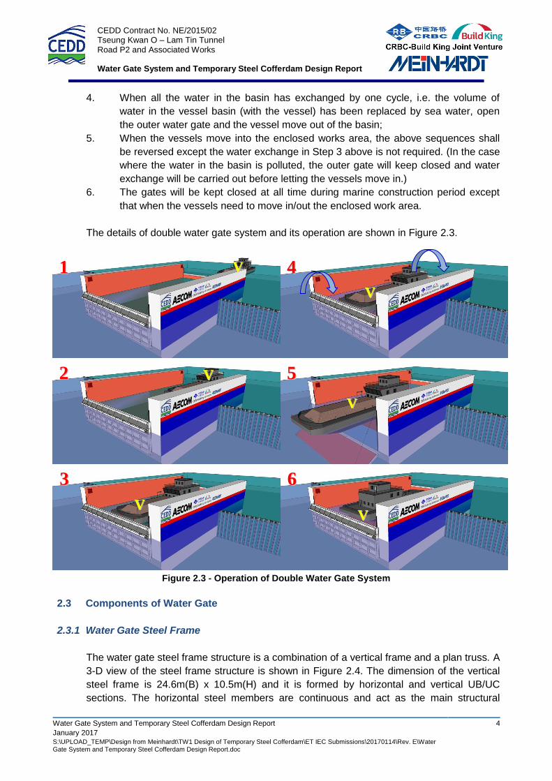
4. When all the water in the basin has exchanged by one cycle, i.e. the volume of
water in the vessel basin (with the vessel) has been replaced by sea water, open
the outer water gate and the vessel move out of the basin;
5. When the vessels move into the enclosed works area, the above sequences shall
be reversed except the water exchange in Step 3 above is not required. (In the case
where the water in the basin is polluted, the outer gate will keep closed and water
exchange will be carried out before letting the vessels move in.)
6. The gates will be kept closed at all time during marine construction period except
that when the vessels need to move in/out the enclosed work area.
The details of double water gate system and its operation are shown in Figure 2.3.
Figure 2.3 - Operation of Double Water Gate System
2.3 Components of Water Gate
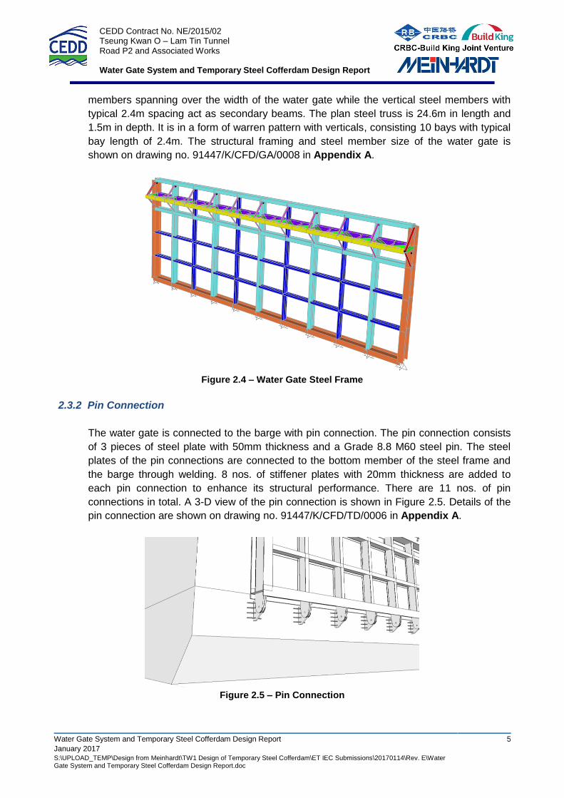
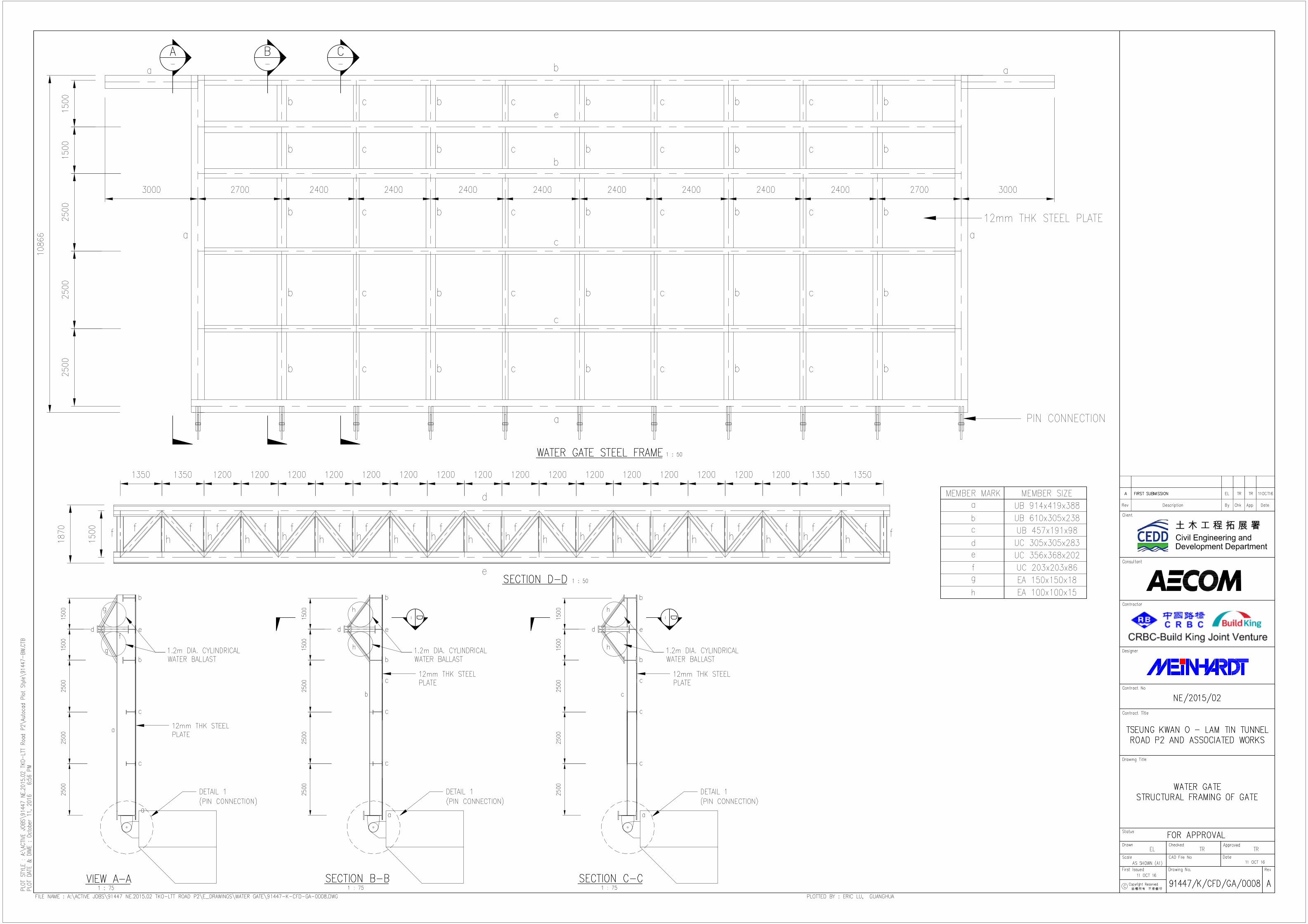
2.3.1 Water Gate Steel Frame
The water gate steel frame structure is a combination of a vertical frame and a plan truss. A
3-D view of the steel frame structure is shown in Figure 2.4. The dimension of the vertical
steel frame is 24.6m(B) x 10.5m(H) and it is formed by horizontal and vertical UB/UC
sections. The horizontal steel members are continuous and act as the main structural
CEDD Contract No. NE/2015/02 Tseung Kwan O – Lam Tin Tunnel Road P2 and Associated Works Water Gate System and Temporary Steel Cofferdam Design Report
Water Gate System and Temporary Steel Cofferdam Design Report 5
January 2017 S:\UPLOAD_TEMP\Design from Meinhardt\TW1 Design of Temporary Steel Cofferdam\ET IEC Submissions\20170114\Rev. E\Water Gate System and Temporary Steel Cofferdam Design Report.doc
members spanning over the width of the water gate while the vertical steel members with
typical 2.4m spacing act as secondary beams. The plan steel truss is 24.6m in length and
1.5m in depth. It is in a form of warren pattern with verticals, consisting 10 bays with typical
bay length of 2.4m. The structural framing and steel member size of the water gate is
shown on drawing no. 91447/K/CFD/GA/0008 in Appendix A.
Figure 2.4 – Water Gate Steel Frame
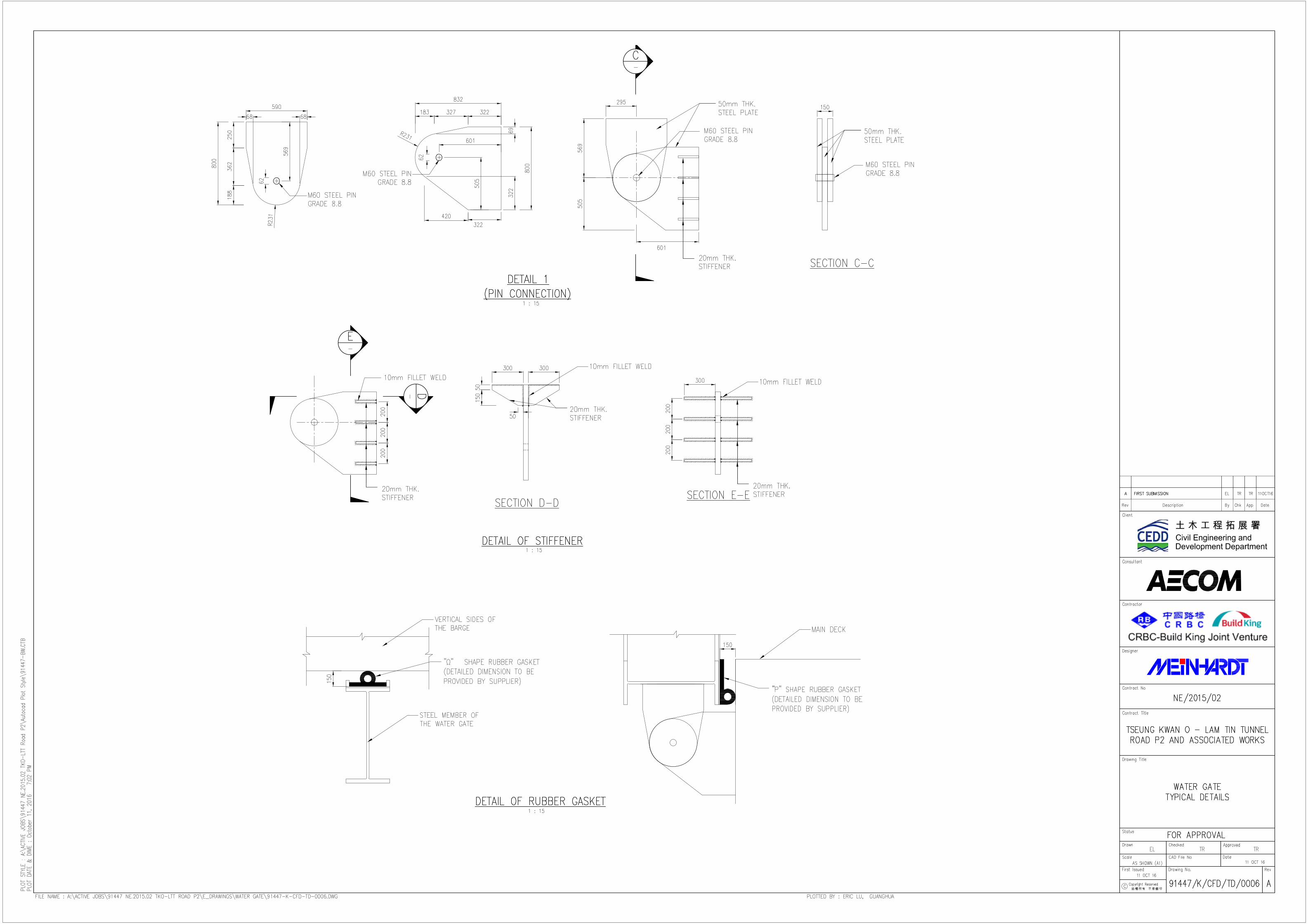
2.3.2 Pin Connection
The water gate is connected to the barge with pin connection. The pin connection consists
of 3 pieces of steel plate with 50mm thickness and a Grade 8.8 M60 steel pin. The steel
plates of the pin connections are connected to the bottom member of the steel frame and
the barge through welding. 8 nos. of stiffener plates with 20mm thickness are added to
each pin connection to enhance its structural performance. There are 11 nos. of pin
connections in total. A 3-D view of the pin connection is shown in Figure 2.5. Details of the
pin connection are shown on drawing no. 91447/K/CFD/TD/0006 in Appendix A.
Figure 2.5 – Pin Connection
CEDD Contract No. NE/2015/02 Tseung Kwan O – Lam Tin Tunnel Road P2 and Associated Works Water Gate System and Temporary Steel Cofferdam Design Report
Water Gate System and Temporary Steel Cofferdam Design Report 6
January 2017 S:\UPLOAD_TEMP\Design from Meinhardt\TW1 Design of Temporary Steel Cofferdam\ET IEC Submissions\20170114\Rev. E\Water Gate System and Temporary Steel Cofferdam Design Report.doc
2.4 Demonstration of Calculation
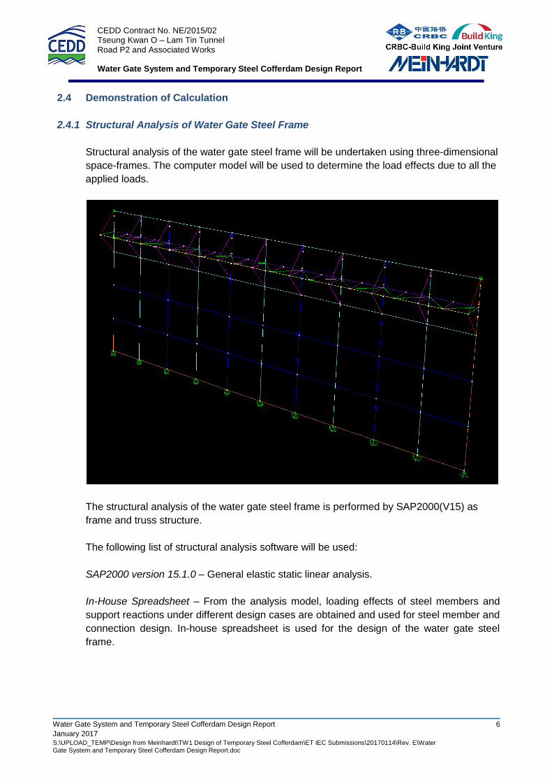
2.4.1 Structural Analysis of Water Gate Steel Frame
Structural analysis of the water gate steel frame will be undertaken using three-dimensional
space-frames. The computer model will be used to determine the load effects due to all the
applied loads.
The structural analysis of the water gate steel frame is performed by SAP2000(V15) as
frame and truss structure.
The following list of structural analysis software will be used:
SAP2000 version 15.1.0 – General elastic static linear analysis.
In-House Spreadsheet – From the analysis model, loading effects of steel members and
support reactions under different design cases are obtained and used for steel member and
connection design. In-house spreadsheet is used for the design of the water gate steel
frame.
CEDD Contract No. NE/2015/02 Tseung Kwan O – Lam Tin Tunnel Road P2 and Associated Works Water Gate System and Temporary Steel Cofferdam Design Report
Water Gate System and Temporary Steel Cofferdam Design Report 7
January 2017 S:\UPLOAD_TEMP\Design from Meinhardt\TW1 Design of Temporary Steel Cofferdam\ET IEC Submissions\20170114\Rev. E\Water Gate System and Temporary Steel Cofferdam Design Report.doc
3 DESIGN OF TEMPORARY STEEL COFFERDAM
3.1 Available Geotechnical Information
3.1.1 Site Geology
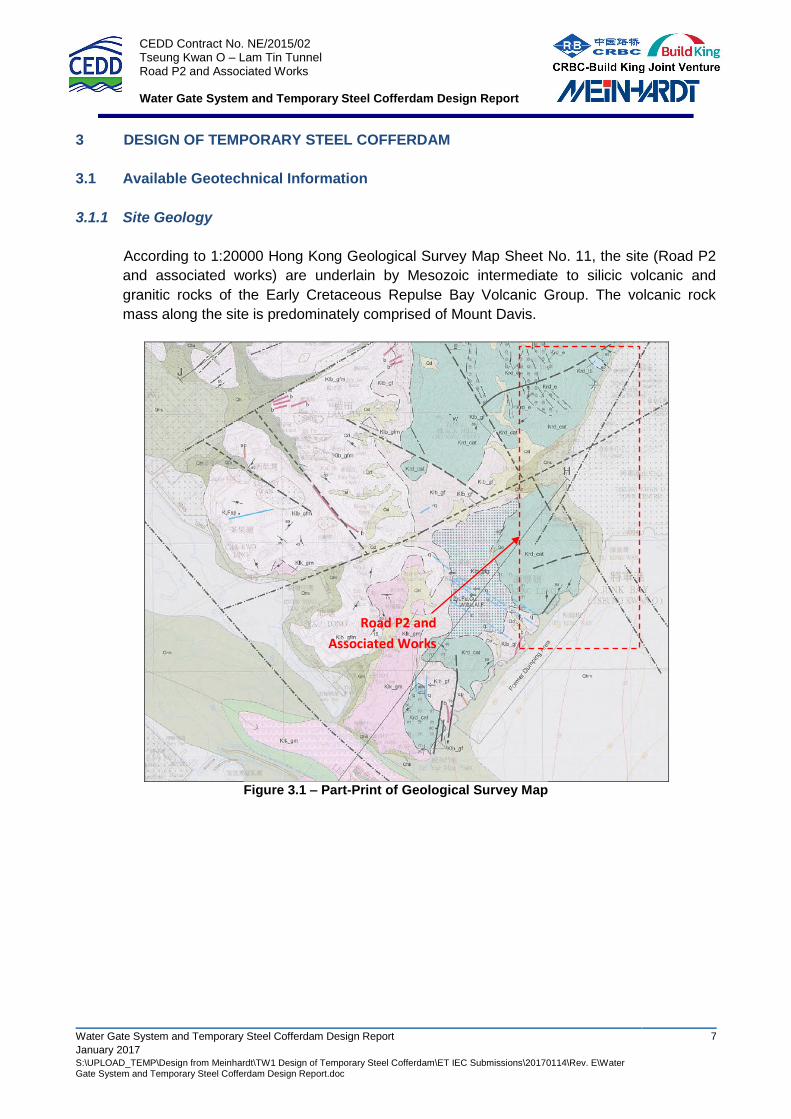
According to 1:20000 Hong Kong Geological Survey Map Sheet No. 11, the site (Road P2
and associated works) are underlain by Mesozoic intermediate to silicic volcanic and
granitic rocks of the Early Cretaceous Repulse Bay Volcanic Group. The volcanic rock
mass along the site is predominately comprised of Mount Davis.
Figure 3.1 – Part-Print of Geological Survey Map
Road P2 and
Associated Works
CEDD Contract No. NE/2015/02 Tseung Kwan O – Lam Tin Tunnel Road P2 and Associated Works Water Gate System and Temporary Steel Cofferdam Design Report
Water Gate System and Temporary Steel Cofferdam Design Report 8
January 2017 S:\UPLOAD_TEMP\Design from Meinhardt\TW1 Design of Temporary Steel Cofferdam\ET IEC Submissions\20170114\Rev. E\Water Gate System and Temporary Steel Cofferdam Design Report.doc
3.2 Geotechnical Design Parameters
3.2.1 Adopted Soil Parameters
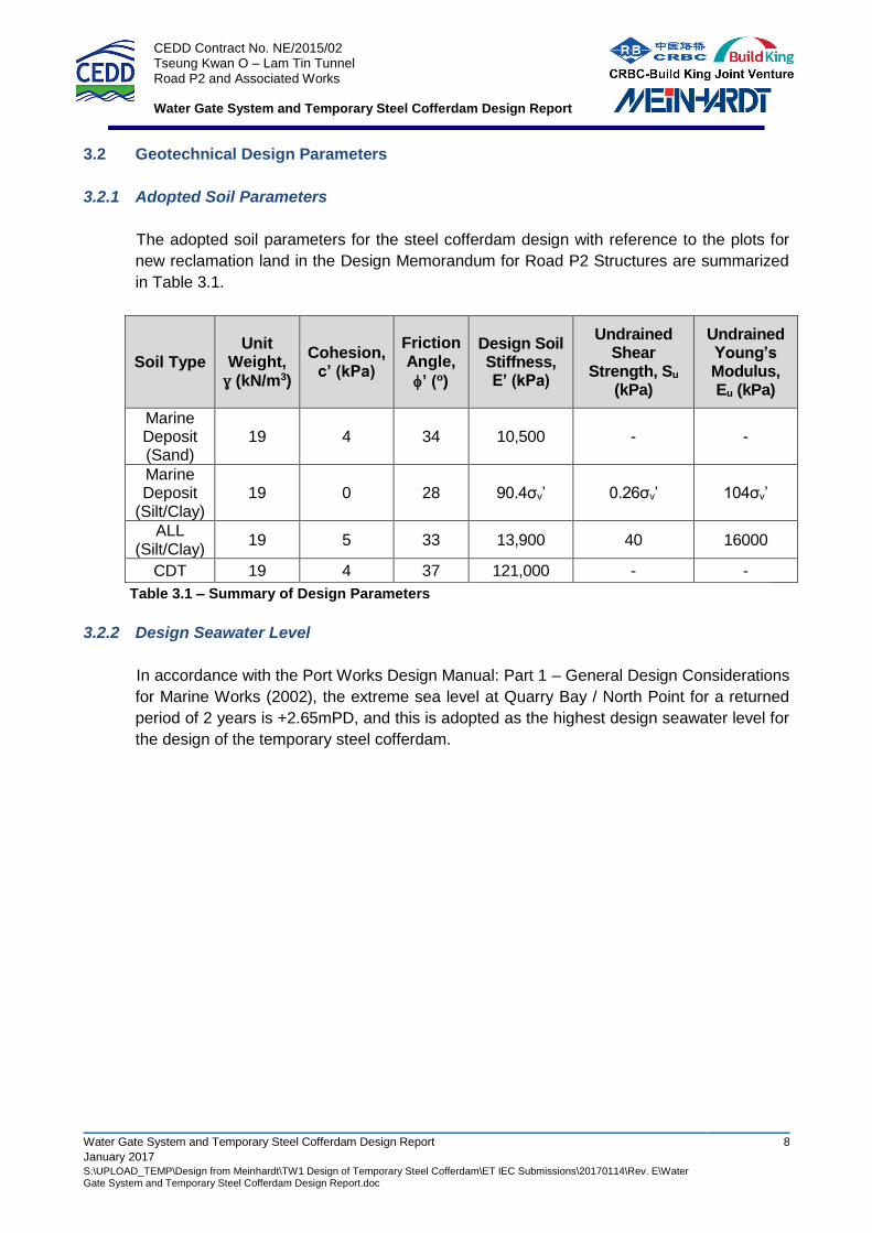
The adopted soil parameters for the steel cofferdam design with reference to the plots for
new reclamation land in the Design Memorandum for Road P2 Structures are summarized
in Table 3.1.
Soil Type Unit
Weight, ɣ (kN/m3)
Cohesion, c’ (kPa)
Friction Angle,
’ (o)
Design Soil Stiffness, E’ (kPa)
Undrained Shear
Strength, Su (kPa)
Undrained Young’s Modulus, Eu (kPa)
Marine Deposit (Sand)
19 4 34 10,500 - -
Marine Deposit
(Silt/Clay) 19 0 28 90.4σv’ 0.26σv’ 104σv’
ALL (Silt/Clay)
19 5 33 13,900 40 16000
CDT 19 4 37 121,000 - -
Table 3.1 – Summary of Design Parameters
3.2.2 Design Seawater Level
In accordance with the Port Works Design Manual: Part 1 – General Design Considerations
for Marine Works (2002), the extreme sea level at Quarry Bay / North Point for a returned
period of 2 years is +2.65mPD, and this is adopted as the highest design seawater level for
the design of the temporary steel cofferdam.
CEDD Contract No. NE/2015/02 Tseung Kwan O – Lam Tin Tunnel Road P2 and Associated Works Water Gate System and Temporary Steel Cofferdam Design Report
Water Gate System and Temporary Steel Cofferdam Design Report 9
January 2017 S:\UPLOAD_TEMP\Design from Meinhardt\TW1 Design of Temporary Steel Cofferdam\ET IEC Submissions\20170114\Rev. E\Water Gate System and Temporary Steel Cofferdam Design Report.doc
3.3 Proposed Temporary Steel Cofferdam
3.3.1 General
The actual dredging level and area will depend on the cone penetration test results and the
design of dredging slope. In addition, sufficient working space has to be provided. By
considering the above, the area enclosed by the steel cofferdam has been reviewed and
updated as shown in the latest steel cofferdam design drawings. Notwithstanding this, the
total maximum dredged volume (400,000m3) will be strictly followed.
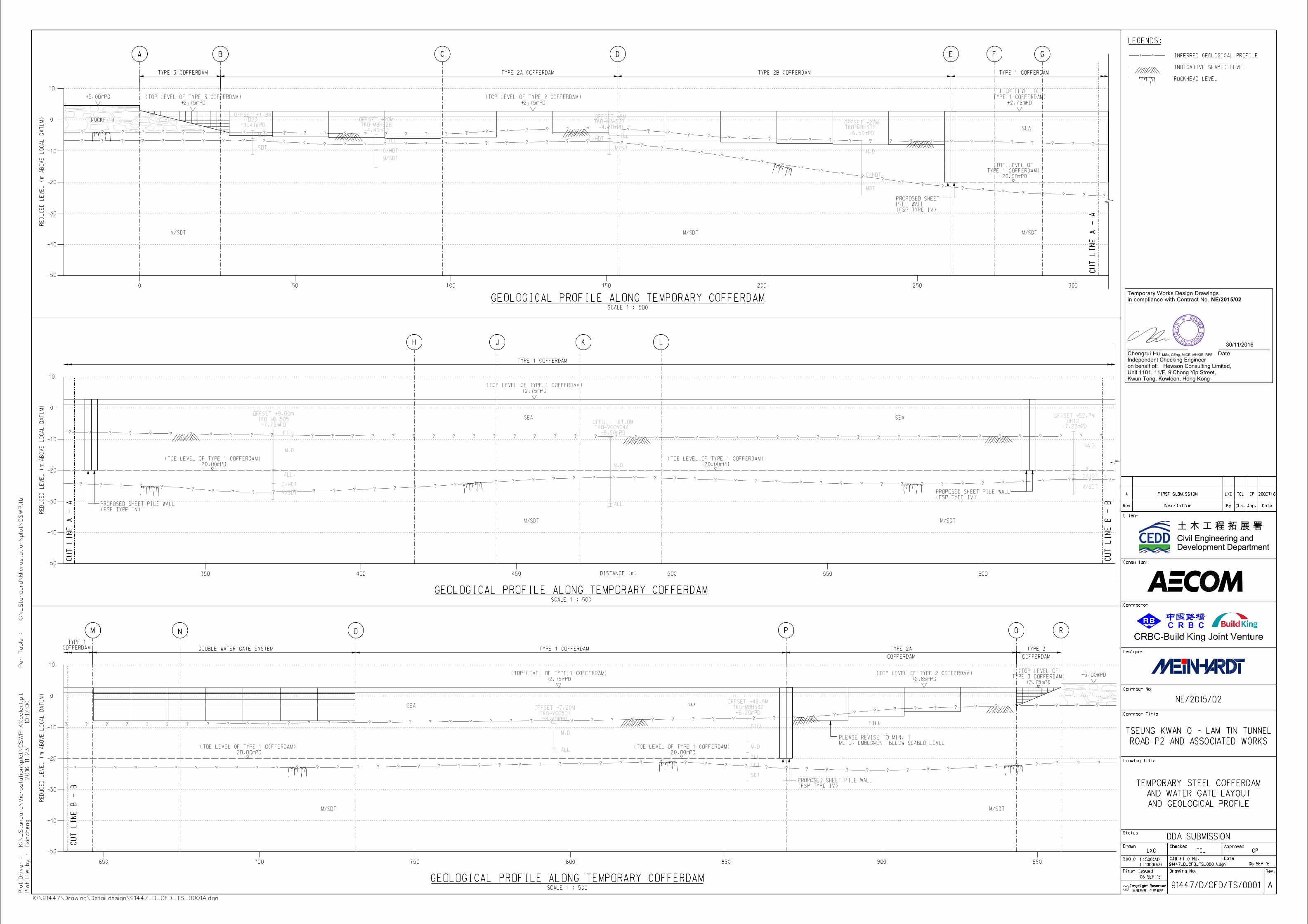
3 types of temporary steel cofferdam, namely Type 1, Type 2 and Type 3, are proposed
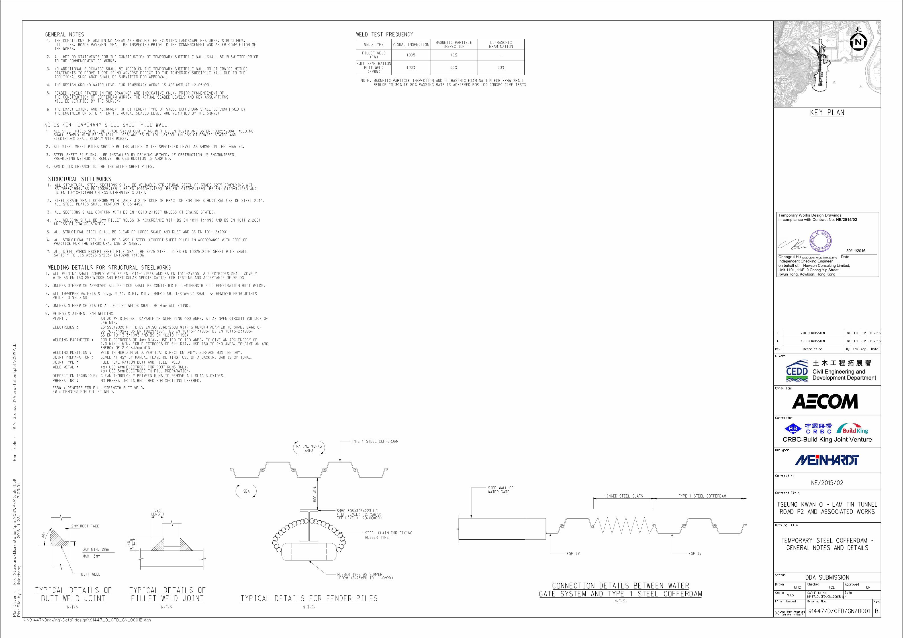
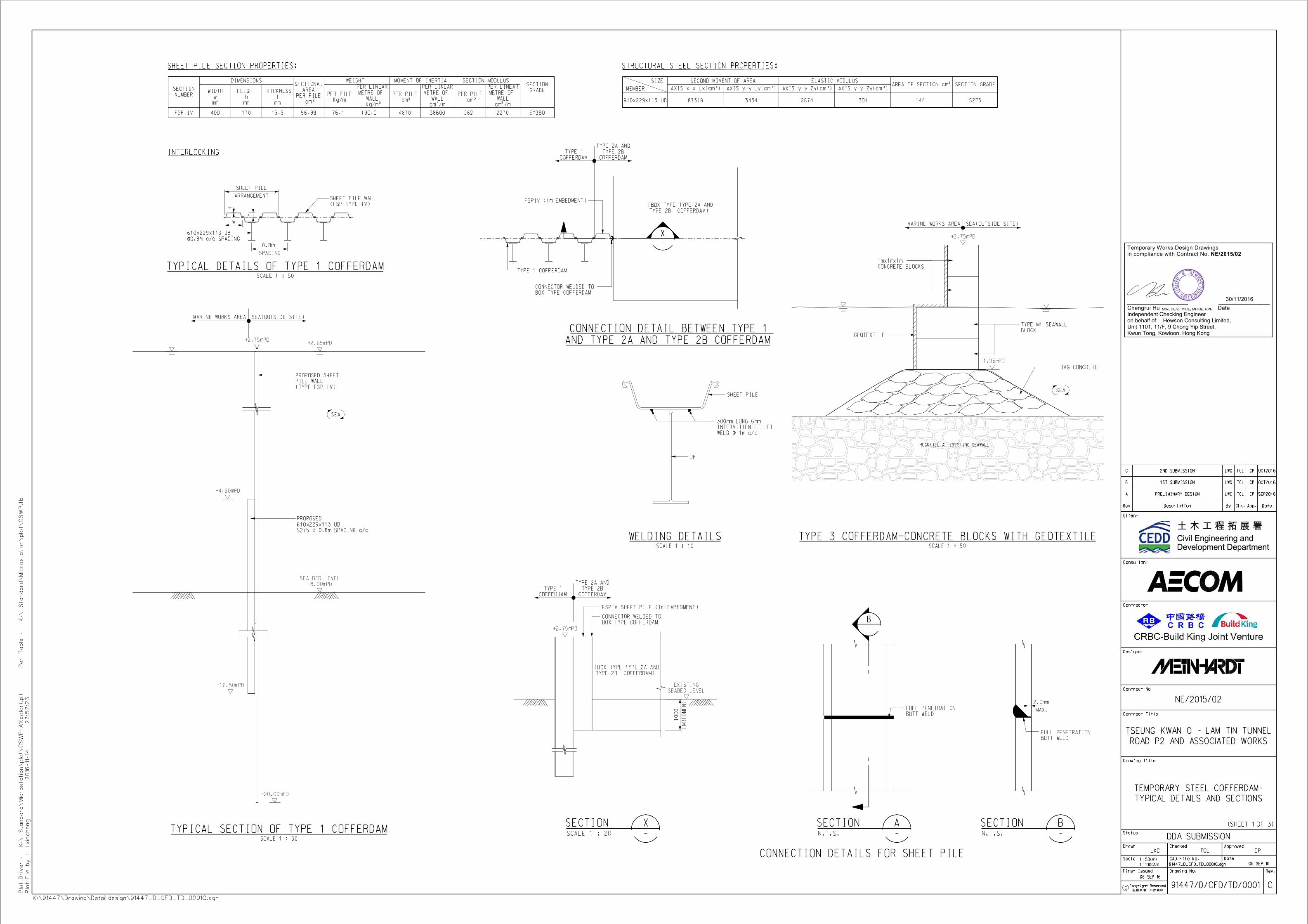
with consideration of the site conditions. Type 1 steel cofferdam is composed of composite
interlocked steel sheet pile wall (FSP IV) locally strengthened with universal beams
(610x229x113kg/m UB) at 800mm c/c. Type 2 cofferdam is in the form of pre-fabricated
steel tanks. Type 3 is formed of concrete block wall and geotextile.
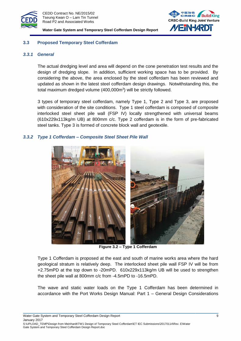
3.3.2 Type 1 Cofferdam – Composite Steel Sheet Pile Wall
Figure 3.2 – Type 1 Cofferdam
Type 1 Cofferdam is proposed at the east and south of marine works area where the hard
geological stratum is relatively deep. The interlocked sheet pile wall FSP IV will be from
+2.75mPD at the top down to -20mPD. 610x229x113kg/m UB will be used to strengthen
the sheet pile wall at 800mm c/c from -4.5mPD to -16.5mPD.
The wave and static water loads on the Type 1 Cofferdam has been determined in
accordance with the Port Works Design Manual: Part 1 – General Design Considerations
CEDD Contract No. NE/2015/02 Tseung Kwan O – Lam Tin Tunnel Road P2 and Associated Works Water Gate System and Temporary Steel Cofferdam Design Report
Water Gate System and Temporary Steel Cofferdam Design Report 10
January 2017 S:\UPLOAD_TEMP\Design from Meinhardt\TW1 Design of Temporary Steel Cofferdam\ET IEC Submissions\20170114\Rev. E\Water Gate System and Temporary Steel Cofferdam Design Report.doc
for Marine Works. Stability checking, as well as detailed analysis of the Type 1 Cofferdam
using the Geotechnical Programme “PLAXIS”, is performed.
The structural checking of the Type 1 Cofferdam is based on the maximum bending
moment and shear force obtained from the PLAXIS analysis. The structural checking is
carried out in accordance with the Code of Practice for Structural Use of Steel 2011.
The detailed design drawings are enclosed in Appendix A.
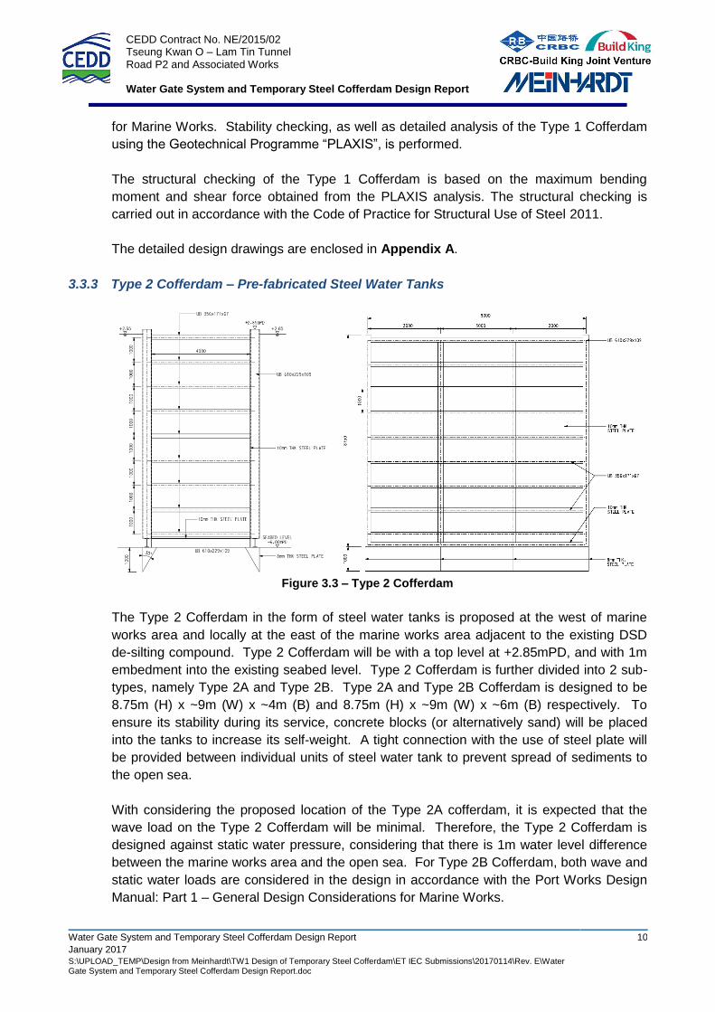
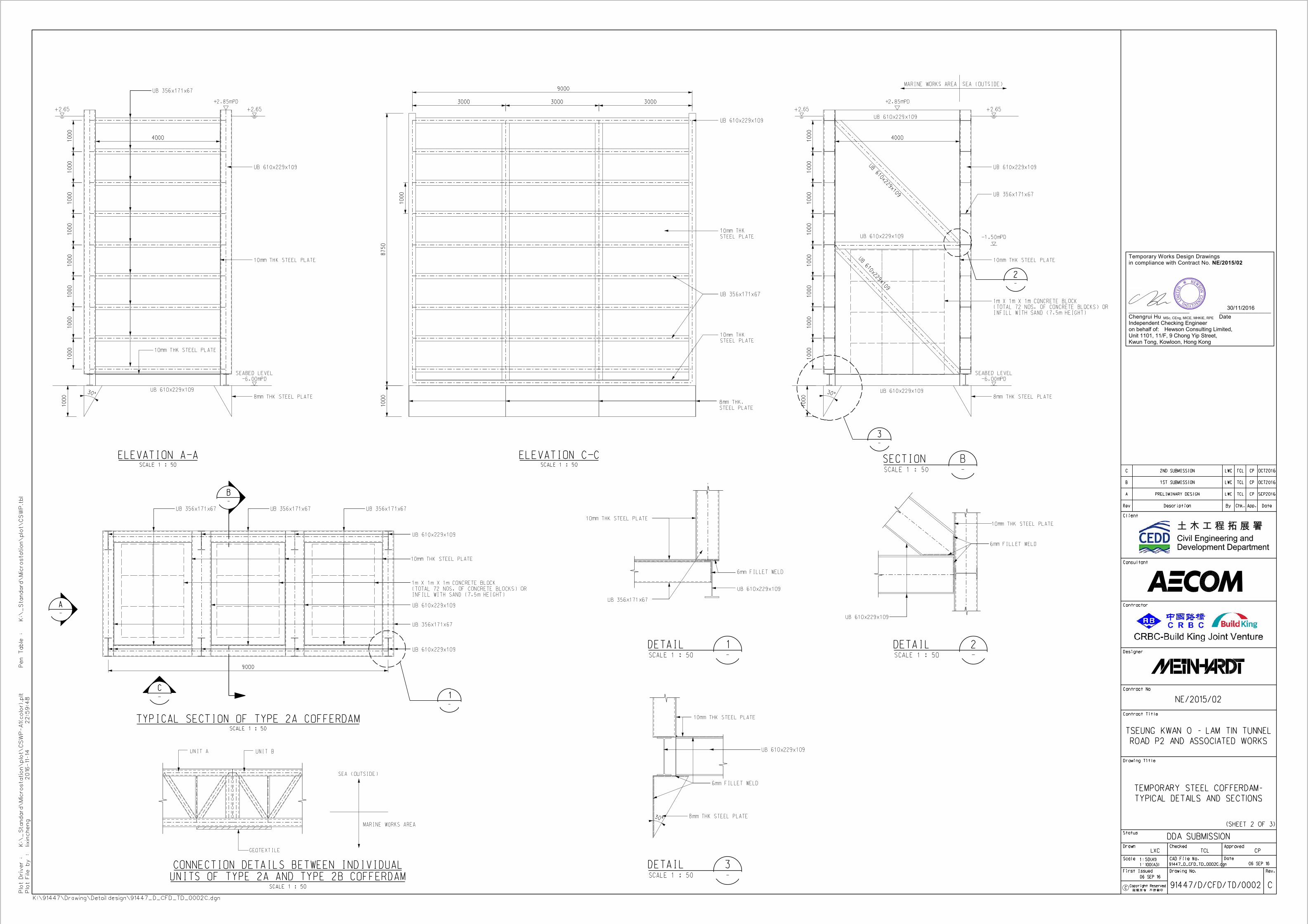
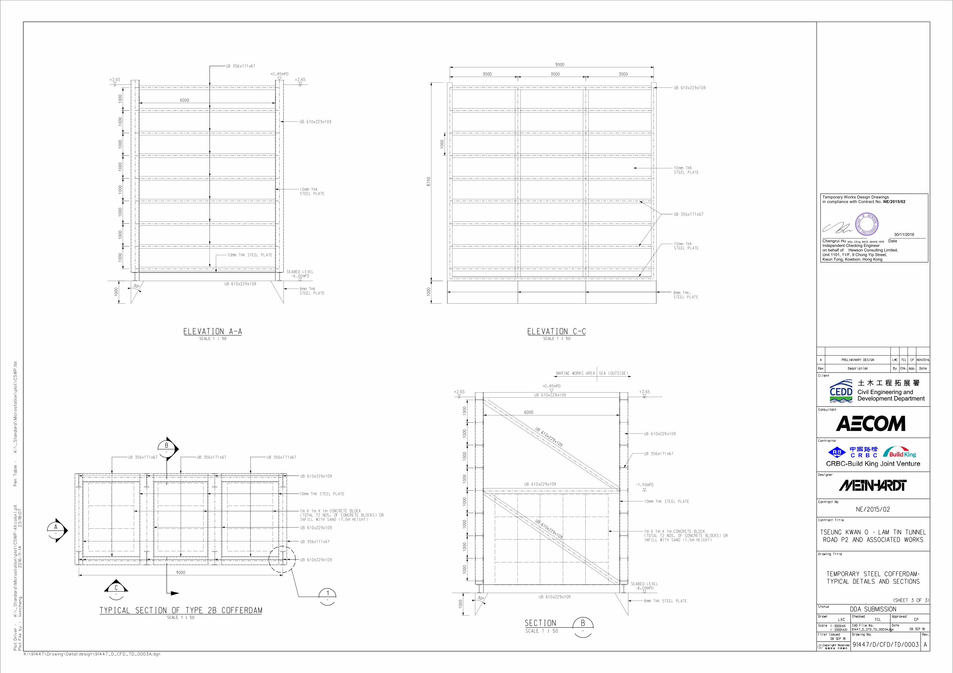
3.3.3 Type 2 Cofferdam – Pre-fabricated Steel Water Tanks
Figure 3.3 – Type 2 Cofferdam
The Type 2 Cofferdam in the form of steel water tanks is proposed at the west of marine
works area and locally at the east of the marine works area adjacent to the existing DSD
de-silting compound. Type 2 Cofferdam will be with a top level at +2.85mPD, and with 1m
embedment into the existing seabed level. Type 2 Cofferdam is further divided into 2 sub-
types, namely Type 2A and Type 2B. Type 2A and Type 2B Cofferdam is designed to be
8.75m (H) x ~9m (W) x ~4m (B) and 8.75m (H) x ~9m (W) x ~6m (B) respectively. To
ensure its stability during its service, concrete blocks (or alternatively sand) will be placed
into the tanks to increase its self-weight. A tight connection with the use of steel plate will
be provided between individual units of steel water tank to prevent spread of sediments to
the open sea.
With considering the proposed location of the Type 2A cofferdam, it is expected that the
wave load on the Type 2 Cofferdam will be minimal. Therefore, the Type 2 Cofferdam is
designed against static water pressure, considering that there is 1m water level difference
between the marine works area and the open sea. For Type 2B Cofferdam, both wave and
static water loads are considered in the design in accordance with the Port Works Design
Manual: Part 1 – General Design Considerations for Marine Works.
CEDD Contract No. NE/2015/02 Tseung Kwan O – Lam Tin Tunnel Road P2 and Associated Works Water Gate System and Temporary Steel Cofferdam Design Report
Water Gate System and Temporary Steel Cofferdam Design Report 11
January 2017 S:\UPLOAD_TEMP\Design from Meinhardt\TW1 Design of Temporary Steel Cofferdam\ET IEC Submissions\20170114\Rev. E\Water Gate System and Temporary Steel Cofferdam Design Report.doc
Stability checking, as well as detailed analysis of the Type 2 Cofferdam using the Structural
Programme “SAP2000”, is performed. The structural checking is also carried out in
accordance with the Code of Practice for Structural Use of Steel 2011.
The detailed design drawings are enclosed in Appendix A.
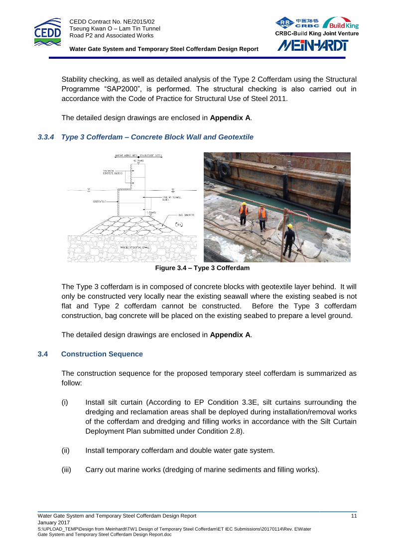
3.3.4 Type 3 Cofferdam – Concrete Block Wall and Geotextile
Figure 3.4 – Type 3 Cofferdam
The Type 3 cofferdam is in composed of concrete blocks with geotextile layer behind. It will
only be constructed very locally near the existing seawall where the existing seabed is not
flat and Type 2 cofferdam cannot be constructed. Before the Type 3 cofferdam
construction, bag concrete will be placed on the existing seabed to prepare a level ground.
The detailed design drawings are enclosed in Appendix A.
3.4 Construction Sequence
The construction sequence for the proposed temporary steel cofferdam is summarized as
follow:
(i) Install silt curtain (According to EP Condition 3.3E, silt curtains surrounding the
dredging and reclamation areas shall be deployed during installation/removal works
of the cofferdam and dredging and filling works in accordance with the Silt Curtain
Deployment Plan submitted under Condition 2.8).
(ii) Install temporary cofferdam and double water gate system.
(iii) Carry out marine works (dredging of marine sediments and filling works).
CEDD Contract No. NE/2015/02 Tseung Kwan O – Lam Tin Tunnel Road P2 and Associated Works Water Gate System and Temporary Steel Cofferdam Design Report
Water Gate System and Temporary Steel Cofferdam Design Report 12
January 2017 S:\UPLOAD_TEMP\Design from Meinhardt\TW1 Design of Temporary Steel Cofferdam\ET IEC Submissions\20170114\Rev. E\Water Gate System and Temporary Steel Cofferdam Design Report.doc
4 CONCLUSION
Based on the detailed analysis and design of the water gate system and temporary steel
cofferdam, it is considered that the proposed scheme is feasible and safe with adequate
factor of safety, and the impacts of the proposed works on the adjacent ground,
underground utilities and existing structures are considered negligible.
This report has also demonstrated that the marine water quality outside the cofferdam will
not be adversely affected by the dredging/filling works, and the design is fully compliant to
EP Condition 3.3D.
CEDD Contract No. NE/2015/02 Tseung Kwan O – Lam Tin Tunnel Road P2 and Associated Works Water Gate System and Temporary Steel Cofferdam Design Report
Water Gate System and Temporary Steel Cofferdam Design Report
January 2017 S:\UPLOAD_TEMP\Design from Meinhardt\TW1 Design of Temporary Steel Cofferdam\ET IEC Submissions\20170114\Rev. E\Water Gate System and Temporary Steel Cofferdam Design Report.doc
APPENDIX A
DRAWINGS
Temporary Works Design Drawings in compliance with Contract No. NE/2015/02
___________________ ________________ Chengrui Hu Date Independent Checking Engineer on behalf of: Hewson Consulting Limited, Unit 1101, 11/F, 9 Chong Yip Street, Kwun Tong, Kowloon, Hong Kong
30/11/2016
MSc, CEng, MICE, MHKIE, RPE