Embed Size (px)
Citation preview
Contract no. A832-059
Development of Species Profiles for Selected Organic Emission Sources
April 30, 1991
California Polytechnic State University
Prepared for California Air Resources Board
Albert C. Censullo, Ph. D.
Final Report
on
Development ofSpecies Profiles for Selected Organic Emission Sources
Volume II: Engine Exhaust Emissions
Prepared by
Albert C. Censullo, Ph.D. Chemistry Department
California Polytechnic State University
ABSTRACT
This project involved the characterization of fugitive emissions from three source categories. Category 1 sources comprised emissions from California oil production facilities. Site selection criteria were developed, and resulted in the generation of a prioritized list of locations where emissions from light, medium and heavy crude petroleum operations would be sampled. At each site, samples from wellhead, pipeline, processing and storage systems were obtained. Specific components for sampling were pre-screened for positive hydrocarbon emissions using a portable hydrocarbon analyzer. The sampling methodology involved collection of 38 samples in evacuated stainless steel canisters. Detailed emission species profiles were determined by gas chromatography, with flame ionization detection. Peak identification was based on retention times, as well as separate gas chromatographic runs using a mass selective detector.
Category 2 and 3 sources included exhaust from utility and heavy-duty engines. The selection of 21 samples, based on estimates of engine populations in California, was described. The design and fabrication of a portable exhaust dilution system was discussed. Diluted exhaust from selected engines was sampled simultaneously for hydrocarbons and aldehydes. Diesel engines were additionally sampled for higher hydrocarbons. Hydrocarbon species were collected into evacuated stainless steel canisters. Aldehydes were absorbed into midget impingers containing DNPH/acetonilrile. High molecular weight hydrocarbons from Diesel exhaust were adsorbed in sorbent tubes filled with XAD-2 resin. Hydrocarbons were speciated by gas chromatographic techniques, as with Category 1 sources. Analysis of DNPH-aldehyde derivatives was performed using high performance liquid chromatography. Extracts from the XAD-2 resin were analyzed by gas chromatography, using a mass selective detector.
iii
DISCLAIMER
The statements and conclusions in this repon are those of the contractor and not necessarily
those of the California Air Resources Board. The mention of commercial products, their
source or use in connection with material reponed herein is not to be construed as either an
actual or implied endorsement of such products.
iv

Table of Contents
I. Introduction ...................................................................................... 1
II. Category 2 and Category 3 Sources ......................................................... 1
A. Background............................................................................ 1
B. Sample Selection Criteria ............................................................ 1
C. Sampling Methodology ............................................................. 14
1. Sampling Tunnel Design..................................................... 14 2. Sampling for Hydrocarbons in Exhaust ...................................21 3. Sampling for Aldehydes .....................................................21 4. Sampling for High Molecular Weight Hydrocarbons ...................27
D. Quality Assurance ....................................................................27
E. Analytical Methodologies ............................................................27
F. Engine Sampling..................................................................... .30
G. Format for Results ...................................................................32
H. Results ................................................................................ .32
1. Aldehyde Analysis Results ..................................................32
I. Discussion ..............................................................................54
1. Aldehyde Results ............................................................54 2. Hydrocarbon Replicate Samples ............................................58 3 Aldehyde and Ketone Concentrations ......................................58 4. Hydrocarbon Concentrations ...............................................58
III. References Cited ..............................................................................68
V
LIST OF APPENDICES
Appendix A - Hydrocarbon References ................................................................................69
Appendix B - Aldehyde References .......................................................................................71
Appendix C - Photographs of Selected Sampling Setups ....................................................73
Appendix D - Protocol for Sampling Engine Exhaust Emissions ......................................78
Appendix E -Analytical Methodologies ................................................................................79
vi
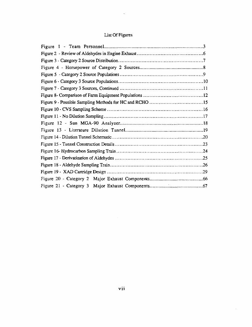
List Of Figures
Figure 1 - Team Personnel. .......................................................................3
Figure 2 - Review of Aldehydes in Engine Exhaust ..........................................6
Figure 3 - Category 2 Source Distribution ......................................................7
Figure 4 - Horsepower of Category 2 Sources.................................................8
Figure 5 - Category 2 Source Populations .....................................................9
Figure 6 - Category 3 Source Populations ...................................................... IO
Figure 7 - Category 3 Sources, Continued ..................................................... 11
Figure 8- Comparison of Farm Equipment Populations ...................................... 12
Figure 9 - Possible Sampling Methods for HC and RCHO .................................. 15
Figure IO - CVS Sampling Scheme ............................................................. 16
Figure 11 - No Dilution Sampling ............................................................... 17
Figure 12 - Sun MGA-90 Analyzer.............................................................. 18
Figure 13 - Literature Dilution Tunnel.. ......................................................... 19
Figure 14 - Dilution Tunnel Schematic ..........................................................20
Figure 15 - Tunnel Construction Details ........................................................23
Figure 16- Hydrocarbon Sampling Train .......................................................24
Figure 17 - Derivatization of Aldehydes ........................................................25
Figure 18 - Aldehyde Sampling Train ...........................................................26
Figure 19 - XAD Cartridge Design .............................................................29
Figure 20 - Category 2 Major Exhaust Components..........................................66
Figure 21 - Category 3 Major Exhaust Components..........................................67
vii
5
10
15
20
25
30
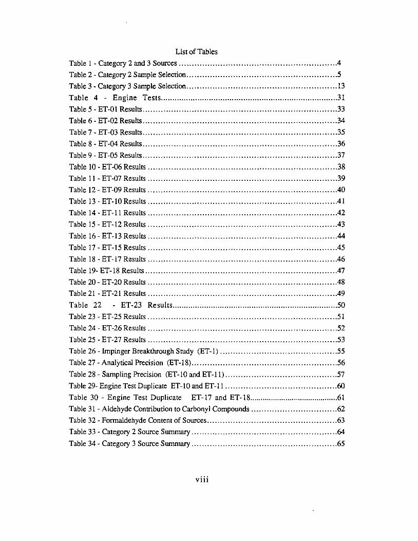
List of Tables
Table 1 - Category 2 and 3 Sources ............................................................ .4
Table 2 - Category 2 Sample Selection ......................................................... .5
Table 3 - Category 3 Sample Selection .......................................................... 13
Table 4 - Engine Tests............................................................................ .31
Table - ET-01 Results ...........................................................................33
Table 6 - ET-02 Results ...........................................................................34
Table 7 - ET-03 Results ...........................................................................35
Table 8 - ET-04 Results ...........................................................................36
Table 9 - ET-05 Results ...........................................................................37
Table - ET-06 Results .........................................................................38
Table 11 - ET-07 Results .........................................................................39
Table 12 - ET-09 Results ........................................................................ .40
Table 13 - ET-10 Results ........................................................................ .41
Table 14 - ET-11 Results ........................................................................ .42
Table - ET-12 Results .........................................................................43
Table 16 - ET-13 Results .........................................................................44
Table 17 - ET-15 Results .........................................................................45
Table i8 - ET-i7 Results ........................................................................ .46
Table 19- ET-18 Results ..........................................................................47
Table - ET-20 Results ........................................................................ .48
Table 21 - ET-21 Results ........................................................................ .49
Table 22 - ET-23 Results............ : ............................................................50
Table 23 - ET-25 Results .........................................................................51
Table 24 - ET-26 Results .........................................................................52
Table - ET-27 Results .........................................................................53
Table 26 - Impinger Breakthrough Study (ET-1) .............................................55
Table 27 - Analytical Precision (ET-18) ........................................................56
Table 28 - Sampling Precision (ET-10 and ET-11) ...........................................57
Table 29- Engine Test Duplicate ET-10 and ET-11 ...........................................60
Table - Engine Test Duplicate ET-17 and ET-18..........................................61
Table 31 - Aldehyde Contribution to Carbonyl Compounds .................................62
Table 32 - Formaldehyde Content of Sources ..................................................63
Table 33 - Category 2 Source Summary ........................................................64
Table 34 - Category 3 Source Summary ........................................................65
Vlll
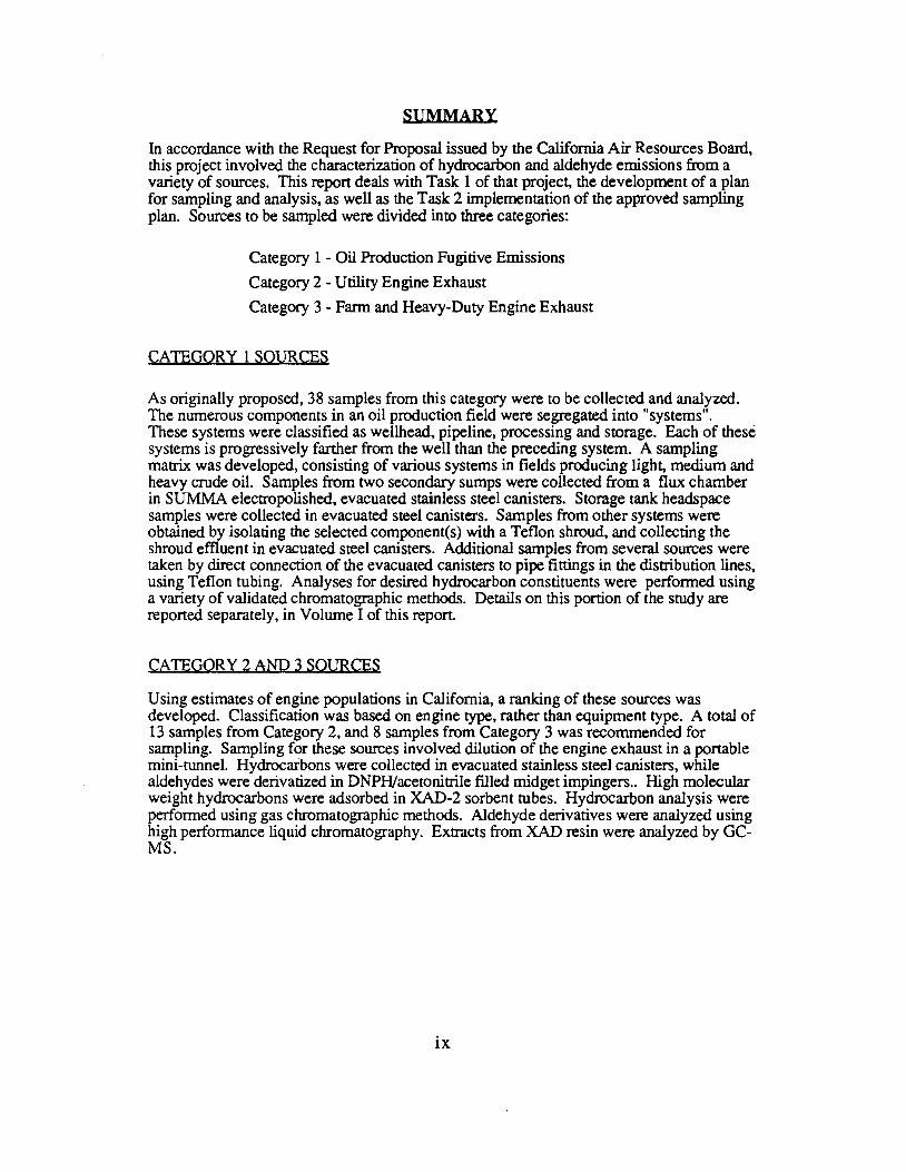
SUMMARY
In accordance with the Request for Proposal issued by the California Air Resources Board, this project involved the characterization of hydrocarbon and aldehyde emissions from a variety of sources. This report deals with Task 1 of that project, the development of a plan for sampling and analysis, as well as the Task 2 implementation of the approved sampling plan. Sources to be sampled were divided into three categories:
Category 1 - Oil Production Fugitive Emissions
Category 2 - Utility Engine Exhaust
Category 3 - Farm and Heavy-Duty Engine Exhaust
CATEGORY 1 SOURCES
As originally proposed, 38 samples from this category were to be collected and analyzed. The numerous components in an oil production field were segregated into "systems". These systems were classified as wellhead, pipeline, processing and storage. Each of these systems is progressively farther from the well than the preceding system. A sampling matrix was developed, consisting of various systems in fields producing light, medium and heavy crude oil. Samples from two secondary sumps were collected from a flux chamber in SUMMA electropolished, evacuated stainless steel canisters. Storage tank headspace samples were collected in evacuated steel canisters. Samples from other systems were obtained by isolating the selected component(s) with a Teflon shroud, and collecting the shroud effluent in evacuated steel canisters. Additional samples from several sources were taken by direct connection of the evacuated canisters to pipe fittings in the distribution lines, using Teflon tubing. Analyses for desired hydrocarbon constituents were performed using a variety of validated chromatographic methods. Details on this portion of the study are reported separately, in Volume I of this repon.
CATEGORY 2AND 3SOURCES
Using estimates of engine populations in California, a ranking of these sources was developed. Classification was based on engine type, rather than equipment type. A total of 13 samples from Category 2, and 8 samples from Category 3 was recommended for sampling. Sampling for these sources involved dilution of the engine exhaust in a portable mini-tunnel. Hydrocarbons were collected in evacuated stainless steel canisters, while aldehydes were derivatized in DNPH/acetonitrile filled midget impingers .. High molecular weight hydrocarbons were adsorbed in XAD-2 sorbent tubes. Hydrocarbon analysis were performed using gas chromatographic methods. Aldehyde derivatives were analyzed using high performance liquid chromatography. Extracts from XAD resin were analyzed by GCMS.
lX
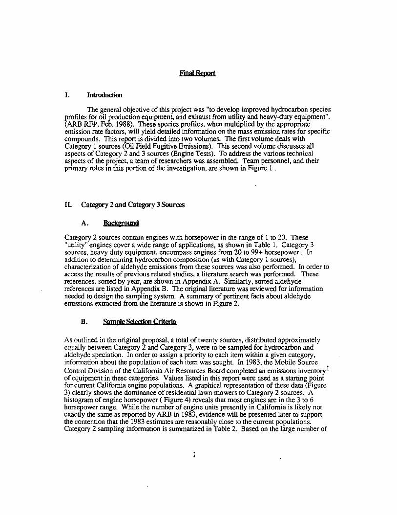
Fjpal Report
I. Introduction
The general objective of this project was "to develop improved hydrocarbon species profiles for oil production equipment, and exhaust from utility and heavy-duty equipment". (ARB RFP, Feb. 1988). These species profiles, when multiplied by the appropriate emission rate factors, will yield detailed information on the mass emission rates for specific compounds. This report is divided into two volumes. The first volume deals with Category 1 sources (Oil Field Fugitive Emissions). This second volume discusses all aspects of Category 2 and 3 sources (Engine Tests). To address the various technical aspects of the project, a team of researchers was assembled. Team personnel, and their primary roles in this portion of the investigation, are shown in Figure 1 .
II. Category 2 and Category 3 Sources
A. BackUQUPd
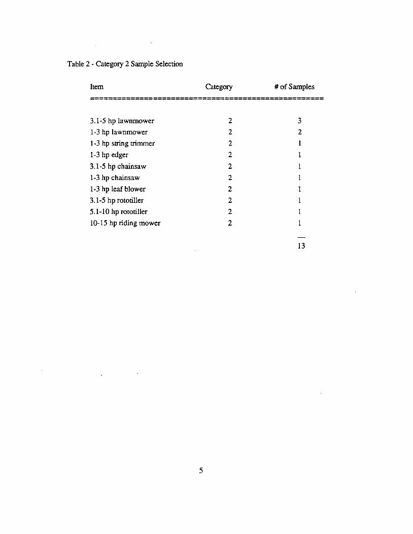
Category 2 sources contain engines with horsepower in the range of 1 to 20. These "utility" engines cover a wide range of applications, as shown in Table I. Category 3 sources, heavy duty equipment, encompass engines from 20 to 99+ horsepower . In addition to determining hydrocarbon composition (as with Category I sources), characterization of aldehyde emissions from these sources was also performed. In order to access the results of previous related studies, a literature search was performed. These references, sorted by year, are shown in Appendix A. Similarly, sorted aldehyde references are listed in Appendix B. The original literature was reviewed for information needed to design the sampling system. A summary of pertinent facts about aldehyde emissions extracted from the literature is shown in Figure 2.
B. Sample Selectiou Criteria
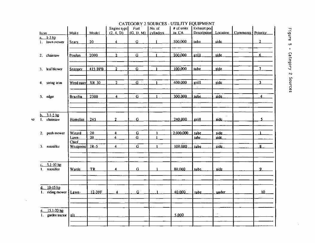
As outlined in the original proposal, a total of twenty sources, distributed approximately equally between Category 2 and Category 3, were to be sampled for hydrocarbon and aldehyde speciation. In order to assign a priority to each item within a given category, information about the population of each item was sought. In 1983, the Mobile Source Control Division of the California Air Resources Board completed an emissions inventory I of equipment in these categories. Values listed in this report were used as a starting point for current California engine populations. A graphical representation of these data (Figure 3) clearly shows the dominance of residential lawn mowers to Category 2 sources. A histogram of engine horsepower ( Figure 4) reveals that most engines are in the 3 to 6 horsepower range. While the number of engine units presently in California is likely not exactly the same as reported by ARB in 1983, evidence will be presented later to support the contention that the 1983 estimates are reasonably close to the current populations. Category 2 sampling information is summarized in Table 2. Based on the large number of
1
lawnmowers in use in California, four of the selected samples were lawnmowers in various configuration and size classes.
A similar analysis was performed for sources in Category 3. Again, earlier ARB estimates were used as a starting point for the populations shown in Figures 5 , 5. and 7. Figures recently tabulated in Implement and Tractor2 listed 1978 and 1988 populations for farm equipment, both nationally as well as from within California. For the number of sources tabulated, the differences between 1978 and 1988 populations were on the order of± 10% . This is illustrated graphically in Figure 7. The dashed line at zero on the graph corresponds to no change in the 1988 population, relative to 1978. A total of 8 sources from Category 3 was selected for sampling. Category 3 sampling information is summarized in Table 3. While Category 3 comprises a large number of equipment types, many of these items contain similar engines. Thus, during the selection process, an attempt was made to focus on engine types, rather than equipment types. For example, industrial tractors utilize engines similar (or identical) to those used in farm tractors. The same is true for many of the other non-farm equipment items. The sources shown in Table 3 were selected on the basis of engine units, rather than equipment units.
2
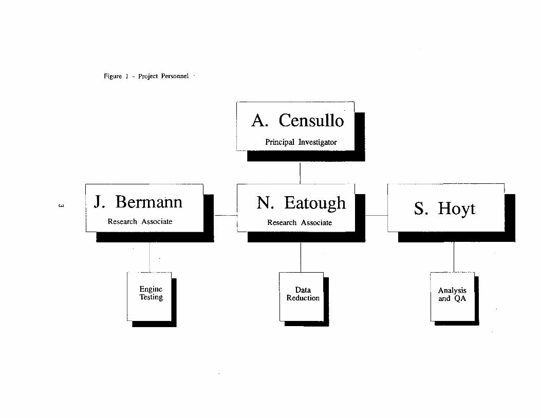
Figure I - Project Personnel ·
w J. Bermahn Research Associate
A. Censullo
N. Eatough Research Associate
S. Hoyt
Engine Data AnalysisTesting Reduction and QA

Table 1 - Category 2 and 3 Sources
CA1EGORY 2 - UTILITY EQUIPMENT EXHAUST
Horsepower
1.0 - 3.0
3.1 - 5.0
5.1 - 10.0
10.1 - 15.0
Commercial
Misc. Lawn and Garden
Chain Saws
Push Mowers
Rototillers
Garden Tractors
Residential
Misc. Lawn and Garden
Chain Saws
Push Mowers
Rototillers
General Utility
Garden Tractors
====================================================== CA1EGORY 3 - HEAVY DUTY EQUIPMENT EXHAUST
FARM
1. Agricultural Tractor, 20-99 hp
2. Agricultural Tractor, 99+ hp
3. Track Type Tractor, 20-89 hp
4. Track Type Tractor, 90+ hp
5. Combine
NON-FARM
1. Tractor, Industrial
2. Ditcher/ Trencher
3. Loader, Wheel Type 2.5 cu. yd
4. Loader, Wheel Type 2.5 + cu. yd.
5. Loader, Track Type , 20-89 hp
6. Loader, Track Type ,90+ hp
7. Tractor, Track Type , 20-89 hp
8.Tractor, Track Type, 90+ hp
6. Windrower
7. Cotton Picker
8. Forage Harvester
9. Track Loader, 20-89 hp
10. Skid Steer Loader
9. Motor Grader
10. Compactor
11. Crane
12. Scraper
13. Excavator
14. Log Skidder
15. Paver
4
--------------
Table 2 - Category 2 Sample Selection
Item
3.1-5 hp lawnmower
1-3 hp lawnmower
1-3 hp string trimmer
1-3 hp edger
3.1-5 hp chainsaw
1-3 hp chainsaw
1-3 hp leaf blower
3.1-5 hp rototiller
5.1-10 hp rototiller
10-15 hp riding mower
Category #of Samples
2 3
2 2
2 1
2 1
2 1
2 1
2 1
2 1
2 1
2 1
13
5
Figure 2
ALDEHYDES IN ENGINE EXHAUST
• 2 - 10 % OF TOTAL HYDROCARBONS WILL BE ALDEHYDES
• 60 -90 % OF ALDEHYDES WILL BE HCHO
• RCHO EMISSIONS IN METHANOL ENGINES IS ROUGHLY 10X THAT OF GASOLINE ENGINES
• ROUGHLY 20 % OF EMITTED ALDEHYDES WILL BE IN TAILPIPE CONDENSATE
• CONCENTRATIONS EXPECTED: 1;.50 PPM IN UNDILUTED EXHAUST
6
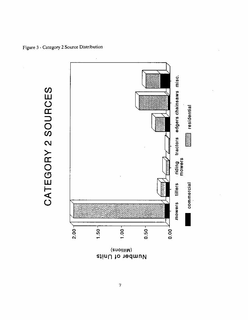
Figure 3 - Category 2 Source Distribution
en w (.) a: ::, 0 en C\J
>a: 0 c:, w J<( (.)
0 0 C\J
0 LO
0 0 .,...
0 LO
0
~
~
0 0 0
0 Cl)
E Cl)
3: CII Cl)
C:
ca ca .r:. ·.;:: 0 C: Cl) CD .... 't:I CD Cl) C) CD
't:I .... CD
Cl) I.... 0-0 ca ....-
Cl) C) .... C: CD ·- 3:'t:I 0 ·.:::: E
Cl) ca.... CD 'ti ....-- CD
E Cl)
e· .... 0 CD 0
3: 0
IE
(SUO!ll!IN)
Sl!Un JO JeqwnN
7
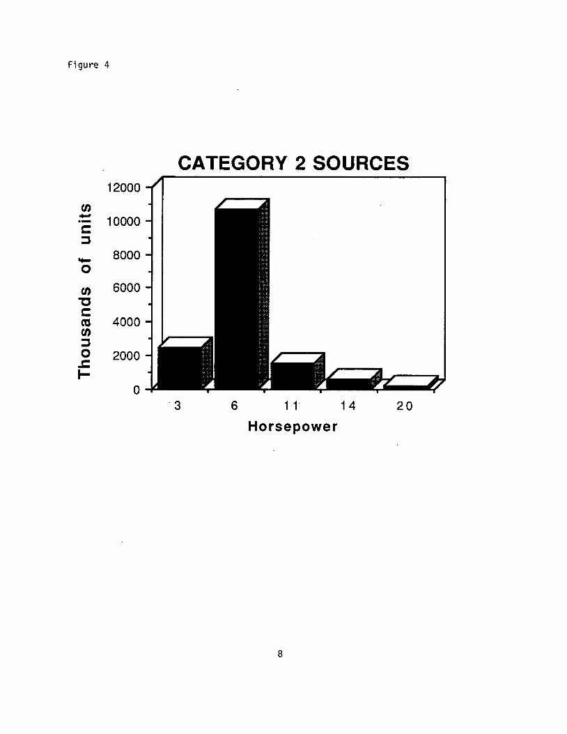
Figure 4
CATEGORY 2 SOURCES 12000
en- 10000s:: ::J
- 8000 0
en 6000 'O s:: as 4000 en ::J 0 2000 .c I-
0 ·3 6 1 1 14 20
Horsepower
8
CATEGORY 2 SOURCES - UTILITY EQUIPMENT
ilem !l, J-3 hp 1. lawnmower
2. chainsaw
3. leaf blower
4. siring trim
5. edger
b, 3,)-5 hp 1. chainsaw"'
2. push mower
3. rototiller
I;, 5.1-IOhl! I. rototiller
!I, IQ-I~ hp I. riding mower
e. 1~,l-20 hp 1. garden tractor
Make
Sear•
Poulan
sn~nn<>r
WPPil ,.,.,,.r
Brazilia
Homelir,-
Wizarcl I -"WO-
Chief Wes1noin1
Ward•
La~n-
all
Model
20
2000
4 l'i BPB
XR 30
2100
24'i
20 20
IR-"i
TR
12-39F
Engine type l2 4 D>
4
?
2
2
4
2
4
4
4
4
4
Fuel lG D M>
G
G
G
G
G
G
r. r.
G
G
G
No. of rvlin,1prs
I
I
I
I
I
I
I
I
I
l
# of units in rA
'\QQ 000
21\/\ Ml\
JQl\lV\Q
4QQMQ
-:ti\/\ Ml\
241l Mil
2 1)/\/\ N\[\
rnQ OQO
RO Ml\
40 1\/lQ
"i 000
Exhaust poi Desrrin•ion
111he
a rill
....._
ara•
111hP
urill
....... ,.,hP
tuhP
JuhP
111hP
Loca•ion
.;,Ip
.;,1,.
oj,lp
•i,lp
•i,1,.
.;,1,.
•i,I,. oiAP
•id"
•i,lp
11ncler
Comm,.nts Prinritv
2
6
7
l
4
"i
l
8
9
rn
-r,~-C: '° ""I <D
01
"' n rt <D
0 ""I '° '< N
V> 0 C: ""I n <D
"'

t. loader.wheel, 2.5+ yd
S. loader, track 20-89 hp
6. loader, track 90+ hp
7. tractor, track 20-89 hp
B. tractor, track 90+ hp
9. motor grader
JO. compactor
..... 0
11. crane
I2. scrapper
13. excavator
14. log skidder
15. paver
John Deen 544 4 D 6
ra, nr..Trn•- 4 n t:.r ... t:.
{'ouolnl
1 2'"'
? Ml/\
,., (l(l(l
,., /;/\(l
,., 1\/\/\
1 1\/\/\
A 1\/\/\
,, 1\/\
I ~/\/\
1 (l(l(l
I 1\/\/\
I 1\/\/\
•on'"b"'
lnn.nn'"""'
"Tl~. <O
..,C:
(I)
a,
n O> ..... (I)
<O ..,0
'< w V, 0
..,C:
0 (I) VI

CATEGORY 3 SOURCES - HEAVY DUTY EQUIPMENT
hem a. FARM I . tractor 20-99h(
2. tractor 99+ hp
3. track tractor 20-98 hp
4. track tractor 90+ hp
5. combine
6. windrower
..... ..... 7. couon picker
8. fooige harvesier
9. track loader 20-98 hp
I 0. skid steer
b, liQliEARM I. tractor,
industrial
2. ditcher and trencher
3. loader.wheel, 2,4 yd
Engine type Fuel No. of # of units Exhaust pm Make Moclel (2 4 D) (G.D. M) rulin.-l"r• in CA n..•crintion I nrotion
Ford 9N 4 G 4 1\0 000 lnhP. nntt,-r
IHC 656 4D D 6 14 'iO0 tnh,- 1on-11n
Cat D6-9V 4D D " ? 'iOO rnhe tnn.nn
Cal n/\.C 40 D 6 6 000 tuhe tnn-un
lnhn n,-,.., 7720 40 D 6 5 000 luhe tnn.un
New 111? 4 G " 'i OflO lnhl' tnn.11n J.lnll,.ncl
ah 'i 000
1\00
700
Ni,w I -'i 'i 'i 4 n 4 ? 'iOO tnhl' harlc J.lnll~ncl
10 000
f\ovi• 10...4 4 r. 4 4 000 lube nntt,.,
1 'iOO
Commenr. Priori1v
I
3
4
'i
r.
?.
7
.,,~-<O ..,C:
m .......
n !>I .-+ m
'° ..,0
'< w ~ 0 C:.., n <1) V>
n 0 ~ .-+~. ~ C: <1)
a.
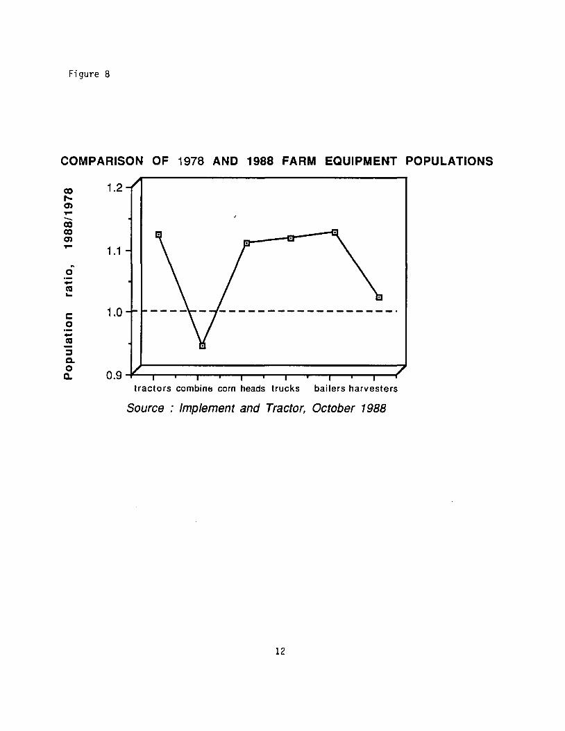
Figure 8
COMPARISON OF 1978 AND 1988 FARM EQUIPMENT POPULATIONS
1.2co ..... a, ,.. co--co a, ,..
1.1 ft
0-ca... 1.0C:
0-ca ::, 0.
a. 0 0.9 ....,...--,,--""T"-....---.--...-----.---r--....--.--...---.----r
tractors combin6 corn heads trucks bailers harvesters
Source : Implement and Tractor, October 1988
12

---
Table 3 - Category 3 Sample Selection
Item no. of samples Priority
Farm Tractor, 20-99 hp 2 1
Farm Tractor, 99+ hp 2 2
Farm Track Tractor, 90+hp 1 3
Combine 1 4
Windrower 1 5
Ditcher/ Trencher 1 6
8
1 3
C. Samplin~ Methodolo~
1. Samplin~ Tunnel Desiiro
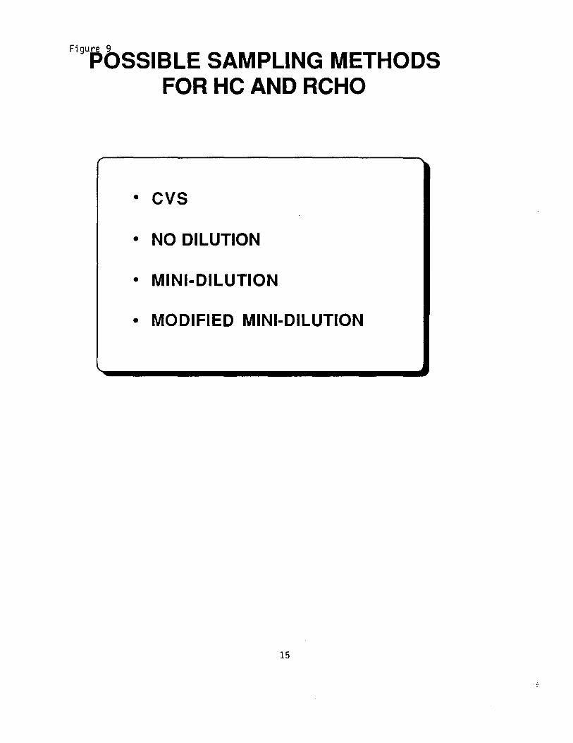
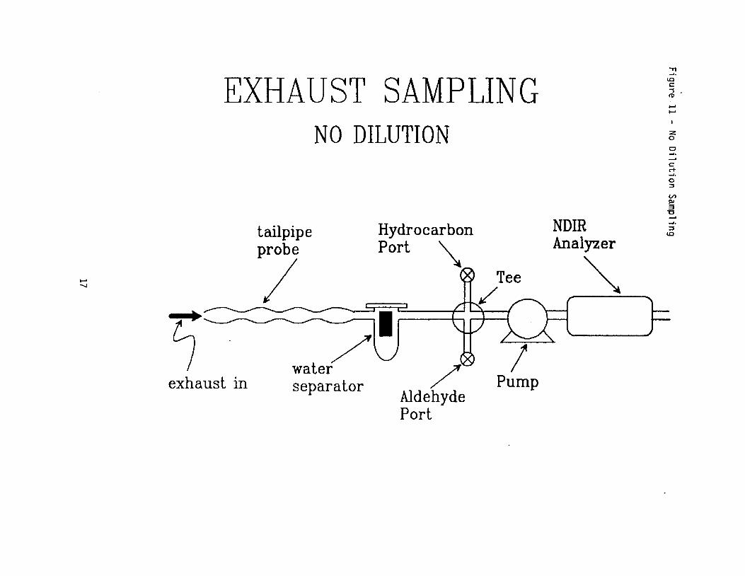
The sampling method selected for this work evolved according to the path illustrated in Figure 9 The classical approach to sampling vehicle emissions is to use a constant volume sampling (CVS) system, in conjunction with a chassis dynamometer. The engine is typically operated at a variety of speeds, as with the Federal Test Program, and all exhaust is led into a dilution tunnel. Diluted exhaust is pulled through the tunnel at 650 CFM. Baugh3 used this method to sample aldehydes in automobile exhaust (Figure 10). For the types of engines to be tested in this project, the CVS system was too cumbersome to be practical. The CVS system is essentially a variable-dilution system, necessitated by the fact that the test engine is operated at a variety of speeds. An alternative to the CVS test method would involve operating the engine at constant load (hence, constant emissions), and using a constant (or no) dilution factor. The sampling system would have to incorporate probes for both hydrocarbon and aldehyde samples. The analytical requirements for these two classes of compounds demanded separate sampling trains. With simplicity and portability as important factors, the sampling system illustrated in Figure 11 was considered. It was based on a minor modification of a Sun MGA-90 analyzer (Figure 12). Complications arising from the analysis of the water separator contents ultimately lead to the rejection of this design.
The fabrication and operation of a dilution mini-tunnel was described by MacDonald4 (see Figure 13). From this project's point of view, the tunnel had several advantages over other designs. It was small enough to be portable (less than 6 feet overall), and required no pump to pull diluted exhaust through it. These were important characteristics, since the testing apparatus may need to be transported to where the test engines were located. The modification of MacDonald's design used in this project is shown in Figure 14. The dilution nozzle was machined from a solid block of aluminum, and turned to provide a shoulder for attachment of upstream and downstream portions of the tunnel. These sections sealed with an 0-ring into the nozzle section, and could be easily removed for cleaning or transportation. Instead of having the exhaust pulled through the system with a vacuum pump (as with CVS), this mini-tunnel used a pressurized zero air source upstream of the nozzle. Nozzle dimensions were selected that allowed sonic flow through the throat. The low pressure in the nozzle throat "pulled" exhaust into the tunnel. In the original reference, Mac Donald verified the absence of stratification with this design. A series of wall-to-wall traverses revealed essentially no variation in sampled C(h concentrations in the tunnel. Unlike the CVS system, only a portion of the total engine exhaust was led into the tunnel. Since the volume of exhaust handled was comparatively low, comparably low volumes of dilution air were needed to produce a 10:1 dilution. Thus, zero air from a compressed gas cylinder was used as a source of dilution air. During operation, a back pressure valve was adjusted to maintain a slight positive (about 1 inch of water) pressure at the downstream end of the tunnel. This prevented outside air from entering the tunnel through any small leaks that may have been present. Diluted exhaust leaving the tunnel was led away from the test engine by a flexible duct to prevent its re-combustion by the engine. The COi content of the raw and diluted exhaust was determined by a Sun MGA-90 NDIR analyzer.
14
FiguPQSSIBLE SAMPLING METHODS FOR HC AND RCHO
r
• CVS
• NO DILUTION
• MINI-DILUTION
• MODIFIED MINI-DILUTION
15

Figure 10 - CVS Sampling Scheme
TO NEAT EXCHANGER,
FLOW CONTROLLER
HCNO INJECTION APl"ARATUS
HEATING COil
MIXING
INSULATED ENCLOSURE
n FAN
I
COIL
CHASSIS OYNAMOMETER
WIT TUT
METER
HIATIO llNI
COLO CELL ENCLOIURI
'-V- AOAl"TEII
HUTED TRANSFER LINE
CVS. AND l"DI",
OILUTIOII n,an
Test cell configuration.
16
EXHAUST SAMPLING NO DILUTION
tailpipe Hydrocarbon Port ~pi
...... ......
/.I0 water exhaust in separator
"Tl~. <C C: -s <D
..... .....
:z 0
0~~
C: <+~. 0 :::,
V, cu 3
"'C
~-:::,NDIR ~
<C
Analyzer
Pump
~
Aldehyde Port
FIGURE 18- SUN MGA-90 ANALYZER
I "TlLow ~-FlowINFRA-RED EXHAUST PERFORMANCE ANALYZER lOLight C -s c:,
.....Low Flow IVa.::uumZero 11Switch Swiech,,(,,,
N
1./l C
Sample E )(haun :zTallplpe Water Soparacor
& Pri. Fill er
A~piriltOr
Socondaryfrom Tailpipe Probo F iltcr
~ );,Samµlo Gas from I0oulc or \DAtmosphere
Aspirator K) I Atmo1phuo 0
l'u1np );,Water ::,Olsch,rge ~· Sample ExhaustOhcharped Portto Atmosphere
lnfra-Rr.d Infra-RodSample Dotoc1or..... Coll - ""' - - - - - - - - ~ (Tuned) Flit or I
c=, , r- - - · HC for HC
' ' , / Span Calibration 'IA J( /Switch fl.JgSourco
/ ' ,, ' ,------~ / ' lnfn,Aca Infra-Red --~ Rolcrvnco ~--L' '--- (Tuned) F iltor Dc,ectur
Chopper
Coll -------- co for CO
On-Off Signol & Ref.Switch Svnc's.oc
Power Supply
BLOCK DIAGRAM Overload Line Cord Protector for Local Oe\llce Power
--i> PNEUMATIC_. ELECTRICAL ~~~!._'?_co_RPORATION----) OPTICAL
,"\c;r,-~o
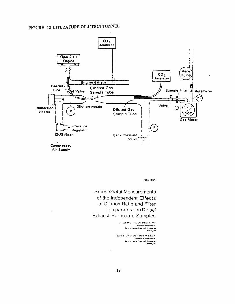
FIGURE 13- LITERATIJRE DILUTION TIJNNEL
CO2 Analyzer
I CO2 l Analvzer I
I I I
;
d 8
Sample Filter ~ Rotimeter
Diluted Gas Sample Tube
Back Pressure Va1Y11
-0
\lalYe
Compressed Air Supply
000105
Experimental Measurements of the Independent Effects of Dilution Ratio and Filter
Temperature on Diesel Exhaust Particulate Samples
J_ Sc011 r., .... OonM<J ,1...:I St,r,ne,n l.. r1,.-e
19
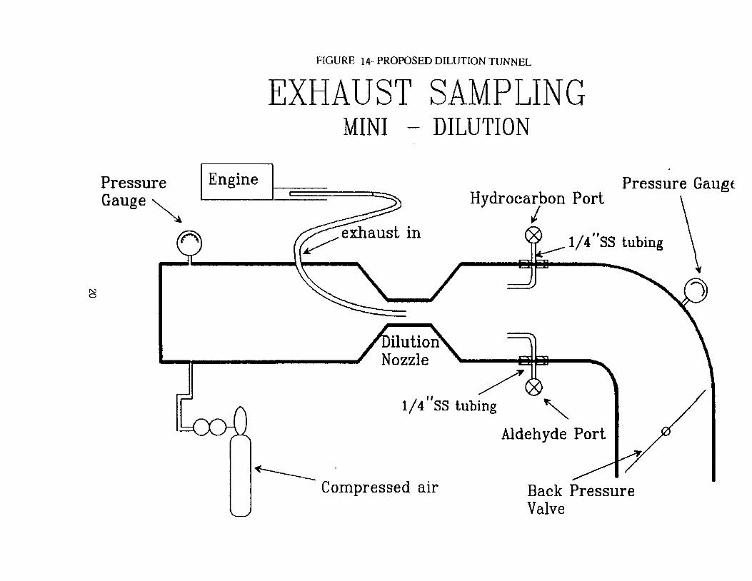
FIGURE 14- PROPOSED DILUTION TUNNEL
EXHAUST SAMPLING MINI - DILUTION
EnginePressure Pressure Gaugf Gauge~
st in
OZZle
I
N 0
11
1/4 SS tubing "-
~ Compressed air Back Pressure
Valve
Hydrocarbon Port
1/4"ss tubing
Aldehyde Port
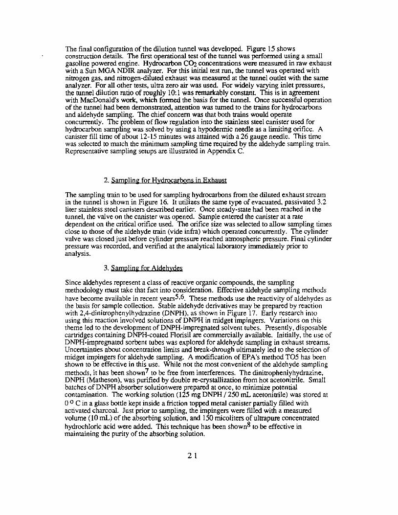
The final configuration of the dilution tunnel was developed. Figure 15 shows construction details. The first operational test of the tunnel was performed using a small gasoline powered engine. Hydrocarbon COi concentrations were measured in raw exhaust with a Sun MGA NDIR analyzer. For this initial test run, the tunnel was operated with nitrogen gas, and nitrogen-diluted exhaust was measured at the tunnel outlet with the same analyzer. For all other tests, ultra zero air was used. For widely varying inlet pressures, the tunnel dilution ratio of roughly 10: 1 was remarkably constant This is in agreement with MacDonald's work, which formed the basis for the tunnel. Once successful operation of the tunnel had been demonstrated, attention was turned to the trains for hydrocarbons and aldehyde sampling. The chief concern was that both trains would operate concurrently. The problem of flow regulation into the stainless steel canister used for hydrocarbon sampling was solved by using a hypodermic needle as a limiting orifice. A canister fill time of about 12-15 minutes was attained with a 26 gauge needle. This time was selected to match the minimum sampling time required by the aldehyde sampling train. Representative sampling setups are illustrated in Appendix C.
2. Samplinfi for Hydrocarbons in Exhaust
The sampling train to be used for sampling hydrocarbons from the diluted exhaust stream in the tunnel is shown in Figure 16. It utilizes the same type of evacuated, passivated 3.2 liter stainless steel canisters described earlier. Once steady-state had been reached in the tunnel, the valve on the canister was opened. Sample entered the canister at a rate dependent on the critical orifice used. The orifice size was selected to allow sampling times close to those of the aldehyde train (vide infra) which operated concurrently. The cylinder valve was closed just before cylinder pressure reached atmospheric pressure. Final cylinder pressure was recorded, and verified at the analytical laboratory immediately prior to analysis.
3. Samplio!i for Aldehydes
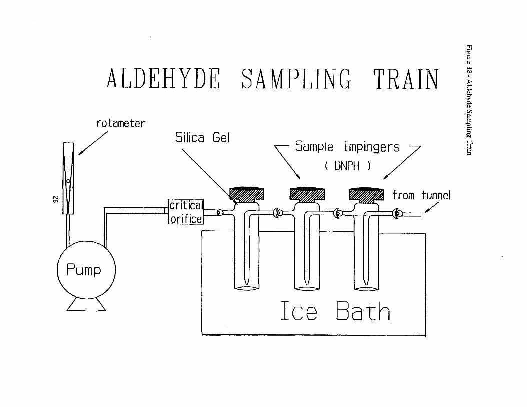
Since aldehydes represent a class of reactive organic compounds, the sampling methodology must take that fact into consideration. Effective aldehyde sampling methods have become available in recent years5,6_ These methods use the reactivity of aldehydes as the basis for sample collection. Stable aldehyde derivatives may be prepared by reaction with 2,4-dinitrophenylhydrazine (DNPH), as shown in Figure 17. Early research into using this reaction involved solutions of DNPH in midget impingers. Variations on this theme led to the development of DNPH-impregnated solvent tubes. Presently, disposable cartridges containing DNPH-coated Florisil are commercially available. Initially, the use of DNPH-impregnated sorbent tubes was explored for aldehyde sampling in exhaust streams. Uncertainties about concentration limits and break-through ultimately led to the selection of midget impingers for aldehyde sampling. A modification of EPA's method TO5 has been shown to be effective in this use. While not the most convenient of the aldehyde sampling methods, it has been shown? to be free from interferences. The dinitrophenlyhydrazine, DNPH (Matheson), was purified by double re-crystallization from hot acetonitrile. Small batches ofDNPH absorber solutionwere prepared at once, to minimize potential contamination. The working solution (125 mg DNPH / 250 mL acetonitrile) was stored at 0 °Cina glass bottle kept inside a friction topped metal canister partially filled with activated charcoal. Just prior to sampling, the impingers were filled with a measured volume (10 mL) of the absorbing solution, and 150 rnicoliters of ultrapure concentrated hydrochloric acid were added. This technique has been shown8 to be effective in maintaining the purity of the absorbing solution.
2 1
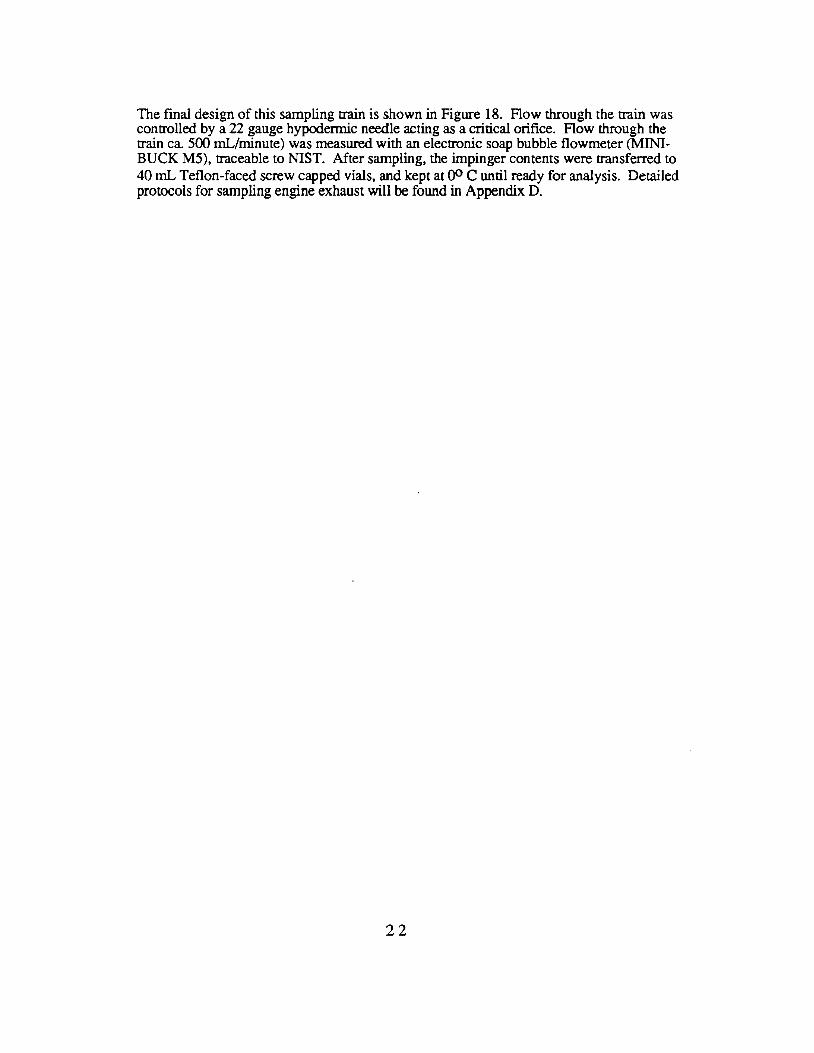
The final design of this sampling train is shown in Figure 18. Flow through the train was controlled by a 22 gauge hypodermic needle acting as a critical orifice. Flow through the train ca. 500 mL/minute) was measured with an electronic soap bubble flowmeter (MINIBUCK MS), traceable to NIST. After sampling, the impinger contents were transferred to 40 mL Teflon-faced screw capped vials, and kept at 00 C until ready for analysis. Detailed protocols for sampling engine exhaust will be found in Appendix D.
22
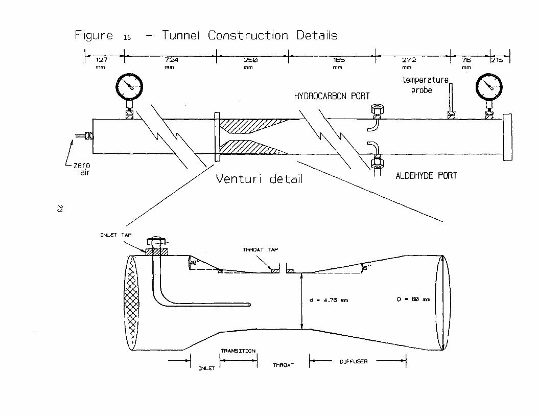
Figure 15 - T unne I Construct ion Details
I· 127 -I · ·I· 250 · I · 185 I I 272 I· 76 • l216 ·I724 mm mm mm mm mm mm
N w
L,er.□ air
"l HYDROCARBON PORT
Venturi detail
temperature probe n ''
ALDEHYDE PORT
----1
TtflOAT TAP
d = 4.76 nm D • 60 nvn
,:RAN5ITION r-- DIFFUSERTHROATINLET ·I ~

Figure 16
HYDROCARBON SAMPLING TRAIN
/Hydrocarbon Port
L-"'"______ Glass Wool Plug
___Critical Orifice
__- Stainless Steel ~ Canister
24
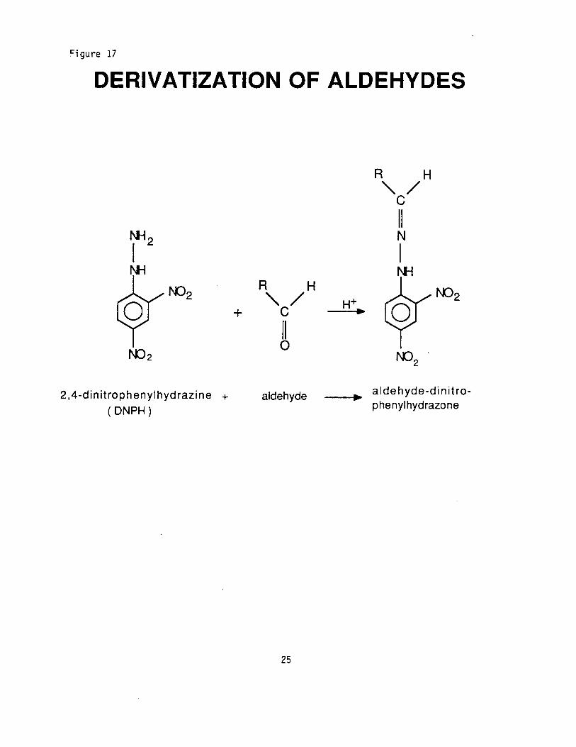
~igure 17
DERIV ATIZATION OF ALDEHYDES
R H '/C
II NN12
I I N;
R H "/ H++ C .,
II 0
_.,.., aldehyde-dinitro-2,4-dinitrophenylhydrazine + aldehyde phenylhydrazone( DNPH)
25
:TI (IQ
..... co
►ALDEHYDE SAMPLING TRAIN @
i ~
rotameter ig:
[/)
(JQSilica Gel ~ Sample Impinge7s
---3/ ~-"\ ( DNPH )
N a, cri.ti~a~~?~;1· ~;;T ____ from tunnel
onfice ~ ~"=::J ,----L--,®r-== /
Ice Bath
4. Sampling for High Molecular Weight Hydrocarbons
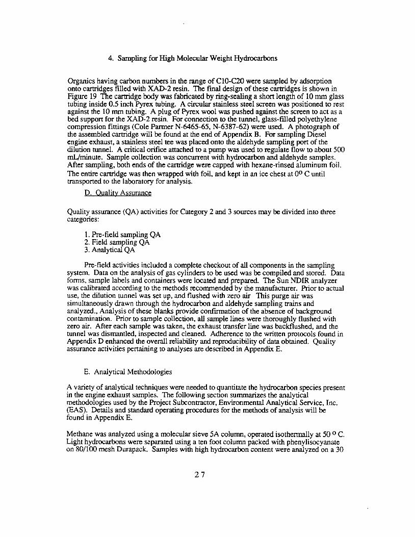
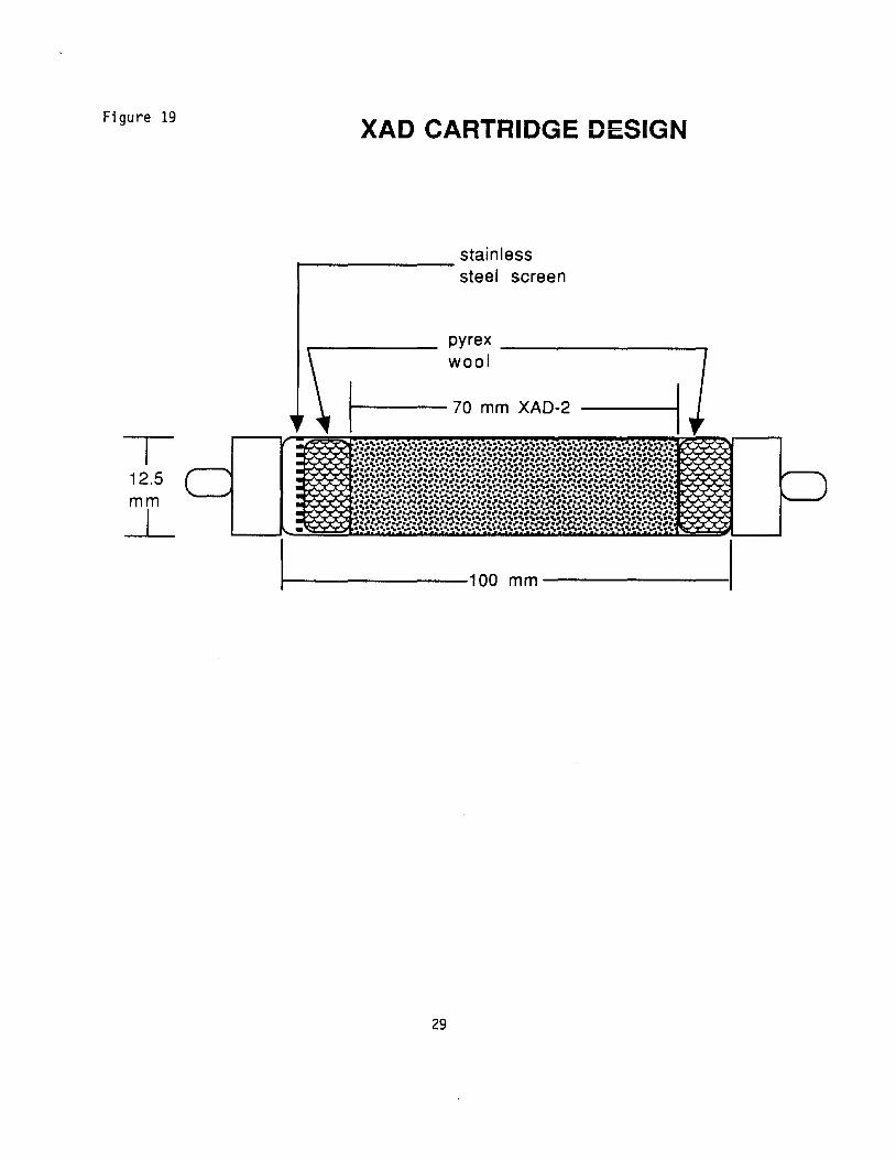
Organics having carbon numbers in the range of C10-C20 were sampled by adsorption onto cartridges filled with XAD-2 resin. The final design of these cartridges is shown in Figure 19 The cartridge body was fabricated by ring-sealing a short length of 10 mm glass tubing inside 0.5 inch Pyrex tubing. A circular stainless steel screen was positioned to rest against the 10 mm tubing. A plug of Pyrex wool was pushed against the screen to act as a bed support for the XAD-2 resin. For connection to the tunnel, glass-filled polyethylene compression fittings (Cole Parmer N-6465-65, N-6387-62) were used. A photograph of the assembled cartridge will be found at the end of Appendix B. For sampling Diesel engine exhaust, a stainless steel tee was placed onto the aldehyde sampling port of the dilution tunnel. A critical orifice attached to a pump was used to regulate flow to about 500 mLJminute. Sample collection was concurrent with hydrocarbon and aldehyde samples. After sampling, both ends of the cartridge were capped with hexane-rinsed aluminum foil. The entire cartridge was then wrapped with foil, and kept in an ice chest at o° C until transported to the laboratory for analysis.
D. Quality Assurance
Quality assurance (QA) activities for Category 2 and 3 sources may be divided into three categories:
1. Pre-field sampling QA 2. Field sampling QA 3. Analytical QA
Pre-field activities included a complete checkout of all components in the sampling system. Data on the analysis of gas cylinders to be used was be compiled and stored. Data forms, sample labels and containers were located and prepared. The Sun NDIR analyzer was calibrated according to the methods recommended by the manufacturer. Prior to actual use, the dilution tunnel was set up, and flushed with zero air This purge air was simultaneously drawn through the hydrocarbon and aldehyde sampling trains and analyzed., Analysis of these blanks provide confirmation of the absence of background contamination. Prior to sample collection, all sample lines were thoroughly flushed with zero air. After each sample was taken, the exhaust transfer line was backflushed, and the tunnel was dismantled, inspected and cleaned. Adherence to the written protocols found in Appendix D enhanced the overall reliability and reproducibility of data obtained. Quality assurance activities pertaining to analyses are described in Appendix E.
E. Analytical Methodologies
A variety of analytical techniques were needed to quantitate the hydrocarbon species present in the engine exhaust samples. The following section summarizes the analytical methodologies used by the Project Subcontractor, Environmental Analytical Service, Inc. (EAS). Details and standard operating procedures for the methods of analysis will be found in Appendix E.
Methane was analyzed using a molecular sieve 5A column, operated isothennally at 50 ° C. Light hydrocarbons were s.:parated using a ten foot column packed with phenylisocyanate on 80/100 mesh Durapack. Samples with high hydrocarbon content were analyzed on a 30
27

foot column containing 23 % SP-1700 on 80/100 mesh Chromosorb PAW. Heavy hydrocarbons were analyzed using a 100 meter fused silica capillary column.
Comparison of the light (packed column) and heavy hydrocarbon (capillary column) runs could be made using a number of peaks in the C2 to C4 range. The heavy stationary phase loading of the 100 meter capillary column allowed for the separation of the lighter hydrocarbons. Initially, values for the light hydrocarbons (from C2 on) obtained from the integrator output of the capillary column run were used for calculations. A review of the results so obtained indicated some inconsistencies in the light hydrocarbon concentrations of some samples. When the chromatograms were examined in detail, there was some ambiguity assigned with ethane, ethylene and acetylene peaks, due to insufficient resolution of these components for these samples. Values for all engine samples in this report were re-calculated using concentration information obtained from the packed column light hydrocarbon runs for ethane, ethylene and acetylene.
The method used for analysis of aldehydes was a modification to EPA method TQ59, which is functionally similar to CARB method 11010 The sampling method was based on the reaction of DNPH in acidified acetonitrile with aldehydes and ketones to form stable hydrazone derivatives. For analysis, an aliquot of the impinger contents was injected onto a Supelcosil LC18 reverse phase column. The system was run isocratically, using a mobile phase consisting of 70 % acetonitrile and 30 % water. The aldehyde derivatives were detected by a UV-Visible detector operating at 360 nm, and quantitated on an HP 3393A computing integrator. Details of the analyses may be found in Appendix E.
Since the carbon number limitation for the SUMMA canisters is ClO or Cl 1, an additional sampling train was used to retain higher molecular weight hydrocarbons in the ClO to C20 range. A glass cartridge, filled with XAD-2 resin was used for this purpose. The XAD-2 resin is the material recommended by the California Air Resources Board (CARB) for source sampling of semi-volatile organic compounds. The procedures used for extraction and analysis of the cartridges are described in CARB Method 429 "Determination of Polycyclic Aromatic Hydrocarbon Emissions from Stationary Sources".
28
----------
Figure 19 XAD CARTRIDGE DESIGN
stainless steel screen
T 12.5 mm __L
pyrex ------------, wool
f--- 70 mm XAD-2
1----------100 mm ---------1
29
F. Engine Sampling
Using the dilution tunnel described previously, 21 engine tests were performed. Table 4 shows the engines tested and the corresponding analytical samples taken. Volatile hydrocarbon and aldehyde samples were taken for all engines. Hydrocarbon samples were collected in evacuated, SUMMA polished stainless steel canisters. Aldehydes were collected in midget impingers, filled with DNPH-acetonitrile, using the methodology described previously. Semi-volatile hydrocarbons from the last 8 tests were collected on XAD-2 cartridges, as outlined earlier. Selected sampling setups are shown in Appendix C. All sub-systems used for the tests functioned perfectly, and 100% of samples were successfully obtained.
All engines were tested "as received", with no special tuning, and were thus typical of "inuse" condition. Exhaust samples were taken under conditions that classify them as "spot" samples. Engines were warmed up prior to sampling, then maintained at full throttle or rated speed for the duration of the test (typically about 20 minutes). Utility engines were fueled immediately prior to sampling, to ensure sufficient fuel to complete the test without interruption. Mixtures for 2 stroke engines were blended immediately before fueling the engines. Manufacturer recommendations were followed for fuel mixtures. Two stroke engines corresponding to samples ET-1, 3 and 4 used a 25:l, while ET-9 used a 32:l ratio. Fuel (EXXON unleaded gasoline, temp 80, grav. 58.0, octane 87; ARCO diesel fuel, DSL-LS) for all engines was from the Cal Poly motor pool.
30
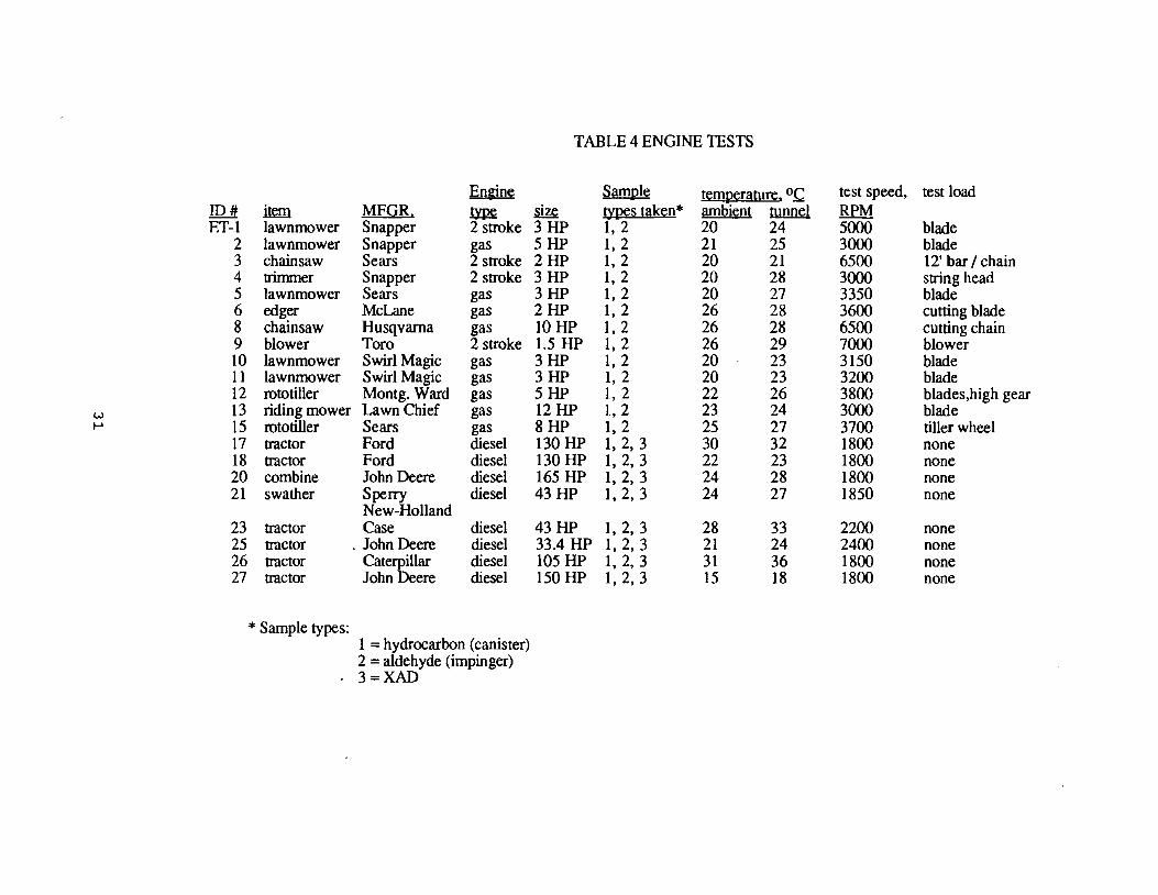
TABLE 4 ENGINE TESTS
En&in!. Sam11I!. t!.m11erarure, 0.C test speed, test load ID# mm MFGR. ~ size tj'.12!.S tak~n* ambient tunnel RPM ET-1 lawnmower Snapper 2 stroke 3 HP 1, 2 20 24 5000 blade
2 lawnmower Snapper gas 5 HP 1, 2 21 25 3000 blade 3 chainsaw Sears 2 stroke 2 HP 1, 2 20 21 6500 12' bar/ chain 4 trimmer Snapper 2 stroke 3 HP 1, 2 20 28 3000 sning head 5 lawnmower Sears gas 3 HP I, 2 20 27 3350 blade 6 edger McLane gas 2HP 1, 2 26 28 3600 cutting blade 8 chainsaw Husqvarna gas lOHP 1, 2 26 28 6500 cutting chain 9 blower Toro 2 stroke 1.5 HP 1, 2 26 29 7000 blower 10 lawnmower Swirl Magic gas 3HP 1, 2 20 23 3150 blade 11 lawnmower Swirl Magic gas 3 HP l, 2 20 23 3200 blade 12 rototiller Montg. Ward gas 5 HP l, 2 22 26 3800 blades,high gear
w 13 riding mower Lawn Chief gas 12 HP l, 2 23 24 3000 blade I-' 15 rototiller Sears gas 8HP l, 2 25 27 3700 tiller wheel
17 tractor Ford diesel 130 HP 1, 2, 3 30 32 1800 none 18 tractor Ford diesel 130 HP 1, 2, 3 22 23 1800 none 20 combine John Deere diesel 165 HP 1, 2, 3 24 28 1800 none 21 swather Sperry diesel 43 HP 1, 2, 3 24 27 1850 none
New-Holland 23 tractor Case diesel 43 HP I, 2, 3 28 33 2200 none 25 tractor . John Deere diesel 33.4 HP I, 2, 3 21 24 2400 none 26 tractor Caterpillar diesel 105 HP I, 2, 3 31 36 1800 none 27 tractor John Deere diesel 150 HP 1, 2, 3 15 18 1800 none
* Sample types: 1 = hydrocarbon (canister) 2 = aldehyde (irnpinger) 3=XAD
G. Format for Results
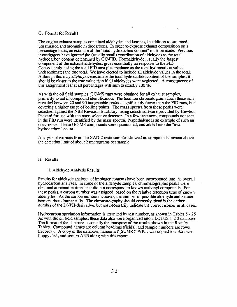
The engine exhaust samples contained aldehydes and ketones, in addition to saturated, unsaturated and aromatic hydrocarbons. In order to express exhaust composition on a percentage basis, an estimate of the "total hydrocarbon content" must be made. Previous investigators have ignored the (usually small) contribution of aldehydes to the total hydrocarbon content determined by GC-FID. Formaldehyde, usually the largest component of the exhaust aldehydes, gives essentially no response to the FID. Consequently, using the total FID area plus methane as the total hydrocarbon value underestimates the true total. We have elected to include all aldehyde values in the total. Although this may slightly.overestimate the total hydrocarbon content of the samples, it should be closer to the true value than if all aldehydes were neglected. A consequence of this assignment is that all percentages will sum to exactly 100 %.
As with the oil field samples, GC-MS runs were obtained for all exhaust samples, primarily to aid in compound identification. The total ion chromatograms from these runs revealed between 20 and 90 integratable peaks - significantly fewer than the FID runs, but covering a higher range of boiling points. The mass spectra from these peaks were searched against the NBS Revision E Library, using search software provided by Hewlett Packard for use with the mass selective detector. In a few instances, compounds not seen in the FID run were identified by the mass spectra. Naphthalene is an example of such an occurrence. These GC-MS compounds were quantitated, and added into the "total hydrocarbon" count.
Analysis of extracts from the XAD-2 resin samples showed no compounds present above the detection limit of about 2 micrograms per sample.
H. Results
1. Aldehyde Analysis Results
Results for aldehyde analyses of impinger contents have been incorporated into the overall hydrocarbon analyses. In some of the aldehyde samples, chromatographic peaks were obtained at retention times that did not correspond to known carbonyl compounds. For these peaks, a carbon number was assigned, based on the relative retention time of known aldehydes. As the carbon number increases, the number of possible aldehyde and ketone isomers rises dramatically. The chromatography should correctly identify the carbon number of the DNPH-derivative, but not necessarily indicate the correct isomer in all cases.
Hydrocarbon speciation information· is arranged by test number, as ~hown in Tables 5 - 25 As with the oil field samples, these data also were organized into a LOTUS 1-2-3 database. The format of the database is actually the transpose of the results shown in the Results Tables. Compound names are column headings (fields), and sample numbers are rows (records). A copy of the database, named ET_SUMRY.WKl, was copied to a 3.5 inch floppy disk, and sent to ARB along with this report.
32

Table 5 - ET-01 Snapper lawnmower (2 stroke 3 hp) Compound % by mass
Compound % by mass
Methane 1.4829 Ethylene 0.1807 Ethane 0.0875 Acetylene 0.4540 Propene 1.1280
Propane 0.1585 Methylacetylene 0.0000 i-Butane 0.3654 methanol 0.0000 i-butylene 0.5364 I-butene 0.6358 1,3-Butadiene 0.0000
n-Butane 0.1441 trans-2-butene 0.0000 2,2-dimethylpropane 0.0000 cis-2-butene 0.0000 ethanol 0.0000 i-Pentane 4.5419 1-pentene 0.3563
n-Pentane 2.1211 trans-2-pentene 0.8005 cis-2-pentene 1.1799 2,2-Dimethylbutane 1.9795 Cyclopentane 0.8413 2,3-Dimethylbutane 0.0000 2-Methylpentane 3.4758 3-Methylpentane 2.2253
n-Hexane 1.9756 Methylcyclopentane 2.4578 2,4-Dimethylpentane 0.5887 Benzene 4.6134 Cyclohexane 0.0000 2-Methylhexane 1.9790 2,3-Dimethylpentane 0.7093 3-Methylhexane 2.0083 2,2,4-trimethylpentane 0.5988
n-Heptane 1.5458 Methylcyclohexane 0.3333 2,4-Dimethylhexane 0.5638 2,3,4-Trimethylpentane 0.8519 Toluene 15.3360 2,3-Dimethylhexane 0.3799 2-Methylheptane 1.0896 3-Ethylhexane 1.0560
n-Octane 0.8711 Ethylbenzene 3.4988 m-Xylene 9.3262 p-Xylene 0.0000 Styrene 0.8656 a-Xylene 3.7281
n-Nonane 0.5244 i-Propylbenzene 0.0000 n-Propylbenzene 0.4799 3-Ethyltoluene 0.0000
1,3,5-Trimethylbenzene 0.6379 2-Ethyltoluene 0.4570 t-butylbenzene 0.0000 1,2,4-Trimethylbenzene 0.7679 i-butylbenzene 0.0000 s-butylbenzene 0.0000
n-Decane 0.0000 1,2,3-Trimethylbenzene 0.0000 indane 0.0000 1,3-Diethylbenzene 0.0000 1,4-Diethylbenzene 0.0000 n-butylbenzene 0.0000 1,2-Diethylbenzene 0.0000 1,4-dimethyl-2-ethylbenzene 0.0000 1,3-dimethyl-4-ethylbenzene 0.0000 1,2-dimethyl-4-ethylbenzene 0.0000 1,3-dimethyl-2-ethylbenzene 0.0000
n-undecane 0.0000 1,2,3,5-tetramethylbenzene 0.0000 1,2,4,5-tetramethylbenzene 0.0000
O11-IER COMPOUNDS
2-propenylbenzene 0.0000 1,2-dichlorobenzene 0.0000 2-methylstyrene 0.0000 l-ethynyl-4-methylbenzene 0.0000 naphthalene 0.0000
OXYGENATES
formaldehyde 0.0101 acetaldehyde 0.0473 acetone 0.0203 propanal 0.0144 MEK 0.0128 butanal 0.0113 2&3-pentanone 0.0040 cyclohexanone 0.0026 pentanal 0.0050 4-methyl-2-pentanone 0.0036 2-methyl-3-pentanone 0.0031 hexanal 0.0227 benzaldehyde 0.0165 C4 ketone 0.0107 C6 ketone 0.0000 tolualdehyde ? 0.0000
Other C2 3.8019 Other C3 0.0000 Other C4 1.1372 Other C5 2.0035 OtherC6 5.7967 OtherC7 4.0329 Other C8 1.3153 Other C9 1.7893 Other ClO 0.0000 OtherCll 0.0000
33

Table 6- ET-02 Snapper lawnmower (5 hp) Compound % by mass
Compound %by mass·
Methane 4.7186 Ethylene 9.4642 Ethane 1.2474 Acetylene 6.6440 Propene 3.4685
Propane 3.6475 Methylacetylene 0.6442 i-Butane 0.2177 methanol 0.2138 i-butylene 1.3349 I-butene 0.5148 1,3-Butadiene 1.2605
n-Butane 0.7184 trans-2-butene -0.0000 2,2-dimethylpropane 0.0000 cis-2-butene 0.0000 ethanol 0.0706 i-Pentane 0.9304 1-pentene 0.1802
n-Pentane 0.9361 trans-2-pentene 0.0000 cis-2-pentene 0.0000 2,2-Dimethylbutane 0.0751 Cyclopentane 0.2237 2,3-Dimethylbutane 0.0000 2-Methylpentane 0.5015 3-Methylpentane 0.6814
n-Hexane 2.0254 Methylcyclopentane 0.9247 2,4-Dimethylpentane 0.1637 Benzene 7.5099 Cyclohexane 0.0000 2-Methylhexane 0.4718 2,3-Dimethylpentane 0.1997 3-Methylhexane 0.5277 2,2,4-trimethylpentane 0.2225
n-Heptane 0.3772 Methylcyclohexane 0.3670 2,4-Dime thylhexane 0.2204 2,3,4-Trimethylpentane 0.1351 Toluene 8.6677 2,3-Dimethylhexane 0.0000 2-Methylheptane 0.1802 3-Ethylhexane · 0.0000
n-Octane 0.2099 Ethylbenzene 1.6234 m-Xylene 4.8396 p-Xylene 0.0000 Styrene 0.0000 o-Xylene 2.1508
n-Nonane 0.9923 i-Propylbenzene 0.0000 n-Propylbenzene 0.0000 3-Ethyltoluene 0.0000
1,3,5-Trimethylbenzene 0.8499 2-Ethyltoluene 0.7615 t-butylbenzene 0.0000 1,2,4-Trimethylbenzene 3.2903 i-butylbenzene 0.0000 s-butylbenzene 0.0000
n-Decane 1.1394 1,2,3-Trimethylbenzene 0.0000 indane 0.6161 1,3-Diethylbenzene 0.0000 1,4-Diethylbenzene 0.4103 n-butylbenzene 0.2292 1,2-Diethylbenzene 0.0000 1,4-dimethyl-2-ethylbenzene 0.3414 1,3-dimethyl-4-ethylbenzene 0.2887 1,2-dimethyl-4-ethylbenzene 0.0000 1,3-dimethyl-2-ethylbenzene 0.0000
n-undecane 0.0000 1,2,3,5-tetramethylbenzene 0.0000 1,2,4,5-tetramethylbenzene 0.0000
OTHER COMPOUNDS
2-propenylbenzene 0.0000 1,2-dichlorobenzene 0.0000 2-methylstyrene 0.0000 l-ethynyl-4-methylbenzene 0.0000 naphthalene 0.0000
OXYGENATES
formaldehyde 0.5560 acetaldehyde 0.1723 acetone 0.3140 propanal 0.0213 MEK 0.0510 butanal 0.0000 2&3-pentanone 0.0000 cyclohexanone 0.0000 pentanal 0.0000 4-methyl-2-pentanone 0.0000 2-methyl-3-pentanone 0.0000 hexanal 0.0960 benzaldehyde 0.0550 C4 ketone 0.0000 C6 ketone 0.0000 tolualdehyde ? 0.0000
Other C2 2.7975 Other C3 5.1236 Other C4 1.7719 Other CS 2.5017 OtherC6 0.9364 Other C7 0.5499 Other C8 0.8661 Other C9 4.4337 OtherClO 1.8710 Other CU 0.4529
34
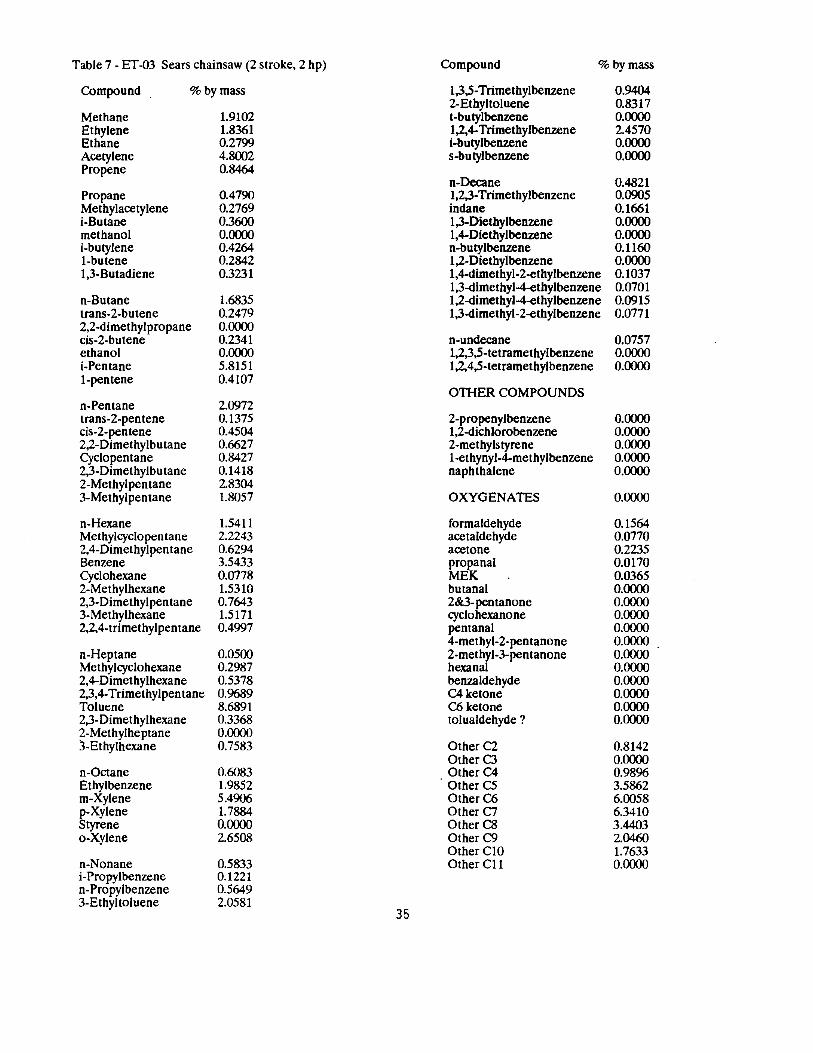
Table 7 - ET-03 Sears chainsaw (2 stroke, 2 hp) Compound % by mass
Compound %by mass 1,3,5-Trimethylbenzene 0.9404 2-Ethyltoluene 0.8317
Methane 1.9102 t-butylbenzene 0.0000 Ethylene 1.8361 1,2,4-Trimethylbenzene 2.4570 Ethane 0.2799 i-butylbenzene 0.0000 Acetylene 4.8002 s-butylbenzene 0.0000 Propene 0.8464
n-Decane 0.4821 Propane 0.4790 1,2,3-Trimethylbenzene 0.0905 Methylacetylene 0.2769 indane 0.1661 i-Butane 0.3600 1,3-Diethylbenzene 0.0000 methanol i-butylene
0.0000 0.4264
1,4-Diethylbenzene n-butylbenzene
0.0000 0.ll(i()
I-butene 0.2842 1,2-Diethylbenzene 0.0000 1,3-Butadiene 0.3231 1,4-dimethyl-2-ethylbenzene 0.1037
1,3-dimethyl-4-ethylbenzene 0.0701 n-Butane 1.6835 1,2-dimethyl-4-ethylbenzene 0.0915 trans-2-butene 0.2479 1,3-dimethyl-2-ethylbenzene 0.0771 2,2-dimethylpropane cis-2-butene
0.0000 0.2341 n-undecane 0.0757
ethanol 0.0000 1,2,3,5-tetramethylbenzene 0.0000 i-Pentane 5.8151 1,2,4,5-tetramethylbenzene 0.0000 1-pentene 0.4107
OTHER COMPOUNDS n-Pentane 2.0972 trans-2-pentene 0.1375 2-propenylbenzene 0.0000 cis-2-pentene 0.4504 1,2-dichlorobenzene 0.0000 2,2-Dimethylbutane 0.6627 2-methylstyrene 0.0000 Cyclopentane 0.8427 l-ethynyl-4-methylbenzene 0.0000 2,3-Dimethylbutane 0.1418 naphthalene 0.0000 2-Methylpentane 2.8304 3-Methylpentane 1.8057 OXYGENATES 0.0000
n-Hexane l.54ll formaldehyde 0.1564 Methylcyclopen tane 2.2243 acetaldehyde 0.0770 2,4-Dimethylpentane 0.6294 acetone 0.2235 Benzene 3.5433 propanal 0.0170 Cyclohexane 0.0778 MEK 0.0365 2-Methylhexane 1.5310 butanal 0.0000 2,3-Dimethylpentane 0.7643 2&3-pentanone 0.0000 3-Methylhexane 1.5171 cyclohexanone 0.0000 2,2,4-trimethylpentane 0.4997 pentanal 0.0000
4-methyl-2-pentanone 0.0000 n-Heptane 0.0500 2-methyl-3-pentanone 0.0000 Methylcyclohexane 0.2987 hexanal 0.0000 2,4-Dimethylhexane 0.5378 ben1.aldehyde 0.0000 2,3,4-Trimethylpentane 0.9689 C4ketone 0.0000 Toluene 8.6891 C6 ketone 0.0000 2,3-Dimethylhexane 0.3368 tolualdehyde ? 0.0000 2-Methylheptane 0.0000 3-Ethylhexane 0.7583 Other C2 0.8142
OtherC3 0.0000 n-Octane 0.(i()83 Other C4 0.98% Ethylbenzene 1.9852 Other CS 3.5862 m-Xylene 5.4906 OtherC6 6.0058 p-Xylene 1.7884 OtherC7 6.3410 Styrene 0.0000 Other C8 3.4403 o-Xylene 2.6508 OtherC9 2.04(i()
OtherCIO 1.7633 n-Nonane 0.5833 OtherCll 0.0000 i-Propylbenzene 0.1221 n-Propylbenzene 0.5649 3-Ethyltoluene 2.0581
35

Table 8- ET-04 Snapper trimmer (2 stroke, 2 hp) Compound % by mass
Compound % by mass
Methane 3.7875 Ethylene 1.2119 Ethane 0.2587 Acetylene 1.3383 Propene 2.1288
Propane 0.1828 Methylacetylene 0.1565 i-Butane 0.2886 methanol 0.0000 i-butylene 0.6252 I-butene 0.4957 1,3-Butadiene 0.4073
n-Butane 1.1256 trans-2-butene 0.2531 2,2-dimethylpropane 0.0000 cis-2-butene 0.2859 ethanol 0.0698 i-Pentane 5.5386 1-pentene 0.3667
n-Pentane 1.9171 trans-2-pentene 0.6899 cis-2-pen tene 0.9339 2,2-Dimethylbutane 0.1508 Cyclopentane 0.8071 2,3-Dimethylbutane 0.1030 2-Methylpentane 3.2084 3-Methylpentane 2.0314
n-Hexane 1.5095 Methylcyclopen tane 2.4509 2,4-Dimethylpentane 0.5815 Benzene 3.8729 Cyclohexane 0.0873 2-Methylhexane 1.7533 2,3-Dimethylpentane 0.6815 3-Methylhexane 1.7478 2,2,4-trimethylpentane 1.9523
n-Heptane 1.0934 Methylcyclohexane 0.3363 2,4-Dimethylhexane 0.6127 2,3,4-Trimethylpentane 0.9277 Toluene 10.5065 2,3-Dimethylhexane 0.3438 2-Methylheptane 0.8318 3-Ethylhexane 0.8321
n-Octane 0.6079 Ethylbenzene 1.7740 m-Xylene 6.3193 p-Xylene 1.9941 Styrene 0.3001 o-Xylene 2.8678
n-Nonane 0.4612 i-Propylbenzene 0.1377 n-Propylbenzene 0.5441 3-Ethyltoluene 1.8878
1,3,5-Trimethylbenzene 0.8536 2-Ethyltoluene 0.6916 t-butylbenzene 0.0000 1,2,4-Trimethylbenzene 1.6593 i-butylbenzene 0.0491 s-butylbenzene 0.0652
n-Decane 0.2745 1,2,3-Trimethylbenzene 0.2315 indane 0.0000 1,3-Diethylbenzene 0.0000 1,4-Diethylbenzene 0.0000 n-butylbenzene 0.0460 1,2-Diethylbenzene 0.0000 1,4-dimethyl-2-ethylbenzene 0.0559 1,3-dimethyl-4-ethylbenzene 0.0000 1,2-dimethyl-4-ethylbenzene 0.0557 · 1,3-dimethyl-2-ethylbenzene 0.0000
n-undecane 0.0000 1,2,3,5-tetramethylbenzene 0.0000 1,2,4,5-tetramethylbenzene 0.0000
OTI-IER COMPOUNDS
2-propenylbenzene 0.0000 1,2-dichlorobenzene 0.0000 2-methylstyrene 0.0000 1-ethynyl-4-methylbenzene 0.0000 naphthalene 0.0000
OXYGENATES 0.0000
formaldehyde 0.0101 acetaldehyde 0.0279 acetone 0.0184 propanal 0.0069 MEK 0.0129 butanal 0.0000 2&3-pentanone 0.0000 cyclohexanone 0.0006 pentanal 0.0003 4-methyl-2-pentanone 0.0255 2-methyl-3-pentanone 0.0009 hexanal 0.0123 beni.aldehyde 0.0111 C4 ketone 0.0111 C6 ketone 0.0000 tolualdehyde ? 0.0000
Other C2 0.4122 Other C3 0.0000 Other C4 1.0184 Other CS 2.6397 Other C6 5.4865 Other C7 5.0325 OlherC8 3.3566 Other C9 1.9003 Other ClO 0.6552 Other Cll 0.0000
36

Table 9- ET-05 Sears lawnmower (3 hp) Compound %by mass
Compound % by mass 1,3,5-Trimethylbenzene 2-Ethylloluene
0.810') 0.6858
Methane 2.2788 t-butylbenz.ene 0.0000 Ethylene Ethane
8.2577 0.4964
1,2,4-Trimethylbenzene i-butylbenzene
2.8694 0.0000
Acetylene 17.7112 s-butylbenz.ene 0.0000 Propene 3.3263
n-Decane 0.0000 Propane Methylacetylene i-Butane
0.5560 1.2840 0.2207
1,2,3-Trimethylbenzene indane 1,3-Diethylbenz.ene
0.5780 0.0000 0.2122
methanol i-butylene I-butene
0.1379 1.6062 0.9238
1,4-Diethylbenzene n-butylbenz.ene 1,2-Diethylbenzene
0.1966 0.0000 0.0000
1,3-Butadiene 1.5316 1,4-dimethyl-2-ethylbenz.ene 0.3271 1,3-dimethyl-4-ethylbenz.ene 0.0000
n-Butane 0.7251 1,2-dimetliyl-4-ethylbenzene 0.0000 trans-2-butene 0.2102 1,3-dimethyl-2-ethylbenzene 0.0000 2,2-dimethylpropane cis-2-butene
0.0000 0.1576 n-undecane 0.0000
ethanol 0.0525 1,2,3,5-tetramethylbenzene 0.0000 i-Pentane 1.4929 1,2,4,5-tetramethylbenzene 0.0000 1-pentene 0.0000
OTHER COMPOUNDS n-Pentane 1.1221 trans-2-pentene cis-2-pentene 2,2-Dimethylbutane Cyclopentane 2,3-Dimethylbutane
0.2197 0.2496 0.1248 0.0000 0.1741
2-propenylbenzene 1,2-dichlorobenzene 2-methylstyrene 1-ethynyl-4-methylbenzene naphthalene
0.0000 0.0000 0.0000 0.0000 0.0000
2-Methylpentane 3-Methylpentane
0.7980 0.5195 OXYGENATES 0.0000
n-Hexane 0.8581 formaldehyde 3.1622 Methylcyclopentane 2,4-Dimethylpentane Benzene Cyclohexane 2-Methylhexane 2,3-Dimethylpentane 3-Methylhexane 2,2,4-trimethylpentane
0.5773 0.1051 5.2688 0.0000 0.1576 0.0000 0.4407 0.3714
acetaldehyde acetone propanal MEK butanal 2&3-pen tanone cyclohexanone pentanal
0.1441 0.1129 0.0289 0.0000 0.0000 0.0000 0.0000 0.0000
4-methyl-2-pentanone 0.0000 n-Heptane Methylcyclohexane 2,4-Dimethylhexane 2,3,4-Trimethylpentane Toluene
0.4880 0.2844 0.1379 0.1901 5.8380
2-methyl-3-pentanone hexanal benzaldehyde C4 ketone C6 ketone
0.1009 0.0867 0.0153 0.0000 0.0000
2,3-Dimethylhexane 0.0000 tolualdehyde ? 0.0000 2-Methylheptane 0.3018 3-Ethylhexane 0.0000 Other C2 6.2977
OtherC3 1.0'J85 n-Octane 0.3668 Other C4 1.4591 Ethylbenzene m-Xylene p-Xylene Styrene
1.5775 4.3566 0.0000 0.5080
Other C5 Other C6 Other C7 Other CS
2.3224 1.3087 0.6535 0.9609
o-Xylene 1.9600 Other C9 Other ClO
2.2791 3.0117
n-Nonane 1.0643 Other CU 0.0000 i-Propylbenzene 0.0000 n-Propylbenzene 0.4554 3-Ethyltoluene 1.7925
37
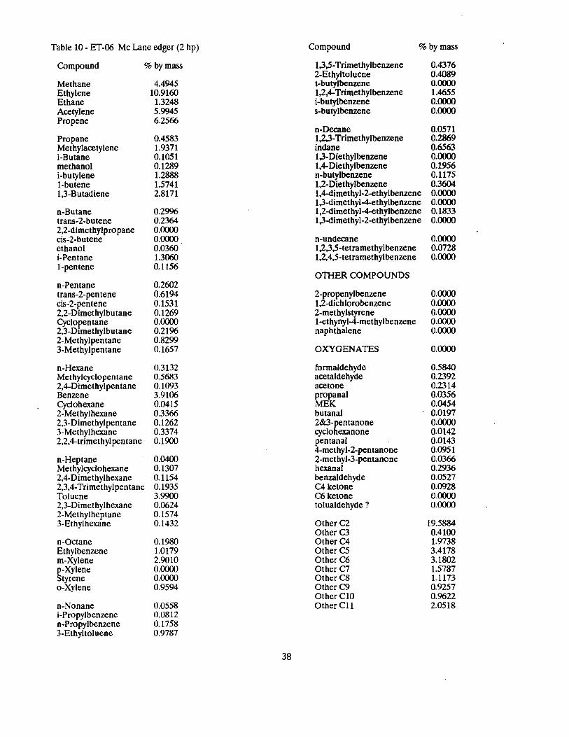
Table 10 - ET-06 Mc Lane edger (2 hp) Compound %by mass
Compound % by mass
Methane 4.4945 Ethylene 10.9160 Ethane 1.3248 Acetylene 5.9945 Propene 6.2566
Propane 0.4583 Methylacetylene 1.9371 i-Butane 0.1051 methanol 0.1289 i-butylene 1.2888 1-butene 1.5741 1,3-B utadiene 2.8171
n-Butane 0.2996 trans-2-butene 0.2364 2,2-dimethylpropane 0.0000 cis-2-butene 0.0000 ethanol 0.0360 i-Pentane 1.3060 1-pentene 0.1156
n-Pentane 0.2602 trans-2-pentene 0.6194 cis-2-pentene 0.1531 2,2-Dimethylbutane 0.1269 Cyclopentane 0.0000 2,3-Dimethylbutane 0.2196 2-Methylpentane 0.8299 3-Methylpentane 0.1657
n-Hexane 0.3132 Methylcyclopentane 0.5683 2,4-Dimethylpentane 0.1093 Benzene 3.9106 Cyclohexane 0.0415 2-Methylhexane 0.3366 2,3-Dimethylpentane 0.1262 3-Methylhexane 0.3374 2,2,4-trimethylpentane 0.1900
n-Heptane 0.0400 Methylcyclohexane 0.1307 2,4-Dimethylhexane 0.1154 2,3,4-Trimethylpentane 0.1935 Toluene 3.9900 2,3-Dimethylhexane 0.0624 2-Methylheptane 0.1574 3-Ethylhexane 0.1432
n-Octane 0.1980 Ethylbenzene 1.0179 m-Xylene 2.9010 p-Xylene 0.0000 Styrene 0.0000 o-Xylene 0.9594
n-Nonane 0.0558 i-Propylbenzene 0.0812 n-Propylbenzene 0.1758 3-Ethyltoluene 0.9787
1,3,5-Trimethylbenzene 2-Ethyltoluene t-butylbenzene 1,2,4-Trimethylbenzene i-butylbenzene s-butylbenzene
n-Decane 1,2,3-Trimethylbenzene indane 1,3-Diethylbenzene 1,4-Diethylbenzene n-butylbenzene 1,2-Diethylbenzene 1,4-dimethyl-2-ethylbenzene 1,3-dimethyl-4-ethylbenzene 1,2-dimethyl-4-ethylbenzene 1,3-dimethyl-2-ethylbenzene
n-undecane 1,2,3,5-tetramethylbenzene 1,2,4,5-tetramethylbenzene
OTHER COMPOUNDS
2-propenylbenzene 1,2-dichlorobenzene 2-methylstyrene l-ethynyl-4-methylbenzene naphthalene
OXYGENATES
formaldehyde acetaldehyde acetone propanal MEK butanal 2&3-pentanone cyclohexanone pentanal 4-methyl-2-pentanone 2-methyl-3-pentanone hexanal benzaldehyde C4 ketone C6 ketone tolualdehyde ?
Other C2 Other C3 OtherC4 Other CS Other C6 OtherC7 Other C8 OtherC9 Other ClO OtherCll
38
0.4376 0.4089 0.0000 1.4655 0.0000 0.0000
0.0571 0.2869 0.6563 0.0000 0.1956 0.1175 0.3604 0.0000 0.0000 0.1833 0.0000
0.0000 0.0728 0.0000
0.0000 0.0000 0.0000 0.0000 0.0000
0.0000
0.5840 0.2392 0.2314 0.0356 0.0454 0.0197 0.0000 0.0142 0.0143 0.0951 0.0366 0.2936 0.0527 0.0928 0.0000 0.0000
19.5884 0.4100 1.9738 3.4178 3.1802 1.5787 1.1173 0.9257 0.9622 2.0518

Table 11- ET-08 Husqvarna chainsaw (10 hp) Compound % by mass
Compound % by mass
Methane 9.1070 Ethylene 2.6137 Ethane 0.2586 Acetylene 2.8315 Propene 0.6513
Propane 0.6787 Methylacetylene 0.2062 i-Butane 0.1054 methanol 0.0827 i-butylene 0.0767 1-butene 1.0669 1,3-Butadiene 0.4649
n-Butane 0.4527 trans-2-butene 0.1791 2,2-dimethylpropane 0.0000 cis-2~butene 0.1346 ethanol 0.0230 i-Pentane 3.7059 1-pentene 0.2868
n-Pentane 1.2417 trans-2-pentene 0.2246 cis-2-pentene 0.2545 2,2-Dimethylbu tane 0.1650 Cyclopentane 0.2488 2,3-Dimethylbutane 0.6363 2-Methylpentane 2.3272 3-Methylpentane 1.4945
n-Hexane 0.9316 Methylcyclopentane 1.8561 2,4-Dimethylpentane 0.6006 Benzene 3.3129 Cyclohexane 0.2510 2-Methylhexane 1.3255 2,3-Dimethylpentane 0.5655 3-Methylhexane 1.2692 2,2,4-trimethylpentane 2.2062
n-Heptane 0.8188 Methylcyclohexane 0.8004 2,4-Dimethylhexane 0.5749 2,3,4-Trimethylpentane 1.0508 Toluene 8.4391 2,3-Dimethylhexane 0.3056 2-Methylheptane 0.6016 3-Ethylhexane 0.8207
n-Octane 0.3928 Ethylbenzene 2.0789 m-Xylene 0.0054 p-Xylene 1.8180 Styrene 0.0000 o-Xylene 5.3845
n-Nonane 0.3672 i-Propylbenzene 0.3648 n-Propylbenzene 0.6014 3-Ethyltoluene 2.4765
1,3,5-Trimethylbenzene 1.1240 2-Ethyltoluene 1.0125 t-butylbenzene 0.0000 1,2,4-Trimethylbenzene 3.4335 i-butylbenzene 0.0854 s-butylbenzene 0.1037
n-Decane 0.2819 1,2,3-Trimethylbenzene 0.7524 indane 0.2080 1,3-Diethylbenzene 0.0000 1,4-Diethylbenzene 0.6818 n-butylbenzene 0.0000 1,2-Diethylbenzene 0.8143 1,4-dimethyl-2-ethylbenzene 0.0000 1,3-dimethyl-4-ethylbenzene 0.0000 1,2-dimethyl-4-ethylbenzene 0.3934 1,3-dimethyl-2-ethylbenzene 0.0000
n-undecane 0.0000 1,2,3,5-tetramethylbenzene 0.0000 1,2,4,5-tetramethylbenzene 0.0000
OTHER COMPOUNDS
2-propenylbenzene 0.0000 1,2-dichlorobenzene 0.0000 2-methylstyrene 0.0000 1-ethynyl-4-methylbenzene 0.0000 naphthalene 0.0000
OXYGENATES 0.0000
formaldehyde 0.5983 acetaldehyde 0.2762 acetone 0.5461 propanal 0.0623 MEK 0.1428 butanal 0.0000 2&3-pentanone 0.0000 cyclohexanone 0.0000 pentanal 0.0000 4-methyl-2-pentanone 0.1436 2-methyl-3-pentanone 0.0812 hexanal 0.0000 benzaldehyde 0.0526 C4 ketone 0.0855 C6 ketone 0.0000 tolualdehyde ? 0.0000
OtherC2 1.2841 OtherC3 0.0486 OtherC4 1.2908 Other C5 2.2720 OtherC6 4.9000 Other C7 2.8654 Other C8 2.6308 Other C9 2.1370 Other ClO 2.8891 OtherCll 0.0646
39
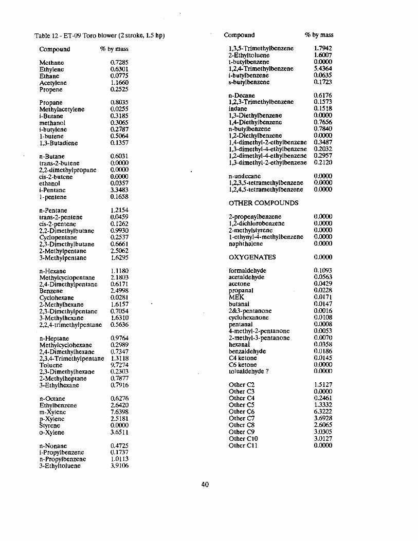
Table 12 - ET-09 Toro blower (2 stroke, 1.5 hp) Compound % by mass
Compound % by mass
Methane 0.7285 Ethylene 0.6301 Ethane 0.0775 Acetylene 1.1660 Propene 0.2525
Propane 0.8035 Methylacetylene 0.0255 i-Butane 0.3185 methanol 0.3065 i-butylene 0.2787 I-butene 0.5064 1,3-Butadiene 0.1357
n-Butane 0.6031 trans-2-butene 0.0000 2,2-dimethylpropane 0.0000 cis-2-butene 0.0000 ethanol 0.0357 i-Pentane 3.3483 1-pentene 0.1658
n-Pentane 1.2154 trans-2-pentene 0.0459 cis-2-pentene 0.1262 2,2-Dimethylbutane 0.9930 Cyclopentane 0.2537 2,3-Dimethylbutane 0.6661 2-Methylpentane 2.5062 3-Methylpentane 1.6295
n-Hexane 1.1180 Methylcyclopentane 2.1803 2,4-Dimethylpen tane 0.6171 Benzene 2.4998 Cyclohexane 0.0281 2-Methylhexane 1.6157 2,3-Dimethylpentane 0.7054 3-Methylhexane 1.6310 2,2,4-trimethylpentane 0.5636
n-Heptane 0,9764 Methylcyclohexane 0.2989 2,4-Dimethylhexane 0.7347 2,3,4-Trimethylpentane 1.3118 Toluene 9.7274 2,3-Dimethylhexane 0.2303 2-Methylheptane 0.7877 3-Ethylhexane 0.7916
n-Octane 0.6276 Ethylbenzene 2.6420 m-Xytene 7.6398 p-Xylene 2.5181 Styrene 0.0000 o-Xylene 3.6511
n-Nonane 0.4725 i-Propylbenzene 0.1737 n -Propylbenzene 1.0113 3-Ethyltoluene 3.9106
1,3,5-Trimethylbenzene 1.7942 2-Ethyltoluene 1.6007 t-butylbenzene 0.0000 1,2,4-Trimethylbenzene 5.4364 i-butylbenzene 0.0635 s-butylbenzene 0.1723
n-Decane 0.6176 1,2,3-Trimethylbenzene 0.1573 indane 0.1518 1,3-Diethylbenzene 0.0000 1,4-Diethylbenzene 0.7656 n-butylbenzene 0.7840 1,2-Diethylbenzene 0.0000 1,4-dimethyl-2-ethylbenzene 0.3487 1,3-dimethyl-4-ethylbenzene 0.2032 1,2-dimethyl-4-ethylbenzene 0.2957 1,3-dimethyl-2-ethylbenzene 0.2120
n-undecane 0.0000 1,2,3,5-tetramethylbenzene 0.0000 1,2,4,5-tetramethylbenzene 0.0000
OTHER COMPOUNDS
2-propenylbenzene 0.0000 1,2-dichlorobenzene 0.0000 2-methylstyrene 0.0000 1-ethynyl-4-methylbenzene 0.0000 naphthalene 0.0000
OXYGENATES 0.0000
formaldehyde 0.1093 acetaldehyde 0.0563 acetone 0.0429 propanal 0.0228 MEK 0.0171 butanal 0.0147 2&3-pentanone 0.0016 cyclohexanone 0.0108 pentanal 0.0008 4-methyl-2-pentanone 0.0053 2-methyl-3-pentanone 0.0070 hexanal 0.0358 benzaldehyde 0.0186 C4 ketone 0.0145 C6 ketone 0.0000 tolualdehyde ? 0.0000
Other C2 1.5127 Other C3 0.0000 Other C4 0.2461 Other CS 1.3332 OtherC6 6.3222 Other C7 3.6928 Other C8 2.6065 Other C9 3.0305 OtherClO 3.0127 Other Cll 0.0000
40
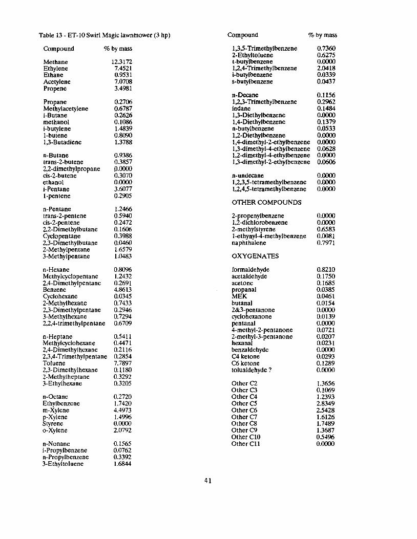
Table 13 - ET-10 Swirl Magic lawnmower (3 hp) Compound %by mass
Compound % by mass
Methane 12.3172 Ethylene 7.4521 Ethane 0.9531 Acetylene 7.0708 Propene 3.4981
Propane 0.2706 Methylacetylene 0.6787 i-Butane 0.2626 methanol 0.1086 i-butylene 1.4839 I-butene 0.8090 1,3-Butadiene 1.3788
n-Butane 0.9386 trans-2-butene 0.3857 2,2-dimethylpropane 0.0000 cis-2-butene 0.3070 ethanol 0.0000 i-Pentane 3.6077 1-pentene 0.2905
n-Pentane 1.2466 trans-2-pentene 0.5940 cis-2-pentene 0.2472 2,2-Dimethylbutane 0.1606 Cyclopentane 0.3988 2,3-Dimethylbutane 0.0460 2-Methylpentane 1.6579 3-Methylpentane 1.0483
n-Hexane 0.8096 Methylcyclopentane 1.2432 2,4-Dimethylpentane 0.2691 Benzene 4.8613 Cyclohexane 0.0345 2-Methylhexane 0.7433 2,3-Dimethylpentane 0.2946 3-Methylhexane 0.7294 2,2,4-trimethylpentane 0.6709
n-Heptane 0.5411 Methylcyclohexane 0.4471 2,4-Dimethylhexane 0.2116 2,3,4-Trimethylpentane 0.2854 Toluene 7.7897 2,3-Dime thylhexane o.uso 2-Methylheptane 0.3292 3-Ethylhexane 0.3205
n-Octane 0.2720 Ethylbenzene 1.7420 m-Xylene 4.4973 p-Xylene 1.4996 Styrene 0.0000 o-Xylene 2.0792
n-Nonane 0.1565 i-Propylbenzene 0.0762 n-Propylbenzene 0.3392 3-Ethyltoluene 1.6844
1,3,5-Trimethylbenzene 0.7360 2-Ethyltoluene 0.6275 t-butylbenzene 0.0000 1,2,4-Trimethylbenzene 2.0418 i-butylbenzene 0.0339 s-butylbenzene 0.0437
n-Decane 0.1156 1,2,3-Trimethylbenzene 0.2962 indane 0.1484 1,3-Diethylbenzene 0.0000 1,4-Diethylbenzene 0.1379 n-butylbenzene 0.0533 1,2-Diethylbenzene 0.0000 1,4-dimethyl-2-ethylbenzene 0.0000 1,3-dimethyl-4-ethylbenzene 0.0628 1,2-dimethyl-4-ethylbenzene 0.0000 1,3-dimethyl-2-ethylbenzene 0.0606
n-undecane 0.0000 1,2,3,5-tetramethylbenzene 0.0000 1,2,4,5-tetramethylbenzene 0.0000
OTHER COMPOUNDS
2-propenylbenzene 0.0000 1,2-dichlorobenzene 0.0000 2-methylstyrene 0.6583 1-ethynyl-4-methylbenzene 0.0081 naphthalene 0.7971
OXYGENATES
formaldehyde 0.8210 acetaldehyde 0.1750 acetone 0.1685 propanal 0.0385 MEK 0.0461 butanal 0.0154 2&3-pentanone 0.0000 cyclohexanone 0.0139 pentanal 0.0000 4-methyl-2-pentanone 0.0721 2-methyl-3-pentanone 0.0207 hexanal 0.0231 benzaldehyde 0.0000 C4 ketone 0.0293 C6 ketone 0.1289 tolualdehyde ? 0.0000
OtherC2 1.3656 Other C3 0.1069 Other C4 1.2393 Other CS 2.8349 OtherC6 2.5428 Other C7 1.6126 Other C8 1.7489 OtherC9 1.3687 OtherClO 0.5496 Other Cl! 0.0000
41

Table 1'4 - ET-11 Swirl Magic lawnmower ( 3 hp) Compound %by mass
Compound % by mass
Methane 8.4401 Ethylene 7.3841 Ethane 0.9230 Acetylene 9.4804 Propene 3.7195
Propane 0.1459 Methylacetylene 0.4185 i-Butane 0.2562 methanol 0.0809 i-butylene 1.3373 I-butene 0.7917 1,3-Butadiene 1.2842
n-Butane 0.8983 trans-2-butene 0.3641
. 2,2-dimethylpropane 0.0000 cis-2-butene 0.2881 ethanol 0.0534 i-Pentane 3.4600 1-pentene 0.2781
n-Pentane 1.1572 trans-2-pentene 0.5304 cis-2-pentene 0.2357 2,2-Dimethylbutane 0.6045 Cyclopentane 0.1985 2,3-Dimethylbutane 0.3842 2-Methylpentane 1.5791 3-Methylpentane 0.6810
n-Hexane 0.7480 Methylcyclopentane 1.1765 2,4-Dimethylpentane 0.2616 Benzene 4.1764 Cyclohexane 0.0337 2-Methylhexane 0.7122 2,3,Dimethylpentane 0.2901 3-Methylhexane 0.6973 2,2,4-trimethylpentane 0.6621
n-Heptane 0.0412 Methylcyclohexane 0.4283 2,4-Dimethylhexane 0.2046 2,3,4-Trimethylpen tane 0.2839 Toluene 6.7268 2,3-Dimethylhexane 0.1063 2-Methylheptane 0.3130 3-Ethylhexane 0.3066
n-Octane 0.2526 Ethylbenzene 1.5863 m-Xylene 4.0986 p-Xylene 1.3619 Styrene 0.5943 o-Xylene 1.9286
n-Nonane 0.1366 i-Propylbenzene 0.0750 n-Propylbenzene 0.3598 3-Ethyltoluene 1.8133
1,3,5-Trimethylbenzene 0.8014 2-Ethyltoluene 0.8961 t-butylbenzene 0.0000 1,2,4-Trimethylbenzene 29129 i-butylbeni.ene 0.0444 s-butylbenzene 0.0553
n-Decane 0.1350 1,2,3-Trimethylbenzene 0.5743 indane 0.5651 1,3-Diethylbenzene 0.0000 1,4-Diethylbeni.ene 0.4122 n-butylbenzene 0.6659 1,2-Diethylbenzene 0.0000 1,4-dimethyl-2-ethylbeni.ene 0.3438 1,3-dimethyl-4-ethylbenzene 0.3455 1,2-dimethyl-4-ethylbenzene 0.4309 1,3-dimethyl-2-ethylbeni.ene 0.1788
n-undecane 0.0943 1,2,3,5-tetramethylbenzene 0.0000 1,2,4,5-tetramethylbenzene 0.1817
O11-IER COMPOUNDS
2-propenylbenzene 0.0000 1,2-dichlorobenzene 0.0000 2-methylstyrene 0.0000 1-ethynyl-4-methylbenzene 0.0000 naphthalene 0.0000
OXYGENATES
formaldehyde 0.6614 acetaldehyde 0.1408 acetone 0.1436 propanal 0.0283 MEK 0.0368 butanal 0.0102 2&3-pentanone 0.0000 cyclohexanone 0.0114 pentanal 0.0000 4-methyl-2-pentanone 0.0666 2-methyl-3-pen tanone 0.0154 hexanal 0.0201 benzaldehyde 0.0000 C4 ketone 0.0269 C6 ketone 0.1137 tolualdehyde ? 0.0000
OtherC2 2.9143 OtherC3 0.0906 OtherC4 1.2379 Other C5 2.3149 Other C6 2.6658 Other C7 2.1598 Other C8 1.1480 Other C9 1.6944 OtherClO 1.3004 OtherCll 0.2114
42
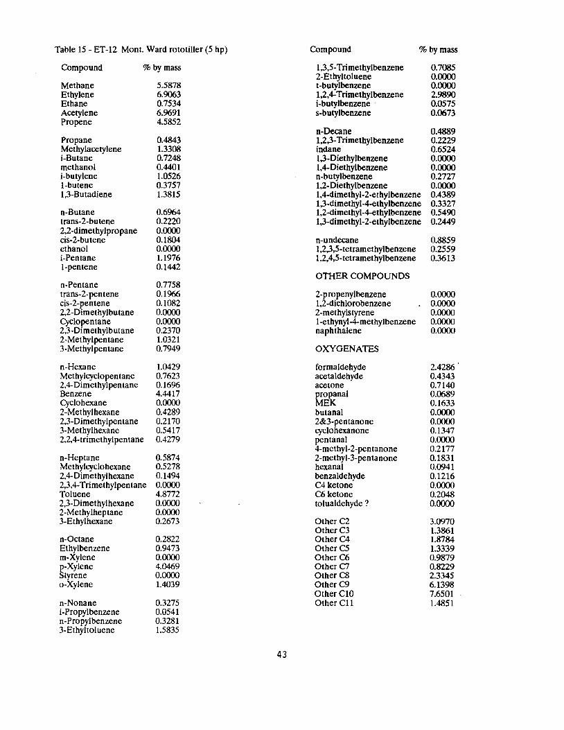
Table 15 - ET-12 Mont. Ward rototiller (5 hp) Compound % by mass
Compound %by mass
Methane 5.5878 Ethylene 6.9063 Ethane 0.7534 Acetylene 6.9691 Propene 4.5852
Propane 0.4843 Methylacetylene 1.3308 i-Butane 0.7248 methanol 0.4401 i-butylene 1.0526 I-butene 0.3757 1,3-Butadiene 1.3815
n-Butane 0.6964 trans-2-butene 0.2220 2,2-dimethylpropane 0.0000 cis-2-butene 0.1804 ethanol 0.0000 i-Pentane 1.1976 1-pentene 0.1442
n-Pentane 0.7758 trans-2-pentene 0.1966 cis-2-pentene 0.1082 2,2-Dimethylbutane 0.0000 Cyclopentane 0.0000 2,3-Dimethylbutane 0.2370 2-Methylpentane 1.0321 3-Methylpentane 0.7949
n-Hexane 1.0429 Methylcyclopentane 0.7623 2,4-Dimethylpentane 0.1696 Benzene 4.4417 Cyclohexane 0.0000 2-Methylhexane 0.4289 2,3-Dimethylpentane 0.2170 3-Methylhexane 0.5417 2,2,4-trimethylpentane 0.4279
n-Heptane 0.5874 Methylcyclohexane 0.5278 2,4-Dimethylhexane 0.1494 2,3,4-Trimethylpentane 0.0000 Toluene 4.8772 2,3-Dimethylhexane 0.0000 2-Methylheptane 0.0000 3-Ethylhexane 0.2673
n-Octane 0.2822 Ethylbenzene 0.9473 m-Xylene 0.0000 p-Xylene 4.0469 Styrene 0.0000 o-Xylene 1.4039
n-Nonane 0.3275 i-Propylbenzene 0.0541 n-Propylbenzene 0.3281 3-Ethyltoluene 1.5835
1,3,5-Trimethylbenzene 0.7085 2-Ethyltoluene 0.0000 t-butylbenzene 0.0000 1,2,4-Trimethylbenzene 2.9890 i-butylbenzene 0.0575 s-butylbenzene 0.0673
n-Decane 0.4889 1,2,3-Trimethylbenzene 0.2229 indane 0.6524 1,3-Diethylbenzene 0.0000 1,4-Diethylbenzene 0.0000 n-butylbenzene 0.2727 1,2-Diethylbenzene 0.0000 1,4-dimethyl-2-ethylbenzene 0.4389 1,3-dimethyl-4-ethylbenzene 0.3327 l,2-dimethyl-4-ethylbenzene 0.5490 1,3-dimethyl-2-ethylbenzene 0.2449
n-undecane 0.8859 1,2,3,5-tetramethylbenzene 0.2559 1,2,4,5-tetramethylbenzene 0.3613
OTHER COMPOUNDS
2-propenylbenzene 0.0000 1,2-dichlorobenzene 0.0000 2-methylstyrene 0.0000 1-ethynyl-4-methylbenzene 0.0000 naphthalene 0.0000
OXYGENATES
formaldehyde 2.4286. acetaldehyde 0.4343 acetone 0.7140 propanal 0.0689 MEK 0.1633 butanal 0.0000 2&3-pentanone 0.0000 cyclohexanone 0.1347 pentanal 0.0000 4-methyl-2-pentanone 0.2177 2-methyl-3-pentanone 0.1831 hexanal 0.0941 benzaldehyde 0.1216 C4 ketone 0.0000 C6 ketone 0.2048 tolualdehyde ? 0.0000
Other C2 3.0970 OtherC3 1.3861 OtherC4 1.8784 Other C5 1.3339 Other C6 0.9879 Other C7 0.8229 Other C8 2.3345 OtherC9 6.1398 Other ClO 7.6501 Other Cll 1.4851
43
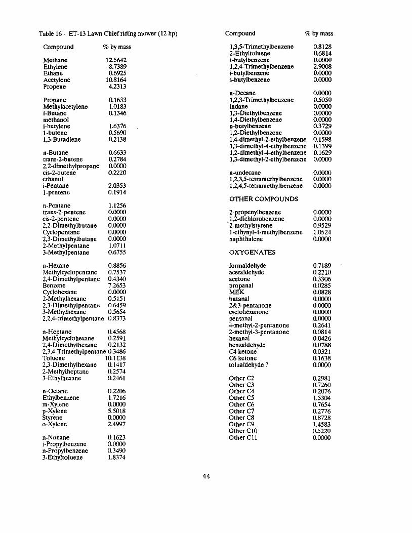
Table 16- ET-13 Lawn Chief riding mower (12 hp) Compound % by mass
Compound % by mass
Methane 12.5642 Ethylene 8.7389 Ethane 0.6925 Acetylene 10.8164 Propene 4.2313
Propane 0.1633 Methylacetylene 1.0183 i-Butane 0.1346 methanol i-butylene 1.6376 1-butene 0.5690 1,3-Butadiene 0.2138
n-Butane 0.6633 trans-2-butene 0.2784 2,2-dimethylpropane 0.0000 cis-2-butene 0.2220 ethanol i-Pentane 2.0353 1-pentene 0.1914
n-Pentane 1.1256 trans-2-pentene 0.0000 cis-2-pentene 0.0000 2,2-Dimethylbutane 0.0000 Cyclopentane 0.0000 2,3-Dimethylbutane 0.0000 2-Methylpentane 1.0711 3-Methylpentane 0.6755
n-Hexane 0.8856 Methylcyclopen tane 0.7537 2,4-Dimethylpentane 0.4340 Benzene 7.2653 Cyclohexane 0.0000 2-Methylhexane 0.5151 2,3-Dimethylpentane 0.6459 3-Methylhexane 0.5654 2,2,4-trimethylpentane 0.8373
n-Heptane 0.4568 Methylcyclohexane 0.2591 2,4-Dimethylhexane 0.2132 2,3,4-Trimethylpentane 0.3486 Toluene 10.1138 2,3-Dimethylhexane 0.1417 2-Methylheptane 0.2574 3-Ethylhexane 0.2461
n-Octane 0.2206 Ethylbenzene 1.7216 m-Xylene 0.0000 p-Xylene 5.5018 Styrene 0.0000 o-Xylene 2.4997
n-Nonane 0.1623 i-Propylbenzene 0.0000 n-Propylbenzene 0.3490 3-Ethyltoluene 1.8374
1,3,5-Trimethylbenzene 2-Ethyltoluene t-butylbenzene 1,2,4-Trimethylbenzene i-butylbenzene s-butylbenzene
n-Decane 1,2,3-Trimethylbenzene indane 1,3-Diethylbenzene 1,4-Diethylbenzene n-butylbenzene 1,2-Diethylbenzene 1,4-dimethyl-2-ethylbenzene 1,3-dimethyl-4-ethylbenzene 1,2-dimethyl-4-ethylbenzene 1,3-dimethyl-2-ethylbenzene
n-undecane 1,2,3,5-tetramethylbenzene 1,2,4,5-tetramethylbenzene
OTHER COMPOUNDS
2-propenylbenzene 1,2-dichlorobenzene 2-methylstyrene l-ethynyl-4-methylbenzene naphthalene
OXYGENATES
formaldehyde acetaldehyde acetone propanal MEK butanal 2&3-pentanone cyclohexanone pentanal 4-methyl-2-pentanone 2-methyl-3-pentanone hexanal benzaldehyde C4 ketone C6 ketone tolualdehyde ?
Other C2 OtherC3 OtherC4 Other CS Other C6 Other C7 Other C8 Other C9 OtherClO OtherCll
0.8128 0.6814 0.0000 2.9008 0.0000 0.0000
0.0000 0.5050 0.0000 0.0000 0.0000 0.3729 0.0000 0.1598 0.1399 0.1629 0.0000
0.0000 0.0000 0.0000
0.0000 0.0000 0.9529 1.0524 0.0000
0.7189 0.2210 0.3306 0.0285 0.0828 0.0000 0.0000 0.0000 0.0000 0.2641 0.0814 0.0426 0.0788 0.0321 0.1638 0.0000
0.2981 0.7260 0.2076 1.5304 0.7654 0.2776 0.8728 1.4583 0.5220 0.0000
44
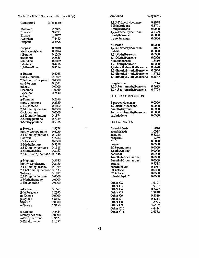
Table 17 - ET-15 Sears rototiller (gas, 8 hp) Compound % by mass
Compound % by mass
Methane 2.2885
1,3,5-Trimethylbenzene 2-Ethyltoluene t-butylbenzene
0.8978 0.8771 0.0000
Ethylene 9.8711 Ethane 1.5867
1,2,4-Trimethylbenzene i-butylbenzene
4.5399 0.0000
Acetylene 7.4453 s-butylbenzene 0.0000 Propene 2.3996
n-Decane 0.0000 Propane 0.3018 Methylacetylene 0.5994
1,2,3-Trimethylbenzene indane
1.1097 0.0000
i-Butane 0.1200 1,3-Diethylbenzene 0.0000 methanol 0.2555 i-butylene 0.6069
1,4-Diethylbenzene n-butylbenzene
0.0000 1.8419
I-butene 0.4216 1,2-Diethylbenzene 0.0000 1,3-Butadiene 0.8714 1,4-dimethyl-2-ethylbenzene 0.8678
1,3-dimethyl-4-ethylbenzene 0.6974 n-Butane 0.6088 1,2-dimethyl-4-ethylbenzene 1.1712 trans-2-butene 0.1409 1,3-dimethyl-2-ethylbenzene 0.4537 2,2-dimethylpropane 0.0000 cis-2-butene 0.1051 n-undecane 1.0216 ethanol 0.0000 1,2,3,5-tetramethylbenzene 0.5683 i-Pentane 1.6989 1,2,4,5-tetramethylbenzene 0.9704 1-pentene 0.2440 ethanol O11-IER COMPOUNDS n-Pentane 0.2656 trans-2-pentene 0.2530 2-propenylbenzene 0.0000 cis-2-pentene 0.1062 1,2-dichlorobenzene 0.0000 2,2-Dimethylbu tane 0.0000 Cyclopentane 0.0000 2,3-Dimethylbutane 0.1874
2-methylstyrene l-ethynyl-4-methylbenzene naphthalene
0.0000 0.0000 0.0000
2-Methylpentane 0.7759 3-Methylpentane 0.5076 OXYGENATES
n-Hexane 1.5278 formaldehyde 1.5810 Methylcyclopentane 0.6230 acetaldehyde 1.0038 2,4-Dimethylpentane 0.1280 acetone 0.8273 Benzene 5.2782 propanal 1.1289 Cyclohexane 0.0000 MEK 0.0000 2-Methylhexane 0.3359 butanal 0.0000 2,3-Dimethylpentane 0.1518 2&3-pentanone 0.0000 3-Methylhexane 0.3757 cyclohexanone 0.0000 2,2,4-trimethylpentane 0.1546 pentanal 0.0000
4-methyl-2-pentanone 0.0000 n-Heptane 0.3185 2-methyl-3-pentanone 0.0000 Methylcyclohexane 0.2436 hexanal 0.5588 2,4-Dimethylhexane 0.1079 benzaldehyde 0.4944 2,3,4-Trimethylpentane 0.1533 C4 ketone 0.0000 Toluene 6.1387 C6ketone 0.0000 2,3-Dimethylhexane 0.0000 tolualdehyde? 0.0000 2-Methylheptane 0.0000 3-Ethylhexane 0.0000 Other C2 1.6191
Other C3 1.9307 n-Octane 0.1661 OtherC4 0.7472 Ethylbenzene 1.2243 Other CS 1.9839 m-Xylene 0.0000 Other C6 0.8010 p-Xylene 5.8142 OtherC7 0.4214 Styrene 0.0000 Other C8 1.8993 o-Xylene 1.9150 Other C9 3.6157
OtherClO 4.6434 n-Nonane 0.2834 Other Cll 2.6582 i-Propylbenzene 0.0000 n-Propylbenzene 0.3627 3-Ethyltoluene 2.1057
45
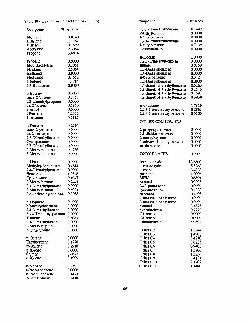
Table 18 - ET-17 Ford diesel tractor (130 hp) Compound % by mass
Compound % by mass 1,3,5-Trimethylbenzene 0.1442 2-Ethyltoluene 0.0000
Methane 0.8140 t-butylbenzene 0.0000 Ethylene Ethane
11.7762 0.1899
1,2,4-Trimethylbenzene i-butylbenzene
0.0000 0.7139
Acetylene 2.3064 s-butylbenzene 0.0000 Propene 3.6814
n-Decane 1.0099 Propane 0.0000 1,2,3-Trimethylbenzene 0.0000 Methylacetylene 0.2861 indane 0.8259 i-Butane 2.5084 1,3-Diethylbenzene 0.0000 methanol 0.0000 1,4-Diethylbenzene 0.0000 i-butylene 0.7552 n-butylbenzene 0.3727 1-butene 1.1784 1,2-Diethylbenzene 0.0000 1,3-Butadiene 0.0000 1,4-dimethyl-2-ethylbenzene 0.5263
1,3-dimethyl-4-ethylbenzene 0.2640 n-Butane 0.0000 1,2-dimethyl-4-ethylbenzene 0.4082 trans-2-butene 0.3517 1,3-dimethyl-2-ethylbenzene 0.3939 2,2-dimethylpropane 0.0000 cis-2-butene 0.1310 n-undecane 1.7610 ethanol 0.0000 1,2,3,5-tetramethylbenzene 0.2863 i-Pentane 1.2323 1,2,4,5-tetramethylbenzene 0.3500 1-pentene 0.5115
OTHER COMPOUNDS n-Pentane 0.2314 trans-2-pentene 0.0000 2-propenylbenzene 0.0000 cis-2-pente!le 0.0000 1,2-dichlorobenzene 0.0000 2,2-Dimethylbutane 0.0000 2-methylstyrene 0.0000 Cyclopentane 0.0000 l-ethynyl-4-methylbenzene 0.0000 2,3-Dimethylbutane 0.0000 naphthalene 0.0000 2-Methylpentane 0.9766 3-Methylpentane 0.0000 OXYGENATES 0.0000
n-Hexane 0.0000 formaldehyde 13.8609 Methylcyclopentane 0.4614 acetaldehyde 5.5769 2,4-Dimethylpentane 0.0000 acetone 3.4737 Benzene 1.0546 propanal 1.0996 Cyclohexane 0.1047 MEK 0.6891 2-Methylhexane 0.2441 butanal 0.9395 2,3-Dimethylpentane 0.0000 2&3-pentanone 0.0000 3-Methylhexane 0.6024 cyclohexanone 0.4923 2,2,4-trimethylpentane 0.3088 pentanal 0.4698
4-methyl-2-pentanone 0.0000 n-Heptane 0.0000 2-methyl-3-pentanone 0.0000 Methylcyclohexane 0.0000 hexanal 2.4875 2,4-Dimethylhexane 0.0000 benzaldehyde 0.7770 2,3,4-Trimethylpen tane 0.0000 C4 ketone 0.0000 Toluene 0.6061 C6 ketone 0.0000 2,3-Dimethylhexane 0.0000 tolualdehyde ? 5.9897 2-Methylheptane 0.0000 3-Ethylhexane 0.0000 Other C2 1.3744
Other C3 1.4903 n-Octane 0.0000 Other C4 3.4210 Ethylbenzene 0.1778 Other CS 3.6225 m-Xylene 0.2918 Other C6 0.9483 p-Xylene Styrene
0.0000 0.0877
Other C7 Other C8
1.3786 1.2236
o-Xylene 0.1999 Other C9 3.4121 OtherClO 7.1707
n-Nonane 0.2391 Other Cll 1.3480 i-Propylbenzene 0.0000 n-Propylbenzene 0.1473 3-Ethyltoluene 0.2418
46
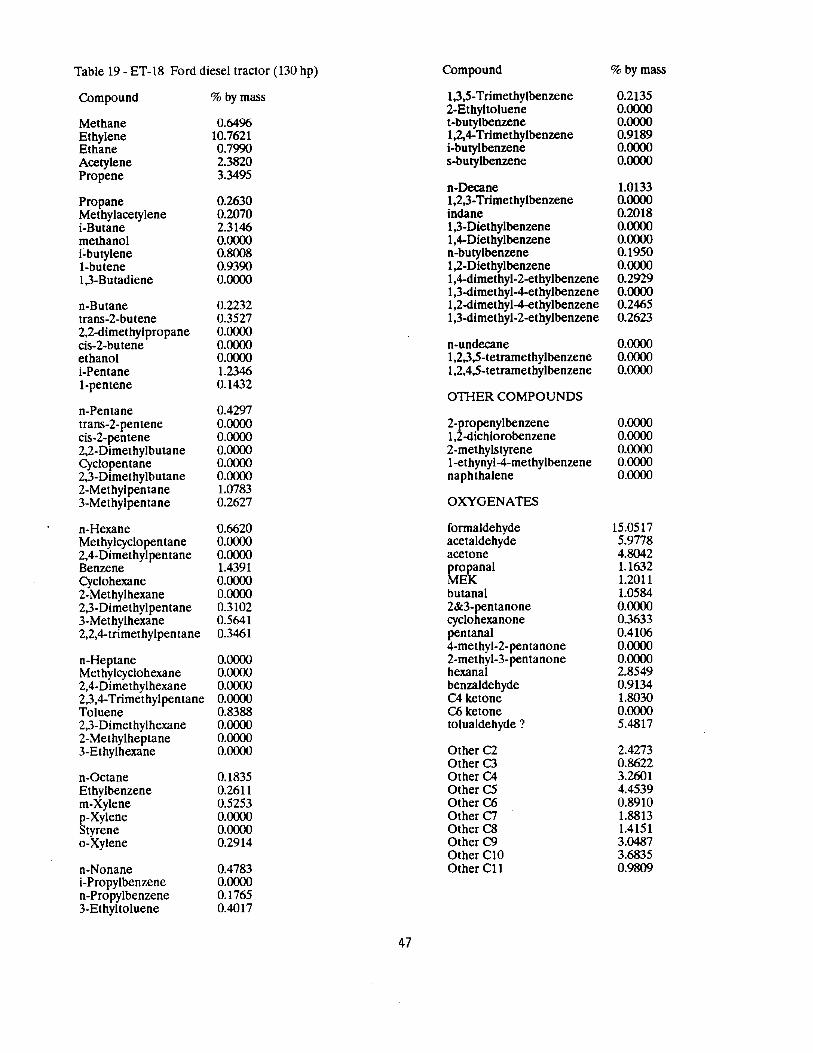
Table 19 - ET-18 Ford diesel tractor (130 hp) Compound % by mass
Compound
Methane Ethylene Ethane Acetylene Propene
Propane Methylacetylene i-Butane methanol i-butylene 1-butene 1,3-Butadiene
n-Butane trans-2-butene 2,2-dimethylpropane cis-2-butene ethanol i-Pentane 1-pentene
n-Pentane trans-2-pentene cis-2-pentene 2,2-Dimethylbutane Cyclopentane 2,3-Dimethylbutane 2-Methylpentane 3-Methylpentane
n-Hexane Methylcyclopentane 2,4-Dimethylpentane Benzene Cyclohexane 2-Methylhexane 2,3-Dimethylpentane 3-Methylhexane 2,2,4-trimethylpentane
n-Heptane Methylcyclohexane 2,4-Dimethylhexane 2,3,4-Trimethylpentane Toluene 2,3-Dimethylhexane 2-Methylheptane 3-Ethylhexane
n-Octane Ethylbenzene m-Xylene p-Xylene Styrene o-Xylene
n-Nonane i-Propylbenzene n-Propylbenzene 3-Ethyltoluene
% by mass
0.6496 10.7621 0.7990 2.3820 3.3495
0.2630 0.2070 2.3146 0.0000 0.8008 0.9390 0.0000
0.2232 0.3527 0.0000 0.0000 0.0000 1.2346 0.1432
0.4297 0.0000 0.0000 0.0000 0.0000 0.0000 1.0783 0.2627
0.6620 0.0000 0.0000 1.4391 0.0000 0.0000 0.3102 0.5641 0.3461
0.0000 0.0000 0.0000 0.0000 0.8388 0.0000 0.0000 0.0000
0.1835 0.2611 0.5253 0.0000 0.0000 0.2914
0.4783 0.0000 0.1765 0.4017
1,3,5-Trimethylbenzene 0.2135 2-Ethyltoluene 0.0000 t-butylbenzene 0.0000 1,2,4-Trimethylbenzene 0.9189 i-butylbenzene 0.0000 s-butylbenzene 0.0000
n-Decane 1.0133 1,2,3-Trimethylbenzene 0.0000 indane 0.2018 1,3-Diethylbenzene 0.0000 1,4-Diethylbenzene 0.0000 n-butylbenzene 0.1950 1,2-Diethylbenzene 0.0000 l,4-dimethyl-2-ethylbenzene 0.2929 l,3-dimethyl-4-ethylbenzene 0.0000 l,2-dimethyl-4-ethylbenzene 0.2465 1,3-dimethyl-2-ethylbenzene 0.2623
n-undecane 0.0000 1,2,3,5-tetramethylbenzene 0.0000 1,2,4,5-tetramethylbenzene 0.0000
OTHER COMPOUNDS
2-propenylbenzene 0.0000 1,2-dichlorobenzene 0.0000 2-methylstyrene 0.0000 l-ethynyl-4-methylbenzene 0.0000 naphthalene 0.0000
OXYGENATES
formaldehyde 15.0517 acetaldehyde 5.9778 acetone 4.8042 propanal 1.1632 MEK 1.2011 butanal 1.0584 2&3-pentanone 0.0000 cyclohexanone 0.3633 pentanal 0.4106 4-methyl-2-pentanone 0.0000 2-methyl-3-pentanone 0.0000 hexanal 2.8549 benzaldehyde 0.9134 C4 ketone 1.8030 C6 ketone 0.0000 tolualdehyde ? 5.4817
Other C2 2.4273 Other C3 0.8622 Other C4 3.2601 Other CS 4.4539 Other C6 0.8910 Other C7 1.8813 Other C8 1.4151 Other C9 3.0487 Other ClO 3.6835 Other CU 0.9809
47
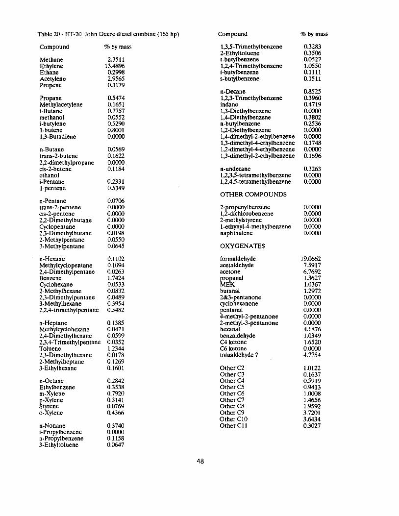
Table 20 - ET-20 John Deere diesel combine (165 hp) Compound %by mass
Compound
Methane Ethylene Ethane Acetylene Propene
Propane Methylacetylene i-Butane methanol i-butylene I-butene 1,3-Butadiene
n-Butane trans-2-butene 2,2-dimethylpropane cis-2-butene ethanol i-Pentane 1-pentene
n-Pentane trans-2-pentene cis-2-pentene 2,2-Dimethylbutane Cyclopentane 2,3-Dimethylbutane 2-Methylpentane 3-Methylpentane
n-Hexane Methylcyclopen tane 2,4-Dimethylpentane Benzene Cyclohexane 2-Methylhexane 2,3-Dimethylpentane 3-Methylhexane 2,2,4-trimethylpentane
n-Heptane Methylcyclohexane 2,4-Dimethylhexane 2,3,4-Trimethylpentane Toluene 2,3-Dimethylhexane 2-Methylheptane 3-Ethylhexane
n-Octane Ethylbenzene m-Xylene p-Xylene Styrene o-Xylene
n-Nonane i-Propylbenzene n-Propylbenzene 3-Ethyltoluene
%by mass
2.3511 13.4896 0.2998 2.9565 0.3179
0.5474 0.1651 0.7757 0.0552 0.5290 0.8001 0.0000
0.0569 0.1622 0.0000 0.1184
0.2331 0.5349
0.0706 0.0000 0.0000 0.0000 0.0000 0.0198 0.0550 0.0645
0.1102 0.1094 0.0263 1.7424 0.0533 0.0832 0.0489 0.3954 0.5482
0.1385 0.0471 0.0599 0.0352 1.2344 0.0178 0.1269 0.1601
0.2842 0.3538 0.7920 0.3141 0.0769 0.4366
0.3740 0.0000 0.1158 0.0647
1,3,5-Trimethylbenzene 0.3283 2-Ethyltoluene 0.3506 t-butylbenzene 0.0527 1,2,4-Trimethylbenzene 1.0550 i-butylbenzene 0.1111 s-butylbenzene 0.1511
n-Decane 0.8525 1,2,3-Trimethylbenzene 0.3960 indane 0.4719 1,3-Diethylbenzene 0.0000 1,4-Diethylbenzene 0.3802 n-butylbenzene 0.2536 1,2-Diethylbenzene 0.0000 1,4-dimethyl-2-ethyl benzene 0.0000 1,3-dimethyl-4-ethylbenzene 0.1748 1,2-dimethyl-4-ethylbenzene 0.0000 1,3-dimethyl-2-ethylbenzene 0.1696
n-undecane 0.3263 1,2,3,5-tetramethylbenzene 0.0000 1,2,4,5-tetramethylbenzene 0.0000
OTHER COMPOUNDS
2-propenylbenzene 0.0000 1,2-dichlorobenzene 0.0000 2-methylstyrene 0.0000 1-ethynyl-4-methylbenzene 0.0000 naphthalene 0.0000
OXYGENATES
formaldehyde 19.0662 acetaldehyde 7.5917 acetone 6.7692 propanal 1.3627 MEK 1.0367 butanal 1.2972 2&3-i::ntanone 0.0000 cyclo exanone 0.0000 pentanal 0.0000 4-methyl-2-pentanone 0.0000 2-methyl-3-pen tanone 0.0000 hexanal 4.1876 benzaldehyde 1.0349 C4 ketone 1.6520 C6 ketone 0.0000 tolualdehyde ? 4.7754
Other C2 1.0122 Other C3 0.1637 Other C4 0.5919 Other C5 0.9413 Other C6 1.0008 OtherC7 1.4656 Other C8 1.9592 Other C9 3.7201 Other ClO 3.6434 Other CU 0.3027
48
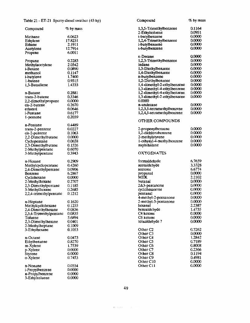
Table 21 - ET-21 Sperry diesel swather (43 hp) Compound % by mass
Compound
Methane Ethylene Ethane Acetylene Propene
Propane Methylacetylene i-Butane methanol i-butylene 1-butene 1,3-Butadiene
n-Butane trans-2-butene 2,2-dimethylpropane cis-2-butene ethanol i-Pentane 1-pentene
n-Pentane trans-2-pentene cis-2-pentene 2,2-Dimethylbutane Cyclopentane 2,3-Dimethylbutane 2-Methylpentane 3-Methylpentane
n-Hexane Methylcyclopentane 2,4-Dimethylpentane Benzene Cyclohexane 2-Methylhexane 2,3-Dimethylpentane 3-Methylhexane 2,2,4-trimethylpentane
n-Heptane Methylcyclohexane 2,4-Dimethylhexane 2,3,4-Trimethylpentane Toluene 2,3-Dimethylhexane 2-Methylheptane 3-Ethylhexane
n-Octane Ethylbenzene m-Xylene p-Xylene Styrene a-Xylene
n-Nonane i-Propylbenzene n-Propylbenzene 3-Ethyltoluene
% by mass
6.0623 17.8231 2.1911
12.7914 6.0011
0.2283 2.0342 0.0890 0.1147 1.7400 0.9315 1.4333
0.2881 0.3346 0.0000 0.2670 0.0646 0.6177 0.2039
0.4489 0.0227 0.1063 0.0000 0.0658 0.1526 0.6070 0.3943
0.2909 0.4260 0.0906 6.2867 0.0000 0.2707 0.1185 0.2685 0.1212
0.1620 0.1255 0.0836 0.0835 5.6894 0.0401 0.1009 0.1053
0.0473 0.8270 1.7539 0.0000 0.0000 0.7453
0.0554 0.0000 0.0000 0.0000
1,3,5-Trimethylbenzene 0.1164 2-Ethyltoluene 0.0951 t-butylbenzene 0.0000 1,2,4-Trimethylbenzene 0.0000 i-butylbenzene 0.0000 s-butylbenzene 0.0000
n-Decane 0.0000 1,2,3-Trimethylbenzene 0.0000 indane 0.0000 1,3-Diethylbenzene 0.0000 1,4-Diethylbenzene 0.0000 n-butylbenzene 0.0000 1,2-Diethylbenzene 0.0000 1,4-dimethyl-2-ethylbenzene 0.0000 1,3-dimethyl-4-ethylbenzene 0.0000 1,2-dimethyl-4-ethylbenzene 0.0000 1,3-dimethyl-2-ethylbenzene 0.0000 0.0000 n-undecane 0.0000 1,2,3,5-tetramethylbenzene 0.0000 1,2,4,5-tetramethylbenzene 0.0000
OTHER COMPOUNDS
2-propenylbenzene 0.0000 1,2-dichlorobenzene 0.0000 2-methylstyrene 0.0000 1-ethynyl-4-methylbenzene 0.0000 naphthalene 0.0000
OXYGENATES
formaldehyde 6.7659 acetaldehyde 3.3328 acetone 6.6774 propanal 0.0000 MEK 2.2102 butanal 0.0000 2&3-pentanone 0.0000 cyclohexanone 0.0000 pentanal 0.0000 4-methyl-2-pentanone 0.0000 2-methyl-3-pentanone 0.0000 hexanal 2.2387 benzaldehyde 1.4735 C4 ketone 0.0000 C6 ketone 0.0000 tolualdehyde ? 0.0000
Other C2 0.7262 Other C3 0.0000 Other C4 1.2842 OtherC5 0.7189 OtherC6 0.8008 OtherC7 0.2366 Other C8 0.1194 OtherC9 0.4981 OtherClO 0.0000 OtherCll 0.0000
49

Table 22 - ET-23 Case diesel tractor (44 hp) Compound % by mass
Compound % by mass
Methane 0.9658 Ethylene 20.8827 Ethane 0.3960 Acetylene 3.9332 Propene 0.7744
Propane 0.0000 Methylacetylene 0.1703 i-Butane 0.7207 methanol 0.0000 i-butylene 1.6485 I-butene 0.0000 1,3-Butadiene 0.0164
n-Butane 0.0150 trans-2-butene 0.2216 2,2-dimethylpropane 0.0000 cis-2-butene 0.1659 ethanol 0.0000 i-Pentane 0.0751 1-pentene 0.6797
n-Pentane 0.0279 trans-2-pentene 0.1301 cis-2-pentene 0.0191 2,2-Dimethylbutane 0.0000 Cyclopentane 0.0000 2,3-Dimethylbutane 0.0263 2-Methylpentane 0.0259 3-Methylpentane 0.0223
n-Hexane 0.0230 Methylcyclopen tane 0.0285 2,4-Dimethyl pentane 0.0000 Benzene 1.4855 Cyclohexane 0.0000 2-Methylhexane 0.0220 2,3-Dimethylpentane 0.0118 3-Methylhexane 0.1963 2,2,4-trimethylpentane 0.3748
n-Heptane 0.0127 Methylcyclohexane 0.0326 2,4-Dimethylhexane 0.0533 2,3,4-Trimethylpentane 0.0000 Toluene 0.8425 2,3-Dimethylhexane 0.0000 2-Methylheptane 0.0000 3-Ethylhexane 0.0465
n-Octane 0.1469 Ethylbenzene 0.1659 m-Xylene 0.3180 p-Xylene 0.1325 Styrene 0.0623 o-Xylene 0.1721
n-Nonane 0.1454 i-Propylbenzene 0.03ll n-Propylbenzene 0.0914 3-Ethyltoluene 0.1346
1,3,5-Trimethylbenzene 0.0797 2-Ethyltoluene 0.0000 t-butylbenzene 0.0000 1,2,4-Trimethylbenzene 0.1932 i-butylbenzene 0.0318 s-butylbenzene 0.0447
n-Decane 0.1446 1,2,3-Trimethylbenzene 0.0464 indane 0.0000 1,3-Diethylbenzene 0.0000 1,4-Diethylbenzene 0.0000 n-butylbenzene 0.0203 1,2-Diethylbenzene 0.0000 1,4-dimethyl-2-ethylbenzene 0.0000 1,3-dimethyl-4-ethylbenzene 0.0000 1,2-dimethyl-4-ethylbenzene 0.0000 1,3-dimethyl-2-ethylbenzene 0.0000
n-undecane 0.0000 1,2,3,5-tetramethylbenzene 0.0000 1,2,4,5-tetramethylbenzene 0.0000
OTI-IER COMPOUNDS
2-propenylbenzene 0.0000 1,2-dichlorobenzene 0.0000 2-methyls tyrene 0.3801 l-ethynyl-4-methylbenzene 0.0000 naphthalene 0.6822
OXYGENATES
formaldehyde 21.7915 acetaldehyde 8.9527 acetone 6.4993 propanal 1.7765 MEK 1.0529 butanal 0.0000 2&3-pentanone 0.0000 cyclohexanone 0.0000 pentanal 0.0000 4-methyl-2-pentanone 0.0000 2-methyl-3-pentanone 0.0000 hexanal 3.2319 benzaldehyde 1.3927 C4 ketone 1.8996 C6 ketone 7.1948 tolualdehyde ? 0.0000
Other CZ 0.1393 OtherC3 0.0000 Other C4 1.5567 Other CS 2.0508 OtherC6 1.3212 OtherC7 1.3213 Other C8 1.2635 Other C9 1.1966 Other ClO 0.2890 OtherCll 0.0000
50
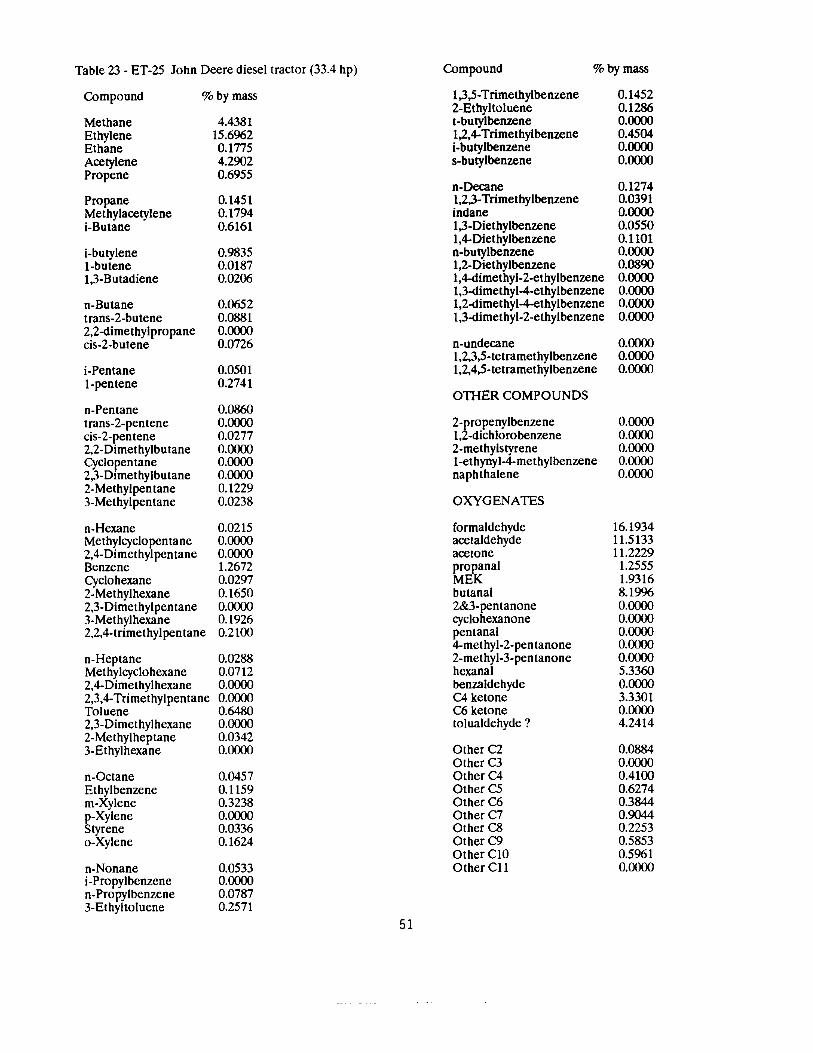
Table 23 - ET-25 John Deere diesel tractor (33.4 hp) Compound %by mass
Compound %by mass
Methane 4.4381 Ethylene 15.6962 Ethane 0.1775 Acetylene 4.2902 Propene 0.6955
Propane 0.1451 Methylacetylene 0.1794 i-Butane 0.6161
i-butylene 0.9835 I-butene 0.0187 1,3-Butadiene 0.0206
n-Butane 0.0652 trans-2-butene 0.0881 2,2-dimethylpropane 0.0000 cis-2-butene 0.0726
i-Pentane 0.0501 1-pentene 0.2741
n-Pentane 0.0860 trans-2-pentene 0.0000 cis-2-pentene 0.0277 2,2-Dimethylbutane 0.0000 Cyclopentane 0.0000 2,3-Dimethylbutane 0.0000 2-Methylpentane 0.1229 3-Methylpentane 0.0238
n-Hexane 0.0215 Methylcyclopentane 0.0000 2,4-Dimethylpentane 0.0000 Benzene 1.2672 Cyclohexane 0.0297 2-Methylhexane 0.1650 2,3-Dimethylpentane 0.0000 3-Methylhexane 0.1926 2,2,4-trimethylpentane 0.2100
n-Heptane 0.0288 Methylcyclohexane 0.0712 2,4-Dimethylhexane 0.0000 2,3,4-Trimethylpentane 0.0000 Toluene 0.6480 2,3-Dimethylhexane 0.0000 2-Methylheptane 0.0342 3-Ethylhexane 0.0000
n-Octane 0.0457 Ethylbenzene 0.1159 m-Xylene 0.3238 p-Xylene 0.0000 Styrene 0.0336 o-Xylene 0.1624
n-Nonane 0.0533 i-Propylbenzene 0.0000 n-Propylbenzene 0.0787 3-Ethyltoluene 0.2571
1,3,5-Trimethylbenzene 2-Ethyltoluene t-butylbenzene 1,2,4-Trimethylbenzene i-butylbenzene s-butylbenzene
n-Decane 1,2,3-Trimethylbenzene indane 1,3-Diethylbenzene 1,4-Diethylbenzene n-butylbenzene 1,2-Diethylbenzene 1,4-dimethyl-2-ethylbenzene 1,3-dimethyl-4-ethylbenzene 1,2-dimethyl-4-ethylbenzene 1,3-dimethyl-2-ethylbenzene
n-undecane 1,2,3,5-tetramethylbenzene 1,2,4,5-tetramethylbenzene
OTIIER COMPOUNDS
2-propenylbenzene 1,2-dichlorobenzene 2-methylstyrene l-ethynyl-4-methylbenzene naphthalene
OXYGENATES
formaldehyde acetaldehyde acetone propanal MEK butanal 2&3-pentanone cyclohexanone pentanal 4-methyl-2-pentanone 2-methyl-3-pentanone hexanal benzaldehyde C4 ketone C6 ketone tolualdehyde ?
Other C2 Other C3 Other C4 Other C5 Other C6 OtherC7 Other C8 OtherC9 OtherCIO Other Cll
0.1452 0.1286 0.0000 0.4504 0.0000 0.0000
0.1274 0.0391 0.0000 0.0550 0.1101 0.0000 0.0890 0.0000 0.0000 0.0000 0.0000
0.0000 0.0000 0.0000
0.0000 0.0000 0.0000 0.0000 0.0000
16.1934 11.5133 11.2229
1.2555 1.9316 8.1996 0.0000 0.0000 0.0000 0.0000 0.0000 5.3360 0.0000 3.3301 0.0000 4.2414
0.0884 0.0000 0.4100 0.6274 0.3844 0.9044 0.2253 0.5853 0.5961 0.0000
51

Table 24 - ET-26 Caterpillar diesel tractor (105 hp) Compound % by mass
Compound
Methane Ethylene Ethane Acetylene Propene
Propane Methylacetylene i-Butane methanol i-butylene I-butene 1,3-Butadiene
n-Butane trans-2-butene 2,2-dimethylpropane cis-2-butene ethanol i-Pentane 1-pentene
n-Pentane trans-2-pentene cis-2-pentene 2,2-Dimethylbutane Cyclopentane 2,3-Dimethylbutane 2-Methylpentane 3-Methylpentane
n-Hexane Methylcyclopen lane 2,4-Dimethylpentane Benzene Cyclohexane 2-Methylhexane 2,3-Dimethylpentane 3-Methylhexane 2,2,4-trimethylpentane
n-Heptane Methylcyclohexane 2,4-Dimethylhexane 2,3,4-Trimethylpentane Toluene 2,3-Dimethylhexane 2-Methylheptane 3-Ethylhexane
n-Octane Ethyl benzene m-Xylene p-Xylene Styrene o-Xylene
n-Nonane i-Propylbenzene n-Propylbenzene 3-Ethyltoluene
% by mass
14.5098 10.1569 0.1403 1.9637 0.8381
0.1360 0.0464 0.7237 0.0671 0.0820 0.1595 0.0000
0.0214 0.0000 0.0000 0.0000 0.0000 0.6018 0.0419
0.0411 0.0304 0.0243 0.2835 0.0000 0.0000 0.0909 0.0562
0.0493 0.0449 0.0000 0.9948 0.0000 0.0298 0.0308 0.2412 0.1487
0.0648 0.1118 0.0332 0.0000 0.6336 0.0000 0.0497 0.0628
0.1820 0.2080 0.4609 0.0000 0.0000 0.2466
0.3077 0.0362 0.1594 0.3243
1,3,5-Trimethylbenzene 0.2135 2-Ethyltoluene 0.2403 t-butylbenzene 0.0000 1,2,4-Trimethylbenzene 0.5648 i-butylbenzene 0.0867 s-butylbenzene 0.1194
n-Decane 0.7533 1,2,3-Trimethylbenzene 0.1203 indane 0.0000 1,3-Diethylbenzene 0.2251 1,4-Diethylbenzene 0.2782 n-butylbenzene 0.1718 1,2-Diethylbenzene 0.2827 1,4-dimethyl-2-ethylbenzene 0.1247 1,3-dimethyl-4-ethylbenzene 0.1691 1,2-dimethyl-4-ethylbenzene 0.1344 1,3-dimethyl-2-ethylbenzene 0.2097
n-undecane 0.0000 1,2,3,5-tetramethylbenzene 0.0000 1,2,4,5-tetramethylbenzene 0.0000
OTHER COMPOUNDS
2-propenylbenzene 0.0000 1,2-dichlorobenzene 0.0000 2-methylstyrene 0.0000 l-ethynyl-4-methylbenzene 0.0000 naphthalene 0.0000
OXYGENATES
formaldehyde 11.8394 acetaldehyde 9.3346 acetone 12.1517 propanal 0.0000 MEK 2.1803 butanal 2.1021 2&3-pentanone 0.0000 cyclohexanone 0.0000 pentanal 0.0000 4-methyl-2-pentanone 0.0000 2-methyl-3-pentanone 0.0000 hexanal 6.5379 benzaldehyde 0.0000 C4ketone 5.3008 C6ketone 0.0000 tolualdehyde ? 0.0000
Other C2 0.4278 Other C3 0.1190 Other C4 0.8926 Other CS 0.9351 Other C6 0.3810 Other C7 1.8863 Other C8 1.4887 Other C9 2.2931 Other ClO 2.7115 Other Cll 1.2882
52

Table 25 - ET-27 John Deere diesel tractor (150 hp) Compound % by mass
Compound
Methane Ethylene Ethane Acetylene Propene
Propane Methylacetylene i-Butane methanol i-butylene I-butene 1,3-Butadiene
n-Butane trans-2-butene 2,2-dimethylpropane cis-2-butene ethanol i-Pentane 1-pentene
n-Pentane trans-2-pentene cis-2-pentene 2,2-Dimethylbutane Cyclopentane 2,3-Dimethylbutane 2-Methylpentane 3-Methylpentane
n-Hexane Methylcyclopentane 2,4-Dimethylpentane Benzene Cyclohexane 2-Methylhexane 2,3-Dimethylpentane 3-Methylhexane 2,2,4-trimethylpentane
n-Heptane Methylcyclohexane 2,4-Dimethylhexane 2,3,4-Trimethylpentane Toluene 2,3-Dimethylhexane 2-Methylheptane 3-Ethylhexane
n-Octane Ethylbenzene m-Xylene p-Xylene Styrene o-Xylene
n-Nonane i-Propylbenzene n-Propylbenzene 3-Ethyltoluene
%by mass
2.8627 14.3604 0.3206 3.3971 5.1036
0.1650 0.6381 2.0247 0.0000 0.8301 1.2954 0.0483
0.1612 0.0497 0.0000 0.0000 0.0000 0.7649 0.1995
0.0655 0.1353 0.0624 0.2018 0.0310 0.0293 0.1791 0.0929
0.0945 0.1203 0.0309 1.7285 0.0214 0.1080 0.0607 0.3219 0.3230
0.1341 0.1577 0.0583 0.0000 1.2773 0.0319 0.1449 0.1048
0.2243 0.3284 0.4226 0.3128 0.2070 0.4198
0.1888 0.0490 0.2117 0.5515
1,3,5-Trimethylbenzene 0.3088 2-Ethyltoluene 0.2892 t-butylbenzene 0.0000 1,2,4-Trimethylbenzene 1.0521 i-butylbenzene 0.0687 s-butylbenzene 0.0908
n-Decane 0.3224 1,2,3-Trimethylbenzene 0.3564 indane 0.0000 1,3-Diethylbenzene 0.1559 1,4-Diethylbenzene 0.3130 n-butylbenzene 0.0000 1,2-Diethylbenzene 0.3164 1,4-dimethyl-2-ethylbenzene 0.0899 1,3-dimethyl-4-ethylbenzene 0.1802 1,2-d.imethyl-4-ethylbenzene 0.0869 l,3-dimethyl-2-ethylbenzene 0.2392
n-undecane 0.0000 1,2,3,5-tetramethylbenzene 0.0000 1,2,4,5-tetramethylbenzene 0.0000
OTHER COMPOUNDS
2-propenylbenzene 0.0000 1,2-dichlorobenzene 0.0000 2-methylstyrene 0.0000 l-ethynyl-4-methylbenzene 0.0000 naphthalene 0.0000
OXYGENATES
formaldehyde 13.0769 acetaldehyde 6.5077 acetone 8.4189 propanal l.0921 MEK 1.5153 butanal l.3352 2&3-pentanone 0.0000 cyclohexanone 0.0000 pentanal 0.0000 4-methyl-2-pentanone 0.0000 2-methyl-3-pentanone 0.0000 hexanal 3.4991 benzaldehyde 0.0000 C4 ketone 0.0000 C6 ketone 0.0000 tolualdehyde ? 2.0634
Other C2 0.0515 Other C3 1.0779 Other C4 3.3793 Other C5 2.5560 OtherC6 1.4104 OtherC7 1.7835 Other C8 2.0148 Other C9 2.4469 OtherClO 2.6487 Other Cll 0.5996
53

I. Discussion
1. Aldehyde Results
To investigate the efficiency of the aldehyde sampling system, separate analysis of the two series impingers used in the sampling train was performed. The diluted exhaust from a Snapper 21500C lawnmower was drawn through two impingers in series, at a flow of 432 mUmin for a period of 20.0 minutes. The contents of each impinger was analyzed separately. Table 26 shows the results of this study. As this Table shows, aldehydes and ketones are collected very efficiently, with 87 to 100% of 14 compounds being retained in the first impinger. While two impingers were used in all exhaust sampling tests, impinger contents were usually pooled into a single sample, to minimize analytical costs.
In order to explore analytical variability, sample ET-18 was analyzed in duplicate. Results for this diesel exhaust sample are shown in Table 27 . Replicate samples exhibited excellent agreement, with average deviations from the mean in the range of 0.1 to 2.7% for the 11 compounds detected.
Sampling variability was addressed by a series of tests using a Swirl Magic III 732053 lawnmower. Two consecutive 20.0 minute runs were performed on this engine. Table 28 shows that the sampling variability ranges from 0.5 to 13% (average 4%), for the 13 carbonyl compounds detected.
54
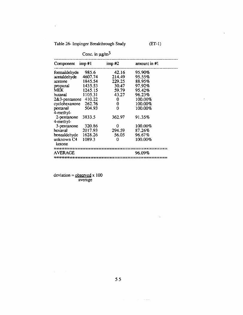
----------------------------------------------------------------------------------
Table 26- lmpinger Breakthrough Study (ET-1)
Cone. in µglm3
Component imp#l imp#2 amount in #1
formaldehyde 985.6 42.16 95.90% acetaldehyde 4607.74 214.49 95.55% acetone 1845.54 229.25 88.95% propanal 1435.53 30.47 97.92% MEK 1245.15 59.79 95.42% butanal 1105.31 43.27 96.23% 2&3-pentanone 410.22 0 100.00% cyclohexanone 262.76 0 100.00% pentanal 504.93 0 100.00% 4-methyl-
2-pentanone 3833.5 362.97 91.35% 4-methyl-
3-pentanone 320.86 0 100.00% hexanal 2017.93 294.59 87.26% benzaldehyde 1628.26 56.05 96.67% unknown C4 1089.3 0 100.00% ketone
AVERAGE 96.09%
deviation= observed x 100 average
55
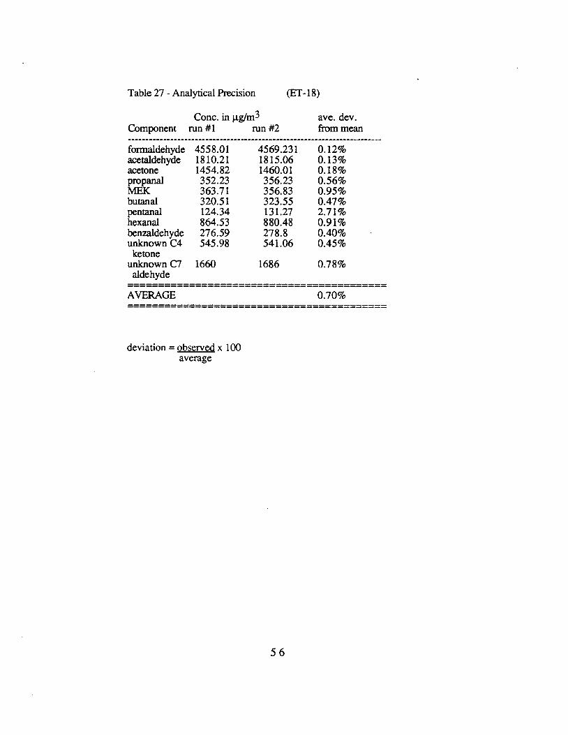
------------------------------------------------------------------------
Table 27 -Analytical Precision (ET-18)
Cone. in µg/m3 ave. dev. Component run #1 run #2 from mean
formaldehyde 4558.01 acetaldehyde 1810.21 acetone 1454.82 propanal 352.23 MEK 363.71 butanal 320.51 pentanal 124.34 hexanal 864.53 benzaldehyde 276.59 unknown C4 545.98 ketone
unknown C7 1660 aldehyde
AVERAGE
deviation= observed x 100 average
4569.231 1815.06 1460.01 356.23 356.83 323.55 131.27 880.48 278.8 541.06
1686
0.12% 0.13% 0.18% 0.56% 0.95% 0.47% 2.71% 0.91% 0.40% 0.45%
0.78%
0.70%
56
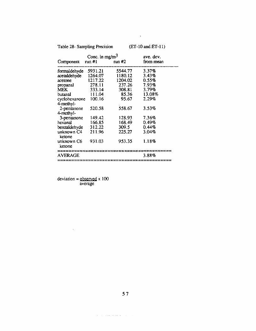
-----------------------------------------
Table 28- Sampling Precision (ET-10 and ET-11)
Cone. in mgtm3 ave. dev. Component run #1 run #2 from mean
formaldehyde 5931.21 5544.77 3.37% acetaldehyde 1264.07 1180.12 3.43% acetone 1217.22 1204.02 0.55% propanal 278.11 237.26 7.93% MEK 333.14 308.81 3.79% butanal 111.04 85.36 13.08% cyclohexanone 100.16 95.67 2.29% 4-methyl-2-pentanone 520.58 558.67 3.53%
4-methyl-3-pentanone 149.42 128.93 7.36%
hexanal 166.85 168.49 0.49% benzaldehyde 312.22 309.5 0.44% unknown C4 211.96 225.27 3.04% ketone
unknown C6 931.03 953.35 1.18% ketone
AVERAGE 3.88%
deviation= observed x 100 average
57
2. Hydrocarbon Replicate Samples
To assess variability introduced by the exhaust sampling process, several duplicate engine tests were conducted. Table 29 shows the results of duplicate samples taken from a 3 HP ,lawnmower. Similarly, Table 30 shows the results of duplicates taken from a Ford diesel tractor. The average variability by species was about 30 % relative to the mean.
3 Aldehyde and Ketone Concentrations
Table 31 shows the contribution of formaldehyde as a fraction of total aldehydes as well as of aldehydes plus ketones. For the engines tested. roughly 50 % of the total aldehyde content was attributed to formaldehyde, in agreement with previous studies. Results form two of the two-stroke engines (ET-1 and ET-4) showed very low aldehyde percentages. These results \\'.ere due to the very high non-aldehyde components in the exhaust of these engines. Actual aldehyde concentrations (expressed as micrograms per cubic meter) in diluted exhaust from these engines was comparable to that in other Category 2 sources.
Table 32 shows a camparison of formaldehyde concentrations for Category 2 and three sources. The average value for formaldehyde percentage in these sources was found to be around I %. For Category 3 sources, lower values of non-carbonyl hydrocarbons produced apparently elevated values for formaldehyde, with an average of around 15 %.
4. Hydrocarbon Concentrations
As discussed earlier, separate analytical results from methane, hydrocarbon and aldehyde analyses were collected into a combined data set for each engine. The major components (acetylene, ethylene, xylenes, toluene, trimethyl benzenes) were present at values comparable to other studiesl 1, 12.
However, the magnitude of the aldehyde contribution to the total hydrocarbon content was expected to be in the range of 8 to 14 %. In some of the samples taken, aldehydes were significantly higher than this. The effect is particularly obvious in the diesel exhaust tests (ET-17 through ET-27), which showed low values for total hydrocarbon. It should be noted that these high aldehyde values were not due to anomalously high aldehyde concentrations. Indeed. the aldehyde concentrations in the diluted diesel exhaust were comparable to those obtained for the other engines in this study. However, the total hydrocarbon content of these samples was significantly lower than the non-diesel engines. Thus, the aldehydes contributed a larger percentage of the total sampled hydrocarbons for these engines. A large fraction of the total hydrocarbon mass emitted by diesel engines is associated with the particulate phase. No particulate samples were taken for any engine in this study. It is therefore likely that the hydrocarbon speciation for the diesel engines tested would be significantly different if high molecular weight, particulate-associated hydrocarbons were included in the total.
The results for the analysis of the XAD-2 extracts taken from the diesel exhaust samples were all below the detection limit for the method. Taking a value of 2 micrograms for the lower limit of detection, this means that the heavy gas phase hydrocarbons were present at values of less than one percent of the total exhaust hydrocarbon values measured by GCFID. Mention should again be made of the fact that many of these compounds are in, or adsorbed onto the particulate phase of the exhaust, which was not sampled.
58
Consistent with the original Request for Proposal, results have been summarized for Category 2 and Category 3 Sources, as shown in Tables 32 and 33.
Examination of the overall results revealed that twelve compounds were responsible for roughly 50 % of the total hydrocarbon mass for all engines tested. In a few cases, these 12 components accounted for nearly 70 % of all hydrocarbons. These major components were: methane, ethylene, acetylene, propene, isopentane, benzene, toluene, m-xylene, pxylene, o-xylene, 1,2,4-trimethylbenzene and formaldehyde. Graphs of these profiles for Category 2 and Category 3 sources are shown in Figures 20 and 21.
59
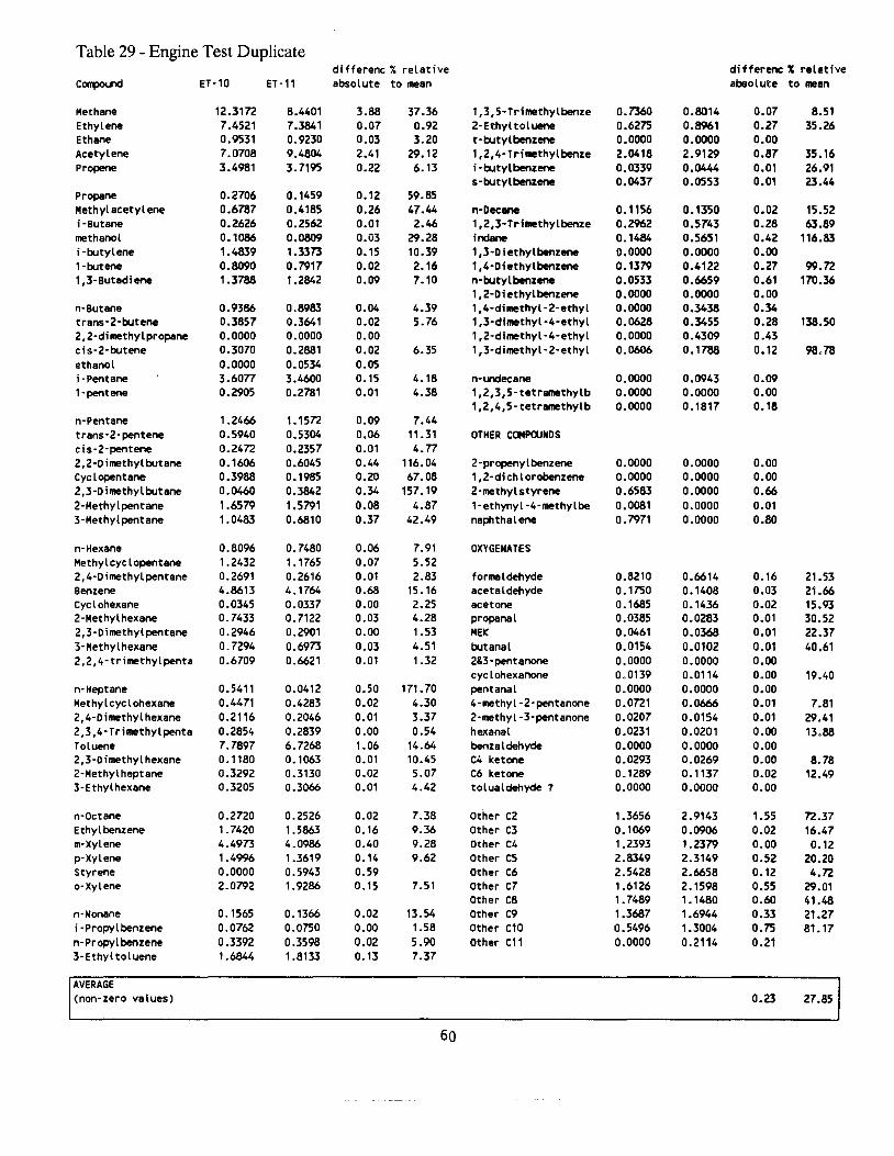
Table 29 - Engine Test Duplicate differenc % relative differenc: % relative
C~nd ET-10 ET-11 absolute to mean absolute to mean
Methane 12.3172 8.4401 3.88 37.36 1,3,S·Trimethylbenze 0.7360 0.8014 0.07 8.51 Ethylene 7.4521 7.3841 0.07 0.92 2-Ethyltoluene 0.6275 0.8961 0.27 35.26 Ethane 0.9531 0.9230 0.03 3.20 t·butylbenzene 0.0000 0.0000 0.00 Acetylene 7.0708 9.4804 2.41 29.12 1,2,4-Trimethylbenze 2.0418 2.9129 0.87 35.16 Propene 3.4981 3.7195 0.22 6.13 i ·butylbenzene 0.0339 0.0444 0.01 26.91
s·butylbenzene 0.0437 0.0553 0.01 23.44 Propane 0.2706 0.1459 0.12 59.85 Methyl acetylene 0.6787 0.4185 0.26 47.44 n·Dec- 0.1156 0.1350 0.02 15.52 i·Butane 0.2626 0.2562 0.01 2.46 1,2,3-Trimethylbenze 0.2962 0.5743 0.28 63.89 methanol 0.1086 0.0809 0.03 29.28 i~ 0. 1484 0.5651 0.42 116.83 i·butylene 1.4839 1.3373 0.15 10.39 1,3-Diathylbenzene 0.0000 0.0000 0.00 1 ·butene 0.8090 o. 7917 0.02 2.16 1,4-Diathylbenzene 0.1379 0.4122 0.27 99.72 1,3-Butadiene 1.3788 1.2842 0.09 7.10 n·butylbenzene 0.0533 0.6659 0.61 170.36
1,2-Diethylbenzene 0.0000 0.0000 0.00 n·Butane 0.9386 0.8983 0.04 4.39 1,4·dimethyl·2·ethyl 0.0000 0.3438 0.34 trans·2·butene 0.3857 0.3641 0.02 5.76 1,3·dimethyl•4·ethyl 0.0628 0.3455 0.28 138.50 2,2·dimethylpropane 0.0000 0.0000 0.00 1,2·dimethyl·4·ethyl 0.0000 0.4309 0.43 cis·2·butene 0.3070 0.2881 0.02 6.35 1,3·dimethyl·2·ethyl 0.0606 0.1788 0.12 98.78 ethanol 0.0000 0.0534 0.05 i ·Pentane 3.6077 3.4600 0.15 4.18 n·..-.clecane 0.0000 0.0943 0.09 1 ·pentene 0.2905 0.2781 0.01 4.38 1,2,3,5-tetramethylb 0.0000 0.0000 o.oo
1,2,4,5-tetrarnethylb 0.0000 0.1817 o. 18 n·Pentane 1.2466 1.1572 0.09 7.44 trans·2·pentene 0.5940 0.5304 0.06 11.31 OTHER COIIP<l.lNDS cis·2·pentene 0.2472 0.2357 0.01 4. 77 2,2-Dimethylbutane 0. 1606 0.6045 0.44 116. 04 2-propenylbenzene 0.0000 0.0000 0.00 Cyclopentane 0.3988 0.1985 0.20 67.08 1,2-dichlorobenzene 0.0000 0.0000 0.00 2,3-Dimethylbutane 0.0460 0.3842 0.34 157. 19 2·methylstyrene 0.6583 0.0000 0.66 2·Methylpentane 1.6579 1.5791 0.08 4.87 1·ethynyl·4·methylbe 0.0081 0.0000 0.01 3-Methylpentane 1.0483 0.6810 0.37 42.49 naphthalene 0.7971 0.0000 0.80
n·Hexane 0.8096 0.7480 0.06 7.91 OXYGENATES Methylcyclopentane 1.2432 1. 1765 0.07 5.52 2,4·Dimethylpentane 0.2691 0.2616 0.01 2.83 formaldehyde 0.8210 0.6614 0.16 21.53 Benzene 4.8613 4.1764 0.68 15. 16 acetaldehyde 0. 1750 0.1408 0.03 21.66 eye l ohexane 0.0345 0.0337 0.00 2.25 acetone 0.1685 0. 1436 0.02 15.93 2-Hethylhexane 0. 7433 0. 7122 0.03 4.28 propanal 0.0385 0.0283 0.01 30.52 2,3·Dimethylpentane 0.2946 0.2901 0.00 1.53 HEK 0.0461 0.0368 0.01 22.37 3-Hethylhexane 0.7294 0.6973 0.03 4.51 butanal 0.0154 0.0102 0.01 40.61 2,2,4·trimethylpenta 0.6709 0.6621 0.01 1.32 2&3-pentanone 0.0000 0.0000 0.00
cyclohexanone 0.0139 0 .0114 0.00 19.40 n·Heptane 0. 5411 0.0412 0.50 171. 70 pentanal 0.0000 0.0000 0.00 Hethylcyclohexane 0.4471 0.4283 0.02 4.30 4·methyl-2·pentanone 0.0721 0.0666 0.01 7.81 2,4·Dimethylhexane 0.2116 0.2046 0.01 3.37 2·methyl-3·pentanone 0.0207 0.0154 0.01 29.41 2,3,4-Trimethylpenta 0.2854 0.2839 0.00 0.54 hexanal 0.0231 0.0201 0.00 13.88 Toluene 7.7897 6.7268 1.06 14.64 benzaldehyde 0.0000 0.0000 0.00 2,3-Dimethylhexane 0.1180 o. 1063 0.01 10.45 C4 ketone 0.0293 0.0269 0.00 8.78 2-Methylheptane 0.3292 0.3130 0.02 5.07 C6 ketone 0.1289 0. 1137 0.02 12.49 3-Ethylhexane 0.3205 0.3066 0.01 4.42 tolualdehyde? 0.0000 0.0000 0.00
n·Octane 0.2720 0.2526 0.02 7.38 Other C2 1.3656 2.9143 1.55 72.37 Ethyl benzene 1. 7420 1.5863 0.16 9.36 Other C3 o. 1069 0.0906 0.02 16.47 m·Xylene 4.4973 4.0986 0.40 9.28 Other C4 1.2393 1.2379 0.00 0.12 p·Xylene 1.4996 1.3619 0.14 9.62 Other CS 2.8349 2.3149 0.52 20.20 Styrene 0.0000 0.5943 0.59 Other C6 2.5428 2.6658 0.12 4.72 o·Xylene 2.0792 1.9286 o. 15 7.51 Other C7 1.6126 2.1598 0.55 29.01
Other CB 1. 7489 1. 1480 0.60 41.48 n-Nonane 0. 1565 0.1366 0.02 13.54 Other C9 1.3687 1.6944 0.33 21.27 i·Propylbenzene 0.0762 0.0750 0.00 1 .58 Other C10 0.5496 1.3004 0.75 81.17 n·Propylbenzene 0.3392 0.3598 0.02 5.90 Other C11 0.0000 0.2114 0.21 3-Ethyltoluene 1.6844 1.8133 0. 13 7.37
IAVERAGE : (non-zero values) 0.23 27.851
60
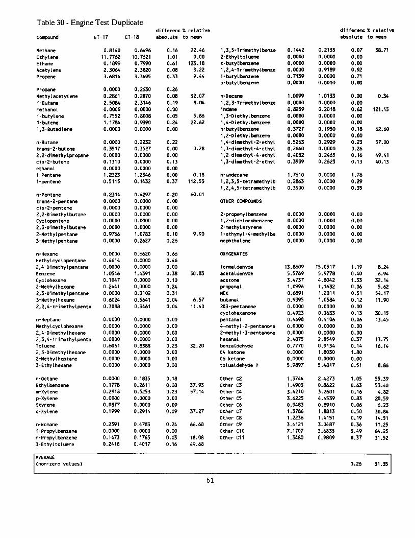
Table 30 - Engine Test Duplicate differenc % relative di fferenc % relative
C~und ET-17 ET-18 absolute to mean absolute to mean
Methane 0.8140 0.6496 0.16 22.46 1,3,5-Trimethylbenze o. 1442 0.2135 0.07 38.71 Ethylene 11. 7762 10.7621 1.01 9.00 2-Ethyltoluene 0.0000 0.0000 0.00 Ethane o. 1899 0.7990 0.61 123.18 t-butylbenzene 0.0000 0.0000 0.00 Acetylene 2.3064 2.3820 0.08 3.22 1,2,4-TriNthylbenze 0.0000 0.9189 0.92 Propene 3.6814 3.3495 0.33 9.44 i-butylbenzene o. 7139 0.0000 0.71
s·butylbenzene 0.0000 0.0000 0.00 Propane 0.0000 0.2630 0.26 Methyl acetylene 0.2661 0.2070 0.08 32.07 n·Oecane 1.0099 1.0133 o.oo 0.34 i-Butane 2.5084 2.3146 0.19 8.04 1,2,3·Trimethylbenze 0.0000 0.0000 0.00 methanol 0.0000 0.0000 0.00 indane 0.8259 0.2018 0.62 121.45 i-butylene 0.7552 0.8008 0.05 5.86 1,3-Diethylbenzene 0.0000 0.0000 0.00 1-butene 1. 1784 0.9390 0.24 22.62 1,4-Diethylbenzene 0.0000 0.0000 0.00 1,3-Butadiene 0.0000 0.0000 0.00 n·butylbenzene 0.3727 0.1950 0. 18 62.60
1,2-Diethylbenzene 0.0000 0.0000 0.00 n-Butane 0.0000 0.2232 0.22 1,4-dimethyl-2-ethyl 0.5263 0.2929 0.23 57.00 trans-2-butene 0.3517 0.3527 0.00 0.28 1,3-dimethyl-4-ethyl 0.2640 0.0000 0.26 2,2-dimethylpropane 0.0000 0.0000 0.00 1,2-dimethyl-4-ethyl 0.4082 0.2465 0.16 49.41 cis-2-butene 0.1310 0.0000 0.13 1,3-dimethyl-2-ethyl 0.3939 0.2623 0.13 40.13 ethanol 0.0000 0.0000 0.00 i-Pentane 1.2323 1.2346 0.00 0.18 n·undecane 1.7610 0.0000 1.76 1-pentene 0.5115 0. 1432 0.37 112 .53 1,2,3,5-tetramethylb 0.2863 0.0000 0.29
1,2,4,5-tetramethylb 0.3500 0.0000 0.35 n-Pentane 0.2314 0.4297 0.20 60.01 trans-2-pentene 0.0000 0.0000 0.00 OTHER COMPOUNDS cis-2-pentene 0.0000 0.0000 0.00 2,2-Dimethylbutane 0.0000 0.0000 0.00 2-propenylbenzene 0.0000 0.0000 0.00 Cyclopentane 0.0000 0.0000 o.oo 1,2-dichlorobenzene 0.0000 0.0000 0.00 2, 3-Dimethylbutane 0.0000 0.0000 0.00 2·methylstyrene 0.0000 0.0000 0.00 2-Methylpentane 0.9766 1.0783 0.10 9.90 1-ethynyl-4-methylbe 0.0000 0.0000 0.00 3-Methylpentane 0.0000 0.2627 0.26 naphthalene 0.0000 0.0000 0.00
n-Hexane 0.0000 0.6620 0.66 OXYGENATES Hethylcyclopentane 0.4614 0.0000 0.46 2,4-Dimethylpentane 0.0000 0.0000 o.oo formaldehyde 13.8609 15.0517 1.19 8.24 Benzene 1.0546 1.4391 0.38 30.83 acetaldehyde 5 .5769 5.9778 0.40 6.94 Cyclohexane 0.1047 0.0000 0. 10 acetone 3.4737 4.8042 1.33 32. 14 2-Hethylhexane 0.2441 0.0000 0.24 propanal 1.0996 1. 1632 0.06 5.62 2,3-Dimethylpentane 0.0000 0.3102 0.31 HEK 0.6891 1.2011 0.51 54.17 3-Hethylhexane 0.6024 0.5641 0.04 6.57 butanal 0.9395 1.0584 0. 12 11.90 2,2,4-trimethylpenta 0.3088 0.3461 0.04 11.40 2&3 -pentanone 0.0000 0.0000 0.00
cyclohexanone 0.4923 0.3633 0.13 30.15 n-Heptane 0.0000 0.0000 0.00 pentanal 0.4698 0.4106 0.06 13.45 Hethylcyclohexane 0.0000 0.0000 0.00 4-methyl-2-pentanone 0.0000 0.0000 0.00 2,4-Dimethylhexane 0.0000 0.0000 0.00 2-methyl-3-pentanone 0.0000 0.0000 0.00 2,3,4-Trimethylpenta 0.0000 0.0000 0.00 hexanal 2.4875 2.8549 0.37 13.75 Toluene 0.6061 0.8388 0.23 32.20 benzaldehyde 0. 7770 0.9134 0.14 16.14 2,3-Dimethylhexane 0.0000 0.0000 0.00 C4 ketone 0.0000 1.8030 1.80 2-Hethylheptane 0.0000 0.0000 0.00 C6 ketone 0.0000 0.0000 0.00 3-Ethylhexane 0.0000 0.0000 0.00 tolualdehyde? 5.9897 5.4817 0.51 8.86
n-Octane 0.0000 0. 1835 0. 18 Other CZ 1.3744 2.4273 1.05 55.39 Ethyl benzene 0.1778 0.2611 0.08 37.93 Other C3 1.4903 0.8622 0.63 53.40 m-Xylene 0.2918 0.5253 0.23 57.14 Other C4 3.4210 3.2601 0.16 4.82 p-Xylene 0.0000 0.0000 0.00 Other C5 3.6225 4.4539 0.83 20.59 Styrene 0.0877 0.0000 0.09 Other C6 0.9483 0.8910 0.06 6.23 a-Xylene 0.1999 0.2914 0.09 37.27 Other C7 1.3786 1.8813 0.50 30.84
Other CS 1.2236 1.4151 0.19 14.51 n-Nonane 0.2391 0.4783 0.24 66.68 Other C9 3.4121 3.0487 0.36 11.25 i-Propylbenzene 0.0000 0.0000 0.00 Other C10 7.1707 3.6835 3.49 64.25 n-Propylbenzene 0. 1473 0.1765 0.03 18.08 Other C11 1.3480 0.9809 0.37 31.52 3-Ethyltoluene 0.2418 0.4017 0.16 49.68
IAVERAGE : (non-zero values) 0.26 31.351
61

Table 31 - Aldehyde Composition
formaldehyde as formaldehyde as Component % of aldehydes % of aid+ ketones
ET-1 7.93 5.47 ET-2 60.53 43.32 ET-3 62.48 30.65 ET-4 14.66 7.28 ET-5 92.00 86.61 ET-6 47.13 33.28 ET-8 60.47 30.09 ET-9 42.30 30.56 ET-10 76.52 52.89 ET-11 76.84 51.87 ET-12 77.16 50.97 ET-13 65.96 35.16 ET-15 33.17 28.26 ET-17 54.98 38.66 ET-18 54.87 36.64 ET-20 55.20 39.09 ET-21 48.99 29.81 ET-23 58.67 40.51 ET-25 38.10 25.61 ET-26 39.71 23.94 ET-27 51.26 34.86
jAvera!le % 53.28 35.98
62
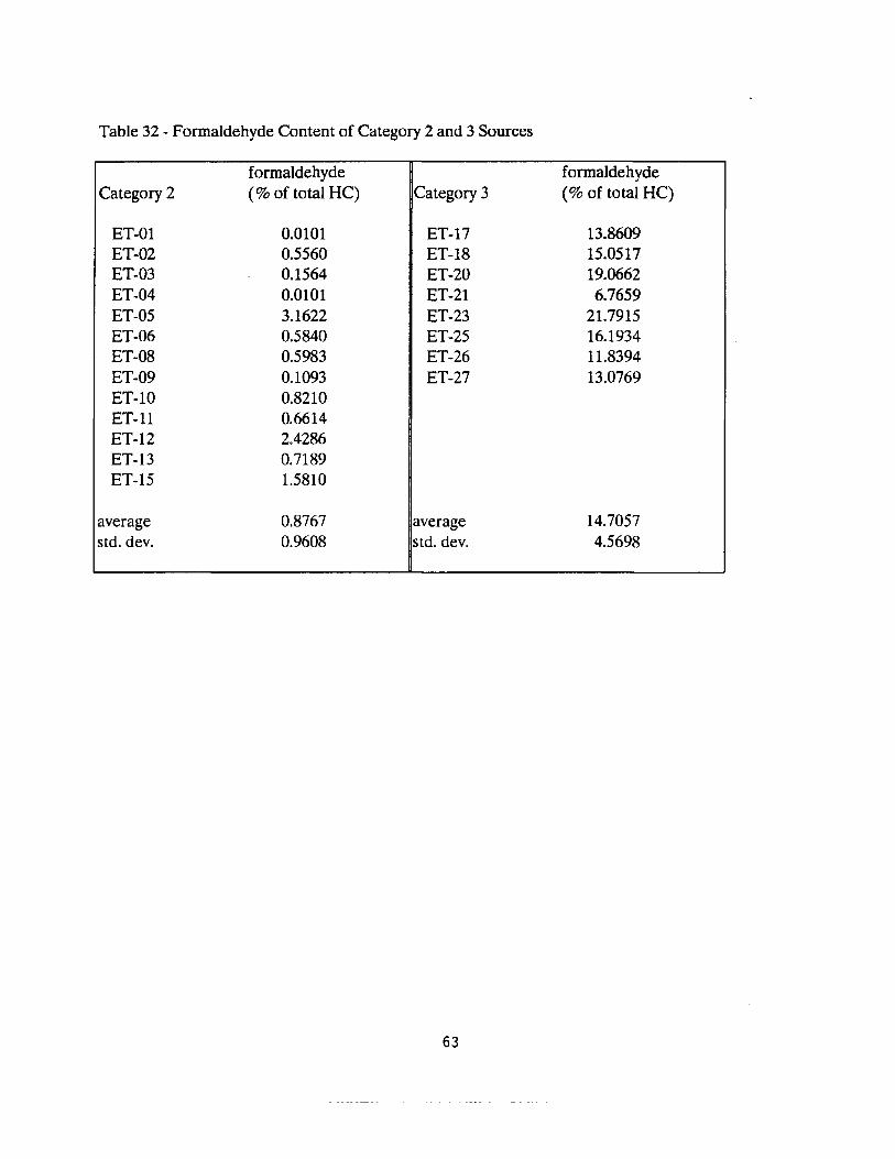
Table 32 - Formaldehyde Content of Category 2 and 3 Sources
formaldehyde Category 2 (% of total HC)
ET-01 0.0101 ET-02 0.5560 ET-03 0.1564 ET-04 0.0101 ET-05 3.1622 ET-06 0.5840 ET-08 0.5983 ET-09 0.1093 ET-10 0.8210 ET-11 0.6614 ET-12 2.4286 ET-13 0.7189 ET-15 1.5810
average 0.8767 std. dev. 0.9608
Category 3 formaldehyde (% of total HC)
ET-17 ET-18 ET-20 ET-21 ET-23 ET-25 ET-26 ET-27
13.8609 15.0517 19.0662 6.7659
21.7915 16.1934 11.8394 13.0769
average std. dev.
14.7057 4.5698
63
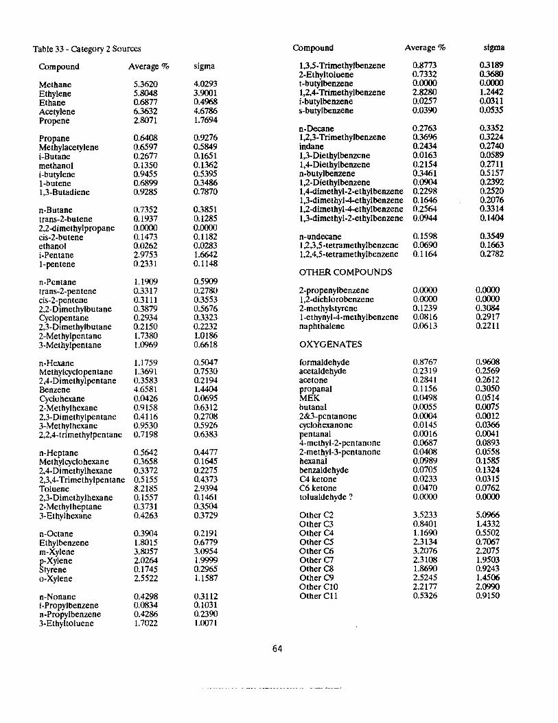
Table 33 - Category 2 Sources Compound Average% sigma
Compound Average% sigma 1,3,5-Trimethylbenzene 2-Ethyltoluene
0.8773 0.7332
0.3189 0.3680
Methane 5.3620 4.0293 t-butylbenzene 0.0000 0.0000 Ethylene Ethane
5.8048 0.6877
3.9001 0.4968
1,2,4-Trimethylbenzene i-butylbenzene
2.8280 0.0257
1.2442 0.0311
Acetylene 6.3632 4.6786 s-butylbenzene 0.0390 0.0535 Propene 2.8071 1.7694
n-Decane 0.2763 0.3352 Propane Methylacetylene i-Butane
0.6408 0.6597 0.2677
0.9276 0.5849 0.1651
1,2,3-Trimethylbenzene indane 1,3-Diethylbenzene
0.3696 0.2434 0.0163
0.3224 0.2740 0.0589
methanol 0.1350 0.1362 1,4-Diethylbenzene 0.2154 0.2711 i-butylene I-butene
0.9455 0.6899
0.5395 0.3486
n-butylbenzene 1,2-Diethylbenzene
0.3461 0.0904
0.5157 0.2392
1,3-Butadiene 0.9285 0.7870 1,4-dimethyl-2-ethylbenzene 0.2298 0.2520 1,3-dimethyl-4-ethylbenzene 0.1646 0.2076
n-Butane 0.7352 0.3851 1,2-dimethyl-4-ethylbenzene 0.2564 0.3314 trans-2-butene 0.1937 0.1285 1,3-dimethyl-2-ethylbenzene 0.0944 0.1404 2,2-dimethylpropane cis-2-butene
0.0000 0.1473
0.0000 0.1182 n-undecane 0.1598 0.3549
ethanol 0.0262 0.0283 1,2,3,5-tetramethylbenzene 0.0690 0.Hi63 i-Pentane 2.9753 1.6642 1,2,4,5-tetramethylbenzene 0.1164 0.2782 1-pentene 0.2331 0.1148
OTHER COMPOUNDS n-Pentane 1.1909 0.5909 trans-2-pentene cis-2-pentene 2,2-Dimethylbutane Cyclopentane 2,3-Dimethylbutane
0.3317 0.3111 0.3879 0.2934 0.2150
0.2780 0.3553 0.5676 0.3323 0.2232
2-propenylbenzene 1,2-dichlorobenzene 2-methylstyrene l-ethynyl-4-methylbenzene naphthalene
0.0000 0.0000 0.1239 0.0816 0.0613
0.0000 0.0000 0.3084 0.2917 0.2211
2-Methylpentane 1.7380 1.0186 3-Methylpentane 1.0969 0.6618 OXYGENATES
n-Hexane 1.1759 0.5047 formaldehyde 0.8767 0.9608 Methylcyclopentane 1.3691 0.7530 acetaldehyde 0.2319 0.2569 2,4-Dimethylpentane 0.3583 0.2194 acetone 0.2841 0.2612 Benzene 4.6581 1.4404 propanal 0.1156 0.3050 Cyclohexane 0.0426 0.0695 MEK 0.0498 0.0514 2-Methylhexane 0.9158 0.6312 butanal 0.0055 0.0075 2,3-Dimethylpentane 0.4116 0.2708 2&3-pentanone 0.0004 0.0012 3-Methylhexane 0.9530 0.5926 cyclohexanone 0.0145 0.0366 2,2,4-trimethylpentane 0.7198 0.6383 pentanal 0.0016 0.0041
4-methyl-2-pentanone 0.0687 0.0893 n-Heptane 0.5642 0.4477 2-methyl-3-pentanone 0.0408 0.0558 Methylcyclohexane 0.3658 0.1645 hexanal 0.0989 0.1585 2,4-Dimethylhexane 0.3372 0.2275 benzaldehyde 0.0705 0.1324 2,3,4-Trimethylpentane 0.5155 0.4373 C4 ketone 0.0233 0.0315 Toluene 8.2185 2.9394 C6 ketone 0.0470 0.0762 2,3-Dimethylhexane 0.1557 0.1461 tolualdehyde ? 0.0000 0.0000 2-Methylheptane 0.3731 0.3504 3-Ethylhexane 0.4263 0.3729 OtherC2 3.5233 5.0966
OtherC3 0.8401 1.4332 n-Octane 0.3904 0.2191 Other C4 1.1690 0.5502 Ethylbenzene 1.8015 0.6779 Other CS 2.3134 0.7067 m-Xylene 3.8057 3.0954 OtherC6 3.2076 2.2075 p-Xylene Styrene
2.0264 0.1745
1.9999 0.2965
Other C7 Other C8
2.3108 1.8690
1.9503 0.9243
o-Xylene 2.5522 1.1587 Other C9 Other CIO
2.5245 2.2177
1.4506 2.0990
n-Nonane 0.4298 0.3112 OtherCll 0.5326 0.9150 i-Propylbenzene 0.0834 0.1031 n-Propylbenzene 0.4286 0.2390 3-Ethyltoluene 1.7022 1.0071
64
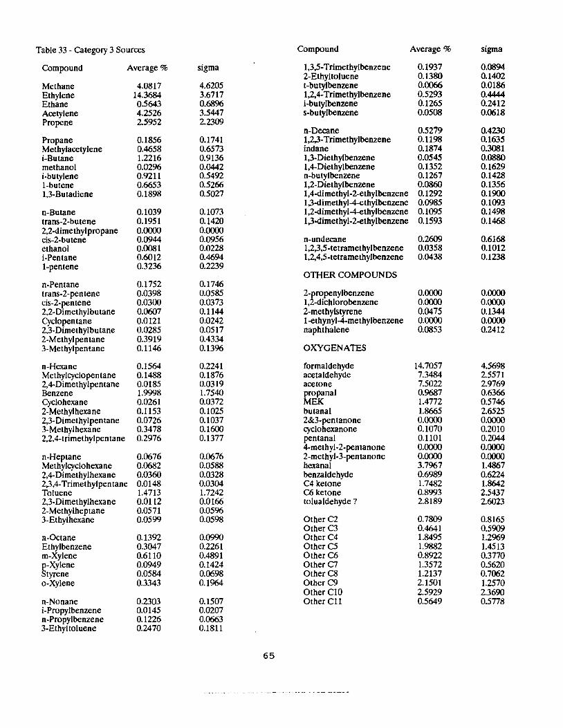
Table 33 - C.ategory 3 Sources Compound Average% sigma
Compound Average% sigma 1,3,5-Trimethylbenzene 2-Ethyltoluene
0.1937 0.1380
0.0894 0.1402
Methane 4.0817 4.6205 t-butylbenzene 0.0066 0.0186 Ethylene Ethane
14.3684 0.5643
3.6717 0.6896
1,2,4-Trimethylbenzene i-butylbenzene
0.5293 0.1265
0.4444 0.2412
Acetylene 4.2526 3.5447 s-butylbenzene 0.0508 0.0618 Propene 25952 22309
n-Decane 0.5279 0.4230 Propane Methylacetylene
0.1856 0.4658
0.1741 0.6573
1,2,3-Trimethylbenzene indane
0.1198 0.1874
0.1635 0.3081
i-Butane 1.2216 0.9136 1,3-Diethylbenzene 0.0545 0.0880 methanol i-butylene I-butene
0.0296 0.9211 0.6653
0.0442 0.5492 0.5266
1,4-Diethylbenzene n-butylbenzene 1,2-Diethylbenzene
0.1352 0.1267 0.0860
0.1629 0.1428 0.1356
1,3-Butadiene 0.1898 0.5027 1,4-dimethyl-2-ethylbenzene 0.1292 0.1900 1,3-dirnethyl-4-ethylbenzene 0.0985 0.1093
a-Butane 0.1039 0.1073 1,2-dimethyl-4-ethylbenzene 0.1095 0.1498 trans-2-butene 0.1951 0.1420 1,3-dimethyl-2-ethylbenzene 0.1593 0.1468 2,2-dimethylpropane cis-2-butene
0.0000 0.0944
0.0000 0.0956 n-undecane 0.2609 0.6168
ethanol 0.0081 0.0228 1,2,3,5-tetramethylbenzene 0.0358 0.1012 i-Pentane 0.6012 0.4694 1,2,4,5-tetramethylbenzene 0.0438 0.1238 1-pentene 0.3236 0.2239
OTHER COMPOUNDS n-Pentane 0.1752 0.1746 trans-2-pentene 0.0398 0.0585 2-propenylbenzene 0.0000 0.0000 cis-2-pentene 0.0300 0.0373 1,2-dichlorobenzene 0.0000 0.0000 2,2-Dimethylbutane 0.0607 0.1144 2-methylstyrene 0.0475 0.1344 Cyclopentane 0.0121 0.0242 1-ethynyl-4-methylbenzene 0.0000 0.0000 2,3-Dimethylbutane 0.0285 0.0517 naphthalene 0.0853 0.2412 2-Methylpentane 0.3919 0.4334 3-Methylpentane 0.1146 0.1396 OXYGENATES
a-Hexane 0.1564 0.2241 formaldehyde 14.7057 4.5698 Methylcyclopen tane 0.1488 0.1876 acetaldehyde 7.3484 25571 2,4-Dimethylpentane Benzene
0.0185 1.9998
0.0319 1.7540
acetone propanal
7.5022 0.9687
2.9769 0.6366
Cyclohexane 0.0261 0.0372 MEK 1.4772 0.5746 2-Methylhexane 0.1153 0.1025 butanal 1.8665 2.6525 2,3-Dimethylpentane 3-Methylhexane
0.0726 0.3478
0.1037 0.1600
2&3-pentanone cyclohexanone
0.0000 0.1070
0.0000 0.2010
2,2,4-trimethylpentane 0.2976 0.1377 pentanal 0.1101 0.2044 4-methyl-2-pentanone 0.0000 0.0000
a-Heptane 0.0676 0.0676 2-methyl-3-pentanone 0.0000 0.0000 Methylcyclohexane 0.0682 0.0588 hexanal 3.7967 1.4867 2,4-Dimethylhexane 0.0360 0.0328 benzaldehyde 0.6989 0.6224 2,3,4-Trimethylpentane 0.0148 0.0304 C4 ketone l.7482 l.8642 Toluene l.4713 l.7242 C6 ketone 0.8993 2.5437 2,3-Dimethylhexane 0.Dll2 0.0166 tolualdehyde ? 2.8189 2.6023 2-Methylheptane 0.0571 0.0596 3-Ethylhexane 0.0599 0.0598 Other C2 0.7809 0.8165
OtherC3 0.4641 0.5909 a-Octane 0.1392 0.0990 OtherC4 1.8495 1.2969 Ethylbenzene 0.3047 0.2261 OtherC5 l.9882 l.4513 m-Xylene 0.6110 0.4891 Other C6 0.8922 0.3770 p-Xylene 0.0949 0.1424 Other C7 l.3572 0.5620 Styrene 0.0584 0.0698 Other CS l.2137 0.7062 o-Xylene 0.3343 0.1964 Other C9 2.1501 1.2570
Other ClO 2.5929 2.3690 n-Nonane 0.2303 0.1507 OtherCll 0.5649 0.5778 i-Propylbenzene 0.0145 0.0207 n-Propylbenzene 0.1226 0.0663 3-Ethyltoluene 0.2470 0.1811
65
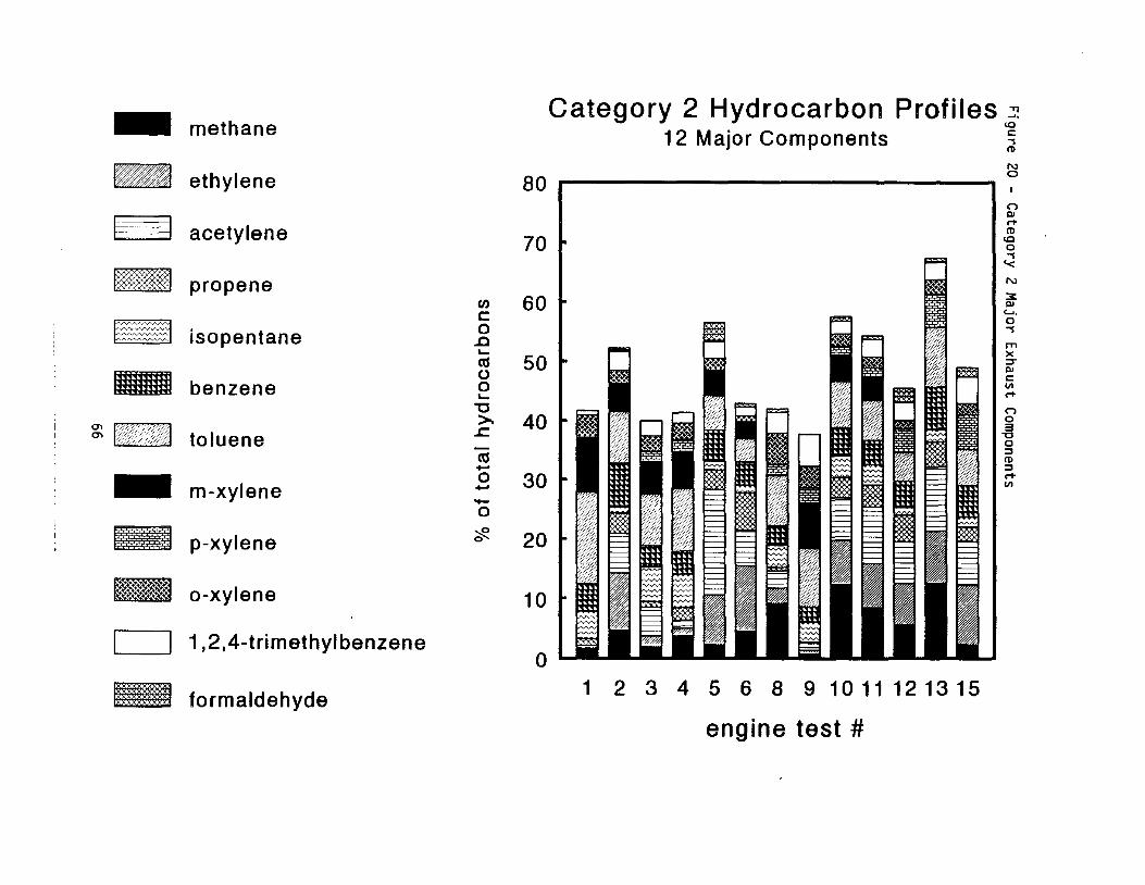
-
-
ESB
--mmmm
~ nm v;rn;1
-l!iii!!i;!!!;!;!I
~~
IHIIUmfl
methane
ethylene
acetylene
propane
isopentane
benzene
toluene
m-xylene
p-xylene
a-xylene
1,2,4-trimethylbenzene
formaldehyde
Category 2 Hydrocarbon Profiles ~ '° 12 Major Components ~ N
80 0
I I
0 L-1-...
n "'rt
70 ~ I cg l'D
"'I '< N
3: c......"'"'C
60 a "'I0
.!) rn.... )< ::,;-cu 50
0 "'C: VI0 rt....
"O n a>. 3.c. 40 -a a :::,cu . CD :::, rt
.... 0 ·}(:?( VII ii Ii~.... 30 -0
0 ~ 20
10
1 2 3 4 5 6 8 9 1011121315
engine test #
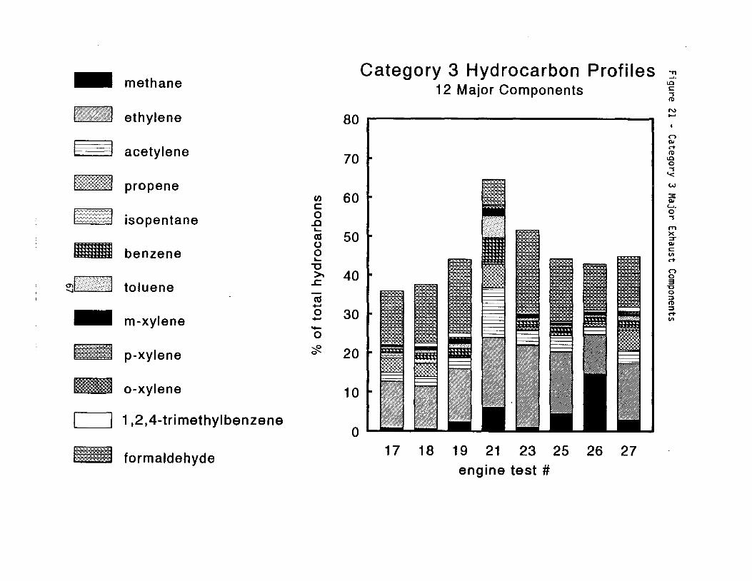
- methane
- ethylene
acetylene
propane -~ isopentane
benzene
dKF UUt! toluene
- m-xylene
!;!;!;! ;;;; ;i;i;!I p-xylene
- a-xylene
1,2,4-trimethylbenzene
tl)UHHI formaldehyde
Category 3 Hydrocarbon Profiles ~ .12 MaJor Components
~
~ (D
N ..... 80 .----------------
r, Ill rt
~70 (D
0 "'l '< w
u, 60 3: Ill c....C
0 0 "'l
.0 l'T1.....
cu 50 X :::r
0 Ill C0 Ill ..... rt
"O >,. r,
040.c. 3 "C 0 ~cu.... (D
0 rt.... 30 ~
Ill -0 ;:§?_0 20
10
0 25 26 2717 18 19 21 23
engine test #

III. References Cited
I Status Report : Emissions Inventory on Non-Farm, Farm and Lawn and Garden
Equipment, California Air Resources Board, Mobile Source Control Division, July
1893
2. Implement and Tractor, pp. 6-15, October 1988
3. Baugh, James, William Ray, Frank Black, Atmos. Environ., 21(10), 2077-2082
(1987)
4. MacDonald, J. Scott, Steven L. Plee, SAE Technical Paper 800185, Society of
Automotive Engineers (1980)
5. Lipari, Frank, Steven J. Swam, Environ. Sci. Technol., 19(1), 2077-2082 (1987)
6. Tejada, Silvestre B., Intern. J. Environ. Anal. Chem., 26, 167-185 (1986)
7. Warner-Selph, Mary Ann, Measurements o/Toxic Emissions from Gaosline
Powerered Light-Duty Vehicles, Report to California Air Resources Board, November
1989.
8. Fung, Kochy, AATMA, Inc., Personal Communication.
9. Compendium of Methods for the Detemination of Toxic Organic Compounds in
Ambient Air, U.S. Envirronmental Protection Agency, Environmental Monitoring
Systems Laboratory, Research Triangle Park, NC 27711
10. Procedures for the Sampling and Analysis of Atmospheric Toxic Compounds,
California Air Resources Board, Haagen-Smit Laboratory Division
11. Stigsby, Tejada, et al. , Environ. Sci. Technol., 21(5), 466 (1987)
12. Nelson, Atm. Env. 18, 79 (1884)
68
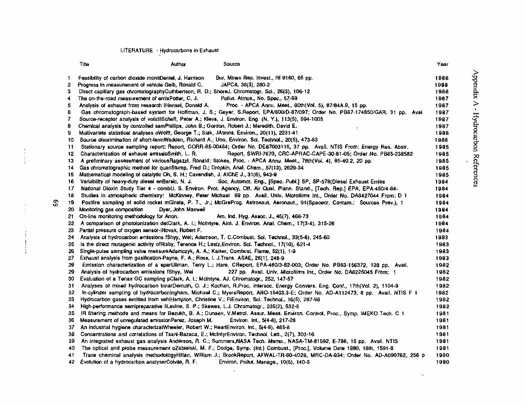
5
10
15
20
25
30
35
40
LITERATURE · Hydrocarbons in Exhaust
Title Author Source Year
Feasibility of carbon dioxide monitDaniel, J. Harrison Bur. Mines Rep. Invest., RI 9160, 85 pp. 1988 ►"O "O
2 3 4
Progress In measurement of vehicle Geib, Ronald C. JAPCA, 38(3), 280-2 Direct capillary gas chromatographyCuthbertson, A. D.; ShoreJ. Chromatogr. Sci., 26(3), 106-12 The on-the-road measurement of amlsPoner, C. J. Pollut. Atmos., No. Spec., 5?,-69
1988 1988 1987
0
5.. x·
6 7
Analysis of exhaust from research !Hensel, Donald A. Proc. • APCA Annu. Meet., 80th(Vol. 5), 87/84A.9, 15 pp. Gas chromatograph-based system for Hollman, J. S.; Gayer, S.Report, EPA/600/0-87/097; Order No. PB87-174850/GAR, 31
Source-receptor analysis of volatilSchell, Pater A.; Klavs, J. Environ. Eng. (N. Y.), 113(5), 994-1005 pp. Aval
1987 1987 1987
► ' ::r::
'< 8 Chemical analysis by controlled samPhillips, John B.; Gordon, Robert J.; Meredith, David E. 1987 ~9 Multivariate statistical analyses oWolll, George T.; Slak, JAtmos. Environ., 20(11), 2231-41 1986
11 Source discrimination of short-termWaddan, Richard A.; Uno, Environ. Sci. Technol., 20(5), 473-83 Stationary source sampling report: Report, CORR-85-00484; Order No. DE87003115, 37 pp. Avail. NTIS From: Energy Res. Abstr.
1986 1985
~ g-~
12 13 14
Characterization of exhaust emlssioSmith, L. R. Report, SWRl-7670, CRC-APRAC-CAPE-30-81-05; Order No. PB85-238582 A preliminary assessment of varlousRagazzl, Ronald; Stokes, Proc. - APCA Annu. Meet., 78th(Vol. 4), 85-40.2, 20 pp. Gas chromatographic method for quanStump, Fred D.; Drapkin, Anal. Chem., 57(13), 2629-34 Mathematical modeling of catalytic Oh, S. H.; Cavendish, J. AIChE J., 31(6), 943-9
1985 1985 1985 1985
:;,;, 0 @" @ ~
16 17
Variability of heavy-duty diesel enBarslc, N. J. Soc. Automot. Eng., [Spec. Publ.) SP, SP-578(Dlesel Exhaust Emiss National Dioxin Study Tier 4 • cornbU. S. Environ. Prat. Agency, Off. Air Qual. Plann. Stand., [Tech. Rep.) EPA, EPA-450/4-84-
1984 1984
0 0
"' 18 Studias In atmospheric chemistry: McKinney, Peter Michael 69 pp. Avail. Univ. Microfilms Int., Order No. DA8427044 From: D 1 1984
a,
'° 19 Postlira sampling of solid rocket mGirata, P. T., Jr.; McGreProg. Astronaut. Aeronaut., 91 (Spacecr. Contam.: Sources Prev.), 1 1984
Monitoring gas composition Oyer, John Maxwell 1984 21 On-line monitoring methodology for Anon. Am. Ind. Hyg. Assoc. J., 45(7), 468-73 1984 22 A comparison of photolonlzatlon detClark, A. I.; Mcintyre, Aini. J. Environ. Anal. Chem., 17(3-4), 315-26 1984 23 Partial pressure of oxygen sensor-lNovak, Robert F. 1984 24 Analysis of hydrocarbon emissions IShyy, Wei; Adamson, T. C.Combust. Sci. Technol., 33(5-6), 245-60 1983
Is the direct mutagenlc actlvlty ofRisby, Terence H.; Lestz,Environ. Sci. Technol., 17(10), 621-4 1983 26 Single-pulse sampling valve measureAdamczyk, A. A.; Kaiser, Combust. Flame, 52(1), 1-9 1983 27 Exhaust analysis from gasification-Payne, F. A.; Ross, I. J.Trans. ASAE, 26(1), 246-9 1983 28 Emission characterization of a sparUllman, Terry L.; Hare, CReport, EPA-460/3-82-003; Order No. PB83-156372, 128 pp. Avail. 1982 29 Analysis of hydrocarbon emissions IShyy, Wal 227 pp. Avail. Univ. Microfilms Int., Order No. DA8225045 From: 1 1982
Evaluation of a Tanax GC sampling pClark, A. I.; McIntyre, AJ. Chromatogr., 252, 147-57 1982 31 Analyses of mixed hydrocarbon blnarDemuth, 0. J.; Kochan, A.Proc. lntarsoc. Energy Convers. Eng. Cont., 17th(Vol. 2), 1104-9 1982 32 In-cylinder sampling of hydrocarbonlngham, Michael C.; MyersReport, ARO-15403.3-E; Order No. AD-A112473, 8 pp. Avail. NTIS F 1 1982 33 Hydrocarbon gases emitted from vehiHampton, Christina V.; PiEnviron. Sci. Technol., 16(5), 287-98 1982 34 High-performance samlpreparative lilevine, S. P.; Skawas, L.J. Chromatogr., 235(2), 532-5 1982
IA filtering methods and means for Bezukh, B. A.; Dunaav, V.Metrol. Assur. Meas. Environ. Control, Proc., Symp. IMEKO Tech. C 1 1981 36 Measurement of unregulated emlsslonPerez, Joseph M. Environ. Int., 5(4-6), 217-28 1981 37 An industrial hygiene characterizatWheeler, Robert W.; HaarlEnviron. Int., 5(4-6), 485-8 1981 38 Concentrations and correlations of Tsani-Bazaca, E.; MclntyrEnviron. Technol. Lett., 2(7), 303-16 1981 39 An Integrated exhaust gas analysis Anderson, R. C.; Summers.NASA Tech. Memo., NASA-TM-81592, E-786, 15 pp. Avail. NTIS 1981
The optical and probe measurement oZabielski, M. F.; Dodge, Symp. (Int.) Combust., [Proc.), Volume Date 1980, 18th, 1591-8 1981 41 Trace chemical analysis methodologyHillan, William J.; BrookReport, AFWAL-TR-80-4028, MRC-DA-934; Order No. AD-A090762, 256 p 1980 42 Evolution of a hydrocarbon analyserColvile, R. F. Environ. Pollut. Manage., 10(5), 140-3 1980
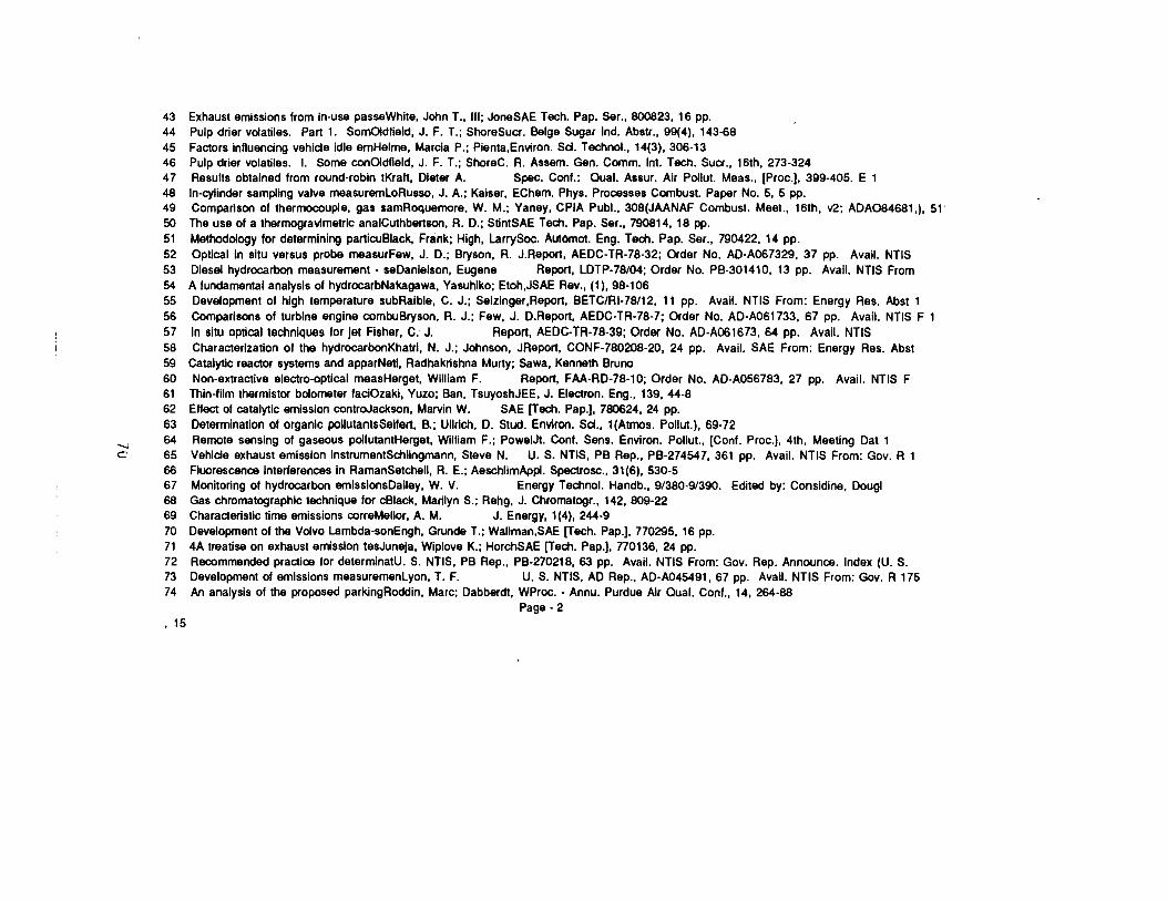
43 44 45 46 47 48 49 50 51 52 53 54 55 56 57 58 59 60 61 62 63 64 65 66 67 68 69 70 71 72 73 74
Exhaust emissions from in-use passeWhite, John T., Ill; JoneSAE Tech. Pap. Ser., 800823, 16 pp. Pulp drier volatiles. Part 1. SomOldfield, J. F. T.; ShoreSucr. Beige Sugar Ind. Abstr., 99(4), 143-68 Factors influencing vehlde Idle emHelme, Marcia P.; Pienta.Environ. Sd. Technol., 14(3), 306-13 Pulp drier volatiles. I. Some conOldfield, J. F. T.; ShoreC. R. Assam. Gen. Comm. Int. Tech. Suer., 16th, 273-324 Results obtained from round-robin tKraft, Dieter A. Spec. Cont.: Qual. Assur. Air Pollut. Meas., [Proc.), 399-405. E 1 In-cylinder sampling valve measurernloRusso, J. A.; Kaiser, EChem. Phys. Processes Combust. Paper No. 5, 5 pp. Comparison of thermocouple, gas samRoquemore, W. M.; Yaney, CPIA Publ., 308(JAANAF Combust. Meet., 16th, v2; ADA084681,), 51· The use of a thermogravimetric analCuthbertson, A. D.; StintSAE Tech. Pap. Ser., 790814, 18 pp. Methodology tor determining panicuBlack, Frank; High, LarrySoc. Automot. Eng. Tech. Pap. Ser., 790422, 14 pp. Optical In situ versus probe measurFew, J. D.; Bryson, A. J.Report, AEDC-TR-78-32; Order No. AD-A067329, 37 pp. Avail. NTIS Diesel hydrocarbon measurement• seDanlelson, Eugene Report, LDTP-78/04; Order No. PB-301410, 13 pp. Avail. NTIS From A fundamental analysis of hydrocarbNakagawa, Yasuhiko; Etoh,JSAE Rev., (1), 98-106 Development of high temperature subRalble, C. J.; Selzlnger,Report, BETC/Rl-78/12, 11 pp. Avail. NTIS From: Energy Res. Abst 1 Comparisons of turbine engine combuBryson, R. J.; Few, J. D.Report, AEDC-TR-78-7; Order No. AD-A061733, 67 pp. Avail. NTIS F 1 In situ optical techniques for jet Fisher, C. J. Report, AEDC-TR-78-39; Order No. AD-A061673, 64 pp. Avail. NTIS Characterization of the hydrocarbonKhatrl, N. J.; Johnson, JReport, CONF-780208-20, 24 pp. Avail. SAE From: Energy Res. Abst
Catalytic reactor systems and apparNetl, Radhakrishna Murty; Sawa, Kenneth Bruno Non-extractive electro-optical measHerget, William F. Report, FAA-RD-78-10; Order No. AD-A056783, 27 pp. Avail. NTIS F
Thin-film thermistor bolometer faciOzakl, Yuzo; Ban, TsuyoshJEE, J. Electron. Eng., 139, 44-8 Effect of catalytic emission controJackson, Marvin W. SAE (Tech. Pap.), 780624, 24 pp. Determination of organic pollutantsSellert, B.; Ullrich, D. Stud. Environ. Sd., l(Atrnos. Pollut.), 69·72 Remote sensing of gaseous pollutantHerget, William F.; PowelJt. Cont. Sens. Environ. Pollut., (Cont. Proc.), 4th, Meeting Dal 1......
C: Vehlde exhaust emission lnstrumentSchllngmann, Steve N. U. S. NTIS, PB Rep., PB-274547, 361 pp. Avail. NTIS From: Gov. R 1 Fluorescence interferences In RamanSetchell, A. E.; AeschlimAppl. Spectrosc., 31(6), 530-5 Monitoring of hydrocarbon ernissionsDalley, W. V. Energy Technol. Handb., 9/380-9/390. Edited by: Considine, Dougl Gas chromatographic technique for cBlack, Marilyn S.; Rehg, J. Chromatogr., 142, 809-22 Characteristic time emissions correMellor, A. M. J. Energy, 1 (4), 244-9 Development of the Volvo Lambda-sonEngh, Grunde T.; Wallman.SAE (Tech. Pap.), 770295, 16 pp. 4A treatise on exhaust emission tesJuneja, Wlplove K.; HorchSAE (Tech. Pap.), 770136, 24 pp. Recommended practice for determinatU. S. NTIS, PB Rep., PB-270218, 63 pp. Avail. NTIS From: Gov. Rep. Announce. Index (U. S. Development of emissions measurernenlyon, T. F. U.S. NTIS, AD Rep., AD-A045491, 67 pp. Avail. NTIS From: Gov. R 175 An analysis of the proposed parkingRoddin, Marc; Dabberdt, WProc. - Annu. Purdue Air Oual. Cont., t 4, 264-88
Page - 2 , 15
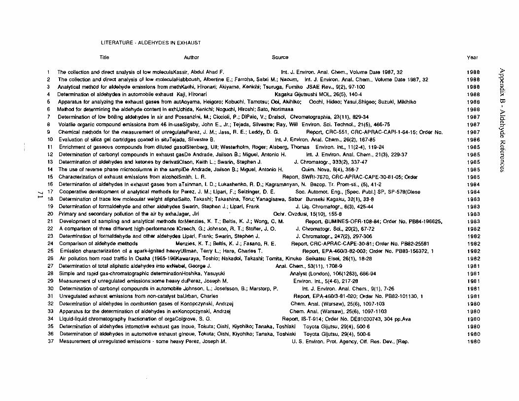
5
10
15
20
25
30
35
LITERATURE - ALDEHYDES IN EXHAUST
Title Author Source Year
1 The collection and direct analysis of low molerulaKassir, Abdul Ahad F. Int. J. Environ. Anal. Chem., Volume Date 1987, 32 1988 ►"O 2 3
The collection and direct analysis of low moleculaHabboush, Albertine E.; Farroha, Sabri M.; Naoum, Int. J. Environ. Anal. Chem., Volume Date 1987, 32 Analytical method for aldehyde emissions from methKachi, Hlronari; Akiyama, Kenlchi; Tsuruga, Fumiko JSAE Rev., 9(2), 97-100
1988 1988
'8 ::, P-
4 Determination of aldehydes in automobile exhaust Kaji, Hironari Kagaku Gijutsushi MOL, 26(5), 140-4 1988 ><' Apparatus for analyzing the exhaust gases from autAoyama, Heigoro; Kobuchi, Tamotsu; Ooi, Akihlko; Oochi, Hideo; Yasui,Shigeo; Suzuki, Mikihiko 1988 l:IJ
6 7
Method for determining the aldehyde conten1 in exhUchida, Kenichi; Noguchi, Hiroshi; Sato, Norimasa Determination of low bolling aldehydes In air and Possanzini, M.; Ciocioli, P.; DiPalo, V.; Draisci, Chromatographia, 23(11), 829-34
1988 1987
I
►5: 8 9
11 12
Volatile organic compound emissions from 46 in-useSigsby, John E., Jr.; Tejada, Silvestre; Ray, Will Environ. Sci. Technol., 21(5), 466-75 Chemical methods for the measurement of unregulatePerez, J.M.; Jass, R. E.; Leddy, D. G. Report, CAC-551, CRC-APRAC-CAPl-1-64-15; Order No. Evaluation of silica gel cartridges coated in situTejada, Silvestre B. Int. J. Environ. Anal. Chem., 26(2), 167-85 Enrichment of gaseous compounds from diluted gasotStenberg, Ult; Westerholm, Roger; Alsberg, Thomas Environ. Int., 11(2-4), 119-24 Determination of carbonyl compounds in exhaust gasDe Andrade, Jailson B.; Miguel, Antonio H. Int. J. Environ. Anal. Chem., 21 (3), 229-37
1987 1987 1986 1985 1985
(l ::,-
'< P-(l
:;i;; (l
ct· @
13 Determination of aldehydes and ketones by derivatiOlson, Keith L.; Swarin, Stephen J. J. Chromatogr., 333(2), 337-47 1985 ::, (")
14 The use of reverse phase microcotumns in the samplDe Andrade, Jailson B.; Miguel, Antonio H. Ouim. Nova, 8(4), 356-7 1985 (l en
Characterization of exhaust emissions from alcoholSmith, L.A. Report, SWRl-7670, CRC-APRAC-CAPE-30-81-05; Order 1985 16 Determination of aldehydes in exhaust gases from aTslnman, I. D.; Lukashenko, A. D.; Kagramanyan, N. Bezop. Tr. Prom-sti., (5), 41-2 1984
--... 17 Cooperative development of analytical methods for Perez, J. M.; Lipari, F.; Selzlnger, D. E. Soc. Automot. Eng., [Spec. Publ.) SP, SP-578(Diese 1984 ,_. 18 Determination of trace low molerular weight allphaSaito, Takashi; Takashina, Toru; Yanagisawa, Sabur Bunseki Kagaku, 32(1 ), 33-8 1983
19 Determination of formaldehyde and other aldehydes Swarin, Stephen J.; Lipari, Frank J. Liq. Chromatogr., 6(3), 425-44 1983 Primary and secondary pollution of the air by exhaJager, Jiri Ochr. Ovzdusl, 15(10), 155-8 1983
21 Development of sampling and analytical methods forMenzies, K. T.; Bellis, K. J.; Wong, C. M. Report, BUMINES-OFR-108-84; Order No. PB84-196625, 1983 22 A comparison of three different high-performance !Creech, G.; Johnson, A. T.; Stoffer, J. 0. J. Chromatogr. Sci., 20(2), 67-72 1982 23 Determination of formaldehyde and other aldehydes Lipari, Frank; Swarin, Stephen J. J. Chromatogr., 247(2), 297-306 1982 24 Comparison of aldehyde methods Menzies, K. T.; Bellis, K. J.; Fasano, A. E. Report, CRC-APRAC-CAPE-30-81; Order No. PB82-25581 1982
Emission characterization of a spark-ignited heavyUllman, Terry L.; Hare, Charles T. Report, EPA-460/3-82-003; Order No. PB83-156372, 1 1982 26 Air pollution from road traffic in Osaka (1965-196Kawaraya, Toshia; Nakadot, Takashi; Tomita, Kinuko Seikatsu Eisai, 26(1), 18-28 1982 27 Determination of total aliphatic aldehydes into exNebel, George J. Anal. Chem., 53(11 ), 1708-9 1981 28 Simple and rapid gas-chromatographic detenninationHoshika, Yasuyuki 29 Measurement of unregulated emissions:some heavy duPerez, Joseph M.
Determination of carbonyl compounds in automobile Johnson, L.; Josefsson, B.; Marstorp, P. 31 Unregulated exhaust emissions from non-catalyst baUrban, Charles 32 Determination of aldehydes in combustion gases of Konopczynski, Andrzej 33 Apparatus for the determination of aldehydes in exKonopczynski, Andrzej
Analyst (London), 106(1263), 686-94 1981 Environ. Int., 5(4-6), 217-28 1981
Int. J. Environ. Anal. Chem., 9(1 ), 7-26 1981 Report, EPA-460/3-81-020; Order No. PB82-101130, 1 1981
Chem. Anal. (Warsaw), 25(6), 1097-103 1980 Chem. Anal. (Warsaw), 25(6), 1097-1103 1980
34 Liquid-liquid chromatography fractionation of orgaColgrove, S. G. Report, IS-T-914; Order No. DE81030743, 304 pp.Ava 1980 Determination of aldehydes intomotive exhaust gas Inoue, Tokuta; Oishi, Kiyohiko; Tanaka, Toshiaki Toyota Gijutsu, 29(4), 500-6 1980
36 Determination of aldehydes in automotive exhaust glnoue, Tokuta; Oishi, Kiyohiko; Tanaka, Toshiaki Toyota Gijutsu, 29(4), 500-6 1980 37 Measurement of unregulated emissions - some heavy Perez, Joseph M. U. S. Environ. Prat. Agency, OH. Res. Dev., [Rep. 1980
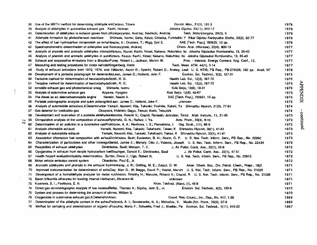
38 39 40 41
42 43 44
45 46
47
48
49 50
51 52
53
54 55
56 57
58 59 60
61 62 63
64
65
66 67
68
69 70
71 72
73 74
75
76
77 78
Use of the MBTH method for determining aldehyde emCarpiuc, Tiberiu Constr. Mas., 31 (3), 181-3 Analysis of aldehydes in automotive exhaust gas Kachi, Hironari Jidosha Gijutsu, 33(11), 912-17
Determination of aldehydes in exhaust gases from pKonopczynski, Andrzej; Siedlecki, Andrzej Tech. Motoryzacyjna, 29(3), 5 Aldehyde formation by photochemical reactions Shimada, lsamu; Saito, Keizo; Chisaka, Fumitake; Y Kikai Gijutsu Kenkyusho Shoho, 32(2), 62-77
The effect of fuel hydrocarbon composition on exhaHosaka, K.; Onodera, T.; Wigg, Eric E. SAE [Tech. Pap.), 780625, 12 pp.
Spectrophotometric determination of aldehydes and Konopczynski, Andrzej Chern. Anal. (Warsaw), 22(4), 809-13 Analysis of phenols and aromatic aldehydes intomobKimura, Kazoo; Kachi, Kasei; Nakano, Nobuhiko; Ito Jidosha Gijutsukai Rombunshu, 13, 35-40
Analysis of phenols and aromatic aldehydes in autoKimura, Kazuo; Kachi, Kosei; Nakano, Nobuhiko; Ito Jidosha Gijutsukai Rombunshu, 13, 35-40 Exhaust and evaporative emissions from a BrazilianFurey, Roben L.; Jackson, Marvin W. Proc. - lntersoc. Energy Convers. Eng. Cont., 12,
Measuring and testing procedures for motor vehideKlingenberg, Horst Tech. Mess. ATM, 44(1), 3-14 Study of exhaust emissions from 1972, 1974, and 19Manin, Aaron R.; Specht, Roben D.; Anstey, Lesli U. S. NTIS, PB Rep., PB-274526, 182 pp. Avail. NT
Development of a ponable polarograph for determinMclean, James D.; Holland, John F. Environ. Sci. Technol., 9(2), 127-31 Tentative method for determination of benzaldehydeSmlth, A.G. Health Lab. Sci., 12(2), 167-70
Tentative method for determination of benzaldehydeSmlth, A.G. Health Lab. Sci., 12(2), 167-70 tomobfle exhaust gas and photochemical smog Shimada, lsamu Kuki Seijo, 12(6), 18-31
Analysis of automotive exhaust gas Aoyama, Hyogoro Kuki Seijo, 12(6), 46-67
The diesel as an alternativetomobile engine Henein, Naeim A. SAE [Tech. Pap.), 750931, 15 pp. Ponabfe polarographic analyzer and quick polarogrMclean, James D.; Holland, John F. unknown
Analysis of automobile emissions.II.Determination Yamaki, Naoomi; Kita, Takaaki; Yoshida, Kolchi; Ta Shimadzu Hyoron, 31(3), 77-91 Gas detector for oxldizable gas Obayashi, Hidehito; Gejyo, Tetsuo; Kudo, Tetsuichi
Development and evaluation of a por1able aldehydesMarcote, Roland V,; Chand, Ramesh; Johnston, Tirnot Anal. lnstrum., 11, 31-43 ..._. Comparative analysis of the composition of exhaustRytvinskii, G. N.; Raikov, I. Ya. Avto. Prom., 39(4), 8-10 N Determination of air pollution in a locomotive cabProkhorov, A. A.; Novikova, I. S.; Pervukhina, I. Gig. Sanit., (11 ), 66-9
Analysis oftomobile exhaust Yamaki, Naoomi; Kita, Takaaki; Takahashi, Takeo; K Shimadzu Hyoron, 30(1 ), 41-61 Analysis of automobile exhaust Yamaki, Naoomi; Kita, Takaaki; Takahashi, Takeo; K Shimadzu Hyoron, 30(1), 41-61 Association oftornative fuel composition with exhauDimitriades, Basil; Eccleston, B. H.; Sturm, G. P. U. S. Nat. Tech. Inform. Serv., PB Rep., No. 22260
Characterization of paniculates and other nonreguGentel, James E.; Manary, Otto J.; Valenta, Joseph U. S. Nat. Tech. Inform. Serv., PB Rep., No. 22424 Reactivities of exhaust aldehydes Dimitriades, Basil; Wesson, T. C. J. Air Pollut. Conb'. Ass., 22(1), 33-8 Oyxgenates In exhaust from simple hydrocarbon fuelSiezinger, Donald E.; Dimitriades, Basil J. Air Pollut. Contr. Ass., 22(1 ), 47-51
Health hazard evaluation/toxicity determination. Bunon, David J.; Ugo, Roben N. U. S. Nat. Tech. Inform. Serv., PB Rep., No. 22915 Motor vehicle emission control system Oberdorler, Paul E., Jr.
Aromatic aldehydes and phenols in the exhaust lromHinkamp, J. B.; Griffing, M. E.; Zutaut, D. W. Amer. Chem. Soc., Div, Petrol. Chem., Prepr., 16(2
Improved instrumentation for determination of exhaDay, Alan G., Ill; Beggs, David P.; Vestal, Marvin U. S. Nat. Tech. Inform. Serv., PB Rep., No. 21025
Development of a formaldehyde analyzer for motor vJohnston, Timothy H.; Marcote, Roland V.; Chand, R U. S. Nat. Tech. Inform. Serv., PB Rep., No. 21026 Boron trifluoride etherates for treating internal Herbsman, Abraham M. unknown
Krasnova, S. I.; Pavlikova, E. N. Khim. Tekhnol. (Kiev), (1 ), 46-8
Direct gas chromatographic analysis al low moleculBellar, Thomas A.; Sigsby, John E., Jr. Environ. Sci. Technol., 4(2), 150-6 System and process for determining the amount of alnnes, William B.
Oxygenates in automotive exhaust gas.11.DetermininAnon. Coord. Res. Counc., Inc., Rep., No. 417, 1-26 Determination of the aldehyde content in the exhauParimskii, A. I.; Bondarenko, N. A.; Mikhailov, V. Maslo-Zhir. Prom., 35(9), 37-9
Method for sampling and determination of organic cFracchia, Mario F.; Schuette, Fred J.; Mueller, Pe Environ. Sci. Technol., 1(11), 915-22
1979 1979 1979
1978 1978
1977 1077 1977
1977
1977 1976
1975
1975 1975 ?; 1975 'ti
trJ1975 s1975
1975 ~ 1974
1974 0
1973 0::, p.1973 ::,
1973 C: 0 p..1973
1973 1973
1973 1972 1972
1972 1972
1971 1971
1971
1971
1971 1970
1970
1969 1969
1967

Appendix C - Photographs of Selected Sampling setups
73
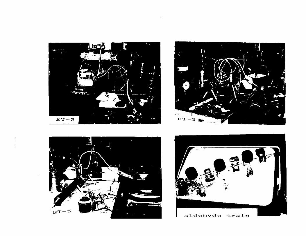
ET-3
alclel~ycle train
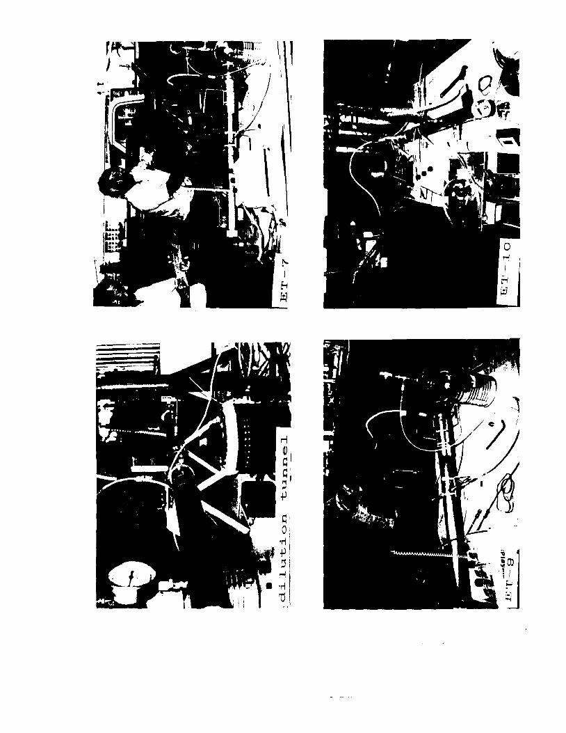
..... I ·~ , 'I
,, '
\
I ~ ; t -~
~I
0' •r(
• +1
' rl - . • .,,
7j
~
!ro ; I
f-.. ~
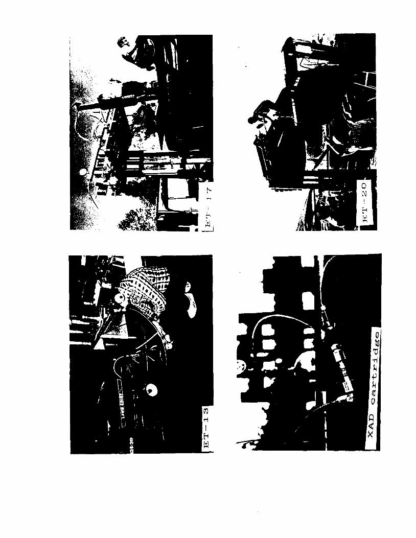
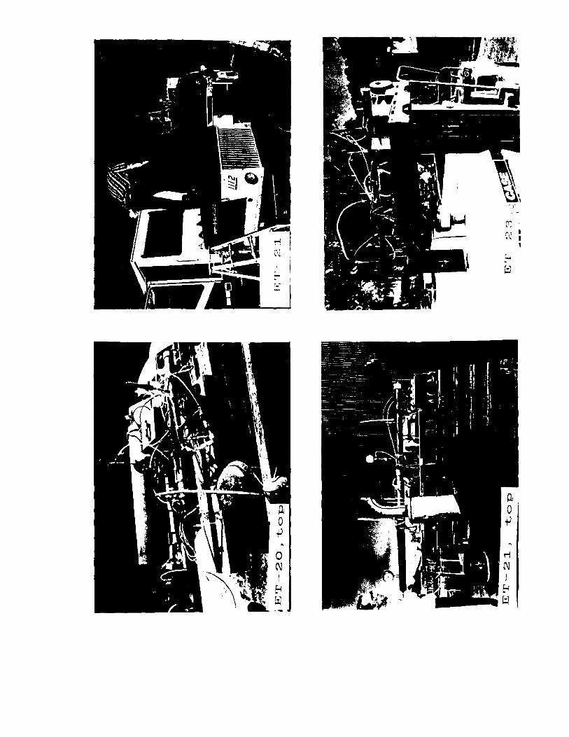
rrJ ,._, I ·~ \ I,


Appendix D - Protocol for Sampling Engine Exhaust Emissions
78

Appendix D - Protocol for Sampling Engine Exhaust Emissions
1. Am,licability
1.1 The procedures described herein will be applied to sampling exhaust from selected
utility and heavy-duty engines.
2. Method
2.1 Engine exhaust CO2 content will be determined by NDIR analysis.
2. 2 Engine exhaust will be pulled into a dilution mini-tunnel by the action of low
pressure in a sonic nozzle placed in the dilution tunnel.
2. 3 Engine exhaust will be diluted with zero air in the approximate ratio of 1: 10.
2.4 Diluted exhaust will be sampled simultaneously at two pons.
2.4.1 Samples for hydrocarbon analysis will be collected in evacuated,
passivated stainless steel canisters.
2.4.2 Samples for aldehyde analysis will be pulled through a series of two
midget impingers filled with acidified acetonitirile and DNPH.-
2.5 Analysis for hydrocarbons will be performed using gas chromatography with flame
ionization or mass spectrometric detection, as appropriate.
3. Components
3.1- A cylinder of zero air, containing less than 0.1 PPM hydrocarbons.
3.1.1 A size 3 or size 2 cylinder of Ultra Zero Air, from Matheson, Cucamonga,
CA.
3.1.2 A pressure regulator capable of providing cylinder outlet pressures in the
range of0-200 PSIG, MODEL lH, Matheson, Cucamonga, CA.
3.2 Pressure gauge, 0-200 PSIG, #63-3122, from Matheson, Cucamonga, CA.
3.3 Magnetic gauge, 1-5 inches of water, Dwyer Instruments, Michigan City, IN, or a
slack tube nanometer capable of reading in same range.
3.4 SUMMA-passivated stainless steel canister, 3.2 liters.
3.5 Dilution mini-tunnel.
3.6 DNPH, acetonitrile, hydrochloric acid, Baxter Scientific, Irvine CA.
3.7 An air sampling pump, capable of flow rates in the range of 1-2 liters/min.
3.8 A rotameter, Ace Glass, Vineland, NJ.
3. 9 A dry test meter to total aldehyde sampling volume. Alternatively, an electronic soap
bubble flowmeter.
4. Procedure
4.1 Engine information is recorded on data sheet.
4.2 Perform engine compression check, if appropriate.
4.3 Inspect spark plug, and replace as appropriate.
4.4 Inspect fuel level. Fill with an amount of fuel (pre-mixed, if required) adequate for
duration of test
4.5 Assemble hydrocarbon sampling train.
4.5.1 Check pressure in stainless steel canister.
4.6 Assemble aldehyde sampling train.
4.6.1 Set pump flow rate at desired value (0.4 to 2.0 !/min).
4.7 Attach zero air source to dilution tunnel.
4.8 Set zero air pressure and flow, in accordance with desired dilution ratio.
4.9 Start and warm up test engine.
4.10 With engine under load, measure CO2 level in exhaust with NDIR exhaust gas
analyzer.
4.11 Insert tunnel probe into engine exhaust stream.
4.12 Check CO2 content of exhaust leaving dilution tunnel, using NDIR analyzer.
4.13 When CO2 content has reached steady state, record time and begin sampling.
4.13.1 With aldehyde sampling pump running, open aldehyde tunnel port.
4.13.2 Collect aldehyde sample for 10-15 minutes.
4.13.3 Concurrent with aldehyde sample collection, open hydrocarbon tunnel
port.
4.13.4 Open canister valve, and allow sample to fill canister. Orifice dimensions
should be selected to allow 10-15 minutes for filling to be completed.
4.13.5 At end of sampling interval, close aldehyde and hydrocarbon ports.
4.13.6 Record canister final pressure, and close canister valve.
4.13.7 Shut off aldehyde sampling pump, remove sampling cartridge, seal both
ends with caps, and place into screw capped culture vial.
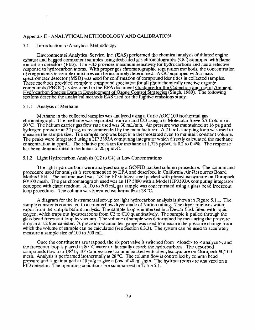
Appendix E - ANALYTICAL METHODOLOGY AND CALIBRATION
5.1 Introduction to Analytical Methodology
Environmental Analytical Service, Inc. (EAS) performed the chemical analysis of diluted engine exhaust and bagged component samples using dedicated gas chromatographs (GC) equipped with flame ionization detectors (FID). The FID provides maximum sensitivity for hydrocarbons and has a selective response to hydrocarbon atoms. With proper gas chromatographic separation methods, the concentration of components in complex mixtures can be accurately determined. A GC equipped with a mass spectrometer detector (MSD) was used for confirmation of compound identities in collected samples. These methods provided complete compound speciation for all photochemically reactive organic compounds (PROC) as described in the EPA document Guidance for the Collection and use of Ambient Hydrocarbon Species Data in Development of Ozone Control Strategies (Singh, 1980). The following sections describe the analytical methods EAS used for the fugitive emissions study.
5.1.1 Analysis of Methane
Methane in the collected samples was analyzed using a Carie AGC 100 isothermal gas chromatograph. The methane was separated from air and CO using a 6' Molecular Sieve 5A Column at. 50 °C. The helium carrier gas flow rate used was 30 mUmin. Air pressure was maintained at 16 psig and hydrogen pressure at 22 psig, as recommended by the manufacturer. A 2.0 mL sampling loop was used to measure the sample size. The sample loop was kept in a thermostated oven to maintain constant volume. The peaks were integrated using a HP 3393A computing integrator which directly calculated the methane concentration in ppmC. The relative precision for methane at 1,725 ppbvC is 0.2 to 0.4%. The response has been demonstrated to be linear to 20 ppmvC.
5.1.2 Light Hydrocarbon Analysis (C2 to C4) at Low Concentrations
The light hydrocarbons were analyzed using a GC/FID packed column procedure. The column and procedure used for analysis is recommended by EPA and described in California Air Resources Board Method 104. The column used was 1/8" by 10' stainless steel packed with phenyl-isocyanate on Durapack 80/100 mesh. The gas chromatograph used was an HP 5890 with a Model HP3393A computing integrator equipped with chart readout. A 100 to 500 mL gas sample was concentrated using a glass bead freezeout loop procedure. The column was operated isothermally at 28 °C.
A diagram for the instrumental set-up for light hydrocarbon analysis is shown in Figure 5.1.1. The sample canister is connected to a counterflow dryer made of Nafion tubing. The dryer removes water vapor from the sample before analysis. The sample loop is immersed in a Dewar flask filled with liquid oxygen, which traps out hydrocarbons from C2 to ClO quantitatively. The sample is pulled through the glass bead freezeout loop by vacuum. The volume of sample was determined by measuring the pressure drop in a 1.2 liter canister. A precision vacuum test gauge was used to measure the pressure change from which the volume of sample can be calculated (see Section 6.3.3). The system can be used to accurately measure a sample size of 100 to 500 mL.
Once the constituents are trapped, the six port valve is switched from <load> to <analyze>, and the freezeout loop is placed in 80 °C water to thermally desorb the hydrocarbons. The desorbed compounds flow to a 1/8" by 10' stainless steel column packed with phenylisocyanate on Durapack 80/100 mesh. Analysis is performed isothermally at 28 °C. The column flow is controlled by column head pressure and is maintained at 20 psig to give a flow of 40 mUmin. The hydrocarbons are analyzed on a FID detector. The operating conditions are summarized in Table 5.1.
79
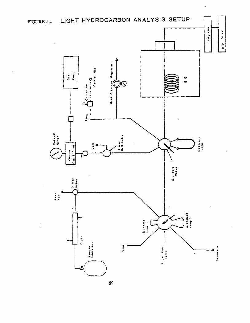
LIGHT HYDROCARBON ANALYSIS SETUPFIGURE 5.1
0. ..•c
g. 0
~ 0
u UI
. .y ..
-. ..;; -. >•
"'
. ~ : ., C
.. c
.,..
go

TABLE 5.1
OPERA!?IBG CONDr%IOBS
Flows -Helium 30 ml/min Hydrogen 30 ml/min
Gas Pressures -Helium (Column Pressure) .40 psigHydrogen (Flame) 24 psig Air (Flame) 15 psig
Temperature Program - SOC Detector Temperature - 150 C Sample Size - 1.0 ml
LIGHT HYDROCABBOBS
Flows -Helium 29 ml/min Hydrogen 31 ml/min Air 340 ml/min
Gas Pressures -Helium (Column Pressure> 40 psigHydrogen (Flame) 17.5 psigAir (Flame) 34 psig
Temperature Program - 30 C Detector Temperature - 250 C Sample Size - 500 ml
HEAVY HYDROCABBONS -
Flows -Air 420 ml/minNitrogen 43 ml/min
Gas Pressures -Hydrogen (Column Pressure> 7 psigHydrogen (Flame) 17 psigAir <Flame) 35 ps~gNitrogen (Make-up Gas) 30 psig
Temperature Program- -20C for 2 min, Program Rate 6 C/minDetector Temperature - 275 C Sample Size - 500 ml
81
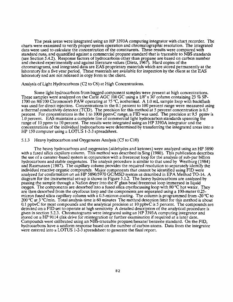
The peak areas were integrated using an HP 3393A computing integrator with chart recorder. The charts were examined to verify proper system operation and chromatographic resolution. The integrated data were used to calculate the concentration of the constituents. These results were compared with standard runs, and quantified against a commercial propane standard that is traceable to NBS standards (see Section 5.4.2) .. Response factor~ of ~ydrocarbons other_than pr~ane are bas_ed on carbon number and checked expenmentally and agamst hterature values (Dietz, 1967). Hard copies of the chromatograms, and integrated data are EAS proprietary materials which are stored permanently at the laboratory for a five year period. These materials are available for inspection by the client at the EAS laboratory and are not released in copy form to the client.
Analysis of Light Hydrocarbons (C2 to C6) at High Concentrations.
Some light hydrocarbons from bagged component samples were present at high concentrations. These samples were analyzed on the Carle AGC 100 GC using a 1/8" x 30' column containing 23 % SP-1700 on 80/100 Chromosorb PAW operating at 75 °C, isothermal. A 1.0 mL sample loop with backflush was used for direct injection. Concentrations in the 0.1 percent to 100 percent range were measured using a thermal conductivity detector.(TCD). The precision for this method at 5 percent concentration is 0.5 percent. For concentrations in the 1 to 1000 ppmvC range, a FID was used. The precision at 9.5 ppmv is 1.0 percent. EAS maintains a complete line of commercial light hydrocarbon standards spanning the range of 10 ppmv to 10 percent. The results were integrated using an HP 3393A integrator and the concentrations of the individual hydrocarbons were determined by transferring the integrated areas into a HP 150 computer using a LOTUS 1-2-3 spreadsheet.
5.1.3 Heavy hydrocarbon and Oxygenates Analysis (C5 to ClO)
The heavy hydrocarbons and oxygenates (aldehydes and ketones) were analyzed using an HP 5890 with a fused silica capillary column. This method was described in Sing (1980). This publication describes the use of a canister-based system in conjunction with a freezeout loop for the analysis of sub-par billion hydrocarbons and stable oxygenates. The analysis procedure is similar to that used by Westburg (1984) and Rasmussen (1987). The capillary column provides the required resolution to separately identify the individual reactive organic compounds. Major components that cannot be identified using FID were analyzed for confirmation on an HP 5890/5970 GC/MSD system as described in EPA Method TO-14. A diagram for the instrumental set-up is shown in Figure 5.1.2. The heavy hydrocarbons are analyzed by passing the sample through a Nafion dryer into the 8" glass bead freezeout loop immersed in liquid oxygen. The components are desorbed into a fused silica cryofocussing loop with 80 °C hot water. They are then desorbed from the cryofocus loop and the components are separated using a 100-meter 0.25-micron fused silica capillary column with a 0.5-micron coating. The column is programmed from -20 °C to 200 °Cat 3 °C/min. Total analysis time is 60 minutes The method detection limit for this method is about 0.1 ppbvC for most compounds and the analytical precision at 10 ppbvC is 5 percent. The compounds are detected on a FID set to operate at high sensitivity A detailed description of the analytical procedure is given in section 5.2.3. Chromatograms were integrated using an HP 3393A cqmputing integrator and stored on a HP 9114 disk drive for reintegration or further examination if required at a later date. Compounds were calibrated using an NBS-traceable propane/hexane/ benzene standard. On the FID, hydrocarbons have a uniform response based on the number of carbon atoms. Data from the integrator were entered into a LOTUS 1-2-3 spreadsheet to generate the final report.
82
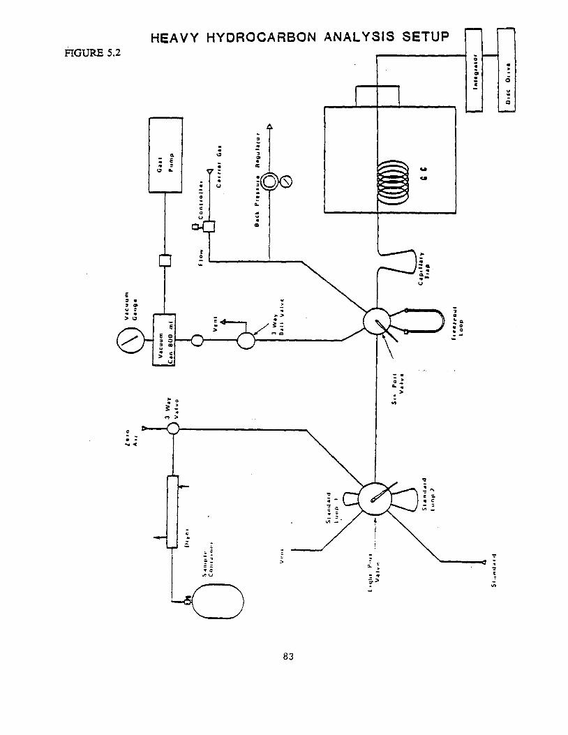
0
FIGURE 5.2 . >
Q
.. ..
HEAVY HYDROCARBON ANALYSIS SETUP
......
..
>
.;;
83
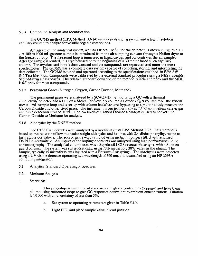
5.1.4 Compound Analysis and Identification
The GC/MS method (EPA Method TO-14) uses a cryotrapping system and a high resolution capillary column to analyze for volatile organic compounds.
A diagram of the analytical system, with an HP 5970 MSD for the detector, is shown in Figure 5.1.3 . A 100 to 1000 mL gaseous sample is introduced from the air sampling canister through a Nafion dryer to the freezeout loop. The freezeout loop is immersed in liquid oxygen and concentrates the air sample. After the sample is loaded, it is cryofocussed onto the beginning of a 30 meter fused silica capillary column. The cryofocused loop is then warmed and the compounds are separated and enter the mass spectrometer. The GC/MS has a complete data system capable of collecting, storing, and interpreting the data collected. The GC/MS is tuned and operated according to the specifications outlined in EPA SW 846 Test Methods. Compounds were calibrated by the external standard procedure using a NBS traceable Scott-Marrin air standards. The relative standard deviation of the method is 20% at 5 ppbv and the MDL is 0.5 ppbv for most compounds.
5.1.5 Permanent Gases (Nitrogen, Oxygen, Carbon Dioxide, Methane)
The permanent gases were analyzed by a SCAQMD method using a GC with a thermal conductivity detector and a FID on a Molecular Sieve 5A column a Poropak QIN column mix. the system uses a 1 mL sample loop and is set-up with column backflush and bypassing to simultaneously measure the Carbon Dioxide and other fixed gases. The instrument is run isothermally at 70° C with helium carrier gas and has a detection limit of 0.05%. For low levels of Carbon Dioxide a catalyst is used to convert the Carbon Dioxide to Methane for analysis.
5.1.6 Aldehydes by the DNPH method
The Cl to C4 aldehydes were analyzed by a modification of EPA Method TO5. This method is based on the reaction of low molecular weight aldehydes and ketones with 2,4-dinitrophenylhydrazine to form stable derivatives. The source gases were sampled using midget impingers filled with acidified DNPH in acetonitrile. An aliquot of the impinger contents was analyzed using high performance liquid chromatography. The analytical column used was a Supelcosil LC18 reverse phase type, with a Supelco guard column. The system was run isocratically, using 70% methanol I 30% water as the eluant. The sample, typically 15 microliters, was injected with a Pressure-Lok syringe. The aldehydes were detected using a UV-visible detector operating at a wavelength of 360 nm, and quantified using an HP 3393A computing integrator.
5.2 Analytical Standard Operating Procedures
5.2.1 Methane Analysis
1. Standards
This procedure is used to load standards at high concentrations (5 ppmv) and have them diluted using calibrated loops to give GC responses equivalent to ambient concentrations. Dilution is 1/1000 with an uncertainty of less than 5%.
a. Set system to operating parameters given in Table 5.1.b.
b. Light FID, and place sample valve in load position.
84
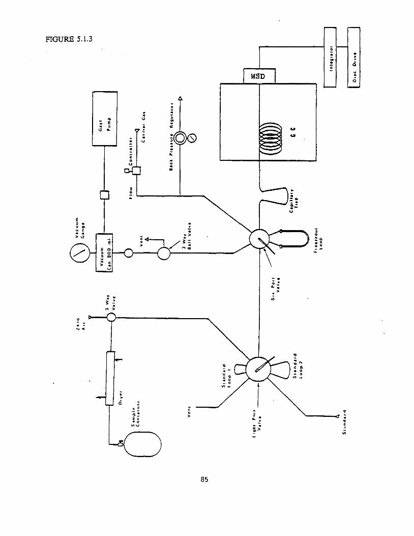
• •
FIGURE 5.1.3 0
... C
MSD
.. -.. "' E..- ,
~ .:
...CL"' UI
--..o_ Q. ..
>
"'
:. . -..◄
Q
Q
85
5.2.2
c. Connect standard cylinder to sampling line.
d. Open valve on standard cylinder and let bubble for 3 seconds to flush loop. Close valve.
e. Rotate sample valve to inject position, start integrator.
f. At end of run turn sample valve to load position.
g. Disconnect standard cylinder.
2. Ambient Air Samples
This procedure can be used to load low pressure samples in stainless steel sample canisters, and to load low pressure standards at simulated ambient concentrations.
a. Set system to operating parameters given in Table 5.1.b.
b. Light FID, turn sample valve to load position.
C. Connect sample canister to sampling line.
d. Open valve on sample canister, and let bubble for 3 seconds to flush loop. Close valve.
e. Turn sample valve to inject, and start integrator.
f. At the end of the run, turn sample valve to load.
g. Disconnect sample canister from sample intake line, record can pressure, place cap on sample canister, and place on table for light hydrocarbon analysis.
Light Hydrocarbon Analysis
This procedure is used to load standards at high concentrations (5 ppmv) and have them diluted using calibrated loops to give GC responses equivalent to ambient concentrations. Dilution is 1/1000 with an uncertainty of less than 5%.
a. Set system to operating parameters given in Table 6.1.b.
b. Light FID, turn on vacuum pump, turn on hot water, pour one Dewar of liquid oxygen, and place sample valve in the load position.
C. Open vacuum valve and evacuate volume measuring canister to 22.0".
d. Turn air sampling valve to zero air position.
e. Connect standard input line of 6 port standard valve to standard cylinder. Set regulator on standard cylinder to 10 psig. Open regulator valve.
f. Flush sample loop with zero air by opening intake valve and turning selector to vacuum. After a drop of 2" vacuum turn standard valve to load position. Turn selector to off and close intake valve. Re-evacuate volume measuring canister to 22".
86
g. Place freezeout loop in liquid oxygen Dewar.
h. Open valve on standard cylinder and let bubble for 3 seconds to flush loop. Close valve.
i. Rotate standard valve to inject position, tum selector to vacuum.
j. Let pressure rise until it reaches 10". This corresponds to a zero air volume of 500 mL.
k. Close intake valve first then turn selector to off. Close valve on sample can.
I. Turn sample valve to inject, remove liquid oxygen and immediately place freezeout loop in hot water bath and start integrator.
m. At end of run, turn sample valve to load position and remove hot water bath.
n. Turn regulator on standard cylinder off, and close regulator valve. Disconnect standard cylinder.
2. Ambient Air Samples
This procedure can be used to load low pressure samples in stainless steel sample canisters, and to load low pressure standards at simulated ambient concentrations.
a. Set system to operating parameters given in Table 5.1.b.
b. Light FID, turn on vacuum pump, turn on hot water, pour a Dewar of liquid oxygen, and place sample valve in the load position. Turn sampling line open to sample position.
c. Open vacuum valve and evacuate volume measuring canister to 22.0".
d. Connect sample canister to intake line.
e. Open intake valve and turn selector to vacuum and flush system and glass bead freezeout loop to 22" vacuum. ·
f. Close intake valve, and turn selector to off. Re-evacuate volume measuring canister to 22.0". Flush system with small amount of sample by openin~ selector valve and sample canister and re-evacuate volume measuring canister to 22.0' .
g. Place freezeout loop in liquid oxygen Dewar.
h. Open valve on sample canister.
i. Turn selector to vacuum and open intake valve. Let pressure rise in volume measuring canister until it reaches 10". This corresponds to a sample size of 500 mL.
j. Close intake valve first then turn selector to off. Close valve on sample canister.
k. Turn sample valve to inject, remove liquid oxygen Dewar replace with hot water bath, and start integrator.
87
5.2.3
I. At end of run tum sample valve to inject position, and remove hot water bath.
m. Disconnect sample canister from sample intake line, record can pressure, place cap on sample canister, and place on table for heavy hydrocarbon analysis.
Heavy Hydrocarbon Analysis
1. Hydrocarbon Standards
This procedure is used to load standards at high concentrations (5 ppmv) and have them diluted using calibrated loops to give GC responses equivalent to ambient concentrations. Dilution is 1/1000 with an uncertainty of less than 5%.
a. Set system to operating parameters giveh in Table 5.1.b.
b. Light FID, turn on vacuum pump, tum on hot water, pour two Dewars of liquid oxygen, and place sample valve in the load position.
c. Open vacuum valve and evacuate volume measuring canister to 24.5".
d. Turn intake valve to "zero air" position.
e. Connect standard input line of 8 port standard valve to standard cylinder. Set regulator on standard cylinder to 10 psig. Open regulator valve.
f. Flush both sample loops with zero air by opening intake valve and turning selector to vacuum. After a drop of 2" vacuum tum standard valve to flush other loop. After an additional 2" vacuum drop turn selector to off and close intake valve. Leave standard valve in position for desired loop size. Re-evacuate volume measuring canister to 24.5".
g. Open valve on standard cylinder and let bubble for 3 seconds to flush loop. Close valve.
h. Place freeze out loop in liquid oxygen Dewar.
i. Rotate standard valve and turn selector to vacuum.
j. Let pressure rise until it reaches 14". This corresponds to a zero air volume of 500 mL.
k. Turn selector to off. Close valve on standard cylinder.
I. Place capillary loop in liquid oxygen Dewar.
m. Set timer for 2.5 min, and turn sample valve to inject.
n. Remove liquid oxygen and place freezeout loop in hot water bath. Start timer.
o. At 1.5 min set initial oven temperature to -20° C.
p. After 2.5 min and oven temperature of -20° C, turn sample valve to load position, start integrator, and simultaneously pull out capillary loop.
q. Remove hot water from freezeout loop.
88
r. Turn cryo valve off at 25° C. CLEAR. ENTER OFF.
s. Disconnect standard cylinder. Turn regulator on standard cylinder off, and close regulator valve.
2. Ambient Air Standards
This procedure can be used to load low pressure samples in stainless steel sample canisters, and to load low pressure standards at simulated ambient concentrations.
a. Set system to operating parameters given in Table 5.1.b.
b. Light FID, turn on vacuum pump, turn on hot water, pour two Dewars of liquid oxygen, and place sample valve in the load position.
c. Open vacuum valve and evacuate volume measuring canister to 24.0".
d. Turn intake valve to "sample" position.
e. Open intake valve and turn selector to vacuum and flush system and glass bead freezeout loop to 22" vacuum.
f. Close intake valve, and turn selector off. Re-evacuate volume measuring canister to 24.5".
g. Flush system with a small amount of sample by turning selector to vacuum, open sample canister and let pressure rise to 22". Close sample canister, and turn selector to off. Re-evacuate volume measuring canister to 24.5'.
h. Place freezeout loop in liquid oxygen Dewar.
i. Open valve on sample canister.
j. Turn selector to vacuum and let pressure rise in volume measuring canister until it reaches 14". This corresponds to a sample size of 500 mL.
k. Turn selector to off: Close valve on sample canister.
I. Place capillary loop in liquid oxygen Dewar.
m. Set timer for 2.5 min, and turn sample valve to inject.
n. Remove liquid oxygen, place freezeout loop in hot water bath and simultaneously start timer.
o. At 1.5 min set initial oven temperature to -20° C.
p. After 2.5 min and oven temperature of -20° C, turn sample valve to load position, start integrator, and simultaneously pull our freezeout loop.
q. Remove hot water from freezeout loop.
r. Turn cryo valve off at 25° C. CLEAR. ENTER OFF.
89
5.2.4
s. Disconnect sample canister from sample intake line, record can pressure, place cap on sample canister, and place on temporary storage shelf.
Attachment 1 Compounds by GC/MS
1. Standards
This procedure is used to load standards at high concentrations (5 ppmv) and have them diluted using calibrated loops to give GC responses equivalent to ambient concentrations. Dilution is 1/500 with an uncertainty of less then 5%.
a. Set system to operating parameters.
b. Turn on vacuum pump, turn on hot water, and pour two Dewars of liquid oxygen, and place Sample Valve in the load position.
c. Open Vacuum Valve and evacuate Volume Measuring Canister to 24.5".
d. Turn Intake Valve to "aero air" position.
e. Connect Standard Input Line of 8 port Standard Valve to standard cylinder. Set regulator on standard cylinder to 10 psig. Open regulator valve.
f. Flush both sample loops with zero air by opening Intake Valve and turning Selector to vacuum. After a drop of 2" vacuum turn standard valve to flush other loop. After an additional 2" vacuum drop turn Selector to off and close Intake Valve. Leave Standard Valve in position for desired loop size. Re-evacuate Volume Measuring Canister to 24.5".
g. Open valve on standard cylinder and let bubble for 3 seconds to flush loop. Close valve. ·
h. Place freezeout loop in liquid oxygen Dewar.
i. Rotate Standard Valve and turn Selector to vacuum.
j. Let pressure rise until it reaches 14". This corresponds to a zero air volume of 500 mL.
k. Turn Selector to off. Close valve on standard cylinder.
I. Place capillary loop in liquid oxygen Dewar. .
m. Set timer for 2.5 min, and turn Sample Valve to inject.
n. Remove Liquid Oxygen and place freezeout loop in hot water bath. Start timer.
o. On GC/MS computer enter the data acquisition program and set up data collection file for standard. Standard files are formatted as: S (Days Date) (Last digit of year) A (Run Number). D Turn on cryo option, and enter the Prepare 'to Inject Program.
p. After 2.5 min and oven temperature of -20° C, turn Sample Valve to load position, hit the GO softkey on the computer, and simultaneously pull out capillary loop.
90
q. Remove hot water from Freezeout loop.
r. Turn cryo valve off at 25° C. CLEAR. ENTER OFF.
s. Disconnect standard cylinder. Turn regulator on standard cylinder off, and close regulator valve.
2. Ambient Air Standards
This procedure can be used to load low pressure samples in stainless steel sample containers, and to load low pressure standards at simulated ambient concentrations.
a. Set system to operating parameters given in Table 1.
b. Open Vacuum Valve and evacuate Volume Measuring Canister to 24.0".
c. Turn Intake Valve to "sample" position.
d. Open Intake Valve and turn Selector to vacuum and flush system and glass bead Freezeout Loop at 22" vacuum.
e. Close Intake Valve, and turn selector to off. Re-evacuate Volume Measuring Canister to 24.5".
f. Flush system with a small amount of sample by turning Selector to vacuum, open Sample Canister and let pressure rise to 22". Close Samr,le Canister, and turn Selector to off. Re-evacuate Volume Measuring Canister to 24.5 '.
g. Place Freezeout Loop in liquid oxygen Dewar.
h. Open valve on Sample Canister.
i. Turn Selector to vacuum and let pressure rise in Volume Measuring Canister until it reaches 14". This corresponds to a sample size of 500 mL.
j. Turn Selector to off. Close valve on Sample Canister.
k. Place Capillary Loop in liquid oxygen Dewar.
I. Set timer for 2.5 min, and turn Sample Valve to inject.
m. Remove liquid oxygen, place Freezeout Loop in hot water bath and simultaneously start timer.
n. On GC/MS computer enter the data acquisition program and set up data collect ion file for standard. Standard files are formatted as: S(Days Date)(Last digit of year)A(Run Number).D Turn on cryo option, and enter the Prepare To Inject Program.
o. After 2.5 min and oven temperature of -20'C, turn Sample Valve to load position, hit the GO softkey on the computer, and simultaneously pull out capillary loop. Min set initial oven temperature to-200 C.
p. Remove hot water from Freezeout Loop.
91
q. Turn cryo valve off at 25° C. CLEAR. ENTER OFF.
r. Disconnect Sample Canister from Sample Intake Line, record can pressure, place cap on Sample Canister, and place on temporary storage shelf.
5.2.5 Permanent Gases
1. Standards
a. Set system to operating parameters.
b. Light FID, turn on TCD, and place sample valve in load position.
c. Connect standard cylinder to sampling line.
ct. Open valve on standard cylinder and let bubble for 3 seconds to flush loop. Close valve.
e. Rotate sample valve to inject position, start integrator.
f. Turn second column valve to out position at 1.6 min.
g. Turn second column valve to in position at 8.0 min.
h. At end of run turn sample valve to load position.
i. Disconnect standard cylinder.
2. Ambient Air Samples
. This procedure can be used to Toad low pressure sam~!es in stainless ~tee! sample camsters, and to load low pressure standards at simulated ambient concentrations.
a. Set system to operating parameters.
b. Light FID, turn on TCD, and turn sample valve to load position.
c. Connect sample canister to sampling line.
ct. Open valve on sample canister, and let bubble for 3 seconds to flush loop. Close valve.
e. Turn sample valve to inject, and start integrator.
f. Turn second column valve to out position at 1.6 min.
g. Turn second column valve to in position at 8.0 min.
h. At the end of the run, tum sample valve to load.
1. Disconnect sample canister from sample intake line, record can pressure, place cap on sample canister, and place on table for light hydrocarbon analysis.
92
5.3 Calibration Standards
There are two types of calibrations performed for the hydrocarbon analysis. One is for the amount of the various hydrocarbons present and the second is for the identification of the retention times of the different hydrocarbons species.
5.3.1 Quantitative Standards
The concentrations of the individual hydrocarbons were determined by their uniform carbon response on the FID. This procedure is the recommended calibration Dprocedure and has been shown to be accurate to 5 to 8% (Lonneman, 1979). The primary calibration standard used for the light and heavy hydrocarbons is a NBS traceable reference gas standard obtained from Scott-Marrin, Riverside, CA The specifications of the standard are shown in Figure 5.3.1.(a) the light hydrocarbon fraction is calibrated against propane and the non-aromatic fraction of the heavy hydrocarbons are calibrated against hexane. The aromatic hydrocarbons are calibrated against benzene. The standard cylinder is returned every year for recalibration by the manufacturer. The concentrations of the hydrocarbons in the standard are converted to parts per billion carbon (ppbC) using the procedure described by Westbert et. al. (1984).
The concentrations of the individual compounds are determined by using an External Calibration procedure, in which the compound's response is compared to the response of a standard. The primary calibration standard is an NIST traceable reference gas standard obtained from Scott-Marrin, Inc., Riverside,CA. The specifications of the standard are shown in Figure B.5.3.l(b) & ( c) The standard cylinder is returned every six months for recalibration by the manufacturer. In addition, a standard containing toluene, a-xylene, ethene and propene is used to verify response for these compounds.
Standards for aldehyde determinations were prepared as described in ARB Method 110.
Intercomparison of the light and heavy hydrocarbon runs can be made using both the propane peak and the hexane peak. The propane peak can be used because the heavy loaded column is capable of separating the lighter hydrocarbons.
5.3.2 Qualitative Calibration
The retention times were calibrated against commercial gas standard blends of different hydrocarbons and from laboratory standards prepared from neat materials.
The commercial gas blends are available from Ideal Gas Products and Scott Specialty Gases. These standards are used to establish retention times and to check concentrations obtained from the NBS traceable standard.
Laboratory standards are prepared from pure materials for those compounds not available in gas blends. Known quantities of the pure materials are diluted with a measured volume of "zero air". Dilutions are made in stainless steel canisters and are stable for use in retention time calibrations for several months.
93
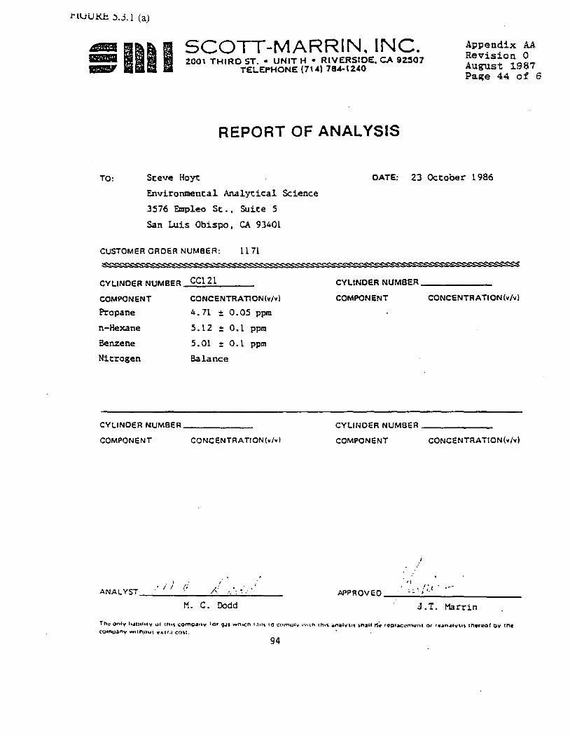
t'lvUKJ:. 5.3.l (a)
Appendix AA
51111 SCOTT-MARRIN. INC. Revision 0
2001 THIRO ST. • UNIT H • RIVERSIOE, CA 92:507 August 1987TELEPHONE (71'1 784-1240 Page 44 of 6
REPORT OF ANALYSIS
TO: Steve Hoy,: DATE: 23 October 1986
Environmental Analytical Science
3576 Empleo St., Suite 5
San Luis Obispo, CA 93401
CUSTOMER ORDER NUMBER: 11 71
CYLINDER NUMBER CC12l CYLINDER NUMBER ______
COMPONENT
Propane
n-Hexane
Benzene
Nitrogen
CONCENTRATION(v/vl
4. 71 :!: 0.05 ppm
S. l 2 :!: 0.1 ppm
5.01 :!: 0. l ppm
Balance
COMPONENT CONCENTRATION(v/vl
CYLINDER NUMBER _______ CYLINDER NUMBER _______
COMPONENT CONCENTRATION(•/•! COMPONENT CONCENTRATION(v/vl
/ , I
•• j /; t .APPROVED ___._._.._,_._________
H. C. Dodd J.T. Marrin
Th.: on6v l1.1,t>1t,1y of tt1,, comg.1,ny lnr gJ1 """n1cn 1.1,1, 10 cumulv ,•111n 1l"h1, 4naJv,1, \hall t1~ repl~c1:n,.:ni 0 ,. ri:.1,n,1ty1,,, 1r,-,,uof bv ~r,• c:u•nu~nv w11h.nu1 c.-.1,a en,:. •
94
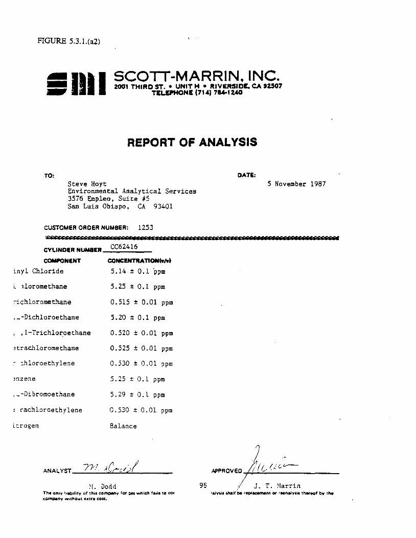
FIGURE 5.3.l.(a2)
SCOTT-MARRIN. INC. 2001 THIRD ST. • UNIT H • RIVERSIDE. CA 92507
TELDHONE (71~) 7M-IZ40
REPORT OF ANALYSIS
TO: DATE:
Steve Hoyt S November 1987 Environmental Analytical Services 3576 Empleo, Suite iS San Luis Obispo, CA 93401
CUSTOMER ORDER NUMBER: 1253 ssstt:eweeueeses tt c sec c c ecs1i't'>Qfttee C:N>t es r r re c CF Sf'S>N
24 15CYLINDER NUM8ER_c_c_5_ _ _ ___
COMPONENT CQNCDITRATIONCw/wt
inyl Chloride 5.14 ± 0.1 'ppm
i. 1loromethane 5.25 ± 0.1 ppm
~ichloromethane 0.515 ± 0.01 ppm
,_-Dichloroethane 5.20 ± 0.1 ppm
, ,1-Trichlo~oethane 0.520 ± 0.01 ppm
~trachloromethane 0.525 ± 0.01 ppm
~ :hloroethylene 0.530 ± 0.01 ppm
~nzene 5. 25 ± 0.1 ppm
,_-Dibromoethane s. 29 :!: 0.1 ppm
~ rachlorcethylene 0.530 ± 0.01 ppm
Ltrogen Balance
2 ,.71✓ ,1, (' • 1· 4.'1 (;I ,___ANALYST_____1~·•.C_c_·I_,_.______ APPROVED J (_, -C -
;I J.:! . Dodd 95 T. Marrin The on•v lletuhty of this company for Qa1 which ,.,,, ,a co, 1a,v1i1 INIJfbe r1p•acernen• or rNne&y1i1 t"'-eof by the co~nv wuhout ••tra con.

FIGURE 5.3.l (a3)
SIIII SCOTT-MARRIN. INC. 2001 THIRD ST. • UNIT H • RIVERSIDE. CA 92S07
TELEPHONE (7U) 78A-12'0
REPORT OF ANALYSIS
TO: DATE: Steve Hoyt 12 September 1988 Environmental Analytical Serv.ices 3576 Empleo Street, Ste. 5 San Luis Obispo, CA 93401
CUSTOMER ORDER NUMBER: 1367 ~~~~SSf'ff:f
CC68692CYLINDER NUMBER ______
COMPONENT CONCENTRATION(,/,1
Halocarbon-12 5.20 ~-;0.1 ppm
Haloc:1.rbon-ll 4.40 ± 0.1 ppm
1,1-Dichloroethylene 4.1!7 ± 0.1 ppm
1,1-Dichloroethane 5.05 :t 0.1 ppm
1,1,2-Tricr..loroethane 5. 2{J ± 0.1 ppm
!litrogen Balance
be repiacemen1 or runalyais thereof bY 11,eTh• ontv liability of this company for aa• which fails to co company withou1 extra cost. 96
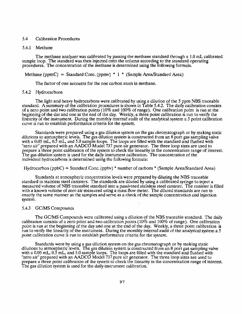
5.4 Calibration Procedures
5.4.1 Methane
The methane analyzer was calibrated by passing the methane standard through a 1.0 mL calibrated sample loop. The standard was then injected onto the column according to the standard operating procedures. The concentration of the methane is determined using the following formula.
Methane (ppmC) = Standard Cone. (ppmv) • 1 • (Sample Area/Standard Area)
The factor of one accounts for the one carbon atom in methane.
5.4.2 Hydrocarbons
The light and heavy hydrocarbons were calibrated by using a dilution of the 5 ppm NBS traceable standard. A summary of the calibration procedures is shown in Table 5.4.2. The daily calibration consists of a zero point and two calibration points (10% and 100% of range). One calibration point is run at the beginning of the dat and one at the end of the day. Weekly, a three point calibration is run to verify the linearity of the instrument. During the monthly internal audit of the analytical system a 5 point calibration curve is run to establish performance criteria for the system.
Standards were prepared using a gas dilution system on the gas chromatograph or by making static dilutions to atmospheric levels. The gas dilution system is constructed from an 8 port gas sampling valve with a 0.05 mL, 0.5 ml., and 5.0 sample loops. The loops are filled with the standard and flushed with "zero air" prepared with an AADCO Model 737 pure air generator. The three loop sizes are used to prepare a three point calibration of the system to check the linearity in the concentration range of interest. The gas dilution system is used for the daily instrument calibration. The concentration of the individual hydrocarbons is determined using the following formula:
Hydrocarbon (ppbC) =Standard Cone. (ppbv) • number of carbons• (Sample Area/Standard Area)
Standards at atmospheric concentration levels were prepared by diluting the NBS traceable standard in stainless steel canisters. The standards are diluted by using a calibrated syringe to inject a measured volume of NBS traceable standard into a passivated stainless steel canister. The canister is filled with a known volume of zero air measured using a mass flow meter. The diluted standards are run in exactly the same manner as the samples and serve as a check of the sample concentration and injection system.
5.4.3 GC/MS Compounds
The GC/MS Compounds were calibrated using a dilution of the NBS traceable standard. The daily calibration consists of a zero point and two calibration points (10% and 100% of range). One calibration point is run at the beginning of the day and one at the end of the day. Weekly, a three point calibration is run to verify the linearity of the instrument. During the monthly internal audit of the analytical system a 5 point calibration curve is run to establish performance criteria for the system.
Standards were by using a gas dilution system on the gas chromatograph or by making static dilutions to atmospheric levels. The gas dilution system is constructed from an 8 port gas sampling valve with a 0.05 mL, 0.5 ml., and 5.0 sample loops. The loops are filled with the standard and flushed with "zero air" prepared with an AADCO Model 737 pure air generator. The three loop sizes are used to prepare a three point calibration of the system to check the linearity in the concentration range of interest. The gas dilution system is used for the daily instrument calibration.
97
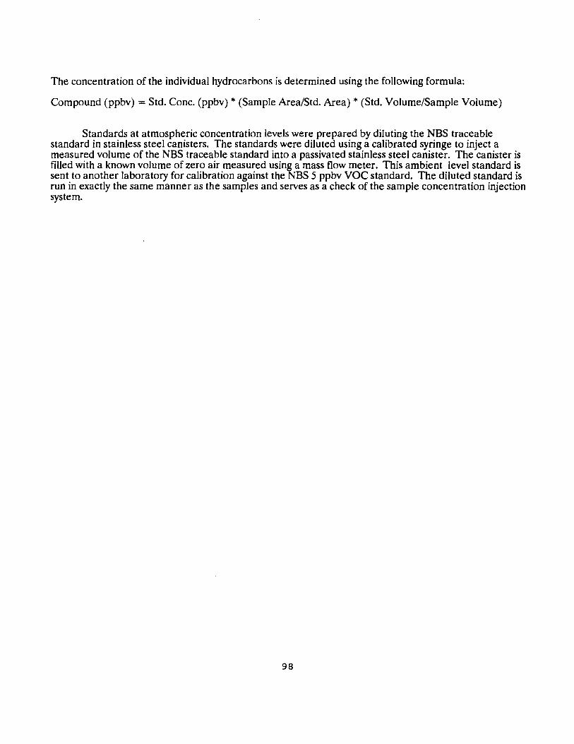
The concentration of the individual hydrocarbons is determined using the following formula:
Compound (ppbv) =Std.Cone. (ppbv) * (Sample Area/Std. Area)* (Std. Volume/Sample Volume)
Standards at atmospheric concentration levels were prepared by diluting the NBS traceable standard in stainless steel canisters. The standards were diluted using a calibrated syringe to inject a measured volume of the NBS traceable standard into a passivated stainless steel canister. The canister is filled with a known volume of zero air measured using a mass flow meter. This ambient level standard is sent to another laboratory for calibration against the NBS 5 ppbv VOC standard. The diluted standard is run in exactly the same manner as the samples and serves as a check of the sample concentration injection system.
98


![DOCUMENT RESUME ED 274 059 EA 018 819 - ERIC RESUME ED 274 059 EA 018 819 TITLE SEIS Data Profiles. Southeastern Educational Information System. [Third Issue]. INSTITUTION Southeastern](https://img.pdfslide.us/doc/110x75/5b19d4227f8b9a19258cfae9/document-resume-ed-274-059-ea-018-819-eric-resume-ed-274-059-ea-018-819-title.jpg)