Embed Size (px)
Citation preview
Contract # N00014-14-C-0020
Pilot-in-the-Loop CFD Method Development
Progress Report (CDRL A001)
Progress Report for Period: April 1, 2014 to May 20, 2014
PI: Joseph F. Horn
814-865-6434
Performing Organization:
The Pennsylvania State University
Department of Aerospace Engineering
231C Hammond Building
University Park, PA 16802
Attn: Joseph F. Horn
Phone: 814-865-6434, Fax: 814-865-7092
Email: [email protected]
Prepared under:
Contract Number N00014-14-C-0020
2012 Basic and Applied Research in Sea-Based Aviation
ONR #BAA12-SN-028
CDRL A001
DISTRIBUTION STATEMENT A: Distribution approved for public release; distribution is unlimited.
Report Documentation Page Form ApprovedOMB No. 0704-0188
Public reporting burden for the collection of information is estimated to average 1 hour per response, including the time for reviewing instructions, searching existing data sources, gathering andmaintaining the data needed, and completing and reviewing the collection of information. Send comments regarding this burden estimate or any other aspect of this collection of information,including suggestions for reducing this burden, to Washington Headquarters Services, Directorate for Information Operations and Reports, 1215 Jefferson Davis Highway, Suite 1204, ArlingtonVA 22202-4302. Respondents should be aware that notwithstanding any other provision of law, no person shall be subject to a penalty for failing to comply with a collection of information if itdoes not display a currently valid OMB control number.
1. REPORT DATE 16 JUN 2014 2. REPORT TYPE
3. DATES COVERED 01-04-2014 to 20-05-2014
4. TITLE AND SUBTITLE Pilot-in-the-Loop CFD Method Development
5a. CONTRACT NUMBER
5b. GRANT NUMBER
5c. PROGRAM ELEMENT NUMBER
6. AUTHOR(S) 5d. PROJECT NUMBER
5e. TASK NUMBER
5f. WORK UNIT NUMBER
7. PERFORMING ORGANIZATION NAME(S) AND ADDRESS(ES) The Pennsylvania State University,Department of AerospaceEngineering, 231C Hammond Building,University Park,PA,16802
8. PERFORMING ORGANIZATIONREPORT NUMBER
9. SPONSORING/MONITORING AGENCY NAME(S) AND ADDRESS(ES) 10. SPONSOR/MONITOR’S ACRONYM(S)
11. SPONSOR/MONITOR’S REPORT NUMBER(S)
12. DISTRIBUTION/AVAILABILITY STATEMENT Approved for public release; distribution unlimited
13. SUPPLEMENTARY NOTES
14. ABSTRACT
15. SUBJECT TERMS
16. SECURITY CLASSIFICATION OF: 17. LIMITATION OF ABSTRACT Same as
Report (SAR)
18. NUMBEROF PAGES
9
19a. NAME OFRESPONSIBLE PERSON
a. REPORT unclassified
b. ABSTRACT unclassified
c. THIS PAGE unclassified
Standard Form 298 (Rev. 8-98) Prescribed by ANSI Std Z39-18
Report Distribution per CDRLs for Contract No. N00014-14-C-0020
Section I: Project Summary
1. Overview of Project
This project is performed under the Office of Naval Research program on Basic and Applied Research in Sea-
Based Aviation (ONR BAA12-SN-0028). This project addresses the Sea Based Aviation (SBA) virtual dynamic
interface (VDI) research topic area “Fast, high-fidelity physics-based simulation of coupled aerodynamics of
moving ship and maneuvering rotorcraft”. The work is a collaborative effort between Penn State, NAVAIR, and
Combustion Research and Flow Technology (CRAFT-Tech). This document presents progress at Penn State
University.
All software supporting piloted simulations must run at real time speeds or faster. This requirement drives the
number of equations that can be solved and in turn the fidelity of supporting physics based models. For real-time
aircraft simulations, all aerodynamic related information for both the aircraft and the environment are
incorporated into the simulation by way of lookup tables. This approach decouples the aerodynamics of the
aircraft from the rest of its external environment. For example, ship airwakes are calculated using CFD solutions
without the presence of the helicopter main rotor. The gusts from the turbulent ship airwake are then re-played
into the aircraft aerodynamic model via look-up tables. For up and away simulations, this approach works well.
However, when an aircraft is flying very close to another body (i.e. a ship superstructure), aerodynamic coupling
can exist. The main rotor of the helicopter distorts the flow around the ship possibly resulting significant
differences in the disturbance on the helicopter. In such cases it is necessary to perform simultaneous
calculations of both the Navier-Stokes equations and the aircraft equations of motion in order to achieve a high
level of fidelity. This project will explore novel numerical modeling and computer hardware approaches with
the goal of real time, fully coupled CFD for virtual dynamic interface modeling & simulation.
Penn State is supporting the project through integration of their GENHEL-PSU simulation model of a utility
helicopter with CRAFT-Tech’s flow solvers. Penn State will provide their piloted simulation facility (the
VLRCOE rotorcraft simulator) for preliminary demonstrations of pilot-in-the-loop simulations. Finally, Penn
State will provide support for a final demonstration of the methods on the NAVAIR Manned Flight Simulator.
2. Activities this period
The flight dynamics software used in the project is the GENHEL-PSU simulation code. This code is a non-
linear dynamic model of a utility helicopter with a blade element rotor and finite state inflow model. The code
can easily operate in real-time simulations (i.e. real-time execution of the code is not a major factor). However,
the code needs to be set up to integrate with the fast flow solvers being developed at CRAFT-Tech. Efficient
integration and data exchange between the flight simulation (GENHEL-PSU) and the flow solver (CRUNCH)
will be critical to achieve fast execution speeds and eventually real-time.
During this period of report, the GENHEL-PSU code has been ported to a Linux platform in order to more
readily integrate with the CRUNCH flow solvers that will be used in coupled simulations. For initial testing,
one-way coupled simulations were set up. The one-way coupled airwake model had been developed in previous
efforts at Penn State [1], but had not been used in several years, so it needed to be debugged and verified with
the latest version of GENHEL-PSU. The airwake module was activated and verified with one-way coupled
LHA class ship airwake CFD results, produced by PUMA2 CFD code at Penn State[1].
Porting GENHEL-PSU to a Linux platform process started with choosing an appropriate Linux distribution and
compiler tools. CentOS Linux distribution has been chosen as a Linux platform and Intel Fortran and GNU GCC
compilers have been chosen as main compilation tools. The porting process required that most of the
communication libraries (required for the future tasks of this project) to be written partially or fully again. The
code was successfully ported and the outputs of the Linux version were verified against the GENHEL-PSU
Windows Version.
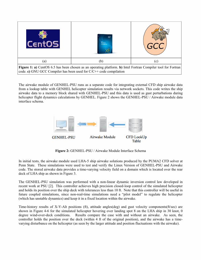
The airwake module of GENHEL-PSU runs as a separate code for integrating external CFD ship airwake data
from a lookup table with GENHEL helicopter simulation results via network sockets. This code writes the ship
airwake data to a memory block shared with GENHEL-PSU and this data is used as gust perturbations during
helicopter flight dynamics calculations by GENHEL. Figure 2 shows the GENHEL-PSU / Airwake module data
interface schema.
Figure 2: GENHEL-PSU / Airwake Module Interface Schema
In initial tests, the airwake module used LHA-5 ship airwake solutions produced by the PUMA2 CFD solver at
Penn State. These simulations were used to test and verify the Linux Version of GENHEL-PSU and Airwake
code. The stored airwake data provides a time-varying velocity field on a domain which is located over the rear
deck of LHA ship as shown in Figure 3.
The GENHEL-PSU simulation was performed with a non-linear dynamic inversion control law developed in
recent work at PSU [2]. This controller achieves high precision closed-loop control of the simulated helicopter
and holds its position over the ship deck with tolerances less than 10 ft. Note that this controller will be useful in
future coupled simulations, since non-real-time simulations need a “pilot model” to regulate the helicopter
(which has unstable dynamics) and keep it in a fixed location within the airwake.
Time-history results of X-Y-Alt positions (ft), attitude angles(deg) and gust velocity components(ft/sec) are
shown in Figure 4-6 for the simulated helicopter hovering over landing spot 8 on the LHA ship in 30 knot, 0
degree wind-over-deck conditions. Results compare the case with and without an airwake. As seen, the
controller holds the position over the deck (within 4 ft of the original position), and the airwake has a time-
varying disturbance on the helicopter (as seen by the larger attitude and position fluctuations with the airwake).
(a) (b) (c)
Figure 1: a) CentOS 6.5 has been chosen as an operating platform. b) Intel Fortran Compiler tool for Fortran
code. c) GNU GCC Compiler has been used for C/C++ code compilation
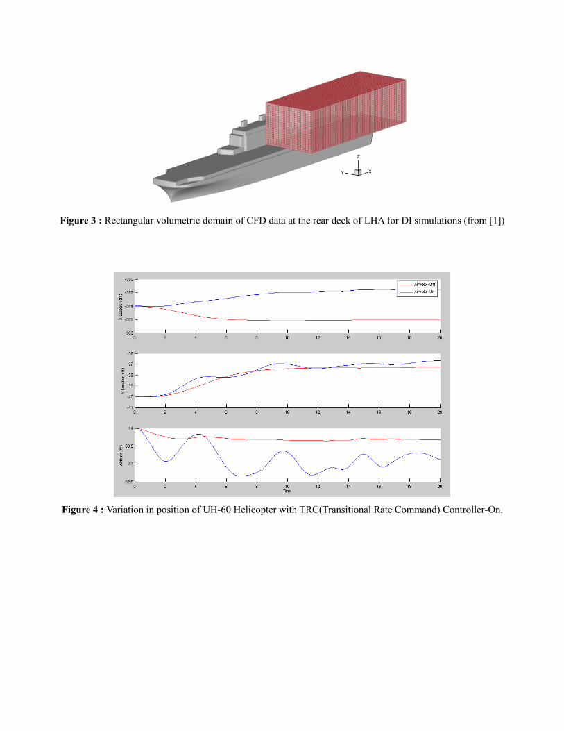
Figure 3 : Rectangular volumetric domain of CFD data at the rear deck of LHA for DI simulations (from [1])
Figure 4 : Variation in position of UH-60 Helicopter with TRC(Transitional Rate Command) Controller-On.
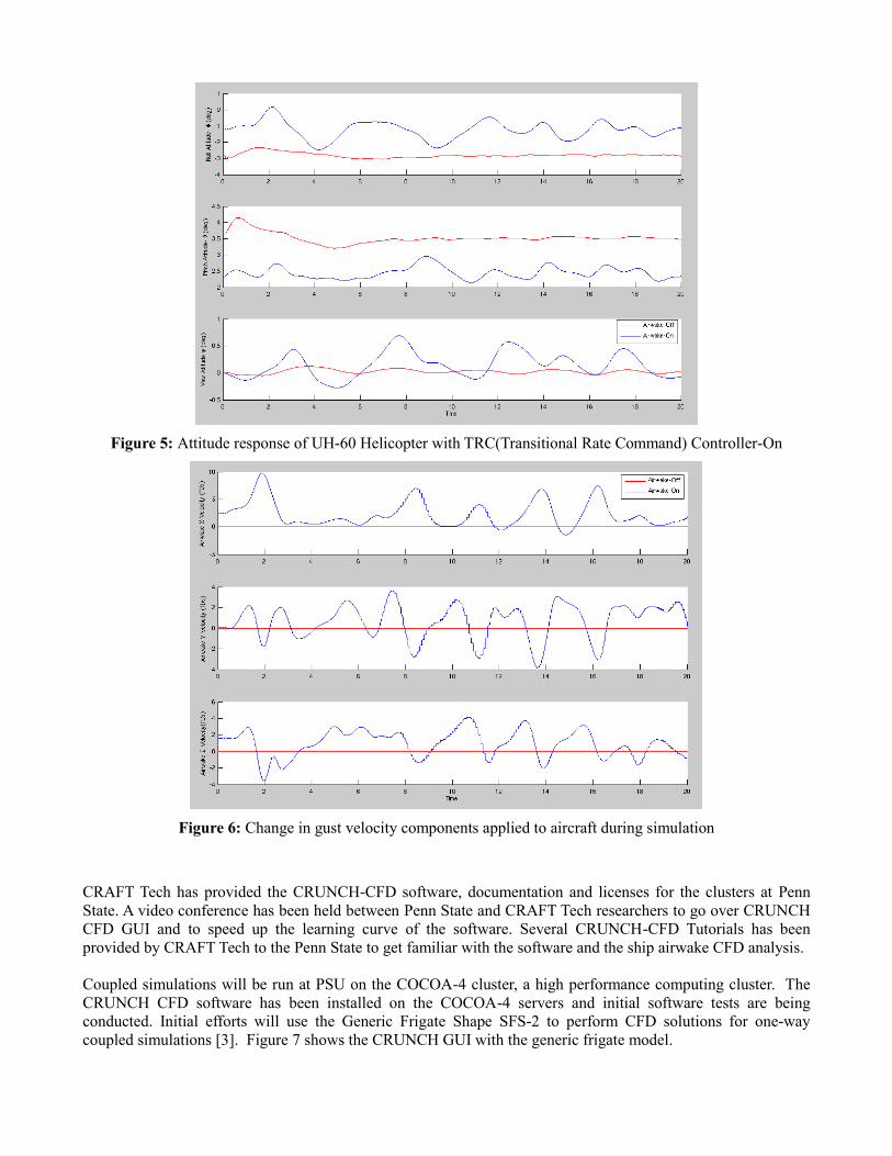
Figure 5: Attitude response of UH-60 Helicopter with TRC(Transitional Rate Command) Controller-On
Figure 6: Change in gust velocity components applied to aircraft during simulation
CRAFT Tech has provided the CRUNCH-CFD software, documentation and licenses for the clusters at Penn
State. A video conference has been held between Penn State and CRAFT Tech researchers to go over CRUNCH
CFD GUI and to speed up the learning curve of the software. Several CRUNCH-CFD Tutorials has been
provided by CRAFT Tech to the Penn State to get familiar with the software and the ship airwake CFD analysis.
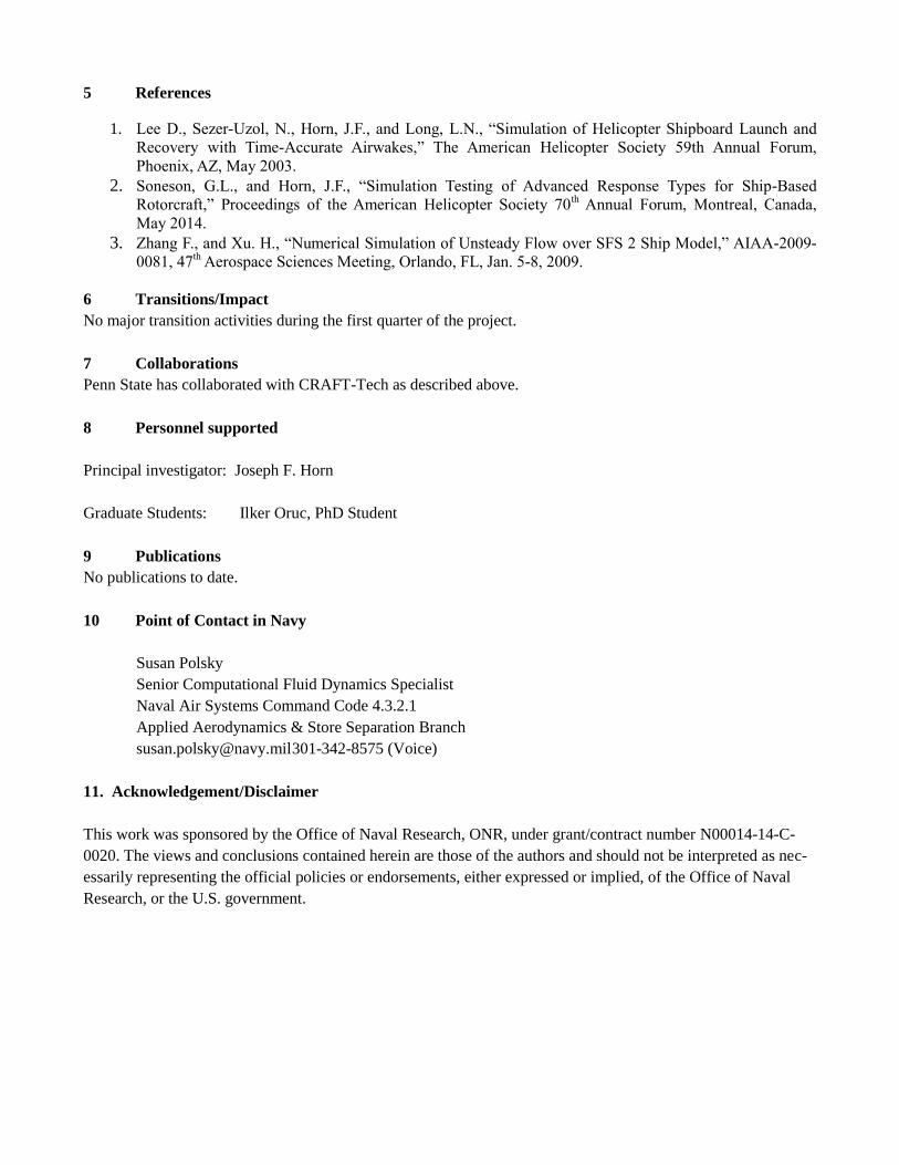
Coupled simulations will be run at PSU on the COCOA-4 cluster, a high performance computing cluster. The
CRUNCH CFD software has been installed on the COCOA-4 servers and initial software tests are being
conducted. Initial efforts will use the Generic Frigate Shape SFS-2 to perform CFD solutions for one-way
coupled simulations [3]. Figure 7 shows the CRUNCH GUI with the generic frigate model.
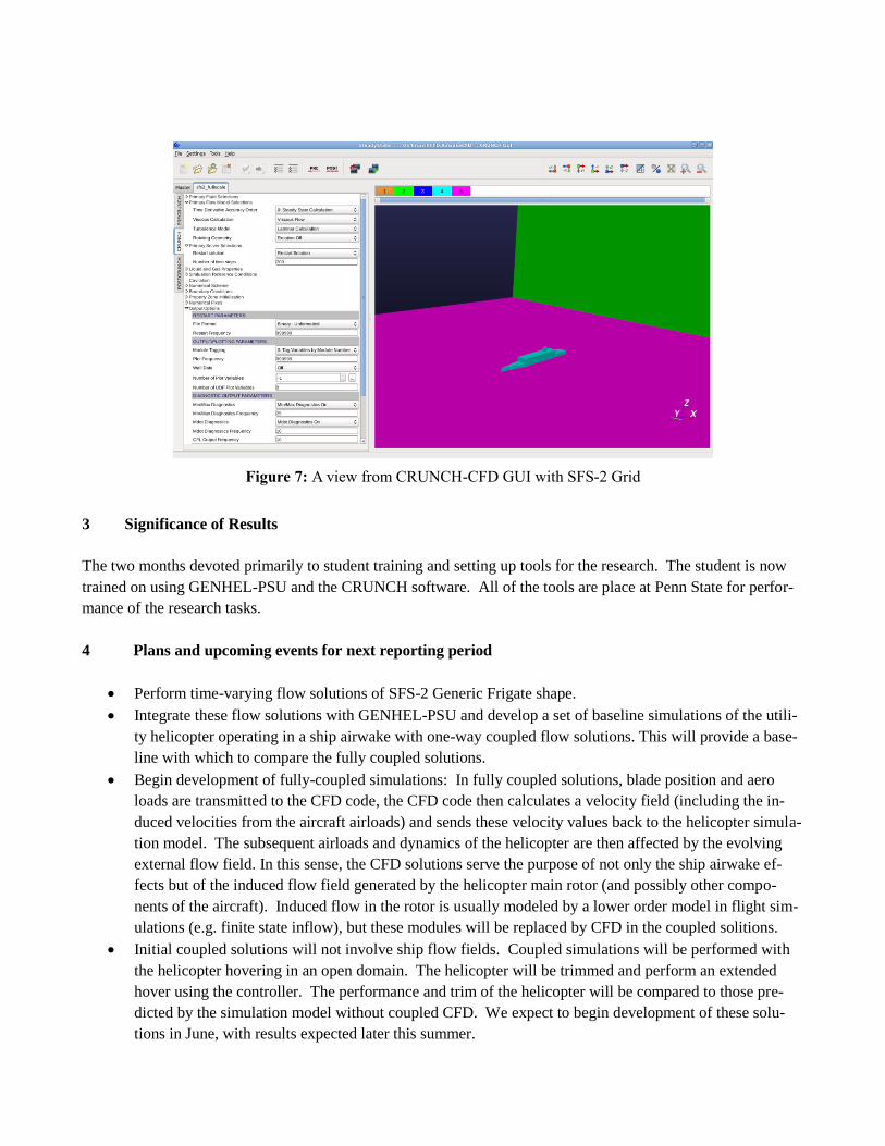
Figure 7: A view from CRUNCH-CFD GUI with SFS-2 Grid
3 Significance of Results
The two months devoted primarily to student training and setting up tools for the research. The student is now
trained on using GENHEL-PSU and the CRUNCH software. All of the tools are place at Penn State for perfor-
mance of the research tasks.
4 Plans and upcoming events for next reporting period
Perform time-varying flow solutions of SFS-2 Generic Frigate shape.
Integrate these flow solutions with GENHEL-PSU and develop a set of baseline simulations of the utili-
ty helicopter operating in a ship airwake with one-way coupled flow solutions. This will provide a base-
line with which to compare the fully coupled solutions.
Begin development of fully-coupled simulations: In fully coupled solutions, blade position and aero
loads are transmitted to the CFD code, the CFD code then calculates a velocity field (including the in-
duced velocities from the aircraft airloads) and sends these velocity values back to the helicopter simula-
tion model. The subsequent airloads and dynamics of the helicopter are then affected by the evolving
external flow field. In this sense, the CFD solutions serve the purpose of not only the ship airwake ef-
fects but of the induced flow field generated by the helicopter main rotor (and possibly other compo-
nents of the aircraft). Induced flow in the rotor is usually modeled by a lower order model in flight sim-
ulations (e.g. finite state inflow), but these modules will be replaced by CFD in the coupled solitions.
Initial coupled solutions will not involve ship flow fields. Coupled simulations will be performed with
the helicopter hovering in an open domain. The helicopter will be trimmed and perform an extended
hover using the controller. The performance and trim of the helicopter will be compared to those pre-
dicted by the simulation model without coupled CFD. We expect to begin development of these solu-
tions in June, with results expected later this summer.
5 References
1. Lee D., Sezer-Uzol, N., Horn, J.F., and Long, L.N., “Simulation of Helicopter Shipboard Launch and
Recovery with Time-Accurate Airwakes,” The American Helicopter Society 59th Annual Forum,
Phoenix, AZ, May 2003.
2. Soneson, G.L., and Horn, J.F., “Simulation Testing of Advanced Response Types for Ship-Based
Rotorcraft,” Proceedings of the American Helicopter Society 70th Annual Forum, Montreal, Canada,
May 2014. 3. Zhang F., and Xu. H., “Numerical Simulation of Unsteady Flow over SFS 2 Ship Model,” AIAA-2009-
0081, 47th Aerospace Sciences Meeting, Orlando, FL, Jan. 5-8, 2009.
6 Transitions/Impact
No major transition activities during the first quarter of the project.
7 Collaborations
Penn State has collaborated with CRAFT-Tech as described above.
8 Personnel supported
Principal investigator: Joseph F. Horn
Graduate Students: Ilker Oruc, PhD Student
9 Publications
No publications to date.
10 Point of Contact in Navy
Susan Polsky
Senior Computational Fluid Dynamics Specialist
Naval Air Systems Command Code 4.3.2.1
Applied Aerodynamics & Store Separation Branch
[email protected] 301-342-8575 (Voice)
11. Acknowledgement/Disclaimer
This work was sponsored by the Office of Naval Research, ONR, under grant/contract number N00014-14-C-
0020. The views and conclusions contained herein are those of the authors and should not be interpreted as nec-
essarily representing the official policies or endorsements, either expressed or implied, of the Office of Naval
Research, or the U.S. government.