Embed Size (px)
Citation preview
CONTRACT DOCUMENTS FOR THE CONSTRUCTION OF
Pump Station 022 Replacement
100% Submittal
City of Hampton
March 2018
Prepared by Woolpert, Inc.


Pump Station 022 Replacement
March 2018 TOC - 1
TABLE OF CONTENTS
PUMP STATION 022 REPLACEMENT
PAGE
I. TABLE OF CONTENTS ……………………………………………………….. TOC 1 - 2
II. SCOPE OF WORK……………………………….……………………………… SOW 1 - 2
III. TECHNICAL SPECIFICATIONS:
DIVISION 01 - GENERAL REQUIREMENTS
Section 01014 - Protection of Underground Utilities .......................................... 01014-1 – 01014-2
Section 01110 - Summary of Work ..................................................................... 01110-1 – 01110-4
Section 01330 - Submittal Procedures .............................................................. 01330-1 – 01330-12
Section 01575 - Temporary Environmental Controls ....................................... 01575-1 – 01575-12
Section 01781 - Operation and Maintenance Data .............................................. 01781-1 – 01781-4
DIVISION 02 - SITE WORK
Section 02060 – Building and Structure Demolition........................................... 02060-1 – 02060-4
Section 02100 - Clearing and Grubbing .............................................................. 02100-1 – 02100-4
Section 02315 - Excavation and Fill ................................................................. 02315-1 – 02315-10
Section 02610 - Underground Utility Pipe .......................................................... 02610-1 – 02610-4
Section 02741 - Bituminous Concrete Pavement ................................................ 02741-1 – 02741-4
Section 02821 – Chain Link Fencing & Gates .................................................... 02821-1 – 02821-6
DIVISION 03 CONCRETE
Section 03300 - Cast-In-Place Concrete ............................................................ 03300-1 – 03300-10
Section 03400 – Precast Concrete Wet Wells and Valve Vault ........................ 03400-1 – 03400-12
Section 03410 – Precast Structural Concrete Buildings .................................... 03410-1 – 03410-20
DIVISION 04 MASONRY – NOT USED
DIVISION 05 METALS
Section 05500 - Miscellaneous Metals and Fabrications .................................. 05500-1 – 05500-10
DIVISION 06 WOODS & PLASTICS – NOT USED
DIVISION 07 THERMAL & MOISTURE PROTECTION –NOT USED
DIVISION 08 DOORS AND WINDOWS
Section 08255 - Doors and Frames .................................................................... 08255-1 – 08255-8
Pump Station 022 Replacement
March 2018 TOC - 2
Section 08710 - Door Hardware .......................................................................... 08710-1 – 08710-6
DIVISION 09 FINISHES
Section 09900 - Paints and Coatings ................................................................. 09900-1 – 09900-18
DIVISION 10 SPECIALTIES
Section 10201 - Metal Wall Louvers ................................................................... 10201-1 – 10201-4
DIVISION 11 EQUIPMENT
Section 11330 – Non-Clog Submersible Centrifugal Pumps And Drives ........... 11330-1 – 11330-8
DIVISION 15 MECHANICAL
Section 15050 - Basic Mechanical Materials and Methods ................................ 15050-1 – 15050-4
Section 15060 - Interior Process Pipe, Fittings and Valves .............................. 15060-1 – 15060-10
Section 15190 - Hydrostatic Testing of Piping Systems ..................................... 15190-1 – 15190-2
Section 15200 – Heating and Ventilating Equipment ......................................... 15200-1 – 15200-6
Section 15210 - Domestic Water and Waste Piping............................................ 15210-1 – 15210-6
DIVISION 16 ELECTRICAL
Section 16010 – Electrical Basic Requirements ............................................... 16010-1 – 16010-10
Section 16020 – Utility Service and Service Entrance ....................................... 16020-1 – 16020-2
Section 16035 – Electrical Testing and Placing in Service ................................ 16035-1 – 16035-4
Section 16110 – Raceways ................................................................................. 16110-1 – 16110-6
Section 16120 – Wires and Cables ...................................................................... 16120-1 – 16120-8
Section 16130 – Electrical Boxes and Fittings ................................................... 16130-1 – 16130-6
Section 16135 – Wiring Devices ........................................................................ 16135-1 – 16135-4
Section 16190 – Supporting Devices ................................................................. 16190-1 – 16190-6
Section 16195 – Electrical Identification ........................................................... 16195-1 – 16195-4
Section 16410 – Pump Control Panel ............................................................... 16410-1 – 16410-30
Section 16440 – Disconnect Switches ................................................................ 16440-1 – 16440-4
Section 16450 – Grounding ................................................................................. 16450-1 – 16450-4
Section 16470 – Panelboards ............................................................................... 16470-1 – 16470-6
Section 16475 – Molded Case Circuit Breakers (MCCB) ................................. 16475-1 – 16475-2
Section 16482 – Motor Starters ........................................................................... 16482-1 – 16482-4
Section 16510 – LED Lighting Fixtures ............................................................. 16510-1 – 16510-4
Section 16690 – Variable Frequency Drive ........................................................ 16690-1 – 16690-8
Section 16920 – Programmable Logic Controller ............................................ 16920-1 – 16920-18
IV. APPENDICES:
Appendix A – Geotechnical Report
END OF TABLE OF CONTENTS
Pump Station 022 Replacement
March 2018 SOW-1
SCOPE OF WORK
SCOPE OF WORK:
The scope of the Work includes, but is not limited to, the following:
Construction of a submersible style wastewater pump station. The project includes a precast
concrete wet well, prefabricated building with all appurtenances, two submersible style sewage
pumps, controls, piping, flow meter and vault, emergency power generator connection and
associated site work.
Gravity sewer as shown on the drawings. Force main from the new pump station to connect to
existing 8” force main within the parcel. Construction access driveway from the asphalt alleyway
within the unnamed ingress/egress easement. New concrete driveway from the asphalt alleyway.
Demolition of the existing Pump Station 022 and removal of the existing 8” force main.
END OF SCOPE OF WORK

Pump Station 022 Replacement
March 2018 SOW-2
This Page Intentionally Left Blank
Pump Station 022 Replacement
March 2018 01014 - 1
SECTION 01014 - PROTECTION OF UNDERGROUND UTILITIES
1. GENERAL
1.1 DRAWINGS
Data regarding the presence, size, character and location of existing underground structures
has been shown on the contract drawings for informational purposes only. There is no
certainty of the accuracy of this information and the Contractor shall perform his own
investigations and survey to ascertain any and all obstructions. The location of underground
structures shown may not be wholly accurate and other obstructions than those shown may
be encountered. In general, house services, buried electric, gas, CATV, telephone, water and
sewer services to houses may not be shown. The Contractor shall assume that such services
exist and shall be responsible for protecting, maintaining and relocating such services or
having them replaced when damaged by his operations. The Contractor hereby expressly
agrees that neither the Owner nor the Engineer is responsible for the correctness or
sufficiency or absence of information regarding obstructions either revealed or not revealed
by the plans and that he shall have no claim for relief from any obligation or responsibility
under the Contract, in case the location, size or character of any pipe or other underground
structure is not as indicated or not shown on the plans. The Contractor shall not purchase
any materials nor initiate any work until he is completely satisfied that all underground
structures or utilities have been fully located and identified.
The Contractor should be aware that in some instances buried cables, gas lines, water lines,
etc., two inches and smaller in diameter may have to be excavated by hand and slightly
relocated to facilitate construction of the pipeline under this contract. This shall be
considered incidental to the work, and shall be performed at no additional cost to the Owner.
1.2 CHANGES IN THE WORK
Should the location of any pipe or conduit greater than 2 inches in diameter, pole, or other
structures, above or below the ground be such that in the opinion of the Owner or his
representative its removal, realignment, or change will be required due to work to be
performed under this Contract, the removal, realignment, or change will be done as a Change
Order, or will be done by the Owner of the obstructions, without cost to the Contractor. The
Contractor shall maintain at his own expense the structures until such removal and before
and after such realignment or change. The Contractor shall not be entitled to any claim for
damages or extra compensation because of the presence of said structure, or because of any
delay in the removal or relocation of the same.
Pump Station 022 Replacement
March 2018 01014 - 2
1.3 RESPONSIBILITY
The Contractor shall not interfere with any persons, firms or corporations, or with the Owner
or any agency having jurisdiction in protecting, removing, changing, or replacing their pipes,
conduits, poles, or other structures; but he shall suffer said persons, firms or corporations, or
the Owner, to take all such measures as they may deem necessary or advisable for the
purpose aforesaid, and the Contractor shall thereby be in no way relieved of any of his
responsibility under the Contract.
1.4 NOTIFICATION
The Contractor shall notify all owners of underground and overhead utilities at least 48 hours
prior to the commencement of excavation work where it is obvious or probable due to the
presence of nearby homes, markers and/or other types of structures that underground utilities
such as water, sewer, power, gas petroleum, telephone and the like exist near the site of
construction to ascertain the exact location of same so as not to interfere with or disrupt
service to the public.
1.5 COMPLIANCE
In addition to the requirements of these specifications, the Contractor is specifically
cautioned that he must comply with the requirements, including all revisions and
amendments thereto, of the Virginia "Underground Utility Damage Prevention Act" of 1979,
which became effective on July 1, 1980.
1.6 COORDINATION
Contractor is to contact and coordinate with "Miss Utility of Virginia" (811) when
excavating in the vicinity of underground utilities. Contractor shall also coordinate with
other contractors who may be working in the vicinity of the project site and installing
underground utilities as these utilities may not be marked by Miss Utility.
2. PRODUCTS
Not Used.
3. EXECUTION
Not Used.
END OF SECTION
Pump Station 022 Replacement
March 2018 01110-1
SECTION 01110 - SUMMARY OF WORK
1. GENERAL
1.1 WORK COVERED BY CONTRACT DOCUMENTS
1.1.1 Project Description
The project will replace the existing sewage pump station located at 279 W Gilbert
Street, Hampton, VA. Included is the replacement of Pump Station number 22,
associated site work for the new pump station, and the demolition of the existing pump
station. The project is comprised of the construction of a permanent single-story sanitary
sewage pumping station building. The pump station will provide services for the existing
service area. The pumps will convey flow from the gravity sewer collection system via a
new sanitary force main to discharge to the existing 8” force main.
1.1.2 Location
The majority of the work shall be located at the pump station site as shown on the
drawings.
1.1.3 Sequence of Construction
The following is a suggested sequence of construction:
1. PERFORM PRE-CONSTRUCTION CONFERENCE AND CONTRACTOR TO
OBTAIN ALL PERMITS.
2. CONTRACTOR TO PERFORM PRE-CONSTRUCTION SURVEY.
3. CITY TO INSTALL TEMPORARY EMERGENCY PUMP CONNECTION (EPC)
AND ESTABLISH BYPASSING PUMPING OPERATIONS FROM MH 022-0101.
4. CONTRACTOR TO INSTALL E&SC MEASURES FOR THE SITE AS INDICATED
ON SHEET C-2.
a. AN E&S INSPECTION IS REQUIRED AND MUST BE APPROVED PRIOR
TO THE CONTRACTOR OBTAINING ANY OTHER PERMITS.
5. CONTRACTOR TO REMOVE EXISTING 6' VYNL PRIVACY FENCE ALONG THE
NORTH SIDE OF THE PUMP STATION #022 SITE AS INDICATED ON SHEET C-
2.
6. CITY TO PROVIDE TEMPORARY PLUG FOR THE EFFLUENT 12” PIPE IN MH
022-0101.
a. CITY TO BEGIN CONTINUOUS BYPASS FROM MH 022-0101.
• THE CITY SHALL BE RESPONSIBLE FOR ALL MAINTENANCE
AND MONITORING OF FLOWS FOR THE DURATION OF
CONSTRUCTION ACTIVITIES.
b. CITY TO SHUT DOWN THE EXISTING PUMP STATION #022. THE
EXISTING STATION WILL REMAIN OUT OF OPERATION FOR THE
DURATION OF THE CONSTRUCTION PERIOD.
Pump Station 022 Replacement
March 2018 01110-2
7. CONTRACTOR TO ABANDON EXISTING PUMP STATION #022. SEE PS
ABANDONMENT NOTES ON SHEET C-2.
8. CONTRACTOR TO INSTALL SHEETING AND EXCAVATE.
9. CONTRACTOR TO INSTALL 8' DIAMETER PRECAST CONCRETE WET WELL.
10. CONTRACTOR TO REMOVE SHEETING.
11. CONTRACTOR TO INSTALL PROPOSED FORCE MAIN, MAGMETER & VALVE
VAULT, AND THE PERMANENT EPC.
12. CONTRACTOR TO PERFORM PRESSURE TEST ON FORCE MAIN. AFTER
SUCCSSFUL PRESSURE TEST, CONNECT TO THE EXISTING 6" GATE VALVE.
a. CONTRACTOR TO COORDINATE WITH THE CITY FOR THE
CONNECTION TO THE EXISTING 6" GATE VALVE.
b. CITY TO BYPASS FLOWS FROM MH 022-0101 TO THE PERMANENT
EPC.
13. CONTRACTOR TO INSTALL UNDERGROUND ELECTRICAL AND CONDUITS
AS INDICATED ON SHEET C-3.
14. CONTRACTOR TO INSTALL THE PROPOSED WATER SERVICE AS INDICATED
ON SHEET C-3. CONTRACTOR TO FIELD VERIFY LOCATION OF
CONNECTION TO THE EXISTING WATER SERVICE.
15. CONTRACTOR TO INSTALL PREFABRICATED PUMP STATION BUILDING
AND INSTALL STATION COMPONENTS.
16. CONTRACTOR TO PERFORM PS OPERATIONAL TESTS AS DIRECTED BY
CITY OF HAMPTON, WASTEWATER OPERATIONS PERSONNEL.
17. CONTRACTOR TO INSTALL THE PROPOSED 12" GRAVITY AS INDICATED ON
SHEET P-3 AND PROVIDE CONNECTION TO MH 022-0101. REMOVE
TEMPORARY PLUG.
a. CONTRACTOR TO COORDINATE WITH CITY PERSONEL PERFORMING
BYPASS OPERATIONS TO HOLD AND MONITOR FLOWS AS NEEDED
AT MH 022-0102, LOCATED IN THE EXISTING EASEMENT IN THE BACK
OF 306 ROANE DRIVE, AND MH 022-0104, LOCATED ON W GILBERT
STREET.
18. CITY TO REMOVE ALL BYPASSING ONCE PUMP STATION #022 IS ONLINE.
19. CONTRACTOR TO INSTALL CONCRETE DRIVE AND ADJUST MH 022-0101 TO
INDICATED GRADE.
20. CONTRACTOR TO GRADE & LANDSCAPE THE SITE AS INDICATED ON
SHEET C-4.
21. CONTRACTOR TO PERFORM SITE RESTORATION ACTIVITIES.
22. CONTRACTOR TO PERFORM POST-CONSTRUCTION CONDITION SURVEY.
23. CONTRACTOR TO REMOVE E&SC MEASURES.
a. A FINAL E&S INSPECTION IS REQUIRED AND MUST BE APPROVED
PRIOR TO PROJECT RELEASE.
Pump Station 022 Replacement
March 2018 01110-3
1.2 EXISTING WORK
The contractor shall endeavor to protect existing structures, piping and landscaping in
accordance with applicable provisions in the contract documents. In addition, the
contractor shall:
A. Remove or alter existing work in such a manner as to prevent injury or damage to
any portions of the existing work designated to remain.
B. Repair or replace portions of existing work, which have been altered during
construction operations to match existing or adjoining work, as approved by the
Owner. At the completion of operations, existing work shall be in a condition equal
to or better than that which existed before new work started.
1.3 LOCATION OF UNDERGROUND FACILITIES
Conform to Section 01014, "Protection of Underground Utilities." Obtain digging
permits prior to start of excavation. Scan the construction site with electromagnetic or
sonic equipment, and mark the surface of the ground where existing underground utilities
are discovered. Verify the elevations of existing piping, utilities, and any type of
underground obstruction not indicated or specified to be removed but indicated or
discovered during scanning in locations to be traversed by piping, ducts, and other work
to be installed. Verify elevations before installing new work closer than nearest manhole
or other structure at which an adjustment in grade can be made.
2. PRODUCTS
Not used.
3. EXECUTION
Not used.
END OF SECTION

Pump Station 022 Replacement
March 2018 01110-4
This Page Intentionally Left Blank
Pump Station 022 Replacement
March 2018 01330-1
SECTION 01330 -SUBMITTAL PROCEDURES
1. GENERAL
1.1 DEFINITIONS
1.1.1 Submittal
Shop drawings, product data, samples, and administrative submittals presented for review
and approval.
1.1.2 Types of Submittals
All submittals are classified as indicated in paragraph "Submittal Descriptions (SD)".
Submittals also are grouped as follows:
A. Shop drawings: As used in this section, drawings, schedules, diagrams, and other
data prepared specifically for this contract, by contractor or through contractor by
way of subcontractor, manufacturer, supplier, distributor, or other lower tier
contractor, to illustrate portion of work.
B. Product data: Preprinted material such as illustrations, standard schedules,
performance charts, instructions, brochures, diagrams, manufacturer's descriptive
literature, catalog data, and other data to illustrate portion of work, but not prepared
exclusively for this contract.
C. Samples: Physical examples of products, materials, equipment, assemblies, or
workmanship that are physically identical to portion of work, illustrating portion of
work or establishing standards for evaluating appearance of finished work or both.
D. Administrative submittals: Data presented for reviews and approval to ensure that
administrative requirements of project are adequately met but not to ensure directly
that work is in accordance with design concept and in compliance with contract
documents.
1.1.3 Submittal Descriptions (SD)
SD-01 Preconstruction Submittals
Certificates of insurance
Surety bonds
List of proposed subcontractors
List of proposed products
Construction Progress Schedule
Submittal schedule
Schedule of values
Pump Station 022 Replacement
March 2018 01330-2
Health and safety plan
Work plan
Quality control plan
Environmental protection plan
SD-02 Shop Drawings
Drawings, diagrams and schedules specifically prepared to illustrate some portion of the
work.
Diagrams and instructions from a manufacturer or fabricator for use in producing the
product and as aids to the contractor for integrating the product or system into the project.
Drawings prepared by or for the contractor to show how multiple systems and
interdisciplinary work will be coordinated.
SD-03 Product Data
Catalog cuts, illustrations, schedules, diagrams, performance charts, instructions and
brochures illustrating size, physical appearance and other characteristics of materials or
equipment for some portion of the work.
Samples of warranty language when the contract requires extended product warranties.
SD-04 Samples
Physical examples of materials, equipment or workmanship that illustrate functional and
aesthetic characteristics of a material or product and establish standards by which the
work can be judged.
Color samples from the manufacturer's standard line (or custom color samples if
specified) to be used in selecting or approving colors for the project.
Field samples and mock-ups constructed on the project site establish standards by which
the ensuring work can be judged. Includes assemblies or portions of assemblies which
are to be incorporated into the project and those which will be removed at conclusion of
the work.
SD-05 Design Data
Calculations, mix designs, analyses, or other data pertaining to a part of work.
Pump Station 022 Replacement
March 2018 01330-3
SD-06 Test Reports
Report signed by authorized official of testing laboratory that a material, product or
system identical to the material, product or system to be provided has been tested in
accord with specified requirements. (Testing must have been within three years of date
of contract award for the project.)
Report which includes findings of a test required to be performed by the contractor on an
actual portion of the work or prototype prepared for the project before shipment to job
site.
Report which includes finding of a test made at the job site or on sample taken from the
job site, on portion of work during or after installation.
Investigation reports
Daily checklists
Final acceptance test and operational test procedure
SD-07 Certificates
Statements signed by responsible officials of manufacturer of product, system or material
attesting that product, system or material meets specification requirements. Must be
dated after award of project contract and clearly name the project.
Document required of Contractor, or of a supplier, installer or subcontractor through
Contractor, the purpose of which is to further quality of orderly progression of a portion
of the work by documenting procedures, acceptability of methods or personnel
qualifications.
Confined space entry permits.
SD-08 Manufacturer's Instructions
Preprinted material describing installation of a product, system or material, including
special notices and Material Safety Data sheets concerning impedances, hazards and
safety precautions.
SD-09 Manufacturer's Field Reports
Documentation of the testing and verification actions taken by manufacturer's
representative to confirm compliance with manufacturer's standards or instructions.
Factory test reports.
Pump Station 022 Replacement
March 2018 01330-4
SD-10 Operation and Maintenance Data
Data intended to be incorporated in operations and maintenance manuals. Comply with
section 01781, Operations and Maintenance Data, and with specific sections of the
specifications.
SD-11 Closeout Submittals
Documentation to record compliance with technical or administrative requirements or to
establish an administrative mechanism.
As-built drawings
Special warranties
Posted operating instructions
Training plan
1.1.4 Approving Authority
Person authorized to approve submittal.
1.1.5 Work
As used in this section, on- and off-site construction required by contract documents,
including labor necessary to produce construction and materials, products, equipment,
and systems incorporated or to be incorporated in such construction.
1.2 SUBMITTALS
Submit the following in accordance with the requirements of this section.
SD-11 Closeout Submittals
Submittal register
1.3 USE OF SUBMITTAL REGISTER
Prepare and maintain submittal register, as the work progresses.
1.3.1 Submittal Register
Submit submittal register periodically throughout the project. Verify that all submittals
required for project are listed and add missing submittals. Complete the following on the
register:
Pump Station 022 Replacement
March 2018 01330-5
Specification Section: Specification number requiring the submittal.
Contractor Approval Date: Date contractor needs approval of submittal.
Transmittal Number: Contractor assigned list of consecutive numbers.
List date of submittal transmission.
List date approval received.
List date of submittal receipt.
List date returned to contractor.
1.3.2 Contractor Action Code and Action Code
Entries used will be as follows (others may be prescribed by Transmittal Form):
NR - Not Received
AN - Approved as noted
A – Approved as submitted
R - Rejected
RR - Revise and Resubmit
SI – Submit Specified Item
1.3.3 Copies Delivered to the Engineer
Deliver one copy of submitted register updated by Contractor to Engineer with each
invoice request.
1.4 PROCEDURES FOR SUBMITTALS
1.4.1 Reviewing, Certifying, Approving Authority
Contractor shall be responsible for reviewing and certifying that submittals are in
compliance with contract requirements. Approving authority on submittals is Engineer or
his representative unless otherwise specified for a specific submittal.

Pump Station 022 Replacement
March 2018 01330-6
1.4.2 Constraints
A. Submittals listed or specified in this contract shall conform to provisions of this
section, unless explicitly stated otherwise.
B. Submittals shall be complete for each definable feature of work; components of
definable feature interrelated as a system shall be submitted at same time.
C. When acceptability of a submittal is dependent on conditions, items, or materials
included in separate subsequent submittals, submittal will be returned without
review.
D. Approval of a separate material, product, or component does not imply approval of
assembly in which item functions.
1.4.3 Scheduling
A. Coordinate scheduling, sequencing, preparing and processing of submittals with
performance of work so that work will not be delayed by submittal processing.
Allow for potential requirements to resubmit.
B. Except as specified otherwise, allow review period, beginning with receipt by
approving authority, which includes at least 15 working days for submittals for
approval. Period of review for submittals begins when Engineer or his
representative receives submittal from the contractor. Period of review for each
resubmittal is the same as for initial submittal.
C. Certain submittals, such as the Emergency Generator, Odor Control Systems, Pump
Station Control Panels, Pumps, Operation and Maintenance Manuals, etc., require
additional review and approval from the locality. Contractor shall allow an
additional 10 working days for review of these submittals. Contractor shall request
the identity of these particular submittals upon submission of the Submittal Register.
1.4.4 Variations
Variations from contract requirements require Engineer approval and will be considered
where advantageous to Owner.
1.4.4.1 Considering Variations
Discussion with the Engineer prior to submission will help ensure functional and quality
requirements are met and minimize rejections and resubmittals.

Pump Station 022 Replacement
March 2018 01330-7
1.4.4.2 Proposing Variations
When proposing variation, deliver written request to the Engineer, with documentation of
the nature and features of the variation and why the variation is desirable and beneficial
to the City. In addition to documentation required for variation, include the submittals
required for the item. Clearly mark the proposed variation in all documentation.
1.4.4.3 Warranting That Variation Are Compatible
When delivering a variation for approval, contractor warrants that this contract has been
reviewed to establish that the variation, if incorporated, will be compatible with other
elements of work.
1.4.4.4 Review Schedule Is Modified
In addition to normal submittal review period, a period of 10 working days will be
allowed for consideration by the Engineer of submittals with variations.
1.4.5 Contractor's Responsibilities
A. Determine and verify field measurements, materials, field construction criteria;
review each submittal; and check and coordinate each submittal with requirements
of the work and contract documents.
B. Transmit submittals to Engineer or his representative in accordance with schedule
on approved Submittal Register, and to prevent delays in the work, delays to
Engineer, or delays to separate contractors.
C. Advise Engineer of variation, as required by paragraph entitled "Variations."
D. Correct and resubmit submittal as directed by approving authority. When
resubmitting disapproved transmittals or transmittals noted for resubmittal, the
contractor shall provide copy of that previously submitted transmittal including all
reviewer comments for use by approving authority. Direct specific attention in
writing or on resubmitted submittal, to revisions not requested by approving
authority on previous submissions.
E. Furnish additional copies of submittal when requested by Engineer, to a limit of 5
copies per submittal.
F. Complete work that must be accomplished as basis of a submittal in time to allow
submittal to occur as scheduled.
G. Ensure no work has begun until submittals for that work have been returned as
"approved," or "approved as noted", except to the extent that a portion of work must
be accomplished as basis of submittal.
Pump Station 022 Replacement
March 2018 01330-8
1.4.6 Engineer's Responsibilities
When approving authority is Engineer or his representative, the Engineer will:
A. Note date on which submittal was received from Contractor, on each submittal for
which the Engineer is approving authority.
B. Review submittals for approval within scheduling period specified and only for
conformance with project design concepts and compliance with contract documents.
C. Identify returned submittals with one of the actions defined in paragraph entitled
"Actions Possible" and with markings appropriate for action indicated.
1.4.7 Actions Possible
Submittals will be returned with one of the following notations:
A. Submittals marked "not reviewed" will indicate submittal has been previously
reviewed and approved, is not required, does not have evidence of being reviewed
and approved by contractor, or is not complete. A submittal marked "not reviewed"
will be returned with an explanation of the reason it is not reviewed. Resubmit
submittals returned for lack of review by contractor or for being incomplete, with
appropriate action, coordination, or change.
B. Submittals marked "approved" or "approved as submitted" authorize contractor to
proceed with work covered.
C. Submittals marked "approved as noted" authorize contractor to proceed with work
as noted provided contractor takes no exception to the notations.
D. Submittals marked "revise and resubmit" or "rejected" indicate submittal is
incomplete or does not comply with design concept or requirements of the contract
documents and shall be resubmitted with appropriate changes. No work shall
proceed for this item until resubmittal is approved.
E. Submittals marked “submit specified item” authorize contractor to proceed with the
portions of the work except for the item noted by the approving authority. The
specified item shall be resubmitted with appropriate changes. No work shall proceed
for this item until resubmittal is approved.
Pump Station 022 Replacement
March 2018 01330-9
1.5 FORMAT OF SUBMITTALS
1.5.1 Transmittal Form
Transmit each submittal, except sample installations and sample panels, to office of
approving authority. Transmit submittals with transmittal form prescribed by Engineer
and standard for project. The transmittal form shall identify contractor, indicate date of
submittal, and include information prescribed by transmittal form and required in
paragraph entitled "Identifying Submittals." Process transmittal forms to record actions
regarding sample panels and sample installations.
1.5.2 Identifying Submittals
Identify submittals, except sample panel and sample installation, with the following
information permanently adhered to or noted on each separate component of each
submittal and noted on transmittal form. Mark each copy of each submittal identically,
with the following:
A. Project title and location.
B. Construction contract number.
C. Section number of the specification section by which submittal is required.
D. Submittal description (SD) number of each component of submittal.
E. When a resubmission, alphabetic suffix on submittal description, for example, SD-
10A, to indicate resubmission.
F. Name, address, and telephone number of subcontractor, supplier, manufacturer and
any other second tier contractor associated with submittal.
G. Product identification and location in project.
1.5.3 Format for Product Data
A. Present product data submittals for each section as a complete, bound volume.
Include table of contents, listing page and catalog item numbers for product data.
B. Indicate, by prominent notation, each product which is being submitted; indicate
specification section number and paragraph number to which it pertains.
C. Supplement product data with material prepared for project to satisfy submittal
requirements for which product data does not exist. Identify this material as
developed specifically for project.
Pump Station 022 Replacement
March 2018 01330-10
1.5.4 Format for Shop Drawings
A. Shop drawings shall not be less than 8 1/2 by 11 inches nor more than 30 x 42
inches.
B. Present 8 1/2 x 11 inches sized shop drawings as part of the bound volume for
submittals required by section. Present larger drawings in sets.
C. Include on each drawing the drawing title, number, date, and revision numbers and
dates, in addition to information required in paragraph entitled "Identifying
Submittals."
D. Dimension drawings, except diagrams and schematic drawings; prepare drawings
demonstrating interface with other trades to scale. Identify materials and products
for work shown.
1.5.5 Format of Samples
A. Furnish samples in sizes below, unless otherwise specified or unless the
manufacturer has prepackaged samples of approximately same size as specified:
(1) Sample of Equipment or Device: Full size.
(2) Sample of Materials Less Than 2 by 3 inches: Built up to 8 1/2 by 11 inches.
(3) Sample of Materials Exceeding 8 1/2 by 11 inches: Cut down to 8 1/2 by 11
inches and adequate to indicate color, texture, and material variations.
(4) Sample of Linear Devices or Materials: 10 inch length or length to be
supplied, if less than 10 inches. Examples of linear devices or materials are
conduit and handrails.
(5) Sample of Non-Solid Materials: Pint. Examples of non-solid materials are
sand and paint.
(6) Color Selection Samples: 2 by 4 inches.
(7) Sample Panel: 4 by 4 feet.
(8) Sample Installation: 100 square feet.
B. Samples Showing Range of Variation: Where variations are unavoidable due to
nature of the materials, submit sets of samples of not less than three units showing
extremes and middle of range.

Pump Station 022 Replacement
March 2018 01330-11
C. Reusable Samples: Incorporate returned samples into work only if so specified or
indicated. Incorporated samples shall be in undamaged condition at time of use.
D. Recording of Sample Installation: Note and preserve the notation of area
constituting sample installation but remove notation at final clean up of project.
E. When color, texture, or pattern is specified by naming a particular manufacturer and
style, include one sample of that manufacturer and style, for comparison.
1.5.6 Format of Administrative Submittals
A. When submittal includes a document which is to be used in project or become part
of project record, other than as a submittal, do not apply contractor's approval stamp
to document, but to a separate sheet accompanying document.
B. Operation and Maintenance Manual Data: Submit in accordance with Section
01781, "Operation and Maintenance Data.".
1.6 QUANTITY OF SUBMITTALS
1.6.1 Number of Copies of Product Data
A. Submit four copies of submittals of product data requiring review and approval in
addition to those submittals required for contractor’s records and suppliers.
B. If Contractor elects to provide submittals electronically (via internet e-mail or FTP),
submit in Adobe PDF, TIFF, JPEG, or other acceptable digital format approved by
the Engineer. Submittals provided electronically will be returned electronically in
PDF, JPEG, or TIFF format, as appropriate. Contractor shall assume responsibility
for printing multiple copies of returned submittals for contractor’s records and
suppliers. Engineer shall forward appropriate copies to the developer and the
locality.
1.6.2 Number of Copies of Shop Drawings
Submit shop drawings in compliance with quantity requirements specified for product
data.
1.6.3 Number of Samples
A. Submit two samples, or two sets of samples showing range of variation, of each
required item. One approved sample or set of samples will be retained by approving
authority and one will be returned to contractor.
B. Submit one sample panel. Include components listed in technical section or as
directed.

Pump Station 022 Replacement
March 2018 01330-12
C. Submit one sample installation, where directed.
D. Submit one sample of non-solid materials.
1.6.4 Number of Copies of Administrative Submittals
A. Unless otherwise specified, submit administrative submittals compliance with
quantity requirements specified for product data.
B. Submit administrative submittals required under "SD-19 Operation and
Maintenance Manuals" to conform to Section 01781, "Operation and Maintenance
Data."
2. PRODUCTS
Not used.
3. EXECUTION
Not used.
END OF SECTION
Pump Station 022 Replacement
March 2018 01575-1
SECTION 01575 -TEMPORARY ENVIRONMENTAL CONTROLS
1. GENERAL
1.1 REFERENCES
The publications listed below form a part of this specification to the extent referenced.
The publications are referred to in the text by the basic designation only. The referenced
publications shall be the current effective edition.
CODE OF FEDERAL REGULATIONS (CFR)
40 CFR 122.26 EPA National Pollutant Discharge Elimination System
Permit Regulations
40 CFR 241 Guidelines for Disposal of Solid Waste
40 CFR 243 Guidelines for the Storage and Collection of Residential,
Commercial, and Institutional Solid Waste
40 CFR 258 Subtitle D Landfill Requirements
40 CFR 261 Identification and Listing of Hazardous Waste
40 CFR 262 Generators of Hazardous Waste
40 CFR 263 Transporters of Hazardous Waste
40 CFR 264 Owners and Operators of Hazardous Waste Treatment,
Storage, and Disposal Facilities
40 CFR 265 Interim Status Standard for Owners and Operators of
Hazardous Waste Treatment, Storage, and Disposal
Facilities
40 CFR 266 Management of Specific Hazardous Wastes and Specific
Types of Hazardous Waste Management Facilities
40 CFR 268 Land Disposal Restrictions
40 CFR 279 Used Oil Regulations
40 CFR 300 National Oil and Hazardous Substances Pollution
Contingency Plan
49 CFR 173 Shipments and Packagings
Pump Station 022 Replacement
March 2018 01575-2
ENVIRONMENTAL PROTECTION AGENCY (EPA)
EPA 832-R-92-005 Storm Water Management for Construction Activities
VIRGINIA DEPARTMENT OF CONSERVATION AND RECREATION (DCR)
VESCH Virginia Erosion and Sediment Control Handbook
1.2 DEFINITIONS
1.2.1 Sediment
Soil and other debris that have eroded and have been transported by runoff water or wind.
1.2.2 Solid Waste
Garbage, refuse, debris, sludge, or other discharged material (except hazardous waste as
defined in paragraph entitled "Hazardous Waste" or hazardous debris as defined in
paragraph entitled "Hazardous Debris"), including solid, liquid, semisolid, or contained
gaseous materials resulting from domestic, industrial, commercial, mining, or agricultural
operations. Material not regulated as solid waste are: nuclear source or byproduct
materials regulated under the Federal Atomic Energy Act of 1954 as amended; suspended
or dissolved materials in domestic sewage effluent or irrigation return flows, or other
regulated point source discharges; regulated air emissions; and fluids or wastes associated
with natural gas or crude oil exploration or production.
A. Green waste: The vegetative matter from landscaping, land clearing and grubbing,
including, but not limited to, grass, bushes, scrubs, small trees and saplings, tree
stumps and plant roots. Marketable trees, grasses and plants that are indicated to
remain, be re-located, or be re-used are not included.
B. Surplus soil: Existing soil that is in excess of what is required for this work,
including aggregates intended, but not used, for on-site mixing of concrete, mortars
and paving. Contaminated soil meeting the definition of hazardous material or
hazardous waste is not included.
C. Inert construction and demolition debris: Broken or removed concrete, masonry,
and rock asphalt paving; ceramics; roofing paper and shingles. Inert materials may
be reinforced with or contain ferrous wire, rods, accessories and weldments.
D. Wood: Dimension and non-dimension lumber, plywood, chipboard, hardboard.
Treated and/or painted wood that meets the definition of lead contaminated or lead
based contaminated paint is not included.
Pump Station 022 Replacement
March 2018 01575-3
E. Scrap metal: Scrap and excess ferrous and non-ferrous metals such as re-enforcing
steel, structural shapes, pipe and wire that are recovered or collected and disposed of
as scrap. Scrap metal meeting the definition of hazardous material or hazardous
waste is not included.
F. Paint cans: Metal cans that are empty of paints, solvents, thinners and adhesives. If
permitted by the paint can label, a thin dry film may remain in the can.
G. Recyclables: Materials, equipment and assemblies such as doors, windows, door
and window frames, plumbing fixtures, glazing and mirrors that are recovered and
sold as recyclable. Metal meeting the definition of lead contaminated or lead based
paint contaminated may not be included as recyclable if sold to a scrap metal
company. Paint cans may not be included as recyclable if sold to a scrap metal
company.
1.2.3 Debris
Non-hazardous solid material generated during the construction, demolition, or
renovation of a structure which exceeds 2.5 inch particle size that is: a manufactured
object; plant or animal matter; or natural geologic material (e.g. cobbles and boulders). A
mixture of debris and other material such as soil or sludge is also subject to regulation as
debris if the mixture is comprised primarily of debris by volume, based on visual
inspection.
1.2.4 Hazardous Debris
As defined in paragraph entitled "Debris" of this section, debris that contains listed
hazardous waste (either on the debris surface, or in its interstices, such as pore structure)
per 40 CFR 261; or debris that exhibits a characteristic of hazardous waste per 40 CFR
261.
1.2.5 Chemical Wastes
This includes salts, acids, alkalies, herbicides, pesticides, and organic chemicals.
1.2.6 Garbage
Refuse and scraps resulting from preparation, cooking, dispensing, and consumption of
food.
1.2.7 Hazardous Waste
Hazardous waste as defined in 40 CFR 261 or as defined by applicable State and local
regulations.
Pump Station 022 Replacement
March 2018 01575-4
1.2.8 Oily Waste
Petroleum products and bituminous materials.
1.3 REPORTS
1.3.1 Preconstruction Survey
Perform a preconstruction survey of the project site, and take photographs showing
existing environmental conditions in and adjacent to the site. A report shall be made
available upon request by the Engineer or Owner.
1.3.2 Disposal Documentation for Hazardous and Regulated Waste
Submit a copy, upon request by the Engineer or Owner, of the applicable EPA and State
permit(s), manifest(s), or license(s) for transportation, treatment, storage, and disposal of
hazardous and regulated waste by permitted facilities.
1.3.3 Regulatory Notification
The Contractor is responsible for all regulatory notification requirements in accordance
with Federal, State and local regulations. The Contractor shall forward copies to the
Engineer prior to commencement of work activities.
1.4 ENVIRONMENTAL PROTECTION REQUIREMENTS
Provide and maintain, during the life of the contract, environmental protection as defined.
Plan for and provide environmental protective measures to control pollution that develops
during normal construction practice. Plan for and provide environmental protective
measures required to correct conditions that develop during the construction of
permanent or temporary environmental features associated with the project. Comply with
Federal, State, and local regulations pertaining to the environment, including water, air,
solid waste, hazardous waste and substances, oily substances, and noise pollution.
1.4.1 Licenses and Permits
The contractor is responsible for acquiring and maintaining all licenses, permits, and
approvals necessary for this project as noted in the Contract Documents. Upon request,
provide copies to the Engineer or Owner. Post all permits in a weatherproofed enclosure
visible from the entrance to the site a minimum of four feet off the ground.
Pump Station 022 Replacement
March 2018 01575-5
1.4.1.1 Storm Water Pollution Prevention Plan (SWPPP)
A Storm Water Pollution Prevention Plan (SWPPP) must be maintained at the site by the
Contractor. The Engineer has prepared a SWPPP for the Contractor’s use. The
Contractor may submit, for review and approval, an alternate plan. A guide for preparing
the SWPPP can be found at the U.S. Environmental Protection Agency (EPA) website:
http://cfpub.epa.gov/npdes/stormwater/swppp.cfm. It describes the SWPPP development
process and provides helpful guidance and tips for developing and implementing an
effective SWPPP. In addition, the guide provides customizable SWPPP templates and a
sample inspection report, in Microsoft Word format.
1.4.1.2 Responsible Land Disturber (RLD)
The Contractor shall supply the name and registration number of the “Responsible Land
Disturber” to the Owner prior to construction.
1.4.1.3 Land Disturbing Permit
Contractor shall be responsible for acquiring a Land Disturbing Permit from the local
authority.
1.4.1.4 Right of Way Land Use Permit
The Contractor shall pay for and acquire any right of way land use permits required by
the local authority or VDOT. The Contractor will be responsible for completing the work
according to the terms of the permit. The Contractor will post the bond for the permit.
The Contractor's performance bond will cover his performance of all work in the project,
including compliance with right of way regulations. Where the word "Permittee" appears
in the permit and in special provisions tied to the permit, it shall be the responsibility of
the Contractor to meet these requirements.
1.4.1.5 Building Permits
Contractor is responsible for obtaining all building permits (including structural,
mechanical, electrical, and plumbing) required by the local authority. Contractor shall
coordinate all required inspections to obtain a Certificate of Occupancy prior to project
completion.
1.4.2 Contractor Liabilities for Environmental Protection
The Contractor is advised that this project and the Owner are subject to Federal, State,
and local regulatory agency inspections to review compliance with environmental laws
and regulations. The Contractor shall fully cooperate with any representative from any
Federal, State, or local regulatory agency who may visit the job site and shall provide
immediate notification to the Owner, who shall accompany them on any subsequent site
inspections. The Contractor shall complete, maintain, and make available to the owner or
regulatory agency personnel all documentation relating to environmental compliance

Pump Station 022 Replacement
March 2018 01575-6
under applicable Federal, State and local laws and regulations. The Contractor shall
immediately notify the Engineer and Owner if a Notice of Violation (NOV) is issued to
the Contractor.
The Contractor shall be responsible for all damages to persons or property resulting from
Contractor fault or negligence as well as for the payment of any civil fines or penalties
which may be assessed by any Federal, State or local regulatory agency as a result of the
Contractor's or any subcontractor's violation of any applicable Federal, State or local
environmental law or regulation. Should a Notice of Violation (NOV), Notice of
Noncompliance (NON), Notice of Deficiency (NOD), or similar regulatory agency notice
be issued to the Owner as facility owner/operator on account of the actions or inactions of
the Contractor or one of its subcontractors in the performance of work under this
contract, the Contractor shall fully cooperate with the Owner in defending against
regulatory assessment of any civil fines or penalties arising out of such actions or
inactions.
2. PRODUCTS
2.1 FILTER FABRIC
Synthetic pervious sheet of propylene, nylon, polyester or ethylene yarn meeting the
following requirements:
Physical Property Test Requirement
Grab Tensile Strength ASTM D1682 220 lbs minimum
Elongation at Failure ASTM D1682 220 lbs minimum
Mullen Burst Strength ASTM D3786 430 lbs minimum
Puncture Strength ASTM D751 125 lbs minimum
2.2 SAFETY FENCE
Plastic fencing 4 ft high meeting the following requirements:
Physical Property Test Requirement
Tensile Yield ASTM D638 Avg. 2000 lbs.
Ultimate Tensile Strength ASTM D638 Avg. 2900 lbs.
Elongation at Break ASTM D638 >1000%
Chemical Resistance Inert to most chemicals
Pump Station 022 Replacement
March 2018 01575-7
Color "International" orange
2.3 TREE PROTECTION
Plastic safety fencing, described above, secured to conventional metal "T" or "U" posts.
Posts shall be driven a minimum of 18 inches in the ground and placed on 6-foot
minimum centers.
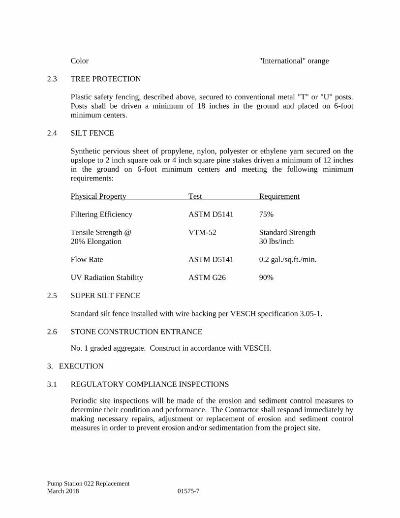
2.4 SILT FENCE
Synthetic pervious sheet of propylene, nylon, polyester or ethylene yarn secured on the
upslope to 2 inch square oak or 4 inch square pine stakes driven a minimum of 12 inches
in the ground on 6-foot minimum centers and meeting the following minimum
requirements:
Physical Property Test Requirement
Filtering Efficiency ASTM D5141 75%
Tensile Strength @ VTM-52 Standard Strength
20% Elongation 30 lbs/inch
Flow Rate ASTM D5141 0.2 gal./sq.ft./min.
UV Radiation Stability ASTM G26 90%
2.5 SUPER SILT FENCE
Standard silt fence installed with wire backing per VESCH specification 3.05-1.
2.6 STONE CONSTRUCTION ENTRANCE
No. 1 graded aggregate. Construct in accordance with VESCH.
3. EXECUTION
3.1 REGULATORY COMPLIANCE INSPECTIONS
Periodic site inspections will be made of the erosion and sediment control measures to
determine their condition and performance. The Contractor shall respond immediately by
making necessary repairs, adjustment or replacement of erosion and sediment control
measures in order to prevent erosion and/or sedimentation from the project site.
Pump Station 022 Replacement
March 2018 01575-8
3.1.1 Pre-Installation Meeting
The Contractor shall contact the local authority’s environmental compliance office prior
to performing any work on the project site to allow them to determine if a meeting to
review Sediment and Control measures is necessary or required.
3.2 PROTECTION OF NATURAL RESOURCES
Preserve the natural resources within the project boundaries and outside the limits of
permanent work. Restore to an equivalent or improved condition upon completion of
work. Confine construction activities to within the limits of the work indicated or
specified.
3.2.1 Land Resources
Except in areas to be cleared, do not remove, cut, deface, injure, or destroy trees or
shrubs without the Owner's permission. Do not fasten or attach ropes, cables, or guys to
existing nearby trees for anchorages unless authorized by the Owner. Where such use of
attached ropes, cables, or guys is authorized, the Contractor shall be responsible for any
resultant damage.
3.2.1.1 Protection of Trees
Protect existing trees which are to remain and which may be injured, bruised, defaced, or
otherwise damaged by construction operations. Remove displaced rocks from uncleared
areas. By approved excavation, remove trees with 30 percent or more of their root
systems destroyed. Delineate protected trees with safety fencing where noted on the
Drawings. Safety orange colored silt fence may be used in lieu of safety fencing where
approved by the environmental inspector.
3.2.1.2 Replacement
Remove trees and other landscape features scarred or damaged by equipment operations,
and replace with equivalent, undamaged trees and landscape features. Obtain Engineer's
approval before replacement.
3.2.2 Water Resources
3.2.2.1 Oily and Hazardous Substances
Prevent oily or other hazardous substances from entering the ground, drainage areas, or
local bodies of water. For oil, fuel oil, or other hazardous substance spills, verbally
notify the Engineer immediately. Surround all temporary fuel oil or petroleum storage
tanks with a temporary earth berm of sufficient size and strength to contain the contents
of the tanks in the event of leakage or spillage.
Pump Station 022 Replacement
March 2018 01575-9
3.2.2.2 Wetland Buffers
Disturbance within wetlands buffers is prohibited. Do not allow silt to enter wetlands
buffers. The limits of the wetland buffers are denoted on the drawings. Discharges from
dewatering operations must pass through an approved dewatering structure or sediment
trap prior to entering wetlands buffers. Delineate wetlands buffers with safety fencing
within 50 feet of disturbed areas. Safety orange colored silt fence may be used in lieu of
safety fencing.
3.2.3 Fish and Wildlife Resources
Do not disturb fish and wildlife. Do not alter water flows or otherwise significantly
disturb the native habitat adjacent to the project and critical to the survival of fish and
wildlife, except as indicated or specified.
3.3 HISTORICAL AND ARCHAEOLOGICAL RESOURCES
Carefully protect in-place and report immediately to the Engineer and Owner historical
and archaeological items or human skeletal remains discovered in the course of work.
Stop work in the immediate area of the discovery until directed by the Owner to resume
work. The Owner retains ownership and control over all historical and archaeological
resources.
3.4 EROSION AND SEDIMENT CONTROL MEASURES
All temporary or permanent erosion and sediment control practices necessary for
retaining sediments on the construction site shall be installed and tree protection fencing
shall be erected at the locations as specified on the site plan prior to any land clearing,
grubbing, grading or earth moving activities. Maintenance of all erosion and sediment
control practices shall be scheduled on a weekly basis and after each rainfall producing
runoff. Necessary repair, adjustment or replacement shall be performed immediately.
3.4.1 Burnoff
Burnoff of the ground cover is not permitted.
3.4.2 Protection of Erodible Soils
Immediately finish the earthwork brought to a final grade, as indicated or specified.
Where finished grades are not indicated, restore to original grade. Immediately protect
the side slopes and back slopes upon completion of rough grading. Plan and conduct
earthwork to minimize the duration of exposure of unprotected soils.
Pump Station 022 Replacement
March 2018 01575-10
3.4.2.1 Construction entrance (CE)
Stone pad(s) shall be installed concurrently with the initiation of clearing and grubbing
operations. Where construction vehicle access routes intersect paved roads, provisions
shall be made to minimize the transport of sediment by vehicular tracking onto the paved
surface. Where sediment is transported onto a public road surface, the road shall be
cleaned thoroughly at the end of each day. Sediment shall be removed from the roads by
shoveling or sweeping and transported to a sediment control disposal area. Street
washing shall be allowed only after sediment is removed as prescribed above.
3.4.3 Temporary Protection of Erodible Soils
Use the following methods to prevent erosion and control sedimentation:
3.4.3.1 Mechanical Retardation and Control of Runoff
Mechanically retard and control the rate of runoff from the construction site. This
includes construction of diversion ditches, benches, berms, and use of silt fences and
straw bales to retard and divert runoff to protected drainage courses and sediment
trapping devices.
3.4.3.1.1 Site Drainage
The installation of storm drainage facilities shall take precedence over all other
construction activities. Site drainage facilities shall be completed within 60 days
following completion of the rough grading operations at any point on the project.
3.4.3.1.2 Inlet Protection (IP)
Inlet protection practices shall be installed around the perimeter of all inlets to prevent
sediments from entering the structure prior to any clearing, grubbing, grading or earth
moving activities.
3.4.3.1.3 Sediment Basins (SB) / Sediment Traps (ST)
All effluent from excavations (including building) shall be filtered through a properly
sized sediment trap before discharging into the project storm drain system. The discharge
shall be filtered adequately so it does not adversely affect downstream wetlands.
Sediment basins and traps, perimeter dikes, sediment barriers and other measures
intended to trap sediment shall be constructed at the initiation of land disturbing
activities, and shall be made functional before upslope land disturbance takes place. The
basin(s) are to be kept clear of debris. Sediment accumulations shall be cleaned out
periodically during and after construction activities. All other storm water management
facilities shall be installed and made operational within 30 days following the start of
land disturbance.
Pump Station 022 Replacement
March 2018 01575-11
3.4.3.1.4 Diversions (DV), Diversion Dikes (DD), Outlet Protection (OP)
All temporary or permanent earthen structures such as dams, dikes and diversion shall be
stabilized (seeded) immediately after their construction. Stone outlet(s) shall be provided
as required.
3.4.3.1.5 Trenches and Dewatering Structures (DS)
All areas designated for underground utilities shall be stabilized as soon as practical but
not exceeding 15 days following their installation and backfilling. No more than 300 feet
of sanitary sewer, storm drain, water main, or any other line trench shall be opened at any
one time. Excavated material shall be placed on the uphill side of trenches. Effluent
from dewatering operations shall be filtered or passed through an approved sediment
trapping device, or both, and discharged in a manner that does not adversely affect
flowing streams or property beyond the contract limits.
3.4.3.2 Vegetation and Mulch
Provide temporary protection on sides and back slopes as soon as rough grading is
completed or sufficient soil is exposed to require erosion protection. Permanent or
temporary stabilization (PS & TS) shall be applied to denuded areas within seven days
after final grade is reached on any portion of the site. Temporary soil stabilization shall
be applied within seven days to denuded areas that may not be a final grade but will
remain dormant (undisturbed) for longer than 30 days. Permanent stabilization shall be
applied to areas that are to be left dormant for more than one year. Temporary vegetative
cover shall consist of seeding as scheduled on the drawings. Temporary vegetative cover
may be eliminated in favor of the permanent vegetative cover if site conditions permit
and the Architect/Engineer so directs. Protect slopes by accelerated growth of permanent
vegetation, temporary vegetation, mulching (MU), or netting. Stabilize slopes by
hydroseeding, anchoring mulch in place, covering with anchored netting, sodding, or
such combination of these and other methods necessary for effective erosion control.
Provide new seeding where ground is disturbed. Include topsoil (TO) or nutriment
during the seeding operation necessary to establish a suitable stand of grass. The seeding
operation shall be as specified on the Drawings.
3.4.3.2.1 Stockpile Treatment
Material such as topsoil, waste, spoils, sand and other erodible materials which are to be
stockpiled for use or later disposal shall be located away from streams, drainage ditches
and other waterways. Such stockpiles shall have slopes no steeper than a 2:1 ratio and
shall be protected against erosion with temporary vegetation, covers, and silt fencing
around the stockpile. Removal of material from such stockpile shall be done from the
side(s) away from the down grade slope. After each removal or stockpile operation,
disturbed area must be restabilized. Storage areas on the project site must be approved by
the Owner prior to installation.
Pump Station 022 Replacement
March 2018 01575-12
3.5 CONTROL AND DISPOSAL OF SOLID WASTES
Pick up solid wastes, and place in covered containers that are regularly emptied. Do not
prepare or cook food on the project site. Prevent contamination of the site or other areas
when handling and disposing of wastes. At project completion, leave the areas clean.
Remove all solid waste (including non-hazardous debris) from the property and dispose
off-site at an approved landfill. Solid waste disposal off-site must comply with most
stringent local, State, and Federal requirements including 40 CFR 241, 40 CFR 243, and
40 CFR 258.
3.6 CONTROL AND DISPOSAL OF HAZARDOUS WASTES
3.6.1 Hazardous Waste/Debris Management
The Contractor shall identify all construction activities which will generate hazardous
waste/debris. The Contractor must provide a documented waste determination for all
resultant waste streams. Hazardous waste/debris shall be identified, labeled, handled,
stored, and disposed of in accordance with all Federal, State, and local regulations
including 40 CFR 261, 40 CFR 262, 40 CFR 263, 40 CFR 264, 40 CFR 265, 40 CFR
266, and 40 CFR 268. Hazardous waste shall also be managed in accordance with the
approved Hazardous Waste Management Section of the Environmental Protection Plan.
Store hazardous wastes in approved containers in accordance with 49 CFR 173. No
hazardous waste shall be brought onto Owner property. For hazardous wastes spills,
verbally notify the Owner immediately. Spill response shall be in accordance with 40
CFR 300 and applicable State regulations.
3.7 DUST CONTROL
Keep dust down at all times, including during non-working periods. Sprinkle or treat,
with dust suppressants, the soil at the site, haul roads, and other areas disturbed by
operations. Dry power brooming will not be permitted. Instead, use vacuuming, wet
mopping, wet sweeping, or wet power brooming. Air blowing will be permitted only for
cleaning nonparticulate debris such as steel reinforcing bars. Only wet cutting will be
permitted for cutting concrete blocks, concrete, and bituminous concrete. Do not
unnecessarily shake bags of cement, concrete mortar, or plaster.
3.8 NOISE
Make the maximum use of low-noise emission products, as certified by the EPA.
Blasting or use of explosives will not be permitted.
END OF SECTION

Pump Station 022 Replacement
March 2018 01781-1
SECTION 01781 - OPERATION AND MAINTENANCE DATA
1. GENERAL
1.1 SUBMISSION OF OPERATION AND MAINTENANCE DATA
Submit operation and maintenance (O&M) data which is specifically applicable to this
contract and a complete and concise depiction of the provided equipment or product.
Data containing extraneous information to be sorted through to find applicable
instructions will not be accepted. Present information in sufficient detail to clearly
explain user O&M requirements at the system, equipment, component, and subassembly
level. Include an index preceding each submittal. Submit in accordance with Section
01330, "Submittal Procedures."
1.1.1 Quantity
Submit copies of the manufacturers' information specified herein for the components,
assemblies, subassemblies, attachments, and accessories. The items for which O&M data
is required are listed in the technical sections which specify that particular item. Where
not specifically called for in the technical sections, supply Data Package 2S.
1.1.2 Package Content
For each product, system, or piece of equipment requiring submission of O&M data,
submit the package required in the individual technical section. At a minimum, package
content shall be as required in the paragraph entitled "Schedule of Operations and
Maintenance Data Packages." The operation and maintenance manuals are to be put in a
format and with content acceptable to the locality and the Engineer.
1.1.3 Delivery
Four copies of Operations and Maintenance Manuals must be submitted to the Engineer
for review and approval prior to acceptance by the locality to operate the pump station.
Submit Operations and Maintenance data to the Engineer for review and approval to use
in the manual; submit data specified for a given item within 30 calendar days after the
item is delivered to the contract site. The locality will not accept the station without
submission of the Operation and Maintenance Manuals.
1.1.4 Changes to Submittals
Manufacturer-originated changes or revisions to submitted data shall be furnished by the
Contractor if a component of an item is so affected subsequent to acceptance of the O&M
data. Changes, additions, or revisions required by the Owner for final acceptance of
submitted data, shall be submitted by the Contractor within 30 calendar days of the
notification of this change requirement.
Pump Station 022 Replacement
March 2018 01781-2
1.2 TYPES OF INFORMATION REQUIRED IN O&M DATA PACKAGES
1.2.1 Safety Precautions
List personnel hazards and equipment or product safety precautions for all operating
conditions.
1.2.2 Startup, Shutdown, and Post-shutdown Procedures
Include a control sequence for each of these operations.
1.2.3 Environmental Conditions
Include a list of environmental conditions (temperature, humidity, and other relevant
data) which are best suited for each product or piece of equipment and describe
conditions under which equipment should not be allowed to run.
1.2.4 Lubrication Data
Include lubrication data, other than instructions for lubrication in accordance with
paragraph entitled "Operator Service Requirements":
A. A table showing recommended lubricants for specific temperature ranges and
applications;
B. Charts with a schematic diagram of the equipment showing lubrication points,
recommended types and grades of lubricants, and capacities; and
C. A lubrication schedule showing service interval frequency.
1.2.5 Troubleshooting Guides and Diagnostic Techniques
Include step-by-step procedures to promptly isolate the cause of typical malfunctions.
Describe clearly why the checkout is performed and what conditions are to be sought.
Identify tests or inspections and test equipment required to determine whether parts and
equipment may be reused or require replacement.
1.2.6 Wiring Diagrams and Control Diagrams
Wiring diagrams and control diagrams shall be point-to-point drawings of wiring and
control circuits including factory-field interfaces. Provide a complete and accurate
depiction of the actual job specific wiring and control work. On diagrams, number
electrical and electronic wiring and pneumatic control tubing and the terminals for each
type, identically to actual installation numbering.
Pump Station 022 Replacement
March 2018 01781-3
1.2.7 Maintenance and Repair Procedures
Include instructions and list tools required to restore product or equipment to proper
condition or operating standards.
1.3 SCHEDULE OF OPERATION AND MAINTENANCE DATA PACKAGES
Furnish the O&M data packages specified in individual technical sections. The required
information for each O&M data package is as follows:
1.3.1 Data Package 1S
A. Safety precautions
B. Environmental conditions
C. Wiring and control diagrams
D. Maintenance procedures
1.3.2 Data Package 2S
A. Safety precautions
B. Environmental conditions
C. Lubrication data
D. Wiring and control diagrams
E. Maintenance and repair procedures
F. Startup, shutdown, and post-shutdown procedures
G. Troubleshooting guides and diagnostic techniques
2. PRODUCTS
Not used.
3. EXECUTION
Not used.
END OF SECTION

Pump Station 022 Replacement
March 2018 01781-4
This Page Intentionally Left Blank
Pump Station 022 Replacement
March 2018 02060-1
SECTION 02060 — BUILDING AND STRUCTURE DEMOLITION
1. GENERAL
1.1 Summary
A. This section addresses the work related to furnishing all supervision, labor,
materials and equipment in the work for demolition of existing buildings and structures.
1.2 Section Includes
A. Demolition of designated structures and appurtenances, backfilling, and
removal of materials from site.
B. Demolition and removal of foundations and slabs-on-grade.
C. Disconnecting and abandonment or removal of identified utilities.
D. Filling of underground structures and abandonment of piping.
E. Demolition and removal of fences.
1.3 Record Drawings
A. Submit in accordance with supplemental specification for water and sanitary
sewer record drawings.
B. Accurately record actual locations of abandoned utilities or subsurface
obstructions remaining on site.
1.4 Regulatory Requirements
A. Comply with Laws and Regulations for demolition of structures, protection of
adjacent structures, dust control, runoff control, and disposal.
B. Obtain required permits from authorities.
C. Notify affected utility companies and CITY before starting work and comply
with their requirements.
D. Do not close or obstruct roadways or sidewalks without permits.
E. Conform to procedures applicable when hazardous or contaminated materials
are encountered.

Pump Station 022 Replacement
March 2018 02060-2
2. PRODUCTS
A. Lime shall be in accordance with the Erosion & Sediment Control Notes
within the Construction Documents.
B. Topsoil shall be in accordance with Erosion & Sediment Control Notes within
the Construction Documents.
C. Sand shall be defined as material complying with ASTM D2487 Unified Soil
Classification System groups SW and SP.
D. Fill shall be in accordance with Section 02315.
E. Flowable fill shall be in accordance with the Hampton Roads Planning
District Commission Regional Construction Standards, latest edition.
3. EXECUTION
3.1 Preparation
A. Provide, erect, and maintain temporary barriers and security devices.
B. Protect existing landscaping materials, appurtenances, and structures, which
are not to be demolished.
C. Prevent movement or settlement of adjacent structures. Provide bracing and
shoring.
D. Mark location of existing utilities.
E. Dewater all tanks and structures designated to be demolished; remove and
legally dispose of all liquid, sludge, and scum.
F. Remove all designated equipment, piping, electrical components, and
appurtenances.
3.2 Demolition Requirements
A. Conduct demolition to minimize interference with adjacent structures.
B. Cease operations immediately if adjacent structures appear to be in danger.
Notify CITY. Do not resume operations until so directed by CITY.
C. Conduct operations with minimum interference to public or private accesses.
Maintain and protect egress and access at all times.
D. Obtain written permission from adjacent property owners when
demolition equipment or activity will affect their property.
Pump Station 022 Replacement
March 2018 02060-3
E. Sprinkle Work with water to minimize dust. Provide hoses, water connections,
and water for this purpose.
F. Repair or replace structures, equipment, piping, etc. that is to remain in
service if they are damaged by demolition operations. CITY shall have sole
authority to determine whether repair or replacement is appropriate.
3.3 Demolition
A. Disconnect and cap all utilities designated for removal within demolition
areas, as required. Provide appropriate blind flanges, plugs, and caps for
remaining piping. When piping is removed in an area to be abandoned by
filling, remaining wall castings and pipes shall be plugged by filling with
flowable fill.
B. Remove foundation walls and footings to a minimum of 3 feet below finished
grade or as designated on the drawings. Structures less than 4 feet in depth
shall be removed entirely.
C. Remove concrete slabs on grade.
D. Add 200 pounds of agricultural grade lime in four (4) equally spaced (50 lb)
layers throughout fill as the structure is being filled with sand. Top-most lime
layer shall be 3-feet below finished grade.
E. Fill structures with sand and cover with 6-inch topsoil layer.
F. Remove demolished materials from site.
G. Do not burn materials on site. Leave site in clean condition.
H. Remove temporary work.
I. Fill and grade site; follow Section 02315.
J. Seed all areas of fill and other earth areas disturbed by operations; follow the
Erosion and Sediment Control Notes within the Construction Documents.
3.4 Schedules
A. The City shall be given the opportunity to salvage equipment from the existing
station prior to demolition. Removal and disposal of all remaining equipment
shall be the responsibility of the Contractor.
END OF SECTION

Pump Station 022 Replacement
March 2018 02060-4
This Page Intentionally Left Blank
Pump Station 022 Replacement
March 2018 02100-1
SECTION 02100 - CLEARING AND GRUBBING
1. GENERAL
1.1 DEFINITIONS
1.1.1 Clearing
Clearing is defined as the removal of trees, brush, down timber, rotten wood, rubbish, any
other vegetation, and objectionable material at or above original ground elevation not
designated to be saved; clearing also includes removal of fences, walls, guard posts, guard
rail, signs, and other obstructions interfering with the proposed work.
1.1.2 Grubbing
Grubbing is defined as the removal from below the surface of the natural ground of stumps,
roots and stubs, brush, organic materials, and debris.
1.2 JOB CONDITIONS
The Contractor may clear and grub all obstructions within the limits indicated. The
Contractor shall endeavor to minimize the clearing required and make every effort to save
trees and shrubbery. All areas disturbed during the course of construction shall be returned to
a condition equal to or better than those existing prior to the commencement of construction
and in accordance with the plans and specifications.
1.3 SUBMITTALS
Submit the following in accordance with Section 01330, "Submittal Procedures."
SD-02 Shop Drawings
VDOT Tree Trimming Permit
The Contractor will obtain the necessary permit, if required, and supply one copy to the
Owner.
Burning Permits
If permitted by local and state jurisdiction, provide one copy to the Engineer and post
and maintain one copy on-site with other permits.
Debris Disposal
If debris is to be disposed of on private lands, obtain a letter from the owner of the land
granting permission. Provide one copy to the Engineer.
Pump Station 022 Replacement
March 2018 02100-2
Erosion and Sediment Control Permit (aka Land Disturbing)
Will be acquired by the Contractor.
Certificate to Construct
Will be acquired by the Owner.
Post all permits in a weatherproofed enclosure visible from the entrance to the site. The
sign shall be a minimum of four feet off the ground.
2. PRODUCTS
2.1 TEMPORARY FENCING
Safety fencing specified in Section 01575, "Temporary Environmental Controls."
2.2 WOOD TREE GUARDS
2.2.1 Wood posts
2"x4" Southern Pine Lumber
2.2.2 Wood stringers
2"x2" Southern Pine Lumber
2.3 WRAPPING MATERIALS
2.3.1 Burlap
AASHTO M182, Class 1
2.3.2 Krinkle-kraft waterproof paper
4" width
2.4 TREE WOUND DRESSING
Antiseptic and waterproof, asphalt base.
2.5 STRAW BALES
Wheat or oat straw, reasonably free of viable seed, well cured.
Pump Station 022 Replacement
March 2018 02100-3
2.6 FILTER BARRIER:
Geotextile fabric conforming to Section 245.02 of the VDOT Road and Bridge
Specifications.
2.7 SILT FENCE
Conform to Section 01575, "Temporary Environmental Controls."
2.8 ROCK CHECK DAMS
Conform to Section 01575, "Temporary Environmental Controls."
2.9 CONSTRUCTION ENTRANCE:
Conform to Section 01575, "Temporary Environmental Controls."
3. EXECUTION
3.1 PREPARATION
1. Mark areas to be cleared, the areas to be grubbed, and items to be saved with stakes,
flags, paint or plastic colored ribbon for the approval of the Engineer.
2. Protect benchmarks, utilities, existing trees, shrubs and other landscape features
designated for preservation with temporary barricades satisfactory to the Engineer.
3. No material shall be stored or construction operation carried on within 5 feet of any
tree to be saved or within the tree protection fencing.
4. When a private enclosure fence encroaches on the work area, notify the property
owner at least 5 days in advance of the clearing/grubbing operations to permit the
owner to remove it, construct a supplemental fence, or make such other arrangements
as may be necessary for security purposes; in failure of the property owner to
reasonably proceed with the work required to secure his property, carefully remove
the fence, in whole or in part, and neatly pile the materials onto the owner's property.
3.2 CLEARING
Confine clearing to within the permanent and construction rights-of-way or property. Fell
trees in a manner that will avoid damage to trees, shrubs, and other installations which are to
be retained. Where stumps are not required to be grubbed, flush-cut with ground elevation.
Pump Station 022 Replacement
March 2018 02100-4
3.3 GRUBBING
Grub areas within the construction limits to remove roots and other objectionable material to
a minimum depth of 8". Remove all stumps within the cleared areas except those designated
to be saved as indicated on the plans.
3.4 STRIPPING AND STOCKPILING TOPSOIL
Strip topsoil to whatever depth it may occur from areas to be excavated, filled, or graded and
stockpile at a location approved by the Engineer for use in finish grading. The topsoil is the
property of the Owner and shall not be used as backfill. Topsoil shall not be removed from
the site unless otherwise authorized by Engineer. Provide silt fence around toe of stockpile.
3.5 DEBRIS DISPOSAL
Trees, logs, branches, brush, stumps, and other debris resulting from clearing and grubbing
operations shall become the property of the Contractor and shall be legally disposed of. Do
not deposit or bury on the site debris resulting from the clearing and grubbing work. Debris
may be burned on-site if local ordinances allow open-air burning, if required permits are
obtained, and if burning operations are conducted in compliance with local ordinances and
regulations. Burning contract and permits shall be acquired by Contractor.
3.6 RESTORATION
Repair all injuries to bark, trunk, limbs, and roots of remaining plants by properly dressing,
cutting, tracing and painting, using approved arboricultural practices and materials. Replace
trees, shrubs and plants designated to be saved which are permanently injured or die during
the period of the warranty as a result of construction operations with like species acceptable
to the Owner. Remove protective fences, enclosures and guards upon the completion of the
project. Restore guard posts, guard rail, signs and other interferences to the condition equal
to that existing before construction operations.
3.7 ENVIRONMENTAL CONTROLS
Install in accordance with details shown on drawings, in accordance with Section 01575,
"Temporary Environmental Controls," and in compliance with all applicable sections of the
Virginia Erosion and Sediment Control Handbook, latest edition.
END OF SECTION
Pump Station 022 Replacement
March 2018 02315-1
SECTION 02315 - EXCAVATION AND FILL
1. GENERAL
1.1 REFERENCES
The publications listed below form a part of this specification to the extent referenced.
The publications are referred to within the text by the basic designation only. The
referenced publications shall be the current effective edition.
AMERICAN SOCIETY FOR TESTING AND MATERIALS (ASTM)
ASTM C 33 Concrete Aggregates
ASTM C 136 Sieve Analysis of Fine and Coarse Aggregates
ASTM D 698 Laboratory Compaction Characteristics of Soil Using
Standard Effort (12,400 ft-lbf/ft (600 kN-m/m))
ASTM D 1140 Amount of Material in Soils Finer Than the No. 200
(75-Micrometer) Sieve
ASTM D 1556 Density and Unit Weight of Soil in Place by the Sand-
Cone Method
ASTM D 1557 Laboratory Compaction Characteristics of Soil Using
Modified Effort (56,000 ft-lbf/ft (2,700 kN-m/m))
ASTM D 1883 Standard Test Method for California Bearing Ratio
(CBR) of Laboratory-Compacted Soils
ASTM D 2487 Classification of Soils for Engineering Purposes
(Unified Soil Classification System)
ASTM D 4318 Liquid Limit, Plastic Limit, and Plasticity Index of Soils
AMERICAN WATER WORKS ASSOCIATION (AWWA)
AWWA C600 Installation of Ductile-Iron Water Mains and Their
Appurtenances
CORPS OF ENGINEERS (COE)
COE EM-385-1-1 Safety and Health Requirements Manual
Pump Station 022 Replacement
March 2018 02315-2
1.2 SUBMITTALS
Submit the following in accordance with Section 01330 "Submittal Procedures."
SD-06 Test Reports
Fill, common fill and backfill test
Select material test
Capillary Water Barrier
Density tests
1.3 DELIVERY, STORAGE, AND HANDLING
Perform in a manner to prevent contamination or segregation of materials.
1.4 CRITERIA FOR BIDDING
Base bids on the following criteria:
A. Surface elevations are as indicated.
B. Pipes or other artificial obstructions, except those indicated, will not be encountered.
C. Groundwater elevations indicated by the boring log were those existing at the time
subsurface investigations were made and do not necessarily represent groundwater
elevation at the time of construction.
D. Character of soil material to be encountered is as indicated in the geotechnical
evaluation report.
E. Hard materials will not be encountered.
F. Blasting will not be permitted. Remove material in a manner approved by the
Owner.
2. PRODUCTS
2.1 SOIL MATERIALS
Free of debris, roots, wood, scrap material, vegetation, refuse, soft unsound particles, and
frozen, deleterious, unsuitable or objectionable materials. Unless specified otherwise, the
maximum particle diameter shall not exceed one-half the lift thickness at the intended
location.
Pump Station 022 Replacement
March 2018 02315-3
2.1.1 Common Fill
Unclassified soil material that can be compacted to form a dense stable soil mass to the
density specified for the intended location.
2.1.2 Backfill and Fill Material (Not at Building or Vaults Foundations)
ASTM D 2487, classification GW, GP, GM, GC, SW, SP, SM, SC with a maximum
ASTM D 4318 liquid limit of 35, maximum ASTM D 4318 plasticity index of 12, and a
maximum of 25 percent by weight passing ASTM D 1140, No. 200 sieve.
Contractor shall re-utilize suitable excavated material as fill. Contractor shall coordinate
with the City for excavated material suitability. Excavated material deemed suitable for
use shall be stored onsite if not needed when first excavated. (May not leave then come
back).
2.1.3 Backfill and Fill Material (At Building and Vault Foundations)
ASTM D 2487, classification GW, GP, SW, SP, SM, with a maximum ASTM D 4318
liquid limit of 20, maximum ASTM D 4318 plasticity index of 6, a maximum of 25
percent by weight passing ASTM D 1140, No. 200 sieve and should be free of rubble,
organics, clay, debris and other unsuitable material.
2.1.4 Topsoil
Natural, friable soil representative of productive, well-drained soils in the area, free of
subsoil, stumps, rocks larger than one inch diameter, brush, weeds, toxic substances, and
other material detrimental to plant growth. Amend topsoil pH range to obtain a pH of 5.5
to 7.
2.1.5 Select Material
ASTM D 2487, classification GW, GP, SW, SP with not more than 5 percent by weight
passing ASTM D 1140, No. 200 sieve, and maximum particle size not exceeding 2
inches.
2.2 CAPILLARY WATER BARRIER
ASTM C 33, coarse aggregate Size 57, 67, or 7 with a maximum of 3 percent by weight
passing ASTM D 1140, No. 200 sieve, and conforming to the general soil material
requirements specified in paragraph entitled "Soil Materials."
Pump Station 022 Replacement
March 2018 02315-4
2.3 BORROW
Obtain borrow materials required in excess of those furnished from excavations from
sources off-site or identified by the Owner.
2.4 BURIED WARNING AND IDENTIFICATION TAPE
Metallic core or metallic-faced, acid- and alkali-resistant, polyethylene plastic warning
tape manufactured specifically for warning and identification of buried utility lines.
Provide tape on rolls, 6-inch minimum width, color coded as specified below for the
intended utility with warning and identification imprinted in bold black letters
continuously over the entire tape length. Warning and identification to read,
"CAUTION, BURIED (intended service) LINE BELOW" or similar wording. Color and
printing shall be permanent, unaffected by moisture or soil.
Warning Tape Color Codes
Red: Electric
Yellow: Gas, Oil, Dangerous Materials
Orange: Telephone and Other Communications
Blue: Water Systems
Green: Sewer Systems
2.5 PIPE BEDDING AND AGGREGATE BASES
ASTM C 33, coarse aggregate Size 57, 67, or 7 with a maximum of 3 percent by weight
passing ASTM D 1140, No. 200 sieve, and conforming to the general soil material
requirements specified in paragraph entitled "Soil Materials."
3. EXECUTION
3.1 PREPARATION
3.1.1 Protection
3.1.1.1 Protection Systems
Provide shoring, bracing, and sheeting in accordance with COE EM-385-1-1.
3.1.1.2 Site Drainage
Provide for the collection and disposal of surface and subsurface water and waterborne
sediment encountered during construction. Provide appropriate erosion and sediment
control measures as indicated and in accordance with Section 01575, “Temporary
Environmental Controls.”
Pump Station 022 Replacement
March 2018 02315-5
3.1.2 Surface Preparation
3.1.2.1 Clearing and Grubbing
Comply with Section 02100, “Clearing and Grubbing.”
3.1.2.2 Stripping
Strip existing topsoil to a depth of 4 inches without contamination by subgrade material.
Stockpile topsoil separately from other excavated material and locate convenient to finish
grading area.
3.1.2.3 Unsuitable Material
Remove vegetation, debris, decayed vegetable matter, sod, mulch, and rubbish
underneath paved areas, foundations or concrete slabs.
3.2 UNDERGROUND UTILITIES
Location of the existing utilities indicated is approximate. The Contractor shall
physically verify the location and elevation of the existing utilities indicated prior to
starting construction. Conform to Section 01014, "Protection of Underground Utilities."
3.3 EXCAVATION
Excavate to contours, elevation, and dimensions indicated. Reuse excavated materials
that meet the specified requirements for the material type required at the intended
location. Keep excavations free from water. Discharge from dewatering operations shall
be directed to appropriate sediment trapping devices. Excavate soil softened or made
unsuitable for subsequent construction due to exposure to weather or due to Contractor's
operations. Refill with backfill and fill material and compact to 95 percent of ASTM D
698 maximum density. Unless specified otherwise, refill excavations cut below indicated
depth with backfill and fill material and compact to 95 percent of ASTM D 698,
maximum density at no additional cost or time.
3.3.1 Pipe, Conduit and Utility Trenches
Excavate to the dimension indicated. Grade bottom of trenches to provide uniform
support for each section of pipe after pipe bedding placement.
3.4 FILLING AND BACKFILLING
3.4.1 Common Fill Placement
Provide for general site. Place in 6 inch lifts. Compact areas not accessible to rollers or
compactors with mechanical hand tampers. Aerate material excessively moistened by
Pump Station 022 Replacement
March 2018 02315-6
rain to satisfactory moisture content. Finish to a smooth surface by blading, rolling with
a smooth roller, or both.
3.4.2 Backfill and Fill Material Placement
Provide for paved areas and under concrete slabs, except where select material is
provided. Place in 6 inch lifts. Place backfill material adjacent to structures as the
structural elements are completed and accepted. Backfill against concrete only when
approved. Place and compact material to avoid loading upon or against the structure.
3.4.3 Select Material Placement
Provide under capillary water barrier for structures not pile supported. Place in 6-inch
lifts. Placement adjacent to structures shall be as structural elements are complete and
accepted. Place against concrete only when approved. Place and compact material to
avoid loading upon or against structure.
3.4.4 Capillary Water Barrier
Provide under floor slab on a compacted subgrade. Place in 4-inch lifts.
3.4.5 Trench Backfilling
Backfill as rapidly as construction, testing, and acceptance of work permits. Place and
compact backfill under structures and paved areas in 6-inch lifts to top of trench and in 6
inch lifts to one foot over pipe outside structures and paved areas.
3.4.5.1 Buried Warning and Identification Tape
Provide buried utility lines with utility identification tape. Bury tape 12-inches below
finished grade; under pavements and slabs, bury tape 6-inches below top of subgrade.
3.4.5.2 Bedding Requirements
Except as specified otherwise in the individual piping section or where indicated, provide
bedding for buried piping in accordance with AWWA C600, Type 4, except as specified
herein. Backfill to top of pipe, to top of trench under structures and paved areas, shall be
compacted to 95 percent of ASTM D 698 maximum density.
3.5 COMPACTION
Expressed as a percentage of maximum density at optimal moisture content. Determine
in-place density of existing subgrade; if required density exists, no compaction of
existing subgrade will be required.

Pump Station 022 Replacement
March 2018 02315-7
3.5.1 General Site
Compact underneath areas designated for vegetation and areas outside the 5-foot line
measured from the toe of the concrete foundation to 80 percent of ASTM D 698.
3.5.2 Structures and Concrete Slabs
Compact subgrades of structures, foundations and slabs to 95 percent of ASTM D 1557.
Compact select material beneath concrete slabs and drainage structures to 95 percent of
ASTM D 698.
3.5.3 Capillary Water Barrier
Compact with two passes of a hand-operated, plate type vibratory compactor.
3.5.4 Foundation Backfill
Compact areas within 5-feet of the toe of the foundation to 95 percent of ASTM D 1557.
3.5.5 Paved Areas
Compact top 12-inches of subgrades to 95 percent of ASTM D 1557. Compact fill and
backfill materials to 95 percent of ASTM D 698.
3.5.6 Sidewalks
Compact top 6-inches of subgrade to 95 percent of ASTM D 698. Compact aggregate
bedding materials to 95 percent of ASTM D 698.
3.5.7 Deep Fill Consolidation
Fills greater than 10 feet deep shall be allowed to consolidate after placement in
accordance with recommendations from the geotechnical engineer prior to construction
of pavements, building structures, or slabs on the fill. Maximum long term settlement
shall not exceed 1 inch for pavements and equipment slabs and ½ inch for building
structures.
3.6 GRADING
Finish grades as indicated within one-tenth of one-foot. Grade areas to drain water away
from structures. For existing grades that will remain but which were disturbed by
Contractor's operations, grade as directed.

Pump Station 022 Replacement
March 2018 02315-8
3.6.1 Topsoil
Scarify existing subgrade. Provide 4-inches of topsoil for newly graded finish earth
surfaces and areas disturbed by the Contractor. Additional topsoil will not be required if
work is performed in compliance with stripping and stockpiling requirements. If there is
insufficient on-site topsoil meeting specified requirements for topsoil, provide topsoil
required in excess of that available. Seed in accordance with Section 02900,
"Landscaping and Seeding."
3.7 DISPOSITION OF SURPLUS MATERIAL
Remove from the project site surplus or other soil material not required or suitable for
filling or backfilling, and brush, refuse, stumps, roots, and timber.
3.8 FIELD QUALITY CONTROL
3.8.1 Sampling
Take the number and size of samples required to perform the following tests.
3.8.2 Testing
Perform one of each of the following tests for each material used. Provide additional
tests for each source change.
3.8.2.1 Fill, Common Fill and Backfill Material Testing
Test fill, common fill, and backfill material in accordance with ASTM C 136 for
conformance to ASTM D 2487 gradation limits; ASTM D 1140 for material finer than
the No. 200 sieve; ASTM D 4318 for liquid limit and for plastic limit; ASTM D 698 or
ASTM D 1557 for moisture density relations, as applicable.
3.8.2.2 Select Material Testing
Test select material in accordance with ASTM C 136 for conformance to ASTM D 2487
gradation limits; ASTM D 1140 for material finer than the No. 200 sieve; ASTM D 698
or ASTM D 1557 for moisture density relations, as applicable.
3.8.2.3 Capillary Water Barrier Material Testing
Test porous fill in accordance with ASTM C 136 for conformance to gradation specified
in ASTM C 33.
Pump Station 022 Replacement
March 2018 02315-9
3.8.2.4 Density Tests
Test density in accordance with ASTM D 1556. Perform an ASTM D 1556 density test
at the start of the job. Test each lift at randomly selected locations every 500 square feet
of subgrade in fills for structures and concrete slabs, and every 625 square feet for other
fill areas and every 500 square feet of subgrade in cut.
END OF SECTION

Pump Station 022 Replacement
March 2018 02315-10
This Page Intentionally Left Blank
Pump Station 022 Replacement
March 2018 02610-1
SECTION 02610 – UNDERGROUND UTILITY PIPE
1. GENERAL
This section refers to gravity sanitary sewer pipe, force main pipe, fittings, and
accessories required for buried service outside the building perimeter. Interior process
pipe and fittings shall comply with Section 15060, “Interior Process Pipe, Fittings And
Valves.” Domestic water supply piping shall comply with Section 15210, “Domestic
Water and Waste Piping.” Underground utilities shall comply with the Hampton Roads
Planning District Commission Regional Construction Standards, latest edition.
1.1 REFERENCES
The publications listed below form a part of this specification to the extent referenced.
The publications are referred to in the text by the basic designation only. The referenced
publications shall be the current effective edition.
AMERICAN SOCIETY FOR TESTING AND MATERIALS (ASTM)
ASTM D3139 Joints for Plastic Pressure Pipes Using Flexible
Elastomeric Seals
AMERICAN WATER WORKS ASSOCIATION (AWWA)
AWWA/ANSI C104/A21.4 Cement-Mortar Lining for Ductile-Iron Pipe and Fittings
for Water
AWWA/ANSI C110/A21.10 Ductile-Iron and Gray-Iron Fittings, 3 in. Through 48 in.
(75 mm Through 1200 mm), for Water and Other
Liquids
AWWA/ANSI C111/A21.11 Rubber-Gasket Joints for Ductile-Iron Pressure Pipe and
Fittings
AWWA/ANSI C151/A21.51 Ductile-Iron Pipe, Centrifugally Cast, for Water or Other
Liquids
AWWA/ANSI C153/A21.53 Ductile-Iron Compact Fittings, 3 in. Through 24 in. (76
mm Through 610 mm) and 54 in. Through 64 in. (1,400
mm Through 1,600 mm), for Water Service
AWWA C509 Resilient-Seated Gate Valves for Water-Supply Service
AWWA C600 Installation of Ductile-Iron Water Mains and Their
Appurtenances
Pump Station 022 Replacement
March 2018 02610-2
AWWA C605 Underground Installation of Polyvinyl Chloride (PVC)
Pressure Pipe and Fittings for Water
AWWA C900 Polyvinyl Chloride (PVC) Pressure Pipe, and Fabricated
Fittings, 4 In.-12 In. (100 mm-300 mm), for Water
Distribution
AWWA C909 Molecularly Oriented Polyvinyl Chloride (PVCO)
Pressure Pipe, 4 In.-12 In. (100 mm-300 mm), for Water
Distribution
1.2 SUBMITTALS
Submit the following in accordance with Section 01330, "Submittal Procedures."
SD-03 Product Data
Submit manufacturer’s standard catalog data sheets for pipe, pipe fittings, joints, joint
gaskets, lubricants, valves, and appurtenances.
SD-07 Certificates
Submit each manufacturer's certification attesting that the pipe, pipe fittings, joints,
joint gaskets, lubricants, valves, and appurtenances meet or exceed specification
requirements.
1.3 PRODUCT DELIVERY, STORAGE AND HANDLING
1.3.1 Delivery and Handling
Do not place materials on private property without written permission of the property
owner. During loading, transporting and unloading, exercise care to prevent damage to
materials. Do not drop pipe or fittings. Avoid shock or damage at all times. Take
measures to prevent damage to the exterior surface or internal lining of the pipe.
1.3.2 Storage
Do not stack pipe higher than recommended by the pipe manufacturer. Store all PVC
products and gaskets in a cool, dry location out of direct sunlight, covering if necessary,
and not in contact with petroleum products.
Pump Station 022 Replacement
March 2018 02610-3
2. PRODUCTS
2.1 SANITARY SEWER SYSTEM
Sanitary force main and gravity systems shall comply with the HRPDC Regional
Construction Standards.
2.2 MARKING TAPE
All pipelines shall be marked with a continuous strip of identification tape as specified in
Section 02315, "Excavation and Fill."
3. EXECUTION
3.1 PREPARATION
Perform trench excavation to the line and grade indicated on the Contract Drawings and
in accordance with Section 02315, "Excavation and Fill." Unless otherwise indicated on
the Contract Drawings, provide for a minimum cover of 36-inches above the top of
piping laid in trenches. Provide pipe bedding as specified in Section 02315, “Excavation
and Fill” and as detailed in the HRPDC Regional Construction Standards. Place bedding
in a manner to avoid segregation, and compact to the maximum practical density so that
the pipe can be laid to the required tolerances.
3.2 SANITARY SEWER SYSTEM
Install sanitary gravity and force main sewer systems in accordance with Division 8 of the
HRPDC Regional Construction Standards.
3.3 LAYING PIPE IN TRENCHES
Lower pipe into trench using handling equipment designed for the purpose to assure
safety of personnel and to avoid damage to pipe. Do not drop pipe. Chains will not be
permitted. Lay pipe proceeding upgrade with the bell or groove pointing upstream. Lay
pipe to a true uniform line with the barrel of the pipe resting solidly in pipe bedding
material throughout its length. Excavate recesses in pipe bedding material to
accommodate joints, fittings and appurtenances. Do not subject pipe to a blow or shock to
achieve solid bearing or grade. Lay each section of pipe in such a manner as to form a
close concentric joint with the adjoining section and to avoid offsets in the flow line.
Clean and inspect each section of pipe before joining. Assemble to provide tight, flexible
joints that permit movement caused by expansion, contraction, and ground movement.
Use lubricant recommended by the pipe or fitting manufacturer for making joints. If
unusual joining resistance is encountered or if the pipe cannot be fully inserted into the
bell, disassemble joint, inspect for damage, re-clean joint components, and reassemble.
Pump Station 022 Replacement
March 2018 02610-4
3.4 PROGRESSION OF WORK
Disassemble and remake improperly assembled joints using a new gasket. Check each
pipe installed as to line and grade in place. Correct deviation from grade immediately. A
deviation from the designed grade as shown on the Contract Drawings, or deflection of
pipe joints, will be cause for rejection. Place sufficient backfill on each section of pipe,
as it is laid, to hold firmly in place. Clean interior of the pipe as work progresses. Where
cleaning after laying is difficult because of small pipe size, use a suitable swab or drag in
the pipe and pull forward past each joint immediately after the jointing has been
completed. Keep trenches and excavations free of water during construction. When the
work is not in progress, and at the end of each workday, securely plug open ends to
prevent trench water, earth, or other substances from entering the pipes or fittings.
3.5 DEFLECTION:
When it is necessary to deflect pressure mains from a straight alignment horizontally or
vertically, do not exceed 50% of manufacturer’s recommendations or per AWWA C600
or AWWA C605, as applicable, whichever is most stringent.
3.6 THRUST RESTRAINT
Provide thrust restraints for pressure pipeline at all bends, tees, valves and changes in
direction as indicated on the Drawings.
3.7 CAST-IN-PLACE CONCRETE CONSTRUCTION
Conform to the applicable requirements of Section 03300, “Cast-In-Place Concrete,” and
as detailed on the drawings.
3.8 BACKFILLING TRENCHES
Backfill trenches as specified in Section 02315, "Excavation and Fill."
3.9 TESTING
Provide testing in accordance with applicable provisions of Section 15190, "Hydrostatic
Testing of Piping Systems."
END OF SECTION
Pump Station 022 Replacement
March 2018 02741-1
SECTION 02741 - BITUMINOUS CONCRETE PAVEMENT
1. GENERAL
1.1 REFERENCES
The publications listed below form a part of this specification to the extent referenced.
The publications are referred to within the text by the basic designation only. The
referenced publications shall be the current effective edition.
AMERICAN SOCIETY FOR TESTING AND MATERIALS (ASTM)
ASTM D 1559 Resistance to Plastic Flow of Bituminous Mixtures
Using Marshall Apparatus
1.2 REGULATORY REQUIREMENTS
Work specified in this section shall be in accordance with the Virginia Department of
Transportation (VDOT), Road and Bridge Specifications, Latest Edition, except that
contractual and payment provisions do not apply, and are hereby made a part of these
specifications and as specified on the plans. The specification sections referred to herein are
VDOT specifications.
1.3 QUALITY ASSURANCE
1.3.1 Final Paving
The final layer of asphaltic concrete paving shall be placed no earlier than 30 days prior
to substantial completion of the project unless a written request is received and approved
by the Owner or his representative.
1.3.2 Warranty
Replace without additional cost to the Owner, all sections of paving which may become
defective within a year after date of Substantial Completion. Maintain paving free of
vegetation growing through from below for one year after date of Substantial
Completion. Any procedure required for eradication of such vegetation growth shall be
subject to approval of the Owner.
1.4 SUBMITTALS
Submit the following in accordance with Section 01330, "Submittal Procedures."
Pump Station 022 Replacement
March 2018 02741-2
SD-07 Certificates
Asphalt concrete: Submit certificates, signed by the producer, that paving
materials and incidental construction items conform to specification requirements.
2. PRODUCTS
2.1 ASPHALT CONCRETE
Provide asphalt concrete in accordance with applicable requirements of the VDOT Road
and Bridge Specifications, except where specified otherwise.
2.2 SUBGRADE MATERIALS
The subgrade shall be thoroughly compacted in accordance with Section 02315,
"Excavation and Fill," and as indicated on the drawings. If material unsuitable for subgrade
is encountered during compaction, the Contractor will be required to remove the unsuitable
material and backfill with suitable soil materials. If the backfill materials are overly wet or
dry, the Contractor shall manipulate until satisfactory or at his option remove and replace at
his own expense. The extent of undercutting and backfilling operations will be determined
by the Owner’s representative.
2.3 SUBBASE MATERIALS
Stone Base Course: #21-A or #21-B Graded Aggregate per Section 208 of the VDOT
Specifications, unless otherwise indicated.
2.4 PRIME COAT
The stone base course shall receive a prime coat of liquid asphalt (RC-250), prior to
subsequent course. Material and application shall conform to Sections 210 and 311 of the
VDOT Specifications. Application rates shall be .20-.25 gallon per square yard. Contractor
to immediately remove any materials, which during the application thereof, are accidentally
splattered onto curbs and gutters, etc. If bituminous pavement is 4 1/2 inches finished
thickness or more, prime coat may be omitted.
2.5 TACK COAT
The asphaltic concrete paving base course shall receive a tack coat of liquid asphalt (RC-
250), prior to subsequent course. Material and application shall conform to Sections 210
and 311 of the VDOT Specifications. Application rates shall be 0.05 - 0.10 gallons per
square yard for undiluted asphalt. Diluted asphalt shall be applied at a rate of 0.10 - 0.15
gallons per square yard. If pavement surface has not been contaminated or exposed for
more than 72 hours, tack coat may be omitted upon approval by the Engineer.
Pump Station 022 Replacement
March 2018 02741-3
2.6 BASE COURSE MATERIALS
The Contractor shall provide the asphalt course as indicated. Base Course shall conform to
Section 211 of the VDOT Specifications, Type BM-3 (Type BM-25.0 using "Superpave"
Mixtures). Irregularities, roller marks, etc. will not be accepted.
2.7 SURFACE COURSE MATERIALS
The Contractor shall provide the asphalt course as indicated. Wearing course shall conform
Section 211 of the VDOT Specifications, Type SM-2A (Type SM-9.5A using "Superpave"
Mixtures). Irregularities, roller marks, etc. will not be accepted.
2.8 EXCAVATION AND FILLING
Excavation and filling to establish elevation of subgrade is specified in Section 02315,
"Excavation and Fill."
3. EXECUTION
3.1 CONSTRUCTION
Provide construction in accordance with applicable requirements of the VDOT Road and
Bridge Specifications, except where indicated or specified otherwise.
3.1.1 Subgrade
Prepare subgrade in accordance with Section 02315, "Excavation and Fill."
3.1.2 Subbase
Construct subbase as specified on the plans and in accordance with Section 308 and 309 of
the VDOT Specifications. The stone subbase course shall be proof-rolled and soft spots
replaced by the Contractor at his expense.
3.1.3 Base Course
Construct base course in accordance with Section 315 of the VDOT Specifications.
Provide Prime Coat prior to placing base course as specified herein. Compact asphalt
mixture to 95 percent of that attained in a laboratory specimen of same mixture prepared
in accordance with ASTM D 1559.
Pump Station 022 Replacement
March 2018 02741-4
3.1.4 Surface Course
Construct wearing course in accordance with Section 315 of the VDOT Specifications.
Provide tack coat on base course as specified herein. Compact asphalt mixture to 95
percent of that attained in a laboratory specimen of same mixture prepared in accordance
with ASTM D 1559.
3.2 PROTECTION
Immediately after placement, protect pavement from mechanical injury until surface
temperature is less than 140 degrees F (60 degrees C). Vehicular traffic shall be prohibited
from newly paved areas for 12 hours.
3.3 TOLERANCES
Upon completion of grading operations, subgrade shall be firm, hard and unyielding with a
true, even and uniform surface at required grades; finished grades shall not show any
deviation in excess of 0.04' from intended grade when tested with a 10-foot straightedge.
Minor pavement surface projections, joints and minor honeycombed surfaces shall be ironed
smooth to grade as may be directed by the Owner’s representative.
3.4 FIELD QUALITY CONTROL
Testing shall be provided by the Contractor in the presence of the Owner’s representative.
Stone base and asphalt pavement compaction shall be tested every 6,000 square feet.
3.5 MAINTENANCE
Maintain subgrade in its final condition until surfacing is completed. Maintain ditches,
drains and flowlines along subgrade to drain effectively at all times.
3.6 CLEAN-UP
Operations include removal of oil splashes from adjacent construction and prompt removal
from site of excess excavated materials, debris and surplus materials.
END OF SECTION
Pump Station 022 Replacement
March 2018 02821-1
SECTION 02821- CHAIN LINK FENCES AND GATES
1 GENERAL
1.1 REFERENCES
The publications listed below form a part of this specification to the extent referenced.
The publications are referred to within the text by the basic designation only. The
referenced publications shall be the current effective edition.
AMERICAN SOCIETY FOR TESTING AND MATERIALS (ASTM)
ASTM B 117 Operating Salt Spray (Fog) Apparatus
ASTM C 94 Ready-Mixed Concrete
ASTM F 883 Padlocks
ASTM F 1043 Strength and Protective Coatings on Metal Industrial
Chain Link Fence Framework
FEDERAL SPECIFICATIONS (FS)
FS RR-F-191 Fencing, Wire and Post Metal (and Gates, Chain-Link
Fence Fabric, and Accessories) (General Specification)
FS RR-F-191/1 Fencing, Wire and Post, Metal (Chain-Link Fence
Fabric) (Detail Specification)
FS RR-F-191/2 Fencing, Wire and Post, Metal (Chain-Link Fence
Gates) (Detail Specification)
FS RR-F-191/3 Fencing, Wire and Post, Metal (Chain-Link Fence Posts,
Top Rails and Braces) (Detail Specification)
FS RR-F-191/4 Fencing, Wire and Post, Metal (Chain-Link Fence
Accessories) (Detail Specification)
Pump Station 022 Replacement
March 2018 02821-2
1.2 SUBMITTALS
Submit the following in accordance with Section 01330, "Submittal Procedures."
SD-02 Shop Drawings
Gates
Post spacing
Privacy Slats
SD-03 Product Data
Chain-link fencing components
Accessories
SD-08 Manufacturer's Instructions
Fence
Gates
1.3 DELIVERY, STORAGE, AND HANDLING
Deliver materials to site in an undamaged condition. Store materials off the ground to
provide protection against oxidation caused by ground contact.
2 PRODUCTS
2.1 CHAIN-LINK FENCING AND ACCESSORIES
FS RR-F-191 and detailed specifications as referenced and other requirements as
specified.
2.1.1 Fabric
FS RR-F-191/1; Type IV, polyvinyl chloride (PVC) coated over zinc- or aluminum-
coated steel, 9-gage core wire size. Mesh size, 2 inches. Provide selvage knuckled at
both selvages. Height of fabric, as indicated. Color shall be chosen by Architect upon
submittal of manufacturer’s standard color pallet.
Pump Station 022 Replacement
March 2018 02821-3
2.1.2 Gates
FS RR-F-191/2; Type I, single swing or Type II, double swing, as indicated. Shape and
size of gate opening, as indicated. Framing and bracing members, round steel alloy.
PVC-coated over zinc- or aluminum-coated steel. Gate frames and braces of minimum
sizes listed in FS RR-F-191/3 for each Class and Grade except that steel pipe frames shall
be 1.90 inches od, 0.120 inches minimum wall thickness. Gate fabric, as specified for
fencing fabric. Coating for steel latches, stops, hinges, keepers, and accessories, shall be
galvanized. Gate latches, fork type. Gate leaves more than 8 feet wide shall have
intermediate members as necessary to provide rigid construction, free from sag or twist.
Gate leaves less than 8 feet wide shall have truss rods or intermediate braces. Attach gate
fabric to gate frame in accordance with manufacturer's standards, except that welding will
not be permitted. Arrange padlocking latches to be accessible from both sides of gate,
regardless of latching arrangement.
2.1.3 Posts, Rails, and Braces
FS RR-F-191/3 line posts; Class 1, steel pipe, Grade A or B. End, corner, and pull posts;
Class 1, steel pipe, Grade A or B. Braces and rails; Class 1, steel pipe, Grade A or B., in
minimum sizes listed in FS RR-F-191/3 for each class and grade. Provide PVC color
coating, minimum thickness, 0.10 inch.
2.1.3.1 Composite Posts
Composite Posts shall not be permitted on this job site.
2.1.4 Fencing Accessories
FS RR-F-191/4. Provide wire ties constructed of the same material as the fencing fabric.
Provide accessories with polyvinyl (PVC) coatings similar to that specified for chain-link
fabric or framework.
2.1.5 Privacy Slats
Provide where indicated on Architectural Elevations. Opaque “M” shaped UV stabilized
plastic slat for use with chain link fencing. Lite Link Fence Slat or approved equivalent.
Color shall be chosen by Architect upon submittal of manufacturer’s standard color
pallet.
2.1.6 Concrete
Provide as specified in Section 03300, "Cast-In-Place Concrete."
2.1.7 Grout
Provide grout of proportions one part Portland Cement to three parts clean, well-graded
sand and a minimum amount of water to produce a workable mix.
Pump Station 022 Replacement
March 2018 02821-4
3 EXECUTION
3.1 SITE PREPARATION
3.1.1 Clearing and Grading
Clear fence line of trees, brush, and other obstacles to install fencing. Establish a graded,
compacted fence line prior to fencing installation. Compact fill used to establish fence
line.
3.1.2 Excavation
Excavate to dimensions indicated for concrete-embedded items, except in bedrock. If
bedrock is encountered, continue excavation to depth indicated or 18 inches into bedrock,
whichever is less, with a diameter in bedrock a minimum of 2 inches larger than outside
diameter of post. Clear post holes of loose material. Dispose of waste material on site, as
directed.
3.2 FENCE INSTALLATION
Install fence on prepared surfaces to line and grade indicated. Install fence in accordance
with fence manufacturer's written installation instructions except as modified herein.
3.2.1 Post Spacing
Provide line posts spaced equidistantly apart, not exceeding 10 feet on center. Provide
gate posts spaced as necessary for size of gate openings. Do not exceed 500 feet on
straight runs between braced posts. Provide corner or pull posts, with bracing in both
directions, for changes in direction of 15 degrees or more, or for abrupt changes in grade.
Provide drawings showing location of gate, corner, end, and pull posts.
3.2.2 Post Setting
Set posts plumb. Allow concrete and grout to cure a minimum of 72 hours before
performing other work on posts.
3.2.2.1 Earth and Bedrock
Provide concrete bases of dimensions indicated. Compact concrete to eliminate voids and
finish to a dome shape.
3.2.2.2 Concrete Slabs and Walls
Set posts into zinc-coated sleeves, set in concrete slab or wall, to a minimum depth of 12
inches. Fill sleeve joint with non-shrink grout, or other approved material.
Pump Station 022 Replacement
March 2018 02821-5
3.2.3 Bracing
Brace gate, corner, end, and pull posts to nearest post with a horizontal brace used as a
compression member, placed at least 12 inches below top of fence, and a diagonal truss
rod and truss tightener used as a tension member.
3.2.4 Top Rails
Install top rails before installing chain-link fabric. Pass top rail through intermediate post
caps. Provide expansion coupling spaced as recommended by manufacturer.
3.2.5 Tension Wires
Install tension wires before installing chain-link fabric, and pull wires taut. Place bottom
tension wires within 8 inches of respective fabric line.
3.2.6 Fabric
Pull fabric taut and secure fabric to top rail and bottom rail and tension wire, close to both
sides of each post and at maximum intervals of 24 inches on center. Secure fabric to
posts using stretcher bars, ties or clips spaced 15 inches on center, or by integrally
weaving to integral fastening loops of end, corner, pull, and gate posts for full length of
each post. Install fabric on opposite side of posts from area being secured. Install fabric
so that bottom of fabric is 2 inches above ground level.
3.3 ACCESSORIES INSTALLATION
3.3.1 Post Caps
Install post caps as recommended by the manufacturer. Post caps to accommodate top
rail.
3.3.2 Supporting Arms
Supporting arms to accommodate top rail. Install supporting arms as recommended by
manufacturer. In addition to manufacturer's standard connections, permanently secure
supporting arms to posts. Studs driven by low-velocity powder-actuated tools may be
used with steel, wrought iron, ductile iron, or malleable iron. Do not use studs driven by
powder-actuated tools with gray iron or other material that will fracture.
3.3.3 Gates
Install all gates in accordance with manufacturer's instructions.
END OF SECTION

Pump Station 022 Replacement
March 2018 02821-6
This Page Intentionally Left Blank
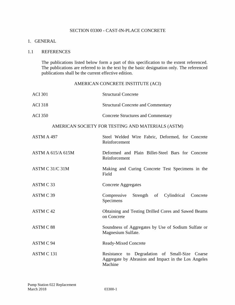
Pump Station 022 Replacement
March 2018 03300-1
SECTION 03300 - CAST-IN-PLACE CONCRETE
1. GENERAL
1.1 REFERENCES
The publications listed below form a part of this specification to the extent referenced.
The publications are referred to in the text by the basic designation only. The referenced
publications shall be the current effective edition.
AMERICAN CONCRETE INSTITUTE (ACI)
ACI 301 Structural Concrete
ACI 318 Structural Concrete and Commentary
ACI 350 Concrete Structures and Commentary
AMERICAN SOCIETY FOR TESTING AND MATERIALS (ASTM)
ASTM A 497 Steel Welded Wire Fabric, Deformed, for Concrete
Reinforcement
ASTM A 615/A 615M Deformed and Plain Billet-Steel Bars for Concrete
Reinforcement
ASTM C 31/C 31M Making and Curing Concrete Test Specimens in the
Field
ASTM C 33 Concrete Aggregates
ASTM C 39 Compressive Strength of Cylindrical Concrete
Specimens
ASTM C 42 Obtaining and Testing Drilled Cores and Sawed Beams
on Concrete
ASTM C 88 Soundness of Aggregates by Use of Sodium Sulfate or
Magnesium Sulfate.
ASTM C 94 Ready-Mixed Concrete
ASTM C 131 Resistance to Degradation of Small-Size Coarse
Aggregate by Abrasion and Impact in the Los Angeles
Machine
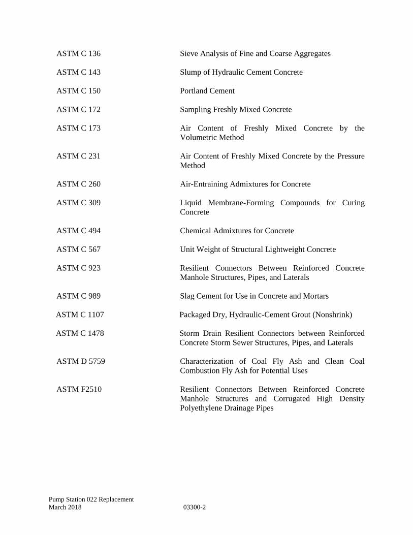
Pump Station 022 Replacement
March 2018 03300-2
ASTM C 136 Sieve Analysis of Fine and Coarse Aggregates
ASTM C 143 Slump of Hydraulic Cement Concrete
ASTM C 150 Portland Cement
ASTM C 172 Sampling Freshly Mixed Concrete
ASTM C 173 Air Content of Freshly Mixed Concrete by the
Volumetric Method
ASTM C 231 Air Content of Freshly Mixed Concrete by the Pressure
Method
ASTM C 260 Air-Entraining Admixtures for Concrete
ASTM C 309 Liquid Membrane-Forming Compounds for Curing
Concrete
ASTM C 494 Chemical Admixtures for Concrete
ASTM C 567 Unit Weight of Structural Lightweight Concrete
ASTM C 923 Resilient Connectors Between Reinforced Concrete
Manhole Structures, Pipes, and Laterals
ASTM C 989 Slag Cement for Use in Concrete and Mortars
ASTM C 1107 Packaged Dry, Hydraulic-Cement Grout (Nonshrink)
ASTM C 1478 Storm Drain Resilient Connectors between Reinforced
Concrete Storm Sewer Structures, Pipes, and Laterals
ASTM D 5759 Characterization of Coal Fly Ash and Clean Coal
Combustion Fly Ash for Potential Uses
ASTM F2510 Resilient Connectors Between Reinforced Concrete
Manhole Structures and Corrugated High Density
Polyethylene Drainage Pipes
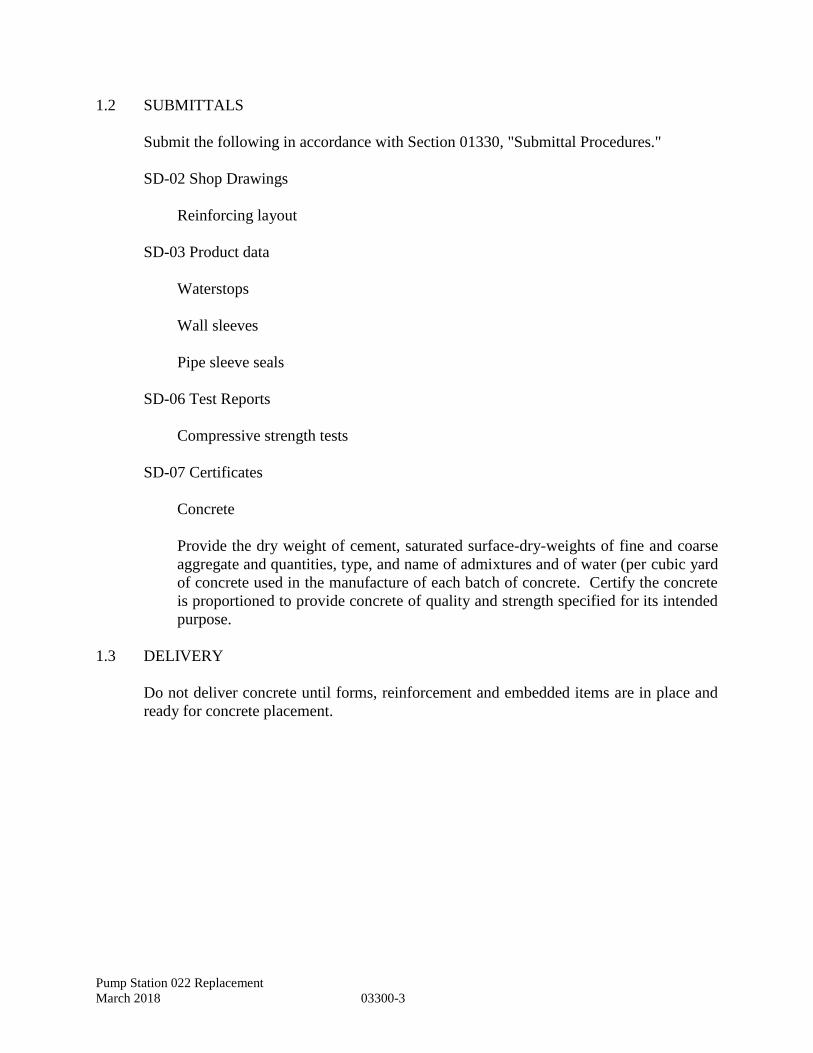
Pump Station 022 Replacement
March 2018 03300-3
1.2 SUBMITTALS
Submit the following in accordance with Section 01330, "Submittal Procedures."
SD-02 Shop Drawings
Reinforcing layout
SD-03 Product data
Waterstops
Wall sleeves
Pipe sleeve seals
SD-06 Test Reports
Compressive strength tests
SD-07 Certificates
Concrete
Provide the dry weight of cement, saturated surface-dry-weights of fine and coarse
aggregate and quantities, type, and name of admixtures and of water (per cubic yard
of concrete used in the manufacture of each batch of concrete. Certify the concrete
is proportioned to provide concrete of quality and strength specified for its intended
purpose.
1.3 DELIVERY
Do not deliver concrete until forms, reinforcement and embedded items are in place and
ready for concrete placement.
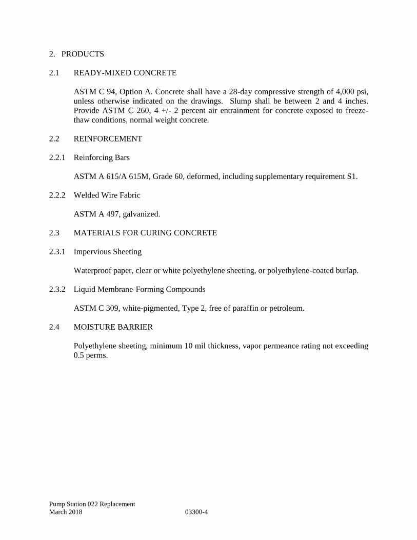
Pump Station 022 Replacement
March 2018 03300-4
2. PRODUCTS
2.1 READY-MIXED CONCRETE
ASTM C 94, Option A. Concrete shall have a 28-day compressive strength of 4,000 psi,
unless otherwise indicated on the drawings. Slump shall be between 2 and 4 inches.
Provide ASTM C 260, 4 +/- 2 percent air entrainment for concrete exposed to freeze-
thaw conditions, normal weight concrete.
2.2 REINFORCEMENT
2.2.1 Reinforcing Bars
ASTM A 615/A 615M, Grade 60, deformed, including supplementary requirement S1.
2.2.2 Welded Wire Fabric
ASTM A 497, galvanized.
2.3 MATERIALS FOR CURING CONCRETE
2.3.1 Impervious Sheeting
Waterproof paper, clear or white polyethylene sheeting, or polyethylene-coated burlap.
2.3.2 Liquid Membrane-Forming Compounds
ASTM C 309, white-pigmented, Type 2, free of paraffin or petroleum.
2.4 MOISTURE BARRIER
Polyethylene sheeting, minimum 10 mil thickness, vapor permeance rating not exceeding
0.5 perms.
Pump Station 022 Replacement
March 2018 03300-5
2.5 WALL SLEEVES AND SEALS
Conduits and pipes passing through concrete floors and walls shall be made with a wall
sleeve, unless otherwise noted on the plans.
2.5.1 Perpendicular Penetration Seals
Seals constructed of an assembly of synthetic rubber links connected with corrosion
resistant stainless steel bolts shall be used to seal the space between wall sleeve and
carrier pipe for pipes entering perpendicular to the concrete surface. When the bolts are
tightened, Delrin plastic pressure plates compress the rubber links to fill the annular space
between the pipe and the wall sleeve to form a watertight seal. Seals shall be
manufactured by Link Seal or approved equal.
2.5.2 Non-Perpendicular Penetration Seals
Rubber boot connectors with stainless steel bands meeting ASTM C 923, ASTM C 1478,
and ASTM F 2510, as applicable for the application, by Kor-N-Seal, PSX, or approved
equal shall be used for conduits and pipes passing through non-perpendicular
penetrations or where entering circular structures below grade. Place non-shrink grout in
annular space (inside and outside, as applicable) and finish flush with surface of concrete.
2.6 WATERSTOPS
All belowground concrete construction joints (vertical and horizontal) shall have
bentonite-type waterstops that have a 75 percent minimum bentonite content. Acceptable
waterstop is WATERSTOP-RX® by Volclay. Where a pipe, conduit, or sleeve is cast
into a concrete wall, roof or floor, a bentonite waterstop must be installed around the
outside of either the pipe or of the sleeve.
2.7 NONSHRINK GROUT
ASTM C 1107.
2.8 FORM MATERIALS
Provide metal, plywood, or hardboard forms capable of producing the required surface
without adverse effect on concrete. Do not use form coating that adversely affects
concrete surfaces or impairs subsequent applications to the concrete. Provide metal form
ties, factory-fabricated, removable or snap-off type that will leave holes less than 1/4 inch
deep and not more than one inch in diameter.
2.9 SPACERS, CHAIRS, BOLSTERS, TIES AND OTHER DEVICES
Galvanized steel or non-corroding material conforming to the Concrete Reinforcing Steel
institute (CRSI) “Manual of Standard Practice for Reinforced Concrete Construction.”
Pump Station 022 Replacement
March 2018 03300-6
2.10 CONCRETE MATERIALS:
Portland Cement: ASTM C 150, Type 1
Fly Ash: Fly ash conforming to ASTM D5759 may be used if required for ASR design
in accordance with ACI 318 and ACI 350.
Aggregates: ASTM C 33 for normal weight concrete. Provide aggregates from a single
source for exposed concrete
For exposed exterior surfaces, do not use fine or course aggregates that contain
substances that cause spalling.
Where aggregate are alkali-reactive us low alkali cement and use admixtures in
accordance with ACI 350, or use ASR resistance aggregate in accordance with
ACI 350.
Water: Potable.
Admixtures, General: provide concrete admixture that conform to ASTM C233 and that
contain no more than 0.1 percent chloride ions.
Air –Entraining Admixture: ASTM C 260, certified by manufacturer to be compatible
with other required admixtures.
Water-Reducing Admixture: ASTM C 494, Type A.
High-Range Water-Reducing Admixture: ASMT C 494, Type F or Type G.
Water-Reducing, Accelerating Admixture: ASTM C 494, Type E.
Water-Reducing, Retarding Admixture: ASTM C 494, Type D.
3. EXECUTION
3.1 FORMS
ACI 301.
3.2 PLACING REINFORCEMENT
ACI 301. Provide bars, wire fabric, including wire ties, supports, and other devices
necessary to install and secure the reinforcement.
Pump Station 022 Replacement
March 2018 03300-7
3.3 SETTING MISCELLANEOUS MATERIAL
Place and secure anchors and bolts, waterstops, pipe sleeves, conduits, and other such
items in position before concrete placement in accordance with manufacturer’s
recommendations. Plumb anchor bolts and check location and elevation.
3.3.1 Wall sleeves and seals
Temporarily fill voids in sleeves with readily removable material to prevent the entry of
concrete. After installation of carrier pipe and pipe seal, place non-shrink grout in
annular space (both faces) and finish flush with surface of concrete.
3.3.2 Embedded pipes and conduits
Comply with ACI 318, Article 6.3.5.1 and Article 6.3.5.2. Conduits and embedded pipes
shall not be spaced closer than 3 diameters or widths on center. The largest conduit size
shall not be larger in outside dimension than 1/3 the overall thickness of the concrete
member.
3.4 EDGE AND CORNER TREATMENTS
Chamfer edges are required for all joints and exposed edges whether indicated or not.
Slope for wet well fillets shall be as noted in the plans.
3.5 FLOOR PENETRATION CURBING
All pipe and conduit 3 inch and smaller passing through the floor shall have a 3 inch high
concrete grout curbing around it. Provide 1 inch chamfer on all exposed edges.
3.6 INSTALLATION OF MOISTURE BARRIER
Provide beneath the on-grade concrete floor slab. Lap 4 inches minimum, and seal laps
and patches with pressure-sensitive adhesive or tape 2 inches wide, minimum.
3.7 CONCRETE PLACEMENT
Deliver concrete from mixer to forms continuously until approved unit of operation is
completed. Provide scaffolding, ramps and walkways so that personnel and equipment
are not supported by in-place reinforcement. Placing will not be permitted when sun,
heat, wind, or limitations of facilities furnished by the Contractor prevent proper
consolidation, finishing and curing. Deposit concrete as close as possible to its final
position in the forms. When a vertical drop greater than 8 feet is authorized, provide
equipment to prevent segregation. Regulate depositing of concrete so that it will be
consolidated in horizontal layers not more than 12 inches thick. Place slabs in one layer.
Screed concrete to provide levels and profiles indicated.
Pump Station 022 Replacement
March 2018 03300-8
3.8 CONSOLIDATION
Immediately after placing, consolidate each layer of concrete by internal vibrators, except
for slabs 4 inches or less. Use vibrators adequate in effectiveness and number to properly
consolidate the concrete; keep a spare vibrator at the job site during placing operations.
3.9 WEATHER LIMITATIONS
Use special protection measures as approved by Engineer, when freezing temperatures
are anticipated before expiration of the specified curing period (minimum 48 hours).
Temperature of concrete placed during warm weather shall not exceed 85 degrees F
except where an approved retarder is used.
3.10 CONSTRUCTION JOINTS
Locate where indicated or approved. Where concrete work is interrupted by weather, end
of work shift or other type of delay, location and type of construction joint shall be
subject to approval of the Engineer.
3.11 SURFACE FINISHES
ACI 301 for repair and finish. Slope floors uniformly to drains where drains are provided
or indicated. At a minimum, provide the following finishes:
A. Rough Form - Exterior walls below grade
B. Smooth Form - Interior wet well walls
C. Smooth Rubbed - Interior walls, beams, edges of slab, housekeeping and
equipment pads, and exterior wall exposed to view.
D. Float Finish - Top of interior slabs
E. Broom Finish - Porch, steps, walks and other exterior pedestrian surfaces
above grade
F. Pavement Finish - Exterior concrete driveways and vehicular access slabs
3.11.1 Floated Finish
Place, consolidate, and immediately strike off concrete to obtain proper contour, grade,
and elevation before bleedwater appears. Permit concrete to attain a set sufficient for
floating and supporting the weight of the finisher and equipment. When bleedwater is
present prior to floating the surface, drag excess water off or remove by absorption with
porous materials. Do not use dry cement to absorb bleedwater. Surface shall be level to
within 1/4 inch in 10 feet where floor drains are not provided.
Pump Station 022 Replacement
March 2018 03300-9
3.11.2 Broomed Finished
Provide for exterior walks, platforms, patios, and ramps, unless otherwise indicated.
Provide a floated finish, then finish with a flexible bristle broom. Permit surface to
harden sufficiently to retain the scoring or ridges. Broom transverse to traffic or at right
angles to the slope of the slab.
3.11.3 Pavement Finish
Screed the concrete with a template advanced with a combined longitudinal and
crosswise motion. Maintain a slight surplus of concrete ahead of the template. After
screeding, float the concrete longitudinally. Use a straight edge to check slope and
flatness; correct and refloat as necessary. Obtain final finish by belting. Lay belt flat on
the concrete surface and advance with a sawing motion; continue until a uniform but
gritty nonslip surface is obtained. Round edges and joints with an edger having a radius
of 1/8 inch.
3.12 CURING AND PROTECTION
ACI 301. Preserve moisture, protect from temperature extremes, wind and rain, and from
mechanical injury.
3.13 COATINGS
Coatings shall be in accordance with Section 09900, “Paints and Coatings.”
3.14 SETTING BASE PLATES AND BEARING PLATES
Clean and dampen concrete surface before grouting. Set plate or equipment base to line
and elevation. Provide grout at least 3/4 inches thick. Surfaces in contact with grout
shall be free of oil and grease.
3.15 FIELD QUALITY CONTROL
3.15.1 Sampling
ASTM C 172. Collect samples of fresh concrete to perform tests specified. ASTM C
31/C 31M for making test specimens.
3.15.2 Testing
3.15.2.1 Slump Tests
ASTM C 143. Take concrete samples during concrete placement. Perform tests at
commencement of concrete placement, when test cylinders are made, and for each batch
(minimum) or every 20 cubic yards (maximum) of concrete.
Pump Station 022 Replacement
March 2018 03300-10
3.15.2.2 Air Content
ASTM C 173 or ASTM C 231 for normal weight concrete. Test air-entrained concrete
for air content at the same frequency as specified for slump tests.
3.15.2.3 Temperature Tests
Test the concrete delivered and the concrete in the forms. Perform tests in hot or cold
weather conditions (below 50 degrees F and above 80 degrees F) for each batch
(minimum) or every 20 cubic yards (maximum) of concrete, until the specified
temperature is obtained, and whenever test cylinders and slump tests are made.
3.15.2.4 Compressive Strength Tests
ASTM C 39. Make two test cylinders for each set of tests in accordance with ASTM C
31/C 31M. Precautions shall be taken to prevent evaporation and loss of water from the
specimen. Test two cylinders at 28 days. Samples for strength tests of each mix design
of concrete placed each day shall be taken not less than once a day, nor less than once for
each 100 cubic yards of concrete, nor less than once for each 500 square feet of surface
area for slabs or walls. Each strength test result shall be the average of two cylinders from
the same concrete sample tested at 28 days. If the average of any three consecutive
strength test results is less than f'c or if any strength test result falls below f'c by more
than 500 psi, take a minimum of three ASTM C 42 core samples from the in-place work
represented by the low test cylinder results and test. Remove concrete not meeting
strength criteria and provide new acceptable concrete at no additional expense to the
Owner. Repair core holes with nonshrink grout. Match color and finish of adjacent
concrete.
END OF SECTION
Pump Station 022 Replacement
March 2018 03400-1
SECTION 03400 - PRECAST CONCRETE WET WELLS AND VALVE VAULT
1. GENERAL
1.1 SUMMARY
A. This section addresses the work related to furnishing and installing all
supervision, labor, materials and equipment in the work for Precast Concrete
Structural Sections, pipe connectors and accessories, placement procedures,
and finishes.
B. Related Sections
02315 Excavation and Fill 03300 Cast-in-Place Concrete
1.2 SUBMITTALS
A. Submit shop drawings and manufacturers data in accordance with the provisions
of Division I, General Provisions, and Section 01330 — Submittal Procedures.
B. Copy of Certificate or Report showing that the Precast Concrete Manufacturer
conforms to Article 1.4 of this Specification Section.
C. Calculations and Details of Precast Concrete Structural Sections, including
buoyancy calculations to be provided and sealed by A Professional Engineer,
registered in the Commonwealth of Virginia, employed by the Manufacturer
showing or charting the following:
l) Manufacturer's Part No. or Catalogue No.
2) Inside diameter and height excluding base slab.
3) Wall thickness and base or top thickness where applicable.
4) Handling weight and lifting hole or loop description and locations.
5) Wire size, spacing, location, and steel area provided per vertical foot.
6) Reinforcing bar grade, size, spacing and location.
7) Design load for Flat Slab.
8) Concrete mix number and design strength.
9) Height, width, slope and annular space of the tongue & groove.
Pump Station 022 Replacement
March 2018 03400-2
D. Pipe Connector Details, Material Specification and pipe installation procedure.
E. Joint Material Details and Material Specifications. Calculations showing the
flexible joint sealant cross section is greater than the joints annular space times
its height shall be provided when butyl rope internal seals are proposed.
F. Lifting Device and Hole Details that include design loads.
G. Structural analysis and design calculations for Flat Slab Top Precast
Components, performed in accordance with the References of this
Specification, showing that allowable stresses will not be exceeded. All
calculations must be sealed by a Professional Engineer, registered in the
Commonwealth of Virginia, employed by the Precast Concrete Manufacturer.
H. Calculations or test results verifying that the lifting device components and holes
are designed in accordance with OSHA Standard 1926.704.
I. Concrete 28 day compression strength results for every day production of
Precast Components for the project was performed, showing the required
strength according to the guidelines established in ACI 318.
J. Reinforcing and Cement mill reports for materials used in the Manufacture of
Precast Components for this project.
K. The above test reports for similar Precast Components recently produced,
submitted prior to production of Precast Components for this project.
1.3 REFERENCES
A. The publications listed below form a part of this specification to the extent
referenced. The publications are referred to in the text by basic designation
only. The referenced publications shall be the current effective edition.
B. Pre-stressed Concrete Institute (PCI)
1) PCI—MNL 116 Manual for Quality Control for Plants and Production
of Precast and Prestressed Concrete Products.
2) PCI — MNL 120 Design Handbook Precast and Prestressed Concrete.
C. National Precast Concrete Association (NPCA)
1) Quality Control Manual for Precast Concrete Plants.
D. American Society for Testing and Materials
1) ASTM A82 — Standard Specifications for Steel Wire, Plain, for
Pump Station 022 Replacement
March 2018 03400-3
Concrete Reinforcement.
2) ASTM A416 — Standard Specifications for Steel Strand, Uncoated
Seven- Wire for Prestressed Concrete.
3) ASTM A615 — Standard Specifications for Deformed and Plain
Carbon- Steel Bars for Concrete Reinforcement.
4) ASTM C33 — Standard Specifications for Concrete Aggregates.
5) ASTM C260 – Standard Specifications for Air-Entraining Admixtures
for Concrete.
6) ASTM C361 — Standard Specifications for Reinforced Concrete Low-
Head Pressure Pipe.
7) ASTM C478 — Standard Specifications for Precast Reinforced
Concrete Manhole Sections.
8) ASTM C494 — Standard Specifications for Chemical Admixtures for
Concrete.
9) ASTM C857 — Practice for Minimum Structural Design Loading for
Underground Precast Concrete Utility Structures.
10) ASTM C881 — Standard Specifications for Epoxy-Resin-Base
Bonding Systems for Concrete.
11) ASTM C890 — Standard Practice for Minimum Structural Design
Loading for Monolithic or Sectional Precast Concrete Water and
Wastewater Structures.
12) ASTM C891 — Standard Practice for Installation of Underground
Precast Concrete Utility Structures.
13) ASTM C923 — Standard Specifications for Resilient Connectors
between Reinforced Concrete Manhole Structures, Pipes and Laterals.
14) ASTM C990 — Standard Specifications for Joints for Concrete Pipe,
Manholes and Precast Box Sections Using Preformed Flexible Joint
Sealants.
15) ASTM C1037 — Practice for Inspection of Underground Precast
Concrete Utility Structures.
Pump Station 022 Replacement
March 2018 03400-4
E. American Association of State Highway and Transportation Officials
(AASHTO)
1) AASHTO M198 — Standard Specification for Joints for Concrete
Pipe, Manholes, and Precast Box Sections Using Preformed Flexible Joint Sealants.
F. American Concrete Institute (ACI)
1) ACI 318 — Building Code Requirements for Structural Concrete and
Commentary.
2) ACI 350 — Code Requirements for Environmental Engineering
Concrete Structures and Commentary.
G. Occupational Safety and Health Administration (OSHA)
1) Standard 1926.704 — Requirements for Precast Concrete Submittals.
1.4 QUALIFICATIONS
A. The Precast Manufacturer shall comply with one of the following
requirements:
1) Manufacture Precast Components for the project in a plant certified in
the Prestressed Concrete Institute's (PCI) Plant Certification Program.
2) Manufacture Precast Components for the project in a plant certified in
the National Precast Concrete Association's (NPCA) Plant Certification
Program.
3) Retain an independent testing or consulting engineering firm approved
by the City of Hampton for Precast Plant Inspection. The basis for Plant
Inspection shall be the National Precast Concrete Association Quality
Control Manual or the Manual for Quality Control for Plants and
Production of Precast and Prestressed Concrete Products. The above
firm shall inspect the Precast Plant two weeks prior to and at one week
intervals during production of materials for this project and issue a
report, certified by a Professional Engineer, registered in the
Commonwealth of Virginia, that materials, methods, products, and
quality control meet the Requirements of the above quality control
manuals. Tests and inspections shall be paid by the CONTRACTOR.
B. Concrete compressive strength testing shall be performed in a laboratory
inspected by the CCRL of the National Bureau of Standards. Testing shall be
performed by Grade I ACI Certified Laboratory Technicians or by Level I PCI
Certified Technicians. Testing shall be paid by the CONTRACTOR.
Pump Station 022 Replacement
March 2018 03400-5
1.5 QUALITY
A. The manufacturer shall be responsible for the performance of all acceptance tests
as specified herein and in ASTM C478. In addition, any or all precast concrete
products to be installed under this Contract may be inspected at the plant for
compliance with these Specifications by the City of Hampton, by an
independent testing laboratory provided by the City of Hampton, or by other
representative of the City of Hampton. The CONTRACTOR shall require the
manufacturer’s cooperation in these inspections. The cost of inspection of all
products approved for this Contract will be borne by the CONTRACTOR.
B. Care shall be taken in shipping, handling, and installation to avoid damaging
the products. Any products damaged in shipment shall be replaced as directed
by the City of Hampton.
C. Inspections of the products will also be made by representatives of the City of
Hampton after delivery and after installation. The products shall be subject to
rejection at any time on account of failure to meet any of the Specification
requirements, even though they may have been accepted as satisfactory at the
place of manufacture. Products rejected after delivery shall be marked for
identification and shall be removed immediately from the work site.
D. Any precast concrete product showing a crack or damage or which has received
a blow that may have caused an incipient fracture, even though such fracture is
barely visible, shall be marked as rejected and immediately removed from the
work site. The City of Hampton’s opinion regarding such observations and
rejections shall be final.
1.6 INSPECTION, TEST REPORTS, MARKINGS AND SUBMITTALS
A. All precast concrete products to be installed under this contract shall be
inspected and tested at the place of manufacture to verify compliance with the
Specifications and Drawings.
B. The manufacturer shall perform factory testing as specified herein. Copies of
test reports shall be submitted to the City of Hampton before the product is
shipped to the project.
In the event that any of the test results fail to meet the Specifications, no
products represented by such tests shall be shipped to the job site and shall be
subject to rejection. The CONTRACTOR may perform additional tests upon
the products represented by the failed tests if he desires to verify the accuracy
of the original tests. The ENGINEER will review the test results and advise the
City of Hampton regarding the suitability of the products.
Pump Station 022 Replacement
March 2018 03400-6
Products, which have been rejected by the City of Hampton, shall not be
shipped to the site or shall be removed from the site of the work by the
CONTRACTOR and replaced with products, which meet these Specifications
and Drawings.
E. Prior to the shipment of each product to the site, the CONTRACTOR shall submit
to the City of Hampton test reports and certifications as described below duly
certified by the manufacturer’s approval testing facility representative or an
independent certified testing laboratory demonstrating full compliance with the
Specifications and Drawings.
F. An original plus two copies of the following shall be submitted to the City of
Hampton.
1) The name, address, and phone number of the product manufacturer and
location of the plant at which it was manufactured.
2) Certification and certified test reports for each product (by number) of
the tests performed on concrete and concrete cores showing the results
of the tests.
G. Imperfections in and minor damage to the concrete may be repaired with epoxy
mortar subject to the approval of the City of Hampton, after demonstration by
the manufacturer that strong and permanent repairs result. Repairs shall be
carefully inspected before final approval. Epoxy mortar shall be used for
repairs and shall have a minimum compressive strength of 4,000 psi at the end
of seven days, and 5,000 psi at the end of 28 days when tested in three-inch by
six-inch cylinders stored in the standard manner. No repairs shall be made until
the imperfections or damage has been inspected by the City of Hampton, and
repairs authorized in writing. Repairs made prior to such authorization will be
cause for rejection of the component. Pieces proposed for repair at the factory
shall be set aside for periodic inspection at the factory by the City of Hampton.
Inspections will not be made more frequently than once per month. Rejected
pieces shall not be shipped to or used for the work.
H. Precast concrete structures may be rejected for any of the following reasons:
1) Exposure of any reinforcement, wires, positioning spacers or chairs used
to hold the reinforcement cage in position.
2) Reinforcing steel to be in excess of 1/2-inch out of the specified
position within cores.
3) Any shattering or flaking of concr ete.
4) Voids which can be detected on the interior and exterior surfaces
exceeding ¼-inch in depth.
Pump Station 022 Replacement
March 2018 03400-7
5) Unauthorized application of any repair or coating.
6) A deficiency greater than ¼ -inch from the specified wall thickness.
7) A variation from the specified internal diameter in excess of 1%.
8) Defects that indicate incorrect molding of concrete or any surface
defect indicating honeycomb or other voids.
9) Any of the following cracks:
a. A crack having a width of 0.005 inches to 0.01 inches throughout
a continuous length of 36 inches or more.
b. A crack having a width of 0.01 inches to 0.03 inches or more
throughout a continuous length of 12 inches or more.
c. Any crack greater than 0.005 inches extending through the wall
and having a length in excess of the wall thickness.
d. Any crack showing two visible lines of separation for a
continuous length of two feet or more, or an interrupted length
of three feet or more anywhere in evidence both inside and
outside.
e. Any crack anywhere greater than 0.03 inches in width.
2. PRODUCTS.
2.1 MATERIALS
Antimicrobial Additive:
Antimicrobial additive, ConmicShield®, shall be used to render the concrete
uninhabitable for bacteria growth, where indicated on the plans. The liquid
antibacterial additive shall be an EPA registered material and the registration
number shall be submitted for approval prior to use in the project. The amount to
be used shall be as recommended by the manufacturer of the antibacterial additive.
This amount shall be included in the total water content of the concrete mix
design. The additive shall be added into the concrete mix water to insure even
distribution of the additive throughout the concrete mixture
A. Concrete shall conform to ASTM C478 and as follows:
1) Compressive strength: 5000 psi minimum at 28 days.
2) Air Content: 6% +/- 2%.
3) Alkalinity: Minimum of 50% calcium carbonate equivalent for bases,
risers, and cones.
4) Cementitious Materials: Minimum of 470 pounds per CY
Pump Station 022 Replacement
March 2018 03400-8
5) Coarse Aggregates: ASTM C33. Sound, Crushed, Angular Limestone.
Smooth or rounded stone shall not be used.
6) Fine Aggregates: ASTM C33. Free from organic impurities.
7) Chemical Admixtures: ASTM C494. Calcium Chloride or admixtures
containing calcium chloride shall not be used.
8) Air Entraining Admixtures: ASTM C260.
B. Reinforcing steel shall be ASTM A615 grade 60 deformed bar, ASTM A82 wire or ASTM A 185 welded wire fabric.
C. Lift loops shall be ASTM A416 steel strand. Lifting loops made from deformed
bars are not allowed.
D. Flexible Joint Sealants shall be butyl rubber based conforming to AASHTO M-
198, Type B - Butyl Rubber and as follows: maximum of 1% volatile matter
and suitable for application temperatures between 10 and 100 degrees F.
E. The outside of all below-grade joints shall be sealed with an eight-inch-side, adhesive butyl rubber sealant strip with Ethylene Propylene Diene Monomer
(E.P.D.M.) rubber backing. (ASTM C-990-98, Paragraph 6.2) The strip shall be installed only after the non-shrink grout has cured at least 72 hours and the
surface has been prepared and primed in accordance with the manufacturer’s printed directions.
1) CONTRACTOR shall obtain concurrence of City of Hampton’s Inspector regarding the adequacy of concrete surface preparation before
applying butyl rubber sealant strip.
F. Epoxy Gels for interior patching of wall penetrations shall be a 2-component, solvent-free, moisture-insensitive, high modulus, high-strength, structural
epoxy paste adhesive meeting ASTM C-881, Type I and II, Grade 3, Class B and
C, Epoxy Resin Adhesive.
Pump Station 022 Replacement
March 2018 03400-9
2.2 COMPONENTS
A. Precast Component Fabrication and Manufacture shall be as described in this
paragraph and as described in the paragraphs for the specific components.
1) Precast Manufacturing shall be in conformance with ASTM C478.
Wall and inside slab finishes resulting horn casting against forms
standard for the industry will be acceptable. Exterior slab surfaces
shall have a float finish. Small surface holes, normal color variations,
normal form joint marks, and minor depressions, chips and spalls will
be tolerated. Dimensional tolerances shall be those set forth in the
appropriate References and specified below.
2) Joint Surfaces between Bases and Risers shall be manufactured to the joint surface design and tolerance requirements of ASTM C361. The
maximum slope of the vertical surface shall be 2°. The maximum annular space at the base of the joint shall be 0.10 inches. The minimum
height of the joint shall be four inches.
3) Lift Inserts and Holes shall be sized for a precision fit with the lifting devices, shall comply with OSHA 1926.704, and shall not penetrate through the structure wall.
B. Precast Base Sections shall be cast monolithically without construction joints or
with an approved galvanized or PVC waterstop in the cold joint between the base slab and the walls. The width of the base extensions on Extended Base Structures
shall be no less than the base slab thickness. Base section shall incorporate base fillets shown on contract drawings.
C. Precast Riser Sections shall have a minimum height of 16 inches. Section
heights shall be configured to accommodate locations of pipe penetrations.
Penetrations shall not interfere with joint seal or compromise the joints
between precast components.
D. Precast Flat Slab Top Sections shall be designed for HS-20 traffic loadings as
defined in ASTM C890. Items to be cast into Special Flat Slab Tops shall be
sized to fit within the structure ID and the top and bottom surfaces.
E. Pipe to Precast Structure Connectors shall conform to ASTM C923. The location
of the pipe connectors shall vary from the location shown on the Project Plans no more than 1/2 inch vertically and 5 degrees horizontally.
F. Joints between Precast Components shall be sealed internally between the
tongue and the groove and additionally around the external perimeter as follows:
1) External Seals shall consist of an E.P.D.M. rubber backed flat butyl rubber sheet no less than 1/16-inch thick and eight inches wide applied
to the outside perimeter of the joint.
Pump Station 022 Replacement
March 2018 03400-10
2) Internal Seals shall consist of a plastic or paper-backed butyl rubber
rope having a cross-sectional area no less than the annular space times the height of the joint.
G. Lifting devices for handling Precast Components shall be provided by the
Precast Manufacturer and shall comply with OSHA Standard 1926.704.
2.3 CONFIGURATION
A. Precast structures are to be constructed as shown on the drawings.
B. The number of joints shall be minimized.
2.4 MANUFACTURERS
A. Fabricators:
1) Plant-precast concrete products for below grade construction
a. Concrete Pipe & Precast, LLC
b. Oldcastle Precast
c. Coastal Precast Systems
d. Manufacturer subject to compliance with requirements and approved
by the City of Hampton.
3. EXECUTION.
3.1 EXAMINATION
A. Inspect Precast Structure Components prior to unloading from the delivery
truck.
3.2 PREPARATION
A. Product Delivery, Storage, and Handling: Coordinate delivery with the
manufacturer, handle and store the Precast Components in accordance with
ASTM C891 and the manufacturer's recommendations using methods that will
prevent damage to the components and their joint surfaces.

Pump Station 022 Replacement
March 2018 03400-11
3.3 PLACING STRUCTURE SECTIONS
A. Excavate to the required depth and remove materials that are unstable or
unsuitable for a good foundation. Prepare a level, compacted foundation
extending six inches beyond the precast structure and any added extended base.
B. Set base plumb and level.
C. Set risers, taking particular care to clean, prepare and seal joints.
D. After joining structure sections, apply the butyl sealant sheet around the outside
perimeter of the joint.
E. Lift Holes leaving less than two inches of wall thickness shall be plugged from
the outside using a sand cement mortar, then covered with butyl sealant sheet. Lift Holes penetrating the wall shall be additionally sealed with an interior
application of an epoxy gel 1/8-inch thick extending two inches beyond the penetration.
F. Perform the final finishing of the precast structure’s interior by filling all chips or fractures greater than 1/2-inch in length, width or depth and depressions more than 1/2- inch deep with a sand cement mortar. Do not fill the joints between the precast concrete sections. Clean the interior of the structure, removing all dirt, spills or other foreign matter.
END OF SECTION

Pump Station 022 Replacement
March 2018 03400-12
This Page Intentionally Left Blank

Pump Station 022 Replacement
March 2018 03410 - 1
SECTION 03410 – PRECAST STRUCTURAL CONCRETE BUILDINGS
1. GENERAL
1.1 RELATED DOCUMENTS
A. Drawings and general provisions of the Contract, including General and Supplementary
Conditions and Division 01 Specification Sections, apply to this Section.
1.2 SUMMARY
A. Section Includes:
1. Precast structural concrete.
B. Related Sections:
1. Division 03 Section "Cast-in-Place Concrete" for concrete topping and placing
connection anchors in concrete.
2. Division 05 Section "Miscellaneous Metals and Fabrications" for kickers and
other miscellaneous steel shapes.
3. Division 08 Section “Doors and Frames” for door opening and frame
requirements.
1.3 DEFINITION
A. Design Reference Sample: Sample of approved precast structural concrete color, finish,
and texture, preapproved by Architect.
1.4 PERFORMANCE REQUIREMENTS
A. Structural Performance: Precast structural concrete units and connections shall
withstand design loads indicated within limits and under conditions indicated on the
design drawings.
1.5 SUBMITTALS
A. Product Data: For each type of product indicated.
B. Design Mixtures: For each precast concrete mixture. Include compressive strength and
water-absorption tests.

Pump Station 022 Replacement
March 2018 03410 - 2
C. Shop Drawings: Include member locations, plans, elevations, dimensions, shapes and
sections, openings, support conditions, and types of reinforcement, including special
reinforcement. Detail fabrication and installation of precast structural concrete units.
1. Indicate joints, reveals, and extent and location of each surface finish.
2. Indicate separate face and backup mixture locations and thicknesses.
3. Indicate welded connections by AWS standard symbols. Show size, length, and
type of each weld.
4. Detail loose and cast-in hardware, lifting and erection inserts, connections, and
joints.
5. Indicate locations, tolerances, and details of anchorage devices to be embedded in
or attached to structure or other construction.
6. Include and locate openings larger than by 10 inches (250 mm). (To include door
openings, vent openings, louver openings, etc.)
7. Indicate location of each precast structural concrete unit by same identification
mark placed on panel.
8. Indicate relationship of precast structural concrete units to adjacent materials.
9. Indicate estimated camber for precast floor slabs with concrete toppings.
10. Indicate shim sizes and grouting sequence.
11. Design Modifications: If design modifications are proposed to meet performance
requirements and field conditions, submit design calculations and Shop Drawings.
Do not adversely affect the appearance, durability, or strength of units when
modifying details or materials and maintain the general design concept.
D. Delegated-Design Submittal: For precast structural concrete buildings indicated to
comply with performance requirements and design criteria, including concrete mix
design, concrete test reports, erection drawings, production shop drawings and analysis
data signed and sealed by the qualified professional engineer registered in the state of
Virginia responsible for their preparation.
E. Qualification Data: For Installer, fabricator, testing agency.
F. Welding certificates.
G. Material Certificates: For the following, from manufacturer:
1. Cementitious materials.
2. Reinforcing materials and prestressing tendons.
3. Admixtures.
4. Bearing pads.
5. Structural-steel shapes and hollow structural sections.
H. Material Test Reports: For aggregates.
I. Source quality-control reports.
J. Field quality-control and special inspection reports.
Pump Station 022 Replacement
March 2018 03410 - 3
1.6 QUALITY ASSURANCE
A. Fabricator Qualifications: A firm that assumes responsibility for engineering precast
structural concrete units to comply with performance requirements. Responsibility
includes preparation of Shop Drawings and comprehensive engineering analysis by a
qualified professional engineer.
1. Participates in PCI's Plant Certification program and is designated a PCI-certified
plant.
B. Installer Qualifications: A precast concrete erector qualified, as evidenced by PCI's
Certificate of Compliance, to erect Category S1 - Simple Structural Systems and
Category S2 - Complex Structural Systems.
C. Testing Agency Qualifications: Qualified according to ASTM C 1077 and
ASTM E 329 for testing indicated.
D. Design Standards: Comply with ACI 318 (ACI 318M) and design recommendations in
PCI MNL 120, "PCI Design Handbook - Precast and Prestressed Concrete," applicable
to types of precast structural concrete units indicated.
E. Quality-Control Standard: For manufacturing procedures and testing requirements,
quality-control recommendations, and dimensional tolerances for types of units
required, comply with PCI MNL 116, "Manual for Quality Control for Plants and
Production of Structural Precast Concrete Products."
F. Welding Qualifications: Qualify procedures and personnel according to the following:
1. AWS D1.1/D.1.1M, "Structural Welding Code - Steel."
2. AWS D1.4, "Structural Welding Code - Reinforcing Steel."
G. Fire-Resistance Calculations: Where indicated, provide precast structural concrete units
whose fire resistance meets the prescriptive requirements of authorities having
jurisdiction or has been calculated according to ACI 216.1/TMS 0216.1, "Standard
Method for Determining Fire Resistance of Concrete and Masonry Construction
Assemblies," and PCI MNL 124, "Design for Fire Resistance of Precast Prestressed
Concrete," and is acceptable to authorities having jurisdiction.
H. Preinstallation Conference: Conduct conference at Project site.
1.7 DELIVERY, STORAGE, AND HANDLING
A. Support units during shipment on nonstaining shock-absorbing material in same
position as during storage.
B. Store units with adequate bracing and protect units to prevent contact with soil, to
prevent staining, and to prevent cracking, distortion, warping or other physical damage.
Pump Station 022 Replacement
March 2018 03410 - 4
1. Store units with dunnage across full width of each bearing point unless otherwise
indicated.
2. Place adequate dunnage of even thickness between each unit.
3. Place stored units so identification marks are clearly visible, and units can be
inspected.
C. Handle and transport units in a position consistent with their shape and design in order
to avoid excessive stresses that would cause cracking or damage.
D. Lift and support units only at designated points shown on Shop Drawings.
1.8 COORDINATION
A. Furnish loose connection hardware and anchorage items to be embedded in or attached
to other construction before starting that Work. Provide locations, setting diagrams,
templates, instructions, and directions, as required, for installation.
1.9 DESIGN REQUIREMENTS
A. General:
1. Precast Components: The manufacturer shall complete the design, including
calculations and detailing, for all precast components specified on the Contract
Drawings. Design shall be based on preliminary design criteria and conditions
provided on the Drawings and in the Specifications. The manufacturer shall
perform the complete design assuring that the manufacturing, transportation and
erection process are compatible with the Contract Drawings and Specifications.
2. Erection: The manufacturer’s designer shall consider erection of the precast
components including calculations and details for guying, staying, and shoring all
precast components to assure structural stability during the construction stage and
before all permanent structural connections are completed. Provide in the
erection plan for removal, replacement, and relocation of guying, bracing, and
shoring before all permanent precast structural connections are completed. The
manufacturer’s registered professional engineer shall retain responsibility for the
erection design.
3. Design of precast components and connections shall be prepared under the direct
supervision of the manufacturer’s professional engineer registered in the state of
Virginia with approval by the Engineer of Record (EOR).
4. The connection of Precast Components to non-precast components shall be
coordinated by the contractor and manufacturer with the contract drawings.
These connections and any modifications to the non-precast components shown
Pump Station 022 Replacement
March 2018 03410 - 5
on the contractor drawings to accommodate the precast components shall be
submitted for review by the Engineer of Record.
B. Design Criteria:
1. Design Loads:
a. All dead and live loads specified on the Contract Drawings.
b. All other loads specified for components, where applicable.
c. Initial handling and erection stress limits.
d. All precast components and connections to non-precast elements shall be
designed in accordance with the PCI Design Handbook.
e. All precast components shall have a minimum reinforcing in accordance
with ACI 318. Analysis of prestressed components shall include a check of
the shear reinforcing requirements at 0.1L, 0.2L, 0.25L and 0.3L, where L is
the component length.
C. Modifications:
1. All proposed modifications to the drawings and specifications shall be submitted
to the Architect and Engineer with complete design calculations and drawings.
2. The location of openings shall be shown on the drawings. Openings shall be
located and field drilled (or cut) by the trade requiring them after precast
components have been erected and grouted. Locations of all field cut openings
shall be reviewed and approved by the manufacturer prior to drilling or cutting.
3. Contractor is responsible for providing precast manufacturer will all necessary
information regarding openings, components, equipment, cast-in items to the
precast manufacturer.
D. Lifting Devices shall be designed and cast into the components to ensure safe and
efficient handling. Lifting devices shall be so arranged that they do not have to be
removed; or, if they must be removed, they shall be arranged so that they are readily
removed and any planned depressions in the concrete can be readily filled.
E. Lift loops and erection inserts shall be located so they are not objectable in the
completed structure with a minimum concrete or grout cover as specified in ACI 318
and the PCI Design Handbook. Inserts located in areas exposed to view shall be
recessed and patched with non-shrink, non-staining grout to match surrounding
concrete, or cover and protect in an approved manner.
Pump Station 022 Replacement
March 2018 03410 - 6
PART 2 - PRODUCTS
2.1 MANUFACTURERS
A. Fabricators:
1. Plant-precast concrete building
a. Smith-Midland
b. Manufacturer subject to compliance with requirements and approved by the
City of Hampton.
2.2 MOLD MATERIALS
A. Molds: Rigid, dimensionally stable, non-absorptive material, warp and buckle free, that
will provide continuous and true precast concrete surfaces within fabrication tolerances
indicated; nonreactive with concrete and suitable for producing required finishes.
1. Mold-Release Agent: Commercially produced liquid-release agent that will not
bond with, stain or adversely affect precast concrete surfaces and will not impair
subsequent surface or joint treatments of precast concrete.
B. Form Liners: Units of face design, texture, arrangement, and configuration indicated.
Furnish with manufacturer's recommended liquid-release agent that will not bond with,
stain, or adversely affect precast concrete surfaces and will not impair subsequent
surface or joint treatments of precast concrete.
C. Surface Retarder: Chemical set retarder, capable of temporarily delaying final
hardening of newly placed concrete mixture to depth of reveal specified.
2.3 REINFORCING MATERIALS
A. Reinforcing Bars: ASTM A 615/A 615M, Grade 60 (Grade 420), deformed.
B. Low-Alloy-Steel Reinforcing Bars: ASTM A 706/A 706M, deformed.
C. Steel Bar Mats: ASTM A 184/A 184M, fabricated from ASTM A 615/A 615M,
Grade 60 (Grade 420), deformed bars, assembled with clips.
D. Plain-Steel Welded Wire Reinforcement: ASTM A 185, fabricated from wire into flat
sheets.
E. Deformed-Steel Welded Wire Reinforcement: ASTM A 497/A 497M, flat sheet.
F. Supports: Suspend reinforcement from back of mold or use bolsters, chairs, spacers,
and other devices for spacing, supporting, and fastening reinforcing bars and welded
wire reinforcement in place according to PCI MNL 116.
Pump Station 022 Replacement
March 2018 03410 - 7
2.4 PRESTRESSING TENDONS
A. Pretensioning Strand: ASTM A 416/A 416M, Grade 250 (Grade 1720) or Grade 270
(Grade 1860), uncoated, 7-wire or ASTM A 886/A 886M, Grade 270 (Grade 1860),
indented, 7-wire, low-relaxation strand.
B. Unbonded Post-Tensioning Strand: ASTM A 416/A 416M, Grade 270 (Grade 1860),
uncoated, 7-wire, low-relaxation strand.
1. Coat unbonded post-tensioning strand with post-tensioning coating complying
with ACI 423.6 and sheath with polypropylene tendon sheathing complying with
ACI 423.6. Include anchorage devices and coupler assemblies.
C. Post-Tensioning Bars: ASTM A 722, uncoated high-strength steel bar.
2.5 CONCRETE MATERIALS
A. Portland Cement: ASTM C 150, Type I or Type III, gray, unless otherwise indicated.
1. For surfaces exposed to view in finished structure, mix gray with white cement, of
same type, brand, and mill source.
B. Supplementary Cementitious Materials:
1. Fly Ash: ASTM C 618, Class C or F, with maximum loss on ignition of 3
percent.
2. Metakaolin Admixture: ASTM C 618, Class N.
3. Silica Fume Admixture: ASTM C 1240, with optional chemical and physical
requirement.
4. Ground Granulated Blast-Furnace Slag: ASTM C 989, Grade 100 or 120.
C. Normal-Weight Aggregates: Except as modified by PCI MNL 116, ASTM C 33, with
coarse aggregates complying with Class 5S or Class 4S. Stockpile fine and coarse
aggregates for each type of exposed finish from a single source (pit or quarry) for
Project.
1. Face-Mixture-Coarse Aggregates: Selected, hard, and durable; free of material
that reacts with cement or causes staining; to match selected finish sample.
a. Gradation: Uniformly graded.
2. Face-Mixture-Fine Aggregates: Selected, natural or manufactured sand of same
material as coarse aggregate unless otherwise approved by Architect.
D. Coloring Admixture: ASTM C 979, synthetic or natural mineral-oxide pigments or
colored water-reducing admixtures, temperature stable, and nonfading.

Pump Station 022 Replacement
March 2018 03410 - 8
E. Water: Potable; free from deleterious material that may affect color stability, setting, or
strength of concrete and complying with chemical limits of PCI MNL 116.
F. Air-Entraining Admixture: ASTM C 260, certified by manufacturer to be compatible
with other required admixtures.
G. Chemical Admixtures: Certified by manufacturer to be compatible with other
admixtures and to not contain calcium chloride, or more than 0.15 percent chloride ions
or other salts by weight of admixture.
1. Water-Reducing Admixtures: ASTM C 494/C 494M, Type A.
2. Retarding Admixture: ASTM C 494/C 494M, Type B.
3. Water-Reducing and Retarding Admixture: ASTM C 494/C 494M, Type D.
4. Water-Reducing and Accelerating Admixture: ASTM C 494/C 494M, Type E.
5. High-Range, Water-Reducing Admixture: ASTM C 494/C 494M, Type F.
6. High-Range, Water-Reducing and Retarding Admixture: ASTM C 494/C 494M,
Type G.
7. Plasticizing and Retarding Admixture: ASTM C 1017/C 1017M.
H. Corrosion-Inhibiting Admixture: Commercially formulated, anodic inhibitor or mixed
cathodic and anodic inhibitor; capable of forming a protective barrier and minimizing
chloride reactions with steel reinforcement in concrete.
2.6 STEEL CONNECTION MATERIALS
A. Carbon-Steel Shapes and Plates: ASTM A 36/A 36M.
B. Carbon-Steel-Headed Studs: ASTM A 108, AISI 1018 through AISI 1020, cold
finished, AWS D1.1/D1.1M, Type A or B, with arc shields and with minimum
mechanical properties of PCI MNL 116.
C. Carbon-Steel Plate: ASTM A 283/A 283M.
D. Malleable-Iron Castings: ASTM A 47/A 47M.
E. Carbon-Steel Castings: ASTM A 27/A 27M, Grade 60-30 (Grade 415-205).
F. High-Strength, Low-Alloy Structural Steel: ASTM A 572/A 572M.
G. Carbon-Steel Structural Tubing: ASTM A 500, Grade B.
H. Wrought Carbon-Steel Bars: ASTM A 675/A 675M, Grade 65 (Grade 450).
I. Deformed-Steel Wire or Bar Anchors: ASTM A 496 or ASTM A 706/A 706M.
J. Carbon-Steel Bolts and Studs: ASTM A 307, Grade A (ASTM F 568M, Property
Class 4.6); carbon-steel, hex-head bolts and studs; carbon-steel nuts, ASTM A 563
(ASTM A 563M); and flat, unhardened steel washers, ASTM F 844.
Pump Station 022 Replacement
March 2018 03410 - 9
K. High-Strength Bolts and Nuts: ASTM A 325 (ASTM A 325M) or ASTM A 490
((ASTM A 490M),) Type 1, heavy hex steel structural bolts; heavy hex carbon-steel
nuts, ASTM A 563 (ASTM A 563M); and hardened carbon-steel washers, ASTM F 436
(ASTM F 436M).
1. Do not zinc coat ASTM A 490 (ASTM A 490M) bolts.
L. Zinc-Coated Finish: For exterior steel items and items indicated for galvanizing, apply
zinc coating by hot-dip process according to ASTM A 123/A 123M or
ASTM A 153/A 153M.
1. For steel shapes, plates, and tubing to be galvanized, limit silicon content of steel
to less than 0.03 percent or to between 0.15 and 0.25 percent or limit sum of
silicon and 2.5 times phosphorous content to 0.09 percent.
2. Galvanizing Repair Paint: High-zinc-dust-content paint with dry film containing
not less than 94 percent zinc dust by weight, and complying with DOD-P-21035B
or SSPC-Paint 20.
M. Shop-Primed Finish: Prepare surfaces of nongalvanized-steel items, except those
surfaces to be embedded in concrete, according to requirements in SSPC-SP 3, and shop
apply lead- and chromate-free, rust-inhibitive primer, complying with performance
requirements in MPI 79 or SSPC-Paint 25 according to SSPC-PA 1.
N. Welding Electrodes: Comply with AWS standards.
O. Precast Accessories: Provide clips, hangers, plastic or steel shims, and other
accessories required to install precast structural concrete units.
2.7 STAINLESS-STEEL CONNECTION MATERIALS
A. Stainless-Steel Plate: ASTM A 666, Type 304, of grade suitable for application.
B. Stainless-Steel Bolts and Studs: ASTM F 593, Alloy 304 or 316, hex-head bolts and
studs; stainless-steel nuts; and flat, stainless-steel washers. Lubricate threaded parts of
stainless-steel bolts with an antiseize thread lubricant during assembly.
C. Stainless-Steel-Headed Studs: ASTM A 276, with minimum mechanical properties of
PCI MNL 116.
Pump Station 022 Replacement
March 2018 03410 - 10
2.8 BEARING PADS
A. Provide one of the following bearing pads for precast structural concrete units as
recommended by precast fabricator for application:
1. Elastomeric Pads: AASHTO M 251, plain, vulcanized, 100 percent
polychloroprene (neoprene) elastomer, molded to size or cut from a molded sheet,
50 to 70 Shore, Type A durometer hardness, ASTM D 2240; minimum tensile
strength 2250 psi (15.5 MPa), ASTM D 412.
2. Random-Oriented, Fiber-Reinforced Elastomeric Pads: Preformed, randomly
oriented synthetic fibers set in elastomer. 70 to 90 Shore, Type A durometer
hardness, ASTM D 2240; capable of supporting a compressive stress of 3000 psi
(20.7 MPa) with no cracking, splitting, or delaminating in the internal portions of
pad. Test 1 specimen for every 200 pads used in Project.
3. Cotton-Duck-Fabric-Reinforced Elastomeric Pads: Preformed, horizontally
layered cotton-duck fabric bonded to an elastomer; 80 to 100 Shore, Type A
durometer hardness, ASTM D 2240; complying with AASHTO's "AASHTO
Load and Resistance Factor Design (LRFD) Bridge Specifications," Division II,
Section 18.10.2; or with MIL-C-882E.
4. Frictionless Pads: Tetrafluoroethylene, glass-fiber reinforced, bonded to
stainless- or mild-steel plate, of type required for in-service stress.
5. High-Density Plastic: Multimonomer, nonleaching, plastic strip.
2.9 GROUT MATERIALS
A. Sand-Cement Grout: Portland cement, ASTM C 150, Type I, and clean, natural sand,
ASTM C 144 or ASTM C 404. Mix at ratio of 1 part cement to 2-1/2 parts sand, by
volume, with minimum water required for placement and hydration.
B. Nonmetallic, Nonshrink Grout: Premixed, nonmetallic, noncorrosive, nonstaining grout
containing selected silica sands, portland cement, shrinkage-compensating agents,
plasticizing and water-reducing agents, complying with ASTM C 1107, Grade A for
drypack and Grades B and C for flowable grout and of consistency suitable for
application within a 30-minute working time.
C. Epoxy-Resin Grout: Two-component, mineral-filled epoxy resin;
ASTM C 881/C 881M, of type, grade, and class to suit requirements.
Pump Station 022 Replacement
March 2018 03410 - 11
2.10 CONCRETE MIXTURES
A. Prepare design mixtures for each type of precast concrete required.
1. Limit use of fly ash to 25 percent replacement of portland cement by weight and
granulated blast-furnace slag to 40 percent of portland cement by weight;
metakaolin and silica fume to 10 percent of portland cement by weight.
B. Design mixtures may be prepared by a qualified independent testing agency or by
qualified precast plant personnel at precast structural concrete fabricator's option.
C. Limit water-soluble chloride ions to maximum percentage by weight of cement
permitted by ACI 318 (ACI 318M) or PCI MNL 116 when tested according to
ASTM C 1218/C 1218M.
D. Normal-Weight Concrete Mixtures: Proportion face and backup mixtures or full-depth
mixtures, at fabricator's option by either laboratory trial batch or field test data methods
according to ACI 211.1, with materials to be used on Project, to provide normal-weight
concrete with the following properties:
1. Minimum Compressive Strength (28 Days): 4000 psi (34.5 MPa).
2. Maximum Water-Cementitious Materials Ratio: 0.45.
E. Water Absorption: 6 percent by weight or 14 percent by volume, tested according to
PCI MNL 116.
F. Lightweight Concrete Backup Mixtures: Proportion mixtures by either laboratory trial
batch or field test data methods according to ACI 211.2, with materials to be used on
Project, to provide lightweight concrete with the following properties:
1. Minimum Compressive Strength (28 Days): 4000 psi (27.6 MPa).
2. Unit Weight: Calculated equilibrium unit weight of 115 lb/cu. ft. (1842
kg/cu. m), plus or minus 3 lb/cu. ft. (48 kg/cu. m), according to ASTM C 567.
G. Add air-entraining admixture at manufacturer's prescribed rate to result in concrete at
point of placement having an air content complying with PCI MNL 116.
H. When included in design mixtures, add other admixtures to concrete mixtures according
to manufacturer's written instructions.
I. Concrete Mix Adjustments: Concrete mix design adjustments may be proposed if
characteristics of materials, Project conditions, weather, test results, or other
circumstances warrant.

Pump Station 022 Replacement
March 2018 03410 - 12
2.11 MOLD FABRICATION
A. Molds: Accurately construct molds, mortar tight, of sufficient strength to withstand
pressures due to concrete-placement operations and temperature changes and for
prestressing and detensioning operations. Coat contact surfaces of molds with release
agent before reinforcement is placed. Avoid contamination of reinforcement and
prestressing tendons by release agent.
1. Place form liners accurately to provide finished surface texture indicated. Provide
solid backing and supports to maintain stability of liners during concrete
placement. Coat form liner with form-release agent.
B. Maintain molds to provide completed precast structural concrete units of shapes, lines,
and dimensions indicated, within fabrication tolerances specified.
1. Form joints are not permitted on faces exposed to view in the finished work.
2. Edge and Corner Treatment: Uniformly chamfered or radiused.
2.12 FABRICATION
A. Cast-in Anchors, Inserts, Plates, Angles, and Other Anchorage Hardware: Fabricate
anchorage hardware with sufficient anchorage and embedment to comply with design
requirements. Accurately position for attachment of loose hardware, and secure in
place during precasting operations. Locate anchorage hardware where it does not affect
position of main reinforcement or concrete placement.
1. Weld-headed studs and deformed bar anchors used for anchorage according to
AWS D1.1/D1.1M and AWS C5.4, "Recommended Practices for Stud Welding."
B. Furnish loose hardware items including steel plates, clip angles, seat angles, anchors,
dowels, cramps, hangers, and other hardware shapes for securing precast structural
concrete units to supporting and adjacent construction.
C. Cast-in reglets, slots, holes, and other accessories in precast structural concrete units as
indicated on the Contract Drawings.
D. Cast-in openings larger than 10 inches (250 mm) in any dimension. Do not drill or cut
openings or prestressing strand without Architect's approval.
E. Reinforcement: Comply with recommendations in PCI MNL 116 for fabricating,
placing, and supporting reinforcement.
1. Clean reinforcement of loose rust and mill scale, earth, and other materials that
reduce or destroy the bond with concrete. When damage to epoxy-coated
reinforcement exceeds limits specified, repair with patching material compatible
with coating material and epoxy coat bar ends after cutting.
Pump Station 022 Replacement
March 2018 03410 - 13
2. Accurately position, support, and secure reinforcement against displacement
during concrete-placement and consolidation operations. Completely conceal
support devices to prevent exposure on finished surfaces.
3. Place reinforcement to maintain at least 3/4-inch (19-mm) minimum coverage.
Increase cover requirements according to ACI 318 (ACI 318M) when units are
exposed to corrosive environment or severe exposure conditions. Arrange, space,
and securely tie bars and bar supports to hold reinforcement in position while
placing concrete. Direct wire tie ends away from finished, exposed concrete
surfaces.
4. Place reinforcing steel and prestressing strand to maintain at least 3/4-inch (19-
mm) minimum concrete cover. Increase cover requirements for reinforcing steel
to 1-1/2 inches (38 mm) when units are exposed to corrosive environment or
severe exposure conditions. Arrange, space, and securely tie bars and bar
supports to hold reinforcement in position while placing concrete. Direct wire tie
ends away from finished, exposed concrete surfaces.
5. Install welded wire fabric in lengths as long as practicable. Lap adjoining pieces
at least one full mesh spacing and wire tie laps, where required by design. Offset
laps of adjoining widths to prevent continuous laps in either direction.
F. Reinforce precast structural concrete units to resist handling, transportation, and
erection stresses.
G. Prestress tendons for precast structural concrete units by either pretensioning or post-
tensioning methods. Comply with PCI MNL 116.
1. Delay detensioning or post-tensioning of precast, prestressed structural concrete
units until concrete has reached its indicated minimum design release compressive
strength as established by test cylinders cured under same conditions as concrete.
2. Detension pretensioned tendons either by gradually releasing tensioning jacks or
by heat cutting tendons, using a sequence and pattern to prevent shock or
unbalanced loading.
3. If concrete has been heat cured, detension while concrete is still warm and moist
to avoid dimensional changes that may cause cracking or undesirable stresses.
4. Protect strand ends and anchorages with bituminous, zinc-rich, or epoxy paint to
avoid corrosion and possible rust spots.
5. Protect strand ends and anchorages with a minimum of 1-inch- (25-mm-) thick,
nonmetallic, nonshrink, grout mortar and sack rub surface. Coat or spray the
inside surfaces of pocket with bonding agent before installing grout.
H. Comply with requirements in PCI MNL 116 and in this Section for measuring, mixing,
transporting, and placing concrete. After concrete batching, no additional water may be
added.
I. Place face mixture to a minimum thickness after consolidation of the greater of 1 inch
(25 mm) or 1.5 times the maximum aggregate size, but not less than the minimum
reinforcing cover specified.
Pump Station 022 Replacement
March 2018 03410 - 14
J. Place concrete in a continuous operation to prevent seams or planes of weakness from
forming in precast concrete units.
1. Place backup concrete mixture to ensure bond with face-mixture concrete.
K. Thoroughly consolidate placed concrete by internal and external vibration without
dislocating or damaging reinforcement and built-in items, and minimize pour lines,
honeycombing, or entrapped air on surfaces. Use equipment and procedures complying
with PCI MNL 116.
1. Place self-consolidating concrete without vibration according to PCI TR-6,
"Interim Guidelines for the Use of Self-Consolidating Concrete in
Precast/Prestressed Concrete Institute Member Plants."
L. Comply with ACI 306.1 procedures for cold-weather concrete placement.
M. Comply with PCI MNL 116 procedures for hot-weather concrete placement.
N. Identify pickup points of precast structural concrete units and orientation in structure
with permanent markings, complying with markings indicated on Shop Drawings.
Imprint or permanently mark casting date on each precast structural concrete unit on a
surface that will not show in finished structure.
O. Cure concrete, according to requirements in PCI MNL 116, by moisture retention
without heat or by accelerated heat curing using low-pressure live steam or radiant heat
and moisture. Cure units until compressive strength is high enough to ensure that
stripping does not have an effect on performance or appearance of final product.
P. Discard and replace precast structural concrete units that do not comply with
requirements, including structural, manufacturing tolerance, and appearance, unless
repairs meet requirements in PCI MNL 116 and meet Architect's approval.
2.13 COMMERCIAL FINISHES
A. Standard Grade: Normal plant-run finish produced in molds that impart a smooth finish
to concrete. Surface holes smaller than 1/2 inch (13 mm) caused by air bubbles, normal
color variations, form joint marks, and minor chips and spalls are permitted. Fill air
holes greater than 1/4 inch (6 mm) in width that occur more than once per 2 sq. in (1300
sq. mm). Major or unsightly imperfections, honeycombs, or structural defects are not
permitted. Limit joint offsets to 1/8 inch (3 mm).
Pump Station 022 Replacement
March 2018 03410 - 15
2.14 SOURCE QUALITY CONTROL
A. Testing Agency: Owner will engage a qualified testing agency to evaluate precast
structural concrete fabricator's quality-control and testing methods.
1. Allow testing agency access to material storage areas, concrete production
equipment, concrete placement, and curing facilities. Cooperate with testing
agency and provide samples of materials and concrete mixtures as may be
requested for additional testing and evaluation.
B. Testing: Test and inspect precast structural concrete according to PCI MNL 116
requirements.
1. Test and inspect self-consolidating concrete according to PCI TR-6.
C. Strength of precast structural concrete units will be considered deficient if units fail to
comply with ACI 318 (ACI 318M) requirements for concrete strength.
D. If there is evidence that strength of precast concrete units may be deficient or may not
comply with ACI 318 (ACI 318M) requirements, employ a qualified testing agency to
obtain, prepare, and test cores drilled from hardened concrete to determine compressive
strength according to ASTM C 42/C 42M.
1. A minimum of three representative cores will be taken from units of suspect
strength, from locations directed by Architect.
2. Cores will be tested in an air-dry condition or, if units will be wet under service
conditions, test cores after immersion in water in a wet condition.
3. Strength of concrete for each series of 3 cores will be considered satisfactory if
average compressive strength is equal to at least 85 percent of 28-day design
compressive strength and no single core is less than 75 percent of 28-day design
compressive strength.
4. Test results will be made in writing on same day that tests are performed, with
copies to Architect, Contractor, and precast concrete fabricator. Test reports will
include the following:
a. Project identification name and number.
b. Date when tests were performed.
c. Name of precast concrete fabricator.
d. Name of concrete testing agency.
e. Identification letter, name, and type of precast concrete unit(s) represented
by core tests; design compressive strength; type of break; compressive
strength at breaks, corrected for length-diameter ratio; and direction of
applied load to core in relation to horizontal plane of concrete as placed.
Pump Station 022 Replacement
March 2018 03410 - 16
E. Patching: If core test results are satisfactory and precast structural concrete units
comply with requirements, clean and dampen core holes and solidly fill with same
precast concrete mixture that has no coarse aggregate, and finish to match adjacent
precast concrete surfaces.
F. Defective Units: Discard and replace precast structural concrete units that do not
comply with requirements, including strength, manufacturing tolerances, and color and
texture range. Chipped, spalled, or cracked units may be repaired, subject to Architect's
approval. Architect reserves the right to reject precast units that do not match approved
samples, sample panels, and mockups.
PART 3 - EXECUTION
3.1 EXAMINATION
A. Examine supporting structural frame or foundation and conditions for compliance with
requirements for installation tolerances, true and level bearing surfaces, and other
conditions affecting performance of the Work.
B. Proceed with installation only after unsatisfactory conditions have been corrected.
C. Do not install precast concrete units until supporting, cast-in-place, building structural
framing has attained minimum allowable design compressive strength or until
supporting steel or other structure is complete.
3.2 INSTALLATION
A. Install clips, hangers, bearing pads, and other accessories required for connecting
precast structural concrete units to supporting members and backup materials.
B. Erect precast structural concrete level, plumb, and square within specified allowable
tolerances. Provide temporary structural framing, supports, and bracing as required to
maintain position, stability, and alignment of units until permanent connection.
1. Install temporary steel or plastic spacing shims or bearing pads as precast
structural concrete units are being erected. Tack weld steel shims to each other to
prevent shims from separating.
2. Maintain horizontal and vertical joint alignment and uniform joint width as
erection progresses.
3. Remove projecting lifting devices and grout fill voids within recessed lifting
devices flush with surface of adjacent precast surfaces when recess is exposed.
4. For hollow-core slab voids used as electrical raceways or mechanical ducts, align
voids between units and tape butt joint at end of slabs.
Pump Station 022 Replacement
March 2018 03410 - 17
C. Connect precast structural concrete units in position by bolting, welding, grouting, or as
otherwise indicated on Shop Drawings. Remove temporary shims, wedges, and spacers
as soon as practical after connecting and grouting are completed.
1. Do not permit connections to disrupt continuity of roof flashing.
D. Field cutting of precast units is not permitted without approval of the Architect.
E. Fasteners: Do not use drilled or powder-actuated fasteners for attaching accessory
items to precast, prestressed concrete units.
F. Welding: Comply with applicable AWS D1.1/D1.1M and AWS D1.4 for welding,
welding electrodes, appearance, quality of welds, and methods used in correcting
welding work.
1. Protect precast structural concrete units and bearing pads from damage by field
welding or cutting operations, and provide noncombustible shields as required.
2. Clean weld-affected steel surfaces with chipping hammer followed by brushing,
and apply a minimum 4.0-mil- (0.1-mm-) thick coat of galvanized repair paint to
galvanized surfaces according to ASTM A 780.
3. Clean weld-affected steel surfaces with chipping hammer followed by brushing,
and reprime damaged painted surfaces.
4. Remove, reweld, or repair incomplete and defective welds.
G. At bolted connections, use lock washers, tack welding, or other approved means to
prevent loosening of nuts after final adjustment.
1. Where slotted connections are used, verify bolt position and tightness. For sliding
connections, properly secure bolt but allow bolt to move within connection slot.
For friction connections, apply specified bolt torque and check 25 percent of bolts
at random by calibrated torque wrench.
H. Grouting: Grout connections and joints and open spaces at keyways, connections, and
joints where required or indicated on Shop Drawings. Retain grout in place until hard
enough to support itself. Pack spaces with stiff grout material, tamping until voids are
completely filled.
1. Place grout to finish smooth, level, and plumb with adjacent concrete surfaces.
2. Fill joints completely without seepage to other surfaces.
3. Trowel top of grout joints on roofs smooth and uniform. Finish transitions
between different surface levels not steeper than 1 to 12.
4. Place grout end cap or dam in voids at ends of hollow-core slabs.
5. Promptly remove grout material from exposed surfaces before it affects finishes
or hardens.
6. Keep grouted joints damp for not less than 24 hours after initial set.
Pump Station 022 Replacement
March 2018 03410 - 18
3.3 ERECTION TOLERANCES
A. Erect precast structural concrete units level, plumb, square, true, and in alignment
without exceeding the noncumulative erection tolerances of PCI MNL 135.
B. Minimize variations between adjacent slab members by jacking, loading, or other
method recommended by fabricator and approved by Architect.
3.4 FIELD QUALITY CONTROL
A. Special Inspections: Contractor will engage a qualified special inspector to perform the
following special inspections:
1. Erection of precast structural concrete members.
B. Testing Agency: Contractor will engage a qualified testing agency to perform tests and
inspections.
C. Field welds will be visually inspected and nondestructive tested according to
ASTM E 165 or ASTM E 709. High-strength bolted connections will be subject to
inspections.
D. Testing agency will report test results promptly and in writing to Contractor and
Architect.
E. Repair or remove and replace work where tests and inspections indicate that it does not
comply with specified requirements.
F. Additional testing and inspecting, at Contractor's expense, will be performed to
determine compliance of replaced or additional work with specified requirements.
G. Prepare test and inspection reports.
3.5 REPAIRS
A. Repair precast structural concrete units if permitted by Architect.
1. Repairs may be permitted if structural adequacy, serviceability, durability, and
appearance of units has not been impaired.
B. Mix patching materials and repair units so cured patches blend with color, texture, and
uniformity of adjacent exposed surfaces and show no apparent line of demarcation
between original and repaired work, when viewed in typical daylight illumination from
a distance of 20 feet (6 m).
C. Prepare and repair damaged galvanized coatings with galvanizing repair paint according
to ASTM A 780.
Pump Station 022 Replacement
March 2018 03410 - 19
D. Wire brush, clean, and paint damaged prime-painted components with same type of
shop primer.
E. Remove and replace damaged precast structural concrete units that cannot be repaired
or when repairs do not comply with requirements as determined by Architect.
3.6 CLEANING
A. Clean mortar, plaster, fireproofing, weld slag, and other deleterious material from
concrete surfaces and adjacent materials immediately.
B. Clean exposed surfaces of precast concrete units after erection and completion of joint
treatment to remove weld marks, other markings, dirt, and stains.
1. Perform cleaning procedures, if necessary, according to precast concrete
fabricator's written recommendations. Clean soiled precast concrete surfaces with
detergent and water, using stiff fiber brushes and sponges, and rinse with clean
water. Protect other work from staining or damage due to cleaning operations.
2. Do not use cleaning materials or processes that could change the appearance of
exposed concrete finishes or damage adjacent materials.
END OF SECTION

Pump Station 022 Replacement
March 2018 03410 - 20
This Page Intentionally Left Blank
Pump Station 022 Replacement
March 2018 05500-1
SECTION 05500 – MISCELLANEOUS METALS AND FABRICATIONS
1. GENERAL
1.1 REFERENCES
The publications listed below form a part of this specification to the extent referenced.
The publications are referred to in the text by the basic designation only. The referenced
publications shall be the current effective edition.
ALUMINUM ASSOCIATION (AA)
AA 45 Designation System for Aluminum Finishes
AA 46 Anodized Architectural Aluminum
AMERICAN INSTITUTE OF STEEL CONSTRUCTION (AISC)
AISC S303 Steel Buildings and Bridges
AMERICAN NATIONAL STANDARDS INSTITUTE (ANSI)
ANSI A10.3 Powder-Actuated Fastening Systems
ANSI A14.3 Ladders - Fixed - Safety Requirements
ANSI B18.2.1 Square and Hex Bolts and Screws Inch Series
ANSI B18.6.2 Slotted Head Cap Screws, Square Head Set Screws, and
Slotted Headless Set Screws
AMERICAN SOCIETY OF MECHANICAL ENGINEERS (ASME)
ASME/ANSI B18.2.2 Square and Hex Nuts (Inch Series)
ASME B18.6.3 Machine Screws and Machine Screw Nuts
ASME/ANSI B18.21.1 Lock Washers (Inch Series)
ASME/ANSI B18.22.1 Plain Washers
AMERICAN SOCIETY FOR TESTING AND MATERIALS (ASTM)
ASTM A 36/A 36M Carbon Structural Steel
ASTM A 47/47M Ferritic Malleable Iron Castings
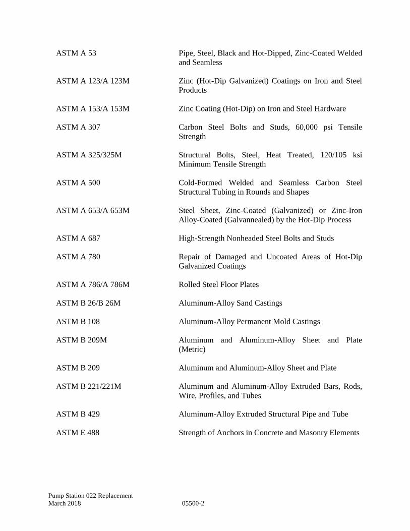
Pump Station 022 Replacement
March 2018 05500-2
ASTM A 53 Pipe, Steel, Black and Hot-Dipped, Zinc-Coated Welded
and Seamless
ASTM A 123/A 123M Zinc (Hot-Dip Galvanized) Coatings on Iron and Steel
Products
ASTM A 153/A 153M Zinc Coating (Hot-Dip) on Iron and Steel Hardware
ASTM A 307 Carbon Steel Bolts and Studs, 60,000 psi Tensile
Strength
ASTM A 325/325M Structural Bolts, Steel, Heat Treated, 120/105 ksi
Minimum Tensile Strength
ASTM A 500 Cold-Formed Welded and Seamless Carbon Steel
Structural Tubing in Rounds and Shapes
ASTM A 653/A 653M Steel Sheet, Zinc-Coated (Galvanized) or Zinc-Iron
Alloy-Coated (Galvannealed) by the Hot-Dip Process
ASTM A 687 High-Strength Nonheaded Steel Bolts and Studs
ASTM A 780 Repair of Damaged and Uncoated Areas of Hot-Dip
Galvanized Coatings
ASTM A 786/A 786M Rolled Steel Floor Plates
ASTM B 26/B 26M Aluminum-Alloy Sand Castings
ASTM B 108 Aluminum-Alloy Permanent Mold Castings
ASTM B 209M Aluminum and Aluminum-Alloy Sheet and Plate
(Metric)
ASTM B 209 Aluminum and Aluminum-Alloy Sheet and Plate
ASTM B 221/221M Aluminum and Aluminum-Alloy Extruded Bars, Rods,
Wire, Profiles, and Tubes
ASTM B 429 Aluminum-Alloy Extruded Structural Pipe and Tube
ASTM E 488 Strength of Anchors in Concrete and Masonry Elements
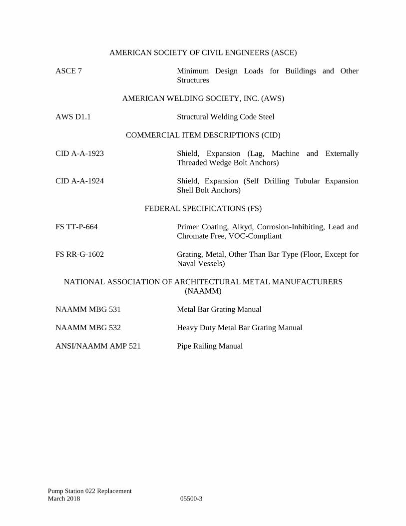
Pump Station 022 Replacement
March 2018 05500-3
AMERICAN SOCIETY OF CIVIL ENGINEERS (ASCE)
ASCE 7 Minimum Design Loads for Buildings and Other
Structures
AMERICAN WELDING SOCIETY, INC. (AWS)
AWS D1.1 Structural Welding Code Steel
COMMERCIAL ITEM DESCRIPTIONS (CID)
CID A-A-1923 Shield, Expansion (Lag, Machine and Externally
Threaded Wedge Bolt Anchors)
CID A-A-1924 Shield, Expansion (Self Drilling Tubular Expansion
Shell Bolt Anchors)
FEDERAL SPECIFICATIONS (FS)
FS TT-P-664 Primer Coating, Alkyd, Corrosion-Inhibiting, Lead and
Chromate Free, VOC-Compliant
FS RR-G-1602 Grating, Metal, Other Than Bar Type (Floor, Except for
Naval Vessels)
NATIONAL ASSOCIATION OF ARCHITECTURAL METAL MANUFACTURERS
(NAAMM)
NAAMM MBG 531 Metal Bar Grating Manual
NAAMM MBG 532 Heavy Duty Metal Bar Grating Manual
ANSI/NAAMM AMP 521 Pipe Railing Manual
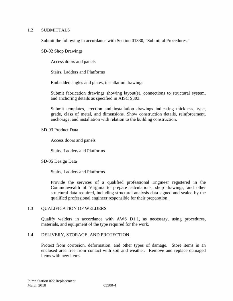
Pump Station 022 Replacement
March 2018 05500-4
1.2 SUBMITTALS
Submit the following in accordance with Section 01330, "Submittal Procedures."
SD-02 Shop Drawings
Access doors and panels
Stairs, Ladders and Platforms
Embedded angles and plates, installation drawings
Submit fabrication drawings showing layout(s), connections to structural system,
and anchoring details as specified in AISC S303.
Submit templates, erection and installation drawings indicating thickness, type,
grade, class of metal, and dimensions. Show construction details, reinforcement,
anchorage, and installation with relation to the building construction.
SD-03 Product Data
Access doors and panels
Stairs, Ladders and Platforms
SD-05 Design Data
Stairs, Ladders and Platforms
Provide the services of a qualified professional Engineer registered in the
Commonwealth of Virginia to prepare calculations, shop drawings, and other
structural data required, including structural analysis data signed and sealed by the
qualified professional engineer responsible for their preparation.
1.3 QUALIFICATION OF WELDERS
Qualify welders in accordance with AWS D1.1, as necessary, using procedures,
materials, and equipment of the type required for the work.
1.4 DELIVERY, STORAGE, AND PROTECTION
Protect from corrosion, deformation, and other types of damage. Store items in an
enclosed area free from contact with soil and weather. Remove and replace damaged
items with new items.
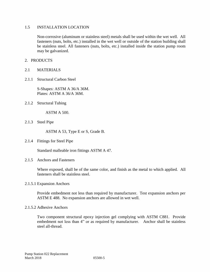
Pump Station 022 Replacement
March 2018 05500-5
1.5 INSTALLATION LOCATION
Non-corrosive (aluminum or stainless steel) metals shall be used within the wet well. All
fasteners (nuts, bolts, etc.) installed in the wet well or outside of the station building shall
be stainless steel. All fasteners (nuts, bolts, etc.) installed inside the station pump room
may be galvanized.
2. PRODUCTS
2.1 MATERIALS
2.1.1 Structural Carbon Steel
S-Shapes: ASTM A 36/A 36M.
Plates: ASTM A 36/A 36M.
2.1.2 Structural Tubing
ASTM A 500.
2.1.3 Steel Pipe
ASTM A 53, Type E or S, Grade B.
2.1.4 Fittings for Steel Pipe
Standard malleable iron fittings ASTM A 47.
2.1.5 Anchors and Fasteners
Where exposed, shall be of the same color, and finish as the metal to which applied. All
fasteners shall be stainless steel.
2.1.5.1 Expansion Anchors
Provide embedment not less than required by manufacturer. Test expansion anchors per
ASTM E 488. No expansion anchors are allowed in wet well.
2.1.5.2 Adhesive Anchors
Two component structural epoxy injection gel complying with ASTM C881. Provide
embedment not less than 4” or as required by manufacturer. Anchor shall be stainless
steel all-thread.
Pump Station 022 Replacement
March 2018 05500-6
2.1.5.3 Self-drilling concrete anchors
McMaster-Carr catalog No. 103, Item No. 97052A.
2.1.5.4 Lag Screws and Bolts
ANSI B18.2.1, type and grade best suited for the purpose.
2.1.5.5 Toggle Bolts
ANSI B18.2.1.
2.1.5.6 Bolts, Nuts, Studs and Rivets
ASME/ANSI B18.2.2 and ASTM A 687 or ASTM A 307, ASTM A 325.
2.1.5.7 Powder Driven Fasteners
Use when permitted by ANSI A10.3. Follow safety provisions of ANSI A10.3.
2.1.5.8 Screws
ANSI B18.2.1, ANSI B18.6.2, and ANSI B18.6.3.
2.1.5.9 Washers
Provide plain washers to conform to ASME/ANSI B18.22.1. Provide beveled washers
for American Standard beams and channels, square or rectangular, tapered in thickness,
and smooth. Provide lock washers to conform to ASME/ANSI B18.21.1.
2.1.6 Aluminum Alloy Products
Conform to ASTM B 209 for sheet plate, ASTM B 221 for extrusions and ASTM B
26/B 26M or ASTM B 108 for castings, as applicable. Provide aluminum extrusions at
least 1/8 inch thick and aluminum plate or sheet at least 0.050 inch thick.
Pump Station 022 Replacement
March 2018 05500-7
2.1.7 Ladders
Fabricate vertical ladders conforming to section 7 of 29 CER 1910.27. Use ¾-inch
aluminum rails for stringers and 1-inch diameter aluminum rods for rungs unless
otherwise shown on the drawings. Rungs to be as shown on drawings, but not less than
16 inches wide, spaced one foot apart, maximum, plug welded or shouldered and headed
to stringers. Install ladders so that distance from the center of the rungs to the finished
wall surface will not be less than 7 inches. Provide heavy clip angles, welded, riveted or
bolted to the stringer and drilled (for not less than two ½ inch diameter adhesive
anchors). Provide intermediate clip angles no more than every 48 inches on centers,
vertically. Coordinate clip angle locations with Precast Wet Well section joints so that
anchorage to precast well is 1 foot or more away from precast well joint so not to
compromise precast joint construction.
2.2 FABRICATION FINISHES
2.2.1 Galvanizing
Hot-dip galvanize items specified to be zinc-coated, after fabrication where practicable.
Galvanizing: ASTM A 123/A 123M, ASTM A 153/A 153Mor ASTM A 653/A 653M G-
90, as applicable. Galvanize anchor bolts, grating fasteners, washers, and parts or devices
necessary for proper installation, unless indicated otherwise.
2.2.2 Repair of Zinc-Coated Surfaces
Repair damaged surfaces with galvanizing repair method and paint conforming to ASTM
A 780.
2.2.3 Shop Cleaning and Painting
Provide steel with the manufacturer's standard prime coat for material to be field painted,
and manufacturer's standard coating for finished material.
2.2.4 Nonferrous Metal Surfaces
Protect by plating, anodic, or organic coatings.
2.2.5 Aluminum Surfaces
2.2.5.1 Surface Condition
Before finishes are applied, remove roll marks, scratches, rolled-in scratches, kinks,
stains, pits, orange peel, die marks, structural streaks, and other defects which will affect
uniform appearance of finished surfaces.
Pump Station 022 Replacement
March 2018 05500-8
2.2.5.2 Unexposed Sheet, Plate, and Extrusions
Unexposed sheet, plate and extrusions may have mill finish as fabricated. Sandblast
castings' finish, medium, AA 45, or AA 46.
2.3 ACCESS DOORS AND PANELS
2.3.1 Doors and Frames
Entry doors and frames shall comply with Section 08255, “Flush Doors and Frames.”
2.3.2 Louvers
Ventilation and exhaust louvered openings shall comply with Section 10201, “Metal Wall
Louvers.”
2.3.3 Embedded Access Doors
Provide flush type access doors where indicated for embedment in concrete. Fabricate
frames for embedded access doors using 1/4 inch thick one-piece, mill finish, extruded
aluminum frame, incorporating a continuous concrete anchor. Where the frame exterior
comes in contact with the concrete, provide a bituminous barrier coating. Doors shall be
constructed of 1/4 inch diamond plate aluminum with adequate reinforcing framing to
withstand a live load of 300 lbs per square foot. Door shall be double leaf and have
opening size as indicated. Door shall open 90 degrees and automatically lock with a
stainless steel hold open arm and aluminum handle. The hold open arm shall be assisted
by a fully enclosed stainless steel compression spring operator to act as a check in
retarding downward motion of the door and to assist in opening the door from below.
Door shall close flush with the frame and rest on a neoprene gasket. Hinges shall be
brass or stainless steel with stainless steel hardware. Doors shall be fitted with stainless
steel padlock hasps. Lock to be provided by locality. Frame drains shall be directed to
discharge away from the wet well and vault interiors. Embedded access doors shall be
warranted against defects in materials and workmanship for a period of no less than five
years. Acceptable manufacturers are Halliday Products Series 'HW' Access Doors, or
approved equal.
2.4 GUARD POSTS (BOLLARDS)
Provide 4 inch galvanized standard weight steel pipe as specified in ASTM A 53.
Anchor posts in concrete and fill solidly with concrete with minimum 28-day
compressive strength of 2500 psi. Posts shall be coated with paint in accordance with
Section 09900, Paints and Coatings. Color shall be Safety Yellow.
Pump Station 022 Replacement
March 2018 05500-9
2.5 MISCELLANEOUS PLATES AND SHAPES
Provide for items that do not form a part of the structural steel framework, such as lintels,
sill angles, miscellaneous mountings and frames. Provide lintels fabricated from
structural steel shapes over openings in masonry walls and partitions as indicated and as
required to support wall loads over openings. Provide with connections and fasteners.
Construct to have at least 200 mm 8 inches bearing on masonry at each end. Provide
angles and plates, ASTM A 36/A 36M, for embedment as indicated. Galvanize all
embedded items, whether exposed to the elements or not, according to ASTM A 123/A
123M. Piping supports within the wet well shall be aluminum or stainless steel securely
anchored to the wall with stainless steel fasteners.
3. EXECUTION
3.1 INSTALLATION
Install items at locations indicated and according to shop drawings.
3.2 ANCHORAGE, FASTENINGS, AND CONNECTIONS
Provide anchorage where necessary for fastening miscellaneous metal items securely in
place. Include for anchorage not otherwise specified or indicated slotted inserts,
expansion shields, and powder-driven fasteners, when approved for concrete; toggle bolts
and through bolts for masonry; machine and carriage bolts for steel; through bolts, lag
bolts, and screws for wood. Do not use wood plugs in any material. Provide non-ferrous
attachments for non-ferrous metal. Make exposed fastenings of compatible materials,
generally matching in color and finish, to which fastenings are applied. Fasteners used in
the wet well shall be stainless steel. Conceal fastenings where practicable.
3.3 BUILT-IN-WORK
Form for anchorage of metal work built-in with concrete or masonry, or provide with
suitable anchoring devices as indicated or as required. Furnish metal work in ample time
for securing in place as the work progresses. Fabrications shall be installed and protected
in accordance with manufacturer's recommendations.
3.4 WELDING
Perform welding, welding inspection, and corrective welding, in accordance with AWS
D1.1. Use continuous welds on all exposed connections. Grind visible welds smooth in
the finished installation

Pump Station 022 Replacement
March 2018 05500-10
3.5 FIELD FINISHING
3.5.1 Coatings
Coat exposed metal items in accordance with Section 09900, “Paints and Coatings.”
Aluminum items shall be anodized finish and not coated except where specified herein.
3.5.2 Dissimilar Materials
Where dissimilar metals are in contact, or where aluminum is in contact with concrete,
mortar, masonry, wood, or absorptive materials subject to wetting, protect surfaces with a
coat conforming to FS TT-P-664 to prevent galvanic or corrosive action. Alkyd is not to
be used on metal in contact with concrete or masonry.
3.5.3 Field Preparation
Remove rust preventive coating just prior to field erection, using a remover approved by
the rust preventive manufacturer. Surfaces, when assembled, shall be free of rust, grease,
dirt and other foreign matter. Do not clean or paint surface when damp or exposed to
foggy or rainy weather, when metallic surface temperature is less than 5 degrees F above
the dew point of the surrounding air, or when surface temperature is below 45 degrees F
or over 95 degrees F, unless approved by the Engineer.
END OF SECTION
Pump Station 022 Replacement
March 2018 08255-1
SECTION 08255 –DOORS AND FRAMES
1 GENERAL
1.1 REFERENCES
The publications listed below form a part of this specification to the extent referenced.
The publications are referred to in the text by the basic designation only. The referenced
publications shall be the current effective edition.
AMERICAN SOCIETY FOR TESTING AND MATERIALS (ASTM)
A. AAMA 1503-98 - Thermal Transmittance and Condensation Resistance of
Windows, Doors and Glazed Wall Sections.
B. ANSI A250.4 - Test Procedure and Acceptance Criteria for Physical Endurance
for Steel Doors and Hardware Reinforcings.
C. ASTM B 117 - Operating Salt Spray (Fog) Apparatus.
D. ASTM B 209 - Aluminum and Aluminum-Alloy Sheet and Plate.
E. ASTM B 221 - Aluminum-Alloy Extruded Bars, Rods, Wire, Profiles, and Tubes.
F. ASTM D 256 - Determining the Pendulum Impact Resistance of Notched
Specimens of Plastics.
G. ASTM D 543 - Evaluating the Resistance of Plastics to Chemical Reagents.
H. ASTM D 570 - Water Absorption of Plastics.
I. ASTM D 638 - Tensile Properties of Plastics.
J. ASTM D 790 - Flexural Properties of Unreinforced and Reinforced Plastics and
Electrical Insulating Materials.
K. ASTM D 1308 - Effect of Household Chemicals on Clear and Pigmented Organic
Finishes.
L. ASTM D 1621 - Compressive Properties of Rigid Cellular Plastics.
M. ASTM D 1623 - Tensile and Tensile Adhesion Properties of Rigid Cellular
Plastics.
Pump Station 022 Replacement
March 2018 08255-2
N. ASTM D 2126 - Response of Rigid Cellular Plastics to Thermal and Humid
Aging.
O. ASTM D 2583 - Indentation Hardness of Rigid Plastics by Means of a Barcol
Impressor.
P. ASTM D 5420 – Impact Resistance of Flat Rigid Plastic Specimens by Means of
a Falling Weight.
Q. ASTM D 6670-01 - Standard Practice for Full-Scale Chamber Determination of
Volatile Organic Emissions from Indoor Materials/Products.
R. ASTM E 84 - Surface Burning Characteristics of Building Materials.
S. ASTM E 90 - Laboratory Measurement of Airborne Sound Transmission Loss of
Building Partitions.
T. ASTM E 283 - Determining the Rate of Air Leakage Through Exterior Windows,
Curtain Walls, and Doors Under Specified Pressure Differences Across the
Specimen.
U. ASTM E 330 - Structural Performance of Exterior Windows, Curtain Walls, and
Doors by Uniform Static Air Pressure Difference.
V. ASTM E 331 - Water Penetration of Exterior Windows, Skylights, Doors, and
Curtain Walls by Uniform Static Air Pressure Difference.
W. ASTM F 476 - Security of Swinging Door Assemblies.
X. ASTM F 1642-04 – Standard Test Method for Glazing Systems Subject to Air
Blast Loading.
Y. NWWDA T.M. 7-90 – Cycle Slam Test Method
Z. SFBC PA 201 - Impact Test Procedures.
AA. SFBC PA 203 - Criteria for Testing Products Subject to Cyclic Wind Pressure
Loading.
AB. SFBC 3603.2 (b)(5) - Forced Entry Resistance Test.
Pump Station 022 Replacement
March 2018 08255-3
1.2 SUBMITTALS
Submit the following in accordance with Section 01330, "Submittal Procedures."
SD-02 Shop Drawings
Doors
Frames
Accessories
Weatherstripping
Show elevations, construction details, metal gages, hardware provisions, method of
glazing, and installation details.
Submit door and frame locations.
SD-03 Product Data
Doors
Frames
Accessories
Weatherstripping
Submit manufacturer's descriptive literature for doors, frames, and accessories.
Include data and details on door construction, panel (internal) reinforcement,
insulation, and door edge construction.
SD-04 Samples
Factory-applied finish. Where colors are not indicated, submit manufacturer's
standard colors and patterns for selection.
Pump Station 022 Replacement
March 2018 08255-4
1.3 DELIVERY, STORAGE, AND HANDLING
Deliver doors, frames, and accessories undamaged and with protective wrappings or
packaging. Strap knock-down frames in bundles. Store doors and frames on platforms
under cover in clean, dry, ventilated, and accessible locations, with 1/4 inch airspace
between doors. Remove damp or wet packaging immediately and wipe affected surfaces
dry. Replace damaged materials with new.
2 PRODUCTS
2.1 FLUSH DOORS AND FRAMES
CP3 FRP Door and Frame FRP Division Chase Industries (See www.chem-pruf.com), or
approved equal.
Door Dimensions:
4’ – 0” x 7’ – 0”
2.1.1 FRP Doors
Doors shall be made of fiberglass reinforced plastic (FRP) using Class 1 premium resin
with no fillers that is specifically tailored to resist chemicals and contaminants typically
found in environment for which these specifications are written.
Doors shall be of flush construction, having no seams or cracks. Doors and frames shall
maintain the same physical properties throughout the structure,
2.1.2 Anchors
Provide anchors to secure the frame to adjoining construction. Provide steel anchors,
zinc-coated or painted with rust-inhibitive paint, not lighter than 18 gage.
2.1.2.1 Wall Anchors
Provide at least three anchors for each jamb. For frames which are more than 7.5 feet in
height, provide one additional anchor for each jamb for each additional 2.5 feet or
fraction thereof.
A. Masonry: Provide anchors of corrugated or perforated steel straps or 3/16 inch
diameter steel wire, adjustable or T-shaped;
B. Completed openings: Secure frames to previously placed concrete or masonry with
expansion bolts in accordance with SDI 111F.
2.1.2.2 Floor Anchors
Provide floor anchors drilled for 3/8 inch anchor bolts at bottom of each jamb member.
Pump Station 022 Replacement
March 2018 08255-5
2.2 WEATHERSTRIPPING
As specified in Section 08710, "Door Hardware."
2.3 HARDWARE PREPARATION
All related hardware as specified must be furnished and installed by the door frame
manufacturer to maintain product quality, function and warranty as well as to ensure
sufficient support/reinforcement.
2.4 FABRICATION AND WORKMANSHIP
Finished doors and frames shall be strong and rigid, neat in appearance, and free from
defects, waves, scratches, cuts, dents, ridges, holes, warp, and buckle. Molded members
shall be clean cut, straight, and true, with joints coped or mitered, well formed, and in
true alignment. Dress exposed welded and soldered joints smooth. Design door frame
sections for use with the wall construction indicated. Corner joints shall be well formed
and in true alignment. Conceal fastenings where practicable. On wraparound frames for
masonry partitions, provide a throat opening 1/8 inch larger than the actual masonry
thickness. Design frames in exposed masonry walls or partitions to allow sufficient space
between the inside back of trim and masonry to receive calking compound.
2.4.1 Grouted Frames
For frames to be installed in exterior walls and to be filled with mortar or grout, fill the
stops with strips of rigid insulation to keep the grout out of the stops and to facilitate
installation of stop-applied head and jamb seals.
2.4.2 Finish
Doors and frames shall have a Resin-rich gelcoat of the specified color integrally molded
in at time of manufacture resulting in a smooth gloss surface that is dense and non-
porous. To achieve optimum surface characteristics, the gelcoat shall be cured within a
temperature range of 120F to 170F creating an impermeable outer surface, uniform
bronze color throughout, and a permanent homogeneous bond with the resin/fiberglass
substrate beneath.
2.5 WARRANTY
All fiberglass doors and frames shall have a lifetime guarantee against failure due to
corrosion. Additionally, fiberglass doors and fiberglass frames shall be guaranteed for a
minimum of ten years against failure due to materials and workmanship, including warp,
Separation or delamination, and expansion of the core

Pump Station 022 Replacement
March 2018 08255-6
3 EXECUTION
3.1 INSTALLATION
3.1.1 Frames
Set frames in accordance with manufacturer’s instructions. Plumb, align, and brace
securely until permanent anchors are set. Anchor bottoms of frames with expansion bolts
or powder-actuated fasteners. Build in or secure wall anchors to adjoining construction.
Backfill frames with mortar. When an additive is provided in the mortar, coat inside of
frames with corrosion-inhibiting bituminous material. For frames in exterior walls,
ensure that stops are filled with rigid insulation before grout is placed.
Note: Contractor has option to have precast building manufacturer fabricate building
wall with door frame installed during wall fabrication provided that the FRP door and
frame meet the requirements stated in this specification. Door frame width shall be
coordinated with precast building wall thickness. Frame may be either butted, cast in or
wrapped.
3.1.2 Doors
A. Doors shall be delivered at job site individually crated. Each crate to be clearly
marked with the specific opening information for quick and easy identification.
B. All single doors to be shipped completely assembled in the frame with hardware
installed. Double doors to be prehung at the factory to ensure a proper fit and that
hardware functions properly, then disassembled for shipping purposes.
C. Install door opening assemblies in accordance with shop drawings and manufacturer’s
printed installation instructions, using installation methods and materials specified in
installation instructions.
D. Field alteration of doors or frames to accommodate field conditions is strictly
prohibited.
E. Site tolerances: Maintain plumb and level tolerance specified in manufacturer’s
printed installation instructions
F. After erection and glazing, clean and adjust hardware.
G. Optional: Contractor has option to have precast building manufacturer fabricate
building with door installed during wall fabrication provided that the FRP door and
frame meet the requirements stated in this specification. Door frame width shall be
coordinated with precast building wall thickness. Frame may be either butted, cast in
or wrapped.
3.2 PROTECTION
Protect doors and frames from damage. Repair damaged doors and frames prior to
completion and acceptance of the project or replace with new, as directed.
Pump Station 022 Replacement
March 2018 08255-7
3.3 CLEANING
Upon completion, clean exposed surfaces of doors and frames thoroughly. Remove
mastic smears and other unsightly marks.
END OF SECTION

Pump Station 022 Replacement
March 2018 08255-8
This Page Intentionally Left Blank
Pump Station 022 Replacement
March 2018 08710-1
SECTION 08710 - DOOR HARDWARE
1. GENERAL
1.1 REFERENCES
The publications listed below form a part of this specification to the extent referenced.
The publications are referred to in the text by the basic designation only. The referenced
publications shall be the current effective edition.
AMERICAN SOCIETY FOR TESTING AND MATERIALS (ASTM)
ASTM E 283 Rate of Air Leakage Through Exterior Windows,
Curtain Walls, and Doors Under Specified Pressure
Differences Across the Specimen
ASTM F 883 Padlocks
BUILDERS HARDWARE MANUFACTURERS ASSOCIATION, INC. (BHMA)
ANSI/BHMA A156.1 Butts and Hinges (BHMA 101)
ANSI/BHMA A156.2 Bored and Preassembled Locks and Latches (BHMA
601)
ANSI/BHMA A156.3 Exit Devices (BHMA 701)
ANSI/BHMA A156.4 Door Controls - Closers (BHMA 301)
ANSI/BHMA A156.5 Auxiliary Locks & Associated Products (BHMA 501)
ANSI/BHMA A156.6 Architectural Door Trim (BHMA 1001)
ANSI/BHMA A156.7 Template Hinge Dimensions
ANSI/BHMA A156.8 Door Controls - Overhead Holders (BHMA 311)
ANSI/BHMA A156.12 Interconnected Locks & Latches (BHMA 611)
ANSI/BHMA A156.13 Mortise Locks & Latches (BHMA 621)
ANSI/BHMA A156.15 Closer Holder Release Devices
ANSI/BHMA A156.16 Auxiliary Hardware
ANSI/BHMA A156.17 Self Closing Hinges & Pivots
Pump Station 022 Replacement
March 2018 08710-2
ANSI/BHMA A156.18 Materials and Finishes (BHMA 1301)
UNDERWRITERS LABORATORIES INC. (UL)
UL BMD Building Materials Directory
1.2 SUBMITTALS
Submit the following in accordance with Section 01330, "Submittal Procedures."
SD-03 Product Data
Hardware items
SD-08 Manufacturer's Instructions
Installation
SD-10 Operation and Maintenance Data
Hardware Schedule items, Data Package 1S
Submit data package in accordance with Section 01781, "Operation and
Maintenance Data."
1.3 QUALITY ASSURANCE
1.3.1 Hardware Manufacturers and Modifications
Provide, as far as feasible, locks, hinges, and closers of one lock, hinge, or closer
manufacturer's make. Modify hardware as necessary to provide features indicated or
specified.
1.4 DELIVERY, STORAGE, AND HANDLING
Deliver hardware in original individual containers, complete with necessary
appurtenances including fasteners and instructions. Deliver keys to the Owner directly.
Pump Station 022 Replacement
March 2018 08710-3
2. PRODUCTS
2.1 TEMPLATE HARDWARE
Hardware to be applied to prefinished doors shall be made to template. Promptly furnish
template information or templates to door and frame manufacturers. Template hinges
shall conform to ANSI/BHMA A156.7. Coordinate hardware items to prevent
interference with other hardware.
2.2 HARDWARE SETS
Provide hardware sets for each door in the following quantity, item, manufacturer and
product designation, size, and finish or color, as applicable.
3 Full Mortise Hinges Stanley # FBB191, 4 1/2 x 4 1/2 inch, US 32D
1 Lockset/Latch: Best 40H-Series with 14J lever design, US 32D,
N-Passage type (Cannot be locked).
1 Hasp Stainless Steel, US 32D
1 Overhead Holder-Stop Glynn-Johnson, 81 series, US 32D
1 Kick plate as specified, US 32D
1 Threshold NGP # 425 Saddle Type 1/2 x 5 inch
3 Silencers Glenn-Johnson #GJ64 (Grey)
1 Set Jamb and Head Seals Reese 797, Self Adhesive
36" Door Sweep Reese 967 DUR
2.3 HARDWARE ITEMS
Hinges, pivots, locks, latches, exit devices, bolts, and closers shall be clearly and
permanently marked with the manufacturer's name or trademark where it will be visible
after the item is installed. For closers with covers, the name or trademark may be beneath
the cover.
2.3.1 Hinges
Five knuckle, full mortise, ANSI/BHMA A156.1, 4 1/2 by 4 1/2 inches unless otherwise
specified. Provide three hinges per door leaf to 90 inches high and one additional hinge
for each 30 inches of additional height. Full mortise hinges shall be stainless steel at
doors opening to exterior and interior, finish shall match lockset. Provide wide throw,
full mortise hinges for doors requiring 180 degree swing. Construct loose pin hinges for
exterior doors and reverse-bevel interior doors so that pins will be nonremovable,
nonrising when door is closed. Other antifriction bearing hinges may be provided in lieu
of ball-bearing hinges. Tips shall be Flat button with matching plug, finished to match
leaves, except where hospital tips are indicated.
Pump Station 022 Replacement
March 2018 08710-4
2.3.2 Thresholds
ANSI A 156.21, aluminum. One-piece units with bolt cutouts, not more than 1/2 inch
high.
2.3.3 Locks and Latches
ANSI/BHMA A156.2, Grade 1.
2.3.3.1 Mortise Locks and Latches
ANSI/BHMA A156.13. Provide heavy-duty, field reversible, all working parts forged or
machined, mortise locks. Cut escutcheons to suit cylinders and provide trim items with
straight, beveled, or smoothly rounded sides, corners, and edges. Knobs and roses of
mortise locks shall have screwless shanks and no exposed screws. Provide 3/4 inch
minimum throw of latch for mortise locks. Lock shall have a 2 3/4 inch backset.
2.3.4 Lock Trim
Cast, forged, or heavy wrought construction and commercial plain design with curved lip
extended to protect frame. Finish to match hardware set.
2.3.4.1 Lever Handles
Provide lever handles in lieu of knobs. Lever handles for exit devices shall meet the test
requirements of ANSI/BHMA A156.13 for mortise locks. Lever handle locks shall have
a breakaway feature (such as a weakened spindle or a shear key) to prevent irreparable
damage to the lock when a force in excess of that specified in ANSI/BHMA A156.13 is
applied to the lever handle. Lever handles shall return to within 1/2 inch of the door face.
2.3.5 Closers
ANSI/BHMA A156.4, Grade 1. Provide with brackets, arms, mounting devices,
fasteners, and other features necessary for the particular application. Size closers in
accordance with manufacturer's recommendations. Provide manufacturer's 10 year
warranty. Provide with integral back checks and cold weather fluid.
2.3.6 Overhead Holders
ANSI/BHMA A156.8. Adjustable, surface mounted, including hold-open feature for
exterior and interior installations.
2.3.7 Closer Holder-Release Devices
ANSI/BHMA A156.15.
Pump Station 022 Replacement
March 2018 08710-5
2.3.8 Door Protection Plates
ANSI/BHMA A156.6. Stainless steel, 0.050 inch thickness. Apply to push side of doors
equipped with closers. Width for single doors shall be 2 inches less than door width;
width for pairs of doors shall be one inch less than door width. Height of kick plates
shall be 12 inches.
2.3.9 Door Stops and Silencers
ANSI/BHMA A156.16. Provide three silencers for each single door, two for each pair.
2.3.10 Weather Stripping
A set shall include head and jamb seals, drop seals and sweep strips. Sweeps shall be
extruded aluminum retainer with a flexible sweep of flexible vinyl or neoprene wiper or a
sweep seal strip. Aluminum shall be anodized.
2.3.11 Special Tools
Provide special tools, such as spanner and socket wrenches and dogging keys, required to
service and adjust hardware items.
2.4 FASTENERS
Provide fasteners of proper type, quality, size, quantity, and finish with hardware.
Fasteners exposed to weather shall be of nonferrous metal or stainless steel. Provide
fasteners of type necessary to accomplish a permanent installation.
2.5 FINISHES
US32D for stainless steel. Aluminum finishes shall be clear anodized.
3. EXECUTION
3.1 INSTALLATION
Install hardware in accordance with manufacturers' printed instructions. Provide machine
screws set in expansion shields for fastening hardware to solid concrete and masonry
surfaces. Provide toggle bolts where required for fastening to hollow core construction.
Provide through bolts where necessary for satisfactory installation.
3.1.1 Weather Stripping Installation
Handle and install weather stripping so as to prevent damage. Provide full contact,
weather-tight seals. Doors shall operate without binding.
Pump Station 022 Replacement
March 2018 08710-6
3.2 HARDWARE LOCATIONS
ANSI/SDI 100 or door manufacturer's recommended locations and as follows, unless
indicated or specified otherwise:
A. Door Knobs/Levers: 3 feet – 2 inches above finished floor to center of knob/lever
unless otherwise directed by the Engineer.
B. Kick and Armor Plates: Push side of single-acting doors. Both sides of double-
acting doors.
C. Locking Hasp: 4 feet – 0 inches above finished floor to center of hasp on exterior of
door unless otherwise directed by the Engineer.
3.3 FIELD QUALITY CONTROL
After installation, protect hardware from paint, stains, blemishes, and other damage until
acceptance of work. Submit notice of testing 15 days before scheduled, so that testing
can be witnessed by the Engineer and the locality. Adjust hinges, locks, latches, bolts,
holders, closers, and other items to operate properly. Correct, repair, and finish, as
directed, errors in cutting and fitting and damage to adjoining work.
END OF SECTION
Pump Station 022 Replacement
March 2018 09900-1
SECTION 09900 - PAINTS AND COATINGS
1. GENERAL
1.1 REFERENCES
The publications listed below form a part of this specification to the extent referenced.
The publications are referred to in the text by the basic designation only. The referenced
publications shall be the current effective edition.
AMERICAN CONFERENCE OF GOVERNMENTAL INDUSTRIAL HYGIENISTS (ACGIH)
ACGIH TLV-BKLT Threshold Limit Values (TLVs) for Chemical
Substances and Physical Agents and Biological
Exposure Indices (BEIs)
ACGIH TLV-DOC Documentation of Threshold Limit Values and
Biological Exposure Indices
AMERICAN SOCIETY FOR TESTING AND MATERIALS (ASTM)
ASTM D 6386 Preparation of Zinc (Hot-Dip Galvanized) Coated Iron
and Steel Product and Hardware Surfaces for Painting
CODE OF FEDERAL REGULATIONS (CFR)
29 CFR 1910.1000 Air Contaminants
COMMERCIAL ITEM DESCRIPTIONS (CID)
CID A-A-378 Putty, Linseed Oil Type (For Wood Sash Glazing)
CID A-A-1558 Paint, Stencil
CID A-A-2904 Thinner, Paint, Mineral Spirits, Regular and Odorless
CID A-A-50557 Primer, Water-Borne, Acrylic or Modified Acrylic, For
Metal Surfaces
FEDERAL STANDARDS (FED-STD)
FED-STD-313 Material Safety Data, Transportation Data and Disposal
Data for Hazardous Materials Furnished to Government
Activities
Pump Station 022 Replacement
March 2018 09900-2
STEEL STRUCTURES PAINTING COUNCIL (SSPC)
SSPC PA 1 Shop, Field, and Maintenance Painting
SSPC PA 3 Safety in Paint Application
SSPC SP 1 Solvent Cleaning
SSPC SP 3 Power Tool Cleaning
SSPC SP 6 Commercial Blast Cleaning
SSPC SP 7 Brush-Off Blast Cleaning
SSPC SP 10 Near-White Blast Cleaning
1.2 SUBMITTALS
Submit the following in accordance with Section 01330, "Submittal Procedures."
SD-03 Product Data
Coating
Sealant
For each type of coating, sealant, or other product furnished, submit data from the
manufacturer's paint laboratory indicating that the product conforms to requirements
of the referenced specification.
SD-04 Samples
Color
Submit manufacturer's samples of paint colors. Cross reference color samples to
color scheme as indicated.
SD-08 Manufacturer's Instructions
Application instructions
Manufacturer's material safety data sheets
Submit Manufacturer's material safety data sheets for coatings, solvents, and other
potentially hazardous materials, as defined in FED-STD-313.
Pump Station 022 Replacement
March 2018 09900-3
SD-07 Certificates
Wet Well Coating
Provide written certification from a certified manufacturer's representative that the
surfaces of the wet well were prepared in the proper manner for installation of the
coating product and the product was prepared and installed in accordance with the
manufacturer's recommendations. This certification shall be performed on-site at
the Contractor's expense. Manufacturer's certification shall consist of evaluating the
surface preparation, the coating product during the preparation stage and upon
completion of its application in accordance with manufacturer's testing standards.
SD-11 Closeout Submittals
Wet Well Coatings Warranty
The Contractor shall warrant the wet well coatings to be free of defects in
workmanship and/or materials for a period of five (5) years from the date of final
acceptance. Final acceptance will be based on field inspection by the Locality and
the Engineer. The Contractor shall, within a reasonable time after receipt of written
notice thereof, repair defects in materials and/or workmanship which may develop
during the aforementioned time period, and any damage to other work caused by
such defects or the repairing of same, at his own expense and without cost to the
Owner.
1.3 REGULATORY REQUIREMENTS
1.3.1 Lead Content
Do not use coatings having a lead content over 0.06 percent by weight of nonvolatile
content.
1.3.2 Chromate Content
Do not use coatings containing zinc-chromate or strontium-chromate.
1.3.3 Asbestos Content
Materials shall not contain asbestos.
1.3.4 Mercury Content
Materials shall not contain mercury or mercury compounds.

Pump Station 022 Replacement
March 2018 09900-4
1.3.5 Silica Sand
The use of silica sand is prohibited.
1.3.6 Human Carcinogens
Materials shall not contain ACGIH TLV-BKLT and ACGIH TLV-DOC confirmed
human carcinogens (A1) or suspected human carcinogens (A2).
1.4 PACKAGING, LABELING, AND STORAGE
Paints shall be in sealed containers that legibly show the designation name, formula or
specification number, batch number, color, quantity, date of manufacture, manufacturer's
formulation number, manufacturer's directions including any warnings and special
precautions, and name and address of manufacturer. Pigmented paints shall be furnished
in containers not larger than 5 gallons. Paints and thinners shall be stored in accordance
with the manufacturer's written directions, and as a minimum, stored off the ground,
under cover, with sufficient ventilation to prevent the buildup of flammable vapors, and
at temperatures between 40 to 95 degrees F. Protect from freezing or damage.
1.5 SAFETY METHODS
Apply coating materials using safety methods and equipment in accordance with the
following:
1.5.1 Safety Methods Used During Coating Application
Comply with the requirements of SSPC PA 3.
1.5.2 Toxic Materials
To protect personnel from overexposure to toxic materials, conform to the most stringent
guidance of:
A. The chemical manufacturer when using mineral spirits, or other chemicals. Use
impermeable gloves, chemical goggles or face shield, and other recommended
protective clothing and equipment to avoid exposure of skin, eyes, and respiratory
system. Conduct work in a manner to minimize exposure of building occupants and
the general public.
B. 29 CFR 1910.1000.
C. ACGIH TLV-BKLT, threshold limit values.
D. Manufacturer's material safety data sheets (MSDS).

Pump Station 022 Replacement
March 2018 09900-5
1.6 ENVIRONMENTAL CONDITIONS
The contractor shall be responsible for taking wet bulb, dry bulb, surface temperature,
humidity and dew point readings to ensure that conditions are within the manufacturer's
specifications prior to any painting. A daily weather conditions log shall be maintained
during all paint applications of the above parameters and shall be submitted to the
Engineer for review upon request.
1.6.1 Exterior Coatings
Not applicable.
1.6.2 Interior Coatings
Apply coatings when surfaces to be painted are dry and the following surface
temperatures can be maintained:
A. Between 50 and 95 degrees F during application of enamels and varnishes;
B. Between 50 and 95 degrees F during application of other coatings.
1.7 COLOR SELECTION
Colors of finish coats shall be as indicated or specified. Where not indicated or specified,
colors shall be selected by the Owner. Manufacturers' names and color identification are
used for the purpose of color identification only. Named products are acceptable for use
only if they conform to specified requirements. Products of other manufacturers are
acceptable if the colors approximate colors indicated and the product conforms to
specified requirements.
1.8 LOCATION AND SURFACE TYPE TO BE PAINTED
1.8.1 Painting Included
Where a space or surface is indicated to be painted, include the following unless
indicated otherwise.
A. Surfaces behind portable objects and surface mounted articles readily detachable by
removal of fasteners, such as screws and bolts.
B. New factory finished surfaces that require identification or color coding and factory
finished surfaces that are damaged during performance of the work.
C. Existing coated surfaces that are damaged during performance of the work.
Pump Station 022 Replacement
March 2018 09900-6
D. All exterior wood, ferrous and galvanized metal surfaces, and all interior surfaces
unless indicated not to be painted. Surfaces included to be painted, but not
necessarily limited to, are:
1. Interior concrete wall and ceiling surfaces.
2. Interior CMU wall surfaces.
3. Plywood and gypsum board ceilings.
4. Equipment supports.
5. Steel beams and framing.
6. Metal fabrications, bollards, hoist beams, and lintels.
7. Plain, insulated, or wrapped interior building piping, valves, fittings and
appurtenances.
8. Plain, insulated or wrapped exterior building piping, valves, fittings,
hydrants, appurtenances above ground and inside tankage (including within
the wet well).
9. Plain, insulated or wrapped interior ductwork and appurtenances only when
located in areas indicated to be painted.
10. Plain, insulated or wrapped exterior ductwork and appurtenances where
indicated to be painted.
11. Interior pipe, conduit and appurtenances when located in areas indicated to
be painted.
12. Exterior pipe, conduit and appurtenances above ground.
13. Ferrous and galvanized metal conduits.
14. Exposed woodwork.
15. Machinery and equipment, including factory finished, electrical panels,
switchboards, switch gear, safety switches, motor starter equipment,
busways, raceways, high-voltage conduits, and any ferrous metal enclosure
not provided with an approved, weather and corrosion resistant finish
(excluding electrical bus conductors) or surfaces which have rusted.
Pump Station 022 Replacement
March 2018 09900-7
1.8.2 Painting Excluded
Do not paint the following unless indicated otherwise.
A. Surfaces concealed and made inaccessible by panelboards, fixed ductwork,
machinery, and equipment fixed in place.
B. Surfaces in concealed spaces. Concealed spaces are defined as enclosed spaces
above suspended ceilings, furred spaces, attic spaces, crawl spaces, and chases.
C. Steel to be embedded in concrete.
D. Copper, stainless steel, brass, and lead except existing coated surfaces.
E. Exposed to view aluminum surfaces including immersed surfaces except those
specified previously.
F. Fiberglass surfaces, unless indicated otherwise.
G. Interior of pipe, ductwork and conduits.
H. Moving parts of mechanical and electrical units.
I. Code labels and equipment identification and rating plates.
J. Factory furnished motor control centers, control panels, engines, engine generators,
outdoor electrical panels, and electrical switchgear.
K. Exterior surfaces of all louvers and fans.
1.8.3 Interior Painting
Includes new surfaces, existing uncoated surfaces, and existing coated surfaces of the
building and appurtenances as indicated and existing coated surfaces made bare by
cleaning operations. Where a space or surface is indicated to be painted, include the
following items, unless indicated otherwise.
A. Exposed columns, girders, beams, joists, and metal deck; and
B. Other contiguous surfaces.
1.8.4 Mechanical and Electrical Painting
Includes field coating of interior and exterior new and existing surfaces. Where a space
or surface is indicated to be painted, include the following items unless indicated
otherwise.
Pump Station 022 Replacement
March 2018 09900-8
A. Exposed piping, conduit, and ductwork;
B. Supports, hangers, air grilles, and registers;
C. Miscellaneous metalwork and insulation coverings.
2. PRODUCTS
2.1 MATERIALS
Conform to the coating specifications and standards referenced or as specified herein.
2.2 EXTERIOR BELOW-GRADE WALLS
Exterior below-grade walls shall be coated with Cooper Black No 733 rubberized
protective coating as manufactured by Cooper’s Creek Chemical Corporation or
approved equal. Coating shall be inspected by Engineer and Locality personnel prior to
placing backfill.
2.3 INTERIOR WET WELL
None.
2.4 IDENTIFICATION PLAQUE
Station identification plaque shall be mounted on station interior wall. Plaque shall be
black with minimum ¼” white engraved letters. Plaque shall include the following:
A. Station Name
B. Station Serial Number (from pump manufacturer)
C. Voltage
D. Horsepower
E. Design Flow (in gpm)
F. Design Total Dynamic Head (in feet)
3. EXECUTION
3.1 PROTECTION OF AREAS AND SPACES
Prior to surface preparation and coating applications, remove, mask, or otherwise protect,
hardware, hardware accessories, machined surfaces, radiator covers, plates, lighting
fixtures, public and private property, and other such items not to be coated that are in
contact with surfaces to be coated. Following completion of painting, workmen skilled in
the trades involved shall reinstall removed items. Restore surfaces contaminated by
coating materials, to original condition and repair damaged items.
Pump Station 022 Replacement
March 2018 09900-9
3.2 SURFACE PREPARATION
Remove dirt, splinters, loose particles, grease, oil, disintegrated coatings, and other
substances deleterious to coating performance as specified for each substrate.
3.2.1 Existing Coated Surfaces with No Defects
Before application of coatings, perform the following on surfaces covered by soundly-
adhered coatings, defined as those which cannot be removed with a putty knife:
A. Wipe previously painted surfaces to receive solvent-based coatings, except stucco
and similarly rough surfaces clean with a clean, dry cloth saturated with mineral
spirits, CID A-A-2904. Allow surface to dry. Wiping shall immediately precede
the application of the first coat of any coating, unless specified otherwise.
B. Sand existing enamel and other glossy surfaces to remove gloss. Brush and wipe
clean with a dry cloth.
C. The requirements specified are minimum. Comply also with the application
instructions of the paint manufacturer.
3.2.2 Existing Coated Surfaces with Minor Defects
Sand, spackle, and treat minor defects to render them smooth. Minor defects are defined
as scratches, nicks, cracks, gouges, spalls, alligatoring, chalking, and irregularities due to
partial peeling of previous coatings.
3.3 PREPARATION OF METAL SURFACES
3.3.1 Existing and New Ferrous Surfaces
Shop-coated Surfaces and Areas That Contain Rust, Mill Scale and Other Foreign
Substances: Solvent clean in accordance with SSPC SP 1 to remove oil and grease.
Where shop coat is missing or damaged, clean according to SSPC SP 3, SSPC SP 6, or
SSPC SP 10 as applicable for the surface use.
3.3.2 Galvanized Surfaces
A. New or Existing Galvanized Surfaces with Only Dirt and Zinc Oxidation Products:
Clean with solvent, steam, or non-alkaline detergent solution in accordance with
SSPC SP 1. If the galvanized metal has been passivated or stabilized, the coating
shall be completely removed by brush-off abrasive blast or other treatment, or the
surface shall be primed with a primer which is specifically recommended by the
paint manufacturer for use on passivated or stabilized galvanized steel. For new
galvanized steel to be coated, if absence of hexavalent stain inhibitors is not
documented, test as described in ASTM D 6386, and remove by one of the methods
described therein.
Pump Station 022 Replacement
March 2018 09900-10
B. Galvanized with Slight Coating Deterioration or with Little or No Rusting: Water
jetting to SSPC SP 12 WJ3 to remove loose coating from surfaces with less than 20
percent coating deterioration and no blistering, peeling, or cracking. Use inhibitor
as recommended by the coating manufacturer to prevent rusting.
C. Galvanized with Severe Deteriorated Coating or Severe Rusting: Spot abrasive blast
rusted areas as described for steel in SSPC SP 6, and abrasive blast as described for
steel in SSPC SP 7, to remove existing coating.
3.3.3 Aluminum, Other Non-Galvanized, and Non-Ferrous Surfaces
Surface Cleaning: Solvent clean in accordance with SSPC SP 1 and wash with mild non-
alkaline detergent to remove dirt and water soluble contaminates.
3.3.4 Terne-Coated Metal Surfaces
Solvent clean surfaces with mineral spirits, CID A-A-2904. Wipe dry with clean, dry
cloths.
3.3.5 Existing Surfaces with a Bituminous Coating
Remove chalk, mildew, and other loose material by washing with a solution of 1/2 cup
trisodium phosphate, 1/4 cup household detergent, one quart 5 percent sodium
hypochlorite solution and 3 quarts of warm water.
3.4 PREPARATION OF CONCRETE AND CEMENTITIOUS SURFACE
3.4.1 Concrete and Masonry
A. Surface Cleaning: Remove the following deleterious substances.
(1) Dirt, Chalking, Grease, and Oil: Wash new and existing uncoated surfaces
with a solution composed of 1/2 cup trisodium phosphate, 1/4 cup household
detergent, and 4 quarts of warm water. Then rinse thoroughly with fresh
water. Wash existing coated surfaces with a suitable detergent and rinse
thoroughly. For large areas, water blasting may be used.
(2) Fungus and Mold: Wash new, existing coated, and existing uncoated surfaces
with a solution composed of 1/2 cup trisodium phosphate, 1/4 cup household
detergent, 1 quart 5 percent sodium hypochlorite solution and 3 quarts of
warm water. Rinse thoroughly with fresh water.
(3) Paint and Loose Particles: Remove by wire brushing.

Pump Station 022 Replacement
March 2018 09900-11
(4) Efflorescence: Remove by scraping or wire brushing followed by washing
with a 5 to 10 percent by weight aqueous solution of hydrochloric (muriatic)
acid. Do not allow acid to remain on the surface for more than five minutes
before rinsing with fresh water. Do not acid clean more than 4 square feet of
surface, per workman, at one time.
B. Cosmetic Repair of Minor Defects: Repair or fill mortar joints and minor defects,
including but not limited to spalls, in accordance with manufacturer's
recommendations and prior to coating application.
C. Allowable Moisture Content: Verify moisture content is less than 8 percent. Allow
surfaces to cure a minimum of 7 days before painting.
3.5 PREPARATION OF WOOD AND PLYWOOD SURFACES
3.5.1 New, Existing Uncoated, and Existing Coated Surfaces
New, Existing Uncoated, and Existing Coated Plywood and Wood Surfaces, Except
Floors, to Receive Natural Finish:
A. Surface Cleaning: Surfaces shall be free from dust and other deleterious substances
and in a condition approved by the Owner prior to receiving paint or other finish.
Do not use water to clean uncoated wood. Scrape to remove loose coatings.
Lightly sand to roughen the entire area of previously enamel-coated wood surfaces.
B. Removal of Fungus and Mold: Wash existing coated surfaces with a solution
composed of 3 ounces (2/3 cup) trisodium phosphate, 1 ounce (1/3 cup) household
detergent, 1 quart 5 percent sodium hypochlorite solution and 3 quarts of warm
water. Rinse thoroughly with fresh water.
C. Cosmetic Repair of Minor Defects:
(1) Knots and Resinous Wood: Prior to application of coating, cover knots and
stains with two or more coats of 3-pound-cut shellac varnish, plasticized with
5 ounces of castor oil per gallon. Scrape away existing coatings from knotty
areas, and sand before treating. Prime before applying any putty over
shellacked area.
(2) Open Joints and Other Openings: Fill with whiting putty, CID A-A-378.
Sand smooth after putty has dried.
(3) Checking: Where checking of the wood is present, sand the surface, wipe and
apply a coat of pigmented orange shellac. Allow to dry before paint is applied.
D. Prime Coat for New Exterior Surfaces: Prime coat wood trim before wood becomes
dirty, warped, or weathered.
Pump Station 022 Replacement
March 2018 09900-12
E. Cracks and Nailheads: Set and putty stop nailheads and putty cracks after the prime
coat has dried.
3.6 APPLICATION
3.6.1 Coating Application
Apply coating materials in accordance with SSPC PA 1. SSPC PA 1 methods are
applicable to all substrates, except as modified herein. Thoroughly work coating
materials into joints, crevices, and open spaces. Touch up damaged coatings before
applying subsequent coats. Interior areas shall be broom clean and dust free before and
during the application of coating material. Apply coating materials under adequate
illumination.
A. Drying Time: Allow time between coats, as recommended by the coating
manufacturer, to permit thorough drying, but not to present topcoat adhesion
problems. Provide each coat in specified condition to receive next coat.
B. Primers, and Intermediate Coats: Do not allow primers or intermediate coats to dry
more than 30 days, or longer than recommended by manufacturer, before applying
subsequent coats. Follow manufacturer's recommendations for surface preparation
if primers or intermediate coats are allowed to dry longer than recommended by
manufacturers of subsequent coatings. Each coat shall cover surface of preceding
coat or surface completely and there shall be a visually perceptible difference in
shades of successive coats. Apply zinc-rich primers under continuous agitation.
C. Finished Surfaces: Provide finished surfaces free from runs, drops, ridges, waves,
laps, brush marks, and variations in colors.
D. Thermosetting Paints: Topcoats over thermosetting paints (epoxies and urethanes)
should be applied while the intermediate coat is still tacky, within a few days.
E. Floors: Concrete floor coatings shall be applied by qualified contractor and shall be
applied only by air spray.
F. Provide "Wet Paint" signs in areas being painted.
3.6.2 Equipment
Apply coatings with clean approved brushes, clean approved rollers, or clean approved
spray equipment, unless specified otherwise. Spray areas made inaccessible to brushing
by items such as ducts and other equipment.

Pump Station 022 Replacement
March 2018 09900-13
3.6.2.1 Spray Equipment
Spraying operation shall conform to the following procedures
A. Spray equipment shall be available for inspection.
B. Operative moisture trap shall be between air supply source and application
equipment.
C. Air source shall provide continuous volume of 20 cfm air at each gun nozzle at 80
psi for applying coatings by conventional spray technique. When coatings are
applied by airless spray technique, input pressure to pump shall be such as to
produce uniform spray patterns.
D. Provide regulators and gauges in good working order on both air and material lines.
User operation pressure compatible for particular paint.
E. Spray nozzle shall be a minimum of 8 inches to a maximum of 18 inches from
substrate during application.
F. Keep dry overspray to a minimum.
3.6.3 Thinning of Paints
Reduce paints to proper consistency by adding fresh paint, except when thinning is
mandatory for the type of paint being used. Obtain written permission from the Engineer
to use thinners. The written permission shall include quantities and types of thinners to
use.
3.6.4 Coating Systems
A. Systems by Substrates: Apply coatings that conform to the respective specifications
listed in Table 1. The materials specified herein are named for the purpose of
establishing type and quality. Products of other manufacturers may be approved
provided their equality is established by data submittals. Complete lists of paint
systems proposed for use in the work, together with the names of the manufacturers,
shall be submitted by the Contractor and approved by the Owner prior to
commencing work.
B. Minimum Dry Film Thickness (DFT): Apply paints, primers, varnishes, enamels,
undercoats, and other coatings to a minimum dry film thickness of 1.5 mil each coat
unless specified otherwise in the Tables. Coating thickness where specified, refers
to the minimum dry film thickness.
C. Unless primer coats are removed by sandblasting or as required in this specification,
primer coats specified in coating systems are in lieu of shop-applied primers.
Pump Station 022 Replacement
March 2018 09900-14
D. Ensure prime coatings are compatible with finish coatings. If prime coating is not
compatible, apply a universal barrier coat of 2 mils thickness prior to finish coats or
remove primer coat and reprime.
E. Coatings for Surfaces Not Specified Otherwise: Coat surfaces, which have not been
specified, the same as surfaces having similar conditions of exposure.
F. Existing Surfaces Damaged During Performance of the Work, Including New
Patches in Existing Surfaces: Coat surfaces with the following:
(1) One coat of primer.
(2) One coat of undercoat or intermediate coat.
(3) One topcoat to match adjacent surfaces.
3.7 COATING SYSTEMS FOR METAL
A. Primer: Apply specified ferrous metal primer on the same day that surface is
cleaned. If flash rusting occurs, re-clean the surface prior to application of primer.
Prime ferrous metals bedded in concrete to minimum of 1 inch below exposed
surfaces.
(1) Inaccessible Surfaces: Prior to erection, use two coats of specified primer on
metal surfaces that will be inaccessible after erection.
(2) Shop-primed Surfaces: Touch up exposed substrates and damaged coatings to
protect from rusting prior to applying field primer.
(3) Pipes and Tubing: Semitransparent film applied to pipes and tubing at the
mill is not to be considered a shop coat. Remove shop coat and apply
specified ferrous metal primer prior to application of subsequent coats.
(4) Exposed Nails, Screws, Fasteners, and Miscellaneous Ferrous Surfaces. On
surfaces to be coated with water thinned coatings, spot prime exposed nails
and other ferrous metal with latex primer, CID A-A-50557.
B. Apply coatings of Table 1 by location of use. "DFT" means dry film thickness in
mils.
Pump Station 022 Replacement
March 2018 09900-15
3.8 COATING SYSTEMS FOR CONCRETE AND CEMENTITIOUS SUBSTRATES
A. Apply coatings of Table 1 by location of use or as specified herein.
B. Backroll concrete and masonry surfaces with a roller if primer has been spray
applied, except for floor surfaces.
3.9 COATING SYSTEMS FOR WOOD AND PLYWOOD AND GYPSUM BOARD
A. Apply coatings of Table 1 by location of use.
B. Prior to erection, apply two coats of specified primer to treat and prime wood
surfaces which will be inaccessible after erection.
C. Back prime wood trim before installation.
3.10 PIPING IDENTIFICATION
Piping Identification, Including Surfaces In Concealed Spaces: Coat exposed piping to
Owner approved color code scheme. In addition to color coding, provide stenciling on all
pipe, including surfaces in concealed spaces. Place stenciling in clearly visible locations.
Stencil approved names or code letters, in letters a minimum of 1/2 inch high for piping
and a minimum of 2 inches high elsewhere. Stencil arrow-shaped markings on piping to
indicate direction of flow. Use black stencil paint, CID A-A-1558.
3.11 INSPECTION AND ACCEPTANCE
A. In addition to meeting previously specified requirements, demonstrate mobility of
moving components, including swinging and sliding doors, cabinets, and windows
with operable sash, for inspection by the Engineer. Perform this demonstration after
appropriate curing and drying times of coatings have elapsed and prior to invoicing
for final payment.
B. Measure paint dry film thickness with mikrotest gauge calibrated against National
Bureau of Standards certified coating thickness calibration standards in presence of
the Engineer.
C. Measure wet paint with wet film thickness gauges.
D. Measure surface temperature of items to be blasted or painted with temperature
gauge
E. Monitor humidity with humidity gauge.
F. The Engineer will observe prepared surfaces before primer and successive coats are
applied.
Pump Station 022 Replacement
March 2018 09900-16
3.12 RESTORATION
A. Clean paint spattered surfaces. Use care not to damage finished surfaces.
B. Remove surplus materials, scaffolding and debris. Leave areas broom clean.
C. All private and public property disturbed in the process of construction shall be
restored to the condition existing prior to construction. Proper notice shall be given
to the Owner and to homeowners of any expected inconvenience or hazardous
conditions. Special care must be taken to prevent damage to trees and shrubs.
D. The contractor will be responsible for any damages resulting from sandblasting or
painting activities, including overspray.
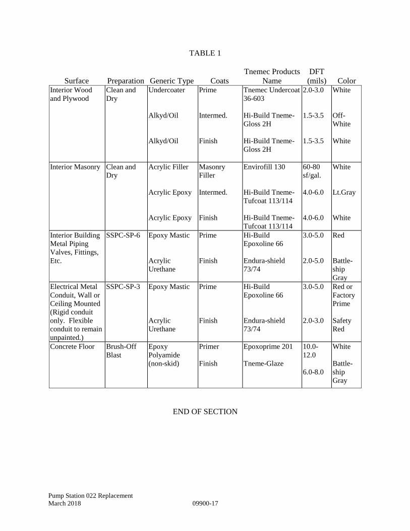
Pump Station 022 Replacement
March 2018 09900-17
TABLE 1
Surface Preparation Generic Type Coats
Tnemec Products
Name
DFT
(mils) Color Interior Wood
and Plywood
Clean and
Dry
Undercoater
Alkyd/Oil
Alkyd/Oil
Prime
Intermed.
Finish
Tnemec Undercoat
36-603
Hi-Build Tneme-
Gloss 2H
Hi-Build Tneme-
Gloss 2H
2.0-3.0
1.5-3.5
1.5-3.5
White
Off-
White
White
Interior Masonry Clean and
Dry
Acrylic Filler
Acrylic Epoxy
Acrylic Epoxy
Masonry
Filler
Intermed.
Finish
Envirofill 130
Hi-Build Tneme-
Tufcoat 113/114
Hi-Build Tneme-
Tufcoat 113/114
60-80
sf/gal.
4.0-6.0
4.0-6.0
White
Lt.Gray
White
Interior Building
Metal Piping
Valves, Fittings,
Etc.
SSPC-SP-6 Epoxy Mastic
Acrylic
Urethane
Prime
Finish
Hi-Build
Epoxoline 66
Endura-shield
73/74
3.0-5.0
2.0-5.0
Red
Battle-
ship
Gray
Electrical Metal
Conduit, Wall or
Ceiling Mounted
(Rigid conduit
only. Flexible
conduit to remain
unpainted.)
SSPC-SP-3 Epoxy Mastic
Acrylic
Urethane
Prime
Finish
Hi-Build
Epoxoline 66
Endura-shield
73/74
3.0-5.0
2.0-3.0
Red or
Factory
Prime
Safety
Red
Concrete Floor Brush-Off
Blast
Epoxy
Polyamide
(non-skid)
Primer
Finish
Epoxoprime 201
Tneme-Glaze
10.0-
12.0
6.0-8.0
White
Battle-
ship
Gray
END OF SECTION

Pump Station 022 Replacement
March 2018 09900-18
This Page Intentionally Left Blank
Pump Station 022 Replacement
March 2018 10201-1
SECTION 10201 – METAL WALL LOUVERS
1. GENERAL
1.1 REFERENCES
The publications listed below form a part of this specification to the extent referenced.
The publications are referred to in the text by the basic designation only. The referenced
publications shall be the current effective edition.
THE ALUMINUM ASSOCIATION, INCORPORATED (AA)
AA 45 Designation System for Aluminum Finishes
AIR MOVEMENT AND CONTROL ASSOCIATION, INC. (AMCA)
ANSI/AMCA 500 D Testing Dampers for Rating
ANSI/AMCA 500 L Testing Louvers for Rating
AMCA 511 Certified Ratings Program – Product Rating Manual for
Air Control Devices
AMERICAN SOCIETY FOR TESTING AND MATERIALS (ASTM)
ASTM B 209 Aluminum and Aluminum-Alloy Sheet and Plate
ASTM B 221 Aluminum and Aluminum-Alloy Extruded Bars, Rods,
Wire, Profiles, and Tubes
1.2 SUBMITTALS
Submit the following in accordance with Section 01330, "Submittal Procedures."
SD-02 Shop Drawings
Wall louvers
Show all information necessary for fabrication and installation of louvers. Indicate
materials, sizes, thickness, fastenings, and profiles.
Pump Station 022 Replacement
March 2018 10201-2
SD-04 Samples
Wall louvers
Colors of finishes shall closely approximate colors indicated. Where color is not
indicated, submit the manufacturer's standard colors to the Owner for selection.
1.3 DELIVERY, STORAGE, AND PROTECTION
Deliver materials to the site in an undamaged condition. Carefully store materials off the
ground to provide proper ventilation, drainage, and protection against dampness.
Louvers shall be free from nicks, scratches, and blemishes. Replace defective or
damaged materials with new.
2. PRODUCTS
2.1 MATERIALS
2.1.1 Aluminum Sheet
ASTM B 209, alloy 3003 or 5005 with temper as required for forming.
2.1.2 Extruded Aluminum
ASTM B 221, alloy 6063-T5 or -T52.
2.2 METAL WALL LOUVERS
Weather resistant type, with bird screens and made to withstand a wind load of not less
than 30 pounds per square foot. Wall louvers shall bear the AMCA certified ratings
program seal for air performance and water penetration in accordance with AMCA 500
L, AMCA 500 D, and AMCA 511. The rating shall show a water penetration of 0.20 or
less ounce per square foot of free area at a free velocity of 800 feet per minute.
2.2.1 Extruded Aluminum Louvers
Fabricated of extruded 6063-T5 or -T52 aluminum with a wall thickness of not less than
0.081 inch.
2.2.2 Formed Metal Louvers
Formed of zinc-coated steel sheet not thinner than 16 U.S. gage, or aluminum sheet not
less than 0.08 inch thick.
Pump Station 022 Replacement
March 2018 10201-3
2.2.3 Shutters
Provide anodized aluminum gravity shutter at each louver location. Gravity shutter shall
open in the direction of flow as indicated.
2.2.4 Screens and Frames
For aluminum louvers, provide 1/2 inch square mesh, 14 or 16 gage aluminum or 1/4
inch square mesh, 16 gage aluminum bird screening. Mount screens in removable,
rewireable frames of same material and finish as the louvers between louver and shutter.
2.3 FASTENERS AND ACCESSORIES
Provide stainless steel screws and fasteners for aluminum louvers. Provide other
accessories as required for complete and proper installation.
2.4 FINISHES
2.4.1 Aluminum
Provide factory-applied anodic coating. Clean exposed aluminum surfaces and apply an
anodized finish conforming to AA 45 Designation System for Aluminum Finishes,
integral color anodized, Architectural Class II.
3. EXECUTION
3.1 INSTALLATION
3.1.1 Fixed Wall Louvers
Install using stops or moldings, flanges, strap anchors, or jamb fasteners as appropriate
for the wall construction and in accordance with manufacturer's recommendations.
3.2 PROTECTION FROM CONTACT OF DISSIMILAR MATERIALS
3.2.1 Aluminum
Where aluminum contacts metal other than zinc, paint the dissimilar metal with a primer
and two coats of aluminum paint.
3.2.2 Cement-based Substrates
Paint metal in contact with mortar, concrete, or other masonry materials with alkali-
resistant coatings such as heavy-bodied bituminous paint.
END OF SECTION

Pump Station 022 Replacement
March 2018 10201-4
This Page Intentionally Left Blank
Pump Station 022 Replacement
March 2018 11330-1
SECTION 11330 — NON-CLOG SUBMERSIBLE CENTRIFUGAL PUMPS AND DRIVES
1. GENERAL
1.1 Summary
1.1.1 This section addresses the work related to furnishing and installing all supervision, labor,
materials and equipment in the work for non-clog, submersible centrifugal pumps and
drives.
1.1.2 Related Sections
01330 Submittal Procedures
15060 Basic Mechanical Materials and Methods
16010 Electrical Basic Requirements
16410 Pump Control Panel
16482 Motor Starters
16690 Variable Frequency Drive
16920 Programmable Logic Controller
1.2 Submittals
Submit shop drawings and manufacturers data in accordance with the provisions of
Division I, General Provisions, and Section 01330 — Submittal Procedures, and
• Certified performance curves in accordance with Hydraulic Institute Standards
signed and sealed by the manufacturer’s licensed professional engineer.
• Certified copies of results of hydrostatic test.
• Setting plans which shall include
o Anchor bolt layout
o Anchor bolt dimensions
o Outline dimension and weights of pumps, guiderail system and control
enclosures
• Pumps: Submittal data and drawings shall include:
o Manufacturer, type, and model number
o Assembly drawing, nomenclature and material list, O&M manual, and parts list
o Type, manufacturer, model number
o Impeller type, diameter, sphere size passing, number of vanes and identification
number
o Complete motor performance data including: rating: voltage/phase/frequency
Pump Station 022 Replacement
March 2018 11330-2
o Complete performance curve(s) showing full range (shutoff to run-out) head vs.
capacity, NPSHR, hydraulic efficiency, motor active (KW) input power, and
shaft power (BHP)
o A copy of the system head curves and recommend pump performance curves are
included in Division IX, Supplemental Specifications. These curves included
high and low HRSD head conditions, if appropriate, and a friction factor of
C=100 and C=120. When the CONTRACTOR is submitting a proposed pump
curve for shop drawing review, the proposed pump curve shall be plotted on top
of the system curves included in Division IX Supplemental Specifications and
submitted for review.
• Location and description of Service Centers and spare parts stock.
• The manufacturer shall indicate, by arrows to points on the flow versus head in feet
of water curves, the limits recommended for stable operation, between which the
pumps are to be operated to prevent surging, cavitation and vibration. The stable
operating range shall meet the hydraulic performance requirements of the proposed
system.
• Bearing life projection and warranty at the specified operating condition
1.3 References
1.3.1 The publications listed below form a part of this specification to the extent referenced. The
publications are referred to in the text by basic designation only. The referenced
publications shall be the current effective edition.
• HI B Hydraulic Institute Standards for Centrifugal, Rotary, and Reciprocating Pumps.
• ASTM B American Society for Testing and Materials.
• ASTM A48 Standard Specification for Gray Iron Castings
• AISI B American Iron and Steel Institute
• ANSI B American National Standards Institute
2. PRODUCTS
2.1 Products
Pumps shall be in accordance with the Contract Documents, or an approved equal.
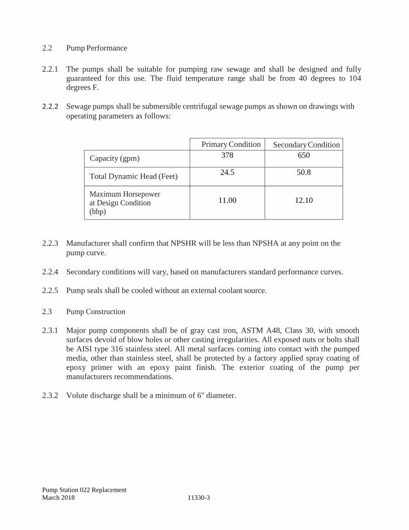
Pump Station 022 Replacement
March 2018 11330-3
2.2 Pump Performance
2.2.1 The pumps shall be suitable for pumping raw sewage and shall be designed and fully
guaranteed for this use. The fluid temperature range shall be from 40 degrees to 104 degrees F.
2.2.2 Sewage pumps shall be submersible centrifugal sewage pumps as shown on drawings with
operating parameters as follows:
Primary Condition Secondary Condition
Capacity (gpm) 378 650
Total Dynamic Head (Feet) 24.5
50.8
Maximum Horsepower at Design Condition (bhp)
11.00
12.10
2.2.3 Manufacturer shall confirm that NPSHR will be less than NPSHA at any point on the
pump curve.
2.2.4 Secondary conditions will vary, based on manufacturers standard performance curves.
2.2.5 Pump seals shall be cooled without an external coolant source.
2.3 Pump Construction
2.3.1 Major pump components shall be of gray cast iron, ASTM A48, Class 30, with smooth
surfaces devoid of blow holes or other casting irregularities. All exposed nuts or bolts shall
be AISI type 316 stainless steel. All metal surfaces coming into contact with the pumped
media, other than stainless steel, shall be protected by a factory applied spray coating of
epoxy primer with an epoxy paint finish. The exterior coating of the pump per
manufacturers recommendations.
2.3.2 Volute discharge shall be a minimum of 6" diameter.
Pump Station 022 Replacement
March 2018 11330-4
2.3.3 Sealing design shall incorporate metal to metal contact between machined surfaces.
Pump/Motor unit mating surfaces where watertight sealing is required shall be machined
and fitted with Nitrile or Viton rubber O-rings. Joint sealing will be the result of controlled
compression of rubber O-rings in two planes, and O-ring contact of four sides without the
requirement of a specific bolt torque limit.
2.4 Cooling System
Motors shall be externally cooled by submergence in the pumped media.
2.5 Cables
2.5.1 The cable entry seal design shall insure a watertight and submersible seal. Each motor shall
be fitted with sufficient cable so that no splices are required between the pump and the
pump starters. The CONTRACTOR shall supply two separate cables for each pump and
coordinate the required cable length IOT the installation as shown on the drawing. Control
wiring or sensor cables shall be run in separate conduit than power cable or wiring. Cable
restraints and supports shall be suitable to support cable without damage to the cable and
be 316 stainless steel.
2.5.2 The power cable shall be Type ATC@, ASOW-A@, or AW@ and sized according to the
NEC and ICEA standards and shall be of sufficient length to reach the control panel
without the need of any splices. The outer jacket of the cable shall be oil resistant rubber.
2.6 Motors
2.6.1 Motor shall be furnished with nameplate indicating voltage, phase, current, design type;
service factor; insulation class; rotation; speed; current, power factor, and start (max.
Inrush) current; locked rotor current; NEC code letter; and motor torque as a continuous
function through the motor start cycle from no rotation to synchronous speed.
2.6.2 The pump motor shall be induction type with a squirrel cage rotor, shell type design,
housed in an air or oil filled, watertight chamber, NEMA B type. Motor shall be UL listed
for use in Class I, Division 1, Group C and D hazardous locations. The stator windings and
stator leads shall be insulated with moisture resistant Class F installation rated for 311
degrees F. The stator shall be dipped and baked three times in Class F varnish, and shall be
heat-shrink fitted into the stator housing. The use of bolts, pins, or other fastening devices
requiring penetration of the stator housing is not acceptable.
2.6.3 The motor shall be specifically designed for submersible pump usage and designed for
continuous duty pumping media of up to 104 degrees F and capable of up to 10 evenly
spaced starts per hour. The motor and cable shall be capable of continuous submergence
underwater to a depth of 65 feet without loss of watertight integrity.
Pump Station 022 Replacement
March 2018 11330-5
2.6.4 Thermal switches shall be imbedded in the stator lead coils to monitor the temperature of
each phase winding. These thermal switches shall be set to open at 125 degrees C, and
shall be used in conjunction with and supplemental to external motor overload protection;
and shall be connected to the control panel.
2.6.5 Dual moisture detection probes shall detect the entrance of moisture and provide an alarm.
The moisture detection probes shall detect the entrance of moisture in the stator and lower
seal cavity and send an alarm to the control panel. Single probe or float switch sensors
shall not be allowed.
2.6.6 Motors shall be suitable for operation with controllers as indicated on the plans. Motors for
Variable Frequency Drive applications shall be rated for induction inverter duty.
2.6.7 The combined service factor (combined effect of voltage, frequency and specific gravity)
shall be a minimum of 1.15 at an operating temperature of 104 degrees F ambient and with
a temperature rise not to exceed 190 degrees F. A performance chart shall be provided
showing curves for torque, current, power factor, input/output kW and efficiency. This
chart shall also include data on starting and no-load characteristics.
2.6.8 The motor horsepower shall be adequate so that the pump is non-overloading throughout
the entire pump performance curve.
2.7 Bearings
The pump shaft shall rotate on bearings with a minimum L10 bearing life of 50,000 hours at any point along the usable portion of the pump curve.
2.8 Mechanical Seal
2.8.1 Each pump shall be provided with a tandem mechanical shaft seal system consisting of
two totally independent seal assemblies. The lower seal shall be independent of the
impeller hub. The seals shall operate in an oil reservoir that hydro-dynamically lubricates
the lapped seal faces at a constant rate. The lower, primary seal unit, located between the
pump and the oil chamber, shall contain one stationary and one positively driven rotating
tungsten carbide or silicon carbide ring. The upper, secondary seal unit, located between
the oil chamber and the motor housing, shall contain one stationary tungsten carbide seal
ring and one positively driven rotating silicon carbide seal ring. Each seal interface shall be
held in contact by its own spring system. The seals shall require neither maintenance nor
adjustment and shall be capable of operating in either clockwise or counter clockwise
direction rotation without damage or loss of seal. For special applications, other seal face
materials shall be available.
2.8.2 Each pump shall be provided with an oil chamber for the shaft sealing system. The oil
chamber shall be design to prevent overfilling and to provide oil expansion capacity. The
drain and inspection plug, with position anti-leak seal shall be easily accessible from the
outside. The seal system shall not rely upon the pumped media for lubrication.
Pump Station 022 Replacement
March 2018 11330-6
2.9 Pump Shaft
Pump and motor shaft shall be a solid continuous shaft. The pump shaft is an extension of
the motor shaft. Couplings shall not be acceptable. The pump shaft shall be of AISI Type
416 stainless steel, and shall be completely isolated from the pumped liquid.
2.10 Impeller
Impellers shall be non-clog type, manufactured of close-grained cast iron conforming to
ASTM A48, Class 30. Impellers shall be of one piece, single suction, enclosed radial flow
design with well-rounded leading vane edges and a thick hydrofoil shape with large
openings to prevent the accumulation of solids and stringy material. The clearance between
the impeller outside diameter and cutwater shall be capable of passing a 3-inch sphere.
Impellers shall be statically and dynamically balanced and secured to a straight or tapered
fit on the pump shaft by means of a bolt, washer and key. The arrangement shall be such
that the impeller cannot be loosened by operating torque in either forward or reverse
rotation.
2.11 Volute
Volutes shall be made of close-grained cast iron conforming to ASTM A48, Class 30 and
of one piece design with smooth fluid passages large enough to pass any size solid that can
pass through the impeller. Volutes shall be flanged with discharge as shown on the
Drawings. Diffusion vanes are not permitted. Volutes shall be furnished with large
cleanout openings located at the impeller centerline, to allow access to the impeller.
Flanges shall be 125 lbs. raised or flat faced flanges in accordance with ANSI B 16.1
drilling. Casing shall be hydrostatically tested to 1.5 times the design head or 1.25 times
the shutoff head, whichever is greater.
2.12 Wear Rings
Pumps shall be equipped with replaceable stationary and mobile wear rings.
2.12.1 The stationary wear ring shall be stainless steel with a Brinell hardness of 425-475.
2.12.2 The mobile wear ring shall be stainless steel with a Brinell hardness of 325-350.
2.13 Protection
2.13.1 All stators shall incorporate thermal switches in series to monitor the temperature of each
phase winding. Should high temperature occur, the thermal switches shall open, stop the
motor and activate an alarm.
2.13.2 A leakage sensor shall be provided to detect water in the stator chamber. When
activated, the leakage sensor will stop the motor and activate an alarm.
Pump Station 022 Replacement
March 2018 11330-7
2.13.3 Each pump shall be provided with its own self contained control and status module, which
will be mounted within the pump control panel. This module shall provide a single point
within the control system for pump sensor output processing. The module shall have a
manual reset.
2.13.4 All alarms connected to the control and status module shall be integrated with the RTU/PLC panel.
2.14 Guide Rail Bracket and Discharge Base
2.14.1 The sliding bracket assembly shall be a part of the pumping unit and constructed such that,
when the pumping unit is lowered onto the discharge base elbow, the knifing action of the vertical metal to metal seal will provide a self-cleaning, non-clogging, non-sparking assembly.
2.14.2 Two 316 stainless steel rails shall be provided to guide the pump when it is being raised or
lowered in the wet well. They shall mount on the discharge base/elbow provided by the pump manufacturer. The rails shall guide the pump into position on the discharge elbow as it is lowered into place. The rail guide system shall be mounted to the wall with intermediate 316 stainless steel brackets at no more than 8- foot intervals using 316 stainless steel adhesive anchors.
2.14.3 The discharge base shall be rigid, set and secured to the concrete floor of the wetwell and
shall be capable of supporting the total weight of the pumping unit. The base shall be
bolted directly to the wetwell bottom slab using 316 SS adhesive anchors or cast in place
SS anchor bolts. The discharge base shall include a 90 degree elbow with a 125 pound
ANSI flange discharging vertically, be suitable for the pump and be of manufactured of
either cast or ductile iron.
2.14.4 A 316 stainless steel cable shall be provided for each pump with a suitable stainless steel
bracket at the top for holding the cable within easy reach through the hatch.
2.15 Spare Parts
2.15.1 One spare full diameter impeller and one spare set of mechanical seals.
3. EXECUTION
3.1 Installation
3.1.1 Pumping equipment shall be installed in accordance with recommendations of the
manufacturer, and the details shown on the contract drawings. A copy of the installation
instructions shall be made available to the ENGINEER and the CITY’S Construction
Inspector prior to equipment installation.
3.1.2 In the event any equipment fails to meet the specifications, it shall be modified and retested
in accordance with these specifications.
Pump Station 022 Replacement
March 2018 11330-8
3.2 Pump Testing
3.2.1 After installation, the pumping system shall be field tested using potable water. Water will
be furnished by the CITY at no cost to the CONTRACTOR. The CONTRACTOR shall be responsible for conveying the water to the site and providing required meter and back-flow prevention check valve assembly. Each pump shall be cycled through the sequence of operation “pump on” as the level rises in the wet well and then “pump off’ during draw down.
3.2.2 Each pump shall operate over its intended operating range without undue noise, vibration,
or cavitation. The CONTRACTOR shall monitor and record vibration at three
symmetrically located points on each pump at maximum and minimum speed and supply
data to the CITY. Each pump shall operate within the tolerances established in the
Hydraulics Institute (HI) standards and within an acceptable range on the certified pump
curve provided by the manufacturer.
3.2.3 Upon completion of the installation, on-site testing, and before acceptance by the CITY,
the Pump Manufacturer or the authorized Pump Manufacturer’s Representative shall
submit a written statement that the pump installation has been completed in accordance
with the manufacturer’s recommendations.
3.3 Manufacturer’s Representative
3.3.1 Provide manufacturer’s representative for startup.
3.3.2 Prior to Operational Testing, the CONTRACTOR shall have the manufacturer do the
following:
• Megger test the stator and power cables.
• Check proper rotation.
• Check power supply voltage.
• Measure motor operating load and no load current.
• Check level control operation and sequence.
3.3.3 During Final Acceptance Testing, the manufacturer's service representative shall review
recommended operation and maintenance procedures with the CITY’S personnel. Prior to
Final Acceptance testing the pump manufacturer shall submit a written report that the
pump(s) are satisfactorily installed in accordance with the manufacturer’s
recommendations.
3.4 Operating Manuals
3.4.1 The pumps shall be supplied with four (4) copies of an Operating Manual with detailed
pump assembly drawings, warranty, and component lists.
END OF SECTION
Pump Station 022 Replacement
March 2018 15050-1
SECTION 15050 - BASIC MECHANICAL MATERIALS AND METHODS
1. GENERAL
1.1 REFERENCES
The publications listed below form a part of this specification to the extent referenced. The
publications are referred to in the text by the basic designation only. The referenced
publications shall be the current effective edition.
AMERICAN SOCIETY FOR TESTING AND MATERIALS (ASTM)
ASTM B 117 Operating Salt Spray (Fog) Apparatus
1.2 RELATED REQUIREMENTS
This section applies to all sections of Division 15, "Mechanical" of this project
specification, unless specified otherwise in the individual section.
1.3 QUALITY ASSURANCE
1.3.1 Material and Equipment Qualifications
Provide materials and equipment that are standard products of manufacturers regularly
engaged in the manufacture of such products, which are of a similar material, design, and
workmanship. Standard products shall have been in satisfactory commercial or industrial
use for 2 years prior to bid opening. The 2-year use shall include applications of
equipment and materials under similar circumstances and of similar size. The product
shall have been for sale on the commercial market through advertisements,
manufacturers' catalogs, or brochures during the 2-year period.
1.3.2 Alternative Qualifications
Products having less than a two-year field service record will be acceptable if a certified
record of satisfactory field operation for not less than 6,000 hours, exclusive of the
manufacturer's factory or laboratory tests, can be shown.
1.3.3 Service Support
The equipment items shall be supported by service organizations. Submit a certified list
of qualified permanent service organizations for support of the equipment which includes
their addresses and qualifications. These service organizations shall be reasonably
convenient to the equipment installation and able to render satisfactory service to the
equipment on a regular and emergency basis during the warranty period of the contract.
Pump Station 022 Replacement
March 2018 15050-2
1.3.4 Manufacturer's Nameplate
Each item of equipment shall have a nameplate bearing the manufacturer's name, address,
model number, and serial number securely affixed in a conspicuous place; the nameplate
of the distributing agent will not be acceptable.
1.3.5 Modification of References
In each of the publications referred to herein, consider the advisory provisions to be
mandatory, as though the word, "shall" had been substituted for "should" wherever it
appears. Interpret references in these publications to the "authority having jurisdiction,”
or words of similar meaning, to mean the Owner.
1.3.5.1 Definitions
For the International Code Council (ICC) Codes referenced in the contract documents,
advisory provisions shall be considered mandatory, the word "should" shall be interpreted
as "shall." Reference to the "code official" shall be interpreted to mean the "Owner." For
leased facilities, references to the "owner" shall be interpreted to mean the "lessor."
References to the "permit holder" shall be interpreted to mean the "Contractor."
1.4 DELIVERY, STORAGE, AND HANDLING
Handle, store, and protect equipment and materials to prevent damage before and during
installation in accordance with the manufacturer's recommendations, and as approved by
the Owner. Replace damaged or defective items.
1.5 ELECTRICAL REQUIREMENTS
Furnish motors, controllers, disconnects and contactors with their respective pieces of
equipment. Motors, controllers, disconnects and contactors shall conform to and have
electrical connections provided in accordance with requirements of DIVISION 16
"Electrical." Furnish internal wiring for components of packaged equipment as an
integral part of the equipment. Extended voltage range motors will not be permitted.
Controllers and contactors shall have a maximum of 120 volt control circuits, and shall
have auxiliary contacts for use with the controls furnished. When motors and equipment
furnished are larger than sizes indicated, the cost of additional electrical service and
related work shall be included under the section that specified that motor or equipment.
Power wiring and conduit for field installed equipment shall be provided under and
conform to the requirements of DIVISION 16 "Electrical."
Pump Station 022 Replacement
March 2018 15050-3
1.6 INSTRUCTION TO OWNER MAINTENANCE PERSONNEL
When specified in other sections, furnish the services of competent instructors to give full
instruction to the Owner's designated personnel in the adjustment, operation, and
maintenance, including pertinent safety requirements, of the specified equipment or
system. Instructors shall be thoroughly familiar with all parts of the installation and shall
be trained in operating theory as well as practical operation and maintenance work.
Instruction shall be given during the first regular work week after the equipment or
system has been accepted and turned over to the Owner for regular operation. The
number of man-days (8 hours per day) of instruction furnished shall be as specified in the
individual section. When more than 4 man-days of instruction are specified, use
approximately half of the time for classroom instruction. Use other time for instruction
with the equipment or system.
When significant changes or modifications in the equipment or system are made under
the terms of the contract, provide additional instruction to acquaint the operating
personnel with the changes or modifications.
1.7 ACCESSIBILITY
Install all work so that parts requiring periodic inspection, operation, maintenance, and
repair are readily accessible. Install concealed valves, expansion joints, controls,
dampers, and equipment requiring access, in locations freely accessible through access
doors.
2. PRODUCTS
Not used.
3. EXECUTION
3.1 PAINTING OF NEW EQUIPMENT
New equipment painting shall be factory applied or shop applied, and shall be as
specified herein, and provided under each individual section.
Pump Station 022 Replacement
March 2018 15050-4
3.1.1 Factory Painting Systems
Manufacturer's standard factory painting systems may be provided subject to certification
that the factory painting system applied will withstand 125 hours in a salt-spray fog test,
except that equipment located outdoors shall withstand 500 hours in a salt-spray fog test.
Salt-spray fog test shall be in accordance with ASTM B 117, and for that test the
acceptance criteria shall be as follows: immediately after completion of the test, the paint
shall show no signs of blistering, wrinkling, or cracking, and no loss of adhesion; and the
specimen shall show no signs of rust creepage beyond 0.125 inch on either side of the
scratch mark.
The film thickness of the factory painting system applied on the equipment shall not be
less than the film thickness used on the test specimen. If manufacturer's standard factory
painting system is being proposed for use on surfaces subject to temperatures above 120
degrees F, the factory painting system shall be designed for the temperature service.
3.1.2 Shop Painting Systems for Metal Surfaces
Clean, pre-treat, prime and paint metal surfaces; except aluminum surfaces need not be
painted. Apply coatings to clean dry surfaces. Clean the surfaces to remove dust, dirt,
rust, oil and grease by wire brushing and solvent degreasing prior to application of paint,
except metal surfaces subject to temperatures in excess of 120 degrees F shall be cleaned
to bare metal.
Where more than one coat of paint is specified, apply the second coat after the preceding
coat is thoroughly dry. Lightly sand damaged painting and retouch before applying the
succeeding coat. Color of finish coat shall be aluminum or light gray.
a. Temperatures Less Than 120 Degrees F: Immediately after cleaning, the metal
surfaces subject to temperatures less than 120 degrees F shall receive one coat of
pretreatment primer applied to a minimum dry film thickness of 0.3 mil, one coat of
primer applied to a minimum dry film thickness of one mil; and two coats of enamel
applied to a minimum dry film thickness of one mil per coat.
b. Temperatures Between 120 and 400 Degrees F: Metal surfaces subject to
temperatures between 120 and 400 degrees F shall receive two coats of 400 degrees
F heat-resisting enamel applied to a total minimum thickness of 2 mils.
c. Temperatures Greater Than 400 Degrees F: Metal surfaces subject to temperatures
greater than 400 degrees F shall receive two coats of 600 degrees F heat-resisting
paint applied to a total minimum dry film thickness of 2 mils.
END OF SECTION
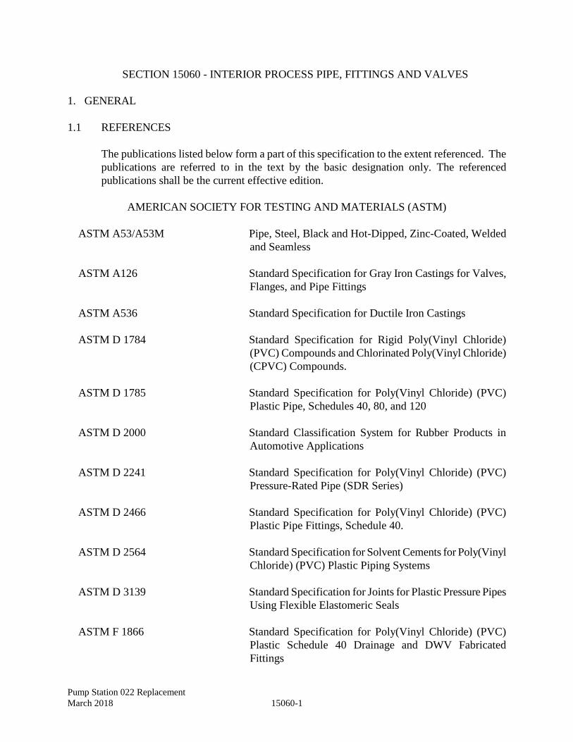
Pump Station 022 Replacement
March 2018 15060-1
SECTION 15060 - INTERIOR PROCESS PIPE, FITTINGS AND VALVES
1. GENERAL
1.1 REFERENCES
The publications listed below form a part of this specification to the extent referenced. The
publications are referred to in the text by the basic designation only. The referenced
publications shall be the current effective edition.
AMERICAN SOCIETY FOR TESTING AND MATERIALS (ASTM)
ASTM A53/A53M Pipe, Steel, Black and Hot-Dipped, Zinc-Coated, Welded
and Seamless
ASTM A126 Standard Specification for Gray Iron Castings for Valves,
Flanges, and Pipe Fittings
ASTM A536 Standard Specification for Ductile Iron Castings
ASTM D 1784 Standard Specification for Rigid Poly(Vinyl Chloride)
(PVC) Compounds and Chlorinated Poly(Vinyl Chloride)
(CPVC) Compounds.
ASTM D 1785 Standard Specification for Poly(Vinyl Chloride) (PVC)
Plastic Pipe, Schedules 40, 80, and 120
ASTM D 2000 Standard Classification System for Rubber Products in
Automotive Applications
ASTM D 2241 Standard Specification for Poly(Vinyl Chloride) (PVC)
Pressure-Rated Pipe (SDR Series)
ASTM D 2466 Standard Specification for Poly(Vinyl Chloride) (PVC)
Plastic Pipe Fittings, Schedule 40.
ASTM D 2564 Standard Specification for Solvent Cements for Poly(Vinyl
Chloride) (PVC) Plastic Piping Systems
ASTM D 3139 Standard Specification for Joints for Plastic Pressure Pipes
Using Flexible Elastomeric Seals
ASTM F 1866 Standard Specification for Poly(Vinyl Chloride) (PVC)
Plastic Schedule 40 Drainage and DWV Fabricated
Fittings
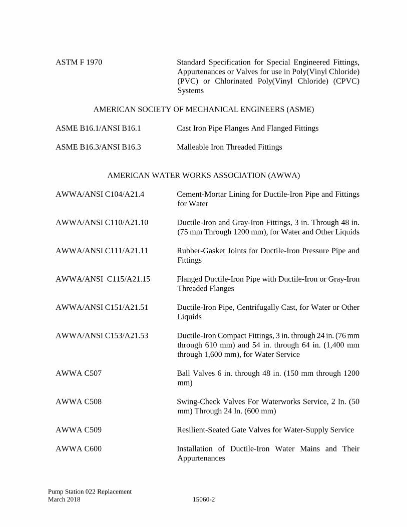
Pump Station 022 Replacement
March 2018 15060-2
ASTM F 1970 Standard Specification for Special Engineered Fittings,
Appurtenances or Valves for use in Poly(Vinyl Chloride)
(PVC) or Chlorinated Poly(Vinyl Chloride) (CPVC)
Systems
AMERICAN SOCIETY OF MECHANICAL ENGINEERS (ASME)
ASME B16.1/ANSI B16.1 Cast Iron Pipe Flanges And Flanged Fittings
ASME B16.3/ANSI B16.3 Malleable Iron Threaded Fittings
AMERICAN WATER WORKS ASSOCIATION (AWWA)
AWWA/ANSI C104/A21.4 Cement-Mortar Lining for Ductile-Iron Pipe and Fittings
for Water
AWWA/ANSI C110/A21.10 Ductile-Iron and Gray-Iron Fittings, 3 in. Through 48 in.
(75 mm Through 1200 mm), for Water and Other Liquids
AWWA/ANSI C111/A21.11 Rubber-Gasket Joints for Ductile-Iron Pressure Pipe and
Fittings
AWWA/ANSI C115/A21.15 Flanged Ductile-Iron Pipe with Ductile-Iron or Gray-Iron
Threaded Flanges
AWWA/ANSI C151/A21.51 Ductile-Iron Pipe, Centrifugally Cast, for Water or Other
Liquids
AWWA/ANSI C153/A21.53 Ductile-Iron Compact Fittings, 3 in. through 24 in. (76 mm
through 610 mm) and 54 in. through 64 in. (1,400 mm
through 1,600 mm), for Water Service
AWWA C507 Ball Valves 6 in. through 48 in. (150 mm through 1200
mm)
AWWA C508 Swing-Check Valves For Waterworks Service, 2 In. (50
mm) Through 24 In. (600 mm)
AWWA C509 Resilient-Seated Gate Valves for Water-Supply Service
AWWA C600 Installation of Ductile-Iron Water Mains and Their
Appurtenances
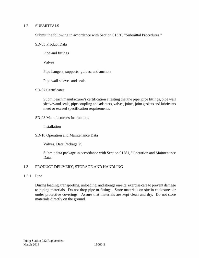
Pump Station 022 Replacement
March 2018 15060-3
1.2 SUBMITTALS
Submit the following in accordance with Section 01330, "Submittal Procedures."
SD-03 Product Data
Pipe and fittings
Valves
Pipe hangers, supports, guides, and anchors
Pipe wall sleeves and seals
SD-07 Certificates
Submit each manufacturer's certification attesting that the pipe, pipe fittings, pipe wall
sleeves and seals, pipe coupling and adapters, valves, joints, joint gaskets and lubricants
meet or exceed specification requirements.
SD-08 Manufacturer's Instructions
Installation
SD-10 Operation and Maintenance Data
Valves, Data Package 2S
Submit data package in accordance with Section 01781, "Operation and Maintenance
Data."
1.3 PRODUCT DELIVERY, STORAGE AND HANDLING
1.3.1 Pipe
During loading, transporting, unloading, and storage on-site, exercise care to prevent damage
to piping materials. Do not drop pipe or fittings. Store materials on site in enclosures or
under protective coverings. Assure that materials are kept clean and dry. Do not store
materials directly on the ground.
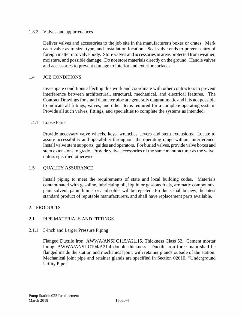
Pump Station 022 Replacement
March 2018 15060-4
1.3.2 Valves and appurtenances
Deliver valves and accessories to the job site in the manufacturer's boxes or crates. Mark
each valve as to size, type, and installation location. Seal valve ends to prevent entry of
foreign matter into valve body. Store valves and accessories in areas protected from weather,
moisture, and possible damage. Do not store materials directly on the ground. Handle valves
and accessories to prevent damage to interior and exterior surfaces.
1.4 JOB CONDITIONS
Investigate conditions affecting this work and coordinate with other contractors to prevent
interference between architectural, structural, mechanical, and electrical features. The
Contract Drawings for small diameter pipe are generally diagrammatic and it is not possible
to indicate all fittings, valves, and other items required for a complete operating system.
Provide all such valves, fittings, and specialties to complete the systems as intended.
1.4.1 Loose Parts
Provide necessary valve wheels, keys, wrenches, levers and stem extensions. Locate to
assure accessibility and operability throughout the operating range without interference.
Install valve stem supports, guides and operators. For buried valves, provide valve boxes and
stem extensions to grade. Provide valve accessories of the same manufacturer as the valve,
unless specified otherwise.
1.5 QUALITY ASSURANCE
Install piping to meet the requirements of state and local building codes. Materials
contaminated with gasoline, lubricating oil, liquid or gaseous fuels, aromatic compounds,
paint solvent, paint thinner or acid solder will be rejected. Products shall be new, the latest
standard product of reputable manufacturers, and shall have replacement parts available.
2. PRODUCTS
2.1 PIPE MATERIALS AND FITTINGS
2.1.1 3-inch and Larger Pressure Piping
Flanged Ductile Iron, AWWA/ANSI C115/A21.15, Thickness Class 52. Cement mortar
lining, AWWA/ANSI C104/A21.4 double thickness. Ductile iron force main shall be
flanged inside the station and mechanical joint with retainer glands outside of the station.
Mechanical joint pipe and retainer glands are specified in Section 02610, “Underground
Utility Pipe."
Pump Station 022 Replacement
March 2018 15060-5
2.1.1.1 Fittings
Ductile-Iron or Gray-Iron, AWWA/ANSI C110/A21.10 or AWWA/ANSI C153/A21.53.
Cement mortar lining, AWWA/ANSI C104/A21.4 double thickness.
2.1.1.2 Gaskets
Styrene Butadiene Rubber, 80 Durameter hardness, conforming to ASTM D2000, Class AA
or BA, smooth finish.
2.1.2 Metal Pressure Piping Smaller than 3-inches
ASTM A53/A53M, Seamless, hot-dip galvanized. Schedule 40, unless otherwise indicated
on the Contract Drawings. ASME B16.1/ANSI B16.1, 125 Class flanges as applicable.
2.1.2.1 Fittings
2.1.2.1.1 Threaded
Malleable Iron, ASME B16.3/ANSI B16.3, 150 Class
2.1.2.1.2 Flanged
Cast Iron, ASME B16.1/ANSI B16.1, 125 Class
2.1.2.1.3 Unions
Threaded Malleable Iron, FS WW-U-531, Class 1
2.1.3 Plastic Pressure Piping Smaller than 3-inches
ASTM D 1785, Schedule 40 PVC piping. Solvent welded joints per ASTM D 2564. Fittings
shall conform to ASTM D 2466 or ASTM F 1970.
2.1.4 Drain, Waste, and Vent Piping
ASTM D 1785, Schedule 40 PVC piping. Solvent welded joints per ASTM D 2564. Fittings
shall conform to ASTM D 2466 or ASTM F 1866.
Pump Station 022 Replacement
March 2018 15060-6
2.2 PIPE ACCESSORIES
2.2.1 Wall and Floor Sleeves and Pipes
Cast Iron per ASTM A126, Class B or Ductile Iron per ASTM A536, Grade 60-40-18.
2.2.2 Wall and Floor Seals
2.2.2.1 Perpendicular Penetration Seals
Seals constructed of an assembly of synthetic rubber links connected with corrosion resistant
stainless steel bolts shall be used to seal the space between wall sleeve and carrier pipe for
pipes entering perpendicular to the concrete surface. When the bolts are tightened, Delrin
plastic pressure plates compress the rubber links to fill the annular space between the pipe
and the wall sleeve to form a watertight seal. Seals shall be manufactured by Link Seal or
approved equal.
2.2.2.2 Non-Perpendicular and Below Grade Penetration Seals
Rubber boot connectors with stainless steel bands meeting ASTM C 923, ASTM C 1478,
and ASTM F 2510, as applicable for the application, by Kor-N-Seal, PSX, or approved equal
shall be used for conduits and pipes passing through non-perpendicular penetrations or where
entering structures below grade. Place non-shrink grout in annular space (inside and outside,
as applicable) and finish flush with surface of concrete.
2.2.3 Flange Adapters
For joining plain-end pipe to flanged valves, fittings, and pumps. Flanged per ASME
B16.1/ANSI B16.1, 125 Class.
2.2.4 Transition Couplings
To connect pipes of different outside diameters. High-grade cast-iron sleeves with ductile-
iron follower flanges. Flanged per ASME B16.1/ANSI B16.1, 125 Class or Mechanical Joint
per AWWA/ANSI C111/A21.11.
2.2.5 Pipe Hangers
Figure 260 as manufactured by Grinnell Corp. or equal.
2.2.6 Pipe Supports
Figure 199 as manufactured by Grinnell Corp. or equal.
Pump Station 022 Replacement
March 2018 15060-7
2.3 GATE VALVES
AWWA C509, resilient seated, non-rising stem, 200 psi working pressure, open left
(counterclockwise), flanged per ASME B16.1/ANSI B16.1, 125 Class, unless otherwise
noted. One valve wrench shall be provided for every three valves installed in the project.
Provide extension stems (nut operated) where shown on the drawings, otherwise valves shall
be hand wheel operated. Gate valves shall be as manufactured by Mueller, Kennedy, Clow
or approved equal.
2.4 CHECK VALVES
AWWA C508, cast-iron body, outside lever and weight, stainless steel hinge pin, non-shock
working pressure 200 psi, flanged per ASME B16.1/ANSI B16.1, 125 Class, unless
otherwise noted. Check valves shall be as manufactured by Mueller, Kennedy, Clow or
approved equal.
2.5 PRESSURE GAUGES (LIQUID SERVICE)
Compound pressure and vacuum gauge shall be carbon steel body, carbon steel flanges,
neoprene sleeve, ethylene glycol and water filled, minimum 4 inch dial size, stainless steel
dial, black lines and numbers. Pressure range shall be 0-200 feet water column positive
pressure and 0 to 30 inches mercury for vacuum, graduations and figure intervals
proportioned to range, accuracy to 1% of full scale range. Gauge nipple size shall be 1/2 inch
minimum. Provide for each pump discharge.
2.6 VACUUM GAUGES
Carbon steel body, carbon steel flanges, neoprene sleeve, glycerin filled, minimum 4 inch
dial size, stainless steel dial, black lines and numbers. Pressure range shall be 0-30 inches
mercury vacuum, 1 inch graduations and 5 inch figure intervals, accuracy to 1% of full scale
range. Gauge nipple size shall be 1/2 inch minimum. Provide on suction side of pumps for
suction lift pump installations.
2.7 PIPE SUPPORTS
Piping within the wet well (conduits, exhaust ducts, vent pipe, etc.) shall be supported with
aluminum or stainless steel supports securely anchored to the wall with stainless steel
fasteners. Galvanized components will not be accepted.
Pump Station 022 Replacement
March 2018 15060-8
3. EXECUTION
3.1 INTERIOR PROCESS PIPING INSTALLATION
3.1.1 Pipe Layout in Buildings
Coordinate work to prevent interference between architectural, structural, electrical and
mechanical features; the Contract Drawings are generally diagrammatic due to their small
scale. Provide such offsets, fittings and other items as may be required to suit conditions.
Do not place joints or fittings over switchboards, panels, motors or other electrical
equipment. The completed installation shall present a neat, orderly appearance; do not block
openings or passageways; run piping parallel to the walls of buildings or structures. Provide
clearance between piping, walls, floors, machinery and equipment to prevent the
transmission of noise and vibration. Orient handwheels, levers, valve operators and other
valve actuators for convenience of operation; set gate valves with the stem above the
horizontal. Cut pipe to measurements established at the site and install without springing or
forcing; make changes in direction with fittings. Connect ferrous piping to non-ferrous
piping with dielectric couplings.
3.1.2 Equipment Connections
Make connections to pumps and other equipment in a manner to eliminate strains on piping
and equipment. Install unions or flanges adjacent to equipment and wherever their use will
facilitate removal of equipment.
3.1.3 Wall Sleeves and Wall Pipes
Provide pipes passing through concrete construction with wall sleeves or wall pipes, as
indicated on the Contract Drawings. Set wall sleeves and wall pipes of the required size
during construction of the wall, foundation, or slab.
3.1.4 Wall Seals
Provide watertight wall seals between pipe and wall sleeve where pipes penetrate building
walls, foundations, or slabs. Install seal in accordance with manufacturer’s
recommendations. After installation of carrier pipe and pipe seal, place non-shrink grout in
annular space (both faces) and finish flush with surface of concrete.
3.1.5 Flanged Joints
Tighten flange bolts so that the gasket is uniformly compressed and sealed; do not distort
flanges; do not exceed manufacturer's recommended maximum torque. Leave flange bolts
with ends projecting 1/8" to 1/4" beyond the face of the nut after tightening.
Pump Station 022 Replacement
March 2018 15060-9
3.1.6 Threaded Joints
Cut threads full and clean with sharp dies; ream ends of pipe after threading and before
assembly to remove burrs; leave not more than three pipe threads exposed at each
connection; use joint compound or thread tape on the male thread only.
3.1.7 Solvent Welded Joints
Make joints in pipe and fittings in accordance with the procedures and techniques in ASTM
D2855.
3.1.8 Drain Pipe
Floor and hatch drains shall discharge into the wet well through check valves. Slope at
minimum 1/8 inch per foot as indicated on the drawings.
3.2 PIPE SUPPORTS
Support piping from structural construction using pipe hangers, pipe riser clamps and pipe
clamp hangers in conjunction with beam clamps, brackets or other equipment as dictated by
structure construction. Trapeze hangers approved by the Engineer may be used where
several horizontal pipes run closely parallel; secure pipes on trapeze hangers to prevent
sideway motion. Install supports for piping as specified herein.
3.2.1 Vertical Piping
Secure at sufficiently close intervals to keep pipe in alignment and to support weight of pipe
and its contents. Support vertical iron and steel pipe on maximum 5'-0" centers with
stainless steel pipe riser clamps. Support vertical copper tubing at no more than 10'-0"
spacing, using stainless steel pipe riser clamps or pipe clamp hangers at end of runs and at
intermediate points as installation dictates. Support vertical plastic pipe at 4'-0" centers,
using pipe riser clamps or pipe clamp hangers at end of runs and at intermediate points as
installation dictates.
3.2.2 Horizontal Piping
Support at sufficiently close intervals to prevent sagging, thrust restraint, and vibration.
Install hangers or supports at ends of runs or branches and at each change of direction or
alignment. Install stainless steel clevis-type pipe hangers for horizontal iron and steel pipe
on maximum 10'-0" centers. Install stainless steel clevis-type pipe hangers for copper tubing
on 6'-0" centers for 1-1/4" size and smaller, and on 10'-0" centers for copper tubing larger
than 1-1/4" size. Install ring-type pipe hangers for horizontal plastic pipe on maximum 4'-0"
centers, close to every joint, at ends of each branch, and at each change in direction of
elevation; hangers shall not compress, distort, cut or abrade plastic piping and shall permit
free movement of the pipe.
Pump Station 022 Replacement
March 2018 15060-10
3.3 VALVES
Install valves and accessories in accordance with the manufacturer's instructions. Inspect
joint surfaces for structural soundness and thoroughly clean before installation. Check and
adjust valves and accessories for smooth operation.
3.4 GAUGES
Install gauges in accordance with the details on the drawings and manufacturer’s
recommendations.
END OF SECTION
Pump Station 022 Replacement
March 2018 15190-1
SECTION 15190 – HYDROSTATIC TESTING OF PIPING SYSTEMS
1. GENERAL
1.1 REFERENCES
The publications listed below form a part of this specification to the extent referenced. The
publications are referred to in the text by the basic designation only. The referenced
publications shall be the current effective edition.
AMERICAN WATER WORKS ASSOCIATION (AWWA)
AWWA C600 Installation of Ductile-Iron Water Mains and their
Appurtenances
1.2 SUBMITTALS
Submit the following in accordance with Section 01330, "Submittal Procedures"
SD-06 Test Reports
Test procedures
List of test equipment
Testing sequence schedule
Hydrostatic Test Results
SD-07 Certificates
Certification of test pressure gauge calibration and accuracy
1.3 QUALITY ASSURANCE
A. Test Acceptance:
1. No test will be accepted until leakage rate is below specified maximum limits.
2. The contractor shall determine and correct the cause of test failures and retest
until successful test results are achieved.
Pump Station 022 Replacement
March 2018 15190-2
2. PRODUCTS
2.1 HYDROSTATIC TEST EQUIPMENT
Contractor shall supply all equipment necessary for pipeline testing including:
A. Hydro pump
B. Pressure hoses
C. Test connections
D. Pressure relief valve(s)
E. Pressure gauge(s) calibrated to 0.1 lb./sq. inch
3. EXECUTION
3.1 PREPARATION
Install pipe supports in accordance with the plans and specifications. Flush pipeline to
remove debris. Collect and dispose of flushing water and debris in a manner conforming to
regulatory agency requirements.
3.2 HYDROSTATIC TESTING PRESSURE PIPING SYSTEMS
Comply with Section 5 of AWWA C600. Fill entire systems with water and vent air from
the system at least 24 hours before the actual test pressure is applied. Apply the required test
pressure when the water and average ambient temperatures are approximately equal and
constant. Test piping at 1 1/2 times the working pressure (pump discharge pressure) or as
directed by Engineer; avoid excessive pressure on safety devices and mechanical seals.
Maintain test pressure as directed or minimum of 2 hours after the force pump has been
disconnected. Supply makeup water as directed. Visually inspect joints, fittings, and valves
while pipe is under test pressure. Correct all visible leaks and retest as often as necessary
until satisfactory results are achieved.
END OF SECTION
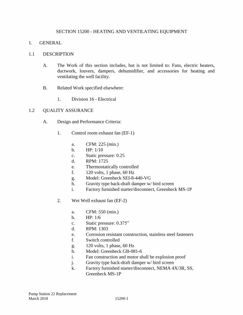
Pump Station 22 Replacement
March 2018 15200-1
SECTION 15200 - HEATING AND VENTILATING EQUIPMENT
1. GENERAL
1.1 DESCRIPTION
A. The Work of this section includes, but is not limited to: Fans, electric heaters,
ductwork, louvers, dampers, dehumidifier, and accessories for heating and
ventilating the well facility.
B. Related Work specified elsewhere:
1. Division 16 - Electrical
1.2 QUALITY ASSURANCE
A. Design and Performance Criteria:
1. Control room exhaust fan (EF-1)
a. CFM: 225 (min.)
b. HP: 1/10
c. Static pressure: 0.25
d. RPM: 1725
e. Thermostatically controlled
f. 120 volts, 1 phase, 60 Hz
g. Model: Greenheck SEI-8-440-VG
h. Gravity type back-draft damper w/ bird screen
i. Factory furnished starter/disconnect, Greenheck MS-1P
2. Wet Well exhaust fan (EF-2)
a. CFM: 550 (min.)
b. HP: 1/6
c. Static pressure: 0.375”
d. RPM: 1303
e. Corrosion resistant construction, stainless steel fasteners
f. Switch controlled
g. 120 volts, 1 phase, 60 Hz
h. Model: Greenheck GB-081-6
i. Fan construction and motor shall be explosion proof
j. Gravity type back-draft damper w/ bird screen
k. Factory furnished starter/disconnect, NEMA 4X/3R, SS,
Greenheck MS-1P
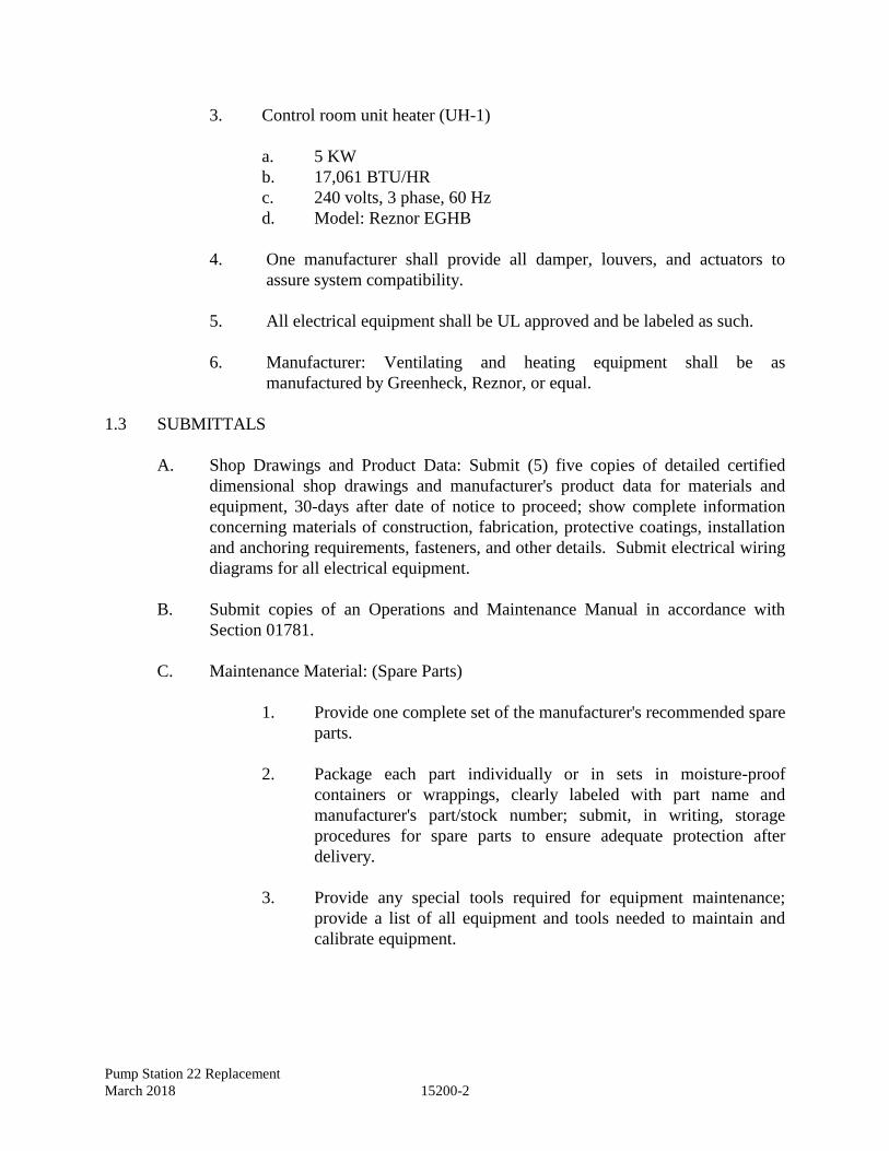
Pump Station 22 Replacement
March 2018 15200-2
3. Control room unit heater (UH-1)
a. 5 KW
b. 17,061 BTU/HR
c. 240 volts, 3 phase, 60 Hz
d. Model: Reznor EGHB
4. One manufacturer shall provide all damper, louvers, and actuators to
assure system compatibility.
5. All electrical equipment shall be UL approved and be labeled as such.
6. Manufacturer: Ventilating and heating equipment shall be as
manufactured by Greenheck, Reznor, or equal.
1.3 SUBMITTALS
A. Shop Drawings and Product Data: Submit (5) five copies of detailed certified
dimensional shop drawings and manufacturer's product data for materials and
equipment, 30-days after date of notice to proceed; show complete information
concerning materials of construction, fabrication, protective coatings, installation
and anchoring requirements, fasteners, and other details. Submit electrical wiring
diagrams for all electrical equipment.
B. Submit copies of an Operations and Maintenance Manual in accordance with
Section 01781.
C. Maintenance Material: (Spare Parts)
1. Provide one complete set of the manufacturer's recommended spare
parts.
2. Package each part individually or in sets in moisture-proof
containers or wrappings, clearly labeled with part name and
manufacturer's part/stock number; submit, in writing, storage
procedures for spare parts to ensure adequate protection after
delivery.
3. Provide any special tools required for equipment maintenance;
provide a list of all equipment and tools needed to maintain and
calibrate equipment.
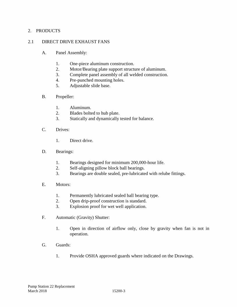
Pump Station 22 Replacement
March 2018 15200-3
2. PRODUCTS
2.1 DIRECT DRIVE EXHAUST FANS
A. Panel Assembly:
1. One-piece aluminum construction.
2. Motor/Bearing plate support structure of aluminum.
3. Complete panel assembly of all welded construction.
4. Pre-punched mounting holes.
5. Adjustable slide base.
B. Propeller:
1. Aluminum.
2. Blades bolted to hub plate.
3. Statically and dynamically tested for balance.
C. Drives:
1. Direct drive.
D. Bearings:
1. Bearings designed for minimum 200,000-hour life.
2. Self-aligning pillow block ball bearings.
3. Bearings are double sealed, pre-lubricated with relube fittings.
E. Motors:
1. Permanently lubricated sealed ball bearing type.
2. Open drip-proof construction is standard.
3. Explosion proof for wet well application.
F. Automatic (Gravity) Shutter:
1. Open in direction of airflow only, close by gravity when fan is not in
operation.
G. Guards:
1. Provide OSHA approved guards where indicated on the Drawings.
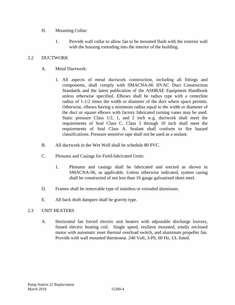
Pump Station 22 Replacement
March 2018 15200-4
H. Mounting Collar:
1. Provide wall collar to allow fan to be mounted flush with the exterior wall
with the housing extending into the interior of the building.
2.2 DUCTWORK
A. Metal Ductwork:
1. All aspects of metal ductwork construction, including all fittings and
components, shall comply with SMACNA-06 HVAC Duct Construction
Standards and the latest publication of the ASHRAE Equipment Handbook
unless otherwise specified. Elbows shall be radius type with a centerline
radius of 1-1/2 times the width or diameter of the duct where space permits.
Otherwise, elbows having a minimum radius equal to the width or diameter of
the duct or square elbows with factory fabricated turning vanes may be used.
Static pressure Class 1/2, 1, and 2 inch w.g. ductwork shall meet the
requirements of Seal Class C. Class 3 through 10 inch shall meet the
requirements of Seal Class A. Sealant shall conform to fire hazard
classifications. Pressure sensitive tape shall not be used as a sealant.
B. All ductwork in the Wet Well shall be schedule 80 PVC.
C. Plenums and Casings for Field-fabricated Units:
1. Plenums and casings shall be fabricated and erected as shown in
SMACNA-06, as applicable. Unless otherwise indicated, system casing
shall be constructed of not less than 16 gauge galvanized sheet steel.
D. Frames shall be removable type of stainless or extruded aluminum.
E. All back draft dampers shall be gravity type.
2.3 UNIT HEATERS
A. Horizontal fan forced electric unit heaters with adjustable discharge louvers,
finned electric heating coil. Single speed, resilient mounted, totally enclosed
motor with automatic reset thermal overload switch, and aluminum propeller fan.
Provide with wall mounted thermostat. 240 Volt, 3-Ph, 60 Hz, UL listed.
Pump Station 22 Replacement
March 2018 15200-5
2.4 THERMOSTATS
A. Electrical heater thermostats shall be bimetal operated mercury switch on/off type
with an adjustable universal anticipation. Thermostats shall be suitable for use on
a 24-volt control circuit.
B. Ventilation thermostats shall be bimetal actuated open contact or bellows actuated
enclosed snap switch on/off type with an adjustable universal anticipation.
Thermostats shall be suitable for use on a 120 volt, single phase control circuit.
C. All thermostats shall have a rugged corrosion resistant cover.
2.5 LOUVERS
A. Stationary drainable type fabricated from aluminum extrusion of .081” nominal
thickness with integral caulking slot. Blades shall be positioned 37 and 45 degree
angles approximately 6” on centers. Each louver shall be equipped with a framed,
removable, rear mounted screen of 3/4” x 0.51” expanded, flattened aluminum
bird screen having 80% free area with concealed vertical mullions and blade
braces. Weather-stripped frame. Anodized and lacquered finish. Sizes as
indicated on Drawings.
B. Louver finish shall be anodized aluminum, color to match exterior door finish.
C. Provide gravity type back draft dampers.
3. EXECUTION
3.1 INSTALLATION
A. Install the equipment as indicated on the Contract Drawings and in accordance
with the manufacturer's instructions.
B. Provide and connect accessories and power as required to ensure a complete
operable unit.
C. Install backer rod and caulk around exterior perimeter of louver between louver
frame and wall opening. Seal watertight. Caulking material and sealant color shall
match louver color.
3.02 MECHANICAL PERFORMANCE TESTING
A. Place the equipment into initial operation to demonstrate correct alignment,
smooth operation, freedom from noise, vibration, overheating, and all controls and
mechanical functions.
Pump Station 22 Replacement
March 2018 15200-6
3.03 EQUIPMENT ACCEPTANCE
A. Adjust, repair, modify, or replace any components, which fail to perform as
specified and rerun the tests; make final adjustments to the equipment under the
direction of the manufacturer's representative and to the satisfaction of the Owner.
END OF SECTION
Pump Station 022 Replacement
March 2018 15210-1
SECTION 15210 - DOMESTIC WATER AND WASTE PIPING
1. GENERAL
1.1 REFERENCES
The publications listed below form a part of this specification to the extent referenced. The
publications are referred to in the text by the basic designation only. The referenced
publications shall be the current effective edition.
AMERICAN SOCIETY FOR TESTING AND MATERIALS (ASTM)
ASTM B88 Seamless Copper Water Tube
AMERICAN SOCIETY OF MECHANICAL ENGINEERS (ASME)
ASME B1.20.1 Pipe Threads, General Purpose (Inch)
ASME B16.18 Cast Copper Alloy Solder Joint Pressure Fittings
AMERICAN WATER WORKS ASSOCIATION (AWWA)
AWWA C800 Underground Service Line Valves and Fittings
1.2 SUBMITTALS
Submit the following in accordance with Section 01330, "Submittal Procedures."
SD-03 Product Data
Pipe and fittings
Valves
Reduced Pressure Zone (RPZ) Backflow Preventer
Yard Hydrant
SD-07 Certificates
Submit each manufacturer's certification attesting that the pipe, pipe fittings, pipe
coupling and adapters, hose bibbs, vacuum breakers and valves meet or exceed
specification requirements.
Pump Station 022 Replacement
March 2018 15210-2
1.3 WATER CONNECTION
Contractor shall install water service connections as indicated on the drawings up to the
meter box.
2. PRODUCTS
2.1 MATERIALS
All materials, unless otherwise specified, shall be new and of the best quality of their
respective kinds, and shall conform to the requirements and ordinances of local and
insurance authorities having jurisdiction.
2.2 EXTERIOR PIPE, FITTINGS, VALVES, AND APPURTENANCES
Comply with local building code requirements. ASTM B88. Type "K" soft copper.
2.3 PIPE
ASTM B88. Hard temper Type "K". Provide dielectric fittings between steel and copper.
2.3.1 Fittings
ASME B16.18. Solder type wrought copper - 95 -5 solder.
2.3.2 Drain Waste and Vent Piping
ASTM D1785, Schedule 40 with fittings conforming to ASTM D2466.
2.4 GATE VALVES
Bronze solder end, solid wedge, rising stem, 300 lb. w.o.g. non-shock. However, use brass
valves only on all copper pipe.
2.5 UNIONS
Unions in copper pipe shall be seat fittings with bronze seats designed for a working pressure
of 125 psig.
2.6 CHECK VALVES
Threaded and solder joint check valves for use with copper water piping. Horizontal swing
check type. Bronze body, renewable bronze disc. 200 psi working pressure.
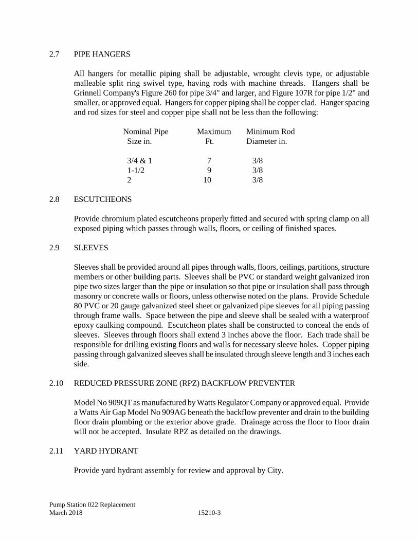
Pump Station 022 Replacement
March 2018 15210-3
2.7 PIPE HANGERS
All hangers for metallic piping shall be adjustable, wrought clevis type, or adjustable
malleable split ring swivel type, having rods with machine threads. Hangers shall be
Grinnell Company's Figure 260 for pipe 3/4" and larger, and Figure 107R for pipe 1/2" and
smaller, or approved equal. Hangers for copper piping shall be copper clad. Hanger spacing
and rod sizes for steel and copper pipe shall not be less than the following:
Nominal Pipe Maximum Minimum Rod
Size in. Ft. Diameter in.
3/4 & 1 7 3/8
1-1/2 9 3/8
2 10 3/8
2.8 ESCUTCHEONS
Provide chromium plated escutcheons properly fitted and secured with spring clamp on all
exposed piping which passes through walls, floors, or ceiling of finished spaces.
2.9 SLEEVES
Sleeves shall be provided around all pipes through walls, floors, ceilings, partitions, structure
members or other building parts. Sleeves shall be PVC or standard weight galvanized iron
pipe two sizes larger than the pipe or insulation so that pipe or insulation shall pass through
masonry or concrete walls or floors, unless otherwise noted on the plans. Provide Schedule
80 PVC or 20 gauge galvanized steel sheet or galvanized pipe sleeves for all piping passing
through frame walls. Space between the pipe and sleeve shall be sealed with a waterproof
epoxy caulking compound. Escutcheon plates shall be constructed to conceal the ends of
sleeves. Sleeves through floors shall extend 3 inches above the floor. Each trade shall be
responsible for drilling existing floors and walls for necessary sleeve holes. Copper piping
passing through galvanized sleeves shall be insulated through sleeve length and 3 inches each
side.
2.10 REDUCED PRESSURE ZONE (RPZ) BACKFLOW PREVENTER
Model No 909QT as manufactured by Watts Regulator Company or approved equal. Provide
a Watts Air Gap Model No 909AG beneath the backflow preventer and drain to the building
floor drain plumbing or the exterior above grade. Drainage across the floor to floor drain
will not be accepted. Insulate RPZ as detailed on the drawings.
2.11 YARD HYDRANT
Provide yard hydrant assembly for review and approval by City.
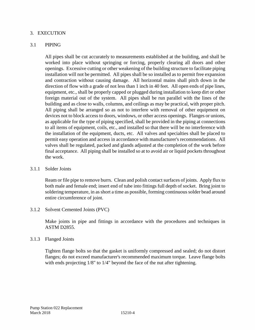
Pump Station 022 Replacement
March 2018 15210-4
3. EXECUTION
3.1 PIPING
All pipes shall be cut accurately to measurements established at the building, and shall be
worked into place without springing or forcing, properly clearing all doors and other
openings. Excessive cutting or other weakening of the building structure to facilitate piping
installation will not be permitted. All pipes shall be so installed as to permit free expansion
and contraction without causing damage. All horizontal mains shall pitch down in the
direction of flow with a grade of not less than 1 inch in 40 feet. All open ends of pipe lines,
equipment, etc., shall be properly capped or plugged during installation to keep dirt or other
foreign material out of the system. All pipes shall be run parallel with the lines of the
building and as close to walls, columns, and ceilings as may be practical, with proper pitch.
All piping shall be arranged so as not to interfere with removal of other equipment on
devices not to block access to doors, windows, or other access openings. Flanges or unions,
as applicable for the type of piping specified, shall be provided in the piping at connections
to all items of equipment, coils, etc., and installed so that there will be no interference with
the installation of the equipment, ducts, etc. All valves and specialties shall be placed to
permit easy operation and access in accordance with manufacturer's recommendations. All
valves shall be regulated, packed and glands adjusted at the completion of the work before
final acceptance. All piping shall be installed so at to avoid air or liquid pockets throughout
the work.
3.1.1 Solder Joints
Ream or file pipe to remove burrs. Clean and polish contact surfaces of joints. Apply flux to
both male and female end; insert end of tube into fittings full depth of socket. Bring joint to
soldering temperature, in as short a time as possible, forming continuous solder bead around
entire circumference of joint.
3.1.2 Solvent Cemented Joints (PVC)
Make joints in pipe and fittings in accordance with the procedures and techniques in
ASTM D2855.
3.1.3 Flanged Joints
Tighten flange bolts so that the gasket is uniformly compressed and sealed; do not distort
flanges; do not exceed manufacturer's recommended maximum torque. Leave flange bolts
with ends projecting 1/8" to 1/4" beyond the face of the nut after tightening.
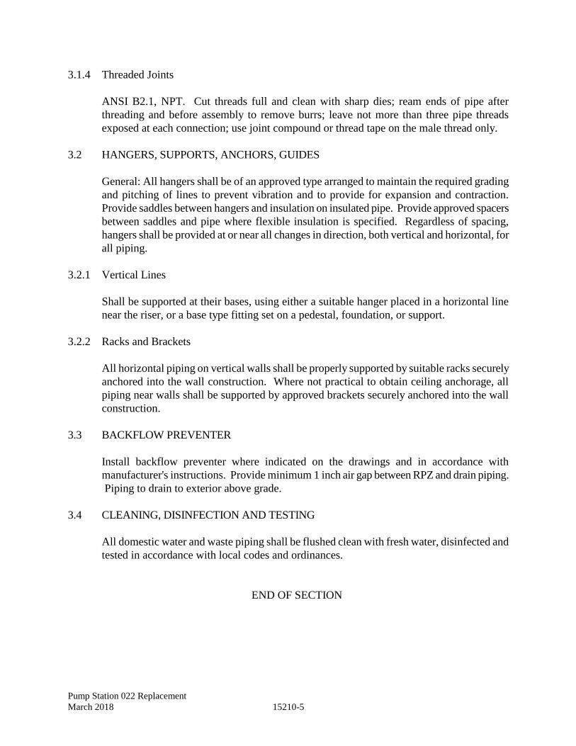
Pump Station 022 Replacement
March 2018 15210-5
3.1.4 Threaded Joints
ANSI B2.1, NPT. Cut threads full and clean with sharp dies; ream ends of pipe after
threading and before assembly to remove burrs; leave not more than three pipe threads
exposed at each connection; use joint compound or thread tape on the male thread only.
3.2 HANGERS, SUPPORTS, ANCHORS, GUIDES
General: All hangers shall be of an approved type arranged to maintain the required grading
and pitching of lines to prevent vibration and to provide for expansion and contraction.
Provide saddles between hangers and insulation on insulated pipe. Provide approved spacers
between saddles and pipe where flexible insulation is specified. Regardless of spacing,
hangers shall be provided at or near all changes in direction, both vertical and horizontal, for
all piping.
3.2.1 Vertical Lines
Shall be supported at their bases, using either a suitable hanger placed in a horizontal line
near the riser, or a base type fitting set on a pedestal, foundation, or support.
3.2.2 Racks and Brackets
All horizontal piping on vertical walls shall be properly supported by suitable racks securely
anchored into the wall construction. Where not practical to obtain ceiling anchorage, all
piping near walls shall be supported by approved brackets securely anchored into the wall
construction.
3.3 BACKFLOW PREVENTER
Install backflow preventer where indicated on the drawings and in accordance with
manufacturer's instructions. Provide minimum 1 inch air gap between RPZ and drain piping.
Piping to drain to exterior above grade.
3.4 CLEANING, DISINFECTION AND TESTING
All domestic water and waste piping shall be flushed clean with fresh water, disinfected and
tested in accordance with local codes and ordinances.
END OF SECTION

Pump Station 022 Replacement
March 2018 15210-6
This Page Intentionally Left Blank

Pump Station 022 Replacement
March 2018 16010-1
SECTION 16010 - ELECTRICAL BASIC REQUIREMENTS
1. GENERAL
1.1 SUMMARY
A. Scope: Extent of electrical work covered by this Section is specified in all other
sections of Division 16, the drawings, schedules and by requirements of this Section.
B. Refer to the Contract and Division 16 sections for additional electrical requirements
including:
1. Summary of the work.
2. Project Coordination.
3. Definitions and Standards.
4. Submittals.
5. Schedules and Reports.
6. Temporary Facilities.
7. Products.
8. Testing and Final Acceptance.
9. Project Closeout.
C. The word provide, as used hereinafter, shall be defined to mean the furnishing of all
labor, materials, equipment and services necessary for the work described.
1.2 QUALITY ASSURANCE
A. Labels and Listings: Materials, appliances and equipment provided shall meet the
requirements of the Underwriters Laboratories, Inc. (UL), Electrical Testing
Laboratories (ETL) and other standards organizations.
B. National Fire Protection Association (NFPA): All work provided under this Contract
shall meet the requirements of NFPA 70, "National Electrical Code", latest edition.
C. Current Models:
1. Manufactured items furnished shall be the current, cataloged product of the
manufacturer. No more than 12 months old.
2. Replacement parts shall be available.
D. There shall be a permanent service organization maintained or trained by the
manufacturer to provide satisfactory service.
E. Experience: Manufactured items shall have been installed and used without
modifications, renovation, or repair, on other projects for not less than three (3) years
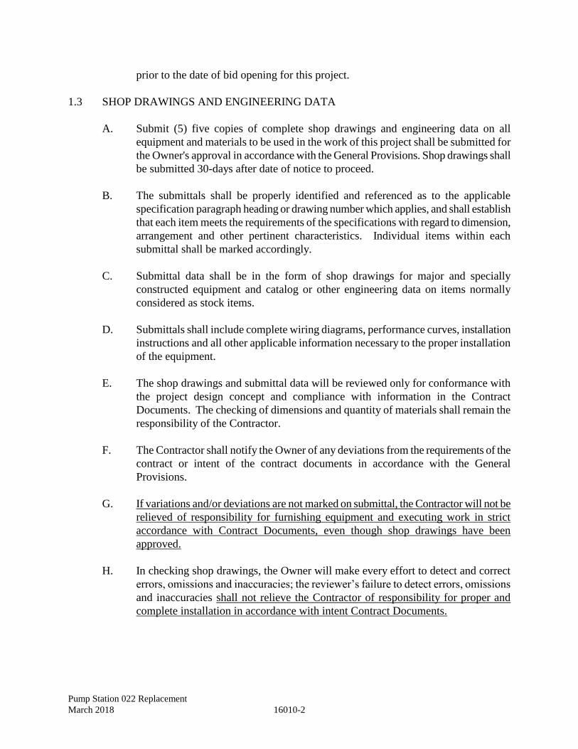
Pump Station 022 Replacement
March 2018 16010-2
prior to the date of bid opening for this project.
1.3 SHOP DRAWINGS AND ENGINEERING DATA
A. Submit (5) five copies of complete shop drawings and engineering data on all
equipment and materials to be used in the work of this project shall be submitted for
the Owner's approval in accordance with the General Provisions. Shop drawings shall
be submitted 30-days after date of notice to proceed.
B. The submittals shall be properly identified and referenced as to the applicable
specification paragraph heading or drawing number which applies, and shall establish
that each item meets the requirements of the specifications with regard to dimension,
arrangement and other pertinent characteristics. Individual items within each
submittal shall be marked accordingly.
C. Submittal data shall be in the form of shop drawings for major and specially
constructed equipment and catalog or other engineering data on items normally
considered as stock items.
D. Submittals shall include complete wiring diagrams, performance curves, installation
instructions and all other applicable information necessary to the proper installation
of the equipment.
E. The shop drawings and submittal data will be reviewed only for conformance with
the project design concept and compliance with information in the Contract
Documents. The checking of dimensions and quantity of materials shall remain the
responsibility of the Contractor.
F. The Contractor shall notify the Owner of any deviations from the requirements of the
contract or intent of the contract documents in accordance with the General
Provisions.
G. If variations and/or deviations are not marked on submittal, the Contractor will not be
relieved of responsibility for furnishing equipment and executing work in strict
accordance with Contract Documents, even though shop drawings have been
approved.
H. In checking shop drawings, the Owner will make every effort to detect and correct
errors, omissions and inaccuracies; the reviewer’s failure to detect errors, omissions
and inaccuracies shall not relieve the Contractor of responsibility for proper and
complete installation in accordance with intent Contract Documents.

Pump Station 022 Replacement
March 2018 16010-3
I. As a minimum the following shall be submitted for approval:
1. Panelboards and Circuit Breakers,
2. Light Fixtures, Lenses, and Mounting Equipment,
3. Wiring Devices and Plates,
4. Safety Switches,
5. Pump Control Panel
6. Control and Monitoring Equipment
7. Manual Transfer Switches
8. RTU
9. Variable Frequency Drives
10. Programmable Logic Controller
11. Name Plates
12. Others as required by the respective specification section
J. Submit shop drawings 30-days after date of notice to proceed.
1.4 STORAGE AND HANDLING
A. Storage: Materials stored at the project site, which become soiled with construction
dirt, concrete, paint, etc. shall be washed, cleaned and dried or removed from the
project site and replaced with new. Do not install soiled material.
B. Cleaning: Clean and wipe the interior of conduit, pullboxes, and panelboard
backboxes, soiled by masonry trades, before proceeding with wiring.
C. Do not install damaged, broken or marred material or products, replace with new,
unless otherwise approved by the Owner in writing.
1.5 LABELS AND NAMEPLATES
A. Manufacturer's Nameplates: Nameplates on manufactured items shall be aluminum
or type 304 stainless steel sheet, not less than 20 USG, secured to the manufactured
item, with nameplate data engraved or punched to form a non-erasable record of
equipment data.
B. Field Installation: Field-installed nameplates shall be as per Section 16195,
"Electrical Identification".
1.6 TEMPORARY FACILITIES
A. The Contractor is responsible for all temporary facilities as required during
construction as set forth in Section 107 of the General Provisions.
Pump Station 022 Replacement
March 2018 16010-4
1.7 SIZING
A. Capacity: Provide equipment and material of sizes, capacities, horsepowers, power
ratings and dimensions indicated on the drawings, in the schedules and as specified.
B. Fit and Clearance: Equipment and material of greater or larger power dimensions,
capacity and ratings may be furnished provided such proposed equipment is approved
in writing and feeders, circuit breakers, conduit, motors, bases and equipment spaces
are increased by the Contractor at no additional cost, to the contract cost.
1.8 COORDINATION
A. Coordinate electrical work with that of other trades so that:
1. Interference between general construction, mechanical, electrical, structural
and other specialty trades is avoided.
2. Maintain clearances and advise other trades of clearance requirements for
operation, repair, removal, and testing of electrical equipment.
3. All electrical materials and equipment shall be kept as close as possible to
ceiling, walls, and columns to occupy the minimum amount of space.
4. Furnish and install all offsets, fittings, and similar items necessary to
accomplish the requirements of coordination, without additional expense.
5. Coordinate electrical requirements for equipment provided by Mechanical
Contractors to assure proper compatibility with equipment provided.
B. Other divisions of these specifications and drawings shall be carefully examined to
determine the requirements of the project as a whole and to determine
interconnecting points between the various trades. All such interconnections shall be
properly made and with due regard for correct arrangements suited to the equipment
or material concerned.
C. Provide power wiring and final power connections to equipment installed by other
trades, which requires electrical power. Other trades will supply power
characteristics and roughing-in data to ensure the proper power wiring of their
equipment.
D. Provide disconnect switches for equipment of other trades when required, and
specifically for motors, which are out of sight of their controllers, unless switches are
provided integrally mounted on the equipment.
Pump Station 022 Replacement
March 2018 16010-5
E. All control wiring for other trades will be performed under another division of these
specifications unless otherwise noted. Control wiring shall be considered as that
wiring, low or high voltage, which is required for devices such as pushbuttons,
thermostats, valves, control switches for starters, interlocking of starters, and any
other wiring required by similar control devices and is not included in this division,
except as noted.
1.9 CODES, PERMITS AND FEES
All work performed and all material installed under this Division shall conform to the latest
editions of BOCA including the latest edition of NFPA No. 70 (NEC) and other applicable
standards of the NFPA and all laws, ordinances and all governing authorities. The
Contractor shall procure and pay for all licenses, permits, fees, etc., necessary to install and
complete the work.
1.10 MANUFACTURER'S RECOMMENDATIONS
Where installation procedures or any part thereof are required to be in accordance with
manufacturer's recommendations, furnish printed copies of the recommendations prior to
installation. Installation of the item shall not proceed until recommendations are received.
Failure to furnish recommendations shall be cause for rejection of the equipment or material.
2. PRODUCTS
2.1 MATERIALS AND WORKMANSHIP
A. It is the intent of these specifications to establish quality standards for all material
and equipment incorporated in the work of this division. All materials and
equipment installed hereunder shall be new and shall be the best of each respective
kind and type. Proper care shall be exercised in handling all materials and equipment
herein specified so as not to injure or mar finished surfaces and to insure that the
work is acceptable in every respect upon completion.
B. The installation shall be as indicated on the drawings and in accordance with the
manufacturer's recommendations as approved by the Owner. The installation shall be
accomplished by workmen skilled in their respective trades.
C. No products shall contain asbestos or other hazardous substances.
D. As far as practicable, use a common manufacturer for similar products. These
products are to be selected to maximize component interchange ability.
E. Provide all necessary accessories and appurtenances required for a complete
installation even if not called out specifically on the drawings or indicated herein.
Pump Station 022 Replacement
March 2018 16010-6
3. EXECUTION
3.1 INTENT OF DRAWINGS
A. The drawings are diagrammatic, intending to show general runs and locations of
equipment and specialties, and not necessarily showing all required offsets, etc.
Carefully study the various runs of conduit and make such adjustments in exact
routing as may be necessary to fit conduits into space available and to avoid conflict
with other trades.
B. Arrange equipment substantially as shown on the Drawings. Make deviations only
where necessary to avoid interference. Check equipment size against available space
prior to shipment to avoid interference.
3.2 PAINTING AND FINISHING
Damage and Touch-Up: Repair all marred or damaged factory painted finishes with
materials and procedures to match original factory finish and as specified in Section 09910.
3.3 WIRING FOR SPECIAL EQUIPMENT
Provide all wiring, outlets, and connections for connecting all equipment. All outlets and
connections shall be verified and coordinated with equipment manufacturer's roughing-in
drawings before installation and all adjustments shall be made to satisfy the manufacturer's
requirements. All equipment shall be connected and ready for use.
3.4 MOTOR, EQUIPMENT AND APPARATUS CONNECTIONS
A. Provide all necessary electric power connections and disconnect switches as required
for all equipment requiring such connections. This Contractor shall coordinate his
work with roughing-in drawings provided by manufacturer or Party furnishing
equipment.
B. All motors shall conform to the latest applicable NEMA standards for type, size, and
duty, as specifically applied. All motors shall be suitable for operation on 60 cycle
a.c. and with voltage and other characteristics as specified in other Divisions of these
Specifications.
C. Motor controller furnished shall conform to the latest applicable NEMA standards for
type, size, and duty as specifically applied. Magnetic controllers shall provide
thermal overload protection in each line not to exceed 125 percent of the motor full
load current rating and shall be provided with a manual reset type pushbutton on
outside of housing. Magnetic starters shall be equipped with 115 volt holding coils,
control transformers having 115 volt fused secondaries and necessary number of
auxiliary contacts.
Pump Station 022 Replacement
March 2018 16010-7
D. Magnetic controllers shall provide under voltage protection when used with
momentary contact control devices and under voltage released when used with
maintained-contact control devices. Manual type controllers shall provide thermal
overload protection not to exceed values listed above, plus the actual current drawn
by auxiliary controls and shall be approved for group fusing when more than one
motor is served by the same branch circuit.
E. Provide disconnect switches as required conforming to the latest applicable NEMA
standards for Type HD safety switches enclosed in NEMA Type 1 or 3R enclosures
or as indicated and as required. Where fusible switches are required, they shall be
equipped with dual element fuses. Any motor out of sight of its controller and any
controller out of sight of its branch circuit breaker shall be provided with
disconnecting switch in accordance with Article 430 of NEC.
F. Install control and alarm wiring for all equipment, mechanical and electrical, in
accordance with Division 16 Specification Sections. Before installing control
circuits, ensure that controls and wiring diagrams are in accordance with those
furnished with the equipment. Make any changes required due to different
equipment, more up-to-date controls or safety devices, so that the equipment operates
as required. Control voltage shall not exceed 120 volts unless indicated otherwise on
the Drawings.
G. When equipment is supplied with electrical requirements other than those specified
or shown on the Drawings, associated electrical devices and circuitry of the correct
sizes and ratings shall be provided.
3.5 CUTTING AND PATCHING
A. Cutting: Provide cutting, channeling, chasing, and drilling of floors, walls, partitions,
ceilings and other surfaces necessary for installation of electrical work. All cutting
shall be performed by skilled mechanics of the trades involved.
B. Patching: Repair cut surfaces to match adjacent surfaces.
3.6 CLOSING OF OPENINGS
A. Firestopping: Unused slots, sleeves and other penetrations in floors, walls or other
general construction shall be closed and sealed with an approved firestopping
material per UL 1479.
B. Conduit: The annulus between exposed conduit and walls or floors in finished
spaces shall be filled, sealed, and painted to match adjacent surfaces.
C. Future Slots: Identify unused sleeves and slots for future use by permanently
anchored brass nameplates identifying size and purpose of the covered slot.
Pump Station 022 Replacement
March 2018 16010-8
3.7 SYSTEM TEST
A. Prior to final site visitation, field testing and acceptance testing, the Contractor shall
conduct an operating test of the complete electrical system. System shall test free
from grounds, shorts and other faults. All connections as possible shall be
thoroughly checked for positive mechanical and electrical connection and continuity.
All equipment shall be demonstrated to operate in accordance with the requirements
set forth in these specifications and shown on the drawings.
B. Perform all tests in the presence of the Owner or his duly authorized representative.
The Contractor shall furnish all personnel and test instruments for use in the test.
3.8 OPERATION AND MAINTENANCE MANUALS
A. The Contractor shall provide the Owner with a copy of the operation and
maintenance manuals for all electrical equipment 30 days prior to project closeout for
approval. After approval from the Owner, the Contractor shall deliver five corrected
copies bound in a loose leaf binder to the owner in accordance with Section 01781.
In addition to the requirements of Section 01781, the binder shall be labeled and
indexed as follows:
B. The material included in the operation and maintenance manual tabs shall have
included:
1. Approved shop drawings with model numbers including:
a. Light fixtures
b. Receptacles
c. Switches
d. Panelboards
e. Variable Frequency Drives
f. Programmable Logic Controller
g. Disconnect Switches
h. Motor Starters
i. Wires and cables
j. Conduit, raceways, and pathways
k. All Test Reports
l. All warranty information
C. Separate operation and maintenance manuals including shop drawings and diagrams
to be included shall be as follows:
1. Pump Control Panel
Pump Station 022 Replacement
March 2018 16010-9
3.9 RECORD DRAWINGS (AS-BUILTS)
A. The Contractor shall maintain and deliver Record Drawings in accordance with the
requirements of the General Provisions.
B. The Contractor shall maintain at the job site one set of blue line or black line prints of
the drawings approved by the Owner. The Contractor shall record thereon all changes
in the location, sizing, and arrangement that may be made for any reason in the work
during the course of construction including Addenda and Change Orders work so as
to reflect the installation “as-built”. Upon completion of the project, “as-built”
drawings shall be prepared and submitted to the Owner in accordance with the
requirements of the General Provisions.
3.10 FINAL SITE VISITATION
When the work on the entire project has been completed and is ready for final review, a visit
will be made by the Owner or his duly authorized representative, at which time the
Contractor shall demonstrate that the requirements of the Contract have been carried out and
that the system has been adjusted and operates in accordance therewith.
3.11 GUARANTEE
Contractor shall warrant and guarantee all work in accordance with the General Provisions
and as may be further specified herein.
END OF SECTION

Pump Station 022 Replacement
March 2018 16010-10
This Page Intentionally Left Blank
Pump Station 022 Replacement
March 2018 16020-1
SECTION 16020 - UTILITY SERVICE AND SERVICE ENTRANCE
1. GENERAL
1.1 SCOPE
A. Work required under this heading covers the equipment necessary to provide
power for all loads for a complete working installation.
1.2 ELECTRICAL SERVICE
A. Electrical service shall be as shown on the drawings and as specified herein.
B. All service work shall be coordinated with the local Power Company and National
Electrical Code.
C. Electrical service shall be 120/240V, hi-leg delta, three phase, 4-wire.
D. Verify complete electrical service installation with Power Company before start
up.
E. If required, the Contractor shall coordinate with Dominion Energy regarding the
location of the pad mounted transformer and prefabricated bases. The Contractor
shall provide finish grade for power company work.
F. Make application with electrical utility company for electric service in a manner
to permit utility company to provide service prior to completion of work under
this contract.
G. Complete and file all forms required by the electric utility company in connection
with application for electric service. Pay for all required licenses, permits, fees,
etc. necessary to obtain electric service. Power Company charges required to
perform work to provide service to the facility will be paid directly by the Owner
and will not be part of this contract.
H. Provide underground raceways and conductors from utility company transformer
to main service equipment.
I. Install sealable meter compartment furnished by Dominion Energy.
J. Furnish and install interconnecting raceway between metering transformers and
revenue meter. Install all equipment in conformity with utility company’s
requirements.
Pump Station 022 Replacement
March 2018 16020-2
2. PRODUCTS
Not applicable.
3. EXECUTION
Not applicable.
END OF SECTION
Pump Station 022 Replacement
March 2018 16035-1
SECTION 16035 - ELECTRICAL TESTING AND PLACING IN SERVICE
1. GENERAL
1.1 WORK INCLUDED
A. The Contractor shall perform electrical testing in the presence of the Owner prior to
Initial Field Testing and Final Acceptance Testing.
B. Provide all material, equipment, labor, and technical supervision to perform and
complete the electrical acceptance test in accordance with the requirements of this
Section for equipment furnished by the Contractor. Notify Owner at least seven days
in advance of tests.
C. Perform tests on the following equipment:
1. Grounding.
2. Power cables, 600 volts and lower.
3. Rotating equipment.
4. Panelboards
5. Motor Control Center
6. As required by other specification sections
D. Perform electrical testing as required by other Divisions 16 specifications for
specific equipment including:
1. Section 11330 – Non-Clog Submersible Centrifugal Pumps and Drives
2. Section 16120 – Wire and Cables
3. Section 16135 – Wiring Devices
4. Section 16410 – Pump Control Panel
5. Section 16450 – Grounding
6. Section 16470 – Panelboards
7. Section 16842 – Motor Starters
8. Section 16690 – Variable Frequency Drives
9. Section 16900 – Remote Terminal Unit
10. Section 16920 – Programmable Logic Controller
Pump Station 022 Replacement
March 2018 16035-2
1.2 QUALITY ASSURANCE
A. Final acceptance will depend upon successful completion of specified testing.
B. Perform all tests in accordance with manufacturer's recommendations. Should
manufacturer's recommendations conflict with these specifications, notify Owner. Do
not proceed with tests until directed by the Owner.
C. Material or equipment failing tests shall be repaired or replaced at the Contractor's
expense.
D. The Contractor shall be responsible for all test and test records. Testing shall be
performed by or under the immediate supervision of the Contractor, and in the
presence of the Owner or Owner’s representative.
E. Inspect the equipment prior to energizing.
F. The Contractor shall coordinate with certified manufacturer’s representatives for
those items specified as requiring representation during start up and testing.
1.3 SUBMITTALS
Submit the following:
A. Electrical Testing Reports
Results of testing shall be fully documented including dates of testing, equipment
utilized, person performing tests, tests made, comparative acceptable test results and
reference standards, actual test results, corrections made and results of retesting for
each piece of equipment or component tested. Submit test results neatly bound and
organized in three ring binders with divider pages separating each set of tests, a
complete table of contents, and listing of testing equipment including calibration
certifications.
B. Certificates
The contractor shall provide a written certification that the electrical testing was
completed successfully, all deficiencies corrected, and initially deficient equipment
and or components were retested successfully.
C. The Contractor shall provide the Owner with one copy of the building regulation
certificate of inspections, including any failing inspections.
Pump Station 022 Replacement
March 2018 16035-3
2. PRODUCTS
2.1 TESTING DEVICES
The Contractor shall employ all testing devices and personnel trained in their use, required
for testing as specified herein.
3. EXECUTION
3.1 TESTING AND MEASUREMENTS
A. Measure and record voltages, at all service equipment, manual transfer switch,
panelboards motor control panel.
B. Each power and convenience outlet shall be subjected to tests for polarity, open
wiring, and continuous ground.
3.2 GROUND SYSTEM TESTING
Upon completion of installation of the electrical grounding and bonding systems, test the
existing ground resistance with a ground resistance tester. Where tests show resistance-to-
ground is over 10 ohms, take appropriate action to reduce the resistance to 10 ohms, or less,
by driving additional ground rods. Then retest to demonstrate compliance.
3.3 CABLE CONTINUITY AND PHASE IDENTIFICATION
Check cable continuity and phase identification.
3.4 FEEDER INSULATION RESISTANCE TESTING
A. All current carrying phase conductors and neutrals shall be tested as installed, and
before connections are made, for insulation resistance and accidental grounds. This
shall be done with a 500 volt megger. The procedures listed below shall be followed:
B. Minimum readings shall be one million (1,000,000) or more ohms between
conductors and between conductor and the grounding conductor.
C. After all fixtures, devices and equipment are installed and all connections are
installed and all connections completed to each panel, the contractor shall disconnect
the neutral feeder conductor from the neutral bar and take a megger reading between
the neutral bar and the grounded enclosure. If this reading is less than 250,000 ohms,
the Contractor shall disconnect the branch circuit neutral wires from this neutral bar.
The Contractor shall then test each one separately to the panel until the low readings
are found. The Contractor shall correct troubles, reconnect, and retest until at least
Pump Station 022 Replacement
March 2018 16035-4
250,000 ohms from the neutral bar the grounded panel can be achieved with only the
neutral feeder disconnected.
D. The Contractor shall send a letter to the Owner certifying that the above has been
done and tabulating the megger readings for each panel. This shall be submitted at
least four (4) days prior to final inspection.
E. At final inspection, the Contractor shall furnish a megger and show the Owner that
the panels comply with the above requirements. He shall also furnish a hook-on type
ammeter and voltage readings as directed by the representatives.
3.5 DOCUMENTATION
A. All tests specified shall be completely documented indicating time of day, date,
temperature and all pertinent test information.
B. All required documentation of readings indicated above shall be submitted to the
Owner prior to, and as one of the pre-requisites for, Initial Field Testing and Final
Acceptance Testing.
END OF SECTION
Pump Station 022 Replacement
March 2018 16110-1
SECTION 16110 - RACEWAYS
1. GENERAL
1.1 SUMMARY
A. Scope: Extent of raceway work is indicated on the drawings, by the requirements of
this Section, and Section 16010, "Electrical Basic Requirements".
B. Types: Types of raceways in this Section include the following:
1. Flexible steel conduit.
2. Rigid Galvanized Steel Conduit
3. Liquid-tight flexible metal conduit.
4. Rigid metal conduit.
5. Wireway.
6. Plastic / PVC
1.2 QUALITY ASSURANCE
A. National Fire Protection Association (NFPA): Comply with NFPA 70, "National
Electrical Code", for application, size, location, and installation of each type of
raceway used.
B. Provide products specified in conformance with the indicated standards.
1.3 SUBMITTALS
Product Data: Submit manufacturer's data for each type of raceway. Submit shop drawings 30-
days after date of notice to proceed.
1.4 HAZARDOUS LOCATIONS
Raceway in designated hazardous or explosion proof locations shall conform to NFPA 70
requirements for installation.
2. PRODUCTS
2.1 CONDUIT REQUIREMENTS
A. Each length of conduit shall bear the manufacturer’s stamp and UL label.
Pump Station 022 Replacement
March 2018 16110-2
2.2 METAL CONDUIT AND TUBING
A. Rigid conduit shall be mild steel piping, hot-dipped, zinc-coated or sherardized, and
of sufficient weight and toughness to withstand cracking and peeling during bending.
Each piece of rigid conduit to be straight, free from blisters and defects, cut square
and taper reamed, finished in 10’ lengths and threaded at each end. Couplings shall
be supplied at one end and a protective sleeve for the other end. All threads to be
clearly cut. Each length to bear UL label.
B. PVC coated rigid steel conduit shall have a permanent plastic coating factory applied
to a minimum thickness of 40 mils and a urethane internal coating. PVC coated shall
be Plasti-Bond Red as manufactured by Robroy Industries or approved equal.
C. Flexible metal conduit shall be galvanized, continuous spiral, single strip type and
shall be used in accordance with NEC Article 350. In areas subject to moisture, or
where indicated, liquid tight flexible conduit shall be used in accordance with NEC
Article 351. Fittings shall be standard UL approved with ground connector.
Watertight connectors shall be used with liquid tight flexible conduit.
2.3 NONMETALLIC CONDUITS AND RACEWAYS
A. Electrical plastic conduit, PVC Type, shall conform to NEMA TC 2, “Conduit (EPC-
40 and EPC-80)”.
B. Provide in conformance with ANSI 870, “Wireways, Auxiliary Gutters, and
Associated Fittings”.
2.4 METAL AND PLASTIC CONDUIT AND RACEWAY FITTINGS
A. Fittings for conduit and outlet boxes shall conform to UL 514B, “Fittings for Conduit
and Outlet Boxes”.
B. PVC fittings for use with rigid PVC conduit and tubing shall conform to NEMA TC
3, “PVC Fittings for Use with Rigid PVC Conduit and Tubing”.
C. Nonmetallic conduits and raceways.
D. Raceway seals.
3. EXECUTION
3.1 MINIMUM SIZE
Size conduit and raceway in accordance with NFPA 70 unless otherwise specified or shown
on the drawings. Minimum size 3/4-inch for interior work and 1-inch for exterior work.
Pump Station 022 Replacement
March 2018 16110-3
3.2 EQUIPMENT GROUND CONDUCTOR
Raceways sizes shall be adequate to include the circuit conductors, an equipment ground
conductor, and a neutral conductor in accordance with percentage of fill requirements by
NFPA 70. Size all conduits supplying motors and associated control equipment to include
grounding conductor sized per NFPA 70 whether or not shown on the drawings or specified.
3.3 CONDUIT
A. All exterior conduit shall be PVC coated rigid galvanized steel conduit.
B. All exterior conduit installed below grade shall be Schedule 80 PVC.
C. All conduit installed in the wet well shall be Schedule 80 PVC.
D. All conduit in slab, transitions, through slab, and penetrations through walls and
floors shall be Schedule 80 PVC.
E. All interior conduit shall be Schedule 80 PVC.
F. Conduit for power and control circuits shall be color coded. Conduit for power
circuits shall be red; conduits for control circuits shall be orange
3.4 LIQUID-TIGHT FLEXIBLE METAL CONDUIT
A. Sizes 1-1/4-inch and smaller, provide with continuous copper bonding conductor
wound spirally between convolutions.
B. Sizes 1-1/2-inch and larger, provide with an internal grounding conductor and
grounding bushings.
C. Provide liquid-tight flexible metal conduits for connections to motors and other
electrical equipment when it is subject to movement, vibration, misalignment,
cramped quarters, or where noise transmission is to be eliminated or reduced.
3.5 WIREWAYS, AUXILIARY GUTTERS
A. May be used to facilitate installation and future changes in wiring between
panelboards, safety switches in close proximity to each other on same or adjacent
walls or in same electrical equipment room or area.
B. Provide weatherproof enclosure where outdoors or subject to moisture and similar
elements.
Pump Station 022 Replacement
March 2018 16110-4
C. Use where shown on drawings or specified.
D. Shall be completely accessible.
3.6 RACEWAY FITTINGS, COUPLINGS AND CONNECTORS
A. Use fittings listed and approved for specific conduit or raceway system used.
B. For threaded rigid steel conduit do not use threadless or compression type fittings.
C. Bushing and connector shall be insulated type, which maintain continuity of conduit
grounding system. Insulating material shall be molded or locked into metallic body of
the fitting. Bushing made entirely of nonmetallic material will not be allowed.
Where concentric, eccentric or over- sized knockouts are encountered, a grounding-
type insulated bushing shall be provided.
D. Liquid-tight flexible metal conduit shall incorporate a threaded grounding cone, a
steel, nylon or equal plastic compression ring and a gland for tightening. Fitting shall
be steel or malleable iron with insulated throat, with male thread and locknut or male
bushing with or without "O" ring seal.
E. Provide expansion fittings for all rigidly fastened conduits spanning a building
expansion joint and if not otherwise provided, for all runs 1-1/2-inch or larger,
exceeding 150 feet in length. Fittings shall be hot-dipped galvanized malleable iron
with a packing ring to prevent entrance of water, a pressure ring, a grounding ring,
and a separate external copper bonding jumper.
F. Inferior material such as "pot metal" shall not be used for any type of fitting.
G. All locknuts shall be the bonding type with sharp edges for digging into the metal
wall of an enclosure.
H. The use of "LB's" shall be limited where possible. Where necessary to use "LB's"
sized above 2-inch, mogul units shall be installed.
Pump Station 022 Replacement
March 2018 16110-5
3.7 GENERAL
A. Run conduits exposed. Conduit shall be supported at intervals of not more than 8'.
Run exposed conduit parallel or perpendicular to walls, structural members, or
intersections of vertical planes and ceiling. Changes in direction of runs shall be
made with symmetrical bends or fittings to match conduit type. Avoid field made
bends and offsets where possible, but where necessary they shall be made with an
approved hickey or conduit bending machine. No bend shall have less than 3-1/2"
radius. No bend shall be more than 90 degrees. There shall not be more than four
right angle bends or the equivalent in one run. Conduit shall have clean, sharp
threads carefully reamed ends and tight joints. Crushed or deformed conduits shall
not be installed. Avoid trapped conduits where possible. Take care to prevent the
lodgment of dirt or trash in conduit, boxes, fittings and equipment during the course
of construction. Clogged conduits shall be entirely cleared of obstructions or shall be
replaced. Fasten conduit to all sheet metal boxes and cabinets with two locknuts
where required by NEC, where insulating bushings are used, and where bushings
cannot be brought into firm contact with the box; otherwise a single locknut and
bushing are acceptable.
B. Support conduits by pipe straps, wall brackets, strap hangers, or ceiling trapeze,
fastened by toggle bolts on hollow masonry units and bolts and expansion shields on
concrete or brick. Unless otherwise indicated, nail type nylon anchors provided with
lock washers and nuts or threaded steel studs driven in by powder charge and
provided with lock washers and nuts are acceptable in lieu of expansion shields or
machine screws. Wires twisted around structural members as a support for conduits
will not be acceptable. Wooden plugs inserted in concrete on masonry are not
acceptable as a base for conduit fastening, nor shall conduit or pipe straps be welded
to steel structures.
C. All floor penetrations through floor slabs for the transition from one floor to the
next shall be provided with PVC sleeves.
3.8 ADJUSTING AND CLEANING
A. Upon completion of installation of raceways, inspect interiors of raceways at all
outlet, junction, and pull boxes, remove burrs and obstructions.
B. Run a swab or mandrel to remove dirt and blockages. Raceways, which are
deformed and prevent the passage of a mandrel, shall be replaced.
C. Remove dirt and construction debris from outlet, junction, and pull boxes.
END OF SECTION

Pump Station 022 Replacement
March 2018 16110-6
This Page Intentionally Left Blank
Pump Station 022 Replacement
March 2018 16120-1
SECTION 16120 - WIRE AND CABLES
1. GENERAL
1.1 SUMMARY
A. Scope: Extent of electrical wire and cable work is indicated on the drawings and
schedules, by the requirements of this Section, and Section 16010, "Electrical Basic
Requirements" and Section 16035, “Electrical Testing and Placing in Service”.
B. Types: Types of electrical wire, cable, and connectors specified in this Section
include the following:
1. Copper conductors.
2. Tap type connectors.
3. Split-bolt connectors.
4. Wire nut connectors.
1.2 QUALITY ASSURANCE
A. American Society for Testing and Materials (ASTM): Comply with requirements of
the following:
1. B 1 Standard Specification for Hard-Drawn Copper Wire
2. B 8 Standard Specification for Concentric-Lay-Stranded Copper Conductors,
Hard, MediumHard, or Soft
B. Electrical Testing Laboratories (ETL): Provide wiring, cabling, and connector
products, which are ETL, listed and labeled.
C. Institute of Electrical and Electronics Engineers (IEEE): Comply with the following
standards, which apply to wiring systems:
1. 82 Test Procedure for Impulse Voltage Tests on Insulated Conductors
2. 241 Recommended Practice for Electrical Power Systems in Commercial
Buildings
D. NFPA: Comply with NFPA 70 requirements for construction, installation, and color
coding of electrical wire, cable, and connections.
E. UL: Provide material conforming to the following standards:
1. 44 Rubber-Insulated Wires and Cables
2. 83 Thermoplastic-Insulated Wires and Cables
3. 486A Wire Connectors and Soldering Lugs for Use with Copper Conductors
4. 854 Service-Entrance Cables
Pump Station 022 Replacement
March 2018 16120-2
F. UL Labels: Provide wiring, cabling, and connector products, which are UL, listed
and labeled.
1.3 SUBMITTALS
Product Data: Submit manufacturer's data on electrical wire, cables, conductors, connectors, and
connector crimping tools. Submit shop drawings 30-days after date of notice to proceed.
1.4 DELIVERY, STORAGE, AND HANDLING
A. Delivery: Deliver wire and cable packaged in factory-sealed containers, or wound on
NEMA wire and cable reels.
B. Storage: Store wire and cable in a clean dry space in original containers. Protect
products from weather, damaging fumes, construction debris, and traffic.
C. Handling: Handle wire and cable carefully to avoid abrading, puncturing and tearing
wire and cable insulation and sheathing. Ensure that resistance integrity of
wires/cables is maintained.
1.5 HAZARDOUS LOCATIONS
Raceway in designated hazardous or explosion proof locations shall conform to NFPA 70
requirements for installation.
2. PRODUCTS
2.1 COPPER WIRE
A. Conductors:
1. Provide wire rated 600 V minimum of the single conductor annealed copper,
900 C, type THHN/THWN.
2. Conductors shall be Class B stranded.
3. Control wiring shall have stranded conductors.
4. The minimum conductor size for all power and lighting circuits shall be #12
AWG.
5. The maximum conductor size allowed shall be #500 kcmil.
6. Control wiring shall be #16 AWG minimum, type MTW.
B. Insulation:
1. The insulation for the wiring from the VFD to the motor shall be type XLP-E.
Pump Station 022 Replacement
March 2018 16120-3
2.2 CABLE
Provide UL listed cables of sizes, ampacity, temperature ratings, and insulating materials
indicated on the drawings or in other sections of this specification.
2.3 CONNECTORS AND SPLICES
A. General: Provide UL listed metal connectors of sizes, ampacity, temperature ratings,
materials, and classes required by NFPA 70 and NEMA standards for applications
and services indicated.
B. Branch Circuits: For wires No. 10 AWG and smaller, provide solderless, insulated
pressure cable type connectors, 600 V, of the compression or indent type or wire nut
connectors. Temperature rating of connectors shall be at least equal to that of the
wire on which they are used.
C. Copper Conductors: For No. 8 AWG and larger wire, provide socket head cap, hex
screw, or bolt clamp type connectors, manufactured of high conductivity copper alloy
or bronze castings. Select proper connector for each wire size. Cable sizes 250
kcmil and larger shall be retained in the connector by twin clamping elements.
2.4 INSULATING TAPE, PUTTY, RESIN AND SUPPORTS
A. Tape:
Provide plastic electrical insulating tape, which is flame retardant, cold, and weather
resistant. Tape for use in areas subject to temperatures 30 degrees C. to 105 degrees
C., or where the tape will be subjected to an oil splash, shall have a minimum
thickness of 8.5 mils, and shall consist of an oil-resistant vinyl backing with an oil-
resistant acrylic adhesive.
B. Materials:
1. Provide all insulating materials for splices and connections such as glass and
synthetic tapes, putties, resins, splice cases, or compositions of the type
approved for the particular use, location, voltage, and temperature, and apply
and install in an approved manner, all in accordance with the manufacturer's
recommendations.
2. Supports: Provide cable supports of the wedge type, which firmly clamp each
individual cable and tighten due to the cable weight.
2.5 PROHIBITED PRODUCTS
The use of non-metallic sheathed cable Types NM to NMC, Metal Clad Cable (MC),
armored bushed cable (BX) and armor-clad cable (AC) is prohibited.
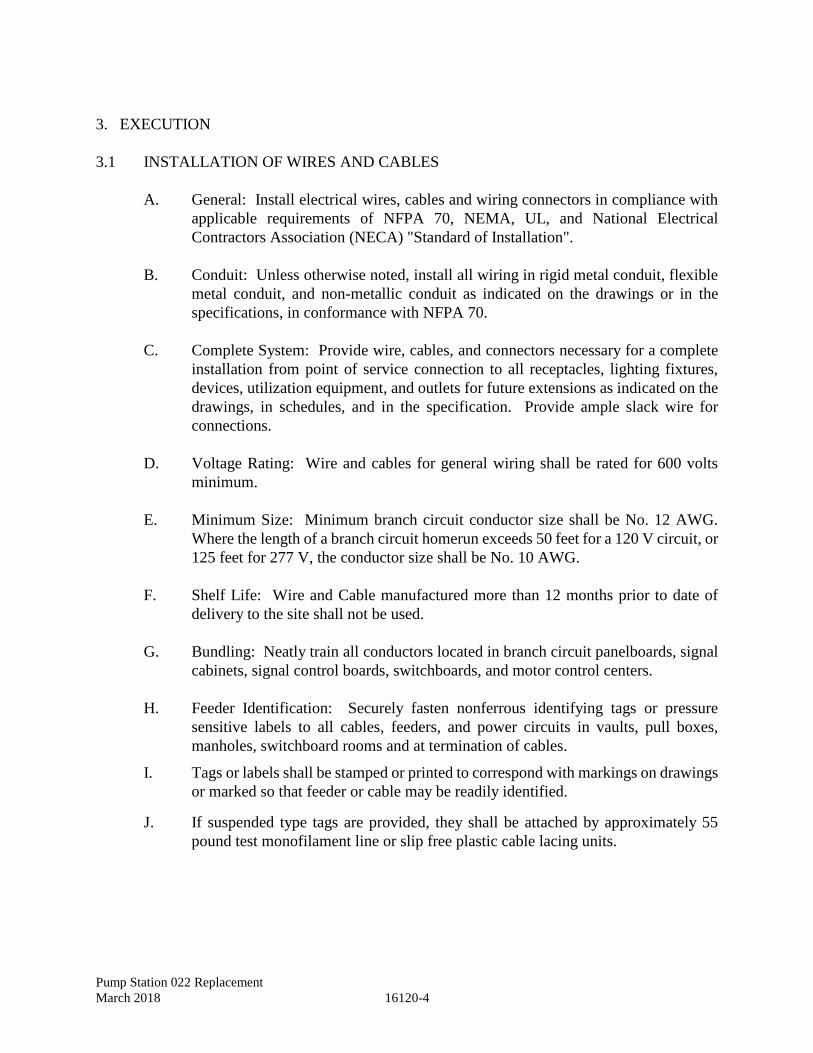
Pump Station 022 Replacement
March 2018 16120-4
3. EXECUTION
3.1 INSTALLATION OF WIRES AND CABLES
A. General: Install electrical wires, cables and wiring connectors in compliance with
applicable requirements of NFPA 70, NEMA, UL, and National Electrical
Contractors Association (NECA) "Standard of Installation".
B. Conduit: Unless otherwise noted, install all wiring in rigid metal conduit, flexible
metal conduit, and non-metallic conduit as indicated on the drawings or in the
specifications, in conformance with NFPA 70.
C. Complete System: Provide wire, cables, and connectors necessary for a complete
installation from point of service connection to all receptacles, lighting fixtures,
devices, utilization equipment, and outlets for future extensions as indicated on the
drawings, in schedules, and in the specification. Provide ample slack wire for
connections.
D. Voltage Rating: Wire and cables for general wiring shall be rated for 600 volts
minimum.
E. Minimum Size: Minimum branch circuit conductor size shall be No. 12 AWG.
Where the length of a branch circuit homerun exceeds 50 feet for a 120 V circuit, or
125 feet for 277 V, the conductor size shall be No. 10 AWG.
F. Shelf Life: Wire and Cable manufactured more than 12 months prior to date of
delivery to the site shall not be used.
G. Bundling: Neatly train all conductors located in branch circuit panelboards, signal
cabinets, signal control boards, switchboards, and motor control centers.
H. Feeder Identification: Securely fasten nonferrous identifying tags or pressure
sensitive labels to all cables, feeders, and power circuits in vaults, pull boxes,
manholes, switchboard rooms and at termination of cables.
I. Tags or labels shall be stamped or printed to correspond with markings on drawings
or marked so that feeder or cable may be readily identified.
J. If suspended type tags are provided, they shall be attached by approximately 55
pound test monofilament line or slip free plastic cable lacing units.

Pump Station 022 Replacement
March 2018 16120-5
3.2 WIRE PULLING AND CABLE INSTALLATION
A. Raceways: Refer to Section 16110, "Raceways", for the preparation of raceways for
wire and cables.
B. Equipment: Provide suitable installation equipment to prevent cutting and abrasion
of conduits during the pulling of wires and cables.
C. Ropes used for pulling of conductors shall be made of polyethylene or other suitable
nonmetallic material.
D. Metallic ropes shall not be used.
E. Pull conductors simultaneously where more than one is being installed in same
raceway.
F. Use pulling compound or lubricant where necessary; compound shall not deteriorate
conductor or insulation. Where polyethylene insulation is used and a pulling
lubricant is required, the lubricant shall be certified by the manufacturer to be non-
injurious to such insulation.
G. Lubricants shall conform to UL requirements applicable.
H. Pulling lines shall be attached to conductor cables by means of either woven basket
grips or pulling eyes attached directly to the conductors. Rope hitches shall not be
used.
I. Supports: Install cable supports for all vertical feeders in accordance with the
applicable sections of the NFPA 70.
J. Splices: Keep conductor splices to a minimum. Splice wires and cables only in
outlet boxes, junction boxes, pullboxes, manholes, and handholes.
K. In the making of a splice, connectors shall be brought up securely upon the
conductors such that all conductors are equally engaged, the insulation is not
ruptured, no bare wires are exposed or have "backed off" due to the application of
pressure, and the connection will not loosen due to cycling or vibration, in order to
insure an efficient splice.
L. The number, size, and combinations of conductors permitted as listed on
manufacturer's packaging of connector shall be strictly followed.
M. Connectors shall be fully insulated by a skirt, or taped to provide an insulation value
at least equal to rating of wires being connected.
N. Connectors: Tighten electrical connectors and terminals, including screws and bolts,
in accordance with manufacturer's published torque tightening values or comply with
tightening torques specified in UL 486A and 486B.
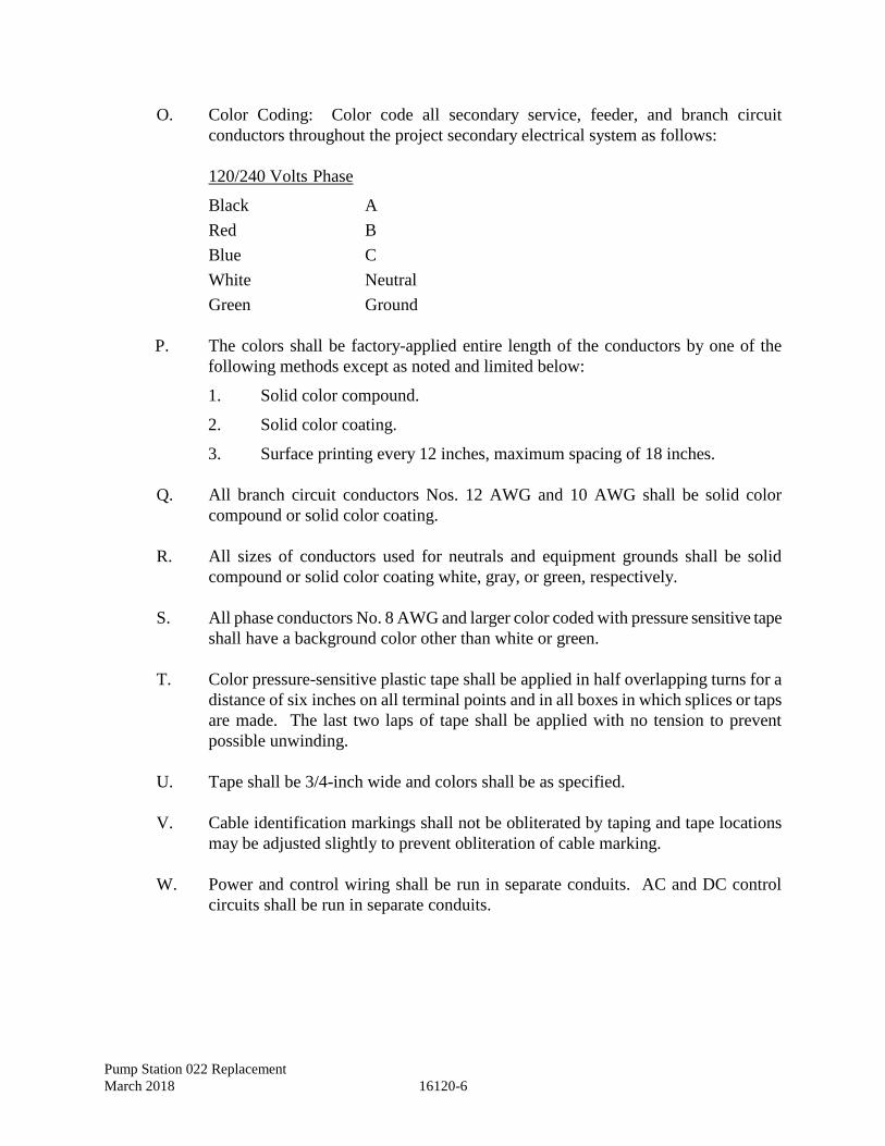
Pump Station 022 Replacement
March 2018 16120-6
O. Color Coding: Color code all secondary service, feeder, and branch circuit
conductors throughout the project secondary electrical system as follows:
120/240 Volts Phase
Black A
Red B
Blue C
White Neutral
Green Ground
P. The colors shall be factory-applied entire length of the conductors by one of the
following methods except as noted and limited below:
1. Solid color compound.
2. Solid color coating.
3. Surface printing every 12 inches, maximum spacing of 18 inches.
Q. All branch circuit conductors Nos. 12 AWG and 10 AWG shall be solid color
compound or solid color coating.
R. All sizes of conductors used for neutrals and equipment grounds shall be solid
compound or solid color coating white, gray, or green, respectively.
S. All phase conductors No. 8 AWG and larger color coded with pressure sensitive tape
shall have a background color other than white or green.
T. Color pressure-sensitive plastic tape shall be applied in half overlapping turns for a
distance of six inches on all terminal points and in all boxes in which splices or taps
are made. The last two laps of tape shall be applied with no tension to prevent
possible unwinding.
U. Tape shall be 3/4-inch wide and colors shall be as specified.
V. Cable identification markings shall not be obliterated by taping and tape locations
may be adjusted slightly to prevent obliteration of cable marking.
W. Power and control wiring shall be run in separate conduits. AC and DC control
circuits shall be run in separate conduits.
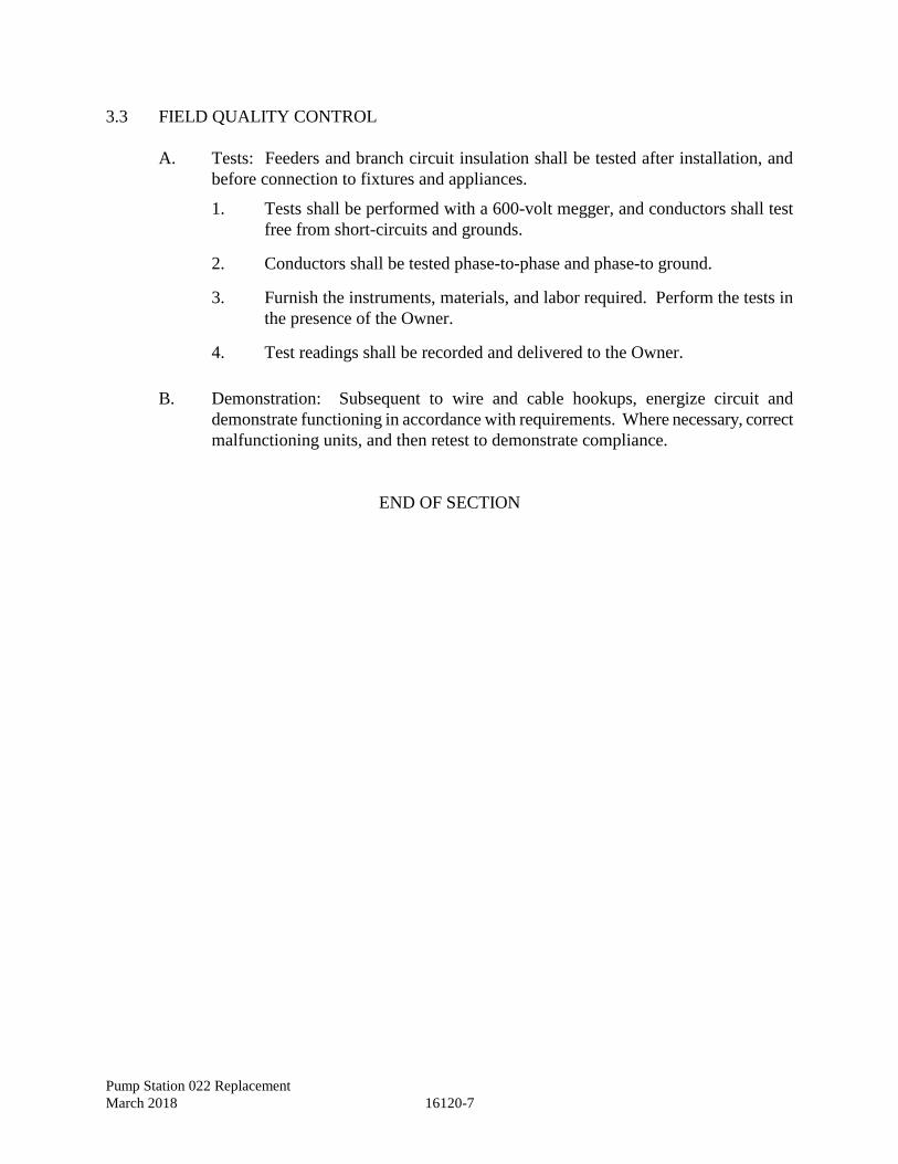
Pump Station 022 Replacement
March 2018 16120-7
3.3 FIELD QUALITY CONTROL
A. Tests: Feeders and branch circuit insulation shall be tested after installation, and
before connection to fixtures and appliances.
1. Tests shall be performed with a 600-volt megger, and conductors shall test
free from short-circuits and grounds.
2. Conductors shall be tested phase-to-phase and phase-to ground.
3. Furnish the instruments, materials, and labor required. Perform the tests in
the presence of the Owner.
4. Test readings shall be recorded and delivered to the Owner.
B. Demonstration: Subsequent to wire and cable hookups, energize circuit and
demonstrate functioning in accordance with requirements. Where necessary, correct
malfunctioning units, and then retest to demonstrate compliance.
END OF SECTION

Pump Station 022 Replacement
March 2018 16120-8
This Page Intentionally Left Blank
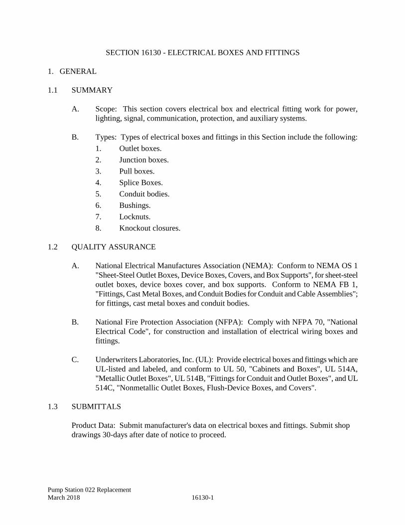
Pump Station 022 Replacement
March 2018 16130-1
SECTION 16130 - ELECTRICAL BOXES AND FITTINGS
1. GENERAL
1.1 SUMMARY
A. Scope: This section covers electrical box and electrical fitting work for power,
lighting, signal, communication, protection, and auxiliary systems.
B. Types: Types of electrical boxes and fittings in this Section include the following:
1. Outlet boxes.
2. Junction boxes.
3. Pull boxes.
4. Splice Boxes.
5. Conduit bodies.
6. Bushings.
7. Locknuts.
8. Knockout closures.
1.2 QUALITY ASSURANCE
A. National Electrical Manufactures Association (NEMA): Conform to NEMA OS 1
"Sheet-Steel Outlet Boxes, Device Boxes, Covers, and Box Supports", for sheet-steel
outlet boxes, device boxes cover, and box supports. Conform to NEMA FB 1,
"Fittings, Cast Metal Boxes, and Conduit Bodies for Conduit and Cable Assemblies";
for fittings, cast metal boxes and conduit bodies.
B. National Fire Protection Association (NFPA): Comply with NFPA 70, "National
Electrical Code", for construction and installation of electrical wiring boxes and
fittings.
C. Underwriters Laboratories, Inc. (UL): Provide electrical boxes and fittings which are
UL-listed and labeled, and conform to UL 50, "Cabinets and Boxes", UL 514A,
"Metallic Outlet Boxes", UL 514B, "Fittings for Conduit and Outlet Boxes", and UL
514C, "Nonmetallic Outlet Boxes, Flush-Device Boxes, and Covers".
1.3 SUBMITTALS
Product Data: Submit manufacturer's data on electrical boxes and fittings. Submit shop
drawings 30-days after date of notice to proceed.
Pump Station 022 Replacement
March 2018 16130-2
1.4 HAZARDOUS LOCATIONS
Raceway in designated hazardous or explosion proof locations shall conform to NFPA 70
requirements for installation.
2. PRODUCTS
2.1 GENERAL
A. Product Selection: Select boxes of types appropriate for each use and location.
1. Select covers for boxes of types appropriate for each use and location.
2. All switch plates and receptacle covers shall match the box that the plate
or cover are to be installed on.
3. Provide gaskets for covers of boxes in damp locations or where immersion
may occur.
2.2 FABRICATED MATERIALS
A. Interior Outlet Boxes: Provide PVC/Fiberglass enclosures, NEMA 12, outlet boxes.
1. Masonry Walls: 4-inch tall x 2 1/8 – inch wide x 2 ½ - inch deep
2. General use: 4 – inch square by 2 1/8 – inch deep
3. Hung devices: 4 – inch square by 2 1/8 – inch deep rated for the load
supported.
4. Two or More Ganged devices: 4 – inch tall x 2 ½ - inch deep by width as
required.
5. Exposed: 4 inch square by 2 1/8 – inch deep square.
B. Provide boxes of increased depth where required by the project. Coordinate spacing
of outlet boxes in fire rated walls.
C. Construction with stamped knockouts in the back and sides.
D. Provide threaded screw holes with corrosion-resistant screws for securing box covers
and wiring devices. Interior Outlet Box Accessories: Provide outlet box accessories
as required for each installation, including covers, mounting brackets, hangers,
extension rings, fixture studs, cable clamps, and metal straps for supporting outlet
boxes, which are compatible with outlet boxes being used and fulfilling requirements
of individual wiring situations. Interior accessories may be galvanized.
Pump Station 022 Replacement
March 2018 16130-3
E. Weatherproof Outlet Boxes: Provide corrosion-resistant PVC/Fiberglass
weatherproof outlet boxes, of types, shapes, and sizes, including depth of boxes, with
threaded conduit ends.
F. Interior Junction and Pull Boxes: Provide PVC/Fiberglass junction and pull boxes,
NEMA 12, with screw-on covers and of types, shapes, and sizes, to suit each
respective location and installation.
1. Conform to the applicable requirements of NFPA 70 and to UL 50 for boxes
over 100 cubic inches volume, except as modified below.
2. Where necessary for boxes to provide a rigid assembly, provide integral
structural bracing.
G. Junction and Pull Boxes, Below Grade: Provide junction and pull boxes, NEMA
6/3R, with screw-on covers and of types, shapes, and sizes, to suit each respective
location and installation.
H. Conduit Bodies: Interior conduit bodies shall be PVC/Fiberglass construction.
Exterior conduit bodies shall be PVC coated rigid galvanized steel.
I. Bushings, Knockout Closures and Locknuts: Provide knockout closures, conduit
locknuts, conduit bushings, and offset connectors of types and sizes to suit respective
uses and installation.
J. All hardware to be corrosion-resistant. Interior hardware may be galvanized. All
exterior hardware shall be stainless steel.
3. EXECUTION
3.1 INSTALLATION OF ELECTRICAL BOXES AND FITTINGS, GENERAL
A. Coordination: Coordinate installation of electrical boxes and fittings with
wire/cable and raceway installation work, and with the work of other trades.
B. Knockout Caps: Provide knockout closures to cap unused knockout holes where
blanks have been removed.
C. Anchoring: Support and fasten boxes securely.
D. Sizes: Provide boxes of sizes adequate to meet NFPA 70 volume requirements, but
in no case smaller than sizes indicated.
3.2 INSTALLATION OF OUTLET BOXES
A. Coordination: Verify location of outlet boxes with other equipment.
Pump Station 022 Replacement
March 2018 16130-4
B. Grounding: Provide each box to which a device is to be attached with a grounding
terminal, consisting of either a green-colored washer-in-head machine screw, not
smaller than No. 10-32, screwed into a tapped hole or a grounding bushing attached
to one of the conduits.
C. Mounting Height: The "mounting height" of a wall-mounted outlet box is defined as
the height from the finished floor to the horizontal centerline of the cover plate for
receptacles and top of the outlet box for switches.
D. Where mounting heights are not indicated or where heights and locations interfere
with mechanical, architectural or structural features, install outlet boxes in an
approved location, without additional cost.
E. Where mounting heights for switches mounted in masonry walls shall be 46 inches or
top of coursing not to exceed 48 inches. Do not mount outlet box in the mortar joint.
F. Vertical Axis: Except as otherwise indicated, mount outlet boxes for switches with
the long axis vertical.
1. Mount boxes for receptacles vertically.
2. Three or more gang boxes shall be mounted with the long axis horizontal.
I. Prohibited Work:
1. Do not use sectional (gangable) boxes.
2. Do not use device plates as covers for boxes in exposed locations.
3. Do not use round boxes where conduit must enter box through side of box,
which would result in difficult and insecure connections when fastened with
locknut or bushing on rounded surface.
K. Protection: Protect outlet boxes to prevent entrance of debris. Thoroughly clean
foreign material from boxes before conductors are installed.
L. Threaded Hubs: At the following locations use threaded hub type boxes with
gasketed weatherproof covers:
1. Exterior locations.
2. Where installed on unfinished walls. Cover gaskets may be omitted in dry
locations.
3. Where exposed to moisture laden atmosphere.
3.3 PULL AND JUNCTION BOXES
A. Installation: For installation of junction and pull boxes, conform to NFPA 70 and the
following:
Pump Station 022 Replacement
March 2018 16130-5
1. For boxes exposed to rain or installed in wet locations use weatherproof type.
2. Do not exceed 6 conductors entering and 6 leaving raceways in a single box.
B. Number of conductors in any pull or junction box including equipment grounding
conductors shall not exceed the maximum allowed by NEC 314.
C. Supports: Provide in each box, sufficient clamps, grids, or devices to which cables
are secured in neat and orderly fashion permitting ready identification.
D. Adjacent Boxes: Locate adjacent boxes a minimum of 2 feet from any other pull or
junction box.
END OF SECTION

Pump Station 022 Replacement
March 2018 16130-6
This Page Intentionally Left Blank
Pump Station 022 Replacement
March 2018 16135-1
SECTION 16135 - WIRING DEVICES
1. GENERAL
1.1 SUMMARY
A. Scope: Extent of wiring device work is indicated on drawings and schedules, by
requirements of this Section, and Section 16010, "Electrical Basic Requirements".
B. Types: Types of electrical wiring devices specified in this Section include the
following:
1. Receptacles.
2. Ground-fault circuit interrupters.
3. Switches.
4. Wallplates.
5. Plugs and connectors.
C. Related Sections: Refer to other sections of Division 16 for the following:
1. Wire and Cables.
2 Boxes.
1.2 QUALITY ASSURANCE
Codes: Provide wiring devices conforming to the following:
A. American National Standards Institute (ANSI): Provide plugs and receptacle devices
constructed in accordance with ANSI C73, "Attachment Plugs and Receptacles,
Dimensions of".
B. Institute of Electrical and Electronics Engineers (IEEE): Construct and install wiring
devices in accordance with requirements of IEEE 241, "Recommended Practice for
Electric Power Systems in Commercial Buildings".
C. National Electrical Manufacturers Association (NEMA): Provide wiring devices
constructed and configured in accordance with the requirements of:
1. WD 1 General Requirements for Wiring Devices.
2. WD 2 Semiconductor Dimmers for Incandescent Lamps.
3. WD 6 Wiring Devices - Dimensional Requirements.
D. National Fire Protection Association (NFPA): Comply with NFPA 70, "National
Electrical Code", as applicable to construction and installation of electrical wiring
devices.
Pump Station 022 Replacement
March 2018 16135-2
E. Underwriters Laboratories, Inc. (UL): Provide wiring devices, which are UL
listed, and comply with the requirements of:
1. 20 General- Use Snap Switches.
2. 49 Attachment Plugs and Receptacles.
3. 514A Metallic Outlet Boxes.
4. 514B Fittings for Conduit and Outlet Boxes.
5. 514C Nonmetallic Outlet Boxes, Flush-Device Boxes, and Covers.
6. 943 Ground-Fault Circuit Interrupters.
1.3 SUBMITTALS
Submit manufacturer's data on electrical wiring devices. Submit shop drawings 30-days
after date of notice to proceed.
1.4 DELIVERY, STORAGE, AND HANDLING
A. Delivery and Handling: Handle wiring devices carefully to prevent damage. Do not
install damaged wiring devices, replace with new.
B. Storage: Store wiring devices in a clean and dry place. Protect from dirt,
construction debris, and physical damage.
2. PRODUCTS
2.1 WIRING DEVICES
Provide factory-fabricated wiring devices, in types, colors, and electrical ratings for
applications indicated and which comply with NEMA WD 1.
2.2 RECEPTACLES
A. Duplex Receptacles: Provide specification grade duplex receptacles, 2-pole, 3-wire a
grounding, with green hexagonal equipment ground screw, ground terminals and
poles internally connected to mounting yoke, 20 A, 125 V, with metal plaster ears,
design for side wiring with four captively held binding screws and provisions for
back wiring from eight separate metal wiring clamps, with spring loaded, screw
activated pressure plate, with NEMA configuration 5-20R unless otherwise indicated.
Self-grounding or automatic type grounding receptacles are not acceptable in lieu of
receptacles with separate grounding screw lugs and a direct, green insulated
conductor connection to the equipment grounding system.
Pump Station 022 Replacement
March 2018 16135-3
B. Single Receptacles: Provide specification grade single receptacles, 2-pole, 3-wire,
grounding, with green hexagonal equipment ground screw, 20 A, 125 V, with metal
plaster ears, design for side and back wiring with spring loaded, screw activated
pressure plate, with NEMA configuration 5-20R unless otherwise indicated.
C. Ground Fault Interrupter: Provide termination type ground fault circuit interrupters,
with duplex receptacles, capable of protecting connected receptacles on single circuit,
and installed in an outlet box without adaptor. Provide grounding type UL rated
Class A, Group 1, rated 20 A, 125 V, 60 Hz; solid-state ground fault sensing and
signaling with 5 milliamperes ground fault trip level, equip with NEMA
configuration 5-20R.
D. Weatherproof Receptacles: Provide in cast metal box with gasketed, weatherproof
PVC cover plate and shall be listed as "raintight while in use".
2.3 SWITCHES
A. General: Provide specification grade switches with green hexagonal equipment
ground screw, as indicated on the drawings conforming to NEMA WD 1 and to the
following:
B. Snap Switches: Provide specification grade, general duty flush single pole toggle AC
quiet switches, 20 A, 120-277 V, with mounting yoke insulated from mechanism,
equip with plaster ears, switch handle and back or side-wired screw terminals.
Provide captive or terminal type terminal screws not smaller than No. 8. Provide
back-wired devices with separate access holes for wiring.
2.4 WIRING DEVICE ACCESSORIES
A. Wallplates: Provide wall plate for each switch, receptacle, and special purpose
outlet. Do not use sectional gang plates. Provide multi-gang outlet plates for multi-
gang boxes. Wall plates shall be in accordance with UL 514A, UL 514B, UL 514C,
and as follows unless otherwise noted.
B. Cover plates for flush mounted wiring devices shall be stainless steel, standard size,
single or ganged as shown on the drawings. Cover plate mounting screws shall be
slotted head oval screws and shall match the finish and material of the plate, and shall
be furnished with the plate by the plate manufacturer.
C. Switch and receptacle cover plates on exposed work shall be galvanized cast ferrous
metal or Feraloy, standard size, and shall be single or ganged as indicated on the
drawings.
Pump Station 022 Replacement
March 2018 16135-4
D. Exterior mounted switch and receptacle plates, and those noted to be weatherproof,
shall be gasketed weatherproof PVC cover plates, standard size, single or ganged as
indicated on the drawings, and shall be listed as "raintight while in use".
3. EXECUTION
3.1 INSTALLATION OF WIRING DEVICES
A. General: Install wiring devices as indicated, in accordance with manufacturer's
written instructions, applicable requirements of NFPA 70 and NEMA "Standard of
Installation", and in accordance with recognized industry practices to fulfill project
requirements. Where not indicated, mount switch adjacent to latch jamb of door.
B. Coordination: Coordinate with other work, including painting, electrical boxes and
wiring work, as necessary to interface installation of wiring devices with other work.
C. Boxes: Install wiring devices only in electrical boxes, which are clean; free from
excess building materials, dirt, and debris.
D. Receptacles: Install receptacles with centerline located 18-inches above the finished
floor, unless otherwise noted or specified.
E. Work Sequence: Install wiring devices after wiring work is completed.
F. Switches: Install switches with centerline located 48 inches above finished floor
unless otherwise noted or specified.
3.2 PROTECTION OF WALL PLATES AND RECEPTACLES
Upon installation of wall plates and receptacles, advise Owner's representative regarding
proper and cautious use of convenience outlets. At time of substantial completion, replace
those items, which have been damaged, including those burned and scored by faulty plugs.
3.3 GROUNDING
Provide equipment grounding connections for wiring devices, unless otherwise indicated.
3.4 TESTING
Test wiring devices for electrical continuity, and for short-circuits prior to energizing
circuitry. Ensure proper polarity of connections is maintained. Subsequent to energization,
test wiring devices to demonstrate compliance with requirements.
END OF SECTION
Pump Station 022 Replacement
March 2018 16190-1
SECTION 16190 - SUPPORTING DEVICES
1. GENERAL
1.1 SUMMARY
A. Scope: Provide support for all electrical items using supports, anchors, sleeves, seals,
fastenings, and other components. The extent of supporting devices is covered by
this Section, the drawings and Section 16010, "Electrical Basic Requirements".
B. Types: Types of supports, anchors, sleeves, seals and fastenings specified in this
Section include the following:
1. Clevis hangers.
2. Riser clamps.
3. C-clamps.
4. I-beam clamps.
5. One-hole conduit straps.
6. Two-hole conduit straps.
7. Round steel rods.
8. Lead expansion anchors.
9. Toggle bolts.
10. Wall and floor seals.
C. Equipment: Supports, sleeves, seals and fasteners furnished as part of factory-
fabricated equipment, are specified as part of equipment assembly in other sections.
1.2 QUALITY ASSURANCE
A. National Fire Protection Association (NFPA): Comply with NFPA 70 as applicable
to construction and installation of electrical supporting devices.
B. Underwriters Laboratories, Inc. (UL): Conform to UL listings and labeling.
Pump Station 022 Replacement
March 2018 16190-2
2. PRODUCTS
2.1 PRODUCTS
A. General: Provide supporting devices with manufacturer's standard materials,
designed and constructed in accordance with published product information, for a
complete installation and as herein specified.
B. Corrosion Resistance: Provide all supports, support hardware, and fasteners hot-
dipped galvanized or cadmium plated.
C. For Raceway Supports: Provide manufacturer's standard supports including clevis
hangers, riser clamps, conduit straps, threaded C-clamps with retainers, ceiling
trapeze, wall brackets and spring steel clamps.
D. Fasteners: Provide fasteners of types, sizes, and materials indicated with the
following construction features:
1. 1/2-inch lead expansion anchors approximately 38 pounds weight per 100
units.
2. 3/16-inch by 4-inch springhead toggle bolts approximately 5 pounds weight
per 100 units.
E. Sleeves and Seals: Provide sleeves and seals, of types, sizes and materials
indicated with the following features:
1. Smoke and fire stop seals shall have a UL fire rating of where installed in fire
rated construction or as indicated.
2. Seal between sleeve and pipe where a fire rated seal is not required or
specified. Weatherproof seals required for penetrations thru exterior walls.
Seals capable of withstanding a corrosive environment and sulfide gases are
required for penetrations into the wet well.
3. U-Channel Strut Systems: Provide U-channel strut system for mounting and
supporting electrical equipment. Fabricate strut from 16-gauge hot-dip
galvanized steel sheet, 9/16-inch diameter holes, and 8-inches on center on
top surface. Fittings shall mate with the U-channel.
Pump Station 022 Replacement
March 2018 16190-3
3. EXECUTION
3.1 INSTALLATION
A. Compliance: Install hangers, sleeves, seals, U-channel supports and fasteners as
indicated and in accordance with manufacturer's written instructions. Comply
with requirements of NFPA 70 and American National Standards Institute
(ANSI)/National Electrical Manufacturers Association (NEMA) for installation of
supporting devices.
B. Coordination: Coordinate with other electrical work, including raceway and wiring
work.
C. Raceway Supports:
1. Provide raceway support meeting the requirements of these specifications and
NFPA 70. Conform to manufacturer's recommendations. For each support
provide strength equal to the maximum weight of the present load and all
future raceways for which the support provides space, times a safety factor.
Except as otherwise indicated, use a safety factor greater than four where
necessary to provide a minimum safety allowance of 200 pounds. Provide
additional support strength where required to prevent distortion of raceway
during wire pulling.
2. Provide individual and multiple (trapeze) raceway hangers, and riser clamps
as necessary to support raceways. Provide U-bolts, clamps, attachments, and
other hardware necessary for hanger assembly, and for securing hanger rods
and conduits.
3. Arrange for grouping of parallel runs of horizontal raceways to be supported
together on trapeze type hangers where possible.
D. Exposed conduits installed on the interior surface of exterior building walls shall
be spaced off the wall surface a minimum of 1/4-inch using "clamp-backs" or
strut.
E. Support individual horizontal conduits and EMT 1-1/2-inch size and smaller by
either one-hole pipe straps or separate pipe hangers, use separate pipe hangers for
larger sizes. Use steel fasteners that are specifically designed for supporting single
conduits or EMT. Unless otherwise indicated, do not use wire as a means of support.
F. Except as otherwise indicated, space supports for metallic and non-metallic raceways
in accordance with the requirements of this Section and the requirements of the
NFPA 70.
Pump Station 022 Replacement
March 2018 16190-4
G. Provide support for exposed or concealed raceway as close as practical to and not
exceeding one foot from an unsupported box or access fitting. In horizontal runs, a
support at a box or access fitting may be omitted when the box or access fitting is
independently supported and the raceway termination is not made with a close nipple
or threadless box connector.
H. In vertical runs, provide such support that the load produced by the weight of the
raceway and the enclosed conductors is carried entirely by the conduit supports, with
no weight load on raceway terminations or conductor terminals.
I. Miscellaneous Supports:
1. Provide supports for all miscellaneous electrical components as required to
produce the same safety allowances as specified for raceway supports above.
Provide metal channel racks for mounting cabinets, panelboards, disconnects,
control enclosures, pull boxes, junction boxes, etc.
2. In open overhead spaces, cast boxes threaded to raceways need not be
separately supported except where used for fixture support and to the extent
necessary to prevent movement during wire installation; support sheet metal
boxes directly from the building structure or by bar hangers. Where bar
hangers are used, attach the bar to raceways on opposite sides of the box and
support the raceway with an approved type fastener not more than 24-inches
from the box. When penetrating reinforced-concrete members, avoid cutting
any reinforcing steel.
J. Cable Supports:
1. Install in strict compliance with manufacturer's instructions.
2. Spacing not to exceed NFPA 70 tabulation for spacing of conductor supports.
3. Allow adequate slack in conductors to prevent any stress on terminations.
Take into consideration conductor thermal contraction.
K. Fasteners:
1. Unless otherwise indicated securely fasten all electrical items and their
supporting hardware including, but not limited to, conduits, raceways, cables,
cable trays, busways, cabinets, panelboards, wall-mounted transformers,
boxes, disconnect switches and control components to the building structure.
Pump Station 022 Replacement
March 2018 16190-5
2. Fasten by means of wood screws or screw-type nails on wood; by toggle bolts
on hollow masonry units; by concrete inserts or expansion bolts on concrete
or brick; by machine screws; welded threaded studs, or spring-tension clamps
on steel work. Threaded studs driven in by a powder charge and provided
with lock washers and nuts may be used instead of expansion bolts or
machine or wood screws in special circumstances. Do not weld conduits or
pipe straps to steel structures.
3. Holes cut to a depth of more than 1-1/2-inches in reinforced concrete beams
or to a depth of more than 3/4-inch in concrete joints shall not cut the main
reinforcing bars. Fill holes that are not used.
4. Loads applied to any fastener shall not exceed one-fifth of the proof test load.
Use vibration and shock-resistant fasteners.
L. Sleeve Seals:
1. Tighten sleeve seal nuts until sealing grommets have expanded to form
watertight and smoketight seal.
2. Sleeves: Where installed in slabs or partitions completely fill the void
between the sleeve and masonry with expanding cement grout.
END OF SECTION

Pump Station 022 Replacement
March 2018 16190-6
This Page Intentionally Left Blank
Pump Station 022 Replacement
March 2018 16195-1
SECTION 16195 - ELECTRICAL IDENTIFICATION
1. GENERAL
1.1 SUMMARY
A. Scope: Extent of electrical identification work required by this Section is indicated
in this section, on the drawings or where specified in other sections of Division 16.
B. Types: Types of electrical identification work specified in this section include the
following:
1. Identification of electrical power, control and communication raceways,
cables, and conductors.
2. Equipment labels and signs.
C. Related Sections: Refer to other sections for the following:
1. Electrical Basic Requirements.
1.2 QUALITY ASSURANCE
A. National Fire Protection Association (NFPA): Comply with NFPA 70, "National
Electrical Code" requirements for identification and for provision of warning and
caution signs for wiring and equipment.
1.3 SUBMITTALS
A. Product Data: Submit manufacturer's data on electrical identification materials and
products.
2. PRODUCTS
2.1 PRODUCTS
A. General: Except as otherwise indicated, provide manufacturer's standard products of
categories and types required for each application.
B. Furnish and install engraved laminated phenolic nameplates for all safety switches,
panelboards, starters, and other electrical equipment supplied for the project for identification
of equipment, controlled, served, phase, voltage, etc. Nameplates shall be securely attached
to equipment with self-tapping stainless steel screws, riveted or bolted and shall identify
equipment controlled, attached, etc. Letters shall be approximately 1/2-inch high minimum
for identification and 1/4-inch high minimum for other descriptions. Embossed, self-adhesive
plastic tape is not acceptable for marking equipment. Nameplate material colors shall be:
1. Blue surface with white core for 120/240 volt equipment.
Pump Station 022 Replacement
March 2018 16195-2
C. All empty conduit runs and conduit with conductors for future use shall be
identified for use and shall indicate where they terminate. Identification shall be
by tags with wire attached to conduit or outlet.
D. Wire/Cable Designation Tape Markers: Provide vinyl or vinyl cloth, self-adhesive
wrap-around cable/conductor markers with pre-printed numbers and letters for
designation purposes.
E. Cable Ties: Provide fungus-inert, self-extinguishing, one piece, self locking nylon
cable ties, 0.18-inch minimum width, 50 pounds minimum tensile strength and
suitable for a temperature range from -50 degrees F. to +350 degrees F. Provide ties
in specified colors when used for color coding.
3. EXECUTION
3.1 APPLICATION AND INSTALLATION
A. General Installation Requirements:
1. Coordinate names, abbreviations and other designations used in electrical
identification work, with corresponding designations, specified or indicated
on drawings. Provide numbers, lettering and wording as approved in
submittals, as required by code, or as recommended by manufacturers.
2. Install products covered by this section where indicated on drawings or
specified. Install products covered by this section where required by NFPA
70, whether or not otherwise indicated. Install products in accordance with
manufacturer's written instructions and requirements of NFPA 70.
3. Where identification is to be applied to surfaces, which require finish, install
identification after completion of finish work.
B. Panel Identification
1. All electrical and instrumentation panels shall have legend plates that denote the
following information:
a. EQUIPMENT NAME (ex. WATER PUMP CONTROL #1)
b. EQUIPMENT IDENTIFICATION NUMBER (ex. FP-50-10-1)
c. SOURCE BREAKER IDENTIFICATION (ex. FED FROM MCC-4)
2. All devices that have more than one source of voltage will have a similar plastic
laminate label, red w/white lettering that clearly states the presence of additional
voltage sources. It also shall be secured to the panel in a similar fashion as the
previously mentioned legend plates.
Pump Station 022 Replacement
March 2018 16195-3
3. All terminal devices such as solenoids, limit switches, level probes, thermostats,
etc. shall have labels made of material identical to that previously mentioned.
They also shall be black w/white lettering and secured with 30# stainless steel
beaded chain or attached with an appropriate adhesive.
4. All lettering shall be engraved block font, 3/8 Inch high.
C. Panel Items
1. Lens colors shall be “green” for run, open, or on; “red” for stopped, off or
alarms for vfd’s, pumps, motors; “amber” for high and low liquid level alarms.
2. Pilot lights shall be full voltage LED cluster style.
3. The local stop pushbutton will be a red head maintained type device and local
start button will be black head momentary type devices.
4. Terminal strips shall be provided for all panels and shall be of the flanged fork
or ring lug type suitable for No.12 AWG stranded wire minimum. Provide 25
percent spare terminals in each panel
D. Tagging or Labeling Conductors: Tag or label conductors as follows:
1. Match identification markings with designations used in panelboards, shop
drawings, contract documents, and similar previously established
identification schemes for the facility electrical work.
END OF SECTION

Pump Station 022 Replacement
March 2018 16195-4
This Page Intentionally Left Blank
Pump Station 022 Replacement
March 2018 16410-1
SECTION 16410 - PUMP CONTROL PANEL
1. GENERAL
1.1 DESCRIPTION
A. Scope
1. Furnish and install a complete Pump Control Panel (PCP) and related
auxiliary control components for the sewage pump station to provide for
control of the two (2) raw sewage pumps and other equipment. The PCP
shall be complete and include all components and wiring as shown on the
Drawings and specified herein.
B. Related Sections:
1. 16010 – Electrical Basic Requirements
2. 16120 – Wires and Cables
3. 16450 – Grounding
4. 16470 – Panelboards
5. 16475 – Molded Case Circuit Breakers (MCCB)
6. 16690 – Variable Frequency Drives
7. 16920 – Programmabel Logic Controller
1.2 REFERENCES
A. The most current edition in effect for the publications listed below form a part of
this specification to the extent referenced. The publications are referred to in the
text by the basic designation only. The referenced publications shall be the current
effective edition.
1. AMERICAN NATIONAL STANDARDS INSTITUTE (ANSI)
a. ANSI C2 - National Electrical Safety Code
b. ANSI C12.1 - Code for Electricity Metering
c. ANSI C12.4 - Mechanical Demand Registers
d. ANSI C12.10 - Electromechanical Watthour Meters
e. ANSI C39.1 - Requirements for Electrical Analog Indicating
Instruments
Pump Station 022 Replacement
March 2018 16410-2
2. AMERICAN SOCIETY FOR TESTING AND MATERIALS (ASTM)
a. ASTM B 8 - Concentric-Lay-Stranded Copper Conductors, Hard,
Medium-Hard, or Soft
b. ASTM D 709 - Laminated Thermosetting Materials
3. AMERICAN SOCIETY OF MECHANICAL ENGINEERS (ASME)
a. ASME - Boiler and Pressure Vessel Code Industrial, Scientific,
and Medical Equipment
4. INSTITUTE OF ELECTRICAL AND ELECTRONICS ENGINEERS,
INC. (IEEE)
a. IEEE 100 - Dictionary of Electrical and Electronics Terms
b. IEEE ANSI/IEEE C57.13 - Instrument Transformers
5. INSTRUMENTATION, SYSTEMS AND AUTOMATION SOCIETY
(ISA)
a. ANSI/ISA 5.1 - Instrumentation Symbols and Identification
6. NATIONAL ELECTRICAL MANUFACTURERS ASSOCIATION
(NEMA)
a. NEMA AB 1 - Molded Case Circuit Breakers and Molded Case
Switches
b. NEMA FU 1 - Low Voltage Cartridge Fuses
c. NEMA ICS 1 - Industrial Control and Systems: General
Requirements
d. NEMA ICS 2 - Industrial Control and Systems Controllers,
Contactors, Overload Relays Rated Not More Than 2,000 Volts
AC or 750 DC
e. NEMA ICS 3 - Industrial Control and Systems Factory Built
Assemblies
f. NEMA ICS 4 - Industrial Control and Systems: Terminal Blocks
g. NEMA ICS 6 - Industrial Control and Systems Enclosures
h. NEMA MG 1 - Motors and Generators
Pump Station 022 Replacement
March 2018 16410-3
i. NEMA 250 - Enclosures for Electrical Equipment (1000 Volts
Maximum)
7. NATIONAL FIRE PROTECTION ASSOCIATION (NFPA)
a. NFPA 70 - National Electrical Code
8. UNDERWRITERS' LABORATORIES (UL)
a. UL 50 - Enclosures for Electrical Equipment
b. UL 83 - Thermoplastic Insulated Wires and Cables
c. UL 198B - Class H Fuses
d. UL 467 - Grounding and Bonding Equipment
e. UL 486A - Wire Connectors and Soldering Lugs for Use with
Copper Conductors
f. UL 486E - Equipment Wiring Terminals for Use with Aluminum and/or
Copper Conductors
g. UL 489 - Molded Case Circuit Breakers, Molded Case Switches,
and Circuit Breaker Enclosures
h. UL 508 - Industrial Control Equipment
i. UL 510 - Insulating Tape
j. UL 512 - Fuseholders
k. UL 854 - Service Entrance Cables
l. UL 1004 - Electric Motors
1.3 QUALITY ASSURANCE
A. All PCP components shall be of the most current and proven design.
Specifications and Drawings call attention to certain features but do not purport to
cover all details entering into the design of the PCP. The components provided
by the Panel Supplier shall be compatible with the functions required and shall
form a complete working system. The PCP shall be UL listed as a complete
assembly in accordance with UL-508.
B. Workmanship
1. Materials and equipment shall be installed in accordance with NFPA 70,
recommendations of the manufacturer, and as shown.
Pump Station 022 Replacement
March 2018 16410-4
1.4 GENERAL CONDITIONS
A. The installation shall conform to the requirements of NFPA 70, unless more
stringent requirements are indicated herein or shown.
B. Coordination:
1. The drawings indicate the extent and the general location and arrangement
of equipment. The Contractor shall become familiar with all details of the
work and verify all dimensions in the field so that the equipment shall be
properly located and readily accessible. Equipment and materials shall be
located to avoid interference with mechanical or structural features. If any
conflicts occur necessitating departures from the drawings, details of and
reasons for departures shall be submitted to the Owner and approved prior
to implementing any change.
C. Standard Products
1. Material and equipment shall be new and of the minimum quality
specified and shall be a standard product of a manufacturer regularly
engaged in the manufacture of the product and shall essentially duplicate
items that have been in satisfactory use for at least 5 years prior to bid
opening. Used, recycled or rehabilitated material or equipment will not be
acceptable.
D. Identification Nameplates
1. Major items of electrical equipment and major components shall be
permanently marked with an identification name to identify the equipment
by type or function and specific unit number as indicated. Unless
otherwise specified, identification nameplates shall be made of laminated
phenolic in accordance with ASTM D 709 with black outer layers and a
white core. Edges shall be chamfered. Plates shall be fastened with black
finished round head drive screws or approved nonadhesive metal
fasteners. When the nameplate is to be installed on an irregular shaped
object, the Contractor shall devise an approved support suitable for the
application and ensure the proper installation of the supports and
nameplates. In all instances, the nameplate shall be installed in a
conspicuous location. At the option of the Contractor, the equipment
manufacturer's standard embossed nameplate material with black paint
filled letters may be furnished in lieu of laminated phenolic. The
following equipment, as a minimum, shall be provided with identification
nameplates:
Minimum 1/4 inch Minimum 1/8 inch
High Letters High Letters
Starters Control Power Transformers
Equipment Enclosures Control and Pilot Devices
Pump Station 022 Replacement
March 2018 16410-5
1.5 SUBMITTALS
A. Submit the following in accordance with Section 01300, "Submittals”. Submit
shop drawings 30-days after date of notice to proceed.
1. Product Data: Submit manufacturer’s catalog data, shop drawings,
certifications and installation instructions for the following:
a. Pump Control Panel and its Associated Components
b. Circuit Breakers
c. Switches
d. Relays
e. Fuses
f. Instruments
g. Enclosures
h. Starters, Automatic Control Devices
i. Programmable Logic Controller
j. Meters
k. Variable Frequency Drives
l. Float Switches
m. Gauges
n. Wet Well Level Sensing System
o. 24v backup power supplies
p. Discharge Pressure Transducer
q. Flow Meter
r. Proximity Switches
Pump Station 022 Replacement
March 2018 16410-6
2. Shop Drawings
a. Contractor to submit full drawings containing complete wiring and
schematic diagrams and any other details required to demonstrate
that the system has been coordinated and will properly function as
a unit. Drawings shall show proposed layout and anchorage of
equipment and appurtenances, and equipment relationship to other
parts of the work including clearances for maintenance and
operation.
b. Submit detail drawings consisting of equipment drawings,
illustrations, schedules, instructions, diagrams, and other
information necessary to define the installation. Detail drawings
shall show the rating of items and systems and how the
components of an item and system are assembled, function
together, and how they will be installed on the project. Data and
drawings for component parts of an item or system shall be
coordinated and submitted as a unit. Data and drawings shall be
coordinated and included in a single submission. Multiple
submissions for the same equipment or system are not acceptable
except where prior approval has been obtained from the Owner. In
such cases, a list of data to be submitted later shall be included
with the first submission. Detail drawings shall show physical
arrangement, construction details, connections, finishes, materials
used in fabrication, provisions for conduit entrance, access
requirements for installation and maintenance, physical size,
electrical characteristics, foundation and support details, and
equipment weight. Drawings shall be drawn to scale and/or
dimensioned. Optional items shall be clearly identified as included
or excluded. Detail drawings shall as a minimum include:
i. Pump control panel layout.
ii. Single line electrical diagrams including primary, metering,
sensing, and relaying, control wiring, and control logic.
Pump Station 022 Replacement
March 2018 16410-7
iii. Electrical drawings including single line diagrams, and
schematics or elementary diagrams of each electrical
system; internal wiring and field connection diagrams of
each electrical device when published by the manufacturer;
wiring diagrams of cabinets, panels, units, or separate
mountings; interconnection diagrams that show the wiring
between separate components of assemblies; field
connection diagrams that show the termination of wiring
routed between separate items of equipment; internal
wiring diagrams of equipment showing wiring as actually
provided for this project. Field wiring connections shall be
clearly identified.
c. If departures from the contract drawings are deemed necessary by
the Contractor, complete details of such departures, including
changes in related portions of the project and the reasons why,
shall be submitted with the detail drawings. Approved departures
shall be made at no additional cost to the Owner.
3. Test Reports
a. Factory Test Reports.
i. Contractor to provide six copies of the information
described below in 8 1/2 x 11 inch binders having a
minimum of 5 rings from which material may readily be
removed and replaced, including a separate section for each
test. Sections shall be separated by heavy plastic dividers
with tabs.
(1) A list of equipment used, with calibration
certifications.
(2) A copy of measurements taken.
(3) The dates of testing.
(4) The equipment and values to be verified.
(5) The conditions specified for the test.
(6) The test results, signed and dated.
(7) A description of adjustments made.
Pump Station 022 Replacement
March 2018 16410-8
b. Operational Testing Plan
i. Detailed testing protocol at least 30 days prior to scheduled
operational tests to demonstrate pumping system
operational tests. The protocol shall describe all tests to be
conducted and the inter-relationships thereof. Operational
testing will not be scheduled or performed until the
contractors test plan is approved.
c. Operational Testing Report
i. A detailed operational testing and equipment adjustment
report within 30 days of completion of successful
operational tests and prior to final acceptance testing.
Performance test reports in booklet form showing all
operational tests performed to adjust each component and
all operational tests performed to prove compliance with
the specified performance criteria, upon completion and
testing of the installed systems. Each test report shall
indicate the final position of all control functions.
ii. Submit the information described below in 8 1/2 x 11 inch
binders, including a separate section for each test. Sections
shall be separated by heavy plastic dividers with tabs.
(1) Contractor’s certification that the operational tests
were satisfactorily completed, all deficiencies were
corrected and successfully retested, and that the
pump station is ready for Final Acceptance Testing.
(2) A list of equipment used, with calibration
certifications.
(3) A copy of measurements taken.
(4) The dates of testing.
(5) The equipment and values to be verified including
acceptable reference values.
(6) The conditions specified for the test.
(7) The test results, signed and dated.
(8) A description of adjustments made.
(9) Final position of controls and device settings.
Pump Station 022 Replacement
March 2018 16410-9
d. Final Acceptance Test Plan
i. Detailed testing protocol at least 14 days prior to scheduled
final acceptance testing to demonstrate pumping system
operations and compliance with the project requirements.
The protocol shall describe all tests to be conducted and the
inter-relationships thereof. The final acceptance testing
will not be scheduled or performed until the contractors test
plan is approved.
e. Final Acceptance Testing Report
i. A detailed final acceptance testing and equipment
adjustment report within 30 days of completion of
successful final acceptance tests and prior to final
acceptance. Performance test reports in booklet form
showing all field tests performed to adjust each component
and all field tests performed to prove compliance with the
specified performance criteria, upon completion and testing
of the installed systems. Each test report shall indicate the
final position of all control functions.
ii. Submit the information described below in 8 1/2 x 11 inch
binders, including a separate section for each test. Sections
shall be separated by heavy plastic dividers with tabs.
(1) Contractor’s certification that the Final Acceptance
Testing was satisfactorily completed, all
deficiencies were corrected and successfully
retested, and that the pump station is ready for
conveyance to the Owner and operation.
(2) A list of equipment used, with calibration
certifications.
(3) A copy of measurements taken.
(4) The dates of testing.
(5) The equipment and values to be verified including
acceptable reference values.
(6) The conditions specified for the test.
(7) The test results, signed and dated.
(8) A description of adjustments made.
Pump Station 022 Replacement
March 2018 16410-10
(9) Final position of controls and device settings.
4. Operation and Maintenance Data
a. Data Package
i. Submit five (5) copies of an Operation and Maintenance
(O&M) Manual for the PCP in accordance with Section
01300. The O&M manual shall be complete in all respects
and shall include all information provided in the shop
drawings plus O&M literature, Warranty, As-built wiring
diagrams, and copies of the final PLC program.
5. Closeout Submittals
a. As Built Drawings.
i. The as built drawings shall be a record of the construction
as installed. The drawings shall include all the information
shown on the contract drawings, deviations, modifications,
and changes from the contract drawings and corrected
wiring diagrams of the control panel submitted under the
shop drawing phase; however minor. The as built drawings
shall be kept at the job site and updated daily. The as built
drawings shall be a full sized set of prints marked to reflect
all deviations, changes, and modifications. The as built
drawings shall be complete and show the location, size,
dimensions, part identification, and other information.
Additional sheets may be added. The as built drawings
shall be jointly inspected for accuracy and completeness by
the Contractor and the Owner prior to the submission of
each monthly pay estimate. Upon completion of the work,
the Contractor shall submit three full sized sets of the
marked prints to the City of Hampton for approval. If upon
review, the as built drawings are found to contain errors
and/or omissions, they will be returned to the Contractor
for correction. The Contractor shall correct and return the
as built drawings to the Owner for approval within ten
calendar days from the time the drawings are returned to
the Contractor. Submit the following items with the “As-
Built”:
ii. Electronic copy of PLC program and programming
software on compact disk.
iii. Three hard copies of PLC program.

Pump Station 022 Replacement
March 2018 16410-11
1.6 WARRANTY AND FULL SERVICE CONTRACT
A. The controls manufacturer shall warrant the control system being provided to the
Owner against defects in workmanship and materials for five (5) years beginning
with final acceptance of the equipment under normal use, operation, and service.
The warranty shall be in printed form and shall apply to all units, and shall
complement the 5 year full service contract. The 5-year full service contract with
warranty shall include preventative maintenance, all parts and labor, and training
(minimum 12 hours: 4 hours at installation, 4 hours at start-up, and 4 hours after
start-up to check operation) of City field operations personnel on proper usage of
equipment.
B. The warranty shall be in printed form and submitted with the O&M Manuals.
C. All standard manufacturer warranties of control panel components shall be
provided in writing with a summary of each component’s warranty information.
1.7 MAINTENANCE MATERIAL: (SPARE PARTS)
A. Provide to Owner, with receipt, the following spare parts:
1. Two spare sets of control power fuses.
2. One spare of each type of indicating light lamps.
3. One spare of each type of relays.
4. One spare cooling fan.
5. One spare of each type of float.
6. One spare level transducer.
7. One spare proximity switch.
8. One spare pressure transducer.
B. Package each part individually or in sets in moisture-proof containers or
wrappings, clearly labeled with part name and manufacturer's part/stock number;
submit, in writing, storage procedures for spare parts to ensure adequate
protection after delivery.
2. PRODUCTS
2.1 CABLES AND WIRES
A. Conductors for control, alarm, and signal circuits, shall be stranded. All
conductors shall be copper. Power and control wiring shall be run in separate
conduits.

Pump Station 022 Replacement
March 2018 16410-12
1. Insulation
a. Unless indicated otherwise, or required by NFPA 70, power wires
shall be 600 volt, Type THWN, THHN, or THW conforming to
UL 83 control and signal circuits shall be Type MTW STR,
conforming to UL 83.
2. Bonding Conductors
a. ASTM B 8, Class B, stranded bare copper wire.
2.2 MOLDED CASE CIRCUIT BREAKERS
A. Molded case circuit breakers shall conform to NEMA AB 1 and UL 489. Circuit
breakers may be installed in control centers.
B. Construction
1. Circuit breakers shall be suitable for mounting and operating in any
position. Lug shall be listed for copper conductors only in accordance
with UL 486E. Multi pole circuit breakers shall be of the common trip
type having a single operating handle such that an overload or short circuit
on any one pole will result in all poles opening simultaneously. All circuit
breakers shall have a quick make, quick break overcenter toggle type
mechanism, and the handle mechanism shall be trip free to prevent
holding the contacts closed against a short circuit or sustained overload.
All circuit breaker handles shall assume a position between "ON" and
"OFF" when tripped automatically. All ratings shall be clearly visible.
Circuit breakers shall be bolted type.
C. Ratings
1. Voltage ratings shall be not less than the applicable circuit voltage. The
interrupting rating of the circuit breakers shall be at least equal to the
available short circuit current at the line terminals of the circuit breaker
and correspond to the UL listed integrated short circuit current rating
specified for the control center. Molded case circuit breakers shall have
nominal voltage ratings, maximum continuous current ratings, and
maximum short circuit interrupting ratings in accordance with NEMA AB
1.
D. Thermal Magnetic Trip Elements
1. Thermal magnetic circuit breakers shall be provided as shown. Automatic
operation shall be obtained by means of thermal magnetic tripping devices
located in each pole providing inverse time delay and instantaneous circuit
Pump Station 022 Replacement
March 2018 16410-13
protection. The instantaneous magnetic trip shall be adjustable and
accessible from the front of all circuit breakers.
2.3 CONNECTORS, WIRE PRESSURE
A. UL 486A, for use with copper conductors.
2.4 ELECTRICAL GROUNDING AND BONDING EQUIPMENT
A. UL 467.
2.5 ENCLOSURES
A. NEMA 12 gasketed unless otherwise specified. Cabinet shall be formed 12 gauge
steel with smooth, continuously welded seams without knockouts, cutouts or
holes. Doors shall supported with heavy gauge continuous hinges, secured with a
quarter turn latches. Finish shall be smooth ANSI 61 gray powder coating on the
outside, with white powder coating on the inside. Maximum enclosure dimension
shall be 30”H x 24”W x 10”D. Enclosure shall be a manufactured by Saginaw
Control & Engineering, P/N SCE-30EL2410LP or approved equal
2.6 LOW VOLTAGE FUSES AND FUSEHOLDERS
A. Fuses, Low Voltage Cartridge Type
1. NEMA FU 1.
B. Fuses, Class H
1. UL 198B.
C. Fuseholders
1. UL 512.
2.7 INSTRUMENTS, ELECTRICAL INDICATING
A. ANSI C39.1.
2.8 AUXILIARY CONTROL COMPONENTS
A. Level Sensing System, Solid State (4-20mA)
1. The liquid level sensing system shall consist of one (1) cage-protected
industrial submersible pressure transducer, No-shok Inc. series 613.
Device shall utilize a 4-20mA DC process signal to communicate with the
programmable logic controller (PLC) and RTU. Device shall be approved
and listed for use in Class 1, Division 1 hazardous locations. Device shall
be capable of supporting a minimum of seven (7) setpoint levels as shown
Pump Station 022 Replacement
March 2018 16410-14
on the contract drawings. Device shall be provided complete with
waterproof shielded cabling from mounting location back to PLC location
without splices and vapor filtering system. Device shall be provided with
one (1) conduit fitting adapter for installation in conduit within the wet
well. Coordinate with specified unit.
2. A 4-20ma signal shall be sent to the SCADA system for remote
monitoring of the wet well level at the master SCADA system location at
550 North Backriver Road.
3. Wet well level shall be displayed on the operator interface terminal.
B. Float Switches
1. Float type liquid level sensors shall be provided as shown on the drawings.
The float switches shall be Connery 2902-B3-S2-C1or approved equal.
2. Furnish and install three (3) non-mercury float switch in the wet well to
detect a high wet well level and low wet well level condition. The high
water alarm float switch shall serve as the back-up pumps start signal in
the event the level transducer fails. The third float switch shall serve as the
back-up pumps stop signal.
C. Discharge Pressure Sensor
1. Provide discharge pressure sensor, gauge, and transducer mounted on the
discharge force main to continuously monitor discharge pressure
conditions. The force main pressure sensing system shall consist of a
Dwyer or KPSI Series 28, (0-125 psi range) industrial pressure transducer,
and a 0-125 psi range liquid filled pressure gauge measuring in increments
of 5 psi, set on a Red Valve.
2. A 4-20ma signal shall be sent to the SCADA system for remote
monitoring of the discharge line pressure at the master SCADA system
location at North Backriver Road.
3. Force main pressure shall be displayed on the operator interface terminal.
D. Proximity Switches: Furnish and install a proximity switch on each pump check
valve to indicate whether the check valve has lifted off its seat. The check valve
proximity switches shall be wired to the programmable controller and used for
flow fail monitoring. Flow fail shall be displayed on the operator interface
terminal. The check valve proximity switches shall be the inductive type, stainless
steel, cylinder shielded, vibration and shock resistant, 12-24 VDC. Provide
stainless steel mounting brackets, jam nuts and washers. The check valve
proximity switches shall be installed per manufacturer’s instructions. The check
Pump Station 022 Replacement
March 2018 16410-15
valve proximity switches shall be Omron #E2BS08KS02WPB12, or approved
equal.
E. Lock-Out Stop Push Button Stations:
1, Furnish and install a lock-out stop push button station at each pump. The
lock-out stop push button stations shall consist of a stop push button with
padlocking attachment mounted in a corrosion resistant NEMA 4X non-metallic
enclosure. The lock-out stop push buttons shall be Allen-Bradley Bulletin 800H-
1HA4RLW, or approved equal.
2. Each stop push button shall be furnished with two contacts. One contact
shall be wired to the VFD control panel and the other contact shall be a logic level
contact wired to the programmable controller. Pressing the stop push button for
the lead pump will index the lag pump to become the lead pump and start if called
for.
F. Magnetic Door Switch: Furnish and install a magnetic door switch at the station
entry door to detect that someone has entered the pumping station. The magnetic
door switch shall be hermetically sealed and shall be Sentrol, or approved equal.
G. Flow Meter
1. Magnetic Type Flow Meter:
a. Provide magnetic type flow meter on the discharge force main to
continuously monitor discharge flow rate. Meter shall be capable
of processing signals from fluids that are traveling between 0.04
and 40.0 ft/s. Full scale continuously adjustable between -30 to 30
ft/s. Output shall include two 4-20 mA signal for instantaneous
flow (gallons per minute) and a frequency output for totalized
flow.
b. Provide flow meter signal converter to operate on 120-volt single
phase AC power source. Provide digital output card for
connection of station flow to the SCADA system. Meter shall be
Tidalflux by Krohne or approved equal. Provide signal to the
SCADA system for totalized flow and instantaneous flow (gpm).
c. The flow meter sensor in the valve shall be furnished with
corrosion resistant coating and rated for IP68 submersible use.
Submersible type cable shall be factory furnished with the flow
meter, continuous from the valve vault to the flow meter signal
converter.
2. Influent and station flow measurements shall be displayed on the operator
interface terminal.
Pump Station 022 Replacement
March 2018 16410-16
3. Connect to an analog output to the SCADA system.
H. Timer: Furnish and install a timer to switch pumps in the case the flow is such
that one pump can keep up with the flow. The timer shall cycle the second pump
“on” and the working pump “off” when the maximum run time of the working
pump is reached.
2.9 PUMP CONTROLS PANEL COMPONENTS
A. General
1. NEMA ICS 1, NEMA ICS 2, NEMA ICS 3 and NEMA ICS 6, and UL
508 and UL 845.
B. Automatic Control Devices
1. Direct Control
a. Automatic control devices (such as float or pressure switches)
which control the starting and stopping of motors directly shall be
designed for that purpose.
2. Pilot Relay Control
a. Where the automatic control device (such as float or pressure
switches) does not have such a rating, a magnetic starter shall be
used, with the automatic control device actuating the pilot control
circuit.
3. Manual/Automatic Selection
a. Where combination manual and automatic control is specified and
the automatic control device actuates the pilot control circuit of a
starter, the starter shall be provided with a three position selector
switch marked HAND-OFF-AUTOMATIC.
C. Connections to the selector switch shall be such that only the normal automatic
regulatory control devices will be bypassed when the switch is in the HAND
position; all safety control devices, such as low or high pressure cutouts, loss of
prime, and motor overload protective devices, shall be connected in the motor
control circuit in both the HAND and the Automatic positions of the selector
switch. Control circuit connections to any HAND-OFF-AUTOMATIC switch or
Pump Station 022 Replacement
March 2018 16410-17
to more than one automatic regulatory control device shall be made in accordance
with wiring diagram approved by the Owner unless as shown on the drawings.
All controls shall be 120 volts or less unless otherwise indicated.
D. Variable frequency drive system for motors shall be as specified in Section
16690.
E. Programmable logic controller (PLC) shall be as specified in Section 16920.
1. The PLC shall perform automatic control and monitoring functions for the
pump station. The PLC shall be Allen Bradley Micrologix 1400 or
approved equal, with input and output modules as required to perform all
specified process control and monitoring functions with at least four of
each type of I/O available as spares.
2. Liquid level control of the station’s pumps and pump motors shall be
normally controlled via the station’s solid-state, liquid level sensing
transducer (4-20mA). Should this transducer fail and the liquid level rises
to the high level float switch, a high water alarm shall be transmitted by
the float switch to the RTU.
a. The PLC shall be programmed to utilize the high level and
intermediate wet well float switches to start and stop the pumps in
the event the level transducer fails.
3. The PLC shall be programmed to calculate the influent flow and displayed
on the operator interface terminal.
F. Provide a 10” minimum VGA color touch screen operator interface terminal. The
operator interface terminal shall be powered from 24vdc. Connection to PLC shall
be Ethernet based. Memory shall be large enough to contain at least 10 pages of
pump control modes with operator entered set points. The VGA color screen shall
display individual pump flow, combined flow, wet well level, discharge line
pressure, and all alarms and supervisory points. The operator interface terminal
shall be Delta DOP-B or approved equal. Provide licensed copy of the program
and programming software on CD to the City’s Public Works, Wastewater
Operations Department.
2.10 LAPTOP COMPUTER
A. Provide a laptop computer with interface connections allowing connection
connections to be compatible with the pump control panel PLC, VFD, RTU, in-
house computer, data terminal, or modem.
1. The laptop shall be furnished with the following:
a. 8GB RAM.
Pump Station 022 Replacement
March 2018 16410-18
b. 1TB SATA hard drive.
c. 15.6” FHD (1920 x 1080) anti-glare LED-backlit display.
d. Tray load DVD/CD drive.
e. Wireless 802.11ac + Bluetooth 4.2, Dual Band 2.4&5 GHz.
f. 7th Generation Intel® Core™ i7-7500U Processor (4M Cache, up
to 3.50 GHz).
g. Windows 10 Pro operating system to include Office Pro and Visio.
2. The laptop shall be provided with all cables, connections and adapters.
3. The PLC ladder logic program and programming software shall be
downloaded to the laptop prior to turning over to the Owner.
4. The laptop shall be Inspiron 15 5000 as manufactured by Dell.
5. Provide 4-hours of training to the Owner’s designated staff on the
operation of the pump control panel program and programming software
and all components of the pump control panel.
2.11 TAPES
A. Plastic Tape
1. UL 510, Scotch brand or approved equal.
B. Rubber Tape
1. UL 510, Scotch brand or approved equal.
2.12 PUMP CONTROL PANEL ARRANGEMENT
A. Enclosure
1. The enclosure shall be constructed as one piece or in sections, shall be
NEMA 12 in design, free standing style suitable for pad mounting with a
housekeeping pad (6” clearance on front and sides of panel). It shall be
provided with an epoxy powder coat finish, grey on the outside, and white
on the inside. Each enclosure door shall be provided with a 3 point
latching mechanism operated by a single handle on the door.
B. Panel Components
1. Wires shall be identified at both ends by adhesive wire labels and all wire
numbers shall appear on drawings. No two wires shall have the same
number. All motor wiring and line wiring in the pump control panel shall
be copper type THHN or THWN. All controls and control voltage shall be
120 volts. All wiring shall be completely connected, requiring only
connection for service.
Pump Station 022 Replacement
March 2018 16410-19
2. All equipment in the pump control panel shall be identified by black
laminated phenolic nameplates with engraved white lettering. The size of
the plates shall be such that the lettering for major designations such as
pump numbers shall be a minimum height of 1/2 inch. Secondary
descriptions shall have lettering, selector switches, etc., may be provided
with standard nameplates.
3. Control relays shall be 10 ampere multi pole "machine tool" type. Each
contact shall be housed in a clear plastic enclosure to permit visual contact
inspection. Contact shall be easily convertible from normally open to
normally closed and vice versa. The relays shall hold up to eight
convertible contacts and four fixed contacts for a total of 12 pole
capability. Relay magnet shall have a double wound molded epoxy
magnet coil. Relays shall have a concealed but accessible operator for
manual operation with provisions for holding the relay in the energized
position for circuitry testing. Provide relays as required for system
operation.
C. Panel Arrangement
1. The pump control panel shall be provided as shown on contract drawings.
All components shall be wired and tubed to terminal strips for wiring and
quick disconnect bulkhead. The pump control panel shall house the
following:
2. Current transformers, voltmeter and ammeter with selector switch.
3. A programmable logic controller (PLC) for receiving level signals from
the wet well level sensing system and transmitting those signals in the
proper sequence to the variable frequency drives for start, stop and speed
control of the sewage pumps; sequencing of the VFDs and pumps;
generation of alarm signals; and, other system operation and data
management functions.
4. A solid-state (4-20 mA) wet well sensing system to sense wet well liquid
level and transmit it to the PLC.
5. A solid-state (4-20 mA) discharge line pressure sensing system to sense
discharge line pressure and transmit it to the PLC.
6. A solid-state (4-20 mA) liquid flow measuring system to measure station
flow and transmit it to the PLC.
7. A voltage monitor shall continuously monitor incoming voltage to the
control center. The voltage monitor shall provide protection for single
phase under voltage, voltage spike, power loss, voltage unbalance, and
phase reversal. The monitor shall have separately adjustable pickup and
dropout ranges from 0 to 6 second time delay on drop out. Activation of
Pump Station 022 Replacement
March 2018 16410-20
the voltage monitor shall disconnect power to the pumps. The voltage
monitor shall automatically reset upon restoration of voltage. The monitor
shall have one set of normally open contacts with a minimum 3 ampere
continuous current rating for remote alarm function. Plug in style monitor
will not be acceptable.
8. Provide a pump motor overtemperature alarm system embedded in the
pump motor winding for each pump motor. The overtemperature sensor
and switch shall be supplied by the pump motor manufacturer. The system
shall detect an overtemperature condition in the pump motor windings.
Operation of the system on a pump motor shall cause an overtemperature
signal to be sent to the alarm transmitter and shall cause a pump motor
over temperature to be reported and displayed in the VGA color
touchscreen and remain until the system resets. Operation of a motor
overtemperature system shall lock out the respective pump motor until the
system resets itself. The function of this system shall be performed by the
PLC.
9. A failure-to-pump system for each pump which shall consist of a
proximity switch mounted on the discharge check valve at the pump and
necessary relays, timers, pilot light and control switches in the control
center. When a pump is called upon to run, a 0-30 second adjustable time
delay shall be energized to allow enough time for the pump to establish
flow. If after this set time elapses, and the check valve proximity switch
has not detected flow, the pump shall stop, the respective failure-to-pump
light on the face of the control center shall be illuminated, and a failure-to-
pump signal shall be sent to the alarm transmitter. A failure-to-pump
condition shall not lock out the pump. The system failure-to-pump light
shall remain illuminated until the system is reset manually. The function
of these systems shall be performed by the PLC.
10. Interposing relays, as required, between PLC outputs and other system
components.
11. Alarm contacts and circuitry wired to a terminal strip for the following
station output signals to the RTU:
a. VFD 1 – fail
b. VFD 2 – fail
c. Wet well high level (float switch)
d. Wet well low level (float switch)
e. Valve vault high water (float switch)
f. Flow fail
g. Door open
h. Influent flow measurement
i. Station flow measurement
j. Discharge line pressure
Pump Station 022 Replacement
March 2018 16410-21
k. Wet well level
l. Pump No. 1 motor over-temperature
m. Pump No. 2 motor over-temperature
n. Utility power fail
o. PLC fault
12. The annunciator and VFD section of the pump control panel shall contain
the following (pilot lights, control switches, pushbuttons and meters shall
be mounted in the door of the section):
a. Running time meter reading in hours and tenths, total of 6 digits,
nonsetting type, one for each motor.
b. Hand-Off-Auto switches. Handle shall be illuminated by long life
LED white lamp.
c. Pilot lights with long life LED lamp. All pilot lights shall have this
type lamp.
d. Green pilot light to indicate pump running condition.
e. Red pilot light to indicate a motor overload trip condition.
f. Pushbutton for motor overload reset.
g. Three position pump sequence selector (1, Alternate, 2).
h. Pump motor circuit breaker, properly sized for the load rated for
the available fault current.
i. White "control power normal" pilot light.
j. White "station power normal" pilot light.
k. 10” VGA color touch screen operator interface terminal.
l. Pushbutton for lead pump start.
m. Pushbutton for lamp test.
n. Provide with flange mounted operating mechanism interlocked
with the section door.
o. Isolation contactors, all rated for the horsepower of the motor load
served. VFD output and bypass contactors shall be both
mechanically and electrically interlocked to prevent both from
being closed at the same time.
p. EMI/RFI filters and line reactors.

Pump Station 022 Replacement
March 2018 16410-22
q. Variable frequency drive system touch pad.
r. VFD-bypass switch. Handle shall be illuminated by long life LED
white lamp.
s. All pilot lights, push buttons, and selector switches shall to be 1.25
inch NEMA type 12.
t. Manual speed setting potentiometers for VFD input reference, to
be housed in a 1.25 inch NEMA 12 operator body.
2.13 CONNECTION TO THE SCADA SYSTEM
A. The programmable logic controller (PLC) shall be connected to the City’s
SCADA system as shown on the contract drawings.
B. The PLC shall send computed influent flow rate in GPM as a 4-20mA signal to
the RTU.
C. In addition to required alarm function, the RTU shall transmit discharge pressure,
influent flow, station flow, and wet well level data to the master SCADA at North
Backriver Road. Contractor shall coordinate all RTU programming requirements
with the City.
2.14 SEQUENCE OF OPERATION
A. When the sewage level in the wet well rises to the level of the “Lead Pump Start”
elevation, the lead pump shall be started at a preset minimum speed. When the
lead pump is started, it will run with its speed being varied in response to wet well
level. If the lead pump is running and the wet well level increases, the lead pump
speed shall increase by 5-percent over a 15-second ramp-up time. If the level
continues to rise, the speed shall again be increased incrementally. The speed
shall never exceed the preset maximum speed programmed into the controls. As
the wet well level decreases, the speed shall decrease incrementally until the wet
well level reaches the “Pump Off” elevation, at which time the lead pump shall be
stopped.
B If the influent flow rate is greater than the maximum pumping rate of the lead
pump and the wet well level rises to the “Lag Pump Start” elevation, the lag pump
shall be started. The lag pump shall be started to match the equivalent speed of
the lead pump. If wet well level continues to rise and the pumps are not running at
maximum speed, the speeds shall increase up to the preset maximum speed
programmed into the controls. As wet well level drops, both pump speeds will be
decreased by 5-percent over a 15-second ramp-down time. If wet well level
begins to rise again, speeds shall be increased incrementally as before. The lead
and lag pumps shall run until the wet well level reaches the “Pump Off” elevation,
at which time both pumps shall be stopped.
Pump Station 022 Replacement
March 2018 16410-23
C. Automatic alternating control circuitry shall switch the operating sequence of the
pumps on a preset time schedule selected by the pumping station operator.
2.15 PROGRAMMABLE CONTROLLER INPUTS AND OUTPUTS
A. Digital Inputs (24 VDC)
DESCRIPTION TAG NO. ORIGINATION POINT
(1) Pump No. 1 H/O/A/ Switch on PCP
In “Hand” mode
(2) Pump No. 1 H/O/A/ Switch on PCP
In “Auto” mode
(3) Pump No. 1 H/O/A/ Switch on PCP
“By-pass” mode
(4) Pump No. 1 Pump No. 1 VFD in PCP
Run Status
(5) Pump No. 1 Overload Relay in PCP
Fault/Overload
(6) Pump No. 1 Proximity Sw. on Pump
Check Valve Limit Check Valve
(7) Pump No. 1 Temperature Switch
High Temperature In Motor Winding
(8) Pump No. 1 Pump No. 1 VFD in PCP
VFD Fault
(9) Lead Pump No. 1/Alternate/No. 2
Selector Switch Selector Switch on PCP
“No. 1” Position
(10) Pump No. 2 H/O/A/ Switch on PCP
In “Hand” mode
(11) Pump No. 2 H/O/A/ Switch on PCP
In “Auto” mode
(12) Pump No. 2 H/O/A/ Switch on PCP
“By-pass” mode

Pump Station 022 Replacement
March 2018 16410-24
(13) Pump No. 2 Pump No. 2 VFD in PCP
Run Status
(14) Pump No. 2 Overload Relay in PCP
Fault/Overload
(15) Pump No. 2 Proximity Sw. on Pump
Check Valve Limit Check Valve
(16) Pump No. 2 Temperature Switch
High Temperature In Motor Winding
(17) Pump No. 2 Pump No. 2 VFD in PCP
VFD Fault
(18) Lead Pump No. 1/Alternate/No. 2
Selector Switch Selector Switch on PCP
“No. 2” Position
(18A) Wet Well Level Intrinsically Safe Relay
High/Back-up Pump
Start (Float)
in PCP
(18B) Wet Well Level Intrinsically Safe Relay
High (Transducer) in PCP
(19A) Wet Well Level Intrinsically Safe Relay
Lo (Transducer) in PCP
(19B) Wet Well Level Intrinsically Safe Relay
Lo (Float) in PCP
(21) Lamp Test Lamp Test Pushbutton
in PCP
(22) Alarm Reset Reset Pushbutton
in PCP
(23) Station Door Open Pump Station Security
Door Switch
(24) 24VDC Power 24VDC Power Supply
Supply Failure in PCP/PLC
(25) DC Power Normal 24DC Power Supply
in PCP
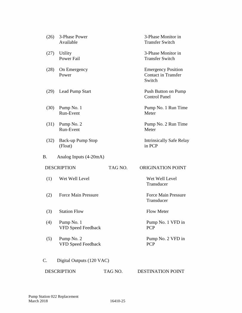
Pump Station 022 Replacement
March 2018 16410-25
(26) 3-Phase Power 3-Phase Monitor in
Available Transfer Switch
(27) Utility 3-Phase Monitor in
Power Fail Transfer Switch
(28) On Emergency Emergency Position
Power Contact in Transfer
Switch
(29) Lead Pump Start Push Button on Pump
Control Panel
(30) Pump No. 1 Pump No. 1 Run Time
Run-Event Meter
(31) Pump No. 2 Pump No. 2 Run Time
Run-Event Meter
(32) Back-up Pump Stop Intrinsically Safe Relay
(Float) in PCP
B. Analog Inputs (4-20mA)
DESCRIPTION TAG NO. ORIGINATION POINT
(1) Wet Well Level Wet Well Level
Transducer
(2) Force Main Pressure Force Main Pressure
Transducer
(3) Station Flow Flow Meter
(4) Pump No. 1 Pump No. 1 VFD in
VFD Speed Feedback PCP
(5) Pump No. 2 Pump No. 2 VFD in
VFD Speed Feedback PCP
C. Digital Outputs (120 VAC)
DESCRIPTION TAG NO. DESTINATION POINT
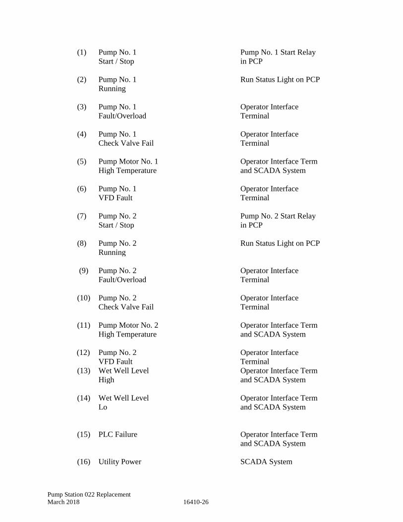
Pump Station 022 Replacement
March 2018 16410-26
(1) Pump No. 1 Pump No. 1 Start Relay
Start / Stop in PCP
(2) Pump No. 1 Run Status Light on PCP
Running
(3) Pump No. 1 Operator Interface
Fault/Overload Terminal
(4) Pump No. 1 Operator Interface
Check Valve Fail Terminal
(5) Pump Motor No. 1 Operator Interface Term
High Temperature and SCADA System
(6) Pump No. 1 Operator Interface
VFD Fault Terminal
(7) Pump No. 2 Pump No. 2 Start Relay
Start / Stop in PCP
(8) Pump No. 2 Run Status Light on PCP
Running
(9) Pump No. 2 Operator Interface
Fault/Overload Terminal
(10) Pump No. 2 Operator Interface
Check Valve Fail Terminal
(11) Pump Motor No. 2 Operator Interface Term
High Temperature and SCADA System
(12) Pump No. 2 Operator Interface
VFD Fault Terminal
(13) Wet Well Level Operator Interface Term
High and SCADA System
(14) Wet Well Level Operator Interface Term
Lo and SCADA System
(15) PLC Failure Operator Interface Term
and SCADA System
(16) Utility Power SCADA System
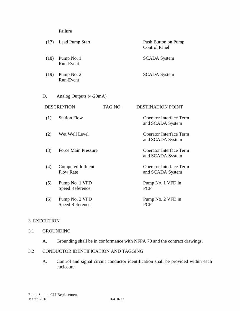
Pump Station 022 Replacement
March 2018 16410-27
Failure
(17) Lead Pump Start Push Button on Pump
Control Panel
(18) Pump No. 1 SCADA System
Run-Event
(19) Pump No. 2 SCADA System
Run-Event
D. Analog Outputs (4-20mA)
DESCRIPTION TAG NO. DESTINATION POINT
(1) Station Flow Operator Interface Term
and SCADA System
(2) Wet Well Level Operator Interface Term
and SCADA System
(3) Force Main Pressure Operator Interface Term
and SCADA System
(4) Computed Influent
Flow Rate
Operator Interface Term
and SCADA System
(5) Pump No. 1 VFD Pump No. 1 VFD in
Speed Reference PCP
(6) Pump No. 2 VFD Pump No. 2 VFD in
Speed Reference PCP
3. EXECUTION
3.1 GROUNDING
A. Grounding shall be in conformance with NFPA 70 and the contract drawings.
3.2 CONDUCTOR IDENTIFICATION AND TAGGING
A. Control and signal circuit conductor identification shall be provided within each
enclosure.
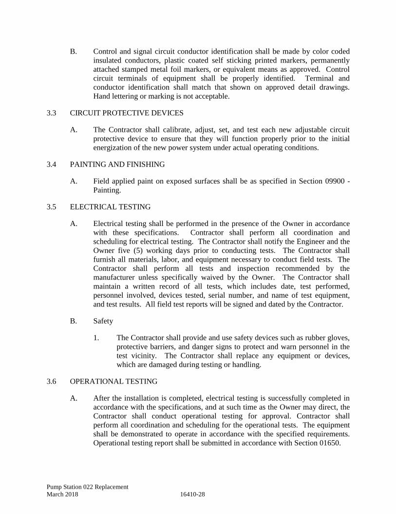
Pump Station 022 Replacement
March 2018 16410-28
B. Control and signal circuit conductor identification shall be made by color coded
insulated conductors, plastic coated self sticking printed markers, permanently
attached stamped metal foil markers, or equivalent means as approved. Control
circuit terminals of equipment shall be properly identified. Terminal and
conductor identification shall match that shown on approved detail drawings.
Hand lettering or marking is not acceptable.
3.3 CIRCUIT PROTECTIVE DEVICES
A. The Contractor shall calibrate, adjust, set, and test each new adjustable circuit
protective device to ensure that they will function properly prior to the initial
energization of the new power system under actual operating conditions.
3.4 PAINTING AND FINISHING
A. Field applied paint on exposed surfaces shall be as specified in Section 09900 -
Painting.
3.5 ELECTRICAL TESTING
A. Electrical testing shall be performed in the presence of the Owner in accordance
with these specifications. Contractor shall perform all coordination and
scheduling for electrical testing. The Contractor shall notify the Engineer and the
Owner five (5) working days prior to conducting tests. The Contractor shall
furnish all materials, labor, and equipment necessary to conduct field tests. The
Contractor shall perform all tests and inspection recommended by the
manufacturer unless specifically waived by the Owner. The Contractor shall
maintain a written record of all tests, which includes date, test performed,
personnel involved, devices tested, serial number, and name of test equipment,
and test results. All field test reports will be signed and dated by the Contractor.
B. Safety
1. The Contractor shall provide and use safety devices such as rubber gloves,
protective barriers, and danger signs to protect and warn personnel in the
test vicinity. The Contractor shall replace any equipment or devices,
which are damaged during testing or handling.
3.6 OPERATIONAL TESTING
A. After the installation is completed, electrical testing is successfully completed in
accordance with the specifications, and at such time as the Owner may direct, the
Contractor shall conduct operational testing for approval. Contractor shall
perform all coordination and scheduling for the operational tests. The equipment
shall be demonstrated to operate in accordance with the specified requirements.
Operational testing report shall be submitted in accordance with Section 01650.
Pump Station 022 Replacement
March 2018 16410-29
3.7 FIELD SERVICE
A. Onsite Training
1. The Contractor shall conduct a training course for the operating staff as
designated by the Owner. Contractor shall perform all coordination and
scheduling for training. The training period shall consist of a total of 12
hours of normal working time and shall start after the system is
functionally completed but prior to acceptance. Training shall include two
sessions to train the City’s operating staff. The course instruction shall
cover pertinent points involved in operating, starting, stopping, servicing
the equipment, as well as all major elements of the operation and
maintenance manuals. Additionally, the course instructions shall
demonstrate all routine maintenance operations.
B. Installation Engineer
1. After delivery of the equipment, the Contractor shall furnish one or more
field engineers, regularly employed by the equipment manufacturer to
supervise the installation of equipment, assist in the performance of the
onsite tests, oversee initial operations, and instruct personnel as to the
operational and maintenance features of the equipment.
C. Additionally, the Contractor shall coordinate visits from representatives for the
sewage pump and motors, VFD, Pump Controls and SCADA systems to ensure
that all the systems will work properly in concert. Visits from all these
representatives shall be coordinated twice; once at startup (operational testing),
and a second time to check operation after startup (final acceptance testing).
3.8 ACCEPTANCE
A. Final acceptance of the facility shall be in accordance with Section 01650.
END OF SECTION

Pump Station 022 Replacement
March 2018 16410-30
This Page Intentionally Left Blank
Pump Station 022 Replacement
March 2018 16440-1
SECTION 16440 - DISCONNECT SWITCHES
1. GENERAL
1.1 SUMMARY
A. Scope: Extent of disconnect switch work is indicated on the drawings and schedules,
by the requirements of this Section, and Section 16010, "Electrical Basic
Requirements".
B. Types: Types of disconnect switches covered by this Section include the following:
1. Enclosed, heavy duty non-fused switches.
2. Enclosed, heavy duty fusible switches.
1.2 QUALITY ASSURANCE
A. National Electrical Manufacturers Association (NEMA): Provide switches
conforming to NEMA KS 1, "Enclosed Switches".
B. NEMA: Construct enclosures conforming to NEMA 250, "Enclosures for Electrical
Equipment (1000 Volts Maximum)".
C. National Fire Protection Association (NFPA): Conform to NFPA 70, "National
Electrical Code", for installation and minimum fusing requirements.
D. Underwriters Laboratories, Inc. (UL): Manufacture switches conforming to the
requirements of UL 98, "Enclosed and Dead-Front Switches".
1. Provide switches listed and labeled by UL.
2. Provide fuse holders conforming to UL 512, "Fuseholders".
3. Provide cabinets conforming to UL 50, "Cabinets and Boxes".
1.3 SUBMITTALS
A. Product Data: For each switch provided on this project, furnish the manufacturer's
published technical data, drawings, dimensions, and capacities.
B. Submit shop drawings 30-days after date of notice to proceed.
2. PRODUCTS
2.1 MANUFACTURERS
Square D, General Electric, Cutler Hammer, or approved equal.
Pump Station 022 Replacement
March 2018 16440-2
2.2 SWITCHES
A. General: Provide individually enclosed air-break switches as indicated and scheduled
on the drawings, with all current-carrying parts enclosed and manually operable by
means of external handles. Switches shall be heavy duty (HD) type, ampere and
horsepower rated.
Provide cartridge enclosed fuses and rejection fuse holders when fused switches are
indicated.
Provide NEMA 1 enclosure for indoors, NEMA 3R enclosure for outdoors, or as
indicated on the drawings.
B. Ratings: Conform to NEMA KS 1 for voltage and horsepower ratings.
1. Voltages shall be 240 or 600 determined by the circuit voltage.
C. Switching Action: Provide quick-make, quick-break type switch action.
D. Construction: All current carrying parts shall be high conductivity copper, with
heating ratings conforming to UL 98.
1. Provide silver tungsten or silver-plated copper contacts.
2. Provide fuse holders of the rejection type, sized for fuses scheduled.
3. Switches shall have defeatable door interlocks that prevent the door from
opening when the operating handle is in the "on" position.
4. Switches shall have handles whose positions are easily recognizable and are
padlockable in the "on" or "off" position.
2.3 FUSES
A. General: Provide fuses that conform to UL 198C, 198D, and 198E. Provide fuses of
the sizes noted on the drawings.
1. Current-limiting fuses shall be installed in lieu of regular fuses where the
fault current exceeds 10,000 RMS amperes.
2. Unless otherwise specified, fuses for use with switches rated 600 amperes
and less shall be UL Class RK-5. Class RK-5 fuses shall be dual element
type with minimum time-delay of ten seconds at 500 percent of rating.
3. Provide one complete set of fuses installed for all switches requiring fuses.
Provide ten percent spare fuses or three (whichever is greater) of each size
and type installed. The spare fuses shall be delivered in the original boxes.
Pump Station 022 Replacement
March 2018 16440-3
3. EXECUTION
3.1 INSTALLATION OF SWITCHES
A. General: Provide NEMA 1 disconnect switches for interior use and NEMA 3R for
exterior use.
B. Installation: Install switches in conformance with the manufacturer's requirements
and NFPA 70, paragraph, "Switches". Provide grounding in accordance with
NFPA 70.
END OF SECTION

Pump Station 022 Replacement
March 2018 16440-4
This Page Intentionally Left Blank
Pump Station 022 Replacement
March 2018 16450-1
SECTION 16450 - GROUNDING
1. GENERAL
1.1 SUMMARY
A. Scope: Extent of the grounding work required is indicated on drawings, by the
requirements of this Section, and Section 16010, "Electrical Basic Requirements".
B. Provide grounding in accordance with NEC as a minimum. Additional grounding
requirements shall be as specified or indicated on drawings.
C. Related Sections: Refer to other Division 16 Sections for grounding and testing.
1.2 QUALITY ASSURANCE
A. American National Standards Institute (ANSI): Comply with the requirements of:
1. C2 National Electric Safety Code.
B. American Society for Testing and Materials (ASTM): Comply with the
requirements of:
1. B 1 Standard Specification for Hard-Drawn Copper Wire
2. B 2 Standard Specification for Medium-Hard-Drawn Copper Wire
3. B 3 Standard Specification for Soft or Annealed Copper Wire
4. B 8 Standard Specification for Concentric-Lay-Stranded Copper
Conductors, Hard, Medium-Hard, or Soft
5. B 228 Standard Specification for Concentric-Lay-Stranded Copper-Clad
Steel Conductors
C. Institute of Electrical and Electronics Engineers (IEEE): Comply with the
following standards which apply to the grounding of electrical systems:
1. Recommended Practice for Grounding of Industrial and Commercial
Power Systems
2. Recommended Practice for Electric Power Systems in Commercial
Buildings
D. National Fire Protection Association (NFPA): Comply with the requirements of
NFPA 70, “National Electrical Code" for the grounding of electrical systems.
E. Underwriters Laboratories, Inc. (UL): Provide material and installation
conforming to the following standards:
1. Grounding and Bonding Equipment
2. Service Equipment
Pump Station 022 Replacement
March 2018 16450-2
F. UL Labels: Provide grounding electrodes and connectors, which are UL, listed and
labeled.
1.3 SUBMITTALS
A. Product Data: Submit manufacturer's data on conductors, grounding electrodes,
ground clamps, and exothermic welding devices.
B. Submit shop drawings 30-days after date of notice to proceed.
2. PRODUCTS
2.1 GROUND RODS
A. Ground rods shall be copper clad steel, 10 feet in length and ¾-inch in diameter.
2.2 GROUNDING ELECTRODE CONDUCTORS
A. Grounding electrode conductors shall be bare copper sized in accordance with NEC
Table 250-66.
2.3 EQUIPMENT GROUNDING CONDUCTORS
A. Equipment grounding conductors in raceways shall be copper with green insulation,
sized in accordance with NEC 250-122. Bare copper grounding conductors will be
acceptable in underground outside raceways.
2.4 GROUND CONNECTIONS
A. Ground connections shall be exothermic type cadweld or thermoweld, when direct
buried.
3. EXECUTION
3.1 INSPECTION
A. General: Examine all areas and conditions under which electrical grounding
connections are to be made. Do not proceed with the grounding work until such
unsatisfactory conditions have been corrected.
3.2 GROUNDING BUILDING SERVICE
A. General: Supplement the grounded neutral of the distribution system with an
equipment grounding system to properly safeguard equipment and personnel. The
system shall, as a minimum, comply with NFPA 70. Where the drawings or
Pump Station 022 Replacement
March 2018 16450-3
specifications exceed the requirements of NFPA 70, the drawings or specifications
take preference.
B. Building Steel: Ground the electrical service to the steel frame of the building.
C. Common Ground Bus: Connect the system neutral ground and the equipment ground
system to the common ground bus as indicated on the drawings. Where the
connection is not shown, provide connection as required by NFPA 70.
3.3 GENERAL
A. Install equipment grounding conductors in all raceways containing conductors having
100 volts or more to ground.
B. Ground all metallic enclosures.
C. The ground resistance of any "made" electrode shall be measured by an earth megger
device and it shall be 25 ohms or less as per NEC 250.
D. A copy of the service ground resistance test shall be sent to the Owner and Owner
representative.
END OF SECTION

Pump Station 022 Replacement
March 2018 16450-4
This Page Intentionally Left Blank
Pump Station 022 Replacement
March 2018 16470-1
SECTION 16470 - PANELBOARDS
1. GENERAL
1.1 SUMMARY
A. Scope: Extent of panelboard work is indicated on the drawings and schedules, by the
requirements of this Section, and Section 16010, "Electrical Basic Requirements".
B. Types: Types of panelboards and enclosures covered under this Section include the
following:
1. Panelboards with automatic circuit breakers.
1.2 QUALITY ASSURANCE
A. National Electrical Manufacturers Association (NEMA):
1. AB 1 Molded Case Circuit Breakers and Molded Case Switches
2. KS 1 Enclosed Switches
3. PB 1 Panelboards
B. National Fire Protection Association (NFPA): Conform to the requirements of
NFPA 70, "National Electrical Code".
C. Underwriters Laboratories, Inc. (UL): Construct panelboards in conformance with
the following UL publications:
1. UL 50 Cabinets and Boxes
2. UL 67 Panelboards
3. UL 310 Electrical Quick-Connect Terminals
4. UL 486A Wire Connectors and Soldering Lugs for Use with Copper
Conductors
5. UL 486B Wire Connectors for Use with Aluminum Conductors
6. UL 489 Molded-Case Circuit Breakers and Circuit-Breaker Enclosures
7. UL 512 Fuseholders
8. UL 943 Ground-Fault Circuit Interrupters
9. UL 1053 Ground-Fault Sensing and Relaying Equipment
Pump Station 022 Replacement
March 2018 16470-2
1.3 SUBMITTALS
Submit the following:
A. Product Data: Submit manufacturer's data on panelboards including:
1. Manufacturer's materials specifications.
2. Certification for compliance with referenced standards.
3. Enclosed type.
4. Breaker types.
5. Bus ampacity.
6. Voltage rating.
B. Submit shop drawings 30-days after date of notice to proceed.
2. PRODUCTS
2.1 MANUFACTURERS
A. Square D, General Electric, Cutler Hammer, or approved equal.
2.2 PANELBOARDS
A. Buses: Provide panelboards with buses constructed of solid copper, minimum
conductivity 98 percent and rectangular shape.
1. Mechanically mount and brace buses in conformance with UL 67.
2. Provide solderless lugs for copper or aluminum cable.
3. Provide ampacity as scheduled on the drawings.
B. Grounding Bus: Provide bare, uninsulated copper, factory installed grounding bus
with ampacity equal to the main bus.
1. Provide copper pressure connected terminations.
C. Bus sequencing: Provide bus bar connections to branch circuits of the sequenced
phased type.
1. Mount in accordance with UL 67.
2. Provide numbered terminals.
3. Provide pressure connectors, copper.
D. Service Equipment: Panelboards identified for use as service equipment shall be
labeled.
Pump Station 022 Replacement
March 2018 16470-3
E. Spaces: Where words similar to "space", "space only", "future space" or similar
wording are used on the drawings and panel schedules, provide bus space for future
overcurrent devices.
1. Extend buses full size.
2. Brace and insulate bus in accordance with UL 67.
3. Provide bolted connections for future overcurrent devices.
F. Enclosures: Construct in accordance with UL 50 except modify as hereinafter
specified.
1. Construct of minimum 16-gauge galvanized steel.
2. Conform to UL 67 for additional enclosure requirements.
G. Knockouts: Provide multiple knockouts not fewer than 1.5 times the number of bus
circuits.
H. Painting: In addition to galvanizing or priming coat, all inside and outside surfaces
of trim and doors shall be given a factory finish coat of gray paint. Recessed boxes
and surface boxes in transformer vaults, switchgear rooms and electrical closets may
be galvanized or painted as described above.
I. Directories: Provide waterproof, white cardboard stock, factory printed
directories with a clear plastic directory cover and metal frame attached to the
panel door. Directory information shall be typed.
J. Wiring Space: Conform to the requirements of UL 67. Feed-through gutters not
permitted.
K. Conform to NFPA 70 for maximum gutter fill.
L. Conform to UL 67 for minimum width of gutter and wire bending space.
M. Manufacturer: Panelboard, back-box and front plate shall be the product of one
manufacturer. Factory fit components before shipment.
N. Enclosure Type: Provide enclosure type in conformance with UL 50 and NEMA
PB 1.
O. Front Plates: Provide removable front plates of the dead-front type with
removable, adjustable cadmium plated trim clamps, and flush hinged enclosure
door.
2.3 LOAD CENTERS ARE NOT ACCEPTABLE.
Pump Station 022 Replacement
March 2018 16470-4
2.4 CIRCUIT BREAKERS
A. Circuit Protective Devices: Provide molded case circuit breakers conforming to UL
489 and NEMA AB 1; voltage and poles as scheduled:
1. Provide interrupting ratings as schedules.
2. Provide common trip mechanisms for multi-pole breakers.
3. Provide instantaneous automatic trips conforming to NEMA AB 1.
4. Provide breakers with adjustable trip settings as scheduled.
5. Breakers shall be bolt-on type, factory assembled.
6. Stab-in circuit breaker types are not acceptable.
7. Provide branch circuit arrangement as scheduled.
8. Provide quick-make and quick-break mechanism.
3. EXECUTION
3.1 INSTALLATION
A. Install panelboards in conformance with NEMA PB 1, and NFPA 70.
B. Lug Torquing: Torque lug screws in accordance with UL 486A for copper
conductors. Install connectors, lugs, neutral bus, and other field installed
components in accordance with manufacturer's published literature.
C. Wiring: Refer to drawings for feeder and branch circuit wiring.
1. Verify gutter size conforms to wire bending space requirements of NFPA 70
and UL 67.
2. Wire wrap branch circuit in gutters after installation. Use approved wire ties.
3. Verify maximum gutter fill to conform with NFPA 70 and UL 67.
4. Verify bolted circuit breaker connection lugs conforming to shop drawings.
5. Verify breaker size, trip setting, and breaker type in conformance with
schedules.
Complete typewritten panelboard circuit directory prior to project acceptance.
D. Only wires made of the conductor material for which the panelboard terminals have
been marked shall be used.
Pump Station 022 Replacement
March 2018 16470-5
3.2 GROUNDING
A. Provide equipment grounding connections for panelboards as indicated on drawings
or schedules.
1. Conform to the requirements of NFPA 70.
2. Install lugs and ground connectors in conformance with UL 486A and UL
486B.
3.3 ADJUSTABLE TRIP SETTINGS
A. Verify factory settings for adjustable trip breakers.
B. Field adjust in conformance with manufacturer's recommendations, if necessary.
3.4 NAMEPLATES
A. Identification: Provide rigid engraved plastic nameplates conforming to the
requirements of Section 16195, "Electrical Identification", for each panelboard.
3.5 INSPECTION AND TESTS
A. Check circuit breakers and switches for proper mounting, conductor size, and feeder
designation.
B. Operate circuit breakers and switches to ensure smooth operation.
C. Inspect the cases of molded case circuit breakers for cracks or other defects.
D. Measure the insulation resistance of the panelboard bus system using a 500VDC
megohm-meter.
E. Measure both phase-to-phase and phase-to-ground resistance. The minimum
acceptable resistance shall be two megohms.
END OF SECTION

Pump Station 022 Replacement
March 2018 16470-6
This Page Intentionally Left Blank
Pump Station 022 Replacement
March 2018 16475-1
SECTION 16475 - MOLDED CASE CIRCUIT BREAKERS (MCCB)
1. GENERAL
1.1 REFERENCES
NEMA Publication AB 1 Molded Case Circuit Breakers.
1.2 DESCRIPTION
This section applies to all MCCB whether individually enclosed, group mounted, or part
of other equipment.
1.3 SUBMITTALS
Provide submittals in accordance 01300 – Submittals. Submit shop drawings 30-days
after date of notice to proceed.
2. PRODUCTS
2.1 GENERAL
A. MCCB shall be bolt-on type with ratings and special features as scheduled.
B. Trips
1. Trips shall be thermal magnetic with inverse time delay and instantaneous
time-current characteristics.
2. Motor circuit protectors (MCP) having magnetic only trips shall be
provided where indicated. MCP's used with high efficiency motors shall
be capable of carrying the transient inrush current without having to be set
at more than 13 times full load current.
3. When indicated on the drawings, trips shall be solid state. They shall be
field adjustable with characteristics as scheduled.
4. MCCB used outdoors shall have ambient compensating trips.
C. MCCB used for switching lights shall be rated for switching duty.
2.2 MCCB SUBMITTAL
Industrial grade MCCB data
2.3 VOLTAGE
MCCBs of 240 volts or less may be commercial grade MCCB (quick-lag, "q-line").
2.4 MANUFACTURERS
Manufacturer shall be Square D, General Electric, or Cutler-Hammer.
Pump Station 022 Replacement
March 2018 16475-2
3. EXECUTION
3.1 SPARE FUSES
For integrally fused MCCB, provide three spare fuses for each panelboard or individually
enclosed circuit breaker of each size and type used.
END OF SECTION
Pump Station 022 Replacement
March 2018 16482-1
SECTION 16482 - MOTOR STARTERS
1. GENERAL
1.1 SUMMARY
A. Scope: Extent of motor starter work is indicated on the drawings and schedules, by
the requirements of this Section, and Section 16010, "Electrical Basic Requirements".
B. Types: Types of motor starters specified in this Section include the following:
1. Manual.
2. Magnetic full voltage.
C. Other Divisions: Refer to Division 15 sections for the following work:
1. Starters furnished as an integral part of mechanical equipment.
D. Related Sections: Refer to the sections of Division 16 for the following:
1. Switches and Disconnects.
1.2 QUALITY ASSURANCE
A. National Electrical Manufacturers Association (NEMA): Provide starters and
controllers conforming to the following NEMA standards:
1. ICS 2 Standards for Industrial Control Devices, Controllers and Assemblies.
2. Enclosures for Electrical Equipment (1,000 Volts Maximum).
3. Underwriters Laboratories, Inc. (UL): Provide fuses conforming to the
following:
4. 198D Class K Fuses.
5. 198E Class R Fuses.
6. 198G Fuses for Supplementary Overcurrent Protection.
7. Provide starters conforming to UL 508 "Industrial Control Equipment".
8. Provide motor starters and components UL listed and labeled.
1.3 SUBMITTALS
A. Product Data: Submit manufacturer's data on all motor starters indicated or
scheduled. For each starter show the following:
1. Type.
2. NEMA size.
3. Enclosure.
4. Pilot lights.
5. Selector switches.
6. Disconnect switches.
Pump Station 022 Replacement
March 2018 16482-2
7. Circuit breakers.
8. Instruments.
9. Control transformer.
B. Submit shop drawings 30-days after date of notice to proceed.
2. PRODUCTS
2.1 STARTERS: GENERAL
A. Starters: For each motor scheduled or indicated and not provided with integral
starter, install a motor starter, unless otherwise indicated on Drawings.
B. Types: Provide types indicated and coordinate each starter in motor characteristics
and control requirements.
C. Contacts: Equip each starter with contacts to break each ungrounded line to the
motor.
D. Overload Trips: Provide thermal overload devices, in each phase, to open all contacts
simultaneously. Equip starters with a manual thermal overload trip reset button. Size
overload trips to match motor nameplate amperes, in accordance with the
requirements of National Fire Protection Association (NFPA) 70, "National Electrical
Code".
E. Enclosures: Unless otherwise specified or indicated, provide each starter in a NEMA
Type 1 general purpose enclosure.
F. Construction: Design and construct starters as follows:
1. For each starter provide doors arranged for padlocking and with a cardholder
for starter identification. Provide an external reset mechanism, "start-stop"
pushbuttons for manually controlled motors and hand-off-automatic ("H-O-
A") switch for automatically started motors. Provide green "stop", red "run"
pilot lights of the heavy duty oil-tight diode or resistor type.
2. Make connections to the selector switch such that only the manual
automatic regulatory control devices will be bypassed when the switch is
in the "hand" position. Control safeties cannot be bypassed.
3. All safety control devices, such as low and high pressure cutouts, high
temperature cutouts, and motor overload protectors, shall be connected in
the motor control circuit in both the "hand" and the "automatic" positions.
4. Control circuit connections to any "hand-off-automatic" selector switch or
to more than one automatic regulatory control device shall be made in
accordance with an indicated, or a manufacturer's approved, wiring
diagram.
5. Provide the selector switch with means for locking in any position.
Pump Station 022 Replacement
March 2018 16482-3
6. The controller disconnecting means shall be capable of being locked in the
"open" position. For each motor not in sight of the controller, provide a
manually operated, nonfused switch which will disconnect the motor from
the source and which is placed within sight of the motor location.
7. Overload protective devices shall give adequate protection to the motor
windings, be of the thermal inverse-time-limit type, and include a manual-
reset type pushbutton on the outside of the motor controller case.
8. Provide each magnetic starter with a control transformer located within the
starter enclosure and with wiring extended to associated accessories and to
terminal boards for remotely located accessories.
2.2 MAGNETIC FULL VOLTAGE NON-REVERSING STARTERS
A. General: Conform to the requirements of paragraph, "Starters: General".
B. Type: Provide starters of the full voltage magnetic across-the-line type, with
undervoltage release and auxiliary contacts indicated or specified, and of sizes
indicated on the drawings.
C. Single Phase Protection: Provide single phase protection in each magnetic starter.
2.3 MANUAL STARTERS
A. General: Conform to the requirements of "Starters: General", article, of this Section.
B. Maximum Size: Use manual starters for motors less than 1/2 horsepower unless
otherwise indicated.
C. Type: Provide manual starters as follows:
1. Manually operated quick-make, quick-break toggle mechanism.
2. One piece melting alloy thermal switch.
3. Double break silver alloy contacts.
4. Red run pilot light.
5. Arrange for padlocking "Off".
6. Horsepower rate per NEMA standards.
7. NEMA Type 1 general purpose enclosure unless otherwise indicated or
specified.
Pump Station 022 Replacement
March 2018 16482-4
3. EXECUTION
3.1 INSTALLATION OF STARTERS
A. Standard: Install motor starter where indicated, in accordance with manufacturer's
written instructions and in conformance with NFPA 70 and NEMA standards.
B. Coordination: Coordinate starter accessories such as pushbutton switches or H-O-
A switches and auxiliary contacts with automatic control sequencing
requirements.
C. Mounting: Bolt wall mounted panels to walls or mount on lightweight structural
steel bolted to the wall. Mount floor supported starters on structural steel welded
frames of 1-1/2-inch by 1-1/2-inch by 1/4-inch welded steel, two vertical posts
with crossarm, and bolt to the floor. Construct feet of 6-inch by 6-inch by 3/8-
inch thick steel plate bolted to the floor.
D. Location: Locate starters within sight of their associated motors. Where starter is
not within sight of the motor, provide a heavy duty disconnect switch at the
motor.
E. Fuses: Install fuses in fused disconnect switches. Size fuses in conformance with
NFPA 70, and UL 198D, 198E, and 198G listed.
END OF SECTION
Pump Station 022 Replacement
March 2018 16510-1
SECTION 16510 – LED LIGHTING FIXTURES
1. GENERAL
1.1 SUMMARY
A. Scope: Extent of lighting fixture work is indicated on drawings and schedules, by
requirements of this Section, and Section 16010, "Electrical Basic Requirements".
1.2 QUALITY ASSURANCE
A. Manufacturers: Provide products of firms regularly engaged in the manufacture of
lighting fixtures of types and ratings required, whose products have been in
satisfactory use in similar service for not less than two (5) years.
B. The lighting fixtures have been scheduled on the drawings by manufacturer and
catalog number. This information shall set the required fixture performance and level
of quality. Fixture performance and quality specified elsewhere in this specification
shall rule, if there is an implied conflict between the specification and the catalog
number used. Fixtures of equal performance and quality as judged by the Owner will
be accepted.
C. National Fire Protection Association (NFPA): Comply with NFPA 70, "National
Electrical Code", as applicable to construction and installation of interior building
lighting fixtures and emergency lighting.
D. Underwriters Laboratories, inc. (UL): Provide interior and exterior lighting fixtures
which have been UL, listed, and labeled.
1.3 SUBMITTALS
Submit the following:
A. Shop Drawings:
a. Submit the following information for each type of lighting fixture designated
on the LIGHTING FIXTURE SCHEDULE, arranged in order of lighting
fixture designation.
b. Material and construction details, include information on housing and optics
system.
c. Physical dimensions and description.
d. Wiring schematic and connection diagram.
e. Installation details.
f. Energy efficiency data.
Pump Station 022 Replacement
March 2018 16510-2
g. Photometric data based on laboratory tests complying with IES Lighting
Measurements testing and calculation guides.
h. US DOE LED Lighting Facts label, and IES L70 rated life.
i. Submit fixture shop drawings in booklet form with separate sheet for each
fixture, assembled in order of luminaire "Type" designation with proposed
fixture and accessories clearly indicated on each sheet.
j. Submit shop drawings 30-days after date of notice to proceed.
2. PRODUCTS
2.1 GENERAL
A. Lighting Fixture Requirements: Provide fixtures, which meet the requirements of
these specifications and the project drawings.
B. General Requirements: Provide lighting fixtures of sizes, types, and ratings
indicated.
2.2 LED LIGHT FIXTURES
A. General:
a. LED light fixtures shall be in accordance with IES, NFPA, UL, as shown on
the drawings, and as specified.
b. LED light fixtures shall be Reduction of Hazardous Substances (RoHS)-
compliant.
c. LED drivers shall include the following features unless otherwise indicated:
i. Minimum efficiency: 85% at full load.
ii. Minimum Operating Ambient Temperature: Interior, -20˚ C. (-4˚
F.); Exterior, -40˚ C. (-40˚ F.)
iii. Input Voltage: 120V (±10%) at 60 Hz.
iv. Integral short circuit, open circuit, and overload protection.
v. Power Factor: ≥ 0.95.
vi. Total Harmonic Distortion: ≤ 20%.
vii. Comply with FCC 47 CFR Part 15.
d. LED modules shall include the following features unless otherwise indicated:
i. Comply with IES LM-79 and LM-80 requirements.
ii. Minimum CRI 80 and color temperature 4000˚ K unless otherwise
specified in LIGHTING FIXTURE SCHEDULE.
iii. Minimum Rated Life: 50,000 hours per IES L70.
iv. Light output lumens as indicated in the LIGHTING FIXTURE
SCHEDULE.
Pump Station 022 Replacement
March 2018 16510-3
3. EXECUTION
3.1 INSTALLATION
Setting and Securing: Set lighting fixtures plumb, square, and level with ceiling and walls, in
alignment with adjacent lighting fixtures, and secure in accordance with manufacturers'
directions and approved shop drawings. Conform to the requirements of NFPA 70.
A. Mounting: Mounting heights specified are indicated to the bottom of the fixture for
suspended and ceiling-mounted fixtures and to center of fixture for wall-mounted
fixtures. Obtain approval of the exact mounting for lighting fixtures on the job
before installation is commenced and, where applicable, after coordinating with the
type, style, and pattern of the ceiling being installed.
B. Coordination: Coordinate with other trades as appropriate to properly interface
installation of lighting fixtures with other work.
C. Grounding: Ground non-current-carrying parts of electrical equipment. Where the
copper grounding conductor is connected to a metal other than copper, provide
specially treated or lined connectors suitable for this purpose.
3.2 ADJUST AND CLEAN
A. Clean: Clean lighting fixtures of dirt and debris upon completion of installation.
B. Protection: Protect installed fixtures from damage during remainder of construction
period.
C. Adjust: Adjust light fixtures as directed by the Owner.
3.3 FIELD QUALITY CONTROL
A. Tests: Upon completion of installation of lighting fixtures, and after building circuits
have been energized, apply electric energy to demonstrate capacity and compliance
with requirements. Where possible, correct malfunctioning units at site, then retest to
demonstrate compliance; otherwise, remove and replace with new units, and proceed
with retesting.
B. At completion of project, replace all defective components of the lighting fixtures
at no cost to the Owner.
END OF SECTION

Pump Station 022 Replacement
March 2018 16510-4
This Page Intentionally Left Blank
Pump Station 022 Replacement
March 2018 16690-1
SECTION 16690 - VARIABLE FREQUENCY DRIVES
PART 1 - GENERAL
1.01 WORK INCLUDED
A. Scope of Work:
1. The Contractor shall furnish all labor, materials, equipment, and incidentals
required to provide, install, test, and place in operation the Variable
Frequency Drives (VFD’s) shown on the drawings and specified.
2. The Systems House supplying the VFD’s and related equipment shall be
responsible for coordination of the VFD’s with the pump motors,
RTU/SCADA, and control system and as shown on the drawings and
specified in Division 16.
3. Overall system responsibility shall include programming, calibration, field
testing, startup training, and successful operation of the equipment.
4. The VFD shall be coordinated with the Pump System Manufacturer and MCC
provider to ensure compatibility and operation with the pump and pump
motor for sewage pumping application. The VFD shall be shipped to the
motor control center (mcc) manufacturer for installation in the mcc. The VFD
shall have a history of operating the pump motor and pumping system.
B. Related Work:
1. Section 11330, Submersible Sewage Pumps
2. Section 16010, Electrical Basic Requirements
3. Section 16410, Pump Control Panel
C. Submit shop drawings 30-days after date of notice to proceed.
1.02 SYSTEM DESCRIPTION
A. The VFD’s shall start, stop, and vary the speed of the pumps in response to the
control system.
B. The VFD’s shall be capable of automatic and manual operation. Automatic speed
setting shall be from a proportional 4-20mA signal, manual control shall be accessible
via a speed potentiometer installed on the VFD control panel door.
C. The VFD’s shall be capable of remote operation of all functions via terminal input
points. All normal operating functions, e.g., starting, stopping, manual/automatic
selection, speed control, and fault reset, shall be accessible from the control panel
door mounted operator interface controls and shall not require physical access to the
VFD itself.
Pump Station 022 Replacement
March 2018 16690-2
D. Each VFD system shall include surge suppressor, line reactor, input and output
isolation contactors, emi/rfi filters, forced air cooling, filtered air inlets, keypad,
indicating lights, HOA switch, run time meter, and fuse. Selection of bypass
operation shall be manual by-pass switch on the face of the VFD control panel.
E. The VFD’s shall be furnished with a self diagnostic software that can be monitored,
modified and parameters stored on a compact disc. Provide a copy of the
programming software and configuration settings on a compact disc. Provide cabling
between drive diagnostic port and a laptop computer.
H. All VFD’s shall be rated 15 HP, 240V, 3-Phase, compatible with the selected sewage
pump motor, and heavy duty rated.
I. All VFD’s shall have a remote keypad or Human Interface Module mounted on the
exterior of the panel and connected with factory provided cables.
PART 2 - PRODUCTS
2.01 MANUFACTURER REQUIREMENTS
A. Acceptable Manufacturers:
1. Square D
2. Allen-Bradley
3. Yaskawa
4. Cerus Industrial
5. Toshiba
B. Acceptable Sources:
1. The VFD Distributor shall have been engaged in the business of sales and
service of the VFD Manufacturer’s products for a period of not less than 5
years.
2. The VFD Distributor shall have at least 2 factory trained engineers on staff
who are experienced in VFD selection, application, and start-up. Combined
experience of the engineering staff with the accepted manufacturer's product
line shall not be less than 10 years.
3. The VFD Distributor shall maintain a warranty and service facility that is
recognized and approved by the VFD Manufacturer. This facility shall be
staffed with factory trained service technicians competent in the start-up,
trouble-shooting, and repair of the approved VFD.
a. On site repair service shall be available 24 hours per day, 365 days per
year.
b. The repair facility shall be capable of providing a technician on the
Pump Station 022 Replacement
March 2018 16690-3
owner’s site within two hours of a call for service.
c. The repair facility shall be located within a 100 miles radius of the job
site.
2.02 DRIVE CONSTRUCTION AND CAPACITIES
A. The VFD’s shall be Sinusoidal Pulse Width Modulated AC Inverter type, shall feature
digital control of all functions and EEPROM storage of both factory default and user
selectable parameters.
B. The VFD’s shall contain a door mounted keypad/LED display that allows user access
to all stored parameters, and provides operator interface for control of all drive
functions. In addition, keypad control shall be deselectable, allowing control of all
operational functions of the VFD’s via terminal input points.
C. The VFD’s shall be applied at manufacturers nameplated and advertised rating. Re-
nameplating VFD’s to indicate any rating in excess of the original ratings will not be
allowed.
D. The VFD’s shall be suitable for operation of the pump motors provided.
E. The VFD converter section shall utilize a 3 phase, full wave, diode bridge rectifier to
minimize the generation of noise on the power line and provide near unity power
factor over the entire speed range.
F. VFD’s that do not contain a DC bus link reactor must be provided with a separate 3
phase line reactor connected to the input side of the VFD. Separate Line Reactors
shall be horsepower rated and provide 5.5% impedance.
G. The VFD inverter section shall incorporate Insulated Gate Bipolar Transistors as the
power switching devices.
H. Overload Capability of the VFD’s shall not be less than 150% for 120 seconds, and
110% continuous.
I. The VFD’s shall be UL listed and labeled.
2.03 ENVIRONMENTAL CONDITIONS
A. The VFD enclosure shall meet NEMA 12 standards.
C. The VFD’s shall be capable of operation under any combination of the following
conditions without mechanical or electrical damage:
1. Ambient Temperature: -10 to 40 C (14 to 104F).
2. Relative Humidity: Less than 90% non condensing.
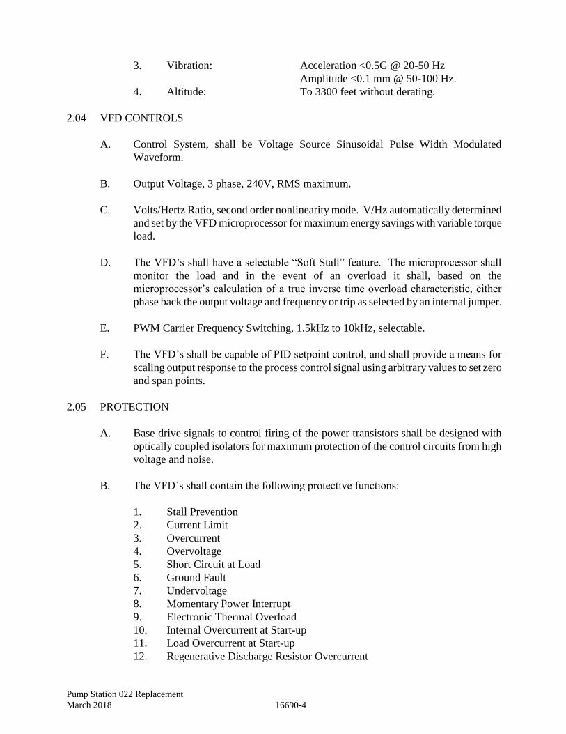
Pump Station 022 Replacement
March 2018 16690-4
3. Vibration: Acceleration <0.5G @ 20-50 Hz
Amplitude <0.1 mm @ 50-100 Hz.
4. Altitude: To 3300 feet without derating.
2.04 VFD CONTROLS
A. Control System, shall be Voltage Source Sinusoidal Pulse Width Modulated
Waveform.
B. Output Voltage, 3 phase, 240V, RMS maximum.
C. Volts/Hertz Ratio, second order nonlinearity mode. V/Hz automatically determined
and set by the VFD microprocessor for maximum energy savings with variable torque
load.
D. The VFD’s shall have a selectable “Soft Stall” feature. The microprocessor shall
monitor the load and in the event of an overload it shall, based on the
microprocessor’s calculation of a true inverse time overload characteristic, either
phase back the output voltage and frequency or trip as selected by an internal jumper.
E. PWM Carrier Frequency Switching, 1.5kHz to 10kHz, selectable.
F. The VFD’s shall be capable of PID setpoint control, and shall provide a means for
scaling output response to the process control signal using arbitrary values to set zero
and span points.
2.05 PROTECTION
A. Base drive signals to control firing of the power transistors shall be designed with
optically coupled isolators for maximum protection of the control circuits from high
voltage and noise.
B. The VFD’s shall contain the following protective functions:
1. Stall Prevention
2. Current Limit
3. Overcurrent
4. Overvoltage
5. Short Circuit at Load
6. Ground Fault
7. Undervoltage
8. Momentary Power Interrupt
9. Electronic Thermal Overload
10. Internal Overcurrent at Start-up
11. Load Overcurrent at Start-up
12. Regenerative Discharge Resistor Overcurrent
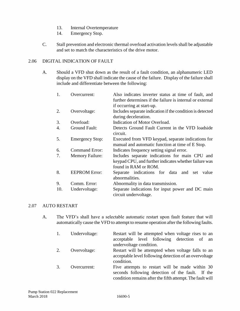
Pump Station 022 Replacement
March 2018 16690-5
13. Internal Overtemperature
14. Emergency Stop.
C. Stall prevention and electronic thermal overload activation levels shall be adjustable
and set to match the characteristics of the drive motor.
2.06 DIGITAL INDICATION OF FAULT
A. Should a VFD shut down as the result of a fault condition, an alphanumeric LED
display on the VFD shall indicate the cause of the failure. Display of the failure shall
include and differentiate between the following:
1. Overcurrent: Also indicates inverter status at time of fault, and
further determines if the failure is internal or external
if occurring at start-up.
2. Overvoltage: Includes separate indication if the condition is detected
during deceleration.
3. Overload: Indication of Motor Overload.
4. Ground Fault: Detects Ground Fault Current in the VFD loadside
circuit.
5. Emergency Stop: Executed from VFD keypad, separate indications for
manual and automatic function at time of E Stop.
6. Command Error: Indicates frequency setting signal error.
7. Memory Failure: Includes separate indications for main CPU and
keypad CPU, and further indicates whether failure was
found in RAM or ROM.
8. EEPROM Error: Separate indications for data and set value
abnormalities.
9. Comm. Error: Abnormality in data transmission.
10. Undervoltage: Separate indications for input power and DC main
circuit undervoltage.
2.07 AUTO RESTART
A. The VFD’s shall have a selectable automatic restart upon fault feature that will
automatically cause the VFD to attempt to resume operation after the following faults.
1. Undervoltage: Restart will be attempted when voltage rises to an
acceptable level following detection of an
undervoltage condition.
2. Overvoltage: Restart will be attempted when voltage falls to an
acceptable level following detection of an overvoltage
condition.
3. Overcurrent: Five attempts to restart will be made within 30
seconds following detection of the fault. If the
condition remains after the fifth attempt. The fault will
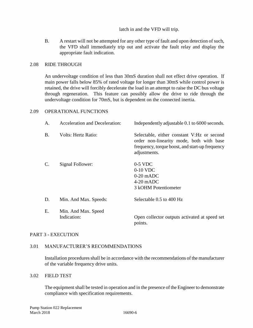
Pump Station 022 Replacement
March 2018 16690-6
latch in and the VFD will trip.
B. A restart will not be attempted for any other type of fault and upon detection of such,
the VFD shall immediately trip out and activate the fault relay and display the
appropriate fault indication.
2.08 RIDE THROUGH
An undervoltage condition of less than 30mS duration shall not effect drive operation. If
main power falls below 85% of rated voltage for longer than 30mS while control power is
retained, the drive will forcibly decelerate the load in an attempt to raise the DC bus voltage
through regeneration. This feature can possibly allow the drive to ride through the
undervoltage condition for 70mS, but is dependent on the connected inertia.
2.09 OPERATIONAL FUNCTIONS
A. Acceleration and Deceleration: Independently adjustable 0.1 to 6000 seconds.
B. Volts: Hertz Ratio: Selectable, either constant V:Hz or second
order non-linearity mode, both with base
frequency, torque boost, and start-up frequency
adjustments.
C. Signal Follower: 0-5 VDC
0-10 VDC
0-20 mADC
4-20 mADC
3 kOHM Potentiometer
D. Min. And Max. Speeds: Selectable 0.5 to 400 Hz
E. Min. And Max. Speed
Indication: Open collector outputs activated at speed set
points.
PART 3 - EXECUTION
3.01 MANUFACTURER’S RECOMMENDATIONS
Installation procedures shall be in accordance with the recommendations of the manufacturer
of the variable frequency drive units.
3.02 FIELD TEST
The equipment shall be tested in operation and in the presence of the Engineer to demonstrate
compliance with specification requirements.
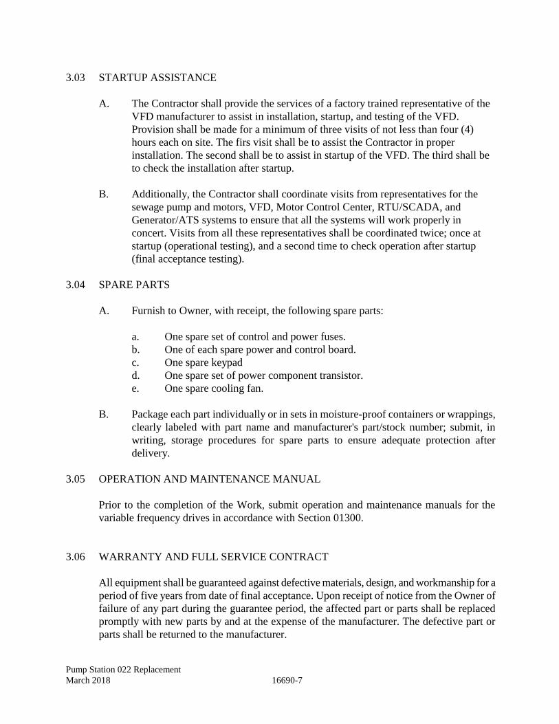
Pump Station 022 Replacement
March 2018 16690-7
3.03 STARTUP ASSISTANCE
A. The Contractor shall provide the services of a factory trained representative of the
VFD manufacturer to assist in installation, startup, and testing of the VFD.
Provision shall be made for a minimum of three visits of not less than four (4)
hours each on site. The firs visit shall be to assist the Contractor in proper
installation. The second shall be to assist in startup of the VFD. The third shall be
to check the installation after startup.
B. Additionally, the Contractor shall coordinate visits from representatives for the
sewage pump and motors, VFD, Motor Control Center, RTU/SCADA, and
Generator/ATS systems to ensure that all the systems will work properly in
concert. Visits from all these representatives shall be coordinated twice; once at
startup (operational testing), and a second time to check operation after startup
(final acceptance testing).
3.04 SPARE PARTS
A. Furnish to Owner, with receipt, the following spare parts:
a. One spare set of control and power fuses.
b. One of each spare power and control board.
c. One spare keypad
d. One spare set of power component transistor.
e. One spare cooling fan.
B. Package each part individually or in sets in moisture-proof containers or wrappings,
clearly labeled with part name and manufacturer's part/stock number; submit, in
writing, storage procedures for spare parts to ensure adequate protection after
delivery.
3.05 OPERATION AND MAINTENANCE MANUAL
Prior to the completion of the Work, submit operation and maintenance manuals for the
variable frequency drives in accordance with Section 01300.
3.06 WARRANTY AND FULL SERVICE CONTRACT
All equipment shall be guaranteed against defective materials, design, and workmanship for a
period of five years from date of final acceptance. Upon receipt of notice from the Owner of
failure of any part during the guarantee period, the affected part or parts shall be replaced
promptly with new parts by and at the expense of the manufacturer. The defective part or
parts shall be returned to the manufacturer.

Pump Station 022 Replacement
March 2018 16690-8
The Manufacturer shall provide a 5-year full service contract with warranty on the variable
frequency drives. The warranty shall be in printed form and shall apply to all units, and shall
complement the 5-year full service contract. The 5-year full service contract with warranty
shall include preventative maintenance, all parts and labor, and training (minimum 12 hours:
4 hours at installation, 4 hours at start-up, and 4 hours after start-up to check operation) of
City field operations personnel on proper usage of equipment.
END OF SECTION
Pump Station 022 Replacement
March 2018 16920-1
SECTION 16920 - PROGRAMMABLE LOGIC CONTROLLER
1. GENERAL
1.1 GENERAL
A. This specification has been developed to establish minimum requirements for a
solid-state programmable logic controller (PLC) designed to provide high
reliability in industrial applications. The internal wiring of the controller is to be
fixed with the logic functions it must perform in a given application to be
programmed into its memory. The controller shall be supplied with the CPU,
input/output scanner, input/output modules, replaceable battery which shall supply
power necessary to maintain the memory for a minimum of 1 year when AC
power is not available, EEPROM backup memory, power supply, and all power
and interface cables necessary to function as a complete and operable
programmable controller system. PLC to be Micrologix 1400 as manufactured by
Allen Bradley or DVP Series as manufactured by Delta.
B. The PLC shall perform control and monitoring functions for the well facility. The
PLC shall be furnished with input and output modules as required to perform all
specified process control and monitoring functions with at least 25% of each type
of I/O available as spares.
C. The PLC panel fitting to the terminal adapter line surge protector.
D. PLC shall be installed to meet all requirements of manufacturer and in strict
adherence to Rockwell Automation Document #9655 most current edition.
E. The objective of the programmable controller will be to improve reliability,
maintainability, and efficiency by reducing operating costs and downtime.
F. The specification shall be followed in controller with the contract and all areas of
questions or noncompliance shall be submitted to the purchaser for review and
approval.
G. Shop drawings: Submit shop drawings of the PLC, ladder logic program and
programming software as part of the submittal package to the Owner and
Engineer. Submit (4) hard copies of the PLC and ladder logic program; and a
licensed copy of the programming software on compact disc.
1.2 OPERATION AND MAINTENANCE MANUALS
A. Submit copies of an Operations and Maintenance Manual in accordance with
Section 01300.

Pump Station 022 Replacement
March 2018 16920-2
1.3 The systems control shop/programmer shall provide a licensed copy of all working
programs and programming software on compact disk as well as a printed program
listing. The compact disk of PLC program shall be approved by the City with regard to
ladder logic descriptions and labeling. This information shall be submitted with the
Operation and Maintenance Manual.
1.4 The system control shop/supplier shall provide a network of field sales and support
personnel located within 75-mile radius of the well facilities with 2-hour response time to
provide telephone consultation, prompt on-site service, and field replacement stock.
1.5 The supplier shall provide product application assistance by trained and experienced
engineers to assist the customer with program and system development through telephone
consultation and on-site checkout, debug, start-up assistance.
1.6 The supplier shall provide a customer training program designed to teach the customer’s
personnel in the understanding and application of the programmable controller. The
training program shall include training manuals and “hands-on” programming experience,
and factory PLC training and troubleshooting and maintenance of the PLC for two
employees (16 hours).
2. ASSEMBLED SYSTEMS
2.1 A supplier shall assume single source responsibility for system assembly. An assembled
system may include mounting and wiring of relays, motor starters, transformers, and
disconnecting means, or other control devices as specified by customer-supplied
documentation.
2.2 The supplier shall provide mounting, wiring, and programming of the programmable
controller system in a NEMA type 4 or other enclosure that may be specified.
2.3 If specified, the enclosure shall be able to accommodate an electrical service of 240 volt,
3 phase, 60 Hz. The enclosure shall have sufficient room for a 240 VAC (primary) to 115
V AC (secondary) control transformer to service the processor, inputs, and outputs.
2.4 The supplier shall be able to provide a sealed plastic window in the NEMA 4 enclosure
door(s) for observing the processor and I/O status indicating lights.
2.5 The supplier shall have the capacity to supply an enclosure with special paint and graphic
displays.
2.6 The supplier shall wire all programmable controller inputs and outputs to customer-
specified terminal blocks.
2.7 The assembled system shall include fuse blocks as sized by the customer's application.
Pump Station 022 Replacement
March 2018 16920-3
2.8 Within the enclosure all I/O racks, processor racks, and power supplies shall be grounded
to meet the manufacturer's specifications.
2.9 All outputs from the PLC shall be fused between PLC and terminal block in panel.
2.10 If more than one controller is mounted within an enclosure, the capability must exist to
share a single programming panel or line printer.
2.11 All pushbuttons, switches and other operator devices must be UL listed and/or CSA
approved and sufficiently large and durable to provide dependable, long life operation.
2.12 All cables (with associated plugs, connectors and receptacles) requiring user field
installation, shall be designed for commercial use to withstand an industrial environment.
2.13 Upon receipt of the purchase order, but prior to the start of the manufacturing of the
equipment, the supplier shall meet with the City’s staff to discuss sequence of operation
before submitting drawings of the complete assembled system for approval by the
purchaser or their consultant.
2.14 Drawings which are returned to the supplier for correction or revision shall be
resubmitted for approval before starting fabrication of the work in question unless marked
"approved as noted”.
2.15 All drawings shall include page, sheet, and line numbers.
2.16 The first page of all drawings and schematics shall be a cover sheet consisting of a Bill of
Material, purchase order number, manufacturer’s job number, user’s name, location,
application, and shipping address.
2.17 The drawings shall include a mechanical layout detailing the overall external dimensions
the enclosure. The drawings shall include such pertinent information as location of door
handles, windows, lifting lugs, and enclosure mounted items such as tachometer or
current meters, cooling fans, etc.
2.18 The supplier shall provide documentation detailing the mounting of the processor, I/O
racks, motor starter, disconnect switch, fuse blocks, wireways, etc. All materials shall be
labeled to provide easy cross-reference to Bill of Material listing.
2.19 Electrical prints detailing all hardwiring, done by the supplier, to devices such as relays,
motor starters, disconnect switches, fuse blocks, etc. shall be provided with individual
wire numbers and relay contact cross-reference designations.
2.20 Sections describing inputs shall designate input modules by name, slot module, and
terminal location.
Pump Station 022 Replacement
March 2018 16920-4
2.21 The last sheet in the set shall be for terminal block designations each containing their
individual terminal location.
2.22 At the time the equipment is shipped, one (1) reproducible copy of each drawing
mentioned above shall be provided with the equipment.
2.23 The supplier shall provide a disk copy and print out of PLC ladder logic.
2.24 The supplier shall provide a minimum of six (6) spare slots in the PLC. Cover all unused
I/O slots.
3. DESIGN DESCRIPTION
3.1 A major consideration of the programmable controller system shall be its modular, field
expandable design allowing the system to be tailored to the customer’s machine and/or
process control application. The capability shall exist to allow for expansion of the
system by the addition of hardware and/or user software.
3.2 The processor plus input and output circuitry shall be of a modular design with
interchangeability provided for all similar modules.
3.3 Modules are defined as devices, which plug into a chassis and are keyed to allow
installation in only one direction. The design must prohibit upside down insertion of the
modules. The programmable controller systems must be able to determine the correctness
of the module and chassis configuration prior to executing the user program.
3.4 The programmable controller shall have downward compatibility whereby all new
module designs can be interchanged with all similar modules in an effort to reduce
obsolescence.
3.5 All hardware of the programmable controller shall operate at an ambient temperature of
0° to 60°C (32° to 140°F), with an ambient temperature rating for storage of -40° to +
85°C (-40° to +185°F.)
3.6 The programmable controller hardware shall function continuously humidity range of 5%
to 95% with no condensation.
3.7 The programmable controller system shall be designed and tested to operate in the high
electrical noise environment of an industrial plant.
3.8 The CPU shall have the capability of addressing up to 4096 input and 4096 output points.
3.9 Each input and output module shall be a self-contained unit.
Pump Station 022 Replacement
March 2018 16920-5
3.10 The programmable controller system shall include the capability of addressing remote
input and output modules up to 10,000 cable feet from the processor as an optional
module. The communication link between the module and any remote input and output
distribution chassis shall be via a 20 AWG tinned copper twin axial cable with braided
and foil shields. The communications baud rate to the remote locations shall be at least
57.6 Kbaud and user selectable on a per module basis. If the maximum distance is
reduced to 5000 cable feet, the communications speed shall increased to 230.4 Kbaud.
These communication rates shall be translated into the I/O rack scan rates of 10.6 and 4
millisecond per adapter or logical rack, respectively.
3.11 The programmable controller shall use multiple independent scans designated for
processing of input and output information, program logic, and background processing of
other processor tasks. Discrete input and output modules located in the same backplane
(slots 1-30) as the CPU should be scanned in under 32 microseconds per modules. The
processing of a typical logic program shall not exceed 0.5 to 2 milliseconds for 1024
instructions with a maximum overhead of 0.6 milliseconds.
3.12 The Programmable Controller shall have one dedicated serial port, which supports RS-
232-C signals. It shall be accessible in ladder logic and provide support for Point to Point
and Slave SCADA communication protocol systems. Alternatively, it must be usable for
programming purposes or for access to remote programmers via modem or for laptop
access for programming/troubleshooting locally.
3.13 The Programmable Controller shall have one dedicated serial port, which supports RS-
485 signals. It shall be accessible in ladder logic and provide support for DH485 protocol
systems. It must be usable for programming purposes and peer to peer communication
between well facilities.
3.14 The Programmable controller shall execute Boolean conditional instructions (or contacts)
within 0.45 microseconds each. The Programmable controller shall execute Boolean
output instructions (or coils) within 0.64 microseconds each. The Programmable
controller shall execute 3 operand (x 16 bit). Add and Subtract instructions within 1.71
microseconds each. The Programmable controller shall execute 3 operand (x 16 bit)
circular comparison (or limit) instructions within 1.96 microseconds each. The
Programmable controller shall execute 2 operand (x 16 bit) Move instructions within 1.26
microseconds each.
4. MAIN FRAME HARDWARE
4.1 The CPU shall be a self-contained unit, and will provide Ladder Rung program execution
and support remote or local programming. This device will also supply 1/0 scanning and
inter- processor and peripheral communication functions.
4.2 The operating system shall be contained in permanently mounted yet reprogrammable
devices, which allow for easy field upgrades without the need of tools.
Pump Station 022 Replacement
March 2018 16920-6
4.3 In a single chassis system all system and signal power to the CPU, support modules shall
be distributed on a single motherboard or backplane. No interconnecting wiring between
these modules via plug-terminated jumpers shall be acceptable.
4.4 The CPU within the system shall perform internal diagnostic checking and give visual
indication to the user by illuminating a "green" indicator when no fault is detected and a
"red" indicator when a fault is detected.
4.5 All system modules, main, and expansion chassis shall be designed to provide for free air
flow convection cooling.
4.6 The main chassis front panel shall include indicators showing the following status
information:
A. Non-Run or Run mode of the CPU
B. The fault status of the CPU
C. Battery status
D. Communications status for channels 0 and 1
E. Forces Present/Active
4.7 Processor mode shall be selected by a key switch mounted on the front panel of the CPU.
The key shall select the following modes: RLTN - No ladder edits possible, program
always executing; PROGRAM - Programming allowed, program execution disabled; and
REMOTE - Programming terminal can make edits and change processor mode, including
TEST mode, whereby the logic executes and inputs are monitored, but output states are
not changed.
4.8 Non-volatile memory shall store the operating system information to protect against loss
in the case of power loss or system shutdown. Only at the time of a hardware change,
shall this configuration status be altered or re-entered.
5. POWER SUPPLIES
5.1 The programmable controller shall operate in compliance with an electrical service of
either 120 VAC, single phase, in the frequency range from 47 to 63 Hz, 240 VAC, single
phase, in the frequency range from 47 to 63 Hz, or 24 VDC.
Pump Station 022 Replacement
March 2018 16920-7
5.2 The manufacturer shall be able to provide as standard equipment a system power supply
capable of converting 120 VAC line power to the DC power required to operate the
programmable controller system. Provide two 24 VDC power supplies in the control
panel to provide power for the 24 V DC programmable controller inputs and for the
pressure transmitters. The power supplies shall be wired in an on-line/backup
configuration using a 24 VDC relay. The power supplies shall be Siemens SITOP or Idec.
5.3 A single main power supply shall have the capability of supplying power to the CPU and
local input/output modules. Auxiliary power supplies shall provide power to each
expansion chassis.
5.4 The power supply shall automatically shut down the programmable controller system
whenever its output current is detected as being excessive.
5.5 When the power supply is wired to utilize 120 VAC power, the system shall function
properly within the range of 85 to 132 VAC. The power supply shall provide surge
protection, isolation, and outage carry-over of at least I cycle of the AC line.
5.6 Install a constant voltage transformer having a sinusoidal output waveform.
5.7 Design features of the programmable controller power supply shall include diagnostic
indicators mounted in a position to be easily viewed by the user. These indicators shall
provide the operator with the status of AC and DC power applied.
5.8 At the time of power-up, the power supply shall inhibit operation of the processor and 1/0
modules until the DC voltages are within specifications.
5.9 The power supply shall provide fuse protection.
5.10 Provide a transient voltage surge suppressor in the control panel for component
protection.
6. PROGRAM STORAGE
6.1 The program storage medium shall be of a solid state battery backed RAM type.
6.2 The programmable controller system shall be capable of addressing up to 16 K words,
where each word is comprised of 16 data bits.
6.3 Memory shall be available in 12 K with additional 4 K data word segments of RAM
memory.

Pump Station 022 Replacement
March 2018 16920-8
6.4 Memory shall contain battery back-up capable of retaining all stored program data
through a continuous power outage for 24 months under worst case conditions. The
capability shall exist to replace the CPU's battery without incurring a loss of user
program. A low battery condition must be detectable in ladder logic, but shall not
automatically generate a major fault.
6.5 The programmable controller system shall be supplied with EEPROM as a backup for
volatile memory up to the full capacity of the controller. System shall be programmed to
load on power cycling to processor.
6.6 The operator should be able to backup volatile memory, including data and program logic
onto either a 3½-inch floppy diskette or hard disk, at their option.
6.7 All user memory in the processor not used for program storage shall be allocable from
main memory for the purpose of data storage. The programmable controller system shall
be capable of storing the following data types:
A. External Output Status
B. External Input Status
C. Timer Values
D. Counter Values
E. Signed Integer Numbers (16 bit)
F. Binary Numbers
G. BCD Numbers
H. Direct and Indexed addressing
I. Internal Processor Status Information
J. ASCII Character Data
The above listed data types shall be distinguishable to the CPU by the addressing format.
Management of the data types into memory subsections shall be an automatic function of
the CPU operating system. Any data can be displaced in Binary, Octal, Hexadecimal,
Decimal, or ASCII radices. Function-specific data types such as PID, Message, or
Processor Status shall have dedicated displays available annotating the meaning of
specific control bits and words within them and allowing for selective control where
appropriate. A complete PLC logic addressing shall be supplied to the City.
6.8 If contacts or entire rungs are intentionally deleted from an existing logic program, the
remaining program shall be automatically repositioned to fill this void. Whenever
contacts or entire rungs are intentionally inserted into an existing program, the original
program shall automatically be repositioned to accommodate the enlarged program.
6.9 To reduce the effective scan time in order to detect short pulse duration inputs, it shall be
possible to program a select logic rung more than once into memory.
Pump Station 022 Replacement
March 2018 16920-9
6.10 The number of times a normally open (N. 0.) and/or normally closed (N.C.) contact of an
internal output can be programmed shall be limited only by the memory capacity to store
these instructions.
6.11 Ladder logic programs shall have immediate access to the subelements of control
structures by address and subelement mnemonic, such as timer accumulator value or
timer done bit.
7. INPUT AND OUTPUT – GENERAL
7.1 Each input or output module shall be a self-contained unit housed within an enclosure.
7.2 The input/output enclosure (chassis) with its respective modules shall be of universal and
compatible with several programmable controllers manufactured by the supplier. Racks
shall be sized to accommodate I/0 in increments of 4, 7, 10, or 13 slots per chassis. A
maximum of 3 chassis may be interconnected and directly controlled by the local CPU I/0
scan.
7.3 Isolation shall be used between all internal logic and external power circuits. This
isolation shall meet the minimum specification of 500 VRMS.
7.4 It shall be possible to replace any 16 or 32 point input or output module without
disturbing field wiring.
7.5 Each I/0 module shall contain a visual indicator to display ON/OFF status of individual
input or output points.
7.6 All user wiring to I/0 modules shall be through a heavy-duty terminal strip, pressure-type
screw terminals shall be used to provide fast, secure wire connections.
7.7 All 16 point, 32 point, and specialty input/output modules shall be color coded and titled
with a distinctive label.
7.8 All input modules shall have a specified filter time constant to limit the effects of voltage
transients.
7.9 The input/output enclosure shall be capable of expansion to accommodate an additional
20% of each type of input and output specified.
Pump Station 022 Replacement
March 2018 16920-10
8. INPUT AND OUTPUT MODULES
8.1 The programmable controller manufacturer shall offer discrete input/output hardware
consisting of the following types:
A. Inputs:
1. AC/DC input for devices which operate at 24 VAC, 50/60 Hz. or 24 VDC
2. AC input for devices which operate at 120 Or 240 VAC, 50/60 Hz
3. DC input for devices which operate at 5 to 30 VDC
4. TTL (5 volt DC) input for transistor-transistor logic with low true logic,
compatible with input devices such as solid state control and measuring
equipment.
B. Outputs:
1. AC output for devices which operate at 120 VAC, 50/60 Hz
2. AC output for devices which operate at 220/240 VAC, 50/60 H7
3. AC output for devices which operate at 24 VAC, 50/60 Hz
4. DC output for devices which operate at 10 to 60 VDC
5. Isolated Contact output which provides eight (8) isolated outputs capable
of switching 120 VAC, 220 VAC, or 24 VDC power
6. TTL (5 volt DC) output which provides transistor-transistor logic with low
true logic, compatible for operating 5 VDC level electronic devices
7. Combination Contact Output and 120 VAC Input available in two (2) in
two (2) out, four (4) in four (4) out, or six (6) in six (6) out configuration
8. All outputs to be fused.
8.2 Analog I/O modules of the following types shall be offered by the manufacturer.
A. Analog input which accepts analog signals and converts them to sixteen (16) bit
binary values. Digital resolution shall be available in I part in 65536 voltage or I
part in 32767 current Analog inputs shall be differential. Analog inputs shall be
available in the following ranges:
Pump Station 022 Replacement
March 2018 16920-11
1. Voltage range: -10 to +10 VDC
2. Current range: -20 to +20 mA
B. Analog output which converts a fifteen (15) bit current or sixteen (16) bit voltage
binary number (14 bit resolution) into an equivalent single-ended analog output
signal. Analog outputs shall be available in the following ranges:
1. Voltage range: -10 to +10 VDC
2. Current range: 4 to +20 ma
8.3 Encoder module capable of accepting input pulses up to 50 KHz in either a single or
quadrature form from an encoder shall be available. Inputs to the module shall be TTL
compatible (5 VDC). Each module shall have four output terminals with open collector
outputs. The counting format of the module shall be 15 bit binary.
8.4 Specialized input modules of the following types shall be available:
A. Thermocouple input module that reads millivolt signals generated by
thermocouple or millivolt devices. These signals shall be displayed as either 14 bit
binary, 16 bit binary, tenths of a degree, whole degrees, hundredths of a millivolt
or tenths of a millivolt. Thermocouple types E, J, K, T, B, R, N, and S are
compatible with this module. Over-range, under-range, and open circuit detection
will be provided as standard status to the CPU. Up to four types of thermocouples
can be connected to a single card simultaneously.
8.5 An axis positioning module shall be available.
A. A module shall be available to control the motion of a closed-loop servo motor
axis. It shall be able to interface to differential line driver encoders and TTL
encoders and shall provide scaleable +10 V signal for various drives. It shall
include hardware and software commands for features such as E-Stop, jog
forward, and jog reverse. It shall provide software configuration for parameters
such as number of encoder lines, resolution, gain, and speed.
8.6 An I/O module that can contain BASIC programs in its resident. Battery-backed memory
shall be available. Non-volatile UVPROM or EEPROM memory will be optional. This
module shall interface to various devices through RS-232-C, RS-422, or RS-423A.
Multiple peripheral devices shall interface to the module at one time.
Pump Station 022 Replacement
March 2018 16920-12
9. INTERFACING AND PERIPHERALS
9.1 The programming means shall be an IBM or compatible, portable-, or industrial-quality
programming terminal. The terminal shall include a monochrome or color CRT screen
and a keyboard for program entry, editing, search, and monitoring functions.
9.2 The terminal keyboard shall allow for loading of the program format and ASCII
characters.
9.3 The terminal shall be able to function as a stand-alone ASCII (alphanumeric) data
terminal with an RS-232-C interface allowing connection to an in-house computer, data
terminal, or modem.
9.4 The programming terminal shall be compatible for interfacing, with an electrical service
of either 120 VAC, 50/60 Hz. or 220 VAC, 50/60 Hz.
9.5 The terminal shall provide for selecting the communication rate between 110 and 19200
baud for RS-232-C communications.
9.6 The terminal shall be capable of displaying a minimum of thirty (30) graphic (line
drawing) characters.
9.7 The programming terminal shall be capable of displaying a rung consisting of a
maximum of seven (7) series elements and six (6) parallel elements,
9.8 The programming terminal shall have the capability to be remotely located a maximum of
4000 cable feet from the processor.
9.9 The means to indicate contact or output status shall be by intensification of the contact or
output on the CRT screen. Each element's status shall be shown independently, regardless
of circuit configuration.
9.10 The programmable controller system shall be able to interface with a data terminal, which
is RS-232-C compatible (up to 19200 baud) to generate hard copy logic diagrams and/or
message generation.
9.11 The system shall have the capability to interface to a 3½ or 5¼-inch magnetic floppy disk
and/or a hard disk for loading a user program into, or recording the contents of, the
processor's memory. It shall be possible to load or record the entire contents or selected
portions of memory.
9.12 The manufacturer shall offer a multi-point communication network providing a data
transfer path for up to 32 programmable controllers and/or mini/micro-computers. The
communicating stations shall be distributed anywhere along a single bus that extends a
maximum of 4,000 cable feet in length. The communication network shall support the

Pump Station 022 Replacement
March 2018 16920-13
following features:
A. Token passing system
B. Peer-to-peer communication
C. Message error checking
D. Retries of unacknowledged messages
E. Diagnostic checks on other stations
F. Interface to more than one network
G. A user-oriented command language for manipulation of data structures of variable
size and organization, such as setting or resetting bits, word and file transfers, and
program loading.
H. Bi-directional communication between the programmable controllers and the
communication network via a standard modern interface. The protocols shall meet
EIA RS-232-C electrical standards and ANSI standard communication protocols.
I. The ability to communicate with all other models of programmable controller
manufactured by said manufacturer.
J. The ability to monitor the status of any processor remotely via the network.
10. PROGRAMMING Techniques
10.1 The programming format shall be traditional relay ladder diagram. The programming
shall be accomplished using RS Logix by Rockwell Automation. A copy of the RS Logix
shall be furnished on compact disc to the Owner as part of the O & M Manuals.
10.2 It shall be possible to program a maximum instruction matrix containing as many as 128
instructions.
10.3 The capability shall exist to change a contact from normally open to normally closed, add
instructions, change addresses, etc. It shall not be necessary to delete and reprogram the
entire rung.
10.4 It shall be possible to insert relay ladder diagram rungs anywhere in the program, even
between existing rungs, insofar as there is sufficient memory to accommodate these
additions.
Pump Station 022 Replacement
March 2018 16920-14
10.5 A single program command or instruction shall suffice to delete an individual ladder
diagram rung from memory. It shall not be necessary to delete the rung contact by
contact.
10.6 It shall be necessary to issue a two part command in order to delete all relay ladder rungs
from memory. This will provide a safeguard wherein the operator must verify, their
intentions before erasing the entire program.
10.7 A clock/calendar feature shall be included within the CPU. Access to the time and date
shall be from the programming terminal, user program, or message generation.
10.8 Latch functions shall be internal and programmable.
10.9 The system shall have the capability to address software timers and software counters in
any combination and quantity up to the limit of available memory. All management of
these instructions into memory shall be handled by the CPU. Instructions shall permit
programming timers in the "ON" or "OFF" delay modes. Timer programming shall also
include the capability to interrupt timing without resetting the timers. Counters shall be
programmable using up-increment and down-increment.
10.10 Timer instructions shall include selectable time bases in increments of 1.0 second and 10
milliseconds. The timing range of each timer shall be from 0 to 32,767 increments. It
shall be possible to program and display separately the timer's preset and accumulated
values.
10.11 The programmable controller shall use a signed integer format ranging from -32,768 to
+32,767 for data storage of the counter preset and accumulated values.
10.12 The programmable controller shall store data in the following formats:
A. Signed Integer Numbers ranging from -32,768 to +32,767
10.13 The programmable controller shall have support for integer signed math functions
consisting of addition, subtraction, multiplication, divisions and square root,
10.14 When using modules such as analog where multiple channels are terminated on one
module, it shall be possible to transfer the current status of all channels to the CPU upon
execution of one program instruction. This instruction shall be bi-directional to include
data transfer from the CPU to the module or from the module to the CPU.
Pump Station 022 Replacement
March 2018 16920-15
10.15 Instructions shall be provided for grouping contiguous 16 bit data words into a file. The
system shall address up to 256 files with up to 256 words per file. File manipulation
instructions such as high speed "file copy" and "file fill", "file to file" move, "element to
file" move, "file to element" move, and "first in-first out" shall be supported by the
system. The four function math instructions and instructions for performing "logical
OR!”, "logical AND", “exclusive OR!”, and comparison instructions such as "less than",
"greater than", and "equal to" shall be included within the system. All instructions shall
execute on either single words or files.
10.16 The system shall contain instructions, which will construct synchronous 16 bit word shift
registers. Additional instructions shall be provided to construct synchronous bit shift
registers.
10.17 The programmable controller shall have a jump instruction, which will allow the
programmer to jump over portions of the user program to a portion marked a matching
label instruction.
10.18 In applications requiring repeatable logic rungs it shall be possible to place such rungs in
a subroutine section. Instructions, which call the subroutine and return to the main
program, shall be included, within the system. It shall be possible to program several
subroutines and define each subroutine by a unique label. The processor will support
nesting of subroutines up to eight levels deep. The program format as displayed on the
CRT shall clearly define the main program and all subroutines.
10.19 The program format shall display all instructions on a CRT programming panel with
appropriate mnemonics to define all data entered by the programmer. The system shall be
capable of providing a "HELP" instruction which when called by the programmer will
display on the CRT a list of instructions and all data required to enter an instruction into
the system memory.
10.20 At the request of the programmer, data contained in system memory shall be displayed on
the CRT programming panel. This monitoring feature shall be provided for input/output
status, timer/counter data, files, and system status. Ladder logic rungs shall be displayed
on the CRT with rung numbers in sequential order.
10.21 The system shall have the capability to enter rung comments above ladder logic rungs.
These comments may be entered at the same time the ladder logic is entered.
10.22 The capability shall exist for adding, removing, or modifying ladder logic rungs during
program execution. When changes to ladder logic are made or new logic rungs are added,
it shall be possible to test the edits of such rungs before removal of the prior logic rung is
executed.
Pump Station 022 Replacement
March 2018 16920-16
10.23 It shall be possible to manually set (force) either on or off all hardwired input or output
points or Analog values from the CRT programming panel or the main chassis front
panel. Removal of these forced 1/0 points shall be either individually or totally through
selected keystrokes. The programming terminal shall be able to display forced 1/0 points,
10.24 The execution of the program logic shall be accelerated by scanning the rung only until a
positive decision as to the state of the outputs has been made. In many cases, this will
mean slopping over logic elements if the output condition has been predetermined.
10.25 A means to program a fault recovery routine shall exist. When a major system fault
occurs in the system, the fault recovery routine shall be executed and then the system
shall determine if the fault has been eliminated. If the fault is eliminated, program
execution resumes. If the fault still exists, the system will shut down.
10.26 An interrupt routine shall be programmable such that the routine shall be executed
regularly. The interval at which the routine is executed shall be user-specified in the range
of 1 to 32767 milliseconds. This routine must be able to close an asynchronous control
loop consisting of 32 Input points, 32 output points, 100 contact/coils, 10 addition
instructions, 10 subtraction instructions and 32 circular comparison (Limit) instructions
while never exceeding a 2 millisecond interval. The measurement of this interval is from
the Input filter delay time to the time that the physical output transitions.
10.27 The ability to program ladder logic via symbols from the global database of the
programmable controller shall exist.
10.28 An instruction shall be supported to incorporate closed loop control systems. The
"proportional", "Integral", and "derivative" elements shall be accessible to the user in
order to tune a closed loop system.
10.29 The CPU shall support indexed addressing of inputs and outputs, along with all data table
words (integer, binary, timers, and counters) for the software instruction set,
10.30 The system shall support both bit and word level diagnostic instructions.
10.31 To facilitate conditional event detection programming, output instructions shall include a
"one shot" instruction, which may be triggered on the low-to-high (rising) rung condition.
10.32 The processor shall support Master Control Reset (Relay) type functionality to selectively
disable sections of relay ladder logic.
10.33 An interrupt routine shall be programmable such that the routines shall be executed based
upon the input conditions of up to eight discrete hardware inputs in the processor chassis.
The routine will be executed within 500 microseconds of the detection of the input
signals. The 8 inputs will be repetitively examined/scanned within a 100 microsecond
time period.
Pump Station 022 Replacement
March 2018 16920-17
10.34 Ladder logic shall feature full and detailed documentation. Each bit, rung, instruction, and
block shall include written description of that item and details of its function in the
control routine.
11. QUALITY REQUIREMENTS
11.1 The programmable controller processor shall be able to withstand conducted
susceptibility tests as outlined in NEMA ICS 2-230.
END OF SECTION

Pump Station 022 Replacement
March 2018 16920-18
This Page Intentionally Left Blank
REPORT OF SUBSURFACE INVESTIGATIONANDGEOTECHNICAL ENGINEERING SERVICES
Pump Station #22
Hampton, Virginia
G E T Project No: WM17-150G
August 28, 2017
PREPARED FOR:
Woolpert
676 Independence Parkway, Suite 100
Chesapeake, Virginia 23320
1592-E Penniman Road • Williamsburg, VA 23185 Phone: (757)-564-6452
www.getsolutionsinc.com

1592-E Penniman Road Williamsburg, VA 23185 Phone: (757)-564-6452 Fax: (757)[email protected]
August 28, 2017
TO: Woolpert676 Independence Parkway, Suite 100Chesapeake, Virginia 23320
Attn: Mr. Mike Mull, P.E.
RE: Report of Subsurface Investigation and Geotechnical Engineering ServicesPump Station #22Hampton, VirginiaG E T Project No: WM17-150G
Dear Mr. Mull:
In compliance with your instructions, we have completed our Subsurface Investigationand Geotechnical Engineering Services for the referenced project. The results of thisstudy and our recommendations for geotechnical aspects of the project are presented inthis report.
Often, because of design and construction details that occur on a project, questionsarise concerning subsurface conditions. G E T Solutions, Inc. would be pleased tocontinue its role as Geotechnical Engineer during the project implementation.
Thank you for the opportunity to work with you on this project. We trust that theinformation contained herein meets your immediate needs. Should you have anyquestions or if we can be of further assistance, please do not hesitate to contact us.
Respectfully Submitted,G E T Solutions, Inc.
James R. Wheeler, P.G.Senior Project Geologist
Camille A. Kattan, P.E.Principal EngineerVA Lic. No. 018045
Copies: (1) Client
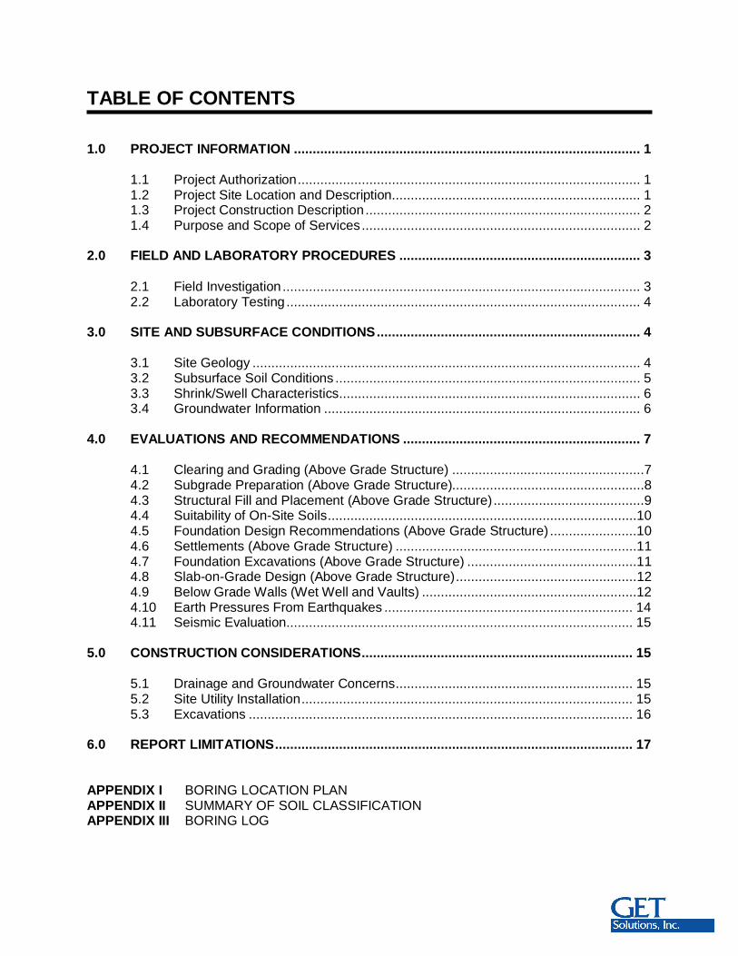
TABLE OF CONTENTS
1.0 PROJECT INFORMATION ............................................................................................ 1
1.1 Project Authorization........................................................................................... 11.2 Project Site Location and Description.................................................................. 11.3 Project Construction Description......................................................................... 21.4 Purpose and Scope of Services.......................................................................... 2
2.0 FIELD AND LABORATORY PROCEDURES ................................................................ 3
2.1 Field Investigation ............................................................................................... 32.2 Laboratory Testing .............................................................................................. 4
3.0 SITE AND SUBSURFACE CONDITIONS...................................................................... 4
3.1 Site Geology ....................................................................................................... 43.2 Subsurface Soil Conditions ................................................................................. 53.3 Shrink/Swell Characteristics................................................................................ 63.4 Groundwater Information .................................................................................... 6
4.0 EVALUATIONS AND RECOMMENDATIONS ............................................................... 7
4.1 Clearing and Grading (Above Grade Structure) ...................................................74.2 Subgrade Preparation (Above Grade Structure)...................................................84.3 Structural Fill and Placement (Above Grade Structure)........................................94.4 Suitability of On-Site Soils..................................................................................104.5 Foundation Design Recommendations (Above Grade Structure) .......................104.6 Settlements (Above Grade Structure) ................................................................114.7 Foundation Excavations (Above Grade Structure) .............................................114.8 Slab-on-Grade Design (Above Grade Structure)................................................124.9 Below Grade Walls (Wet Well and Vaults) .........................................................124.10 Earth Pressures From Earthquakes .................................................................. 144.11 Seismic Evaluation............................................................................................ 15
5.0 CONSTRUCTION CONSIDERATIONS........................................................................ 15
5.1 Drainage and Groundwater Concerns............................................................... 155.2 Site Utility Installation........................................................................................ 155.3 Excavations ...................................................................................................... 16
6.0 REPORT LIMITATIONS............................................................................................... 17
APPENDIX I BORING LOCATION PLANAPPENDIX II SUMMARY OF SOIL CLASSIFICATIONAPPENDIX III BORING LOG

Report of Subsurface Investigation and Geotechnical Engineering Services August 28, 2017Pump Station #22Hampton, VirginiaG E T Project No: WM17-150G
1
1.0 PROJECT INFORMATION
1.1 Project Authorization
G E T Solutions, Inc. has completed our subsurface investigation and geotechnicalengineering services for Pump Station #22 project located in Hampton, Virginia.Authorization to proceed with our services was received in the form of an executedsubcontractor agreement.
1.2 Project Site Location and Description
The project site is located at 279 West Gilbert Street in Hampton, Virginia. A site vicinitymap obtained from Google Earth is provided below.
Figure 1- Site Vicinity Map
Report of Subsurface Investigation and Geotechnical Engineering Services August 28, 2017Pump Station #22Hampton, VirginiaG E T Project No: WM17-150G
2
Currently, the project site contains an existing pump station situated towards thewestern end of the property. Currently, the project site is mainly a grass covered lot withtrees and various fencing around its perimeter. The pump station site has a grassovergrown gravel entrance from the alley located behind the residences at 255 and 257West Gilbert Street. The site is secured with a locked chain gate across its entrance.The project site is relatively flat and based on the provided drawing the site elevationsare generally around 6 feet MSL. Evidence of multiple underground utilities werepresent throughout the site along with a below grade vault-type structure at the pumpstation.
1.3 Project Construction Description
The construction at this site will consist of building a new pump station adjacent to theexisting pump station. The existing pump station is planned for demolition and removalonce the new proposed pump station is constructed and operational. The new pumpstation is planned to include a 120-ft2 above grade structure, a below grade wet well forthe sanitary gravity sewer, and two below grade vault structures for the sanitary force mainsewer. The wet well will consist of a 8-foot diameter precast concrete structure with aninvert elevation of around -3.1 feet MSL, which corresponds to roughly 9.5 to 10 feet belowexisting grades. The below grade vault structures will likely consist of concrete structures,possibly precast, with invert elevations around 0 and 4 feet MSL, which corresponds toroughly 2 and 6 feet below existing grades. The construction at this site is also expected toconsist of installing associated below grade utilities, surface concrete pavement, and otherassociated infrastructure components.
If any of the noted information is incorrect or has changed, please inform G E TSolutions, Inc. so that we may amend the recommendations presented in thisreport, if appropriate.
1.4 Purpose and Scope of Services
The purpose of this study was to obtain information on the general subsurfaceconditions at the proposed project sites. The subsurface conditions encountered werethen evaluated with respect to the available project characteristics. In this regard,engineering assessments for the following items were formulated:
1. General assessment of the soils revealed by the boring performed at the proposeddevelopment.
2. General location and description of potentially deleterious material encountered inthe boring that may interfere with construction progress or structure performance,including existing fills or surficial/subsurface organics.
3. Soil subgrade preparation, including stripping, grading and compaction. Engineeringcriteria for placement and compaction of approved structural fill material.
Report of Subsurface Investigation and Geotechnical Engineering Services August 28, 2017Pump Station #22Hampton, VirginiaG E T Project No: WM17-150G
3
4. Construction considerations for fill placement, subgrade preparation, and foundationexcavations.
5. Evaluation of the on-site soils for re-use as structural fill.
6. Feasibility of utilizing a shallow foundation system for support of the proposed pumpstation building. Design parameters required for the foundation system, includingfoundation sizes, allowable bearing pressures, foundation levels and expected totaland differential settlements.
7. Feasibility of utilizing a mat foundation for the base of the below grade structures(wet well and vaults). Soil design parameters required for establishing lateral stressdistribution diagrams and hydrostatic design recommendations for the wall system,as well as providing allowable bearing pressure and expected settlement.
8. Seismic site class determination in accordance with the 2012 International BuildingCode and our experience with similar soil conditions in the local area.
The scope of services did not include an environmental assessment for determining thepresence or absence of wetlands or hazardous or toxic material in the soil, bedrock,surface water, groundwater or air, on or below or around this site. Prior to developmentof this site, an environmental assessment is advisable.
2.0 FIELD AND LABORATORY PROCEDURES
2.1 Field Investigation
In order to explore the general subsurface soil types and to aid in developing associatedfoundation design parameters, one (1) 40-foot deep SPT boring (designated as B-1)was drilled within the vicinity of the proposed pump station’s footprint.
Standard Penetration Tests were performed in the field in general accordance withASTM D 1586. The tests were performed continuously from the existing ground surfaceto a depth of 12 feet, and at 5-foot intervals thereafter. The soil samples were obtainedwith a standard 1.4” I.D., 2” O.D., 30” long split-spoon sampler. The sampler was drivenwith blows of a 140 lb. hammer falling 30 inches, using an automatic hammer. Thenumber of blows required to drive the sampler each 6-inch increment of penetration wasrecorded and is shown on the boring logs. The sum of the second and third penetrationincrements is termed the SPT N-value (uncorrected for automatic hammer). Arepresentative portion of each disturbed split-spoon sample was collected with eachSPT, placed in a glass jar, sealed, labeled, and returned to our laboratory for review.
The boring location was established and staked in the field by a representative of G E TSolutions, Inc. The approximate boring location is shown on the attached “BoringLocation Plan” (Appendix I), which was reproduced based on the site plan provided bythe client.
Report of Subsurface Investigation and Geotechnical Engineering Services August 28, 2017Pump Station #22Hampton, VirginiaG E T Project No: WM17-150G
4
2.2 Laboratory Testing
Representative portions of all soil samples collected during drilling were sealed in glassjars, labeled and transferred to our laboratory for classification and analysis. AGeotechnical Engineer performed the soil classification in general accordance withASTM Specification D 2487. A summary of the soil classification system is provided inAppendix II.
Two (2) representative split spoon soil samples were selected and subjected to naturalmoisture and -#200 sieve wash testing and analysis in order to corroborate the visualclassification. These test results are tabulated below (Table I) and are also presentedon the “Boring Log” sheet (Appendix III).
Table I - Laboratory Test Results
BoringNo.
Depth(ft.)
NaturalMoisture (%)
Percent Passing#200
USCSClassification
B-1 7-8 34 28 SMB-1 18-20 35 19 SM
3.0 SITE AND SUBSURFACE CONDITIONS
3.1 Site Geology
The project site lies within a major physiographic province called the Atlantic CoastalPlain. Numerous transgressions and regressions of the Atlantic Ocean have depositedmarine, lagoonal, and fluvial (stream lain) sediments. The regional geology is verycomplex, and generally consists of interbedded layers of varying mixtures of sands, siltsand clays. Based on our review of existing geologic and soil boring data, the geologicstratigraphy encountered in our subsurface Investigations generally consisted of marinedeposited sands, silts and clays.

Report of Subsurface Investigation and Geotechnical Engineering Services August 28, 2017Pump Station #22Hampton, VirginiaG E T Project No: WM17-150G
5
3.2 Subsurface Soil Conditions
The results of our soil test boring are below in Table II.
Table II – Subsurface Soil Conditions
Notes: (1) SPT = Standard Penetration Test, N-Values in Blows-per-foot (uncorrected)
It is noted that the topsoil designation references the presence of surficial organic ladensoil, and does not represent any particular quality specification. This material should betested for approval prior to its use.
As boring B-1 is located adjacent to an existing pump station, we speculate that theFILL material encountered in this boring is related to the construction of the below gradecomponents for the pump station.
The subsurface description is of a generalized nature provided to highlight the major soilstrata encountered. The records of the subsurface Investigation are included inAppendix III (Boring Log sheet), which should be reviewed for specific information as tothe individual boring. The stratifications shown on the records of the subsurfaceInvestigation represent the conditions only at the actual boring location. Variations mayoccur and should be expected across the site. The stratifications represent theapproximate boundary between subsurface materials and the transition may be gradual.It is noted that the topsoil designation references the presence of surficial organic ladensoil, and does not represent any particular quality specification. It is recommended thatthis material be tested for approval prior to use.
AVERAGEDEPTH(Feet)
STRATUM DESCRIPTIONRANGES OF
SPT(1)
N-VALUES0to0.2
Topsoil 2 inches of Topsoil -
0.2to7.0
FILL FILL materials generally comprised of Clayey SAND (SC) with
trace Gravel and/or organics and Sandy Lean CLAY (CL) withtrace Gravel
4 - 10
7.0to8.0
I Silty SAND (SM) with trace Clay, contains marine shellfragments 5
8.0to
40.0II Silty SAND (SM), contains marine shell fragments, “Yorktown
Formation” 4 - 10
Report of Subsurface Investigation and Geotechnical Engineering Services August 28, 2017Pump Station #22Hampton, VirginiaG E T Project No: WM17-150G
6
3.3 Shrink/Swell Characteristics
The soils recovered during our field investigation were tested and evaluated for theirpotential to expand or contract with moisture changes (typically termed shrink-swell).Shallow foundations constructed on expansive soils at certain depths may be subjectedto detrimental uplift or horizontal forces caused by the swelling of these soils as a resultof an increase in the moisture content. Conversely, as these soils lose moisture theymay shrink, adversely affecting the foundations. The depth to which soils are normallyaffected by moisture changes extends to about 3 to 6 feet below existing grades in thisarea, depending on site topography and drainage characteristics.
The soils within the project site are mapped by the Soil Survey of Hampton as theNewflat-Urban Land Soil Series. The urban land designation indicates “man-placed”FILL material could be present. Our investigation revealed similar conditions with about7 feet of Uncontrolled FILL material encountered at the boring location. Based on ourfield and laboratory investigation, the natural soils at this project site encounteredbeneath the FILL material and extending to 10 feet below existing grades areconsidered to have a low expansive (shrink-swell) potential.
In order to minimize shrink-swell concerns and possibilities, the following preventativemeasures are typically practiced:
Increasing footing bearing depth.
Do not plant deep-rooted trees and shrubs within 10 feet of the foundations.
Moderately moisten the soils within 5 feet of the foundations during hot weatherconditions.
Tie roof drains to the storm water system and situate downspouts in such a mannerto prevent ponding water near the foundation.
3.4 Groundwater Information
The groundwater level was recorded at the boring location and as observed through thewetness of the recovered soil samples during the drilling operations. The initialgroundwater table was measured to occur at a depth of 7 feet below the existing sitegrades at the boring location. The borehole was backfilled upon completion for safetyconsiderations. As such, the reported groundwater level may not be indicative of thestatic groundwater level.
Report of Subsurface Investigation and Geotechnical Engineering Services August 28, 2017Pump Station #22Hampton, VirginiaG E T Project No: WM17-150G
7
Groundwater conditions will vary with environmental variations and seasonal conditions,such as the frequency and magnitude of rainfall patterns, as well as man-madeinfluences, such as existing swales, drainage ponds, underdrains and areas of coveredsoil (paved parking lots, sidewalks, etc.). Seasonal groundwater fluctuations of 2 feetare common in the project’s area; however, greater fluctuations have been documented.We recommend that the contractor determine the actual groundwater levels at the timeof the construction to determine groundwater impact on the construction procedures.
4.0 EVALUATIONS AND RECOMMENDATIONS
Our recommendations are based on the previously discussed project information, ourinterpretation of the soil test boring and laboratory data, and our observations during oursite reconnaissance. If the proposed construction should vary from what was described,we request the opportunity to review our recommendations and make any necessarychanges.
4.1 Clearing and Grading (Above-Grade Structure)
The proposed construction area should be cleared by means of removing vegetation,topsoil, root mat, fibrous materials, existing concrete, and any soft or otherwiseunsuitable subgrade soils. It is estimated that a cut of about 4 inches in depth will berequired to remove the majority of the topsoil and root mat materials. This cut isexpected to extend deeper in isolated areas to remove deeper deposits of topsoil, rootmat and any otherwise unsuitable soils. It is noted that Uncontrolled FILL materialwas observed at the boring location. Some of this Uncontrolled FILL material maypotentially remain in place under slabs and pavements if approved by theGeotechnical Engineer (to be determined following the completion of the test pits,proofroll, and compaction testing). Regardless, all Uncontrolled FILL materialmust be removed from below the base of all footing excavations. It isrecommended that the clearing operations extend laterally at least 5 feet beyond theperimeter of the proposed above grade structure area.
Following the initial clearing, the resulting exposed subgrade will generally becomprised of Uncontrolled FILL material consisting of Clayey SAND (SC) containing anappreciable amount of fines. Accordingly, combinations of excess surface moisture fromprecipitation ponding on the site and the construction traffic, including heavy compactionequipment, may create pumping and general deterioration of the bearing capabilities ofthe surface soils. Therefore, undercutting to remove loose/soft soils in isolated areasshould be expected. The extent of the undercut will be determined in the field duringconstruction based on the outcome of the field testing procedures (subgrade proofroll).In this regard, and in order to reduce undercutting, care should be exercised during thegrading and construction operations at the site.

Report of Subsurface Investigation and Geotechnical Engineering Services August 28, 2017Pump Station #22Hampton, VirginiaG E T Project No: WM17-150G
8
Inherently wet subgrade soils combined with potential poor site drainage make this siteparticularly susceptible to subgrade deterioration. Thus, grading operations at this sitewill be more economical if performed during the drier months of the year (historicallyApril through November). This should minimize these potential problems, although theymay not be eliminated. If grading is attempted during the winter months, undercutting ofwet soils should be anticipated. However, during the drier months of the year, wet soilscould be dried by disking or other drying procedures to achieve moisture contentsnecessary to achieve adequate degrees of compaction.
Similar projects have required significant improvements to stabilize or bridge unstablesubgrade soils, which tend to deteriorate when exposed to construction traffic andmoisture. The subgrade improvements typically consist of additional cuts of up to 1-footand replacement with structural fill to improve poor subgrade soil conditions. Theproject’s budget should include an allowance for subgrade improvements (undercut andbackfill with structural fill).
The site should be graded to enhance surface water runoff to reduce the ponding ofwater. Ponding of water often results in softening of the near-surface soils. In the eventof heavy rainfall within areas to receive fill, we recommend that the grading operationscease until the site has had a chance to dry.
4.2 Subgrade Preparation (Above-Grade Structure)
Following the clearing operation, the exposed subgrade soils within the slab-on-gradearea (above grade structure) should be densified with a large static drum or sheepsfootroller. Subgrades to a depth of at least 6 inches should be compacted to a dry density ofat least 98% of the Standard Proctor maximum dry density, in accordance with ASTM D698 (if possible). The moisture content of the subgrade should be within +/- 2% of theoptimum moisture content at the time of compaction. These compaction and moisturerecommendations may not be achievable in the relatively wet environment. As such,some subgrade improvements should be expected.
After the subgrade soils have been compacted, they should be evaluated by G E TSolutions, Inc. for stability. Accordingly, the subgrade soils should be proofrolled tocheck for pockets of loose material hidden beneath a crust of better soil. Several passesshould be made by a large rubber-tired roller or loaded dump truck over the constructionareas. The number of passes will be determined in the field by the GeotechnicalEngineer depending on the soil conditions. Any pumping and unstable areas observedduring proofrolling (beyond the initial cut) should be undercut and/or stabilized at thedirection of the Geotechnical Engineer. These improvement recommendations (whererequired) should also consider the thickness of the subbase and its ability to bridgemarginal areas.
Report of Subsurface Investigation and Geotechnical Engineering Services August 28, 2017Pump Station #22Hampton, VirginiaG E T Project No: WM17-150G
9
In addition to the proofroll, several 6 to 8-foot deep test pits should be excavated withinthe proposed construction areas. The test pits are considered necessary to determinethe thickness and composition of the Uncontrolled FILL material. The test pits should beperformed under the observation of a representative G E T Solutions, Inc., who willevaluate the composition of the recovered soils. In addition to the test pits and proofroll,several compaction tests should be performed on the Uncontrolled FILL material withinthe proposed slab and pavement areas and to further substantiate the suitability of theexisting material. It is likely that some subgrade improvements will be required toprovide suitable soils for slab and pavement support. The Uncontrolled FILL materialmay potentially remain in place under slabs and pavements if approved by theGeotechnical Engineer (to be determined following the completion of the test pits,proofroll, and compaction testing). Regardless, all Uncontrolled FILL material must beremoved from below the base of all footing excavations.
Recommendations concerning the subgrade improvements (as necessary) will beprovided in the field following the testing procedures. The project’s budget shouldinclude an allowance for subgrade improvements (undercut and backfill with structuralfill).
4.3 Structural Fill and Placement (Above-Grade Structure)
Following the approval of the natural sub-grade soils by the Geotechnical Engineer andimplementation of any recommended subgrade modification, the placement of the fillrequired to establish the design grades may begin (if required). Any material to be usedfor select fill should be evaluated prior to placement to determine if they are suitable forthe intended use.
Any material to be used for structural fill should be evaluated and tested by G E TSolutions, Inc. prior to placement to determine if they are suitable for the intended use.Suitable structural fill material should consist of sand or gravel containing less than 25%by weight of fines (SP, SM, SW, GP, GW - with dimensions not to exceed 2 inches indiameter), having a liquid limit less than 20 and plastic limit less than 6, and should befree of rubble, organics, clay, debris and other unsuitable material.
All structural fill should be compacted to a dry density of at least 98% of the StandardProctor maximum dry density, in accordance with ASTM D 698. The moisture contentof the structural fill should be within +/- 2% of the optimum moisture content at the timeof placement. In general, the compaction should be accomplished by placing the fill inmaximum 8-inch loose lifts and mechanically compacting each lift to at least thespecified minimum dry density.
Backfill material in utility trenches within the construction areas should consist ofstructural fill (as previously described), and should be compacted to at least 98% ofASTM D 698. This fill should be placed in 4 to 6 inch loose lifts when hand compactionequipment is used.
Report of Subsurface Investigation and Geotechnical Engineering Services August 28, 2017Pump Station #22Hampton, VirginiaG E T Project No: WM17-150G
10
We recommend that fill placement be monitored on a full-time basis by a qualifiedGeotechnical Engineering firm to verify that the specified materials are used and therequired degree of compaction is achieved. The monitoring should follow the guidelinesin the VDOT Specifications.
Surface water control measures should be instituted to protect the new fill from erosion.A protective cover of grass or other vegetation should be established on permanentslopes as soon as possible during construction.
4.4 Suitability of On-Site Soils
The Uncontrolled FILL material and Stratum I soils do not appear to meet the criteriarecommended in this report for reuse as structural fill, but may be used as fill withingreen areas. Stratum II soils, which was comprised of Silty SAND (SM), appears tomeet the criteria recommended in this report for reuse as structural fill. However, thesesoils were encountered below the groundwater table and would therefore requiresignificant moisture manipulation prior to their reuse. As such, it will be necessary toimport structural fill to expedite the utility backfilling. Further classification testing(natural moisture content, gradation analysis, and Proctor testing) should be performedin the field during construction to evaluate the suitability of excavated soils for reuse asfill within the utility alignments.
4.5 Foundation Design Recommendations (Above-Grade Structure)
Provided that the previous construction procedures are properly performed, theproposed above-grade structure can be supported by shallow foundations over firmnatural soil or well compacted select fill. These may consist of slabs with turn downedges, or a simple mat foundation. Uncontrolled FILL material is not consideredsuitable for foundation support and must be removed from below all footings.The Uncontrolled FILL material extended to about 7 feet below existing grades atour boring location, but could vary at other locations across the project site.
The turn down edges can be designed using a net allowable soil pressure of 2,000pounds per square foot (psf) or a mat foundation can be designed using a net allowablesoil pressure of 500 psf. In using net pressures, the weight of the turn down edges,including the weight of the floor slab, need not be considered. Hence, only loadsapplied at or above the finished floor need to be used for dimensioning the turn downedges.
In order to develop the recommended bearing capacity, the base of the turn downedges should have an embedment of at least 18 inches beneath finished grades andthe turn down edges should have a minimum width of 18 inches. The recommended18-inch turn down edge foundation embedment is considered sufficient to provideadequate cover against frost penetration to the bearing soils.
Report of Subsurface Investigation and Geotechnical Engineering Services August 28, 2017Pump Station #22Hampton, VirginiaG E T Project No: WM17-150G
11
4.6 Settlements (Above Grade Structure)
It is estimated that, with proper site preparation, the maximum resulting total settlementof the proposed above-grade structure foundations should be up to 1 inch. Themaximum differential settlement magnitude is expected to be less than 1/2-inch acrossthe foundations in areas subjected to varying loading conditions. The settlements wereestimated on the basis of the results of the field penetration tests. Careful field controlwill contribute substantially towards minimizing the settlements.
4.7 Foundation Excavations (Above Grade Structure)
In preparation for shallow foundation support, the foundation excavations should extendinto firm natural soil or well compacted select fill. Again, Uncontrolled FILL material isnot considered suitable for foundation support and must be removed from below allfootings. Uncontrolled FILL material was encountered to as deep as 7 feet belowexisting grades at the boring location. This Uncontrolled FILL depth may extend deeperat other locations across the project site. All foundation excavations should be observedby G E T Solutions, Inc. At that time, the Geotechnical Engineer should also explorethe extent of excessively loose, soft, or otherwise unsuitable material within the exposedexcavations. Also, at the time of turn down foundation observations, the GeotechnicalEngineer may find it necessary to perform hand auger borings or use a handpenetration device in the bases of the foundation excavations. The necessary depth ofpenetration will be established during the subgrade observations.
If unsuitable soils (such as the Uncontrolled FILL) requiring undercut are encountered inthe foundation excavations, the proposed footing elevation should be re-established bybackfilling after the unsuitable material has been removed. This backfilling may be donewith very lean concrete, VDOT No. 57 stone, or with a well-compacted, suitable selectfill such as sand (as described in Section 4.3 of this report). It is noted that thegroundwater table was encountered at the same depth as the upper limits ofStratum I, about 7 feet below existing grades. Since the foundation excavationswill likely need to extend to a similar depth to penetrate through the UncontrolledFILL material it is anticipated that some means of dewatering will be required forfoundation construction. We recommend that the contractor determine the actualgroundwater levels at the time of the construction to determine groundwater impact onthe construction procedures.
Immediately prior to reinforcing steel placement, it is suggested that the bearingsurfaces of all turn down edge foundation and floor slab areas be compacted usinghand operated mechanical tampers, to a dry density of at least 98% of the StandardProctor maximum dry density (ASTM D698) as tested to a depth of 12 inches, forbearing capacity considerations. In this manner, any localized areas, which have beenloosened by excavation operations, should be adequately recompacted.
Report of Subsurface Investigation and Geotechnical Engineering Services August 28, 2017Pump Station #22Hampton, VirginiaG E T Project No: WM17-150G
12
Soils exposed in the bases of all satisfactory foundation excavations should beprotected against any detrimental change in condition such as from physicaldisturbance, rain or frost. Surface run-off water should be drained away from theexcavations and not be allowed to pond. If possible, all foundation concrete should beplaced the same day the excavation is made. If this is not possible, the footingexcavations should be adequately protected.
4.8 Slab-on-grade Design (Above Grade Structure)
As an alternative to slabs with turn down edges, the floor slab may be constructed asslab-on-grade members provided the previously recommended earthwork activities andevaluations are carried out properly. It is recommended that all ground floor slabs bedirectly supported by at least a 4-inch layer of relatively clean, compacted, poorlygraded sand (SP) or gravel (GP) with less than 5% passing the No. 200 Sieve (0.074mm). The purpose of the 4-inch layer is to act as a capillary barrier and equalizemoisture conditions beneath the slab.
It is recommended that all slab-on-grade floors be "floating". That is, generally groundsupported and not rigidly connected to walls or foundations. This is to minimize thepossibility of cracking and displacement of the floor slabs because of differentialmovements between the slab and the foundation.
It is also recommended that the floor slab bearing soils be covered by a vapor barrier orretarder in order to minimize the potential for floor dampness, which can affect theperformance of glued tile and carpet. Generally, use a vapor retarder for minimal vaporresistance protection below the slab on grade. When floor finishes, site conditions orother considerations require greater vapor resistance protection, consideration shouldbe given to using a vapor barrier. Selection of a vapor retarder or barrier should bemade by the Architect based on project requirements.
4.9 Below Grade Walls (Wet Well and Vaults)
It is expected that the below grade walls will consist of earth-retaining structures (wetwell and vaults) supported over a mat foundation bearing at a depths ranging from 2 to10 feet below existing grades. Uncontrolled FILL material is not considered suitablefor foundation support and must be removed from below all mat foundations.Although the mat foundation for the wet well is expected to extend below thedepth of the Uncontrolled FILL material it is likely the below grade vaults mayrequire over-excavation to expose natural soils. Undercut excavations required toremove the Uncontrolled FILL material from the base of the vault excavations can be re-established with VDOT No. 57 stone.

Report of Subsurface Investigation and Geotechnical Engineering Services August 28, 2017Pump Station #22Hampton, VirginiaG E T Project No: WM17-150G
13
These mats can be designed using a net allowable soil pressure of 1,000 psf. It is notedthat in order to promote excavation base stability and facilitate the cast-in-placeplacement, a bedding layer of 12 to 18 inches of VDOT No. 57 stone is recommendedto be placed in the base of the excavation. Furthermore, the resultant of the soilpressure distribution across the width of the mat foundation should pass through themiddle third of the foundation cross section.
In order to reduce the magnitude of lateral loads being applied to the below grade wallsand to promote positive water drainage, it is recommended that a granular backfill beplaced directly behind the walls. These granular soils should be a relatively clean, freedraining granular material (SAND) classified as SP-SM or better, containing less than12% passing the No. 200 sieve (0.074 mm). Filter fabric should be installed between thedrainage material and the existing site soils to prevent fines from contaminating thedrainage material. The compaction behind these walls should be in the range of 95% to97% of the Standard Proctor maximum dry density (ASTM D 698). The soils in this zoneshould not be over-compacted. In order to minimize the potential for wall damage due toexcessive compaction, hand operated mechanical tampers should be used to compactthe granular materials. Heavy compaction equipment should not be allowed within fivefeet of the below grade walls.
The walls should be sized with consideration given to hydrostatic pressures. Thesepressures should assume the water table to occur near the ground surface. In all cases,the below grade walls should be designed for the 100 year FEMA flood loads.
A representative of G E T Solutions, Inc. should visit the site during the below gradewall construction to verify that the soils in the base of the excavation are consistent withthose encountered during our subsurface investigation.
With regard to the design of the below grade walls to resist lateral earth pressures, theestimated soil parameters presented in Table III can be used.
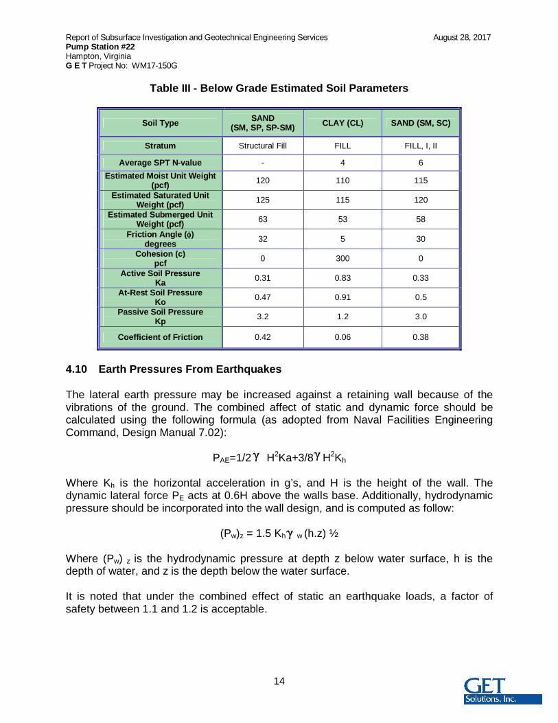
Report of Subsurface Investigation and Geotechnical Engineering Services August 28, 2017Pump Station #22Hampton, VirginiaG E T Project No: WM17-150G
14
Table III - Below Grade Estimated Soil Parameters
Soil Type SAND(SM, SP, SP-SM) CLAY (CL) SAND (SM, SC)
Stratum Structural Fill FILL FILL, I, II
Average SPT N-value - 4 6Estimated Moist Unit Weight
(pcf) 120 110 115
Estimated Saturated UnitWeight (pcf) 125 115 120
Estimated Submerged UnitWeight (pcf) 63 53 58
Friction Angle ( )degrees 32 5 30
Cohesion (c)pcf 0 300 0
Active Soil PressureKa 0.31 0.83 0.33
At-Rest Soil PressureKo 0.47 0.91 0.5
Passive Soil PressureKp 3.2 1.2 3.0
Coefficient of Friction 0.42 0.06 0.38
4.10 Earth Pressures From Earthquakes
The lateral earth pressure may be increased against a retaining wall because of thevibrations of the ground. The combined affect of static and dynamic force should becalculated using the following formula (as adopted from Naval Facilities EngineeringCommand, Design Manual 7.02):
PAE=1/2 H2Ka+3/8 H2Kh
Where Kh is the horizontal acceleration in g’s, and H is the height of the wall. Thedynamic lateral force PE acts at 0.6H above the walls base. Additionally, hydrodynamicpressure should be incorporated into the wall design, and is computed as follow:
(Pw)z = 1.5 Kh w (h.z) ½
Where (Pw) z is the hydrodynamic pressure at depth z below water surface, h is thedepth of water, and z is the depth below the water surface.
It is noted that under the combined effect of static an earthquake loads, a factor ofsafety between 1.1 and 1.2 is acceptable.
Report of Subsurface Investigation and Geotechnical Engineering Services August 28, 2017Pump Station #22Hampton, VirginiaG E T Project No: WM17-150G
15
4.11 Seismic Evaluation
Based on our experience within the vicinity of the project site and the recovered soils atthis location, it is our opinion that this site may be classified as a Site Class “D” inaccordance with Chapter 20 of ASCE 7 as referenced by the 2012 International BuildingCode. However, the seismic evaluation requires soils information associated with theupper 100 feet. If the site classification is critical to the structural design it will benecessary to perform a 100-foot deep CPT boring with shear wave velocity testing tosubstantiate the site classification.
5.0 CONSTRUCTION CONSIDERATIONS
5.1 Drainage and Groundwater Concerns
It is expected that dewatering will be required for excavations that extend near or belowthe existing groundwater table. Dewatering above the groundwater level could probablybe accomplished by pumping from sumps. Dewatering at depths below the groundwaterlevel will require well pointing.
It would be advantageous to construct all fills early in the construction. If this is notaccomplished, disturbance of the existing site drainage could result in collection ofsurface water in some areas, thus rendering these areas wet and very loose.Temporary drainage ditches should be employed by the contractor to accentuatedrainage during construction. Again, we recommend that the contractor determine theactual groundwater levels at the time of construction to determine groundwater impacton this project.
5.2 Site Utility Installation
The base of the utility trenches should be observed by a qualified inspector prior to thepipe and structure placement to verify the suitability of the bearing soils. Based on theresults of our field investigation program it is expected that the utilities and structures atthis site will bear in the granular or cohesive soils. In some instances the bearing soilsmay require some stabilization to provide suitable bedding. This stabilization is typicallyaccomplished by providing additional VDOT No. 57 stone bedding (typically 12 inches).
It is expected that excavations within the granular soils will experience varying degreesof cave-in as a result of the soils composition (Sand). Shoring should be implemented toreduce the potential cave-ins.
The resulting excavations should be backfilled with structural fill, as described in Section4.3 of this report. A majority of the subsurface soils will not be suitable for reuse asbackfill. As such, it is likely that imported structural fill material will be required toexpedite the utility installation.
Report of Subsurface Investigation and Geotechnical Engineering Services August 28, 2017Pump Station #22Hampton, VirginiaG E T Project No: WM17-150G
16
5.3 Excavations
In Federal Register, Volume 54, No. 209 (October, 1989), the United States Departmentof Labor, Occupational Safety and Health Administration (OSHA) amended its“Construction Standards for Excavations, 29 CFR, part 1926, Subpart P”. Thisdocument was issued to better insure the safety of workmen entering trenches orexcavations. It is mandated by this federal regulation that all excavations, whether theybe utility trenches, basement excavation or footing excavations, be constructed inaccordance with the new (OSHA) guidelines. It is our understanding that theseregulations are being strictly enforced and if they are not closely followed, the ownerand the contractor could be liable for substantial penalties.
The contractor is solely responsible for designing and constructing stable, temporaryexcavations and should shore, slope, or bench the sides of the excavations as requiredto maintain stability of both the excavation sides and bottom. The contractor’sresponsible person, as defined in 29 CFR Part 1926, should evaluate the soil exposedin the excavations as part of the contractor’s safety procedures. In no case shouldslope height, slope inclination, or excavation depth, including utility trench excavationdepth, exceed those specified in local, state, and federal safety regulations.
We are providing this information solely as a service to our client. G E T Solutions,Inc. is not assuming responsibility for construction site safety or the contractor’sactivities; such responsibility is not being implied and should not be inferred.
Report of Subsurface Investigation and Geotechnical Engineering Services August 28, 2017Pump Station #22Hampton, VirginiaG E T Project No: WM17-150G
17
6.0 REPORT LIMITATIONS
The recommendations submitted are based on the available soil information obtainedby G E T Solutions, Inc. and the information supplied by the client and theirconsultants for the proposed project. If there are any revisions to the plans for thisproject or if deviations from the subsurface conditions noted in this report areencountered during construction, G E T Solutions, Inc. should be notified immediatelyto determine if changes in the foundation recommendations are required. IfG E T Solutions, Inc. is not retained to perform these functions, G E T Solutions, Inc.can not be responsible for the impact of those conditions on the geotechnicalrecommendations for the project.
The Geotechnical Engineer warrants that the findings, recommendations, specificationsor professional advice contained herein have been made in accordance with generallyaccepted professional geotechnical engineering practices in the local area. No otherwarranties are implied or expressed.
After the plans and specifications are more complete the Geotechnical Engineer shouldbe provided the opportunity to review the final design plans and specifications to assureour engineering recommendations have been properly incorporated into the designdocuments, in order that the earthwork and foundation recommendations may beproperly interpreted and implemented. At that time, it may be necessary to submitsupplementary recommendations. This report has been prepared for the exclusive useof Woolpert and their consultants for the specific application to the Pump Station #22project located in Hampton, Virginia.
APPENDICES
APPENDIX I BORING LOCATION PLAN
APPENDIX II SUMMARY OF SOIL CLASSIFICATION
APPENDIX III BORING LOG

APPENDIX I
BORING LOCATION PLAN
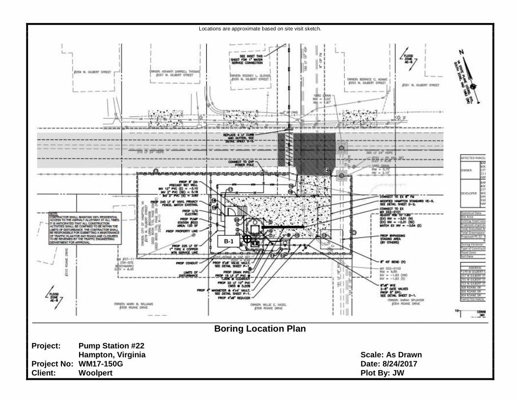
Locations are approximate based on site visit sketch.
_____________________________________________________________________________________________________________________________________________________________
Boring Location Plan
Project: Pump Station #22Hampton, Virginia Scale: As Drawn
Project No: WM17-150G Date: 8/24/2017Client: Woolpert Plot By: JW
B-1
APPENDIX II
SUMMARY OF SOIL CLASSIFICATION
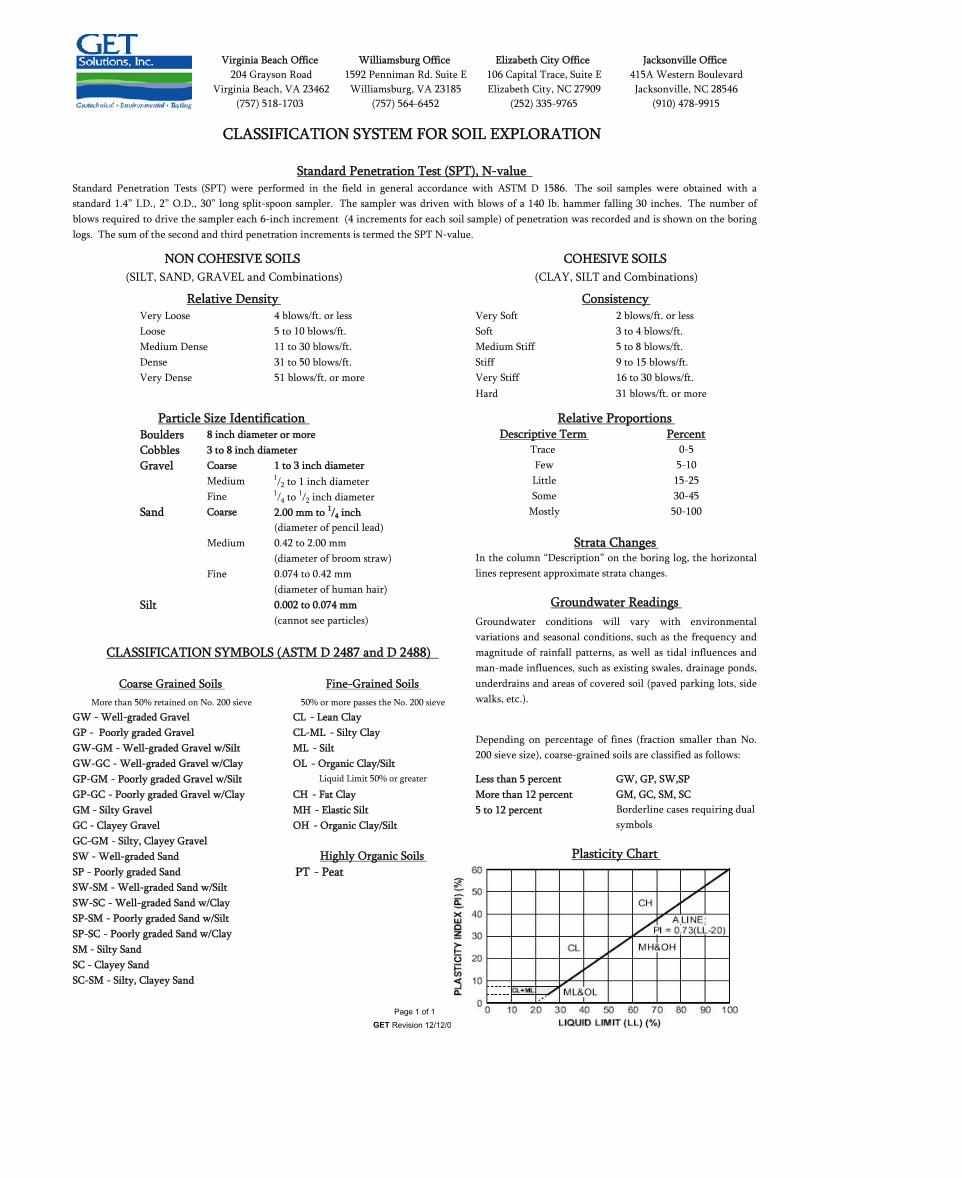
Very Loose 4 blows/ft. or less Very Soft 2 blows/ft. or lessLoose 5 to 10 blows/ft. Soft 3 to 4 blows/ft.Medium Dense 11 to 30 blows/ft. Medium Stiff 5 to 8 blows/ft.Dense 31 to 50 blows/ft. Stiff 9 to 15 blows/ft.Very Dense 51 blows/ft. or more Very Stiff 16 to 30 blows/ft.
Hard 31 blows/ft. or more
Boulders 8 inch diameter or moreCobbles 3 to 8 inch diameterGravel Coarse 1 to 3 inch diameter
Medium 1/2 to 1 inch diameterFine 1/4 to
1/2 inch diameterSand Coarse 2.00 mm to 1/4 inch
(diameter of pencil lead)Medium 0.42 to 2.00 mm
(diameter of broom straw)Fine 0.074 to 0.42 mm
(diameter of human hair)Silt 0.002 to 0.074 mm
(cannot see particles)
GW - Well-graded Gravel CL - Lean ClayGP - Poorly graded Gravel CL-ML - Silty ClayGW-GM - Well-graded Gravel w/Silt ML - SiltGW-GC - Well-graded Gravel w/Clay OL - Organic Clay/SiltGP-GM - Poorly graded Gravel w/Silt Less than 5 percent GW, GP, SW,SPGP-GC - Poorly graded Gravel w/Clay CH - Fat Clay More than 12 percent GM, GC, SM, SCGM - Silty Gravel MH - Elastic Silt 5 to 12 percentGC - Clayey Gravel OH - Organic Clay/SiltGC-GM - Silty, Clayey GravelSW - Well-graded SandSP - Poorly graded Sand PT - PeatSW-SM - Well-graded Sand w/SiltSW-SC - Well-graded Sand w/ClaySP-SM - Poorly graded Sand w/SiltSP-SC - Poorly graded Sand w/ClaySM - Silty SandSC - Clayey SandSC-SM - Silty, Clayey Sand
CLASSIFICATION SYMBOLS (ASTM D 2487 and D 2488)
More than 50% retained on No. 200 sieve
Groundwater conditions will vary with environmentalvariations and seasonal conditions, such as the frequency andmagnitude of rainfall patterns, as well as tidal influences andman-made influences, such as existing swales, drainage ponds,underdrains and areas of covered soil (paved parking lots, sidewalks, etc.).
LittleSome
Mostly 50-100
Borderline cases requiring dualsymbols
Plasticity Chart
Strata ChangesIn the column “Description” on the boring log, the horizontallines represent approximate strata changes.
Groundwater Readings
Depending on percentage of fines (fraction smaller than No.200 sieve size), coarse-grained soils are classified as follows:
15-2530-45
Few
COHESIVE SOILS(CLAY, SILT and Combinations)
Relative ProportionsDescriptive Term Percent
0-55-10
Jacksonville Office415A Western BoulevardJacksonville, NC 28546
(910) 478-9915
Virginia Beach Office204 Grayson Road
Virginia Beach, VA 23462(757) 518-1703
Relative Density
NON COHESIVE SOILS(SILT, SAND, GRAVEL and Combinations)
Standard Penetration Tests (SPT) were performed in the field in general accordance with ASTM D 1586. The soil samples were obtained with astandard 1.4” I.D., 2” O.D., 30” long split-spoon sampler. The sampler was driven with blows of a 140 lb. hammer falling 30 inches. The number ofblows required to drive the sampler each 6-inch increment (4 increments for each soil sample) of penetration was recorded and is shown on the boringlogs. The sum of the second and third penetration increments is termed the SPT N-value.
CLASSIFICATION SYSTEM FOR SOIL EXPLORATION
Standard Penetration Test (SPT), N-value
1592 Penniman Rd. Suite EWilliamsburg, VA 23185
Particle Size Identification
Consistency
Page 1 of 1GET Revision 12/12/07
Coarse Grained Soils Fine-Grained Soils
Highly Organic Soils
50% or more passes the No. 200 sieve
Liquid Limit 50% or greater
Trace
Williamsburg Office
(757) 564-6452
Elizabeth City Office106 Capital Trace, Suite EElizabeth City, NC 27909
(252) 335-9765

APPENDIX III
BORING LOG
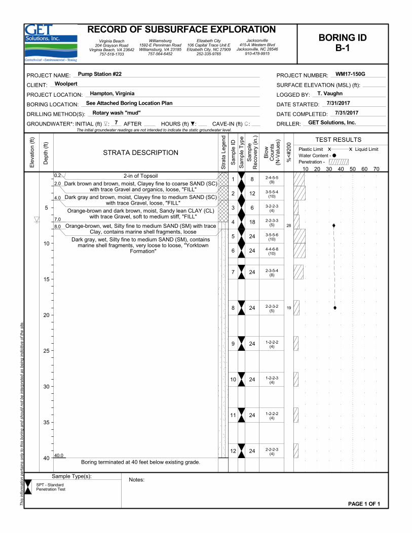
2-4-5-5(9)
3-5-5-4(10)
3-2-2-3(4)
2-2-3-3(5)
3-5-5-6(10)
4-4-6-8(10)
2-3-5-4(8)
2-2-3-2(5)
1-2-2-2(4)
1-2-2-3(4)
1-2-2-2(4)
2-2-2-3(4)
2-in of Topsoil
Dark brown and brown, moist, Clayey fine to coarse SAND (SC)with trace Gravel and organics, loose, "FILL"
Dark gray and brown, moist, Clayey fine to medium SAND (SC)with trace Gravel, loose, "FILL"
Orange-brown and dark brown, moist, Sandy lean CLAY (CL)with trace Gravel, soft to medium stiff, "FILL"
Orange-brown, wet, Silty fine to medium SAND (SM) with traceClay, contains marine shell fragments, loose
Dark gray, wet, Silty fine to medium SAND (SM), containsmarine shell fragments, very loose to loose, "Yorktown
Formation"
Boring terminated at 40 feet below existing grade.
28
19
8
12
6
18
24
24
24
24
24
24
24
24
1
2
3
4
5
6
7
8
9
10
11
12
0.2
2.0
4.0
7.0
8.0
40.0
INITIAL (ft) : 7 CAVE-IN (ft) :
Notes:
x
Blo
wC
ount
s(N
-Val
ues)
RECORD OF SUBSURFACE EXPLORATIONBORING ID
B-1
10 20 30 40 50 60 70
5
10
15
20
25
30
35
40
AFTER HOURS (ft) :
STRATA DESCRIPTION
%<
#200
Sam
ple
Rec
over
y (in
.)
GROUNDWATER*:
PROJECT LOCATION: Hampton, Virginia
CLIENT: Woolpert
PROJECT NAME: Pump Station #22
DATE COMPLETED: 7/31/2017
SURFACE ELEVATION (MSL) (ft):
Dep
th (
ft)
Water Content -
Sample Type(s):
Liquid Limit
Virginia Beach204 Grayson Road
Virginia Beach, VA 23642757-518-1703
Ele
vatio
n (f
t)
PAGE 1 OF 1
Sam
ple
Typ
e
Sam
ple
ID
Str
ata
Lege
nd
The initial groundwater readings are not intended to indicate the static groundwater level.
Thi
s in
form
atio
n pe
rta
ins
only
to th
is b
orin
g an
d sh
oul
d no
t be
inte
rpre
ted
as b
eing
indi
citiv
e of
the
site
.
DRILLER: GET Solutions, Inc.
DATE STARTED: 7/31/2017
LOGGED BY: T. Vaughn
PROJECT NUMBER: WM17-150G
Williamsburg1592-E Penniman RoadWilliamsburg, VA 23185
757-564-6452
BORING LOCATION: See Attached Boring Location Plan
Elizabeth City106 Capital Trace Unit EElizabeth City, NC 27909
252-335-9765
Jacksonville415-A Western Blvd
Jacksonville, NC 28546910-478-9915
TEST RESULTS
Penetration -
SPT - StandardPenetration Test
DRILLING METHOD(S): Rotary wash "mud"
Plastic Limit x


![Construction Contract [Master]](https://img.pdfslide.us/doc/110x75/5695d4b31a28ab9b02a26bb7/construction-contract-master.jpg)