Embed Size (px)
Citation preview

WEIR CONTROL & CHOKE VALVES ExcellentPower & IndustrialSolutions
ExcellentEngineeringSolutions
Contour Trim Valves & Three Way Valves

www.weirpowerindustrial.comWeir Control & Choke valves Engineered valves for protection & process control2
Weir Control & Choke Valves Process Control Valves
ContentsTop & Bottom guided valves 3Top & Bottom guided valves description 4Top & Bottom guided valves trim design 5Top & Bottom guided valves selection 6Top & Bottom guided valves design Cv 7Top & Bottom guided valves dimensions 8Three Way valves 9Three Way valves description 10Three Way valves trim design 11Three Way valves selection 12Three Way valves Cv’s & dimensions 13Bonnet forms 14Flow characterstics 15
Quality assuranceWeir is qualified to industry standards and working practices including:
� ASME BPVC Section III (N and NPT Stamp) � NQA-1 Quality system � 10CFR50 App. B � 10CFR50 Part 21 � RCC-E � RCC-M � CSA Z299 � Performance testing and qualification to:ASME QME-1ASME B16.41IEEE 323IEEE 344IEEE 382
� ISO 9001:2008 � ISO 14001 � PED 97/23/CE � API Q1 TO API LICENCES:
API 6D (6D-0182)API 6A (64-0445)
� OHSAS 18001 � ATEX 94/9/CE � Lean manufacturing practices
A proven track recordWe have extensive references and a proven track record in the supply of valves across a number of key industries.
Our valves are industry renowned brands, each with an established reputation for quality engineering and reliability.
Valve testingAll pressure containing items are hydrostatically tested, seat leakage tested and functionally tested.
We can also perform gas, packing emission, cryogenic and advanced functional testing, as well as seismic testing for nuclear applications.
Material testing � Non-destructive examination by radiography, ultrasonics, magnetic particle and liquid penetrant.
� Chemical analysis by computer controlled direct reading emission spectrometer.
� Mechanical testing for tensile properties at ambient and elevated temperatures, bend and hardness testing. Charpy testing at ambient, elevated and sub-zero temperatures.
Aftermarket solutionsOur valve aftermarket solutions are based on our engineering heritage, applying our OEM knowledge and expertise to maintenance strategies, life extension and upgrade projects.
Weir Control & Choke Valves provides a wide range of control valves for the process industry. These include severe service, choke, desuperheating and turbine bypass applications. Our world-wide reputation is based on engineering excellence applied to a comprehensive range of specialist products and effective customer support.
Weir UK purpose built factory at Elland
Member of
Weir International, South Korea

Weir Control & Choke valves Engineered valves for protection & process control 3www.weirpowerindustrial.com
Weir Control & Choke Valves Top & Bottom Guided Valves
Design features � Single & double seated
� Wide range of trim options
� Balanced & unbalanced designs
� Field reversible
� High capacity
Pressure rating � Class 150 to 1500
� PN10 to PN250
Sizes � 40mm to 600mm (11⁄2” to 24”)
BV800/1/2/3 Top & Bottom Guided Valves

www.weirpowerindustrial.comWeir Control & Choke valves Engineered valves for protection & process control4
Weir Control & Choke Valves Top & Bottom Guided Valves
Description
The Weir range of top and bottom guided valves are suited to a wide range of general process applications, such as water, steam, oil, gases and the majority of chemical services. The basic design incorporates a standard contour or ’V’ Port plug form as the control element, however, the valves construction allows more specialised trims to be fitted.
The BV800 and BV801 double seated valve offers high capacity on low to medium pressure drop applications.
The design is inherently balanced allowing the use of diaphragm actuators for the majority of applications. For higher pressure drop conditions, the valve can be supplied with multi-flow sleeves to give low pressure recovery. The design is not suited for tight shut-off applications.
The BV 802 and BV 803 series are single seated valves. They offer high rangeability, tight shut-off capability and can also be fitted with anti-cavitation/low noise trims.
Design features � Top and bottom guided
� Wide range of trim options
� High capacity (BV800/1)
� Excellent rangeability
� Action is field reversible
� High integrity closure (BV802/3)
� Inherently characterised trim
� BV801/BV803 are ‘pull stem’ to close
Pressure rating � ASME Class 150 to 1500
� PN10 to PN250
Sizes � 40mm to 600mm (BV800/1) 11⁄2” to 24” (BV800/1)
� 40mm to 250mm (BV802/3) 11⁄2” to 10” (BV802/3)
Travels � 28.5mm to 152mm 11⁄8” to 6”
End connections � Flanged
� Butt weld
� Socket weld
� Screwed
BV802/3 top and bottom guided valve, single seated type, arranged for pull stem to open. The valve illustrated is shown with linear contoured trim. There are a variety of other trim design options.
BV800/1 top and bottom guided valve, double seated type, arranged for pull stem to open. The valve illustrated is shown with linear contoured trim. There are a variety of other trim design options.

Weir Control & Choke valves Engineered valves for protection & process control 5www.weirpowerindustrial.com
Weir Control & Choke Valves Top & Bottom Guided Valves
Trim options
Contour/”V” Port
Several trim options are available as standard in the top and bottom guided series of valves. The contour “V” port trim presents a smooth profile to the flow leading to relatively high pressure recovery which is ideal for low pressure drop flow control applications. These designs are suitable for the majority of control applications.
Characteristics Seat Options � Equal percent
� Metal to metal
� Linear
� Resilient seal
� Quick open
� Hard faced
BV802/3 valve with soft face trim.BV802/3 valve with multi-flow trim.
BV800/1 valve with multi-flow trim.
Standard contour trims. Plugs can be inverted to change the ’fail’ action of the valve.
Multi-flow Trim
The multi-flow trim is designed for applications where customers require the top and bottom guided style of valve associated with the benefits of the traditional cage guided valve.
� Low noise
� Anti cavitation
� Low pressure recovery
The trim option can also be inverted if it is desired to change the actuator action.
BV802/BV803 Valves with soft face trim
The soft face trim option is specified on applications where bubble tight closure is required. It is only available on the single seated valves where the un-balanced nature of the valve allows a better class of seat closure.
The soft seal is fitted into the plug head and retained by a shroud. The seat is designed with a lip so that when the plug head contacts the seat, the seat face is deformed to produce a high integrity seal.
BV800/1 valve with contour trim. BV802/3 valve with contour trim.

www.weirpowerindustrial.comWeir Control & Choke valves Engineered valves for protection & process control6
Weir Control & Choke Valves Top & Bottom Guided Valves
Valve selection guidelines
Valve flow coefficient
All valves are sized using the valve flow coefficient, Cv, in accordance with ISA 75.01.01 as detailed in the Weir sizing and selection manual. Design Cv values are given in table 6.
Body Selection
The valve body size and style is selected on the basis of supporting the selected trim design and Cv. In addition consideration is made of
the velocity and the required pressure drop application. Liquid velocities are limited mainly due to erosion considerations, whereas gas or vapour flow velocities are limited for trim stability noise and vibration considerations.
Trim Selection
The selection criteria of the valve trim ranges through valve flow coefficient, rangeability, pressure drop, cavitation, flashing and noise consideration. Weir sizing and selection manual details the various calculation methods and selection limitations for each trim design.
TABLE 1 – Standard material combinations
TABLE 2 – Trim material combinations
PTFE gaskets are suitable for temperatures up to 232oC (450oF); above this the gasket material is specifically considered. Materials listed are standard combination only. Other material combinations can be accommodated. Trim materials specified can be supplied to conform to NACE Specification.
Material can be supplied to UOP spec. Other material combinations are available.
TABLE 3 – Recommended limiting inlet velocities for control valves
Note: 0.3 sonic for low noise applications
Body Bonnet Carbon Steel Chrome Moly 304 or 304L 347 ST.ST. 316 ST.ST. Hastelloy Monel Alloy 20 Duplex Bottom Cast or Wrought ST.ST. ST.ST. B or C Flange Body Gasket 316 ST.ST. 316 ST.ST. 316 ST.ST. 316 ST.ST. 316 ST.ST. PTFE PTFE PTFE PTFE
Body Studs/Nuts B7/2H B7/2H or B16/7 B8/8 B8/8 B8/8 B8/8 B8/8 B8/8 B8/8
Plug
Seat
Stem
Guide Bush
Packing Parts
316 ST.ST.
316 ST.ST.
316 ST.ST.
440C ST.ST.
316 ST.ST.
316 Stellite Faced
316 Stellite Faced
316 ST.ST.
440C ST.ST.
316 ST.ST.
316 Full Stellite
316 Full Stellite
316 ST.ST.
Stellite
316 ST.ST.
Hastelloy B/C
Hastelloy B/C
Hastelloy B/C
Stellite
Hastelloy B/C
Monel 400
Monel 400
Monel 400
Monel K500
Monel 400
Alloy 20
Alloy 20
Alloy 20
Stellite
Alloy 20
17-4PH ST.ST.
17-4PH ST.ST.
316 ST.ST.
440C ST.ST.
316 ST.ST.
NACE 316 ST.ST.
316 ST.ST.
316 ST.ST.
Stellite
316 ST.ST.
Duplex
Duplex
Duplex
Stellite
Duplex
VALVE SIZE
40 & 50mm (11⁄2” & 2”)
80 & 100mm (3” & 4”)
150 & 200mm (6” & 8”)
250 to 600mm (10” to 24”)
LIQUID M/S
12
11
10.5
7.5
LIQUID FT/S
40
36
30
25
STEAM OR GAS M/S
105
100
90
70
STEAM OR GAS FT/S
350
315
275
225
MAX OUTLET
(STEAM or GAS)
0.65 x SONIC
TABLE 4 – Control valve leak rates in accordance with ASME/FCI 70-2 (IEC 60534-4)
VALVE STYLE
BV800 & BV801 Double Seated Valves
BV802 & BV803 Single Seated Valves
BV802 & BV803 Single Seated Valves
BV802 & BV803 Single Seated Valve
TRIM STYLE
Metal Faced
Unbalanced Metal to Metal
Unbalanced Metal to Metal Lapped Seats
Unbalanced Resilient Seat
LEAKAGE CLASS
Class III
Class IV
Class V
Class VI
MAXIMUM ALLOWABLE LEAKAGE
0.1% of Rated Capacity
0.01% Rated Capacity
0.0005ml/min of water per Inch of PortDiameter per PSI differential
Bubble Tight

Weir Control & Choke valves Engineered valves for protection & process control 7www.weirpowerindustrial.com
Weir Control & Choke Valves Top & Bottom Guided Valves
TABLE 5 – Rangeability for control valves
Note: Standard/inherant rangeability of linear characteristic trims is 20:1 corresponding to a valve opening of 5%. Control at openings less than 5% is not recommended for prolonged periods.
TABLE 6 – Design Cv values
CF = Consult factory
BV800 & BV801 DOUBLE SEATED BV802 & BV803 SINGLE SEATED
EQUAL %
40mm (11⁄2”)50mm (2”)80mm (3”)
100mm (4”)150mm (6”)200mm (8”)
250mm (10”)300mm (12”)400mm (16”)500mm (20”)600mm (24”)
3260
140255520780
13501700256051007400
2032
100140375520780
1350210025605100
132060
100255375520780
170021002560
2852
115170340550900
1350CFCFCF
202876
115240340550900CFCFCF
13205276
170240340555CFCFCF
TRIM TYPE BODY SIZE FULRATE MIDRATE LORATE FULRATE MIDRATE LORATE
LINEAR
40mm (11⁄2”)50mm (2”)80mm (3”)
100mm (4”)150mm (6”)200mm (8”)
250mm (10”)300mm (12”)400mm (16”)500mm (20”)600mm (24”)
3765
140255575
100014401850280055007950
2537
100140415575
10001440220028005500
172565
100255415575
1000185022002800
3052
110190390650950
1430CFCFCF
203085
110285390650950CFCFCF
13205285
190285390650CFCFCF
QUICK OPEN
40mm (11⁄2”)50mm (2”)80mm (3”)
100mm (4”)150mm (6”)200mm (8”)
250mm (10”)300mm (12”)400mm (16”)500mm (20”)600mm (24”)
3765
140255575
100014401850280050008200
2537
100140415575
10001440220028005800
172565
100255415575
10001850220
2800
3058
125230450800
12501650
CFCFCF
253080
125340450800
1250CFCFCF
15255880
230340450800CFCFCF
BV800 & BV801 DOUBLE SEATED BV802 & BV803 SINGLE SEATED
VALVE SIZE
40 & 50mm (11⁄2” & 2”)
80 & 100mm (3” & 4”)
150 & 200mm (6” & 8”)
250 to 600mm (10” to 24”)
FULRATE
30:1
40:1
45:1
50:1
MIDRATE
30:1
30:1
40:1
45:1
LORATE
20:1
30:1
30:1
30:1
FULRATE
40:1
60:1
70:1
80:1
MIDRATE
40:1
50:1
60:1
70:1
LORATE
30:1
40:1
50:1
60:1
www.weirpowerindustrial.comWeir Control & Choke valves Engineered valves for protection & process control8
Weir Control & Choke Valves Top & Bottom Guided Valves
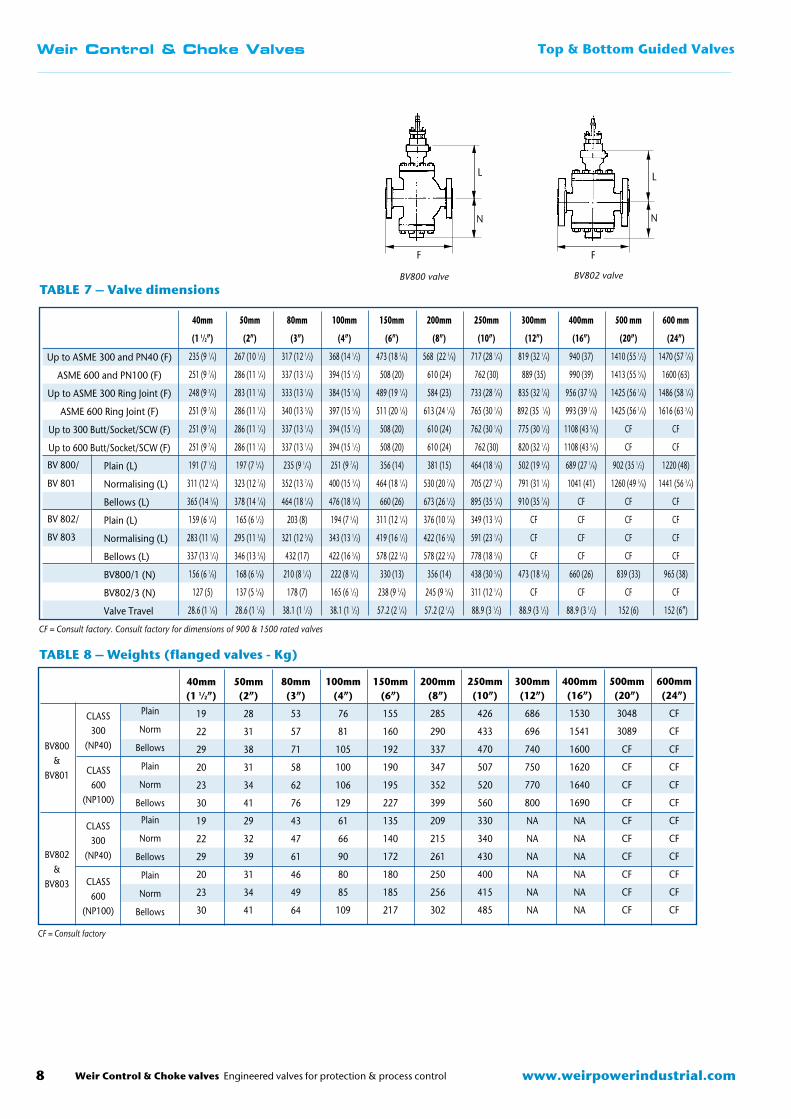
CF = Consult factory. Consult factory for dimensions of 900 & 1500 rated valves
TABLE 7 – Valve dimensions
Up to ASME 300 and PN40 (F)
ASME 600 and PN100 (F)
Up to ASME 300 Ring Joint (F)
ASME 600 Ring Joint (F)
Up to 300 Butt/Socket/SCW (F)
Up to 600 Butt/Socket/SCW (F)
Plain (L)
Normalising (L)
Bellows (L)
Plain (L)
Normalising (L)
Bellows (L)
BV800/1 (N)
BV802/3 (N)
Valve Travel
BV 800/
BV 801
BV 802/
BV 803
40mm
(1 1⁄2”)
235 (9 1⁄4)
251 (9 7⁄8)
248 (9 3⁄4)
251 (9 7⁄8)
251 (9 7⁄8)
251 (9 7⁄8)
191 (7 1⁄2)
311 (12 1⁄4)
365 (14 3⁄8)
159 (6 1⁄4)
283 (11 1⁄8)
337 (13 1⁄4)
156 (6 1⁄8)
127 (5)
28.6 (1 1⁄8)
50mm
(2”)
267 (10 1⁄2)
286 (11 1⁄4)
283 (11 1⁄8)
286 (11 1⁄4)
286 (11 1⁄4)
286 (11 1⁄4)
197 (7 3⁄4)
323 (12 7⁄8)
378 (14 7⁄8)
165 (6 1⁄2)
295 (11 5⁄8)
346 (13 5⁄8)
168 (6 3⁄8)
137 (5 3⁄8)
28.6 (1 1⁄8)
80mm
(3”)
317 (12 1⁄2)
337 (13 1⁄4)
333 (13 1⁄8)
340 (13 3⁄8)
337 (13 1⁄4)
337 (13 1⁄4)
235 (9 1⁄4)
352 (13 7⁄8)
464 (18 1⁄4)
203 (8)
321 (12 5⁄8)
432 (17)
210 (8 1⁄4)
178 (7)
38.1 (1 1⁄2)
100mm
(4”)
368 (14 1⁄2)
394 (15 1⁄2)
384 (15 1⁄8)
397 (15 5⁄8)
394 (15 1⁄2)
394 (15 1⁄2)
251 (9 7⁄8)
400 (15 3⁄4)
476 (18 3⁄4)
194 (7 5⁄8)
343 (13 1⁄2)
422 (16 5⁄8)
222 (8 3⁄4)
165 (6 1⁄2)
38.1 (1 1⁄2)
150mm
(6”)
473 (18 5⁄8)
508 (20)
489 (19 1⁄4)
511 (20 1⁄8)
508 (20)
508 (20)
356 (14)
464 (18 1⁄4)
660 (26)
311 (12 1⁄4)
419 (16 1⁄2)
578 (22 3⁄4)
330 (13)
238 (9 3⁄8)
57.2 (2 1⁄4)
200mm
(8”)
568 (22 3⁄8)
610 (24)
584 (23)
613 (24 1⁄8)
610 (24)
610 (24)
381 (15)
530 (20 7⁄8)
673 (26 1⁄2)
376 (10 7⁄8)
422 (16 5⁄8)
578 (22 3⁄4)
356 (14)
245 (9 5⁄8)
57.2 (2 1⁄4)
250mm
(10”)
717 (28 1⁄4)
762 (30)
733 (28 7⁄8)
765 (30 1⁄8)
762 (30 1⁄8)
762 (30)
464 (18 1⁄8)
705 (27 3⁄4)
895 (35 1⁄4)
349 (13 3⁄4)
591 (23 1⁄4)
778 (18 5⁄8)
438 (30 5⁄8)
311 (12 1⁄4)
88.9 (3 1⁄2)
300mm
(12”)
819 (32 1⁄4)
889 (35)
835 (32 7⁄8)
892 (35 1⁄8)
775 (30 1⁄2)
820 (32 1⁄4)
502 (19 3⁄4)
791 (31 1⁄8)
910 (35 7⁄8)
CF
CF
CF
473 (18 5⁄8)
CF
88.9 (3 1⁄2)
400mm
(16”)
940 (37)
990 (39)
956 (37 5⁄8)
993 (39 1⁄8)
1108 (43 5⁄8)
1108 (43 5⁄8)
689 (27 1⁄8)
1041 (41)
CF
CF
CF
CF
660 (26)
CF
88.9 (3 1⁄2)
500 mm
(20”)
1410 (55 1⁄2)
1413 (55 5⁄8)
1425 (56 1⁄8)
1425 (56 1⁄8)
CF
CF
902 (35 1⁄2)
1260 (49 5⁄8)
CF
CF
CF
CF
839 (33)
CF
152 (6)
600 mm
(24”)
1470 (57 7⁄8)
1600 (63)
1486 (58 1⁄4)
1616 (63 5⁄8)
CF
CF
1220 (48)
1441 (56 3⁄4)
CF
CF
CF
CF
965 (38)
CF
152 (6”)
BV800 valve
L
N
F
BV802 valve
L
N
F
TABLE 8 – Weights (flanged valves - Kg)
BV800&
BV801
BV802&
BV803
CLASS300
(NP40)
CLASS600
(NP100)
Plain
Norm
Bellows
Plain
Norm
Bellows
Plain
Norm
Bellows
Plain
Norm
Bellows
CLASS300
(NP40)
CLASS600
(NP100)
CF = Consult factory
40mm(1 1⁄2”)
19
22
29
20
23
30
19
22
29
20
23
30
50mm(2”)
28
31
38
31
34
41
29
32
39
31
34
41
80mm(3”)
53
57
71
58
62
76
43
47
61
46
49
64
100mm(4”)
76
81
105
100
106
129
61
66
90
80
85
109
150mm(6”)
155
160
192
190
195
227
135
140
172
180
185
217
200mm(8”)
285
290
337
347
352
399
209
215
261
250
256
302
250mm(10”)
426
433
470
507
520
560
330
340
430
400
415
485
300mm(12”)
686
696
740
750
770
800
NA
NA
NA
NA
NA
NA
400mm(16”)
1530
1541
1600
1620
1640
1690
NA
NA
NA
NA
NA
NA
500mm(20”)
3048
3089
CF
CF
CF
CF
CF
CF
CF
CF
CF
CF
600mm(24”)
CF
CF
CF
CF
CF
CF
CF
CF
CF
CF
CF
CF

Weir Control & Choke valves Engineered valves for protection & process control 9www.weirpowerindustrial.com
Weir Control & Choke Valves 3 Way Valves
BV830 & BV831 3 Way Control Valves
Design features � Top & skirt guided
� High capacity
� High stability
� Easy maintenance
� Wide range of trim options
Pressure rating � ASME Class 150 to 1500
� PN10 to PN250
Sizes � 40mm to 400mm (11⁄2” to 16”)

www.weirpowerindustrial.comWeir Control & Choke valves Engineered valves for protection & process control10
Weir Control & Choke Valves 3 Way Valves
Description
The BV830/831 valves are designed for either blending two different flows or for dividing a flow into two proportional amounts. The valves can be used on a wide range of process applications for air, water, steam, oil, gases and chemical services.
The BV830 has two inlets and a common outlet branch: it is used for proportional blending of two flows into one stream, on such applications as control of process fluid temperature downstream of heat exchangers, or as mixing valves to control the composition of service media. It can also be used for flow splitting duties. The total capacity is constant irrespective of plug position.
The BV831 valve is used for proportional control on flow splitting applications. This valve has two outlets and a common inlet branch. They are used for proportional flow splitting, diverting a portion of the process medium from one part of a system to another.
A typical application is on the upstream side of heat exchangers to control the temperature of the process fluid.
Design features � Top and skirt guided
� Wide range of trim sizes
� High capacity
� High stability
� Balanced
Pressure rating � ASME Class 150 to 1500
� PN10 to PN250
Sizes � 40mm to 400mm 11⁄2” to 16”
Travels � 28.5mm to 89mm 11⁄8” to 31⁄2”
End connections � Flanged
� Butt weld (on special request)
� Socket weld (on special request)
� Screwed (on special request)
BV830 three way valve for flow mixing applications. The valve can also be used for flow splitting if the flow is in reverse
BV831 three way valve for flow splitting applications

Weir Control & Choke valves Engineered valves for protection & process control 11www.weirpowerindustrial.com
Weir Control & Choke Valves 3 Way Valves
Trim options
”V” Port Standard Trim
The standard trim design for three way applications is the “V” port plug. This design provides high flow capacity, high rangeability and good leakage capability. Other trim options are available as semi-special in the three way valve.
BV831 valve with cascade trimBV831 valve with soft face trim
BV830 valve with soft face trimBV830 valve standard contour trim BV831 valve standard contour trim
BV830 Normal FlowMixing (Blending)
BV830 Reverse FlowSplitting (Diverting)
BV831 Normal FlowSplitting (Diverting)
BV830/BV831 Valves with soft face trim
The soft face trim option is specified on applications where bubble tight closure is required.
The soft seal is fitted into the plug head and retained by a shroud. The seat is designed with a lip so that when the plug head contacts the seat a high integrity valve closure is achieved.
Severe Service Trim
Specialist severe service trims can be accommodated within the BV830 body design.
The cascade trim is normally used for applications where the flow requires treatment at source to prevent cavitation and high noise levels on high pressure drop liquid and gas applications.
� Low noise
� Anti-cavitation
� Low pressure recovery
FLOW DIRECTION
Characteristics � Linear
� Equal percentage (special applications)
� Linear cascade (multi-stage)
Seat Options � Metal to metal
� Soft face
� Hard faced

www.weirpowerindustrial.comWeir Control & Choke valves Engineered valves for protection & process control12
Weir Control & Choke Valves 3 Way Valves
Valve selection guidelines
Valve flow coefficient
All valves are sized using the valve flow coefficient, Cv, in accordance with ISA 75.01.01 as detailed in the Weir sizing and selection manual. Design Cv values are given in table 4.
Body Selection
The valve body size and style is selected on the basis of supporting the selected trim design and design Cv. In addition, consideration is made of the velocity and the required pressure drop application. Liquid velocities are limited mainly due to erosion considerations, whereas gas or vapour flow velocities are limited for trim stability noise and vibration considerations.
TABLE 1 – Standard material combinations
PTFE gaskets are suitable for temperatures up to 232oC (450oF); above this the gasket material is specifically considered. Materials listed are standard combination only. Other material combinations can be accommodated. Trim materials specified can be supplied to conform to NACE Specification.
Material can be supplied to UOP spec. Other material combinations are available.
TABLE 2 – Trim material combinations
TABLE 3 – Recommended limiting inlet velocities for control valves
Note: 0.3 sonic for low noise applications
Trim Selection
The selection criteria of the valve trim ranges through valve flow coefficient, rangeability, pressure drop, cavitation, flashing and noise consideration. Weir sizing and selection manual details the various calculation methods and selection limitations for each trim design.
Body Bonnet Bottom Flange
Body Gasket
Body Studs/Nuts
Carbon Steel
316 ST.ST
B7/2H
Chrome Moly Steel
316 ST.ST
B7/2H or B16/7
304 or 304L ST.ST.
316 ST.ST
B8/8
347 ST.ST.
316 ST.ST
B8/8
316 ST.ST.
316 ST.ST
B8/8
Hastelloy B or C
PTFE
B8/8
Monel
PTFE
B8/8
Alloy 20
PTFE
B8/8
Duplex
PTFE
B8/8
VALVE SIZE
40 & 50mm (1 1⁄2” & 2”)
80 & 100mm (3” & 4”)
150 & 200mm (6” & 8”)
250 to 400mm
(10” to 16”)
LIQUID M/S
12
11
10.5
7.5
LIQUID FT/S
40
36
30
25
STEAM OR GAS M/S
105
100
90
70
STEAM OR GAS FT/S
350
315
275
225
MAX OUTLET
(STEAM or GAS)
0.65 x SONIC
Plug
Seat
Stem
Guide Bush
Packing Parts
316 ST.ST.
316 ST.ST.
316 ST.ST.
440C ST.ST.
316 ST.ST.
316 Stellite Faced
316 Stellite Faced
316 ST.ST.
440C ST.ST.
316 ST.ST.
316 Full Stellite
316 Full Stellite
316 ST.ST.
Stellite
316 ST.ST.
Hastelloy B/C
Hastelloy B/C
Hastelloy B/C
Stellite
Hastelloy B/C
Monel 400
Monel 400
Monel 400
Monel K500
Monel 400
Alloy 20
Alloy 20
Alloy 20
Stellite
Alloy 20
17-4PH ST.ST.
17-4PH ST.ST.
316 ST.ST.
440C ST.ST.
316 ST.ST.
NACE 316 ST.ST.
316 ST.ST.
316 ST.ST.
Stellite
316 ST.ST.
Duplex
Duplex
Duplex
Duplex
Duplex
BV830 valve
L
G
FBV831 valve
L
H
F

Weir Control & Choke valves Engineered valves for protection & process control 13www.weirpowerindustrial.com
Weir Control & Choke Valves 3 Way Valves
TABLE 4 – Flow coefficients Cv (US units)
TRIM TYPE BODY SIZE FULRATE FULRATEBV830 BV831
LINEAR
40mm (1 1⁄2”)
50mm (2”)
80mm (3”)
100mm (4”)
150mm (6”)
200mm (8”)
250mm (10”)
300mm (12”)
400mm (16”)
27
40
90
145
300
550
775
1200
2200
27
40
90
130
340
500
725
1100
2100
TABLE 5 – Normal control valves leak rates
TRIM STYLE
ASME LEAKAGE
CLASS MAXIMUM ALLOWABLE LEAKAGE
Unbalanced Metal to Metal
Unbalanced Metal to Metal Lapped Seats
Unbalanced Soft Face
Class IV
Class V
Class VI
0.01% Rated Capacity
0.0005 ml of water per inch of port diameter per PSI differential
Bubble Tight
TABLE 6 – Valve dimensions
F
G
H
F
G
H
F
G
H
F
G
H
L
L
L
L
L
40mm(1 1⁄2”)
235 (9 1⁄4)
157 (6 3⁄16)
187 (7 3⁄8)
251(9 7⁄8)
164 (6 7⁄16)
195 (7 11⁄16)
248 (9 3⁄4)
160 (6 5⁄16)
190 (7 1⁄2)
251 (9 7⁄8)
167 (6 9⁄16)
196
(7 3⁄4)
159 (6 1⁄4)
283 (11 1⁄8)
191 (7 1⁄2)
311 (12 1⁄4)
365 (14 3⁄8)
28.6 (1 1⁄8)
50mm(2”)
267 (10 1⁄2)
168 (6 5⁄8)
200 (7 7⁄8)
286 (11 1⁄4)
178 (7)
210 (8 1⁄4)
283 (11 1⁄8)
172 (6 3⁄4)
204 (8)
289
181 (7 1⁄8)
211
(8 5⁄16)
165 (6 1⁄2)
295 (11 5⁄8)
197 (7 3⁄4)
323 (12 7⁄8)
378 (14 7⁄8)
28.6 (1 1⁄8)
80mm(3”)
317 (12 1⁄2)
200 (7 7⁄8)
232 (9 1⁄8)
337 (13 1⁄4)
229 (9)
260 (10 1⁄4)
333 (13 1⁄8)
204 (8)
236 (9 1⁄4)
340
332 (9 1⁄8)
261
(10 5⁄16)
203 (8)
321 (12 5⁄8)
235 (9 1⁄4)
352 (13 7⁄8)
464 (18 1⁄4)
38.1 (1 1⁄2)
100mm(4”)
368 (14 1⁄2)
216 (8 1⁄2)
273 (10 3⁄4)
394 (15 1⁄2)
267 (10 1⁄2)
324 (12 3⁄4)
384 (15 1⁄8)
220 (8 5⁄8)
277 (10 7⁄8)
397
270 (9 1⁄4)
325
(12 3⁄16)
194 (7 5⁄8)
343 (13 1⁄2)
251 (9 7⁄8)
400 (15 3⁄4)
476 (18 3⁄4)
38.1 (1 1⁄2)
150mm(6”)
473 (18 5⁄8)
273 (10 3⁄4)
319 (12 9⁄16)
508 (20)
319 (12 9⁄16)
367 (14 7⁄16)
489 (19 11⁄4)
277 (11)
323 (12 11⁄16)
511
322 (12 11⁄16)
368
(14 1⁄2)
311 (12 1⁄4)
419 (16 1⁄2)
356 (14)
464 (18 1⁄4)
660 (26)
57.2 (2 1⁄4)
200mm(8”)
568 (22 3⁄8)
306 (12 1⁄16)
379 (14 15⁄16)
610 (24)
368 (14 1⁄2)
435 (17 1⁄8)
584 (23)
310 (12 1⁄8)
383 (15 1⁄16)
613
371 (14 5⁄8)
436
(17 3⁄16)
376 (10 7⁄8)
422 (16 5⁄8)
381 (15)
530 (20 7⁄8)
673 (26 1⁄2)
57.2 (2 1⁄4)
250mm(10”)
718 (28 1⁄4)
413 (16 1⁄4)
540 (21 1⁄4)
762 (30)
440 (17 5⁄16)
562 (22 1⁄8)
733 (28 7⁄8)
417 (16 3⁄8)
565 (22 1⁄4)
765
443 (17 7⁄16)
563
(22 3⁄16)
349 (13 3⁄4)
591 (23 1⁄4)
464 (18 1⁄8)
705 (27 3⁄4)
895 (35 1⁄4)
88.9 (3 1⁄2)
300mm(12”)
775 (38 1⁄2)
433 (17)
562 (22 1⁄8)
820 (32 1⁄4)
455 (17 15⁄16)
584 (23)
791 (31 1⁄8)
437 (17 1⁄4)
565 (22 1⁄4)
823
458 (18)
585
(23 1⁄16)
CF
CF
502 (19 3⁄4)
791 (31 1⁄8)
910 (35 7⁄8)
88.9 (3 1⁄2)
400mm(16”)
940 (37)
508 (20)
635 (25)
990 (39)
533 (21)
660 (26)
956 (37 5⁄8)
515 (20 1⁄4)
638 (25 1⁄8)
993 (39 1⁄8)
536 (21 1⁄8)
661
(26 1⁄16)
CF
CF
689 (27 1⁄8)
1041 (41)
CF
88.9 (3 1⁄2)
Up to ASME 300 and PN40
ASME 600 and PN100
Up to ASME 300 Ring Joint
ASME 600 Ring Joint
Plain (L)
Normalising (L)
Plain (L)
Normalising (L)
Bellows (L)
Valve Travel
CF = Consult factory
TABLE 7 – Weights (flanged valves - Kg)
BV830 CLASS300
(NP40)
CLASS600
(NP100)
BV831CLASS
300(NP40)
CLASS600
(NP100)
Plain
Norm
Plain
Norm
Plain
Norm
Bellows
Plain
Norm
Bellows
CF = Consult factory
40mm(1 1⁄2”)
20
22
22
24
23
26
35
24
28
36
50mm(2”)
35
38
38
44
34
38
46
37
41
49
80mm(3”)
50
54
55
59
64
68
85
70
75
91
100mm(4”)
68
73
95
115
91
98
126
120
127
155
150mm(6”)
150
155
210
255
186
192
230
228
234
272
200mm(8”)
253
259
320
365
342
348
405
416
422
479
250mm(10”)
401
411
510
580
515
520
516
480
498
582
300mm(12”)
CF
CF
CF
CF
823
835
888
836
850
960
400mm(16”)
CF
CF
CF
CF
CF
CF
CF
CF
CF
CF

www.weirpowerindustrial.comWeir Control & Choke valves Engineered valves for protection & process control14
Weir Control & Choke Valves Process Control Valves
NormalisingStandard
PTFE Chevron
Grafoil
Bonnet forms
Standard
For applications where the temperature of the controlled fluid is between -18˚C (0˚F) and 232˚C (450˚F). May be used with graphite packing up to 315˚C (600 ˚F). Although modern packagings are suitable for much higher temperatures, it is recommended that the normalising bonnet be fitted in cases where the temperatures exceed the above values to accommodate lagging of the control valve body.
Normalising
For protection of the gland packing at temperatures above 232˚C (450˚F) and below -18˚C (0˚F) down to -100 ˚C (-150˚F) The bonnet is designed with fins which dissipate the heat from process fluid and help protect the packings and actuator assembly from high temperatures. In addition, the normalising bonnet is longer than the standard bonnet so that the valve can easily be lagged without interference with the actuator.
Bellows Seal
A positive leakproof stem seal for cases where gland leakage cannot be permitted. The standard bellows material is 321 stainless steel, although many other materials are available on request. The design consists of a welded flexible steel bellows which is clamped in an extended bonnet/bonnet hood. This effectively cuts out any possible leakage path around the plug stem and therefore prevents emissions from the valve packings. Packings are fitted in these valves but only act as a backup to the bellows.
Cryogenic
Used for temperatures below -100˚C (-150˚F). The bonnet designed with a long necked section which distances the packing away from the process fluid. The necked section is designed with a minimum wall section to minimise heat transfer. Cold box extension/cryogenic bonnets are also available.
Packing
Packings are selected based on fluid temperature and fluid type. The most common packing system materials are PTFE for low temperature and graphite for high temperature. For hydrocarbon service and where emission levels need to be controlled, further types of packings are available. Packings have been tested to prove emission levels of less than 500 parts per million over 50,000 cycles and under thermal cycling conditions.
Bellows Seal Cryogenic
Silencers
Silencers/Dynamic Attenuator
This equipment is used on gas/vapour services to control fluid velocity and to produce dynamic attenuation. Each silencer is designed for its specific application and is considered in conjunction with the selection of the upstream control valve/trim. In selecting the silencer design, all operating conditions are considered to ensure acceptable performance.
PTFE Chevron
Used for applications where the temperature is between cryogenic and 232˚C (450˚F)
Grafoil
Used on high temperature applications where the temperature exceeds 232˚C (450˚F)
Other packing types can be accommodated as required.

Weir Control & Choke valves Engineered valves for protection & process control 15www.weirpowerindustrial.com
Weir Control & Choke Valves Process Control Valves
Characteristics
Linear
This characteristic provides a flow rate which is directly proportional to the valve lift. The proportional relationship produces a characteristic with a constant slope, so that with constant pressure drop the valve gain will be the same at all flows. The linear valve plug is commonly specified for liquid level control and for flow control applications requiring constant gain.
Equal Percentage
Equal increments of valve lift produce equal percentage changes in the fluid flow. The change in flow rate is always proportional to the flow rate just before the change in plug position is made. The equal percentage characteristic is generally used on pressure control applications, and on other applications where a large percentage of pressure drop is normally absorbed by the system itself. Valves with this characteristic should also be considered where highly varying pressure drop conditions occur or high rangeability is required.
Quick Opening
This provides for maximum change in flow rate at low valve lifts with a fairly linear relationship. Additional increases in valve lift give sharply reduced changes in flow rate. When the valve plug nears the wide open position, the change in flow rate approaches zero.
Intermediate
Other intermediate or special characteristics are available on request to meet specific control requirements.
0 10 20 30 40 50 60 70 80 90 100
100
90
80
70
60
50
40
30
20
10
0
% F
low
rate
Valve lift % of full llift
Qui
ck o
peni
ng
Linea
r
Modified =%
=%

Weir Valves & Controls UK Ltd
Britannia House Huddersfield Road Elland, West Yorkshire HX5 9JR England
Tel: +44 (0) 1422 282 000 Fax: +44 (0) 1422 282 100 Email: [email protected] www.weirvalve.com
Britannia House Huddersfield Road Elland, West Yorkshire HX5 9JR England
Tel: +44 (0) 1422 282 000 Fax: +44 (0) 1422 282 100 Email: [email protected] www.weirvalve.com
Hopkinsons
Britannia House Huddersfield Road Elland, West Yorkshire HX5 9JR England
Tel: +44 (0) 1422 282 000Fax: +44 (0) 1422 282 100Email: [email protected]
Blakeborough Controls
Batley Valve
Britannia House Huddersfield Road Elland, West Yorkshire HX5 9JR England
Tel: +44 (0) 1422 282 000 Fax: +44 (0) 1422 282 100 Email: [email protected] www.weirvalve.com
Britannia House Huddersfield Road Elland, West Yorkshire HX5 9JR England
Tel: +44 (0) 1422 282 000 Fax: +44 (0) 1422 282 100 Email: [email protected] www.weirvalve.com
Excellent Engineering Solutions
Excellent Engineering Solutions
Excellent Engineering Solutions
Excellent Engineering Solutions
ExcellentEngineeringSolutions
Weir Control & Choke Valves
CT 6-0412
Copyright © 2012 Weir Valves & Controls UK Ltd.
Cover
East Kilbride, UK
Elland, UK
Fort St. John, Canada
Toronto, CanadaMontréal, Canada
Calgary, Canada
Boston, USA
Singapore, Malaysia
Alloa, UK
AsiaWeir International Korea10 Block 16 , Banwol Ind Complex, #779-10 Wonshi Dong, Ansan-Shi, Gyonggi-Do, South KoreaT +82 31 494 2345 F +82 31 495 3737 [email protected]
Weir Valves & Controls BeijingRM2207H, Derun Tower, 3A East Yong An Li, Jianwai Avenue, Chaoyang District, Beijing 100022T +86 (10) 8528 8315 / 8316 / 8317 F +86 (10) 8528 8318 [email protected] Loftyman Flow ControlUnit C16F, Hengtong InternationalBuilding no. 855Chang Ning RoadShanghai200050ChinaT +86 (21) 6240 1860F +86 (21) 6240 [email protected]
Weir Power & Industrial Pte Ltd - Singapore15 Tukang Innovation Drive, Singapore 618299T +65 63020880 F +65 [email protected] Weir-BDK ValvesA unit of Weir India Private Ltd47/48 Gokul Road, Hubli-580 030, IndiaT +91 836 4248222/2333930 F +91 836 4248484/2330799 [email protected]
EuropeWeir Valves & Controls UK LtdBritannia House, Huddersfield Road, Elland, West Yorkshire, HX3 9JRT +44 (0) 1422 282000 F +44 (0) 1422 282100 [email protected]
Middle East & AfricaWeir Valves & Controls Middle EastOffice No. Q3 40-41, Sharjah Airport International Free Zone, Sharjah, UAET +971 6 598 1300 Board / +971 6 5578160 F +971 6 557 8460 [email protected]
Weir Valves & Controls South Africa31 Isando Road, Johannesburg, Gauteng 1600T +27 (0) 11 929 2906 F +27 (0) 11 929 2925 [email protected]
AmericasBoston29 Old Right Road Ipswich, MA 01938, USAT +1 978-744-5690 F +1 978-741-3626 [email protected]
Toronto2360 Millrace Court, Mississauga, Ontario L5N 1WRT +1 905 812 7100 F +1 905 812 8170 [email protected]