Embed Size (px)
Citation preview
5/12/2018 Continuous Wave Radar - slidepdf.com
http://slidepdf.com/reader/full/continuous-wave-radar 1/6
Continuous Wave Radar
Figure 1: Continuous- Wave Radar
CW radar sets transmit a high-frequency signal continuously. The echo signal is received and processed permanently. One has to resolvetwo problems with this principle:
• prevent a direct connection of the transmitted energy into the receiver (feedback connection),
• assign the received echoes to a time system to be able to do run time measurements.
A direct connection of the transmitted energy into the receiver can be prevented by:
• spatial separation of the transmitting antenna and the receiving antenna, e.g. the aim is illuminated by a strong transmitter and
the receiver is located in the missile flying direction towards the aim;
• frequency dependent separation by the Doppler-frequency during the measurement of speeds.
A run time measurement isn't necessary for speed gauges, the actual range of the delinquent car doesn't have a consequence. If you needrange information, then the time measurement can be realized by a frequency modulation or phase keying of the transmitted power.
A CW-radar transmitting a unmodulated power can measure the speed only by using the Doppler- effect. It cannot measure a range and itcannot differ between two reflecting objects.
Speed Gauges
Figure: TRAFFIPAX SpeedoPhot
Speed gauges are very specialized CW-radars. A speed gauge uses the Doppler- frequency for measurement of the speed. Since the valueof the Doppler- frequency depends on the wavelength, these radar sets use a very high frequency band. The figure shows the speed gauge„Traffipax Speedophot” produced by ROBOT Visual Systems GmbH. This radar uses a frequency of 24.125 gigahertz.
It can measure the speed of the incoming and the outgoing traffic, from the right or left border of the street. The radar can be mounted in acar or on a tripod. The traffic offence can be circumstantiated by a photo camera with high resolution.
5/12/2018 Continuous Wave Radar - slidepdf.com
http://slidepdf.com/reader/full/continuous-wave-radar 2/6
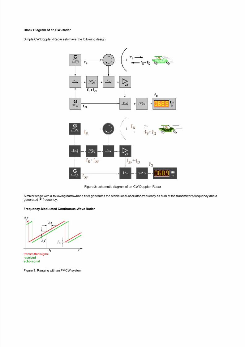
Block Diagram of an CW-Radar
Simple CW Doppler- Radar sets have the following design:
Figure 3: schematic diagram of an CW Doppler- Radar
A mixer stage with a following narrowband filter generates the stable local-oscillator-frequency as sum of the transmitter's frequency and agenerated IF-frequency.
Frequency-Modulated Continuous-Wave Radar
transmitted signalreceivedecho signal
Figure 1: Ranging with an FMCW system
5/12/2018 Continuous Wave Radar - slidepdf.com
http://slidepdf.com/reader/full/continuous-wave-radar 3/6
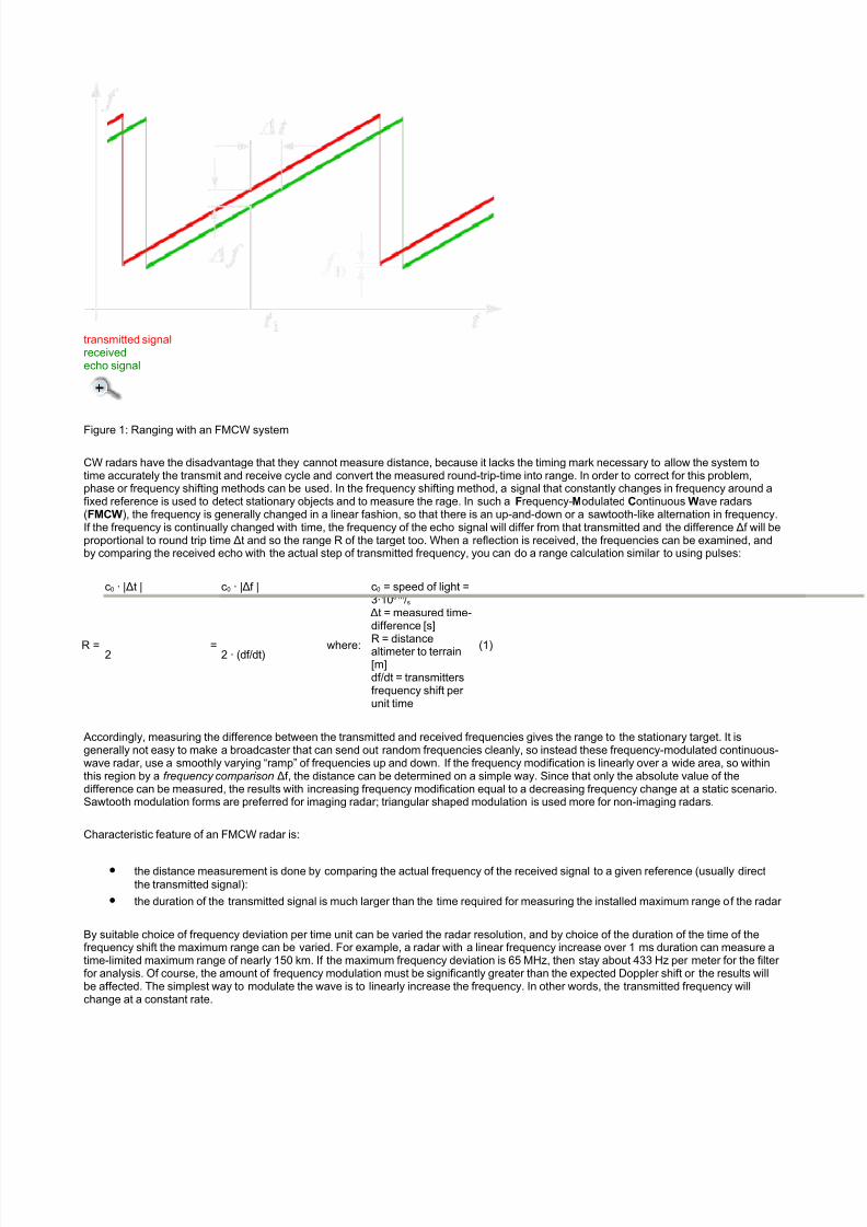
transmitted signalreceivedecho signal
Figure 1: Ranging with an FMCW system
CW radars have the disadvantage that they cannot measure distance, because it lacks the timing mark necessary to allow the system totime accurately the transmit and receive cycle and convert the measured round-trip-time into range. In order to correct for this problem,phase or frequency shifting methods can be used. In the frequency shifting method, a signal that constantly changes in frequency around afixed reference is used to detect stationary objects and to measure the rage. In such a Frequency-Modulated Continuous Wave radars(FMCW), the frequency is generally changed in a linear fashion, so that there is an up-and-down or a sawtooth-like alternation in frequency.If the frequency is continually changed with time, the frequency of the echo signal will differ from that transmitted and the difference Δf will beproportional to round trip time Δt and so the range R of the target too. When a reflection is received, the frequencies can be examined, andby comparing the received echo with the actual step of transmitted frequency, you can do a range calculation similar to using pulses:
R =
c0 · |Δt |
=
c0 · |Δf |
where:
c0 = speed of light =3·108 m/s
Δt = measured time-difference [s]
R = distancealtimeter to terrain[m]df/dt = transmittersfrequency shift per unit time
(1)2 2 · (df/dt)
Accordingly, measuring the difference between the transmitted and received frequencies gives the range to the stationary target. It isgenerally not easy to make a broadcaster that can send out random frequencies cleanly, so instead these frequency-modulated continuous-wave radar, use a smoothly varying “ramp” of frequencies up and down. If the frequency modification is linearly over a wide area, so withinthis region by a frequency comparison Δf, the distance can be determined on a simple way. Since that only the absolute value of thedifference can be measured, the results with increasing frequency modification equal to a decreasing frequency change at a static scenario.Sawtooth modulation forms are preferred for imaging radar; triangular shaped modulation is used more for non-imaging radars.
Characteristic feature of an FMCW radar is:
• the distance measurement is done by comparing the actual frequency of the received signal to a given reference (usually direct
the transmitted signal):
• the duration of the transmitted signal is much larger than the time required for measuring the installed maximum range of the radar
By suitable choice of frequency deviation per time unit can be varied the radar resolution, and by choice of the duration of the time of thefrequency shift the maximum range can be varied. For example, a radar with a linear frequency increase over 1 ms duration can measure atime-limited maximum range of nearly 150 km. If the maximum frequency deviation is 65 MHz, then stay about 433 Hz per meter for the filter for analysis. Of course, the amount of frequency modulation must be significantly greater than the expected Doppler shift or the results willbe affected. The simplest way to modulate the wave is to linearly increase the frequency. In other words, the transmitted frequency willchange at a constant rate.
5/12/2018 Continuous Wave Radar - slidepdf.com
http://slidepdf.com/reader/full/continuous-wave-radar 4/6
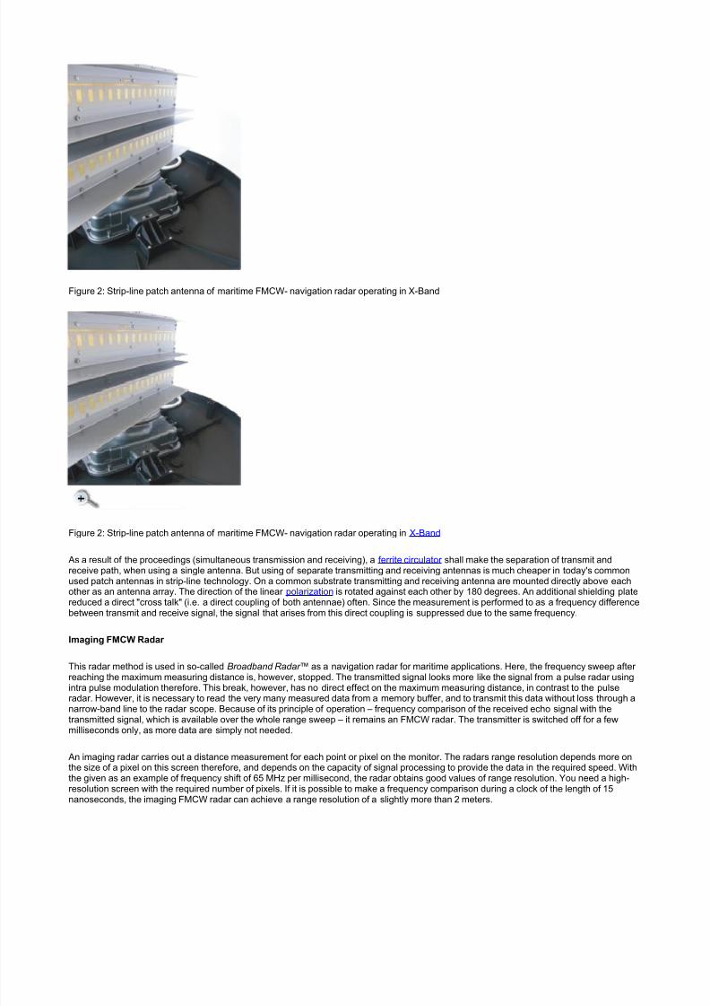
Figure 2: Strip-line patch antenna of maritime FMCW- navigation radar operating in X-Band
Figure 2: Strip-line patch antenna of maritime FMCW- navigation radar operating in X-Band
As a result of the proceedings (simultaneous transmission and receiving), a ferrite circulator shall make the separation of transmit andreceive path, when using a single antenna. But using of separate transmitting and receiving antennas is much cheaper in today's commonused patch antennas in strip-line technology. On a common substrate transmitting and receiving antenna are mounted directly above eachother as an antenna array. The direction of the linear polarization is rotated against each other by 180 degrees. An additional shielding platereduced a direct "cross talk" (i.e. a direct coupling of both antennae) often. Since the measurement is performed to as a frequency differencebetween transmit and receive signal, the signal that arises from this direct coupling is suppressed due to the same frequency.
Imaging FMCW Radar
This radar method is used in so-called Broadband Radar ™ as a navigation radar for maritime applications. Here, the frequency sweep after reaching the maximum measuring distance is, however, stopped. The transmitted signal looks more like the signal from a pulse radar usingintra pulse modulation therefore. This break, however, has no direct effect on the maximum measuring distance, in contrast to the pulse
radar. However, it is necessary to read the very many measured data from a memory buffer, and to transmit this data without loss through anarrow-band line to the radar scope. Because of its principle of operation – frequency comparison of the received echo signal with thetransmitted signal, which is available over the whole range sweep – it remains an FMCW radar. The transmitter is switched off for a fewmilliseconds only, as more data are simply not needed.
An imaging radar carries out a distance measurement for each point or pixel on the monitor. The radars range resolution depends more onthe size of a pixel on this screen therefore, and depends on the capacity of signal processing to provide the data in the required speed. Withthe given as an example of frequency shift of 65 MHz per millisecond, the radar obtains good values of range resolution. You need a high-resolution screen with the required number of pixels. If it is possible to make a frequency comparison during a clock of the length of 15nanoseconds, the imaging FMCW radar can achieve a range resolution of a slightly more than 2 meters.

5/12/2018 Continuous Wave Radar - slidepdf.com
http://slidepdf.com/reader/full/continuous-wave-radar 5/6
Non-Imaging FMCW Radar
Figure 3: Analog indicator of a radar altimeter
The measurement result of this FMCW radar is shown as a numerical value on a moving coil meter or digitized as alpha-numeric symbols ona screen. It can only be a single dominant object to be measured, but of this with a much high degree of accuracy down to the centimeter range. The most common form of FMCW radar is the radar altimeter used on aircraft to determine height above the ground, especially duringthe landing procedure of aircraft.
A possible Doppler frequency f D is displayed on the moving coil meter as a measuring error. The gradient of the slope can be chosen that theinfluence of the Doppler frequency is very small in contrast to the measured frequency difference. An analysis of the Doppler frequency ispossible by using a triangular shaped modulation and a separate frequency comparison during the rising and falling side of the triangleshaped modulation. For a reflective object with a positive (moving towards the radar) radial velocity the entire received signal will be movedby the Doppler frequency to higher frequencies. Compared to a fixed reflector, the frequency difference between transmit and receive signalson the rising edge of the triangle is reduced by the Doppler frequency and increased on the falling edge by the Doppler frequency. Thedifference between the two difference frequencies is therefore twice the Doppler frequency. Since both of difference frequencies are notavailable simultaneously, therefore this comparison, however, requires a digital signal processing.
Radar Basic Principles
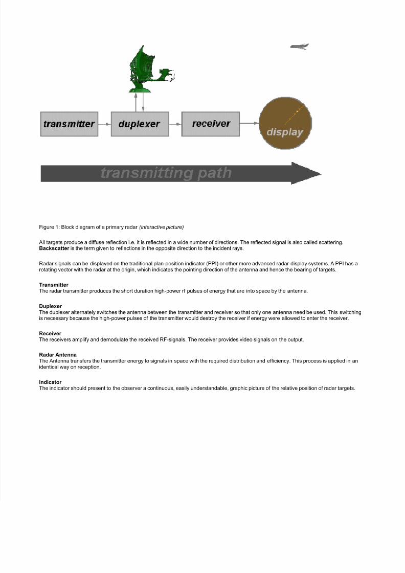
The following figure shows the operating principle of a primary radar set. The radar antenna illuminates the target with a microwave signal,which is then reflected and picked up by a receiving device. The electrical signal picked up by the receiving antenna is called echo or return.The radar signal is generated by a powerful transmitter and received by a highly sensitive receiver.
Figure 1: Block diagram of a primary radar
5/12/2018 Continuous Wave Radar - slidepdf.com
http://slidepdf.com/reader/full/continuous-wave-radar 6/6
Figure 1: Block diagram of a primary radar (interactive picture)
All targets produce a diffuse reflection i.e. it is reflected in a wide number of directions. The reflected signal is also called scattering.Backscatter is the term given to reflections in the opposite direction to the incident rays.
Radar signals can be displayed on the traditional plan position indicator (PPI) or other more advanced radar display systems. A PPI has arotating vector with the radar at the origin, which indicates the pointing direction of the antenna and hence the bearing of targets.
Transmitter The radar transmitter produces the short duration high-power rf pulses of energy that are into space by the antenna.
Duplexer The duplexer alternately switches the antenna between the transmitter and receiver so that only one antenna need be used. This switchingis necessary because the high-power pulses of the transmitter would destroy the receiver if energy were allowed to enter the receiver.
Receiver The receivers amplify and demodulate the received RF-signals. The receiver provides video signals on the output.
Radar AntennaThe Antenna transfers the transmitter energy to signals in space with the required distribution and efficiency. This process is applied in anidentical way on reception.
Indicator The indicator should present to the observer a continuous, easily understandable, graphic picture of the relative position of radar targets.