Embed Size (px)
Citation preview

Continuous-time Filtering:Modulation and AM Radio

Ideal filters
• distortion, signal power and bandwidth• filter classifications• impulse responses and causality
Communication systems
• radio transmission system: modulation• demodulation of AM signals• envelope detection of AM signals
Topics

What is distortion? ‘Changing the shape’ of a signal
Multiplication of a signal by a constant (even a negative one)or shifting it in time do not change its shape
No Distortion Distortion
Ideal filters

Filters separate signals in one frequency range from signalsin another frequency range
An ideal filter passes all signal power in its passbandwithout distortion and completely blocks signal poweroutside its passband
Ideal filters

Filter Classifications
FT analysis
The Fourier Transform of a signal is
For real-valued signals:
Fourier Transforms provide a different perspectiveon a signal. Some aspects become more evident inthe frequency domain.
!
f (t) =1
2"F( j#)e j#t
d#$%
+%
& ' ( ) F( j#) = f (t)e$ j#t
dt$%
+%
&
!
f (t) =1
"|F( j#) | cos(#t +$F( j# ))dt
0
+%
&

Signal energy
The signal energy can be computed in the time domain or inthe frequency domain.
This is Parseval’s Theorem:
Most of the energy of physical signals is concentrated in parts ofthe spectrum.
Example: Humans cannot hear above 20 KHz. Hence the usefulpart of audio signals have frequencies below 20 KHz. Wesay that audio signals are low-pass signals and have abandwidth of 20 KHz.
!
f (t)2dt =
"#
+#
$1
2%F( j&)
2d&
"#
+#
$

Signal bandwidth
Bandwidth means “range of frequencies.” We use it denote rangewhere most of signal energy is concentrated
E.g., for a low-pass signal, frequency such that
For r = 0.99, we say that is the 99% bandwidth of the signal.
For band-pass signal, frequency range such that
For r = 0.99 then we say that is the 99% bandwidth ofthe signal.
!
1
2"F( j#)
2d#
$%
+%
& = r1
2"F( j#)
2d#
$'
+'
&
!
"
!
"
!
1
"F( j# )
2d#
+$ l
+$u
% = r1
2"F( j# )
2d#
&'
+'
%
!
" ="u#"
l

Why are ideal filters called ideal?
One reason is that perfect circuit components with ideal characteristicsdo not exist
Another, more fundamental, reason can be seen in the correspondingimpulse responses
All responses have nonzero response before the impulse is applied at
!
t = 0

Ideal filters are non-causal
For example, ideal lowpass filter has a frequency response
The inverse Fourier transform is the impulse system response
!
H( f ) = A rect( f /2 fm )e" j2#ft0
!
h(t) = 2Afmsinc(2 fm (t " t0))
Non-causal system!
Ideal filters cannot bephysically realized, butthey can be closelyapproximated
Ideal filters
• distortion, signal power and bandwidth• filter classifications• impulse responses and causality
Communication systems
• radio transmission system: modulation• demodulation of AM signals• envelope detection of AM signals
Topics

What is modulation?
Modulation is the process of shifting the frequency of a signalso that the resulting signal is in a desired frequency band
Why would one be interested in modulation?1. Antenna length requirements: for efficient radiation, antenna
length is 1/2 or 1/4 of the wavelength to be radiated
Here, c is the speed of light. At a frequency of 1 KHz (humanvoice), a 1/4 wavelength antenna would measure
However, had the signal higher frequency, smaller antennaswould do
!
"c =c
fc
!
L =c
4 fc=3 "10
8
4 "103
=3
410
5= 75km

Why modulation?
Why would one be interested in modulation?2. Interference: two communications, at the same time and
over the same geographical area, using the samefrequency, would interfere with each other.
This can be solved by shifting information signals todifferent frequencies
Frequency band Designation Typical users
3-30 kHz Very low frequency (VLF) Long-range navigation
30-300 kHz Low frequency (LF) Marine communications
300-3000kHz Medium frequency (MF) AM radio broadcasts
3-30 MHz High frequency (HF) Amateur radio; telephone
30-300 MHz Very high frequency (VHF) VHF TV; FM radio
0.3-3 GHz Ultrahigh frequency (UHF) UHF TV; radar
3-30 GHz Superhigh frequency (SHF) Satellite communications
FCC Frequency Band Assignments

Modulation and Radio
A simplified radio communication system can be the following:
Music, people talking produces the input signal
In the transmitter, the signal is modulated, here as an amplitudemodulated (AM) signal
The frequency is the carrier frequency of the radio station.
Usually , where is the bandwidth of
!
x(t " t0)
!
x(t)
!
cos("ct)
!
cos("c(t # t
0))
!
x(t)
!
x(t)cos("ct)
!
"c
!
"c# $
!
"
!
"
!
"
!
x(t)

Modulation and Radio
A simplified radio communication system can be the following:
The radio signal is broadcast and picked up by the antenna on thereceiver.
The receiver converts down the broadcast signal (demodulates) intoa signal proportional to with a small time delay (lessthan a millisecond)
!
x(t " t0)
!
x(t)
!
cos("ct)
!
cos("c(t # t
0))
!
x(t " t0)
!
t0
!
"
!
"
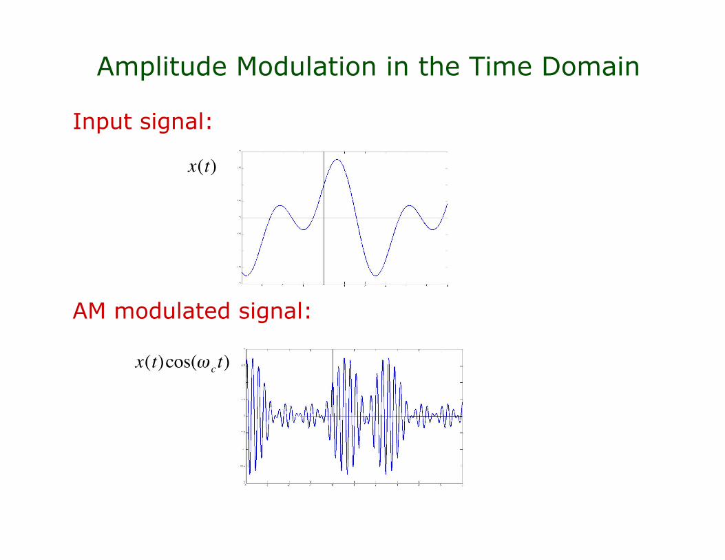
Amplitude Modulation in the Time Domain
Input signal:
AM modulated signal:
!
x(t)
!
x(t)cos("ct)

Amplitude Modulation in the Frequency Domain
Input signal:
AM modulated signal:
!
x(t)" # $ X( f )
!
x(t)cos(2"fct)# $ % Y ( f ) = X( f ) * 1
2&( f ' fc ) + 1
2&( f + fc )( ) = 1
2X f ' fc( ) + 1
2X f + fc( )

Modulation and Fourier Transform
Different AM stations have different carrier frequenciesIn the US, the carrier frequency is chosen from a set spaced10 KHz apart. These are taken within the frequency rangethat starts at 540 KHz and ends at 1700 KHz.
With a 10 KHz operation bandwidth, each AM station canbroadcast a signal of 5 KHz bandwidth.

Comparison with Frequency Modulation (FM)
Comparison of a signal and an FM version of it:
FM transforms a signal into another with higher-frequency bandbut unit magnitude
Stations range from 88 MHz to 108MHz at 200 KHz apartBandwidth of each station is only 15 KHzFM Antenna is only
!
L =c
4 fc=3 "10
8
4 "108
=3
4= 0.75m
!
cos "c
+ #x(t)( )t( )
!
x(t)

Other types of Modulation
In general, modulation is a process that changes one or moreproperties of a periodic signal (its amplitude, its frequency orits phase) by another signal
In the previous examples, the modulated, periodic signal is acos function, while the modulating signal is the radio wavesignal that we would like to transmit
Instead of cos, other periodic signals can be used. For example,using a pulse wave instead of a cosine wave results intopulse modulation.
Pulse modulation is used to transfer analog signals as digitalsignals (that is, as a sampled and quantized signal) by usinga digital transmission system

Ideal filters
• distortion, signal power and bandwidth• filter classifications• impulse responses and causality
Communication systems
• radio transmission system: modulation• demodulation of AM signals• envelope detection of AM signals
Topics

Coherent Demodulation of AM signals
An antenna for an AM radio receiver captures signals from tensof radio stations. How does it select the right signal?
The receiver uses a band-pass filter with an adjustable pass-band to tune in
The band-pass output is then converted into an audio signalthat is proportional to . Here, is the time delay ofthe propagation channel
!
f (t)
!
cos("ct)
!
cos("c(t # t
0))
!
f (t " t0)
!
f (t)cos("ct)
!
f (t " t0)
!
t0
!
"
!
"

Coherent demodulation of AM signals
The receiver input will be a signal
The receiver output will be a signal
The Fourier Transform of m(t) is
The first term of M(jw) is the signal we would like to recover
!
r(t) = kf (t " t0)cos(#c (t " t0))
!
M( j") =k
2F( j")e# j"t0 +
k
4F j " # 2"c( )( ) + F j " + 2"c( )( ){ }e# j"t0!
m(t) = r(t)cos "c (t # t0)( )
=k
2f (t # t
0){1+ cos(2"c (t # t0))}

Coherent demodulation of AM signals
Graphically, we have
In the final step,we take
!
r(t)" R(#)!
f (t)" F(#)
!
m(t)"M(#)
!
|F(") |
!
|R(") |
!
HLPF(")
!
|M(") |
!
"#c
!
"#c
!
"#c
!
"#c
!
"2#c
!
"2#c
!
"2#c
!
"2#c
!
2"c
!
2"c
!
2"c
!
2"c
!
"c
!
"c
!
"c
!
"c
!
1
!
k /2!
k /2
!
1
!
Y (") = HLPF(")M(")

Coherent demodulation of AM signals
After taking , we obtain
What happens if the receiver multiplies the broadcast signal
By with ?
For optimal demodulation the receiver must know exactly thevalue , hence the term coherent demodulation.
To avoid the estimation of an accurate , another processcalled envelope detection is used in practice
!
Y (") = HLPF(")M(")
!
y(t)"Y (#)
!
y(t) =k
2f (t " t
0)
!
t0
!
t0
!
r(t) = kf (t " t0)cos(# c (t " t0))
! !
t1" t
0
!
cos("c(t # t
1))
!
m(t) = r(t)cos " c (t # t1)( )
=k
2f (t # t
0){cos(" c (t0 # t1)) + cos(2" c (t # t0 + t
1))}

Ideal filters
• distortion, signal power and bandwidth• filter classifications• impulse responses and causality
Communication systems
• radio transmission system: modulation• demodulation of AM signals• envelope detection of AM signals
Topics

Recall AM Signal in Time Domain
Input Signal: AM Modulated Signal:
Envelope of signal is proportional to
!
f (t)
!
f (t)cos("ct)
!
f (t)

Recall AM Signal in Time Domain
Input Signal: AM Modulated Signal:
Envelope of signal is proportional to
!
( f (t) +")cos(#ct)
!
f (t) +" =| f (t) +" |
!
" >max | f (t) |
!
f (t) +" =| f (t) +" |

Envelope detection of AM signals
In order to implement envelope detection at the AM receiver,the AM transmitter is modified as follows
!
f (t)
!
"
!
cos("ct)
!
( f (t) +")cos(#ct)
!
+
!
"
!
" >max | f (t) |

Envelope detection of AM signals
The AM receiver will extract the signal as follows
!
r(t) = ( f (t) +")cos(#ct)
!
p(t) =| r(t) |
!
p(t)
!
q(t) = f (t) +"
!
HLPF(")
!
q(t) = f (t) +"
Envelope detection of AM signals
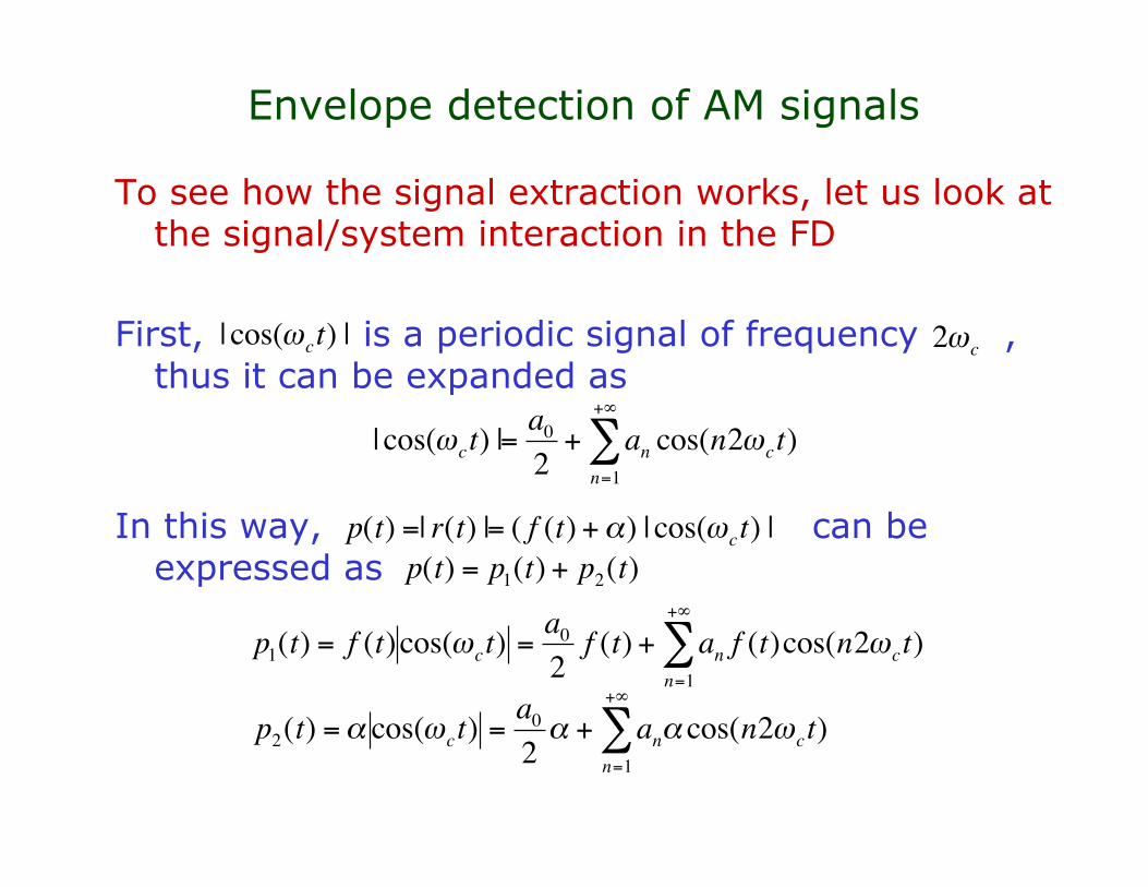
To see how the signal extraction works, let us look atthe signal/system interaction in the FD
First, is a periodic signal of frequency ,thus it can be expanded as
In this way, can beexpressed as
!
| cos("ct) |
!
2"c
!
| cos("ct) |=
a0
2+ a
ncos(n2"
ct)
n=1
+#
$
!
p(t) =| r(t) |= ( f (t) +") | cos(#ct) |
!
p(t) = p1(t) + p
2(t)
!
p1(t) = f (t)cos("ct) =
a0
2f (t) + an f (t)cos(n2"ct)
n=1
+#
$
!
p2(t) =" cos(#ct) =
a0
2" + an" cos(n2#ct)
n=1
+$
%

Envelope detection of AM signals
Now, consider that is designed in such a way that
Then, the response of to is justTo determine the filter response to , first we obtain
Because only the first term is within the pass-band of the filterwe just obtain
Therefore, using superposition, we find the output of
!
HLPF(")
!
p2(t)
!
HLPF(0) =
2
a0
!
HLPF(n2"
0) = 0
!
n "1
!
HLPF(")
!
q2(t) ="
!
p1(t)
!
P1(") =
a0
2F(") +
an
2{F(" # n2"
c) + F(" + n2"
c)}
n=1
+$
%
!
HLPF(")
!
Q1(") =
a0
2H(0)F(")# q
1(t) = f (t)
!
q(t) = q1(t) + q
2(t) = f (t) +"
!
HLPF

Envelope detection of AM signals
!
f (t)" F(#)
!
r(t)" R(#)
!
p(t)" P(#)
!
Q(") = HLPF(")P(")
!
HLPF(")
Graphically, we have
In the final step,we take
!
|F(") |
!
|R(") |
!
|P(") |
!
"#c
!
"2#c
!
2"c
!
"c
!
"#c
!
"2#c
!
2"c
!
"c
!
"#c
!
"2#c
!
2"c
!
"c
!
"#c
!
"2#c
!
2"c
!
"c

Envelope detection of AM signals
The process of envelope detection is insensitive totime shifts in the carrier wave
In other words, if the input to the detector is
The detector output will still be becausethe coefficients of the CTFS of donot change with a shift in time
!
r(t) = ( f (t " t0) +#)cos($c (t " t0))
!
f (t " t0) +#
!
| cos("c(t # t0)) |

Modulation and AM Radio Summary
Radio and Communication Systems can be better understood inthe Frequency Domain and by looking at signals spectra:
Before transmitting, signals need to be transformed from low-pass to band-pass signals.
-This is done by; e.g. AM modulation: or
At the receiver, signals are detected using demodulation and alow-pass filter. We discussed here two approaches:
- Coherent detection
- Envelope detection
!
f (t)
!
( f (t) +")cos(#ct)
!
f (t)cos("ct)
!
m(t) = r(t)cos("c(t # t
0))
!
r(t)
!
HLPF(")
!
r(t)
!
p(t) =| r(t) |
!
HLPF(")
!
k
2f (t " t
0)
!
f (t " t0) +#

Applications to radio-controlled devices
At its core, we have seen that radio is a very simple technology,yet the impact of radio in our society is tremendous. Some ofthe technologies that depend on radio include the following:
AM and FM radioCordless phonesGarage door openersTV remote controlWireless networksRadio-controlled toysGPS receiversSatellite communications…
Note that radio waves not only can be used to transmitinformation, but also that this information can be used forremote control

Applications to radio-controlled devices
A simplified block diagram of a remotely controlled toy is thefollowing:
By turning a knob in the joystick, an electric circuit is closed. Thiscircuit is connected to an Integrated Circuit which generates thesignal to be transmitted. It is possible to generate different signals
Before transmission, the signal is pulsed-modulated, to place the signalfrequencies in a range anywhere between to
!
27MHz
!
49MHz

Applications to radio-controlled devices
At the other end, the truck receiver is constantly monitoring forincoming signals
The picked signals are passed through a band-pass filter to block outthe frequencies outside the chosen frequency range
The obtained pulse sequence is then sent to an Integrated Circuit inthe truck. The IC decodes the sequence to generate the rightcontrol for the motor of the truck!