Embed Size (px)
Citation preview

Jiří Duspiva* – Ervín Hofmann** – Jaroslav Holý* – Pavel Král* – Milan Patrík*
* ÚJV Řež, a. s.
** ČEZ, a.s.
Continuous Process of Safety
Enhancement in Operation of Czech
VVER Units
Outline
Introduction
Systematic and focused approach to new safety measures
Examples and case studies of safety assessment
– Implementation of DEC-A concept
– Analytical support of severe accident strategies and measure
implementation
Conclusions
Introduction
A safety enhancement process - at both VVER sites in CR
– a continuous effort since commissioning
Significantly increased safety level
– within systematic and focused process
Despite the high level of safety
reached mainly by preventive means
– a new period of enhancement process has been initiated
following the Fukushima accident
Systematic and focused approach to new safety
measures
A special attention to mitigative part of potential accidents
– and relevant strategies and safety measures
Important attributes for new preventive safety measures
– diverse and alternative (mobile) means
diverse power sources, RCS/SFP/CNTM make up, alternative heat
sink, alternative key parameters monitoring, etc.
Analytical support
– Use of probabilistic and deterministic methods, and their
combination
Systematic and focused approach to new safety
measures
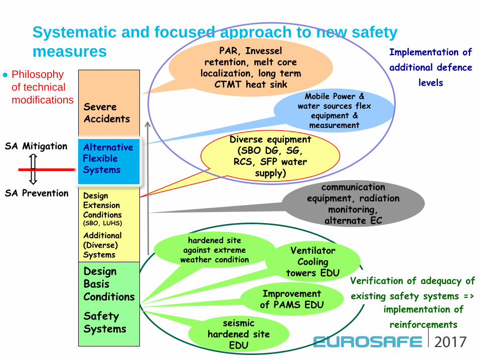
Philosophy
of technical
modifications
5
SA Prevention
SA Mitigation
Design Basis Conditions
Safety Systems
Severe Accidents
Design Extension Conditions (SBO, LUHS)
Additional (Diverse) Systems
Alternative Flexible Systems
seismic hardened site
EDU
Improvement of PAMS EDU
hardened site against extreme weather condition
PAR, Invessel retention, melt core
localization, long term CTMT heat sink
Mobile Power & water sources flex
equipment & measurement
Diverse equipment (SBO DG, SG, RCS, SFP water
supply)
communication equipment, radiation
monitoring, alternate EC
Implementation of
additional defence
levels
Verification of adequacy of
existing safety systems =>
implementation of
reinforcements
Ventilator Cooling
towers EDU

Systematic and focused approach to new safety
measures
Stress test outcomes resulted in several plant modifications in
prevention of severe accident – similar approach at both NPPs
Dukovany NPP as example
Seco
ndary
heat
sink
RCS / SFP / CNTM make-up
Diverse power source

Systematic and focused approach to new safety
measures
PSA has been recognized as a very useful tool
– within the process of safety enhancement
used mainly for identification of weak points and prioritization
– of safety measures
– additional cooling towers at Dukovany site
example of the measure proposed by external hazard PSA
– ultimate heat sink problem
• as a consequence of external events of high density (high wind with
return period 10 000 years)

Examples and Case Studies of Safety Assessment
Implementation of Design Extension Conditions
Analytical support of Severe Accident Strategies
– and particular safety measures implementation
Implementation of DEC-A Concept
When speaking about safety assessment of design extension conditions, i.e. analyses of events
beyond design basis accident (DBA), one should distinguish between analyses of DEC without
core melt (named DEC-A in the paper) and analyses of DEC with core melt (marked DEC-B in
the paper).
Whereas the later (DEC-B, severe accidents) have been widely assessed and analysed for at
least 2 decades with the accelerator moment of Chernobyl accident, the former (DEC-A, BDBA)
were analysed in the past only partially – typically only the anticipated transient without scram
(ATWS) and station blackout (SBO) were analysed and documented in Safety Analysis Report.
The more systematic work on safety assessment of DEC-A (BDBA) has been started only in the
last decade with different starting point and speed in various countries. This effort has been
initiated by initiatives and suggestions of European Utility Requirements (EUR), WENRA safety
reference levels and IAEA introducing DEC term and concept into the safety standards series
SSR-2/1 and GSR-Part4.
The work on BDBA and DEC-A safety analyses for Czech NPPs was initiated in 2009 as a
consequence of the Periodical Safety Review (PSR) after 20 year of the operation of the
Dukovany NPP. The safety assessment of DEC-A and implementation of DEC concept in whole
is based on recommendation from the IAEA, WENRA and EUR documents mentioned above.
For the DEC-A safety analyses themselves the requirements of SUJB “Safety Guide BN-JB-1.7
Selection and Evaluation of Design and Beyond Design Events and Risks for NPP, 2010” has
been applied.

Implementation of DEC-A Concept
Approach to DEC-A analyses:
Selection of DEC-A (BDBA) events to be analyzed based on requirements of BN-JB-1.7 plus supplements according to PSA
In selection based on PSA, transfer from “frequency of occurrence of initiating event” to “frequency of occurrence of scenarios”
Realistic computer codes, models and analysis assumptions
Acceptance criteria same as for DBA (with exceptions like higher system pressure AC)
Majority of DEC-A analyses for the Czech NPP’s Dukovany and Temelin have been done with help of RELAP5 computer code
In UJV Rez the RELAP5 has been validated against experimental data from more than 20 tests carried out at various integral and separate test facilities.
Approximately half of these tests were events of DEC-A type
All computer codes to be used for safety analyses in the Czech Republic must be reviewed and licensed according to regulatory body (SUJB) directive VDS-030
Implementation of DEC-A Concept
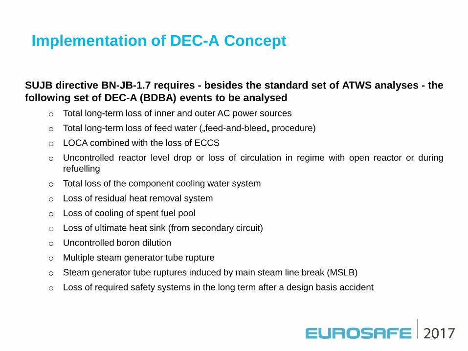
SUJB directive BN-JB-1.7 requires - besides the standard set of ATWS analyses - the
following set of DEC-A (BDBA) events to be analysed
o Total long-term loss of inner and outer AC power sources
o Total long-term loss of feed water („feed-and-bleed„ procedure)
o LOCA combined with the loss of ECCS
o Uncontrolled reactor level drop or loss of circulation in regime with open reactor or during
refuelling
o Total loss of the component cooling water system
o Loss of residual heat removal system
o Loss of cooling of spent fuel pool
o Loss of ultimate heat sink (from secondary circuit)
o Uncontrolled boron dilution
o Multiple steam generator tube rupture
o Steam generator tube ruptures induced by main steam line break (MSLB)
o Loss of required safety systems in the long term after a design basis accident

Implementation of DEC-A Concept
1 2 4 5 6 7 1 03 98 1 1
1 2
1 3
2 1 2 2 2 3 2 5 2 6
2 7
2 0 2 4
2 8 2 9
3 0
9 0 9
9 1 1 9 1 3
PSK 2
1 4
1 8
1 7
1 6
1 5
1 9
025
1
2 3
4
916
026
1
2 3
4
918
027
1 8765432
9
1 0 1 1 1 2 1 3
1 5
1 4
1 9 2 0 2 1 2 2 2 3 2 41 81 71 6
2 5
2 6 2 7
2 8
9 1 79 1 9
9 1 5
PSK 1
1 2 3 4 5 6 7 8
9
1 0 1 1 1 2
182
186
TG 4
990
989
900
904
901
902
022
1
2
3 4
5
910
023
1
2
3 4
5
912
024
1 2 3 4 5 6 7 8 9
1 0
1 21 1
382
386
928
488
487
489490 491
492
484
021
485 483
019
486
1 2
1 11 09
8
76543
482
020
929
9 0 3
H PK
RCA+z pe t . kl apka
PG 1
SV1 SV2
PSV
TG 1
PG 2
RCA+z pe t . kl apka
SV1 SV2 PSV
TG 2
PG 3
SV1 SV2 PSV
RCA+z pe t . kl apka
TG 3
SV1 SV2 PSV
PG 4
RCA+z pe t . kl apka
188
187
189190
192
011
184
177
1
2
3
4
5
6
012
185
178
1
2
3
4
5
6
183
2 3
7
4
65
8
1
9
179
010
191
926
286
288
287
289290 291
2921 2 3 4 5 6 7 8 9 1 0
1 1
1 2
282
014
284
015
285 283
013
927
388
387
389390 391
392
017
384
018
385 383
016
2
3
4
5
RZV
1
2
3
4
1 41 3
5
1
RZV
1
914
2
3
4
5
2
3
1 3
908
4
5
RZV
RZV
1
Nodalization of VVER-1000 for RELAP5
Active
ECCS
(1/3)
Containment
Main steam
system
Primary circuit
(1/4)
Input model statistics:
1800 control volumes
2400 hydraulic junctions
1600 heat structures with
8700 mesh points
2680 control variables
1110 trips
FW system

Implementation of DEC-A Concept
Example of DEC-A analysis for VVER-1000
Analysis of small break loss of coolant accident (SBLOCA) with break D50 mm
in cold leg and without Primary Reactor Protection System (PRPS) which lead
among other to failure of start of emergency core cooling systems (ECCS)
Reactor is scrammed by DPS
Operator manual start of high pressure safety
injection (HPSI) at 30 min
Calculation performed with RELAP5 computer
code and detailed input model of VVER-1000
Implementation of DEC-A Concept
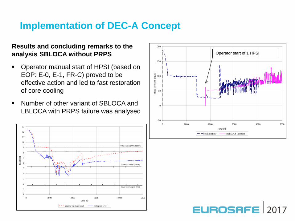
Results and concluding remarks to the
analysis SBLOCA without PRPS
Operator manual start of HPSI (based on
EOP: E-0, E-1, FR-C) proved to be
effective action and led to fast restoration
of core cooling
Number of other variant of SBLOCA and
LBLOCA with PRPS failure was analysed
-50
0
50
100
150
200
0 1000 2000 3000 4000 5000
time [s]
mass
flo
wra
te [
kg/s
]
break outflow total ECCS injection
0
1
2
3
4
5
6
7
8
9
10
11
12
13
0 1000 2000 3000 4000 5000
time [s]
level
[m]
reactor mixture level collapsed level
Outlet nozzles (9.108/8.258 m)
Upper core margin (5.33 m)
Lower core margin (1.68 m)
Operator start of 1 HPSI

Implementation of DEC-A Concept
The whole set of prescribed DEC-A analyses was already performed both for
Dukovany NPP (VVER-440) and for Temelin NPP (VVER-1000). From 15 to 20 DEC-
A analyses for each plant
As for the documentation of DEC-A analyses in Safety Analysis Report, the
temporary solution was the creation of a new SAR subchapter 15.9.1 which
contains basic results of all DEC-A (BDBA) analyses required by BN-JB-1.7
Beside that the ATWS analyses are documented in subchapter 15.8 of the SAR as
usually
The final solution is introduction of new SAR chapter 19 that would contain both
DEC-A (BDBA without core melt) and DEC-B (severe accident) analyses presented
in systematic and integrated way
Then the Chapter 15 will contain only analyses of events ranging from normal
operation (NO) to design basis accident (DBA)
New chapter „19.2 DEC“ for Dukovany NPP is partly implemented to SAR, at
Temelin NPP is in progress

Implementation of SA Strategies and Measures
ÚJV Řež provides complex services in SAM to Czech NPPs owned and operated by
ČEZ a.s.
o Accident progression
o Evaluation of source terms
o Identification of severe accident management strategies
o Supporting analyses for optimization of SAM strategies
o Validation of existing SAMGs
o Supporting analyses for control room habitability
o Development of layout of hydrogen mitigation system for Temelin NPP
Stress test observations National Action Plan - SA main actions
o Increase of the capacity of the system for emergency hydrogen removal (A#46 – Dukovany NPP,
A#47 – Temelin NPP)
o Cooling of the melt from the outside of RPV (A#48 – Dukovany NPP)
o Recriticality (A#61 – both NPPs)
o Control room habitability (A# 58, 31, and 51 – both NPPs)
o The means for maintaining containment integrity due to overpressure (A# 46 – 50 – both NPPs)
o Corium in/ex vessel cooling (A# 48, 49, 50 – Temelin NPP)
o Extension of SAMGs for shutdown / severe accident in SFP (A#56 – for both NPPs)
o System setup of training (drills), exercises and training for severe accident management
according to SAMG, including possible solution of multi-unit severe accident (A#55 – both NPPs)

Implementation of SA Strategies and Measures
Analytical support of hydrogen removal system design
Project duration 2013-2015
Three main steps of methodology o Integral analyses of selected scenarios – determination of sources to
Cntn Integral model of Temelin NPP in MELCOR code
o Analyses of H2 risk based on Sigma and Lambda criteria in detailed Cntn
model o Detailed model of Cntn in MELCOR code
138 CVs, 348 FLs, 432 concrete and 147 steel HSs
External sources of masses, energy and fission products
o Optimization analyses of PAR layout – numbers, sizes and locations of
PARs – NIS supplier o Optimization criteria
Lambda criterion elimination
Sigma criterion elimination in most of nodes (temporary occurence in limited
space allowed)
Global and local hydrogen concentration (in dry air; local H2 < 10%dry,
global H2 < 8%dry, and PAICC < Pdesign + 1 bar)

Implementation of SA Strategies and Measures
Analytical support of hydrogen removal system design
Three main SA scenarios – 2 branches on MCCI – Additional case on variant location of LOCA break
Hydrogen spatial distribution evaluated with ATLAS postprocessor
two windows – variant parameters visualized including fulfillment of
Sigma and Lambda criteria
Temelin NPP already equipped with AREVA PARs on DBA – 22 AREVA units FR90/1-150
Newly proposed system with
109 equiv. NIS22 units – NIS22, 44, and 88 used in final
design
System based on analytical support
already installed and in operation
since 2015

Implementation of SA Strategies and Measures
Corium localization at Temelin NPP
Objective of corium localization – To restart heat removal from failed fuel and to stabilize containment
conditions with the aim to prevent (or minimize) FP releases
Time evolution of activities – From IE Prevention of SA
– From Entry to SA Mitigation of SA in RPV
– From LHF Mitigation of SA out of RPV
Temelin NPP already implemented several additional measures to
original project design for SA prevention (applicable also in
mitigation phase) – Diverse equipment (TB50 – water supply to RCS, SFP, and Cntn sprays)
– Alternative (mobile) equipment (mobile DG, T-joint, and mobile pump)

Implementation of SA Strategies and Measures
Corium localization at Temelin NPP
LHF is assumed as failure of alternative and diverse equipment
(cliff-edge effect) o Timing range of hours (depends on scenario)
o ? quantification of contribution of new equipment PSA PSA update is ongoing
o Requirements to new equipment for SA mitigation More simple than existing systems
Reduced requirements to operating staff and energy supply, etc.
o All of assumed retrofits for corium localization, up to now, are focused on
coolant injection into RPV/Cntn They open other issues of SAM
– Long term heat removal from Cntn, if design systems are un-available
(sprays, UJ system etc.)
– Removal of large mass of contaminated water from Cntn – processing and
storing
Implementation of SA Strategies and Measures
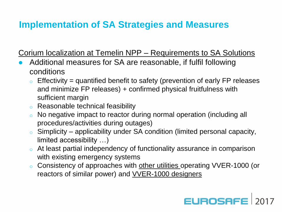
Corium localization at Temelin NPP – Requirements to SA Solutions
Additional measures for SA are reasonable, if fulfil following
conditions o Effectivity = quantified benefit to safety (prevention of early FP releases
and minimize FP releases) + confirmed physical fruitfulness with
sufficient margin
o Reasonable technical feasibility
o No negative impact to reactor during normal operation (including all
procedures/activities during outages)
o Simplicity – applicability under SA condition (limited personal capacity,
limited accessibility …)
o At least partial independency of functionality assurance in comparison
with existing emergency systems
o Consistency of approaches with other utilities operating VVER-1000 (or
reactors of similar power) and VVER-1000 designers

Implementation of SA Strategies and Measures
Corium localization at Temelin NPP
Three steps of possible solutions of corium localization
Early degraded core re-flooding (TMI-2 like scenario) (IVR-IN) o In case of limited duration of applicability – influence of conditions for
IVR-EX or ExVC solution to reduced decay power conditions
IVR with external RPV cooling (IVR-EX) (IVR-ERVC)
o Recently – Deflector for increase of CHF seems to be Necessary for physical feasibility
Unacceptable due to too much complicated conditions of installation and
removal during each of outage – too many risks
o Success, at least temporary, of previous IVR-IN can provide IVR-EX
physically feasible without deflector
Corium cooling outside of RPV (ExVC) (ExVR)
o Various approaches investigated due to mainly very high dose rates in
reactor cavity, which would significantly complicate any work there
Implementation of SA Strategies and Measures
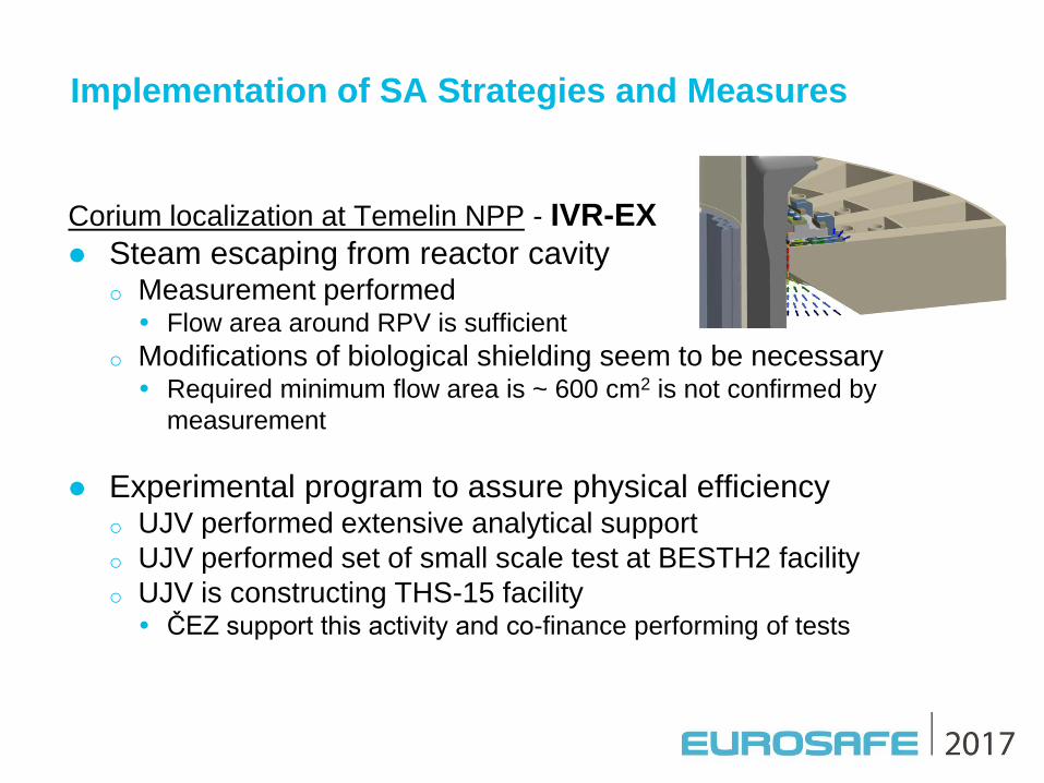
Corium localization at Temelin NPP - IVR-EX
Steam escaping from reactor cavity o Measurement performed Flow area around RPV is sufficient
o Modifications of biological shielding seem to be necessary Required minimum flow area is ~ 600 cm2 is not confirmed by
measurement
Experimental program to assure physical efficiency o UJV performed extensive analytical support
o UJV performed set of small scale test at BESTH2 facility
o UJV is constructing THS-15 facility ČEZ support this activity and co-finance performing of tests
Implementation of SA Strategies and Measures
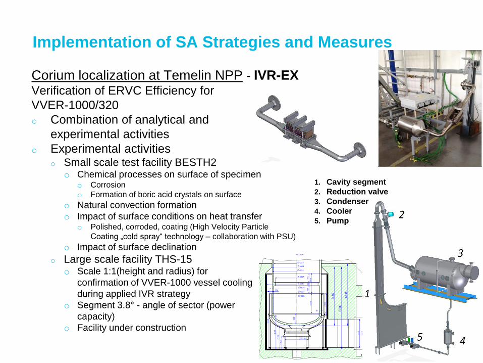
Corium localization at Temelin NPP - IVR-EX Verification of ERVC Efficiency for
VVER-1000/320
o Combination of analytical and
experimental activities
o Experimental activities o Small scale test facility BESTH2
o Chemical processes on surface of specimen o Corrosion
o Formation of boric acid crystals on surface
o Natural convection formation
o Impact of surface conditions on heat transfer o Polished, corroded, coating (High Velocity Particle
Coating „cold spray“ technology – collaboration with PSU)
o Impact of surface declination
o Large scale facility THS-15 o Scale 1:1(height and radius) for
confirmation of VVER-1000 vessel cooling
during applied IVR strategy
o Segment 3.8° - angle of sector (power
capacity)
o Facility under construction
1. Cavity segment
2. Reduction valve
3. Condenser
4. Cooler
5. Pump

Implementation of SA Strategies and Measures
Corium localization at Temelin NPP - IVR-EX
THS-15 … Thermal-Hydraulics Stand – initiated 2015
Implementation of SA Strategies and Measures
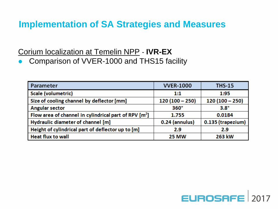
Corium localization at Temelin NPP - IVR-EX
Comparison of VVER-1000 and THS15 facility
Implementation of SA Strategies and Measures
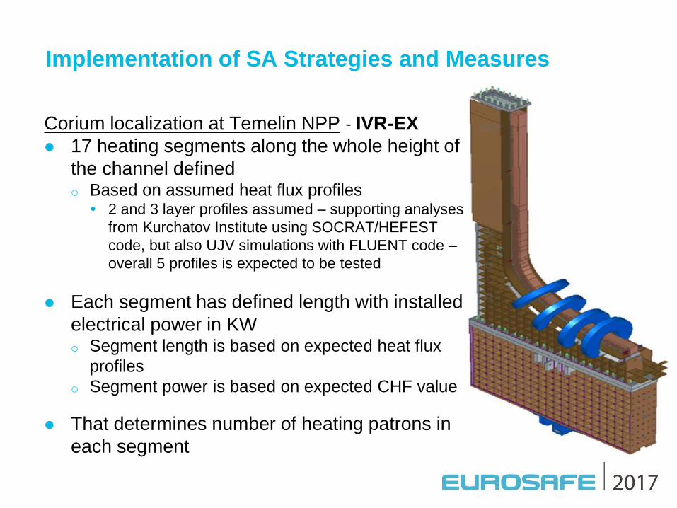
Corium localization at Temelin NPP - IVR-EX
17 heating segments along the whole height of
the channel defined o Based on assumed heat flux profiles 2 and 3 layer profiles assumed – supporting analyses
from Kurchatov Institute using SOCRAT/HEFEST
code, but also UJV simulations with FLUENT code –
overall 5 profiles is expected to be tested
Each segment has defined length with installed
electrical power in KW o Segment length is based on expected heat flux
profiles
o Segment power is based on expected CHF value
That determines number of heating patrons in
each segment
Implementation of SA Strategies and Measures
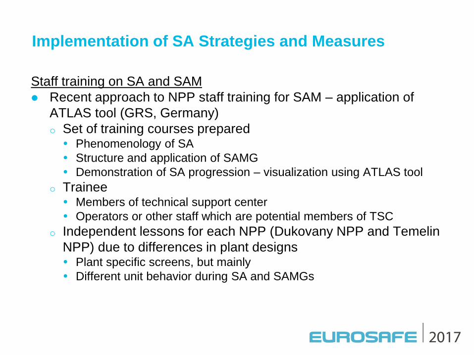
Staff training on SA and SAM
Recent approach to NPP staff training for SAM – application of
ATLAS tool (GRS, Germany)
o Set of training courses prepared Phenomenology of SA
Structure and application of SAMG
Demonstration of SA progression – visualization using ATLAS tool
o Trainee Members of technical support center
Operators or other staff which are potential members of TSC
o Independent lessons for each NPP (Dukovany NPP and Temelin
NPP) due to differences in plant designs Plant specific screens, but mainly
Different unit behavior during SA and SAMGs

Implementation of SA Strategies and Measures
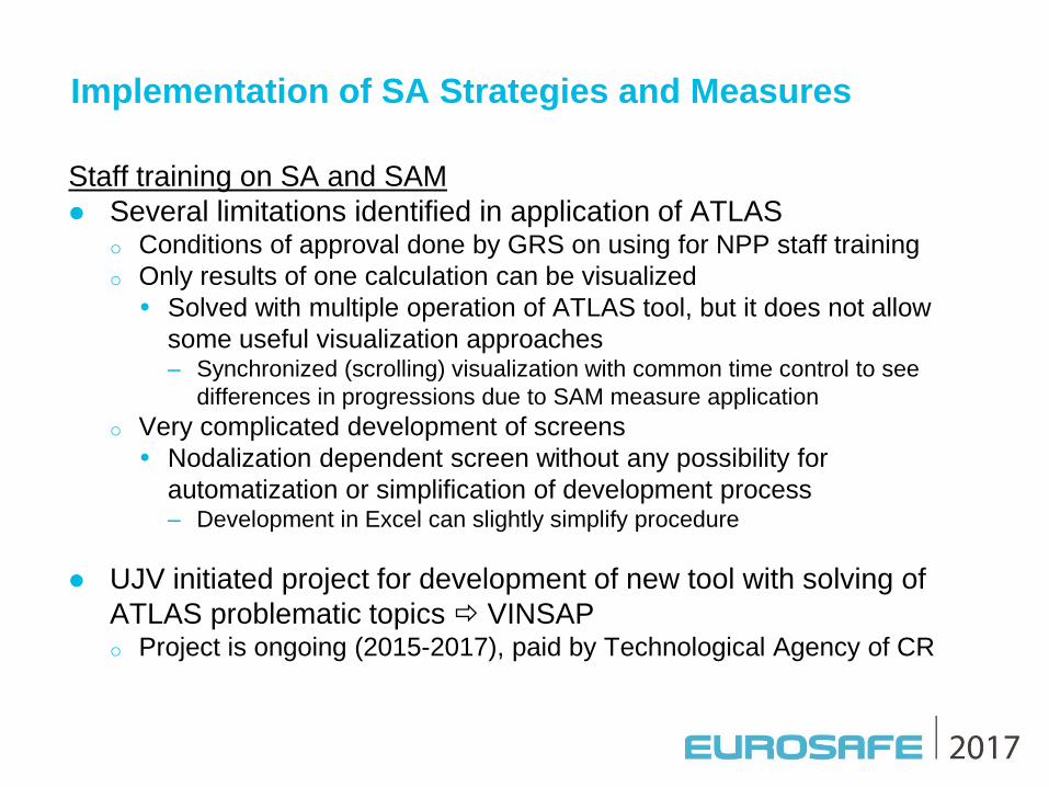
Staff training on SA and SAM
Example of ATLAS screens for Temelin NPP
Implementation of SA Strategies and Measures
Staff training on SA and SAM
Several limitations identified in application of ATLAS o Conditions of approval done by GRS on using for NPP staff training
o Only results of one calculation can be visualized
Solved with multiple operation of ATLAS tool, but it does not allow
some useful visualization approaches – Synchronized (scrolling) visualization with common time control to see
differences in progressions due to SAM measure application
o Very complicated development of screens
Nodalization dependent screen without any possibility for
automatization or simplification of development process – Development in Excel can slightly simplify procedure
UJV initiated project for development of new tool with solving of
ATLAS problematic topics VINSAP o Project is ongoing (2015-2017), paid by Technological Agency of CR

Implementation of SA Strategies and Measures
VINSAP Tool (Visualization of NPP Severe Accident Progress for
Training on SAM)
Development is done for visualization of MELCOR code results
(M186 and M2.2) o Due to transformation (conversion) of output file to specific database
format, the transformation tool can be modified to use VINSAP also for
other codes
Principal version is developed in Czech language, but all description
are called during compilation from one list, which can be translated
and alternative language version released o Recently also English mutation is prepared, some terms need to be
corrected as translation done by programmers, not SA specialist
Tool consists of 4 main utilities o Transformation
o Re-calculation
o Screen-editor
o Visualization Final utility for training
Utilities for results processing and
screen preparation

Implementation of SA Strategies and Measures
VINSAP – Primary Circuit Screen Example
Further
development
ongoing – User defined
color scales
Implementation of SA Strategies and Measures
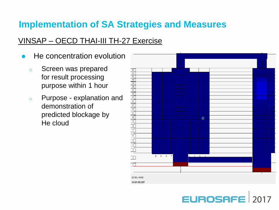
VINSAP – OECD THAI-III TH-27 Exercise
He concentration evolution
o Screen was prepared
for result processing
purpose within 1 hour
o Purpose - explanation and
demonstration of
predicted blockage by
He cloud

Conclusions
A systematic continuous effort of safety enhancement
– ongoing at both VVER sites in the Czech Republic
since commissioning
A Fukushima accident has initiated a new period
– of safety enhancement process
Implementation of diverse and alternative (mobile) means to prevent
SA
o became even more important attributes
Implementation of special means to eliminate progress and mitigate
SA phenomena
Advanced approaches in analytical support
– are being used within this systematic process