Embed Size (px)
Citation preview

The Furniss Corporation 800 273 5233 KneeCPM.com
Continuous Passive Motion Device (CPM)
Operator Manual
Phoenix Model 1800 Knee CPM Phoenix Model 1850 Knee CPM
DC2480 Knee CPM
The Furniss Corporation 800 273 5233 KneeCPM.com
FOREWARD This manual has been written for operators of the Furniss Corporation Continuous Passive Motion (CPM) Therapy Unit. It contains general information for operation, precautionary instructions and maintenance recommendations. In order to obtain maximum life and efficiency from your Furniss Corp CPM Unit, and to assist in the proper operation of the unit, read and understand this manual thoroughly. It is recommended that all clinicians and support personnel become familiar with the operating procedures, as well as the indications, contraindications, warnings and precautions prior to administering patient treatment.
Product Description Continuous Passive Motion is a postoperative procedure designed to aid in patient recovery after joint surgery, soft tissue surgical procedure or trauma. The treatment method has been practiced for more than 30 years. This unit is typically used postoperatively for total knee replacement and Anterior Cruciate Ligament (ACL) repairs. After extensive joint surgery patient attempts at joint flexion can cause considerable pain, dissuading the patient from effective joint motion. Failure to achieve proper rehabilitative flexion can lead to stiffening of the tissue around the joint. Eventually, this condition may cause intra-articular adhesions (formation of scar tissue) and extra-articular contractures (shortening of a muscle or tendon), resulting in a limited range of motion for the joint. Passive range of motion moves the joint gradually and slowly without the use of the patient’s muscles. The device is applied post-operatively and can be used in both inpatient and outpatient therapy regimens. The physician will prescribe usage instructions, including the speed of the machine, the duration of usage, amount of motion and the rate of motion increase. Various studies have concluded that patients using a CPM machine following surgery generally reduce the risk of complications and require less pain medication than those who do not use the CPM device after the same type of surgery.
About the Manufacturer As a US based medical manufacturer, The Furniss Corporation builds Continuous Passive Motion (CPM) devices for the upper and lower extremities. The durable, user friendly devices are built to withstand the rigorous hospital and home care environment. Furniss Corp also manufactures patient softgoods and offers a comprehensive technical service and repair center. Expect same-day shipping, immediate access to educated product professionals and strong product lines with exceptional performance. Visit the website at KneeCPM.com to experience the interactive tour.
The Furniss Corporation 800 273 5233 KneeCPM.com
PRECAUTIONARY INSTRUCTIONS
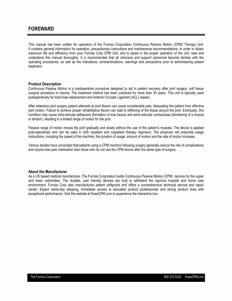
Read, understand and practice the precautionary instructions found in this manual before operating or using the unit. Know the limitations and hazards associated with using the device. Observe any and all precautionary and operational labels placed on the unit.
Do not use the Furniss Corp CPM device outdoors or on wet surfaces. Use only on firm, flat, level surfaces to ensure stability of the unit while in operation.
Extreme caution should be taken when in use with or around children.
Use the CPM device only for its intended purpose as described in this manual.
Turn power switch off before unplugging unit from its power source.
Do not touch any exposed or uninsulated wires or terminals unless the transformer has been unplugged.
Do not use the cord to unplug the power cord from the power source. Grasp at the power cord base. Use a surge protector to further safeguard the unit.
Transport and store the device in temperatures between –40 degrees Celsius to +70 degrees Celsius to prevent damage to the unit or its components. Condensation could result and damage the Furniss Corp CPM if unit is subjected to periods of low temperatures followed by periods of high temperatures. Additional environmental conditions include: relative humidity range within 10% to 100%. Atmospheric pressure range within 500 to 1060 hPa.
Use care when carrying, transporting or storing the device to prevent damage to the unit from dropping or improper transport and storage methods.
U.S. Federal law restricts this device to sale by, or on the order of, a physician or licensed practitioner.
Make certain that the unit is electrically grounded by connecting only to a grounded electrical service receptacle conform-ing to the applicable national and local electrical codes.
Keep obstructions such as hair, loose clothing, bedding, pets, fingers and toes away from the ballscrew assembly and hinge components of the unit.
The Furniss Corp CPM device must be completely visible at all times during use. Never cover the unit with bedding or any other means of concealment while in operation.
Do not use the Furniss Corp CPM device while smoking or around open flame.
Equipment no suitable for use in presence of a flammable anesthetic mixture with air, oxygen or nitrous oxide.
Precautionary measures should be taken when any type of liquid comes in contact with an electrical apparatus.
Always turn off and unplug unit from electrical source before servicing or cleaning. Failure to do so could result in electrical shock or personal injury.
Handle the unit only when the unit is dry and hands are dry to prevent electrical shock.
Unconscious patients or patients under heavy influence of medication must be constantly attended and monitored while the device is in use.
CAUTION
WARNING
The Furniss Corporation 800 273 5233 KneeCPM.com
UNPACKING YOUR CPM
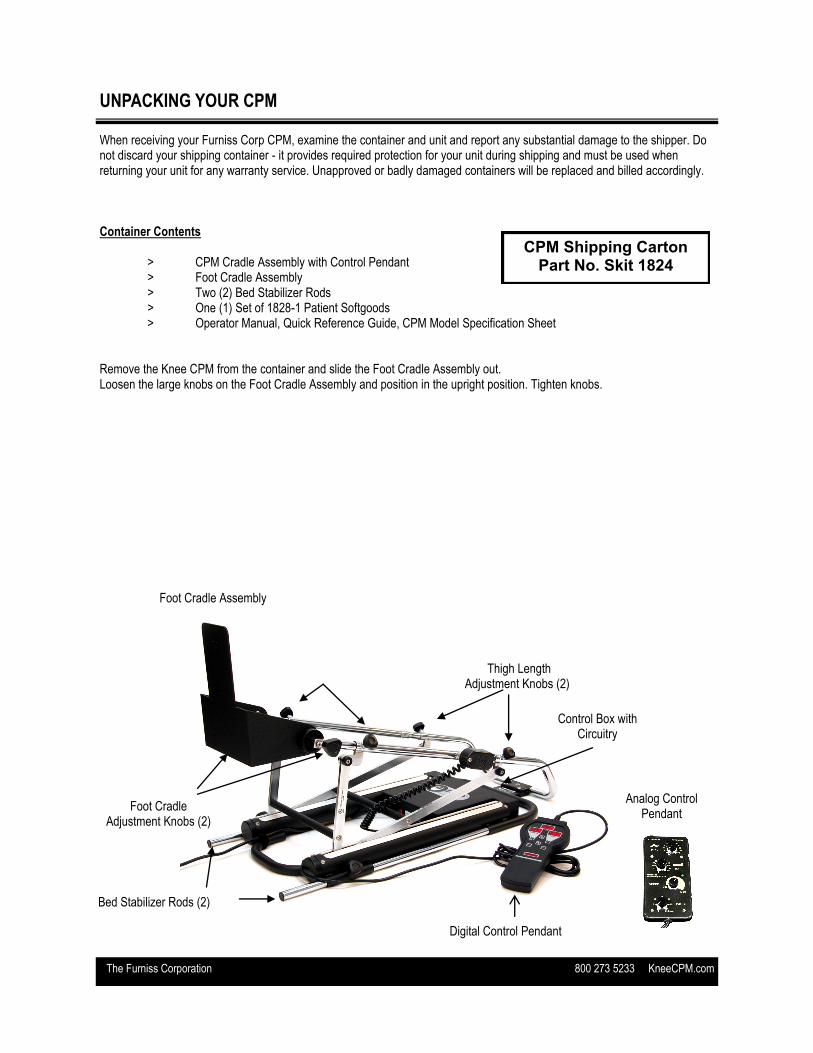
When receiving your Furniss Corp CPM, examine the container and unit and report any substantial damage to the shipper. Do not discard your shipping container - it provides required protection for your unit during shipping and must be used when returning your unit for any warranty service. Unapproved or badly damaged containers will be replaced and billed accordingly. Container Contents > CPM Cradle Assembly with Control Pendant > Foot Cradle Assembly > Two (2) Bed Stabilizer Rods > One (1) Set of 1828-1 Patient Softgoods > Operator Manual, Quick Reference Guide, CPM Model Specification Sheet Remove the Knee CPM from the container and slide the Foot Cradle Assembly out. Loosen the large knobs on the Foot Cradle Assembly and position in the upright position. Tighten knobs.
Foot Cradle Assembly
Foot Cradle Adjustment Knobs (2)
Thigh Length Adjustment Knobs (2)
CPM Shipping Carton Part No. Skit 1824
Bed Stabilizer Rods (2)
Digital Control Pendant
Control Box with Circuitry
Analog Control Pendant
The Furniss Corporation 800 273 5233 KneeCPM.com
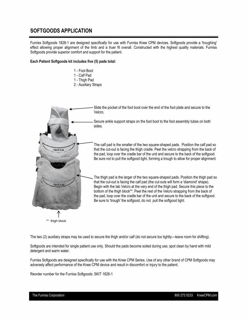
SOFTGOODS APPLICATION Furniss Softgoods 1828-1 are designed specifically for use with Furniss Knee CPM devices. Softgoods provide a 'troughing' effect allowing proper alignment of the limb and a truer fit overall. Constructed with the highest quality materials. Furniss Softgoods provide superior comfort and support for the patient. Each Patient Softgoods kit includes five (5) pads total: 1 - Foot Boot 1 - Calf Pad 1 - Thigh Pad 2 - Auxiliary Straps
The two (2) auxiliary straps may be used to secure the thigh and/or calf (do not secure too tightly—leave room for shifting). Softgoods are intended for single patient use only. Should the pads become soiled during use, spot clean by hand with mild detergent and warm water. Furniss Softgoods are designed specifically for use with the Knee CPM Series. Use of any other brand of CPM Softgoods may adversely affect performance of the Knee CPM device and result in discomfort or injury to the patient. Reorder number for the Furniss Softgoods: SKIT 1828-1
Slide the pocket of the foot boot over the end of the foot plate and secure to the Velcro. Secure ankle support straps on the foot boot to the foot assembly tubes on both sides. The calf pad is the smaller of the two square-shaped pads. Position the calf pad so that the cut-out is facing the thigh cradle. Peel the velcro strapping from the back of the pad, loop over the cradle bar of the unit and secure to the back of the softgood. Be sure not to pull the softgood tight, forming a trough to allow for proper alignment. The thigh pad is the larger of the two square-shaped pads. Position the thigh pad so that the cut-out is facing the calf pad (the cut-outs will form a 'diamond' shape). Begin with the tab Velcro at the very end of the thigh pad. Secure this piece to the bottom of the thigh block**. Peel the rest of the Velcro strapping from the back of the pad, loop over the cradle bar of the unit and secure to the back of the softgood. Be sure to 'trough' the softgood, do not pull the softgood tight.
TROUGH
TROUGH
** thigh block
The Furniss Corporation 800 273 5233 KneeCPM.com
PATIENT SETUP Correct measurement and adjustments are required to ensure patient comfort and compliance and to achieve desired range of motion. Check that the unit is at 0 degrees during patient setup. Note: Use only on a stable surface. An unstable surface could result in injury to patient and damage to the device. FITTING THE PATIENT
Determine the length of the patient’s femur by measuring from the greater trochanter (hip joint) to the center or joint line of the knee.
Transfer this measurement to the thigh cradle beginning approximately 1.5 to 2 inches away from the hip pivot assembly measuring to the knee axis of the unit. Adjust the thigh cradle to match this measurement by loosening the thigh adjustment knobs and sliding the thigh cradle to the proper length. Note: The DC2480 maximum cradle adjustment is 3 inches. Do not extended beyond this point. If patient’s thigh length exceeds these measurements, simply increase the beginning point of measurement to 4 to 6 inches away from the hip pivot assembly.
Loosen the calf cradle adjustment knobs and extend the foot assembly. Do not remove this assembly -- only slide far enough for patient placement. Position the patient's leg in the unit, with softgoods in place.
Slide the foot assembly toward patient accordingly leaving one half inch gap between the patient’s foot and the foot plate. Tighten the calf cradle adjustment knobs securely.
The foot assembly may be adjusted in plantar flex or dorsi flex positions. Loosen the adjustment knobs on the foot assembly, adjust the foot plate to the desired positioning and securely tighten the adjustment knobs.
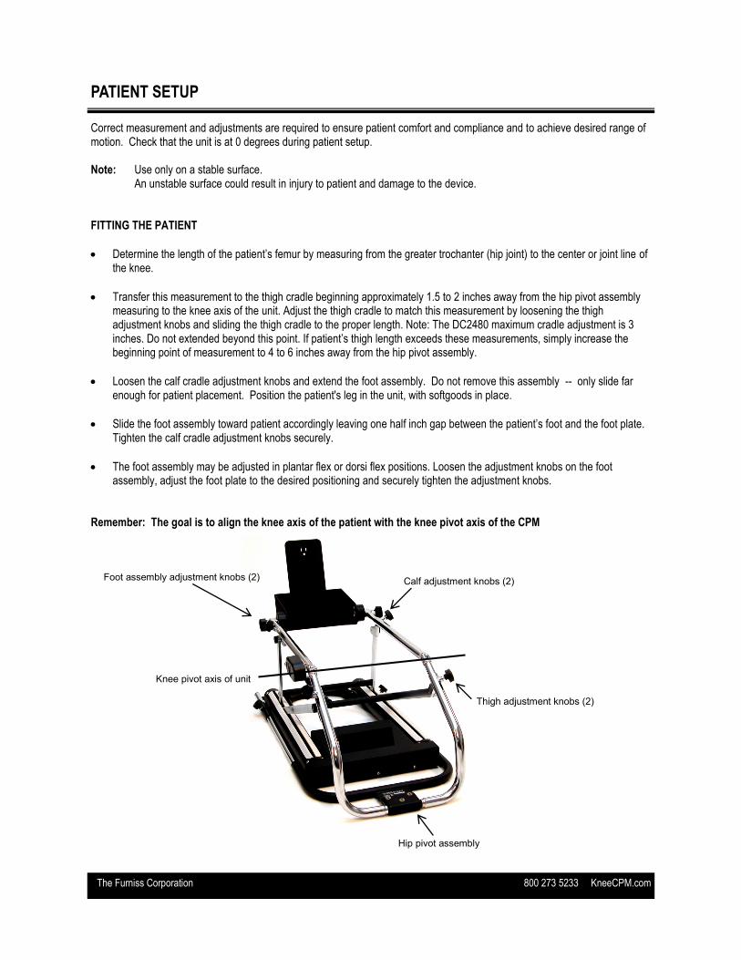
Remember: The goal is to align the knee axis of the patient with the knee pivot axis of the CPM
Hip pivot assembly
Knee pivot axis of unit
Thigh adjustment knobs (2)
Calf adjustment knobs (2) Foot assembly adjustment knobs (2)
The Furniss Corporation 800 273 5233 KneeCPM.com
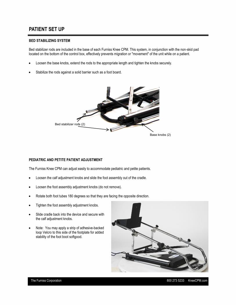
PATIENT SET UP BED STABILIZING SYSTEM Bed stabilizer rods are included in the base of each Furniss Knee CPM. This system, in conjunction with the non-skid pad located on the bottom of the control box, effectively prevents migration or "movement" of the unit while on a patient.
Loosen the base knobs, extend the rods to the appropriate length and tighten the knobs securely.
Stabilize the rods against a solid barrier such as a foot board.
PEDIATRIC AND PETITE PATIENT ADJUSTMENT The Furniss Knee CPM can adjust easily to accommodate pediatric and petite patients.
Loosen the calf adjustment knobs and slide the foot assembly out of the cradle.
Loosen the foot assembly adjustment knobs (do not remove).
Rotate both foot tubes 180 degrees so that they are facing the opposite direction.
Tighten the foot assembly adjustment knobs.
Slide cradle back into the device and secure with the calf adjustment knobs.
Note: You may apply a strip of adhesive-backed loop Velcro to this side of the footplate for added stability of the foot boot softgood.
Bed stabilizer rods (2)
Base knobs (2)

The Furniss Corporation 800 273 5233 KneeCPM.com
OPERATING THE PHOENIX MODEL 1850 AND DC2480 CPM POWER ON AND OFF The ON/OFF switch is located at the base of the black control box. When the unit is powered ON it will beep one (1) time and the hand-held control pendant will illuminate. This indicates that the unit is ready for use. PHOENIX MODEL 1850 KNEE CPM CONTROL PENDANT The Model 1850 control pendant includes of the following functionalities:
Flexion: 0 to 110 degrees
Extension: -5 to 105 degrees
Speed: 1 degree per second at lowest setting, 3 degrees per second at highest setting
Pause: 0 to 30 Seconds*
Patient Compliance Meter
Patient Lock Out Switch DC2480 KNEE CPM CONTROL PENDANT The DC2480 control pendant includes of the following functionalities:
Flexion: 0 to 120 degrees
Extension: -10 to 105 degrees
Speed: 1 degree per second at lowest setting, 3 degrees per second at highest setting
Pause: 0 to 30 Seconds*
Patient Compliance Meter
Patient Lock Out Switch To set Flexion range: Depress the FLX button and the up or down arrow simultaneously. To set Extension range: Depress the EXT button and the up or down arrow simultaneously. A 5 degree difference between flexion and extension is required for normal operation. Should the angle settings be too close the incorrect setting on the pendant will flash. To set Speed: Depress the Speed button and the up or down arrow simultaneously. When you depress the Speed button, the setting will appear in the ROM window. To set *Pause: Depress the Pause button and the up or down arrow simultaneously. When you depress the Pause button, the setting will appear in the ROM window. Patient Compliance Meter: The patient compliance meter monitors patient usage and tracks in tenths of an hour readings. Example: 25.4 reading = 25 hours and 24 minutes. - Meter is displayed in the Flexion window - The meter is read by depressing the FLX and SPD buttons simultaneously - Clear meter by depressing the EXT, FLX, SPD and Pause buttons simultaneously.
Note: The Start/Stop button must be pressed in order to lock in setting changes.
The Furniss Corporation 800 273 5233 KneeCPM.com
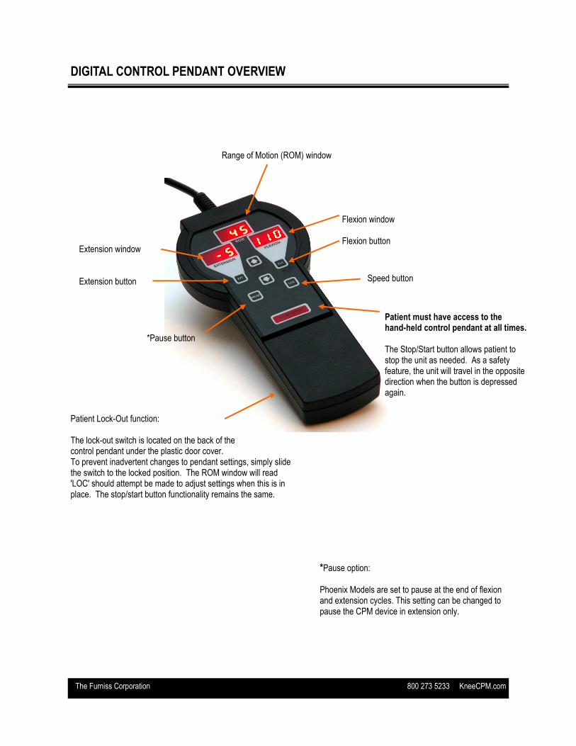
DIGITAL CONTROL PENDANT OVERVIEW
*Pause option: Phoenix Models are set to pause at the end of flexion and extension cycles. This setting can be changed to pause the CPM device in extension only.
Range of Motion (ROM) window
Extension window Extension button
Flexion window Flexion button
*Pause button
Speed button
Patient must have access to the hand-held control pendant at all times. The Stop/Start button allows patient to stop the unit as needed. As a safety feature, the unit will travel in the opposite direction when the button is depressed again.
Patient Lock-Out function: The lock-out switch is located on the back of the control pendant under the plastic door cover. To prevent inadvertent changes to pendant settings, simply slide the switch to the locked position. The ROM window will read 'LOC' should attempt be made to adjust settings when this is in place. The stop/start button functionality remains the same.
The Furniss Corporation 800 273 5233 KneeCPM.com
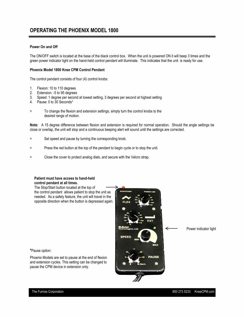
OPERATING THE PHOENIX MODEL 1800 Power On and Off The ON/OFF switch is located at the base of the black control box. When the unit is powered ON it will beep 3 times and the green power indicator light on the hand-held control pendant will illuminate. This indicates that the unit is ready for use. Phoenix Model 1800 Knee CPM Control Pendant The control pendant consists of four (4) control knobs: 1. Flexion: 10 to 110 degrees 2. Extension: -5 to 95 degrees 3. Speed: 1 degree per second at lowest setting, 3 degrees per second at highest setting 4. Pause: 0 to 30 Seconds* > To change the flexion and extension settings, simply turn the control knobs to the desired range of motion. Note: A 15 degree difference between flexion and extension is required for normal operation. Should the angle settings be close or overlap, the unit will stop and a continuous beeping alert will sound until the settings are corrected. > Set speed and pause by turning the corresponding knob. > Press the red button at the top of the pendant to begin cycle or to stop the unit. > Close the cover to protect analog dials, and secure with the Velcro strap.
Power indicator light
Patient must have access to hand-held control pendant at all times. The Stop/Start button located at the top of the control pendant allows patient to stop the unit as needed. As a safety feature, the unit will travel in the opposite direction when the button is depressed again.
*Pause option:
Phoenix Models are set to pause at the end of flexion and extension cycles. This setting can be changed to pause the CPM device in extension only.

The Furniss Corporation 800 273 5233 KneeCPM.com
MAINTENANCE Recommended Tools
After each use, clean the unit using a soft cloth dampened with water and a mild antibacterial detergent or sani-cloth disinfecting wipe. Pendant Care The pendant is a vital component of the entire CPM device. Furniss Corp builds two types of pendants for the equipment manufactured. The Phoenix Model 1850 and the DC2480 feature a digital pendant and the Phoenix Model 1800 maintains an analog hand control. Digital Pendant (Model 1850/ Model DC2480): Inspect the overlay for any damage. Confirm operation of the pendant cable. Replace as needed. Analog Pendant (Model 1800): Fasten the Start/Stop switch tightly. Secure the control knobs. Verify operation of the pendant cable. Replace as needed. Tighten All Fasteners Ensure all of the knobs, screws, bolts and other fasteners are secure to maintain operational use. It is recommend that these parts are checked each time a unit is placed on a patient to guarantee peak performance. A suggested Locktite product assists to secure the fasteners. Contact the Technical Service Department for recommendations on which type of Locktite to use on certain fasteners. Toll free 800.273.5233.
Small Phillips Screwdriver 1/8 T Handle Allen Wrench Basic Volt Meter
Small Flat Head Screwdriver 3/32 T Handle Allen Wrench Light Building Grease (front end cap roller bearing)
Phillips Screwdriver 9/64 T Handle Allen Wrench Red Loctite (shoulder bolt/acorn nut/calf + thigh tube bolt)
Large Flat Head Screwdriver 5/32 T Handle Allen Wrench Blue Loctite (strut support bolt/set screws on pulleys + couplings)
Small Needle Nose Pliers 3/4 Wrench (pendant cable/knee pot strain relief)
Purple Loctite (thigh block screws/small allen bolt in foot plate)
Standard Pliers 5/64 Hex Key Allen Wrench (set screws)
Cleaning Supplies for adhesive removal / Goo Gone
Vise Grips 7/16 Nut Driver (foot plate)
100% Clear Silicone Adhesive (Order # adhesive)
Small Rubber Hammer Small Crescent Wrench Velcro Cleaner
The Furniss Corporation 800 273 5233 KneeCPM.com
MAINTENANCE
Track Seal Maintenance Track seals serve to protect each ball screw component. If the track seal is ripped or torn, it must be replaced. A damaged track seal allows large particles to enter the ball screw assembly, thus causing the unit to not operate properly. Remove the dry adhesive from the unit before continuing. Replace the track seal following instructions provided with the part. The best adhesive to use is a product that is 100% silicone, which is available for purchase from Furniss Corp. Do Not Use any kind of a super glue or cement paste. Ball Screw Assembly The ball screw assembly assists the leg carriage to progress between different degrees of flexion and extension. This part of the unit is in constant motion and it is very important that the entire assembly is properly maintained.
Ensure the screw is properly lubricated. The ball screw assembly should have a wet appearance. Excessive lubricant will affect the performance. Furniss Corp recommends white building grease for optimum function. A lithium based lubricant is also acceptable. We do not recommend any type of spray lubricant or grease – including WD40, or a spray silicone product. Do not use heavy grease for lubrication.
Keep the ball screw assembly free of debris. Refer to previous track seal section for additional prevention details.
Use patient softgood set item #1828-1 for these units. Furniss Corp softgoods have been specifically designed to properly fit the CPM unit. By using this set it will eliminate any opportunity for large pieces of debris to enter the ball screw assembly. Please call our Client Services Department at 800.273.5233 to order the softgood pads (Item# 1828-1).
Carbon Removal from the Motor Overtime carbon dust will be generated by the motor. The build-up of this residue can affect the efficiency of the motor. With continuous use, the carbon should be removed from the motor every three months to extend the life of the part. Follow the steps below to clean carbon from the motor.
Remove the motor and gearbox from the CPM unit.
Loosen the two screws at the top of the motor.
Blow compressed air through that opening which will remove the dust. Summary These are just a few maintenance suggestions to assist in the performance and longevity of the CPM units. Contact the Technical Service Department before purchasing any replacement parts for your CPM unit. Furniss Corp is the only supplier for original equipment parts. Should the CPM unit require service, please do not hesitate to contact us. As always, we are here to answer any questions and help with any issues regarding the CPM units.
The Furniss Corporation 800 273 5233 KneeCPM.com
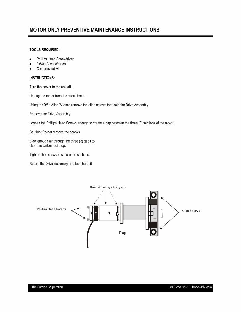
MOTOR ONLY PREVENTIVE MAINTENANCE INSTRUCTIONS
TOOLS REQUIRED:
Phillips Head Screwdriver
9/64th Allen Wrench
Compressed Air INSTRUCTIONS: Turn the power to the unit off. Unplug the motor from the circuit board. Using the 9/64 Allen Wrench remove the allen screws that hold the Drive Assembly. Remove the Drive Assembly. Loosen the Phillips Head Screws enough to create a gap between the three (3) sections of the motor. Caution: Do not remove the screws. Blow enough air through the three (3) gaps to clear the carbon build up. Tighten the screws to secure the sections. Return the Drive Assembly and test the unit.
A S im ple P reventative M aintenance
P rocedure to C lear the C arbon from the
P hoenix M otor
Plug
Ph illips H ead Screw s
Blo w a ir thro ug h the g a p s
Tools R equired:
Instructions:
-9/64 A llen W rench
-Phillips H ead S crew driver
-C om pressed A ir
1 . Turn the pow er o ff to the unit.
2 . U nplug the m otor from the circu it board
3. U sing the 9 /64 A llen W rench rem ove the a llen screw s that ho ld the D rive
Assem bly.
4 . R em ove the D rive Assem bly.
5 . Loosen the PhillipsH ead Screw s enough to create a gap betw een the 3
sections o f the m otor.
6 . B low enough a ir to clear the carbon build up.
7 . Tighten the screw s enough to secure the sections.
8 . R eturn the D rive Assem bly and test th e unit.
B e carefu l not to rem ove the screw s
th rough the gaps (3)
Allen S crew s1 2 3
Toll F ree 800.273.5233 614.871.1470 Fax: 614.871.1470
To:______________________________________________
C om pany:________________________________________
Fax:_____________________________________________
1 /9/03 LM
Plug
The Furniss Corporation 800 273 5233 KneeCPM.com
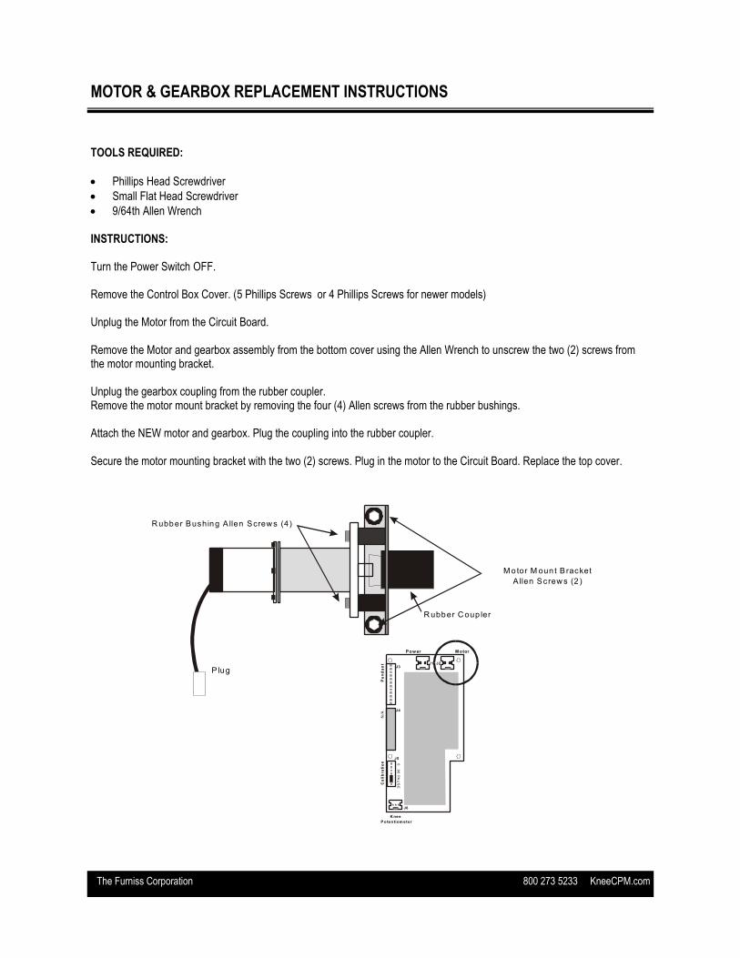
MOTOR & GEARBOX REPLACEMENT INSTRUCTIONS
TOOLS REQUIRED:
Phillips Head Screwdriver
Small Flat Head Screwdriver
9/64th Allen Wrench INSTRUCTIONS: Turn the Power Switch OFF. Remove the Control Box Cover. (5 Phillips Screws or 4 Phillips Screws for newer models) Unplug the Motor from the Circuit Board. Remove the Motor and gearbox assembly from the bottom cover using the Allen Wrench to unscrew the two (2) screws from the motor mounting bracket. Unplug the gearbox coupling from the rubber coupler. Remove the motor mount bracket by removing the four (4) Allen screws from the rubber bushings. Attach the NEW motor and gearbox. Plug the coupling into the rubber coupler. Secure the motor mounting bracket with the two (2) screws. Plug in the motor to the Circuit Board. Replace the top cover.
Replacing the M otor & G earbox
Tools requ ired :
Phillips H ead Screw driver, Sm all Flat H ead
Screw driver, 9/64th A llen W rench
1. Turn the P ow er S w itch O FF.
2. R em ove the C ontrol Box Cover. (5 Phillips
Screw s)
3. U nplug the M otor from the C ircuit Board.
4. R em ove the M otor and gearbox assem bly using the A llen
W rench to unscrew the tw o(2) screw s from the m otor
m ounting bracket.
5 . U nplug the gearbox coupling from the rubber coupler.
6 . R em ove the m otor m ount bracket by rem oving the (4)
A llen screw s from the rubber bushings ..
7 . A ttach the N E W m otor and gearbox.
8. Plug the coupling into the rubber coupler.
9 . Secure the m otor m ounting bracket w ith the tw o (2)
screw s.
10. Plug in the m otor to the C ircuit Board.
11. R eplace the top cover.
R ubber C oup ler
M o tor M oun t B racket
A llen Screw s (2 )
R ubber Bushing A llen Screw s (4)
P lugJ1 J2
J3
J4
J6
Pow er M otor
Pe
nd
an
tN
/AC
ali
bra
tio
n
K nee
P o ten tiom eter
J5
0 9
0 P
AU
SE
Toll F ree 800.273.5233 614.871.1470 Fax: 614.871.1470
To:______________________________________________
C om pany:________________________________________
Fax:_____________________________________________
1903 LM
The Furniss Corporation 800 273 5233 KneeCPM.com
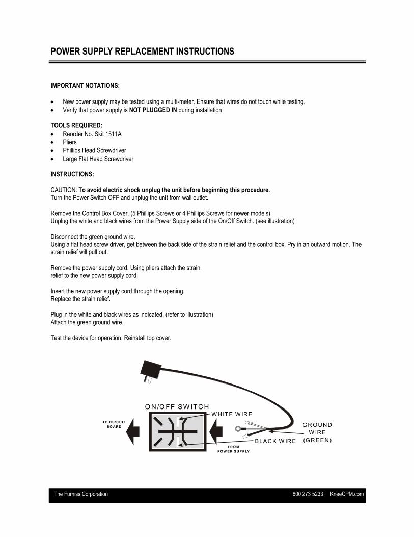
POWER SUPPLY REPLACEMENT INSTRUCTIONS
IMPORTANT NOTATIONS:
New power supply may be tested using a multi-meter. Ensure that wires do not touch while testing.
Verify that power supply is NOT PLUGGED IN during installation TOOLS REQUIRED:
Reorder No. Skit 1511A
Pliers
Phillips Head Screwdriver
Large Flat Head Screwdriver INSTRUCTIONS: CAUTION: To avoid electric shock unplug the unit before beginning this procedure. Turn the Power Switch OFF and unplug the unit from wall outlet. Remove the Control Box Cover. (5 Phillips Screws or 4 Phillips Screws for newer models) Unplug the white and black wires from the Power Supply side of the On/Off Switch. (see illustration) Disconnect the green ground wire. Using a flat head screw driver, get between the back side of the strain relief and the control box. Pry in an outward motion. The strain relief will pull out. Remove the power supply cord. Using pliers attach the strain relief to the new power supply cord. Insert the new power supply cord through the opening. Replace the strain relief. Plug in the white and black wires as indicated. (refer to illustration) Attach the green ground wire. Test the device for operation. Reinstall top cover.
Tools R eq uired:
Pliers, Phillips H ead Screw driver
C aution: To avoid electric shock unplug the unit before beginning this
procedure.
1. Turn the P ow er S w itch O FF and unplug the unit from w all outlet.
2 . R em ove the C ontrol Box Cover. (5 Phillips Screw s)
3. U nplug the w hite and black w ires from the PO W ER SU P PLY side
of the of the O N /O FF sw itch. (S ee illustration)
4. D isconnect the green ground w ire
5. U sing the pliers squeeze the sides of the strain-relief. Push the strain-
relief out.
6 . R em ove the pow er supply cord.
7. T hread the new Pow er Supply through the opening.
8. R eplace the strain relief.
9 . Plug in the w hite and black w ires as indicated above. (See illustration)
10. A ttach the green ground w ire.
W HITE W IRE
BLACK W IREFR O M
P OW ER S U P P LY
TO C IR C U IT
B O A R D
Replacing the Pow er Supply
O N /O FF SW ITC H
GR OUND
W IRE
(GREEN)
Toll F ree 800.273.5233 614.871.1470 Fax: 614.871.1470
To:______________________________________________
C om pany:________________________________________
Fax:_____________________________________________
1 /9 /03 LM
The Furniss Corporation 800 273 5233 KneeCPM.com
TRACK SEAL REPLACEMENT INSTRUCTIONS
TOOLS REQUIRED:
Track Seal Kit — Reorder No. Skit 1707A
Adhesive (100% silicon) Reorder Code. ‘Adhesive’
Non-Abrasive Adhesive Remover INSTRUCTIONS: Remove the old track seals. Clean off any adhesive residue from the old track seal. Surfaces must be cleaned thoroughly for the new track seal to adhere properly. Clean with a quality, non-abrasive adhesive remover such as Goo-Gone. Attach the track seals to the edge of the track opening by sliding the open side of the new track seal along the edge of the opening. Lift the top side of the new track seal and apply a bead of adhesive along the full length of the entire strip. Ensure the track seals are pressed tightly against the struts after adhesive application. Run the unit for approximately one (1) hour after application to ensure proper alignment of track seals. View tight positioning of the track seals against the strut. Most adhesives require 24 hours for a complete curing process.
The Furniss Corporation 800 273 5233 KneeCPM.com
Replacing the O N/O FF Sw itch
W riting on
TOP
W HITE W IRES
BLACK W IRES
FR O M
PO W ER S U PPLY
TO C IR C U IT
B O A R D
Tools R eq uired:
Pliers
C aution: To avoid electric shock unplug the unit before beginning this
procedure.
1. Turn the P ow er S w itch O FF and unplug unit from w all outlet.
2 . R em ove the C ontrol Box Cover. (5 Phillips Screw s)
3. U nplug the the 2 w hite and 2 black w ires from the back of the
O N /O FF sw itch.
4. U se the pliers to squeeze the fastening clips and push the sw itch out.
5 . Press the new O N /O FF sw itch into position.
6. Plug in the W H ITE and BL A C K w ires as indicated above.(See
illustration)
7. R eplace the cover.
FASTENING
CLIPS
Toll F ree 800.273.5233 614.871.1470 Fax: 614.871.1470
To:______________________________________________
C om pany:________________________________________
Fax:_____________________________________________
1 /9 /03 LM
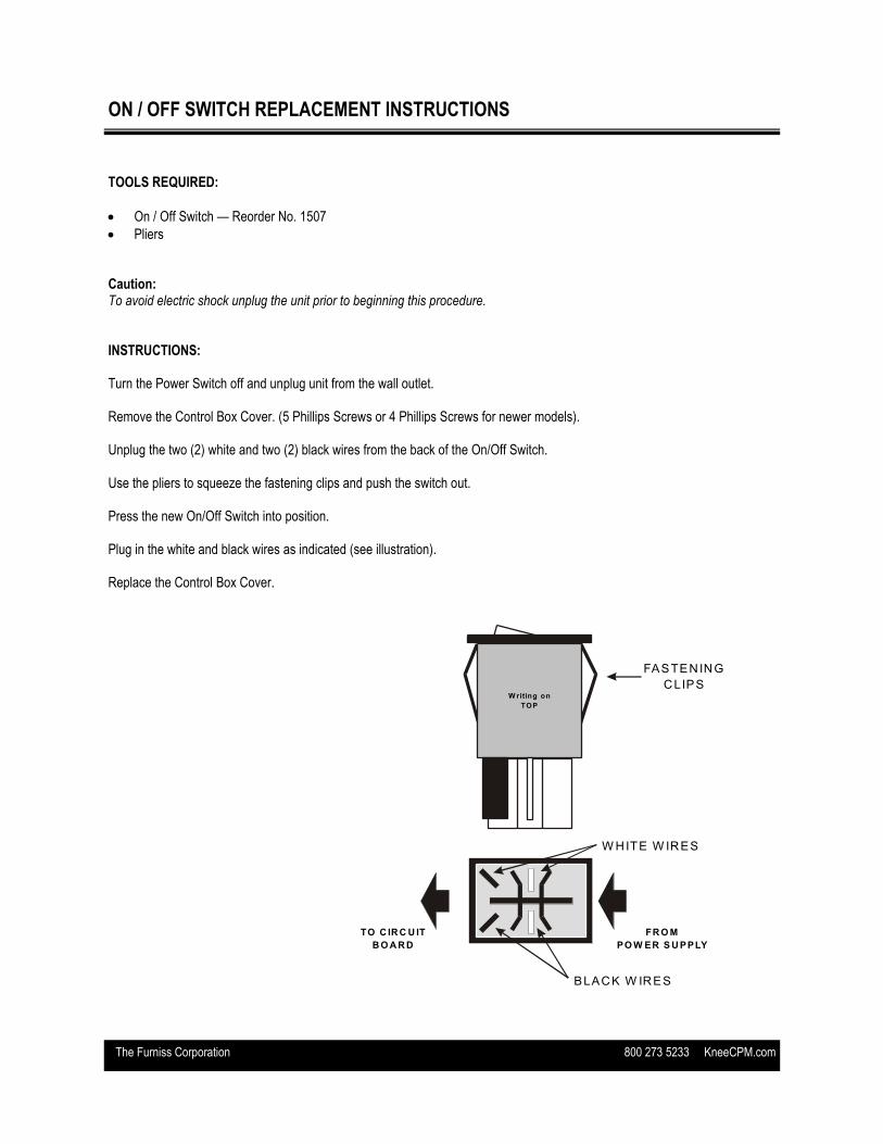
ON / OFF SWITCH REPLACEMENT INSTRUCTIONS
TOOLS REQUIRED:
On / Off Switch — Reorder No. 1507
Pliers Caution: To avoid electric shock unplug the unit prior to beginning this procedure. INSTRUCTIONS: Turn the Power Switch off and unplug unit from the wall outlet. Remove the Control Box Cover. (5 Phillips Screws or 4 Phillips Screws for newer models). Unplug the two (2) white and two (2) black wires from the back of the On/Off Switch. Use the pliers to squeeze the fastening clips and push the switch out. Press the new On/Off Switch into position. Plug in the white and black wires as indicated (see illustration). Replace the Control Box Cover.
The Furniss Corporation 800 273 5233 KneeCPM.com
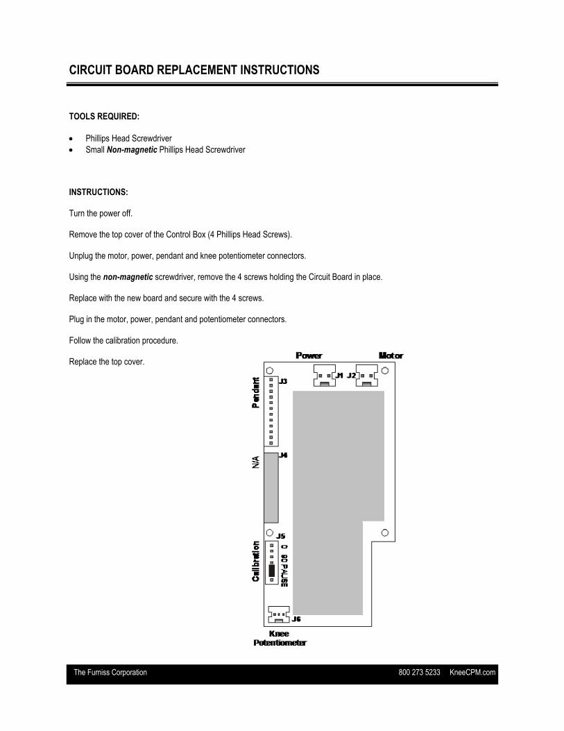
CIRCUIT BOARD REPLACEMENT INSTRUCTIONS
TOOLS REQUIRED:
Phillips Head Screwdriver
Small Non-magnetic Phillips Head Screwdriver INSTRUCTIONS: Turn the power off. Remove the top cover of the Control Box (4 Phillips Head Screws). Unplug the motor, power, pendant and knee potentiometer connectors. Using the non-magnetic screwdriver, remove the 4 screws holding the Circuit Board in place. Replace with the new board and secure with the 4 screws. Plug in the motor, power, pendant and potentiometer connectors. Follow the calibration procedure. Replace the top cover.
The Furniss Corporation 800 273 5233 KneeCPM.com
CALIBRATION PROCEDURE MODEL 1800
TOOLS REQUIRED: Straight Edge, Protractor, 3/32 Allen Wrench, Phillips Screwdriver, 2 Position Jumper, Voltmeter INSTRUCTIONS: Turn the machine off. Remove knee potentiometer cover. Remove top cover of the unit. Remove 2 position jumper from J5. Place the 2 position jumper on the zero (0) position pins 1 and 2 (Counting from the Foot Plate down) Turn the machine on. Listen for 2 audible beeps. Using the Start/Stop button on the Pendant move the unit into the zero position. Use a straight edge to determine the zero. Stop the unit in that position. Verify the Knee Pot Voltage is 2.0 volts DC. To test this use a volt meter and touch the red lead to the red wire and the black lead to the black wire on the knee pot. If reading is not at 2.0 volts DC then you must loosen the knee pot clamps and turn the knee pot either clockwise or counter clockwise to achieve 2.0 volts (Warning while doing this procedure watch the tension on the 3 wires coming from the knee pot cable) Then tighten clamps to lock the knee pot down when 2.0 volts is achieved Remove the 2 position jumper from zero (0) position Pins 1 and 2. Listen for audible beeps. Place 2 position jumper on the 90 degree position (90) Pins 3 and 4. Using the Start/Stop button on the Pendant move the unit into the 90 degree position (90) using a protractor or similar device. Stop the unit in that position. Remove the 2 position jumper from the 90 degree position pins 3 and 4. Listen for audible beeps. Verify the hand control settings are 0-Pause, Max- Speed, -5 extension and 110 flexion. Press the start/stop button on the hand control and allow the unit to travel through the full range of motion. If the unit travels through the full range of motion without binding then unit has been successfully calibrated. Reinstall 2 position jumper on its original settings pins 5 and 6 or pins 6 and 7 2 position jumper on pins 5 and 6 (Pause in Extension only) 2 position jumper on pins 6 and 7 (Pause in Extension and Flexion)
The Furniss Corporation 800 273 5233 KneeCPM.com
CALIBRATION PROCEDURE MODEL 1850
TOOLS REQUIRED: Straight Edge, Protractor, 3/32 Allen Wrench, Phillips Screwdriver INSTRUCTIONS: Turn power off Remove knee potentiometer cover Remove top cover from the unit Move SW1 slide switch located at the bottom left of the board from run to calibrate Using the up and down arrows move the unit to the zero position Use a straight edge to determine zero Look for these values on the hand control Ext. window (Letter F with a red dot) ROM Window (2) Flexion Window (490) reading this as 2490 (2490 represents the zero setting) If these values are not present then the unit is out of calibration If the above values do not appear on the hand control then it is necessary to move the knee pot to gain these values. To move the knee pot, loosen the clamps on the knee pot and turn the knee pot clockwise or counterclockwise to achieve the above readings. Once these values have been achieved then tighten the knee pot clamps. To lock in the zero (0) position, depress the ext. button 1 time and listen for an audible beep. By depressing the UP arrow button you can move the unit into the 90 degree (90) position, using a protractor or similar device, stopping at this position Once in the 90 degree position (90) and if you are in the approximate range a red dot will be visible in the flexion window. If the red dot is visible then depress the flexion button 1 time and listen for an audible beep. Switch unit from calibration mode to run mode Set hand control at -5 extension, 110 Flexion, 0 pause, and 10 speed Depress start/stop switch on the hand control and allow unit to travel through full range of motion. If the unit travels the full range of motion without binding then the unit has been calibrated successfully.
The Furniss Corporation 800 273 5233 KneeCPM.com
CALIBRATION PROCEDURE MODEL DC2480
TOOLS REQUIRED: Straight Edge, Protractor, 3/32 Allen Wrench, Phillips Screwdriver INSTRUCTIONS: Turn power off Remove knee potentiometer cover Remove top cover from the unit Move SW1 slide switch located at the bottom left of the board from run to calibrate Using the up and down arrows move the unit to the zero position Use a straight edge to determine zero Look for these values on the hand control Ext. window (Letter F with a red dot) ROM Window (2) Flexion Window (795) reading this as 2795 (2795 represents the zero setting) If these values are not present then the unit is out of calibration If the above values do not appear on the hand control then it is necessary to move the knee pot to gain these values. To move the knee pot, loosen the clamps on the knee pot and turn the knee pot clockwise or counterclockwise to achieve the above readings. Once these values have been achieved then tighten the knee pot clamps. To lock in the zero (0) position, depress the ext. button 1 time and listen for an audible beep. By depressing the UP arrow button you can move the unit into the 90 degree (90) position, using a protractor or similar device, stopping at this position Once in the 90 degree position (90) and if you are in the approximate range a red dot will be visible in the flexion window. If the red dot is visible then depress the flexion button 1 time and listen for an audible beep. Switch unit from calibration mode to run mode Set hand control at –10 extension, 120 Flexion, 0 pause, and 10 speed Depress start/stop switch on the hand control and allow unit to travel through full range of motion. If the unit travels the full range of motion without binding then the unit has been calibrated successfully.
The Furniss Corporation 800 273 5233 KneeCPM.com
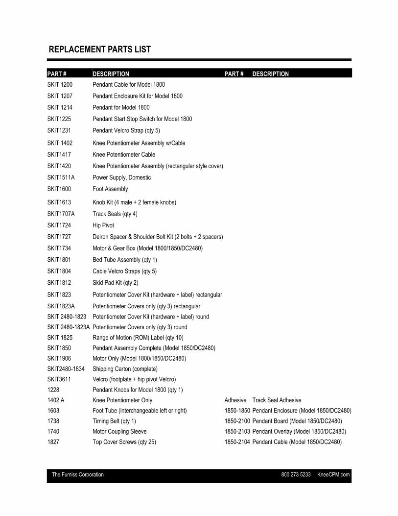
REPLACEMENT PARTS LIST
PART # DESCRIPTION PART # DESCRIPTION
SKIT 1200 Pendant Cable for Model 1800
SKIT 1207 Pendant Enclosure Kit for Model 1800
SKIT 1214 Pendant for Model 1800
SKIT1225 Pendant Start Stop Switch for Model 1800
SKIT1231 Pendant Velcro Strap (qty 5)
SKIT 1402 Knee Potentiometer Assembly w/Cable
SKIT1417 Knee Potentiometer Cable
SKIT1420 Knee Potentiometer Assembly (rectangular style cover)
SKIT1511A Power Supply, Domestic
SKIT1600 Foot Assembly
SKIT1613 Knob Kit (4 male + 2 female knobs)
SKIT1707A Track Seals (qty 4)
SKIT1724 Hip Pivot
SKIT1727 Delron Spacer & Shoulder Bolt Kit (2 bolts + 2 spacers)
SKIT1734 Motor & Gear Box (Model 1800/1850/DC2480)
SKIT1801 Bed Tube Assembly (qty 1)
SKIT1804 Cable Velcro Straps (qty 5)
SKIT1812 Skid Pad Kit (qty 2)
SKIT1823 Potentiometer Cover Kit (hardware + label) rectangular
SKIT1823A Potentiometer Covers only (qty 3) rectangular
SKIT 2480-1823 Potentiometer Cover Kit (hardware + label) round
SKIT 2480-1823A Potentiometer Covers only (qty 3) round
SKIT 1825 Range of Motion (ROM) Label (qty 10)
SKIT1850 Pendant Assembly Complete (Model 1850/DC2480)
SKIT1906 Motor Only (Model 1800/1850/DC2480)
SKIT2480-1834 Shipping Carton (complete)
SKIT3611 Velcro (footplate + hip pivot Velcro)
1228 Pendant Knobs for Model 1800 (qty 1)
1402 A Knee Potentiometer Only Adhesive Track Seal Adhesive
1603 Foot Tube (interchangeable left or right) 1850-1850 Pendant Enclosure (Model 1850/DC2480)
1738 Timing Belt (qty 1) 1850-2100 Pendant Board (Model 1850/DC2480)
1740 Motor Coupling Sleeve 1850-2103 Pendant Overlay (Model 1850/DC2480)
1827 Top Cover Screws (qty 25) 1850-2104 Pendant Cable (Model 1850/DC2480)
The Furniss Corporation 800 273 5233 KneeCPM.com
WARRANTY
The Furniss Corporation, Ltd. (Furniss Corp) warrants to the original buyer of this Knee CPM machine (the Unit) that the Unit will be free from defects in material or workmanship for a period of Two Years from the date of original purchase from Furniss Corp. This warranty does not cover defects resulting from damage by accident, abuse, misuse, misapplication, or unauthorized repairs or alterations made either by the customer or another party. The Furniss Corporation reserves the right to determine whether the defective product falls into this category. The Furniss Corporation makes no other warranties, expressed or implied (including, without limitation merchantability, fitness for a particular purpose, or against infringement of any patent), except expressly provided herein. If the Unit does not conform to this warranty, The Furniss Corporation will at its option repair or replace the defective Unit.. The remedy of repair or replacement is purchasers’ sole and exclusive remedy and will satisfy all of The Furniss Corporation’s liabilities, whether based on contract, tort, product liability, strict liability, or otherwise. In no event shall its liability in connection with any defective Unit exceed the sales price of such unit. For this limited warranty to apply, buyer must provide Furniss Corp with written notice of a claimed defect within thirty (30) days after the discovery, but no later than the expiration date of the warranty term. Within reasonable time following the receipt of such a notice, The Furniss Corporation will advise the purchaser of the disposition of the Unit. Unless expressly authorized in writing, the defective Unit must be returned to The Furniss Corporation for coverage. Furniss Corp reserves the right to inspect the Unit to determine the claimed defect is within the coverage of this limited warranty. Returning Your CPM for Repair
Do not discard the original packaging of your Knee CPM. It provides required protection for your unit during shipping and must be used when returning your unit for service. Damages resulting from packaging unit in anything other than the required device container are the responsibility of the owner. Unapproved or badly damaged device containers will be replaced and billed accordingly.
Return Authorization Numbers are required. Contact Customer Support at 800.273.5233 with serial number, contact information and required repair description.
Ship your unit to the Technical Service Department at: THE FURNISS CORPORATION, LTD. ATTN: (RA NUMBER) 3350 URBANCREST INDUSTRIAL DRIVE GROVE CITY, OH 43123