Embed Size (px)
Citation preview
7 A p r i l 2 0 1 6 | V O l 5 3 2 | N A T U r E | 8 5
lETTErdoi:10.1038/nature17189
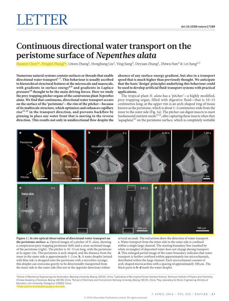
Continuous directional water transport on the peristome surface of Nepenthes alataHuawei Chen1*, pengfei Zhang1*, liwen Zhang1, Hongliang liu2, Ying Jiang3, Deyuan Zhang1, Zhiwu Han4 & lei Jiang2,3
Numerous natural systems contain surfaces or threads that enable directional water transport1–7. This behaviour is usually ascribed to hierarchical structural features at the microscale and nanoscale, with gradients in surface energy8,9 and gradients in Laplace pressure10 thought to be the main driving forces. Here we study the prey-trapping pitcher organs of the carnivorous plant Nepenthes alata. We find that continuous, directional water transport occurs on the surface of the ‘peristome’—the rim of the pitcher—because of its multiscale structure, which optimizes and enhances capillary rise11,12 in the transport direction, and prevents backflow by pinning in place any water front that is moving in the reverse direction. This results not only in unidirectional flow despite the
absence of any surface-energy gradient, but also in a transport speed that is much higher than previously thought. We anticipate that the basic ‘design’ principles underlying this behaviour could be used to develop artificial fluid-transport systems with practical applications.
The tropical plant N. alata has a ‘pitcher’—a highly modified, prey-trapping organ, filled with digestive fluid—that is 10–15 centimetres long; at the upper rim is an arch-shaped ring of tissue known as the peristome, which is about 1–2 centimetres wide from the inner to the outer side (Fig. 1a). The pitcher can digest insects to meet fundamental nutrient needs13,14, after capturing these insects when they ‘aquaplane’15 on the peristome surface, which is completely wettable
1School of Mechanical Engineering and Automation, Beihang University, Beijing 100191, China. 2Laboratory of Bio-inspired Smart Interface Science, Technical Institute of Physics and Chemistry, Chinese Academy of Sciences, Beijing 100190, China. 3School of Chemistry and Environment, Beihang University, Beijing 100191, China. 4Key Laboratory for Bionic Engineering, Ministry of Education, Jilin University, Changchun 130022, China.*These authors contributed equally to this work.
a
Peristome
Pitcher
Inner side
Outer side
5 cm
b 0 s
1 cm
0.40 s 1.56 s
Microlitre syringe
1 cm
c 0 s 0.43 s 0.83 s
Inner side
Outer side
500 μm
d
100 μm
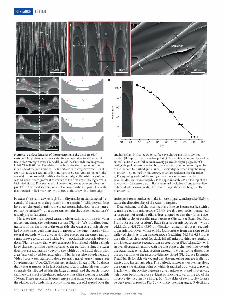
Figure 1 | In situ optical observation of directional water transport on the peristome surface. a, Optical images of a pitcher of N. alata, showing a conspicuous prey-trapping peristome (left) and a cross-sectional image of the peristome (right). The pitcher is 10–15 cm long, with the peristome at its upper rim. This peristome is arch-shaped, and the distance from the inner to the outer side is approximately 1–2 cm. b, A water droplet (mixed with blue ink) is dropped onto the peristome with a microlitre syringe; this droplet can overcome gravity to be directionally transported from the inner side to the outer side (but not in the opposite direction) within
several seconds. The red arrows show the direction of water transport. c, Water transport from the inner side to the outer side is confined within a single large channel. The starting boundary line (marked by white rectangles) of deposited water does not change during transport. d, This enlarged partial image of the water boundary indicates that water transport is further confined within approximately ten microchannels, distributed within the large channel. Each microchannel consists of arch-shaped microcavities with a spacing of approximately 100 μm. The black parts in b–d mark the water droplet.
© 2016 Macmillan Publishers Limited. All rights reserved
8 6 | N A T U r E | V O l 5 3 2 | 7 A p r i l 2 0 1 6
LetterreSeArCH
by water from rain, dew or high humidity and by nectar secreted from extrafloral nectaries at the pitcher’s inner margin16,17. Slippery surfaces have been designed to mimic the structure and behaviour of the natural peristome surface18,19, but questions remain about the mechanism(s) underlying its function.
Here, we use high-speed camera observations to monitor water movement along the peristome surface (Fig. 1b). We find directional transport from the inner to the outer side: the water of a droplet depos-ited on the inner peristome margin moves to the outer margin within several seconds, while a water droplet placed on the outer margin cannot move towards the inside. In situ optical microscopic observa-tions (Fig. 1c) show that water transport is confined within a single large channel running perpendicular to the peristome rim; the water does not spread laterally beyond the width of the initial deposition area (marked by white rectangles in Fig. 1c; see also Supplementary Video 1; for water transport along several parallel large channels, see Supplementary Video 2). The higher-resolution image in Fig. 1d shows that water transport is in fact confined to approximately ten micro-channels distributed within the large channel, and that each micro-channel consists of arch-shaped microcavities with a spacing of roughly 100 μm. These structural features ensure that water evaporating from the pitcher and condensing on the inner margin will spread over the
entire peristome surface to make it more slippery, and are also likely to cause the directionality of the water transport.
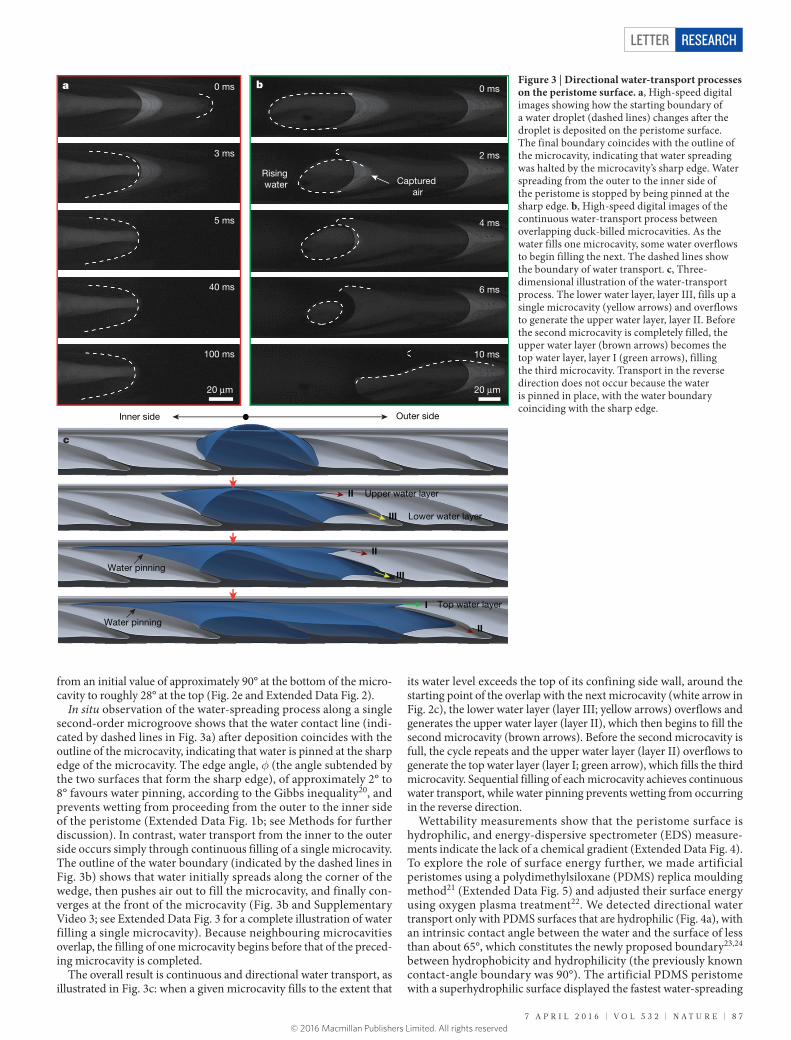
Detailed structural characterization of the peristome surface with a scanning electron microscope (SEM) reveals a two-order hierarchical arrangement of regular radial ridges, aligned so that they form a two- order hierarchy of parallel microgrooves (Fig. 2a; see Extended Data Fig. 1a for a cross-section). Each first-order microgroove—with a width, L1, of 461.72 ± 49.93 μm (Fig. 2a)—contains about ten second- order microgrooves whose width, L2, increases from the ridge to the valley of the first-order microgroove (reaching 50.18 ± 6.18 μm at the valley). Arch-shaped (or duck-billed) microcavities are regularly distributed along the second-order microgrooves (Figs 1d and 2b), with an overall upward slant and with the tops of the arches pointing towards the outer side. A vertical section through the peristome shows that the top sections of the microcavities are closed (Fig. 2c; see Extended Data Fig. 1b for side view), and that the enclosing surface is slightly slanted and has a sharp edge. The periodic microcavities overlap along the ridge (the starting point of which is marked by a white arrow in Fig. 2c), with the overlap between a given microcavity and its overlying neighbour becoming more evident on moving towards the top of the microcavity (red arrows in Fig. 2d). The sides of each cavity form a wedge (green arrows in Fig. 2d), with the opening angle, β, declining
a
500 μm
L1
b
L2
50 μm
A
A
1
2
3
4
c
1
2
3
4
A
A 20 μm
Sharp edge
d
1
2
3
4
1
2
3
4
20 μm
e
100
80
60
40
20
0
10 20 30 40 50 60 70 80 90 100
Hei
ght
(μm
)
(°)
Figure 2 | Surface features of the peristome in the pitchers of N. alata. a, The peristome surface exhibits a unique structural feature of two-order microgrooves. The width, L1, of the first-order microgroove is 461.72 ± 49.93 μm. The white arrow indicates the direction of the inner side of the peristome. b, Each first-order microgroove consists of approximately ten second-order microgrooves, each containing periodic duck-billed microcavities with arch-shaped edges. The width, L2, of the second-order microgroove at the valley of the first-order microgroove is 50.18 ± 6.18 μm. The numbers 1–4 correspond to the same numbers in panel d. c, A vertical section taken at the A–A position in panel b reveals that the duck-billed microcavity is closed at the top, with a sharp edge,
and has a slightly slanted outer surface. Neighbouring microcavities overlap (the approximate starting point of the overlap is marked by a white arrow). d, Each duck-billed microcavity possesses sloping (‘gradient’) wedge-shaped corners, marked by green arrows; gradient opening angles, β, are marked by dashed green lines. The overlap between neighbouring microcavities, marked by red arrows, becomes evident along the ridge. e, The opening angles of the wedge-shaped corners show that the gradient declines from roughly 90° to approximately 28° on the top of the microcavity (the error bars indicate standard deviations from at least five independent measurements). The insert image shows the height of the microcavity.
© 2016 Macmillan Publishers Limited. All rights reserved
7 A p r i l 2 0 1 6 | V O l 5 3 2 | N A T U r E | 8 7
Letter reSeArCH
from an initial value of approximately 90° at the bottom of the micro-cavity to roughly 28° at the top (Fig. 2e and Extended Data Fig. 2).
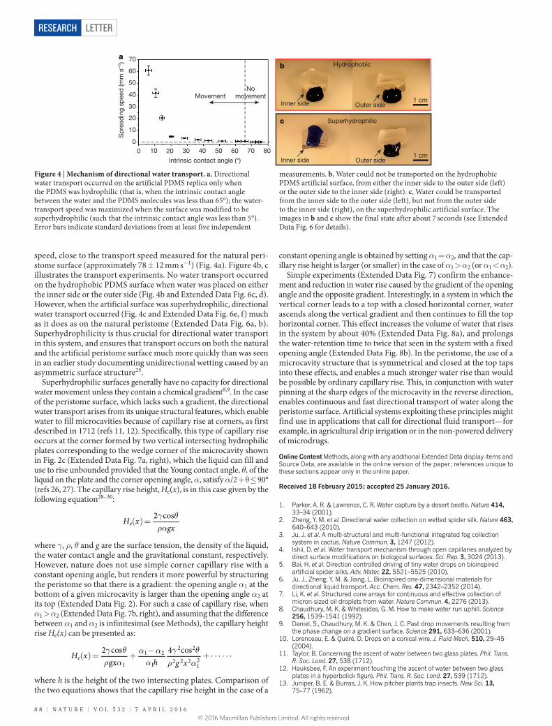
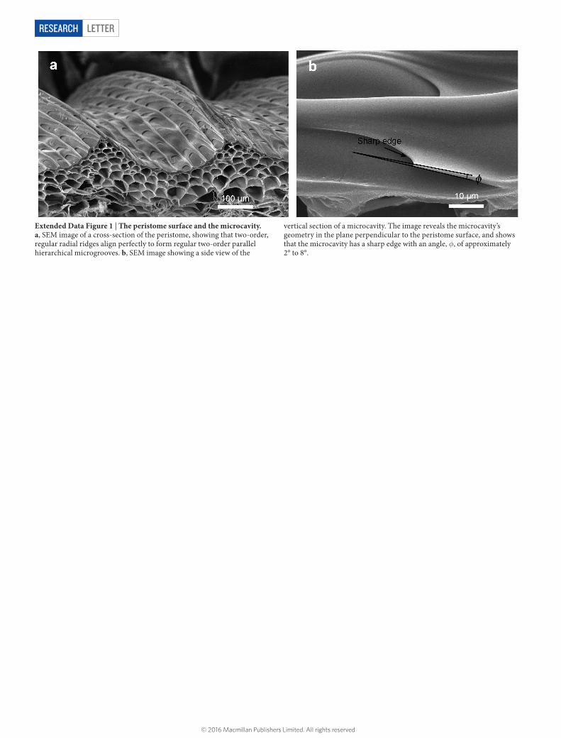
In situ observation of the water-spreading process along a single second-order microgroove shows that the water contact line (indi-cated by dashed lines in Fig. 3a) after deposition coincides with the outline of the microcavity, indicating that water is pinned at the sharp edge of the microcavity. The edge angle, φ (the angle subtended by the two surfaces that form the sharp edge), of approximately 2° to 8° favours water pinning, according to the Gibbs inequality20, and prevents wetting from proceeding from the outer to the inner side of the peristome (Extended Data Fig. 1b; see Methods for further discussion). In contrast, water transport from the inner to the outer side occurs simply through continuous filling of a single microcavity. The outline of the water boundary (indicated by the dashed lines in Fig. 3b) shows that water initially spreads along the corner of the wedge, then pushes air out to fill the microcavity, and finally con-verges at the front of the microcavity (Fig. 3b and Supplementary Video 3; see Extended Data Fig. 3 for a complete illustration of water filling a single microcavity). Because neighbouring microcavities overlap, the filling of one microcavity begins before that of the preced-ing microcavity is completed.
The overall result is continuous and directional water transport, as illustrated in Fig. 3c: when a given microcavity fills to the extent that
its water level exceeds the top of its confining side wall, around the starting point of the overlap with the next microcavity (white arrow in Fig. 2c), the lower water layer (layer III; yellow arrows) overflows and generates the upper water layer (layer II), which then begins to fill the second microcavity (brown arrows). Before the second microcavity is full, the cycle repeats and the upper water layer (layer II) overflows to generate the top water layer (layer I; green arrow), which fills the third microcavity. Sequential filling of each microcavity achieves continuous water transport, while water pinning prevents wetting from occurring in the reverse direction.
Wettability measurements show that the peristome surface is hydrophilic, and energy-dispersive spectrometer (EDS) measure-ments indicate the lack of a chemical gradient (Extended Data Fig. 4). To explore the role of surface energy further, we made artificial peristomes using a polydimethylsiloxane (PDMS) replica moulding method21 (Extended Data Fig. 5) and adjusted their surface energy using oxygen plasma treatment22. We detected directional water transport only with PDMS surfaces that are hydrophilic (Fig. 4a), with an intrinsic contact angle between the water and the surface of less than about 65°, which constitutes the newly proposed boundary23,24 between hydrophobicity and hydrophilicity (the previously known contact-angle boundary was 90°). The artificial PDMS peristome with a superhydrophilic surface displayed the fastest water-spreading
a
20 μm
0 ms
3 ms
5 ms
40 ms
100 ms
b 0 ms
2 ms
4 ms
6 ms
10 ms
Captured air
Rising water
20 μm
c
Water pinning
Water pinning
Upper water layer
Lower water layer
Top water layerI
II
II
II
III
III
Inner side Outer side
Figure 3 | Directional water-transport processes on the peristome surface. a, High-speed digital images showing how the starting boundary of a water droplet (dashed lines) changes after the droplet is deposited on the peristome surface. The final boundary coincides with the outline of the microcavity, indicating that water spreading was halted by the microcavity’s sharp edge. Water spreading from the outer to the inner side of the peristome is stopped by being pinned at the sharp edge. b, High-speed digital images of the continuous water-transport process between overlapping duck-billed microcavities. As the water fills one microcavity, some water overflows to begin filling the next. The dashed lines show the boundary of water transport. c, Three-dimensional illustration of the water-transport process. The lower water layer, layer III, fills up a single microcavity (yellow arrows) and overflows to generate the upper water layer, layer II. Before the second microcavity is completely filled, the upper water layer (brown arrows) becomes the top water layer, layer I (green arrows), filling the third microcavity. Transport in the reverse direction does not occur because the water is pinned in place, with the water boundary coinciding with the sharp edge.
© 2016 Macmillan Publishers Limited. All rights reserved
8 8 | N A T U r E | V O l 5 3 2 | 7 A p r i l 2 0 1 6
LetterreSeArCH
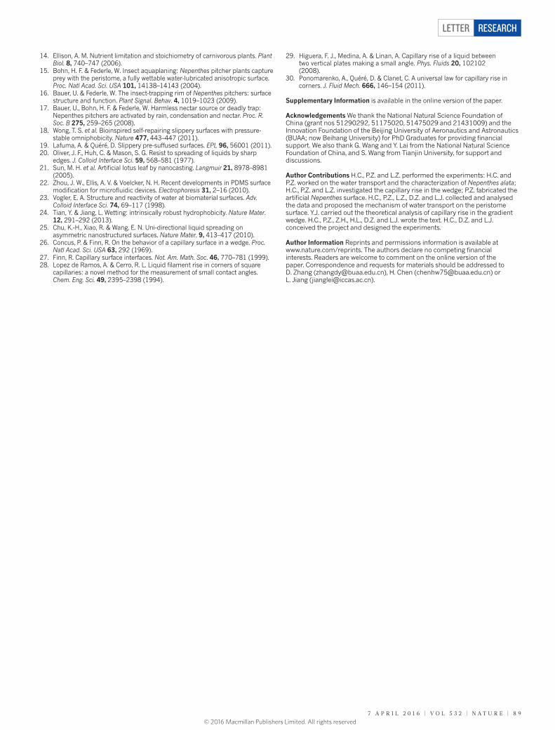
speed, close to the transport speed measured for the natural peri-stome surface (approximately 78 ± 12 mm s−1) (Fig. 4a). Figure 4b, c illustrates the transport experiments. No water transport occurred on the hydrophobic PDMS surface when water was placed on either the inner side or the outer side (Fig. 4b and Extended Data Fig. 6c, d). However, when the artificial surface was superhydrophilic, directional water transport occurred (Fig. 4c and Extended Data Fig. 6e, f) much as it does as on the natural peristome (Extended Data Fig. 6a, b). Superhydrophilicity is thus crucial for directional water transport in this system, and ensures that transport occurs on both the natural and the artificial peristome surface much more quickly than was seen in an earlier study documenting unidirectional wetting caused by an asymmetric surface structure25.
Superhydrophilic surfaces generally have no capacity for directional water movement unless they contain a chemical gradient8,9. In the case of the peristome surface, which lacks such a gradient, the directional water transport arises from its unique structural features, which enable water to fill microcavities because of capillary rise at corners, as first described in 1712 (refs 11, 12). Specifically, this type of capillary rise occurs at the corner formed by two vertical intersecting hydrophilic plates corresponding to the wedge corner of the microcavity shown in Fig. 2c (Extended Data Fig. 7a, right), which the liquid can fill and use to rise unbounded provided that the Young contact angle, θ, of the liquid on the plate and the corner opening angle, α, satisfy α/2 + θ ≤ 90° (refs 26, 27). The capillary rise height, He(x), is in this case given by the following equation28–30:
γ θρα
( )=H xgx
2 cose
where γ, ρ, θ and g are the surface tension, the density of the liquid, the water contact angle and the gravitational constant, respectively. However, nature does not use simple corner capillary rise with a constant opening angle, but renders it more powerful by structuring the peristome so that there is a gradient: the opening angle α1 at the bottom of a given microcavity is larger than the opening angle α2 at its top (Extended Data Fig. 2). For such a case of capillary rise, when α1 > α2 (Extended Data Fig. 7b, right), and assuming that the difference between α1 and α2 is infinitesimal (see Methods), the capillary height rise He(x) can be presented as:
γ θρ α
α αα
γ θρ α
( )= + − + ⋅ ⋅ ⋅ ⋅ ⋅ ⋅H xh g x
2 cosgx
4 cose
1
1 2
1
2 2
2 2 212
where h is the height of the two intersecting plates. Comparison of the two equations shows that the capillary rise height in the case of a
constant opening angle is obtained by setting α1 = α2, and that the cap-illary rise height is larger (or smaller) in the case of α1 > α2 (or α1 < α2).
Simple experiments (Extended Data Fig. 7) confirm the enhance-ment and reduction in water rise caused by the gradient of the opening angle and the opposite gradient. Interestingly, in a system in which the vertical corner leads to a top with a closed horizontal corner, water ascends along the vertical gradient and then continues to fill the top horizontal corner. This effect increases the volume of water that rises in the system by about 40% (Extended Data Fig. 8a), and prolongs the water-retention time to twice that seen in the system with a fixed opening angle (Extended Data Fig. 8b). In the peristome, the use of a microcavity structure that is symmetrical and closed at the top taps into these effects, and enables a much stronger water rise than would be possible by ordinary capillary rise. This, in conjunction with water pinning at the sharp edges of the microcavity in the reverse direction, enables continuous and fast directional transport of water along the peristome surface. Artificial systems exploiting these principles might find use in applications that call for directional fluid transport—for example, in agricultural drip irrigation or in the non-powered delivery of microdrugs.
Online Content Methods, along with any additional Extended Data display items and Source Data, are available in the online version of the paper; references unique to these sections appear only in the online paper.
received 18 February 2015; accepted 25 January 2016.
1. Parker, A. R. & Lawrence, C. R. Water capture by a desert beetle. Nature 414, 33–34 (2001).
2. Zheng, Y. M. et al. Directional water collection on wetted spider silk. Nature 463, 640–643 (2010).
3. Ju, J. et al. A multi-structural and multi-functional integrated fog collection system in cactus. Nature Commun. 3, 1247 (2012).
4. Ishii, D. et al. Water transport mechanism through open capillaries analyzed by direct surface modifications on biological surfaces. Sci. Rep. 3, 3024 (2013).
5. Bai, H. et al. Direction controlled driving of tiny water drops on bioinspired artificial spider silks. Adv. Mater. 22, 5521–5525 (2010).
6. Ju, J., Zheng, Y. M. & Jiang, L. Bioinspired one-dimensional materials for directional liquid transport. Acc. Chem. Res. 47, 2342–2352 (2014).
7. Li, K. et al. Structured cone arrays for continuous and effective collection of micron-sized oil droplets from water. Nature Commun. 4, 2276 (2013).
8. Chaudhury, M. K. & Whitesides, G. M. How to make water run uphill. Science 256, 1539–1541 (1992).
9. Daniel, S., Chaudhury, M. K. & Chen, J. C. Past drop movements resulting from the phase change on a gradient surface. Science 291, 633–636 (2001).
10. Lorenceau, E. & Quéré, D. Drops on a conical wire. J. Fluid Mech. 510, 29–45 (2004).
11. Taylor, B. Concerning the ascent of water between two glass plates. Phil. Trans. R. Soc. Lond. 27, 538 (1712).
12. Hauksbee, F. An experiment touching the ascent of water between two glass plates in a hyperbolick figure. Phil. Trans. R. Soc. Lond. 27, 539 (1712).
13. Juniper, B. E. & Burras, J. K. How pitcher plants trap insects. New Sci. 13, 75–77 (1962).
a
MovementNo
movement
Intrinsic contact angle (°)
Sp
read
ing
spee
d (m
m s
–1) 70
60
50
40
30
20
10
00 10 20 30 40 50 60 70 80
b Hydrophobic
Inner side Outer side1 cm
c Superhydrophilic
Inner side Outer side1 cm
Figure 4 | Mechanism of directional water transport. a, Directional water transport occurred on the artificial PDMS replica only when the PDMS was hydrophilic (that is, when the intrinsic contact angle between the water and the PDMS molecules was less than 65°); the water-transport speed was maximized when the surface was modified to be superhydrophilic (such that the intrinsic contact angle was less than 5°). Error bars indicate standard deviations from at least five independent
measurements. b, Water could not be transported on the hydrophobic PDMS artificial surface, from either the inner side to the outer side (left) or the outer side to the inner side (right). c, Water could be transported from the inner side to the outer side (left), but not from the outer side to the inner side (right), on the superhydrophilic artificial surface. The images in b and c show the final state after about 7 seconds (see Extended Data Fig. 6 for details).
© 2016 Macmillan Publishers Limited. All rights reserved
7 A p r i l 2 0 1 6 | V O l 5 3 2 | N A T U r E | 8 9
Letter reSeArCH
14. Ellison, A. M. Nutrient limitation and stoichiometry of carnivorous plants. Plant Biol. 8, 740–747 (2006).
15. Bohn, H. F. & Federle, W. Insect aquaplaning: Nepenthes pitcher plants capture prey with the peristome, a fully wettable water-lubricated anisotropic surface. Proc. Natl Acad. Sci. USA 101, 14138–14143 (2004).
16. Bauer, U. & Federle, W. The insect-trapping rim of Nepenthes pitchers: surface structure and function. Plant Signal. Behav. 4, 1019–1023 (2009).
17. Bauer, U., Bohn, H. F. & Federle, W. Harmless nectar source or deadly trap: Nepenthes pitchers are activated by rain, condensation and nectar. Proc. R. Soc. B 275, 259–265 (2008).
18. Wong, T. S. et al. Bioinspired self-repairing slippery surfaces with pressure-stable omniphobicity. Nature 477, 443–447 (2011).
19. Lafuma, A. & Quéré, D. Slippery pre-suffused surfaces. EPL 96, 56001 (2011).20. Oliver, J. F., Huh, C. & Mason, S. G. Resist to spreading of liquids by sharp
edges. J. Colloid Interface Sci. 59, 568–581 (1977).21. Sun, M. H. et al. Artificial lotus leaf by nanocasting. Langmuir 21, 8978–8981
(2005).22. Zhou, J. W., Ellis, A. V. & Voelcker, N. H. Recent developments in PDMS surface
modification for microfluidic devices. Electrophoresis 31, 2–16 (2010).23. Vogler, E. A. Structure and reactivity of water at biomaterial surfaces. Adv.
Colloid Interface Sci. 74, 69–117 (1998).24. Tian, Y. & Jiang, L. Wetting: intrinsically robust hydrophobicity. Nature Mater.
12, 291–292 (2013).25. Chu, K.-H., Xiao, R. & Wang, E. N. Uni-directional liquid spreading on
asymmetric nanostructured surfaces. Nature Mater. 9, 413–417 (2010).26. Concus, P. & Finn, R. On the behavior of a capillary surface in a wedge. Proc.
Natl Acad. Sci. USA 63, 292 (1969).27. Finn, R. Capillary surface interfaces. Not. Am. Math. Soc. 46, 770–781 (1999).28. Lopez de Ramos, A. & Cerro, R. L. Liquid filament rise in corners of square
capillaries: a novel method for the measurement of small contact angles. Chem. Eng. Sci. 49, 2395–2398 (1994).
29. Higuera, F. J., Medina, A. & Linan, A. Capillary rise of a liquid between two vertical plates making a small angle. Phys. Fluids 20, 102102 (2008).
30. Ponomarenko, A., Quéré, D. & Clanet, C. A universal law for capillary rise in corners. J. Fluid Mech. 666, 146–154 (2011).
Supplementary Information is available in the online version of the paper.
Acknowledgements We thank the National Natural Science Foundation of China (grant nos 51290292, 51175020, 51475029 and 21431009) and the Innovation Foundation of the Beijing University of Aeronautics and Astronautics (BUAA; now Beihang University) for PhD Graduates for providing financial support. We also thank G. Wang and Y. Lai from the National Natural Science Foundation of China, and S. Wang from Tianjin University, for support and discussions.
Author Contributions H.C., P.Z. and L.Z. performed the experiments: H.C. and P.Z. worked on the water transport and the characterization of Nepenthes alata; H.C., P.Z. and L.Z. investigated the capillary rise in the wedge; P.Z. fabricated the artificial Nepenthes surface. H.C., P.Z., L.Z., D.Z. and L.J. collected and analysed the data and proposed the mechanism of water transport on the peristome surface. Y.J. carried out the theoretical analysis of capillary rise in the gradient wedge. H.C., P.Z., Z.H., H.L., D.Z. and L.J. wrote the text. H.C., D.Z. and L.J. conceived the project and designed the experiments.
Author Information Reprints and permissions information is available at www.nature.com/reprints. The authors declare no competing financial interests. Readers are welcome to comment on the online version of the paper. Correspondence and requests for materials should be addressed to D. Zhang ([email protected]), H. Chen ([email protected]) or L. Jiang ([email protected]).
© 2016 Macmillan Publishers Limited. All rights reserved
LetterreSeArCH
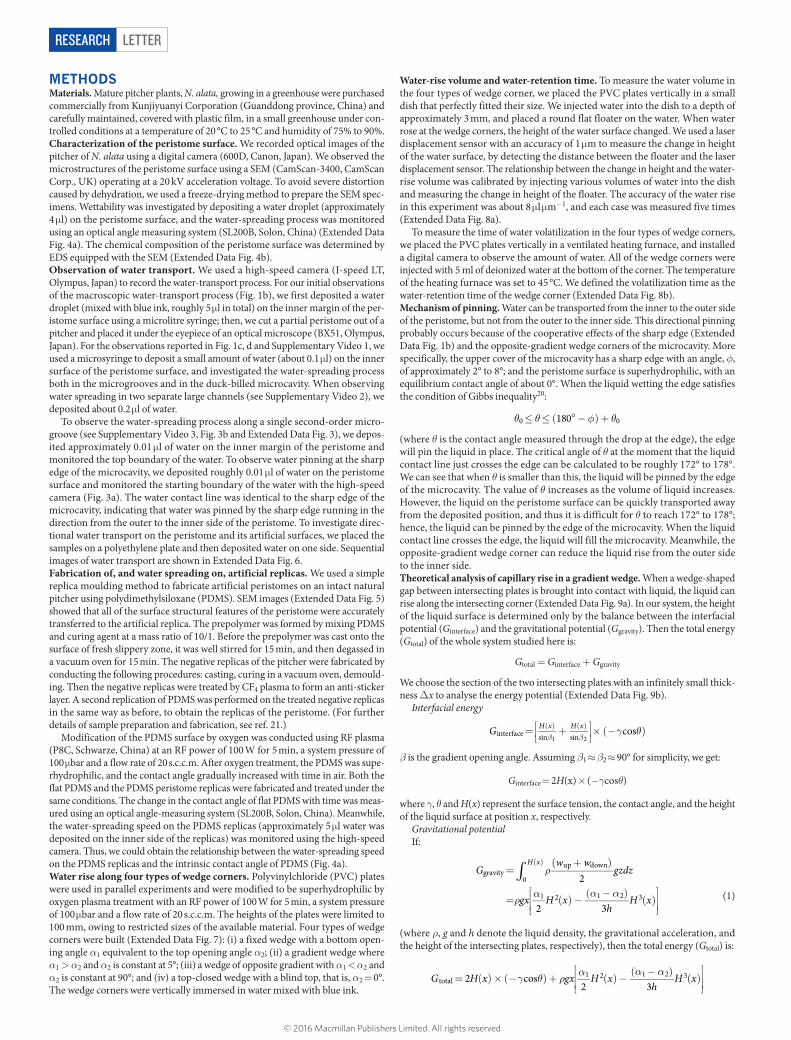
MethOdSMaterials. Mature pitcher plants, N. alata, growing in a greenhouse were purchased commercially from Kunjiyuanyi Corporation (Guanddong province, China) and carefully maintained, covered with plastic film, in a small greenhouse under con-trolled conditions at a temperature of 20 °C to 25 °C and humidity of 75% to 90%.Characterization of the peristome surface. We recorded optical images of the pitcher of N. alata using a digital camera (600D, Canon, Japan). We observed the microstructures of the peristome surface using a SEM (CamScan-3400, CamScan Corp., UK) operating at a 20 kV acceleration voltage. To avoid severe distortion caused by dehydration, we used a freeze-drying method to prepare the SEM spec-imens. Wettability was investigated by depositing a water droplet (approximately 4 μl) on the peristome surface, and the water-spreading process was monitored using an optical angle measuring system (SL200B, Solon, China) (Extended Data Fig. 4a). The chemical composition of the peristome surface was determined by EDS equipped with the SEM (Extended Data Fig. 4b).Observation of water transport. We used a high-speed camera (I-speed LT, Olympus, Japan) to record the water-transport process. For our initial observations of the macroscopic water-transport process (Fig. 1b), we first deposited a water droplet (mixed with blue ink, roughly 5 μl in total) on the inner margin of the per-istome surface using a microlitre syringe; then, we cut a partial peristome out of a pitcher and placed it under the eyepiece of an optical microscope (BX51, Olympus, Japan). For the observations reported in Fig. 1c, d and Supplementary Video 1, we used a microsyringe to deposit a small amount of water (about 0.1 μl) on the inner surface of the peristome surface, and investigated the water-spreading process both in the microgrooves and in the duck-billed microcavity. When observing water spreading in two separate large channels (see Supplementary Video 2), we deposited about 0.2 μl of water.
To observe the water-spreading process along a single second-order micro-groove (see Supplementary Video 3, Fig. 3b and Extended Data Fig. 3), we depos-ited approximately 0.01 μl of water on the inner margin of the peristome and monitored the top boundary of the water. To observe water pinning at the sharp edge of the microcavity, we deposited roughly 0.01 μl of water on the peristome surface and monitored the starting boundary of the water with the high-speed camera (Fig. 3a). The water contact line was identical to the sharp edge of the microcavity, indicating that water was pinned by the sharp edge running in the direction from the outer to the inner side of the peristome. To investigate direc-tional water transport on the peristome and its artificial surfaces, we placed the samples on a polyethylene plate and then deposited water on one side. Sequential images of water transport are shown in Extended Data Fig. 6.Fabrication of, and water spreading on, artificial replicas. We used a simple replica moulding method to fabricate artificial peristomes on an intact natural pitcher using polydimethylsiloxane (PDMS). SEM images (Extended Data Fig. 5) showed that all of the surface structural features of the peristome were accurately transferred to the artificial replica. The prepolymer was formed by mixing PDMS and curing agent at a mass ratio of 10/1. Before the prepolymer was cast onto the surface of fresh slippery zone, it was well stirred for 15 min, and then degassed in a vacuum oven for 15 min. The negative replicas of the pitcher were fabricated by conducting the following procedures: casting, curing in a vacuum oven, demould-ing. Then the negative replicas were treated by CF4 plasma to form an anti-sticker layer. A second replication of PDMS was performed on the treated negative replicas in the same way as before, to obtain the replicas of the peristome. (For further details of sample preparation and fabrication, see ref. 21.)
Modification of the PDMS surface by oxygen was conducted using RF plasma (P8C, Schwarze, China) at an RF power of 100 W for 5 min, a system pressure of 100 μbar and a flow rate of 20 s.c.c.m. After oxygen treatment, the PDMS was supe-rhydrophilic, and the contact angle gradually increased with time in air. Both the flat PDMS and the PDMS peristome replicas were fabricated and treated under the same conditions. The change in the contact angle of flat PDMS with time was meas-ured using an optical angle-measuring system (SL200B, Solon, China). Meanwhile, the water-spreading speed on the PDMS replicas (approximately 5 μl water was deposited on the inner side of the replicas) was monitored using the high-speed camera. Thus, we could obtain the relationship between the water-spreading speed on the PDMS replicas and the intrinsic contact angle of PDMS (Fig. 4a).Water rise along four types of wedge corners. Polyvinylchloride (PVC) plates were used in parallel experiments and were modified to be superhydrophilic by oxygen plasma treatment with an RF power of 100 W for 5 min, a system pressure of 100 μbar and a flow rate of 20 s.c.c.m. The heights of the plates were limited to 100 mm, owing to restricted sizes of the available material. Four types of wedge corners were built (Extended Data Fig. 7): (i) a fixed wedge with a bottom open-ing angle α1 equivalent to the top opening angle α2; (ii) a gradient wedge where α1 > α2 and α2 is constant at 5°; (iii) a wedge of opposite gradient with α1 < α2 and α2 is constant at 90°; and (iv) a top-closed wedge with a blind top, that is, α2 = 0°. The wedge corners were vertically immersed in water mixed with blue ink.
Water-rise volume and water-retention time. To measure the water volume in the four types of wedge corner, we placed the PVC plates vertically in a small dish that perfectly fitted their size. We injected water into the dish to a depth of approximately 3 mm, and placed a round flat floater on the water. When water rose at the wedge corners, the height of the water surface changed. We used a laser displacement sensor with an accuracy of 1 μm to measure the change in height of the water surface, by detecting the distance between the floater and the laser displacement sensor. The relationship between the change in height and the water-rise volume was calibrated by injecting various volumes of water into the dish and measuring the change in height of the floater. The accuracy of the water rise in this experiment was about 8 μl μm−1, and each case was measured five times (Extended Data Fig. 8a).
To measure the time of water volatilization in the four types of wedge corners, we placed the PVC plates vertically in a ventilated heating furnace, and installed a digital camera to observe the amount of water. All of the wedge corners were injected with 5 ml of deionized water at the bottom of the corner. The temperature of the heating furnace was set to 45 °C. We defined the volatilization time as the water-retention time of the wedge corner (Extended Data Fig. 8b).Mechanism of pinning. Water can be transported from the inner to the outer side of the peristome, but not from the outer to the inner side. This directional pinning probably occurs because of the cooperative effects of the sharp edge (Extended Data Fig. 1b) and the opposite-gradient wedge corners of the microcavity. More specifically, the upper cover of the microcavity has a sharp edge with an angle, φ, of approximately 2° to 8°; and the peristome surface is superhydrophilic, with an equilibrium contact angle of about 0°. When the liquid wetting the edge satisfies the condition of Gibbs inequality20:
θ θ φ θ≤ ≤ ( °− )+1800 0
(where θ is the contact angle measured through the drop at the edge), the edge will pin the liquid in place. The critical angle of θ at the moment that the liquid contact line just crosses the edge can be calculated to be roughly 172° to 178°. We can see that when θ is smaller than this, the liquid will be pinned by the edge of the microcavity. The value of θ increases as the volume of liquid increases. However, the liquid on the peristome surface can be quickly transported away from the deposited position, and thus it is difficult for θ to reach 172° to 178°; hence, the liquid can be pinned by the edge of the microcavity. When the liquid contact line crosses the edge, the liquid will fill the microcavity. Meanwhile, the opposite-gradient wedge corner can reduce the liquid rise from the outer side to the inner side.Theoretical analysis of capillary rise in a gradient wedge. When a wedge-shaped gap between intersecting plates is brought into contact with liquid, the liquid can rise along the intersecting corner (Extended Data Fig. 9a). In our system, the height of the liquid surface is determined only by the balance between the interfacial potential (Ginterface) and the gravitational potential (Ggravity). Then the total energy (Gtotal) of the whole system studied here is:
Gtotal = Ginterface + Ggravity
We choose the section of the two intersecting plates with an infinitely small thick-ness ∆x to analyse the energy potential (Extended Data Fig. 9b).
Interfacial energy
γ θ=
+ × (− )
β β( ) ( )G cosH x H x
interface sin sin1 2
β is the gradient opening angle. Assuming β1 ≈ β2 ≈ 90° for simplicity, we get:
Ginterface = 2H(x) × (−γcosθ)
where γ, θ and H(x) represent the surface tension, the contact angle, and the height of the liquid surface at position x, respectively.
Gravitational potentialIf:
∫ ρ
ρ α α α
=( + )
=
( ) −( − )
( )
( )G
w wgzdz
gx H xh
H x
2
2 3
H xgravity
0
up down
1 2 1 2 3
(1)
(where ρ, g and h denote the liquid density, the gravitational acceleration, and the height of the intersecting plates, respectively), then the total energy (Gtotal) is:
γ θ ρ α α α= ( )× (− )+
( ) −( − )
( )
G H x gx H xh
H x2 cos2 3total
1 2 1 2 3
© 2016 Macmillan Publishers Limited. All rights reserved
Letter reSeArCH
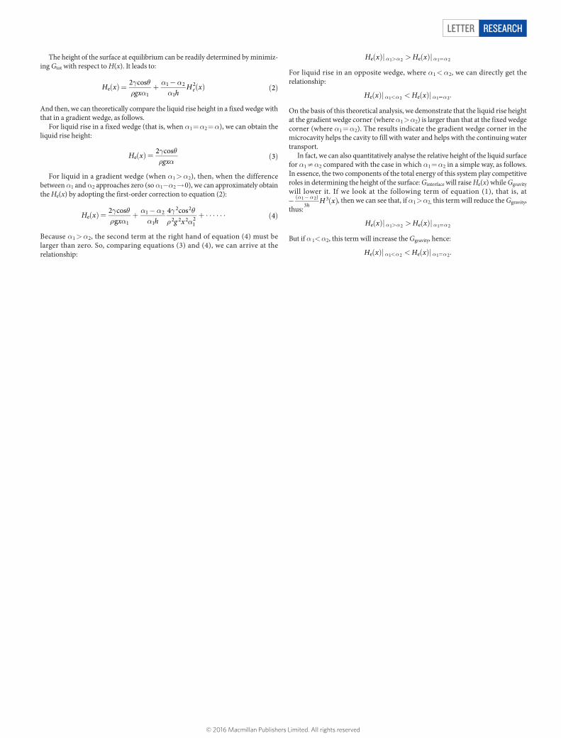
The height of the surface at equilibrium can be readily determined by minimiz-ing Gtot with respect to H(x). It leads to:
γ θρ α
α αα
( ) = +−
( ) ( )H xgx h
H x2 cos2ee
1
1 2
1
2
And then, we can theoretically compare the liquid rise height in a fixed wedge with that in a gradient wedge, as follows.
For liquid rise in a fixed wedge (that is, when α1 = α2 = α), we can obtain the liquid rise height:
γ θρ α
( ) = ( )H xgx
2 cos3e
For liquid in a gradient wedge (when α1 > α2), then, when the difference between α1 and α2 approaches zero (so α1−α2 → 0), we can approximately obtain the He(x) by adopting the first-order correction to equation (2):
γ θρ α
α αα
γ θρ α
( ) = +−
+ ⋅ ⋅ ⋅ ⋅ ⋅ ⋅ ( )H xx h g x
2 cosg
4 cos4e
1
1 2
1
2 2
2 2 212
Because α1 > α2, the second term at the right hand of equation (4) must be larger than zero. So, comparing equations (3) and (4), we can arrive at the relationship:
( )| > ( )|α α α α> =H x H xe e1 2 1 2
For liquid rise in an opposite wedge, where α1 < α2, we can directly get the relationship:
( )| < ( )|α α α α< =H x H xe e1 2 1 2.
On the basis of this theoretical analysis, we demonstrate that the liquid rise height at the gradient wedge corner (where α1 > α2) is larger than that at the fixed wedge corner (where α1 = α2). The results indicate the gradient wedge corner in the microcavity helps the cavity to fill with water and helps with the continuing water transport.
In fact, we can also quantitatively analyse the relative height of the liquid surface for α1 ≠ α2 compared with the case in which α1 = α2 in a simple way, as follows. In essence, the two components of the total energy of this system play competitive roles in determining the height of the surface: Ginterface will raise He(x) while Ggravity will lower it. If we look at the following term of equation (1), that is, at − ( )α α( − )H x
h331 2 , then we can see that, if α1 > α2, this term will reduce the Ggravity,
thus:
( )| > ( )|α α α α> =H x H xe e1 2 1 2
But if α 1< α2, this term will increase the Ggravity, hence:
( )| < ( )|α α α α< =H x H xe e1 2 1 2.
© 2016 Macmillan Publishers Limited. All rights reserved
LetterreSeArCH
Extended Data Figure 1 | The peristome surface and the microcavity. a, SEM image of a cross-section of the peristome, showing that two-order, regular radial ridges align perfectly to form regular two-order parallel hierarchical microgrooves. b, SEM image showing a side view of the
vertical section of a microcavity. The image reveals the microcavity’s geometry in the plane perpendicular to the peristome surface, and shows that the microcavity has a sharp edge with an angle, φ, of approximately 2° to 8°.
© 2016 Macmillan Publishers Limited. All rights reserved
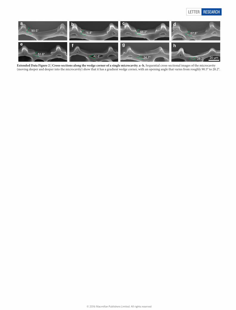
Letter reSeArCH
Extended Data Figure 2 | Cross-sections along the wedge corner of a single microcavity. a–h, Sequential cross-sectional images of the microcavity (moving deeper and deeper into the microcavity) show that it has a gradient wedge corner, with an opening angle that varies from roughly 90.5° to 28.2°.
© 2016 Macmillan Publishers Limited. All rights reserved
LetterreSeArCH
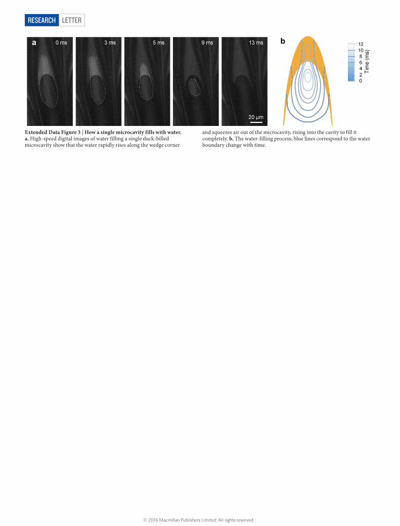
Extended Data Figure 3 | How a single microcavity fills with water. a, High-speed digital images of water filling a single duck-billed microcavity show that the water rapidly rises along the wedge corner
and squeezes air out of the microcavity, rising into the cavity to fill it completely. b, The water-filling process; blue lines correspond to the water boundary change with time.
© 2016 Macmillan Publishers Limited. All rights reserved
Letter reSeArCH
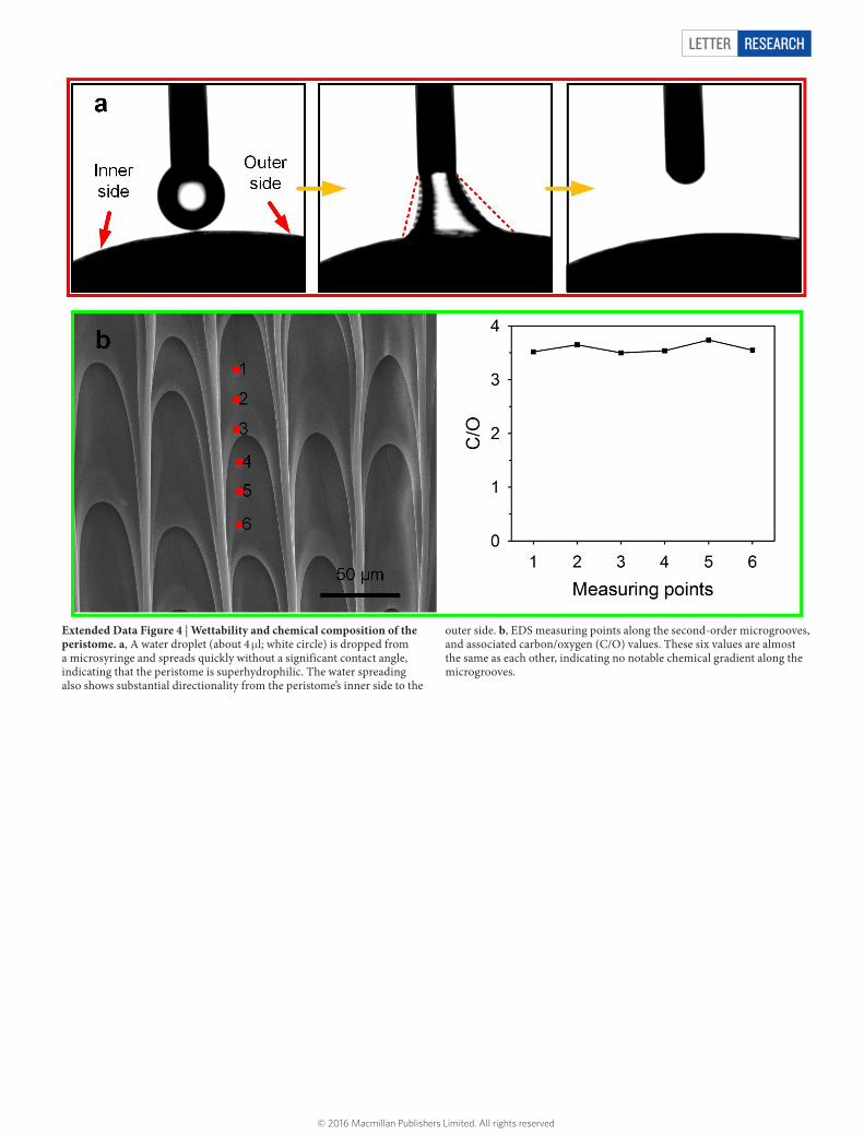
Extended Data Figure 4 | Wettability and chemical composition of the peristome. a, A water droplet (about 4 μl; white circle) is dropped from a microsyringe and spreads quickly without a significant contact angle, indicating that the peristome is superhydrophilic. The water spreading also shows substantial directionality from the peristome’s inner side to the
outer side. b, EDS measuring points along the second-order microgrooves, and associated carbon/oxygen (C/O) values. These six values are almost the same as each other, indicating no notable chemical gradient along the microgrooves.
© 2016 Macmillan Publishers Limited. All rights reserved
LetterreSeArCH
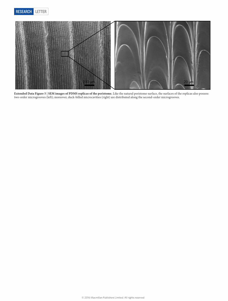
Extended Data Figure 5 | SEM images of PDMS replicas of the peristome. Like the natural peristome surface, the surfaces of the replicas also possess two-order microgrooves (left); moreover, duck-billed microcavities (right) are distributed along the second-order microgrooves.
© 2016 Macmillan Publishers Limited. All rights reserved
Letter reSeArCH
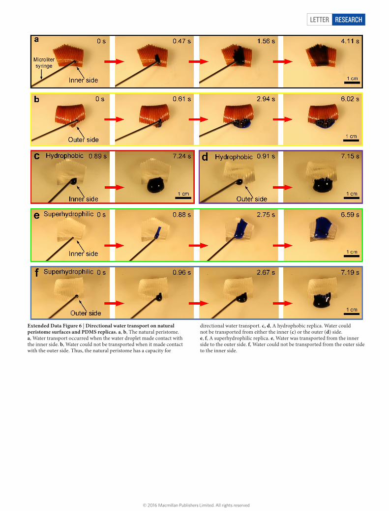
Extended Data Figure 6 | Directional water transport on natural peristome surfaces and PDMS replicas. a, b, The natural peristome. a, Water transport occurred when the water droplet made contact with the inner side. b, Water could not be transported when it made contact with the outer side. Thus, the natural peristome has a capacity for
directional water transport. c, d, A hydrophobic replica. Water could not be transported from either the inner (c) or the outer (d) side. e, f, A superhydrophilic replica. e, Water was transported from the inner side to the outer side. f, Water could not be transported from the outer side to the inner side.
© 2016 Macmillan Publishers Limited. All rights reserved
LetterreSeArCH
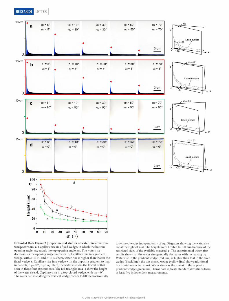
Extended Data Figure 7 | Experimental studies of water rise at various wedge corners. a, Capillary rise in a fixed wedge, in which the bottom opening angle, α1, equals the top opening angle, α2. The water rise decreases as the opening angle increases. b, Capillary rise in a gradient wedge, with α2 = 5°, and α1 > α2; here, water rise is higher than that in the fixed wedge. c, Capillary rise in a wedge with the opposite gradient to that in panel b; α2 = 90°, α1 < α2. Here, the water rise was the lowest of that seen in these four experiments. The red triangles in a–c show the height of the water rise. d, Capillary rise in a top-closed wedge, with α2 = 0°. The water can rise along the vertical wedge corner to fill the horizontally
top-closed wedge independently of α1. Diagrams showing the water rise are at the right of a–d. The heights were limited to 100 mm because of the restricted sizes of the available material. e, The experimental water-rise results show that the water rise generally decreases with increasing α1. Water rise in the gradient wedge (red line) is higher than that in the fixed wedge (black line); the top-closed wedge (yellow line) shows additional horizontal water transport. Water rise was the lowest in the opposite gradient wedge (green line). Error bars indicate standard deviations from at least five independent measurements.
© 2016 Macmillan Publishers Limited. All rights reserved
Letter reSeArCH
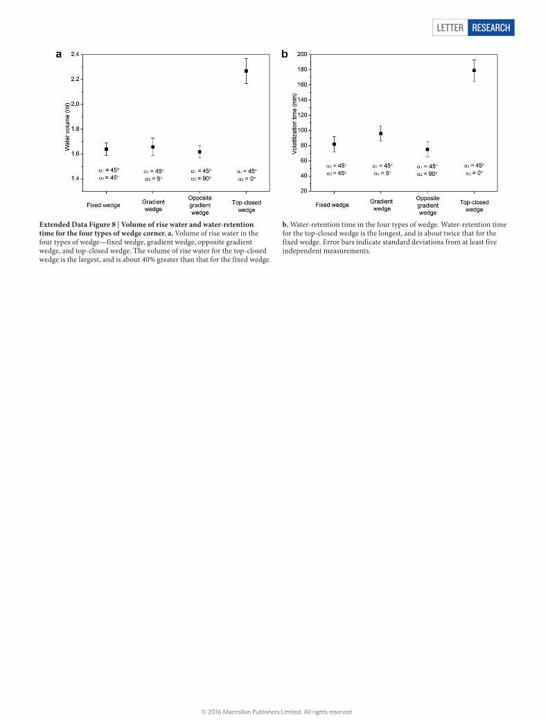
Extended Data Figure 8 | Volume of rise water and water-retention time for the four types of wedge corner. a, Volume of rise water in the four types of wedge—fixed wedge, gradient wedge, opposite gradient wedge, and top-closed wedge. The volume of rise water for the top-closed wedge is the largest, and is about 40% greater than that for the fixed wedge.
b, Water-retention time in the four types of wedge. Water-retention time for the top-closed wedge is the longest, and is about twice that for the fixed wedge. Error bars indicate standard deviations from at least five independent measurements.
© 2016 Macmillan Publishers Limited. All rights reserved
LetterreSeArCH
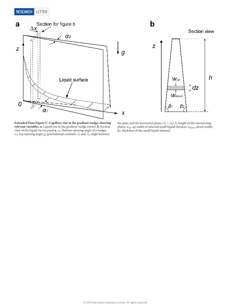
Extended Data Figure 9 | Capillary rise in the gradient wedge, showing relevant variables. a, Liquid rise in the gradient wedge corner. b, Section view of the liquid rise in panel a. α1, bottom opening angle of a wedge; α2, top opening angle; g, gravitational constant; β1 and β2, angle between
the plate and the horizontal plane (β1 = β2); h, height of the intersecting plates; wup, up width of selected small liquid element; wdown, down width; dz, thickness of the small liquid element.
© 2016 Macmillan Publishers Limited. All rights reserved