Embed Size (px)
Citation preview
ENDURANCE™ 50CONTINUOUS CAST PIPEVINYL ESTER FRP
Quantum Leap Manufacturing ProcessConley Composites has developed break-through proprietary technology in the manufacture of vinyl ester fiberglass reinforced thermoset we call “Contin-uous Cast Pipe” that produces a machine-made resin rich pipe to exact inside and outside diameter dimen-sions continuously. The process not only results in an extremely consistent product but also allows for pipe lengths up to 50 feet.
Superior to Competitors FRP PipeConley Endurance 50 “Continuous Cast Pipe” manufac-turing strategically places continuous glass reinforce-ment directly in the axis of stress loading, axial and hoop, providing outstanding strength in each axis.
The machine-positioned directional glass placement yields much greater stiffness offering higher axial ten-sile and beam bending capabilities for greater unsup-ported span situations and lower thermal expansion/contraction, while maintaining excellent pressure safety factor for hoop strength.
Resin Rich Nexus® 50 - 60 Mil Corrosion BarrierEndurance 50 internal corrosion barrier consists of 6 layers of Nexus® veil, each saturated with vinyl ester resin. The resin rich Nexus veil reinforcement pro-vides increased strength and ductility that isn’t easily cracked or fractured like “Fragile, non reinforced pure resin” is known to do with competitor’s pipe. Endur-ance pipe has been proven to provide over 2 times the impact resistance over competitor pipes as well.
Pressure and TemperatureEndurance 50 pipe is rated to 300 psi from -40°F to 200°F. Conley fittings also maintain the same pressure/ temperature rating as Endurance pipe.
External Resin Rich Nexus® Corrosion BarrierEndurance 50 pipe also incorporates a 10 mil resin rich Nexus external corrosion barrier on the O.D. which provides an excellent barrier to environment and airborne corrosives. Endurance pipe also contains a UV inhibitor to aid against ultraviolet radiation from sunlight.
MADE IN USA
Materials and ConstructionEndurance 50 is manufactured with two distinct layers; the 50 - 60 mil Nexus reinforced vinyl ester corrosion barrier with a heavy duty glass reinforce-ment saturated with Vinyl Ester resin.
The 50 - 60 mil internal corrosion barrier (inner liner) consists of a minimum of six layers of Nexus veil saturated with Vinyl Ester resin. The Nexus veil adds reinforcement to increase strength and ductility of the resin rich corrosion barrier.
The glass reinforcement, or cage, is manufactured with glass fiber bundles, pressure saturated with a highly chemical resistant formulation of premium vinyl ester resin to provide maximum exterior cor-rosion resistance. The unique pressure saturating process eliminates voids between fibers and resin. The fiberglass bundles are oriented in strict axial and hoop directions, which provide outstanding, stiffness and pressure capabilities.
The unique manufacturing process used to pro-duce Endurance 50 allows for lengths of straight spools to be manufactured up to 50 ft. allowing the end user to reduce the number of socket or flanged joints in the field.
FittingsConley fittings are filament wound, and have a minimum double Nexus veil reinforced Vinyl Ester internal corrosion resistant barrier (50 - 60 mils), filament wound glass reinforced structural cage, and a Nexus veil external corrosion barrier.
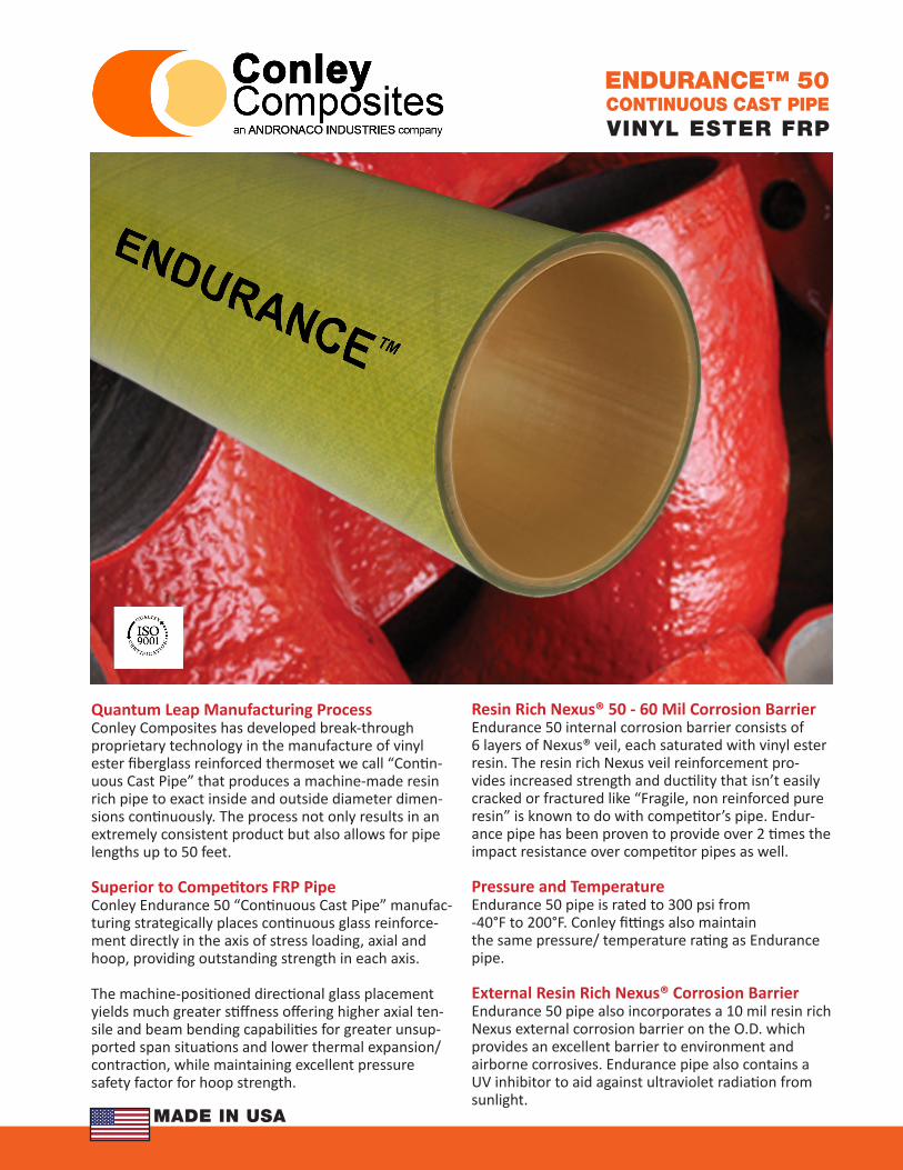
Connections - Straight Socket JointsStraight Adhesive Socket Joints are used with both pipe to fitting connections as well as pipe to pipe connections using couplings.
Flange connections are used to join the fiberglass pipe and fittings to other equipment. Flanges are designed for the operating pressure per the sys-tem requirements as a minimum. Flange dimen-sions conform to ANSI/ASME B16.5 150 lb drilling. Rotatable flanges (available on pipe spools only) exhibit enough strength to be connected to raised face surfaces (equipment connections, valves, etc.) and do not require a spacer ring to maintain a flat surface to the O.D of the flange. Where rotatable spool flanges are connected to any frp fittings, a full face gasket is required.
2 Conley Composites PHONE: 918-299-5051 FAX: 918-299-5907 www.ConleyFRP.com
ENDURANCE™ 50PRODUCT SCOPE
Gaskets and HardwareFlat washers shall be used between bolt heads or nuts and the back side of flanges.
Recommended gasket materials are a minimum of 1/8 inch in thickness with a suitable chemical resis-tance to the service. Gaskets shall have a Shore A hardness of 50 to 70.
PTFE envelope gaskets are not recommended. See the Conley Installation & Fabrication Manual for bolt torque requirements.
This type of joint shall be the only means of joining pipe and fittings. No tapering of pipe end shall be allowed.
FlangesFlanges are to be attached to a pipe section only with straight socket adhesive joints. Flang-es through 8” diameter shall be serrated for improved gasket sealing. Full face gaskets are required at any flanged connection to fittings. Ring gaskets are optional between rotating spool flanges and raised face connections.
Quality Assurance and InspectionConley’s Quality Assurance program is certified to ISO 9001-2008. All pipe is dimensionally inspected and measured as per Conley specifications. Fittings are inspected at each stage of manufacture for liner, reinforcement and external corrosion barrier thickness.
PIPE PIPE
STRAIGHT SOCKET PIPE COUPLING
ENDURANCE ADHESIVE
Conley Composites PHONE: 918-299-5051 FAX: 918-299-5907 www.ConleyFRP.com 3
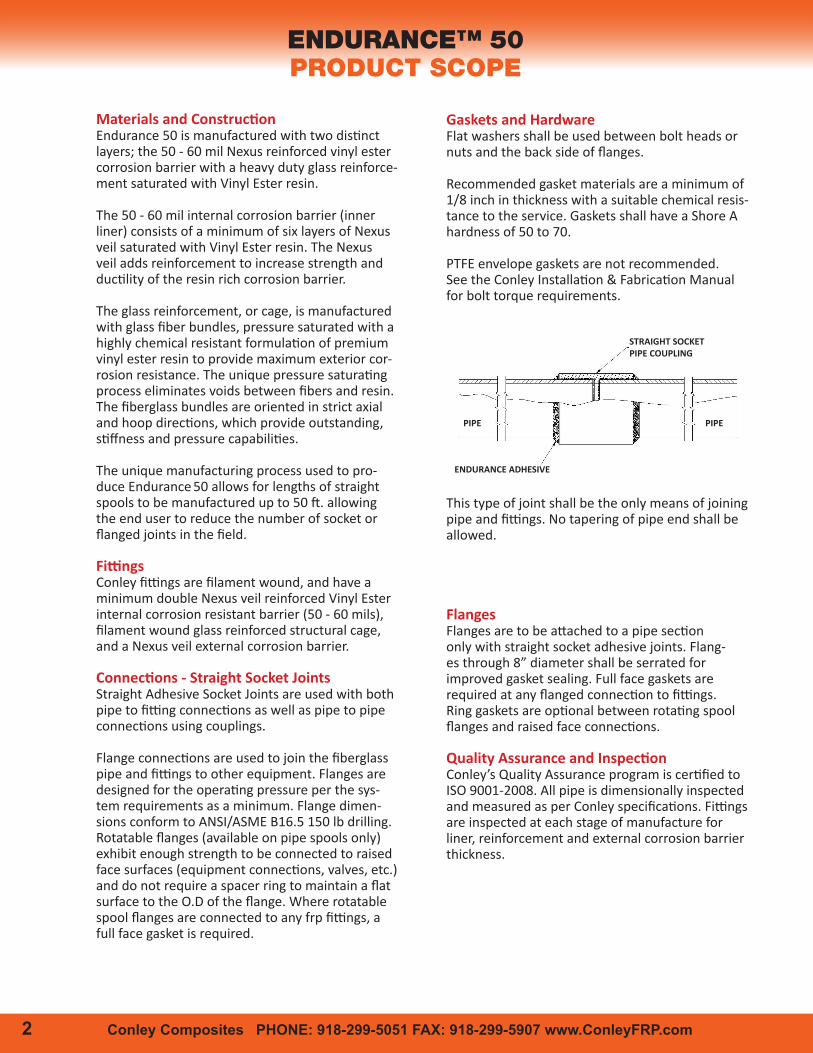
Nominal Dimensional Data
Nominal Pipe Size
in
O.D. I.D. Total Wall Thickness
ReinforcementThickness Weight Capacity
Internal Pressure at 75°F
Internal Pressure at 200°F
Vacuum Rating
at 200°F
in mm in mm in mm in mm lb/ft gal/ft psi psi psi
1 1.32 33.5 1.05 26.6 0.14 3.6 0.08 2.0 0.38 0.04 300 180 Full
1 1/2 1.88 47.8 1.60 40.6 0.14 3.6 0.08 2.0 0.55 0.11 300 180 Full
2 2.38 60.5 2.06 52.3 0.16 4.1 0.10 2.5 0.82 0.17 250 150 Full
3 3.50 88.9 3.07 78.0 0.22 5.5 0.16 3.9 1.65 0.38 250 150 Full
4 4.50 114.3 4.03 102.3 0.24 6.0 0.18 4.5 2.63 0.66 150 90 Full
6 6.63 168.3 6.07 154.1 0.28 7.1 0.22 5.6 4.23 1.50 150 90 Full
8 8.63 219.1 7.98 202.7 0.32 8.2 0.26 6.7 6.25 2.60 150 90 Full
ENDURANCE™ 50PROPERTIES
Nominal Pipe
Size in
Reinforcement End Area in2
Nominal Wall
End Area in2
Reinforcement Moment of Inertia in4
Reinforcement Section Modulus
in3
1 0.30 0.50 0.06 0.09
1 1/2 0.43 0.74 0.17 0.18
2 0.72 1.12 0.47 0.39
3 1.63 2.22 2.28 1.30
4 2.40 3.17 5.62 2.50
6 4.43 5.58 22.73 6.86
8 6.88 8.4 60.24 13.97
Properties of Pipe
Property75°F 24°C 175oF 80oC 200oF 93oC
psi MPa psi MPa psi MPa
Axial Tensile - ASTM D638
Ultimate Stress 66,000 460 46,200 320 39,600 270
Design Stress 16,500 115 11,550 80 9,900 68
Modulus of Elasticity 4.5 x 10⁶ 31,000 3.1 x 10⁶ 21,400 2.7 x 10⁶ 18,600
Poisson’s Ratio ν 0.39
Axial Compression - ASTM D695
Ultimate Stress 58,300 400 40,810 280 35,000 240
Design Stress 14,575 100 10,203 70 8,750 60
Modulus of Elasticity 5.1 x 10⁶ 35,160 4.9 x 10⁶ 33,780 4.8 x 10⁶ 33,090
Hydrostatic Burst - ASTM D1599
Ultimate Hoop Tensile Stress 13,000 90 9,100 63 7,800 54
Design Stress 3,250 23 2,275 16 1,950 13
Hoop Tensile Modulus of Elasticity 2.5 x 10⁶ 17,240 1.8 x 10⁶ 12,410 15 x 106 10,340
Beam Bending
Ultimate Stress 48,000 330 33,600 230 28,800 200
Design Stress 6,000 41 4,200 29 3,600 25
Modulus of Elasticity 4.0 x 10⁶ 27,580 2.8 x 10⁶ 19,310 2.4 x 10⁶ 16,550
Average Physical Properties
Thermal Expansion Coefficient ASTM D696 7.9 x 10⁻⁶ in/in/oF
Thermal Conductivity 0.1 BTU/hr-ft-oF
Specific Gravity - ASTM D792 1.71
Density - ASTM D792 0.062 lb/in3
Haze-Williams Coefficient 150
Manning’s Roughness Coefficient, n 0.009
Absolute Surface Roughness 0.0002
Cantilevered Bending 40,000 psi
Typical Properties
ENDURANCE COMPOSITE PIPEWITH COMPOSITE VALVE
SupportsPiping must be properly supported to prevent ex-cessive deflection and loading. Piping support spans depend on total pipe weight, i.e. liquid full weight de-pendent on fluid density, and operating temperatures. Elevated operating temperatures affects the bend-ing modulus of the piping material. The established maximum support spans ensure a mid-span deflection limited to 0.5” with an 8:1 safety factor for ultimate bending stress. Support conditions are defined as Type I, II, III and IV. Type II conditions are the most common, in which the pipe is analyzed as a continu-ous beam spanning two or more supports. Types I, III, and IV conditions refer to uniform distributed loads with single-span, four-spans, and fixed end supports respectively. Any additional external loads applied to the piping system such as insulation, wind or seismic loading require further analysis.
There are six key principals to properly support FRP Pipe:
1. Avoid Point Loading2. Do not exceed recommended minimum support spans3. Protect pipe from abrasion at support locations4. Support heavy valves and equipment independently5. Avoid excessive bending during handling and
installation6. Properly support vertical runs to avoid exces-
sive loading and cantilever loads
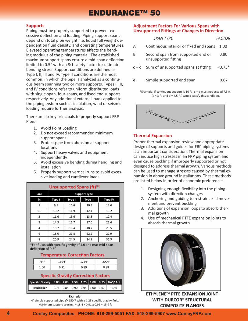
SPAN TYPE FACTOR
A Continuous interior or fixed end spans 1.00
B Second span from supported end or 0.80 unsupported fitting
c + d Sum of unsupported spans at fitting <0.75*
e Simple supported end span 0.67
*Example: If continuous support is 10 ft., c + d must not exceed 7.5 ft. (c = 3 ft. and d = 4.5 ft.) would satisfy this condition.
Adjustment Factors For Various Spans with Unsupported Fittings at Changes in Direction
4 Conley Composites PHONE: 918-299-5051 FAX: 918-299-5907 www.ConleyFRP.com
ENDURANCE™ 50
75oF 150oF 175oF 200oF
1.00 0.91 0.89 0.88
Temperature Correction Factors
Size Support Type
in Type I Type II Type III Type IV
1 9.1 10.6 10.8 13.6
1.5 10.2 11.9 12.1 15.2
2 11.6 13.6 13.8 17.4
3 14.3 16.7 17.0 21.4
4 15.7 18.4 18.7 23.5
6 18.6 21.8 22.2 27.9
8 20.9 24.5 24.9 31.3
Unsupported Spans (ft)(*)
*For fluids with specific gravity of 1.0 and max mid-span deflection of 0.5”
Specific Gravity 3.00 2.00 1.50 1.25 1.00 0.75 GAS/ AIR
Multiplier 0.76 0.84 0.90 0.95 1.00 1.07 1.40
Specific Gravity Correction Factors
Thermal ExpansionProper thermal expansion review and appropriate design of supports and guides for FRP piping systems is an important consideration. Thermal expansion can induce high stresses in an FRP piping system and even cause buckling if improperly supported or not designed to address thermal growth. Various methods can be used to manage stresses caused by thermal ex-pansion in above ground installations. These methods are listed below in order of economic preference:
1. Designing enough flexibility into the piping system with direction changes
2. Anchoring and guiding to restrain axial move-ment and prevent buckling
3. Additions of expansion loops to absorb ther-mal growth
4. Use of mechanical PTFE expansion joints to absorb thermal growth
Example:4” simply supported pipe @ 150°F with a 1.25 specific gravity fluid,
Maximum support spacing = 18.4 x 0.91 x 0.95 = 15.9 ft
ETHYLENE™ PTFE EXPANSION JOINT WITH DURCOR® STRUCTURAL
COMPOSITE FLANGES
d b a
b e
a a a b c
Recommended Allowable Bending Moments for 90o Elbows
Nominal Pipe size
Allowable Moment
Nominal Pipe size
Allowable Moment
in lb-ft in lb-ft
1 50 4 700
1 1/2 150 6 1,700
2 250 8 2,900
3 500
Elbow Strength
Conley Composites PHONE: 918-299-5051 FAX: 918-299-5907 www.ConleyFRP.com 5
Operating Temperature oF(1)
Size
100oF 125oF 150oF 175oF 200oF
Guide Spacing
Thermal End Load
Guide Spacing
Thermal End Load
Guide Spacing
Thermal End Load
Guide Spacing
Thermal End Load
Guide Spacing
Thermal End Load
in ft lbs ft lbs ft lbs ft lbs ft lbs
1 9.1 297 6.0 583 4.7 866 3.9 1,143 3.2 1,399
1 1/2 13.5 428 9.0 840 7.0 1,247 5.8 1,646 4.9 2,016
2 16.2 721 10.7 1,415 8.4 2,100 6.9 2,773 5.8 3,395
3 22.4 1,641 14.8 3,217 11.6 4,777 9.6 6,305 8.0 7,721
4 28.6 2,421 18.8 4,748 14.8 7,050 12.2 9,305 10.2 11,394
6 41.6 4,459 27.4 8,743 21.5 12,983 17.8 17,136 14.9 20,983
8 53.5 6,933 35.2 13,595 27.6 20,189 22.8 26,646 19.1 32,628
Restrained Thermal End Loads and Guide Spacing
(1) Based on an installation temperature of 75oF
Change in
Temperature oF
Change in Length
in/100 Ft
25 0.24
50 0.47
75 0.71
100 0.95
125 1.19
150 1.42
175 1.66
200 1.90
Thermal Growth
The coefficient of thermal expansion for EnduranceTM pipe is 7.9 x 10⁻⁶ in/in/oF. Expansion and contraction from changes in temperature in pipe runs can be determined by interpolation from the above data.
Primary and secondary guides are recommended adjacent to expansion joints and expansion loops to direct the movement of the piping and minimize axial misalignment.
Nominal Pipe Size in
Primary Guide in
Secondary Guide in
1 4 14
1 1/2 6 21
2 8 28
3 12 42
4 16 56
6 24 84
8 32 112
Distance from Expansion Joint and Expansion Loop to Primary and Secondary Guides
ENGINEERING DATA
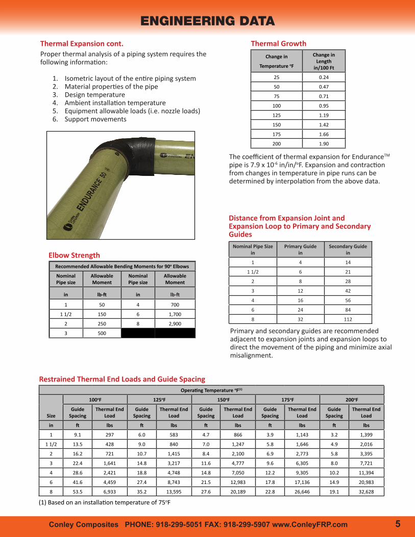
Thermal Expansion cont.Proper thermal analysis of a piping system requires the following information:
1. Isometric layout of the entire piping system2. Material properties of the pipe3. Design temperature4. Ambient installation temperature5. Equipment allowable loads (i.e. nozzle loads)6. Support movements
6 Conley Composites PHONE: 918-299-5051 FAX: 918-299-5907 www.ConleyFRP.com Conley Composites PHONE: 918-299-5051 FAX: 918-299-5907 www.ConleyFRP.com 7
Expansion Loop Leg Sizing
Sizein
90o
Elbow45o
ElbowTee
Thru RunTee
Thru Branch
1 2 0.8 1.5 5
1 1/2 3.7 1.9 2.7 8.5
2 5 2.4 3.3 11
3 7.5 3.9 4.7 16
4 10.5 5 6.5 21
6 15.5 8.3 10.25 33
8 19.5 11 14 43
Equivalent Feet of Head Loss Through Fittings
ENDURANCE™ 50
Nominal Pipe Size in
Flanged and Socket Fittings psi
1 300
1 1/2 300
2 300
3 300
4 300
6 250
8 250
Pressure Rating for Fittings up to 200 °F(1)
(1) Static Pressure Ratings
Nominal Pipe Size
in
Minimum “A” Leg Length (ft) for Total Thermal Expansion (in)
1” 2” 3” 4” 5” 6” 7” 8” 9” 10”
1 2.9 4 4.9 5.7 6.4 7 7.5 8 8.5 9
1.5 2.9 4.1 5 5.7 6.4 7 7.5 8.1 8.6 9
2 3.6 5.1 6.3 7.2 8.1 8.9 9.6 10.2 10.8 11.4
3 5.7 8 9.8 11.3 12.6 13.8 14.9 16 16.9 17.9
4 7.5 10.6 13 15 16.8 18.3 19.8 21.2 22.5 23.7
6 9.7 13.7 16.7 19.3 21.6 23.7 25.5 27.3 29 30.5
8 12.1 17 20.9 24.1 26.9 29.5 31.8 34 36.1 38
(1) Total Thermal Growth is ∆L1+∆L2 as shown below(2) “B” leg length is typically 1/2 “A” leg length
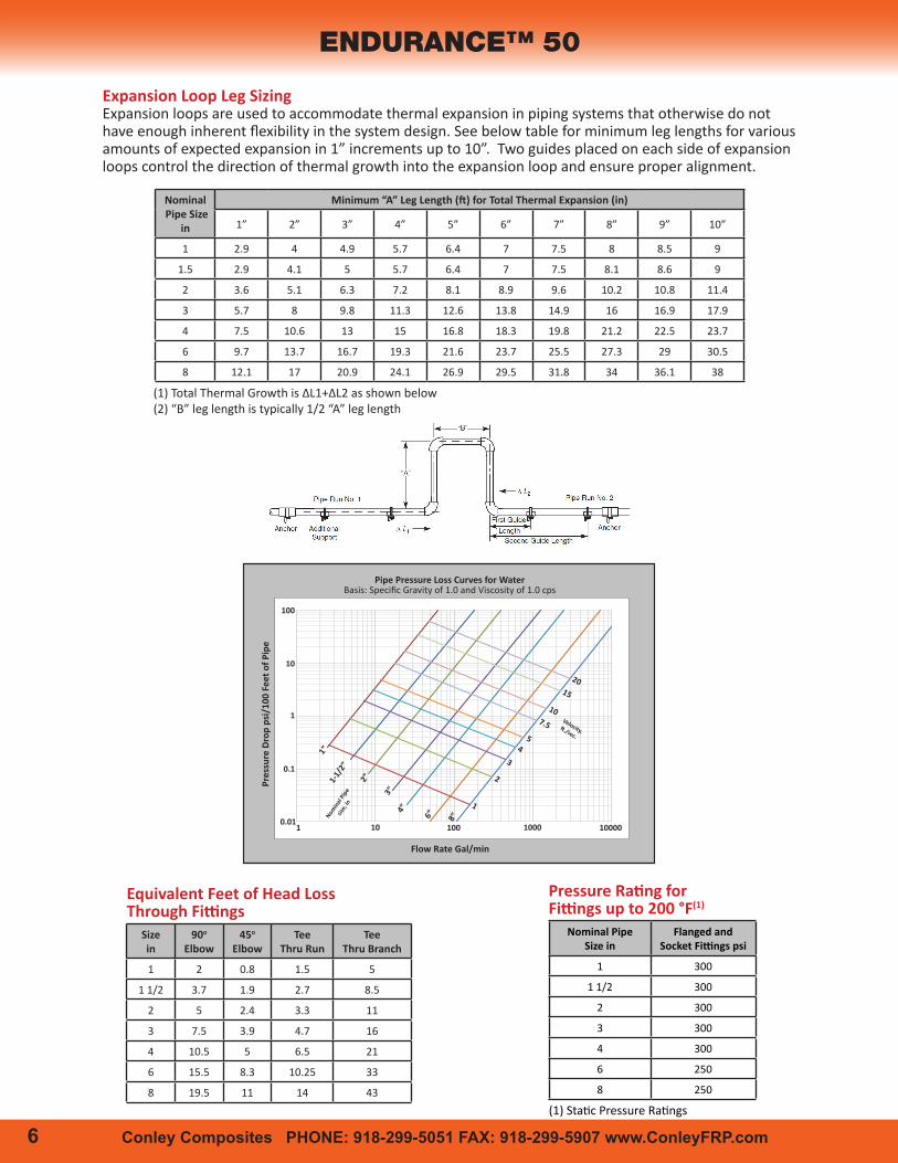
Pipe Pressure Loss Curves for WaterBasis: Specific Gravity of 1.0 and Viscosity of 1.0 cps
1”1-
1/2”
2”
3”4”
6” 8”
15
20
107.5
54
3
2
1
101 100 1000 10000
Pres
sure
Dro
p ps
i/10
0 Fe
et o
f Pip
e
0.01
0.1
1
10
100
Flow Rate Gal/min
Nomin
al Pip
esiz
e, in
Velocity,ft./sec.
Expansion loops are used to accommodate thermal expansion in piping systems that otherwise do not have enough inherent flexibility in the system design. See below table for minimum leg lengths for various amounts of expected expansion in 1” increments up to 10”. Two guides placed on each side of expansion loops control the direction of thermal growth into the expansion loop and ensure proper alignment.
6 Conley Composites PHONE: 918-299-5051 FAX: 918-299-5907 www.ConleyFRP.com Conley Composites PHONE: 918-299-5051 FAX: 918-299-5907 www.ConleyFRP.com 7
Raw Materials Standard Test MethodASTM D543 Test for Resistance of Plastics to Chemical ReagentsASTM D638 Test for Tensile Properties of PlasticsASTM D648 Test for Deflection Temperature of Plastics under LoadASTM D695 Test for Compressive Properties of Rigid PlasticsASMT D696 Test for Coefficient of Linear Thermal ExpansionASTM D790 Test for Flexural Properties of Plastics
Finished Product Standard Test MethodsASTM D1599 Test for Short-Time Rupture Strength of Plastic Pipe, Tubing and FittingsASTM D2105 Test for Longitudinal Tensile Proper ties of Reinforced Thermosetting Plastic Pipe and TubeASTM D2412 External Loading Properties of Plastic Pipe by Parallel Plate LoadingASTM D2925 Test for Beam Deflection of Fiberglass Pipe
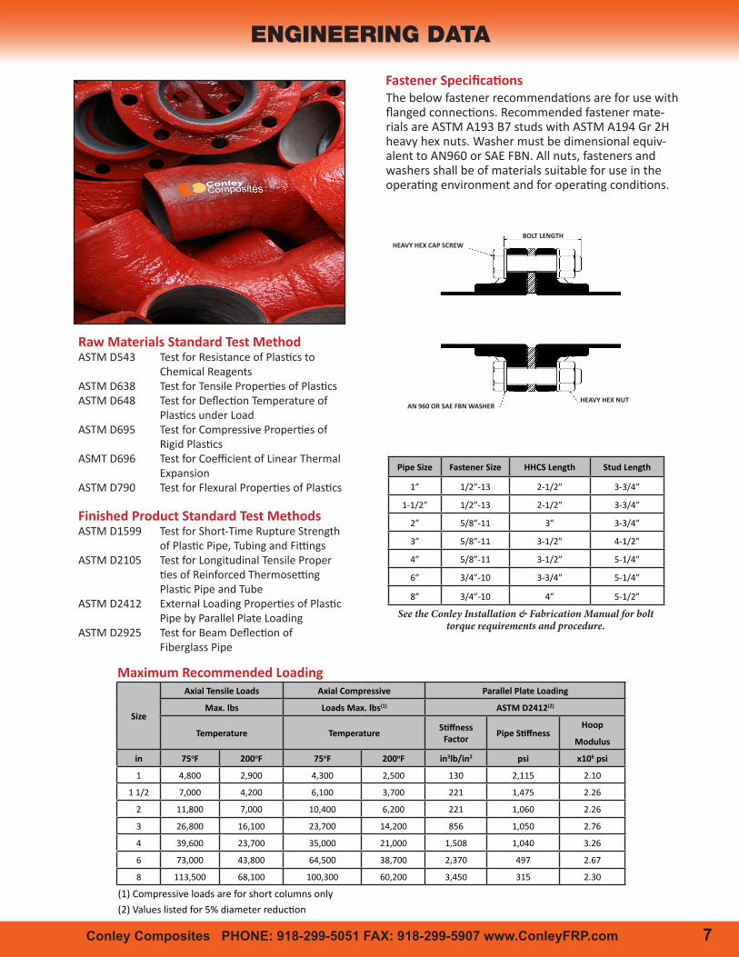
The below fastener recommendations are for use with flanged connections. Recommended fastener mate-rials are ASTM A193 B7 studs with ASTM A194 Gr 2H heavy hex nuts. Washer must be dimensional equiv-alent to AN960 or SAE FBN. All nuts, fasteners and washers shall be of materials suitable for use in the operating environment and for operating conditions.
Fastener Specifications
Pipe Size Fastener Size HHCS Length Stud Length
1” 1/2”-13 2-1/2” 3-3/4”
1-1/2” 1/2”-13 2-1/2” 3-3/4”
2” 5/8”-11 3” 3-3/4”
3” 5/8”-11 3-1/2” 4-1/2”
4” 5/8”-11 3-1/2” 5-1/4”
6” 3/4”-10 3-3/4” 5-1/4”
8” 3/4”-10 4” 5-1/2”
See the Conley Installation & Fabrication Manual for bolt torque requirements and procedure.
ENGINEERING DATA
Size
Axial Tensile Loads Axial Compressive Parallel Plate Loading
Max. lbs Loads Max. lbs(1) ASTM D2412(2)
Temperature Temperature Stiffness Factor Pipe Stiffness
Hoop
Modulus
in 75oF 200oF 75oF 200oF in3lb/in2 psi x106 psi
1 4,800 2,900 4,300 2,500 130 2,115 2.10
1 1/2 7,000 4,200 6,100 3,700 221 1,475 2.26
2 11,800 7,000 10,400 6,200 221 1,060 2.26
3 26,800 16,100 23,700 14,200 856 1,050 2.76
4 39,600 23,700 35,000 21,000 1,508 1,040 3.26
6 73,000 43,800 64,500 38,700 2,370 497 2.67
8 113,500 68,100 100,300 60,200 3,450 315 2.30
Maximum Recommended Loading
(1) Compressive loads are for short columns only (2) Values listed for 5% diameter reduction(1) Static Pressure Ratings
BOLT LENGTHHEAVY HEX CAP SCREW
AN 960 OR SAE FBN WASHERHEAVY HEX NUT
2795 East 91st Street Tulsa, Oklahoma 74137 Phone: 918-299-5051 Fax: 918-299-5907 www.ConleyFRP.com
CONLEY COMPOSITES LLC. INFORMATION IS BASED ON TECHNI-CAL DATA AND TESTING THAT CONLEY COMPOSITES BELIEVES TO BE RELIABLE AND IS SUBJECT TO CHANGE WITHOUT NOTICE. THE INFORMATION IS INTENDED FOR USE BY PERSONS HAVING TECHNICAL SKILL, AND AT THEIR OWN DISCRETION AND RISK. SINCE CONDITIONS OF PRODUCT ARE OUTSIDE OF CONLEY COMPOSITES CONTROL, CONLEY COMPOSITES MAKES NO WAR-RANTIES, EXPRESS OR IMPLIED, AND ASSUMES NO LIABILITY IN CONNECTION WITH ANY USE OF THIS INFORMATION. DURCOR® IS A REGISTERED TRADEMARK OF PUREFLEX® INC. FLEXIJOINT® IS A REGISTERED TRADEMARK OF ETHYLENE LLC. NEXUS® IS A REGIS-TERED TRADEMARK OF PRECISION FABRICS GROUP, INC.
END-517
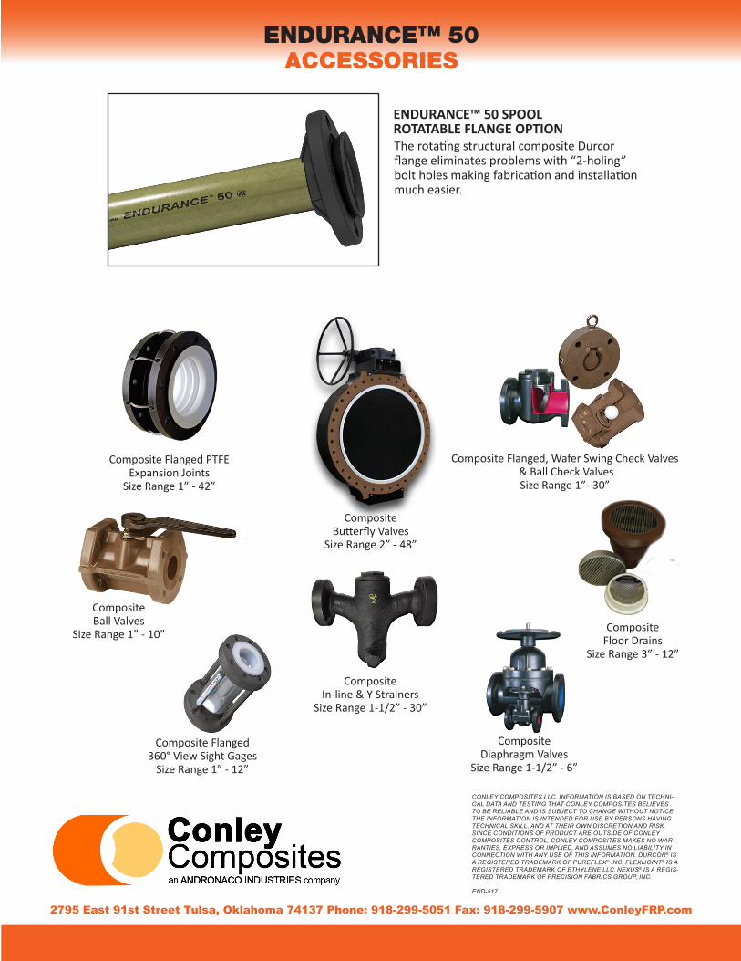
ENDURANCE™ 50 SPOOLROTATABLE FLANGE OPTION
ENDURANCE™ 50ACCESSORIES
The rotating structural composite Durcor flange eliminates problems with “2-holing” bolt holes making fabrication and installation much easier.
Composite Flanged PTFE Expansion Joints
Size Range 1” - 42”
Composite Butterfly Valves
Size Range 2” - 48”
Composite Flanged, Wafer Swing Check Valves & Ball Check ValvesSize Range 1”- 30”
Composite Ball Valves
Size Range 1” - 10”
Composite Flanged360° View Sight Gages
Size Range 1” - 12”
Composite In-line & Y Strainers
Size Range 1-1/2” - 30”
Composite Diaphragm Valves
Size Range 1-1/2” - 6”
Composite Floor Drains
Size Range 3” - 12”