Embed Size (px)
Citation preview

Permission to make digital/hard copy of part of all of this work for personal orclassroom use is granted without fee provided that the copies are not made ordistributed for profit or commercial advantage, the copyright notice, the title of thepublication, and its date appear, and notice is given that copying is by permissionof ACM, Inc. To copy otherwise, to republish, to post on servers, or to redistributeto lists, requires prior specific permission and/or a fee.© 2003 ACM 0730-0301/03/0700-0578 $5.00
Continuous Capture of Skin Deformation
Peter Sand∗ Leonard McMillan† Jovan Popovic
Laboratory for Computer ScienceMassachusetts Institute of Technology
†University of North Carolina, Chapel Hill
Figure 1: We extract silhouettes from video sequences to build a deformable skin model that can be animated with new motion.
Abstract
We describe a method for the acquisition of deformable human ge-ometry from silhouettes. Our technique uses a commercial track-ing system to determine the motion of the skeleton, then estimatesgeometry for each bone using constraints provided by the silhou-ettes from one or more cameras. These silhouettes do not give acomplete characterization of the geometry for a particular point intime, but when the subject moves, many observations of the samelocal geometries allow the construction of a complete model. Ourreconstruction algorithm provides a simple mechanism for solvingthe problems of view aggregation, occlusion handling, hole filling,noise removal, and deformation modeling. The resulting model isparameterized to synthesize geometry for new poses of the skele-ton. We demonstrate this capability by rendering the geometry formotion sequences that were not included in the original datasets.
CR Categories: I.3.7 [Computer Graphics]: Three-DimensionalGraphics and Realism—Animation; I.4.8 [Image Processing andComputer Vision]: Scene Analysis—Shape
Keywords: motion capture, skin modeling, human animation
1 Introduction
A digital replica of a moving human body has applications in videogames, teleconferencing, automated news shows, and filmmaking.For example, the physical appearance of a celebrity actor could berecorded and later animated with acrobatic motions controlled by ananimator or performed by a stunt double in a motion-capture suit.In current filmmaking, this application requires extensive manuallabor to position and adjust skin around each bone and muscle. In
∗77 Massachusetts Avenue, Cambridge, MA 02139
some cases, months are spent matching a virtual character to anexisting actor [Stokdyk et al. 2002].
Our goal is to build a skin model that replicates the skin deforma-tions of a particular person. The technique described in this paperbuilds this model automatically from video of the subject and mo-tion data that describes how the subject’s skeleton moves through-out the video recording. To build the model from this data, weexploit the idea that video of a moving person provides many ob-servations of the same surface. A single set of silhouettes (evenfrom several viewpoints) provides a highly incomplete characteri-zation of the geometry. By having the subject move through manydifferent poses, local configurations of the body parts are repeated,allowing the construction of a complete model.
Our main contribution is a method of gathering silhouette ob-servations such that a simple reconstruction algorithm can create acomplete deformable model, parameterized in a way that is usefulfor animation. We do not contribute new techniques in the areas ofskin representation and skin interpolation, but in ways of quicklyacquiring skin data. By using the right combination of prior tools,we substantially simplify the problem of generating a 3D modelfrom moving silhouettes.
Our skin model, described in Section 3, represents a complexarticulated figure using a collection of elongated deformable prim-itives. Our acquisition algorithm, described in Section 4, uses thesilhouettes to provide constraints on the possible body geometry.The reconstruction algorithm, described in Section 5, uses theseconstraints to find a model of the skin deformations, parameterizedwith the motion of the skeleton. This parameterization allows ani-mation of the skin with new motion data.
2 Related Work
The most general 3D reconstruction systems attempt to build amodel of the scene at each successive time frame, allowing theacquisition of moving objects. These systems use vision meth-ods such as binocular stereo [Nebel et al. 2001] and voxel color-ing [Vedula et al. 2002]. For certain kinds of scenes, the geometrycan be reasonably represented using a visual hull: the space carvedabout by silhouettes from a set of viewpoints [Matusik et al. 2000;Wurmlin et al. 2002].
Some of these methods make frame-to-frame comparisons of thegeometry [Wurmlin et al. 2002; Vedula et al. 2002], but they do notaccumulate observations to improve the geometry. The strength ofgathering information from temporally distinct views is illustratedin recent work in real-time model acquisition, in which a rigid ob-
578
ject can be moved while it’s digitized [Rusinkiewicz et al. 2002].Real-time feedback and freedom of movement allow the operatorto fill in holes and build a complete model. While this technique al-lows accurate and complete models to be generated from multipleobservations of an object, it is limited to rigid objects.
Factorization techniques, in contrast, can build models of de-forming objects. Surface deformations are represented as a lin-ear combination of prototype shapes, found via matrix factoriza-tion [Bregler et al. 2000; Brand 2001; Torresani and Bregler 2002].A matrix of image observations is factored into a matrix of posevectors, which defines the object’s motion, a matrix of geome-try vectors, which defines the basis shapes, and a vector of basisweights, which defines the deformation of the object. While thesefactorization methods are quite powerful, they have not been ap-plied to capture deformations of an entire human body.
To overcome the difficulties of general reconstruction, a modelof an object class can be fit to observations of a particular object.For example, numerous methods reconstruct and reanimate the hu-man face [Guenter et al. 1998; Cootes et al. 1998; Blanz and Vet-ter 1999]. These techniques are successful at modeling a range ofhuman faces, but would be difficult to extend to capturing an en-tire human body, due to large-scale occlusions and deformations.Nonetheless, they would be an excellent complement to our currentsystem, which cannot capture facial expressions.
Several systems reconstruct human bodies by fitting prior modelto observations of a moving person. For tracking applications,simple models consisting of ellipsoids can be fit using silhouettes[Mikic et al. n. d.]. Plankers and Fua [2001] use an elaborateanatomical model, in which the skin surface is defined as the levelset of Gaussians rigidly attached to a skeleton. The dimensionsof these Gaussians are optimized according to observations fromthe silhouettes and stereo depth estimates. Kakadiaris and Metaxas[1993] use a pre-defined protocol of motions to extract 2D contoursof body parts. These 2D contours can deform for different posesand be interpolated to obtain an approximation of the 3D geometry.
Allen and colleagues [2002] acquire multiple poses of the hu-man body using a 3D laser scanner to obtain a high level of detailand accuracy. Each of the reconstructed poses is related to a skele-tal configuration through the use of dots placed on the skin. Newposes are then synthesized by interpolating nearby key poses. Thismethod has successfully created animations of the upper body, butit requires a substantial amount of time and effort in order to ac-quire hundreds of 3D range scans. In contrast, our system acquiresthe deformation automatically as the subject moves freely throughvarious poses, building a complete model using only a few min-utes of motion. However, because our models are built from video,rather than laser scanning, we do not obtain the same level of detail.
Like many of these acquisitions systems, our work uses inter-polation to combine models of different poses. These interpolationtechniques (such as [Lewis et al. 2000; Sloan et al. 2001; Wang andPhillips 2002]) vary in the interpolation mechanisms, the particularquantities being interpolated, and the way in which the skeletondrives the interpolation. Several of these papers give theoreticalresults on the relative strengths and limitations of different repre-sentations of geometry and deformation—a subject not addressedin this paper. Instead, we focus on how to position and reconstructprototype shapes in a fast and automatic manner.
3 Skin Model
Our skin model simplifies the complex process of acquiring geom-etry of a moving human body. We represent the skin surface usingpoints along needles that are rigidly attached to a skeleton. Thismodel describes complex areas near joins by combining nearbysamples. Deformation is parameterized with a configuration spacefor each bone.
3.1 Deformable Primitives
We represent the geometry of an articulated human figure using acollection of elongated deformable primitives. Each deformableprimitive consists of a rigid axis, which usually corresponds to abone in the skeleton, and a set of needles, which are rigidly attachedto the axis. Each needle originates at a point along the axis andextends outward in a fixed direction with respect to the axis.
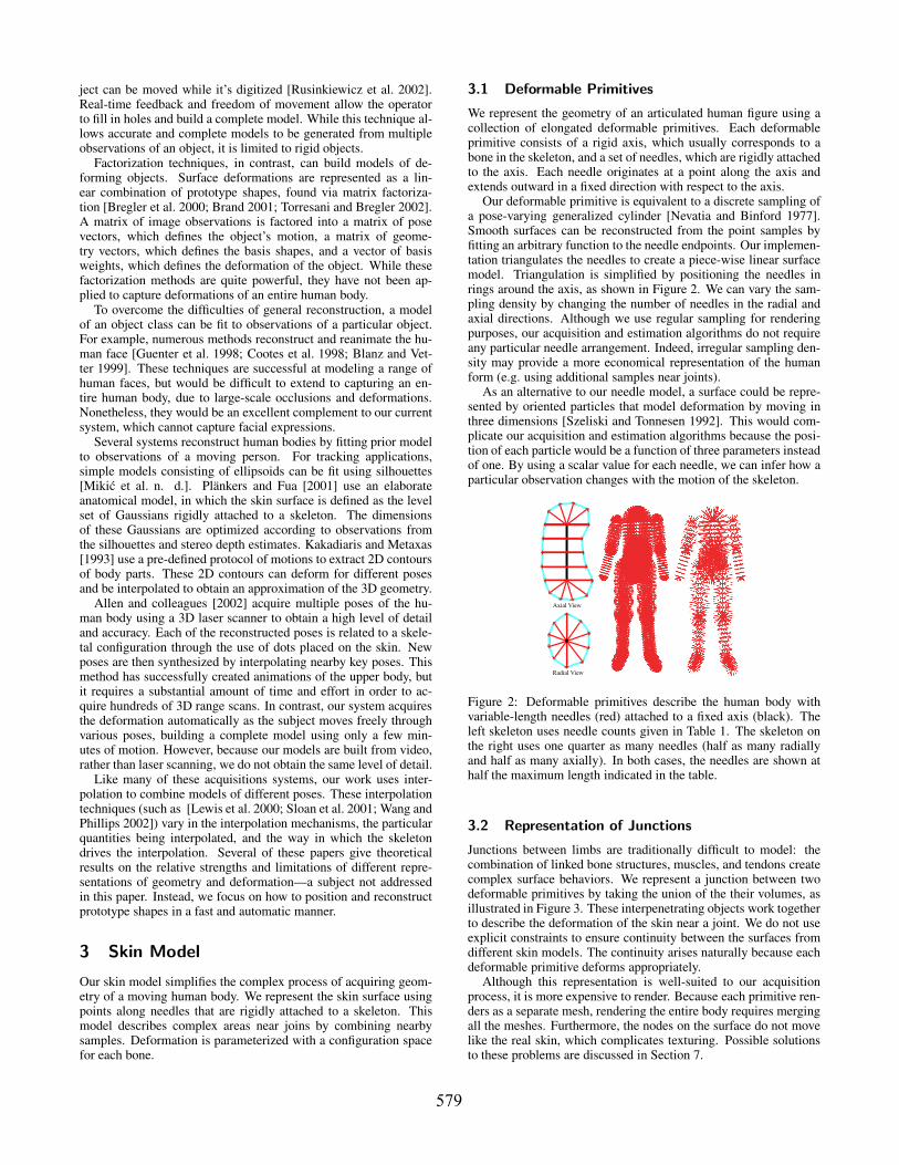
Our deformable primitive is equivalent to a discrete sampling ofa pose-varying generalized cylinder [Nevatia and Binford 1977].Smooth surfaces can be reconstructed from the point samples byfitting an arbitrary function to the needle endpoints. Our implemen-tation triangulates the needles to create a piece-wise linear surfacemodel. Triangulation is simplified by positioning the needles inrings around the axis, as shown in Figure 2. We can vary the sam-pling density by changing the number of needles in the radial andaxial directions. Although we use regular sampling for renderingpurposes, our acquisition and estimation algorithms do not requireany particular needle arrangement. Indeed, irregular sampling den-sity may provide a more economical representation of the humanform (e.g. using additional samples near joints).
As an alternative to our needle model, a surface could be repre-sented by oriented particles that model deformation by moving inthree dimensions [Szeliski and Tonnesen 1992]. This would com-plicate our acquisition and estimation algorithms because the posi-tion of each particle would be a function of three parameters insteadof one. By using a scalar value for each needle, we can infer how aparticular observation changes with the motion of the skeleton.
Axial View
Radial View
Figure 2: Deformable primitives describe the human body withvariable-length needles (red) attached to a fixed axis (black). Theleft skeleton uses needle counts given in Table 1. The skeleton onthe right uses one quarter as many needles (half as many radiallyand half as many axially). In both cases, the needles are shown athalf the maximum length indicated in the table.
3.2 Representation of Junctions
Junctions between limbs are traditionally difficult to model: thecombination of linked bone structures, muscles, and tendons createcomplex surface behaviors. We represent a junction between twodeformable primitives by taking the union of the their volumes, asillustrated in Figure 3. These interpenetrating objects work togetherto describe the deformation of the skin near a joint. We do not useexplicit constraints to ensure continuity between the surfaces fromdifferent skin models. The continuity arises naturally because eachdeformable primitive deforms appropriately.
Although this representation is well-suited to our acquisitionprocess, it is more expensive to render. Because each primitive ren-ders as a separate mesh, rendering the entire body requires mergingall the meshes. Furthermore, the nodes on the surface do not movelike the real skin, which complicates texturing. Possible solutionsto these problems are discussed in Section 7.
579

Figure 3: We represent an elbow using overlapping deformableprimitives for the upper arm and forearm. Both primitives deformas the elbow bends, maintaining continuity in the junction. Theimage on the right shows how the segments overlap in a completebody.
3.3 Parameterization of Skin Deformation
The length of each needle can depend on parameters that influenceskin deformation. For example, we may wish that the geometry ofthe upper arm varies as a function of the angle of the elbow andas a function of the angle of the shoulder. We could also make thegeometry vary as a function of muscle force (for muscular people)and the direction of gravity (for heavy people).
The results in this paper demonstrate deformations caused bythe motion of a skeleton. Each deformable primitive has a limitedconfiguration space that is a subset of the configuration of the entirebody. For example, the deformation of the left arm does not dependon the configuration of the right knee. We make this assumption tocope with the combinatorial complexity of the human pose space.By decoupling remote parts of the body, we can capture a widerange of deformations in a short amount of time.
To avoid the issues of joint-angle representation, we use markercoordinates to determine the configuration space. For example, theconfiguration of the right thigh depends on markers attached to thehip and the right calf, where the positions are expressed with respectto the local coordinate frame of the thigh bone. Table 1 summarizesthe configuration parameters for each deformable primitive.
4 Acquisition of Skin Observations
Our system extracts surface observations by combining informationfrom two separate sources: a commercial motion-capture systemand a set of standard video cameras. The motion-capture systemtracks reflective markers, which are used to compute the motionof each bone. Because the motion-capture cameras in our systemuse infrared strobes and filters, they are not suitable for silhouetteextraction. Instead, the silhouettes are extracted from one or morevideo cameras placed around the motion-capture workspace. Oursystem does not require any special camera arrangement; we posi-tion the cameras such that the subject is within the view throughoutthe motion, as shown in Figure 4.
Our system first calibrates and synchronizes the video and themotion data. It then combines these two data sources to measurethe intersection of needles and silhouettes. The reconstruction al-gorithm described in Section 5 subsequently processes the resultingmeasurements to parameterize the motion of the skin surface.
4.1 Calibration
Camera calibration relates the motion data (the location of markersand bones in a single 3D coordinate system) to the image coor-dinates of each camera. We perform calibration using a simple de-
Figure 4: The input video includes images of the subject in a widevariety of poses. As discussed in Section 6.6, the quality of the finalmodel depends on the range of motion in the training sequences.
vice, shown in Figure 5, which allows us to match an image point toan identical point in the motion data. The calibration process startswith synchronization of video and motion data. We move the cali-bration device up and down in a plane roughly parallel to the imageplane of a particular camera and correlate the vertical image coor-dinate with the vertical world coordinate. Once synchronized, weresample the motion-capture data to obtain a sequence of matchingimage pi ∈ ℜ2 and world wi ∈ ℜ3 points. The mapping betweenthese points depends on camera position, camera orientation, fo-cal length, aspect ratio, and radial distortion. Our system estimatesthese parameters by minimizing Euclidean error in image space:
minq, f ,a,c,r
∑i||pi−Dc,r(Pq, f ,awi)||
The matrix Pq, f ,a describes a perspective projection (parameter-ized by camera pose q, focal length f , and aspect ratio a) and thefunction Dc,r() describes first-order radial distortion (with centerof distortion c and a distortion coefficient r). For simplicity we si-multaneously optimize the parameters using the downhill simplexmethod [Nelder and Mead 1965]. The method quickly converges toa solution that obtains a sub-pixel RMS error over several hundred(wi, pi) input points.
Figure 5: Our calibration device consists of a green sphere withtwo motion-capture markers. We find the center of the sphere inimage coordinates by detecting green pixels. We find the centerof the sphere in world coordinates by taking the midpoint of thetwo marker positions. This gives a single correspondence that bevaries through time to obtain a number of spatial correspondencesfor calibration.
4.2 Silhouette Extraction
Our system uses standard background subtraction to obtain silhou-ettes from video data. For each pixel, background subtraction findsthe difference between the current frame and an empty background
580

Configuration Dim. of Radial Axial MaximumBone Name Depends On Config. Space Needles Needles Needle LengthTorso Upper Arms, Hips 9 30 30 30cmHips Torso, Thighs 9 30 30 30cmRight Upper Arm Torso, Right Forearm 6 20 20 15cmLeft Upper Arm Torso, Left Forearm 6 20 20 15cmRight Forearm Right Upper Arm 3 20 20 10cmLeft Forearm Left Upper Arm 3 20 20 10cmRight Thigh Hips, Right Calf 6 20 30 20cmLeft Thigh Hips, Left Calf 6 20 30 20cmRight Calf Right Thigh, Right Foot 6 20 30 15cmLeft Calf Left Thigh, Left Foot 6 20 30 15cmRight Foot Right Calf 3 20 20 15cmLeft Foot Left Calf 3 20 20 15cm
Table 1: Each deformable primitive is described with a configuration space (Section 3.3), needle counts (Section 3.1), and a maximum needlelength (Section 4.3).
frame and labels pixels with a high difference as part of the fore-ground. Our system uses a large subtraction threshold to overcomeshadows and video compression artifacts. The threshold near thehead is smaller to account for the closeness of skin color to thebackground (where the head position is determined directly fromthe motion capture data). These thresholds are sufficiently robustthat the same values can be used across multiple cameras and acrossmultiple sequences.
We use the silhouettes and camera calibration to synchronize thevideo data and motion data for a human subject. Our system usesa simplex optimizer (the same one used for camera calibration) tominimize an objective function that measures the image-space dis-tance from projected arm and leg markers to the silhouettes over anumber of video frames.
4.3 Accumulation of Needle Observations
After calibrating and synchronizing the video and motion data, thesystem projects each needle into each video frame to compute theneedle length from its intersection with the silhouette. Starting atthe origin of the needle, we traverse the image outward until theneedle projection leaves the silhouette, as illustrated in Figure 6.If the traversal extends beyond a prescribed maximum length, themeasurement is discarded. Thus the system discards observationsfor needles that are nearly perpendicular to the image plane or thatextend into distant parts of the body. Our maximum length values(specified in Table 1) are relatively large; the same values can beused for a wide variety of people.
For each needle length observation, we also record the bone’scurrent position in configuration space, as described in Section 3.3.By annotating each observation with the conditions under whichthe observation was made (a location in configuration space), wecan estimate skin deformation, as described in the next section.
5 Skin Reconstruction
The acquisition process accumulates observations of needlelengths. Subsequent reconstruction will refer only to these obser-vations, not the original video and motion data. Because the needleobservations do not give a complete description of the geometry atany time instant, reconstruction integrates observations over timeto obtain a complete model. Skin reconstruction determines whichobservations are valid measurements of the true needle length andwhich are invalid due to occlusion.
As shown in Figure 6, multiple types of invalid observations oc-cur. In each case, the measurements overestimate the true geome-
(a)
(b)
A
B
Camera Center
1
2
Figure 6: Left: To obtain a needle length observation, we projectthe needle into the image plane. We traverse the image along theneedle (from (a) towards (b)), to find the image space distance fromthe bone to the edge of the silhouette (in blue). This length is con-verted to a world space distance and later used to estimate defor-mation. Right: The black lines indicate the silhouette observed forthe pair of objects A and B. The length of needle 1 is overestimatedbecause the background is occluded by object A while the length ofneedle 2 is overestimated because the background is occluded byobject B. In general, the silhouette provides an upper bound on thegeometry.
try. Thus, by taking the minimum of these observations, we find theleast upper bound on the true geometry. Equivalently, we seek themaximal geometry that is consistent with the observations.
Because the silhouettes provide an upper bound on the geometry,the needle data effectively has a one-sided error. This contrasts thetwo-sided errors that occur with other reconstruction methods (e.g.stereo and factorization). This is a key element of our approach: aone-sided error can be removed more easily than a two-sided error.
The reconstruction algorithms uses the following design goals tocompute the maximal consistent geometry:
occlusion handling. Invalidate measurements that are incorrectbecause of visibility.
time aggregation. Combine multiple observations to completepartially observed shapes.
hole filling. Borrow an observation from a nearby configuration ifthere are no valid observations for a given configuration.
noise filtering. Remove outliers caused by errors in silhouette ex-traction and motion capture.
deformation modeling. Obtain geometry estimates that varysmoothly with configuration.
581

5.1 Deformation Model
The skin deforms with the motion of the skeleton. We model this re-lationship with a set of functions li j(x) that each map a joint config-uration x to an appropriate needle length, where the index i rangesover all deformable primitives in the body and the index j rangesover all needles in that primitive. The configuration point x ∈ Cidescribes the configuration of a deformable primitive as discussedin Section 3.3. We represent lengths li j(x) using a normalized ra-dial basis function (NRBF) [Broomhead and Lowe 1988], whichinterpolate prototype shapes via distance-weighted averaging:
li j(x) =∑k vi jkK(x, pik)
∑k K(x, pik),
where index k ranges over all prototypes. Each prototype has alocation pik in the configuration space Ci and a shape vi jk , whichgives the length of the jth needle in the kth prototype of primitive i.The weighting function K(x1,x2) is an arbitrary distance kernel. Wechoose a Gaussian kernel because it is well-behaved over a rangeof dimensionalities.
This formulation obtains better extrapolation than non-normalized radial basis functions (which go to zero as they movefurther from the basis locations). The NRBF extrapolates by repli-cating the nearest values outside the realm of observed data. Inthe context of skin modeling, we prefer this kind of extrapolationbecause it avoids generating extreme geometry for extreme config-urations. Allen and colleagues [2002] use nearest-neighbor inter-polation for the same reason.
Although NRBF interpolation is simple and effective, more so-phisticated techniques have been developed for interpolating skinprototypes [Lewis et al. 2000; Sloan et al. 2001; Wang and Phillips2002]. The use of these other techniques could provide better re-sults (at the cost of increased conceptual complexity).
We use the term prototype because it is a conceptually usefulway to think about our model. Many other methods represent defor-mation via the interpolation of pre-defined prototypes [Lewis et al.2000; Sloan et al. 2001; Blanz and Vetter 1999; Allen et al. 2002].In our work, however, the prototypes are not pre-defined. Their lo-cations are randomly scattered in the configuration space and theirshapes are inferred from the data.
5.2 Prototype Locations
Before we estimate the prototype shapes (vi jk) we neeed to deter-mine the prototype locations (pik). We want the prototypes to bewell scattered across the space of training poses so that we canmodel the complete range of observed deformations.
For each deformable primitive, we greedily select prototype lo-cations from among the set of observed points in the configurationspace. We choose the first prototype location pi0 at random from theknown configurations. We then select pi1 to be the furthest (in Eu-clidean distance) from pi0 and proceed by selecting each additionalprototype pik to be furthest from the previously selected prototypes(pil for l < k). An exhaustive search, which is linear in the num-ber of datapoints and quadratic in the number of prototypes, canbe used to find each prototype location. The results are illustratedin Figure 7. Unlike clustering the observed configurations or sam-pling from the observed configurations, this results in prototypesbeing placed even where the data density is low.
5.3 Prototype Shapes
Once each prototype has been assigned to a particular location inconfiguration space, we can determine the shape of the prototype
Figure 7: Prototype locations in configuration space: the small dotsrepresent observed poses of the forearm (left) and lower leg (right).The configuration space consists of 3D marker coordinates in thebone’s local coordinate system (projected into 2D for these plots).The red marks show projected locations of prototypes, which arerandomly scattered across the observed configurations.
by finding lengths for each needle in the prototype. Due to occlu-sion, the length observations may include many incorrect values,so we must select multiple observations to form a reliable estimateof the correct length. Because the geometry varies with pose, wewant to select these observations from nearby points in the config-uration space. For each needle of each prototype, we select the nnearest observations. To remove dependence on the dataset size, wechoose n to be equal to the number of observations multiplied by afixed fraction Fnear. By selecting the points according to this frac-tion instead of a fixed distance, we consider a narrow range of datawhere the observations are dense and a wide range of data wherethe observations are sparse. This satisfies the hole-filling goal byborrowing observations from other poses when there are no obser-vations for a given pose.
To estimate the prototype shape based on these nearby observa-tions, we compute a robust minimum by taking the Fmin percentileobservation after sorting by needle length. This achieves the goalof finding the maximal consistent geometry while allowing a smallnumber of outliers.
The complete reconstruction algorithm is illustrated in Figure 8and summarized as follows:
for each bone i doCi← get config space observations(i)for each prototype k do
pik← find prototype location(k, Ci)end forfor each needle j do
Si j← get needle observations(i, j)for each prototype k do
R← nearest neighbors(Si j , pik, Fnear)vi jk← robust minimum(R, Fmin)
end forend for
end forThe nearest neighbors(S, p, f ) function finds the fraction f ofpoints in S that are closest to the point p.
5.4 Animation
The prototype locations and shapes provide a representation that issufficient to synthesize new geometry. When animating the modelfor a new motion sequence, we are given a pose for each frame ofthe animation. The given pose determines a point in the configu-ration space of each deformable primitive. We then interpolate theprototype shapes (using the NRBF equation from Section 5.1) toobtain a complete geometry.
582

Projection of Configuration Space
Obse
rved
Nee
dle
Len
gth
0cm
10cm
Figure 8: A plot of observed lengths for a single needle in a de-formable primitive. To estimate the length of a needle at a givenprototype location (blue dotted line), we consider a set of nearbyobservations (between black dashed lines). The neighborhood isselected as the closest fraction Fnear of observations, resulting ina narrow neighborhood where the data is dense (left) and a wideneighborhood where the data is sparse (right). Once the neighbor-hood is selected, we find a low percentile length value (red line) tobe the length of the needle in this prototype shape.
To animate our model using motion from a different person, weneed to retarget the motion to the original skeleton. This retarget-ing is a well-studied problem that can be performed by commercialsoftware (for example, Kaydara’s FilmBox [Kaydara 2001]). Ourmodels can also be animated using standard key-framing techniquesby mapping the motion onto the original subject’s skeleton.
5.5 Computational Efficiency
Our system is intended for off-line reconstruction of geometry, butit is reasonably efficient. The data acquisition phase is linear inthe number of frames: the background subtraction and traversal ofthe needles in image space is performed separately for each frameand can be done in real time. The prototype reconstruction phaseis a batch process that is super-linear in the number of frames,but nonetheless can be performed quickly (we process observationsfrom 30 minutes of video in less than 30 minutes).
6 Results and Analysis
Using the methods described in this paper, we have successfully re-constructed deformable models from video sequences. These mod-els can be animated with new motion, as shown in Figure 9.
6.1 Experimental Setup
Our default model configuration is given in Table 1. The numberof prototypes per deformable primitive and other reconstruction pa-rameters are set as described in Section 6.3. Unless otherwise spec-ified, all models were trained using 8 minutes of motion recordedwith 3 video cameras (for a total of about 24 minutes of video). Thevideo cameras record 720 by 480 images at 30 frames per second.The cameras were placed on one side of the workspace to alloweasy segmentation using a cloth backdrop.
The motion capture system uses 10 Vicon MCAM cameras withmega-pixel resolution to track 41 reflective markers at a rate of 120frames per second. The Vicon iQ software [Vicon 2003] extractsthe position of each bone from these marker trajectories.
6.2 Model Validation
We quantify the accuracy of our reconstruction by comparing theobserved and reconstructed silhouettes. This silhouette-based errormeasure is biased towards parts of the body that tend to appear onthe silhouette and ignores concave parts of the surface that neverappear on the silhouette from any viewpoint (such as the navel).Nonetheless, silhouette matching provides an automated way toperform various experiments about the trade-offs of our design de-cisions.
We measure the silhouette matching error by comparing the seg-mented video images to a projection of the reconstructed geometry.To reduce the effect of unmodeled geometry (such as the head), weconsider only pixels near the projected silhouette boundary. We de-fine the silhouette error of our algorithm on a particular dataset tobe the fraction of pixels for which the predicted and observed sil-houette do not match, as shown in Figure 10. We normalize theerror value by dividing by the number of frames. This notion ofsilhouette error is effectively equivalent to the silhouette mappingerror used by [Gu et al. 1999].
Figure 10: Pixels are colored according to differences between theestimated geometry and video silhouette: red denotes overpredic-tion while yellow denotes underprediction. Regions that are morethan a few pixels from the estimate geometry are ignored (i.e. thehead and fingers).
6.3 Selection of Reconstruction Parameters
Using the silhouette error, we can improve the model by automat-ically selecting optimal reconstruction parameters. For a given ar-rangement of needles, the prototype estimation algorithm has fourfree parameters: the fraction of nearby points Fnear, the percentileof the minimum point Fmin, the kernel width W (part of K(x1,x2)),and the number of prototypes per bone N. Although we were able toset these parameters manually with good results, we now describean automatic parameter selection that produces better results.
The parameter selection algorithm varies the parameters andcomputes the silhouette error for each set of values. We performrepeated optimizations of each individual parameter to account forthe dependence between the parameters. In each case, the other pa-rameters were held near their optimal values (Fnear = 0.022,Fmin =0.10,W = 7), as shown in Figure 11. Setting the number of pro-totypes is more difficult because the error continues to decrease asmore prototypes are added; we selected N = 100 based on the sil-houette error plot. Because this is part of the training process, weoptimize these parameters using the same dataset that we use forthe geometry capture.
6.4 Visualization
To visualize the results, we use radial basis functions (RBFs) toextract a continuous mesh from our needle endpoints. We gener-
583

Figure 9: These meshes were synthesized for a motion sequence that was not in the training set.
0.00 0.20
0.0080
0.0035
Sil
ho
uet
te E
rro
r
Fmin
0 20
0.00425
0.00385
Sil
houet
te E
rror
Kernel Width (W)
0.00385
0.00395
Sil
houet
te E
rror
0.005 0.050
0 150
0.0050
0.0038
Sil
ho
uet
te E
rro
r
Prototype Count (N)
Fnear
Figure 11: We use the silhouette error to automatically determinevalues of the estimation parameters Fnear, Fmin, and the kernel widthW . The fourth plot demonstrates that the error drops as we increasethe number of prototypes per bone.
ate points that are both on and above the surface, then label exte-rior points with the distance to the surface. This data (a total ofabout 15,000 points) is given to a software package (FastRBF ver-sion 1.4 [Carr et al. 2001]) that fits a radial basis function to thepoint/distance data and extracts an isosurface mesh.
This entire process can be scripted to render long motion se-quences, but it is much too slow for real-time rendering on cur-rent hardware. Building the RBF and extracting a high-quality iso-surface mesh takes about 20 seconds per frame. Section 7 discussesfaster alternatives.
6.5 Qualitative Results
By inspection of the rendered geometry, the reconstructed modelscapture as much detail as a human observer can see in the sourcevideos. Examining the surfaces, one can discern the location ofgeometric features such as protruding hip bones and the belt of themotion-capture suit. The primary flaws seem to occur in regions ofhigh deformation (e.g. a twisting torso) or where the surface wasrarely on the silhouette (e.g. at the junction of the legs).
6.6 Sources of Error
The number of needles can be increased arbitrarily without concernfor overfitting. This increases the spatial resolution of the surfaceat the cost of longer computation. Even with a high needle density,certain geometries cannot be accurately represented. For example,when using a perpendicular needle arrangement, the model can-not represent deep folds in the skin such as those that occur underdrooping breasts and stomachs. Not only are these kinds of surfaceshard for the model to represent, but they are difficult for our algo-rithm to acquire because they rarely (if ever) appear on the silhou-ette. In practice, however, these parts of the body would typicallybe covered with clothing placed on top of the acquired model.
The number of prototypes can also be increased arbitrarily (againat a computational cost). Overfitting is possible, but this is deter-mined by the fraction (Fnear) of nearby points contributing to eachprototype. Adding prototypes without adjusting this fraction doesnot cause overfitting so long as the fraction is sufficiently high thatvalid observations are selected for each prototype.
In practice, the generality of the deformation model is not fullyexploited because of flaws in the data acquisition and reconstructionprocesses. Camera resolution introduces an error on the order of apixel for each observation. However, because we typically havemultiple observations of each surface patch, we can in principlecombine these observations in a way that allows sub-pixel accuracy.
584

This super-resolution effect is lost due to other sources of er-ror, such as the accuracy of the motion-capture system. Modernmotion-capture systems are able to track markers with high pre-cision, but the markers do not provide a perfect estimate of boneposition because they are placed on the deforming skin. Inconsis-tent bone estimation appears to be a substantial source of error inour reconstructions.
Another possible source of reconstruction error is silhouette ex-traction. If too many pixels are mislabeled as background whenthey are really foreground, the robust minimum could fail, result-ing in holes in the geometry. Fortunately, we can easily avoid thisby reducing the background subtraction threshold. This will resultin labeling some background pixels as part of the foreground, butsuch errors are not a problem because the algorithm assumes thatthe silhouette provides only an upper bound on the geometry.
The quality of the silhouettes can also be effected by motion blur.Because the video cameras use a relatively large exposure window(e.g. 1
60 of a second), the motion of the subject introduces up to acouple pixels of blur. We were unable to use shorter exposure timesdue to interference with the fluorescent lighting. An ideal captureenvironment would use bright incandescent lights (allowing veryshort exposure windows) and a chroma-key background (allowingbetter foreground extraction).
The final and most complicated source of error is the range ofinput motion. Ideally we would make a valid (non-occluded) ob-servation of each needle at each prototype location. When this isnot the case, we need to increase Fnear to borrow values from otherparts of the configuration space. Since we take a minimum (albeita robust minimum) of the borrowed values, we will underestimatethe geometry in regions of deformation.
To minimize this problem, we direct the subject to move througha wide range of poses. In our experiments, we found that a few min-utes of video from a single camera was sufficient to build a decentmodel. However, because we can easily gather additional data, wealso considered larger datasets consisting of multiple video camerasand up to 8 minutes of video footage per camera. By adding cam-eras, we effectively reduce the amount of performance time neededto obtain a given level of quality. In Figure 12 we illustrate theinfluence of the amount of data on the quality of the results.
7 Conclusion
We have presented a new method for digitizing skin geometry usingmotion capture and video cameras. We attach needles to a skeletonobtained from motion capture, then determine where these needlesintersect silhouettes to obtain constraints on the geometry. Theseobserved constraints are accumulated and filtered—simultaneouslysolving the problems of occlusion, hole-filling, deformation, andnoise-removal. Using a few minutes of video footage, we can createa human model that can be animated with new motions. The qualityof our reconstruction is primarily limited by the amount of detailcaptured in the silhouette, the accuracy of skeleton estimation frommotion-capture markers, and the range of motion in the training set.
Our primary future goal is to increase our reconstruction accu-racy. We would like to consider other estimation algorithms, suchas ones that use advanced visibility reasoning, make probabilisticmodels of noise and occlusion, or perform iterative refinement ofthe surfaces found by our reconstruction algorithm. We would alsolike to investigate the use of additional configuration space param-eters, such as the direction of gravity and estimated muscle force.Additionally, we hope to use better methods for estimating skele-tons from the motion-capture data and improve input fidelity by us-ing mega-pixel FireWire cameras, better lighting, and a chroma-keybackground. To validate these improvements, we intend to compareour reconstruction results with a synthetic model by rendering sil-houettes to train our model.
(a)
(b)
(c)
Figure 12: Part (a): With 3 minutes of motion observed with a sin-gle camera, we can obtain a good model, but its range of motion islimited. Part (b): With only 30 seconds of motion observed froma single camera, the model has a number of unpleasant artifacts.Part (c): When we train a model without any deformation (by set-ting Fnear = 1), the joints are poorly represented, illustrating thatdeformation is essential to an accurate human skin model.
We also intend to investigate faster ways to obtain a continuoussurface mesh from the interpenetrating deformable primitives. Oneoption would be to reorient the needles (as a function of pose) suchthat they do not overlap and permit a single continuous triangula-tion over the entire body. Alternately, we could fit a mesh to ourexisting geometry and iteratively re-fit the mesh as the underlyingskeleton moves. In either case, our existing acquisition and estima-tion algorithm could still be used.
For many animation purposes, such as creating large crowds ofextras, animators would like to create new geometries without cap-turing additional people. Given data for a variety of people, wecould create a basis of human geometries, including variations suchas male vs. female (see Figure 13), thin vs. fat, muscular vs.smooth. By interpolating prototype shapes, we would automati-cally obtain not only new geometry but also new deformations.
Recent work in markerless motion capture [Mikic et al. n. d.;Theobalt et al. 2002] suggests that we may be able to use ourmethod without requiring special motion-capture equipment. Byeliminating the need for a marker-covered suit, we could capturemeaningful skin texture by projecting video images onto the modeland examining how the texture appearance changes as a function ofpose. Because we have estimates of geometry, this method couldeven account for variations in reflectance and lighting. Further-more, by capturing body texture, we could make use of the factor-ization methods described in Section 2, allowing reconstruction ofconcave regions such as the eyes. This would be a substantial steptoward complete and automatic acquisition of human subjects.
585

Figure 13: This model was generated from a female subject using5 minutes of motion and silhouettes from three viewpoints. In thefuture we would like to capture a wide variety of people and inter-polate their geometries to synthesize new deformable models.
Acknowledgements
Special thanks to Fredo Durand, Seth Teller, William Freeman,Farid Jahanmir, Barb Cutler, Tom Buehler, Adnan Sulejmanpasic,Daniel Vlasic, Eric Chan, and Eugene Hsu. We are grateful to Vi-con Motion Systems for their permission to use the beta release ofthe Vicon iQ software. This research was sponsored in part by theNTT Corporation.
References
ALLEN, B., CURLESS, B., AND POPOVIC, Z. 2002. Articulated body de-formation from range scan data. In Proceedings of the 29th annual con-ference on Computer graphics and interactive techniques (SIGGRAPH),612–619.
BLANZ, V., AND VETTER, T. 1999. A morphable model for the synthesisof 3d faces. In Proceedings of the 26th annual conference on Computergraphics and interactive techniques (SIGGRAPH), 187–194.
BRAND, M. 2001. Morphable 3D models from video. In Proceedings of theIEEE conference on Computer Vision and Pattern Recognition (CVPR),II:456–463.
BREGLER, C., HERTZMANN, A., AND BIERMANN, H. 2000. Recov-ering non-rigid 3D shape from image streams. In Proceedings of theIEEE conference on Computer Vision and Pattern Recognition (CVPR),II:690–696.
BROOMHEAD, D., AND LOWE, D. 1988. Multivariable functional interpo-lation and adaptive networks. Complex Systems 2, 3, 321–355.
CARR, J. C., BEATSON, R. K., CHERRIE, J. B., MITCHELL, T. J.,FRIGHT, W. R., MCCALLUM, B. C., AND EVANS, T. R. 2001. Re-construction and representation of 3d objects with radial basis functions.In Proceedings of the 28th annual conference on Computer graphics andinteractive techniques (SIGGRAPH), 67–76.
COOTES, T. F., EDWARDS, G. J., AND TAYLOR, C. J. 1998. Activeappearance models. In Proceedings of the Fifth European Conference onComputer Vision (ECCV), 484–498.
GU, X., GORTLER, S. J., HOPPE, H., MCMILLAN, L., BROWN, B. J.,AND STONE, A. D. 1999. Silhouette mapping. Tech. Rep. TR-1-99,Harvard.
GUENTER, B., GRIMM, C., WOOD, D., MALVAR, H., AND PIGHIN, F.1998. Making faces. In Proceedings of the 25th annual conference onComputer graphics and interactive techniques (SIGGRAPH), 55–66.
KAKADIARIS, I. A., AND METAXAS, D. 1993. 3d human body modelacquisition from multiple views. In Proceedings of the 5th IEEE Inter-national Conference on Computer Vision (ICCV), 618–623.
KAYDARA. 2001. FiLMBOX Reference Guide. Kaydara Inc., Montreal,Quebec.
LEWIS, J. P., CORDNER, M., AND FONG, N. 2000. Pose space deforma-tion: a unified approach to shape interpolation and skeleton-driven de-formation. In Proceedings of the 27th annual conference on Computergraphics and interactive techniques (SIGGRAPH), 165–172.
MATUSIK, W., BUEHLER, C., RASKAR, R., GORTLER, S. J., ANDMCMILLAN, L. 2000. Image-based visual hulls. In Proceedings ofthe 27th annual conference on Computer graphics and interactive tech-niques (SIGGRAPH), 369–374.
MIKIC, I., TRIVEDI, M., HUNTER, E., AND COSMAN, P. Human bodymodel acquisition and tracking using voxel data. International Journalof Computer Vision. In Press.
NEBEL, J.-C., RODRIGUEZ-MIGUEL, F. J., AND COCKSHOTT, W. P.2001. Stroboscopic stereo rangefinder. In Proceedings of the Third In-ternational Conference on 3D Imaging and Modeling, 59–64.
NELDER, J. A., AND MEAD, R. 1965. A simplex method for functionminimization. Computer Journal 7, 4, 308–313.
NEVATIA, R., AND BINFORD, T. O. 1977. Description and recognition ofcurved objects. Artificial Intelligence 8, 1, 77–98.
PLANKERS, R., AND FUA, P. 2001. Articulated soft objects for video-based body modeling. In Proceedings of the 8th IEEE InternationalConference on Computer Vision (ICCV), I:394–401.
RUSINKIEWICZ, S., HALL-HOLT, O., AND LEVOY, M. 2002. Real-time3d model acquisition. In Proceedings of the 29th annual conference onComputer graphics and interactive techniques (SIGGRAPH), 438–446.
SLOAN, P.-P. J., CHARLES F. ROSE, I., AND COHEN, M. F. 2001. Shapeby example. In Proceedings of the 2001 symposium on Interactive 3DGraphics, 135–143.
STOKDYK, S., HAHN, K., NOFZ, P., AND ANDERSON, G., 2002. Spider-man: Behind the mask. Special Session of SIGGRAPH 2002.
SZELISKI, R., AND TONNESEN, D. 1992. Surface modeling with ori-ented particle systems. In Proceedings of the 19th annual conference onComputer graphics and interactive techniques (SIGGRAPH), 185–194.
THEOBALT, C., MAGNOR, M., SCHUELER, P., AND SEIDEL, H.-P. 2002.Combining 2d feature tracking and volume reconstruction for onlinevideo-based human motion capture. In Proceedings of the 10th PacificConference on Computer Graphics and Applications, 96–103.
TORRESANI, L., AND BREGLER, C. 2002. Space-time tracking. In Pro-ceedings of the 7th European Conference on Computer Vision (ECCV),801–812.
VEDULA, S., BAKER, S., AND KANADE, T. 2002. Spatio-temporal viewinterpolation. In Proceedings of the 13th ACM Eurographics Workshopon Rendering, 65–76.
VICON. 2003. Vicon iQ Reference Manual. Vicon Motion Systems Inc.,Lake Forest, CA.
WANG, X. C., AND PHILLIPS, C. 2002. Multi-weight enveloping: least-squares approximation techniques for skin animation. In Proceedings ofthe ACM SIGGRAPH symposium on Computer animation, 129–138.
WURMLIN, S., LAMBORAY, E., STAADT, O. G., AND GROSS., M. H.2002. 3d video recorder. In Proceedings of the 10th Pacific Conferenceon Computer Graphics and Applications, 325–334.
586