Embed Size (px)
Citation preview
Leonardo Electronic Journal of Practices and Technologies
ISSN 1583-1078
Issue 19, July-December 2011
p. 144-160
144 http://lejpt.academicdirect.org
Contiguous Pile Wall as a Deep Excavation Supporting System
Venkata Ramasubbarao GODAVARTHI*, Dineshbabu MALLAVALLI, Ramya PEDDI,
Neelesh KATRAGADDA, and Prudhvikrishna MULPURU
Department of Civil Engineering, SRK Institute of Technology, Enikepadu-521 108,
Vijayawada, Andhra Pradesh, India E-mail: [email protected]
* Corresponding author: Phone: +91-866-2842246; Fax: +91-866-2843536
Abstract
Providing space for parking, public amenities, etc in multi-storey buildings at
town centres has created a need to go deep excavations into ground. Deep
excavations are supported by systems like conventional retaining walls, sheet
pile walls, braced walls, diaphragm walls and pile walls. This article describes
various excavation supporting systems that are in vogue essentially
contiguous pile wall and its advantages. A detailed design methodology of an
excavation supporting system is furnished in this study. A case study on the
Contiguous pile wall retaining system for supporting a deep excavation at a
town centre is presented.
Keywords
Deep Excavation; Excavation supporting system; Contiguous Pile wall.
Introduction
Urbanisation made cost of land high and it necessitated to go deeper into the ground
and also towering vertically towards the sky. A deep excavation into the ground is
indispensible to create additional floor space to meet increasing space requirements for
parking for multi-storey buildings at the town centres. Numbers of deep excavation pits in
Contiguous Pile Wall as a Deep Excavation Supporting System Venkata R. GODAVARTHI, Dineshbabu MALLAVALLI, Ramya PEDDI, Neelesh KATRAGADDA, and Prudhvikrishna MULPURU
145
city centers are increasing every year [1]. Structures in the immediate vicinity of excavations,
dense traffic scenario, presence of underground obstructions and utilities have made
excavations a difficult task to execute [2]. In this context, analysis and design of proper deep
excavations and their supporting systems are essential. Even in complicated urban settings,
deep retaining systems have been deployed successfully by overcoming construction
challenges.
An Excavation is basic phase in the construction of foundations or basements of high
rise buildings, underground oil tanks, subway stations etc [3]. The process of an excavation
may encounter different kinds of soils underneath the same excavation site-from soft clay to
hard rocks. During excavation, some soil types pose greater problems than others. Sandy soil
is always considered dangerous even when it is allowed to stand for a period of time after a
vertical cut. Vibration from blasting, traffic and heavy machinery movement, and material
loads near the cut can also cause earth to collapse in sandy soil. The instability can be caused
by moisture changes in the surrounding air or changes in the water table. Clayey soils in
general, present less risk than sand; however, soft clay can prove to be very treacherous. Silty
soils are also unreliable and require the same precautions and support provision as sand.
To engineer an excavation, the basic steps which should be carried out by design
engineer are: site characterisation; selecting dimensions of excavation; surveying adjacent
structures; establishing permissible movements; selecting earth retaining system; selecting
supporting and construction scheme; predicting movements; compare predicted with
permissible movements; alter supporting (bracing) and construction scheme; if needed;
monitor instrumentation, alter as needed; compare monitored results with predicted and
permissible values; alter bracing and construction scheme, if needed [4, 5]. Site
characterisation is the first major step to be taken by a geotechnical engineer. Most common
practices tend to greatly simplify soil profile and to select appropriate design parameters like
strength, and compressibility as the basis of simple laboratory tests. Since deep excavation is
a total technique, proper coordination and integration of design and construction are of utmost
important [3].
In this study, details of various deep excavation supporting systems are furnished and
comprehensive design philosophy of an excavation supporting systems is presented. This
paper also contains details of a case study on the analysis and design of a Contiguous pile
wall for supporting deep excavation at a town centre.
Leonardo Electronic Journal of Practices and Technologies
ISSN 1583-1078
Issue 19, July-December 2011
p. 144-160
146
Material and Method
Deep Excavation Supporting Systems
Unsupported excavations pose hazard to workers and equipment. Prevention and
minimising damages to surrounding is of utmost concern to the design engineers and
constructor for any excavation work. A variety of excavation methods and lateral supporting
systems are to be practiced based on local soil, ground water and environmental conditions,
allowable construction period, money and machinery. Excavation methods include full open
cut methods, braced excavation methods, anchored excavation methods, island excavation
(partial excavation) methods, and top-down construction methods and zoned excavation
methods. Types of deep vertical soil support systems [3, 6] are commonly used in
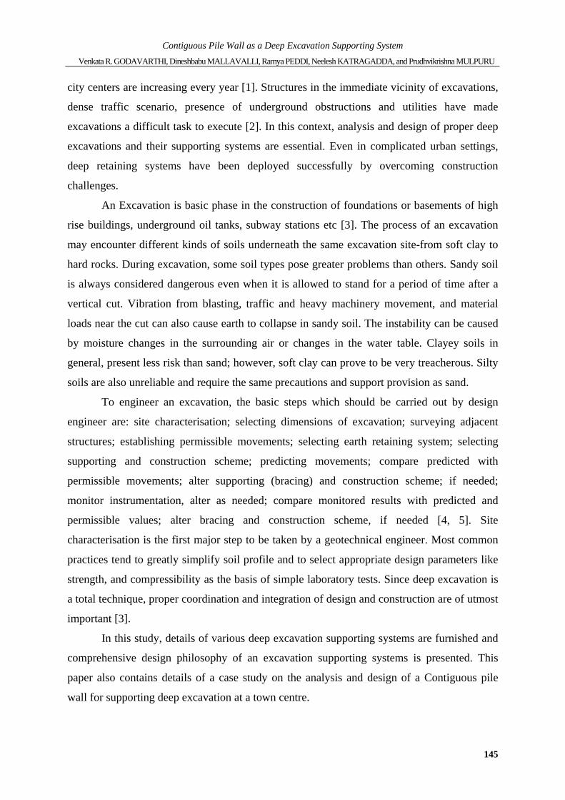
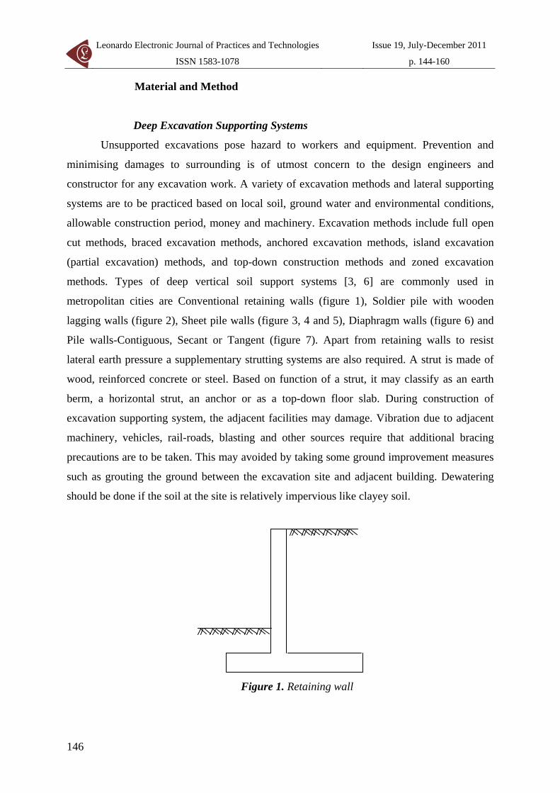
metropolitan cities are Conventional retaining walls (figure 1), Soldier pile with wooden
lagging walls (figure 2), Sheet pile walls (figure 3, 4 and 5), Diaphragm walls (figure 6) and
Pile walls-Contiguous, Secant or Tangent (figure 7). Apart from retaining walls to resist
lateral earth pressure a supplementary strutting systems are also required. A strut is made of
wood, reinforced concrete or steel. Based on function of a strut, it may classify as an earth
berm, a horizontal strut, an anchor or as a top-down floor slab. During construction of
excavation supporting system, the adjacent facilities may damage. Vibration due to adjacent
machinery, vehicles, rail-roads, blasting and other sources require that additional bracing
precautions are to be taken. This may avoided by taking some ground improvement measures
such as grouting the ground between the excavation site and adjacent building. Dewatering
should be done if the soil at the site is relatively impervious like clayey soil.
Figure 1. Retaining wall
Contiguous Pile Wall as a Deep Excavation Supporting System Venkata R. GODAVARTHI, Dineshbabu MALLAVALLI, Ramya PEDDI, Neelesh KATRAGADDA, and Prudhvikrishna MULPURU
147
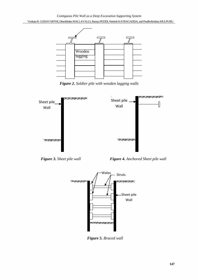
Figure 2. Soldier pile with wooden lagging walls
Sheet pile Wall
Figure 3. Sheet pile wall
Sheet pileWall
Figure 4. Anchored Sheet pile wall
Sheet pileWall
StrutsWales
Figure 5. Braced wall
Wooden lagging
Leonardo Electronic Journal of Practices and Technologies
ISSN 1583-1078
Issue 19, July-December 2011
p. 144-160
148
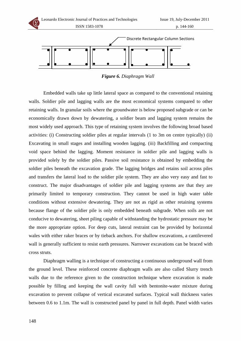
Discrete Rectangular Column Sections
Figure 6. Diaphragm Wall
Embedded walls take up little lateral space as compared to the conventional retaining
walls. Soldier pile and lagging walls are the most economical systems compared to other
retaining walls. In granular soils where the groundwater is below proposed subgrade or can be
economically drawn down by dewatering, a soldier beam and lagging system remains the
most widely used approach. This type of retaining system involves the following broad based
activities: (i) Constructing soldier piles at regular intervals (1 to 3m on centre typically) (ii)
Excavating in small stages and installing wooden lagging. (iii) Backfilling and compacting
void space behind the lagging. Moment resistance in soldier pile and lagging walls is
provided solely by the soldier piles. Passive soil resistance is obtained by embedding the
soldier piles beneath the excavation grade. The lagging bridges and retains soil across piles
and transfers the lateral load to the soldier pile system. They are also very easy and fast to
construct. The major disadvantages of soldier pile and lagging systems are that they are
primarily limited to temporary construction. They cannot be used in high water table
conditions without extensive dewatering. They are not as rigid as other retaining systems
because flange of the soldier pile is only embedded beneath subgrade. When soils are not
conducive to dewatering, sheet piling capable of withstanding the hydrostatic pressure may be
the more appropriate option. For deep cuts, lateral restraint can be provided by horizontal
wales with either raker braces or by tieback anchors. For shallow excavations, a cantilevered
wall is generally sufficient to resist earth pressures. Narrower excavations can be braced with
cross struts.
Diaphragm walling is a technique of constructing a continuous underground wall from
the ground level. These reinforced concrete diaphragm walls are also called Slurry trench
walls due to the reference given to the construction technique where excavation is made
possible by filling and keeping the wall cavity full with bentonite-water mixture during
excavation to prevent collapse of vertical excavated surfaces. Typical wall thickness varies
between 0.6 to 1.1m. The wall is constructed panel by panel in full depth. Panel width varies
Contiguous Pile Wall as a Deep Excavation Supporting System Venkata R. GODAVARTHI, Dineshbabu MALLAVALLI, Ramya PEDDI, Neelesh KATRAGADDA, and Prudhvikrishna MULPURU
149
from 2.5m to about 6m. Short widths of 2.5m are selected in less stable soils, under very high
surcharge or for very deep walls. It must be remembered that Diaphragm walls are
constructed as a series of alternating primary and secondary panels. Alternate primary panels
are constructed first which are restrained on either side by stop-end pipes. Before the
intermediate secondary panel excavation is taken up, the pipes are removed and the panel is
cast against two primary panels on either side to maintain continuity. The major disadvantage
of Diaphragm wall is it requires massive equipment, long construction period, and huge cost.
Piled Retaining Walls
In-situ pile retaining walls also called column piles are rows of concrete piles either
cast-in situ pile method or precast pile method. Merits of column piles are less noise or
vibration than produced by the installation of solider piles or sheet piles. Colum piles have
greater stiffness than soldier piles or steel sheet piles. They avoid excessive bulk excavation
and help to control ground movements. There are three distinct bored pile wall options in
current use: Contiguous wall, Secant wall and tangent wall.
Contiguous pile walls are constructed with small gaps between adjacent piles. The use
of low-cost augers and, more particularly, Contiguous Flight Auger (CFA) rigs to drill
successive unconnected piles provide an economical wall. Diameter and spacing of the piles
is decided based on soil type, ground water level and magnitude of design pressures. Large
spacing is avoided as it can result in caving of soil through gaps. CFA pile diameters range
from 300mm to 1000mm. CFA piles are considered more economical than diaphragm wall in
small to medium scale excavations due to reduction in cost and time of site operations.
Besides, no bentonite mud is needed for the excavation. Contiguous piles are suitable in
crowded urban areas, where traditional retaining methods would otherwise encroach the
adjoining properties, these piles restricts ground movements on the backfill side. The pile is
formed by first drilling into the ground with a CFA. Cement-sand grout or concrete is then
injected under pressure through the auger’s hollow stem as it is being withdrawn. The grout or
concrete pressure is maintained during the auger withdrawal so that it assists the extraction as
well as exerting a lateral pressure on the surrounding soils. On completion of this operation, a
reinforcing cage is placed into the fluid column of grout or concrete. When CFA pile
combined with capping beams/breasting beams can show savings in cost and time. Capping
beams at the top to help equitable pressure distributions in piles. Separate facing usually
Leonardo Electronic Journal of Practices and Technologies
ISSN 1583-1078
Issue 19, July-December 2011
p. 144-160
150
provided to improve looks. The range of soil conditions in which CFA piles can be used are
granular soils, cohesive soils, soft rocks. Soft clays, weak organic soils are unsuitable due to
wall bulging. Hard rocks are also not suitable. The Contiguous wall can only be used where
ground water is not a hazard or where grouting or jet grouting is used can be used to remedy
leakage between the piles. However, some acceptable amount of water can be collected at the
base and pumped out. The principal disadvantages of contiguous pile walls-the gaps between
piles and the resulting problems of lack of water proofness have been effectively overcome by
interlocking or secant piles.
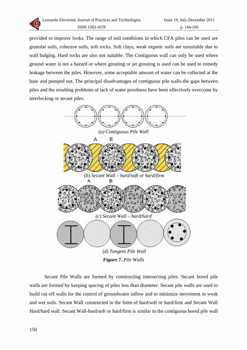
(a) Contiguous Pile Wall
(b) Secant Wall – hard/soft or hard/firm
(c) Secant Wall – hard/hard
(d) Tangent Pile Wall
Figure 7. Pile Walls
Secant Pile Walls are formed by constructing intersecting piles. Secant bored pile
walls are formed by keeping spacing of piles less than diameter. Secant pile walls are used to
build cut off walls for the control of groundwater inflow and to minimize movement in weak
and wet soils. Secant Wall constructed in the form of hard/soft or hard/firm and Secant Wall
Hard/hard wall. Secant Wall-hard/soft or hard/firm is similar to the contiguous bored pile wall
Contiguous Pile Wall as a Deep Excavation Supporting System Venkata R. GODAVARTHI, Dineshbabu MALLAVALLI, Ramya PEDDI, Neelesh KATRAGADDA, and Prudhvikrishna MULPURU
151
but the gap between piles is filled with an unreinforced cement/bentonite mix for the hard/soft
wall and weak concrete for the hard/firm wall. Construction is carried out by installing the
primary piles (A) and then the secondary piles (B) are formed in reinforced concrete, cutting
into the primary piles. Diameters can range from 500mm to 1200mm. Secant Wall Hard/hard
wall construction procedure is very similar to a hard/firm wall but in this case the primary
piles (A) are constructed in high strength concrete and may be reinforced. The Secondary
piles (B) are cut into the concrete primary piles (A) using heavy duty piling rigs fitted with
specially designed cutting heads. Tangent pile walls consist of a series of drilled shafts
located such that the adjacent shafts touch each other, hence the name tangent wall. Secant
pile walls are stiffer than tangent piles walls and are more effective in keeping ground water
out of the excavation.
Results and Discussion
Design Methodology Involving Excavation Retaining Systems
Stability of excavation is the major design criterion in order to avoid collapse of
excavations [3]. Stability analysis involves the distribution of earth pressures. Stability
analyses include push-in failure analysis, sand boiling analysis, and upheaval analysis. To
excavate in a sandy soil one should consider push-in and sand boiling. To excavate in a
clayey soil one should consider push-in and upheaval. In alternated layers of sand (or gravel)
and clay, push-in and upheaval should consider. The penetration depth of a retaining wall is
usually determined according to results of push-in failure because sand boiling is normally
not a main controlling factor. Goals of lowering the ground water level are to keep the
excavation bottom dry, to prevent leakage of water or sand, to avoid sand boiling or upheaval
failure, and to prevent the occurrence of floating basements.
Distribution of earth pressure influences stability, stress, and deformation analysis of
the deep excavation. For problems of excavation, considering that the active earth pressure is
usually the main force leading to the failure of the excavation supporting systems. The
passive earth pressure is usually the force resisting the failure. The pressure distribution shall
depend on the nature of backfill. An excavation will encounter various soil layers. Earth
pressure computed on the basis of Rankine’s earth pressure theory. If working with long term
behaviour, effective stress analysis should be applied to both cohesive and cohesionless soils
Leonardo Electronic Journal of Practices and Technologies
ISSN 1583-1078
Issue 19, July-December 2011
p. 144-160
152
and water pressure should be computed separately. Recharge wells may be required outside
the walls if drops in water level are not allowed. If there are compressible soils in the profile,
buildings and lifeline structures are expected to settle due to groundwater lowering.
Dewatering methods are applied in cases where there is need for control of water pressures
and/or flow [7].
There are two analysis methods for push-in failure: free-earth support method and
fixed earth support method [8, 9]. The free earth support method assumes that the embedment
of retaining wall is allowed to move a certain distance under the action of lateral earth
pressure. The fixed earth support method is to assume that embedment of the retaining wall
seems to be fixed at a point below the excavation surface. The embedded part may rotate
about fixed point. Thus, when the retaining wall is in the limiting state, the lateral earth
pressure around the fixed point on the two sides of the retaining wall does not necessarily
reach the active or passive pressures. If a cantilever wall is designed based on the free support
method, no fixed point is supposed to exist in the embedded part of the wall, as discussed
above. The external forces, only active and passive forces, on the retaining wall are not to
come to equilibrium. Therefore, the free earth support method is not applicable to cantilever
walls. A simplified analysis [10] of considering active force on one side and passive force on
the other side of excavation supporting system is used to simplify the calculation of necessary
depth of penetration or depth of embedment (DP). DP is found by applying moment
equilibrium about the bottom of the wall. The computed may be increased by 20 to 40%
beyond the point required by equilibrium or the effective horizontal pressure on the passive
side may be reduced by applying a factor of safety of 1.5 to 2.0 before the embedment depth
of pile is computed.
The upward flow may cause the effective stress at a point in soil to be zero, which
means that the soil is unable to bear any load, and the phenomenon is called sand boiling. The
hydraulic gradient when the effective stress equals zero is called critical hydraulic gradient
(icr), which can be expressed as follows:
w
1
cr = i γγ
(1)
The factor of safety against boiling can be estimated by Harza’s method, Terzaghi’s
method or simplified one-dimensional method. For excavations, a reasonable factor of safety
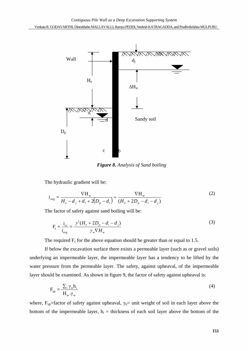
is around 1.5-2.0 [11]. The simplified one-dimensional method is presented in figure 8.
Contiguous Pile Wall as a Deep Excavation Supporting System Venkata R. GODAVARTHI, Dineshbabu MALLAVALLI, Ramya PEDDI, Neelesh KATRAGADDA, and Prudhvikrishna MULPURU
153
Figure 8. Analysis of Sand boiling
The hydraulic gradient will be:
( ) )2(H
2H
= i wwavg
jipeipije ddDHdDddH −−+∇
=−++−
∇
(2)
The factor of safety against sand boiling will be:
w
jipe
avg HddDH
i ∇−−+
w
1cr
s
)2( =i = F
γγ
(3)
The required Fs for the above equation should be greater than or equal to 1.5.
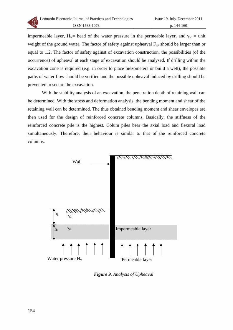
If below the excavation surface there exists a permeable layer (such as or gravel soils)
underlying an impermeable layer, the impermeable layer has a tendency to be lifted by the
water pressure from the permeable layer. The safety, against upheaval, of the impermeable
layer should be examined. As shown in figure 9, the factor of safety against upheaval is:
ww
itiiup γ.H
hγ = F ∑
(4)
where, Fup=factor of safety against upheaval, γti= unit weight of soil in each layer above the
bottom of the impermeable layer, hi = thickness of each soil layer above the bottom of the
Wall
He ∆Hw
a
di
Dp
b c
d
dj
Sandy soil
Leonardo Electronic Journal of Practices and Technologies
ISSN 1583-1078
Issue 19, July-December 2011
p. 144-160
154
impermeable layer, Hw= head of the water pressure in the permeable layer, and γw = unit
weight of the ground water. The factor of safety against upheaval Fup should be larger than or
equal to 1.2. The factor of safety against of excavation construction, the possibilities (of the
occurrence) of upheaval at each stage of excavation should be analysed. If drilling within the
excavation zone is required (e.g. in order to place piezometers or build a well), the possible
paths of water flow should be verified and the possible upheaval induced by drilling should be
prevented to secure the excavation.
With the stability analysis of an excavation, the penetration depth of retaining wall can
be determined. With the stress and deformation analysis, the bending moment and shear of the
retaining wall can be determined. The thus obtained bending moment and shear envelopes are
then used for the design of reinforced concrete columns. Basically, the stiffness of the
reinforced concrete pile is the highest. Colum piles bear the axial load and flexural load
simultaneously. Therefore, their behaviour is similar to that of the reinforced concrete
columns.
Figure 9. Analysis of Upheaval
Wall
h1
Impermeable layer h2
Permeable layer Water pressure Hw
γt1
γt2
Contiguous Pile Wall as a Deep Excavation Supporting System Venkata R. GODAVARTHI, Dineshbabu MALLAVALLI, Ramya PEDDI, Neelesh KATRAGADDA, and Prudhvikrishna MULPURU
155
Contiguous Pile Wall as Deep Excavation Supporting System at a
Commercial Complex in Vijayawada, Andhra Pradesh, India – Case History
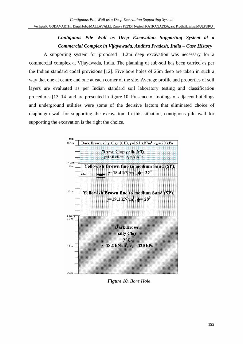
A supporting system for proposed 11.2m deep excavation was necessary for a
commercial complex at Vijayawada, India. The planning of sub-soil has been carried as per
the Indian standard codal provisions [12]. Five bore holes of 25m deep are taken in such a
way that one at centre and one at each corner of the site. Average profile and properties of soil
layers are evaluated as per Indian standard soil laboratory testing and classification
procedures [13, 14] and are presented in figure 10. Presence of footings of adjacent buildings
and underground utilities were some of the decisive factors that eliminated choice of
diaphragm wall for supporting the excavation. In this situation, contiguous pile wall for
supporting the excavation is the right the choice.
Figure 10. Bore Hole
Leonardo Electronic Journal of Practices and Technologies
ISSN 1583-1078
Issue 19, July-December 2011
p. 144-160
156
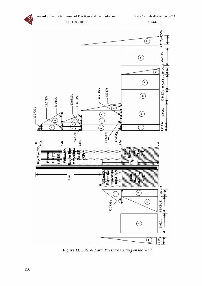
Figure 11. Lateral Earth Pressures acting on the Wall
Contiguous Pile Wall as a Deep Excavation Supporting System Venkata R. GODAVARTHI, Dineshbabu MALLAVALLI, Ramya PEDDI, Neelesh KATRAGADDA, and Prudhvikrishna MULPURU
157
Detailed lateral earth pressures acting on the wall are calculated and shown in figure
11. Stability analysis of the wall has been carried to evaluate the depth of penetration (DP) by
equating active pressure on right side of the wall to passive pressure on left side of the wall.
For the present case, DP is 5.64m. By applying factor of safety of 1.5 to coefficient of passive
earth pressure, DP is 7.79m. An actual penetration depth (DP) of 9.8m (=1.25×7.79m) is
adopted. The factor of safety against sand boiling is 5.16 obtained by using equation (3) with
consideration of sand layer throughout the penetration depth. This value is greater than 1.5.
Hence, wall is stable against sand boiling also.
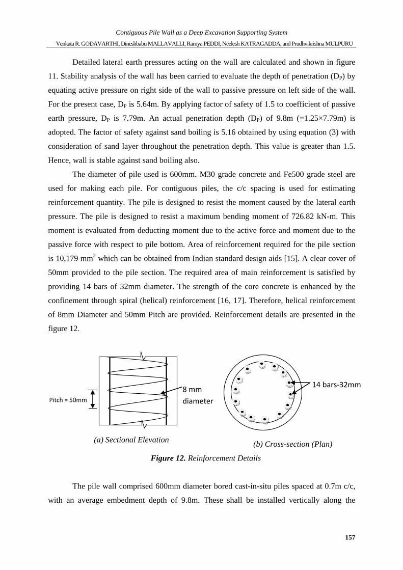
The diameter of pile used is 600mm. M30 grade concrete and Fe500 grade steel are
used for making each pile. For contiguous piles, the c/c spacing is used for estimating
reinforcement quantity. The pile is designed to resist the moment caused by the lateral earth
pressure. The pile is designed to resist a maximum bending moment of 726.82 kN-m. This
moment is evaluated from deducting moment due to the active force and moment due to the
passive force with respect to pile bottom. Area of reinforcement required for the pile section
is 10,179 mm2 which can be obtained from Indian standard design aids [15]. A clear cover of
50mm provided to the pile section. The required area of main reinforcement is satisfied by
providing 14 bars of 32mm diameter. The strength of the core concrete is enhanced by the
confinement through spiral (helical) reinforcement [16, 17]. Therefore, helical reinforcement
of 8mm Diameter and 50mm Pitch are provided. Reinforcement details are presented in the
figure 12.
(a) Sectional Elevation (b) Cross-section (Plan)
Figure 12. Reinforcement Details
The pile wall comprised 600mm diameter bored cast-in-situ piles spaced at 0.7m c/c,
with an average embedment depth of 9.8m. These shall be installed vertically along the
Pitch = 50mm
8 mm diameter
14 bars‐32mm
Leonardo Electronic Journal of Practices and Technologies
ISSN 1583-1078
Issue 19, July-December 2011
p. 144-160
158
proposed line of excavation. These piles were designed as cantilever retaining system without
provision of anchors. Capping beam of 1200 x 750mm size was cast along the alignment of
the pile which was designed to take care of differential changes in the earth pressures in the
adjacent piles. The peripheral length of excavation was 310m and 442 piles were involved in
the support work. Individual piles were constructed in the same way as a typical Bored Cast-
in-situ piles using temporary casings and bentonite slurry.
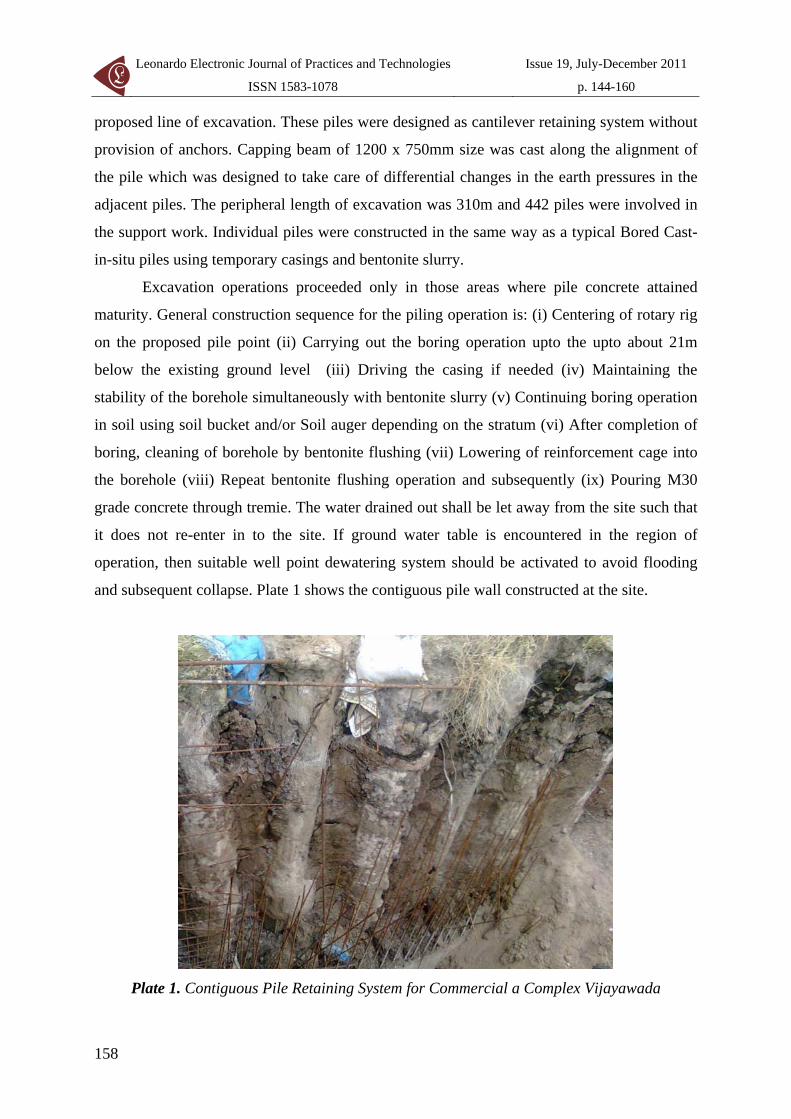
Excavation operations proceeded only in those areas where pile concrete attained
maturity. General construction sequence for the piling operation is: (i) Centering of rotary rig
on the proposed pile point (ii) Carrying out the boring operation upto the upto about 21m
below the existing ground level (iii) Driving the casing if needed (iv) Maintaining the
stability of the borehole simultaneously with bentonite slurry (v) Continuing boring operation
in soil using soil bucket and/or Soil auger depending on the stratum (vi) After completion of
boring, cleaning of borehole by bentonite flushing (vii) Lowering of reinforcement cage into
the borehole (viii) Repeat bentonite flushing operation and subsequently (ix) Pouring M30
grade concrete through tremie. The water drained out shall be let away from the site such that
it does not re-enter in to the site. If ground water table is encountered in the region of
operation, then suitable well point dewatering system should be activated to avoid flooding
and subsequent collapse. Plate 1 shows the contiguous pile wall constructed at the site.
Plate 1. Contiguous Pile Retaining System for Commercial a Complex Vijayawada
Contiguous Pile Wall as a Deep Excavation Supporting System Venkata R. GODAVARTHI, Dineshbabu MALLAVALLI, Ramya PEDDI, Neelesh KATRAGADDA, and Prudhvikrishna MULPURU
159
Conclusions
Lack of inadequate space at town centres goes for deep vertical excavations, which
require supports that are designed to consume minimum construction space. Various
excavation supporting systems are presented in this study. Contiguous pile wall is one good
choice of earth retention systems in the urban context. The detailed analysis and design of a
contiguous pile wall is explained by a Case study which uses contiguous pile wall as an
excavation supporting system at an urban centre.
Acknowledgements
Authors are thankful to Dr. P.V. Narasaiah, Director of SRK Institute of Technology,
Enikepadu, Vijayawada, Andhra Pradesh, India for his steady guidance and support.
References
1. Ergun M.U., Deep Excavations, Electronic Journal of Geotechnical Engineering,
Available at: www.ejge.com/Bouquet08/UfukErgun_ppr.pdf, 2008.
2. Manish Kumar, Deep support systems using diaphragm walls and contiguous piles,
National Seminar on Deep Excavation in Urban Environment, Mumbai, 2008, p. 1-18.
3. Chang-Yu Ou, Deep Excavation: Theory and Practice, Taylor and Francis Group,
London, UK, 2006.
4. Puller, M., Deep Excavations: A practical Manual, Thomas Telford, London, UK, 1998.
5. Moh Z.C., Chin C.T., Deep Excavation in Soft ground, Proceedings of ASIA
Construction: New Frontiers, Singapore, 1991.
6. BD 42/00, Design of Embedded Retaining Walls and Bridge Abutments, Department for
Regional Development, Scottish Executive Development Department, Northern Ireland.
7. Bureau of Indian Standards, Guidelines for Dewatering during Construction (IS: 9759),
Leonardo Electronic Journal of Practices and Technologies
ISSN 1583-1078
Issue 19, July-December 2011
p. 144-160
160
New Delhi, India, 1981.
8. Das B.M., Principles of Geotechnical Engineering, Cengage Learning, CT, USA, 2010.
9. Clayton C.R.I., Milititsky J., Woods R.I., Earth Pressure and Earth Retaining Structures,
Blackie Academic & Professional, London, 1993.
10. Teng W.C., Foundation Design, Prentice Hall, Englewood Cliffs, NJ, 1962.
11. NAVFAC, Foundations and Earth Structures, Design Manual 7.02, Department of the
Navy Naval Facilities Engineering Command, Alexandria, Virginia, 1982.
12. Bureau of Indian Standards, Code of practice for Subsurface Investigations for
foundations (IS: 1892), New Delhi, India, 1979.
13. Bureau of Indian Standards, Compendium of Indian Standards of Soil Engineering,
Laboratory Testing of soils for civil engineering (SP 36 Part 1), New Delhi, India.
14. Bureau of Indian Standards, Classification and Identification of soils for general
engineering purpose, IS 1498, New Delhi, India, 1970.
15. Bureau of Indian Standards, Design Aids for Reinforced concrete to IS: 456-1978 (SP 16),
New Delhi, India.
16. Dayaratnam P., Limit State Design of Reinforced Concrete structures, Oxford & IBH
Publishing Co. Pvt. Ltd., New Delhi, India, 2004.
17. Shah H.J., Reinforced Concrete Vol.1 (Elementary Reinforced Concrete), Charotar Book
House, Anand, Gujarat, India, 2005.