Embed Size (px)
Citation preview
Contents
������Camera Control Solutions
Next Page
Previous View
Vision 10LF
2
ContentsPrevious
PageFirst Page
Next Page
Previous View
Vision 10LFPAN AND TILT HEAD
3390
MAINTENANCE MANUALAND
ILLUSTRATED PARTS LIST
PUBLICATION PART No. 3390-9
ISSUE 3
Copyright Vinten Broadcast Limited 1999
All rights reserved throughout the world. No part of this document may be stored in a retrieval system, transmitted, copied or reproduced in any way including, but not limited to, photocopy, photograph, magnetic or
other record without the prior agreement and permission in writing of Vinten Broadcast Limited.
Vinten, Vision and Quickfit are registered trademarks of Vinten Broadcast Limited.
3
ContentsPrevious
PageFirst Page
Next Page
Previous View
Foreword
This manual provides full and detailed maintenance and spare parts information for the Vinten® Vision® 10LF pan and tilt head.
It is recommended that this manual is read carefully and the illustrations studied prior to operating or servicing the pan and tilt head. Attention to the details contained herein will ensure that the pan and tilt head will operate efficiently with the minimum of attention over a long service life. Particular attention must be paid to cleaning, especially after use in adverse conditions.
To order spare parts or to obtain further information, application should be made to Vinten Broadcast Limited or to your local distributor.
WARNING!: Read the Safety Section on page 8 before using this pan and tilt head or attempting any adjustment or repair.
NOTE: Information contained in this document is subject to change.Vinten Broadcast Ltd reserves the right, without notice, to make changes in equipment design or performance as progress in engineering, manufacturing or technology may warrant.

4
ContentsPrevious
PageFirst Page
Next Page
Previous View
Notes to readers
This is the on-line version of ‘Vision 10LF Pan and Tilt Head Maintenance Manual’ (3390-9). Readers should be aware that the pagination differs between on-line and printed versions.
Navigation
Clicking the mouse on any blue text will move you around the document. For example, if you click on one of the blue call-outs on an exploded drawing, you will be taken to the appropriate line in the relevant parts list.
Clicking here will take you to the Contents Page.
Clicking here will take you to the first page.
Clicking here will take you to the previous page.
Clicking here will take you to the next page.
Click here to go back to the previous view.
Alternatively, you may use the Acrobat Reader navigation buttons.
Contents

5
Contents
Page
Previous Page
First Page
Next Page
Previous View
Foreword . . . . . . . . . . . . . . . . . . . . . . . . . . . . . . . . . . . . . . . . . . . . . . . . . . . . . . . . . . . . . . . . . . . . . . . . . . . . . 3
Notes to readers . . . . . . . . . . . . . . . . . . . . . . . . . . . . . . . . . . . . . . . . . . . . . . . . . . . . . . . . . . . . . . . . . . . . . . . 4
Safety - Read This First! . . . . . . . . . . . . . . . . . . . . . . . . . . . . . . . . . . . . . . . . . . . . . . . . . . . . . . . . . . . . . . . . . 8
Technical Specification . . . . . . . . . . . . . . . . . . . . . . . . . . . . . . . . . . . . . . . . . . . . . . . . . . . . . . . . . . . . . . . . 10
Design Improvements. . . . . . . . . . . . . . . . . . . . . . . . . . . . . . . . . . . . . . . . . . . . . . . . . . . . . . . . . . . . . . . . . . 11
Section 1 - Introduction and Description
Introduction . . . . . . . . . . . . . . . . . . . . . . . . . . . . . . . . . . . . . . . . . . . . . . . . . . . . . . . . . . . . . . . . . . . . . . . 12
Description . . . . . . . . . . . . . . . . . . . . . . . . . . . . . . . . . . . . . . . . . . . . . . . . . . . . . . . . . . . . . . . . . . . . . . . . 12
Section 2 - Installation and Operation
General . . . . . . . . . . . . . . . . . . . . . . . . . . . . . . . . . . . . . . . . . . . . . . . . . . . . . . . . . . . . . . . . . . . . . . . . . . 14
Installing the head on a tripod . . . . . . . . . . . . . . . . . . . . . . . . . . . . . . . . . . . . . . . . . . . . . . . . . . . . . . . . . 14
Mounting the camera . . . . . . . . . . . . . . . . . . . . . . . . . . . . . . . . . . . . . . . . . . . . . . . . . . . . . . . . . . . . . . . . 14
Mounting the camera (optional Quickfit adaptor) . . . . . . . . . . . . . . . . . . . . . . . . . . . . . . . . . . . . . . . . . . . 15
Balancing the head . . . . . . . . . . . . . . . . . . . . . . . . . . . . . . . . . . . . . . . . . . . . . . . . . . . . . . . . . . . . . . . . . 16
Pan and tilt brakes . . . . . . . . . . . . . . . . . . . . . . . . . . . . . . . . . . . . . . . . . . . . . . . . . . . . . . . . . . . . . . . . . . 17
Pan and tilt drag. . . . . . . . . . . . . . . . . . . . . . . . . . . . . . . . . . . . . . . . . . . . . . . . . . . . . . . . . . . . . . . . . . . . 17
Section 3 - Tools and Materials
General . . . . . . . . . . . . . . . . . . . . . . . . . . . . . . . . . . . . . . . . . . . . . . . . . . . . . . . . . . . . . . . . . . . . . . . . . . 18
Special tools. . . . . . . . . . . . . . . . . . . . . . . . . . . . . . . . . . . . . . . . . . . . . . . . . . . . . . . . . . . . . . . . . . . . . . . 18
Consumable materials. . . . . . . . . . . . . . . . . . . . . . . . . . . . . . . . . . . . . . . . . . . . . . . . . . . . . . . . . . . . . . . 18
Section 4 - Servicing
General . . . . . . . . . . . . . . . . . . . . . . . . . . . . . . . . . . . . . . . . . . . . . . . . . . . . . . . . . . . . . . . . . . . . . . . . . . 20
Cleaning. . . . . . . . . . . . . . . . . . . . . . . . . . . . . . . . . . . . . . . . . . . . . . . . . . . . . . . . . . . . . . . . . . . . . . . . . . 20
Lubrication . . . . . . . . . . . . . . . . . . . . . . . . . . . . . . . . . . . . . . . . . . . . . . . . . . . . . . . . . . . . . . . . . . . . . . . . 20
Adjustments
Drag control knob adjustment . . . . . . . . . . . . . . . . . . . . . . . . . . . . . . . . . . . . . . . . . . . . . . . . . . . . . . . 21
Brake knob adjustment . . . . . . . . . . . . . . . . . . . . . . . . . . . . . . . . . . . . . . . . . . . . . . . . . . . . . . . . . . . . 22

6
Contents (Cont) Page
Previous Page
First Page
Next Page
Previous View
Section 5 - Repair
General . . . . . . . . . . . . . . . . . . . . . . . . . . . . . . . . . . . . . . . . . . . . . . . . . . . . . . . . . . . . . . . . . . . . . . . . . . 24
Disassembly. . . . . . . . . . . . . . . . . . . . . . . . . . . . . . . . . . . . . . . . . . . . . . . . . . . . . . . . . . . . . . . . . . . . . . . 25
Platform. . . . . . . . . . . . . . . . . . . . . . . . . . . . . . . . . . . . . . . . . . . . . . . . . . . . . . . . . . . . . . . . . . . . . . . . 25
Tilt mechanism . . . . . . . . . . . . . . . . . . . . . . . . . . . . . . . . . . . . . . . . . . . . . . . . . . . . . . . . . . . . . . . . . . 25
Balance mechanism . . . . . . . . . . . . . . . . . . . . . . . . . . . . . . . . . . . . . . . . . . . . . . . . . . . . . . . . . . . . . . 27
Pan mechanism . . . . . . . . . . . . . . . . . . . . . . . . . . . . . . . . . . . . . . . . . . . . . . . . . . . . . . . . . . . . . . . . . 27
Mechanism housing assembly . . . . . . . . . . . . . . . . . . . . . . . . . . . . . . . . . . . . . . . . . . . . . . . . . . . . . . 28
Assembly . . . . . . . . . . . . . . . . . . . . . . . . . . . . . . . . . . . . . . . . . . . . . . . . . . . . . . . . . . . . . . . . . . . . . . . . . 28
Mechanism housing assembly . . . . . . . . . . . . . . . . . . . . . . . . . . . . . . . . . . . . . . . . . . . . . . . . . . . . . . 28
Pan mechanism . . . . . . . . . . . . . . . . . . . . . . . . . . . . . . . . . . . . . . . . . . . . . . . . . . . . . . . . . . . . . . . . . 29
Tilt mechanism . . . . . . . . . . . . . . . . . . . . . . . . . . . . . . . . . . . . . . . . . . . . . . . . . . . . . . . . . . . . . . . . . . 30
Balance mechanism . . . . . . . . . . . . . . . . . . . . . . . . . . . . . . . . . . . . . . . . . . . . . . . . . . . . . . . . . . . . . . 32
Platform. . . . . . . . . . . . . . . . . . . . . . . . . . . . . . . . . . . . . . . . . . . . . . . . . . . . . . . . . . . . . . . . . . . . . . . . 33
Final assembly . . . . . . . . . . . . . . . . . . . . . . . . . . . . . . . . . . . . . . . . . . . . . . . . . . . . . . . . . . . . . . . . . . 34
Section 6 - Illustrated Parts List
Introduction . . . . . . . . . . . . . . . . . . . . . . . . . . . . . . . . . . . . . . . . . . . . . . . . . . . . . . . . . . . . . . . . . . . . . 35
Ordering spare parts. . . . . . . . . . . . . . . . . . . . . . . . . . . . . . . . . . . . . . . . . . . . . . . . . . . . . . . . . . . . . . 35
Main assembly part numbers . . . . . . . . . . . . . . . . . . . . . . . . . . . . . . . . . . . . . . . . . . . . . . . . . . . . . . . 36
7
ContentsPrevious
PageFirst Page
Next Page
Previous View
Illustrations Page
Fig 1.1 Vision 10LF Pan and Tilt Head . . . . . . . . . . . . . . . . . . . . . . . . . . . . . . . . . . . . . . . . . . . . . . . . . . . . . 13
Fig 2.1 Mounting the Camera (Optional Quickfit Adaptor) . . . . . . . . . . . . . . . . . . . . . . . . . . . . . . . . . . . . . . 15
Fig 2.2 Balance Graph . . . . . . . . . . . . . . . . . . . . . . . . . . . . . . . . . . . . . . . . . . . . . . . . . . . . . . . . . . . . . . . . . 16
Fig 4.1 Drag Control Knob Adjustment . . . . . . . . . . . . . . . . . . . . . . . . . . . . . . . . . . . . . . . . . . . . . . . . . . . . . 21
Fig 4.2 Brake Knob Adjustment . . . . . . . . . . . . . . . . . . . . . . . . . . . . . . . . . . . . . . . . . . . . . . . . . . . . . . . . . . 23
Fig 6.1 Vision 10LF Pan and Tilt Head . . . . . . . . . . . . . . . . . . . . . . . . . . . . . . . . . . . . . . . . . . . . . . . . . . . . . 37
Fig 6.2 Vision 10LF Pan and Tilt Head - Mechanism Housing Assembly . . . . . . . . . . . . . . . . . . . . . . . . . . . 39
Fig 6.3 Vision 10LF Pan and Tilt Head - Platform and Balance Mechanism. . . . . . . . . . . . . . . . . . . . . . . . . 41
Fig 6.4 Vision 10LF Pan and Tilt Head - Tilt Mechanism . . . . . . . . . . . . . . . . . . . . . . . . . . . . . . . . . . . . . . . 44
Fig 6.5 Vision 10LF Pan and Tilt Head - Pan Mechanism. . . . . . . . . . . . . . . . . . . . . . . . . . . . . . . . . . . . . . . 47
Fig 6.6 Vision 10LF Pan and Tilt Head - Pan Bar . . . . . . . . . . . . . . . . . . . . . . . . . . . . . . . . . . . . . . . . . . . . . 50
Associated Publication
Vision LF Series Pan and Tilt Heads Operators Guide - Publication Part No. 3390-8

8
ContentsPrevious
PageFirst Page
Next Page
Previous View
Safety - Read This First!
Warning symbols in this maintenance manual
Where there is a risk of personal injury, injury to others, or damage to the pan and tilt head or associated equipment, comments appear, highlighted by the word WARNING! and supported by the warning triangle symbol.
Critical data
Mass
Mass 3 kg (6.6 lb)
Load
Typical payload 13 kg (28 lb)

9
ContentsPrevious
PageFirst Page
Next Page
Previous View
Abbreviations
The following abbreviations are used in this publication:
ac alternating current
A Amps
AF across flats
A/R as required
ASME American Society of Mech Engineers
assy assembly
BS British Standard
BA British Association thread
BSF British Standard Fine thread
BSP British Standard Parallel Pipe thread
BSW British Standard Whitworth thread
btn button
chs cheese
C of G centre of gravity
comp compression
csk countersunk
cu cubic
c/w complete with
dc direct current
dia diameter
ft foot
hd head
hex hexagon
Hz Hertz (frequency)
IC integrated circuit
ID inside diameter
in. inch
kg kilogram
lb pound (weight)
LF Lubricated Friction
LH left hand
MISO metric thread
m metre
mm millimetre
N Newton
NPT National Pipe thread
NI not illustrated
No. number
OD outside diameter
PCB printed circuit board
PCD pitch circle diameter
pozi Pozidriv
psi pounds per square inch
pt point
PTFE Polytetrafluoroethylene
PVC Polyvinyl chloride
RH right hand
sect section
skt socket
SWG standard wire gauge
thk thick
UNC Unified Coarse thread
UNF Unified Fine thread
V Volts
W Watts
10
ContentsPrevious
PageFirst Page
Next Page
Previous View
Technical Specification
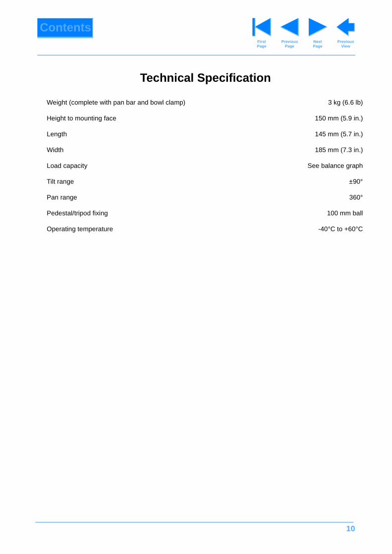
Weight (complete with pan bar and bowl clamp) 3 kg (6.6 lb)
Height to mounting face 150 mm (5.9 in.)
Length 145 mm (5.7 in.)
Width 185 mm (7.3 in.)
Load capacity See balance graph
Tilt range ±90°
Pan range 360°
Pedestal/tripod fixing 100 mm ball
Operating temperature -40°C to +60°C

11
ContentsPrevious
PageFirst Page
Next Page
Previous View
Design Improvements
DETAILSSERIAL No.
INFORMATION
Improvements to pan and tilt drag unit seals 1197
Improvements to brake shafts 3282
Bowl clamp - improved clamping efficiency 5330
12
ContentsPrevious
PageFirst Page
Next Page
Previous View
Section 1
Introduction and Description
Contents Para
Introduction . . . . . . . . . . . . . . . . . . . . . . . . . . . . . . . . . . . . . . . . . . . . . . . . . . . . . . . . . . . . . . . . . . . . . . . . . . 1
Description . . . . . . . . . . . . . . . . . . . . . . . . . . . . . . . . . . . . . . . . . . . . . . . . . . . . . . . . . . . . . . . . . . . . . . . . . . . 3
Introduction
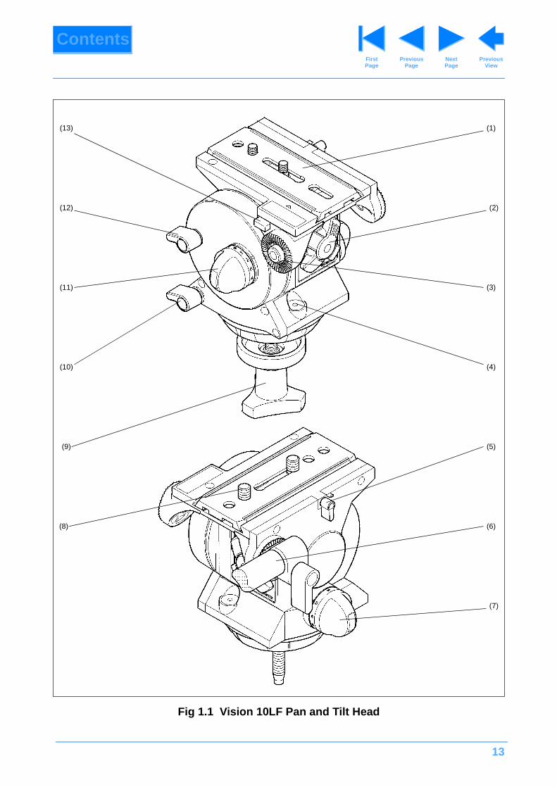
1 The Vision 10LF pan and tilt head is part of a range designed for broadcast professional, corporate and educational use. It is largely constructed in aluminium alloy to produce a robust, lightweight unit. The unique counterbalance system enables a wide variety of camera/lens combinations to be maintained in perfect balance over the range of tilt movements. A maximum tilt angle of ±90° is available at intermediate loadings, whilst at higher loadings the range of tilt motion is progressively reduced to ±40°. A graph is provided in Section 2 which illustrates the relationship between load and centre-of-gravity (C of G) and may be used to ascertain the suitability of the head for any given combination of camera, lens and accessories.
2 Drag is provided by the Vinten lubricated friction (LF) system which allows wide variation of the drag setting on both pan and tilt axes to suit operator preference, and permits “whip” movements to be executed, irrespective of drag setting. Pan and tilt movements are each provided with a brake.
Description
3 The Vision 10LF pan and tilt head embodies a spring counterbalance mechanism, lubricated friction drag assemblies and brakes on the pan and tilt mechanisms and a camera mounting plate.
4 The balance system is easily adjusted by a knob (1) on the rear of the head. Maximum and minimum payloads that can be balanced, and tilt ranges, are dependent on the weight of the camera and accessories and on the centre-of-gravity (C of G) height. The control compensates for differing platform loads by varying the compressive force on the counterbalance spring.
5 Both the pan and tilt mechanisms incorporate the Vinten LF system to ensure smooth movement of the camera about these axes and are fitted with control knobs (7)(11) to adjust the drag setting. The whip-pan facility is unaffected by the pan drag setting. Both drag knobs are provided with scales.
6 Friction brakes on each axis allow the head to be locked at any chosen position. The operating levers for both brakes (10)(12) are fitted at the left-hand side of the head.
7 Pan bar mounting points (3) are located at the rear of the head, on either side of the camera mounting platform. A pan bar (6) is supplied and is attached using a pan bar clamp, with angular adjustment available on the mount serrations. A second pan bar may be fitted.
8 The camera is attached to the head by means of a slide plate (1) or by using the optional Quickfit adaptor. A clamp (5) is provided to hold the slide plate in position and a lock (13) prevents its inadvertent removal from the head.
9 A ball base and clamp (9) for mounting on a 100 mm bowl is provided. Adaptors are available which permit installation on other mounts.
13
ContentsPrevious
PageFirst Page
Next Page
Previous View
Fig 1.1 Vision 10LF Pan and Tilt Head
(1)
(3)
(2)
(6)
(4)
(8)
(5)
(7)
(9)
(10)
(11)
(13)
(12)
14
ContentsPrevious
PageFirst Page
Next Page
Previous View
Section 2
Installation and Operation
Contents Para
General. . . . . . . . . . . . . . . . . . . . . . . . . . . . . . . . . . . . . . . . . . . . . . . . . . . . . . . . . . . . . . . . . . . . . . . . . . . . . . 1
Installing the head on a tripod . . . . . . . . . . . . . . . . . . . . . . . . . . . . . . . . . . . . . . . . . . . . . . . . . . . . . . . . . . . 2
Mounting the camera . . . . . . . . . . . . . . . . . . . . . . . . . . . . . . . . . . . . . . . . . . . . . . . . . . . . . . . . . . . . . . . . . . 5
Mounting the camera (optional Quickfit adaptor) . . . . . . . . . . . . . . . . . . . . . . . . . . . . . . . . . . . . . . . . . . . 9
Balancing the head . . . . . . . . . . . . . . . . . . . . . . . . . . . . . . . . . . . . . . . . . . . . . . . . . . . . . . . . . . . . . . . . . . . 10
Pan and tilt brakes . . . . . . . . . . . . . . . . . . . . . . . . . . . . . . . . . . . . . . . . . . . . . . . . . . . . . . . . . . . . . . . . . . . 13
Pan and tilt drag . . . . . . . . . . . . . . . . . . . . . . . . . . . . . . . . . . . . . . . . . . . . . . . . . . . . . . . . . . . . . . . . . . . . . 15
General
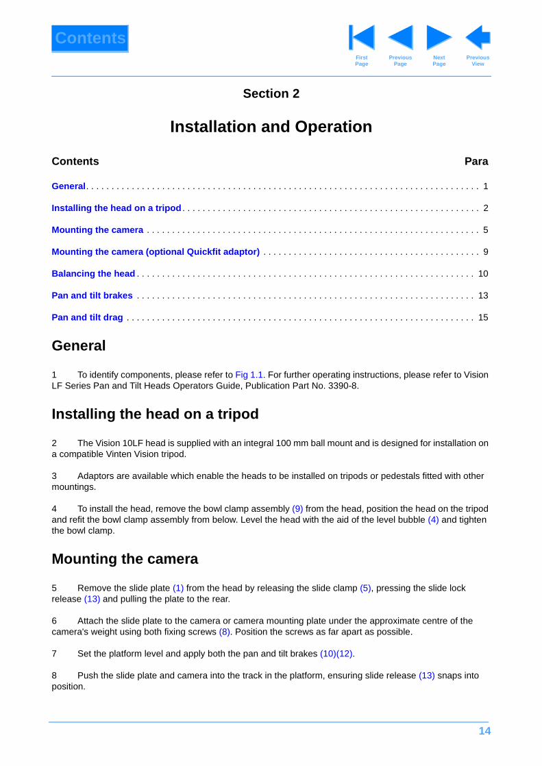
1 To identify components, please refer to Fig 1.1. For further operating instructions, please refer to Vision LF Series Pan and Tilt Heads Operators Guide, Publication Part No. 3390-8.
Installing the head on a tripod
2 The Vision 10LF head is supplied with an integral 100 mm ball mount and is designed for installation on a compatible Vinten Vision tripod.
3 Adaptors are available which enable the heads to be installed on tripods or pedestals fitted with other mountings.
4 To install the head, remove the bowl clamp assembly (9) from the head, position the head on the tripod and refit the bowl clamp assembly from below. Level the head with the aid of the level bubble (4) and tighten the bowl clamp.
Mounting the camera
5 Remove the slide plate (1) from the head by releasing the slide clamp (5), pressing the slide lock release (13) and pulling the plate to the rear.
6 Attach the slide plate to the camera or camera mounting plate under the approximate centre of the camera's weight using both fixing screws (8). Position the screws as far apart as possible.
7 Set the platform level and apply both the pan and tilt brakes (10)(12).
8 Push the slide plate and camera into the track in the platform, ensuring slide release (13) snaps into position.
15
ContentsPrevious
PageFirst Page
Next Page
Previous View
Mounting the camera (optional Quickfit adaptor)
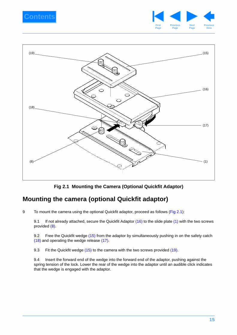
9 To mount the camera using the optional Quickfit adaptor, proceed as follows (Fig 2.1):
9.1 If not already attached, secure the Quickfit Adaptor (16) to the slide plate (1) with the two screws provided (8).
9.2 Free the Quickfit wedge (15) from the adaptor by simultaneously pushing in on the safety catch (18) and operating the wedge release (17).
9.3 Fit the Quickfit wedge (15) to the camera with the two screws provided (19).
9.4 Insert the forward end of the wedge into the forward end of the adaptor, pushing against the spring tension of the lock. Lower the rear of the wedge into the adaptor until an audible click indicates that the wedge is engaged with the adaptor.
Fig 2.1 Mounting the Camera (Optional Quickfit Adaptor)
(15)
(16)
(17)
(1)(8)
(18)
(19)
16
ContentsPrevious
PageFirst Page
Next Page
Previous View
Balancing the head
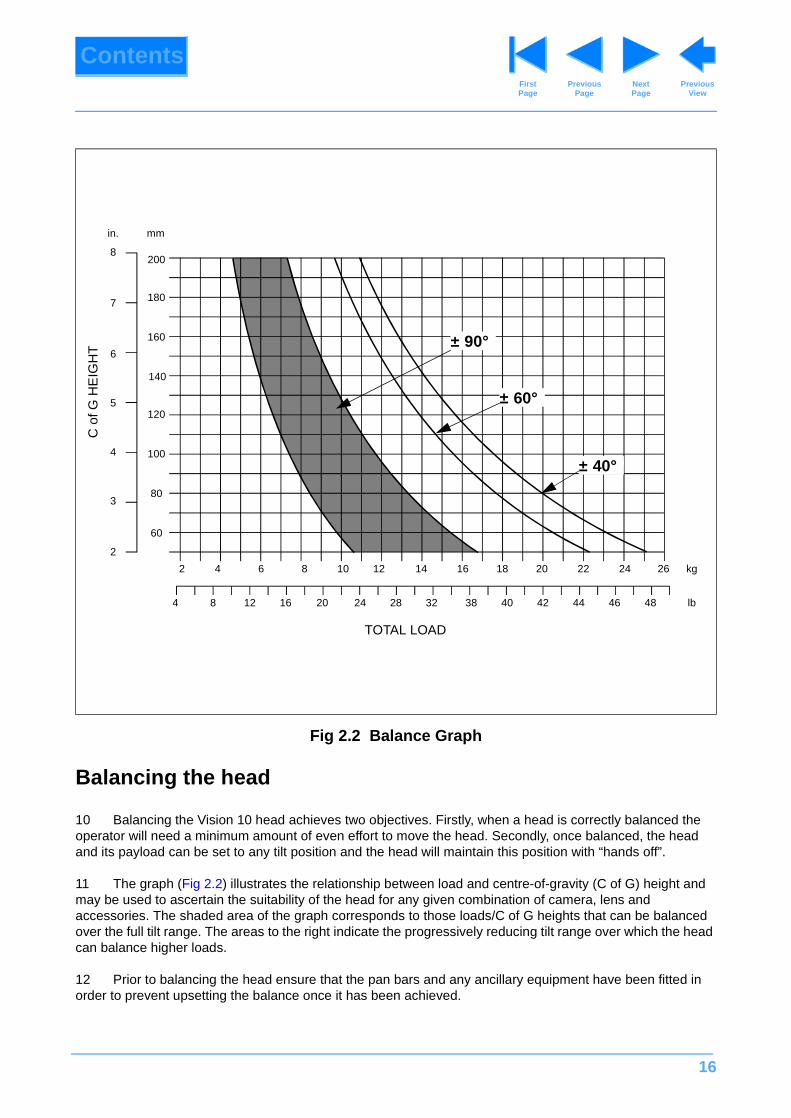
10 Balancing the Vision 10 head achieves two objectives. Firstly, when a head is correctly balanced the operator will need a minimum amount of even effort to move the head. Secondly, once balanced, the head and its payload can be set to any tilt position and the head will maintain this position with “hands off”.
11 The graph (Fig 2.2) illustrates the relationship between load and centre-of-gravity (C of G) height and may be used to ascertain the suitability of the head for any given combination of camera, lens and accessories. The shaded area of the graph corresponds to those loads/C of G heights that can be balanced over the full tilt range. The areas to the right indicate the progressively reducing tilt range over which the head can balance higher loads.
12 Prior to balancing the head ensure that the pan bars and any ancillary equipment have been fitted in order to prevent upsetting the balance once it has been achieved.
Fig 2.2 Balance Graph
200
180
160
140
8
7
6
5120
1004
80
60
3
2
2 4 6 8 10 12 14 16 18 20 22 24 26
484644424038322824201284
in. mm
kg
lb
± 90°
± 60°
± 40°
TOTAL LOAD
C o
f G H
EIG
HT
16
17
ContentsPrevious
PageFirst Page
Next Page
Previous View
12.1 Release the tilt brake (12). Turn the balance knob (2) counter-clockwise until the head falls away from horizontal under the weight of the camera.
12.2 Release the slide clamp (5) and slide the camera backwards or forward until it balances horizontally. Apply the slide clamp (5).
12.3 Turn the balance knob (2) clockwise until the camera does not fall away when the head is tilted and released.
12.4 Repeat Para 12.2 and Para 12.3 until perfect balance is achieved, when the camera will remain set at any angle from +90° to –90° without falling away or springing back. Re-apply the tilt brake (12).
Pan and tilt brakes
13 Friction brakes on each axis allow the head to be locked at any chosen position. The operating levers for the pan brake (10) and tilt brake (12) are fitted at the left-hand side of the head.
14 To apply the brake, turn the lever fully clockwise. To release the brake, turn the lever fully counter-clockwise.
Pan and tilt drag
15 Both the pan and tilt mechanisms incorporate the Vinten liquid friction (LF) system to ensure smooth movement of the camera about these axes. and are fitted with control knobs to adjust the drag setting.
16 The tilt drag adjustment knob (11) is on the left-hand side of the head, the pan drag knob (7) is on the right -hand side. Both drag knobs are provided with scales, graduated from 0 to 9. The whip-pan facility is unaffected by the pan drag setting.
17 To increase drag, turn the knob clockwise, towards a higher graduation. To decrease drag, turn the knob anti-clockwise, towards a lower graduation.
NOTE: Maximum tilt angle is less than 90° for heavy payloads with high C of G - see balance graph.
18
ContentsPrevious
PageFirst Page
Next Page
Previous View
Section 3
Tools and Materials
General
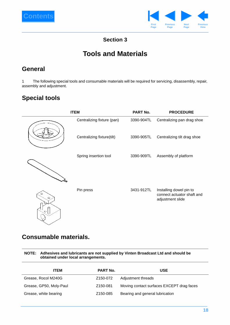
1 The following special tools and consumable materials will be required for servicing, disassembly, repair, assembly and adjustment.
Special tools
Consumable materials.
ITEM PART No. PROCEDURE
Centralizing fixture (pan) 3390-904TL Centralizing pan drag shoe
Centralizing fixture(tilt) 3390-905TL Centralizing tilt drag shoe
Spring insertion tool 3390-909TL Assembly of platform
Pin press 3431-912TL Installing dowel pin to connect actuator shaft and adjustment slide
NOTE: Adhesives and lubricants are not supplied by Vinten Broadcast Ltd and should be obtained under local arrangements.
ITEM PART No. USE
Grease, Rocol M240G Z150-072 Adjustment threads
Grease, GP50, Moly-Paul Z150-081 Moving contact surfaces EXCEPT drag faces
Grease, white bearing Z150-085 Bearing and general lubrication

19
ContentsPrevious
PageFirst Page
Next Page
Previous View
Grease, Chesterton Z150-105 Actuator shaft
Grease, Castrol LM Z150-123 Thrust races
Vinten Fluid No. 3 3051-25 Drag housings
Loctite 221 Z002-026 Screw locking
Loctite 222E* Z002-075 Screw locking
Loctite 241 Z002-022 Screw locking
Loctite 270 Z002-034 Screw locking
Loctite 380* Z002-078 Adhesive
Loctite 406 Z002-086 Adhesive
Loctite 415 Z002-062 Adhesive
Loctite 495* Z002-059 Spring cap buffer
Loctite 601* Z002-020 Adhesive
Loctite 638* Z002-058 Adhesive
Loctite 641* Z002-074 Bearing retainer
Loctite primer N Z002-011 Primer for Loctite 222E
Loctite primer T Z002-019 Primer for Loctite 221
Silcoset 153* Z002-036 Brake knob caps
ITEM PART No. USE
20
ContentsPrevious
PageFirst Page
Next Page
Previous View
Section 4
Servicing
Contents Para
General. . . . . . . . . . . . . . . . . . . . . . . . . . . . . . . . . . . . . . . . . . . . . . . . . . . . . . . . . . . . . . . . . . . . . . . . . . . . . . 1
Cleaning . . . . . . . . . . . . . . . . . . . . . . . . . . . . . . . . . . . . . . . . . . . . . . . . . . . . . . . . . . . . . . . . . . . . . . . . . . . . . 2
Lubrication. . . . . . . . . . . . . . . . . . . . . . . . . . . . . . . . . . . . . . . . . . . . . . . . . . . . . . . . . . . . . . . . . . . . . . . . . . . 4
Adjustments
Drag control knob adjustment
Normal conditions . . . . . . . . . . . . . . . . . . . . . . . . . . . . . . . . . . . . . . . . . . . . . . . . . . . . . . . . . . . . . . . . . 7
Operation in low ambient temperatures . . . . . . . . . . . . . . . . . . . . . . . . . . . . . . . . . . . . . . . . . . . . . . . . 8
Brake knob adjustment . . . . . . . . . . . . . . . . . . . . . . . . . . . . . . . . . . . . . . . . . . . . . . . . . . . . . . . . . . . . . . 10
General
1 The Vision 10LF head requires a minimum of periodic servicing. Its rotational and drag mechanisms are totally enclosed to prevent the ingress of dirt or foreign bodies. If the head becomes faulty reference should be made to Section 5 of this manual, or the unit may be returned to Vinten Broadcast Limited or your local distributor for overhaul.
Cleaning
2 During indoor use, the only cleaning required should be a regular wipe over with a lint-free cloth. Dirt accumulated during storage may be removed using a semi-stiff brush. Particular attention should be paid to the levelling ball and mounting face of the head and to the space between the tilting assembly and the base.
3 The Vision 10LF head is weatherproof. However, use out-of-doors under adverse conditions will require special attention. Salt spray should be washed off with fresh water at the earliest opportunity. Sand and dirt acts as an abrasive and should be removed using a semi-stiff brush or vacuum cleaner.
Lubrication
4 The bearings in the pan and tilt head are packed with grease. Under normal operating conditions they will only require re-greasing if there is any harshness or stiffness in movement. Refer to Section 5 to dismantle the head for re-greasing.
NOTE: Use only detergent-based cleaners. DO NOT use solvent- or oil-based cleaners, abrasives or wire brushes to remove accumulations of dirt, as these damage the protective surfaces.
21
ContentsPrevious
PageFirst Page
Next Page
Previous View
5 To check the bearings, turn the balance control as far as possible counter-clockwise, turn the pan and tilt drag controls fully counter-clockwise and release the brakes. At these settings both pan and tilt axes should move smoothly and without perceptible drag.
Adjustments
Drag control knob adjustment
Normal conditions
6 The pan and tilt drag controls on the Vision 10LF head operate by expanding a drag shoe with an actuator. Bedding-in occurs between the actuator and the shoe, which requires resetting of the drag control knob. This simple adjustment should be performed after one month's service and at six monthly intervals thereafter.
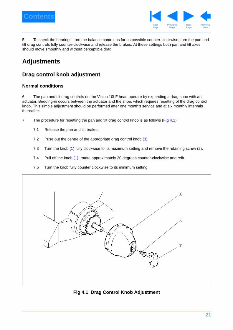
7 The procedure for resetting the pan and tilt drag control knob is as follows (Fig 4.1):
7.1 Release the pan and tilt brakes.
7.2 Prise out the centre of the appropriate drag control knob (3).
7.3 Turn the knob (1) fully clockwise to its maximum setting and remove the retaining screw (2).
7.4 Pull off the knob (1), rotate approximately 20 degrees counter-clockwise and refit.
7.5 Turn the knob fully counter clockwise to its minimum setting.
Fig 4.1 Drag Control Knob Adjustment
(1)
(2)
(3)
22
ContentsPrevious
PageFirst Page
Next Page
Previous View
7.6 Turn knob clockwise and ensure that drag begins to be felt at a setting between 1 and 1.5 on the drag knob. Repeat Para 7.4 until this can be achieved.
7.7 Secure knob with screw (2) and refit knob centre (3).
Operation in low ambient temperatures
8 Use of the Vision 10LF head in ambient temperatures below -20° C may result in excessive drag in the pan and tilt axes. Should this problem arise it can be overcome by adjustment of each drag setting knob as follows (Fig 4.1):
8.1 Release the pan and tilt brakes.
8.2 Prise out the centre of the appropriate drag control knob (3).
8.3 Turn the knob (1) fully counter-clockwise to its minimum setting and slacken the retaining screw (2).
8.4 Pull the knob gently outwards while keeping it turned against the stop.
8.5 While pulling the knob outwards, undo the retaining screw until the knob clears the stop and is free to turn further in a counter-clockwise direction. Do NOT undo the retaining screw any further.
8.6 Turn the knob counter-clockwise until it clears the stop and can be pushed in to its normal position on the shaft.
8.7 The drag mechanism is now at its new maximum setting and can be adjusted to the preferred setting as detailed in Para 7.
8.8 After adjustment secure knob with screw (2) and refit knob centre (3).
9 When the head is returned to normal temperature operation the mechanism may be re-set by reversing the above procedure.
Brake knob adjustment
10 The pan and tilt brakes are set during manufacture so that, when the brakes are fully applied, the knob is vertical. As the brakes bed in during use it may be necessary to reset the knobs to this position.
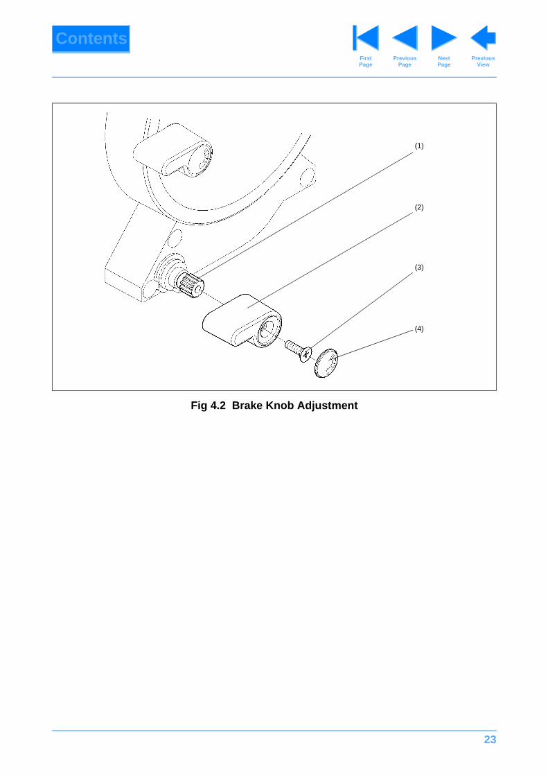
11 The procedure for resetting the pan and tilt brake knobs is as follows (Fig 4.2):
11.1 Prise out the centre of the appropriate brake knob (4).
11.2 Turn the knob (2) clockwise to fully apply the brake.
11.3 Remove the retaining screw (3) and pull the knob (2) off the shaft (1).
11.4 Refit the knob on the shaft in the vertical position.
11.5 Turn the knob fully counter-clockwise and ensure the brake is released
11.6 Turn the knob clockwise and ensure that the brake is fully applied when the knob is vertical. Adjust the position of the knob if necessary.
11.7 Secure the knob with the screw (3). Refit the knob centre (4), using Silcoset 153.
23
ContentsPrevious
PageFirst Page
Next Page
Previous View
Fig 4.2 Brake Knob Adjustment
(1)
(2)
(3)
(4)
24
ContentsPrevious
PageFirst Page
Next Page
Previous View
Section 5
Repair
Contents Para
General. . . . . . . . . . . . . . . . . . . . . . . . . . . . . . . . . . . . . . . . . . . . . . . . . . . . . . . . . . . . . . . . . . . . . . . . . . . . . . 1
Disassembly
Platform . . . . . . . . . . . . . . . . . . . . . . . . . . . . . . . . . . . . . . . . . . . . . . . . . . . . . . . . . . . . . . . . . . . . . . . . . . . 3
Tilt mechanism. . . . . . . . . . . . . . . . . . . . . . . . . . . . . . . . . . . . . . . . . . . . . . . . . . . . . . . . . . . . . . . . . . . . . . 4
Balance mechanism. . . . . . . . . . . . . . . . . . . . . . . . . . . . . . . . . . . . . . . . . . . . . . . . . . . . . . . . . . . . . . . . . . 6
Pan mechanism . . . . . . . . . . . . . . . . . . . . . . . . . . . . . . . . . . . . . . . . . . . . . . . . . . . . . . . . . . . . . . . . . . . . . 7
Mechanism housing assembly. . . . . . . . . . . . . . . . . . . . . . . . . . . . . . . . . . . . . . . . . . . . . . . . . . . . . . . . . . 8
Assembly
Pan mechanism . . . . . . . . . . . . . . . . . . . . . . . . . . . . . . . . . . . . . . . . . . . . . . . . . . . . . . . . . . . . . . . . . . . . 10
Tilt mechanism. . . . . . . . . . . . . . . . . . . . . . . . . . . . . . . . . . . . . . . . . . . . . . . . . . . . . . . . . . . . . . . . . . . . . .11
Balance mechanism. . . . . . . . . . . . . . . . . . . . . . . . . . . . . . . . . . . . . . . . . . . . . . . . . . . . . . . . . . . . . . . . . 12
Platform . . . . . . . . . . . . . . . . . . . . . . . . . . . . . . . . . . . . . . . . . . . . . . . . . . . . . . . . . . . . . . . . . . . . . . . . . . 14
Final assembly . . . . . . . . . . . . . . . . . . . . . . . . . . . . . . . . . . . . . . . . . . . . . . . . . . . . . . . . . . . . . . . . . . . . . 15
General
1 This section details procedures for disassembly and assembly of the Vision 10LF Head, where such operations are not self-evident. Reference is made in the procedures to figures in the Illustrated Parts List (Section 6).
2 The head is constructed from precision components, many of which are of aluminium alloy. Several of the assembly procedures require the use of special tools and specific sealants, adhesives or lubricants. It is advised that only experienced and properly equipped personnel with access to all necessary tools and materials should attempt to overhaul, repair or replace components on these heads. The tools and consumable materials required for work on Vision 10LF heads are listed in Section 3.
25
ContentsPrevious
PageFirst Page
Next Page
Previous View
Disassembly
Platform
3 To remove the platform, proceed as follows (Fig 6.3):
3.1 Remove the platform slide (Section 2)
3.2 Remove the graphic (38).
3.3 Remove one screw (36) and four screws (8), noting that screws are secured with Loctite. Carefully lift the LH side of the platform and retain the platform slide release spring (28) which will be released as the platform is lifted.
3.4 Turn the platform slide clamp lever (4) upwards and separate the platform from RH side plate (7). Collect the slide clamp strip (10) as it is released.
3.5 Remove the platform slide release (27) by feeding it up through the platform.
3.6 If required, unscrew and remove slide clamp screw (3). Unscrew grub screw (5) and remove slide clamp lever (4).
Tilt mechanism
4 To remove the tilt mechanism, proceed as follows (Fig 6.3):
4.1 Remove the platform (Para 3).
4.2 Turn the balance knob (13) fully counter-clockwise.
4.3 Remove two screws (25) and two screws (26), noting that screws are secured with Loctite.
4.4 Pull the tilt mechanism off the head. Retain shim (9) and shims (19).
4.5 It is not necessary to remove the mechanism housing cover (21) from the mechanism housing assembly (16) unless replacement of the bearing (22) or access to the balance mechanism or RH side plate is required. The cover is secured by three screws (23). The bearing (22) is a press fit in the housing and is secured with Loctite. Heat the housing to 80°C to facilitate removal.
5 To dismantle the tilt mechanism, proceed as follows (Fig 6.4):
WARNING!: Ensure that balance knob is turned fully counter-clockwise before remov-ing the tilt mechanism.
NOTE: When the tilt mechanism is pulled off the head the balance mechanism will be under spring tension.
NOTE: This unit contains Vinten Fluid No. 3. A good supply of clean rag should be to hand.
26
ContentsPrevious
PageFirst Page
Next Page
Previous View
5.1 Remove the tilt drag knob cap (23). Remove the screw (24) and pull off the tilt drag knob (16).
5.2 Remove three screws (25) securing tilt drag knob retainer (26). Remove the retainer, the tilt drag knob boss (10) (complete with drag knob retaining shaft (14) and the two thrust washers and the thrust race (12), noting orientation of components for assembly. The drag knob retaining shaft (14) is secured in the tilt drag knob boss (11) with Loctite.
5.3 On the pan and tilt brakes, prise off the covers (22), remove the screws (21) and pull off the knobs (20). Unscrew the two brake shafts (19 and 27), noting their orientation. Retain the friction element (18) and spring element (17) from each shaft and the insert (28) from the end of the tilt brake shaft.
5.4 Remove six screws (2) which secure the tilt drag cover/brake disc assembly (31) to the tilt drag housing (1). Separate the cover and housing, remembering that a quantity of Vinten Fluid No. 3 is contained in the housing. Discard `O' ring (32).
5.5 Remove two screws (36) securing drag shoe assembly (35). Remove drag shoe assembly, drag actuator shaft (3), washer (4) and `O' ring (5). Discard `O' ring.
5.6 Turn the tilt drag cover/brake disc assembly (31) so that the cutout in the brake disc aligns with the tilt brake plate (29). Pull the assembly off the tilt bearing housing (33). Note the orientation of the omniseal (8), with the open side facing towards the drag shoe. Remove and discard the omniseal.
5.7 Remove screw (6) and two screws (34) securing tilt bearing housing (33) to outrigger (9). Remove and discard `O' ring (5). Remove bearing (7).
5.8 Remove three screws (30) securing tilt brake plate (29) to outrigger (9).
5.9 Pull out pan brake pivot (13) and remove pan brake shoe assembly (12).
NOTE: Early brake shafts (to Serial No. 1382) are solid. Later brake shafts are fitted with spring and friction elements (17 and 18) to improve performance. Early brake shafts should be replaced by later brake shafts and spring and friction elements.
NOTE: The design of the tilt brake cover/brake disc assembly changed from Serial No. 1197. Ensure correct housing and ‘O’ ring are replaced.
27
ContentsPrevious
PageFirst Page
Next Page
Previous View
Balance mechanism
6 To remove the balance mechanism, proceed as follows (Fig 6.3):
6.1 Remove the platform (Para 3).
6.2 Remove the tilt mechanism and mechanism housing cover (Para 4).
6.3 Using circlip pliers, remove Spirol ring (14) from groove in mechanism housing assembly (16) and allow it to rest on the neck of the balance knob assembly (13).
6.4 Unscrew and remove the balance knob assembly (13) together with Spirol ring (14).
6.5 Remove the thrust race and two thrust washers (12), noting orientation of components for assembly.
6.6 Remove cap (35) from mechanism housing assembly (16) to gain access to balance mechanism screw (34)
6.7 Undo screw (34) until balance mechanism tension is just relieved.
6.8 Remove needle roller (15).
6.9 Using circlip pliers, release circlip (11) securing RH side plate (7) in mechanism housing assembly. Carefully pull RH side plate out of mechanism housing assembly. Retain shim (9) and shims (19).
6.10 Undo screw (34) as far as possible without separating from actuator shaft (30).
6.11 Manoeuvre balance mechanism out of mechanism housing assembly. Ensure all shims and circlip (11) are removed from mechanism housing assembly.
6.12 The balance mechanism may now be dismantled if required. Do not remove pins from spring actuator (30)
Pan mechanism
7 To remove/dismantle the pan mechanism proceed as follows (Fig 6.5):
7.1 Remove the platform (Para 3).
7.2 Remove the tilt mechanism and mechanism housing cover (Para 4).
7.3 Remove the balance mechanism (Para 6).
WARNING!: The balance mechanism spring tension is preset. Do not remove or dis-mantle the balance mechanism unless necessary.
NOTE: This unit contains Vinten Fluid No. 3. A good supply of clean rag should be to hand.
28
ContentsPrevious
PageFirst Page
Next Page
Previous View
7.4 Remove the pan drag knob cap (1). Remove the screw (2) and pull off the pan drag knob (3).
7.5 Unscrew and remove the pan drag shaft (6), together with pan drag push rod (8). Retain washers (7). The pan drag knob boss (5) is secured to the shaft with Loctite.
7.6 Slacken the pan drag lever screw (28) and lift the pan drag lever (29) and actuator shim (27) off the drag actuator (12).
7.7 Remove screw (26) and washer (25) from end of bowl clamp stud (21)
7.8 Remove six screws (18) which secure the spherical base (17) to pan drag top plate (14). Gently ease the base away from the top plate. When the base is removed it will contain most of the Vinten Fluid No. 3. The bowl clamp stud (21) is secured to the base using Loctite. Remove and discard `O' ring (16).
7.9 Remove two screws (19) securing drag shoe assembly (15). Remove drag shoe assembly and the pan drag actuator (12). Remove and discard `O' ring (11).
7.10 Remove pan drag top plate (14) and the thrust race and two thrust washers (13), noting orientation of components for assembly. Note the orientation of omniseal (20), with the open side facing towards the spherical base. Remove and discard the omniseal.
7.11 Remove two screws (22) securing pan bearing housing (10) to mechanism housing assembly (9). Remove and discard `O' ring (21) from groove in pan bearing housing.
7.12 If required, remove bearing (24) from mechanism housing assembly. The bearing is secured with Loctite.
Mechanism housing assembly
8 If required, the bearing (Fig 6.2, item 4) may be removed from mechanism housing assembly. The bearing is a press fit and is secured with Loctite.
Assembly
Mechanism housing assembly
9 If the bearing (Fig 6.2, item 4) has been removed from mechanism housing assembly a replacement may be installed without heating the housing. It is essential that a suitable press, fitted with a mandrel adaptor and support ring to match the bearing, is used. Proceed as follows:
9.1 Remove all traces of adhesive from bearing and seating in mechanism housing assembly. Degrease bearing seating and outer race of bearing.
NOTE: The design of the pan drag top plate and spherical base changed from Serial No. 1197. Ensure correct top plate, spherical base and ‘O’ ring are replaced.
NOTE: It is important for correct operation of the head that torque settings, where given, are achieved.
29
ContentsPrevious
PageFirst Page
Next Page
Previous View
9.2 Apply Loctite 641 to outer race of bearing and press into mechanism housing assembly, ensuring bearing is correctly seated.
Pan mechanism
10 Assemble the pan mechanism as follows (Fig 6.5):
10.1 Lightly lubricate components as follows:
10.1.1 All moving surfaces, particularly `O' rings and seals (11, 16, 20 and 23), spherical end of pan drag push rod (8), drag actuator (12) and bearing (24) using white bearing grease. This grease must not be allowed to come into contact with the drag surfaces.
10.1.2 Thread of pan drag shaft (6) with Rocol M204G grease.
10.1.3 Contact surfaces of drag shoe (15) and bearing housing (10), except for the area around clamping screws (19), with grease GP50. This grease must not be allowed to come into contact with the drag surfaces.
10.2 The correct orientation of the Omniseal (20), as shown in Fig 6.5 is important. Renew the seal.
10.3 Fit new `O' rings and seals throughout.
10.4 Prior to assembly fill the base (17) with 12.75 cc of Vinten Fluid No. 3 (Section 3).
10.5 Install bearing (24) in mechanism housing (9) and secure with Loctite 641.
10.6 Install `O' ring (23) in pan bearing housing (10). Secure pan bearing housing to mechanism housing (9) with two screws (22) and Loctite 222E, ensuring pan bearing housing is centralized on mechanism housing.
10.7 Install Omniseal (20) in pan drag top plate (14), observing correct orientation.
10.8 Install the thrust race and two thrust washers (13) in pan drag top plate (14), observing correct orientation.
10.9 Position pan drag top plate and assemble components over the pan bearing housing (10).
10.10 Install `O' ring (11) on drag actuator (12). Position actuator in drag shoe assembly (15) and install both on the pan bearing housing (10). Secure temporarily with two screws (19)
10.11 Install pan drag lever (29) on drag actuator and secure temporarily with screw (28).
10.12 Install washers (7) and pan drag push road (8) in pan drag shaft (6), Screw pan drag shaft (complete with pan drag knob boss (5)) into mechanism housing (9).
10.13 Install assembly in pan centralizing fixture (3390-904TL).
10.14 Screw in pan drag shaft (6) to expand drag shoe assembly.
NOTE: The design of the pan drag top plate and spherical base changed from Serial No. 1197. Ensure correct top plate, spherical base and ‘O’ ring are replaced.
30
ContentsPrevious
PageFirst Page
Next Page
Previous View
10.15 Remove screws (19) one at a time and reinstall using Loctite 221. Torque-tighten screws to 5.08 Nm (45 lbf in.).
10.16 Remove pan drag shaft (6), pan drag push road (8) and pan drag lever (29).
10.17 Remove assembly from centralizing fixture.
10.18 Install `O' ring (16) in spherical base (17).
10.19 Prime six screws (18) with Loctite N primer and allow to dry.
10.20 Position spherical base over drag shoe assembly and secure with six screws (18), using Loctite 222E.
10.21 Prime screw (26) with Loctite T primer and allow to dry.
10.22 Install screw (26) and washer (25) in clamp stud (20) using Loctite 241. Tighten screw (26) down hard to bed in parts, then slacken and torque-tighten to 0.56 Nm (5 lbf in.).
10.23 Install actuator shim (27) and pan drag lever (29) on drag actuator (12).
10.24 Prime screw (28) with Loctite N primer and allow to dry.
10.25 Secure pan drag lever (29) with screw (28), using Loctite 222E.
10.26 Screw in pan drag shaft (6) and pan drag push road (8) (complete with pan drag knob boss (5)).
10.27 Turn the pan drag knob boss (5) clockwise until any slack is taken up and drag begins to be felt Install pan drag knob (3) on pan drag shaft (6), with `1' aligned with the index mark on mechanism housing.
10.28 Apply maximum drag and ensure pin (4) does not foul face of casting (9). If necessary, dismantle pan drag shaft (6) and pan drag push road (8) and install washers (7) as required.
10.29 Secure pan drag knob (3) with screw (2), but do not tighten. The pan drag knob is adjusted after assembly of the head.
Tilt mechanism
11 Assemble the tilt mechanism as follows (Fig 6.4):
11.1 Lightly lubricate components as follows:
11.1.1 All moving surfaces, particularly `O' rings and seals (5, 8 and 32), drag actuator (3) and bearing (7) using white bearing grease. This grease must not be allowed to come into contact with the drag surfaces.
11.1.2 Contact surfaces of drag shoe (35) and bearing housing (33), except for the area around clamping screws (36), with grease GP50. This grease must not be allowed to come into contact with the drag surfaces.
11.2 The correct orientation of the Omniseal (8), as shown in Fig 6.4 is important. Renew the seal.
11.3 Fit new `O' rings and seals throughout.
11.4 Install Omniseal (8) in the tilt drag cover/brake disc assembly (31), observing correct orientation.
31
ContentsPrevious
PageFirst Page
Next Page
Previous View
11.5 Fill the tilt drag housing (1) with 16.25 cc of Vinten Fluid No. 3 (Section 3).
11.6 Install bearing (7) in outrigger (9).
11.7 Degrease and prime two screws (34) and one screw (6) with Loctite N primer and allow to dry.
11.8 Install `O' ring (5) in tilt bearing housing (33) and secure to outrigger (9) with two screws (34) and one screw (6) and Loctite 222E.
11.9 Degrease and prime three screws (30) with Loctite N primer and allow to dry.
11.10 Install tilt brake plate (29) on outrigger (9) and secure with three screws (30) and Loctite 222E.
11.11 Align cutout in tilt drag cover/brake disc assembly (31) with tilt brake plate (29) and push the assembly onto the tilt bearing housing (33). Take care not to damage the omniseal (8).
11.12 Install `O' ring (5) and washer (4) in the tilt bearing housing (33).
11.13 Install drag shoe assembly (35) on the tilt bearing housing (33). Secure temporarily with two screws (36).
11.14 Install drag actuator shaft (3).
11.15 Install assembly in tilt centralizing fixture (3390-905TL).
11.16 Using the fixture, expand the drag shoe assembly.
11.17 Remove screws (36) one at a time and reinstall using Loctite 221 on threads and Loctite 601 under heads. Torque-tighten screws to 7.34 Nm (65 lbf in.).
11.18 Remove from fixture.
11.19 Install `O' ring (32) in tilt drag cover/brake disc assembly (31).
11.20 Degrease and prime six screws (2) with Loctite N primer and allow to dry.
11.21 Install completed outrigger assembly on tilt drag housing (1). Align fixing holes and secure with six screws (2) and Loctite 222E.
11.22 Install pan brake pivot (13) in pan brake shoe assembly (12) and install in tilt mechanism.
11.23 The remaining tilt mechanism components are installed after assembly of the balance mechanism.
NOTE: The design of the tilt brake cover/brake disc assembly changed from Serial No. 1197. Ensure correct housing and ‘O’ ring are replaced.
32
ContentsPrevious
PageFirst Page
Next Page
Previous View
Balance mechanism
12 Assemble/install the balance mechanism as follows (Fig 6.3):
12.1 If the bearing (22) has been removed from the mechanism housing cover (21) a replacement may be installed without heating the cover. It is essential that a suitable press, fitted with a mandrel adaptor and support ring to match the bearing, is used. Proceed as follows:
12.1.1 Remove all traces of adhesive from bearing and seating in mechanism housing cover. Degrease bearing seating and outer race of bearing.
12.1.2 Apply Loctite 641 to outer race of bearing and press into mechanism housing cover, ensuring bearing is correctly seated.
12.2 Assemble the pan mechanism (Para 10)
12.3 Assemble the tilt mechanism (Para 11).
12.4 Using Loctite 495, adhere buffer (32) to end washer (33).
12.5 Lightly lubricate components as follows:
12.5.1 All moving contact surfaces of the balance mechanism with grease GP50.
12.5.2 All bearings and shims with white bearing grease.
12.6 Fit equal numbers of shim washer (19) on each side of bearing (18) to minimise side play between the adjuster slide (17) and actuator shaft (29).
12.7 Using tool 3431-912TL, secure dowel (20) in adjustment slide (17) using Loctite 601.
12.8 Assemble actuator shaft (29), spring actuator (30), spring (31) and end washer (33).
12.9 Apply Loctite 270 to screw (34) and tighten to allow about 2 mm (1/12 in.) clearance.
12.10 Position circlip (11) inside the mechanism housing.
12.11 Install two shim washers (19) on spring actuator (30). Holding the assembled balance mechanism with the slot in the adjustment slide (17) facing downwards, position the balance mechanism in the mechanism housing (16).
12.12 Turn the balance mechanism through 90°, until the slot in the adjustment slide (17) aligns with the hole in the mechanism housing (16) and needle roller (15) can be pushed fully home.
12.13 Install bearing shim (9) on RH side plate (7).
12.14 Install RH side plate (7) in mechanism housing (16), ensuring spring actuator (31) engages with needle bearing. Secure with circlip (11).
12.15 Install mechanism housing cover (21) on mechanism housing (16) and secure with three screws (23).
NOTE: The remaining assembly of the balance mechanism, side plate, tilt mechanism and final adjustment of the balance spring must be completed before the Loctite on screw (35) sets.
33
ContentsPrevious
PageFirst Page
Next Page
Previous View
12.16 Before installing the tilt mechanism, degrease the pan brake contact surface on the pan drag top plate (Fig 6.5, item 14)
12.17 Install bearing shim (9) on tilt mechanism (24).
12.18 Install tilt mechanism (24) in mechanism housing (16), ensuring spring actuator (30) engages with needle bearing. Secure with two screws (25) and two screws (26), using Loctite 222E.
12.19 Working through the hole in the mechanism housing assembly (16), tighten the balance mechanism screw (34) until it just nips the spring, then tighten a further two full turns to preload the spring.
12.20 Using Loctite, install cap (35) in hole in the mechanism housing assembly (16).
12.21 Lubricate the thrust washer components (12) with white bearing grease and install in mechanism housing (16), ensuring orientation is as noted during disassembly.
12.22 Lubricate the shaft of the balance knob assembly (13) with M204G grease screw into the adjustment slide (17). Secure balance knob with Spirol ring (14).
13 Install the remaining tilt mechanism components as follows (Fig 6.4):
13.1 Install spring element (17) and friction element (18) in each brake shaft (19, 27). Install tilt brake insert (28) in tilt brake shaft (27).
13.2 Screw both brake shafts into outrigger (9) as far as they will go and install a brake knob (20) on each shaft so that, when fully applied the knob is vertical and, when turned fully counter-clockwise, the brake is off. Secure each knob with a screw (21) and Loctite 222E. Secure cap (22) to each knob with Silcoset.
13.3 Lubricate the thrust washer components (10) with white bearing grease and install in outrigger (9), ensuring orientation is as noted during disassembly.
13.4 Lubricate the tilt drag knob boss (11) with M204G grease and install, complete with drag knob retaining shaft (14), in the thrust bearing (10). Secure with tilt drag retainer/stop (26) and three screws (25).
13.5 Turn the tilt drag boss (11) clockwise until any slack is taken up, then turn the outrigger in both directions to confirm that movement is smooth and quiet. Degrease thread in drag knob retaining shaft (14).
13.6 Install tilt drag knob (16) on drag knob retaining shaft (14), with `0' aligned with the index mark on outrigger. Secure with screw (24), but do not tighten. The tilt drag knob is adjusted after assembly of the head.
Platform
14 To install the platform, proceed as follows (Fig 6.3):
14.1 If removed, install dowel pin (42) in platform (41) to leave the end projecting 3.5 mm. Loctite 638 may be used to secure the dowel pin if required.
14.2 Degrease three threaded holes in the top face of tilt housing (24), two threaded holes in the edge of platform (7), one screw (36). and four screws (8).
34
ContentsPrevious
PageFirst Page
Next Page
Previous View
14.3 Support the head securely in an upright position and set the top surfaces of the tilt drag housing and the RH side plate approximately level.
14.4 Locate slide clamp strip (10) in the slot in the underside of the platform and hold it in position using the rounded end of tool 3390-909TL inserted from the top face of the platform. Insert slide release (27) downwards through the hole in the platform to locate in the underside of the platform. Ensure that the slide release is free to move and is inserted with its slot towards the centre of the platform.
14.5 Holding the slide release in the fully out position, tilt the RH edge of the platform down and engage the lug on the side of the platform in the notch in the RH side plate. Lower the LH side of the platform into position on the top face of the tilt unit housing, ensuring that the lugs on the underside of the platform enter the corresponding slots in the top face of the tilt unit housing and the 2 mm dia Spirol pin in the top of the tilt unit housing enters the slot in the slide release. Remove tool 3390-909TL.
14.6 Position spring (28) on the cylindrical end of tool 3390-909TL. Holding the tool so that the cylindrical end points slightly downward, lift the LH side of the platform just enough to allow the spring to be introduced between the top face of the slide release and the underside of the platform. Use the tool to guide the free end of the spring into the slot in the slide release, compress the spring against the 2 mm dia Spirol pin until its outer end drops into the slot in the slide release, lower the platform to rest on the tool and withdraw the tool.
14.7 Apply Loctite 222E to screw (26) and four screws (8) and secure the platform to the RH side plate and the tilt unit housing.
14.8 Confirm that the slide release operates freely and that the spring returns it to the outward position.
14.9 Insert platform slide (1) into the rear end of the platform dovetails, check that it is retained at the front end by the dowel pin and at the back end by the slide release.
14.10 Apply white bearing grease to the threads of clamp screw (3) and screw it into the lug on the RH side of the platform to clamp the platform slide.
14.11 Degrease grub screw (5), apply Loctite 222E to the threads and install in knob (4). Fit knob (4) on the hexagonal part of clamp screw (3) so that the platform slide is clamped when the arm points vertically downwards and is free when the knob is turned counter-clockwise to the stop. Tighten grub screw (5) to secure the knob.
Final assembly
15 The pan and tilt drag control knobs are set so that drag begins to be felt between 1 and 1.5 on the scale. Set the drag knobs as detailed in Section 4.
35
ContentsPrevious
PageFirst Page
Next Page
Previous View
Section 6
Illustrated Parts List
Contents Para
Introduction . . . . . . . . . . . . . . . . . . . . . . . . . . . . . . . . . . . . . . . . . . . . . . . . . . . . . . . . . . . . . . . . . . . . . . . . . . 1
Ordering spare parts. . . . . . . . . . . . . . . . . . . . . . . . . . . . . . . . . . . . . . . . . . . . . . . . . . . . . . . . . . . . . . . . . . . 2
Main assembly part numbers. . . . . . . . . . . . . . . . . . . . . . . . . . . . . . . . . . . . . . . . . . . . . . . . . . . . . . . . . . . . 5
Illustrations Page
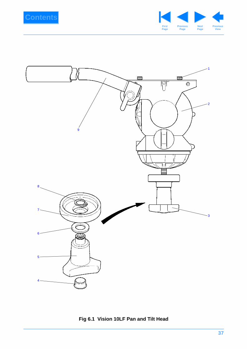
Fig 6.1 Vision 10LF Pan and Tilt Head . . . . . . . . . . . . . . . . . . . . . . . . . . . . . . . . . . . . . . . . . . . . . . . . . . . . . 37
Fig 6.2 Vision 10LF Pan and Tilt Head - Mechanism Housing Assembly . . . . . . . . . . . . . . . . . . . . . . . . . . . 39
Fig 6.3 Vision 10LF Pan and Tilt Head - Platform and Balance Mechanism. . . . . . . . . . . . . . . . . . . . . . . . . 41
Fig 6.4 Vision 10LF Pan and Tilt Head - Tilt Mechanism . . . . . . . . . . . . . . . . . . . . . . . . . . . . . . . . . . . . . . . 44
Fig 6.5 Vision 10LF Pan and Tilt Head - Pan Mechanism. . . . . . . . . . . . . . . . . . . . . . . . . . . . . . . . . . . . . . . 47
Fig 6.6 Vision 10LF Pan and Tilt Head - Pan Bar . . . . . . . . . . . . . . . . . . . . . . . . . . . . . . . . . . . . . . . . . . . . . 50
Fig 6.7 Vision 10LF Pan and Tilt Head - Composite Spare parts . . . . . . . . . . . . . . . . . . . . . . . . . . . . . . . . . 52
Introduction
1 This parts list is issued for the VISION 10LF pan and tilt head manufactured by VINTEN BROADCAST LIMITED, Western Way, Bury St Edmunds, Suffolk, IP33 3TB, England.
Ordering spare parts
2 Always quote the head serial number when ordering a spare part.
3 When ordering a spare part, please quote the part number, NOT the item number. Certain part numbers have a -900SP series suffix, which denotes a composite spare part. These items are detailed in Fig 6.7 and indicated in the parts lists by an asterisk (*) against the part number.
4 Due to restrictions placed on the transport of adhesives and other materials, please obtain supplies of consumable materials, listed in Section 3, from your local distributor.

36
ContentsPrevious
PageFirst Page
Next Page
Previous View
Main assembly part numbers
5 Please ensure that the correct part number is quoted when ordering main assemblies.
Assembly Part No.
Vision 10LF pan and tilt head - final assembly 3390-11
Pan bar 3219-21
Bowl clamp assembly 3390-18
Camera mounting plate 3364-900SP
37
ContentsPrevious
PageFirst Page
Next Page
Previous View
Fig 6.1 Vision 10LF Pan and Tilt Head
1
2
3
4
9
7
6
5
8
38
ContentsPrevious
PageFirst Page
Next Page
Previous View
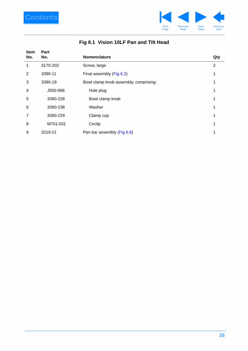
Fig 6.1 Vision 10LF Pan and Tilt Head
ItemNo.
Part No. Nomenclature Qty
1 3170-202 Screw, large 2
2 3390-11 Final assembly (Fig 6.2) 1
3 3390-18 Bowl clamp knob assembly, comprising: 1
4 J550-068 Hole plug 1
5 3390-228 Bowl clamp knob 1
6 3390-238 Washer 1
7 3390-229 Clamp cup 1
8 M701-031 Circlip 1
9 3219-21 Pan bar assembly (Fig 6.6) 1
39
ContentsPrevious
PageFirst Page
Next Page
Previous View
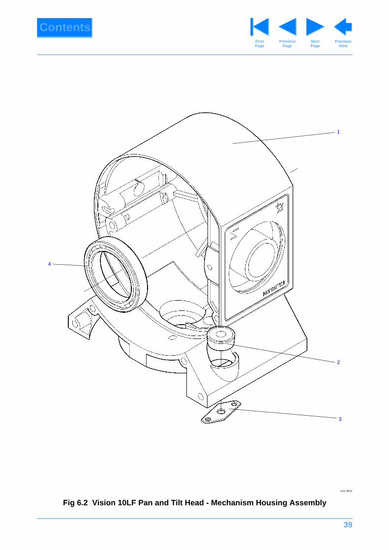
Fig 6.2 Vision 10LF Pan and Tilt Head - Mechanism Housing Assembly
2
1
4
3
V10_IPO2

40
ContentsPrevious
PageFirst Page
Next Page
Previous View
Fig 6.2 Vision 10LF Pan and Tilt Head - Mechanism Housing Assembly
ItemNo.
Part No. Nomenclature Qty
1 3390-201 Mechanism housing 1
2 3322-263 Level bubble 1
3 3321-214 Level bubble sealing strip 1
4 P302-011 Bearing, ball, radial, 30 mm ID x 42 mm OD x 7 mm long 1
41
ContentsPrevious
PageFirst Page
Next Page
Previous View
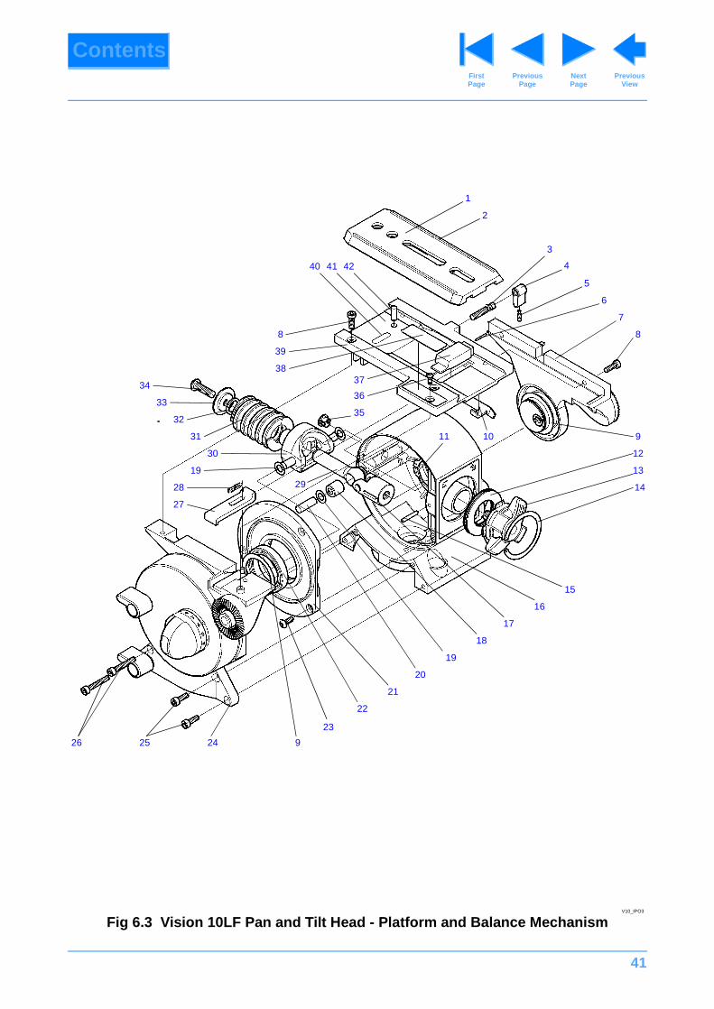
Fig 6.3 Vision 10LF Pan and Tilt Head - Platform and Balance Mechanism
1
2
5
3
4
6
7
8
910
12
13
14
15
16
17
18
19
20
21
11
22
26
27
19
29
30
28
31
32
33
34 37
36
35
8
39
38
40 41 42
23
92425
V10_IPO3
42
ContentsPrevious
PageFirst Page
Next Page
Previous View
Fig 6.3 Vision 10LF Pan and Tilt Head - Platform and Balance Mechanism
ItemNo.
Part No. Nomenclature Qty
1 3364-210* Platform slide 1
2 Q001-093* 'O' ring, 3 3/4 in. id x 1/16 in. sect 1
3 3321-278 Screw, slide clamp 1
4 3325-343 Slide clamp lever 1
5 M004-804* Grub screw, skt M3 x 10 mm lg 1
6 M806-033 Spirol pin, 1.5 mm dia. x 12 mm lg 1
7 3390-903SP* RH side plate assembly 1
8 M005-735* Screw, low profile, cap hd, m4 x 12 mm lg 4
9 3321-226 Bearing shim 2
10 3321-255 Slide clamp strip 1
11 M701-036 Circlip, external (30 mm shaft) 1
12 Thrust bearing, comprising:
P602-021 Thrust washer, 25 mm x 42 mm x 1 mm 2
P602-020 Thrust race, needle, 25 mm x 42 mm x 1 mm 1
13 3390-17 Balance knob assembly 1
14 3390-232 Spirol ring 1
15 P600-012 Needle roller, 3 mm dia x 17.8 mm lg 1
16 3390-14 Mechanism housing assembly (Fig 6.2)
17 3321-220 Adjustment slide 1
18 N500-023 Bearing, needle, 1/4 in. x 7/16 in. x 7/16 in. 1
19 3321-222 Shim washer 6
20 L801-098 Dowel pin, 1/4 in. oversize dia x 3/4 in. lg 1
21 3390-223 Mechanism housing cover 1
22 P302-011 Radial bearing, 30 mm x 42 mm x 7 mm 1
23 M005-504* Screw, button hd, M4 x 10 mm lg 3
24 Tilt mechanism (Fig 6.4)
25 M005-718* Screw, skt cap hd, M4 x 12 mm lg 2
26 M005-721* Screw, skt cap hd, M4 x 25 mm lg 2
27 3364-285 Slide release 1
28 J532-109 Spring, compression, 5/32 in. OD x 3/32 in. ID x 3/4 in. lg 1
29 3390-231 Actuator shaft 1
43
ContentsPrevious
PageFirst Page
Next Page
Previous View
30 3364-908SP* Spring actuator 1
31 J532-108 Spring, compression, 1 1/4 in. OD x 5/8 in. ID x1 3/4 in. lg 1
32 3321-223 Buffer 1
33 3321-224 End washer 1
34 M007-523* Screw, skt button hd, M6 x 20 mm lg 1
35 3325-354 Cap 1
36 M004-503* Screw, skt button hd, M3 x 8 mm lg 1
37 3321-284 Platform insert 1
38 3364-284 Top graphic 1
39 3321-254 Platform 1
40 3390-225 Serial No. label 1
41 3390-224 Platform graphic 1
42 M801-048 Dowel pin, 5 mm dia x 12 mm lg 1
Fig 6.3 Vision 10LF Pan and Tilt Head - Platform and Balance Mechanism (Cont)
ItemNo.
Part No. Nomenclature Qty
44
ContentsPrevious
PageFirst Page
Next Page
Previous View
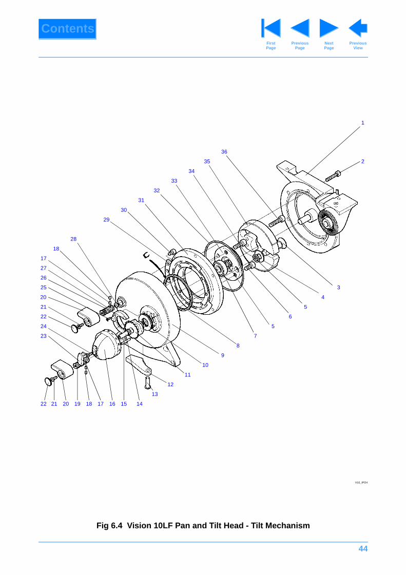
Fig 6.4 Vision 10LF Pan and Tilt Head - Tilt Mechanism
1
3
4
5
6
5
7
8
9
10
11
12
19
13
1417
20
2
36
35
34
33
21
31
30
24
18
23
22 21 15161820
28
22
29
32
25
26
27
17
V10_IPO4
45
ContentsPrevious
PageFirst Page
Next Page
Previous View
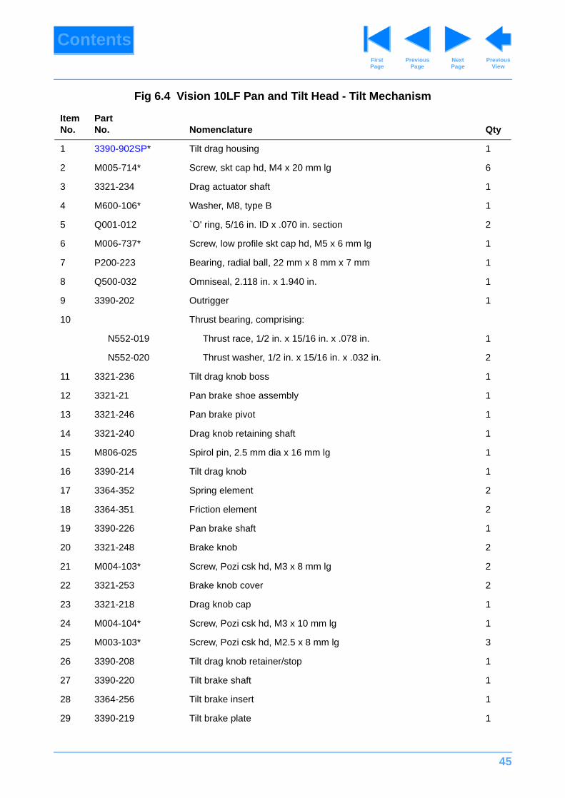
Fig 6.4 Vision 10LF Pan and Tilt Head - Tilt Mechanism
ItemNo.
Part No. Nomenclature Qty
1 3390-902SP* Tilt drag housing 1
2 M005-714* Screw, skt cap hd, M4 x 20 mm lg 6
3 3321-234 Drag actuator shaft 1
4 M600-106* Washer, M8, type B 1
5 Q001-012 `O' ring, 5/16 in. ID x .070 in. section 2
6 M006-737* Screw, low profile skt cap hd, M5 x 6 mm lg 1
7 P200-223 Bearing, radial ball, 22 mm x 8 mm x 7 mm 1
8 Q500-032 Omniseal, 2.118 in. x 1.940 in. 1
9 3390-202 Outrigger 1
10 Thrust bearing, comprising:
N552-019 Thrust race, 1/2 in. x 15/16 in. x .078 in. 1
N552-020 Thrust washer, 1/2 in. x 15/16 in. x .032 in. 2
11 3321-236 Tilt drag knob boss 1
12 3321-21 Pan brake shoe assembly 1
13 3321-246 Pan brake pivot 1
14 3321-240 Drag knob retaining shaft 1
15 M806-025 Spirol pin, 2.5 mm dia x 16 mm lg 1
16 3390-214 Tilt drag knob 1
17 3364-352 Spring element 2
18 3364-351 Friction element 2
19 3390-226 Pan brake shaft 1
20 3321-248 Brake knob 2
21 M004-103* Screw, Pozi csk hd, M3 x 8 mm lg 2
22 3321-253 Brake knob cover 2
23 3321-218 Drag knob cap 1
24 M004-104* Screw, Pozi csk hd, M3 x 10 mm lg 1
25 M003-103* Screw, Pozi csk hd, M2.5 x 8 mm lg 3
26 3390-208 Tilt drag knob retainer/stop 1
27 3390-220 Tilt brake shaft 1
28 3364-256 Tilt brake insert 1
29 3390-219 Tilt brake plate 1
46
ContentsPrevious
PageFirst Page
Next Page
Previous View
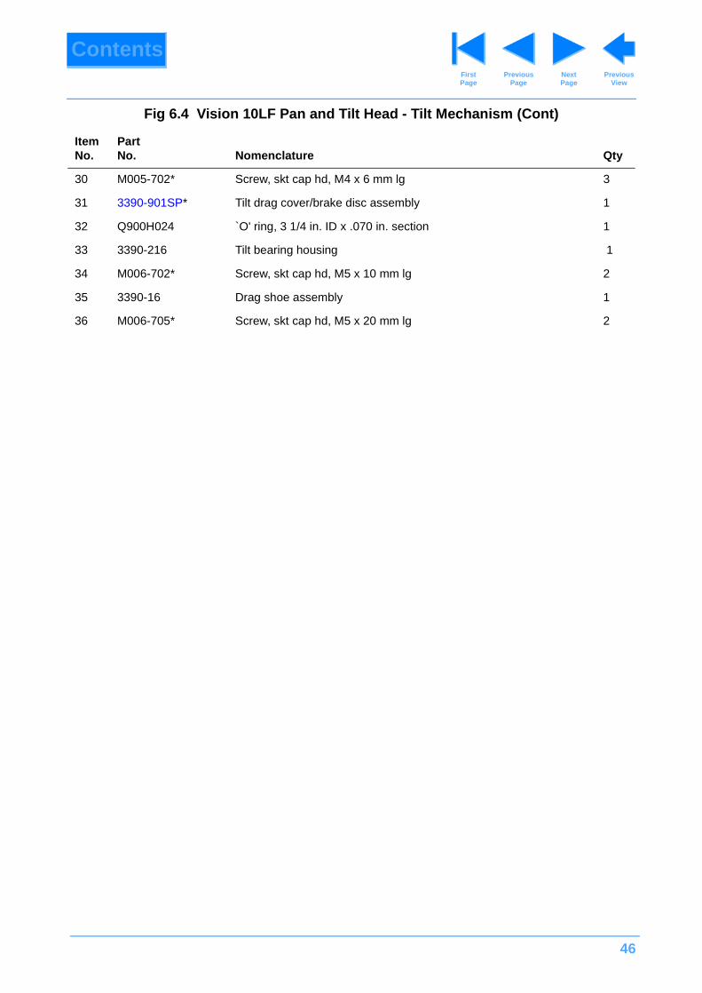
30 M005-702* Screw, skt cap hd, M4 x 6 mm lg 3
31 3390-901SP* Tilt drag cover/brake disc assembly 1
32 Q900H024 `O' ring, 3 1/4 in. ID x .070 in. section 1
33 3390-216 Tilt bearing housing 1
34 M006-702* Screw, skt cap hd, M5 x 10 mm lg 2
35 3390-16 Drag shoe assembly 1
36 M006-705* Screw, skt cap hd, M5 x 20 mm lg 2
Fig 6.4 Vision 10LF Pan and Tilt Head - Tilt Mechanism (Cont)
ItemNo.
Part No. Nomenclature Qty
47
ContentsPrevious
PageFirst Page
Next Page
Previous View
Fig 6.5 Vision 10LF Pan and Tilt Head - Pan Mechanism
12
34
56
7
10
11
12
13
14
15
16
22
21
17
23
19
20
27
29
18
26
24
25
28
V10_IPO5
89
48
ContentsPrevious
PageFirst Page
Next Page
Previous View
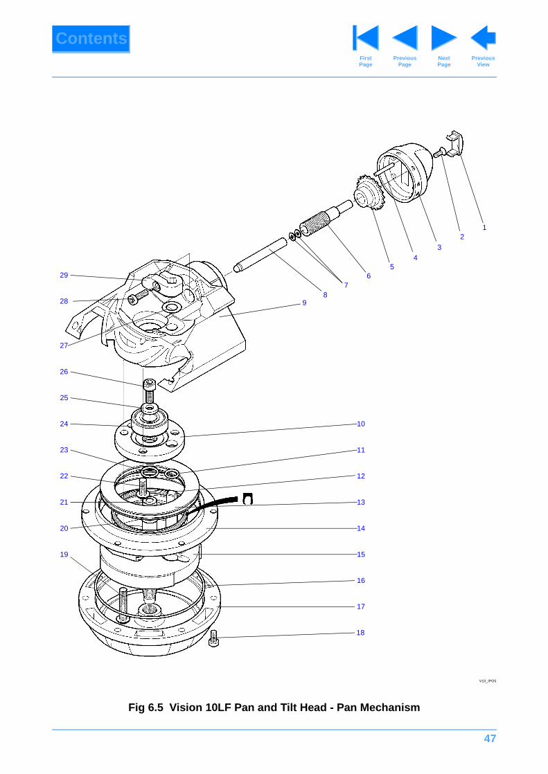
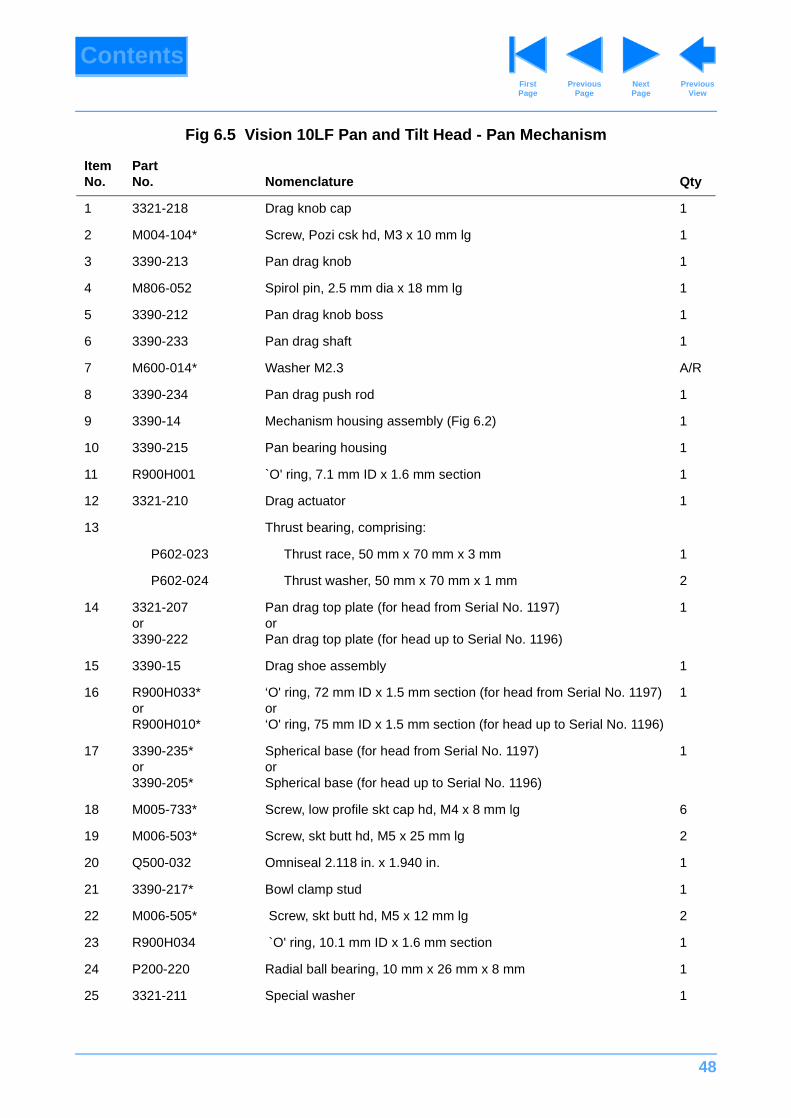
Fig 6.5 Vision 10LF Pan and Tilt Head - Pan Mechanism
ItemNo.
Part No. Nomenclature Qty
1 3321-218 Drag knob cap 1
2 M004-104* Screw, Pozi csk hd, M3 x 10 mm lg 1
3 3390-213 Pan drag knob 1
4 M806-052 Spirol pin, 2.5 mm dia x 18 mm lg 1
5 3390-212 Pan drag knob boss 1
6 3390-233 Pan drag shaft 1
7 M600-014* Washer M2.3 A/R
8 3390-234 Pan drag push rod 1
9 3390-14 Mechanism housing assembly (Fig 6.2) 1
10 3390-215 Pan bearing housing 1
11 R900H001 `O' ring, 7.1 mm ID x 1.6 mm section 1
12 3321-210 Drag actuator 1
13 Thrust bearing, comprising:
P602-023 Thrust race, 50 mm x 70 mm x 3 mm 1
P602-024 Thrust washer, 50 mm x 70 mm x 1 mm 2
14 3321-207or3390-222
Pan drag top plate (for head from Serial No. 1197)orPan drag top plate (for head up to Serial No. 1196)
1
15 3390-15 Drag shoe assembly 1
16 R900H033*orR900H010*
‘O' ring, 72 mm ID x 1.5 mm section (for head from Serial No. 1197)or‘O' ring, 75 mm ID x 1.5 mm section (for head up to Serial No. 1196)
1
17 3390-235*or3390-205*
Spherical base (for head from Serial No. 1197)orSpherical base (for head up to Serial No. 1196)
1
18 M005-733* Screw, low profile skt cap hd, M4 x 8 mm lg 6
19 M006-503* Screw, skt butt hd, M5 x 25 mm lg 2
20 Q500-032 Omniseal 2.118 in. x 1.940 in. 1
21 3390-217* Bowl clamp stud 1
22 M006-505* Screw, skt butt hd, M5 x 12 mm lg 2
23 R900H034 `O' ring, 10.1 mm ID x 1.6 mm section 1
24 P200-220 Radial ball bearing, 10 mm x 26 mm x 8 mm 1
25 3321-211 Special washer 1

49
ContentsPrevious
PageFirst Page
Next Page
Previous View
26 M006-703* Screw, skt cap hd, M5 x 12 mm lg 1
27 3322-229 Actuator shim 1
28 M005-735* Screw, low profile skt csk hd, M4 x 12 mm lg 1
29 3390-207 Pan drag lever 1
Fig 6.5 Vision 10LF Pan and Tilt Head - Pan Mechanism (Cont)
ItemNo.
Part No. Nomenclature Qty
50
ContentsPrevious
PageFirst Page
Next Page
Previous View
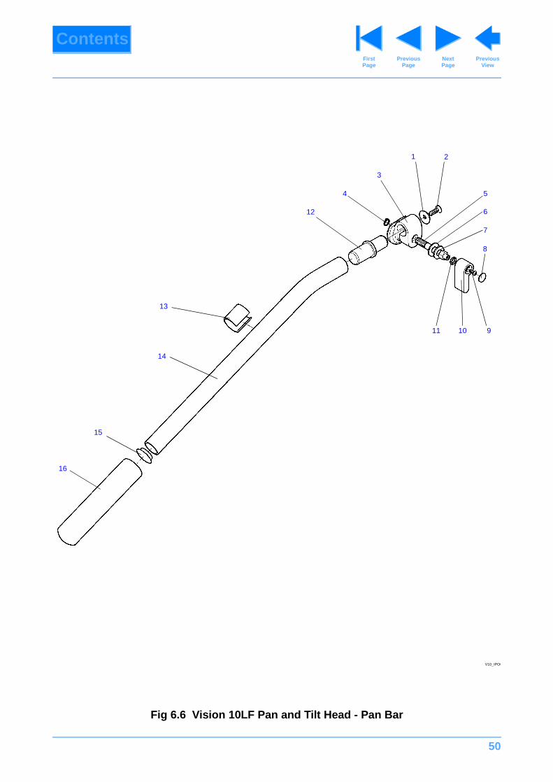
Fig 6.6 Vision 10LF Pan and Tilt Head - Pan Bar
21
9
8
7
6
5
11 10
3
12
4
14
13
15
16
V10_IPO6
51
ContentsPrevious
PageFirst Page
Next Page
Previous View
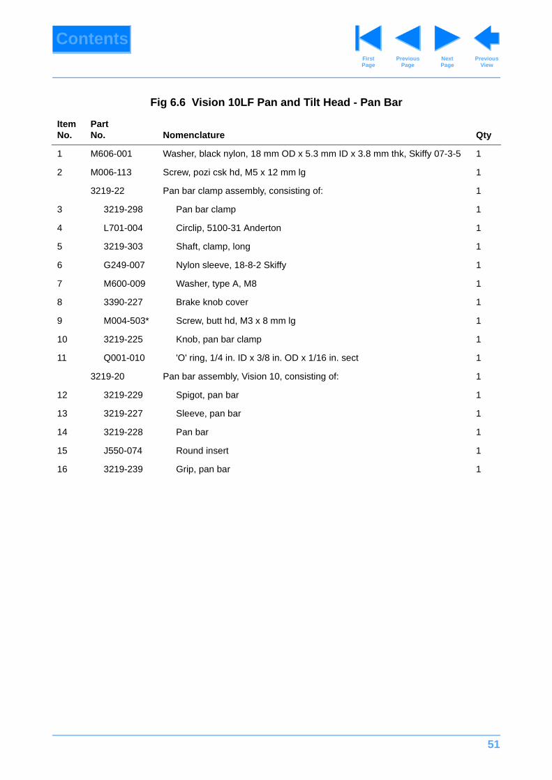
Fig 6.6 Vision 10LF Pan and Tilt Head - Pan Bar
ItemNo.
Part No. Nomenclature Qty
1 M606-001 Washer, black nylon, 18 mm OD x 5.3 mm ID x 3.8 mm thk, Skiffy 07-3-5 1
2 M006-113 Screw, pozi csk hd, M5 x 12 mm lg 1
3219-22 Pan bar clamp assembly, consisting of: 1
3 3219-298 Pan bar clamp 1
4 L701-004 Circlip, 5100-31 Anderton 1
5 3219-303 Shaft, clamp, long 1
6 G249-007 Nylon sleeve, 18-8-2 Skiffy 1
7 M600-009 Washer, type A, M8 1
8 3390-227 Brake knob cover 1
9 M004-503* Screw, butt hd, M3 x 8 mm lg 1
10 3219-225 Knob, pan bar clamp 1
11 Q001-010 'O' ring, 1/4 in. ID x 3/8 in. OD x 1/16 in. sect 1
3219-20 Pan bar assembly, Vision 10, consisting of: 1
12 3219-229 Spigot, pan bar 1
13 3219-227 Sleeve, pan bar 1
14 3219-228 Pan bar 1
15 J550-074 Round insert 1
16 3219-239 Grip, pan bar 1
52
ContentsPrevious
PageFirst Page
Next Page
Previous View
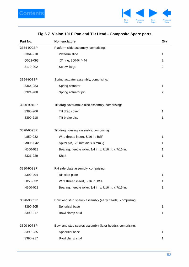
Fig 6.7 Vision 10LF Pan and Tilt Head - Composite Spare parts
Part No. Nomenclature Qty
3364-900SP Platform slide assembly, comprising:
3364-210 Platform slide 1
Q001-093 ‘O’ ring, 200-044-44 2
3170-202 Screw, large 2
3364-908SP Spring actuator assembly, comprising:
3364-283 Spring actuator 1
3321-280 Spring actuator pin 2
3390-901SP Tilt drag cover/brake disc assembly, comprising:
3390-206 Tilt drag cover 1
3390-218 Tilt brake disc 1
3390-902SP Tilt drag housing assembly, comprising:
L850-032 Wire thread insert, 5/16 in. BSF 1
M806-042 Spirol pin, .25 mm dia x 8 mm lg 1
N500-023 Bearing, needle roller, 1/4 in. x 7/16 in. x 7/16 in. 1
3321-229 Shaft 1
3390-903SP RH side plate assembly, comprising:
3390-204 RH side plate 1
L850-032 Wire thread insert, 5/16 in. BSF 1
N500-023 Bearing, needle roller, 1/4 in. x 7/16 in. x 7/16 in. 1
3390-906SP Bowl and stud spares assembly (early heads), comprising:
3390-205 Spherical base 1
3390-217 Bowl clamp stud 1
3390-907SP Bowl and stud spares assembly (later heads), comprising:
3390-235 Spherical base 1
3390-217 Bowl clamp stud 1
53
ContentsPrevious
PageFirst Page
Next Page
Previous View
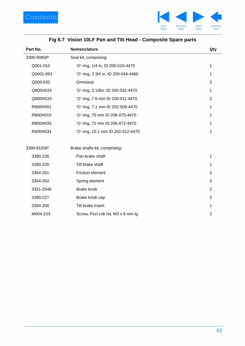
3390-908SP Seal kit, comprising:
Q001-010 ‘O’ ring, 1/4 in. ID 200-010-4470 1
Q0001-093 ‘O’ ring, 3 3/4 in. ID 200-044-4460 1
Q500-032 Omniseal 2
Q900H024 ‘O’ ring, 3 1/8in. ID 200-532-4470 1
Q900H033 ‘O’ ring, 7.6 mm ID 200-011-4470 2
R900H001 ‘O’ ring, 7.1 mm ID 202-509-4470 1
R900H010 ‘O’ ring, 75 mm ID 206-075-4470 1
R900H033 ‘O’ ring, 72 mm ID 206-072-4470 1
R900H034 ‘O’ ring, 10.1 mm ID 202-512-4470 1
3390-910SP Brake shafts kit, comprising:
3390-226 Pan brake shaft 1
3390-220 Tilt brake shaft 1
3364-351 Friction element 2
3364-352 Spring element 2
3321-2548 Brake knob 2
3390-227 Brake knob cap 2
3364-256 Tilt brake insert 1
M004-103 Screw, Pozi csk hd, M3 x 8 mm lg 2
Fig 6.7 Vision 10LF Pan and Tilt Head - Composite Spare parts
Part No. Nomenclature Qty