Embed Size (px)
Citation preview

1
CONTENTS
DECLARATION OF CONFORMITY 4THANK YOU FOR USING THIS KLARK TEKNIK PRODUCT 6AFTER YOU HAVE UNPACKED THE UNIT 7DN8000: Overview. 8DN8000: Signal Path Flow Chart. 10DN8000: Main Screen Display. 11
EDIT MENU: OVERVIEW 12The structure in full. 12Edit Menu: The Three Parameter Lists. 14
Main Parameters List. 16Master Delay Input A. 16Master Delay Input B. 16Source Selection. 16Output Delay. 17Polarity. 17Phase Adjust. 17Output Level. 17Output Label. 18
EQ Parameters List. 19High Pass Filter Frequency. 19High Pass Filter Response. 19High Pass Filter Peak. 20Low Pass Filter Frequency. 20Low Pass Filter Response. 20Parametric Filter One Frequency. 22Parametric Filter One ‘Q’. 22Parametric Filter One Level. 22Parametric Filter Two Frequency. 22Parametric Filter Two ‘Q’. 23Parametric Filter Two Level. 23Low EQ Filter Frequency. 23Low EQ Filter Q/Slope. 24Low EQ Filter Level. 24High EQ Filter Frequency. 24High EQ Filter Slope. 25High EQ Filter Level. 25

2
Dynamics Parameter List. 26Compressor Threshold. 26Compressor Ratio. 27Compressor Attack. 27Compressor Release. 27Gate Threshold. 28Gate Range. 28Gate Decay Rate. 28Limiter Threshold. 29
Options Menu Overview 30Limit Threshold Units. 30Compressor Threshold Units. 30Compressor Link. 31Output Meter Units. 31Meters Peak Hold. 31Delay Units. 32Delay Temperature Compensation. 32Clip/Limit Log. 32Maximum Output Level. 33Modify User List. 33Which List. 35Lockout PIN. 35Unlock. 36External Communications Channel. 37User Memory Protection. 37Memory Dumps. 38Power On Mute Delay. 41LCD Contrast. 41LED Brightness. 41Help Information. 42Software Version. 42Engineer Profiles 42
Connecting DN8000's For External Comms 45Remote Control. 45
Memory Access - Overview 46Memory Recall. 47Memory Save. 48OEM Pre-sets. 51
Additional Notes. 54Compressor Linkage. 54
3
Compare Function. 54Single Memory Reset. 57Editing Memory Names. 57Mute Switches. 57Analogue to Digital Converter Card & Input Level Control. 58Battery Low Warning. 59Three Dimensional Metering. 60Pot / Mute Behaviour in Lock Modes. 61Quick Lock. 62Generic Presets and Settings Tables. 62New Presets For Version 1.16. 62
Technical Specification. 72
Service Information. 73
4
DECLARATION OF CONFORMITY
The Directive Covered by this Conformity
89/336/EEC Electromagnetic Compatibility Directive, amended by 92/31/EEC & 93/68/EEC.73/23/EEC Low Voltage Directive, amended by 93/68/EEC.
The Products Covered by this Declaration
Equipment Type Product Name VariantsGraphic Equaliser DN300 DN360, DN301, DN332Preset Equaliser DN320 DN330Parametric Equaliser DN405 DN410Dynamics Processor DN500 DN504, DN510, DN514Audio Analyser DN6000Crossover DN800Delay Line DN7204 DN7103Programmable Equaliser DN3600 DN3601Remote Control System DN3698 DN3603Crossover DN8000Programmable Equaliser DN4000
The Basis on which Conformity is being Declared
The Products named above and hence the Variants thereof listed above comply with the require-ments of the above EU directives by meeting the following standards:EN 50081-1 (EN55022 class B)EN 50082-1 (IEC801 Part 2, 4 / ENV 50140 / ENV 50141EN 60065.
Signed: ........................... N. G. TembeAuthority: Head of Engineering, EVI Audio (U.K.) PlcDate: 1st January 1997
Attention!The attention of the specifier, purchaser, installer or user is drawn to the special limitations touse which must be observed when these products are taken into service to maintain compliancewith the above directives. Details of these special measures and limitations to use are availableon request, and are also contained in product manuals.

5
Attention!
Cables:This product should only be used with high quality, screened twisted pair audio cables, termi-nated with metal bodied 3-pin XLR connectors. The cable shield should be connected to pin 1.Any other cable type or configuration for the audio signals may result on degraded performancedue to electromagnetic interference.
Electric Fields:Should this product be used in an electromagnetic field that is amplitude modulated by an audiofrequency signal (20Hz to 20kHz), the signal to noise ratio may be degraded. Degradation of upto 60dB at a frequency corresponding to the modulation signal may be experienced under ex-treme conditions (3 V/m, 90% modulation).
No permanent damage or degradation of performance will be caused by these conditions.

6
THANK YOU FOR USING THIS KLARK TEKNIK PRODUCT
To obtain maximum performance from this precision electronic product, please study theseinstructions carefully. Installation and operating the DN8000 is not complicated, but theflexibility provided by its operating features merits familiarisation with it's controls andconnections. This unit has been prepared to comply with the power requirements that exist inyour location.
Precautions
Before connecting the unit to the mains power, ensure that the operating voltage is correctfor your local supply. Operating voltage is indicated on the rear panel.
Do not install this unit in a location subjected to excessive heat, dust or mechanical vibrations.
Power Connection
Connection is made by means of an IEC standard power socket. The unit will operate off anyAC voltage between 100 Vac and 240 Vac @ 50 Hz to 60Hz.
Before connecting this unit to the mains supply, ensure that the fuse fitted is the correct typeand rating, as indicated on the rear panel, adjacent to the fuse holder.
Safety Warning
This unit is fitted with 3-pin power socket. For safety reasons the earth lead should not bedisconnected.
To prevent shock or fire hazard, do not expose the unit to rain or moisture.
To avoid electrical shock, do not remove covers. Dangerous voltages exist inside. Referservicing to qualified personnel only.

7
AFTER YOU HAVE UNPACKED THE UNIT
Save all the packing materials - they will prove valuable should it become necessary totransport or ship this product.
Please inspect this unit carefully for any signs of damage incurred during transportation. It hasundergone stringent quality control inspection and tests prior to packing and left the factoryin perfect condition.
If, however, the unit shows any signs of damage, notify the transportation company withoutdelay. Only you, the consignee, may institute a claim against the carrier for damage duringtransportation.
If necessary, contact your supplier or as a last resort, your Klark Teknik importing agent, whowill fully co-operate under such circumstances.

8
DN8000: OVERVIEW
The DN8000 is a two input, five output digital crossover. Being a box of DSP, it has thepotential to fulfil not only the normal tasks thought of as applicable to a crossover, (i.e.frequency splitting) but many others. This allows it to replace much of, if not all of, theadditional outboard processing that has come to be associated with complete multi-driverspeaker system alignment and protection.
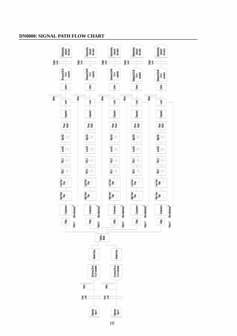
The unit is completely configurable from the front panel, and included in the signal path foreach input to output are the following modules. These modules are fixed in terms of theirposition in the path - their order has been optimised for the intended application as acrossover.
A delay module - this allows delays to be set for eachoutput, andmaster delays to be applied to each input. The unitsare selectable, and temperature compensation maybe added.
A fully configurable routing module - this allows any output to be fed from either input,both inputs or neither input.
A high pass filter module - this has fully variable frequency adjustment, and aselection of roll-off (slope) and filter typecombinations.
A low pass filter module - this has fully variable frequency adjustment, and aselection of roll-off (slope) and filter typecombinations.
Two parametric equaliser modules - these both feature fully adjustable frequency, ‘Q’,and level, and can be placed anywhere on thefrequency scale.
A 'Low EQ' filter module - this has variable frequency adjustment, and aselection either parametric mode or shelf mode, andlevel adjustment.
A 'High EQ' filter module - this has variable frequency adjustment, and aselection either parametric mode or shelf mode, andlevel adjustment.

9
A compressor module - this is fully featured, with adjustment available forthreshold, ratio, attack, and release.
An expander module - this has adjustment for threshold, hold and release.
A limiter module - this merely has adjustment of threshold. It is a 'zeroovershoot' design - and cannot be switched out ofcircuit. As such, it will not be possible to clip any ofthe outputs, no matter how much EQ has beenadded.
A phase control module - this allows the phase to be reversed (switch) andalso the phase angle to be adjusted in 5° steps.
A level control module - this allows adjustment of the level of the outputover a wide range.
The order of these modules is shown in the signal flow diagram overleaf.
10
DN8000: SIGNAL PATH FLOW CHART

11
DN8000: MAIN SCREEN DISPLAY.
The default screen will show the memory name and basic crossover construction. This willtake the form of routing information - the band designation will be apparent by the labelsilluminated over each output section. A typical display would be...
ABBA WEMBLEY #01 1A 2A 3B 4B 5 å
From this, it easy to see that outputs one and two are fed from input A, three and four frominput B, and five is fed from both (‘å ’ or both).To designate a feed from neither input an ‘-’ will be used.
Names can be up to 12 characters long for user memories, and 16 characters for OEM pre-sets.
Each of the output level controls on the front panel has a press action momentary switch.This is to allow quicker navigation around the edit screens, as the list of parameters availablefor adjustment is extensive. An additional feature of the output select switches is to givemore information regarding each output when the main screen is displayed.
Pressing an output select will show the routing information and the frequency range coveredby that output. For example, output 1 for the above set-up might display...
1:From:A ;-6dB 120Hz-3500Hz
...and output 5, designated as the mono bass output might display...
5:From:A+B; 0dB 20Hz-120Hz

12
EDIT MENU: OVERVIEW
The order and number of parameters can be adapted to suit the user to some extent throughthe use of the user parameter list as described elsewhere in this document. However, therewill be many cases when this list is not sufficient and all the parameters may need to be acces-sible.
The structure in fullThe editing on the DN800 has been split into three sub-sections - these and their contents areoutlined below:
Main- DelaySource (Routing)PhaseOutput LevelLabel (Front Panel Icon)
EQ- High PassLow PassPEQ 1PEQ 2Low EQHigh EQ
Dynamics- CompressorExpanderLimiter
When edit is pressed and the “Which List?” option is set to “All”, an initial help screen ap-pears as below for a few seconds. It is worth noting that with any help screen that onlyappears once when a button is pressed, the user does not have to wait until the help disap-pears to continue. Once familiar with the user interface, he/she can either disable the extrahelp or just press/turn what is known to be the next operating step. This action will automati-cally clear the help and continue.
Edit Mode: PressAgain to Exit!
followed by….
MAIN eq dynEncoder=Choose

13
with the bottom line toggling to show...
MAIN eq dyn <SELECT>=Begin
...every two seconds.
The idea here is that the encoder will choose a sub-list to start editing, and pressing a selectkey will enter that list immediately. The encoder will show which list is going to be enteredon a press of a ‘select’ button by displaying the chosen list title in upper case, i.e.
MAIN eq dyn Encoder=Choose
or
main EQ dyn Encoder=Choose
or
main eq DYN Encoder=Choose
So, with ‘MAIN’ written in upper case, pressing a select button will enter the main parameterediting list which comprises:
master delays,routing,output delay,phase,output level,label.

14
Similarly, with ‘EQ’ the list for equalisation editing is entered directly, comprising the sec-tions:
high pass,low pass,PEQ 1,
PEQ 2,
low EQ,
high EQ.Lastly, with ‘DYN’ the list for dynamics editing is entered directly, comprising the sections:
compressor,expander,limiter.
At any of the three stages above, the select buttons will now scroll round the list of param-eters in the selected sub-list only. If a different list is to be selected, pressing edit twice (toexit the mode and re-enter at the list choice stage) allows this to be accomplished quickly.Note that the ENTER key can also be used to scroll round the main/EQ/dynamics headings.
The last selected parameter in all three lists will be remembered (as will the last selectedparameter in the user list, if chosen in the options menu), so that when a list is re-enteredediting can carry on as before. When edit is initially pressed, before selecting a list, the choiceof list always defaults to ‘MAIN’.
A compare feature is available when editing. Please read the section entitled "Compare Func-tion" in the additional notes towards the back of this manual.
Edit Menu: The Three Parameter Lists.
The structure and operation of the lists has been covered in sufficient detail now to allow thecontents of the lists to be examined and detailed at the bottom level. The descriptions willtake the form of a screen shot with the range of each parameter given, along with any addi-tional points where necessary.
Worth a mention at this stage is the use of the output level controls ‘press to select’ action.Their main function is, when editing, to allow selection of each output for adjustment. Theidea of scrolling through a parameter with five outputs - e.g. PEQ1 Frequency Output 1,PEQ1 Frequency Output 2 etc. has been avoided. The select switches will select the nextparameter, NOT scroll through the five outputs at one parameter.
Selected Output IndicationAlthough it will be displayed on the screen as an icon during edit mode, when an output isselected, its label in the associated window will begin to flash.

15
Warning: Default Parameter Values.
Please note that when the unit leaves the factory, it will have had all its memories,including the working memory loaded upon power-up, set to default values. As usersettings cannot be predicted (unless a specific OEM preset has been requested) thesesettings have been chosen to minimise the risk of damage to loudspeaker systems uponfirst connection. However, it is strongly recommended that initially no audioconnections are made to the unit due to the fact that
NO CROSSOVER FILTERS ARE IN PLACE WHEN POWER IS APPLIED FORTHE VERY FIRST TIME.
The high and low pass filters should be introduced as appropriate prior to adjustinggain, routing, or dynamics parameters. These have all be set to minimise output levelregardless of input level.

16
Main Parameters List.
Master Delay Input A.
EDIT :Master Del 1300000 us
Range: 2ms to 1300msNotes: Total delay for each input to output is 1300ms max.
Master Delay Input B.
EDIT :Master Del 1100000 us
Range: 2ms to 1300msNotes: Total delay for each input to output is 1300ms max.
Source Selection.
EDIT :Source Input A [A]
Range: A, B, A+B, Off.Notes: These are displayed as ‘A’, ‘B’, ‘å ’, and ‘-’ respectively on the main
screen.Available sources will depend on the master / output delay combination.

17
Output Delay.
EDIT :Output Del 4456 uS
Range: 2mS to 300mS
Notes: This is dynamically allocated from the 1300mS pool available for use withthe master delay.
Polarity.
EDIT :Polarity Reversed
Range: Normal/Reversed
Phase Adjust.
EDIT :Phase Adj 125°
Range: 0 to 180°
Notes: 5° steps
Output Level.
EDIT :Output Lvl -12dB

18
Range: +24dB to -40dBNotes: The entire range of adjustment is only available using the combination of
encoder and trim pot. Turning the trim pot will move the window of controlavailable, and will update the level parameter on the screen in real time. Ifthe output has been muted with, shockingly enough, the mute switch thenthe display will still allow adjustment of the level but will also show...
EDIT :Output Lvl MUTE -12dB
Output Label.
EDIT : Label Sub
Range: Sub, Lo, Lo-Mid, Mid, Hi-Mid, Hi, Full-Range, None.
Notes: As the selection is changed, the icon on the front panel will be seento change in sympathy.

19
EQ Parameters List.
High Pass Filter Frequency.
EDIT :HPF:Freq. 15000 Hz
Range: 20Hz to 15000Hz
High Pass Filter Response.
EDIT :HPF:Resp. Lnk-Ril 24dB/Oct
Range: Exact Text Shown... Full Range (Off)
6dB/OctBessel 12dB/OctButter 12dB/OctLnk-Ril 12dB/OctPeaking 12dB/OctBessel 18dB/OctButter 18dB/OctBessel 24dB/OctButter 24dB/OctLnk-Ril 24dB/OctPeaking 24dB/OctBessel 36dB/OctButter 36dB/OctLnk-Ril 36dB/OctBessel 48dB/OctButter 48dB/OctLnk-Ril 48dB/Oct
Notes: To protect individual system components, if the ‘Full Range’ selection ischosen, the selected output will mute. This mute can be turned offmanually, but will always be automatically enabled.

20
High Pass Filter Peak.
EDIT :HPF:Peak 2 dB Lift
Range: 0dB to 6dB
Notes: This is the under-damping of the filter to allow extra emphasis at the cornerfrequency without the need for a separate filter. This parameter is onlyadjustable if the high pass filter response type is set to a “Peaking” type.Under all other circumstances the lift applied is fixed at 0dB. This isreflected in the display by showing...
EDIT :HPF:Peak 0 dB [Set]
The setting of the lift, when applied to peaking type filters, however, will beremembered.
Low Pass Filter Frequency.
EDIT :LPF:Freq. 1250 Hz
Range: 50Hz to 20000Hz
Low Pass Filter Response.
EDIT :LPF:Resp. Lnk-Ril 24dB/Oct

21
Range: Exact Text Shown... Full Range (Off)
6dB/OctBessel 12dB/OctButter 12dB/OctLnk-Ril 12dB/OctBessel 18dB/OctButter 18dB/OctBessel 24dB/OctButter 24dB/OctLnk-Ril 24dB/OctBessel 36dB/OctButter 36dB/OctLnk-Ril 36dB/OctBessel 48dB/OctButter 48dB/OctLnk-Ril 48dB/Oct
Notes: To protect individual system components, if the ‘Full Range’ selection ischosen, the selected output will mute. This mute can be turned off manually,but will always be automatically enabled.

22
Parametric Filter One Frequency.
EDIT :PEQ1:Freq. 1250 Hz
Range: 20Hz to 20000Hz
Parametric Filter One ‘Q’.
EDIT :PEQ1:'Q' 2.5 Oct.
Range: 0.08; 0.01-1.0 (0.1 steps); 1.2; 1.5; 2.0; 2.5; 3.0
Notes: Called ‘Q’, but displayed in octave bandwidth.
Parametric Filter One Level.
EDIT :PEQ1:Level +3.5dB
Range: -12 to +12dB in 0.5dB steps
Parametric Filter Two Frequency.
EDIT :PEQ2:Freq. 1250 Hz
Range: 20Hz to 20000Hz

23
Parametric Filter Two ‘Q’.
EDIT :PEQ2:’Q’ 2.5 Oct.
Range: 0.08; 0.1-1.0(0.1 steps); 1.2; 1.5; 2.0; 2.5; 3.0
Notes: Called ‘Q’, but displayed in octave bandwidth.
Parametric Filter Two Level.
EDIT :PEQ2:Level +3.5dB
Range: -12 to +12dB in 0.5dB steps
Low EQ Filter Frequency.
EDIT :LEQ:Freq 100Hz
Range: 20Hz to 1000 Hz

24
Low EQ Filter Q/Slope.
EDIT :LEQ:Q/Slpe 12dB/Oct [LoShf]
Range: 'Q' as for parametrics, 6 or 12dB/Octave for shelf
Notes: This filter is switchable between a parametric and a shelf by turning theencoder one step above the widest 'Q' setting. This converts it to a shelvingresponse with selectable slope.
Low EQ Filter Level.
EDIT :LEQ:Level +3.5dB
Range: -12dB to +12dB in 0.5dB steps
High EQ Filter Frequency.
EDIT :HEQ:Freq. 12500Hz
Range: 500Hz to 15kHz

25
High EQ Filter Slope.
EDIT :HEQ:Freq. 12dB/Oct.
Range: 'Q' as for parametrics, 6 or 12dB/Octave for shelf
Notes: This filter is switchable between a parametric and a shelf by turning theencoder one step above the widest 'Q' setting. This converts it to a shelvingresponse with selectable slope.
High EQ Filter Level.
EDIT :HEQ:Level +3.5dB
Range: -12dB to +12dB in 0.5dB steps

26
Dynamics Parameter List.
Note: When any parameter relating to the compressor is being edited, the output metersautomatically change mode to show the amount of gain reduction being applied. This readsfrom the top of the meter (red LED) downwards. The front panel scaling is still accurate, sofor example if the red LED and both yellow LEDs are illuminated, 9dB of gain reduction isbeing applied to that output.
Compressor Threshold.
EDIT :Comp:Thr. -10dBu
Range: -10dBu to +22dBu
Notes: The units used are adjustable in the options menu, and may be set toabsolute (dBu), dB from clipping point, or dB from the limiter threshold.Confirmation of the selected units is by additional text as shown. For dBfrom clipping the display shows.
EDIT :Comp:Thr. [Clp]-10dB
EDIT :Comp:Thr. [Lim] 10dB
and for dB from the limiter threshold,
27
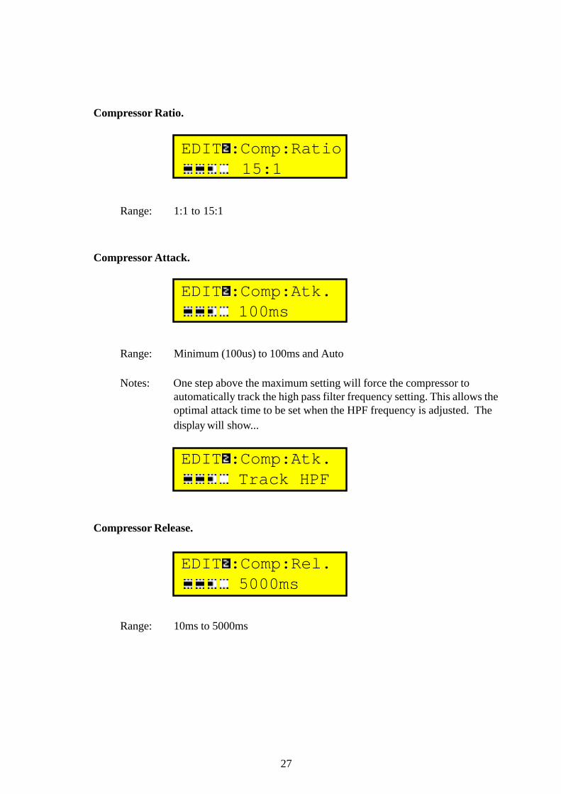
Compressor Ratio.
EDIT :Comp:Ratio 15:1
Range: 1:1 to 15:1
Compressor Attack.
EDIT :Comp:Atk. 100ms
Range: Minimum (100us) to 100ms and Auto
Notes: One step above the maximum setting will force the compressor toautomatically track the high pass filter frequency setting. This allows theoptimal attack time to be set when the HPF frequency is adjusted. Thedisplay will show...
EDIT :Comp:Atk. Track HPF
Compressor Release.
EDIT :Comp:Rel. 5000ms
Range: 10ms to 5000ms

28
Gate Threshold.
EDIT :Gate:Thr. -80dBu
Range: -80dB to -10dB
Gate Range.
EDIT :Gate:Range 25dB
Range: 0dB to 70dB
Note: The range sets the level of attenuation when the gate is closed. If this is setto 0dB, the gate is effectively turned off, and this is reflected in the display...
EDIT :Gate:Range 0dB [Off]
Gate Decay Rate.
EDIT :Gate:Decay 0.03dB/ms
Range: 0.01dB.ms to 0.1dB/ms in 0.01dB/ms steps, then
0.1dB/.ms to 2.0dB/ms in 0.1dB/ms steps.
Note: This parameter sets the speed at which the gate approaches its closedattenuation setting. As such, the rate and the range are interrelated.

29
Limiter Threshold.
EDIT :Limit:Thr. -4dBu
Range: -10 to +22dBu
Notes: Set at +22dBu limiter is NOT effectively off.The units used are adjustable in the options menu, and may be set toabsolute (dBu), or dB from clipping point. Confirmation of the selectedunits is by additional text as shown. For dB from clipping the display shows
EDIT :Limit:Thr. [Clp]-10dB

30
Limit Threshold Units.
Limit Threshold in dB from Clip
Range: dBu; Volts; dB from Clip
Notes: Range available when readout is in Volts is determined by the “Max OutputLevel” parameter above.
Compressor Threshold Units.
Compressor Thd.in dB from Limit
Range: dBu; dB from Limit; dB from Clip
Notes: Range available will be related to the limiter threshold when readout is setto “dB from Limit”.
Options Menu Overview
The options menu contains all the miscellaneous user adjustable parameters not directlyrelated to audio (on an output by output basis), and therefore not stored in individualmemories.
Pressing Options will display a brief screen of help text before entering the list of availableoptions. As usual, the list will be re-entered where it was last left. So, the help screen is...
Options:Press Again to Exit!
...followed by, starting at the beginning of the list...
31
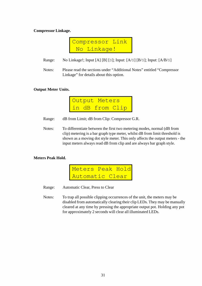
Compressor Linkage.
Compressor Link No Linkage!
Range: No Linkage!; Input [A] [B] [S]; Input: [A/S] [B/S]; Input: [A/B/S]
Notes: Please read the sections under “Additional Notes” entitled “CompressorLinkage” for details about this option.
Output Meter Units.
Output Metersin dB from Clip
Range: dB from Limit; dB from Clip: Compressor G.R.
Notes: To differentiate between the first two metering modes, normal (dB fromclip) metering is a bar graph type meter, whilst dB from limit threshold isshown as a moving dot style meter. This only affects the output meters - theinput meters always read dB from clip and are always bar graph style.
Meters Peak Hold.
Meters Peak HoldAutomatic Clear
Range: Automatic Clear, Press to Clear
Notes: To trap all possible clipping occurrences of the unit, the meters may bedisabled from automatically clearing their clip LEDs. They may be manuallycleared at any time by pressing the appropriate output pot. Holding any potfor approximately 2 seconds will clear all illuminated LEDs.

32
Delay Units.
Delay Units AreMetric
Range: Time(us); Time(ms); Metric; Imperial
Notes: The minimum increment in microseconds is 21us.
Delay Temperature Compensation.
Delay Temp. Compensate: 32°C
Range: 0 to +40°C
Notes: If the previous option has set the units to read out in time rather thandistance, the temperature compensation is fixed at +20°C. This state isreflected on the display as…
Delay Temp. [Set] Compensate: 20°C
Clip/Limit Log.
The clip log counts how many times the input meters and output meters hit maximum overtime. The time is stored in memory so that it continues from its last value when the unit isnext switched on.
Initially the display shows...
Clip/Limit Log:Encoder = Check
...and turning the encoder will cycle through…

33
Log Time:003 HrsIns [A/B]:0000345
Maximum Output Level.
Max Output Level2.45V:Power Amps
Range: 2.45V:Power Amps; 9.75V:Line Drive
Notes: Changing this setting switches a 12dB pad into all the outputs. This pad ispurely analogue and is switched to match the input sensitivity accuratelywhen driving power amplifiers. When the limiter units have been set to readout in Volts, this setting will affect the range available.
Modify User List.
As mentioned earlier, the number of parameters available for adjustment on each output islarge (at the last count, 33 in total) and scrolling through this list can be tedious and timeconsuming, even given the output select controls.
This option is available for the user to select up to ten of the most used parameters and createa ‘user’ parameter list. If this list is selected, under the ‘Which List’ option, when the editmode is enabled, only the user selected parameters will appear in the list. So for example,once the crossover points and EQ have been selected, the only parameters that need to be inthe user list might be, delay time, phase adjust, level and limiter threshold.
Selecting this option now will display...
Modify User ListOutput Lvl: ___
...with the option to add or delete this item being immediately available.
This has been achieved by displaying, as above ‘___’ if the parameter is not in the list, and...
Modify User ListOutput Lvl: USER

34
...if the parameter is in the list. The top line of help text will automatically begin togglingwhen the option if selected using the select keys, but the information will be related as towhether the parameter shown is already in the list or not. Just like this…
Modify User ListOutput Lvl :___
...will toggle to...
ENTER = Add![04]Output Lvl :___
The number in square brackets indicates how many parameters may still be added to the list.For a parameter already in the list, the top line will show...
ENTER = Delete!Output Lvl :USER
Pressing enter will still toggle the selected parameter to include it or exclude it from the list,with the accompanying text updating to the right of it.
If ten parameters have been selected, and another is chosen to be added to the list, rather thanautomatically delete one already in the list (which would take some working out by the useras to which end of the list was being attacked) a message is displayed as below on the topline...
10 Item Limit!Output Lvl :USER
...toggling with...
Modify User ListOutput Lvl :USER
...if the item currently selected is in the list, or...

35
ENTER = Delete!Output Lvl :___
if not.
The user then has to go back through the list and delete some parameters if different ones areto be added.
Which List.
Coupled with the construction of the user parameter list, is the selection of which list to use -the user list or the full list. This is simply selected as below. The display shows…
Which List?All Parameters
or
Which List?User Parameters
If a preset is currently being used, unless the PIN for the preset has been correctly entered,the choice will not be available. Under these circumstances the display will show
Which List?OEM Parameters
Note that if the user list has been emptied, this option automatically switches to “All Param-eters”, and it will not be possible to select the “User Parameters”.
Lockout PIN.
The security lockout allows the user to prevent unwanted tampering with the front panel attwo levels. The full lockout disables all control, the partial lockout allows memory recall andpreview access and use of the mute switches and pots.
The user is expected to select a five digit number to use as the PIN. Initially this will be

36
displayed as ‘None’, but once the encoder is used to advance this number, the lockoutbecomes partially armed and pressing the ‘Enter’ button will display a question as to whetheror not memory recalls are to be allowed in the lockout mode, as below. Help is provided onthe way, as below,
Lockout PIN ...Select No.:None
...and then…
Lockout PIN ...Select No.:
Pressing Enter will then display…
Allow RecallsWhen Locked? No
The encoder will obviously choose yes or no and at this point in the proceedings pressingEnter will now lock the unit with the chosen PIN. The display will briefly show…
Unit is Locked!Options = Unlock
… before reverting to the normal main screen display. Note that it is possible to lock the unitwith no PIN, if required. Now, pressing any other button, apart from Options, or turning theencoder will display the “Unit is Locked!” message. If the lockout has been set to allowmemory recalls, turning the encoder will still scroll through the memories, and the Enterbutton will still be active. All other buttons will do nothing.
Unlock.
Pressing Options will show…
Lockout PIN ...Select No.:None

37
and then pressing Enter will either display…
PIN Accepted,Unit Unlocked!
… if code was correct, followed by normal main display and operation, or...
PIN Incorrect,Unit Locked!
… if the code was wrong, followed by the normal main display, and the same scenario asabove if anything is pressed or turned. See additional section regarding pot/mute access inlock mode - only for version 1.16.
External Communications Channel.
External CommsChannel : 1
Range: 1 to 32, "Receive Only"
Notes: Please read the section entitled “Memory Dumps…” for a full explanation.
User Memory Protection
It is possible to protect up to the first 30 user memories against being overwritten. This doesnot affect the ability to recall or edit the memories, it just prevents storing to their location.On entering this option, the screen looks like this:
Memory ProtectIs Off!
Turning the encoder now selects how many memories to protect, starting with the first up tothe 30th. The number of memories chosen are always in a contiguous block:
Memory ProtectFirst Mem Only

38
Memory ProtectFirst 2 Mems
up to:
Memory ProtectFirst 30 Mems
A protected memory is signified by the addition of exclamation marks around the signalrouting information:
ROD WEMBLEY #01!1A 2A 3B 4 å 5-!
The only time that these markings cannot be seen is when the memory is the last recalledmemory, then the markings become <>. Attempting to store to a protected memory is notpossible as protected memories are not accessible on pressing store.
Memory Dumps…
This option allows memories to be copied from another DN8000 to facilitate cloning of units.Please read the section entitled “Connecting DN8000’s for External Comms” beforeproceeding. Note the protocol in use with this system - the unit being adjusted requestssettings from the other unit - information is never transmitted manually to any unit. The unitto be copied from merely has to be switched on and connected to the destination unit viaeither RS485 socket on the back panel. Protection against inadvertent over-writing of settingsis of paramount importance in a system such as this and, to this end, the operation of thisoption has been made slightly more complex.
The initial display will show…
Memory Dumps ...None Requested!
… and it’s worth noting that this will always be the case if the options menu is excited by anymeans, or the option is re-selected within the menu. Turning the encoder will scroll throughthe available dump requests. These are…

39
Enter = RX Dump:User Memory #NN
...over the range of available user memories, followed by…
Enter = RX Dump:All User Mems
…which will include the working memory (i.e. the current configuration).
Lastly, the working memory may be requested on its own, like this…
Enter = RX Dump:Working Memory
Note that the range of memories that can be requested is related to the setting of the memoryprotection option. The protected memories cannot be requested (and therefore accidentallyover-written). Even when the “All User Mems” option is selected, the requests are confinedto the range First unprotected memory à Memory #32 and Working Memory.
Note that the unit must be set to the global external communication channel to transmit arequest. If it isn’t a warning is displayed when ENTER is pressed.
Enter = RX Dump:Comms Not Global
Otherwise, pressing ENTER will transmit a request for the settings indicated. If the otherunit is switched on and connected correctly, it will briefly display the message
Sending Mem DumpPlease Wait ...
before reverting to the default (power-up) mode.

40
The unit receiving the dump will show…
Receiving >>>:: #NN
...where NN is the number of the memory it’s for, and the colon beside the number denotesit’s waiting. This is relevant when a dump of more than one memory is requested. When theworking memory has been requested, the display shows...
Receiving >>>:: Wkg
In practise, the rest of the bottom line will not be blank for any appreciable time. When amemory has been completely received without error, the bottom line is updated with is name,and the colon disappears to indicate completion. Like this…
Receiving Done!ALL WEDGES #12
Reception of a single memory takes under a second, and it follows that reception of acomplete memory dump of all 32 memories and the working memory takes in the order of 30seconds. Both units are non-interruptible under these circumstances, and although memoriesare not over written until the replacement settings are checked, do not disturb either unitduring the dump procedure.
If there is a problem, and the receiving unit hasn’t received anything, the following happens:after pressing ENTER to request some settings the display changes to...
Awaiting Dump...___
The dashed line grows across the bottom line until the unit gives up (after 4 seconds) andshows…
Request Expired!Check Other Unit
…and then reverts to the request screen again. ENTER can be pressed immediately if theproblem has been fixed, without needing to re-select the request type.

41
Note that only two units can be connected together in this way - multiple units can be clonedat the same time, due to the protocol being used. But…if multiple units are connectedtogether full Remote Control is possible. See section entitled "Connecting DN8000s forexternal comms"
Power On Mute Delay
Power On MuteDelay: 5 Seconds
Range: None; 1 to 30 seconds in 1 second steps, and Permanent
Notes: ‘None’ means audio appearing as soon as the DN8000 has booted theDSPs, and ‘Permanent’ means that the mutes stay on until turned offmanually by the user. In the event of intermittent mains power failure whichmight result in large noise spikes in the audio, two spikes in quicksuccession will cause the unit to re-boot permanently muted to protect thesubsequent parts of the system (primarily the speakers).
During boot-up mutes that will be de-activated after the preset delay periodwill flash - the flash rate will double for the last 3 seconds to indicate theimminent state.
LCD Contrast.
LCD Contrast Adj +10
Range: -10 to +10
LED Brightness.
LED Brightness 14
Range: 1 to 14
Notes: This setting adjusts the brightness of all indicators, but not the back light ofthe LCD which is fixed at maximum.

42
Help Information.
Help InformationPatronisingly
Range: Patronisingly, Thoughtfully, Smugly
Notes: Patronisingly is all help messages, Thoughtfully is help only when something dangerous could happen, and Smugly is after something dangeroushas happened. The help message level affects many parts of the systemsoperation. Set to its minimum level, no initial messages occur when enteringstore, options or edit modes, and memory access times become unprotectedin both store and recall modes.
Software Version
Software Version1.16 - 01/04/98
Engineer Profiles
As the possibility exists for a variety of different engineers to be using a DN8000 over aperiod of time, and given the multitude of customisable options available to personalise theunits operation, it is now possible to set up a profile for up to six different users, and instantlyreset the options menu to the engineers preferences. This is accomplished as described below.
There are two new entries at the end of the options menu list. The first of these is the
engineers name options.
ENTER=Edit Name!No User Name Set
Pressing EDIT will allow this name to be customised, in an identical manner to the user IDoption that it follows. The screen will briefly show...
Name This Set OfEng'r_Options...

43
...followed by a cursor appearing under the first character of the present name. The encoder isused to change the character, and the SELECT keys move the cursor. Pressing and holdingboth SELECT keys will reset the name to a default.
Edit This Name:No User Name Set
Pressing ENTER will accept this new name, with confirmation given by...
Engineers Name:WARING HAYES
This name is stored as part of the profile, and is used to select which profile to use. Thatchoice is made using the next option.
Choose Engineer:SIMON MOSS
Turning the encoder will scroll through the available user profiles - five are available inaddition to the one already in use. To avoid having separate store and recall procedures at thispoint, the method used is that the required profile is chosen and ENTER is pressed. This willbe confirmed by the chosen profile name appearing on the top line of the display like this...
SIMON MOSSOptions Active!
At this point the options menu will change to the settings stored with the profile name. Thecurrent set of options, along with the engineers name will replace (be swapped with) the setjust chosen. This will result in the list of engineers being open to reordering, but as there areonly five, it should not be confusing. Pressing ENTER again will swap the old profile back (ifthe encoder has not been moved).

44
Not all the items in the options menu are stored in a profile.Those that are, are listed below:
● The unit's ID name;● The engineer's name;● The LCD contrast;● The LED brightness;● The Delay units read-out;● The Delay temperature compensation;● The 12dB pad setting;● The Limiter Threshold units read-out;● The Compressor Threshold units read-out;● The Compressor Linkage mode;● The Output Metering mode;● The Output Metering peak hold behaviour;● The Power On Mute delay;● The Help System (User/All parameters);● The Number of Protected Memories;● The User List of Favourite Parameters.
For security reasons, all options concerned with communications, and lockout are not storedand always remain global. Additionally, loading a different set of options when the workingmemory contains a preset (with a predefined list of available parameters) will not overwritethe editable list for the preset (or preset copy) in use.
Once a set of user options (a profile) are in place, the message displayed upon entry to theoptions menu will detail which set of options are being used. Like this...
Options Set ForWARING HAYES

45
Connecting DN8000's for External Comms
Please note the following points before using the RS485 communications on the DN8000.
1) RS485 is a node based system - that is, no one unit on the line is a permanent masterand all units will receive all data as they merely tap off a common wire. This is thesameprinciple as Ethernet - the input and output sockets on the rear panel are linkedthrough in hardware. If a unit fails it will not disturb the communications to unitsfurther down the chain.
2) The units must be connected In to Out down the chain to the last unit. It does not needto be looped back to the first unit, if it is the system will not function correctly.
3) The first and last units in the chain must have their "Terminate" switches set to "ON"(i.e. in the direction of the arrow on the rear panel). All other units must have their"Terminate" switches set to "OFF". This follows the same convention as an Ethernetbased system. If this is not adhered to, reflections will occur along the transmissioncable, causing unpredictable results.
4) When cloning units or dumping memories, only two units can co-exist on the line at thesame time and on the same channel - the unit requesting the dump, and the unittransmitting the dump.
5) When units are connected together and switched on, all units on the same channel willassume the same parameter value if any unit is adjusted. As mentioned in the remotecontrol section of this manual, this is intentional, as the current protocol is designed fortwo connected units to operate as a four-input ten-output crossover as transparently aspossible.
Remote Control
This remote control extends to all the audio functions available in the EDIT menu, memoryrecalls, and memory stores, including the transmission of the chosen name. This mode is notreally designed for a chain of multiple units to be connected together, more for a pair of unitsto operate seamlessly as a four-input ten-output crossover. Connecting multiple units willwork, but adjusting a parameter on any unit will set it to the same value on all connectedunits. To operate in this mode, both units must have the same external communicationschannel. Either unit can assume the job of the master unit - it’s best to think of the two unitsas a single device as they are able to control each other at all times.In this way it can easily be determined that a change has been made.
RS-485 INPUTSOUT I/P B
O/P 5 O/P 4 O/P 3
OUTPUTS
O/P 2 O/P 1
IN TERMINATE I/P A
90-250V AC~50-60 Hz 30VA
FUSE 5 x 20mm T500mA / 250V
MADE IN ENGLAND
WARNING:THIS EQUIPMENT MUST BE EARTHED.

46
Memory Access - Overview
The structure of memory management has been implemented in such a way as to maximiseflexibility when editing. Edits are not performed direct to user memories - there is a scratchpad referred to as ‘working memory’.
Working memory is structured in the same way as a single user memory, and is therefore alsobattery backed. This has the advantage of retaining edits on power down, and being able tocontinue with them on power up.
User memory is recalled into working memory where it can then be edited and subsequentlystored. However, as soon as working memory is edited (and is therefore different to itsoriginal recalled version), the name of the memory changes to lower case:
abba wembley #01 1A 2A 3B 4B 5-
If all changes are undone (e.g. mute on/off/on) the memory name reverts back to upper caseto indicate that working memory is now the same as the user memory from which it wasrecalled:
ABBA WEMBLEY #01 1A 2A 3B 4B 5-

47
Memory Recall.
Typically the main screen will be similar to:
ABBA WEMBLEY #01 1A 2A 3B 4B 5-
Turning the encoder on this screen will scroll through the memories, updating the top line ofthe screen with the memory name and number, and the bottom line with its signal routingdetails:
ROD WEMBLEY #05 1A 2A 3B 4 - 5-
This screen will alternate with the message:
Press and hold ENTER to recall
Additional information about the memory may be obtained by pressing the output selectbuttons on the front panel. This will display the output’s routing information, and both itshigh and low pass frequency settings:
1:From:A ; 0dB 20Hz-350Hz
Note that if an output is assigned to ‘-’ (nothing) the display is:
5:No Input; 0dB 20Hz-350Hz

48
Once the memory to be recalled has been decided, this is confirmed by pressing and holdingENTER, as in the alternating message. This begins a countdown displayed as a decaying bargraph.
Ready to recall: Hold key!
The bar decays as long as the ENTER key is held. The speed of this decay is determined bythe help level, and the result of the memory compare algorithm. If the memory to be recalledis sufficiently different to the working memory, the hold time may reach a maximum value.This will result in ‘hold’ being displayed in upper case letters to indicate this:
Ready to recall: HOLD key!
If ENTER is released without the bar graph decaying to zero, the recall is effectively aborted,and the screen displays:
Recall has been aborted!
If ENTER has been held and the bar graph decays to zero, the memory is then recalled:
Recalling... Hold key!
NOTE:
The last memory to be recalled is indicated by the use of <> to encapsulate the output detailsas below:
ROD WEMBLEY #05 <1A 2A 3B 4 å 5->

49
Memory Save.
Pressing store initially displays:
Store Mem:Press Again to Exit!
...followed by...
Store to Memory ABBA WEMBLEY #01
...which alternates with...
Press ENTER to accept location
The list of memory names can be scrolled through to choose the location and then, if ENTERis pressed the message changes to...
Store = Confirm! ABBA WEMBLEY #01
...with a cursor below the first letter of the name, allowing it to be changed using the encoderto select the character, and the select keys to move the cursor.
Pressing store will display:
Ready to store: Hold key!

50
If the memory to be recalled is sufficiently different to the working memory, the hold timemay reach a maximum value. This will result in ‘hold’ being displayed in upper case letters toindicate this:
Ready to store: HOLD key!
If STORE is released without the bar graph being fully reduced, the store is effectivelyaborted, and the screen displays:
Store has been aborted!
If STORE has been held and the bar graph decays to zero, the memory is then stored:
Storing... Hold key!
NOTE:
The last memory to be stored is indicated by the use of >< to encapsulate the output details asbelow:
ROD WEMBLEY #05 >1A 2A 3B 4 å 5-<
The only time that these markings do not appear is when the memory is protected, then theybecome ‘!!’.

51
OEM Pre-sets
These are memories that have been pre-set by speaker manufactures to optimise settings fortheir own systems. OEM pre-sets are located at the end of the memories i.e., they start atmemory 32 and work up. The pre-sets are easily identified from their name because they donot have memory numbers - their names can be up to 16 characters long instead. In additionto this, when recalling a pre-set, the following message appears:
Recalling... ===OEM Preset===
then, the pre-set:
EV DS 4183 <1A 2A 3B 4 å 5->
A further degree of protection is added to pre-sets by the OEMs. Instead of being able to editall parameters as with user memories, editing is only from a list of parameters made availableby the OEM (similar to a user parameter list). This can be seen in the options menu, andcannot be readily changed:
Which List? OEM Parameters
This is the only option for which list. Modification of this list is protected with a pass codesupplied by the OEM:
Modify User List Access No.:None!

52
alternating with:
Access Denied! Access No.:None!
Turning the encoder increments a number to select the code. When the correct code has beenreached, press ENTER to accept it. The list will then be editable.

53
This page has been left blank intentionally.

54
ADDITIONAL NOTES.
Compressor Linkage.
To prevent dynamic shifts in either the stereo image or the frequency response of the system,it is possible to link the side-chains of the compressors together. This is accomplished throughthe options menu - see the earlier operational description for details. There are four modesavailable and setting a particular mode will affect all five outputs at the same time. Theseimplement various types of intelligent linkage and may be thought of as follows.
Mode 1 - "No Linkage!". This is self explanatory - all five compressors are completelyindependent in their operation.
Mode 2 - "Input:[A] [B] [å ]". This mode links the side-chains of all outputs that are fedexclusively from an input. So if, for example, outputs 1 to 2 were fed from inputA, outputs 3 and 4 from B and 5 from the sum of A and B (å ), any exceededthreshold on outputs 1 to 2 may cause compression on both outputs. Similarly ifeither 3 or 4 compress, both may be affected. Compression on output 5 will notaffect any other output.
Mode 3 - "Input: [A/å ] [B/å ]". This mode links the side-chains of all outputs that are fedinclusively from an input. So if, for example , the same routing existed as in theabove example, the difference in operation would be at any compression onoutputs 1 to 4 may now affect output 5 as well, as it receives an input from bothA and B.
Mode 4 - "Input: [A/B/å ]". This mode links all the compressors together, regardless ofinput.The effect this has on the operation is that compression on any output mayaffect all the others.
Please note the fact that in all three linked modes, compression may be applied to all linkedoutputs, but the amount of "linked" gain reduction is dependant not only on the variousthresholds set, but also on the attack and release times of whichever compressor has exceededthe threshold the most. This intelligent linkage strives to make the action of the linkedcompressors as transparent as possible, provided the ratio used is not excessive. Arecommended maximum ratio for transparent operation is 5:1.
Compare Function.
During editing it is possible to swap between two complete unit configurations, to allowcomparisons to be made. The compare function is only active whilst in Edit mode and acompare is performed by pressing and holding the ENTER key. This will swap the current

55
The display will show one of several messages to alert the user that a compare has beenperformed. These detail the changes between the current configuration and the configurationbeing compared. If there are no changes at all - for instance after post a memory recall, thedisplay will show…
No Changes MadeTo Compare With!
….before reverting back to the parameter that was being edited.
If the compare memory is audibly identical to the working memory, the display will show….
Swapping-But NoAudible Changes!
This will be the case for the following where these changes will not affect the audible signalpath:
¨ Labels;¨ HPF/LPF frequency changes if the response is set to OFF;¨ PEQ frequency/’Q’ changes if the filter level is set to 0dB;¨ Low/High EQ filter frequency/slope changes if the level is 0dB;¨ Compressor attack/release/threshold changes if the ratio is set to 1:1;¨ Gate threshold/decay changes if the range is set to 0dB
If there are audible changes, the menus that these changes are in will be shown. For instance,if there are changes in output levels only, the display will show….
Swapping-ChangesIn Main Only!
….or if changes have been made to parametric filter settings and limiter thresholds have beenadjusted….
Swapping-ChangesIn EQ, & Dyn!
settings with the ones stored in the 'compare' buffer. The settings stored in the 'compare' bufferwill intially be identical to the working memory immediately after a recall has been performed.This is to protect against accidental re-configuration due to the last memory being radically (andpossibly dangerously) different to the current one.

56
For safety, the ‘compare’ buffer is initialised to be the same as the working memory uponpower-up.
57
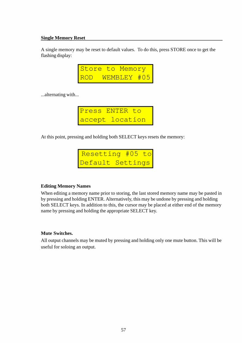
Store to MemoryROD WEMBLEY #05
Single Memory Reset
A single memory may be reset to default values. To do this, press STORE once to get theflashing display:
...alternating with...
Press ENTER to accept location
At this point, pressing and holding both SELECT keys resets the memory:
Resetting #05 to Default Settings
Editing Memory Names
When editing a memory name prior to storing, the last stored memory name may be pasted inby pressing and holding ENTER. Alternatively, this may be undone by pressing and holdingboth SELECT keys. In addition to this, the cursor may be placed at either end of the memoryname by pressing and holding the appropriate SELECT key.
Mute Switches.
All output channels may be muted by pressing and holding only one mute button. This will beuseful for soloing an output.

58
~ W R O 0 0 0 1 .d o c
~ W R O 0 0 0 0 .d o c
Analogue to Digital Converter Card & Input Level Control.
When the unit starts up, its checks to see if an ADC card is present (as opposed to a fullydigital I/O card), and what type of card it is. If no card is present, then a warning is displayed:
Input Card Not Present/Faulty!
If the card is of unrecognised type, the actual type number is displayed:
Unrecognised ADC Card Type:
If the card uses a standard or enhanced 20 bit ADC, then when the input level control isturned, increases in gain steps are reported to the screen due to the inclusion of a digitallycontrolled attenuator:
Input A:-11.7dB Input B:-10.9dB
As the two halves of the input pot are not friction-locked they operate independently.However, they may be “locked” via software by setting them to the same position and turningthem together several times. The unit will recognise this and change the display to show...
Inputs Ganged! A and B:-10.9dB
From this point on, it is only necessary to turn the front half of the pot (Channel A) to set thegain for both channels. They may be immediately un-ganged by turning the back half of thepot separately. This software “friction - lock” is remembered on power down.

59
Battery Low Warning.
If the memory backup battery starts to run low, then this is reported to the screen duringstart-up. In addition to this, the number of times that this warning has been given is alsodisplayed:
Back-up Battery Voltage Low !
alternating with:
Service Required Warning No.:NN
It is recommended that the DN8000 be referred to qualified personnel only.
If the battery is not changed, and the RAM becomes corrupted, it will be re-initialised withdefault values. This will be made apparent by a message of the form...
Resetting #NN to Default Settings
...and the mute LEDs flashing. The RAM is checked on a memory by memory basis so as topreserve as many user memories as possible - only those that are corrupted will be reset.

60
Three Dimensional Metering1
Accurate level metering is especially important on a crossover, being the last signalprocessing in the audio chain, with no further protection for individual drivers before thepower amplifiers if clipping occurs. Traditional bar graph level metering is only useful forclipping detection when the meters are being monitored all the time by the engineer.Occurrence of clipping conditions may be missed if the over range signal was transient andthe meter was not being directly viewed at the time.
Research in how to alleviate this situation has resulted in a dramatic improvement inperformance and presentation of information with regards to the metering incorporated intothe DN8000. By modulating the intensity of the meters as well as the traditional method ofilluminating more indicators to represent increased signal level, over range conditions can beregistered well off the central viewing axis.
In practise, any output which clips (or limits if the metering option is changed) will cause alarge step in the intensity of the entire output meter group. Whether this is an increase ordecrease in intensity depends on the setting of the LED brightness under the options menu.Similarly, clipping an input will cause both input meters to change intensity. The actual meter(or meters) that caused the over range condition will have their peak (red) LED’s held forabout 1.5 seconds. However this intensity change only lasts for the duration of the over rangecondition, giving yet more feedback as to the severity of the over-range condition -occasional flickering of the meter group indicates clipping point has been reached; frequentflickering indicates clipping point is being exceeded regularly; permanent high or low intensityor the meter group indicates severe clipping, and most likely would be clearly audible.
Note that, in the normal (bar graph) mode when the meters are monitoring dB from clip, ifclipping occurs somewhere in the signal path, but not at the output (for example, a parametricfilter has too much boost) the clip LED for that channel will light independently of the rest ofthe meter and cause the usual intensity change. This monitoring carries on even if the channelis muted, so if a red LED lights on a muted channel it means distortion is likely to be audibleif the channel is un-muted.
__________________________________1Patent has been applied for the three dimensional metering invention and is currently pending.
61
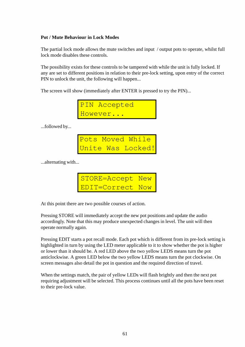
Pot / Mute Behaviour in Lock Modes
The partial lock mode allows the mute switches and input / output pots to operate, whilst fulllock mode disables these controls.
The possibility exists for these controls to be tampered with while the unit is fully locked. Ifany are set to different positions in relation to their pre-lock setting, upon entry of the correctPIN to unlock the unit, the following will happen...
The screen will show (immediately after ENTER is pressed to try the PIN)...
...followed by...
...alternating with...
At this point there are two possible courses of action.
Pressing STORE will immediately accept the new pot positions and update the audioaccordingly. Note that this may produce unexpected changes in level. The unit will thenoperate normally again.
Pressing EDIT starts a pot recall mode. Each pot which is different from its pre-lock setting ishighlighted in turn by using the LED meter applicable to it to show whether the pot is higheror lower than it should be. A red LED above the two yellow LEDS means turn the potanticlockwise. A green LED below the two yellow LEDS means turn the pot clockwise. Onscreen messages also detail the pot in question and the required direction of travel.
When the settings match, the pair of yellow LEDs will flash brightly and then the next potrequiring adjustment will be selected. This process continues until all the pots have been resetto their pre-lock value.
PIN AcceptedHowever...
Pots Moved WhileUnite Was Locked!
STORE=Accept NewEDIT=Correct Now

62
Completion of the process will restart the meters and the unit will operate as normal.
Switching the unit off during this process will cause it to power back up again.
Quick Lock.
This is a fast method for making the unit tamper proof without assigning a lockout PIN.When in the main screen if both SELECT keys are pressed together, quick lock is switchedon. To leave quick lock, press and hold both SELECT keys together again.
Generic Presets and Settings Tables.
A selection of templates are included in the unit to aid the setting up of the required system.These are the nine presets that immediately follow the user memories. They all have OEMparameter lists, and only the most important parameters are available for editing. If, however,access is required to modify this list, all nine of the generic presets may be unlocked byentering 00001 for the PIN. The details of the generic presets follow.
New Preset for Version 1.16
The two presets dedicated to control of X-Array systems have been removed from version1.15 and replaced with a set of six multi-purpose, fully reconfigurable versions. These appearas● EV XCB,XCN-ST;● EV XCB,XN-ST;● EV XDS;● EV XF,XB-ST;● EV XF,XN,XB,XC and● EV XN-ST
Full details about these presets are availble upon request.

63
2&2-WAY,MONO FR
Master Delay A:minimumMaster Delay B:minimum
OUT 1 OUT 2 OUT 3 OUT 4 OUT 5SOURCE A A B B A+BDELAY min min min min minPOLARITY normal normal normal normal normalPHASE ADJUST none none none none noneMUTE on on on on onLEVEL (dB) 0 0 0 0 0NAME Lo Hi Lo Hi SubHPF FREQUENCY 20 4000 20 4000 20HPF RESPONSE (dB/Oct) Butter 12 Butter 12 Full Range Butter 12 Butter 12HPF PEAK (dB) 0 0 0 0 0LPF FREQUENCY (Hz) 4000 20000 4000 20000 20000LPF RESPONSE (dB/Oct) Butter 12 Butter 12 Butter 12 Butter 12 Butter 12PEQ1 FREQUENCY (Hz) 20 20 20 20 20PEQ1 Q 1 1 1 1 1PEQ1 LEVEL (dB) 0 0 0 0 0PEQ2 FREQUENCY (Hz) 20 20 20 20 20PEQ2 Q 1 1 1 1 1PEQ2 LEVEL (dB) 0 0 0 0 0LEQ FREQUENCY (Hz) 20 20 20 20 20LEQ SLOPE (dB/Oct) 6 6 6 6 6LEQ LEVEL (dB) 0 0 0 0 0HEQ FREQUENCY (Hz) 500 500 500 500 500HEQ SLOPE (dB/Oct) 6 6 6 6 6HEQ LEVEL (dB) 0 0 0 0 0COMPRESSOR THRESHOLD(dB) 22 22 22 22 22COMPRESSOR RATIO 1:1 1:1 1:1 1:1 1:1COMPRESSOR ATTACK (ms) 0 0 0 0 0COMPRESSOR RELEASE (ms) 10 10 10 10 10GATE THRESHOLD (dB) -80 -80 -80 -80 -80GATE RANGE (dB) 0 0 0 0 0GATE DECAY TIME (dB/ms) 0.01 0.01 0.01 0.01 0.01LIMITER THRESHOLD (dB) 22 22 22 22 22

64
2&2-WAY,MONO SUB
Master Delay A:minimumMaster Delay B:minimum
OUT 1 OUT 2 OUT 3 OUT 4 OUT 5SOURCE A A B B A+BDELAY min min min min minPOLARITY normal normal normal normal normalPHASE ADJUST none none none none noneMUTE on on on on onLEVEL (dB) 0 0 0 0 0NAME Lo Hi Lo Hi SubHPF FREQUENCY 121 4000 121 4000 20HPF RESPONSE (dB/Oct) Butter 12 Butter 12 Butter 12 Butter 12 Butter 12HPF PEAK (dB) 0 0 0 0 0LPF FREQUENCY (Hz) 4000 20000 4000 20000 121LPF RESPONSE (dB/Oct) Butter 12 Butter 12 Butter 12 Butter 12 Butter 12PEQ1 FREQUENCY (Hz) 20 20 20 20 20PEQ1 Q 1 1 1 1 1PEQ1 LEVEL (dB) 0 0 0 0 0PEQ2 FREQUENCY (Hz) 20 20 20 20 20PEQ2 Q 1 1 1 1 1PEQ2 LEVEL (dB) 0 0 0 0 0LEQ FREQUENCY (Hz) 20 20 20 20 20LEQ SLOPE (dB/Oct) 6 6 6 6 6LEQ LEVEL (dB) 0 0 0 0 0HEQ FREQUENCY (Hz) 500 500 500 500 20HEQ SLOPE (dB/Oct) 6 6 6 6 6HEQ LEVEL (dB) 0 0 0 0 0COMPRESSOR THRESHOLD(dB) 22 22 22 22 22COMPRESSOR RATIO 1:1 1:1 1:1 1:1 1:1COMPRESSOR ATTACK (ms) 0 0 0 0 0COMPRESSOR RELEASE (ms) 10 10 10 10 10GATE THRESHOLD (dB) -80 -80 -80 -80 -80GATE RANGE (dB) 0 0 0 0 0GATE DECAY TIME (dB/ms) 0.01 0.01 0.01 0.01 0.01LIMITER THRESHOLD (dB) 22 22 22 22 22

65
3-WAY & 2-WAY
Master Delay A:minimumMaster Delay B:minimum
OUT 1 OUT 2 OUT 3 OUT 4 OUT 5SOURCE A A A B BDELAY min min min min minPOLARITY normal normal normal normal normalPHASE ADJUST none none none none noneMUTE on on on on onLEVEL (dB) 0 0 0 0 0NAME Lo Mid Hi Lo HiHPF FREQUENCY (Hz) 20 250 4000 20 4000HPF RESPONSE (dB/Oct) Bessel 24 Bessel 24 Bessel 24 Butter 12 Butter 12HPF PEAK (dB) 0 0 0 0 0LPF FREQUENCY (Hz) 250 4000 20000 4000 20000LPF RESPONSE (dB/Oct) Butter 24 Butter 24 Butter 24 Butter 12 Butter 12PEQ1 FREQUENCY (Hz) 20 20 20 20 20PEQ1 Q 1 1 1 1 1PEQ1 LEVEL (dB) 0 0 0 0 0PEQ2 FREQUENCY (Hz) 20 20 20 20 20PEQ2 Q 1 1 1 1 1PEQ2 LEVEL (dB) 0 0 0 0 0LEQ FREQUENCY (Hz) 20 20 20 20 20LEQ SLOPE (dB/Oct) 6 6 6 6 6LEQ LEVEL (dB) 0 0 0 0 0HEQ FREQUENCY (Hz) 500 500 500 500 500HEQ SLOPE (dB/Oct) 6 6 6 6 6HEQ LEVEL (dB) 0 0 0 0 0COMPRESSOR THRESHOLD(dB) 22 22 22 22 22COMPRESSOR RATIO 1:1 1:1 1:1 1:1 1:1COMPRESSOR ATTACK (ms) 0 0 0 0 0COMPRESSOR RELEASE (ms) 10 10 10 10 10GATE THRESHOLD (dB) -80 -80 -80 -80 -80GATE RANGE (dB) 0 0 0 0 0GATE DECAY TIME (dB/ms) 0.01 0.01 0.01 0.01 0.01LIMITER THRESHOLD (dB) 22 22 22 22 22

66
4-WAY,MONO FR
Master Delay A:minimumMaster Delay B:minimum
OUT 1 OUT 2 OUT 3 OUT 4 OUT 5SOURCE A A A A A+BDELAY min min min min minPOLARITY normal normal normal normal normalPHASE ADJUST none none none none noneMUTE on on on on onLEVEL (dB) 0 0 0 0 0NAME Lo Lo-Mid Hi-Mid Hi FRHPF FREQUENCY (Hz) 20 250 1000 8000 20HPF RESPONSE (dB/Oct) Lnk-Ril 12 Lnk-Ril 12 Lnk-Ril 12 Lnk-Ril 12 OFFHPF PEAK (dB) 0 0 0 0 0LPF FREQUENCY (Hz) 250 1000 8000 20000 20000LPF RESPONSE (dB/Oct) Lnk-Ril 12 Lnk-Ril 12 Lnk-Ril 12 Lnk-Ril 12 OFFPEQ1 FREQUENCY (Hz) 20 20 20 20 20PEQ1 Q 1 1 1 1 1PEQ1 LEVEL (dB) 0 0 0 0 0PEQ2 FREQUENCY (Hz) 20 20 20 20 20PEQ2 Q 1 1 1 1 1PEQ2 LEVEL (dB) 0 0 0 0 0LEQ FREQUENCY (Hz) 500 500 500 500 500LEQ SLOPE (dB/Oct) 6 6 6 6 6LEQ LEVEL (dB) 0 0 0 0 0HEQ FREQUENCY (Hz) 20 20 20 20 20HEQ SLOPE (dB/Oct) 6 6 6 6 6HEQ LEVEL (dB) 0 0 0 0 0COMPRESSOR THRESHOLD(dB) 22 22 22 22 22COMPRESSOR RATIO 1:1 1:1 1:1 1:1 1:1COMPRESSOR ATTACK (ms) 0 0 0 0 0COMPRESSOR RELEASE (ms) 10 10 10 10 10GATE THRESHOLD (dB) -80 -80 -80 -80 -80GATE RANGE (dB) 0 0 0 0 0GATE DECAY TIME (dB/ms) 0.01 0.01 0.01 0.01 0.01LIMITER THRESHOLD (dB) 22 22 22 22 22

67
4-WAY,MONO SUB
Master Delay A:minimumMaster Delay B:minimum
OUT 1 OUT 2 OUT 3 OUT 4 OUT 5SOURCE A A A A A+BDELAY min min min min minPOLARITY normal normal normal normal normalPHASE ADJUST none none none none noneMUTE on on on on onLEVEL (dB) 0 0 0 0 0NAME Lo Lo-Mid Hi-Mid Hi SubHPF FREQUENCY (Hz) 20 250 1000 8000 20HPF RESPONSE (dB/Oct) Lnk-Ril 12 Lnk-Ril 12 Lnk-Ril 12 Lnk-Ril 12 Butter 12HPF PEAK (dB) 0 0 0 0 0LPF FREQUENCY (Hz) 250 1000 8000 20000 121LPF RESPONSE (dB/Oct) Lnk-Ril 12 Lnk-Ril 12 Lnk-Ril 12 Lnk-Ril 12 6PEQ1 FREQUENCY (Hz) 20 20 20 20 20PEQ1 Q 1 1 1 1 1PEQ1 LEVEL (dB) 0 0 0 0 0PEQ2 FREQUENCY (Hz) 20 20 20 20 20PEQ2 Q 1 1 1 1 1PEQ2 LEVEL (dB) 0 0 0 0 0LEQ FREQUENCY (Hz) 20 20 20 20 20LEQ SLOPE (dB/Oct) 6 6 6 6 6LEQ LEVEL (dB) 0 0 0 0 0HEQ FREQUENCY (Hz) 500 500 500 500 500HEQ SLOPE (dB/Oct) 6 6 6 6 6HEQ LEVEL (dB) 0 0 0 0 0COMPRESSOR THRESHOLD(dB) 22 22 22 22 22COMPRESSOR RATIO 1:1 1:1 1:1 1:1 1:1COMPRESSOR ATTACK (ms) 0 0 0 0 0COMPRESSOR RELEASE (ms) 10 10 10 10 10GATE THRESHOLD (dB) -80 -80 -80 -80 -80GATE RANGE (dB) 0 0 0 0 0GATE DECAY TIME (dB/ms) 0.01 0.01 0.01 0.01 0.01LIMITER THRESHOLD (dB) 22 22 22 22 22

68
4-WAY,DI ON IN.A
Master Delay A:minimumMaster Delay B:minimum
OUT 1 OUT 2 OUT 3 OUT 4 OUT 5SOURCE A A A A ADELAY min min min min minPOLARITY normal normal normal normal normalPHASE ADJUST none none none none noneMUTE on on on on onLEVEL (dB) 0 0 0 0 0NAME Lo Lo-Mid Hi-Mid Hi FRHPF FREQUENCY (Hz) 20 250 1000 8000 20000HPF RESPONSE (dB/Oct) Lnk-Ril 12 Lnk-Ril 12 Lnk-Ril 12 Lnk-Ril 12 OFFHPF PEAK (dB) 0 0 0 0 0LPF FREQUENCY (Hz) 250 1000 8000 20000 20000LPF RESPONSE (dB/Oct) Lnk-Ril 12 Lnk-Ril 12 Lnk-Ril 12 Lnk-Ril 12 OFFPEQ1 FREQUENCY (Hz) 20 20 20 20 20PEQ1 Q 1 1 1 1 1PEQ1 LEVEL (dB) 0 0 0 0 0PEQ2 FREQUENCY (Hz) 20 20 20 20 20PEQ2 Q 1 1 1 1 1PEQ2 LEVEL (dB) 0 0 0 0 0LEQ FREQUENCY (Hz) 20 20 20 20 20LEQ SLOPE (dB/Oct) 6 6 6 6 6LEQ LEVEL (dB) 0 0 0 0 0HEQ FREQUENCY (Hz) 500 500 500 500 500HEQ SLOPE (dB/Oct) 6 6 6 6 6HEQ LEVEL (dB) 0 0 0 0 0COMPRESSOR THRESHOLD(dB) 22 22 22 22 22COMPRESSOR RATIO 1:1 1:1 1:1 1:1 1:1COMPRESSOR ATTACK (ms) 0 0 0 0 0COMPRESSOR RELEASE (ms) 10 10 10 10 10GATE THRESHOLD (dB) -80 -80 -80 -80 -80GATE RANGE (dB) 0 0 0 0 0GATE DECAY TIME (dB/ms) 0.01 0.01 0.01 0.01 0.01LIMITER THRESHOLD (dB) 22 22 22 22 22
69
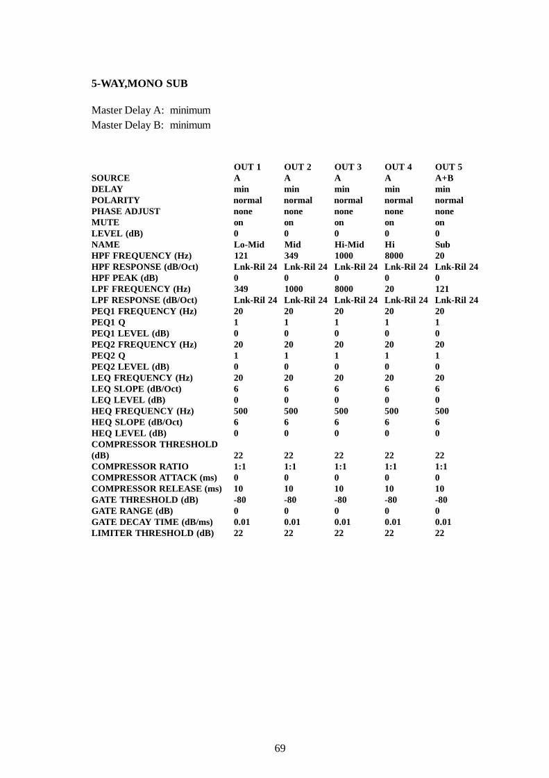
5-WAY,MONO SUB
Master Delay A:minimumMaster Delay B:minimum
OUT 1 OUT 2 OUT 3 OUT 4 OUT 5SOURCE A A A A A+BDELAY min min min min minPOLARITY normal normal normal normal normalPHASE ADJUST none none none none noneMUTE on on on on onLEVEL (dB) 0 0 0 0 0NAME Lo-Mid Mid Hi-Mid Hi SubHPF FREQUENCY (Hz) 121 349 1000 8000 20HPF RESPONSE (dB/Oct) Lnk-Ril 24 Lnk-Ril 24 Lnk-Ril 24 Lnk-Ril 24 Lnk-Ril 24HPF PEAK (dB) 0 0 0 0 0LPF FREQUENCY (Hz) 349 1000 8000 20 121LPF RESPONSE (dB/Oct) Lnk-Ril 24 Lnk-Ril 24 Lnk-Ril 24 Lnk-Ril 24 Lnk-Ril 24PEQ1 FREQUENCY (Hz) 20 20 20 20 20PEQ1 Q 1 1 1 1 1PEQ1 LEVEL (dB) 0 0 0 0 0PEQ2 FREQUENCY (Hz) 20 20 20 20 20PEQ2 Q 1 1 1 1 1PEQ2 LEVEL (dB) 0 0 0 0 0LEQ FREQUENCY (Hz) 20 20 20 20 20LEQ SLOPE (dB/Oct) 6 6 6 6 6LEQ LEVEL (dB) 0 0 0 0 0HEQ FREQUENCY (Hz) 500 500 500 500 500HEQ SLOPE (dB/Oct) 6 6 6 6 6HEQ LEVEL (dB) 0 0 0 0 0COMPRESSOR THRESHOLD(dB) 22 22 22 22 22COMPRESSOR RATIO 1:1 1:1 1:1 1:1 1:1COMPRESSOR ATTACK (ms) 0 0 0 0 0COMPRESSOR RELEASE (ms) 10 10 10 10 10GATE THRESHOLD (dB) -80 -80 -80 -80 -80GATE RANGE (dB) 0 0 0 0 0GATE DECAY TIME (dB/ms) 0.01 0.01 0.01 0.01 0.01LIMITER THRESHOLD (dB) 22 22 22 22 22
70
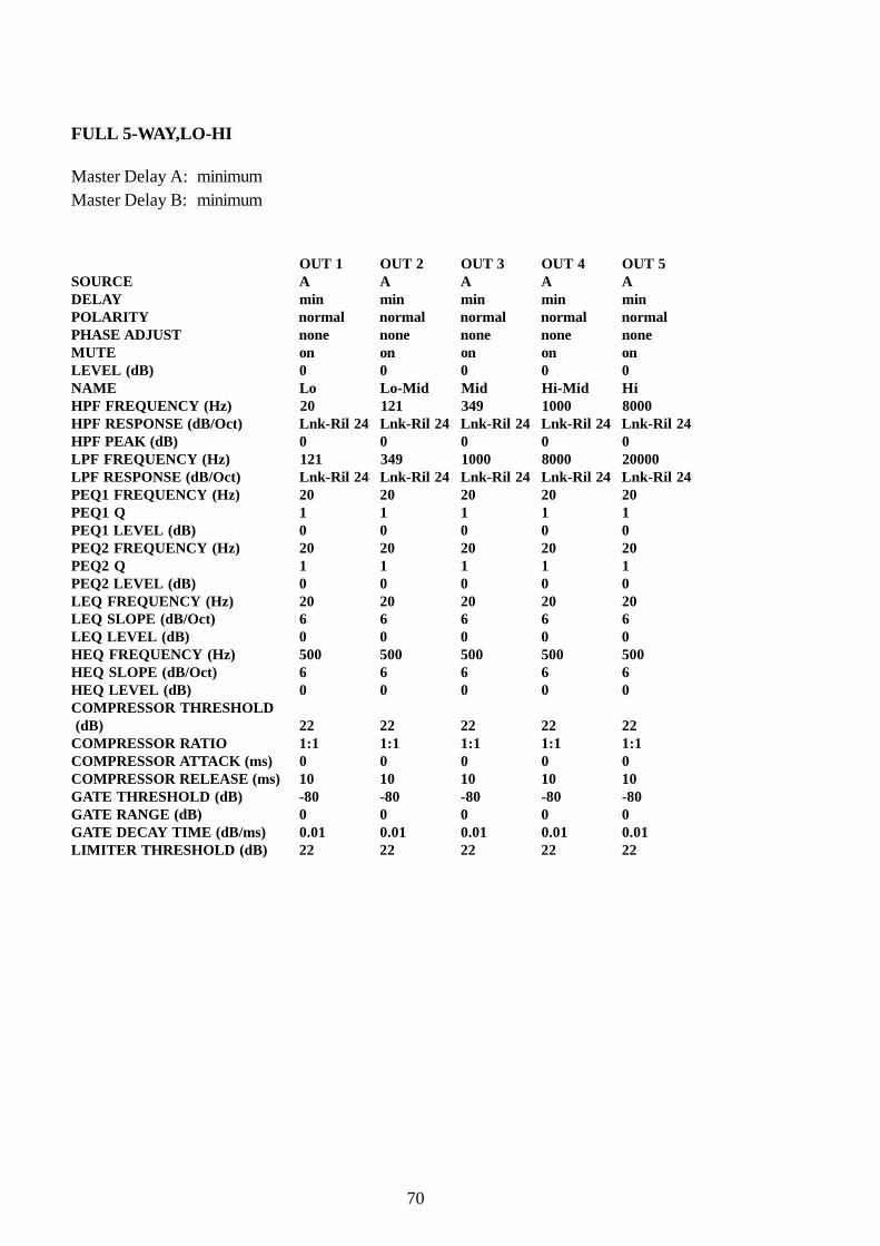
FULL 5-WAY,LO-HI
Master Delay A:minimumMaster Delay B:minimum
OUT 1 OUT 2 OUT 3 OUT 4 OUT 5SOURCE A A A A ADELAY min min min min minPOLARITY normal normal normal normal normalPHASE ADJUST none none none none noneMUTE on on on on onLEVEL (dB) 0 0 0 0 0NAME Lo Lo-Mid Mid Hi-Mid HiHPF FREQUENCY (Hz) 20 121 349 1000 8000HPF RESPONSE (dB/Oct) Lnk-Ril 24 Lnk-Ril 24 Lnk-Ril 24 Lnk-Ril 24 Lnk-Ril 24HPF PEAK (dB) 0 0 0 0 0LPF FREQUENCY (Hz) 121 349 1000 8000 20000LPF RESPONSE (dB/Oct) Lnk-Ril 24 Lnk-Ril 24 Lnk-Ril 24 Lnk-Ril 24 Lnk-Ril 24PEQ1 FREQUENCY (Hz) 20 20 20 20 20PEQ1 Q 1 1 1 1 1PEQ1 LEVEL (dB) 0 0 0 0 0PEQ2 FREQUENCY (Hz) 20 20 20 20 20PEQ2 Q 1 1 1 1 1PEQ2 LEVEL (dB) 0 0 0 0 0LEQ FREQUENCY (Hz) 20 20 20 20 20LEQ SLOPE (dB/Oct) 6 6 6 6 6LEQ LEVEL (dB) 0 0 0 0 0HEQ FREQUENCY (Hz) 500 500 500 500 500HEQ SLOPE (dB/Oct) 6 6 6 6 6HEQ LEVEL (dB) 0 0 0 0 0COMPRESSOR THRESHOLD (dB) 22 22 22 22 22COMPRESSOR RATIO 1:1 1:1 1:1 1:1 1:1COMPRESSOR ATTACK (ms) 0 0 0 0 0COMPRESSOR RELEASE (ms) 10 10 10 10 10GATE THRESHOLD (dB) -80 -80 -80 -80 -80GATE RANGE (dB) 0 0 0 0 0GATE DECAY TIME (dB/ms) 0.01 0.01 0.01 0.01 0.01LIMITER THRESHOLD (dB) 22 22 22 22 22

71
5-WAY DISTRIBUTE
Master Delay A:minimumMaster Delay B:minimum
OUT 1 OUT 2 OUT 3 OUT 4 OUT 5SOURCE A A A A ADELAY min min min min minPOLARITY normal normal normal normal normalPHASE ADJUST none none none none noneMUTE on on on on onLEVEL (dB) 0 0 0 0 0NAME FR FR FR FR FRHPF FREQUENCY (Hz) 20 20 20 20 20HPF RESPONSE (dB/Oct) OFF OFF OFF OFF OFFHPF PEAK (dB) 0 0 0 0 0LPF FREQUENCY (Hz) 20000 20000 20000 20000 20000LPF RESPONSE (dB/Oct) OFF OFF OFF OFF OFFPEQ1 FREQUENCY (Hz) 20 20 20 20 20PEQ1 Q 1 1 1 1 1PEQ1 LEVEL (dB) 0 0 0 0 0PEQ2 FREQUENCY (Hz) 20 20 20 20 20PEQ2 Q 1 1 1 1 1PEQ2 LEVEL (dB) 0 0 0 0 0LEQ FREQUENCY (Hz) 20 20 20 20 20LEQ SLOPE (dB/Oct) 6 6 6 6 6LEQ LEVEL (dB) 0 0 0 0 0HEQ FREQUENCY (Hz) 500 500 500 500 500HEQ SLOPE (dB/Oct) 6 6 6 6 6HEQ LEVEL (dB) 0 0 0 0 0COMPRESSOR THRESHOLD (dB) 22 22 22 22 22COMPRESSOR RATIO 1:1 1:1 1:1 1:1 1:1COMPRESSOR ATTACK (ms) 0 0 0 0 0COMPRESSOR RELEASE (ms) 10 10 10 10 10GATE THRESHOLD (dB) -80 -80 -80 -80 -80GATE RANGE (dB) 0 0 0 0 0GATE DECAY TIME (dB/ms) 0.01 0.01 0.01 0.01 0.01LIMITER THRESHOLD (dB) 22 22 22 22 22

72
TECHNICAL SPECIFICATION
INPUTS TWOType Balanced (electronically)Impedance (ohm)
Balanced 20KUnbalanced 10K
Common mode rejection >70dB@1KHzMaximum Level >+21dBu
OUTPUTS FIVEType Balanced (electronically)Min. load impedance 56 ohms//20nFSource impedance 56 ohmsMaximum level +22dB into > 2kohms
PERFORMANCEFrequency response +/-0.3dB(20Hz to 20KHz) With all filters and EQ flatDistortion @ +8dBu <0.02%(20Hz to 20KHz)Dynamic Range 114dB(20Hz to 20KHz unweighted)
POWER REQUIREMENTSVoltage 90 to 250V @ 50 to 60HzACConsumption <35VA
DIMENSIONSWidth 483mm (19 inches)Height 44mm (1.75 inches)Depth 287mm (12 inches)
WEIGHTNett 4 kgShipping 6 kg
OPTIONSInput isolation transformersOutput isolation transformersAES/EBU digital audio interfaceSecurity cover

73
ServiceInformation
74
SERVICE INFORMATION
Caution: These servicing instructions are for use by qualified personnel only. To reduce the riskof electric shock, do not perform any servicing other than that contained in the OperatingInstructions unless you are qualified to do so. Refer all servicing to qualified service personnel.Klark Teknik PLC accepts no liability for damage or injury arising from incorrect servicing.
Fuse ratings:Rear panel fuse holder: 500mAT
Battery Replacement
Caution!:Danger of explosion if battery is incorrectly replaced. Replace only with the same or equivalenttype recommended by the manufacturer. Discard used batteries according to the manufacturer'sinstructions.
Advarsel!:Lithiumbatteri. Eksplonsionsfare ved feijlagtig handtering. af samme fabrikat og type. Lever detbrugte batteri tilbage till leverandoren.
Voltage Change Over
The unit automatically adjusts to any input voltage in the range 100Vac to 240Vac @ 50Hz to60Hz.

75
OperatorsManual
DN8000
EVI PRO AUDIO GROUPKlark Teknik Building,
Walter Nash Road, Kidderminster,Worcestershire. DY11 7HJ.
England.
Tel:(01562) 741515 Fax:(01562) 745371