Embed Size (px)
Citation preview
4-1
Our Most Important Connection is with You.™
Introduction LC, SC and ST Series ........................................................................................................................................................4-2Markets and Applications .................................................................................................................................................4-2International Standard Documents Compliance .............................................................................................................4-2
LC SeriesFeatures and Benefits ......................................................................................................................................................4-3LC Standard ........................................................................................................................................................... 4-4 to 4-5LC for Harsh Environments .............................................................................................................................................4-6LC Adapters ..................................................................................................................................................................... 4-7
SC SeriesFeatures and Benefits ......................................................................................................................................................4-8SC Standard ........................................................................................................................................................ 4-9 to 4-10SC for Harsh Environments ...........................................................................................................................................4-11SC Adapters ...................................................................................................................................................................4-12
ST SeriesFeatures and Benefits ....................................................................................................................................................4-13ST Standard .....................................................................................................................................................................4-14ST Sealed Connection ....................................................................................................................................................4-15ST for Harsh Environments ...........................................................................................................................................4-16ST Receptacles ...............................................................................................................................................................4-17ST Adapters ....................................................................................................................................................................4-17
Accessories for LC, SC and ST SeriesDuplex Removable Clips ................................................................................................................................................4-18Inner Sleeves .................................................................................................................................................................4-18Crimping Rings ..............................................................................................................................................................4-19Connector Caps ..............................................................................................................................................................4-19Boots ................................................................................................................................................................. 4-20 to 4-21
Connector Kit ConfiguratorsLC Kit Configurator ........................................................................................................................................................4-22SC Kit Configurator ........................................................................................................................................................4-23ST Kit Configurator ........................................................................................................................................................4-23
Go online for data sheets & assembly instructions. Visit www.radiall.com and enter the part number.
SECT
ION
4 T
ABLE
OF
CON
TEN
TS
Contents
4-2
Our Most Important Connection is with You.™LC
/SC/
ST
Go online for data sheets & assembly instructions. Visit www.radiall.com and enter the part number.
Introduction
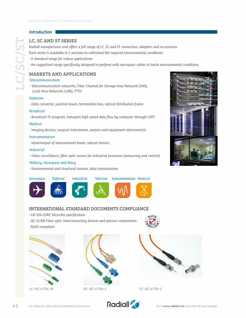
Radiall manufactures and offers a full range of LC, SC and ST connectors, adapters and accessories.
Each series is available in 2 versions to withstand the required environmental conditions:
- A standard range for indoor applications
- An ruggedized range specifically designed to perform with aerospace cables in harsh environmental conditions
MARKETS AND APPLICATIONSTelecommunication
- Telecommunication networks, Fiber Channel for Storage Area Network (SAN), Local Area Networks (LAN), FTTH
Datacom
- Data converter, junction boxes, termination box, optical distribution frame
Broadcast
- Broadcast TV program, transport high speed data flow by computer through CATV
Medical
- Imaging devices, surgical instruments, sensors and equipment interconnects
Instrumentation
- Input/output of measurement boxes, optical sensors
Industrial
- Video surveillance, fiber optic sensor for industrial processes (measuring and control)
Military, Aerospace and Navy
- Environmental and structural sensors, data transmissions
- GR-326-CORE Telcordia specification
- IEC 61300 Fiber optic interconnecting devices and passive components
- RoHS compliant
INTERNATIONAL STANDARD DOCUMENTS COMPLIANCE
LC, SC AND ST SERIES
Aerospace Defense Industrial Telecom Instrumentation Medical
LC: IEC 61754-20 SC: IEC 61754-4 ST: IEC 61754-2
4-3
Our Most Important Connection is with You.™
Go online for data sheets & assembly instructions. Visit www.radiall.com and enter the part number.
LC Series
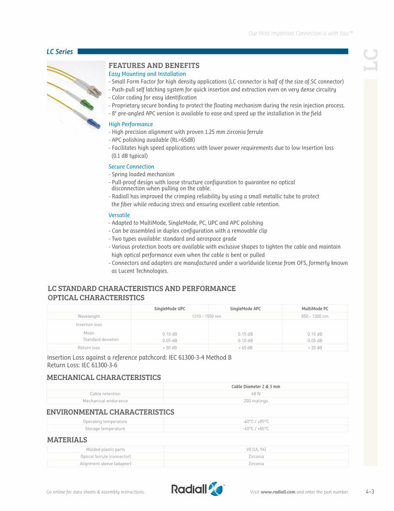
LC STANDARD CHARACTERISTICS AND PERFORMANCE
Easy Mounting and Installation- Small Form Factor for high density applications (LC connector is half of the size of SC connector)- Push-pull self latching system for quick insertion and extraction even on very dense circuitry- Color coding for easy identification- Proprietary secure bonding to protect the floating mechanism during the resin injection process.- 8° pre-angled APC version is available to ease and speed up the installation in the field
High Performance- High precision alignment with proven 1.25 mm zirconia ferrule- APC polishing available (RL>65dB)- Facilitates high speed applications with lower power requirements due to low Insertion loss (0.1 dB typical)
Secure Connection- Spring loaded mechanism- Pull-proof design with loose structure configuration to guarantee no optical disconnection when pulling on the cable.- Radiall has improved the crimping reliability by using a small metallic tube to protect the fiber while reducing stress and ensuring excellent cable retention.
Versatile- Adapted to MultiMode, SingleMode, PC, UPC and APC polishing- Can be assembled in duplex configuration with a removable clip- Two types available: standard and aerospace grade- Various protection boots are available with exclusive shapes to tighten the cable and maintain high optical performance even when the cable is bent or pulled- Connectors and adapters are manufactured under a worldwide license from OFS, formerly known as Lucent Technologies.
FEATURES AND BENEFITS
Cable Diameter 2 & 3 mm
Cable retention 68 NMechanical endurance 200 matings
Molded plastic parts V0 (UL 94)Optical ferrule (connector) ZirconiaAlignment sleeve (adapter) Zirconia
MATERIALS
Operating temperature -40°C / +85°CStorage temperature -40°C / +85°C
ENVIRONMENTAL CHARACTERISTICS
Insertion Loss against a reference patchcord: IEC 61300-3-4 Method BReturn Loss: IEC 61300-3-6
MECHANICAL CHARACTERISTICS
SingleMode UPC SingleMode APC MultiMode PC
Wavelength 1310 - 1550 nm 850 - 1300 nm
Insertion loss
Mean Standard deviation
0.10 dB0.05 dB
0.15 dB0.10 dB
0.10 dB0.05 dB
Return loss > 50 dB > 65 dB > 20 dB
OPTICAL CHARACTERISTICS
LC
4-4
Our Most Important Connection is with You.™
Go online for data sheets & assembly instructions. Visit www.radiall.com and enter the part number.
LC Series
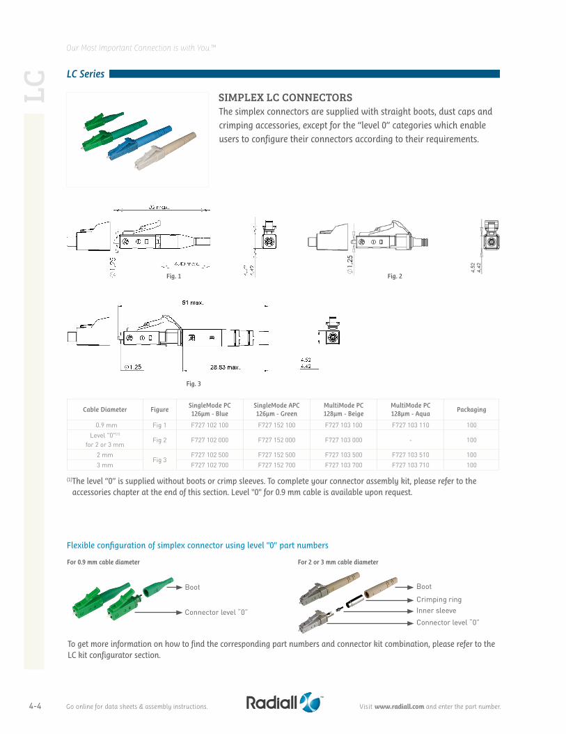
The simplex connectors are supplied with straight boots, dust caps and
crimping accessories, except for the “level 0” categories which enable
users to configure their connectors according to their requirements.
Fig. 1
Fig. 3
Fig. 2
Cable Diameter FigureSingleMode PC 126µm - Blue
SingleMode APC126µm - Green
MultiMode PC 128µm - Beige
MultiMode PC 128µm - Aqua
Packaging
0.9 mm Fig 1 F727 102 100 F727 152 100 F727 103 100 F727 103 110 100Level "0"(1)
for 2 or 3 mmFig 2 F727 102 000 F727 152 000 F727 103 000 - 100
2 mmFig 3
F727 102 500 F727 152 500 F727 103 500 F727 103 510 1003 mm F727 102 700 F727 152 700 F727 103 700 F727 103 710 100
(1) The level “0” is supplied without boots or crimp sleeves. To complete your connector assembly kit, please refer to the accessories chapter at the end of this section. Level "0" for 0.9 mm cable is available upon request.
For 0.9 mm cable diameter
Boot Boot
Crimping ringInner sleeveConnector level “0”Connector level “0”
For 2 or 3 mm cable diameter
Flexible configuration of simplex connector using level "0" part numbers
To get more information on how to find the corresponding part numbers and connector kit combination, please refer to the LC kit configurator section.
SIMPLEX LC CONNECTORSLC
4-5
Our Most Important Connection is with You.™
Go online for data sheets & assembly instructions. Visit www.radiall.com and enter the part number.
LC Series
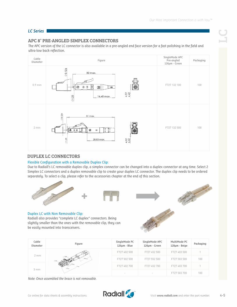
Cable Diameter Figure
SingleMode APC Pre-angled
126µm - GreenPackaging
0.9 mm F727 132 100 100
2 mm F727 132 500 100
APC 8° PRE-ANGLED SIMPLEX CONNECTORSThe APC version of the LC connector is also available in a pre-angled end face version for a fast polishing in the field and ultra-low back reflection.
DUPLEX LC CONNECTORSFlexible Configuration with a Removable Duplex Clip:Due to Radiall’s LC removable duplex clip, a simplex connector can be changed into a duplex connector at any time. Select 2 Simplex LC connectors and a duplex removable clip to create your duplex LC connector. The duplex clip needs to be ordered separately. To select a clip, please refer to the accessories chapter at the end of this section.
Note: Once assembled the brace is not removable.
Cable Diameter
FigureSingleMode PC 126µm - Blue
SingleMode APC 126µm - Green
MultiMode PC 128µm - Beige
Packaging
2 mm
(f727.402.500.jpg)
F727 402 500 F727 452 500 F727 403 500 1
F727 502 500 F727 552 500 F727 503 500 100
3 mmF727 402 700 F727 452 700 F727 403 700 1
- - F727 503 700 100
Duplex LC with Non Removable Clip:Radiall also provides “complete LC duplex” connectors. Being slightly smaller than the ones with the removable clip, they can be easily mounted into transceivers.
LC
4-6
Our Most Important Connection is with You.™LC
Go online for data sheets & assembly instructions. Visit www.radiall.com and enter the part number.
LC Series
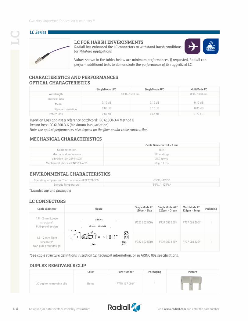
LC FOR HARSH ENVIRONMENTSRadiall has enhanced the LC connectors to withstand harsh conditions for Mil/Aero applications.
*Excludes cap and packaging
Operating temperature Thermal shocks (EN 2591-305) -55°C /+125°CStorage Temperature -55°C / +125°C*
ENVIRONMENTAL CHARACTERISTICS
SingleMode UPC SingleMode APC MultiMode PC
Wavelength 1300 - 1550 nm 850 - 1300 nm
Insertion loss
Mean
Standard deviation
0.10 dB 0.15 dB 0.10 dB
0.05 dB 0.10 dB 0.05 dB
Return loss > 50 dB > 65 dB > 20 dB
OPTICAL CHARACTERISTICS
Insertion Loss against a reference patchcord: IEC 61300-3-4 Method B Return loss: IEC 61300-3-6 (Maximum loss variation) Note: the optical performances also depend on the fiber and/or cable construction.
Cable Diameter: 1.8 – 2 mm
Cable retention 68 NMechanical endurance 500 matingsVibration (EN 2591-403) 27.7 grms
Mechanical shocks (EN2591-402) 50 g, 11 ms
MECHANICAL CHARACTERISTICS
DUPLEX REMOVABLE CLIPColor Part Number Packaging Picture
LC duplex removable clip Beige F718 197 006Y 1
Cable diameter Figure SingleMode PC126µm - Blue
SingleMode APC126µm - Green
MultiMode PC128µm - Beige Packaging
1.8 - 2 mm Loose structure*
Pull-proof designF727 002 500Y F727 052 500Y F727 003 500Y 1
1.8 - 2 mm Tight structure*
Non pull-proof designF727 002 520Y F727 052 520Y F727 003 520Y 1
*See cable structure definitions in section 12, technical information, or in ARINC 802 specifications.
LC CONNECTORS
CHARACTERISTICS AND PERFORMANCES
Values shown in the tables below are minimum performances. If requested, Radiall can perform additional tests to demonstrate the performance of its ruggedized LC.
4-7
Our Most Important Connection is with You.™
Go online for data sheets & assembly instructions. Visit www.radiall.com and enter the part number.
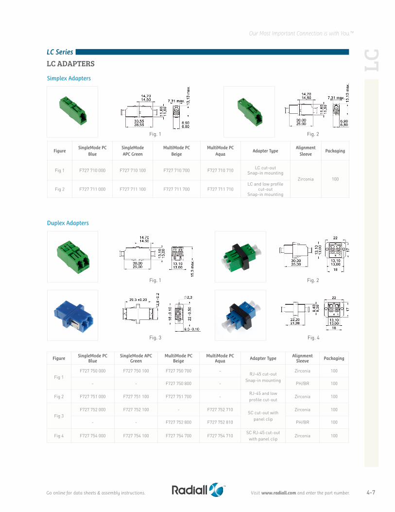
LC ADAPTERS
Fig. 1
Fig. 1
Fig. 3
Fig. 2
Fig. 2
Fig. 4
Figure SingleMode PC Blue
SingleMode APC Green
MultiMode PC Beige
MultiMode PC Aqua Adapter Type Alignment
Sleeve Packaging
Fig 1F727 750 000 F727 750 100 F727 750 700 -
RJ-45 cut-out Snap-in mounting
Zirconia 100
- - F727 750 800 - PH/BR 100
Fig 2 F727 751 000 F727 751 100 F727 751 700 -RJ-45 and low profile cut-out
Zirconia 100
Fig 3F727 752 000 F727 752 100 - F727 752 710
SC cut-out with panel clip
Zirconia 100
- - F727 752 800 F727 752 810 PH/BR 100
Fig 4 F727 754 000 F727 754 100 F727 754 700 F727 754 710SC RJ-45 cut-out
with panel clipZirconia 100
FigureSingleMode PC
BlueSingleMode APC Green
MultiMode PC Beige
MultiMode PC Aqua
Adapter TypeAlignment
SleevePackaging
Fig 1 F727 710 000 F727 710 100 F727 710 700 F727 710 710 LC cut-out Snap-in mounting
Zirconia 100
Fig 2 F727 711 000 F727 711 100 F727 711 700 F727 711 710LC and low profile
cut-out Snap-in mounting
LC Series
LC
Simplex Adapters
Duplex Adapters
4-8
Our Most Important Connection is with You.™
SC Series
SC STANDARD CHARACTERISTICS & PERFORMANCESOPTICAL CHARACTERISTICS
Insertion Loss against a reference patchcord: IEC 61300-3-4 Method BReturn Loss: IEC 61300-3-6Note: The optical performances also depend on the fiber and/or cable construction.
SingleMode PC SingleMode APC MultiMode PC
Wavelength 1310-1550 nm 850-1300 nm
Insertion LossMean
Standard deviation< 0.20 dB0.14 dB
< 0.20 dB0.15 dB
< 0.20 dB0.08 dB
Return Loss > 50 dB > 65 dB 20 dB
MECHANICAL CHARACTERISTICSCable Diameter 2 & 3 mm
Cable retention 100NMechanical endurance 200 matings
Operating temperature -40°C / + 85°C
Storage temperature -40°C / +85°C
Molded plastic parts V0 (UL 94)
Optical ferrule (connector) Zirconia
Alignment sleeve (adapter) Zirconia
ENVIRONMENTAL CHARACTERISTICS
MATERIALS
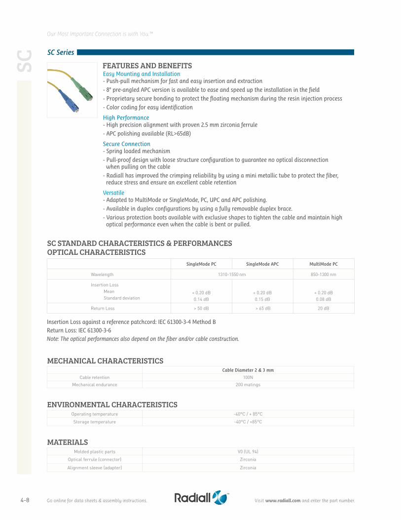
FEATURES AND BENEFITSEasy Mounting and Installation- Push-pull mechanism for fast and easy insertion and extraction
- 8° pre-angled APC version is available to ease and speed up the installation in the field
- Proprietary secure bonding to protect the floating mechanism during the resin injection process
- Color coding for easy identification
High Performance- High precision alignment with proven 2.5 mm zirconia ferrule
- APC polishing available (RL>65dB)
Secure Connection- Spring loaded mechanism
- Pull-proof design with loose structure configuration to guarantee no optical disconnection when pulling on the cable
- Radiall has improved the crimping reliability by using a mini metallic tube to protect the fiber, reduce stress and ensure an excellent cable retention
Versatile- Adapted to MultiMode or SingleMode, PC, UPC and APC polishing.
- Available in duplex configurations by using a fully removable duplex brace.
- Various protection boots available with exclusive shapes to tighten the cable and maintain high optical performance even when the cable is bent or pulled.
SC
Go online for data sheets & assembly instructions. Visit www.radiall.com and enter the part number.
4-9
Our Most Important Connection is with You.™
SC Series
Fig. 1
Fig. 2 Fig. 3
Cable Diameter FigureSingleMode PC 126µm - Blue
SingleMode APC 126µm - Green
MultiMode PC 126µm - Beige
MultiMode PC 128µm - Aqua
Packaging
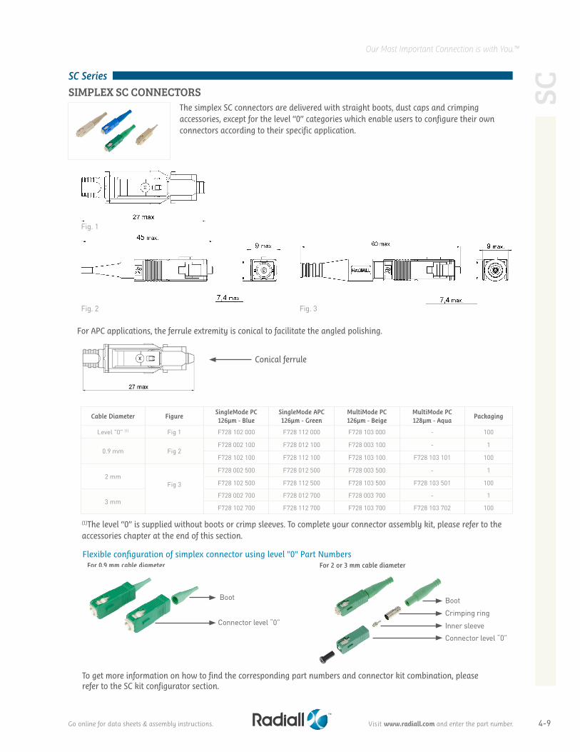
Level "0" (1) Fig 1 F728 102 000 F728 112 000 F728 103 000 - 100
0.9 mm Fig 2F728 002 100 F728 012 100 F728 003 100 - 1
F728 102 100 F728 112 100 F728 103 100 F728 103 101 100
2 mmFig 3
F728 002 500 F728 012 500 F728 003 500 - 1
F728 102 500 F728 112 500 F728 103 500 F728 103 501 100
3 mmF728 002 700 F728 012 700 F728 003 700 - 1
F728 102 700 F728 112 700 F728 103 700 F728 103 702 100
(1)The level “0” is supplied without boots or crimp sleeves. To complete your connector assembly kit, please refer to the accessories chapter at the end of this section.
SIMPLEX SC CONNECTORSThe simplex SC connectors are delivered with straight boots, dust caps and crimping accessories, except for the level “0” categories which enable users to configure their own connectors according to their specific application.
For APC applications, the ferrule extremity is conical to facilitate the angled polishing.
Conical ferrule
For 0.9 mm cable diameter
Boot
Connector level “0”
For 2 or 3 mm cable diameter
Boot
Crimping ring
Inner sleeve
Connector level “0”
To get more information on how to find the corresponding part numbers and connector kit combination, please refer to the SC kit configurator section.
Flexible configuration of simplex connector using level "0" Part Numbers
Go online for data sheets & assembly instructions. Visit www.radiall.com and enter the part number.
SC
4-10
Our Most Important Connection is with You.™
SC Series
SC
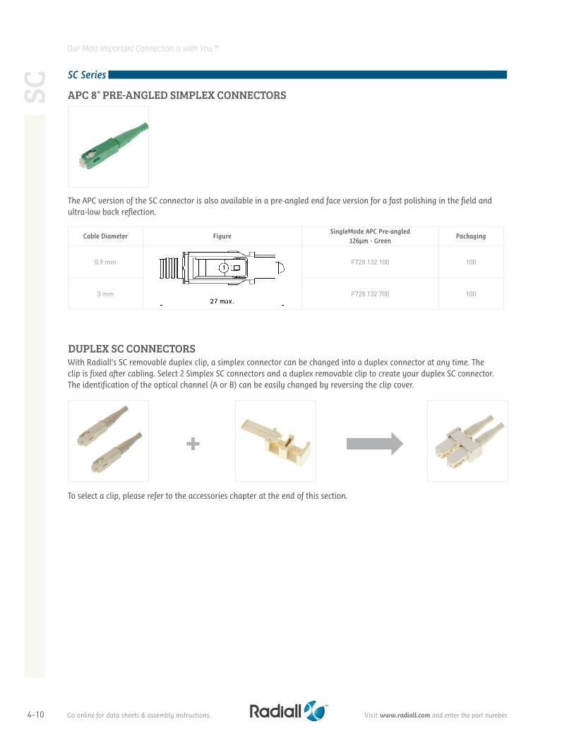
Cable Diameter FigureSingleMode APC Pre-angled
126µm - GreenPackaging
0.9 mm F728 132 100 100
3 mm F728 132 700 100
With Radiall’s SC removable duplex clip, a simplex connector can be changed into a duplex connector at any time. Theclip is fixed after cabling. Select 2 Simplex SC connectors and a duplex removable clip to create your duplex SC connector.The identification of the optical channel (A or B) can be easily changed by reversing the clip cover.
APC 8° PRE-ANGLED SIMPLEX CONNECTORS
The APC version of the SC connector is also available in a pre-angled end face version for a fast polishing in the field and ultra-low back reflection.
DUPLEX SC CONNECTORS
To select a clip, please refer to the accessories chapter at the end of this section.
Go online for data sheets & assembly instructions. Visit www.radiall.com and enter the part number.
4-11
Our Most Important Connection is with You.™
SC Series
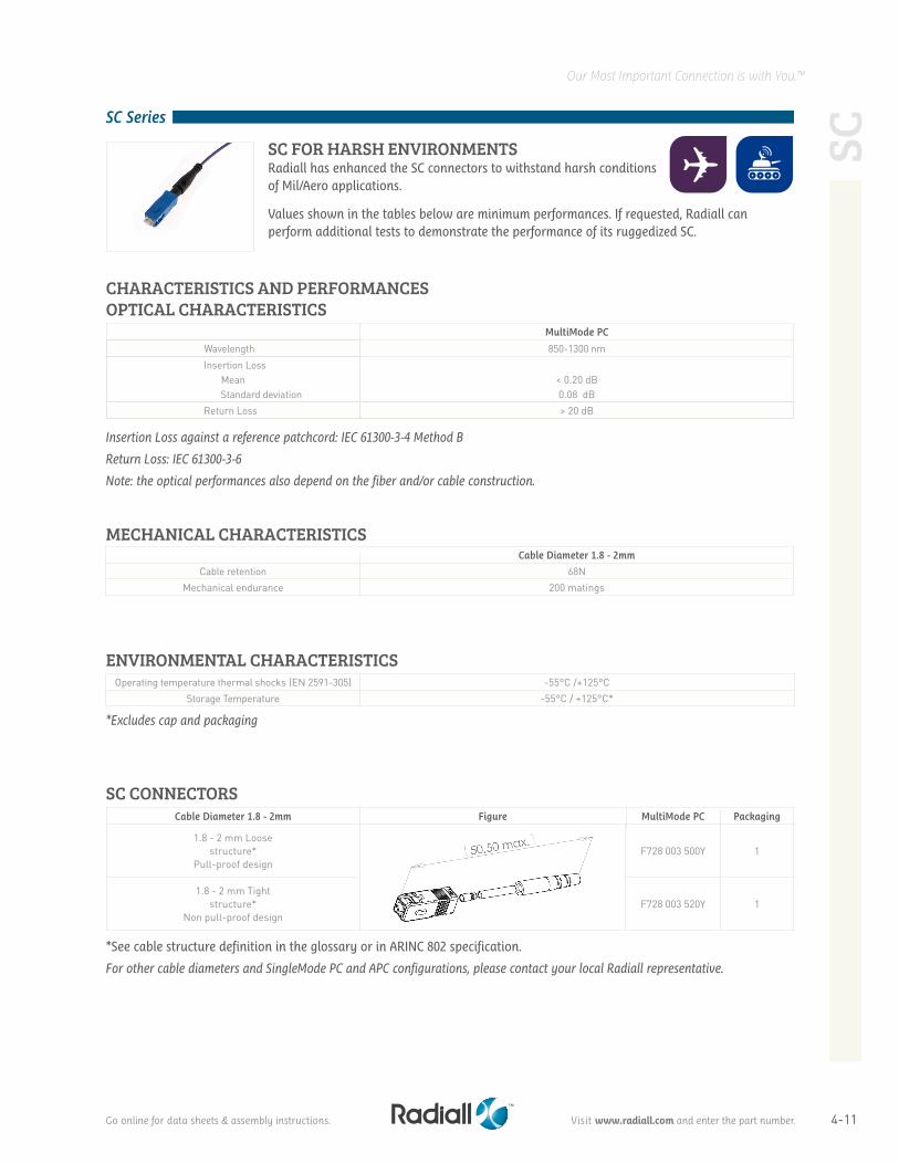
SC FOR HARSH ENVIRONMENTSRadiall has enhanced the SC connectors to withstand harsh conditions of Mil/Aero applications.
OPTICAL CHARACTERISTICS
Insertion Loss against a reference patchcord: IEC 61300-3-4 Method B
Return Loss: IEC 61300-3-6
Note: the optical performances also depend on the fiber and/or cable construction.
MultiMode PC
Wavelength 850-1300 nm Insertion Loss
Mean Standard deviation
< 0.20 dB0.08 dB
Return Loss > 20 dB
MECHANICAL CHARACTERISTICSCable Diameter 1.8 - 2mm
Cable retention 68NMechanical endurance 200 matings
*Excludes cap and packaging
Operating temperature thermal shocks (EN 2591-305) -55°C /+125°CStorage Temperature -55°C / +125°C*
ENVIRONMENTAL CHARACTERISTICS
SCSC CONNECTORS
Cable Diameter 1.8 - 2mm Figure MultiMode PC Packaging
1.8 - 2 mm Loosestructure*
Pull-proof designF728 003 500Y 1
1.8 - 2 mm Tightstructure*
Non pull-proof designF728 003 520Y 1
*See cable structure definition in the glossary or in ARINC 802 specification.
For other cable diameters and SingleMode PC and APC configurations, please contact your local Radiall representative.
CHARACTERISTICS AND PERFORMANCES
Values shown in the tables below are minimum performances. If requested, Radiall can perform additional tests to demonstrate the performance of its ruggedized SC.
Go online for data sheets & assembly instructions. Visit www.radiall.com and enter the part number.
4-12
Our Most Important Connection is with You.™
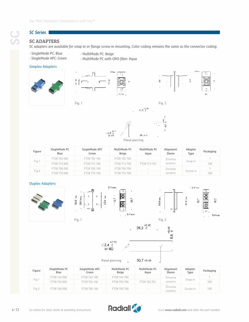
SC ADAPTERS SC adapters are available for snap-in or flange screw-in mounting. Color coding remains the same as the connector coding:
- SingleMode PC: Blue- SingleMode APC: Green
Fig. 1
Fig. 1
Fig. 2
Fig. 2
Panel piercing
Panel piercing
FigureSingleMode PC
BlueSingleMode APC
GreenMultiMode PC
BeigeMultiMode PC
AquaAlignment
SleeveAdapter
TypePackaging
Fig 1F728 703 000 F728 703 100 F728 703 700 - Zirconia
ceramicSnap in
1
F728 713 000 F728 713 100 F728 713 700 F728 713 701 100
Fig 2F728 700 000 F728 700 100 F728 700 700 - Zirconia
ceramicScrew in
1
F728 710 000 F728 710 100 F728 710 700 - 100
- MultiMode PC: Beige- MultiMode PC with OM3 fiber: Aqua
Figure SingleMode PCBlue
SingleMode APCGreen
MultiMode PC Beige
MultiMode PC Aqua
Alignment Sleeve
Adapter Type Packaging
Fig 1F728 743 000 F728 743 100 F728 743 700 - Zirconia
ceramicSnap in
1
F728 753 000 F728 753 100 F728 753 700 F728 753 701 100
Fig 2 F728 750 000 F728 750 100 F728 750 700 -Zirconia ceramic
Screw in 100
Simplex Adapters
Duplex Adapters
SCSC Series
Go online for data sheets & assembly instructions. Visit www.radiall.com and enter the part number.
4-13
Our Most Important Connection is with You.™
ST
ST Series
ST STANDARD CHARACTERISTICS AND PERFORMANCES
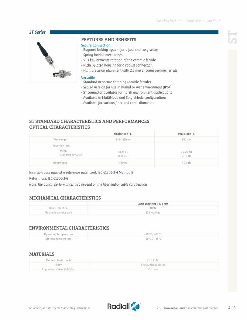
Secure Connection- Bayonet locking system for a fast and easy setup- Spring loaded mechanism- ST’s key prevents rotation of the ceramic ferrule- Nickel-plated housing for a robust connection- High precision alignment with 2.5 mm zirconia ceramic ferrule
Versatile- Standard or secure crimping (double ferrule)- Sealed version for use in humid or wet environment (IP64)- ST connector available for harsh environment applications- Available in MultiMode and SingleMode configurations- Available for various fiber and cable diameters
OPTICAL CHARACTERISTICS
FEATURES AND BENEFITS
Insertion Loss against a reference patchcord: IEC 61300-3-4 Method B
Return loss: IEC 61300-3-6
Note: The optical performances also depend on the fiber and/or cable construction.
MECHANICAL CHARACTERISTICSCable Diameter 2 & 3 mm
Cable retention 100NMechanical endurance 500 matings
ENVIRONMENTAL CHARACTERISTICS
MATERIALS
Operating temperature -40°C / +85°CStorage temperature -40°C / +85°C
Molded plastic parts V1 (UL 94)Body Brass, nickel plated
Alignment sleeve (adapter) Zirconia
SingleMode PC MultiMode PC
Wavelength 1310-1550 nm 850 nm
Insertion loss
Mean Standard deviation
< 0.25 dB0.11 dB
< 0.25 dB0.11 dB
Return loss > 50 dB > 20 dB
Go online for data sheets & assembly instructions. Visit www.radiall.com and enter the part number.
4-14
Our Most Important Connection is with You.™ST
ST Series
To get more information on how to find the corresponding part numbers and connector kit combination, please refer to the ST kit configurator at the end of this section.
For 2 or 3 mm cable diameter
Flexible Configuration Using Level “0” Part Numbers:
For 0.9 mm cable diameter
Boot for 0.9mm cable diameter
Boot for 2 or 3 mm cable diameter
Fig. 1
Fig. 3Fig. 2
Cable diameter Figure
Standard Crimping Secure Crimping
SingleMode PC 126µm
MultiMode PC 128µm
MultiMode PC 140µm
SingleMode PC 126µm
MultiMode PC 128µm
Packaging
Level "0" (1) Fig 1 F709 036 200 F709 025 200 - - - 100
0.9 mm
Fig 2
and
Fig 3
F709 034 706(2) F709 022 000 F709 090 000(2) - - 1
F709 034 200(2) F709 022 200 - - - 100
2 mm - - - - F709 097 200 100
3 mmF709 034 706(2) F709 024 000(2) F709 090 000(2) - - 1
F709 034 200(2) F709 024 200(2) - F709 096 200 F709 098 200 100
Standard crimping Secure crimping
Boot
Crimping ring
Connector level "0"
Boot
Connector level "0"
Cap
Cap
(1) The level “0” is supplied without boots or crimp sleeves. To complete your connector assembly kit, please refer to the accessories section.
(2)2 Boots are delivered with this PNFor other cable diameters, please contact your local Radiall representative.
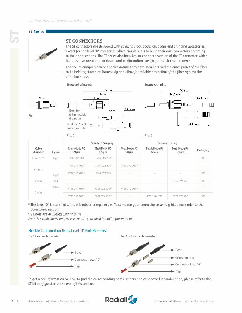
ST CONNECTORS
The ST connectors are delivered with straight black boots, dust caps and crimping accessories, except for the level “0” categories which enable users to build their own connectors according to their applications. The ST series also includes an enhanced version of the ST connector which features a secure crimping device and configuration specific for harsh environments.
The secure crimping device enables aramids strength members and the outer jacket of the fiber to be held together simultaneously and allow for reliable protection of the fiber against the crimping stress.
Go online for data sheets & assembly instructions. Visit www.radiall.com and enter the part number.
4-15
Our Most Important Connection is with You.™
1 2
3
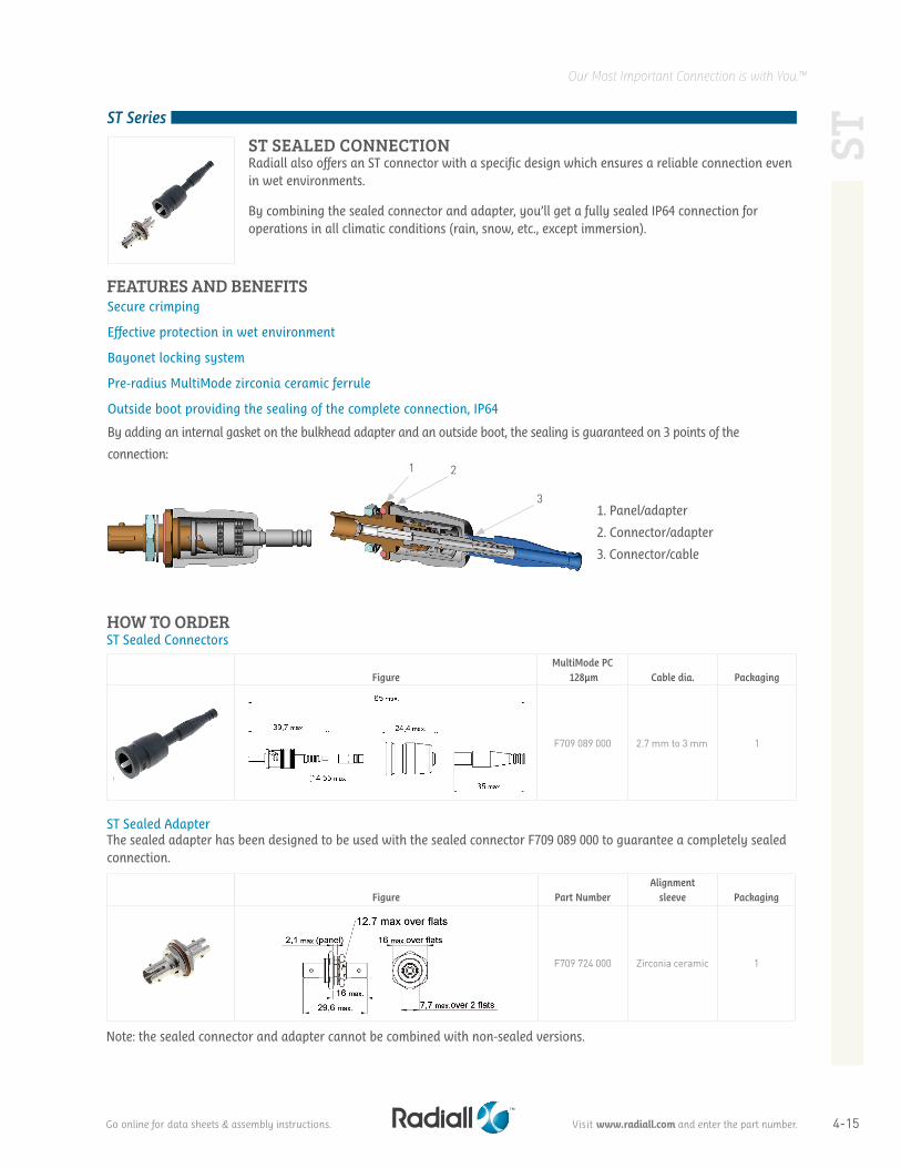
ST SEALED CONNECTION Radiall also offers an ST connector with a specific design which ensures a reliable connection even in wet environments.
By combining the sealed connector and adapter, you’ll get a fully sealed IP64 connection for operations in all climatic conditions (rain, snow, etc., except immersion).
FigureMultiMode PC
128µm Cable dia. Packaging
F709 089 000 2.7 mm to 3 mm 1
Figure Part NumberAlignment
sleeve Packaging
F709 724 000 Zirconia ceramic 1
HOW TO ORDER
ST Sealed Adapter
Secure crimping
Effective protection in wet environment
Bayonet locking system
Pre-radius MultiMode zirconia ceramic ferrule
Outside boot providing the sealing of the complete connection, IP64
By adding an internal gasket on the bulkhead adapter and an outside boot, the sealing is guaranteed on 3 points of the
connection:
FEATURES AND BENEFITS
The sealed adapter has been designed to be used with the sealed connector F709 089 000 to guarantee a completely sealed connection.
Note: the sealed connector and adapter cannot be combined with non-sealed versions.
1. Panel/adapter
2. Connector/adapter
3. Connector/cable
ST
ST Series
ST Sealed Connectors
Go online for data sheets & assembly instructions. Visit www.radiall.com and enter the part number.
4-16
Our Most Important Connection is with You.™ST
ST Series
Cable Diameter Figure MultiMode PC Packaging
1.8 - 2 mm Loose
structure*
Pull-proof design
F709 020 100Y 1
1.8 - 2 mm Tight
structure*
Non pull-proof design
F709 150 000Y 1
Insertion Loss against a reference patchcord: IEC 61300-3-4 method B
Return loss: IEC 61300-3-6 (Maximum loss variation)
Note: the optical performances also depend on the fiber and/or cable construction.
*See cable structure definition in the glossary or in ARINC 802 specification.
HOW TO ORDER
MECHANICAL CHARACTERISTICSCable Diameter: 1.8 max.
Cable retention 100NMechanical endurance 500 matings
MultiMode PC
Wavelength 850-1300 nmInsertion Loss
Mean Standard deviation
0.25 dB0.08 dB
Return Loss > 20 dB
CHARACTERISTICS AND PERFORMANCES
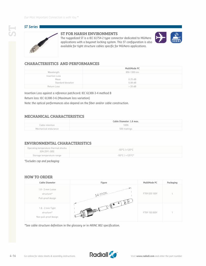
ST FOR HARSH ENVIRONMENTSThe ruggedized ST is a IEC 61754-2 type connector dedicated to Mil/Aero applications with a bayonet locking system. This ST configuration is also available for tight structure cables specific for Mil/Aero applications.
*Excludes cap and packaging
Operating temperature thermal shocks (EN 2591-305)
-55°C /+125°C
Storage temperature range -55°C / +125°C*
ENVIRONMENTAL CHARACTERISTICS
Go online for data sheets & assembly instructions. Visit www.radiall.com and enter the part number.
4-17
Our Most Important Connection is with You.™
ST
ST Series
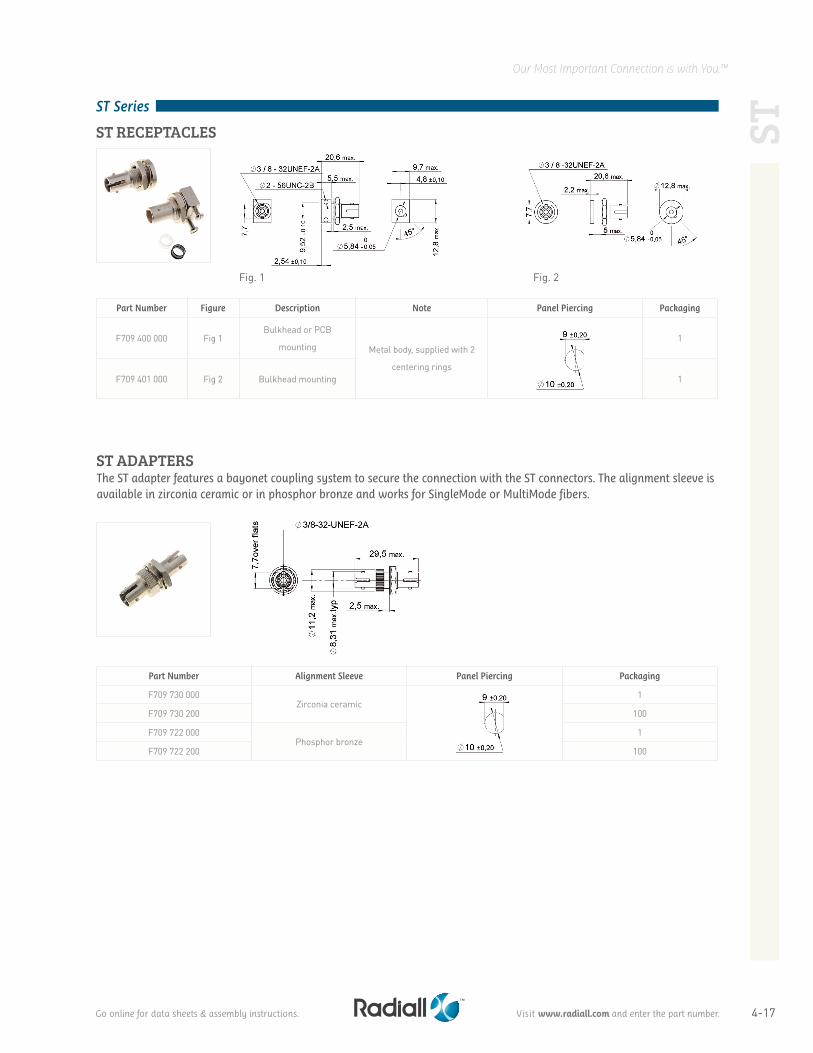
ST ADAPTERSThe ST adapter features a bayonet coupling system to secure the connection with the ST connectors. The alignment sleeve is available in zirconia ceramic or in phosphor bronze and works for SingleMode or MultiMode fibers.
Fig. 1 Fig. 2
Part Number Alignment Sleeve Panel Piercing Packaging
F709 730 000Zirconia ceramic
1
F709 730 200 100
F709 722 000Phosphor bronze
1
F709 722 200 100
Part Number Figure Description Note Panel Piercing Packaging
F709 400 000 Fig 1Bulkhead or PCB
mounting Metal body, supplied with 2
centering rings
1
F709 401 000 Fig 2 Bulkhead mounting 1
ST RECEPTACLES
Go online for data sheets & assembly instructions. Visit www.radiall.com and enter the part number.
4-18
Our Most Important Connection is with You.™
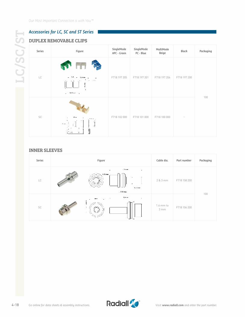
Accessories for LC, SC and ST Series
DUPLEX REMOVABLE CLIPS
INNER SLEEVES
Series FigureSingleMode APC - Green
SingleMode PC - Blue
MultiModeBeige
Black Packaging
LC F718 197 205 F718 197 201 F718 197 206 F718 197 200
100
SC F718 102 000 F718 101 000 F718 100 000 -
Series Figure Cable dia. Part number Packaging
LC 2 & 3 mm F718 158 200
100
SC1.6 mm to
3 mmF718 106 200
LC/S
C/ST
Go online for data sheets & assembly instructions. Visit www.radiall.com and enter the part number.
4-19
Our Most Important Connection is with You.™
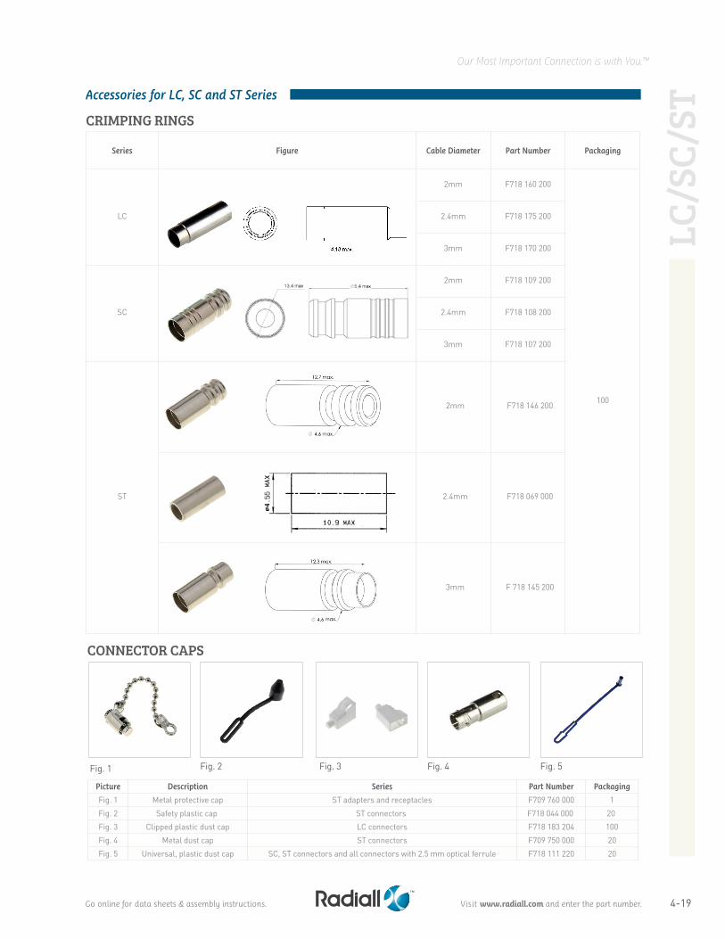
Accessories for LC, SC and ST Series
CRIMPING RINGS
Series Figure Cable Diameter Part Number Packaging
LC
2mm F718 160 200
100
2.4mm F718 175 200
3mm F718 170 200
SC
2mm F718 109 200
2.4mm F718 108 200
3mm F718 107 200
ST
2mm F718 146 200
2.4mm F718 069 000
3mm F 718 145 200
LC/S
C/ST
Fig. 1
Fig. 4Fig. 3Fig. 2Fig. 1 Fig. 5
CONNECTOR CAPS
Picture Description Series Part Number Packaging
Fig. 1 Metal protective cap ST adapters and receptacles F709 760 000 1
Fig. 2 Safety plastic cap ST connectors F718 044 000 20
Fig. 3 Clipped plastic dust cap LC connectors F718 183 204 100
Fig. 4 Metal dust cap ST connectors F709 750 000 20
Fig. 5 Universal, plastic dust cap SC, ST connectors and all connectors with 2.5 mm optical ferrule F718 111 220 20
Go online for data sheets & assembly instructions. Visit www.radiall.com and enter the part number.
4-20
Our Most Important Connection is with You.™
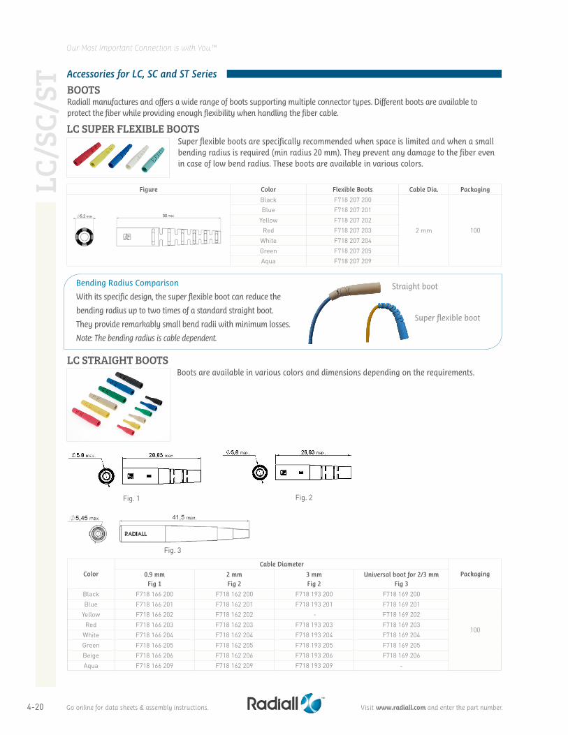
Figure Color Flexible Boots Cable Dia. Packaging
Black F718 207 200
2 mm 100
Blue F718 207 201Yellow F718 207 202
Red F718 207 203White F718 207 204Green F718 207 205Aqua F718 207 209
LC SUPER FLEXIBLE BOOTSSuper flexible boots are specifically recommended when space is limited and when a small bending radius is required (min radius 20 mm). They prevent any damage to the fiber even in case of low bend radius. These boots are available in various colors.
Fig. 1 Fig. 2
Fig. 3
Color
Cable Diameter
Packaging0.9 mmFig 1
2 mmFig 2
3 mmFig 2
Universal boot for 2/3 mmFig 3
Black F718 166 200 F718 162 200 F718 193 200 F718 169 200
100
Blue F718 166 201 F718 162 201 F718 193 201 F718 169 201Yellow F718 166 202 F718 162 202 - F718 169 202
Red F718 166 203 F718 162 203 F718 193 203 F718 169 203White F718 166 204 F718 162 204 F718 193 204 F718 169 204Green F718 166 205 F718 162 205 F718 193 205 F718 169 205Beige F718 166 206 F718 162 206 F718 193 206 F718 169 206Aqua F718 166 209 F718 162 209 F718 193 209 -
Boots are available in various colors and dimensions depending on the requirements.LC STRAIGHT BOOTS
Accessories for LC, SC and ST Series
BOOTSRadiall manufactures and offers a wide range of boots supporting multiple connector types. Different boots are available to protect the fiber while providing enough flexibility when handling the fiber cable.
Bending Radius Comparison
With its specific design, the super flexible boot can reduce the
bending radius up to two times of a standard straight boot.
They provide remarkably small bend radii with minimum losses.
Note: The bending radius is cable dependent.
Straight boot
Super flexible boot
LC/S
C/ST
Go online for data sheets & assembly instructions. Visit www.radiall.com and enter the part number.
4-21
Our Most Important Connection is with You.™
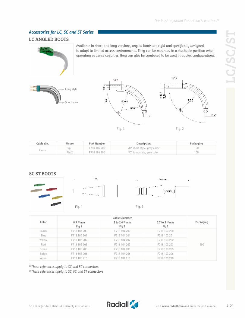
Cable dia. Figure Part Number Description Packaging
2 mmFig 1 F718 185 200 90° short style, grey color 100Fig 2 F718 186 200 90° long style, grey color 100
Long style
Short style
Fig. 1 Fig. 2
LC ANGLED BOOTSAvailable in short and long versions, angled boots are rigid and specifically designed to adapt to limited access environments. They can be mounted in a stackable position when operating in dense circuitry. They can also be combined to be used in duplex configurations.
(1)These references apply to SC and FC connectors (2)These references apply to SC, FC and ST connectors
Color
Cable Diameter
Packaging0.9 (1) mmFig 1
2 to 2.4 (2) mmFig 2
2.7 to 3 (2) mmFig 2
Black F718 105 200 F718 104 200 F718 103 200
100
Blue F718 105 201 F718 104 201 F718 103 201
Yellow F718 105 202 F718 104 202 F718 103 202
Red F718 105 203 F718 104 203 F718 103 203
Green F718 105 205 F718 104 205 F718 103 205
Beige F718 105 206 F718 104 206 F718 103 206
Aqua F718 105 210 F718 104 210 F718 103 210
SC ST BOOTS
Accessories for LC, SC and ST Series
LC/S
C/ST
Fig. 1 Fig. 2
Go online for data sheets & assembly instructions. Visit www.radiall.com and enter the part number.
4-22
Our Most Important Connection is with You.™
Notes: Refer to previous pages for angled or super flexible boot selection.
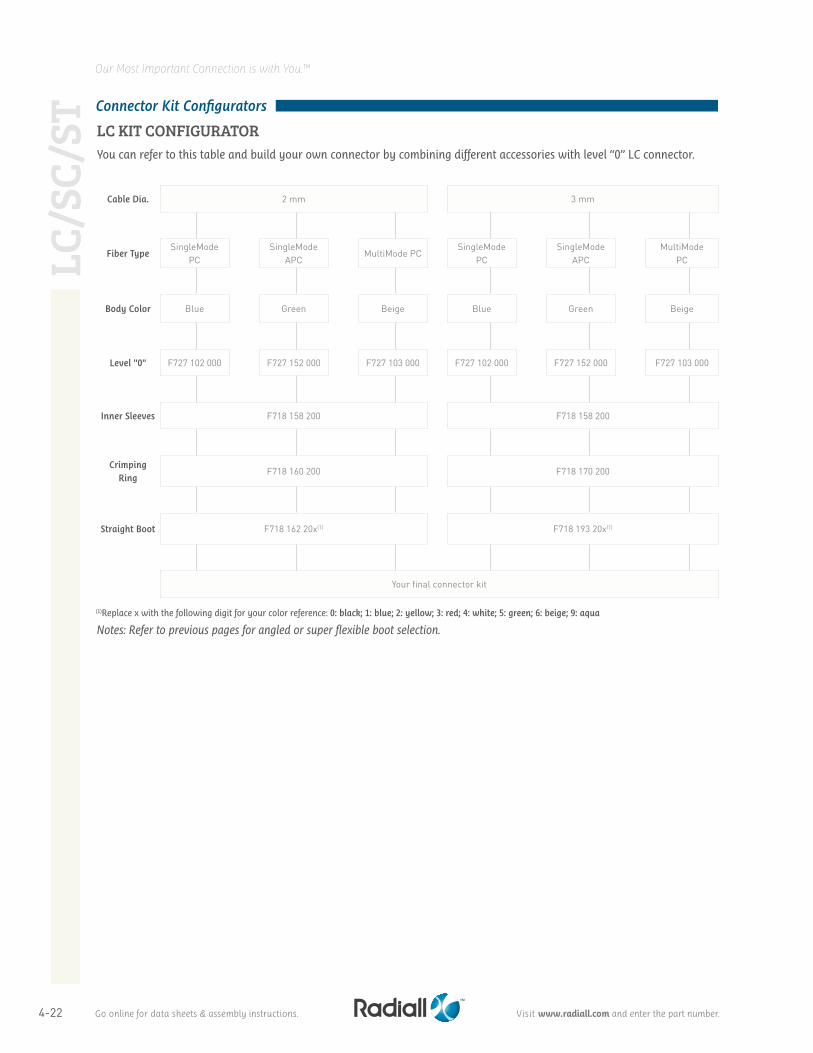
You can refer to this table and build your own connector by combining different accessories with level “0” LC connector.
Cable Dia. 2 mm 3 mm
Fiber TypeSingleMode
PCSingleMode
APCMultiMode PC
SingleMode PC
SingleMode APC
MultiMode PC
Body Color Blue Green Beige Blue Green Beige
Level "0" F727 102 000 F727 152 000 F727 103 000 F727 102 000 F727 152 000 F727 103 000
Inner Sleeves F718 158 200 F718 158 200
Crimping Ring
F718 160 200 F718 170 200
Straight Boot F718 162 20x(1) F718 193 20x(1)
Your final connector kit
Connector Kit Configurators
LC KIT CONFIGURATOR
(1)Replace x with the following digit for your color reference: 0: black; 1: blue; 2: yellow; 3: red; 4: white; 5: green; 6: beige; 9: aqua
LC/S
C/ST
LC
/SC/
ST
Go online for data sheets & assembly instructions. Visit www.radiall.com and enter the part number.
4-23
Our Most Important Connection is with You.™
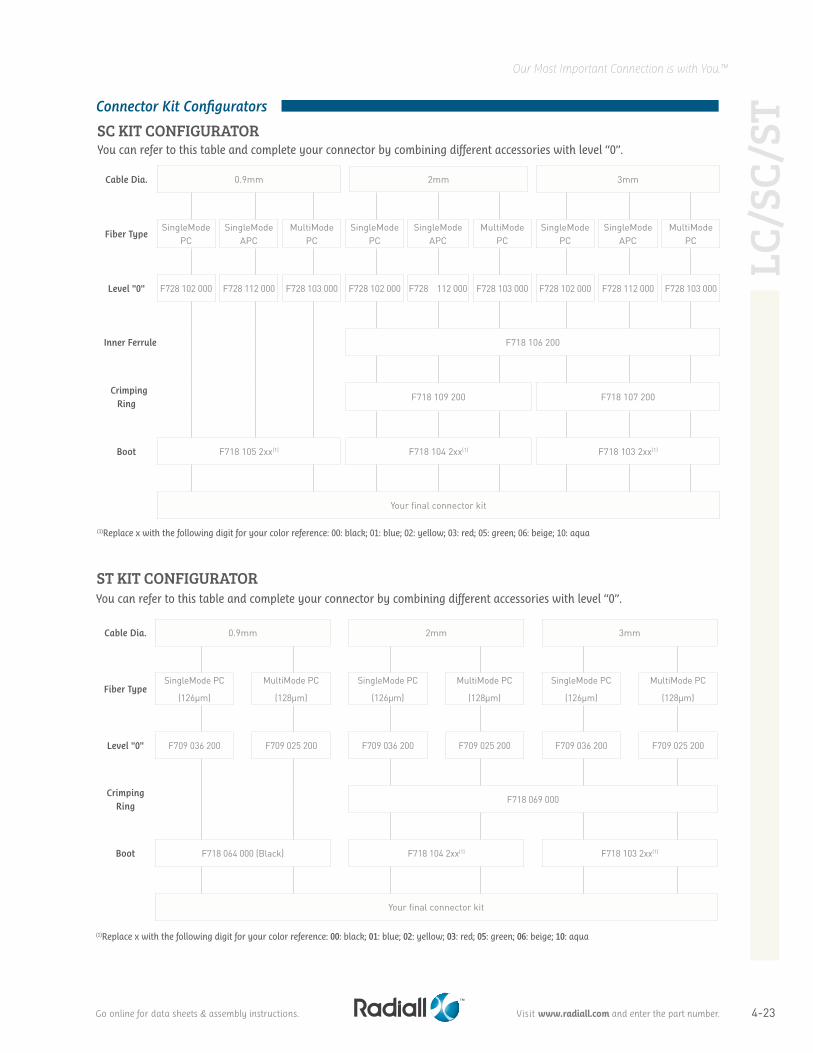
Cable Dia. 0.9mm 2mm 3mm
Fiber TypeSingleMode PC
(126µm)
MultiMode PC
(128µm)
SingleMode PC
(126µm)
MultiMode PC
(128µm)
SingleMode PC
(126µm)
MultiMode PC
(128µm)
Level "0" F709 036 200 F709 025 200 F709 036 200 F709 025 200 F709 036 200 F709 025 200
Crimping Ring
F718 069 000
Boot F718 064 000 (Black) F718 104 2xx(1) F718 103 2xx(1)
Your final connector kit
You can refer to this table and complete your connector by combining different accessories with level “0”.
Cable Dia. 0.9mm 2mm 3mm
Fiber TypeSingleMode
PCSingleMode
APCMultiMode
PCSingleMode
PCSingleMode
APCMultiMode
PCSingleMode
PCSingleMode
APCMultiMode
PC
Level "0" F728 102 000 F728 112 000 F728 103 000 F728 102 000 F728 112 000 F728 103 000 F728 102 000 F728 112 000 F728 103 000
Inner Ferrule F718 106 200
Crimping Ring
F718 109 200 F718 107 200
Boot F718 105 2xx(1) F718 104 2xx(1) F718 103 2xx(1)
Your final connector kit
You can refer to this table and complete your connector by combining different accessories with level “0”.
(1)Replace x with the following digit for your color reference: 00: black; 01: blue; 02: yellow; 03: red; 05: green; 06: beige; 10: aqua
(1)Replace x with the following digit for your color reference: 00: black; 01: blue; 02: yellow; 03: red; 05: green; 06: beige; 10: aqua
Connector Kit Configurators
SC KIT CONFIGURATOR
ST KIT CONFIGURATOR
LC/S
C/ST
Go online for data sheets & assembly instructions. Visit www.radiall.com and enter the part number.

4-24
Our Most Important Connection is with You.™
Notes
NOT
ES
Go online for data sheets & assembly instructions. Visit www.radiall.com and enter the part number.