Embed Size (px)
Citation preview
G.1
Contents
RockStar® accessories
Crimp contacts G.2
Tools G.10
Coding G.14
Adapter plates / Cover plates G.16
Other accessories G.17
RockStar® accessories
Ro
ckS
tar®
acc
esso
ries
G

G.2
G
Ro
ckS
tar®
acc
esso
ries
Crimp contacts
Crimping is an electrically and mechanically safe and reliableconnection between conductor and contact. An ideal crimpconnection is gas-proof and resistant to corrosion.
Weidmuller crimp contacts are supplied in solid, turned formand are optionally available with gold or silver surface.
Fiber optic contacts
Optical fibers guarantee interference-free transmission withoutany feedback – and this without additional overvoltage andexplosion protection.
Fiber optic contacts can be used without any EMC problems.Their geometry is the same as the HD contacts so they can beused in HD series inserts and the ConCept modular system.
Crimp contacts
Overview

G.3
G
Ro
ckS
tar®
acc
esso
ries
Crimping tool Order No.
CTX CM 1.6 / 2.5 9018490000
CTIN CM 1.6 / 2.5 9205430000
Crimping tools for 4.00 mm2
CZB 1 9012710000
Contact release tool
Removal Tool HE 1866750000
Crimp contacts
Technical datafor HD and HDD inserts for HE and HEE inserts
Material Copper alloy Copper alloy
Surface hard gold-plated 0.8 µm 0.8 µm
Surface hard silver-plated 3 µm 3 µm
Contact resistance ≤ 4 mΩ ≤ 4 mΩ
Clamping range 0.14 ... 2.5 mm2 0.5 ... 4.0 mm2
26 ... 14 AWG 20 ... 12 AWG
Stripping length 8 mm 7.5 mm
Fixed pole inserts
Qty Male Order No. Female Order No.
100 HDC-C-HD-SM0.14-0.37AG 1651520000 HDC-C-HD-BM0.14-0.37AG 1651570000
100 HDC-C-HD-SM0.5AG 1651530000 HDC-C-HD-BM0.5AG 1651580000
100 HDC-C-HD-SM0.75-1.00AG 1601750000 HDC-C-HD-BM0.75-1.00AG 1601760000
100 HDC-C-HD-SM1.5AG 1651550000 HDC-C-HD-BM1.5AG 1651600000
100 HDC-C-HD-SM2.5AG 1651560000 HDC-C-HD-BM2.5AG 1651610000
100 HDC-C-HD-SM0.14-0.37AU 1651620000 HDC-C-HD-BM0.14-0.37AU 1651670000
100 HDC-C-HD-SM0.5AU 1651630000 HDC-C-HD-BM0.5AU 1651680000
100 HDC-C-HD-SM0.75-1.00AU 1651640000 HDC-C-HD-BM0.75-1.00AU 1651690000
100 HDC-C-HD-SM1.5AU 1651650000 HDC-C-HD-BM1.5AU 1651700000
100 HDC-C-HD-SM2.5AU 1651660000 HDC-C-HD-BM2.5AU 1651710000
Crimp contacts
Crimping tool Order No.
CTX CM 1.6 / 2.5 9018490000
CTIN CM 1.6 / 2.5 9205430000
Contact release tool
Removal Tool HD 1866730000
For HD and HDD inserts
Tools
Qty Male Order No. Female Order No.
100 HDC-C-HE-SM0.5AG 1200500000 HDC-C-HE-BM0.5AG 1201100000
100 HDC-C-HE-SM0.75-1.00AG 1200600000 HDC-C-HE-BM0.75-1.00AG 1201200000
100 HDC-C-HE-SM1.5AG 1200700000 HDC-C-HE-BM1.5AG 1201300000
100 HDC-C-HE-SM2.5AG 1200800000 HDC-C-HE-BM2.5AG 1201400000
100 HDC-C-HE-SM4.0AG 1200900000 HDC-C-HE-BM4.0AG 1201500000
100 HDC-C-HE-SM0.5AU 1651420000 HDC-C-HE-BM0.5AU 1651470000
100 HDC-C-HE-SM0.75-1.00AU 1651430000 HDC-C-HE-BM0.75-1.00AU 1651480000
100 HDC-C-HE-SM1.5AU 1651440000 HDC-C-HE-BM1.5AU 1651490000
100 HDC-C-HE-SM2.5AU 1651450000 HDC-C-HE-BM2.5AU 1651500000
100 HDC-C-HE-SM4.0AU 1651460000 HDC-C-HE-BM4.0AU 1651510000
Crimp contacts
For HE and HEE inserts and CM-HE modules
Tools
Surface Silver
Surface Gold
Surface Silver
Surface Gold
Conductor cross-section Insulation stripping length
0.14 – 0.37 mm2 AWG 26-22 8 mm
0.50 mm2 AWG 20 8 mm
0.75 – 1.00 mm2 AWG 18 8 mm
1.50 mm2 AWG 16 8 mm
2.50 mm2 AWG 14 6 mm
25
3.5 steel spring1.6
3.5
21.6
steel spring
Conductor cross-section Insulation stripping length
0.50 mm2 AWG 20 7.5 mm
0.75 – 1.00 mm2 AWG 18 7.5 mm
1.50 mm2 AWG 16 7.5 mm
2.50 mm2 AWG 14 7.5 mm
4.00 mm2 AWG 12 7.5 mm
7.625
4.52.5
7.5
4.5
22.3

G.4
G
Ro
ckS
tar®
acc
esso
ries
Crimp contacts
Technical dataFor HQ and MixMate inserts
Material Copper alloy
Surface Passivated silver
Contact resistance ≤ 5 mΩ
Clamping range 1.5 ... 6 mm2
16 ... 10 AWG
Stripping length 8 mm
Fixed pole inserts
Accessories
Crimp contacts
Surface Silver
Qty Male Order No. Female Order No.
25 HDC C HX SM1.5AG 1002910000 HDC C HX BM1.5AG 1002950000
25 HDC C HX SM2.5AG 1002920000 HDC C HX BM2.5AG 1002960000
25 HDC C HX SM4.0AG 1002930000 HDC C HX BM4.0AG 1002970000
25 HDC C HX SM6.0AG 1002940000 HDC C HX BM6.0AG 1002980000
ToolsCrimping tool Order No.
CTIN CM 1.6/2.5 9205430000
Contact release tool
Removal Tool HX 1002990000
2 3
Conductor cross-section Insulation stripping length
1.50 mm2 AWG 16 8 mm
2.50 mm2 AWG 14 8 mm
4.00 mm2 AWG 12 8 mm
6.00 mm2 AWG 10 8 mm
29.1
Ø 6
23.6
Ø 4
Ø 6
Ø 6
G.5
G
Ro
ckS
tar®
acc
esso
ries

G.6
G
Ro
ckS
tar®
acc
esso
ries
Crimping tool Order No.
CTX CM 1.6 / 2.5 9018490000
Contact release tool
Removal Tool CM5 1866720000
Crimp contacts
Technical dataCM-3 CM-5 CM-10 CM-20 CM-HE
Material Copper alloy Copper alloy Copper alloy Copper alloy Copper alloy
Surface hard gold-plated 0.8 µm 0.1 ... 0.2 µm 0.8 µm
Surface hard silver-plated 3 µm 3 µm 3 µm 3 µm
Contact resistance ≤ 4 mΩ ≤ 4 mΩ ≤ 4 mΩ ≤ 4 mΩ ≤ 4 mΩ
Clamping range 1.5 ... 10 mm2 0.75 ... 4.0 mm2 0.14 ... 2.5 mm2 0.08 ... 0.52 mm2 0.5 ... 4.0 mm2
12 ... 7 AWG 20 ... 12 AWG 26 ... 14 AWG 28 ... 20 AWG 20 ... 12 AWG
Stripping length 10 mm 7 mm 8 mm (6mm) 2.5 + 0.5 mm 7.4 mm
For ConCept modular system
Qty Male Order No. Female Order No.
100 HDC-C-M3-SM1.5AG 1698120000 HDC-C-M3-BM1.5AG 1698130000
100 HDC-C-M3-SM2.5AG 1698140000 HDC-C-M3-BM2.5AG 1698150000
100 HDC-C-M3-SM4.0AG 1682260000 HDC-C-M3-BM4.0AG 1682270000
100 HDC-C-M3-SM6.0AG 1682280000 HDC-C-M3-BM6.0AG 1682290000
100 HDC-C-M3-SM10.0AG 1682300000 HDC-C-M3-BM10.0AG 1682310000
5
30 75
3 6 steel spring 12
6.1
10 2
5
28 2 5 steel spring
12
6.1
10 2
1.50 mm 2 AWG 16 10 mm
2.50 mm 2 AWG 14 10 mm
4.00 mm 2 AWG 12 10 mm
6.00 mm 2 AWG 10 10 mm
10.00 mm 2 AWG 7 10 mm
Conductor cross-section Insulation stripping length
Crimp contacts
Crimping tool 1.5 ... 2.5 mm2 Order No.
CTX CM 1.6 / 2.5 9018490000
Crimping tool 4 ... 10 mm2
CTX CM 3.6 9018480000
Crimping tool 1.5 ... 10 mm2
HDC-CM-3 1700890000
Contact release tool
Removal Tool CM3 1866710000
For CM-3 modules
Tools
Qty Male Order No. Female Order No.
100 HDC-C-M5-SM0.5AG 1682320000 HDC-C-M5-BM0.5AG 1682330000
100 HDC-C-M5-SM0.75-1.00AG 1682340000 HDC-C-M5-BM0.75-1.00AG 1682350000
100 HDC-C-M5-SM1.5AG 1682360000 HDC-C-M5-BM1.5AG 1682370000
100 HDC-C-M5-SM2.5AG 1682380000 HDC-C-M5-BM2.5AG 1682390000
100 HDC-C-M5-SM4.0AG 1682400000 HDC-C-M5-BM4.0AG 1682410000
2 5 steel spring
8
4.1
4 6
26 75 24 25 steel spring
4. 1
8
4
6
0.75 - 1.00 mm 2 AWG 18 7 mm
1.50 mm 2 AWG 16 7 mm
2.50 mm 2 AWG 14 7 mm
4.00 mm 2 AWG 12 7 mm
Conductor cross-section Insulation stripping length
Crimp contacts
For CM-5 modules
Tools
Surface Silver
Surface Silver

G.7
G
Ro
ckS
tar®
acc
esso
ries
Reel with 300 contactsNote
Crimp contacts
Qty Male Order No. Female Order No.
100 HDC-C-HD-SM0.14-0.37AG 1651520000 HDC-C-HD-BM0.14-0.37AG 1651570000
100 HDC-C-HD-SM0.5AG 1651530000 HDC-C-HD-BM0.5AG 1651580000
100 HDC-C-HD-SM0.75-1.00AG 1601750000 HDC-C-HD-BM0.75-1.00AG 1601760000
100 HDC-C-HD-SM1.5AG 1651550000 HDC-C-HD-BM1.5AG 1651600000
100 HDC-C-HD-SM2.5AG 1651560000 HDC-C-HD-BM2.5AG 1651610000
100 HDC-C-HD-SM0.14-0.37AU 1651620000 HDC-C-HD-BM0.14-0.37AU 1651670000
100 HDC-C-HD-SM0.5AU 1651630000 HDC-C-HD-BM0.5AU 1651680000
100 HDC-C-HD-SM0.75-1.00AU 1651640000 HDC-C-HD-BM0.75-1.00AU 1651690000
100 HDC-C-HD-SM1.5AU 1651650000 HDC-C-HD-BM1.5AU 1651700000
100 HDC-C-HD-SM2.5AU 1651660000 HDC-C-HD-BM2.5AU 1651710000
Conductor cross-section Insulation stripping length
0.14 – 0.37 mm2 AWG 26-22 8 mm
0.50 mm2 AWG 20 8 mm
0.75 – 1.00 mm2 AWG 18 8 mm
1.50 mm2 AWG 16 8 mm
2.50 mm2 AWG 14 6 mm
25
3.5 steel spring1.6
3.5
21.6
steel spring
Crimp contacts
Crimping tool Order No.
CTX CM 1.6 / 2.5 9018490000
Contact release tool
Removal Tool HD 1866730000
For CM-10 modules
Tools
Qty Male Order No. Female Order No.
300 HDC-C-M20-SCG0.08-0.2AU 1682420000 HDC-C-M20-SCG0.08-0.2AU 1682430000
300 HDC-C-M20-SCG0.2-0.52AU 1682440000 HDC-C-M20-SCG0.2-0.52AU 1682450000
Conductor cross-section Insulation stripping length
0.08 – 0.20 mm2 AWG 28-24 2.5+0.5 mm
0.20 – 0.52 mm2 AWG 24-20 2.5+0.5 mm
3 27 4
76
1
5 6
8 9 18 8
7.6
2.2
3 2
7 45 6
8 9
Crimp contacts
Crimping tool Order No.
HDC-CM-20/CZC9428P 1700900000
Contact release tool
Removal Tool CM20 1866740000
For CM-20 modules
Tools
Surface Silver
Surface Gold
Surface Gold

G.8
G
Ro
ckS
tar®
acc
esso
ries
Crimp contacts
Fiber optic contacts
Fiber-optic cables guarantee interference-free transmissionwithout any feedback.
The new fiber optic contacts enable use of fiber-optic cables in heavy-duty connectors. Their geometry is the same as thetried-and-tested HD contacts for connecting conventional copper wires, so they can be used in HD series inserts and the ConCept modular system.It’s even possible to connect optical fibers and copper wires in one connector.
The advantages at a glance:• Immune to electromagnetic interference• Absolute contact separation• Weight reduction by dispensing with copper wires• High transmission capacity and large bandwidth• All advantages now also available for robust industrial
environment
Technical dataConnection for POF cable
Maximum outer diameter 2.2 mm
Polymer fiber diameter 1.0 mm
Attenuation
– Requirement to DIN IEC Part 7 Section 2/05.94: < 3 dB
– the HDC-C-HD LWL contacts in plugged-in state: < 2 dB
Material
Temperature range –40°C to +85°C
Contact material Nickel-silver
Over-spring Copper alloy
HDC-C-HD ... LWL 1.0 POF
Qty Male Order No. Female Order No.
5 HDC-C-HD-S-LWL 1.0 POF 1773630000 HDC-C-HD-B-LWL 1.0 POF 1773640000
Ordering data
HD inserts must be ordered separately

G.9
G
Ro
ckS
tar®
acc
esso
ries
1. Cut POF cable (polymer optical fiber) to the required lengthwith cutting tool (we recommend the KT 8).
2. The end face of the fiber of 2.2 mm POF cables must bepolished before crimping onto the fiber optic contact. Insertend of POF cable into polishing disc and polish with polishing sheet placed on a smooth surface (e.g. glassplate). Wipe away any residues after polishing. The best optical attenuation values are obtained with wet polishing.
3. Strip sheath of 2.2 mm POF cable to at least 14 mm for female contacts (HDC-C-HD-B-LWL) and at least 19 mm for male contacts (HDC-C-HD-S-LWL).
4. Crimping:A. Insert POF cable into male contact, then both together
into the crimping die.B. The female contact has to be inserted angled slightly
downwards into the die.Make sure the end face of the contact and the plasticfiber press against the locator.
C. Squeeze the hand levers until the tool unlocks.D. Release option in case of incorrect operation.
Instructions for assembling fiber optic contacts
A. Male
C.
D.
B. Female
Crimp contacts
including positioning sleeve Type Qty Order No.
KT 8 1 9002650000
Polishing sheet, 1000 grit size Type Qty Order No.
PS LWL/POF 1 9020390000PB LWL/POF 1 9020400000
for fiber-optic cable Type Qty Order No.
AM LWL/POF 1 9020360000
for fiber-optic set Type Qty Order No.
HTX-HDC/POF 1 9010950000
for removing machined HD and fiber-optic contacts
Type Qty Order No.
Removal Tool HD 1 1866730000
Cutting tool
2.2 mm POF cable
Polishing disc for fiber-optic cable
Stripping tool
Crimping tool
Contact release tool

G.10
G
Ro
ckS
tar®
acc
esso
ries
Tools
Crimping tools
• Automatic lock guarantees quality crimp• Release option in case of incorrect operation• With stop for exact positioning of contacts
Contact description
Type of contact
Crimp range
Crimp range1 (with multiple crimping positions)
Crimp range 2 (with multiple crimping positions)
Crimp range 3 (with multiple crimping positions)
Crimp range 4 (with multiple crimping positions)
Crimp range 5 (with multiple crimping positions)
Tools data
Length mm
Weight g
Note
Technical data
Ordering data
CTX CM 1.6 / 2.5 + CM 3.6
0.14 … 10 mm²
CTX CM 1.6/2.5 (0.14 … 4 mm2)• turned HD contacts• turned HE contacts• ConCept contacts
CTX CM 3.6 (4.0 … 10.0 mm2)• ConCept M3 contacts and similar designs
CTX CM 1.6/2.5 CTX CM 3.6
turned contacts turned contacts
0.14 ... 4 mm2 4 ... 10 mm2
0.14 ... 0.5 mm2 4 mm2
0.75 ... 1 mm2 6 mm2
1.5 mm2 10 mm2
2.5 mm2
4 mm2
250 250
730 730
Type Qty Order No.
CTX CM 1.6/2.5 1 9018490000
CTX CM 3.6 1 9018480000
HDC-CM 20
0.08 … 0.52 mm²
HDC-CM-20Crimping tool for diameters of 1.0 mm. D-Subcontacts with 0.08 … 0.52 mm2 conductor sizeof ConCept CM-20 module
Length = 230 mmWeight = 650 g
Type Qty Order No.
HDC CM 20 1 1700900000
HDC CM 20
Stamped Sub-D contacts
Stamped CM 20 contacts
0.08 … 0.52 mm2
230
650

G.11
G
Ro
ckS
tar®
acc
esso
ries
Tools
... POF
Optical fiber tools
Type Qty Order No.
HTX-HDC/POF 1 9010950000
Crimping tool for optical fiber contacts HTXHDC/POF
• One tool for male and female contacts• Locator on tool• No positioning of locator needed• Release option in case of incorrect operation• Contacts insert from the side
Contacts:• Fiber optic HD contacts for 1.0 mm
cross-section POF
CTIN CM 1.6/2.5 / CTIN 3.6
0.14 … 10 mm²
CTIN CM 1.6/2.5• Turned HD and HE contacts• Turned HX contacts• ConCept M10, M5 and M3 contacts• 4-indent crimp• 0.14...4.0 mm²
CTIN CM 3.6• Turned HX contacts• ConCept M 3 contacts• 4-indent crimp• 1.5...10.0 mm²
CTIN CM 1.6/2.5 CTIN CM 3.6
turned contacts turned contacts
0.14 ... 6 mm2 1.5 ... 10 mm2
0.14 ... 6 mm2 1.5 ... 10 mm2
230 230
1220 1220
Type Qty Order No.
CTIN CM 1.6/2.5 1 9205430000
CTIN CM 3.6 1 9205440000
... POF
Optical fiber tools
Type Qty Order No.
AM LWL/POF 1 9020360000
PS LWL/POF 1 9020390000
PB LWL/POF 1 9020400000
POF sheath stripping tool AM LWL/POF
For stripping the sheathing of polymer opticalfiber cables.• Length stop with scale integrated in the tool• Stripping direction along the fiber• No damage to fibers
Polishing wheel (PS LWL/POF) Polishing sheet (PB LWL/POF)
for polishing the cut face of optical fibers.

G.12
G
Ro
ckS
tar®
acc
esso
ries
Removal Tools
Contact removal tools
Removal tools (a-c)for contacts CM3, CM5, HD, CM20, HE and HX
Type Qty Order No.
Removal Tool CM 3 1 1866710000
Removal Tool CM 5 1 1866720000
Removal Tool HD 1 1866730000
Removal Tool CM 20 1 1866740000
Removal Tool HE 1 1866750000
Removal Tool HX 1 1002990000
DW RSV 1.6 1 9004530000
HÜLSE REMOVAL TOOL CM 3 5 1044080000
HÜLSE REMOVAL TOOL CM 5 5 1044090000
HÜLSE REMOVAL TOOL CM20 5 1044120000
HÜLSE REMOVAL TOOL HD 5 1044100000
HÜLSE REMOVAL TOOL HX 5 1044130000
Ordering data
(a) (b) (c) (d)
HDC-DW-MOD
Module removal tool
Tool for removing ConCept modules from theframe
Type Qty Order No.
HDC-DW-MOD 1 1688200000
Ordering dataType Qty Order No.
IS 2 KG 2 1806630000
IS 3 KG 2 1806650000
IS 4 KG 2 1806660000
Ordering data
IS
Hex-socket wrench
Power contacts S 4
Stripping length 8 mm
Tightening torque 1.1 – 1.7 Nm
Hex-socket wrench IS 2 KG
Power contacts S 4/0
Stripping length 13 mm
Tightening torque
Hex-socket wrench IS 3 KG
Power contacts S 6/12
Stripping length 8 mm
Tightening torque 1.1 – 1.7 Nm
Hex-socket wrench IS 2 KG
Power contacts S 6/6
Stripping length 13 mm
Tightening torque 6 ... 8 Nm
Hex-socket wrench IS 4 KG
Technical data
Tools

G.13
G
Ro
ckS
tar®
acc
esso
ries
Type Description Qty. Order No.
KOK 52 x 36 6-poles 1 9204820000
KOK 65 x 36 10-poles 1 9204830000
KOK 86 x 36 16-poles 1 9204850000
KOK 112 x 36 24-poles 1 9204870000
Ordering data
Tools
Hydraulic sheet holes
Technical dataMaximum steel-sheet punching performance
Square holes up to 68 x 68 mm
Rectangular holes up to 36 x 112 mm
Tool data
Length / width / height mm
Weight kg
Punching force kN
Max. operating pressure bar
Including accessories (contents)
Note
Ordering dataVersion
Note
Accessories
Note
IE-KO-HAT
• Pressure-relief valve protects against overload• Cylinder head angled 90°• Angled head, 360° turnable• Ergonomic handle springs back by itself• Waste pieces no longer become jammed
thanks to the three-way splitting• Hydraulic punch made from high-strength
aluminium (approx. 40 % weight savings)
IE-KO-HAT
2.0 mm F = 370 N/mm2
3.0 mm F = 370 N/mm2
2.0 mm F = 370 N/mm2
2.0 mm F = 370 N/mm2
290/120/70
1.9
75
650
1 hydraulic screw Ø 19 mm
1 hydraulic screw Ø 19 x 9.5 mm
1 HSS pre-drill Ø 10 mm
1 spacer nut set (3-part)
1 bridge
Type Qty. Order No.
IE-KO-HAT 1 1966810000
Type Qty. Order No.
Tension screw KOBBS 9,5 x 50 1 9205030000
Tension screw KOBBS 19 x 55 1 9205040000
Tension screw KOBBS 19 x 75 1 9204780000
Note: the fastening points are centre-punched.
KOK
Rectangular splitting stamp for heavy-duty connectors

G.14
G
Ro
ckS
tar®
acc
esso
ries
Coding
Coding pins
Where several connectors of similar type are arranged on amachine, it is essential to avoid the risk of connectors beinginserted in the wrong place. If you have up to 6 connectors to code, Weidmuller coding pinsare the simplest solution. They allow 6 secure coding variations.
In this case, you substitute 2 M3 fastening screws on thefemale insert by coding pins. On the male insert, you leave the opposing fastening screws where they are and substitutethe others by coding pins. You then have a pair of inserts that fit together. The coding diagram illustrates the system.
Ordering dataType Qty Order No.
SPB-M 3 10 1203600000
Coding arrangement for coding pins
Allow 4 coding pins for each connector.
M F M F M F M F
M F M F
Coding system
If you have more than 6 connectors of similar type to code, youneed coding pins and coding sockets.Replace all M3 fastening screws of an insert by 2 coding pinsand 2 coding sockets. You then fit 2 coding pins and 2 codingsockets to the mating insert, however in complementary
arrangement.Fit coding pins to the other connectors in the same way, butwith a different arrangement. The coding diagram illustrates the system.
Ordering dataType Qty Order No.
DSTV COST4 100 1471300000
DSTV COBU5 100 1471500000
Cod. socket 5 mm diaCod. pin 4 mm dia
Coding arrangement for coding pins/sockets
Allow 4 coding pins for each connector
M F M F M F M F
M F M F M F M F
M F M F M F M F
M F M F M F M F
M 3M 3
Ø 5Ø 7
Ø 4
Ø 6
1 2 1 2
1.5
13.6
1.3
13.6
25.2
25.2
4.5
4.5
14.8
5.0
12.5
Ø 2 4
M 3
Ø 0 5
G.15
G
Ro
ckS
tar®
acc
esso
ries
Coding
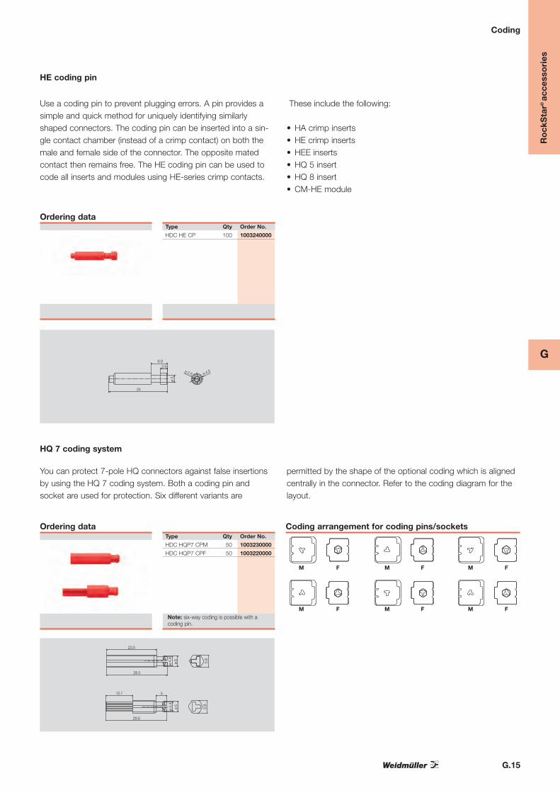
HE coding pin
Use a coding pin to prevent plugging errors. A pin provides asimple and quick method for uniquely identifying similarlyshaped connectors. The coding pin can be inserted into a sin-gle contact chamber (instead of a crimp contact) on both themale and female side of the connector. The opposite matedcontact then remains free. The HE coding pin can be used tocode all inserts and modules using HE-series crimp contacts.
These include the following:
• HA crimp inserts• HE crimp inserts• HEE inserts• HQ 5 insert• HQ 8 insert• CM-HE module
Ordering dataType Qty Order No.
HDC HE CP 100 1003240000
HQ 7 coding system
You can protect 7-pole HQ connectors against false insertionsby using the HQ 7 coding system. Both a coding pin and socket are used for protection. Six different variants are
permitted by the shape of the optional coding which is alignedcentrally in the connector. Refer to the coding diagram for thelayout.
Ordering dataType Qty Order No.
HDC HQP7 CPM 50 1003230000
HDC HQP7 CPF 50 1003220000
Note: six-way coding is possible with acoding pin.
23.5
28.5
ø 4.
4ø
5 5.9
24
6 92.9
ø 3
ø 2 6 ø 4.5
12.7
28.6
ø 4.
4ø
5
5.9
5
Coding arrangement for coding pins/sockets
M F M F M F
M F M F M F

G.16
G
Ro
ckS
tar®
acc
esso
ries
Adapter plates / Cover plates
Ordering data
Adapter plates, plastic
Type Size Qty Order No.orange
ADP-8/3-OR 3 10 1664980000
ADP-8/4-OR 4 10 1665000000
ADP-8/6-OR 6 10 1665020000
gray
ADP-8/3-GR 3 10 1664990000
ADP-8/4-GR 4 10 1665010000
ADP-8/6-GR 6 10 1665030000
Cover plates
Type Size Qty Order No.Sheet steel
ABD-1 sheet steel 1 10 9457300000
Plastic, gray
ABD-2-GR 2 10 1664330000
ABD-3-GR 3 10 1664350000
ABD-4-GR 4 10 1664360000
ABD-5-GR 5 10 1664370000
ABD-6-GR 6 10 1664390000
ABD-8-GR 8 10 1664970000Plastic, orange
ABD-8-OR 8 10 1664960000
Adapter plates, SUB-D
Type Aperture Qty Order No.Size 3 / Plastic
ADS/6-1/9 1 x SUB-D 9 10 1665940000
ADS/6-2/9 2 x SUB-D 9 10 1665950000
ADS/6-1/15 1 x SUB-D 15 10 1666200000
ADS/6-2/15 2 x SUB-D 15 10 1666210000
Size 4 / Plastic
ADS/10-1/25 1 x SUB-D 25 10 1666220000
ADS/10-2/25 2 x SUB-D 25 10 1666230000
Size 6 / Plastic
ADS/16-1/25 1 x SUB-D 25 10 1666320000
ADS/16-2/25 2 x SUB-D 25 10 1666330000
ADS/16-1/37 1 x SUB-D 37 10 1666340000
ADS/16-2/37 2 x SUB-D 37 10 1666350000
ADS/16-1/50 1 x SUB-D 50 10 1666460000
Adapter plates, plastic
Material PA6
Sealing material TPE-S
Color orange/gray
Temperature range –30 °C to +110 °C
Class of protection IP 65
Technical dataCover plates
Material PA6 / FE
Sealing material TPE-S
Color orange/gray
Temperature range –30 °C to +110 °C
Class of protection IP 65
Adapter plates, SUB-D
Material PA6
Sealing material
Color gray
Temperature range –30 °C to +110 °C
Class of protection

G.17
G
Ro
ckS
tar®
acc
esso
ries
Other accessories
Moulded gasket seals
Type Size Qty Order No.
HDC FLDG 04A 1 5 1044480000
HDC FLDG 06B 3 5 1044500000
HDC FLDG 10A 2 5 1044490000
HDC FLDG 10B 4 5 1044510000
HDC FLDG 16A 5 5 1044520000
HDC FLDG 16B 6 5 1044530000
HDC FLDG 24B 8 5 1044550000
HDC FLDG 32A 7 5 1044540000
HDC FLDG 32B 10 5 1044560000
HDC FLDG 48B 12 5 1044570000
HDC-HB10 AWVL FD HB-10 AWVL 500 1855680000
Note:for bulkhead housings
Gaskets
Ordering data Type Size Qty Order No.
HDC DG 06B 3 5 1044610000
HDC DG 07A 1 5 1044580000
HDC DG 10A 2 5 1044590000
HDC DG 10B 4 5 1044620000
HDC DG 16A 5 5 1044600000
HDC DG 16B 6 5 1044630000
HDC DG 24B 8 5 1044650000
HDC DG 32A 7 5 1044640000
HDC DG 48A 32B 9/10 5 1044660000
HDC DG 48B 12 5 1044670000
Note:for bulkhead and coupling housings

G.18
Other accessories
Type Qty Order No.
DSTV-TS 6 VH 10 1595230000
DSTV-TS 10-24 VH 10 1595240000
Note:For all inserts apart from HA and all inserts of size 1
Locking hook
Example: DSTV-TS
Type Qty Order No.
DSTV-TS 6-24 10 1595220000
Note:For all inserts apart from HA and all inserts of size 1
Locking foot for TS 35 mounting rail
G
Ro
ckS
tar®
acc
esso
ries

G.19
Other accessories
Technical data
Use Clamping of the shield
Fastening of shield lever To PE terminal, both sides, 2nd screw for fixing
Cable connection system Shield clamp or KLBÜ clamping yoke
No. shield clamps or KLBÜ clamping yokes
Size 3 (06B) 1* or 1
Size 4 (10B) 2* or 2
Size 6 (16B) 3* or 3
Size 8 (24B) 5* or 5
* Fastening points of shield clamp, 16 mm spacing
Clamping range shield clamp see page G.16
Material Steel
Surface Galvanized
Temperature range –40 ºC ... +125 ºC
Shield lever for sizes 3 (06B), 4 (10B), 6 (16B) and 8 (24B) for fitting of shield clamps or KLBÜ 3–8 SC
Type Size Qty Order No.
HDC SHIELD LEVER 3 SC 3 1 1867390000 20
16M4M3
4
33.5
44
28.5 12 17
34 +1 0
45
2
4 3
4 25
13 2 +0 3
HDC SHIELD LEVER 3 SC
Type Size Qty Order No.
HDC SHIELD LEVER 4 SC 4 1 1867370000
44
2016
4
15
32
47 +1 0
58
M4M3
17
33.5
2
4 3
4 25
13 2 +0 3
4
8.5
13
4HDC SHIELD LEVER 4 SC
Type Size Qty Order No.
HDC SHIELD LEVER 6 SC 6 1 1867380000
44
30
20
16
16
48
56
68 +1 0
79
M4M3
17
33.5
2
4 3
4 25
13 2 +0 3
4
8.5
13
4
HDC SHIELD LEVER 6 SC
Type Size Qty Order No.
HDC SHIELD LEVER 8 SC 8 1 1867360000
44
604830168
16404880
94 +1 0
M4M3
4
8
.5
13
1
733
.5
2
4 3
4 25
13 2 0 3
HDC SHIELD LEVER 8 SC
Shield leverfor standard inserts and the ConCept modular system (plastic frame)
Ro
ckS
tar®
acc
esso
ries
G
G.20
G
Ro
ckS
tar®
acc
esso
ries
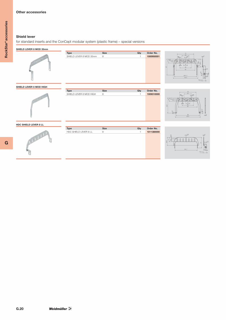
Other accessories
Type Size Qty Order No.
SHIELD LEVER 8 MOD 35mm 8 1 1000950001
80
17
67
45
93 5 +0 1 0
2
4 3
4 25
78.5
13 2 +0 1 0
104 5
48
164
70
30M3 M4
8 5
285
33.5
1.5
SHIELD LEVER 8 MOD 35mm
Type Size Qty Order No.
SHIELD LEVER 8 MOD HIGH 8 1 1009310000
80
14
637
2
7
105 5
48
164
7030
M3 M4
7
2.7 Ø 4
2
98
SHIELD LEVER 8 MOD HIGH
Type Size Qty Order No.
HDC SHIELD LEVER 8 LL 8 1 10113800003 8
17
33.5
44
94 +0 1 0
2
4 3
4 25
9.7
5.15
13 2 +0 3 0
HDC SHIELD LEVER 8 LL
Shield leverfor standard inserts and the ConCept modular system (plastic frame) – special versions

G.21
G
Ro
ckS
tar®
acc
esso
ries
Other accessories
Type Size Qty Order No.
SHIELD LEVER 8 MOD 8 1 1983940000
80
14
53
2
7
105 5
48
164
7030
M3 M4
7
2.7
Ø 4
.2
98
SHIELD LEVER 8 MOD
Type Size Qty Order No.
SHIELD LEVER 8 MOD HIGH 8 1 1009310000
80
14
63.7
2
7
105 5
48
164
7030
M3 M4
7
2.7 Ø 4
.2
98
SHIELD LEVER 8 MOD HIGH
Type Size Qty Order No.
SHIELD LEVER 3 MOD 3 1 1983910000
14
44
2
7
48
2016
M3
M4
2.7
Ø 4
.2
40 5
4
SHIELD LEVER 3 MOD
Type Size Qty Order No.
SHIELD LEVER 4 MOD 4 1 1983920000
1444
2
7
59 5
328M3
2.7
Ø 4
.2
52
7
SHIELD LEVER 4 MOD
Type Size Qty Order No.
SHIELD LEVER 6 MOD 6 1 1983930000
1444
2
7
82 5
48
8M3
2.7 Ø 4
.2
75
7
16
SHIELD LEVER 6 MOD
Shield leverfor the ConCept modular system (metal frame) – straight version

G.22
G
Ro
ckS
tar®
acc
esso
ries
Other accessories
Type Size Qty Order No.
SHIELD LEVER 8 CSB 45°L 8 1 1018760000
1453
7
298
70
M3
2.7
Ø 4
2
80
7
16
6 8
21.9
45°
7
30
48
105 5
M4
4
SHIELD LEVER 8 CSB 45°L
Shield leverfor the ConCept modular system (metal frame) – 45° angled version
Type Size Qty Order No.
SHIELD LEVER 3 CSB 45° 3 1 1017040000
14
44
2
48
20
M3
2.7 Ø 4
.2
40 5
7
164
M4
6 8
19.8
45°
SHIELD LEVER 3 CSB 45°
Type Size Qty Order No.
SHIELD LEVER 4 CSB 45° 4 1 1017050000
14
44
2
59 5
32M3
2.7 Ø 4
.2
52
7
8
6 8
19.8
45°7
SHIELD LEVER 4 CSB 45°
Type Size Qty Order No.
SHIELD LEVER 6 CSB 45° 6 1 1017060000
14
44
2
82 5
48
M3
2.7
Ø 4
.2
75
7
8
6 8
19.8
45°7
16
SHIELD LEVER 6 CSB 45°
Type Size Qty Order No.
SHIELD LEVER 8 CSB 45° 8 1 101707000014
63.7
298
70
M3
2.7
Ø 4
.2
80
7
16
6 8
31.9 45
7
30
48
105 5
M4
4
SHIELD LEVER 8 CSB 45°

G.23
G
Ro
ckS
tar®
acc
esso
ries
Other accessories
Technical data
Use Clamps shield on the shield lever
Fastening of shield lever With supplied fastening accessories
Clamping range shield clamp Cable diameter mm Gauge of fastening holes mm
Shield clamp 10 mm 10 20
Shield clamp 9 mm 9 20
Shield clamp 8 mm 8 20
Shield clamp 7 mm 7 20
Shield clamp 6 mm 6 16
Shield clamp 5 mm 5 16
Shield clamp 4.5 mm 4.5 16
Material Steel
Surface Galvanized
Temperature range –40 ºC ... +125 ºC
Shield clamps for shield levers of size 3 (06B), 4 (10B), 6 (16B) and 8 (24B)
Type Qty Order No.
SHIELD CLAMP 4.5 WO S 100 1018120000
SHIELD CLAMP 5 WO S 100 1018130000
SHIELD CLAMP 6 WO S 100 1018150000
SHIELD CLAMP 7 WO S 100 1018160000
SHIELD CLAMP 8 WO S 100 1018170000
SHIELD CLAMP 9 WO S 100 1018180000
SHIELD CLAMP 10 WO S 100 1018190000
SHIELD CLAMP 14 WO S 100 1041490000
Shield clamps
Type Qty Order No.
HDC SHIELD CLAMP 4.5 100 1912190000
HDC SHIELD CLAMP 5.0 100 1912200000
HDC SHIELD CLAMP 6.0 100 1912210000
HDC SHIELD CLAMP 7.0 100 1912220000
HDC SHIELD CLAMP 8.0 100 1912230000
HDC SHIELD CLAMP 9.0 100 1912240000
HDC SHIELD CLAMP 10.0 100 1912250000
HDC SHIELD CLAMP 14.0 1 1002820000
Shield contact clips with fitting materials

G.24
G
Ro
ckS
tar®
acc
esso
ries
Other accessories
Technical data
Use To establish direct contact to bulkhead
Fastened with integrated M5 screws
Advantages Broad contact surface gives large-area contact
Low contact resistance; high torsional rigidity
Shield can be connected to grip panel
Material data Grip Panel 8 SC
Material Steel
Surface Galvanized
Temperature range –40 °C to +125 °C
System data
Size 24B or 8
KLBÜ and shield clamps can be used
Cable ties can be used for fixing cable
HDC GRIP PANEL 8 SC
Type Qty Order No.
HDC GRIP PANEL 8 SC 5 1934770000
142
Ø 4 2
104
124135
100
8
M3
M5
Grip panel
Type Qty Order No.
HDC FIXING SCREW M3x10 50 1029510000
HDC PE CONCEPT SCREW M4 50 1029460000
HDC PE HD SCREW M4x6 50 1029440000
HDC PE HDD SCREW M4x6.5 50 1029450000
HDC PE HSB SCREW M5x6.8 50 1029490000
HDC PE S SCREW M5x8 50 1029470000
HDC PE S6/6 SCREW M4x8 50 1029520000
PE screws