Embed Size (px)
Citation preview

Page 1
Contents of LGT-306E Precedent Electric Light Kit(You will need LGT-306H sub harness in conjunction with LGT-306E for installation on a Precedent Gas Golf Car)
a. Headlight Bumper assemblyb. (2) LED Tail light assembliesc. (1) Wiring harness w/ Push Pull switchd. (1) Fuse Wire assemblye. (6) Zip ties (not pictured)f. (1) Installation Manual (not Picture)
Caution: Before starting this project, remove the system positive & negative connections from the battery or battery pack and place tow run switch inthe tow position on electric vehicles. Please readthrough the instructions carefully.
Harness Installation: Picture 11. Remove the three Torx head screws that secure the instrument panel and remove the panel from the
dash.2. Locate the indentation to the right of the key switch on the instrument panel and drill a 7/16" hole
for the push pull headlight switch.3. Remove the knob, retaining nut and washer from the push pull head light switch. Insert the shaft of
the switch into the hole in the instrument panel and secure using the washer and nut and reattachthe knob.
4. Plug the 12 pin male Precedent light harness connector into the 12 pin Female connector on themain vehicle harness and wire tie to existing instrument panel control harness.
5. Route the 6 pin headlight connector through the cutout in the passenger dash.6. Reinstall the instrument panel being cautious to not pinch any wiring.7. Remove the front bumper, save existing hardware as it will be used to install the new bumper/
headlight assembly.8. Plug the 6 pin male wire harness connector into the 6 pin female headlight wire harness connector
and wire tie harness to frame support. (The two extra wires on this harness are for use with theoptional horn kit )
9. Install the bumper/headlight assembly using the original mounting hardware.

Page 2
Taillight Installation: Picture 2Before removing double sided tape and installing theLED tail lights test fit them in their position on the reargolf car body. The tail lights will rest on the rear underbody and line up with the edge of the bag well.
1. On each side of the rear body measure 21⁄4 inchesover from the vertical body line and mark a verticalline. Measure 11⁄2 inches up from the under bodyand mark a horizontal line. Mark this location with acenter punch.
2. Using a 11⁄2 inch hole saw drill a hole in the locations marked in step one. Sand the edge outsideof the holes to remove sharp edges.
3. Clean thoroughly the surface area where taillight will be mounted with rubbing alcohol. (this willensure the double sided tape will adhere properly)
4. Reach inside the hole and pull the taillight connector through the hole in the rear body.5. Connect the taillights to the vehicle taillight wire harness.6. Remove the double sided tape and mount to the rear body. (Be sure of your mounting location
before you remove double sided tape and adhere to vehicle)
Picture 1
Picture 2
11⁄2"
21⁄4"
BodyLine
3 Pin Horn Connector
Route 6 Pin Connector toWheel Well Area Here
Optional Disconnectfor Voltage Reducer
Installation
12 Pin Male LightHarness Connector
12 Pin Female Connectorfrom Main Vehicle Harness
Page 3
Fuse assembly instillation : Picture 3(For gas vehicles please see LGT-306H sub harness installation instructions.)
12 Volt Battery Installation (for vehicle without DC to DC converter)1. Remove the seat bottom and the electronic component cover located between the batteries.2. Locate the blue wire coming off the #4 battery positive connection (Picture 3) and connect to the
long lead of the fuse assembly.3. Locate the single 12 gauge blue wire with a spade terminal coming from the passenger side of the
electronic component area and connect the short lead coming from the fuse assembly.4. Secure all loose wires. 5. Install electronic component cover and you’re ready to go.
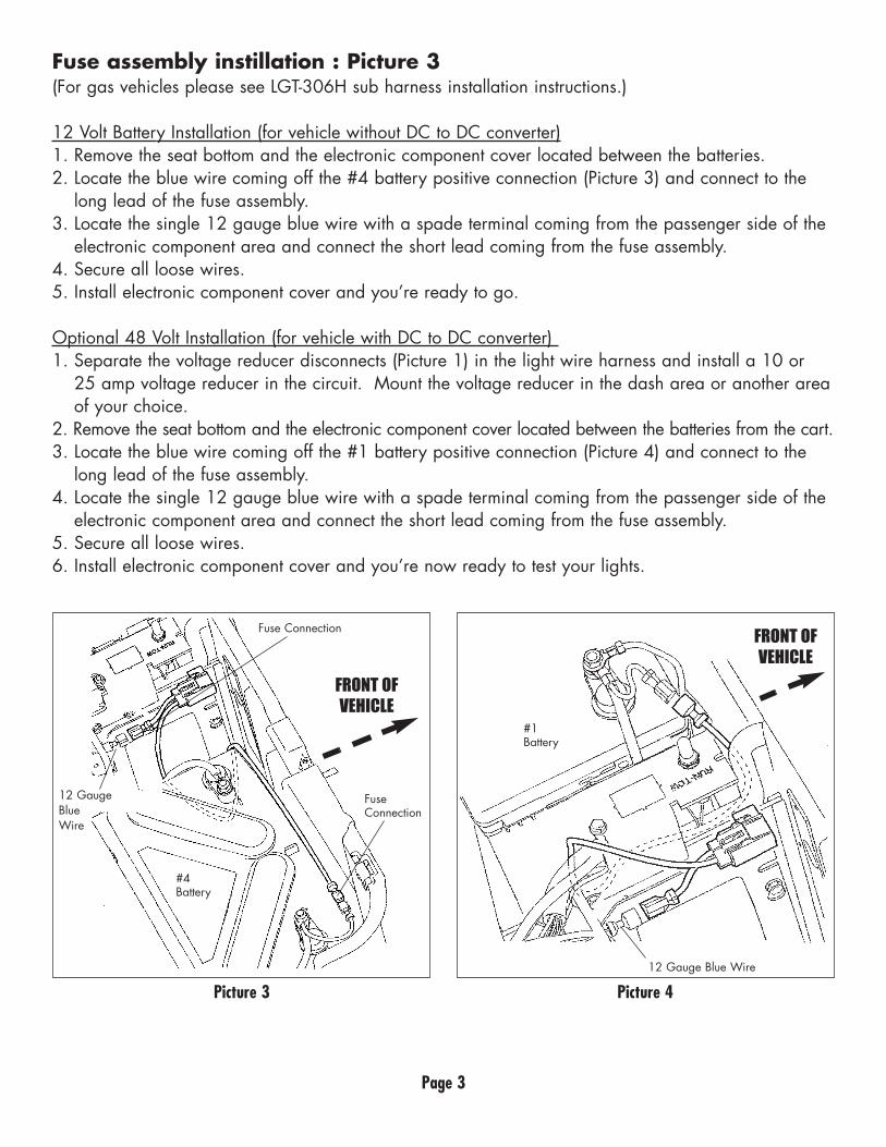
Optional 48 Volt Installation (for vehicle with DC to DC converter) 1. Separate the voltage reducer disconnects (Picture 1) in the light wire harness and install a 10 or
25 amp voltage reducer in the circuit. Mount the voltage reducer in the dash area or another areaof your choice.
2. Remove the seat bottom and the electronic component cover located between the batteries from the cart. 3. Locate the blue wire coming off the #1 battery positive connection (Picture 4) and connect to the
long lead of the fuse assembly.4. Locate the single 12 gauge blue wire with a spade terminal coming from the passenger side of the
electronic component area and connect the short lead coming from the fuse assembly.5. Secure all loose wires. 6. Install electronic component cover and you’re now ready to test your lights.
Picture 3 Picture 4
FRONT OFVEHICLE
FRONT OFVEHICLE
Fuse Connection
12 GaugeBlueWire
12 Gauge Blue Wire
Fuse Connection
#4Battery
#1Battery