Embed Size (px)
DESCRIPTION
sws
Citation preview
ME-416
STRESS ANALYSIS

Instructor: Dr. Khalid Rahman
Room No. G11 (FME Faculty Lobby)
Tel: 2351
Email: [email protected]
Teaching Assistant: Engr. Malik Abdul Wahab
◦ Engr. Umer
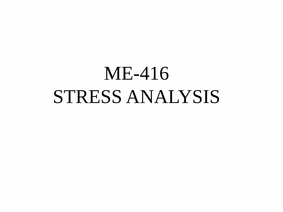
Text book:
•“Advanced Mechanics of Materials” 6th Edition by Arthur P. Boresi and Richard J. Schmidt
Reference book:
“Advanced Strength and Applied Stress Analysis” 2nd Edition by Richard G. Budynas
Course Material
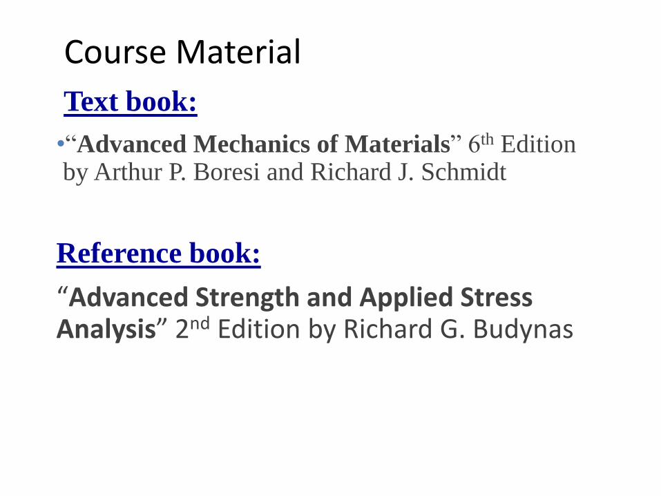
COURSE LEARNING OUTCOME (CLOs)
CLO NO
CLO STATEMENT Upon Completion of the course student should be able to:
PLO Bloom Taxonomy
CLO1 Demonstrate the understanding of stress and strain from
the simple problems of state of stress at a point PLO2 C2
CLO2 Demonstrate the ability to apply the criterion for failure
in the design of structural members. PLO3 C3
CLO3 Analyze stresses on unsymmetrical beams, non-circular
shaft, thick wall cylinders and rotating disk. PLO2 C4
CLO4
Demonstrate the understating of advanced topics in
Stress Analysis (Stress Concentrations, Fracture
Mechanics, Fatigue).
PLO2 C3
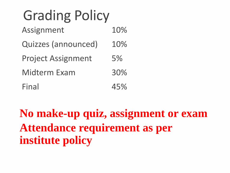
Grading Policy Assignment 10%
Quizzes (announced) 10%
Project Assignment 5%
Midterm Exam 30%
Final 45%
No make-up quiz, assignment or exam
Attendance requirement as per institute policy
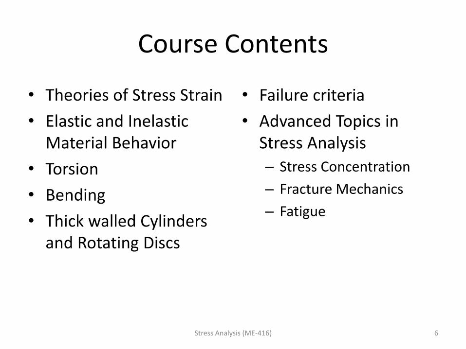
Course Contents
• Theories of Stress Strain
• Elastic and Inelastic Material Behavior
• Torsion
• Bending
• Thick walled Cylinders and Rotating Discs
• Failure criteria
• Advanced Topics in Stress Analysis
– Stress Concentration
– Fracture Mechanics
– Fatigue
Stress Analysis (ME-416) 6
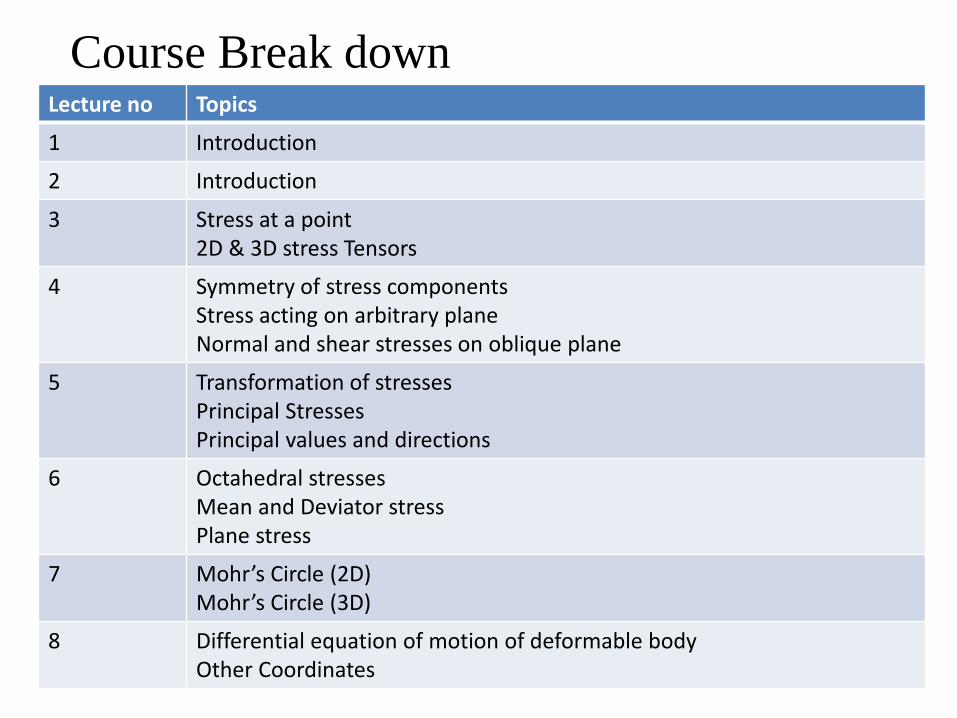
Course Break down Lecture no Topics
1 Introduction
2 Introduction
3 Stress at a point 2D & 3D stress Tensors
4 Symmetry of stress components Stress acting on arbitrary plane Normal and shear stresses on oblique plane
5 Transformation of stresses Principal Stresses Principal values and directions
6 Octahedral stresses Mean and Deviator stress Plane stress
7 Mohr’s Circle (2D) Mohr’s Circle (3D)
8 Differential equation of motion of deformable body Other Coordinates
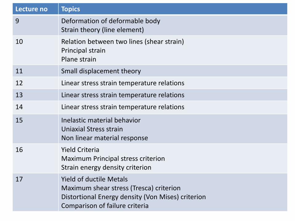
Lecture no Topics
9 Deformation of deformable body Strain theory (line element)
10 Relation between two lines (shear strain) Principal strain Plane strain
11 Small displacement theory
12 Linear stress strain temperature relations
13 Linear stress strain temperature relations
14 Linear stress strain temperature relations
15 Inelastic material behavior Uniaxial Stress strain Non linear material response
16 Yield Criteria Maximum Principal stress criterion Strain energy density criterion
17 Yield of ductile Metals Maximum shear stress (Tresca) criterion Distortional Energy density (Von Mises) criterion Comparison of failure criteria
Lecture no Topics
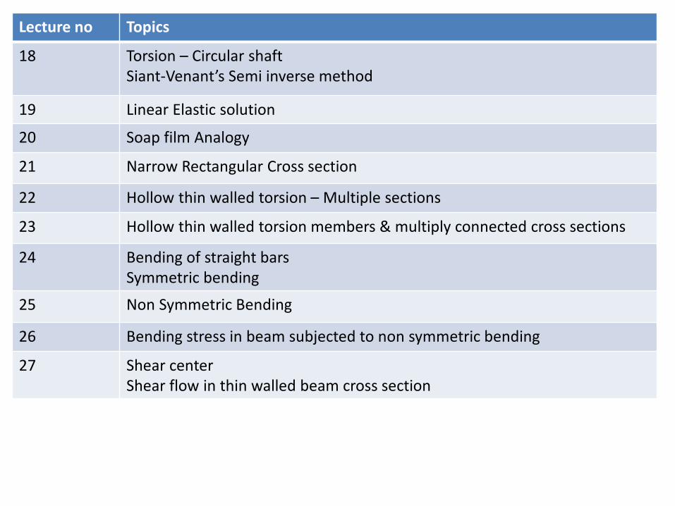
18 Torsion – Circular shaft Siant-Venant’s Semi inverse method
19 Linear Elastic solution
20 Soap film Analogy
21 Narrow Rectangular Cross section
22 Hollow thin walled torsion – Multiple sections
23 Hollow thin walled torsion members & multiply connected cross sections
24 Bending of straight bars Symmetric bending
25 Non Symmetric Bending
26 Bending stress in beam subjected to non symmetric bending
27 Shear center Shear flow in thin walled beam cross section
Lecture no Topics
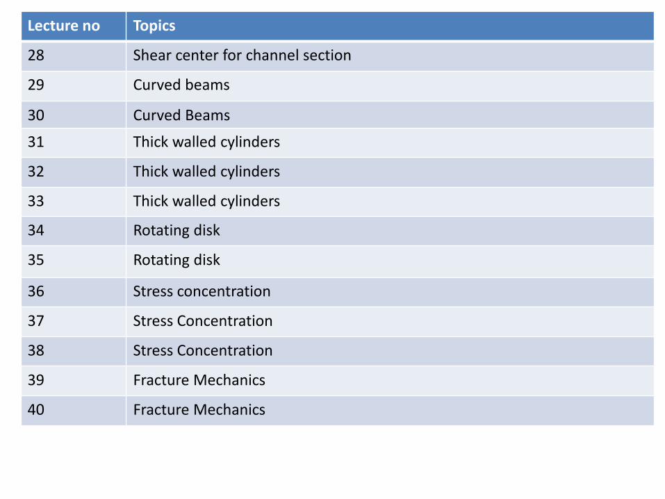
28 Shear center for channel section
29 Curved beams
30 Curved Beams
31 Thick walled cylinders
32 Thick walled cylinders
33 Thick walled cylinders
34 Rotating disk
35 Rotating disk
36 Stress concentration
37 Stress Concentration
38 Stress Concentration
39 Fracture Mechanics
40 Fracture Mechanics
Lecture no Topics
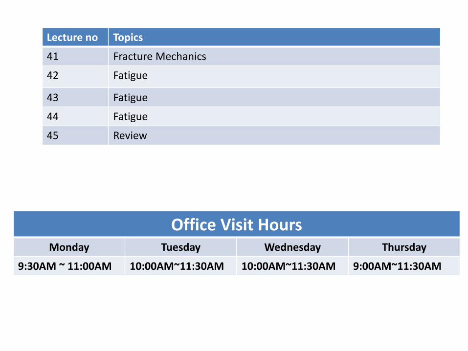
41 Fracture Mechanics
42 Fatigue
43 Fatigue
44 Fatigue
45 Review
Office Visit Hours Monday Tuesday Wednesday Thursday
9:30AM ~ 11:00AM 10:00AM~11:30AM 10:00AM~11:30AM 9:00AM~11:30AM

Assignment Session, Project and Quiz Schedule Assignment Session and Quiz at FME QUIZ HALL (Time: 10:00 AM)
Assignment Sessions
1 15th Sept 2015
2 13th Oct 2015
3 3rd Nov 2015
4 17th Nov 2015
5 1st Dec 2015
6 15th Dec 2015
Quiz Schedule
1 8th Sept 2015
2 20th Sept 2015
3 10th Nov 2015
4 8th Dec 2015
Project Assignment due Date 11th Dec 2015
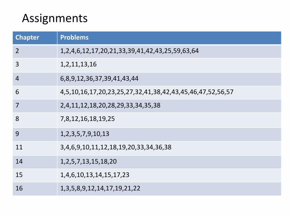
Chapter Problems
2 1,2,4,6,12,17,20,21,33,39,41,42,43,25,59,63,64
3 1,2,11,13,16
4 6,8,9,12,36,37,39,41,43,44
6 4,5,10,16,17,20,23,25,27,32,41,38,42,43,45,46,47,52,56,57
7 2,4,11,12,18,20,28,29,33,34,35,38
8 7,8,12,16,18,19,25
9 1,2,3,5,7,9,10,13
11 3,4,6,9,10,11,12,18,19,20,33,34,36,38
14 1,2,5,7,13,15,18,20
15 1,4,6,10,13,14,15,17,23
16 1,3,5,8,9,12,14,17,19,21,22
Assignments
Concept • The main objective of the study of Stress Analysis is to
provide the future engineer with the means of analyzing
and designing various machines and load bearing
structures.
• Both the analysis and design of a given structure involve the
determination of
•Stresses
•deformations
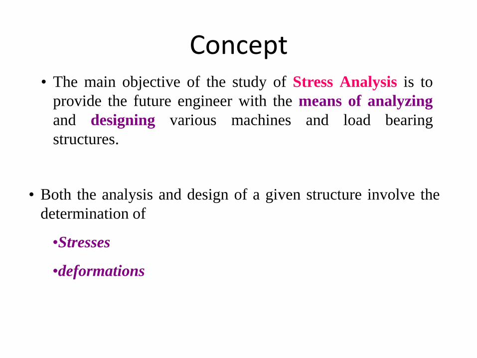
Introduction Any material or structure may
fail when it is loaded
Stress Analysis (ME-416) 15
1 Strength – The structure must be strong enough to carry the applied loads. 2 Stiffness – The structure must be stiff enough such that only allowable deformation occurs. 3 Stability – The structure must not collapse through buckling subjected to the applied compressive loads.
Stress analysis provides analytical, numerical and or experimental methods for determining the strength, stiffness and stability of load-carrying structural members
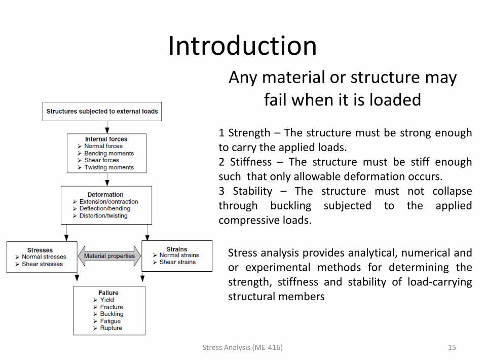
Examples
Stress Analysis (ME-416) 16
Stent expansion process
Artery after stent inflation
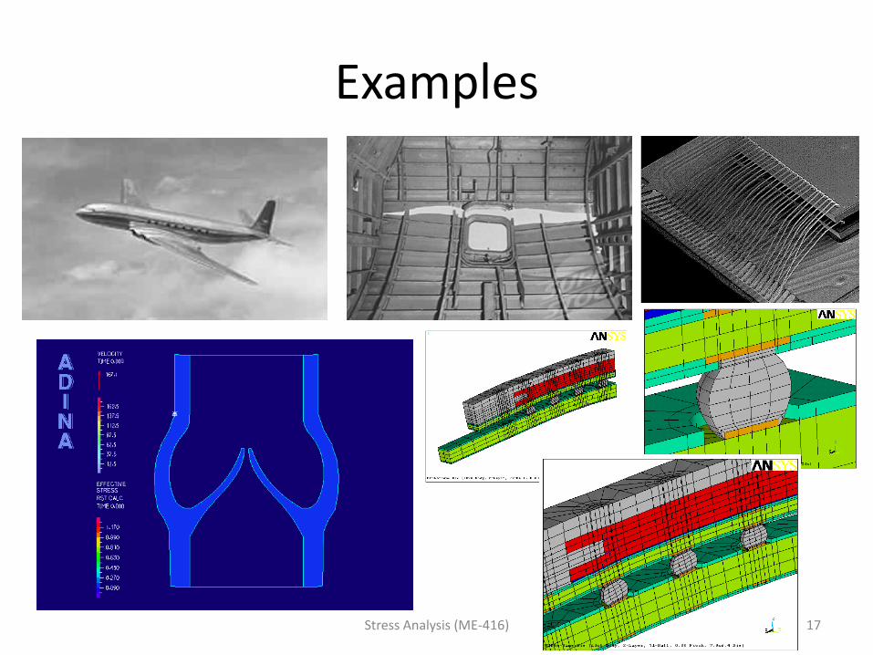
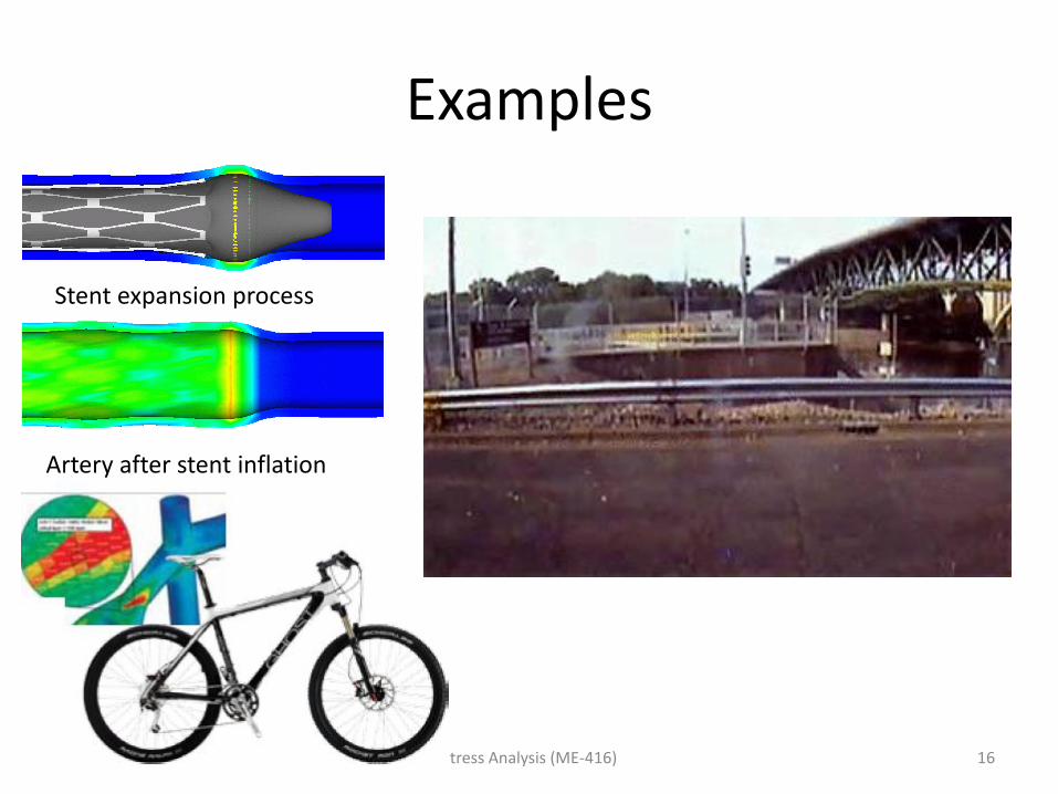
Examples
Stress Analysis (ME-416) 17
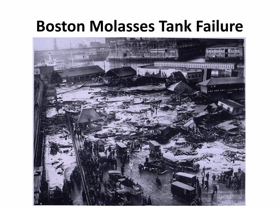
Boston Molasses Tank Failure
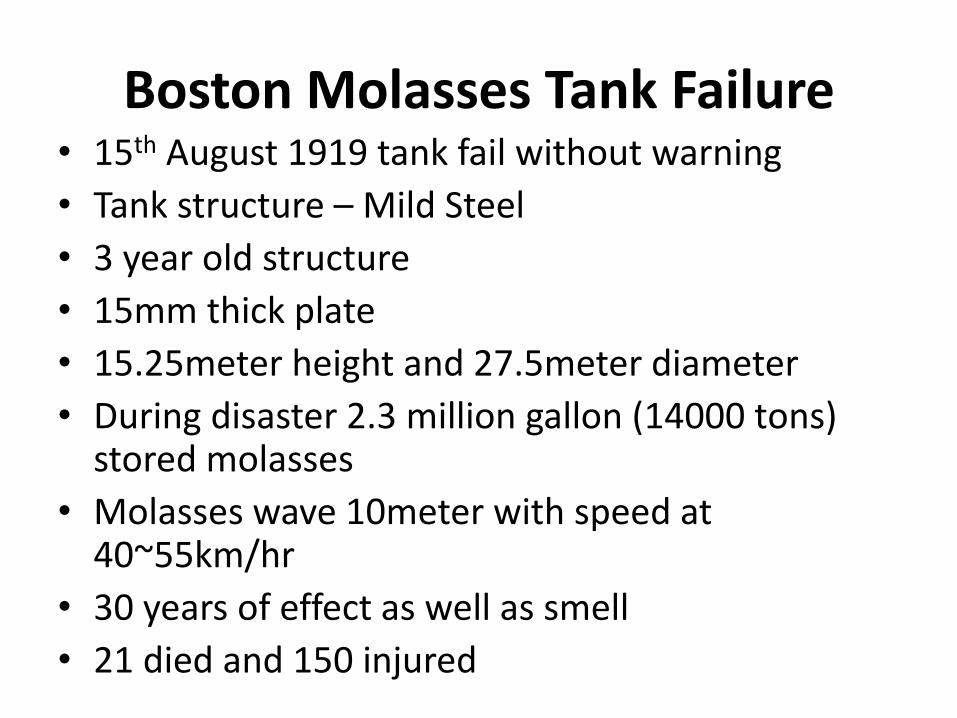
Boston Molasses Tank Failure • 15th August 1919 tank fail without warning
• Tank structure – Mild Steel
• 3 year old structure
• 15mm thick plate
• 15.25meter height and 27.5meter diameter
• During disaster 2.3 million gallon (14000 tons) stored molasses
• Molasses wave 10meter with speed at 40~55km/hr
• 30 years of effect as well as smell
• 21 died and 150 injured
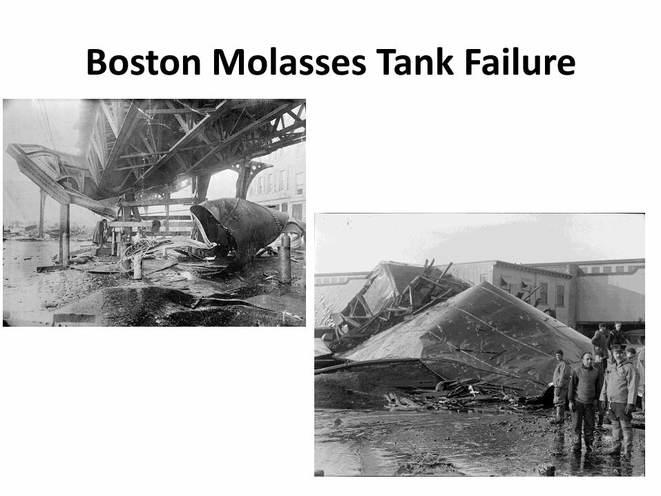
Boston Molasses Tank Failure
Boston Molasses Tank Failure
• Leakage in the tank (manhole) was ignored and painted brown
• Failure due to sudden temperature change from -17⁰C (previous day) to 4.5⁰C on day of failure
• Investigation – Design was inadequate to withstand pressure and factor of safety was low
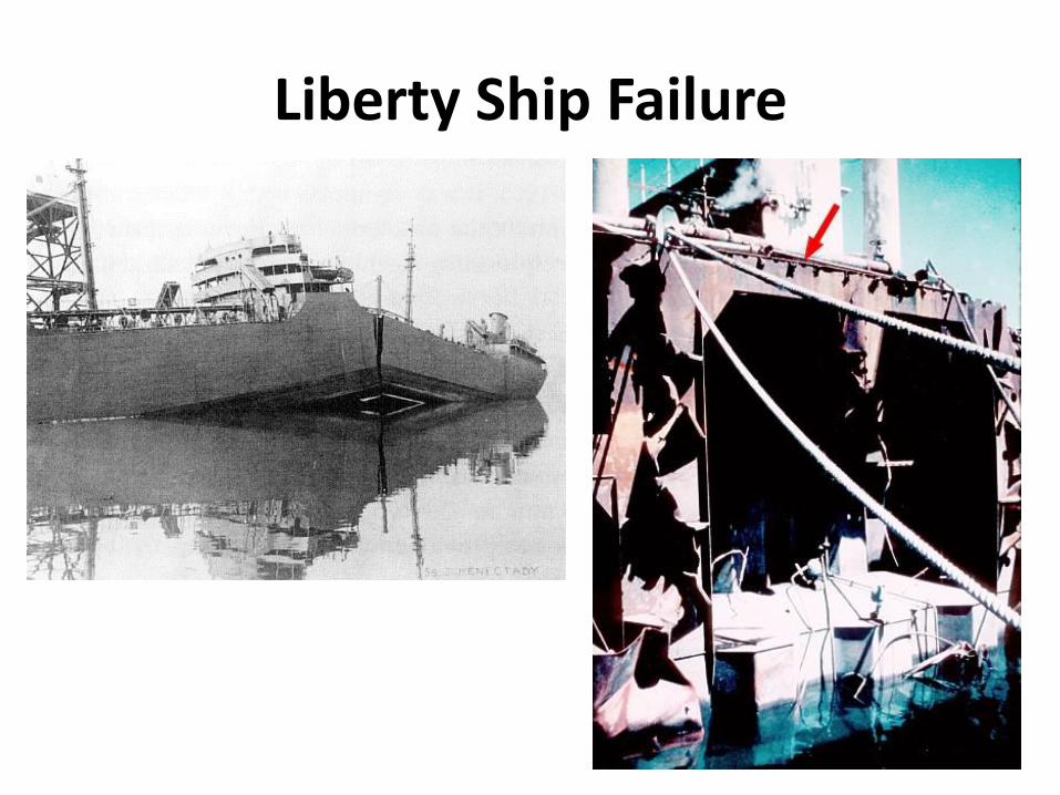
Liberty Ship Failure

Liberty Ship Failure
• Initially ship building – mostly riveted joint
• WW-II mass production
• These ships first to have all welded joint
• 2700 Liberty ships were mass produced (some in 5 days)
• 1000 suffered significant failure
• Some broke suddenly into two because of low temperature
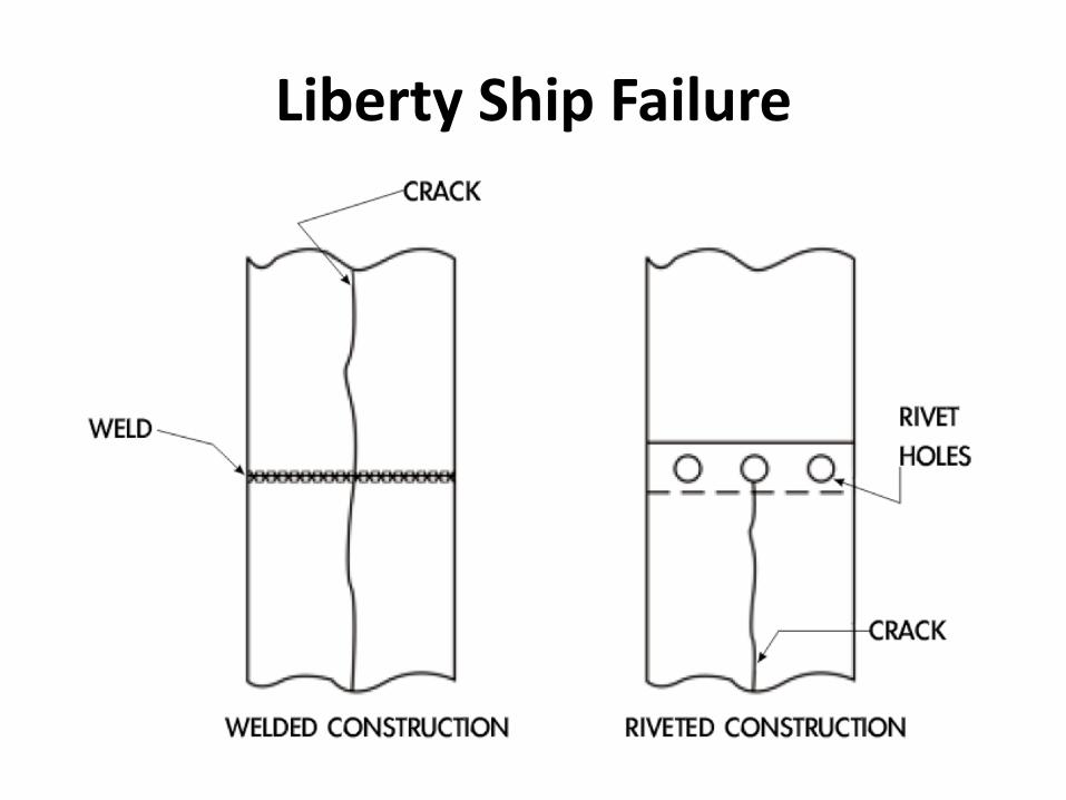
Liberty Ship Failure
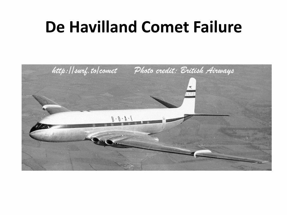
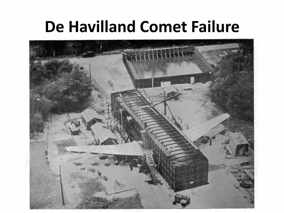
De Havilland Comet Failure
De Havilland Comet Failure
• World’s first commercial jetliner into service in 1952
• Previously propeller planes – low altitude
• During first year of service – 28000 passengers and 104 million miles
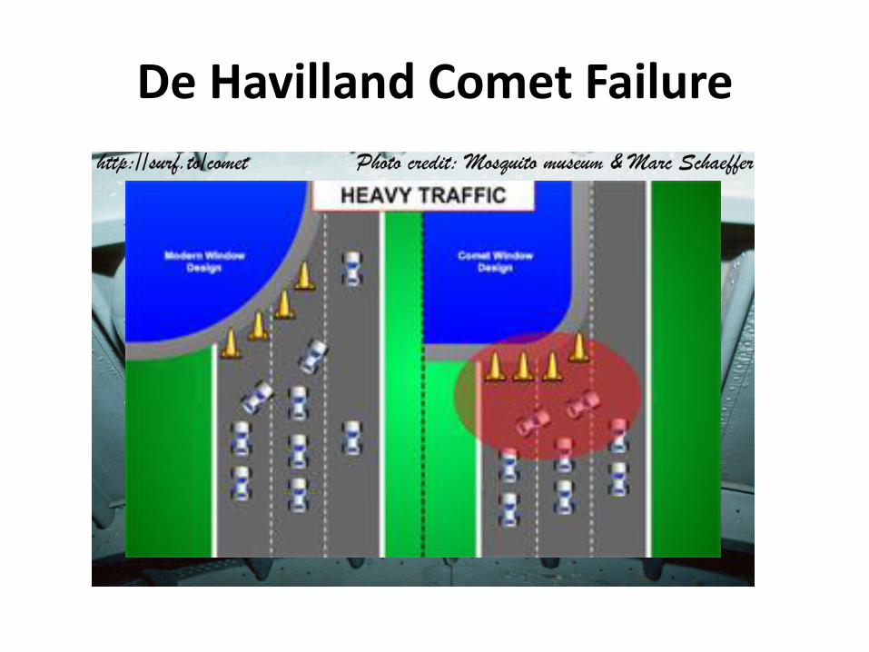
• US Civil Aeronautics Administration has refused to grant Comet airworthiness certificate. Reason Stress concentration
• Large size crew escape window
De Havilland Comet Failure
De Havilland Comet Failure
De Havilland Comet Failure
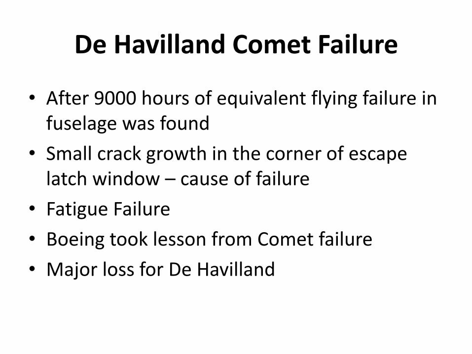
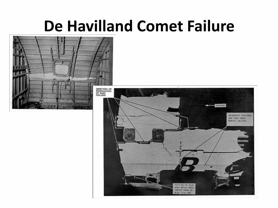
• After 9000 hours of equivalent flying failure in fuselage was found
• Small crack growth in the corner of escape latch window – cause of failure
• Fatigue Failure
• Boeing took lesson from Comet failure
• Major loss for De Havilland
De Havilland Comet Failure
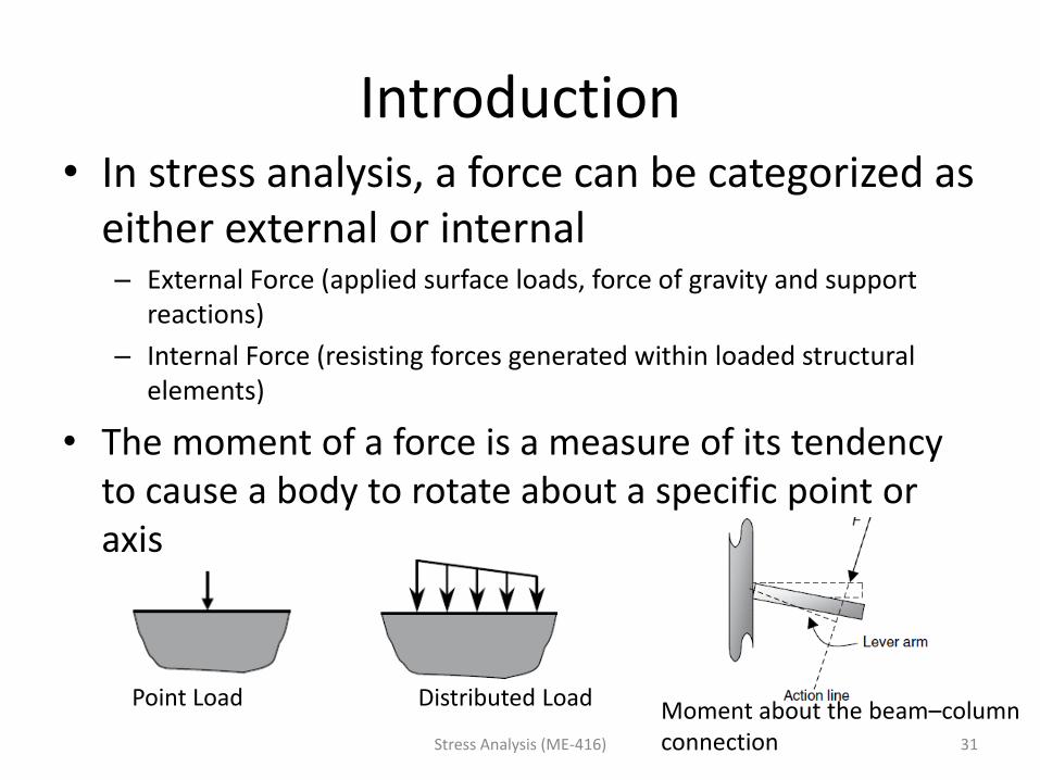
Introduction • In stress analysis, a force can be categorized as
either external or internal – External Force (applied surface loads, force of gravity and support
reactions)
– Internal Force (resisting forces generated within loaded structural elements)
• The moment of a force is a measure of its tendency to cause a body to rotate about a specific point or axis
Stress Analysis (ME-416) 31
Point Load Distributed Load Moment about the beam–column connection
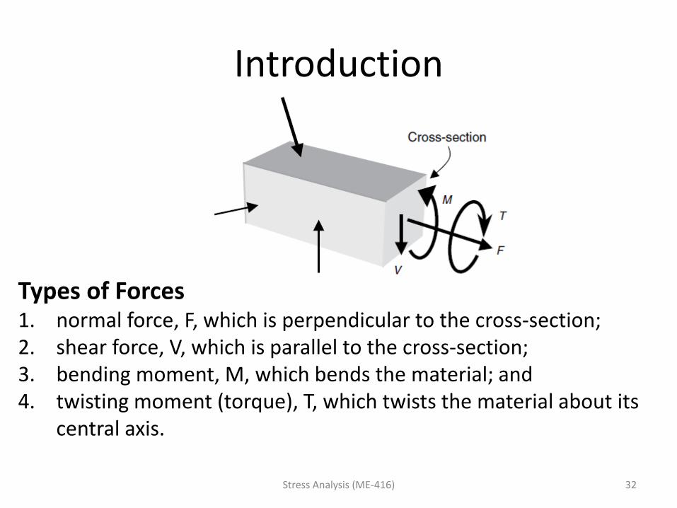
Introduction
Stress Analysis (ME-416) 32
Types of Forces 1. normal force, F, which is perpendicular to the cross-section; 2. shear force, V, which is parallel to the cross-section; 3. bending moment, M, which bends the material; and 4. twisting moment (torque), T, which twists the material about its
central axis.
Introduction
Equilibrium system 1. the resultant of all applied forces, including support
reactions, must be zero;
2. the resultant of all applied moments, including bending and twisting moments, must be zero.
The two equilibrium conditions are commonly used to determine support reactions and internal forces on cross-sections of structural members.
Stress Analysis (ME-416) 33
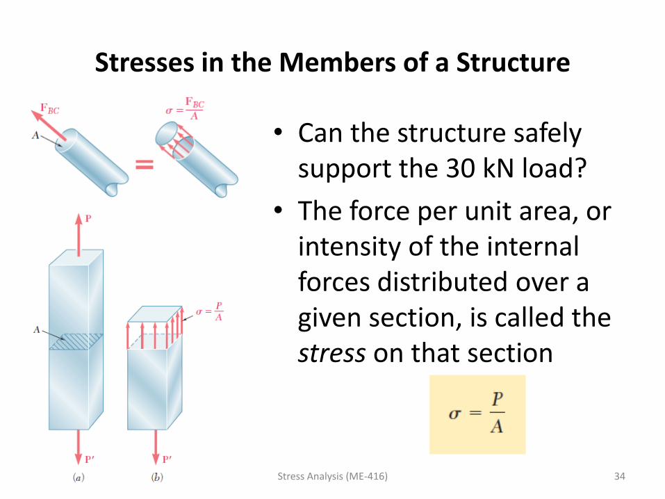
Stresses in the Members of a Structure
• Can the structure safely support the 30 kN load?
• The force per unit area, or intensity of the internal forces distributed over a given section, is called the stress on that section
Stress Analysis (ME-416) 34
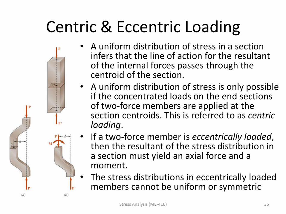
Centric & Eccentric Loading • A uniform distribution of stress in a section
infers that the line of action for the resultant of the internal forces passes through the centroid of the section.
• A uniform distribution of stress is only possible if the concentrated loads on the end sections of two-force members are applied at the section centroids. This is referred to as centric loading.
• If a two-force member is eccentrically loaded, then the resultant of the stress distribution in a section must yield an axial force and a moment.
• The stress distributions in eccentrically loaded members cannot be uniform or symmetric
Stress Analysis (ME-416) 35
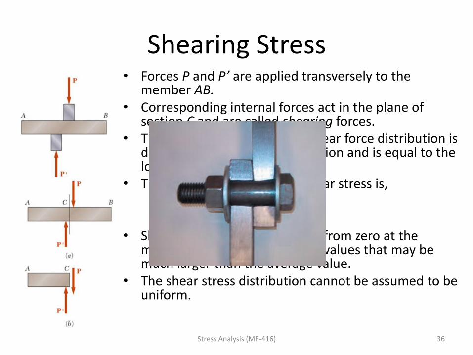
Shearing Stress • Forces P and P’ are applied transversely to the
member AB. • Corresponding internal forces act in the plane of
section C and are called shearing forces. • The resultant of the internal shear force distribution is
defined as the shear of the section and is equal to the load P.
• The corresponding average shear stress is,
• Shear stress distribution varies from zero at the member surfaces to maximum values that may be much larger than the average value.
• The shear stress distribution cannot be assumed to be uniform.
Stress Analysis (ME-416) 36
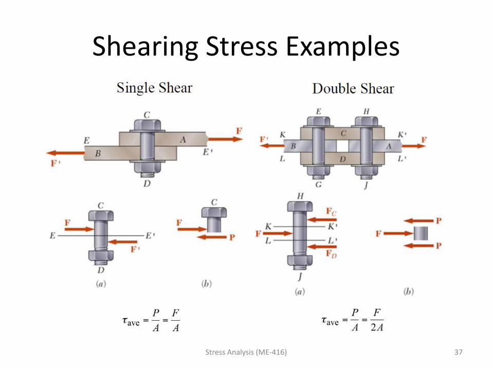
Shearing Stress Examples
Stress Analysis (ME-416) 37
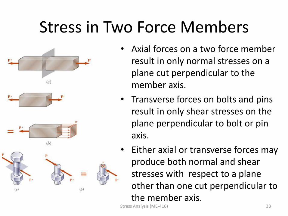
Stress in Two Force Members • Axial forces on a two force member
result in only normal stresses on a plane cut perpendicular to the member axis.
• Transverse forces on bolts and pins result in only shear stresses on the plane perpendicular to bolt or pin axis.
• Either axial or transverse forces may produce both normal and shear stresses with respect to a plane other than one cut perpendicular to the member axis.
Stress Analysis (ME-416) 38
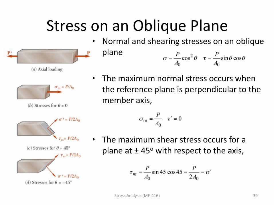
Stress on an Oblique Plane • Normal and shearing stresses on an oblique
plane
• The maximum normal stress occurs when the reference plane is perpendicular to the member axis,
• The maximum shear stress occurs for a plane at ± 45o with respect to the axis,
Stress Analysis (ME-416) 39
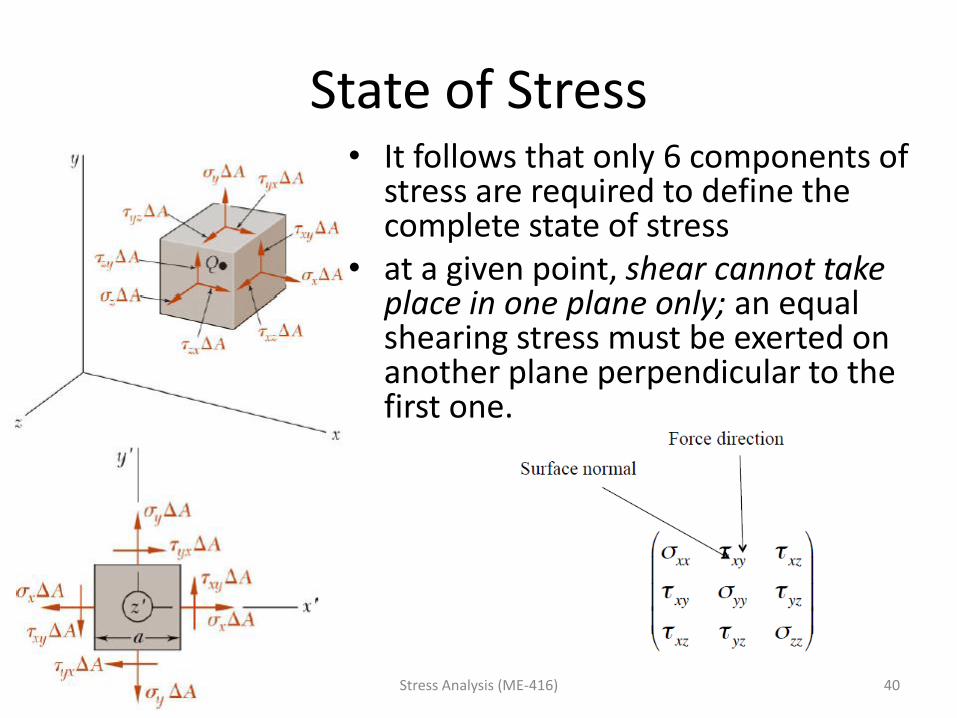
State of Stress • It follows that only 6 components of
stress are required to define the complete state of stress
• at a given point, shear cannot take place in one plane only; an equal shearing stress must be exerted on another plane perpendicular to the first one.
Stress Analysis (ME-416) 40
Generalized Hooke’s Law
L3-4 - 41
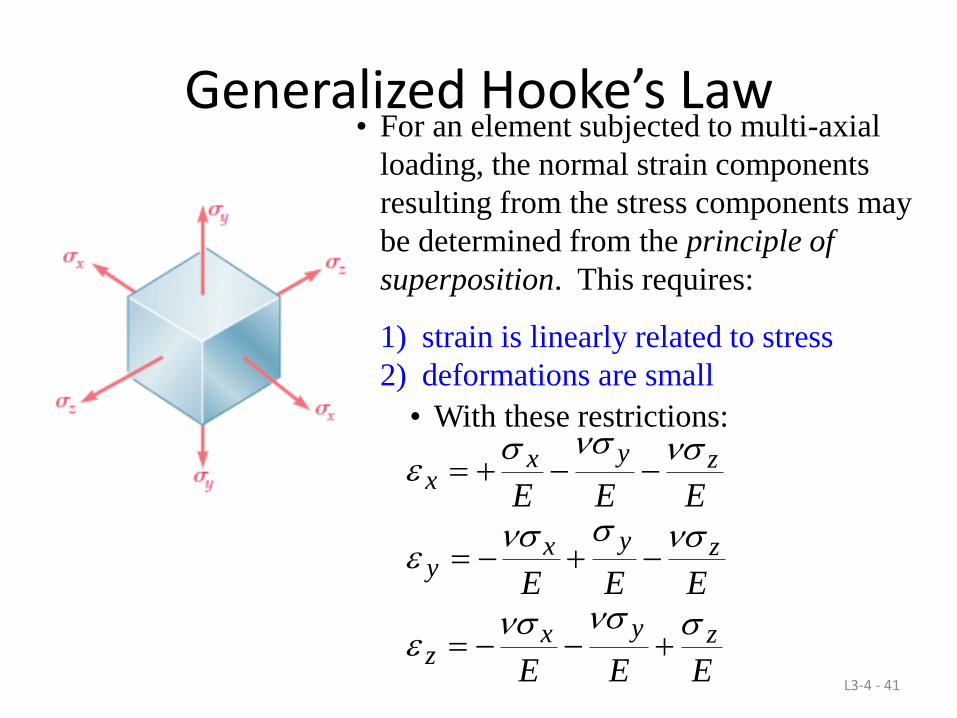
• For an element subjected to multi-axial
loading, the normal strain components
resulting from the stress components may
be determined from the principle of
superposition. This requires:
1) strain is linearly related to stress
2) deformations are small
EEE
EEE
EEE
zyxz
zyxy
zyxx
• With these restrictions:
SHEARING STRAIN
Stress Analysis (ME-416) 42
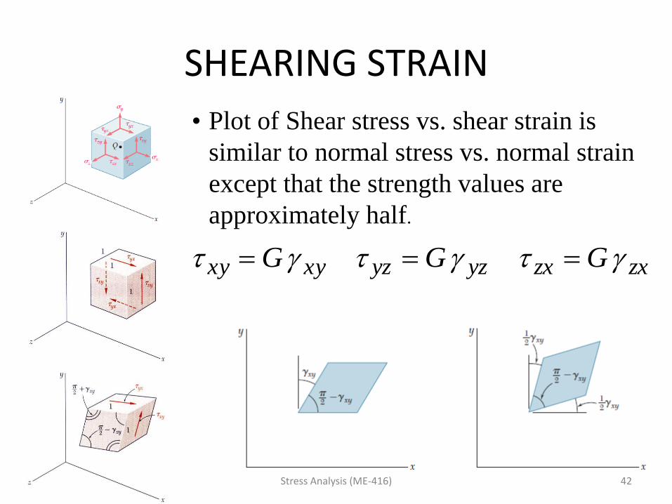
• Plot of Shear stress vs. shear strain is
similar to normal stress vs. normal strain
except that the strength values are
approximately half.
zxzxyzyzxyxy GGG
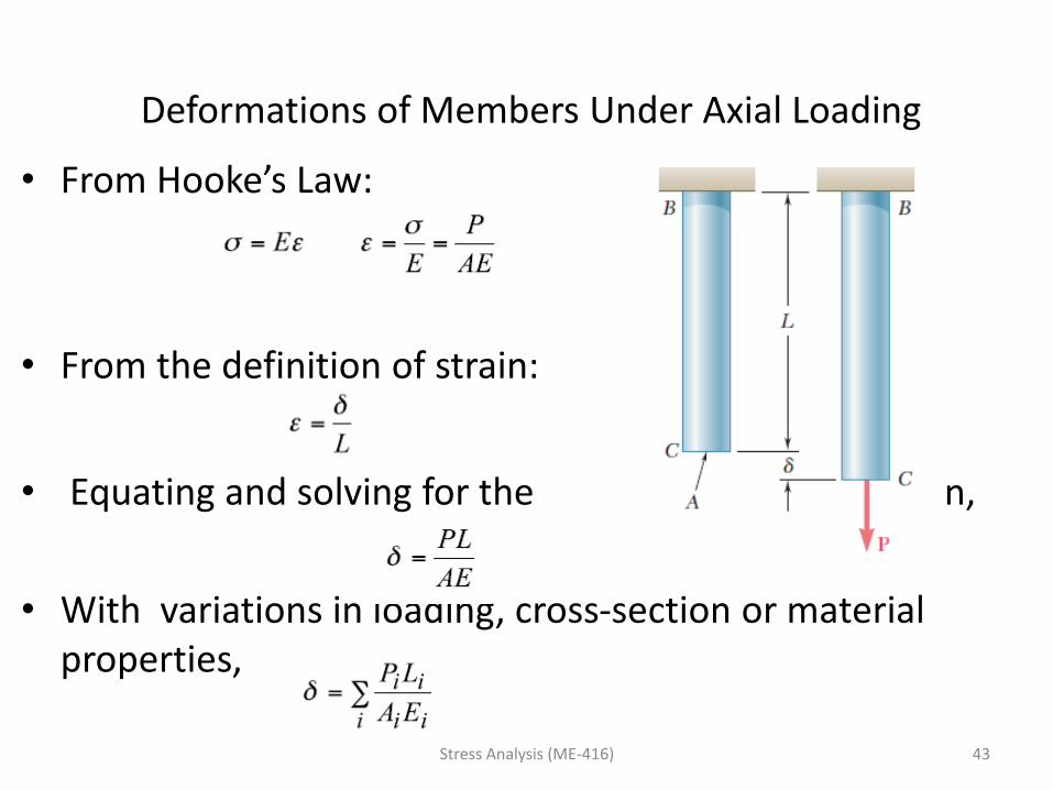
Deformations of Members Under Axial Loading
• From Hooke’s Law:
• From the definition of strain:
• Equating and solving for the deformation,
• With variations in loading, cross-section or material properties,
Stress Analysis (ME-416) 43
6 - 44
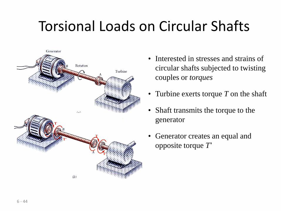
Torsional Loads on Circular Shafts
• Interested in stresses and strains of
circular shafts subjected to twisting
couples or torques
• Generator creates an equal and
opposite torque T’
• Shaft transmits the torque to the
generator
• Turbine exerts torque T on the shaft
6 - 45
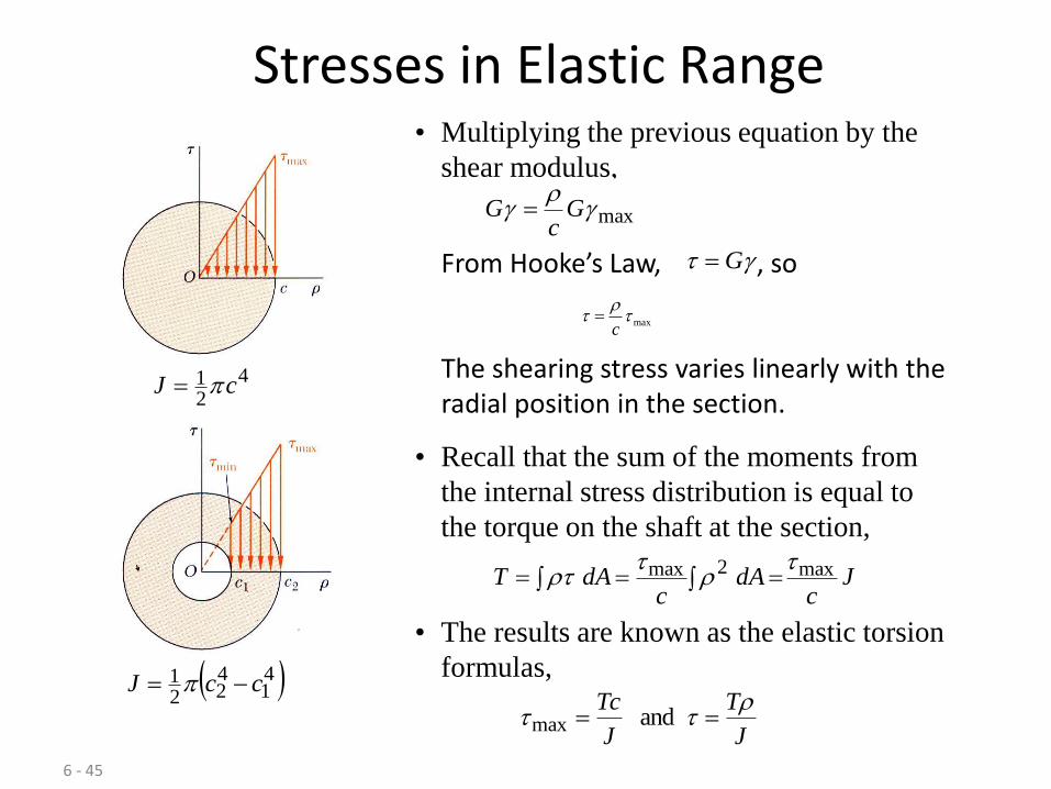
Stresses in Elastic Range
Jc
dAc
dAT max2max
• Recall that the sum of the moments from
the internal stress distribution is equal to
the torque on the shaft at the section,
421 cJ
41
422
1 ccJ
and maxJ
T
J
Tc
• The results are known as the elastic torsion
formulas,
• Multiplying the previous equation by the
shear modulus,
max
Gc
G
max
c
From Hooke’s Law, G , so
The shearing stress varies linearly with the radial position in the section.
6 - 46
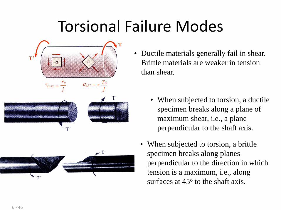
Torsional Failure Modes
• Ductile materials generally fail in shear.
Brittle materials are weaker in tension
than shear.
• When subjected to torsion, a ductile
specimen breaks along a plane of
maximum shear, i.e., a plane
perpendicular to the shaft axis.
• When subjected to torsion, a brittle
specimen breaks along planes
perpendicular to the direction in which
tension is a maximum, i.e., along
surfaces at 45o to the shaft axis.

7 - 47
Pure Bending
Pure Bending: Prismatic members
subjected to equal and opposite couples
acting in the same longitudinal plane

7 - 48
Other Loading Types
• Principle of Superposition: The normal
stress due to pure bending may be
combined with the normal stress due to
axial loading and shear stress due to shear
loading to find the complete state of stress.
• Eccentric Loading: Axial loading which
does not pass through section centroid
produces internal forces equivalent to an
axial force and a couple
• Transverse Loading: Concentrated or
distributed transverse load produces
internal forces equivalent to a shear force
and a couple
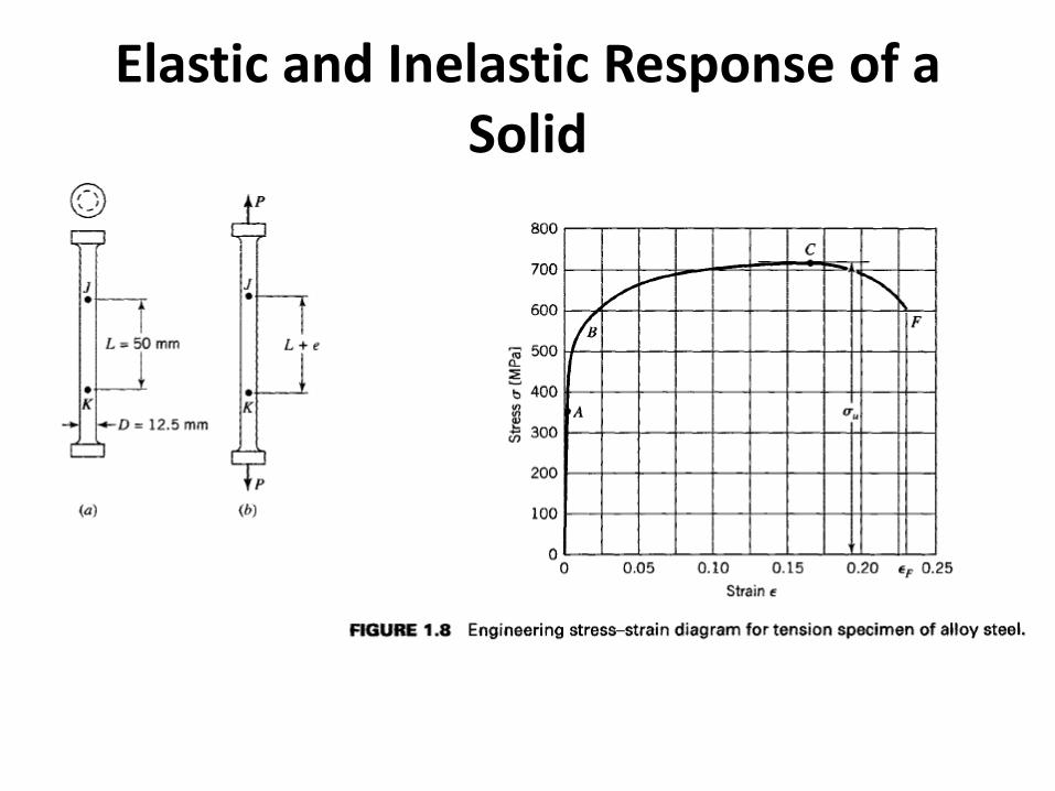
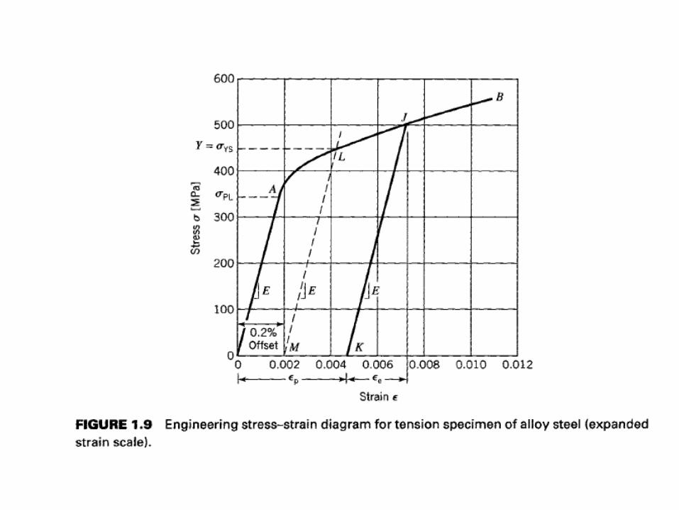
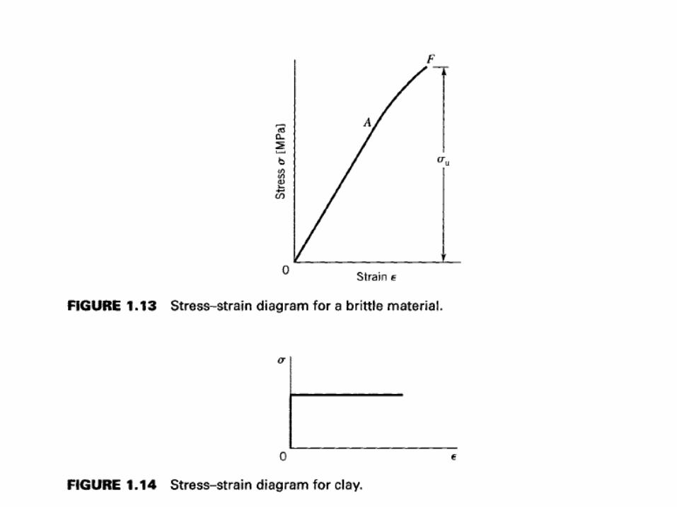
Elastic and Inelastic Response of a Solid
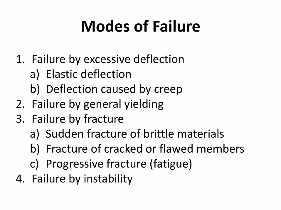
Modes of Failure
1. Failure by excessive deflection a) Elastic deflection b) Deflection caused by creep
2. Failure by general yielding 3. Failure by fracture
a) Sudden fracture of brittle materials b) Fracture of cracked or flawed members c) Progressive fracture (fatigue)
4. Failure by instability