Embed Size (px)
Citation preview


Contents
Safety
Emergency
Controls
Driving
Maintenance
Information
Index
1
2
3
4
5
6
7
Contents
©2012 Paccar Inc - All Rights Reserved
This manual illustrates and describes the operation of features or equipment which may be either standard or optional onthis vehicle. This manual may also include a description of features and equipment which are no longer available or werenot ordered on this vehicle. Please disregard any illustrations or descriptions relating to features or equipment which arenot on this vehicle.
PACCAR reserves the right to discontinue, change specifications, or change the design of its vehicles at any time withoutnotice and without incurring any obligation.
The information contained in this manual is proprietary to PACCAR. Reproduction, in whole or in part, by any means is strictlyprohibited without prior written authorization from PACCAR Inc.

Truck Model Example
i

SAFETY
INTRODUCTIONAbout This Manual . . . . . . . . . . . . . . . 1-3Safety Alerts . . . . . . . . . . . . . . . . . . 1-3Vehicle Safety . . . . . . . . . . . . . . . . . 1-5A Special Word About Repairs . . . . . . . . . . 1-8Additional Sources of Information . . . . . . . . . 1-9
CAB AND FRAME ACCESSSafety . . . . . . . . . . . . . . . . . . . . 1-10Door Lock and Keys. . . . . . . . . . . . . . 1-11Remote Keyless Entry (RKE) . . . . . . . . . . 1-12Climbing Onto the Deck Plate . . . . . . . . . 1-13
GETTING TO YOUR ENGINEHood Hold Downs. . . . . . . . . . . . . . . 1-15Hood Tilt . . . . . . . . . . . . . . . . . . . 1-16Hood Hold-Open Device . . . . . . . . . . . . 1-17
1-1
1

SAFETY
SEATS AND RESTRAINTSIntroduction . . . . . . . . . . . . . . . . . 1-19Safety Restraint Belts . . . . . . . . . . . . . 1-20Tether Belts . . . . . . . . . . . . . . . . . 1-22Komfort-Lok® Feature . . . . . . . . . . . . . 1-23During Pregnancy. . . . . . . . . . . . . . . 1-24Belt Damage and Repair . . . . . . . . . . . . 1-25Sleeper Bunks and Restraints . . . . . . . . . 1-25Safety Restraint Tips . . . . . . . . . . . . . 1-28
START-UPIntroduction . . . . . . . . . . . . . . . . . 1-30Safe Vehicle Operation . . . . . . . . . . . . 1-30Vehicle Loading. . . . . . . . . . . . . . . . 1-31Emergency Equipment . . . . . . . . . . . . 1-33Driver's Check List . . . . . . . . . . . . . . 1-33
1-2
1

INTRODUCTION
INTRODUCTION
About This Manual
Congratulations! Your selection of aKenworth truck was a wise investment.Kenworth trucks are recognized asthe industry standard for quality andreliability.
Please take the time to get acquaintedwith your vehicle by reading thisOperator’s Manual. We recommendthat you read and understand thismanual from beginning to end beforeyou operate your truck. This manualexplains the safe, efficient operationand maintenance of your Kenworth.
NOTEAfter you’ve read this manual, itshould be stored in the cab forconvenient reference and remainwith this truck when sold.
Your Kenworth may not have all thefeatures or options mentioned in thismanual. Therefore, you should paycareful attention to the instructions thatpertain to just your vehicle. In addition,if your vehicle is equipped with specialequipment or options not discussed inthis manual, consult your dealer or themanufacturer of the equipment.
All information contained in thismanual is based on the latestproduction information available at thetime of publication. Kenworth TruckCompany reserves the right to makechanges at any time without notice.
Safety Alerts
Please read and follow all of thesafety alerts contained in this manual.They are there for your protectionand information. These alerts canhelp you avoid injury to yourself, yourpassengers, and help prevent costlydamage to the vehicle. Safety alertsare highlighted by safety alert symbolsand signal words such as "WARNING","CAUTION", or "NOTE". Please do notignore any of these alerts.
1-3
1

INTRODUCTION
WARNING
WARNING
The safety message following thissymbol and signal word provides awarning against operating procedureswhich could cause death or personalinjury. They could also causeequipment or property damage. Thealert will identify the hazard, how toavoid it, and the probable consequenceof not avoiding the hazard.
Example:
WARNING
Do not carry additional fuelcontainers in your vehicle. Fuelcontainers, either full or empty,may leak, explode, and cause orfeed a fire. Do not carry extra fuelcontainers. Even empty ones aredangerous. Failure to comply mayresult in death or personal injury.
CAUTION
CAUTION
The safety alert following this symboland signal word provides a cautionagainst operating procedures whichcould cause equipment or propertydamage. The alert will identify thehazard, how to avoid it, and theprobable consequence of not avoidingthe hazard.
Example:
CAUTION
Continuing to operate your vehiclewith insufficient oil pressure willcause serious engine damage.Failure to comply may result inequipment or property damage.
1-4
1

INTRODUCTION
NOTE
NOTE
The alert following this symbol andsignal word provides importantinformation that is not safety relatedbut should be followed. The alertwill highlight things that may not beobvious and is useful to your efficientoperation of the vehicle.
Example:
NOTEPumping the accelerator will notassist in starting the engine.
Vehicle Safety
WARNING
Do not drink alcohol and drive. Yourreflexes, perceptions, and judgmentcan be affected by even a smallamount of alcohol. You could havea serious or even fatal accident,if you drive after drinking. Pleasedo not drink and drive or ride witha driver who has been drinking.Failure to comply may result indeath, personal injury, equipment orproperty damage.
WARNING
Do not text and drive. Your reactiontime, perceptions and judgment canbe affected while texting or usingany other form of mobile messagingwhile driving. Failure to complymay result in death, personal injury,equipment or property damage.
Make sure your vehicle is in topworking condition before headingout on the road, it is the responsibledriver's duty to do so. Inspect thevehicle according to the Driver's CheckList beginning on page 1-33.
Every new vehicle is designed toconform to all Federal Motor VehicleSafety Standards applicable at the timeof manufacture. Even with these safetyfeatures, continued safe and reliableoperation depends greatly uponregular vehicle maintenance. Followthe maintenance recommendationsfound in Preventive Maintenance onpage 5-9. This will help preserve yourinvestment.
Keep in mind that even a wellmaintained vehicle must be operatedwithin the range of its mechanicalcapabilities and the limits of its loadratings. See the Weight Ratings labelon the driver's door edge.
1-5
1

INTRODUCTION
Safe driving is only possible with theproper concentration on the drivingtask. Keep distraction to a minimum toimprove your concentration. Examplesof distractions may include radiocontrols, GPS navigation controls,cellular telephone calls, cellular textmessages, reading or reaching forsomething on the floor. Minimizingyour distractions will improve safedriving and will help avoid an accidentinvolving death or personal injury.
Be aware of local regulations that mayprohibit the use of cellular telephoneswhile driving. In addition to being anunsafe practice, it may be against localor federal ordinances to use cellulardevices while operating the vehicle.
This manual is not a training manual.It cannot tell you everything you needto know about driving your vehicle. Forthat you need a good training programor truck driving school. If you have not
been trained, get the proper trainingbefore you drive. Only qualified driversshould drive this vehicle.
California Proposition 65Warning• Diesel engine exhaust and some
of its constituents are known tothe State of California to causecancer, birth defects, and otherreproductive harm.
• Other chemicals in this vehicleare also known to the State ofCalifornia to cause cancer, birthdefects or other reproductiveharm.
• Battery posts, terminals, andrelated accessories contain leadand lead compounds, chemicalsknown to the State of Californiato cause cancer and reproductiveharm. Wash hands after handling.
1-6
1

INTRODUCTION
Data Recorder
California Vehicle Code - Section9951- Disclosure of Recording Device
Your vehicle may be equipped with oneor more recording devices commonlyreferred to as “event data recorders(EDR)” or “sensing and diagnosticmodules (SDM)”. If you are involved inan accident, the device(s) may havethe ability to record vehicle data thatoccurred just prior to and/or during theaccident. For additional information onyour rights associated with the use ofthis data, contact
• the California Department of MotorVehicles - Licensing OperationsDivision– or –
• http://www.dmv.ca.gov/pubs/vctop/d03_6/vc9951.htm
Environmental Protection
WARNING
Diesel engine exhaust and someof its constituents are known tothe State of California to causecancer, birth defects, and otherreproductive harm. Other chemicalsin this vehicle are also known to theState of California to cause cancer,birth defects or other reproductiveharm. This warning requirementis mandated by California law(Proposition 65) and does not resultfrom any change in the manner inwhich vehicles are manufactured.
Some of the ingredients in engineoil, hydraulic oil, transmission andaxle oil, engine coolant, diesel fuel,air conditioning refrigerant (R12,R134a, and PAG oil), batteries, etc.,may contaminate the environment ifspilled or not disposed of properly.Contact your local government agency
for information concerning properdisposal.
1-7
1

INTRODUCTION
A Special Word AboutRepairs
WARNING
Do not attempt repair work withoutsufficient training, service manuals,and the proper tools. You could bekilled or injured, or you could makeyour vehicle unsafe. Do only thosetasks you are fully qualified to do.
Your dealer’s service center is the bestplace to have your vehicle repaired.You can find dealers all over thecountry with the equipment and trainedpersonnel to get you back on the roadquickly—and keep you there.
Your vehicle is a complex machine.Anyone attempting repairs on it needsgood mechanical training and theproper tools. If you are sure youhave these requirements, then youcan probably perform some repairsyourself. However, all warranty repairs
must be performed by an authorizedservice facility. If you aren’t anexperienced mechanic, or don’t havethe right equipment, please leave allrepairs to an authorized service facility.They are the ones equipped to do thejob safely and correctly.
Maintenance Manuals. If you dodecide to do any complex repair work,you’ll need the maintenance manuals.Order them from your authorizeddealer. Please provide your ChassisSerial Number when you order, to besure you get the correct manuals foryour vehicle. Allow about four weeksfor delivery. There will be a charge forthese manuals.
Final Chassis Bill of Material. Acomplete, non-illustrated computerprintout listing of the parts used tocustom-build your vehicle is availablethrough the dealer from whom youpurchased your vehicle.
WARNING
Modifying your vehicle can makeit unsafe. Some modificationscan affect your vehicle's electricalsystem, stability, or other importantfunctions. Before modifying yourvehicle, check with your dealer tomake sure it can be done safely.Improper modifications can causedeath or personal injury.
1-8
1

INTRODUCTION
Additional Sources ofInformationInstalled Equipment -Operator's Manuals
Major component suppliers also supplyoperation manuals specific to theirproducts. Additional manuals andother pieces of literature are includedin the glove box literature package.Look for information on productssuch as the engine, driver's seat,transmission, axles, wheels, tires,ABS/ESP (if applicable), radio, 5thwheel, lane departure and adaptivecruise control. If you are missing thesepieces of literature, ask your Dealerfor copies.
Other Sources
Another place to learn more abouttrucking is from local truck drivingschools. Contact one near you to learnabout courses they offer.
Federal and state agencies suchas the department of licensing alsohave information. The InterstateCommerce Commission can giveyou information about regulationsgoverning transportation across statelines.
1-9
1

CAB AND FRAME ACCESS
CAB AND FRAMEACCESS
Safety
WARNING
Always reinstall steps beforeentering the cab or accessing thedeck plate. Without steps you couldslip and fall. Failure to comply mayresult in death or personal injury.
Be careful whenever you get into or outof your vehicle’s cab. Always maintainat least three points of contact withyour hands on the grab handles andyour feet on the steps.
WARNING
Jumping out of the cab or gettinginto the cab without proper cautionis dangerous. You could slip andfall, which could lead to death orpersonal injury. Keep steps clean.Clean any fuel, oil, or grease off ofthe steps before entering the cab.Use the steps and grab handlesprovided, and always keep at leastthree points of contact betweenyour hands and feet and the truck.Always face toward the vehiclewhen entering or exiting the cab andlook where you are going.
The following picture shows the bestway to enter and exit a ConventionalCab.
1-10
1

CAB AND FRAME ACCESS
Door Lock and KeysDoor Lock
Doors can be locked from the inside byusing the lock button. Close the doorthen push the button down to lock.Doors automatically unlock when youopen them from inside, and can belocked from the outside with the key orthe optional remote keyless entry keyfob.
WARNING
To reduce the chance of death orpersonal injury, always lock thedoors while driving. Along withusing the lap shoulder belts properly,locking the doors helps preventdoors from inadvertently openingand occupants from being ejectedfrom the vehicle.
To lock or unlock the doors fromoutside the cab, insert the key in thelock. Turn the key toward the rear tolock; forward to unlock.
Keys
The same key fits your ignition, doors,and sleeper luggage compartment.
Frame-mounted tool box locks andlocking fuel tank caps each haveindividual keys.
1-11
1

CAB AND FRAME ACCESS
Remote Keyless Entry (RKE)(Optional)
This vehicle may be equipped with aRemote Keyless Entry (RKE) systemthat adds security and convenienceto your vehicle. The system willlock or unlock the driver’s door andpassenger’s door with the key fob andalert you with parking lights when theselected doors are locked or unlocked.The system includes two key fobs thatprovide secure rolling code technologythat prevents someone from recordingthe entry signal.
NOTEFCC ID: L2C0031T IC:3432A-0031T FCC ID: L2C0032RIC: 3432A-0032R This devicecomplies with Part 15 of the FCCRules and with RSS-210 of IndustryCanada. Operation is subjectto the following two conditions:(1) This device may not causeharmful interference, and (2) Thisdevice must accept any interferencereceived, including interference thatmay cause undesired operation.Changes or modifications notexpressively approved by the partyresponsible for compliance couldvoid the user's authority to operatethe equipment. The term “IC:”before the radio certification numberonly signifies that Industry Canadatechnical specifications were met.
OperationTo Unlock The Driver’s Door
Press the UNLOCK button once. Thedriver's door will unlock and the parkinglights will come on for 40 seconds.
To Unlock The Passenger’sDoor
Press the UNLOCK button once andpress again within 5 seconds. Thepassenger door will unlock.
To Lock All Doors
Press the LOCK button. The doors willlock and the parking lights will comeon for 2 seconds. If the doors are openthey will not lock. The range of theRKE system should be approximately30 ft. This will be reduced if it isoperated close to other RF sourcessuch as TV/radio transmitters and celltowers.
1-12
1

CAB AND FRAME ACCESS
Batteries
The key fob uses one CR2032,3V battery. Batteries should lastapproximately three years, dependingon use. Consistently reduced rangeis an indicator that the battery needsreplacement. Batteries are availableat most discount, hardware and drugstores.
The battery can be accessed byremoving the cover of the key fob.After a new battery is installed, thekey fob must be synchronized with thevehicle.
Synchronization
The key fob may need to besynchronized to the truck when thebattery is replaced or when the key fobhas not been used for an extendedperiod of time.
To Synchronize A Key Fob1. Hold the key fob near the receiver
which is located behind thespeedometer and tachometer.
2. Press and hold both the Lock andUnlock buttons at the same timefor approximately 7 seconds.
3. When the key fob isresynchronized, the doorswill lock then immediately unlock.
4. If the fob fails to synchronize,it could be programmed to adifferent truck or could have failed.Contact your dealer to re-programyour key fob.
Climbing Onto the DeckPlate
WARNING
When you are climbing onto andoff the deck plate, maintain at leastthree points of contact with yourhands on the grab handles andyour feet on the steps. Always facetoward the vehicle when entering orexiting the cab and look where youare going. Failure to comply mayresult in death or personal injury.
WARNING
When stepping onto a surface toenter the cab or access the deckplate, only use the steps and grabhandles installed and designed forthat purpose. Failure to use theproper steps and grabhandles couldcause a fall which may result indeath or personal injury.
1-13
1

CAB AND FRAME ACCESS
WARNING
Keep steps clean. Clean any fuel,oil, or grease off the steps beforeentering the cab or accessing thedeck plate. Stepping on a slipperysurface can cause a fall which mayresult in death or personal injury.
WARNING
Always reinstall steps beforeentering the cab or accessing thedeck plate. Without steps you couldslip and fall. Failure to comply mayresult in death or personal injury.
NOTEAny alteration (adding bulkheads,headache racks, tool boxes, etc.)behind the cab that affects theutilization of installed grab handles,deck plates, or frame access stepsshould comply with Federal MotorCarrier Safety Regulation 399.
The following pictures show you theright way to get on and off the areabehind your cab.
Hold handles as you step up.
Maintain three points of contact.
1-14
1

GETTING TO YOUR ENGINE
GETTING TO YOURENGINE
Hood Hold Downs
Hood hold downs keep a hood fromopening unexpectedly.
CAUTIONA hood not latched securely couldopen during operation and causevehicle damage. Be sure to latchthe hood securely.
1. Hood Latch in the Closed Position
1-15
1

GETTING TO YOUR ENGINE
2. Pull Latch to Open 3. Pull Up to SeparateHood Tilt
To open your hood, unlock the hoodhold downs by unlatching them. Putone or both hands on the top of thehood front. Tilt the hood forward bypulling at the top of the hood, pivotingon the foot placed on the bumperand using the foot on the ground forstability. Keep pulling on the hooduntil you are certain that the hood holdopen device is engaged. When closingthe hood, be sure that you maintainthe same points of contact (top of hoodand bumper) to control the movementof the hood as it closes.
WARNING
A pivoting hood could hurt someoneor be damaged itself. Beforeopening or closing the hood, be surethere are no people or objects in theway. Failure to stand in a position ofsafety can cause death or personalinjury.
1-16
1

GETTING TO YOUR ENGINE
Pull with hand from here
Hood Hold-Open Device
The hood is equipped with a hoodhold-open device. In order for the hoodhold-open device to become engaged,the vehicle hood must be fully open.Once the vehicle hood is fully open,the hold-open latch will automaticallyengage and will need to be disengagedby the operator.
The release lever for the hood holdopen device is located near the fronthinge of the hood. Press the lever in todisengage the hood hold open device.
Press in to disengage
1-17
1

GETTING TO YOUR ENGINE
WARNING
Before opening or closing thehood, make sure your footing issecure and stable. Failure to doso may cause the hood to closeuncontrollably which may result indeath or personal injury.
WARNING
Always ensure the hood hold-openlatch is engaged to keep the hoodfully open any time anyone getsunder the hood for any reason.Failure to do so may cause the hoodto close uncontrollably which mayresult in death or personal injury.
WARNING
Before closing the hood, be sure thearea is clear—no people or objectsare in the way. Failure to do so mayresult in death or personal injury.
1-18
1

SEATS AND RESTRAINTS
SEATS ANDRESTRAINTS
Introduction
This section covers the operationand safe use of your seats. Forfurther information on features andadjustment of the seat, see themanufacturer's Service and OperationManual included with the vehicle.
Seat Adjustment
WARNING
Do not adjust the driver's seatwhile the vehicle is moving. Theseat could move suddenly andunexpectedly and can cause thedriver to lose control of the vehicle.Make all adjustments to the seatwhile the vehicle is stopped. Afteradjusting the seat and before drivingoff, always check to ensure that theseat is firmly latched in position.Failure to comply may result indeath, personal injury, equipment orproperty damage.
Standard Driver's Seat
The standard driver's seat can beadjusted forward and rearward as wellas up and down. The seat back anglecan also be adjusted. These threemovements are each controlled by
levers located either beneath or at thesides of the seat.
Driver's Seat with AirSuspension
WARNING
Before driving or riding in vehicle,ensure that there is adequate headclearance at maximum upwardtravel of seat. Injury may occur ifhead clearance is not adequate.Failure to comply may result in deathor personal injury.
Reclining Seats
Raise the seat all the way up so thatthe seat will tilt back and completelyclear objects behind you.
1-19
1
SEATS AND RESTRAINTS
WARNING
Do not drive or ride with your seatback in the reclined position. Youcould be injured by sliding underthe seat belts in a collision. Failureto comply may result in death orpersonal injury.
Safety Restraint Belts
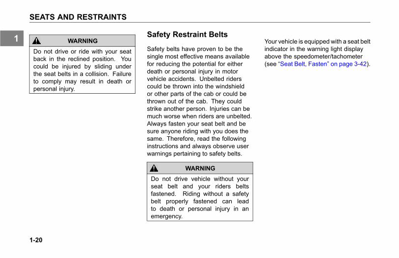
Safety belts have proven to be thesingle most effective means availablefor reducing the potential for eitherdeath or personal injury in motorvehicle accidents. Unbelted riderscould be thrown into the windshieldor other parts of the cab or could bethrown out of the cab. They couldstrike another person. Injuries can bemuch worse when riders are unbelted.Always fasten your seat belt and besure anyone riding with you does thesame. Therefore, read the followinginstructions and always observe userwarnings pertaining to safety belts.
WARNING
Do not drive vehicle without yourseat belt and your riders beltsfastened. Riding without a safetybelt properly fastened can leadto death or personal injury in anemergency.
Your vehicle is equippedwith a seat beltindicator in the warning light displayabove the speedometer/tachometer(see “Seat Belt, Fasten” on page 3-42).
1-20
1

SEATS AND RESTRAINTS
Lap/Shoulder Belt
The combination lap-shoulder belt isequipped with a locking mechanism.The system adjusts automatically to aperson's size and movements as longas the pull on the belt is slow.
Hard braking or a collision locks thebelt. The belt will also lock whendriving up or down a steep hill or in asharp curve.
To fasten the belt:1. Grasp the belt tongue.
2. Pull belt in a continuous slowmotion across your chest and lap.
3. Insert belt tongue into buckle oninboard side of seat.
4. Push down until the tongue issecurely locked with an audibleclick.
5. Pull belt to check for properfastening and adjustment, asfollows:
• Pull shoulder section to make surebelt fits snugly across the chestand pelvis.
• There should be less than 1 inch(25 mm) gap between the bodyand the belt.
• The shoulder belt must bepositioned over the shoulder, itmust never rest against the neckor be worn under the arm.
• Make sure any slack is wound upon the retractor and that the beltis not twisted.
To unfasten the belt:1. Push in the release button on the
buckle.
2. The belt will spring out of thebuckle.
If the belt is locked, lean the body backto remove any tension in the belt. Afterreleasing the belt, allow the belt toretract completely by guiding the belttongue until the belt comes to a stop.
1-21
1

SEATS AND RESTRAINTS
Safety Restraint Belts
Lap Belt Shoulder Belt
Correct Incorrect (too high on hips) Correct (over arm) Incorrect (under arm) Incorrect (twisted)
WARNING
Proper seat belt adjustment and useis important to maximize occupantsafety. Failure to wear or adjustthe safety belt properly may result indeath or personal injury.
Tether Belts
This vehicle may have an externaltether belt installed with a seat, insteadof the internal tethering device. Tetherbelts are designed to restrain the seatin the event of a sudden stop or anaccident.
Internal tether belts do not requireadjustment.
1-22
1
SEATS AND RESTRAINTS
WARNING
Do not remove, modify, or replacethe tether belt systemwith a differenttether system. A failed or missingtether belt could allow the seat baseto fully extend in the event of anaccident. Failure to comply mayresult in death or personal injury.
WARNING
Failure to adjust tether belts properlycan cause excessive movementof the seat in an accident. Tetherbelts should be adjusted so thatthey are taut when the seat is in itsmost upward and forward position.Failure to comply may result in deathor personal injury.
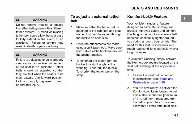
To adjust an external tetherbelt• Make sure that the tether belt is
attached to the cab floor and seatframe. It should be routed throughthe buckle on each side.
• Often the attachments are madeusing a split-type hook. Make sureboth halves of the hook are aroundthe anchor bracket.
• To lengthen the tether, turn thebuckle to a right angle to thewebbing. Then pull the buckle.To shorten the tether, pull on thestrap.
Komfort-Lok® Feature
Your vehicle includes a featuredesigned to eliminate cinching andprovide improved safety and comfort.Cinching is the condition where a beltbecomes continually tighter aroundyou during a rough, bouncy ride. Theneed for this feature increases withrough road conditions, particularly overlong distances.
To eliminate cinching, simply activatethe Komfort-Lok feature located on theseat belt webbing at the appropriatetime.
1. Fasten the seat belt accordingto instructions, See Seats andRestraints on page 1-19.
2. You are now ready to activate theKomfort-Lok. Lean forward to pulla little slack in the belt [maximumof 1 in. (25 mm), measured fromthe belt to your chest]. Be sure toallow only a small amount of slack.
1-23
1
SEATS AND RESTRAINTS
See Safety Restraint Belt Warningon page 1-22
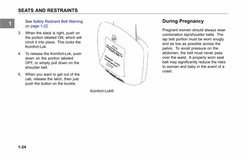
3. When the slack is right, push onthe portion labeled ON, which willcinch it into place. This locks theKomfort-Lok.
4. To release the Komfort-Lok, pushdown on the portion labeledOFF, or simply pull down on theshoulder belt.
5. When you want to get out of thecab, release the latch, then justpush the button on the buckle.
Komfort-Lok®
During Pregnancy
Pregnant women should always wearcombination lap/shoulder belts. Thelap belt portion must be worn snuglyand as low as possible across thepelvis. To avoid pressure on theabdomen, the belt must never passover the waist. A properly worn seatbelt may significantly reduce the risksto woman and baby in the event of acrash.
1-24
1

SEATS AND RESTRAINTS
Pregnant Woman with Belt ProperlyWorn
Belt Damage and Repair
Damaged belts in the cab mustbe replaced. Belts that have beenstretched, cut, or worn out may notprotect you in an accident.
If any seat belt is not working properly,see an Authorized Service Center forrepair or replacement.
For further information on seat beltsand seat belt maintenance, see SafetyRestraint System - Inspection on page5-66.
Sleeper Bunks andRestraints
For cabs equipped with a sleeper, besure to use the restraint devices whenthe vehicle is in motion. Your vehicle
1-25
1

SEATS AND RESTRAINTS
may have belts and/or a net restraintsystem which are over the bunk orcover the opening.
If your vehicle has an upper and lowerbunk, the upper bunk can be folded upout of the way to provide you with moreroom in the sleeper. Fold the upperbunk up and insert the metal end of thebunk retaining belts into the buckles.
WARNING
Be sure the restraint system isused when anyone is occupying thesleeper while the vehicle is moving.In an accident, an unrestrainedperson lying in a sleeper bunk couldbe seriously injured. He or shecould be thrown from the bunk.Failure to comply may result indeath, personal injury, equipment orproperty damage.
Lower:
WARNING
Always keep the lower bunk in itsdown position while the vehicle ismoving. If left in the up position,stored items could become looseduring an accident and strike you,causing death or personal injury.
Before you move the vehicle, check tobe sure the lower bunk is in the downposition.
Upper:
WARNING
Be sure the latch that holds theupper bunk in the folded positionis working properly so the bunk willnot fall down. Pull on the bunk tobe sure it is latched securely. Ifthe bunk falls, you could be injured.Failure to comply may result indeath, personal injury, equipment orproperty damage.
Per FMCSR 392.60 - UnauthorizedPersons Not to be Transported.Federal law prohibits the transportationof persons in commercial vehiclesunless they are specifically authorizedin writing by the motor carrier. Seethe cited FMCSR for a completedescription of the regulation andexemptions.
1-26
1

SEATS AND RESTRAINTS
WARNING
Any loose items on the upper orlower bunk should be moved to asecured place before driving thevehicle. Failure to complymay resultin death, personal injury, equipmentor property damage.
Upper Rear Sleeper Storage
Your vehicle may be equipped with anupper storage shelf that extends overthe lower bunk and across the rearof the sleeper. The following warningapplies:
WARNING
Overhead compartments are notintended for items exceeding theirdesigned weight limits. Exceedingthe weight limits may cause the shelfto collapse and or items may fall outin a sudden stop which may lead todeath or personal injury.
Compartments in the cab and sleeperare provided for storage of necessaryitems used during operation. Thestorage areas above the door aredesigned to hold a combined totalnot exceeding 14 lbs (6 kg) percompartment and the other overheadcompartments (including those in
the optional sleeper) should hold acombined total not exceeding 5 lbs(2.2 kg) per compartment.
1-27
1

SEATS AND RESTRAINTS
Safety Restraint Tips• Do not wear a belt over rigid or
breakable objects in or on yourclothing, such as eye glasses,pens, keys, etc., as these maycause injury in an accident.
• Any authorized person sleepingin your vehicle while it is movingshould use the bunk restraint.
• Any authorized person sitting inthe sleeper area on the sofa bed(if equipped) while it is movingshould wear a seat belt.
• A responsible operator sees to itthat everyone in the vehicle ridesor sleeps safely. The operatoris responsible to inform anypassengers or co-drivers how toproperly use the seat belts andbunk restraint in the vehicle.
• Do not strap in more than oneperson with each belt.
• Keep seat belt and bunk restraintbuckles free of any obstructionthat may prevent secure locking.
• Damaged or worn belts in the cabor sleeper, subjected to excessivestretch forces from normal wear,must be replaced. They maynot protect you if you have anaccident.
• Any belts or restraints that havebeen subjected to an accidentshould be inspected for any loose(attaching) hardware or damagedbuckles.
• If belts show damage to any partof assembly, such as webbing,bindings, buckles or retractors,they must be replaced.
• Do not allow safety belts (seator bunk) to become damaged bygetting caught in door, bunk orseat hardware, or rubbing againstsharp objects.
• All belts must be kept clean or theretractors may not work properly.
• Never bleach or dye seat or bunkrestraint belts: chemicals canweaken them. Do, however, keepthem clean by following the carelabel on the belts. Let them drycompletely before allowing themto retract or be stowed away.
• Make sure the seat belts andbunk restraint of the unoccupiedpassenger seat or bunk is fullywound up on its retractor oris stowed, so that the belt orrestraint tongue is in its properlystowed position. This reduces thepossibility of the tongue becominga striking object in case of asudden stop.
• Do not modify or disassemble theseat belts or bunk restraint in yourvehicle. They will not be available
1-28
1

SEATS AND RESTRAINTS
to keep you and your passengerssafe.
• If any seat belt or bunk restraintis not working properly, see anauthorized dealer for repair orreplacement.
1-29
1

START-UP
START-UP
Introduction
The following section covers start-upprocedures for getting your vehicleready for the road.
Safe Vehicle Operation
For your safety, as well as thosearound you, be a responsible driver:
• If you drink alcohol, do not drive.
• Do not drive if you are tired, ill, orunder emotional stress.
Safe driving is only possible with theproper concentration on the drivingtask. Keep distraction to a minimum toimprove your concentration. Examplesof distractions may include radiocontrols, GPS navigation controls,cellular telephone calls, cellular textmessages, reading or reaching forsomething on the floor. Minimizingyour distractions will improve safedriving and will help avoid an accidentinvolving death or personal injury.
Be aware of local regulations that mayprohibit the use of cellular telephoneswhile driving. In addition to being anunsafe practice, it may be against local
or federal ordinances to use cellulardevices while operating the vehicle.
Much has gone into the manufacturingof your vehicle including advancedengineering techniques, rigid qualitycontrol, and demanding inspections.These manufacturing processes willbe enhanced by you, the safe driver,who observes the following:
• Knows and understands how tooperate the vehicle and all itscontrols.
• Maintains the vehicle properly.
• Uses driving skills wisely.
For more information, refer toDepartment of TransportationRegulation 392.7, which states thatinterstate commercial motor vehiclesare not to be driven unless the driver issure that certain parts and accessoriesare in working order.
1-30
1

START-UP
WARNING
The use of alcohol, drugs, andcertain medications will seriouslyimpair perception, reactions, anddriving ability. These circumstancescan substantially increase the riskof an accident. Failure to complymay result in death, personal injury,equipment or property damage.
Do not drink alcohol and drive. Yourreflexes, perceptions, and judgmentcan be affected by even a smallamount of alcohol. You could have aserious or even fatal accident, if youdrive after drinking. Please do notdrink and drive or ride with a driverwho has been drinking.
WARNING
Do not text and drive. Your reactiontime, perceptions and judgment canbe affected while texting or usingany other form of mobile messagingwhile driving. Failure to complymay result in death, personal injury,equipment or property damage.
Vehicle Loading
Compare your vehicle's load capacitywith the total load you are carrying. Ifadjustments need to be made, makethem, do not drive an overloadedvehicle. If you are overloaded or yourload has shifted, your vehicle may beunsafe to drive.
WARNING
Do not exceed the specified loadrating. Overloading can result in lossof vehicle control, either by causingcomponent failures or by affectingvehicle handling. Exceeding loadratings can also shorten the servicelife of the vehicle. Failure to complymay result in death or personalinjury.
The gross vehicle weight rating(GVWR), or the maximum frontand rear gross axle weight ratings(GAWRs) are determined by the
1-31
1

START-UP
components installed from the factoryon to the vehicle and their designedspecifications. (Axle weight ratings arelisted on the driver's door edge.)
The following are some definitions ofweight you should know:
GVWR: is the Gross Vehicle WeightRating. This is the MAXIMUMWEIGHT your vehicle is allowed tocarry, including the weight of the emptyvehicle, loading platform, occupants,fuel, and any load. Never exceed theGVWR of your vehicle.
GCW: is the actual combined weight,or Gross Combination Weight (GCW),of your vehicle and its load: vehicle,plus trailer(s), plus cargo.
GAWR: is the Gross Axle WeightRating. This is the total weight thatone axle is designed to transmit to theground. You will find this number listedon the driver's door edge.
Load Distribution: be sure any loadyou carry is distributed so that no axlehas to support more than its GAWR.
WARNING
An unevenly distributed load or aload too heavy over one axle canaffect the braking and handling ofyour vehicle, which could result inan accident. Even if your load isunder the legal limits, be sure it isdistributed evenly. Failure to complymay result in death, personal injury,equipment or property damage.
1-32
1

START-UP
Emergency Equipment
It is good practice to carry anemergency equipment kit in yourvehicle. One day, if you have aroadside emergency, you will be gladthe following items are with you:
• window scraper
• snow brush
• container or bag of sand or salt
• emergency light
• warning triangles
• small shovel
• first aid kit
• fire extinguisher
• vehicle recovery hitches (seeVehicle Recovery Guidelines onpage 2-12 for details).
Driver's Check List
To keep your vehicle in top shape andmaintain a high level of safety for you,your passengers, and your load, makea thorough inspection every day beforeyou drive. You will save maintenancetime later, and the safety checkscould help prevent a serious accident.Please remember, too, that FederalMotor Carrier Safety Regulation 392.7requires a pre-trip inspection and sodo commercial trucking companies.
You are not expected to become aprofessional mechanic. The purposeof your inspections is to find anythingthat might interfere with the safe andefficient transportation of yourself, anypassengers, and your load. If you dofind something wrong and cannot fix ityourself, have an authorized dealer orqualified mechanic repair your vehicleright away.
The following operations are to beperformed by the driver. Performingthese checks and following themaintenance procedures in thismanual will help keep your vehiclerunning properly.
1-33
1

START-UP
Approaching Your Vehicle• Check the overall appearance and
condition. Are windows, mirrors,and lights clean and unobstructed?
• Check beneath the vehicle. Arethere signs of fuel, oil, or waterleaks?
• Check for damaged, loose, ormissing parts. Are there partsshowing signs of excessive wearor lack of lubrication? Have aqualified mechanic examine anyquestionable items and repairthem without delay.
• Check your load. Is it securedproperly?
Daily Checks
Engine Compartment Checks- Daily1. Engine Fluid Levels - add more if
necessary.
a. Engine oil
b. Coolant (check while engineis cold)
c. Power steering fluid level
2. Engine Belt - check tension andcondition of belts.
a. See Accessory Drive Beltson page 5-95 for furtherinformation on checking belttension.
NOTEDeflection should be one beltthickness for each foot distancebetween the pulley centers.
b. Replace belts that are crackedtorn or broken.
3. Fuel Filter/Water SeparatorDraining - check and drain.Depending on the fuel storagefacility, more frequent drainingmay be required.
4. Windshield washer reservoir fluidlevel - fill if necessary.
5. Battery Cables - check thecondition of the battery andalternator cables for signs ofchafing or rubbing. Make surethat all clamps (straps) holding thecables are present and in goodworking order.
6. Hood closed before entering cab.Is it latched properly?
7. Check brake lines and hoses.
8. Check the steering components(pitman arm, draglink, powersteering hoses, etc.).
1-34
1

START-UP
9. Check clutch hydraulic fluid.
Chassis and Cab Checks -Daily
Before entering the cab and operatingthe vehicle, check the followingequipment for proper maintenance:
1. Lights - are any exterior lightscracked or damaged?Perform an exterior light test usingthe dash mounted switch next tothe steering wheel. See ExteriorLighting Self-Test on page 3-63.
2. Windows and Mirrors - are theyclean and adjusted properly?
3. Tires and Wheels - are theyinflated properly? Are all wheelcap nuts in place and torquedproperly - tighten if necessary.Check front wheel bearing oillevels. Inspect all tires and wheelsfor damage - correct if found.
4. Suspension - check for loose ormissing fasteners. Check damageto springs or other suspensionparts such as cracks, gouges,distortions, bulges or chafing.
5. Brake Components - check lines,linkages, chambers, parking andservice brake operation.
6. Air System - are there leaks?Air Tanks - drain water from all airtanks. Make sure the drain cocksare closed. This procedure is alsorequired for air suspension tanksequipped with automatic drainvalves.For further details See Using theBrake System on page 4-22.
7. Steps and Handholds - checkfor worn surfaces and loose ormissing fasteners (which includesany fuel tank steps).
8. Fluid Tanks (Fuel, DEF, etc.) -check underneath the vehicle for
signs of fluid leaks. If any arefound, correct before operating thevehicle.
9. Fuel Tank Hardware - are thetanks fill caps secure? Are thetank straps tight? Is the strapwebbing in place?
WARNING
Diesel fuel in the presence of anignition source (such as a cigarette)could cause an explosion. Donot remove a fuel tank cap nearan open flame. Use only the fueland/or additives recommendedfor your engine. A mixture ofgasoline or alcohol with diesel fuelincreases this risk of explosion.Failure to comply may result indeath, personal injury, equipment orproperty damage. See Refueling onpage 4-63, for more information.
10. Trailer Connections - are theysecure and the lines clear? If
1-35
1

START-UP
they are not being used, are theystored properly?
a. Is the trailer spare wheelsecure and inflated?
b. Is the landing gear up and thehandle secured?
11. Check the fifth wheel. Is thekingpin locked?
a. Is the sliding fifth wheellocked?
Cab Interior - Daily1. Seat - adjust the seat for easy
reach of controls and visibility.
2. Seat Belts - fasten and adjustsafety restraint belts (which mayinclude restraints in the sleeper).
3. Steering Column - adjust for easyreach and visibility.
4. Mirrors - check and readjustmirrors if necessary.
5. Lights - turn ignition key to the ONposition and check for warninglights and buzzer. Check operationof turn signals and emergencylights.
6. Instruments - check allinstruments.
7. Windshield - check operation ofwindshield wipers and washers.
8. Horn - check operation of horn.
9. Fuel - check fuel. Is there enoughfuel?
10. Diesel Exhaust Fluid (DEF) -check level. Is there enough fluid?
11. Sleeper air conditioning air filter -check the condition of the sleeperair conditioning air filter. Keepthe sleeper floor area behindthe passenger front seat clear ofdebris and pet hair. The sleeperair conditioner draws air from thisarea and excessive dirt or pet hair
may shorten the service life of thesleeper air conditioning air filter.
The above items should be checkeddaily, as a minimum. They are inaddition to, not in place of, FederalMotor Carrier Safety Regulations.These regulations may be purchasedby writing to:
Superintendent of Documents
U.S. Government Printing Office
Washington, DC 20402
1-36
1

START-UP
Weekly Operations1. Battery - check battery and
terminals.
2. Wheel Cap Nuts - are they allin place and torqued properly -tighten if necessary. See WheelCap Nut Torque on page 5-140.
3. Other Controls and Wiring - checkfor condition and adjustment
4. Steering Components - checkpitman arm, draglink, and powersteering hoses, etc., for loose,broken, or missing parts.
5. HVAC Fresh Air Filter - check forcondition and cleanliness.
6. Other Engine CompartmentChecks
a. Check condition and fasteningof engine belt, hoses, clamps,and radiator.
b. Check the air cleaner, muffler,and exhaust pipes. Are theytight and secure?
c. For vocational vehicleswith optional engine airpre-cleaner, check the purgevalve at the bottom of the hoodmounted engine air precleanerfor any obstructions. Makesure the purge valve will openand close as needed to purgedirt and water from the engineintake air.
d. Automatic transmission fluid(when applicable) - Checklevel, after the engine haswarmed up to operatingtemperature.
1-37
1


EMERGENCY
WHAT TO DO IF...You Need Roadside Assistance. . . . . . . . . . 2-3Low Air Alarm Turns On . . . . . . . . . . . . . 2-3Stop Engine Lamp Turns On . . . . . . . . . . . 2-4Engine Oil Pressure Lamp Turns On. . . . . . . . 2-4Engine is Overheating . . . . . . . . . . . . . . 2-5Fuse or Relay Blows . . . . . . . . . . . . . . 2-6
JUMP STARTING VEHICLESIntroduction . . . . . . . . . . . . . . . . . . 2-8
VEHICLE RECOVERY AND SPRING BRAKESVehicle Recovery Guidelines . . . . . . . . . . 2-12Returning Vehicle to Service . . . . . . . . . . 2-20Spring Brakes—Manual Release . . . . . . . . 2-20Sand, Mud, Snow and Ice . . . . . . . . . . . 2-22Towing the Vehicle . . . . . . . . . . . . . . 2-23
2-1
2


WHAT TO DO IF...
WHAT TO DO IF...
You Need RoadsideAssistance
Call toll-FREE 1-800-KW-ASSIST(1-800-592-7747) to talk to someoneat the PACCAR Customer Center.
• Open 24-7-365 days a year
• They can help you get roadsideassistance.
• They have a custom mappingsystem which locates KenworthDealers and Independent ServiceProviders (ISPs) near you and liststypes of services offered, hours ofoperation and contact information.
• They can assist with jump andpull starts, tires, trailers, fines and
permits, chains, towing, hazardousclean-up, out of fuel (roadside),mechanical repairs and preventivemaintenance services.
• They have bilingual agents andaccess to a translation serviceto ensure quality assistancefor customers who speak anylanguage.
• They can’t answer your warrantyquestions but can get you incontact with a Kenworth dealerwho can.
• The PACCAR Customer Centerservice is FREE even if you don’tdrive a Kenworth.
Low Air Alarm Turns On
1. Slow down carefully.
2. Move a safe distance off the roadand stop.
3. Place the transmission inneutral (park with automatictransmissions, if equipped) andset the parking brake. (Referto Parking Brake Valve onpage 4-35 and Operating theTransmission on page 4-19, fortransmission shifting and parkingbrake information.)
4. Turn OFF the engine.
5. Turn ON the emergency flasherand use other warning devices toalert other motorists.
2-3
2

WHAT TO DO IF...
WARNING
If the air pressure falls below 60psi (414 kPa) the spring brakesmay stop the vehicle abruptly, whichcould cause an accident resulting indeath or personal injury. Observethe red warning lamps on thegauges. If one comes on, do notcontinue to drive the vehicle untilit has been properly repaired orserviced.
If the light and alarm do not turn off atstartup, do not try to drive the vehicleuntil the problem is found and fixed.(Refer to Using the Brake System onpage 4-22, for more brake information.)
Stop Engine Lamp Turns OnStop Engine Lamp - If theStop Engine warning lampilluminates, it means youhave a serious engine systemproblem.
WARNING
This should be considered anemergency. You should stop thevehicle as safely as possible andturn OFF the ignition. The vehiclemust be serviced and the problemcorrected before driving again.Failure to do so may cause severeengine or DPF damage, or cause anaccident which may result in deathor personal injury.
Engine Oil Pressure LampTurns On
Engine Oil Pressure Lamp- If the oil pressure suddenlydrops, or the audible alarm andengine oil pressure warninglight come on while driving, dothe following:
1. Slow down carefully.
2. Move a safe distance off the roadand stop.
3. Place the transmission in parkand set the parking brake.(See Parking Brake Valve onpage 4-35 and Operating theTransmission on page 4-19, fortransmission shifting and parkingbrake information.)
4. Turn OFF the engine.
5. Turn ON the emergency flasherand use other warning devices toalert other motorists.
2-4
2

WHAT TO DO IF...
6. Wait a few minutes to allow oil todrain into the engine oil pan, andthen check the oil level. (See OilLevel Check on page 5-92, fordetails on checking oil level.)
7. Add oil if necessary. If the problempersists, contact an authorizeddealer as soon as possible.
CAUTION
Continuing to operate your vehiclewith insufficient oil pressure maycause severe engine damage orcause an accident which may resultin equipment or property damage.
It is important to maintain oil pressurewithin acceptable limits. If oil pressuredrops below the minimum psi (kPa) aRed Warning Lamp on the oil pressuregauge will illuminate and the StopEngine Lamp will come ON.
Engine is Overheating
The cooling system may overheat ifthe coolant level is below normal or ifthere is sudden loss of coolant, suchas a split hose. The system may alsotemporarily overheat during severeoperating conditions such as:
• Climbing a long hill on a hot day
• Stopping after high-speed driving
If either one of the above occurs, DONOT TURN OFF THE ENGINE unless:a) the Low Water warning deviceindicates a loss of coolant, b) the RedWarning lamp (on the gauge) andCheck Engine lamp comes ON, c) theBuzzer sounds showing an overheatcondition, or d) if you have any otherreason to suspect the engine may beoverheating - follow these steps.
1. Reduce engine speed andstop. When stopped, place thetransmission in Neutral and set the
parking brake. (See Parking BrakeValve on page 4-35 and Puttingthe Vehicle in Motion on page4-16, for transmission shifting andparking brake information.) Keepthe engine running.
2. Check to ensure the Oil PressureGauge reads normal. (See EngineOil Pressure Gauge on page 3-11,for further information.)
3. Make sure the engine fan isturning by switching the EngineFan Switch from AUTO to MAN(Manual).
4. Increase the engine speed toabout one-half of full operatingspeed, or 1,100 to 1,200 rpm,maximum.
5. Return the engine speed to normalidle after 2 or 3 minutes.
6. Monitor the engine temperature.After the temperature returns tonormal, allow the engine to idle
2-5
2

WHAT TO DO IF...
3 to 5 minutes before shutting itoff. This allows the engine to coolgradually and uniformly.
7. If overheating came fromsevere operating conditions, thetemperature should have cooledby this time. If it has not, stopthe engine and let it cool beforechecking to see if the coolant islow.
For further information on enginetemperature and operating enginesproperly, see the Engine Operationand Maintenance Manual and Starting& Operating the Vehicle on page 4-5.Check the coolant level after eachtrip when the engine has cooled.The coolant level should be visiblewithin the surge tank—add coolant ifnecessary. See Topping Off in EngineCooling System on page 5-71, forinstructions on checking and filling thecoolant expansion tank.
WARNING
To reduce the chance of death,personal injury and/or vehicledamage from overheated engines,which can result in a fire, neverleave the engine idling without analert driver present. If the engineshould overheat, as indicated bythe engine coolant temperaturelight, immediate action is requiredto correct the condition. Continuedunattended operation of the engine,even for a short time, may result inserious engine damage or a fire.
WARNING
Do not remove the radiator fill capwhile the engine is hot. Scaldingsteam and fluid under pressure mayescape. You could be badly burned.Failure to comply may result in deathor personal injury.
Fuse or Relay Blows
Fuses are located behind the driversside kick panel, below the ignitionswitch, and accessible by a door panel.See Power Distribution Box on page5-82.
The vehicle main power relays arelocated in the engine compartment.See Power Distribution Center (PDC)on page 5-79.
WARNING
Do not replace a fuse with a fuse of ahigher rating. Doing somay damagethe electrical system and cause afire. Failure to comply may result indeath, personal injury, equipment orproperty damage.
2-6
2

WHAT TO DO IF...
CAUTION
Before replacing a fuse, turn OFF alllights and accessories and removethe ignition key to avoid damagingthe electrical system.
CAUTION
Never patch fuses with tin foil orwire. This may cause seriousdamage elsewhere in the electricalcircuit, and it may cause a fire.
CAUTION
If a circuit keeps blowing fuses,have the electrical system inspectedfor a short circuit or overload byan authorized dealer as soon aspossible. Failure to do so couldcause serious damage to theelectrical system and/or vehicle.
Fuse Inspection andReplacement
All the electrical circuits have fusesto protect them from a short circuit oroverload. If something electrical onyour chassis stops working, the firstthing you should check for is a blownfuse.
1. TurnOFF all lights and accessoriesand remove the ignition key toavoid damaging the electricalsystem.
2. Determine from the chart on thefuse panel which fuse controls thatcomponent.
3. Remove that fuse and see if it isblown.
1 Blown
If it is blown, replace it with a fuse ofthe same rating.
If a fuse of the same rating is notavailable, a fuse of a lower rating maybe temporarily substituted. You canalso use a fuse from a circuit you cando temporarily without (for example anaccessory circuit or radio).
CAUTION
When replacing a failed circuitbreaker, always use an approvedcircuit breaker with a current ratingequal to or less than the circuitbreaker being replaced. Only usethe approved Type II modified resetcircuit breakers. NEVER use aType I (automatic reset) or Type III(manual reset) circuit breaker. Afuse with a current rating equal to orless than the circuit breaker beingreplaced can also be used.
2-7
2
JUMP STARTING VEHICLES
JUMP STARTINGVEHICLES
Introduction
Jump starting a vehicle is not arecommended practice due to thevarious battery installations andelectrical options.
However, if your battery is discharged(dead), you may be able to start itby using energy from a good batteryin another vehicle. This is termedjump starting. Be sure to follow theprecautions and instructions below.
WARNING
Batteries contain acid that canburn and gasses that can explode.Ignoring safety procedures mayresult in death, personal injury,equipment or property damage.
WARNING
Never jump start a battery nearfire, flames, or electrical sparks.Batteries generate explosive gasesthat could explode. Keep sparks,flame, and lighted cigarettes awayfrom batteries. Failure to complymay result in death, personal injury,equipment or property damage.
WARNING
Never remove or tamper withbattery caps. Ignoring this couldallow battery acid to contact eyes,skin, fabrics, or painted surfaces.Failure to comply may result indeath, personal injury, equipment orproperty damage.
Be careful that metal tools (or anymetal in contact with the positiveterminal) do not contact the positivebattery terminal and any other metal onthe vehicle at the same time. Remove
metal jewelry and avoid leaning overthe battery.
2-8
2

JUMP STARTING VEHICLES
To Jump Start Your Vehicle
WARNING
When jump starting using a batterybooster, it is best to jump startwith an equivalently poweredvehicle. Verify that the boosterbattery has the same volt andCCA specifications as the deadbattery before attempting to jumpstart. Failure to comply maycause an explosion resulting indeath, personal injury, equipment orproperty damage.
CAUTIONApplying a higher voltage boosterbattery may cause expensivedamage to sensitive electroniccomponents, such as relays,Electronic Control units orelectronics in general. Failure tocomply may result in equipmentdamage.
CAUTION
Improper hook-up of jumper cablesor not following these procedurescan damage the alternator or causeserious damage to both vehicles.
WARNING
Heed all warnings and instructionsof the jumper cable manufacturer.Failure to comply may result indeath, personal injury, equipment orproperty damage.
Preparing the vehicles:1. Remove any personal jewelry
that may come in contact with thebattery terminals.
2. Select a jumper cable that is longenough to attach to both vehiclesin a way that ensures neithervehicle touches each other.
3. Position the two vehicles together,but do not allow them to touch.
4. Turn OFF all lights, heater, radio,and any other accessory on bothvehicles.
5. Set the parking brakes: pull outthe Yellow button located on thedash.
6. Shift the transmission into parkposition or neutral for manualtransmissions. (See Operatingthe Transmission on page 4-19and Parking Brake Valve on page4-35, for transmission shifting andparking brake information.)
2-9
2

JUMP STARTING VEHICLES
7. If either vehicle is equipped withbattery disconnects ensure theyare in the "OFF" position prior toconnecting the two vehicles.
Connect the batteries:1. Attach one end of a jumper cable
to the positive (+) terminal of thedischarged (dead) battery. Thiswill have a large red + or P on thebattery case, post, or clamp.
2. Attach the other end of the samecable to the positive (+) terminalof the good (booster) battery.
3. Attach the remaining jumper cableFIRST to the negative (-) terminal(black or N) of the good battery.
4. Attach the other end of thenegative cable to a bare metal partnot bolted to the engine block.
NOTEAlways connect positive (+) topositive (+) and negative (-) tonegative (-).
5. If either vehicle is equipped withbattery disconnects, ensure thatthey are in the "ON" position.
6. Start the vehicle that has thegood battery first. Let it run for 5minutes.
7. Start the vehicle that has thedischarged (dead) battery.
If the engine fails to start, do notcontinue to crank the starter butcontact the nearest authorized dealer.
2-10
2

JUMP STARTING VEHICLES
Remove jumper cables:
WARNING
When disconnecting jumper cables,make sure they do not get caughtin any moving parts in the enginecompartment. Failure to complymay result in death, personal injury,equipment or property damage.
Reverse the above procedure exactlywhen removing the jumper cables.With engine running, disconnectjumper cables from both vehicles inthe exact reverse order, making sureto first remove the negative cable fromthe vehicle with the discharged battery.
2-11
2

VEHICLE RECOVERY AND SPRING BRAKES
VEHICLE RECOVERYAND SPRING BRAKES
Vehicle Recovery Guidelines
Your vehicle is equipped withremovable Recovery Hitches,designed for short distance recoverypurposes only. Use only the providedhitches, according the followinginstructions. When using thisconnection, do not transport yourvehicle over long distances. (If yourvehicle does not have the properhitches, contact your dealer.)
All lubricating and clutch applicationoil pressure is provided by anengine-driven pump, which will notwork when the engine is stopped.You could seriously damage yourvehicle by towing it with the drivelineconnected and the drive wheels onthe ground. Worse, when vehicles aretowed, either by wrecker or piggyback,
the lubricant in the top front of thedrive axle will drain to the rear. Thiswill leave the top components dry. Theresulting friction may damage them.Always remove the main drive axleshafts before towing your vehicle.
CAUTION
Remove the drive axle shafts or liftthe driving wheels off the groundbefore towing the vehicle. Towingthe vehicle with either the wheels onthe ground or the axle shafts in theaxles will cause damage to the axlegears.
CAUTION
If your vehicle has aMeritor axle witha driver-controlled main differentiallock, install the caging bolt beforeremoving the axles for towing, seeDriver Controlled Main DifferentialLock on page 2-16. Installing thecaging bolt prevents damage bylocking internal axle components inposition.
CAUTION
Connect only to the RecoveryHitches, see Vehicle RecoveryGuidelines on page 2-12.Connections to other structuralparts could damage the vehicle. Donot attach to bumpers or brackets.Use only equipment designed forthis purpose. Failure to comply mayresult in equipment damage.
2-12
2

VEHICLE RECOVERY AND SPRING BRAKES
1 Recovery Hitch Sockets
Recovery Procedure1. Review and understand all the
cautions and warnings of thissection, see Vehicle RecoveryGuidelines on page 2-12.
2. Install the recovery hitches, seeRecovery Hitch Installation onpage 2-15.
3. Disconnect the drive axle shaftsand cover the open hubs. Thisis necessary because if thetransmission is driven by thedriveshaft (rear wheels on theground), no lubricant will reachthe gears and bearings, causingdamage to the transmission.
4. Install the recovery rigging using asafety chain system, see RecoveryRigging on page 2-19.
5. Make sure the recovered vehicle'sparking brakes are released.
6. If you desire to use the recoveredvehicle’s brakes, ensure that
the vehicle’s air system isconnected to that of the recoveryvehicle. Ensure that any air linethat has been removed from adriver-controlled main differentiallock is firmly capped to preventloss of air pressure from therecovery vehicle if it is supplyingair pressure.If you don’t desire to use therecovered vehicle’s brakes,ensure that you cage the springbrakes before attempting to movethe vehicle, see Driver ControlledMain Differential Lock on page2-16.
2-13
2

VEHICLE RECOVERY AND SPRING BRAKES
WARNING
Before towing a vehicle, test yourair brakes to ensure that you haveproperly connected and inspectedthe recovery vehicle’s brake system.Failure to do so could lead to a lossof vehicle control which may resultin an accident involving death orpersonal injury.
7. Follow state/provincial and locallaws that apply to vehicles in tow.
8. Do not tow vehicles at speeds inexcess of 55 mph (90 km/h).
For additional information concerningheavy duty truck recovery, refer to thefollowing Technology & MaintenanceCouncil (TMC) literature.
• Recommended Practice #602–A— “Front Towing Devices ForTrucks and Tractors.”
• Recommended Practice #602–B— “Recovery Attachment PointsFor Trucks, Tractors, andCombination Vehicles."
• Recommended Practice #626— “Heavy Duty Truck TowingProcedures.”
Copies of these can be obtained fromthe following address:
Technology & Maintenance Council950 N. Glebe Road(703) 838-1763Arlington, VA 22203Email: [email protected]://tmc.truckline.com
Recovery Hitch Connection
Specially designed hitches arerequired to recover your vehicle. Therecovery hitches attach to the frame,see Recovery Hitch Assembly on page2-15.
Two hitch assemblies, made up of thefollowing parts, are recommended forthe proper recovery of your vehicle:see Recovery Hitch Assembly on page2-15.
WARNING
Do not use parts from other trucksor materials from other sourcesto repair a hitch or to replace amissing hitch. The parts providedfor recovery are made of highstrength steel specifically designedfor vehicle recovery. Failure to usethe correct factory equipment mayresult in an accident involving deathor personal injury.
2-14
2

VEHICLE RECOVERY AND SPRING BRAKES
If your vehicle is not equipped withthe proper recovery hitch assembly,contact an authorized dealer to obtainthe proper equipment.
Recovery Hitch Assembly
1 Tow Pin2 Tow Hitch3 Square Hitch Socket4 Lock Pin5 Lock Tab
Recovery Hitch Installation
Use the following procedure to installthe Vehicle Recovery Hitches. SeeRecovery Hitch Assembly illustrationfor part identification.
1. Check square sockets behindlower bumper for obstructions,clear if necessary.
2. With lock pins removed, inserthitches through bumper and intothe square hitch socket.
3. Align the hole in the tow hitch withthe square hitch socket hole.
4. Insert the lock pin into the squarehitch socket hole and throughthe hole in the tow hitch until thelock tab is within the square hitchsocket.
5. Rotate the lock pin 90 degrees tosecure the pin in place.
6. Remove the hitches and store allparts after recovering the vehicle.
2-15
2

VEHICLE RECOVERY AND SPRING BRAKES
Driver Controlled MainDifferential
Follow these steps to lock adriver-controlled main differential.
WARNING
An open air line on the recoveredvehicle will cause a leak in the airsystem of the recovery vehicle ifboth vehicles’ brake systems areconnected. This could cause aloss of system air, which can causethe service brakes not to function,resulting in the sudden applicationof the spring brakes causing wheellock-up, loss of control, or overtakeby following vehicles. You couldbe in an accident involving deathor personal injury. Ensure that anyair line that has been removed froma driver-controlled main differentiallock is firmly capped to prevent lossof air pressure from the recoveryvehicle if it is supplying air pressure.
Driver Controlled Main DifferentialLock
1 Air Line (remove to installCaging Bolt)
2 Caging Bolt (in storagelocation)
1. Lift driving wheels off the groundor remove the driveline and axleshafts before towing the vehicle.
CAUTION
Failure to lift the driving wheels offthe ground or remove the drivelineand axle shafts before towing thevehicle could seriously damage yourvehicle. All lubricating and clutchapplication oil pressure is providedby an engine-driven pump, whichdoes not work when the engine isstopped. When vehicles are towedeither by wrecker or piggyback,lubricant in the top front of the driveaxle will drain to the rear. Thiswill leave the top components dry,resulting in friction that will seriouslydamage these components.
2. Cover open hubs when removingdrive axle shafts.
2-16
2

VEHICLE RECOVERY AND SPRING BRAKES
CAUTIONWater, dirt and other material canenter an open hub or axle. This cancontaminate the axle fluid and causepossible damage to components.Ensure that the hubs are coveredwith plastic whenever a drive axleshaft is removed.
3. For vehicles with driver-controlledmain differential lock, install thecaging bolt before removing theaxle shafts for towing.
a. Remove the air line and firmlycap.
b. Remove the caging bolt fromits storage hole.
c. Screw the caging bolt intothe air line hole. Whenfully engaged, a 0.25 - 0.5in. (6.35-12.7 mm) spacewill remain between the aircylinder and the bolt head.
This action will lock thedifferential by pushing a pistoninto a “lock” position.
CAUTIONFailure to install the cagingbolt when towing vehicles withdriver-control main differential lockcan result in damage by failing tolock internal components in position.
WARNING
Ensure there are no open air lines onthe recovered vehicle if the recoveryvehicle and recovered vehicle brakesystems are connected. An openair line on the recovered vehicle willcause a leak in the air brake systemof the recovery vehicle possiblycausing death, personal injury,equipment or property damage.
CAUTIONA recovered vehicle will haveno operational brake system.Additionally, the rear axle springbrakes will probably be applied.
• If you desire to use the recoveredvehicle’s brakes, ensure that thevehicles air system is connectedto that of the recovery vehicle.Also ensure that any air linethat has been removed from adriver-controlled main differentiallock is firmly capped to preventloss of air pressure from therecovery vehicle.
• If you don’t desire to use therecovered vehicle’s brakes,ensure that you cage the springbrakes before attempting to movethe vehicle.
4. Install recovery hitches andrigging.
2-17
2

VEHICLE RECOVERY AND SPRING BRAKES
CAUTION
Connect recovery rigging only tohitches intended for that purpose.Do not attach to bumpers orbrackets. Connections to otherstructural parts could damage thevehicle.
Recovery Hitch Capacities
The maximum rated loads for vehiclerecovery varies depending on thedirection or angle of pull. Thesecapacities are listed in the table belowand are for the two hitches workingtogether, simultaneously.
Hitch Capacities
DIRECTION OFPULL
MAXIMUMCAPACITY
(Lb) *Directly Forward 80,000Directly Vertical orHorizontally to theSide
14,600
45º in any Direction 20,000* Both hitches pulled simultaneously.
CAUTIONRecovery pull maximums assumethe tow rigging evenly distributes theload between both recovery hitches.See examples in Recovery Riggingon page 2-19 for details. Seriousdamage to the vehicle may occur ifrigging is not connected properly.
CAUTIONWhen recovering ditched or boggedvehicles, stay well below MaximumCapacities. Even at loads belowmaximum, the physical strain ofrecovering a vehicle could damageaxles, suspensions, fifth wheels,etc.
2-18
2

VEHICLE RECOVERY AND SPRING BRAKES
Recovery Rigging
To connect to the vehicle, follow thesuggested rigging methods below.
• Use a double chain or cable setupthat distributes the load equallyto both hitches. See 1 or 2 inRecovery Rigging illustration.
• Never loop a single chain or cablethrough both hitches (3).
• Use a spreader or equalizer bar todistribute the load on both hitches(1).
• If no spreader bar is available,connect the main tow chain or
cable no closer than 6 ft. from thevehicle (2).
1. Spreader Bar or Equalizer 2. Minimum 6 FT. 3. NEVER USE SINGLE CHAIN OR CABLEPreferred Acceptable LOOPED THROUGH TOW DEVICES
2-19
2

VEHICLE RECOVERY AND SPRING BRAKES
Returning Vehicle to Service
You will have to add lubricant toprevent damage after your vehicle hasbeen towed.
1. Into the pinion cage, add 1 pint(.47 liter) of lubricant or into theinteraxle differential, add 2 pints(.94 liter) of approved lubricant.
2. After adding the specified typeand amount of lubricant, drive thevehicle. It should be unloaded.Drive 1 to 2 miles (1.5 to 3 km)at a speed lower than 25 mph(40 km/h). This will thoroughlycirculate the lubricant through theassembly.
Spring Brakes—ManualRelease
Recovering a vehicle requires that yourelease the parking brakes. There maybe times when there is not enough airpressure to release the parking brakes.In such cases, the parking brakes(or Spring Brakes) can be manuallyreleased.
WARNING
Do not drive vehicle withmalfunctioning brakes. If one ofthe brake circuits should becomeinoperative, braking distances willincrease substantially and handlingcharacteristics while braking will beaffected. You could lose control ofyour vehicle or cause an accident.Have it towed to the nearest dealeror qualified repair facility for repair.Failure to comply may result indeath, personal injury, equipment orproperty damage.
The brakes can be released in thismanner should the pressure in the airsystem not be enough to release them.This may occur in instances wherethe engine's air compressor is notable to get the system up to operatingpressure.
WARNING
Do not disassemble a springbrake chamber. These chamberscontain a powerful spring that iscompressed. Sudden release ofthis spring may result in death orpersonal injury.
2-20
2

VEHICLE RECOVERY AND SPRING BRAKES
WARNING
Do not operate a vehicle when thespring brakes have been manuallyreleased. Driving a vehicle after itsspring brakes are manually releasedis extremely dangerous. The brakesmay not function. Failure to complymay result in death, personal injury,equipment or property damage.
WARNING
Always secure the vehicle withwheel chocks, chains, or other safemeans to prevent rolling beforemanually releasing the springbrakes. Releasing the spring brakeson an unsecured vehicle couldlead to an accident. The vehiclecould roll, which may result indeath, personal injury, equipment orproperty damage.
To move a vehicle immobilized bythe spring brakes due to loss of air
pressure in the brake system, performthe following procedure:
1. Remove the cap fromthe spring chamber.
2. Remove the releasestud assembly from theside pocket, and removethe release nut andwasher from the releasestud.
3. Slide out the releasestud.
4. Insert the release studthrough the opening inthe spring chamberwhere the cap wasremoved. Insert it intothe pressure plate. Turnthe release stud 1/4turn clockwise in thepressure plate. Thissecures the cross pininto the cross pin area ofthe pressure plate andlocks it into the manualrelease position.
5. Assemble the releasestud washer and nut onthe release stud.
2-21
2

VEHICLE RECOVERY AND SPRING BRAKES
6. With a wrench,turn the release studassembly nut until thecompression spring is90-95 percent caged.While doing this, checkto make sure the pushrod (adapter pushrod or service pushrod) is retracting. Donot over-torque therelease stud assembly.(S-Cam type maximum:50 lb-ft, Wedge typemaximum: 30 lb-ft).The spring brake is nowmechanically released.
Sand, Mud, Snow and Ice
If the vehicle gets stuck in sand,mud, snow, or ice:
• Move the gearshift lever orselector from First to Reverse.
• Apply light pressure on theaccelerator pedal while thetransmission is in gear.
• Remove your foot from theaccelerator while shifting.
• Do not race the engine.
• For best traction and safety, avoidspinning the wheels.
WARNING
Do not spin the wheels faster than35 mph (55 km/h). Spinning a tire atspeedometer readings faster than35mph (55 km/h) can be dangerous.Tires can explode from spinning toofast. Under some conditions, a tiremay be spinning at a speed twicethat shown on the speedometer.Any resulting tire explosion couldcause death or personal injury to abystander or passenger, as well asextensive vehicle damage: includingtire, transmission and/or rear axlemalfunction.
Comply with the followinginstructions to avoid transmissiondamage:
• Always start vehicle in motion withthe shift lever in first gear.
2-22
2

VEHICLE RECOVERY AND SPRING BRAKES
• Be sure that transmission is fullyengaged in gear before releasingthe clutch pedal (manual only).
• Do not shift into reverse while thevehicle is moving.
• If the vehicle needs to berecovered from being stuck, do notpermit the vehicle to be towed forlong distances without removingthe driveshaft.
Tire Chains
If you need tire chains, install them onboth sides of the driving axle.
CAUTION
Chains on the tires of only onetandem axle can damage thedriveline U-joints and the interaxledifferential. Repairs could be costlyand time-consuming. Failure tocomply may result in equipmentdamage.
Towing the Vehicle
Towing the vehicle should be doneby either an authorized dealeror a commercial vehicle towingservice. The dealer or commercialtowing service will have the necessaryequipment to safely tow the vehicle andshould be able to make arrangementsto limit any damage to the vehicle. Thetowing service and the dealer shouldbe aware of towing regulations andsafety precautions.
The towing service will ensure that thefollowing precautions are taken:
• Use of a safety chain system.
• Abide by all local towingregulations.
• Ensure that the towing devicedoes not contact any surfaces thatcould be damaged while in transit.
• If towing from the front, ensurethat the rear axles are preparedfor towing.
• If towing from the rear, ensurethat all body components such asroof, side and chassis fairings aresecured properly to avoid damagewhile in transit.
WARNING
Secure the roof, side and chassisfairings while towing from the rear.An unsecured fairing may comeoff of the vehicle during transit.Failure to secure the fairings whiletowing may cause an injury accidentresulting in death or personal injury.
2-23
2


CONTROLS
INSTRUMENT PANELGetting To Know Your Instrument Panel . . . . . . 3-5Instrument Cluster . . . . . . . . . . . . . . . 3-7Instrument Cluster Description . . . . . . . . . . 3-8Driver Performance Center . . . . . . . . . . . 3-14Driver Performance Center Description . . . . . 3-15How To Navigate The Functions In The DriverPerformance Center. . . . . . . . . . . . . 3-20
WARNING SYMBOLSGuide to the Warning Symbols . . . . . . . . . 3-29Description of Warning Symbols . . . . . . . . 3-37
OPTIONAL GAUGESIntroduction . . . . . . . . . . . . . . . . . 3-43Axle, Pusher Air Pressure . . . . . . . . . . . 3-43Axle, Tag Air Pressure . . . . . . . . . . . . . 3-43Fuel Filter Restriction Pressure . . . . . . . . . 3-44Air Filter Restriction Indicator or Gauge . . . . . 3-44
3-1
3

CONTROLS
Engine, Oil Pressure . . . . . . . . . . . . . 3-45Engine, Oil Temperature . . . . . . . . . . . . 3-45Manifold Pressure Gauge . . . . . . . . . . . 3-45Fuel Pressure Gauge . . . . . . . . . . . . . 3-46Transmission Temperature Gauge. . . . . . . . 3-46Drive Axle Temperature Gauge (Forward and Rear) 3-46Suspension Load Air Pressure, #1, #2 . . . . . . 3-47Tractor Brake Application Air Pressure . . . . . . 3-47Trailer Brake Application Air Pressure . . . . . . 3-48Trailer Air Tank Air Pressure . . . . . . . . . . 3-48Transfer Case Oil Temperature . . . . . . . . . 3-48Transmission Oil Temperature, Auxiliary . . . . . 3-49Transmission Retarder Oil Temperature . . . . . 3-49
SWITCHESDash Switches . . . . . . . . . . . . . . . . 3-50Controls On The Steering Column. . . . . . . . 3-67Steering Wheel Controls (Optional) . . . . . . . 3-72Door Mounted Controls . . . . . . . . . . . . 3-75
3-2
3

CONTROLS
Exterior Lights Self Test . . . . . . . . . . . . 3-78
HEATING AND AIR CONDITIONINGAir Conditioning Controls. . . . . . . . . . . . 3-79Introduction . . . . . . . . . . . . . . . . . 3-80Automatic Air Conditioning . . . . . . . . . . . 3-82Semi-Automatic Control Mode . . . . . . . . . 3-83MAX Defrost . . . . . . . . . . . . . . . . . 3-84Manual Override . . . . . . . . . . . . . . . 3-84Sleeper Heater - A/C Controls (optional) . . . . . 3-88
ACCESSORIESRadio (Option) . . . . . . . . . . . . . . . . 3-90Cigarette Lighter and Ashtray (Option) . . . . . . 3-90Cab Storage . . . . . . . . . . . . . . . . . 3-91Ignition Key Switch . . . . . . . . . . . . . . 3-92Vehicle Telematic System . . . . . . . . . . . 3-93Passenger Side 'down' Mirror. . . . . . . . . . 3-95
3-3
3


INSTRUMENT PANEL
INSTRUMENT PANEL
Getting To Know YourInstrument Panel
This part explains the location ofthe various features on your vehicleand describes their function. Forinformation on using these features indriving, see the paragraphs that follow.Please remember that each vehicle iscustom-made. Your instrument panelmay not look exactly like the one in thepictures that follow. We have tried todescribe the most common featuresand controls available. You can pickout the parts that apply to you and readthem to be fully informed on how yourparticular vehicle operates.
3-5
3

INSTRUMENT PANEL
1. Instrument Cluster2. PACCAR Navigation
(optional)3. Switches4. Air Conditioning5. Cup Holder
6. Glove Box7. Overhead Storage8. Park Brake Controls9. Radio10. Ignition Switch11. Headlight Switch
12. Optional Gauge13. Menu Control Switch (MCS)
3-6
3

INSTRUMENT PANEL
Instrument Cluster
1. Speedometer2. Fuel Level (primary)3. Tachometer4. Ignition Switch5. Engine Coolant
Temperature
6. Engine Oil Pressure7. Voltmeter8. Driver Performance Center9. Brake Application Pressure10. Primary/Secondary Air
Pressure
11. Diesel Exhaust Fluid (DEF)12. Menu Control Switch (MCS)13. Trip Reset Button
3-7
3

INSTRUMENT PANEL
Instrument ClusterDescriptionInstrument System Self Test
When the ignition switch is turnedon the instrumentation system willundergo a Self Test. This test willverify the operation of the gauges andwarnings.
During the Instrumentation SystemSelf Test, multiple warning icons willbe displayed in a sequence. The totalsequence should only take no morethan 10 seconds to complete.
Refer to Warning Light/IndicatorSymbols on page 3-30 for informationon each symbol.
Completing this sequence will indicatea successful Self Test. Have yourinstrumentation system checked by aqualified service technician if does notsuccessfully complete.
Audible Alarm
The audible alarm will sound duringthe Instrumentation System Self Test.The audible alarm will also sound inconjunction with most warning lights.These events include but are notlimited to headlight on, fifth wheel, stopengine, primary/secondary air, anddriver door open warnings.
Optional Icon
Additional icon may be operationaldepending on individual vehiclespecifications. These will be includedin the Instrument System Self Test.
NOTESome optional lights may illuminateeven though your vehicle is notequipped with that particular feature.
3-8
3

INSTRUMENT PANEL
Check Messages
Check messages are provided to givethe operator additional informationregarding systems that requireattention due to a system malfunctionand/or operating conditions that mayhinder safe and proper performancefor the vehicle. Some messages canbe managed by the operator whileothers may require an authorizeddealer repair.
1. Speedometer
The Speedometer indicates the vehiclespeed in miles per hour (mph) andin kilometers per hour (km/h). TheSpeedometer cluster also includesseveral warning and indicator lamps(see Audible Alerts on page 3-29).
2. Fuel Level, Primary
The Primary Fuel gauge indicates thetotal (approximate) amount of fuel inthe fuel tank. In addition to indicatingempty and full, the gauge(s) alsoindicate the fuel level in graduatedincrements. When the fuel level for thetank is below 1/4 full, a red warninglight in the gauge will come on.
Primary
Secondary
3-9
3

INSTRUMENT PANEL
NOTEFor Export vehicles, the fuel gaugeswill not state: ULTRA LOWSULFURDIESEL FUEL ONLY.
NOTEThis vehicle may be manufacturedwith different fuel systems anddifferent draw tube locations.Because of this and the amountof road crown, it is recommendedthat you do not operate your vehiclewith less than one-quarter of yourtruck’s fuel capacity. Allowing thefuel level to go below one-quarter ofcapacity could result in the lack offuel to keep the engine running. Inaddition, you will want to keep thefuel tanks at least half-full to reducecondensation of moisture in thetanks. This moisture can damagethe engine.
WARNING
Do not carry fuel containers or anycontainer used to store combustibleliquids. Failure to comply may resultin death, personal injury, equipmentor property damage.
WARNING
Do not remove a fuel tank capnear an open flame. Fuel vaporsmay be hot and combustible andcan cause an explosion or fire.Failure to comply may result indeath, personal injury, equipment orproperty damage.
Refer to Refueling on page 4-63 formore information.
3. Tachometer
The Tachometer measures the enginespeed in revolutions per minute (RPM).
The RPM Detail is also available as aviewable screen in the instrumentationcluster. Viewing the RPM detail isaccomplished by using the MCS dial torotate to the [VIRTUAL GAUGES].
The tachometer is a useful gaugewhen attempting to drive efficiently.It will let you match driving speedand gear selection to the operatingrange of your engine. If the enginespeed gets too high, you can select ahigher gear to lower the RPM's. If theengine speed drops too low, you canselect a lower gear to raise the RPM's.(Refer to Driving Tips and Techniqueson page 4-55 for further instructionson driving techniques and using thetachometer.) To avoid engine damage,do not let the pointer exceed maximumgoverned speed. (See your Engine
3-10
3

INSTRUMENT PANEL
Operation and Maintenance Manualfor RPM recommendations.)
The tachometer will illuminate a smallgreen light just below the numbersof the gauge. This is to indicate theengine speed for optimal fuel economy.See Optimal Engine Speed on page4-57 for more information on howto use this indicator during normaloperation.
5. Engine, CoolantTemperature
The water temperature gauge showsthe temperature of the engine coolant.Under normal operating conditionsthe water temperature gauge shouldregister between 165° and 205°F (74°and 90°C). Under certain conditions,somewhat higher temperatures maybe acceptable. But the maximumallowable temperature is 210°F (99°C),except for certain special engines.Check your engine manual to be sure.
Please refer to Engine is Overheatingon page 2-5 for instructions on what todo if the engine is overheating.
6. Engine, Oil Pressure
It is important to maintain oil pressurewithin acceptable limits. If oil pressuredrops below the minimum psi a redwarning light in the gauge will turn on,the Stop Engine light will come on andan audible alarm tone will sound.
For further information on engine oiland normal operating pressures, seethe Engine Operation and MaintenanceManual.
CAUTION
Operating your vehicle withinsufficient oil pressure will causeserious engine damage.
If the oil pressure fails to rise within 10seconds after the engine starts, stopthe engine and determine the cause.
3-11
3

INSTRUMENT PANEL
Check the engine manufacturer'smanual for the correct oil pressureranges for your vehicle's engine.
If the oil pressure suddenly drops,or the audible alarm and engine oilpressure warning light come on whiledriving, please refer to Engine OilPressure Lamp Turns On on page 2-4regarding what to do if oil pressure isinsufficient.
For further information on enginegauges and operating your engineproperly, refer to Engine Maintenanceon page 5-91.
8. Driver PerformanceCenter
The display can show multiple warninglights. Warning information will appearmomentarily and then will minimize inthe screen. Reviewing the warningscan be done by navigating the menuvia the Menu Control Switch.
10. Primary and SecondaryAir Pressure
Primary Air Pressure
Secondary Air Pressure
The air gauge indicates the airpressure in the brake system. Thereare two dial indicators, the primaryindicator and icon is for the rear brakesystem while the secondary dial andicon is for the front brake system. Thegauge indicates the amount of airpressure in each system in pounds persquare inch (psi).
On vehicles equipped with metric airpressure gauges, the gauge face plate
3-12
3

INSTRUMENT PANEL
includes a kPa (major) scale and psi(minor) scale.
Please refer to Low Air Alarm TurnsOn on page 2-3 for instructions onwhat to do if the air system becomesinoperative.
NOTEBe sure the air pressure registersmore than 100 psi (690 kPa) in bothservice systems before you movethe vehicle.
NOTEIf the pressure in either or bothcircuits falls below 65 psi (448 kPa),a red warning light in the gaugewill turn on and an audible alarmtone will sound when the engine isrunning.
WARNING
If the air pressure falls below 60 psi(414 kPa), the spring brakes maystop the vehicle abruptly which couldcause an accident resulting in deathor personal injury. Observe the redwarning lamps on the gauges. If onecomes on, do not continue to drivethe vehicle until it has been properlyrepaired or serviced. If the light andalarm do not turn off at start-up, donot try to drive the vehicle until theproblem is found and fixed.
WARNING
The air pressure warning light andthe audible alarm tone indicatea dangerous situation: there isnot enough air pressure in the airtanks for repeated braking and thebrake system has failed. Withoutthe use of your service brakesyour spring brakes could suddenlyapply causing a wheel lock-up,loss of control, or over-take byfollowing vehicles. This may causean accident resulting in death orpersonal injury. Bring the vehicle toa safe stop right away, while you stillhave control of the vehicle.
3-13
3

INSTRUMENT PANEL
11. Diesel Exhaust Fluid(DEF)
The diesel exhaust fluid gauge showsthe approximate amount of DEF fluidin the DEF tank. Besides empty andfull, the gauge also indicates 1/4, 1/2,and 3/4 of total capacity. DEF fluidis required to meet certain emissionrequirements. Do not allow your DEFtank to remain empty. Please refer toyour emission supplemental manualfor more details about DEF fluid.
CAUTIONUse Diesel Exhaust Fluid only.Failure to do so may damagecomponents of the DieselParticulate Filter (DPF).
13. Trip Reset
The cluster mounted trip reset buttonis the only way to zero trip data. Aftertoggling the trip ODO (short pushes toselect Trip A, B, C, or D) to the desiredtrip, HOLD the trip reset button, thatresets the displayed trip data.
Driver Performance Center
1 Odometer/Trip Odometer2 Outside Air Temperature3 Clock4 Active Warnings5 Cruise Control Indicator6 Automated Transmission &
Shift Indicator Area7 Header8 MCS Knob Cue9 Main Content Window
3-14
3

INSTRUMENT PANEL
Driver Performance CenterDescription
WARNING
Do not look at the DriverPerformance Center for prolongedperiods while the vehicle is moving.Only glance at the monitor brieflywhile driving. Failure to do socan result in the driver not beingattentive to the vehicle’s roadposition or situation, which couldlead to an accident and possibledeath, personal injury or equipmentdamage.
The Driver Performance Center,located at the top of the instrumentcluster, displays important vehicleinformation through a constantmonitoring of systems when any of thefollowing conditions are met:
• ignition key in ON or ACC positions
• ignition timer is active
• MCS button is pushed or spun(independent of ignition key switchposition)
• clock alarm sounds
• driver or passenger door is opened
• hazard warning lamp switch is on
• Service brake switch is on
• Tractor marker lamp switch is on
• Trailer marker lamp switch is on
• Low Voltage Display not active
• and the screen has not been putinto "Display Off Mode"
In addition to a blank screen, thefollowing are menu items and theinformation available within each menuselections.
NOTESome Driver Performance Centerfunctions are only accessible whenthe vehicle is parked. Otherfunctions are accessible while thevehicle is moving or when parked.Each function is identified in thefollowing descriptions.
3-15
3

INSTRUMENT PANEL
1. Odometer/Trip Odometer
The Odometer/Trip Meter comes onwhen the door is opened and whenthe ignition key is in the ACC or ONposition.
The odometer displays the distanceyour vehicle has traveled. The displaycan be configured to display Metricunits or English units.
The current trip odometer displays howfar the vehicle has gone on a particulartrip and can display in increments of atenth of a unit.
To reset the trip odometer, press andhold the button on the cluster. Thenumbers will reset to 0 and begin tocount new miles/km traveled.
Press the trip button on the instrumentcluster any time you wish to viewthe odometer reading, Press the trip
button again to scroll through the otherodometers available in the cluster.
2. Outside Air Temperature
Used to display outside air temperatureinformation and a warning of lowtemperatures.
The display will also alert thedriver when the outside temperateapproaches freezing (32° F or 0° C)by displaying a snowflake symbol.The symbol will turn on when thetemperature drops below 34° F or 11°C and flash for the first 3 seconds,then stay on until the temperature goesabove 37° F or 28° C.
The systems unit of measure(Fahrenheit or Celsius) can bechanged by navigating to the settingsmenu.
The outside air temperature displaywill come on when the door is openand when the ignition key is in the ACCor ON position and turn off when theignition switch is turned off.
3-16
3

INSTRUMENT PANEL
The outside air temperature displayuses a sensor (located at the bottomof the driver's side mirror assembly)to measure outside air temperatureonly. It is not capable of displayingthe temperature of the road surfaceon either the temperature display orthe snowflake icon. Additionally, theoutside air temperature reading maybe affected by exposure to directsunlight.
3. Clock
The clock presents either the hometime or the local time when the clock isset. If the clock is not set, the words"SET CLOCK" will appear when theignition is turned ON. If the clock doesnot get set, the message will disappearand no time will be displayed. The timecan be set while the "SET CLOCK"prompt is showing or it can be set bynavigating to the settings menu via theMenu Control Switch.
The clock will display either the localor the home time of day.
Set the Home time to the currenttime at the base of operation. Setthe local time according to a timezone of destination. Reset the localtime anytime the destination locationchanges and you need to use thisfunction.
Please refer to Settings on page 3-27to read more about how to set theclock.
3-17
3

INSTRUMENT PANEL
4. Active Warnings
Active warnings will appear in thisarea in addition to areas around thecenter of the display. Active Warningsare those pop-up messages that havecome up on the screen and/or beensuppressed with an MCS button push.If there are warning icons active whilein the cruise control is enabled, iconswill appear on each side of the cruisecontrol icon. If there are multiplewarnings, the display will show howmany are active. The numbers maychange without user interaction ifindividual warnings are intermittent,time based, self correcting, or thesituation is rectified.
5. Cruise Control Indicator
This area is used to provide thedriver with a dedicated location forcruise control set speed and if soequipped, adaptive cruise control withit’s following distance information.Vehicles with adaptive cruise controlwill display many different icons inthis area to alert the operator to takespecific actions.
NOTEIf there are secondary telltales activewhile the cruise control is enabled,icons will appear on each side of thecruise control icon.
6. Automated Transmission& Shift Indicator Area
This area will provide the operator withfeedback from the transmission. Thedisplay may reflect the transmissiongear being operated, may provideProgressive Shift Cues (for vehiclesbuilt with PACCAR MX Engines withProgressive Shift option) or faultindicators specific for the transmission.
3-18
3

INSTRUMENT PANEL
7. Header
This area displays the functioncategory in which the MCS knob anddisplay software are currently set.Depending on the display operation,the text color may change to indicate auser selection.
8. MCS Knob Cue
Used to provide the driver with screennavigation feedback. Cues areprovided regarding when a user canpush or spin the input control, showsin icon format which function is active,and which function will come up next ifthe knob is rotated either clockwise orcounter clockwise.
9. Main Content Area
There are 5 functions allowed whendriving, and 7 when the vehicle isparked. Some functions are availablein both modes, but have differentcontent available dependent on themode
3-19
3

INSTRUMENT PANEL
How To Navigate TheFunctions In The DriverPerformance CenterMenu Control Switch (MCS)
The MCS is used to navigate theinstrument display. It comprises of aback button and a push and spin knob.The Menu Control Switch is located onthe right side panel.
The MCS knob can perform twofunctions. It can select and set valueswhen spun and enter your settingswhen pushed.
The indicator image on the left letsyou know whether to spin or push isavailable. The back button is alwaysavailable even if there is no indicatorimage being displayed.
In addition to the prompts for spin andpush, this area will show the currentmenu item as a larger icon and theavailable menus before and after assmaller icons.
The MCS button has a BACK buttonlocated above the knob. Pressing this
button will go back to the previousmenu.
NOTEIf the button is held for 2 seconds, itwill turn off the display screen.
Here is a list of the available menuitems:
• Blank screen - Use this menu itemto minimize information on thescreen.
3-20
3

INSTRUMENT PANEL
• Virtual gauges - This menu itemprovides dynamic information tothe operator.
• Ignition timer - Use this menu toset the time to idle the engine afterremoving the ignition key.
• Trip Information - Use thisinformation to get trip summarydetails.
• Truck Information - Providesinformation about the vehicle.
• Active Warnings - Use this menuto view vehicle fault codes andmessages.
• Settings - Use this menus tochange preferences.
• Fuel Economy - Use this displayto view the fuel economyperformance of the vehicle.(available in driving mode)
Navigation of the system is organizedinto 3 levels of functions. The first levelof organization is identified as "Trunk"level functions. The second level isidentified as "Branch" level functions.The lowest level of functions areidentified as the "Leaf" level functions.Some screens will appear differentlydepending if the vehicle is movingor parked. The following imagesprovide an example of a screen to getfamiliarized with the interface.
Trunk Level
At this level, you can navigate betweenfunctions by turning the MCS knob.You can enter a function by pushingthe knob; at which you would then begoing to what is termed the “branch”level of the software.
Display of a trunk level option
3-21
3

INSTRUMENT PANEL
Branch Level
In the branch level of functions,the MCS knob rotation controls acursor highlight. When something ishighlighted, an MCS Push will selectthat item or toggle its contents. Togglefields typically use a darker coloredtext to distinguish them from fields thattake the user to the “Leaf level”.
Display of a branch level option
Leaf Level
At this level, there are no more optionsto choose from. The MCS can be usedto scroll through various informationand the back button can be used torevert up to the branch (1 push) or thetrunk (2 pushes) levels of the system.
Display of a leaf level option
Description of Menu Screens
Blank Screen
This screen is available in both parkedand driving modes.
The blank screen mode is to allowfor minimized screen content, whilestill maintaining some of the morepermanent screen elements such asthe odometer, outside air temperature,warning cue, etc. This is differentfrom the Display OFF Mode where theentire display shuts off.
3-22
3

INSTRUMENT PANEL
The blank screen mode is selectedthrough the rotary MCS knob. TheDisplay OFF Mode is selected bypressing the button above the MCSknob for more than 2 seconds.
Virtual Gauges
The virtual gauges function is selectedthrough the rotary MCS knob and isavailable in both parked and drivingmodes.
Virtual gauges provide dynamicinformation about the vehicle'sperformance. Spin the MCS buttonto scroll through the available gaugesand push to select the desired gaugeto view.
Ignition Timer
This function allows the driver to set atimer to shut off the truck. This featureis only available when the vehicleis parked. After the timer is set, theignition key may be turned to the offposition and removed. The engine willcontinue to run for the programmedtime.
3-23
3
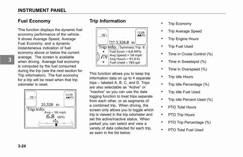
INSTRUMENT PANEL
Fuel Economy
This function displays the dynamic fueleconomy performance of the vehicle.It shows Average Speed, AverageFuel Economy, and a dynamicinstantaneous indication of fueleconomy above or below the currentaverage. The screen is availablewhen driving. Average fuel economyis computed by the fuel consumedduring the trip (see the next section forTrip information). The fuel economyfor a trip will be reset when that tripodometer is reset.
Trip Information
This function allows you to keep tripinformation data on up to 4 separatetrips – labeled A, B, C, and D. Tripsare also selectable as “Active” or“Inactive” so you can use the datalogging function to treat trips separatefrom each other, or as segments ofa combined trip. When driving, thescreen only allows you to toggle whichtrip is viewed in the trip odometer andset the active/inactive status. Whenparked you can select and view avariety of data collected for each trip,as seen in the list below:
• Trip Economy
• Trip Average Speed
• Trip Engine Hours
• Trip Fuel Used
• Time in Cruise Control (%)
• Time in Sweetspot (%)
• Time in Overspeed (%)
• Trip Idle Hours
• Trip Idle Percentage (%)
• Trip Idle Fuel Used
• Trip Idle Percent Used (%)
• PTO Total Hours
• PTO Trip Hours
• PTO Trip Percentage (%)
• PTO Total Fuel Used
3-24
3

INSTRUMENT PANEL
• PTO Trip Fuel Used
• PTO Trip Economy
The cluster mounted trip reset buttonis used to zero and clear accumulatedtrip data. Short presses togglebetween the odometer view, and the4 trips. Holding the button when on aparticular trip will zero the stored dataand also automatically set the clearedtrip to “active” status.
Using the MCS knob while in thisscreen will only activate or deactivatea trip function.
NOTEPTO options in the display will onlybe shown if the vehicle is equippedwith a PTO.
Truck Information
NOTEOnly available truck informationwill be shown (i.e., manualtransmissions do not have asoftware version).
This information is available when thevehicle is parked.
1. Chassis Information
a. Chassis Number
b. Fleet ID
c. CECU Software Version #
2. Engine Information
a. Engine Make
b. Engine Model
c. Engine Software Version
d. Governed Speed Limit
e. Engine Power
3. Transmission Information
a. Transmission Make
b. Transmission Model
c. Transmission SoftwareVersion #
4. ABS Information
a. ABS Make
b. ABS Model
c. ABS Software Version #
3-25
3

INSTRUMENT PANEL
Warning and Faults
The display has a message alertingfunction that overrides the normalviewing and navigation of functionswhen an issue occurs on the truck.These alert messages are called“pop-ups” because they take overthe screen. Some messages arelow enough priority that they canbe “suppressed”, which is done bypushing the MCS button. There willbe a screen indicator showing whichmessages are suppressible. If multiplepop-ups are present at the same time,they are viewed in a stack format, and
a spin of the MCS knob will allow youto see the different warnings. Thehighest priority warning defaults to thetop of the stack.
When the vehicle is parked, the“Warnings and Faults” function willaccess suppressed pop-ups that arecounted and presented in the upperleft corner of the screen.
By selecting “Review Warnings” thepop-up messages are recalled, andif multiple are active, the stack canbe navigated by spinning the MCSknob. The warning description can beviewed when driving or when parked
but the fault details are visible onlywhen parked. The menu selectionshown in the image above simply won’tbe there if the truck is driving, thoughthe warnings and tell-tale indicatorson the cluster will still be available asindicators if the problem is serious.Fault details screens include:
1. how many faults, shown in ascrollable stack format
2. which ECU the fault is beinggenerated from
3. a text description of the issue
4. it’s actual fault code
5. action instructions telling you whatto do (i.e. seek service soon vs.correct at next scheduled servicevisit)
3-26
3

INSTRUMENT PANEL
An example of a Fault Details screenis shown below:
Fault Details Example
Settings
This function is available only whenthe vehicle is parked.
Various settings may be changedusing this function. The operator canchange the time format (12hr/24hr),the time of day and alarm settings,units of measure for the display(mile/kilometer) and the languagebeing displayed. Changing settingsfunctions are typically done one of twoways. Items can be toggled straightfrom the highlighted selection (at thebranch level); these cases use darkblue text that changes to the set value.Others are menu selections that bringup new “leaf level” screens. Thefollowing shows examples of turningthe alarm on/off vs. screens that arenavigated to in order to set the clocktime.
To Turn Alarm ON/OFF:
1. When in the Settings Menu, scrollthrough the list of menu items to“Alarm”. Press the MCS.
2. Press the MCS to turn the alarmON or OFF.
To Set Clock Display Format:1. When in the Settings Menu, scroll
through the list of menu items to“Format”.
2. Press the MCS to display either 12hour (AM/PM) or 24 hour (military)time.
3-27
3

INSTRUMENT PANEL
To Set Home, Local or AlarmTime:
1. When in the Settings Menu, scrollthrough the list of menu items.
2. Press the MCS to select the itemto change.
3. Rotate the MCS knob to changethe hour. Press the MCS.
4. Rotate the MCS knob to changethe minutes. Press the MCS.
5. Rotate the MCS to toggle AM/PM.Press the MCS.
6. Press the button above the MCSto Exit.
Display Mode
The display off mode is available atany time in menu navigation, but thescreen minimize mode can only bedone when on this screen.
NOTEThere are times when the “DisplayOff” mode is not allowed orover-ridden by the system, forexample if a “pop-up” messageappears, the screen will turn backon, or if the truck is equipped with anadaptive cruise control system, thescreen cannot be turned off when itis active.
3-28
3

WARNING SYMBOLS
WARNING SYMBOLS
Guide to the WarningSymbols
The warning lights and audible alarmmay indicate a system malfunction.Check the lights frequently, andrespond properly as soon as you seeone go on. These lights could saveyou from a serious accident.
When multiple warning icons areshown on the instrument cluster,they will appear at first and thenminimize. When minimized theywill be represented in the activewarnings area of the display (seeDriver Performance Center on page3-14 for details). A triangle representsa warning registered and a diamondrepresents a check message.
WARNING
Do not ignore a warning light oraudible alarm. These signals tellyou something is wrong with yourvehicle. It could be a failure inan important system, such as thebrakes, which could lead to anaccident causing death or injury.Have the appropriate systemchecked immediately.
Check messages are provided to givethe operator additional informationregarding systems that requireattention due to a system malfunctionand/or operating conditions that mayhinder safe and proper performancefor the vehicle. The system will emita chime to alert the operator that amessage is appearing on the cluster.Some messages can be managed bythe operator while others may requirean authorized dealer repair.
The following is a list of WarningLight/Indicator Symbols that appearin the instrument cluster and DriverPerformance Center.
• the Symbol Name
• the appearance of the Symbol
• the Symbol Color when it isilluminated
• whether the symbol is standard(Std) or optional (Opt)
• whether the symbol has anassociated check message
• the Page Number reference foradditional information
Symbols are listed by major componentsections.
Example: Engine, and then inalphabetical order.
3-29
3

WARNING SYMBOLS
Warning Light/Indicator Symbols
Symbol Name Symbol Color Std/Opt Msg Page
1. Axle, Traction Control Yellow OPT on page 3-37
2. Brakes, Anti-Lock Brake System (ABS) Yellow STD on page 3-37
3. Brakes, Low Air Red STD on page 2-3
4. Brake, Park Brake Red STD on page 3-38
5. Brake, Service Brakes Red OPT on page 3-38
3-30
3

WARNING SYMBOLS
Symbol Name Symbol Color Std/Opt Msg Page
6. Brakes, Trailer Anti-Lock Brake System (ABS) Yellow STD on page 3-38
7. Differential, Inter Axle Diff Lock Yellow OPT on page 3-60.
8. Dump Truck, Body Up Red OPT on page 3-39
9. Dump Truck, Gate Yellow OPT on page 3-39
10. Dump Truck, Trailer Body Up Red OPT on page 3-39
11. Emissions, Diesel Particulate Filter (DPF) Yellow STD on page 3-39
3-31
3

WARNING SYMBOLS
Symbol Name Symbol Color Std/Opt Msg Page
12. Emissions, High Exhaust System Temperature (HEST) Yellow STD on page 3-39
13. Emissions, Malfunction Indicator Lamp (MIL) Yellow STD on page 3-40
14. Engine, Check Engine Yellow STD on page 3-40
15. Engine, Ether Start Green OPT on page 3-40
16. Engine, Engine Fan Green STD on page 3-40
17. Engine, Heater Yellow OPT on page 3-40
3-32
3

WARNING SYMBOLS
Symbol Name Symbol Color Std/Opt Msg Page
18. Engine, Low Coolant Level Yellow STD on page 3-40
19. Engine, Retarder (Brake) Green OPT on page 3-40
20. Engine, Stop Engine Red STD on page 3-40
21. Engine, Wait To Start Yellow OPT on page 3-41
22. Fuel, Water In Fuel (WIF) Yellow OPT on page 3-41
23. Lane Departure Warning (LDW) Yellow OPT on page 3-41
3-33
3

WARNING SYMBOLS
Symbol Name Symbol Color Std/Opt Msg Page
24. Lights, High Beam Blue STD on page 3-41
25. Power Take-off (PTO) Yellow OPT on page 3-41
26. Power Take-off (PTO), Pump Mode Green OPT on page 3-41
27. Refrigerator Green OPT on page 3-41
28. Seat Belt, Fasten Red STD on page 3-41
29. Suspension Dump Yellow STD on page 3-42
3-34
3

WARNING SYMBOLS
Symbol Name Symbol Color Std/Opt Msg Page
30. Tire Inflation Yellow OPT on page 3-42
31. Transmission, Auxiliary Yellow OPT on page 3-42
32. Transmission, Check Red OPT on page 3-42
33. Transmission, Retarder (may include BrakeSaver whenapplicable) Yellow OPT ● on page 3-42
34. Transmission, Service Transmission (Allison only) Yellow OPT ● on page 3-42
3-35
3

WARNING SYMBOLS
Symbol Name Symbol Color Std/Opt Msg Page
35. Turn Signal, Left Green STD on page 3-42
36. Turn Signal, Right Green STD on page 3-42
3-36
3

WARNING SYMBOLS
Description of WarningSymbols
1. Axle, Traction Control (ATC orAutomatic Traction Control)
A. Illuminates during the power-onself test when the ignition is turnedON. It turns off after a few seconds ifno system problems are detected. Ifan ATC problem is detected, the ATCWarning lamp will turn on and stay on.
B. Flashes when the ATC is regulatingwheel spin. (Refer to AutomaticTraction Control for more information.)
C. It blinks continuously when theDeep Snow & Mud switch is turned on,indicating that this feature is active.(Refer to Deep Snow and Mud Switchand Anti-Lock Braking System on page4-22 for more information.)
NOTEFor vehicles equipped withElectronic Stability Program, pleaserefer to additional material suppliedwith this operator manual, includedin your glove box informationalpacket.
WARNING
If this chassis is equipped with anelectronic stability program (ESP)and is modified (e.g. adding orremoving an axle, converting froma truck to a tractor, convertingfrom a tractor to a truck, changingthe body, lengthening of thewheelbase and/or frame, relocatingframe components, or modifyingpneumatic or electrical ABS/ESPharnesses) the ESP must bedisabled by a qualified technician.If you have any questions, contactyour authorized dealer. Failureto comply may result in death,personal injury, equipment orproperty damage.
2. Brakes, Anti-Lock Brake System(ABS)
Illuminates during the InstrumentationSystem Self Test. Have the ABSsystem checked by an authorized
3-37
3

WARNING SYMBOLS
dealer if the ABS Warning Lamp stayson for more than 3 seconds.
Illuminates during normal operatingconditions to indicate a problemwith the ABS System. See ABSWarning Lamps on page 4-22 for moreinformation.
Illuminates when a problem existswith the optional Wheel Spin Controlfeature. See Advanced ABS withStability Control on page 4-22 for moreinformation.
4. Brake, Park Brake
Illuminates in the status indicator whenparking brakes are applied.
5. Brake, Service Brake
Indicates that a fault exists in the brakesystem. This should be checked by anauthorized dealer as soon as possible.
6. Brakes, Trailer Anti-Lock BrakeSystem (ABS)
Illuminates during the InstrumentationSystem Self Test and the tractor/truckis connected with a ABS equippedtrailer.
Illuminates during normal operatingconditions to indicate a problemwith the Trailer ABS System. Thisshould be checked by an authorizeddealer as soon as possible. See ABSWarning Lamps on page 4-22 for moreinformation.
NOTETractors/Trucks and trailers builtafter 3/1/01 must be able to turnon an In-Cab Trailer ABS WarningLamp (per U.S. FMVSS121).The industry chose Power LineCommunication (PLC) as thestandard method to turn it on. SeeTrailer ABS Warning Lamp on page4-22 for more information. Ontrailers built prior to 3/1/01 verifytrailer ABS system status via therequired external warning lampmounted on the trailer. The indicatorlamp on the trailer should be yellowand identified with the letters “ABS”.
7. Differential, Inter Axle Diff Lock
Illuminates when the inter-axledifferential switch is ON thus lockingthe inter-axle differential. This powersthe forward rear and the rear rear
3-38
3

WARNING SYMBOLS
differentials equally. When the switchis turned off (inter-axle differentialunlocked) the engine power is allowedto flow to any of the 4 drive tires basedon the differential effect (mostly to theforward rear differential). (This featureis standard on all tandem axles).
8. Dump Truck, Body Up
Illuminates when Truck Dump Body isup.
9. Dump Truck, Gate
Illuminates when Truck Dump gate isopen.
10. Dump Truck, Trailer Body Up
Illuminates when Trailer Dump Bodyis up.
11. Emissions, Diesel ParticulateFilter (DPF)
Illuminates when diesel particulatefilter is plugged. This warning will alsoilluminate when regeneration operationis disabled.
12. Emissions, High ExhaustSystem Temperature (HEST)
Illuminates when the exhaust gastemperature and exhaust componentsbecome extremely hot.
Refer to the Engine Aftertreatmentcontrol operator manual for completeinstructions and warnings.
WARNING
If this light is on, do not park inan area of combustible vaporsor materials. You must keepcombustibles at least five (5) feetaway from the exhaust (outlet)stream (as it exits the tail pipe)while the HEST lamp is illuminated.Always park your vehicle outside.Failure to do so could ignite anexplosion or harm bystanders whichcould result in serious injury.
WARNING
If this light is on, do not park inan area where people are closeby. You must keep combustiblesat least five (5) feet away from theexhaust outlet while the HEST lampis illuminated. Failure to do so couldresult in serious injury.
3-39
3

WARNING SYMBOLS
WARNING
If this light is on, temperature ofthe tail pipe, exhaust pipes, dieselparticular filter (DPF), selectivecatalytic reduction (SCR) device andsurrounding components includingenclosures and steps becomeselevated during engine operationor any regeneration event and cancause serious burns to the skin.Allow adequate cooling time beforeapproaching, working on or nearany part of the exhaust system orsurrounding components.
13. Emissions, MalfunctionIndicator Lamp (MIL)
Illuminates when an engine emissionsfailure has occurred. The vehiclecan be safely driven but should beserviced to correct the problem. Thesituation should not be consideredan emergency. In some cases, theMalfunction Indicator Lamp will activate
in conjunction with the High ExhaustTemperature, Diesel Particulate Filter(DPF) and Diesel Emission Fluid(DEF) Warning Lights.
14. Engine, Check Engine
Illuminates when a non emissionsrelated problem exists, but the vehiclecan still be safely driven. Vehicleshould be serviced to correct theproblem but the situation should not beconsidered an emergency.
15. Engine, Ether Start
Illuminates when ether start switch ison.
16. Engine, Engine Fan
Illuminates when fan is active.
17. Engine, Heater
Illuminates when Engine Heater switchis on.
18. Engine, Low Coolant Level
Illuminates with an audible alarmindicating critically low coolant level.The vehicle must be serviced to correctthe problem but the situation shouldnot be considered an emergency.
19. Engine, Retarder (Brake)
Illuminates when the engine retarder(compression brake or exhaust brake)switch is turned on. (Engine retardersare an option.)
20. Engine, Stop Engine
Illuminates and an audible alarm tonewill sound when a major engine systemproblem exists.
3-40
3

WARNING SYMBOLS
WARNING
This should be considered anemergency. You should stopthe vehicle as safely as possibleand turn OFF the ignition. Thevehicle must be serviced and theproblem corrected before drivingagain. Failure to do so may causesevere engine damage or cause anaccident involving death or personalinjury.
21. Engine, Wait To Start
Illuminates when engine grid heateris on. (PACCAR PX-6, PX-8, andCummins ISL engines)
22. Fuel, Water In Fuel (WIF)
Illuminates when water has beendetected in the fuel.
23. Lane Departure Warning (LDW)
Illuminates when optional LDW systemis not able to track the vehicle'sposition within the lane.
NOTEFor vehicles equipped with LaneDeparture Warning, please refer toLane Departure Warning Driver'sGuide for additional information.
24. Lights, High Beam
Illuminates when the high beams areon. This icon will flash with audiblealarm if the headlamps are left onwhen the door is open. In addition, thisicon will flash, but without an audiblealarm, if there is a problem with thelow beam headlights or the low beamheadlight wiring. In such event, the
high beam headlights will turn on at50% normal brightness.
25. Power Take-off (PTO)
Illuminates when the PTO is engaged.
NOTEDo not drive vehicle with PTOengaged.
26. Power Take-off (PTO), PumpMode
Illuminates with remote throttleapplication. Indicates pump mode isactive.
27. Refrigerator
Illuminates to indicate that therefrigerator is on and ignition is off.
3-41
3

WARNING SYMBOLS
28. Seat Belt, Fasten
Illuminates when the ignition key isturned on as a reminder to fasten yourseat belt.
29. Suspension Dump
Illuminates when suspension air bagsare deflated.
30. Tire Inflation
Illuminates when tire pressures need tobe checked. (Tire Pressure MonitoringSystem is an option.)
31. Transmission, Auxiliary
Illuminates to indicate auxiliarytransmission is in neutral.
32. Transmission, Check
Illuminates when transmissionhas recorded a fault code. Thisicon may also appear in theTransmission Display menu of theDriver Performance Center. If the useris in this display menu, the icon doesnot indicate a fault code.
33. Transmission, Retarder(may include BrakeSaver whenapplicable)
Illuminates when BrakeSaver (exportonly) or Transmission Retarder isactive.
34. Transmission, ServiceTransmission (Allison only)
Illuminates when Allison 1000/2000transmission requires service.
35. Turn Signal, Left
Blinks when the left turn signal or thehazard light function is operating.
36. Turn Signal, Right
Blinks when the right turn signal or thehazard light function is operating.
3-42
3

OPTIONAL GAUGES
OPTIONAL GAUGES
Introduction
Listed here are gauges that may ormay not be on your dashboard orthe center instrument cluster. Forvehicles with a telematic navigationscreen, optional gauges will be part ofthe screen functions. Please refer tothe navigation system supplement forfurther details about its functions andhow it works.
Axle, Pusher Air Pressure
The Pusher Axle Air Pressure gauge(s)indicate the air pressure in the pusheraxle(s) suspension air bags. This iconmay have a numeral above the imageof the wheel to indicate which pusheraxle if there are multiple pusher axleson the vehicle.
Axle, Tag Air Pressure
The Tag Axle Air Pressure gaugeindicates the amount of air pressure inthe tag axle suspension air bags. Thisicon may have a numeral above theimage of the wheel to indicate whichpusher axle if there are multiple pusheraxles on the vehicle.
3-43
3

OPTIONAL GAUGES
Fuel Filter RestrictionPressure
This gauge tells you the conditionof the fuel filter by indicating therestriction from the fuel filter to the fuelpump. Check the engine manual forproper restriction. Replace the filterwith an approved filter only. Do notsubstitute the wrong micron element.
NOTEThe maximum allowable restrictioncould vary according to the typeor make of engine. Consult theengine manufacturers manual orengine dealer for fuel restrictionspecifications.
Air Filter RestrictionIndicator or Gauge
This gauge indicates the condition ofthe engine air cleaner and is measuredby inches of water (H2O). A clean filtershould register 7 in. H2O (may varywith system design) and a filter whoselife is over will register approximately25 in. H2O.
CAUTION
Continued operation with the AirFilter Restriction Gauge reading25 in. H2O may cause damage tothe engine. Inspect the filter andreplace if necessary. Holes in thepaper element render an air cleaneruseless and may cause the AirFilter Restriction Gauge to give afalse reading, even if the element isclogged. Replace the element if it isdamaged.
3-44
3

OPTIONAL GAUGES
Engine, Oil Pressure
It is important to maintain oil pressurewithin acceptable limits. If oil pressuredrops below the minimum psi a redwarning light in the gauge will turn on,the Stop Engine light will come on andan audible alarm tone will sound.
Engine, Oil Temperature
The Engine Oil Temperature gaugeindicates the engine oil temperature.If the oil temperature exceeds themaximum limits, a red warninglight in the gauge will turn on. Donot exceed maximum engine oiltemperature recommended by theengine manufacturer. (See the EngineOperation and Maintenance Manualfor details.)
Manifold Pressure Gauge
Your manifold pressure gaugeindicates the power your engine isputting out by showing the amount ofturbo boost. If the pressure indicatedby your manifold pressure gauge goesdown, there may be something wrongwith your engine. Have it checked by aqualified service person.
3-45
3

OPTIONAL GAUGES
Fuel Pressure Gauge
Your vehicle may also have a fuelpressure gauge.
WARNING
Do not carry additional fuelcontainers in your vehicle. Fuelcontainers, either full or empty, mayleak, explode, and cause or feeda fire, possibly causing death orpersonal injury. Do not carry extrafuel containers, even empty onesare dangerous.
Transmission TemperatureGauge
Your Transmission TemperatureGauge indicates the temperature ofthe oil in your transmission. Watchthis gauge to know when yourtransmission is overheating. If it is,have it checked by an authorizedservice representative.
Maximum transmission temperaturemay vary, depending upon thetransmission and type of lubricant.Check your transmission’s owner’smanual.
Drive Axle TemperatureGauge (Forward and Rear)
These gauges indicate the temperatureof the lubricant in your vehicle’s axle(s).These temperatures will vary withthe kind of load you are carrying andthe driving conditions you encounter.Maximum axle temperature may vary,depending upon the axle and typeof lubricant. Very high temperaturessignal a need to have your axle(s)lubrication checked.
3-46
3

OPTIONAL GAUGES
CAUTIONDriving with very hot temperaturesin your rear drive axles cancause serious damage to axlebearings and seals. Have your axlelubrication checked if you notice asign of overheating.
Suspension Load AirPressure, #1, #2
Suspension Load Air Pressure #1
Suspension Load Air Pressure #2
The Suspension Load Air Pressuregauge indicates the amount of airpressure in the air suspension air bags.
When the vehicle is equipped with dualleveling valves, the #1 gauge indicatesthe air pressure in the driver's side airbags. The #2 gauge indicates the airpressure in the passenger's side airbags.
Tractor Brake ApplicationAir Pressure
The Tractor Brake Application AirPressure gauge indicates the amountof air pressure applied to the tractorbrakes.
3-47
3

OPTIONAL GAUGES
Trailer Brake Application AirPressure
The Trailer Brake Application AirPressure gauge indicates the amountof air pressure applied to the trailerbrakes during brake foot valve and/orhand brake control valve applications.
Trailer Air Tank Air Pressure
The Trailer Air Tank Air Pressuregauge indicates the amount of airpressure in the trailer brake air tank.
Transfer Case OilTemperature
The Transfer Case Oil Temperaturegauge indicates the temperature ofthe oil in the transfer case. If the oiltemperature exceeds maximum limits,a red warning light in the gauge willturn on. Do not exceed maximumoil temperature recommended by themanufacturer. (See the Transfer CaseOperation and Maintenance Manualfor details.)
3-48
3

OPTIONAL GAUGES
Transmission OilTemperature, Auxiliary
The Auxiliary Transmission OilTemperature gauge indicates thetemperature of the oil in the auxiliarytransmission.
NOTEWatch this gauge to know when thetransmission is overheating.
Do not exceed maximum oiltemperature recommended by themanufacturer. (See the TransmissionOperation and Maintenance Manualfor details.)
Transmission Retarder OilTemperature
The Transmission Retarder OilTemperature gauge indicatesthe temperature of the oil in thetransmission retarder.
NOTEWatch this gauge to know when thetransmission is overheating.
Do not exceed maximum oiltemperature recommended by themanufacturer. (See the TransmissionOperation and Maintenance Manualfor details.)
3-49
3

SWITCHES
SWITCHES
Dash Switches
This custom vehicle will have a widevariety of switch controlled equipment.However, this particular vehicle may
not have every switch identified in thissection of the operator manual.
Some air device switches on thedash may require that the vehicleeither be at a specific speed, parkbrakes set or another device to beon or off for the air device to operate.
The instrument display will displayinformation regarding what needs tochange in order for the air device tooperate as expected.
The following table provides acomplete list of icons that may befound on the switch.
Dash Switches
Symbol Name Symbol Color Standard Option Page
1. Axle, Diff-Lock - Dual Amber ● See Axle, Diff-Lock - Dual on page 3-60.
2. Axle, Diff-Lock - Forward Rear Amber ● See Axle, Diff-Lock - Forward Rear on page3-60.
3. Axle, Diff-Lock - Steer Amber ● See Axle, Diff-Lock - Front on page 3-60.
4. Axle, Diff-Lock - Rear Rear Amber ● See Axle, Diff-Lock - Rear Rear on page 3-60.
3-50
3

SWITCHES
Symbol Name Symbol Color Standard Option Page
5. Axle, Diff-Lock - Single Rear Amber ● See Axle, Diff-Lock - Single Rear on page 3-60.
6. Axle, Inter-Axle Differential Locked (Tandem) Amber ● See Axle, Inter-Axle Differential Locked(Tandem) on page 3-60.
7. Axle, Two Speed Green ● See Axle, Two Speed on page 3-60.
8. Back Up Alarm Mute Amber ● See Back Up Alarm Mute on page 3-60.
9. Batteries, Low Voltage Disconnect (LVD) None ● See Batteries, Low Voltage Disconnect (LVD)on page 3-60.
10. Brakes, ABS Off-Road Amber ● See Brakes, ABS Off-Road on page 3-60.
11. Brakes, Parking Brake Valve Red ● See Brakes, Parking Brake Valve on page 3-60.
3-51
3

SWITCHES
Symbol Name Symbol Color Standard Option Page
12. Cab Dimmer Switch None ● See Cab Dimmer Switch on page 3-60.
13. Dump Truck Gate Red ● See Dump Truck Gate on page 3-60.
14. Engine, Brake Level None ● See Engine, Brake Level on page 3-60.
15. Engine, Brake On/Off Green ● See Engine, Brake On/Off on page 3-61.
16. Engine, Cruise Control On/Off Green ● See Engine, Cruise Control On/Off on page3-61.
17. Engine, Cruise Control Set/Resume None ● See Engine, Cruise Control Set/Resume onpage 3-61.
18. Engine, Ether Start (Optional) None ● See Engine, Ether Start on page 3-61.
3-52
3

SWITCHES
Symbol Name Symbol Color Standard Option Page
19. Engine, Fan Override Green ● See Engine, Fan Override on page 3-61.
20. Engine, Heater Green ● See Engine, Heater on page 3-62.
21. Engine, Remote Throttle Amber ● See Engine, Remote Throttle on page 3-62.
22. Engine, Shutdown None ● See Engine, Shutdown on page 3-62.
23. Engine, Under Hood Air Intake None ● See Engine, Under Hood Air Intake on page3-62.
24. Exhaust, Diesel Particulate Filter (DPF)Regeneration None ● See Exhaust, Diesel Particulate Filter (DPF)
Regeneration on page 3-62.
25. Fifth Wheel Slide Red ● See Fifth Wheel Slide on page 3-62.
3-53
3

SWITCHES
Symbol Name Symbol Color Standard Option Page
26. Fuel Heater Amber ● See Fuel Heater on page 3-62.
27. Generic Air, Accessory Green ● See Generic Air, Accessory on page 3-63.
28. Generic, Spare SPARE Green ● See Generic, Spare on page 3-63.
30. Lights, Auxiliary Green ● See Lights, Auxiliary on page 3-63.
31. Lights, Beacon Green ● See Lights, Beacon on page 3-63.
32. Lights, Daytime Running (Override) Green ● See Lights, Daytime Running on page 3-63.
33. Lights, Dome None ● See Lights, Dome on page 3-63.
3-54
3

SWITCHES
Symbol Name Symbol Color Standard Option Page
34. Lights, Lights, Exterior Lights Self Test None ● See Lights, Exterior Lights Self Test on page3-63.
35. Lights, Flood Amber ● See Lights, Flood on page 3-63.
36. Lights, Flood ISO 3732 Spare Amber ● See Lights, Flood ISO 3732 Spare on page3-64.
37. Lights, Fog Green ● See Lights, Fog on page 3-64.
38. Lights, Hazard Red ● See Lights, Hazard on page 3-64.
39. Lights, Headlight and Parking Lights None ● See Lights, Headlight on page 3-64.
40. Lights, Marker/Clearance None ● See Lights, Marker/Clearance on page 3-64.
3-55
3

SWITCHES
Symbol Name Symbol Color Standard Option Page
41. Lights, Marker/Clearance/Cab None ● See Lights, Marker/Clearance/Cab on page3-64.
42. Lights, Marker/Clearance/Trailer None ● See Lights, Marker/Clearance/Trailer on page3-65.
43. Lights, Spot Green ● See Lights, Spot on page 3-65.
44. Mud & Snow Traction Control None ● See Mud & Snow Traction Control on page3-65.
45. Power Take-off (PTO) Amber ● See Power Take-off (PTO) on page 3-65.
46. Power Take-off (PTO), Forward Amber ● See Power Take-off (PTO), Forward on page3-65.
47. Power Take-off (PTO), Rear Amber ● See Power Take-off (PTO), Rear on page 3-65.
3-56
3

SWITCHES
Symbol Name Symbol Color Standard Option Page
48. Roofdenser Green ● See Roofdenser on page 3-65.
49. Suspension, Axle, Pusher Green ● See Suspension, Axle, Pusher on page 3-65.
50. Suspension, Axle, Tag Green ● See Suspension, Axle, Tag on page 3-65.
51. Suspension, Dump Amber ● See Suspension, Dump on page 3-65.
52. Suspension, Lift Amber ● See Suspension, Lift on page 3-66.
53. Suspension, Third Axle Lift Green ● See Suspension, Third Axle Lift on page 3-66.
54. Pintle Hook Green ● See Tow Hook on page 3-66.
3-57
3

SWITCHES
Symbol Name Symbol Color Standard Option Page
55. Trailer, Axle (3rd Axle) Lift Green ● See Trailer, Axle (3rd Axle) Lift on page 3-66.
56. Trailer, Axle Lift Forward Green ● See Trailer, Axle Lift Forward on page 3-66.
57. Trailer, Axle Lift Rear Green ● See Trailer, Axle Lift Rear on page 3-66.
58. Trailer, Belly Dump Red ● See Trailer, Belly Dump on page 3-66.
59. Trailer, Dump Gate Red ● See Trailer, Dump Gate on page 3-66.
60. Trailer, Hotline Green ● See Trailer, Hotline on page 3-66.
61. Trailer, Suspension Air Dump Amber ● See Trailer, Suspension Air Dump on page3-66.
3-58
3

SWITCHES
Symbol Name Symbol Color Standard Option Page
62. Transmission, Transfer Case Amber ● See Transmission, Transfer Case on page3-66.
63. Transmission, Transfer Case 2 Speed Amber ● See Transmission, Transfer Case 2 Speed onpage 3-66.
64. Winch Clutch Green ● See Winch Clutch on page 3-66.
3-59
3

SWITCHES
1. Axle Diff-Lock - DualTurn switch on to engage Frontand Rear Axle Diff Lock.
2. Axle Diff-Lock - Forward RearTurn switch on to engage ForwardRear Axle Diff Lock.
3. Axle Diff Lock - SteerTurn switch on to engage FrontAxle Diff Lock.
4. Axle Diff-Lock Rear RearTurn switch on to engage RearRear Axle Diff Lock.
5. Axle Diff Lock - Single RearTurn switch on to engage SingleRear Axle Diff Lock.
6. Axle, Inter-Axle DifferentialLocked (Tandem)Turn switch on to engage Inter-AxleDifferential Lock.
7. Axle, Two SpeedIf equipped, the two speed axle switchallows you to select axle high and lowranges. The low range (Off) providesmaximum torque for operatingoff-highway. The high range (On) isa faster ratio for highway speeds.
8. Back Up Alarm MuteTurn switch on to mute BackUp Alarm.
NOTEThe mute function use isdiscouraged. Only use mute whenlegally required.
9. Batteries, Low VoltageDisconnect (LVD)If your vehicle is equipped with a LowVoltage Disconnect (LVD) feature,the LVD module is located insidethe driver's side kick panel.
10. Brakes, ABS Off-RoadTurn switch on to engage ABSOff-Road mode. See Anti-LockBraking System on page 4-22.
11. Brakes, Parking Brake ValvePull yellow knob to activate parkingbrakes. See Parking Brake Valveon page 4-35.
12. Cab Dimmer SwitchThis switch is used to alter thebrightness of the instrumentpanel lights.
NOTEThe Headlamp Switch is an "ON" or"OFF" switch. The panel lights areon full intensity during the day & goto Dimmer mode when headlampsare on.
13. Dump Truck GateTurn switch on to open DumpTruck Gate.
3-60
3

SWITCHES
14. Engine, Brake LevelIn the up position there will be 100%engine retarding. In the middleposition there will be 60% engineretarding. In the down position therewill be 33% engine retarding.For more information on whenand how to use the engine brakein your vehicle, see the enginebrake owner’s manual for additionalengine brake information.
15. Engine, Brake On/OffTurn switch on to activate EngineBrake system.For more information on whenand how to use the engine brakein your vehicle, see the enginebrake owner’s manual for additionalengine brake information.
16. Engine, Cruise Control On/OffTurn switch on to activate CruiseControl System.
17. Engine, Cruise ControlSet/ResumeThe Cruise Control Set/Resumeswitch allows you to SET the desiredspeed or RESUME the desiredspeed after the cruise control functionhas been interrupted.
WARNING
Do not operate the cruise controlwhen operating on road surfaceswith poor traction (wet, icy, or snowcovered roads) or in heavy traffic.Accelerations caused by the normaloperation of the cruise controlcould cause you to lose control ofthe vehicle resulting in an injuryaccident.
18. Engine, Ether Start (optional)Momentarily push switch in toactivate the Ether Start system.
19. Engine Fan OverrideThe engine fan switch allows youto control the engine fan manuallyor automatically. Please refer toEngine Fan Control on page 4-12for more information on how tooperate this switch.
WARNING
Do not work on or near the fan withthe engine running. Anyone nearthe engine fan when it turns on couldbe seriously injured. If it is set atMANUAL, the fan will turn on anytime the ignition key switch is turnedto the ON position. In AUTO, it couldengage suddenly without warning.Before turning on the ignition orswitching from AUTO to MANUAL,be sure no workers are near the fan.
3-61
3

SWITCHES
CAUTION
The fan or equipment near it couldbe damaged if the fan turns onsuddenly when you do not expect it.Keep all tools and equipment awayfrom the fan.
CAUTION
Do not operate the engine fan inthe MANUAL position for extendedperiods of time. The fan hub wasdesigned for intermittent operation.Sustained operation will shortenthe fan hub’s service life as well asreduce fuel economy.
20. Engine HeaterTurn switch on to activate theEngine Heater.
21. Engine, Remote ThrottleTurn switch on to activate RemoteThrottle Control.
22. Engine, ShutdownMomentarily push switch in toactivate the shutdown system.
23. Engine, Under Hood Air IntakeOperate this switch to controlwhether the engine intake is fromunder the hood or fresh air fromthe air inlet grille.
24. Exhaust, Diesel ParticulateFilter (DPF) Regeneration SwitchManually controls the dieselparticulate filter regeneration process.Refer to Engine After-treatmentControls Operator's Manual foradditional information.
25. Fifth Wheel SlideTurn switch on to “Unlock” FifthWheel Slide mechanism.The switch is guarded to protectyou from accidentally activatingor releasing the lock.
NOTEVehicles having an air slide fifthwheel have a fifth wheel sliderlock controlled by a switch onthe instrument panel. By placingthe switch in the unlock positionyou can slide the fifth wheel tovarious positions to adjust weightdistribution.
WARNING
Do not move the fifth wheel whilethe tractor-trailer is in motion. Yourload could shift suddenly, causingyou to lose control of the vehicle.Never operate the vehicle with theswitch in the UNLOCK position.Always inspect the fifth wheel afteryou lock the switch to be sure thefifth wheel slide lock is engaged.Failure to comply may result indeath, personal injury, equipment orproperty damage.
3-62
3
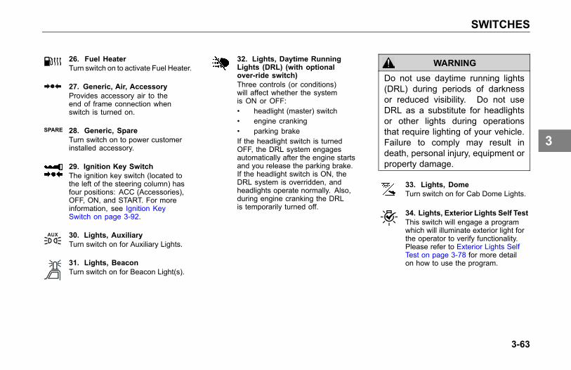
SWITCHES
26. Fuel HeaterTurn switch on to activate Fuel Heater.
27. Generic, Air, AccessoryProvides accessory air to theend of frame connection whenswitch is turned on.
SPARE 28. Generic, SpareTurn switch on to power customerinstalled accessory.
29. Ignition Key SwitchThe ignition key switch (located tothe left of the steering column) hasfour positions: ACC (Accessories),OFF, ON, and START. For moreinformation, see Ignition KeySwitch on page 3-92.
30. Lights, AuxiliaryTurn switch on for Auxiliary Lights.
31. Lights, BeaconTurn switch on for Beacon Light(s).
32. Lights, Daytime RunningLights (DRL) (with optionalover-ride switch)Three controls (or conditions)will affect whether the systemis ON or OFF:• headlight (master) switch• engine cranking• parking brakeIf the headlight switch is turnedOFF, the DRL system engagesautomatically after the engine startsand you release the parking brake.If the headlight switch is ON, theDRL system is overridden, andheadlights operate normally. Also,during engine cranking the DRLis temporarily turned off.
WARNING
Do not use daytime running lights(DRL) during periods of darknessor reduced visibility. Do not useDRL as a substitute for headlightsor other lights during operationsthat require lighting of your vehicle.Failure to comply may result indeath, personal injury, equipment orproperty damage.
33. Lights, DomeTurn switch on for Cab Dome Lights.
34. Lights, Exterior Lights Self TestThis switch will engage a programwhich will illuminate exterior light forthe operator to verify functionality.Please refer to Exterior Lights SelfTest on page 3-78 for more detailon how to use the program.
3-63
3

SWITCHES
35. Lights, FloodTurn switch on for cab mountedFlood Lights.
36. Lights, Flood ISO 3732 SpareTurn switch on for trailer mountedFlood Lights.
37. Lights, FogTurn switch on for Fog Lights.
NOTEAcross the U.S.A. and Canada,State/Provincial requirements varyas to when high beams and fog lightscan and cannot be used together.Some states allow only four lightsto be used together, while someallow more. How your lights arearranged will affect whether you canoperate headlights and fog lightsconcurrently—always comply withthe state or provincial requirementswhere you are driving.
38. Lights, HazardWith the switch in the ON position,the emergency flasher makes all fourturn signals (front and rear) flashsimultaneously. The flasher worksindependently of the ignition switch.You should always use the flasherif the vehicle is disabled or parkedunder emergency conditions.
WARNING
Use your Hazard Warning LightSystem any time you have to stop offthe road or on the side of the road,day or night. A hard-to-see vehiclecan result in an injury accident.Another vehicle could run into youif you do not set your flashers andfollow the placement of emergencysignals per FMCSR 392.22.
39. Lights, Headlight andParking LightsTurn switch on for headlights. Whenthe Headlights are ON, side, andtail lights are also on. This switchalso controls the park lights.
CAUTION
If you have confirmed there is aproblem in the low beam wiringcircuit, proceed with caution to thenext available exit/turnoff and safelypull your vehicle completely off theroad and call for assistance. Drivingyour vehicle with the headlamps onhigh beam (at reduced intensity)for a prolonged period could leadto an injury accident. Contact yournearest dealer to have the problemcorrected as soon as possible.
40. Lights, Marker/ClearanceTurn switch on to control Cab andVehicle Marker/Clearance lights.
NOTEAn interrupt switch for the trailermarker lights is mounted on the endof the turn signal lever.
3-64
3

SWITCHES
41. Lights, Marker/Clearance/CabTurn switch on to control CabMarker/Clearance lights separatelyfrom the trailer.
42. Lights,Marker/Clearance/TrailerTurn switch on to controlTrailer Marker/Clearance lightsseparately from the vehiclemarker/clearance lights.
43. Lights, SpotTurn switch on for Spot Light.
44. Mud & Snow Traction ControlMomentarily push switch in to engageTraction Control (TC).
45. Power Take-off (PTO)Turn switch on to engage PTO.Your vehicle may be equipped witha dash mounted switch that controlsPTO engagement/disengagement.When the operator activates theswitch for the PTO, the statusindicator lamp (located on theswitch) will immediately illuminateeven though PTO engagementmay not have occurred.If the PTO is engaged and theoperator turns the switch OFF, thePTO status indicator lamp (locatedon the switch) will go out immediatelyeven though PTO disengagementmay not have occurred.
NOTEActual PTO engagement/disengagement may be delayedmomentarily since it is controlledby the air system and mechanicalmovement.
CAUTION
Increasing engine RPM before thePTO is actually engaged couldprevent the PTO from engagingand/or cause PTO damage.
46. Power Take-off (PTO), ForwardTurn switch on to engageforward PTO.
47. Power Take-off (PTO), RearTurn switch on to engage Rear PTO.
48. RoofdenserTurn switch on for roof mountedcondenser fan.
49. Suspension, Axle, PusherTurn switch on to lower Single orForward Pusher Axle.
50. Suspension, Axle, TagTurn switch on to lower tag axle.
3-65
3

SWITCHES
51. Suspension, DumpTurn switch on to deflate suspensionair bags. The switch is guardedto protect you from accidentallydeflating the suspension.
WARNING
Do not operate the Air SuspensionDeflate Switch (Dump Valve) whiledriving. Sudden deflation while yourvehicle is moving can affect handlingand control and could lead to anaccident. Use this switch only whenyour vehicle is not moving.
CAUTION
Operating a vehicle with airsuspension bags either overinflatedor underinflated may cause damageto driveline components. If a vehiclemust be operated under suchconditions, do not exceed 5 mph (8km/h).
52. Suspension, LiftTurn switch on to over-inflatesuspension air bags. Turn switch offfor normal suspension height.
53. Suspension, Third Axle LiftTurn switch on to raise Third Axle.
54. Pintle HookTurn switch on to remove the slackfrom the Tow Hook.
55. Trailer, Axle (3rd Axle) LiftTurn switch on to lift 3rd Trailer Axle.
56. Trailer, Axle Lift ForwardTurn switch on to lift ForwardTrailer Axle.
57. Trailer, Axle Lift RearTurn switch on to lift Rear Trailer Axle.
58. Trailer, Belly DumpTurn switch on to open TrailerBelly Dump.
59. Trailer, Dump GateTurn switch on to open TrailerDump Gate.
60. Trailer HotlineTurn switch on to supply electricalpower to trailer accessories.
61. Trailer, Suspension Air DumpTurn switch on to deflate TrailerAir Suspension.
62. Transmission, Transfer CaseTurn switch on to shift thetransfer case.
63. Transmission, TransferCase 2 SpeedTurn switch on to shift the 2speed transfer case.
64. Winch ClutchTurn switch on to engageWinch Clutch.
3-66
3

SWITCHES
Controls On The SteeringColumnIntroduction
1. Tilt telescoping lever
2. Turn signal lever
3. Trailer hand brake
NOTEThe ignition key must be turned toON for the signal/switch to operate.
The turn signal lever is mounted on theleft side of the steering column. Thelever controls several functions: turn
signal, ID Clearance lights, high beamand windshield wiper control.
1. Tilt/Telescoping SteeringColumn
Depending on your vehicle’sconfiguration, you may have eithera Tilt/Telescoping or a fixed steeringcolumn.
• The tilt feature allows forward andrearward movement of the wheel.
• The telescoping feature allows youto move the wheel up and down.
To activate these features, locate theTilt/Telescoping lever.
3-67
3
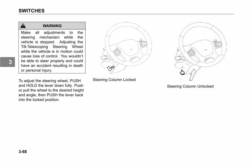
SWITCHES
WARNING
Make all adjustments to thesteering mechanism while thevehicle is stopped. Adjusting theTilt-Telescoping Steering Wheelwhile the vehicle is in motion couldcause loss of control. You wouldn’tbe able to steer properly and couldhave an accident resulting in deathor personal injury.
To adjust the steering wheel, PUSHand HOLD the lever down fully. Pushor pull the wheel to the desired heightand angle, then PUSH the lever backinto the locked position.
Steering Column Locked
Steering Column Unlocked
3-68
3

SWITCHES
2. Turn Signal/High BeamSwitch
NOTEThe ignition key must be turned toON for the signal/switch to operate.
The lever-action turn signal/high beamswitch is located on the left side of thesteering column.. Each time a turnindicator is activated the buzzer emitsa short beep.
Turn Signals
Turn Signal
• To signal a right turn, push thelever forward (clockwise).
• To signal a left turn, pull the leverback (counterclockwise).
• Each time the turn indicator isactivated the audible warningemits a short beep.
NOTEIf the vehicle turn signals and turnsignal indicators in the dash gaugecluster ever begin flashing at anaccelerated rate (115 cycles perminute) when the turn signal lever isin the OFF (center) position, or whena Right/Left turn has been selected,the problem may be related to afailed turn signal switch or turn signalmodule. In either case, the problemis not a failed bulb. Contact yournearest authorized dealer to havethe problem corrected as soon aspossible.
WARNING
After you complete a turn, shutthe system off by returning thelever to the “OFF” (center) position.Failure to shut off a turn signal couldconfuse other drivers and result inan injury accident. An indicator lightin the instrument panel will flash untilthe turn signal is turned off.
High Beam
NOTEThe headlights must be ON for thehigh beam switch to operate.
• To switch your headlights to loweror higher beam, gently pull the turnsignal lever, toward the steeringwheel, until you hear the switchclick and the beam changes.The blue indicator light in theinstrument panel will be ON whenthe high beam is being used.
3-69
3

SWITCHES
• To return to previous beam: pullthe lever towards the steeringwheel again.
• The high beams can bemomentarily flashed with orwithout the headlights being on.To flash the high beams, gentlypush the headlight lever away fromthe steering wheel to momentarilyturn on the lights.
NOTEContinued pressing of the highbeam flash will not keep the highbeams on.
Flash to pass
ID and Clearance Lights Flash
3-70
3

SWITCHES
Windshield Wipers/Washer
Your vehicle is equipped with atwo-speed, intermittent windshieldwiper system. The windshield wipersystem is integrated with the exteriorlights so that the low beam headlightswill turn on when the windshield wipersturn on. To override this function, turnthe headlights on and then off againand the low beams will turn off. Aseven-position rotary wiper switch(located on the turn signal lever)operates the windshield wipers andwasher. Rotate the end of the turnsignal lever to change the wiper mode.
NOTEThe ignition key must be turned toON or ACC for the wiper/washerswitches to operate.
Wiper/Washer
The first position after OFF is theintermittent #1 cycle. The nextpositions are intermittent #2, #3, and#4. The last two positions are wiperlow speed and wiper high speed.
To Wash The Windshield
Push the rotary wash/wipe knob in(towards steering column), hold formore than 0.8 seconds and thenrelease. Hold the knob in to extendthe washing cycle. After the leveris released, the wipers will shut offautomatically or resume the wiper’ssetting speed.
To activate the wipers for one swipewithout activating the washer (“mist”function), push the turn signal leverin (towards the steering column) andrelease in less than 0.5 seconds. Thewipers will perform a single swipe andthen resume the wiper’s setting speed.
WARNING
Clean blades regularly with a dampcloth to remove road film and waxbuild-up. Do not drive with worn ordirty wiper blades. They can reducevisibility, making driving hazardouswhich may lead to an injury accidentresulting in death or personal injury.
CAUTION
Do not use antifreeze or enginecoolant in the windshield washerreservoir - damage to seals andother components will result.
3-71
3

SWITCHES
CAUTION
If the electric pump is operated for along period (more than 15 seconds)with a dry reservoir, the pump motormay be damaged.
Check the windshield washing fluidlevel daily. If necessary, fill to top.
Clean all inside and outside windowsregularly. Use an alcohol-basedcleaning solution and wipe dry witheither a lint-free or a chamois cloth.Avoid running the wiper blades over adry windshield to prevent scratchingthe glass. Spray on washer fluid first.A scratched windshield will reducevisibility.
3. Trailer Brake Hand Valve
This hand valve, mounted on thesteering wheel column, provides airpressure to apply the trailer brakesonly. It operates independently ofthe foot treadle valve. See Using theBrake System on page 4-22, for moreinstructions on proper use of the TrailerBrake Hand Valve.
Steering Wheel Controls(Optional)
CAUTIONUnder no circumstances shouldyou attempt to service the steeringwheel, clockspring, or any of theelectrical wiring in the multiplexsystem, or any steering components(steering column, steering drivelineor steering gear). Tampering withthese components may result in aninoperable multiplex system.
This vehicle may be equipped with anoptional steering wheel with audio andcruise control button mounted on thespokes of the steering wheel.
3-72
3

SWITCHES
1. Left Switch Pod2. Horn3. Right Switch Pod
System Description
The steering wheel contains controlsfor commonly used functions so thatthe operator does not have to taketheir hands off of the steering wheel tooperate.
Operating the System
Horn - Depressing the bottom centerbar activates the electric horn.
Cruise Control - Vehicles with steeringwheel controls will have cruise controloptions on the right hand of thewheel instead of the switches on thedashboard. These optional switchesfor cruise control include a third switchto allow the operator to accelerate orcoast while maintaining cruise controloperation. For complete operatinginstructions, see Cruise Control onpage 4-37.
3-73
3

SWITCHES
Left Switch Pod
1. Audio Volume +/-2. Audio Seek +/-3. Audio Mute/Mode
Right Switch Pod
1. Cruise ControlOn/Off/Cancel
2. Cruise Control Set/Resume3. Cruise Control
Accelerate/Coast
WARNING
Do not operate the cruise controlwhen operating on road surfaceswith poor traction (wet, icy, or snowcovered roads) or in heavy traffic.Accelerations caused by the normaloperation of the cruise controlcould cause you to lose control ofthe vehicle resulting in an injuryaccident.
Horn
To use the electric horn, press thebutton in the center of the steeringwheel, which is the standard locationfor electric horns. Your vehicle may beequipped with air horns. To operate,pull on the lanyard extending from theoverhead header panel.
3-74
3

SWITCHES
Door Mounted ControlsIntroduction
If your vehicle is equipped with powermirrors, the mirror controls will belocated on the driver side door pad.Mirrors can be adjusted in 4 directions.
1. Heated Mirror Control2. Mirror Directional Control
Pad3. Mirror Selector Switch4. Door Lock/Unlock Switch5. Power Window Switch
WARNING
Adjust all mirrors before driving.Adjusting the mirrors while drivingcan cause you to take your eyesoff the road, which could result inan accident. Failure to do so couldlead to serious injury or equipmentdamage.
To provide good visibility, adjust themirror so the side of your vehicleappears in the inboard part of themirror.
3-75
3

SWITCHES
WARNING
Convex mirrors can distort imagesand make objects appear smallerand farther away than they reallyare. You could have an accident ifyou are too close to another vehicleor other object. Keep plenty ofspace between your vehicle andothers when you turn or changelanes. Remember that other objectsare closer than they may appear.
1. Mirror Heat Button
Your vehicle may be equipped withoptional heated mirrors. Mirror heatis controlled by the mirror heat switchbutton, which is part of the mirrorswitch module located on the driverside door pad.
NOTEThe Mirror Heat button also controlsthe optional hood mounted mirrorheat.
2. Power Mirror Switch
If your vehicle is equipped with powermirrors, the directional controls forboth mirrors are located near the top ofthe driver side door trim pad.
1. Move the mirror selector switchto the right or left from the neutralcenter position to select thedesired mirror for adjustment.
2. Depress the mirror directionalcontrol pad in one of its four arrowdirections to adjust the mirrorin/out or up/down.
NOTEAfter mirror adjustments have beencompleted, return the mirror selectorswitch back to the center (neutral)position to prevent unintentionaladjustments to the mirrors.
3-76
3

SWITCHES
After mirror adjustments have beencompleted, return the mirror selectorswitch back to the center (neutral)position to prevent unintentionaladjustments to the mirrors.
4. Power Door Lock Switch
Power door lock rocker switches arelocated on the door pads. To lock orunlock both cab doors as well as asleeper door, depress any door lockswitch at the end that displays a closedor open padlock symbol, respectively,on the switch face.
5. Power Window Switch
Power window rocker switches arelocated on the door pads. Depressthe switch to open the window or pullup on the switch to close the window.Release the switch to stop windowmovement. The drivers side windowhas an express down feature. Pushingon the switch all the way down until theswitch bumps will activate the expressdown feature. Release the button andthe window will continue to open until itis completely open.
3-77
3

SWITCHES
Exterior Lights Self Test
To start the Exterior Light Self-Test(ELST) feature:
1. Park the vehicle and set theparking brakes.
2. Insert the key into the ignition, startthe engine and allow the vehicleto run through its own Power OnSelf Test.
3. Press the momentary switch onthe dash to start the ELST.
This feature allows the operator toverify and inspect exterior lightingoperation typically performed during apre-trip inspection. When the featureis engaged, via a switch on the dash, itwill illuminate the:
• Park lights
• Side marker lights
• Hazard/turn signals
• Lo beam headlamps
• First set of fog/driving lights
The test will turn those lights off andthen illuminate the:
• Park lights
• Side marker lights
• Hi beam headlamps
• Stop/Brake lights
After turning these lights off, thesystem will resume testing the first setof lights. The light test will eventuallystop on its own. The operator mayinterrupt the test by turning the vehicleoff or pressing the switch a second timewhile the test is running. The operatorcan verify the light functionality byvisibly watching the light from outsidethe vehicle during the test or can readthe instrument cluster for any faultsdisplayed that are lighting related.
3-78
3

HEATING AND AIR CONDITIONING
HEATING AND AIRCONDITIONING
Air Conditioning Controls
1. Fan Control Dial2. AUTO Mode3. Temperature Control Dial4. MAX Defrost5. Dash & Floor6. Dash
7. Floor & Defrost8. Defrost9. Sleeper Override (for
vehicles with a sleeper)10. Floor11. Air Conditioner Enable
12. Fresh Air / Recirculate,Amber Indicator Light (On)
3-79
3

HEATING AND AIR CONDITIONING
Introduction
Your vehicle's air conditioning systemis capable of controlling the cabinair temperature automatically or ina manual override mode so thatthe driver may customize the airconditioner for specific needs (clearingfog or thin ice on the windshield).
When in Automatic mode the airconditioning system can aid coldvehicle startup procedures by utilizingthe fresh air/recirculated air optionwithout operator interaction. In somecases, the system will use fresh air toclear fog or thin ice on the windshieldor to warm up the cabin. In othersituations, the system may recirculateair to help cool ventilate a hot cab.
For vehicles with a sleeper, the front(cab) air conditioner control unit willalso have the capability for user toturn the sleeper controls on or off.The cab automatic air conditioner
unit is capable of controlling cabin airtemperature, however, the sleeper airconditioner will only vary the air supplytemperature relative to the temperaturein the air ducts.
The cab heater and A/C controls arelocated together in the center of thedash just to the right of the steeringcolumn.
WARNING
Do not drive with visibility reducedby fog, condensation, or froston the windshield. Your viewmay be obscured, which mayresult in death, personal injury,equipment or property damage.For clear visibility and safe drivingit is extremely important foryou to follow the instructionspertaining to the function anduse of the ventilation/heating anddefogging/defrosting system. Ifin doubt, consult your dealer.Maximum heating output and fastdefrosting can be obtained only afterthe engine has reached operatingtemperature.
3-80
3
HEATING AND AIR CONDITIONING
WARNING
Exhaust fumes from the enginecontain carbon monoxide, acolorless and odorless gas. Do notbreathe the engine exhaust gas.A poorly maintained, damaged orcorroded exhaust system can allowcarbon monoxide to enter the cab.Entry of carbon monoxide into thecab is also possible from othervehicles nearby. Failure to properlymaintain your vehicle could causecarbon monoxide to enter the cab,resulting in death or personal injury.
WARNING
Never idle your vehicle for prolongedperiods of time if you sense thatexhaust fumes are entering the cab.Investigate the cause of the fumesand correct it as soon as possible.If the vehicle must be driven underthese conditions, drive only with thewindows open. Failure to repairthe source of the exhaust fumesmay result in death, personal injury,equipment or property damage.
NOTEKeep the engine exhaust systemand the vehicles cab ventilationsystem properly maintained. It isrecommended that the vehiclesexhaust system and cab beinspected:
• By a competent technician every15,000 miles
• Whenever a change is noticed inthe sound of the exhaust system
• Whenever the exhaust system,underbody, or cab is damaged
NOTETo allow for proper operation of thevehicle ventilation system, keepthe inlet grille at the base of thewindshield clear of snow, ice, leavesand other obstructions at all times.
3-81
3

HEATING AND AIR CONDITIONING
CAUTIONDo not stay in the vehicle with theengine running or idling for morethan 10 minutes with the vehicle'sHeater and A/C ventilation systemin RECIRC or at LOW FAN SPEED.Even with the ventilation system on,running the engine while parked orstopped for prolonged periods oftime is not recommended.
NOTEWhen idling for short periods of time:
• Set the heating or cooling systemto Heat or A/C
• Set the fan to Medium or Highspeed
• Set the controls to FRESH AIR
NOTEIf you are required to idle yourvehicle for long periods of time,install an auxiliary heater orautomatic idle control. Theseauxiliary devices can reduce fuelconsumption and save you money.
NOTEIf you are parked next to idlingvehicles, move your vehicle or donot stay in your vehicle for prolongedperiods of time.
Automatic Air Conditioning
Your vehicle’s air conditioning systemhas an automatic function that canmanage the cabin air temperatureto the setting on the control unit. Inautomatic mode, the air conditionerchanges the air distribution, outlettemperature, and fan speed basedon the temperature setting selected,the amount of sunlight it senses fromthe dash board sensor and the cabintemperature determined from thetemperature sensor on the front of thecontrol head. The button that enablesautomatic mode is labeled AUTO.
3-82
3

HEATING AND AIR CONDITIONING
1 Sunlight Sensor
Pressing the AUTO button will enablethe automatic air conditioning system.The operator only needs to set thetemperature via the temperaturecontrol knob in the center. Thesystem will dynamically adjust varioussettings to obtain the desired cabintemperature.
If the air conditioner is using fresh air inAUTO mode, the operator may selectrecirculated air to avoid temporaryexternal odors or pollution withoutexiting AUTO mode.
The system may have difficultiesin obtaining the desired cabintemperature if the temperature settingis repeatedly changed.
NOTEThe system has two sensors, one onthe dash and one on the control unit.Be sure neither of these sensors isblocked.
Semi-Automatic ControlMode
If user changes airflow mode duringAUTO function the airflow modeindicator will light and the airflowfunction will go to the requested airflowlocation, however the fan speedand temperature will continue to becontrolled in AUTO function.
If user changes fan speed duringAUTO function the fan speed indicatorwill light and the fan function will goto the selected fan speed, howeverairflow mode and temperature willcontinue to be controlled in AUTOfunction.
3-83
3

HEATING AND AIR CONDITIONING
MAX Defrost
The air conditioner’s MAX Defrostfunction automatically distributesoutside air through the windshielddefroster vents and de-mistervents. The AC compressor willalso be engaged when the outsidetemperature is above 34ºF (1ºC) toremove humidity from the air. Fresh airand hi fan speed settings will result inthe fastest reduction in fog or thin ice.This function is enabled by pressingthe MAX button.
In this mode, the operator has theoption of what temperature setting isused during MAX operation. Increasethe temperature to improve the speedof fog or thin ice removal from yourwindshield. When utilizing MAX
Defrost the system will not allow the airto be recirculated.
When utilizing Max Defrost, the systemwill not allow the compressor to beturned off by the user.
Manual Override
The air conditioner will also allow theoperator to override the automaticfunction. The operator may overridethe system by either:
• Pressing the AUTO button again
• Rotating any fan speed or airdistribution knob
• Pressing the A/C button
• Pressing the MAX button
3-84
3

HEATING AND AIR CONDITIONING
What Each Control Does
Fan Speed Adjustment
Turning this dial clockwise from the OFFposition turns the fan ON and increases thefan speed.
Air Flow Control DialThis dial directs the air flow through 5 primarysets of vents:
Instrument Panel and De-misterVents
Instrument Panel, De-mister andFloor Vents
Floor and De-mister Vents
Floor, De-mister Vents and*Defrost Vents
*Defrost and De-mister Vents
*Fresh air and air conditioning areautomatically turned ON.
Temperature Control Dial
Turn this dial clockwise for heat,counterclockwise for cool.
Air Conditioner Switch
This button turns the A/C compressor onand off. When using the Max Def functionthe user will not be able to turn off the ACcompressor with this button.
NOTEFan Control Dial must also be in theON position for A/C to be on. A/Cengages automatically in AUTO,defrost and floor/defrost.
Fresh Air/Recirculation Switch
This switch controls the source of the airflowing into the heater and air conditionerunitRecirculated air may reduce the amount oftime needed to cool down the interior of thevehicle (when used with A/C) and may alsohelp reduce undesired outside odors fromreaching the interior of the vehicle. Thisbutton can be engaged manually in anynon-defrost modes.
NOTEYou may notice changes in soundbetween recirculated mode andother airflow modes.
3-85
3

HEATING AND AIR CONDITIONING
Sleeper Override Switch (forvehicles with a sleeper)
Press this button if the user wants to controlthe on/off function of the sleeper heating andair conditioning unit.Using this button does not allow this controlunit to control sleeper blower speed orsleeper temperature. It only turns the sleeperheating and air conditioning unit on or off.
Operating tips whenoverriding automaticcontrols
An air conditioner can reduce fog buildup on the windshield by setting it to thedefrost or the floor/defrost air selection.To increase the effectiveness of theair conditioner, use the A/C buttonin the ON position, increase the airtemperature setting and/or increasethe fan speed.
If the cabin becomes humid or damp,use the air conditioner with the fanon, with fresh air (not in recirculate airmode) and the A/C in the ON positionto dry the cabin air.
In situations where more cooling ofthe cab is required, make sure thesystem is in the recirculation mode.This setting will be more effective thanusing fresh air.
How To Use The System
The engine must be running for theheater and air conditioner to generatehot and cold air.
To Cool - Manually
Push the Fresh Air/RecirculationSwitch to the Fresh Air mode(Blue indicator light off). Manuallysetting the system to recirculateair will increase the effectivenessand uses the least amount of fuel.
Turn ON the Fan Control Dial tothe desired fan speed.
Turn Temperature Dial to Desired Setting.
Turn the Air Flow Control Dial toDash Vents.
3-86
3

HEATING AND AIR CONDITIONING
If the outside air is not cold enoughto cool the cab, press to engagethe compressor which will delivercolder air.
For more cooling effect, you mayneed to press the switch back torecirculation mode.
To Heat
Turn the Fan Control Dial ON tothe desired fan speed.
Turn the Air Flow Control Dial toFloor Vents.
Adjust the Temperature Control Dialclockwise until the air temperaturefeels comfortable.
Using this function in "manual" modewill provide the maximum heatingperformance.
To Dehumidify
Push the Fresh Air/RecirculateSwitch to the Fresh Air mode (Blueindicator light off).
Turn ON the Air ConditioningSwitch (Blue indicator light on).
Turn ON the Fan Control Dial tothe desired fan speed.
Adjust the Temperature ControlDial until the air temperature feelscomfortable.
The air conditioner removes moisturefrom the air while the heater heats theair.
3-87
3

HEATING AND AIR CONDITIONING
To Defog and Defrost theWindshield
Turn the FanControl Dial clockwiseto the highest fan speed.
Turn the Air Flow Control Dial toDefrost Vents.
Fresh air and air conditioning areautomatically turned ON.
Adjust the Temperature Control Dialclockwise to full heat.
CAUTIONDuring extreme cold weather, donot blow hot defroster air onto coldwindshields. This could crack theglass. Turn the Air Flow Control Dialto Defrost and adjust the fan speedaccordingly while the engine warms.If the engine is already warm, movethe Temperature Control Dial tocool, then gradually increase thetemperature when you see thatthe windshield is starting to warmup. Failure to comply may result inequipment damage.
Sleeper Heater - A/CControls (optional)
A separate switch on the dash HVACunit will send power to the “bunk” orsleeper control unit The button on thecab HVAC unit must be pressed andin the on mode to use the sleepercontrols. The sleeper control unit hasthree controls:
1. Air speed control
2. Air conditioner compressor on/off
3. Air temperature control
Unlike the cabin air temperaturecontrols, the sleeper temperaturecontrol will alter the air temperaturebased on the knob setting. TheTemperature Control is not keyedto specific temperatures. Turning
3-88
3

HEATING AND AIR CONDITIONING
counterclockwise means cooler thanit is now. Clockwise means warmerthan it is now. Once the desiredtemperature is reached, the systemwill maintain it automatically.
NOTEThe sensor is located on thesleeper heater - A/C control paneland measures the sleeper airtemperature at the panel. Therewill be a time delay betweenTemperature Control adjustmentand sleeper air temperature change.Also, be careful of any heatsource which could affect the airtemperature by the sensor. Avoidhanging items (e.g. shirt, jacket,etc.) which could block the air flowto the sensor.
3-89
3

ACCESSORIES
ACCESSORIES
Radio (Option)
As an option, your vehicle has eitheran AM/FM Stereo Receiver, which mayor may not have a CD, or may havethe stereo system integrated with yourNavigation and telematics unit.
Other radio options include a bluetoothor satellite receiver.
For instructions on how to operate yourparticular radio, see the supplementaloperating manual for those units.
Cigarette Lighter andAshtray (Option)
NOTEThe cigarette lighter will operate withthe ignition key in either the OFF,ACC (accessory), or ON position.
This vehicle comes standard with twocupholders and power ports locatedin the center of the dashboard. Thisvehicle may have the optional ashtrayinsert (for the cupholder) and theoptional cigarette lighter in a powerport.
To operate, push in on the knob endof the lighter. After a few moments,the lighter will automatically pop out,glowing hot and ready to use. Afteruse, insert the lighter back into thesocket without pushing all the way in.
The socket of the cigarette lighter maybe used to operate 12 volt, 15 ampere
appliances, such as a hand spotlightor small vacuum cleaner.
WARNING
Do not place paper or othercombustible substances in anashtray, it could cause a fire. Keepall burnable materials, besidessmoking materials, out of theashtray. Failure to comply mayresult in death, personal injury,equipment or property damage.
WARNING
Do not exceed thevoltage/amperage capacity of thecigarette lighter. It could result ina fire. Follow all warnings andinstructions in the operator's manualfor the appliance you are using.Failure to comply may result indeath, personal injury, equipment orproperty damage.
3-90
3

ACCESSORIES
Cab StorageGlove Box
A glove box is provided to storeimportant documents, the vehicleliterature set (including this Operator'sManual) and other related materials.
WARNING
Do not drive with the glove box open,it can be dangerous. In an accidentor sudden stop, you or a passengercould be thrown against the coverand be injured. To reduce the riskof personal injury during an accidentor sudden stop, keep the glove boxclosed when the vehicle is in motion.
You can choose from a variety of otherinterior storage options to store yourpersonal supplies or small tools:
- center console
- map pocket on the door
- overhead storage compartments
WARNING
Do not carry loose objects in yourcab, it can be dangerous. In asudden stop, or even going overa bump in the road, they could flythrough the air and strike you or apassenger. You could be injuredor even killed. Secure all looseobjects in the cab before moving thevehicle. Carry any heavy objectssuch as luggage in the exteriorstorage compartment and close itsecurely.
Appliances
If your vehicle is equipped with atelevision, or other appliance, be surethey are compatible with your vehicle'selectrical system. Secure them in thecab so they cannot come loose in asudden stop.
WARNING
In a sudden stop or collision a heavyobject in your cab could strike youor anyone with you. You could beinjured or even killed. Secure anyappliance (such as a radio, or TV)you add to your sleeper or cab.
3-91
3

ACCESSORIES
Ignition Key Switch
The ignition key switch (located to theleft of the steering column) has fourpositions: ACC (Accessories), OFF,ON, and START.
OFF: In this position all accessoriesare OFF (except those listed below)and you can remove the key.
The following lights and accessorieshave power when the key is in the OFFposition:
• brake lights
• emergency hazard flasher
• dome and courtesy lamps (ondoors)
• electric horn
• cigarette lighter
• tail lights
• marker lamps
• headlights
• radio station memory
• instrument lights
• auxiliary power
• Instrument panel memory settings
ACC (Accessory): With the key in thisposition you can play the radio, defrostmirrors (if equipped with mirror heat)or use other accessories.
ON: In the ON position all circuits areenergized. Panel warning lights willlight and the buzzer will sound until(1) the engine is started, (2) normal oiloperating pressure is reached, and (3)air brake system pressure is above65 psi (441 kPa). In this position, theignition key cannot be removed.
START: Turn the key to this positionto start your engine. Release thekey after the engine has started. Forcomplete engine starting procedures,see Operating The Engine on page4-5.
3-92
3

ACCESSORIES
Vehicle Telematic System
Your vehicle may be equipped withan onboard telematics system. Thissystem is a Global Positioning Satellite(GPS)-linked computer. It receivesinput from multiple sources to locateyour vehicle. Read and understandthe Supplemental Telematics andNavigation System Owner’s Manualand observe the Warnings, Cautions,and Notes that follow before using thesystem.
WARNING
Verify legal weight and heightrestrictions for the route suggestedby the telematic system. Failure toverify height restrictions could leadto causing death, personal injury orproperty damage. Failure to verifyweight restrictions could result in atraffic infraction.
WARNING
Only glance at the system monitorwhile driving. Prolonged periods ofviewing while driving could resultin an accident involving death orpersonal injury.
WARNING
Do not program the telematicsystem while driving. Always stopyour vehicle when programmingor changing the settings on thetelematic system. Programming thesystem while driving can cause youto take your eyes off the road, whichcould result in an accident involvingdeath, personal injury or equipmentdamage.
WARNING
Regardless of how and where thenavigation system directs you, it isyour responsibility to operate thevehicle in a safe and legal manner.Failure to comply may result indeath, personal injury, equipment orproperty damage.
WARNING
Ensure the volume level of allaudio devices is set to a level thatstill allows you to hear outsidetraffic and emergency vehicles.Failure to comply may result indeath, personal injury, equipment orproperty damage.
3-93
3

ACCESSORIES
CAUTIONDo not rely on the telematicsystem to route you to the closestemergency services. Not allemergency services are in thedatabase.
NOTEThe map database is the mostcurrent available at the time ofproduction. The database isdesigned to provide you withroute suggestions and does nottake into account the relativesafety of a suggested route or offactors that may affect the timerequired to reach your destination.See the Supplemental NavigationSystem Owner’s Manual for moreinformation.
Care of the Display Screen
From time to time it may be necessaryto clean the display screen. To cleanthe screen, dampen a clean, soft,lint-free cloth with water only. A mildglass cleaner that does not containalcohol or ammonia may also beused. Cleaners that contain alcoholand/or ammonia will eventually dry-out,crack and "yellow" the screen. Wipethe screen gently back and forth. Youcan also use a commercial cleanerespecially designed for LCD screens.
Screen Display On/Off
1. Press and hold the POWER/LIGHTbutton for approximately 1 second.
2. After the display has been turnedon, the following Warning/Informationalscreen will appear:
3-94
3

ACCESSORIES
Warning/Informational Screen
WARNINGDo not let this device distract you whiledriving. Always concentrate on yourdriving. Distractions could cause anaccident resulting in injuries to you orothers.IMPORTANTDisclaimer: Map data may be inaccurate andnavigation routes may not be available forlarger size vehicles.Regardless of how and where the navigationsystem directs you, it is your responsibilityto operate the vehicle in a safe and legalmanner.Note: Before using this system, readthe Owner's Manual and learn how itoperates. Some functions of this systemwill not operate when the truck is moving.
3. After reading the information, touchthe TTT in the upper right corner of thescreen with your finger indicating youacknowledge and understand theinformation. The MENU screen willautomatically appear next.
4. To turn the system off, press andhold the POWER/LIGHT button for 3seconds.
Disclaimer
The vehicle manufacturer is notresponsible for erroneous map data,misrouting or any downtime or otherdamages associated with or arising outof the use of the Navigation System.
Passenger Side 'down'Mirror
A mirror is located above thepassenger door that provides a quickview of the blind spot created by thepassenger door.
3-95
3

ACCESSORIES
Rotate the mirror up or down to get thedesired view.
3-96
3

STARTING & OPERATING
STARTING & OPERATINGIntroduction . . . . . . . . . . . . . . . . . . 4-5Normal Weather . . . . . . . . . . . . . . . . 4-5Cold Weather . . . . . . . . . . . . . . . . . 4-6Engine Block Heater (Option). . . . . . . . . . . 4-6Engine Warm-up . . . . . . . . . . . . . . . . 4-7Ether Metering Equipment . . . . . . . . . . . 4-10
OPERATING THE ENGINEStationary PTO Operation . . . . . . . . . . . 4-12Engine Fan Control . . . . . . . . . . . . . . 4-12Winterfronts . . . . . . . . . . . . . . . . . 4-13Engine Control Display . . . . . . . . . . . . 4-14
OPERATING THE TRANSMISSIONOperating Hydraulic Clutch (Manual Transmission) 4-15Operating Manual Transmissions . . . . . . . . 4-15Putting the Vehicle in Motion . . . . . . . . . . 4-16Automatic and Automated Transmissions . . . . 4-19
4-1
4

STARTING & OPERATING
Auxiliary Transmission . . . . . . . . . . . . . 4-20More Transmission Tips . . . . . . . . . . . . 4-20
OPERATING THE BRAKE SYSTEMIntroduction . . . . . . . . . . . . . . . . . 4-22Retarders . . . . . . . . . . . . . . . . . . 4-33Parking Brake . . . . . . . . . . . . . . . . 4-35
CRUISE CONTROLCruise Control Switch . . . . . . . . . . . . . 4-37Adaptive Cruise Control (Optional) . . . . . . . 4-39
AXLEDifferential Lock . . . . . . . . . . . . . . . 4-42Dual Range (Two-Speed) Rear Axle . . . . . . . 4-43Auxiliary Axles - Pusher or Tag . . . . . . . . . 4-45
SUSPENSIONAir Suspension Height/Air Pressure . . . . . . . 4-52Driving with Deflated Air Springs . . . . . . . . 4-53
4-2
4

STARTING & OPERATING
AFTER-TREATMENT SYSTEMIntroduction . . . . . . . . . . . . . . . . . 4-54
DRIVING TIPS AND TECHNIQUESIntroduction . . . . . . . . . . . . . . . . . 4-55Coasting . . . . . . . . . . . . . . . . . . . 4-55Descending a Grade . . . . . . . . . . . . . 4-56Engine Overspeed . . . . . . . . . . . . . . 4-56Fuel - Excess Consumption . . . . . . . . . . 4-59
SLEEPER BUNKSSleeper Bunk. . . . . . . . . . . . . . . . . 4-61
STOPPING THE ENGINEBefore Stopping the Engine . . . . . . . . . . 4-63Refueling . . . . . . . . . . . . . . . . . . 4-63Refuel Before the Final Stop . . . . . . . . . . 4-64Final Stop . . . . . . . . . . . . . . . . . . 4-65
4-3
4


STARTING & OPERATING
STARTING &OPERATING
Introduction
Since each vehicle iscustom-equipped, all engine operationinstructions in this manual are general.You will want to consult the manual foryour engine to find out details aboutyour specific engine’s needs. Youmay need to use a slightly differentprocedure from the one outlined here.
Below are instructions for bothnormal-temperature starting andcold-weather starting.
Normal Weather
When the outside temperature isabove 50° F (10° C), you can use thefollowing procedure.
1. Set the parking brake.
2. Put your main transmission inNeutral.
3. Disengage (depress) the clutch(with manual transmission).
4. Turn the key switch to ON.
CAUTIONNever operate the starter motorwhile the engine is running. Thestarter and flywheel gears couldclash or jam, severely damagingthem.
NOTESome starters are equipped withovercrank protection. Check the“Engine Operation and MaintenanceManual” for details.
5. Turn the ignition key to the STARTposition. If the engine does notstart within 30 seconds, releasethe ignition switch. To avoidovertaxing the starter motor orthe batteries, don’t use the starterfor more than 30 seconds. Letthe starter motor cool and thebatteries recover for two minutesbefore trying again.If the engine still won’t start after acouple of tries, check the fuel linesfor possible fuel starvation or airleaks. Starting failure may meanfuel isn’t reaching the injectors.
6. As soon as the engine starts, beginto watch the oil pressure gauge.Check your engine manufacturer’s
4-5
4
STARTING & OPERATING
manual for the right pressure foryour engine. If the oil pressuredoesn’t rise within a few seconds,stop the engine. Find out whatis wrong before restarting theengine.
7. Slowly engage (release) the clutchafter the engine has started.
8. Wait for the oil pressure gauge toreach normal operating pressurebefore operating the vehicle oridling faster than 1000 rpm.
Cold Weather
In cold weather, fast engine startinghelps relieve the loads on the electricalsystem and cranking motor. Using thespecial cold starting equipment willhelp starting. If you follow a few simpleguidelines, you will extend the servicelife of your engine.
• Keep the electrical system in topcondition.
• Use the best quality fuel of therecommended grade.
• Use recommended enginelubricating oil.
• Fully depress the acceleratorpedal after engaging the starter.
• For manual transmissions andauxiliary transmissions, leave thetransmission in neutral and allowthe transmission lubricating oilto warm up (approximately 3-5minutes) before operating vehicle.
Engine Block Heater(Option)
To preheat the engine before starting,plug the optional engine block heaterinto a properly grounded AC electricalsource. Do not start the engine withthe heater plugged in.
WARNING
Engine block heaters can causefires which may result in death,injury and/or property damageif not properly maintained andoperated. Regularly inspect theengine block heater wiring andconnector for damaged or frayedwires. Do not use the heater ifthere are any signs of problems.Contact your authorized dealer orthe manufacturer of the heater if youare in need of repairs or information.
4-6
4

STARTING & OPERATING
CAUTION
Always unplug heater before startingthe engine. Damage to the coolingsystem could occur if the heater isnot turned OFF (unplugged).
Depending on engine make, when thetemperature falls below -10° F (-24°C), the block heater is required.
• Use a solution of half ethyleneglycol antifreeze and half water forbest heater performance. Do notexceed 65 percent concentrationof antifreeze, as a shortenedheater life will result. See EngineCooling System on page 5-71, formore information.
• After servicing the cooling system,operate the vehicle for a day or twobefore using the heater. Trappedair inside the engine needs timeto escape.
Engine Warm-upEngine
The purpose of engine warm-up is toallow oil film to be established betweenpistons and liners, shafts and bearingswhile your engine gradually reachesoperating temperature.
Warm-up Procedure1. After you’ve started your engine,
idle it at approximately 600 RPMwhile you check:
a. oil pressure
b. air pressure
c. alternator output
2. After a few minutes of idling at600 RPM, increase your idlespeed to 900 or 1000 RPM.Continue your warm-up. Thisprocedure allows oil to warm andflow freely while pistons, liners,shafts, and bearings expand
slowly and evenly. In extremelycold temperatures, you may haveto increase idle speed.
NOTEIn colder climates where thetemperature is often below freezing,the warm-up for turbochargedengines is especially important.Chilled external oil lines leading tothe turbocharger will slow the oilflow until the oil warms, reducing oilavailable for the bearings. Watchthe engine oil temperature orpressure gauge for a warming trendbefore increasing engine idle speed(RPM).
3. Continue the engine warm-up untilthe coolant temperature reachesat least 130° F (54° C). At thistemperature, you can use partialthrottle. Wait until the coolanttemperature is at least 160° F (71°C) before operating at full throttle.
4-7
4

STARTING & OPERATING
WARNING
Exhaust fumes from the enginecontain carbon monoxide, acolorless and odorless gas. Apoorly maintained, damaged, orcorroded exhaust system can allowcarbon monoxide to enter the cab orsleeper. Failure to properly maintainyour vehicle could cause carbonmonoxide to enter the cab andcause death or personal injury.
WARNING
Never idle your vehicle for prolongedperiods of time if you sense thatexhaust fumes are entering the cab.Investigate the cause of the fumesand correct it as soon as possible.If the vehicle must be driven underthese conditions, drive only withthe windows slightly open. Failureto repair the source of the exhaustfumes may lead to death or personalinjury.
CAUTION
The use of a winterfront can resultin excessive engine coolant, oil, andcharge air (intake) temperatures,which can lead to overheating andpossible engine damage. If youmust use a winterfront:
• Refer to the “Engine Operationand Maintenance Manual”for operating restrictions andrecommendations.
• Use only a winterfront availablefrom your dealer that iscompatible with an EPA-compliantengine cooling system. Thesewinterfronts are specificallydesigned for use with new grillsnap patterns.
NOTEKeep the engine exhaust systemand the vehicle’s cab/sleeperventilation system properlymaintained. It is recommended thatthe vehicle’s exhaust system andcab/sleeper be inspected:
• By a competent technician every15,000 miles
• Whenever a change is noticed inthe sound of the exhaust system
• Whenever the exhaust system,underbody, cab or sleeper isdamaged
4-8
4

STARTING & OPERATING
NOTE• Do not stay in the vehicle with
the engine running or idlingfor more than 10 minutes withthe vehicle’s Heater and A/Cventilation system in RECIRCor at LOW FAN SPEED. Evenwith the ventilation system On,running the engine while parkedor stopped for prolonged periodsof time is not recommended.
• If other vehicles are parked nextto you idling, move your vehicleor do not stay in your vehicle forprolonged periods of time.
Idling the Engine
Under most circumstances, idlingyour engine for long periods merelywastes fuel. In severe arctic weatherconditions, however, you may needlonger idling to be sure all parts of yourengine are fully lubricated.
WARNING
To reduce the chance of deathor personal injury and/or vehicledamage from overheated engines,which can result in a fire, neverleave the engine idling without analert driver present. If the engineshould overheat, as indicated bythe engine coolant temperaturelight, immediate action is requiredto correct the condition. Continuedunattended operation of the engine,even for a short time, may result inserious engine damage or a fire.
CAUTIONDo not allow your engine to idle,at low rpm's (400–600 rpm), longerthan five minutes. Long periodsof idling after the engine hasreached operating temperaturescan decrease engine temperatureand cause gummed piston rings,clogged injectors, and possibleengine damage from lack oflubrication. The normal torsionalvibrations generated can also causetransmission wear.
4-9
4

STARTING & OPERATING
Transmission
In cold weather [below 32° F (0°C)], you may find shifting sluggishwhen you first start up. Transmissionwarm-up is especially important atthis time, but it is always a goodidea to warm-up your transmissionbefore starting out on the road. Towarm-up the transmission, follow theseprocedures.
To warm-up the transmissionlubricating oil during engine warm-up,with a single transmission (manual andautomatic):
1. Put the transmission in Neutral.
2. Release the clutch pedal (manualonly) and operate the transmissionin neutral for 3 to 5 minutes priorto operating the transmission ineither forward or reverse range.
3. If you have a two-transmissioncombination:
a. Put the main transmission ingear.
b. Put the auxiliary transmissionin Neutral. This will allowthe transmission countershaftto turn, agitating the oil andwarming it.
Ether Metering Equipment
WARNING
Ether starting fluid is flammableand poisonous. Do not smoke nearether or ether equipment, do notingest ether fluid and wear safetygoggles when handling ether fluid.Follow all safety literature providedwith your ether equipment. Failureto take these precautions may resultin death, personal injury.
WARNING
Do not move or relocate the ethercylinder or tubing from its originalinstallation. It must be mountedto protect it from engine exhaustheat and from moving parts whichcould damage it. Failure to complymay result in death, personal injury,equipment or property damage.
4-10
4

STARTING & OPERATING
WARNING
Do not store the spare cylinder in thecab. Failure to comply may result indeath, personal injury, equipment orproperty damage.
Do not smoke when testing, installing,or servicing an ether starting unit.Service it in a well-ventilated area awayfrom heat, open flames, or sparks.
If swallowed, do not induce vomiting.Call a physician immediately.
Wear goggles to avoid getting fluid inyour eyes. Avoid getting it on your skinand avoid breathing the fumes. If fluiddoes get in your eyes or fumes irritateyour eyes, flush for 15 minutes withlarge amounts of clean water. Contactan eye specialist.
In warm weather, when you will notneed the ether starting system, removethe ether bottle from your truck and
store it safely. Return the protectivecap to the bottle mounting connector.
For more helpful starting information,refer to the engine manual that camewith your vehicle.
Ether injected into the engine cylinderduring cold weather startup will helpthe engine start faster. Using etherduring cold weather startup will resultin reduced demands on the batteriesand the starter motor.
When you turn the ignition switch to theSTART position, the cranking motorand the ether system are engaged.When needed, starting fluid is releasedfrom a pressurized cylinder, flowsthrough a valve and tubing, and spraysfrom a nozzle in you engine’s air intakesystem.
4-11
4

OPERATING THE ENGINE
OPERATING THEENGINE
Stationary PTO Operation
The cruise control buttons for thisvehicle may be used to control theengine rpm when the vehicle isstationary and the operator wants touse the PTO on the engine. Use thecruise control options in the samemanner as with the vehicle in motion,but instead of setting vehicle speed,the engine speed (RPM) is set instead.
Setting Idle Speed
1. Ensure parking brakes are applied.
2. Ensure transmission is in Neutral.
3. Engage PTO per themanufacturer's operatinginstructions.
4. Move the ON/OFF switch to the"ON" position.
5. Toggle the SET/RESUME switchto obtain the desired engine rpm.
Cancelling Cruise Control
You can cancel cruise control in anyof these ways:
• Tap the brake pedal.
• Tap the clutch pedal.
• Move the ON/OFF switch to the"OFF" position.
Engine Fan Control
The engine fan can be turned ONusing a switch that is mounted on theaccessory switch panel. This lets youset the fan to manual or automaticoperation.
• With the ignition key turned ONand the fan switch in the MANUALposition, the engine fan will be ONregardless of engine temperature.
• With the engine fan switch in theAUTO position, the engine fan willautomatically turn ON when theengine computer sends a signalrequiring the engine fan to be on.
4-12
4
OPERATING THE ENGINE
WARNING
Do not work on or near the fanwith the engine running. Anyonenear the engine fan when it turnson could be injured. If it is set atMANUAL, the fan will turn on anytime the ignition key switch is turnedto the ON position. In AUTO, it couldengage suddenly without warning.Before turning on the ignition orswitching from AUTO to MANUAL,be sure no workers are near the fan.
CAUTION
The fan or equipment near it couldbe damaged if the fan turns onsuddenly when you do not expect it.Keep all tools and equipment awayfrom the fan.
NOTEDo not operate the engine fan inthe MANUAL position for extendedperiods of time. The fan hub wasdesigned for intermittent operation.Sustained operation will shortenthe fan hub's service life as well asreduce fuel economy.
Winterfronts
A winterfront or other air flow restrictiondevice may be mounted in front ofthe radiator to increase cab heatertemperature in cold climates.
CAUTION
A winterfront should only be usedat temperatures below 40°F (4°C).Use of a winterfront above 40°F(4°C) can decrease life of coolingmodule components. Removewinterfront as soon as the ambienttemp reaches 41°F (5°C). The useof a winterfront above 40°F (4°C)can result in excessive enginecoolant, oil, and charge air (intake)temperatures, which can lead tooverheating and possible engineor coolant module damage andemissions non-compliance.
4-13
4

OPERATING THE ENGINE
NOTEThe winterfront is designedto minimize the temperaturedifferences across the radiator andreduce the possibility of coolingmodule damage. Aftermarketwinterfronts may not provide theproper airflow distribution and couldcause cooling module damage.
Engine Control Display
Your vehicle may come with an optionalEngine and Driver Information Display.This instrument records informationon engine diagnostics, scheduledmaintenance, driving conditions, andgeneral trip information. The specificfeatures of your display may varydepending on engine make. Forcomplete information on the displaysee the engine manufacturer's manual.
4-14
4

OPERATING THE TRANSMISSION
OPERATING THETRANSMISSION
Operating Hydraulic Clutch(Manual Transmission)
Manual transmissions will also have aclutch pedal situated to the left of thebrake pedal. Pressing down on theclutch pedal will disengage the clutchand will allow the transmission gearsto be shifted.
At the beginning of the pedal stroke,there will be about ½ inch (13 mm) ofmovement before any resistance isfelt. As the pedal is pressed further, theoperator will feel increased resistanceas the clutch is disengaged. Afterthe clutch has been fully disengaged,there will be another 1 - 1 1/2 inches(25 -40 mm) of pedal travel which willengage the clutch brake. At this fullstroke, the pedal will feel like it cannotbe pressed anymore.
If the transmission is not shiftingsmoothly into gear while the clutchpedal is completely pressed to thefloor, then it is time to have the clutchand hydraulic system inspected andserviced.
CAUTIONDo not push the clutch pedalcompletely to the floor when shiftingwhile the vehicle is in motion. usingthe clutch brake while shifting avehicle in motion will damage theclutch brake. A non functioningclutch brake will make shiftingvery difficult when the vehicle isstationary.
If the clutch pedal is pressedcompletely to the floor and thetransmission is not shifting, then it istime to have the clutch adjusted orserviced.
Operating ManualTransmissions
The transmission shift pattern foryour vehicle may be located on theshift control knob. In addition tounderstanding the shift pattern andits location, you should read thetransmission manufacturer’s manualprovided with your vehicle beforeoperating the vehicle.
4-15
4

OPERATING THE TRANSMISSION
Putting the Vehicle in Motion
After making sure the vehicle's oiland air pressure are correct and allother parts and systems are in properworking condition:
1. Fully depress the clutch pedal (formanual transmission) until theclutch brake makes contact.
a. The total stroke of the clutchpedal is about 6 inches (152mm). The first ½ inch (13mm) is free travel. After thefree travel comes the releasestroke, which is the part thatfully releases the clutch. Thelast ½ inch (13 mm) engagesthe clutch brake.
b. Always start out in a lowgear. Starting in higher gears,even with a light load, willcause a very jumpy start andexcessive wear.
CAUTION
Always use first gear or a lowspeed range to start the vehiclein motion. The use of a highergear or speed range forces unduestrain on the engine, clutch, othertransmission components, and maycause damage.
2. Evaluate the road surfaceconditions and terrain your vehicleis on. Select a gear low enough tolet your vehicle start forward withthe throttle at idle.
3. Push the parking brake valvehandle (Yellow) against the dashpanel to release the brakes.
4. Release the clutch pedal (manualonly), then gradually accelerate topermit smooth starting,
5. Do not allow your vehicleto roll (even a little) in theopposite direction during clutch
engagement. If you need tostart up on an incline, apply yourservice brakes before you releasethe parking brake. Then releaseyour service brakes as you engagethe clutch and apply throttle.
For further instructions onoperating your transmission, seethe transmission manufacturer'sDriver/Operator's Instruction Manual.
If you have a misaligned gear conditionin your vehicle's transmission andcannot start, gradually release theclutch, allowing the drive gear teeth toline up properly. Then the drive gearcan roll enough to allow the teeth toline up properly and complete the shift.
The best engine performance andmaximum economy is obtained if gearsare properly selected. This efficiencyis achieved by always selecting gearswithin optimum engine RPM, which iswhere maximum torque and power are
4-16
4

OPERATING THE TRANSMISSION
obtained. For further information, seeMore Driving Tips and Techniques onpage 4-55.
Shifting Gears in a NewVehicle
Shift carefully in a new vehicle. Thetransmission may be a little stiff atfirst. Avoid gear clashing, by closelyfollowing these procedures.
When you are operating a new vehicleor one that has been exposed to coldweather, you want the transmissionlubricant (fluid) to circulate and coatthe contacting surfaces of the gears.Metal contacting metal in movingparts may seriously damage yourtransmission, do not drive in onegear for long periods of time until thetransmission lubricant has a chance tocoat all contacting surfaces.
Clutch Brake and Travel
The clutch brake is used for stoppingtransmission gears, allowing you toeasily shift into first gear or reversewithout grinding gears. Approximatelythe last ½ inch (13 mm) of clutch pedaltravel activates the clutch brake.
To apply the clutch brake (while thevehicle is stopped) fully depress theclutch pedal to stop the gears. Withthe throttle at idle, select first gearthen release the clutch pedal to let thevehicle start forward, until the clutch isfully engaged. See the manufacturer'sDriver/Operator's Instruction Manualfor further details.
If the transmission has a butt-toothcondition and you cannot engage agear, gradually release the clutch.Then the drive gear can roll enough toallow the teeth to line up properly andcomplete the shift.
4-17
4

OPERATING THE TRANSMISSION
During Normal Driving
If you want to shift directly into any gearother than first or reverse, depress theclutch pedal only far enough to releasethe clutch. Fully depressing the pedalapplies the clutch brake and couldcause gear hang-up.
CAUTION
Be careful not to apply the clutchbrake while the vehicle is moving.The purpose of the clutch brake isto stop the transmission so that youcan shift into a starting gear withoutgrinding gears. Applying the clutchbrake when the vehicle is moving willrender the clutch inoperative.
Double Clutching
Whether you are upshifting or downshifting, it is best to double clutch.Double clutching is easier on thetransmission and on the engine,helping your vehicle match enginespeed with driveline speed andachieving clash-free shifts.
To double clutch:1. Push the clutch pedal down to
disengage the clutch.
2. Move the gear shift lever toneutral.
3. Release the pedal to engagethe clutch. This lets you controlthe RPM of the mainshaft gears,allowing you to match the RPM ofthe mainshaft gears to those of theoutput shaft.
a. Upshifts: let the engine andgears slow down to the RPMrequired for the next gear.
b. Downshifts: press accelerator,increase engine and gearspeed to the RPM required inthe lower gear.
4. Now quickly press the pedal todisengage the clutch and movethe gear shift lever to the next gearspeed position.
5. Release the pedal to engage theclutch.
4-18
4
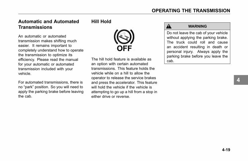
OPERATING THE TRANSMISSION
Automatic and AutomatedTransmissions
An automatic or automatedtransmission makes shifting mucheasier. It remains important tocompletely understand how to operatethe transmission to optimize itsefficiency. Please read the manualfor your automatic or automatedtransmission included with yourvehicle.
For automated transmissions, there isno “park” position. So you will need toapply the parking brake before leavingthe cab.
Hill Hold
The hill hold feature is available asan option with certain automatedtransmissions. This feature holds thevehicle while on a hill to allow theoperator to release the service brakesand press the accelerator. This featurewill hold the vehicle if the vehicle isattempting to go up a hill from a stop ineither drive or reverse.
WARNING
Do not leave the cab of your vehiclewithout applying the parking brake.The truck could roll and causean accident resulting in death orpersonal injury. Always apply theparking brake before you leave thecab.
4-19
4
OPERATING THE TRANSMISSION
WARNING
If your vehicle has an automatedtransmission, be aware that it canroll backwards when stopped ona hill or grade, or when startingfrom a stop on a hill or grade.Failure to comply may result indeath, personal injury, equipmentor property damage. Observe thefollowing guidelines:
• When stopped on a hill or grade,press the brake pedal.
• When starting from a stop on ahill or grade, quickly remove yourfoot from the brake pedal andfirmly press on the acceleratorpedal.
Auxiliary Transmission
If you have an auxiliary transmission,see your transmission manufacturer’smanual for its proper operation.
More Transmission TipsRiding the Clutch
The clutch is not a footrest. Do notdrive with your foot resting on theclutch pedal. It will allow your clutch toslip, causing excessive heat and wear,damage could result.
Release Bearing Wear
When you must idle your engine for anyperiod of time, shift your transmissionto neutral and disengage the clutch(take your foot OFF of the pedal). Thishelps prevent unnecessary wear toyour clutch release bearing, and it isless tiring for you, too.
Tips
• Always use the clutch whenmaking upshifts or downshifts.
• Always select a starting gearthat will provide sufficient gearreduction for the load and terrain.
4-20
4
OPERATING THE TRANSMISSION
• Never downshift when the vehicleis moving too fast.
• Never slam or jerk the shift leverto complete gear engagement.
• Never coast with the transmissionin neutral and the clutchdisengaged.
• To provide smooth gearengagements while shifting,use proper coordination betweenshift lever and clutch.
Double clutching is a very effectivemeans to increase the service life ofyour transmission. Double clutchingrefers to a technique where the clutchpedal is used twice per shift instead ofonce. It also requires that you adjustthe engine rpm in the middle of theshift which ultimately synchronizes thegears during shifting. Synchronizingreduces wear on the gears.
4-21
4

OPERATING THE BRAKE SYSTEM
OPERATING THEBRAKE SYSTEM
Introduction
This vehicle’s brake system functionswith the use of compressed airgenerated from the engine’s aircompressor. The compressed air isstored in various air tanks to ensurethat air pressure is available wheneverthe driver needs it.
Compressed air is delivered to thebrake system through the valve atthe brake pedal and is controlledwith various valves and brakingcircuits. The brake system is designedwith separate front, rear and (whenapplicable) trailer circuits so that if onecircuit is compromised and loses air,the other circuits will not be affected.Safety valves in each circuit will protectthe other circuits in the event that acircuit loses air.
The air compressor on the engine willtypically provide 100-130 psi (690-896kPa) to the air tanks. The vehicleis also designed with an air dryer,which removes moisture from thecompressed air in order to protect allcomponents in the air system.
The brake system may be furtherenhanced by additional devicessuch as brake proportioning valves,Anti-lock braking systems or sensorsdesigned to let you know if your brakepads need to be serviced.
Certain conditions may result in thebrake surfaces getting wet. Brakesurfaces that are wet do not performas well as when they are dry. Theremay be situations where wet brakesurfaces cannot be avoided. In suchsituations, apply the brakes while inmotion, to dry the brake surfaces.
Certain conditions may result in yourbrake surfaces becoming overheated(above 800° F or 427° C). Overheatedbrakes will damage linings anddrum surfaces, ultimately decreasingbraking performance. Refer toRetarders and Descending a grade toavoid overheating the brakes.
This vehicle may be equipped withan anti-lock braking system (ABS).This ABS reduces the possibility ofwheel lock-up. If a wheel is aboutto lock during braking, the ABS willautomatically adjust air pressure to thebrake chambers on the appropriatewheel(s) to prevent wheel lock-up. TheABS is automatically turned on whenthe ignition switch is turned on.
4-22
4
OPERATING THE BRAKE SYSTEM
WARNING
The Anti-Lock Brake System is acritical vehicle safety system. Forthe safety of you and others aroundyou, have the vehicle submitted forperiodic preventive maintenancechecks as well as having anysuspected problems immediatelychecked by an authorized dealer.Failure to properly maintain yourbrake system can lead to seriousaccidents. Failure to comply mayresult in death, personal injury,equipment or property damage.
WARNING
Do not drive through water deepenough to wet brake components,as it may cause the brakes to workless efficiently than normal. Thevehicle's stopping distance maybe longer than expected, and thevehicle may pull to the left or rightwhen brakes are applied, whichcould contribute to an accidentinvolving death or personal injury.
WARNING
Do not rely on an anti-lockbrake system that is functioningimproperly. You could lose controlof the vehicle resulting in a severeaccident, causing death or personalinjury. If your ABS lamp goeson while you are driving or stayson after the self-check, youranti-lock system might not beworking. The ABS may not functionin an emergency. You will stillhave conventional brakes, butnot anti-lock brakes. If the lampindicates a problem, have the ABSchecked.
Vehicles without anti-lock brakesystems (ABS) are typically equippedwith a bobtail brake proportioningsystem. When a trailer is notconnected, the drive axle brakeapplication pressure will automaticallybe limited by the proportioning system.
4-23
4

OPERATING THE BRAKE SYSTEM
When driven in a bobtail mode,these tractors will require greaterbrake pedal application to provide theequivalent braking to a bobtail tractornot equipped with a proportioningsystem.
Trailer ABSPower Line Communication(PLC)
North American on-highway vehiclesare equipped with a separate electricalcircuit to power the anti-lock brakesystem (ABS) on towed vehicle(s).In most cases, the ABS power willbe supplied through the Auxiliarycircuit on the primary 7-way trailerlight line connector. If the vehiclewas manufactured with a switchableAuxiliary circuit for trailer accessories,an additional 7-way connector wouldhave been provided for trailer ABSpower. In either case, the ABSpower line on the vehicle will be PLCequipped.
CAUTIONDo not splice into the non-switchableAuxiliary circuit on the primary 7-waytrailer light line. Doing so may causethe trailer ABS to malfunction. Thiscircuit is dedicated for trailer ABSpower. To add a switchable auxiliarycircuit, contact a dealership.
Vehicles and trailers built after3/1/01 must be able to turn on anIn-Cab Trailer ABS Warning Lamp(per Federal Motor Vehicle SafetyStandards (FMVSS) 121). The industrychose Power Line Communication(PLC) as the standard method to turnit on.
NOTETrailers not equipped with PLC cannot turn on the In-Cab Trailer ABSWarning Lamp.
4-24
4
OPERATING THE BRAKE SYSTEM
NOTEFor doubles or triples, the lamp doesnot distinguish between trailers. AnABS problem in any of the trailerswill activate the Trailer ABSWarningLamp.
NOTEIf you change the intended servicein any way (i.e. number of axles,multiple trailers, add switchabletrailer accessories, etc.) from thedate the vehicle was manufactured,you should contact your trailermanufacturer and/or trailer anti-lockbrake manufacturer to determine ifthe power available at the 7-waytrailer light line is adequate. Failureto do so might result in insufficientpower to the trailer ABS systemwhich may affect its operation.
CAUTION
The center pin of the 7-way trailerlight line may be constantly poweredfor ABS. Make sure it will notaccidently turn on trailer equipment.
Special Trailer ABS (WithoutPLC) Option
If a trailer does not have PLC, butit does have ABS that is poweredthrough an optional second trailerconnector (ISO 3731) and that trailerABS is designed to control the TrailerABS Warning Lamp in the cab andthe vehicle has been ordered with theoption to turn on this lamp for thesetypes of trailers, then this lamp will turnon when that trailer ABS has a systemproblem. This should be checked by adealer as soon as possible. The TrailerABS Warning Lamp will not turn on forthe power-on test when connected tothese types of trailers.
NOTEVery few trailers built before 3/1/01have this option. Trailers built after3/1/01 are built with PLC technology.
4-25
4

OPERATING THE BRAKE SYSTEM
Advanced ABS with StabilityControl
This vehicle may be equippedwith an optional Electronic StabilityProgram (ESP). ESP is a feature forABS-equipped vehicles that reducesthe risk of rollovers, jackknifing andother loss of control situations. ESPfeatures include Roll Stability Program(RSP) and Yaw Control.
During operation, the ECU of theBendix® Advanced ABS systemconstantly compares performancemodels to the vehicle’s actualmovement, using the wheel speedsensors of the ABS system, as wellas lateral, yaw, and steering anglesensors. If the vehicle shows atendency to leave an appropriate travelpath, or if critical threshold values areapproached, the system will interveneto assist the driver.
Roll Stability Program
Bendix® RSP, an element of theoverall ESP system, addressesrollover conditions. In the case ofa potential roll event, the ECU willoverride the throttle and quickly applybrake pressure at all wheel ends toslow the vehicle combination. Thelevel of braking application during anRSP event will be proportional to rollrisk.
A Real World Example of Howthe RSP System Operates
Excessive speed for road conditionscreates forces that exceed thethreshold at which a vehicle is likely torollover on a higher-friction surface.
The system automatically reducesengine torque and applies the servicebrakes (based on the projected rolloverrisk) to reduce the vehicle speed,
thereby reducing the tendency to rollover.
RSP Example
4-26
4

OPERATING THE BRAKE SYSTEM
Yaw Stability
Yaw stability counteracts the tendencyof a vehicle to spin about its verticalaxis. During operation, if the frictionbetween the road surface and the tiresis not sufficient to oppose lateral (side)forces, one or more of the tires canslide, causing the truck/tractor to spin.
These yaw events are referred to aseither “under-steer” (where there is alack of vehicle response to steeringinput due to tire slide on the steer axle)or “over-steer” (where the tractor'srear end slides out due to tire slideon the rear axle) situation. Generally,shorter wheelbase vehicles (tractors,for instance) have less natural yawstability, while longer wheelbasevehicles (straight trucks, for instance)have greater natural yaw stability.Factors that influence yaw stabilityare: wheelbase, suspension, steeringgeometry, weight distribution front torear, and vehicle track width.
Yaw Control
Yaw Control responds to a widerange of low- to high-friction surfacescenarios including rollover, jackknifeand loss of control. In the case ofvehicle slide (over-steer or understeersituations), the system will reduce thethrottle and then brake one or moreof the “four corners” of the vehicle(in addition to potentially applyingthe trailer brakes), thus applying acounter-force to better align the vehiclewith an appropriate path of travel. Forexample, in an over-steer situation,the system applies the “outside”front brake; while in an under-steercondition, the “inside” rear brake isapplied.
A Real World Example of HowYaw Control Operates
Excessive speed exceeds thethreshold, creating a situation where avehicle is likely to spin and jackknife.
The Bendix® Yaw Control systemreduces engine throttle and selectivelyapplies brakes to reduce the vehiclespeed, thereby reducing the tendencyto jackknife.
Yaw Control Example
4-27
4
OPERATING THE BRAKE SYSTEM
ESP May Reduce TheVehicle Speed Automatically
To minimize unexpected decelerationand reduce the risk of a collision theoperator must:
• Avoid aggressive drivingmaneuvers, such as sharpturns or abrupt lane changes athigh speeds, which might triggerthe stability system.
• Always operate the vehicle safely,drive defensively, anticipateobstacles and pay attentionto road, weather and trafficconditions. ABS, ATC and ESPstability systems are no substitutefor prudent, careful driving.
Towing Doubles OrTriples May Reduce TheEffectiveness Of StabilitySystems
ESP is designed and optimized fortrucks and for tractors that tow singletrailers. If a tractor equipped withESP is used to power multiple trailercombinations (known as “doubles” or“triples”) the effectiveness of the ESPsystem may be greatly reduced.
WARNING
Exercise extreme care when towingdoubles or triples with a vehicleequipped with Electronic StabilityProgram. Excessive speed andaggressive maneuvers, such assharp turns, sudden steering inputsor abrupt lane changes should beavoided because these maneuverscould cause loss of vehicle controlpossibly resulting in an accidentinvolving death or personal injury.
Limitations Of StabilitySystems
The ESP stability system’seffectiveness may be greatly reducedif:
• The load shifts due to improperretention, accident damage or theinherently mobile nature of someloads (for example, hanging meat,live animals or partially ladentankers),
• The vehicle has an unusually highor off-set center of gravity (CG),
• One side of the vehicle drops offthe pavement at an angle that istoo large to be counteracted by areduction in speed,
• The vehicle is used to haul doubleor triple trailer combinations,
• If very rapidly winding steeringinputs are inputted at high speeds,
4-28
4

OPERATING THE BRAKE SYSTEM
• There are mechanical problemswith suspension leveling of thetractor or trailer resulting in unevenloads,
• The vehicle is maneuvering on ahigh banked road creating eitheradditional side forces due to theweight (mass) of the vehicle ora deviation between expected &actual yaw rates,
• Gusty winds are strong enoughto cause significant side forceson the vehicle and any towedvehicles.
To Maximize TheEffectiveness Of ESP• Loads must be properly secured
and evenly distributed at all times.
• Drivers need to exercise extremecaution at all times, and avoidsharp turns, sudden steeringinputs or abrupt lane changes athigh speeds, particularly if:
a. the vehicle hauls loads thatcould shift,
b. the vehicle or load has a highor off-set center of gravity(CG) when loaded, or
c. the vehicle tows doubles ortriples.
Truck Chassis Modifications
The ESP system was specificallycalibrated and validated only foryour vehicle’s original factory-builtconfiguration. If your vehicle’s chassiscomponents are altered (for example;a wheelbase extension or reduction,tag axle addition or removal, tractor totruck conversion or steering systemcomponent change) the ESP systemmust be disabled immediately by aqualified mechanic.
WARNING
Failure to disable ESP “ElectronicStability Program” when modifyinga vehicle could result in a loss ofvehicle control possibly resultingin an accident involving death orpersonal injury.
4-29
4

OPERATING THE BRAKE SYSTEM
WARNING
For vehicles equipped with ESP“Electronic Stability Program” do notreplace the vehicle’s steering wheelwith an aftermarket or different partnumber than originally supplied.Using a different steering wheelcould cause ESP to malfunctioncausing a loss of vehicle controlpossibly resulting in an accidentinvolving death or personal injury.
Steering Angle SensorRe-Calibration
Whenever maintenance or repairwork is performed to the steeringmechanism, linkage, gear, adjustmentof the wheel track, or if the steeringangle sensor is replaced or the steeringwheel is changed or re-centered, theSteering Angle Sensor must bere-calibrated.
WARNING
If the Steering Angle Sensor isnot re-calibrated, the Yaw Controlsystem will not function properly. Auncalibrated sensor could result in aloss of control of your vehicle whichcan lead to an accident involvingdeath or personal injury.
Wheel Spin Control WarningLamp
Your truck/tractor ABS may have anacceleration slip regulation (ASR)or automatic traction control (ATC)feature. This feature is controlled by aswitch as shown in the next illustration.Either of these features is monitored bya warning lamp located on the switch.
The Traction Control warning lamp onpage 3-37 will briefly illuminate andthen go out when the ignition switchis first turned on. The traction controlwarning lamp will illuminate wheneverthe ASR or ATC system detects drivewheel spin. The lamp will remainilluminated as long as wheel spin isdetected and the ASR or ATC system
4-30
4

OPERATING THE BRAKE SYSTEM
is applying the drive wheel brakes orreducing engine torque. Do not allowthe traction control lamp to remain oncontinuously for an extended length oftime. Extended continuous use of theASR/ATC can cause overheating ofthe drive wheel brakes. Engine torqueor vehicle speed should be reducedto eliminate wheel spin and preventexcessive application of the ASR/ATCsystem. Except for checking for properillumination of the ABS and tractioncontrol warning lamps when firststarting the vehicle, and for monitoringthese lamps while driving, no specialoperating procedures are required.For detailed system description, seeliterature for your specific ABS thatwas provided with your vehicle.
Optional ATC FunctionsWheel Spin Control (option)
Your ABS may have the optionalAcceleration Slip Regulation(ASR)/Automatic Traction Control(ATC) feature. This feature ismonitored by a wheel spin control ASRWarning Lamp. See the appropriatevehicle section in this manual fordetails. This feature helps improvetraction when vehicles are on slipperysurfaces or surfaces with poor traction(i.e. mud or snow) by reducing drivewheel overspin. Wheel spin controlworks automatically in two differentways:
• If a drive wheel starts to spin,wheel spin control applies airpressure to brake the wheel. Thistransfers engine torque to thewheels with better traction.
• If all drive wheels spin, wheel spincontrol reduces engine torque toprovide improved traction.
Wheel spin control turns itself on andoff, you do not have to select thisfeature. If drive wheels spin duringacceleration, the ASR Warning Lampcomes on, indicating wheel spin controlis active.
Do not allow the ASR Warning Lampto remain on continuously for anextended length of time. Extended,continuous use of the ASR/ATC cancause overheating of the drive wheelbrakes.
Deep Snow and Mud Switch(option)
A deep snow and mud switch isincluded with Wheel Spin Control. TheDeep Snow and Mud feature is helpfulduring acceleration. This functionincreases available traction on extrasoft surfaces like snow, mud or gravel,by slightly increasing the permissiblewheel spin. When this function is in
4-31
4

OPERATING THE BRAKE SYSTEM
use, the ASR Warning Lamp blinkscontinuously.
Off-Road ABS Function Switch(option)
Your vehicle may be equipped witha separate switch to activate anOff-Road ABS function. This functionis NOT to be used for On-Highwaydriving but is intended to be usedto improve stopping performance inOff-Highway conditions (e.g. loosegravel and mud). The Off-Road ABSfunction is accomplished by allowing a“wedge” of material to build-up in frontof momentarily locked wheels.
Features and Benefits
• Changes the ABS control limits toallow for a more aggressive ABSfunction while off-road.
• Improves vehicle control andhelps reduce stopping distancesin off-road conditions or on poor
traction surfaces such as loosegravel, sand and dirt.
• Allows retarders to functionindependently of the ABS function.
• If your vehicle does not have anengine retarder, the Off- RoadABS switch will function the same.
CAUTIONNever drive your vehicle onimproved roads/highways with theOff-Road ABS function turned on.When you drive your vehicle onto animproved road surface or highway,immediately turn off the Off-RoadABS switch. Failure to do sowill cause the ABS system to notfunction properly in an ABS eventunder 25 mph and could result in anaccident or personal injury.
WARNING
While the off-road mode canimprove vehicle control andshorten stopping distances, somesteering ability may be reducedon certain surfaces resulting fromthe momentarily sliding tires.Always operate your vehicle at safeoperating speeds. Failure to do somay cause you to lose control ofthe vehicle and could result in anaccident or personal injury.
How The Off-Road ABSFunction Works
• The ABS lamp flashes slowlyduring off-road mode engagement.This is done to alert you of amodification to the ABS controlsoftware.
• At speeds above 25 mph, the ABScontroller operates in the normalon-highway mode.
4-32
4

OPERATING THE BRAKE SYSTEM
• At speeds between 10 and 25mph, the ABS control software ismodified to allow short periods(0.25 seconds) of locked-wheelcycles.
• At speeds below 10 mph, the ABScontrol software is turned off toallow locked wheels.
• When the Off-Road ABS functionis enabled, the Retarder Disableoutput is turned off. That is,the engine retarders are left tofunction without ABS intervention.For additional information, see theOff-Road ABS pamphlet in yourvehicle’s glove box.
Retarders
Various retarders are available whichfunction against the engine, driveline,or transmission. These are devicesthat use your engine’s power to slowdown your vehicle. They save wearand tear on your service brakes andcan be a safety feature, too, becausethey can keep your brakes fromoverheating.
Ideally, you should always slow yourvehicle with your retarder (wherepermitted by law) and use your servicebrakes only for stopping completely.Operating this way will greatly prolongthe life of your brakes.
WARNING
Do not use any of the vehicle’sretarders in any situation thatrequires an immediate stop and/orin situations of poor traction (suchas wet, icy or snow covered roads).Trying to use the retarder insteadof the service brakes may cause aloss of vehicle control which mayresult in an accident involving deathor personal injury.
WARNING
The service brakes must be usedin an emergency. The retarderalone might not stop you fastenough to prevent an accident.Failure to comply may result indeath, personal injury, equipment orproperty damage.
The retarder is NOT intended as theprimary brake for the vehicle, nor isit an emergency brake. The retarder
4-33
4

OPERATING THE BRAKE SYSTEM
only helps the service brakes by usingpressure to slow the drivetrain. Usethe service brakes for quick stops.
Do not use the retarder when operatingon road surfaces with poor traction(such as wet, icy, or snow coveredroads or gravel). Retarders cancause the wheels to skid on a slipperysurface.
Driving Bobtail or with anUnloaded Trailer
We recommend that you do not useyour engine retarder to slow downwhen you are bobtailing or pulling anempty trailer.
WARNING
Using an engine retarder can causea wheel lockup. The trailer is notloading the tires enough to givethe traction you may need. Whenyou are bobtail or unloaded, youcan have a serious accident ifyour wheels lock suddenly duringbraking. You could be killed orinjured. Don’t use your retarderwhen you are driving bobtail or withan unloaded trailer.
Transmission Retarder
If you have this option, it will actlike a brake to slow your vehiclewithout using the brakes. Take yourfoot off the throttle and operate theretarder switch. When you do notneed full retarder effect, you canapply it intermittently (off and on)to cause gradual or partial slowing.Continuous application of your retarderwill cause your hydraulic fluid to gethotter. Intermittent application will helpprevent overheating.
4-34
4

OPERATING THE BRAKE SYSTEM
WARNING
Do not rely on your automatictransmission hydraulic retarder tostop your vehicle. If your engineshuts down, the vehicle’s retarderwill cease to operate which may leadto an accident involving death orpersonal injury. Always be ready tosuddenly apply the service brakes.
Parking Brake
1. Normal Run Position2. Trailer Park With Vehicle
Released3. System Park or Trailer
Charge With Vehicle Parked
Parking brakes work in reverse actionof the regular brakes. When theparking brakes are engaged, air isexhausted from the spring chamberswhich allow the spring to engage thebrakes. This design also provides forthe safety function if a brake circuithas a leak and loses air. In such ascenario, the parking brakes will apply.
The vehicle’s parking brake controlsare the yellow diamond shaped knobon your dash board. If the vehicle isequipped to tow a trailer, then there willbe an additional red octagon shapedknob for the trailer parking brakes.Parking brakes will be engaged wheneither of these knobs are pulled OUT.(If one knob is pulled out, the otherknob will automatically pop out.)
Pushing IN a knob will disengagethe respective parking brakes. If youpush in the yellow knob only, youwill disengage the vehicle’s parking
4-35
4

OPERATING THE BRAKE SYSTEM
brakes but will not disengage the trailerparking brakes (if applicable). Eitherknob will pop back out if the systempressure is not above 60 psi (414 kPa).
The instrument panel display willprovide a message any time theparking brakes (vehicle or the trailer)are set and the vehicle is put intomotion.
4-36
4

CRUISE CONTROL
CRUISE CONTROL
Cruise Control Switch
This vehicle may have cruise controlswitches located on the steering wheelinstead of the switches on the dashboard. The instructions are still thesame. Please see Steering WheelControls on page 3-72 to determinewhere the cruise control switches arelocated.
For information about the AdaptiveCruise Control, see Adaptive CruiseControl on page 4-39.
• To Turn On:
Press the ON/OFF button.
• To Turn Off:
Press the ON/OFF button. Anyprevious speed settings are cleared.
Using Cruise Control While Driving
Setting Cruise Speed
1. Ensure that the vehicle speedis above the minimum cruisecontrol speed (19 mph (30 km/h)for PACCAR MX engine and 30mph (48 km/h) for the Cumminsengines) and the engine speed isabove 1100 rpm.
2. Press the "ON/OFF" button.
3. Accelerate the vehicle to thedesired cruise speed.
4. Press the "SET" button to set thecruise speed.
NOTECruise Control may not hold the setspeed going down hills. If the speedincreases going down a hill, usethe brakes to slow down. This willcancel Cruise Control.
Changing the Cruise Set Speed
For vehicles with cruise control buttonson the steering wheel, the cruisespeed may be changed by using the+/- button. The pressing and holdingthe + button will increase speed whilepressing and holding the - button willdecrease speed. For vehicles withdash mounted cruise control switches,changing the speed is done throughthe "Set/Resume" button. To increasethe speed, press and hold the Setbutton. To decrease the speed, pressand hold the "Resume" button.
Cancelling Cruise Control
You can cancel cruise control in anyof these ways:
• Tap the brake pedal.
• Tap the clutch pedal.
4-37
4

CRUISE CONTROL
• Press the ON/OFF button if thevehicle has dash board mountedcruise control switches or theCANCEL button if the vehicle hascruise control switches on thesteering wheel.
Resuming Cruise Control
1. If you tapped the brake orclutch pedal, the cruise controlremembered the previously setcruise speed. To resume thatset speed, accelerate above theminimum cruise control speed andpress the "RESUME" button.
2. If you pressed the "OFF" button(or the steering wheel mounted"CANCEL" button) or turned theignition key OFF, this cleared thesystem memory and you will needto set a new cruise speed.
Using Cruise Control for StationaryPTO Operation
Setting Idle Speed
1. Ensure parking brakes are applied.
2. Ensure transmission is in Neutral.
3. Engage PTO per themanufacturer's operatinginstructions.
4. Press the "ON" button.
5. Press the "SET" button to obtainthe desired engine rpm.
Cancelling Cruise Control
You can cancel cruise control in anyof these ways:
• Tap the brake pedal.
• Tap the clutch pedal.
• Press the "OFF" button (orthe steering wheel mounted"CANCEL" button).
NOTECruise control functions andfeatures may vary depending uponwhich engine you have. For specificexplanation of your cruise control,see the cruise control or enginemanual included with your vehicle.
This vehicles electronic system willperform a ‘rationality check’ every timethe vehicle is started. This check isto ensure that the service brakes areworking before allowing cruise controlto function. This safety feature isdesigned to ensure that a driver is ableto cancel the cruise set speed by usingthe service brake pedal. The systemwill not allow cruise control operation ifit does not pass the ‘rationality check’.The instrument cluster will prompt youto press the service brake pedal if ithas not been pressed since the vehiclehas been started.
4-38
4
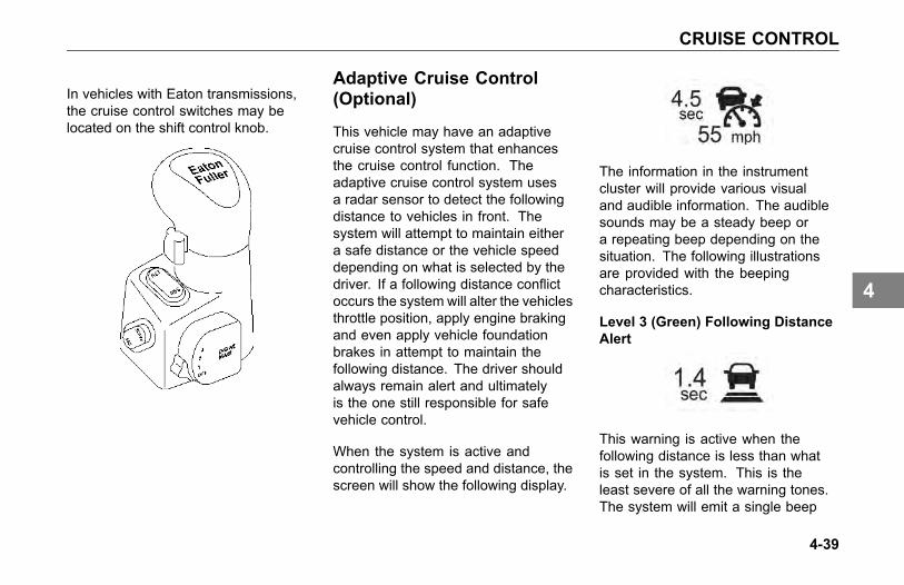
CRUISE CONTROL
In vehicles with Eaton transmissions,the cruise control switches may belocated on the shift control knob.
Adaptive Cruise Control(Optional)
This vehicle may have an adaptivecruise control system that enhancesthe cruise control function. Theadaptive cruise control system usesa radar sensor to detect the followingdistance to vehicles in front. Thesystem will attempt to maintain eithera safe distance or the vehicle speeddepending on what is selected by thedriver. If a following distance conflictoccurs the system will alter the vehiclesthrottle position, apply engine brakingand even apply vehicle foundationbrakes in attempt to maintain thefollowing distance. The driver shouldalways remain alert and ultimatelyis the one still responsible for safevehicle control.
When the system is active andcontrolling the speed and distance, thescreen will show the following display.
The information in the instrumentcluster will provide various visualand audible information. The audiblesounds may be a steady beep ora repeating beep depending on thesituation. The following illustrationsare provided with the beepingcharacteristics.
Level 3 (Green) Following DistanceAlert
This warning is active when thefollowing distance is less than whatis set in the system. This is theleast severe of all the warning tones.The system will emit a single beep
4-39
4

CRUISE CONTROL
repeating at a rate of 42 tones perminute.
Level 2 (Amber) Following DistanceAlert
This warning is active when thefollowing distance is less than what isset in the system. This warning is moresevere than the Level 3 FollowingDistance Alert. The system will emit adouble beep repeating at a rate of 80tones per minute (40 double beeps perminute).
Level 1 (Red) Following DistanceAlert
This warning is active when thefollowing distance is less than whatis set in the system. This warningtone is the most severe followingdistance alert. The system will emita continuous beep repeating at arate of 188 tones per minute and apopup “WARNING Following Distance”:Increase Gap to Vehicle Ahead”.
Brake Command Warning
This is the most severe warning issued.When the system uses the foundationbrakes the level 1 warning will appearon the screen accompanied with a"Collision Alert BRAKE" message.The warning is active when the drivermust take immediate evasive action by
applying more braking power and/orsteering clear of the vehicle ahead toavoid a potential collision. The systemwill emit a solid beep for a 3 secondduration.
Stationary Object Alert
The system can also detect stationaryobjects in the vehicles path. Theoperator needs to take control of thevehicle to avoid the stationary object.The icon will be accompanied with apop-up message but no audible sound.
4-40
4

CRUISE CONTROL
WARNING
The Wingman® ACB sensor maynot be able to detect vehicles andobjects with limited metal surfaces(such as recreational vehicles,horse-drawn buggies, motorcycles,logging trailers, etc.). Failure tounderstand the system limitationmay result in death, serious injury,and/or property damage.
Fault Alert
This warning is presented to alertthe operator that the ACB system ismalfunctioning and will be disabled.The operator will need to resumecontrol of the vehicle’s throttle and
brakes. The system will remaindisabled until the fault is corrected.
4-41
4

AXLE
AXLE
Differential Lock
The vehicle may be equipped withswitches to lock the either of the rearaxle differentials. Depending on howthe vehicle is specified, a combinationindividual switches may be availablethat can lock the interaxle drivelineand/or any combination of the forwardrear or rear-rear driving axles.
The interaxle differential switch allowseach axle to turn independently.In certain situations, engaging theinteraxle differential lock relievesstress on the rear axles and reducestire wear. Engaging this switch willalso provide better traction in slipperyor loose gravel conditions.
In the LOCK position, continuousoperation on paved, dry surfaces, putstress on the axles, and can possiblydamage the internal gears. The switchhas a guard to prevent accidentaloperation of the switch.
Locking the differentials is typicallyused during ice or snow conditionsand without tire chains, unpaved roadsthat have loose sand, mud or unevensurfaces. Look ahead and predictwhen the differential needs to belocked. Stop the vehicle and lock thedifferentials before approaching.
While using the differential in thelocked position, do not exceed 25 mph(40 km/h). When disengaging thedifferential lock, reduce the throttle toprevent drivetrain damage.
WARNING
Do not put the differential lock in theLOCK position while the wheels arespinning freely (slipping), you couldlose control of the vehicle or causeaxle damage. Switch to LOCK onlywhen the wheels are not spinning.Failure to comply may result indeath, personal injury, equipment orproperty damage.
4-42
4

AXLE
Dual Range (Two-Speed)Rear Axle
Your vehicle may be equipped with atwo-speed or dual range axle (option).You can select two rear axle ratios foroperating under heavy loads or roughterrain as well as for over the roadhauling.
The Low Range provides maximumtorque for hauling heavy loads ortraveling over rough terrain. The HighRange is a faster ratio for highwayspeeds and general over the roadconditions. A switch on the accessoryswitch panel controls the Dual RangeRear Axle. You will notice that theswitch has a guard to protect you fromactivating it accidentally. Always parkyour vehicle with the range selector inLOW.
Dual Range Axle Operation
Important tips on operating a DualRange Axle with Interaxle Differential:
Shift the axle with the inter-axledifferential in the unlocked positiononly.
When you are driving with poortraction, lock the differential. Whenyou have the differential locked, drivewith the axle in LOW range only.
When you are driving on a surfacewith good traction, keep the interaxledifferential unlocked. You can drivewith the axle in the LOW or HIGHrange.
Always UNLOCK the inter-axledifferential before shifting the axlespeed range.
CAUTION
If you shift the axle range with theinter-axle differential in LOCK, youcould seriously damage the axles.Never shift the axle range with thedifferential locked.
4-43
4

AXLE
Starting-Up1. Unlock the inter-axle differential
before starting.
2. Put the Range Selector in theLOW range. Shift the transmissionto start the vehicle moving.
3. When you are driving on roughterrain and secondary roads, orunder a very heavy load, keep theaxle in the LOW range. Shift thetransmission to maintain properroad speed.
WARNING
Never shift the axle when movingdownhill. Engine drivelinedisengagement may occur,eliminating engine retardation andallowing the wheels to spin fasterthan the current speed of the engine.This may require severe braking toslow the vehicle down and can resultin an accident. Failure to complymay result in death, personal injury,equipment or property damage.
Proper shifting of the axle depends onthe synchronization of engine/drivelineand wheel speed. When you shiftthe axle, the connection between theengine and wheels is momentarilydisengaged while the gearing issynchronized. Normally when the axleis shifted the speed of the engine, axle,and wheels adjust, allowing for propergear engagement.
When going downhill the wheels willnot slow down, but will tend to speedup, which makes gear synchronizationalmost impossible. As a result, theaxle is neither in HIGH nor LOW rangeand all engine/driveline retardation islost. Without engine retardation it ismore difficult to slow the vehicle downand greater stress is put on the brakesystem.
CAUTION
To avoid damaging your vehicle shiftthe axle at slower travel speeds untilyou are used to driving with a dualrange axle.
4-44
4

AXLE
LOW to HIGH (Cruising)
When you go from rough terrain tohighway driving, shift the axle to theHIGH range following this procedure:
1. Be sure the differential isUNLOCKED.
2. Maintain your vehicle speed(accelerator depressed) and movethe Range Selector lever to HIGH.
3. Keep driving with the acceleratordepressed until you want the axleto shift.
4. To make the axle shift, release theaccelerator until the axle shifts.You are now in the HIGH axlerange for highway speeds. Shiftthe transmission normally to reachyour desired cruising speed.
HIGH to LOW (RoughTerrain)
If you need to downshift the axle formore power or you are driving onrough terrain:
1. Maintain your vehicle speed(accelerator depressed) and movethe Range Selector lever to LOW.
2. Keep driving with the acceleratordepressed until you want the axleto downshift.
3. To make the axle downshift,release and depress theaccelerator quickly to increase theengine RPM. The axle will shift toLOW range.
4. You are now in the LOW axlerange for rough terrain and heavyloads. Shift the transmissionnormally to maintain the desiredspeed.
Auxiliary Axles - Pusher orTag
Adjustable auxiliary axles (commonlyknown as Pusher or Tag axles) canadd to the productivity of the vehicle byincreasing the load capabilities of thevehicle when they are in the deployed(down) position. There are differentconfigurations of axles with differentfunctionality (liftable versus steerable)Without the extra axle, the excessiveweight can reduce the service lifeof vehicle components such as, butnot limited to, the frame rail, axles,suspension and brakes.
Operation of the auxiliary axlesincludes the proper maintenance of thesystem and calibration of its controls.Operating the auxiliary axles will alsorequire a firm understanding of the
4-45
4

AXLE
GAWR and the load that is beingcarried.
The vehicle will have switches on thedash to control the position of theauxiliary axles. In certain situations,however, the system will override thecontrols to protect the axle system.Any liftable and steerable auxiliaryaxles will rise off of the ground whenthe parking brakes are engaged orwhen the vehicle is put in reverse.If the liftable auxiliary axle is not asteerable axle, then it will remain in thedown position when activated by thedash mounted switch.
Operating the auxiliary liftable axlesmust be performed in a manner thatdoes not exceed the axle creep rating.Axle creep ratings are weight andspeed limits that are allowed whilethe vehicle is fully loaded (in excessof the vehicle’s standard GAWR) andthe axle is in its up position. Axlecreep ratings are assigned by the
axle manufacturer and are based onaxle model and intended service ofthe vehicle. Contact an authorizeddealership if you are unable to identifythe axle creep rating of this vehicle.
• Liftable/steerable (axle liftcalibration required)
• Liftable/non-steerable (axle liftcalibration required)
• Non-liftable (some suspensionsrequire dump valve calibration)
WARNING
Do not operate or park thevehicle with auxiliary axles inthe down/loaded position whenvehicle is unladen, or is beingunloaded. Raise or dump air intodriver-controlled auxiliary axle(s)prior to unloading vehicle. Failureto do so can result in loss of vehiclecontrol or rollaway that may result indeath, personal injury, equipment orproperty damage.
4-46
4
AXLE
Axle Creep Rating DefinitionCreep Ratings
Low speed, off-highway (work site)axle loads, which exceed the standardgross axle weight rating (GAWR) of aparticular axle.
Operator's using vehicles equippedwith liftable auxiliary axles mustconsider creep ratings when anyliftable axle is unloaded or in the raisedposition. Liftable auxiliary axles shouldonly be raised (or unloaded) to improvemaneuverability in an off-road use orwhen vehicle is unloaded.
NOTEAxle Creep ratings MUST NOT beexceeded.
Contact your dealer or axlemanufacturer to determine whatthe creep rating is for your particularaxle(s) and configuration. Creep
ratings are generally limited to thefollowing:
• Tandem rear axles only
• Straight trucks only
• Maximum spring mountcenters per axle manufacturersspecifications
• Maximum tire static loaded radius(SLR) per axle manufacturersspecifications
CAUTIONAlways lower the axles as soonas possible after receiving a load.Never exceed 5 miles per hour whendriving with a load with the auxiliaryaxle(s) raised/unloaded. Failure tolower the axle(s) can overload theframe and remaining axles, andcould cause equipment damage.
WARNING
Never operate the vehicle withmore pressure in the lift axles thanis necessary to carry the load,as determined by the calibrationprocedure described. Failure to doso can result in loss of traction andstability at the steer and/or driveaxles and can result in increasedbraking distance which could causeloss of vehicle control resulting inan accident. Failure to complymay result in death, personal injury,equipment or property damage.
CAUTION
Do not modify the air system and/orcontrol functionality on a factoryinstalled auxiliary axle(s). Modifyingthe factory operation of the pusherand/or tag axle(s) will void yourwarranty, and can cause equipmentdamage.
4-47
4

AXLE
CAUTIONA change in tire size on either theauxiliary axles or the drive/steeraxles can change the calibrationof the auxiliary axles. If tires areinstalled with a different loadedradius, the calibration proceduremust be repeated. Failure to do socan cause equipment damage.
Liftable/Steerable orLiftable/Non-SteerablePusher and/or Tag AxleCalibration Procedure
Below are some general instructionson how to adjust and calibrate the aircontrol valve for the auxiliary axles toobtain the proper load distribution ofthe axle(s). For additional operatingand maintenance instructions, see thepusher or tag suspension manufacturerliterature in the glove box or contactthem directly.
NOTEThis procedure must be performedprior to placing the vehicle intoservice.
Setting the Pressure-to-LoadRatio
To obtain the desired axle loaddistribution, you must correlate thesuspension air gauge pressure to theactual axle load by scaling the axleweight(s) and adjusting the pressureto obtain the desired load. Once thedesired load or load range is achieved,document the pressure-to-load ratio orsetting for future use.
4-48
4
AXLE
General CalibrationGuidelines
These instructions are general innature. For more specific instructions,review the pusher or tag suspensionmanufacturers maintenance manual orcontact the nearest authorized dealer.
NOTEPerform this procedure at or neara weight scale. Procedure canbe performed while parked on theweight scale if scale is available.
1. Park loaded vehicle on levelsurface with wheels blocked.
2. Release vehicles springbrakes. (Do not release forLiftable/Non-Steerable pusher ortag axles).
3. Lower the pusher/tag axles withthe axle lift control flip valve. (For
some non-liftable axles, inflate airsuspension).
4. Adjust the amount of load oneach axle by turning the pressureregulator clockwise to increasethe load or counterclockwiseto decrease the load. (Thesuspension manufacturermay publish pre-establishedPressure-to-Load Ratio PressureSettings to assist you in achievingan estimated ground load).
5. After setting the pressure to obtainthe desired axle load, verify properground loading with the weightscale.
NOTEExceeding local, state or federalweight limits may result in citations.Contact your local commercialweight enforcement office for limitsin your area.
Operation guidelines
NOTESteerable-pusher and/or tag axle(s)will raise when the transmission isshifted into reverse or when theparking brakes are applied.
4-49
4

AXLE
Maximizing Drive AxleTraction
Adjust the pressure regulator controlknob to a lower pressure until desiredtraction is obtained. By reducing airpressure at pusher or tag axle, loadwill be transferred to drive axles. Donot overload drive axles.
Coupling To A LoadedTrailer
Inflate air springs of the auxiliary axlesto the desired pressure after couplingto a loaded trailer while still maintainingproper traction of the drive axles.
Unloading Operation
Always deflate air springs of theauxiliary axles before attempting tounload vehicle. This allows maximumtraction of the drive axles to control thevehicle.
4-50
4

AXLE
Non-liftable (Non-steerable)Axles
Some suspensions require dump valvecalibration.
Example: Neway dead axles do notlift, but the air can be dumped out ofthem to unload them when empty. Airpressure is controlled via an adjustableregulator. These axles need to becalibrated for load.
Contact your authorized dealer oraxle/suspension manufacturer fordump valve calibration procedures.
4-51
4

SUSPENSION
SUSPENSION
Air Suspension Height/AirPressure
Your vehicle may have an airsuspension and a deflation switchwhich allows the air in the suspensionto be exhausted from a switch on thedash. The normal purpose of thisfeature is to allow you to lower thevehicle for loading.
A guard on the switch preventsyou from accidentally deflating thesuspension.
CAUTION
Operating a vehicle with airsuspension bags either overinflatedor under-inflated may causedamage to driveline components. Ifa vehicle must be operated undersuch conditions, do not exceed 5mph (8 km/h). Failure to complymay result in equipment damage.
Suspension Air PressureGauge
The Suspension Air Pressure gauge(option), see Optional Gauges on page3-43, which indicates the amount of airpressure in the air suspension springsin pounds per square inch (psi). Airpressure in the spring is related tothe rear axle load. The greater therear axle load, the greater the airpressure in the air bags. Therefore,the air pressure displayed will vary,depending upon the rear axle load.
4-52
4

SUSPENSION
Driving with Deflated AirSprings
If an air spring is ruptured, there willbe enough air pressure to drive thevehicle to a safe stop off the highwayto investigate the problem.
WARNING
Do not continue to drive withruptured air springs. The air losscan cause the spring brakes to applyallowing your brakes to drag andburn up the linings, which couldlead to an accident causing death orpersonal injury. Do not continue tooperate the vehicle in this condition.
You can get to a repair facility if you dothe following:
1. Remove the height control linkconnected to the axle and tothe suspension air valve controlarm. This will cause the air valve
control arm to center in the closedposition.
2. The air system can then bepumped up to normal pressure forcontinued operation.
WARNING
Do not drive the vehicle if the airpressure is less than 100 psi (690kPa). Driving the vehicle with lessthan 100 psi (690 kPa) could makethe brakes unsafe to use whichcould cause an accident involvingdeath or personal injury.
CAUTION
Operating a vehicle with airsuspension bags either overinflatedor underinflated may cause damageto driveline components. If a vehiclemust be operated under suchconditions, do not exceed 5 mph (8km/h).
4-53
4
AFTER-TREATMENT SYSTEM
AFTER-TREATMENTSYSTEM
Introduction
This vehicle will has an exhaustAfter-Treatment System (ATS), tocontrol vehicle exhaust emissions,which consist of a Diesel ParticulateFilter (DPF), Selective CatalystReduction (SCR), RegenerationSwitch and warning lights. The DPFwill trap soot from the engine exhaustgases. The SCR uses Diesel ExhaustFluid to reduce the levels of NOx inthe engine exhaust. The ATS willperiodically clean (regenerate) theDPF. Please refer to the ExhaustAftertreatment System Supplementprovided with the vehicle for moredetailed description of functionality andwarnings.
4-54
4

DRIVING TIPS AND TECHNIQUES
DRIVING TIPS ANDTECHNIQUES
Introduction
This section covers additional drivingtips and techniques on how to driveyour vehicle more efficiently.
Coasting
WARNING
Do not coast with the transmissionin neutral or with the clutch pedaldepressed - it is a dangerouspractice. Coasting in neutral mayresult in damage to your drivetrainwhen you try to re-engage thetransmission. You could lose controlof the vehicle which can lead to anaccident involving death or personalinjury.
Do not coast with the transmissionin neutral or with the clutch pedaldepressed. Besides being illegal anddangerous, coasting is also expensive.It causes premature failure or damageto the clutch and transmission andoverloads the brake system.
Coasting with the transmissionin neutral also prevents propertransmission component lubrication.During coasting the transmission isdriven by the rear wheels, and thecountershaft gear (which lubricatesthe transmission components by oilsplash) will only be turning at idlespeed.
4-55
4

DRIVING TIPS AND TECHNIQUES
Descending a Grade
WARNING
Do not hold the brake pedal downtoo long or too often while goingdown a steep or long grade. Thiscould cause the brakes to overheatand reduce their effectiveness. Asa result, the vehicle will not slowdown at the usual rate. To reducethe risk of an accident which couldcause death or personal injury,before going down a steep or longgrade, reduce speed and shift thetransmission into a lower gear tohelp control your vehicle speed.Failure to follow procedures forproper downhill operation couldresult in loss of vehicle control.
Engine Overspeed
CAUTIONTo avoid engine damage, do notlet the engine rpm go beyond themaximum governed rpm—valvedamage could result if overspeedconditions occur.
NOTEOften these recommendationsare secondary to maintaining anadequate and safe speed relativeto the surrounding traffic and roadconditions.
Operate the engine within the optimumengine rpm range and do not allowthe rpm's to exceed the maximumgoverned speed. See your EngineOperation and Maintenance manualfor information regarding engine rpm.When the engine is used as a braketo control vehicle speed (e.g., whiledriving down a grade), do not allow
the engine rpm to exceed maximumgoverned speed.
Under normal load and road conditionsoperate the engine in the lower end ofthe range.
4-56
4
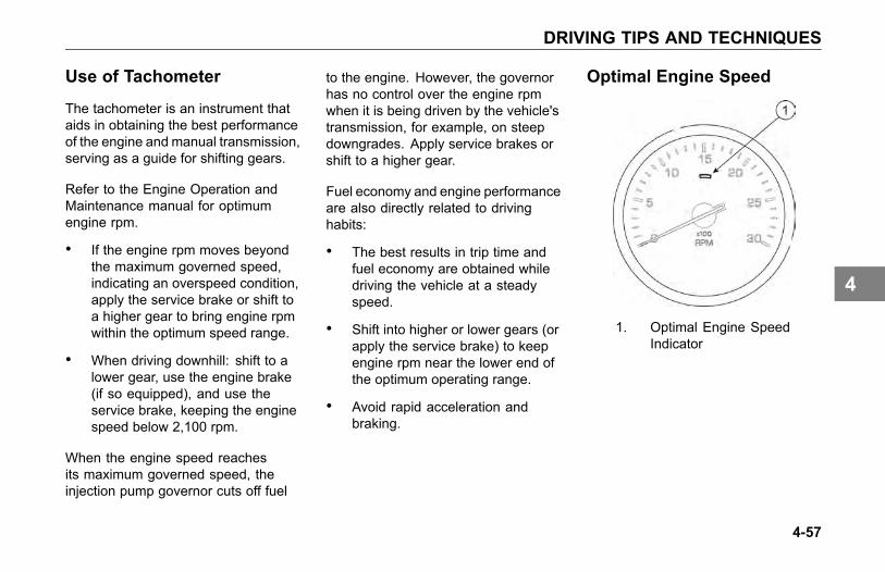
DRIVING TIPS AND TECHNIQUES
Use of Tachometer
The tachometer is an instrument thataids in obtaining the best performanceof the engine and manual transmission,serving as a guide for shifting gears.
Refer to the Engine Operation andMaintenance manual for optimumengine rpm.
• If the engine rpm moves beyondthe maximum governed speed,indicating an overspeed condition,apply the service brake or shift toa higher gear to bring engine rpmwithin the optimum speed range.
• When driving downhill: shift to alower gear, use the engine brake(if so equipped), and use theservice brake, keeping the enginespeed below 2,100 rpm.
When the engine speed reachesits maximum governed speed, theinjection pump governor cuts off fuel
to the engine. However, the governorhas no control over the engine rpmwhen it is being driven by the vehicle'stransmission, for example, on steepdowngrades. Apply service brakes orshift to a higher gear.
Fuel economy and engine performanceare also directly related to drivinghabits:
• The best results in trip time andfuel economy are obtained whiledriving the vehicle at a steadyspeed.
• Shift into higher or lower gears (orapply the service brake) to keepengine rpm near the lower end ofthe optimum operating range.
• Avoid rapid acceleration andbraking.
Optimal Engine Speed
1. Optimal Engine SpeedIndicator
4-57
4

DRIVING TIPS AND TECHNIQUES
WARNING
Do not look at the Instrument ClusterDisplay for prolonged periods or atit repeatedly in a short period oftime while the vehicle is moving.Extended glance durations toinstrument cluster and or overlyfrequent glances inside the vehiclecan cause a loss of attention tothe situations on the roadwayand vehicle’s road position, whichcould lead to an accident andpossible death or personal injury orequipment damage.
The tachometer displays a green barjust below the most efficient enginespeed for the vehicle. The placementand size of this bar is dependent onthe engine as installed at the factory.The driver’s general goal shouldbe to select a gear that keeps thetachometer needle positioned overthe green light as much as possible
during steady state driving. In additionto proper maintenance and gooddriving habits, this visual cue can helpminimize the fuel consumption.
Use of Instrument ClusterDisplay
The Instrument cluster displayprovides information to help the driveroptimize vehicle efficiency. Refer toInstrumentation Cluster Information onpage 3-14 for details. A driver will findthe section describing Trip Informationand the RPM Detail useful.
4-58
4

DRIVING TIPS AND TECHNIQUES
Fuel - Excess Consumption
The vehicle's fuel consumption isconnected to three important factors:maintenance, driving habits, andgeneral condition of the road, trafficconditions, and vehicle load.
Maintenance
Proper maintenance will keep thevehicle running like new even afterlong periods of use. The driver mustperform the daily and weekly checksof the vehicle.
Maintenance factors affectingfuel consumption:
• air and/or fuel filters partiallyclogged
• engine valves out of adjustment
• injection pump improperlysynchronized
• injection nozzles defective oruncalibrated
• improperly inflated tires
• wheel bearings improperlyadjusted
• clutch improperly adjusted or worn(slipping)
• fuel leaks
4-59
4
DRIVING TIPS AND TECHNIQUES
Driving Habits
Wrong driving habits must becorrected and the recommendationson economic driving should befollowed.
Driving factors affecting fuelconsumption:
• excessive speed and unnecessaryfast acceleration
• long periods of idling
• driving with foot resting on the(manual transmission) clutchpedal
General Condition
Other factors affecting fuelconsumption are related to loadsand type of roads on which the vehicleoperates. It is not always possible tochoose the most adequate road, butit must be kept in mind that the idealroad is the one that allows a steadyspeed in high gear, without requiringfrequent braking and acceleration.
The following generalconditions can affect fuelconsumption:
• overload
• unbalanced load
• very high load
• inadequate roads
• traffic conditions
4-60
4

SLEEPER BUNKS
SLEEPER BUNKS
Sleeper Bunk
If your vehicle has an upper and lowerbunk, the upper bunk can be folded upout of the way to provide you with moredressing area in the sleeper cab. Thelower bunk has storage underneathit to stow your luggage and otherbelongings. The upper bunk weightlimit is 320 lb. (145 kg).
WARNING
Be sure the restraint system isused when anyone is occupying thesleeper while the vehicle is moving.In an accident, an unrestrainedperson lying in a sleeper bunk couldbe injured. He or she could bethrown from the bunk.
WARNING
Always keep the lower bunk in itsdown (latched) position while thevehicle is moving. If left open, storeditems could become loose during anaccident and strike you. Before youmove the vehicle, check to be surethe lower bunk is latched securely.Failure to comply may result in deathor personal injury.
• Before you move the vehicle,check to be sure the lowerbunk is latched securely.
To Lower Upper Bunk: pull on thelanyard in the upper left corner of thebunk to release the bunk. This will freeit from the anchored position and allowyou to lower the bunk.
To Raise Upper Bunk: fold theupper bunk up and push it against theretaining latch until you hear a click.
Pull on the bunk to be sure it is latchedsecurely.
WARNING
Be sure the latch that holds theupper bunk in the folded position isworking properly so the bunk will notfall down. If the bunk falls, you couldbe injured.
WARNING
Be sure to stow away all loosebelongings before you move yourvehicle. Do not store objectson the bunks, they could causedamage or injury in an accident.Failure to comply may result indeath, personal injury, equipment orproperty damage.
4-61
4

SLEEPER BUNKS
WARNING
Be sure the restraint system isused when anyone is occupying thesleeper while the vehicle is moving.In an accident, an unrestrainedperson lying in a sleeper bunkcould be injured. He or she couldbe thrown from the bunk. Failureto comply may result in death orpersonal injury.
WARNING
Be sure no one ever rides unsecuredin the upper bunk. That personcould be thrown out in an accidentand could be injured. Do not use theupper bunk while you are moving.Failure to comply may result in deathor personal injury.
Sleeper Occupant Restraint
The sleeper restraint is stored in acompartment on the rear sleeper cabwall.
WARNING
Failure to properly use the sleeperrestraint when an individual islocated in the sleeper bunk and thevehicle is moving can result in deathor personal injury.
See Sleeper Bunks and Restraints onpage 1-25, for more information oncab/seat restraint systems.
4-62
4

STOPPING THE ENGINE
STOPPING THE ENGINE
Before Stopping the Engine
A hot engine stores a great amount ofheat. It doesn’t cool down immediatelyafter you shut it off. Always cool yourengine down before shutting it off. Youwill greatly increase its service life.
Idle the engine at 1000 RPM forfive minutes. Then low idle for thirtyseconds before shutdown. This willallow circulating coolant and lubricatingoil to carry away heat from the cylinderhead, valves, pistons, cylinder liners,turbocharger, and bearings. Thisway you can prevent serious enginedamage that may result from unevencooling.
Turbochargers
This cooling-down practice isespecially important on a turbochargedengine. The turbocharger containsbearings and seals that are subjectedto hot exhaust gases. While theengine is operating, heat is carriedaway by circulating oil. If you stop theengine suddenly, the temperature ofthe turbocharger could rise as much as100°F (55°C) above the temperaturereached during operation. A suddenrise in temperature like this couldcause the bearings to seize or the oilseals to loosen.
Refueling
Air inside the fuel tanks allows waterto condense in the tank. To preventthis condensation while the vehicle isparked for extended periods of time,fill the tanks to 95 percent of capacity.Never fill to more than 95 percentcapacity as this provides room forexpansion resulting from temperatureextremes. When refueling, addapproximately the same amount toeach fuel tank on vehicles with morethan one tank.
WARNING
Do not carry additional fuelcontainers in your vehicle. Fuelcontainers, either full or empty,may leak, explode, and cause orfeed a fire. Do not carry extrafuel containers, even empty onesare dangerous. Failure to complymay result in death, personal injury,equipment or property damage.
4-63
4

STOPPING THE ENGINE
WARNING
Diesel fuel in the presence of anignition source (such as a cigarette)could cause an explosion. A mixtureof gasoline or alcohol with diesel fuelincreases this risk of explosion. Donot remove a fuel tank cap near anopen flame. Use only the fuel and/oradditives recommended for yourengine. Failure to comply may resultin death, personal injury, equipmentor property damage.
Specification: Use only UltraLow Sulfur Diesel (ULSD) Fuel,as recommended by enginemanufacturers. If you need furtherinformation on fuel specifications,consult the Engine Operation andMaintenance Manual.
Location of Fuel Shut-OffValves
If your vehicle is equipped with shut-offvalves for the take-off and return lines,they are located on the fuel linesentering the top of the fuel tank. Fuelshut-off valves for the fuel crossoverline are on the bottom of the fuel tank,at the crossover line connection.
Refuel Before the Final Stop
Air space in your fuel tanks allowswater to condense there. To preventthis condensation while you arestopped, fill your tanks to 95% ofcapacity.
4-64
4
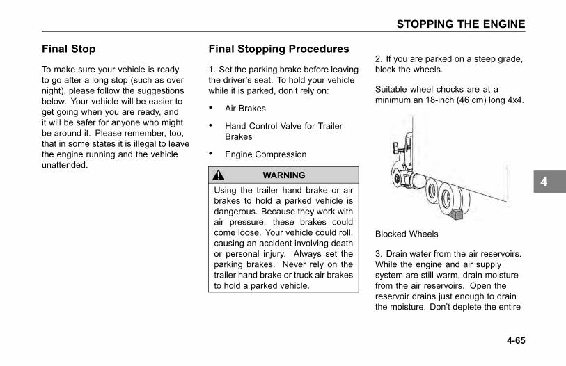
STOPPING THE ENGINE
Final Stop
To make sure your vehicle is readyto go after a long stop (such as overnight), please follow the suggestionsbelow. Your vehicle will be easier toget going when you are ready, andit will be safer for anyone who mightbe around it. Please remember, too,that in some states it is illegal to leavethe engine running and the vehicleunattended.
Final Stopping Procedures
1. Set the parking brake before leavingthe driver’s seat. To hold your vehiclewhile it is parked, don’t rely on:
• Air Brakes
• Hand Control Valve for TrailerBrakes
• Engine Compression
WARNING
Using the trailer hand brake or airbrakes to hold a parked vehicle isdangerous. Because they work withair pressure, these brakes couldcome loose. Your vehicle could roll,causing an accident involving deathor personal injury. Always set theparking brakes. Never rely on thetrailer hand brake or truck air brakesto hold a parked vehicle.
2. If you are parked on a steep grade,block the wheels.
Suitable wheel chocks are at aminimum an 18-inch (46 cm) long 4x4.
Blocked Wheels
3. Drain water from the air reservoirs.While the engine and air supplysystem are still warm, drain moisturefrom the air reservoirs. Open thereservoir drains just enough to drainthe moisture. Don’t deplete the entire
4-65
4

STOPPING THE ENGINE
air supply. Be sure to close the drainsbefore leaving the vehicle.
Opening Drains
4. Secure the vehicle. Close all thewindows and lock all the doors.
4-66
4

MAINTENANCE
PREVENTIVE MAINTENANCE SCHEDULEIntroduction . . . . . . . . . . . . . . . . . . 5-9Maintenance Schedule . . . . . . . . . . . . 5-12
LUBRICANT SPECIFICATIONSIntroduction . . . . . . . . . . . . . . . . . 5-34Engine . . . . . . . . . . . . . . . . . . . 5-34Master Lubrication Index . . . . . . . . . . . . 5-37Fuller Transmission Lubrication . . . . . . . . . 5-40Allison Transmission Lubrication . . . . . . . . 5-42Spicer Transmission Lubrication . . . . . . . . 5-42Oil Changes . . . . . . . . . . . . . . . . . 5-43Meritor Axle Lubrication . . . . . . . . . . . . 5-44Eaton/Dana Axle Lubrication . . . . . . . . . . 5-45Wheel Bearing Lubrication . . . . . . . . . . . 5-46Universal Joint Lubrication . . . . . . . . . . . 5-46Steering Gear Lubrication . . . . . . . . . . . 5-47
5-1
5
MAINTENANCE
AIR SYSTEMIntroduction . . . . . . . . . . . . . . . . . 5-48Air Dryer . . . . . . . . . . . . . . . . . . . 5-51Air Tanks . . . . . . . . . . . . . . . . . . 5-53Air Gauges and Air Leaks . . . . . . . . . . . 5-54Air Compressor . . . . . . . . . . . . . . . . 5-55
BRAKE SYSTEMBrake Adjustment . . . . . . . . . . . . . . . 5-57
CABExterior Maintenance . . . . . . . . . . . . . 5-62Cleaning, Protecting and Weather Stripping . . . 5-63Safety Restraint System - Inspection . . . . . . 5-66Windshield Wiper/Washer . . . . . . . . . . . 5-70
COOLING SYSTEMCooling system maintenance . . . . . . . . . 5-71Engine (Block) Heater . . . . . . . . . . . . . 5-75
5-2
5

MAINTENANCE
ELECTRICALElectrical System . . . . . . . . . . . . . . . 5-76Light Bulbs . . . . . . . . . . . . . . . . . . 5-77Bulb Specifications . . . . . . . . . . . . . . 5-78Fuses, Circuit Breakers and Relays . . . . . . . 5-78Fuse Inspection and Replacement . . . . . . . 5-82Adding Electrical Options . . . . . . . . . . . 5-82Batteries . . . . . . . . . . . . . . . . . . . 5-83Battery Care . . . . . . . . . . . . . . . . . 5-87Battery Charging . . . . . . . . . . . . . . . 5-87Electrical and Alternator Precautions . . . . . . 5-90Remote Keyless Entry . . . . . . . . . . . . . 5-90
ENGINEEngine Maintenance . . . . . . . . . . . . . 5-91Engine Lubrication . . . . . . . . . . . . . . 5-92Accessory Drive Belts . . . . . . . . . . . . . 5-95Engine Fan . . . . . . . . . . . . . . . . . 5-96Air Intake System . . . . . . . . . . . . . . . 5-97
5-3
5

MAINTENANCE
Turbocharger . . . . . . . . . . . . . . . . . 5-97Air Cleaners . . . . . . . . . . . . . . . . . 5-98Filter Minder . . . . . . . . . . . . . . . . . 5-99Exhaust System . . . . . . . . . . . . . . . 5-99
FUEL SYSTEMLocation of Fuel Shut-off Valves. . . . . . . . . 5-100Specification . . . . . . . . . . . . . . . . . 5-100Fuel Filters . . . . . . . . . . . . . . . . . . 5-100
FRAMEIntroduction . . . . . . . . . . . . . . . . . 5-102
FRONT AXLE AND SUSPENSIONAxle Lubrication . . . . . . . . . . . . . . . 5-106Inspection . . . . . . . . . . . . . . . . . . 5-107Wheel Alignment . . . . . . . . . . . . . . . 5-107U-Bolt Torque . . . . . . . . . . . . . . . . 5-108
HEATER AND AIR CONDITIONERIntroduction . . . . . . . . . . . . . . . . . 5-110
5-4
5
MAINTENANCE
Air Filters . . . . . . . . . . . . . . . . . . 5-111Heater. . . . . . . . . . . . . . . . . . . . 5-113Air Conditioner . . . . . . . . . . . . . . . . 5-114
NOISE AND EMISSION CONTROLNoise Emission Warranty . . . . . . . . . . . 5-115Inspection and Maintenance Instructions . . . . . 5-117Noise Control System - Maintenance Log . . . . 5-122
REAR AXLE AND SUSPENSIONGeneral Maintenance . . . . . . . . . . . . . 5-124Visual Inspection . . . . . . . . . . . . . . . 5-125Rear Suspension Fasteners . . . . . . . . . . 5-126Rear Axle Lubrication . . . . . . . . . . . . . 5-127Rear Axle Alignment . . . . . . . . . . . . . 5-129
STEERING SYSTEMPower Steering . . . . . . . . . . . . . . . . 5-130Fluid Level and Refill . . . . . . . . . . . . . 5-131Steering Shaft . . . . . . . . . . . . . . . . 5-132
5-5
5

MAINTENANCE
DRIVELINEDriveshaft Maintenance . . . . . . . . . . . . 5-134U-Joints . . . . . . . . . . . . . . . . . . . 5-134
TIRES AND WHEELTires . . . . . . . . . . . . . . . . . . . . 5-135Wheel Mounting and Fastening . . . . . . . . . 5-140Wheel Replacement With Disc Brake Option . . . 5-142Disc Wheels . . . . . . . . . . . . . . . . . 5-144
WHEEL BEARINGWheel Bearing Adjustment . . . . . . . . . . . 5-145
TRANSMISSION MAINTENANCEIntroduction . . . . . . . . . . . . . . . . . 5-146Transmission Lubricants . . . . . . . . . . . . 5-147Automatic Transmissions . . . . . . . . . . . 5-148
CLUTCHIntroduction . . . . . . . . . . . . . . . . . 5-149Clutch Hydraulic Fluid . . . . . . . . . . . . . 5-149
5-6
5

MAINTENANCE
Clutch Adjustment . . . . . . . . . . . . . . 5-150Clutch Adjustment - Normal Wear . . . . . . . . 5-150
5-7
5


PREVENTIVE MAINTENANCE SCHEDULE
PREVENTIVEMAINTENANCESCHEDULE
Introduction
Preventive maintenance programbegins with the daily checks. SeeDriver’s Check List on page 1-33for these routine checks. Routinevehicle checks can help avoid manylarge, expensive, and time consumingrepairs. The vehicle will operate better,be safer, and last longer. Neglectof recommended maintenance canvoid your vehicle’s warranty. Somemaintenance operations demandskills and equipment you may nothave. For such situations, please takeyour vehicle to an authorized ServiceCenter.
WARNING
Before attempting any proceduresin the engine compartment, stopthe engine and let it cool down.Hot components can burn skin oncontact. Failure to comply mayresult in death, personal injury,equipment or property damage.
WARNING
If the engine must be operatingto inspect, be alert and cautiousaround the engine at all times.Failure to comply may result indeath, personal injury, equipment orproperty damage.
WARNING
If work has to be done with theengine running, always (1) setthe parking brake, (2) block thewheels, and (3) ensure that theshift lever or selector is in Neutral.Failure to comply may result indeath, personal injury, equipment orproperty damage.
WARNING
Exercise extreme caution to preventneckties, jewelry, long hair, or looseclothing from getting caught in thefan blades or any other movingengine parts. Failure to complymay result in death, personal injury,equipment or property damage.
5-9
5

PREVENTIVE MAINTENANCE SCHEDULE
WARNING
Disconnect the battery ground strapwhenever you work on the fuelsystem or the electrical system.When you work around fuel, donot smoke or work near heatersor other fire hazards. Keep anapproved fire extinguisher handy.Failure to comply may result indeath, personal injury, equipment orproperty damage.
WARNING
Always support the vehicle withappropriate safety stands if it isnecessary to work underneath thevehicle. A jack is not adequatefor this purpose. Failure to complymay result in death, personal injury,equipment or property damage.
WARNING
When working underneath thevehicle without appropriate safetystands but with the wheels on theground (not supported), make surethat (1) the vehicle is on hard levelground, (2) the parking brake isapplied, (3) all wheels are blocked(front and rear) and (4) removethe ignition key so that the enginecannot be started. Failure to complymay result in death, personal injury,equipment or property damage.
WARNING
Never start or let the enginerun in an enclosed, unventilatedarea. Exhaust fumes from theengine contain carbon monoxide, acolorless and odorless gas. Carbonmonoxide can be fatal if inhaled.Failure to comply may result indeath, personal injury, equipment orproperty damage.
The following pages contain a tableof maintenance tasks with the relatedintervals for each task on the rightside of the table. The top of the tabledisplays a guide to a maintenanceinterval and its schedule. Sometasks are dependent on the vehicleapplication. These tasks will beshown as separate tasks and will havethe words “ON HIGHWAY”, “CITYDELIVERY” or “OFF-HIGHWAY”after the description. These tasksare differentiated because they are
5-10
5

PREVENTIVE MAINTENANCE SCHEDULE
dependent on the vehicle’s operatingenvironment.
On highway is defined for applicationswhere the vehicle is NOT used off of apaved road during normal operation.
City Delivery is defined for applicationswhere frequent start and stopping isrequired during normal operation andthe highway is used infrequently andfor short periods of time.
Off highway is defined for applicationswhere the vehicle may be driven offthe pavement on a regular basis, evenif it is an infrequent basis and/or for abrief time period.
Please contact an authorizedservice dealership if there arequestions regarding which intervalto follow. Consult the supplier forspecific recommendations wherediscrepancies develop between these
recommendations in this table andcomponent supplier recommendations.
• Engine lubricating oil changeintervals aren’t listed here. Referto your engine’s operating manualfor recommendations. For specificinformation on maintenanceprocedures consult your vehiclemaintenance manual.
• The initial fill of drive axle lubricantmust be changed before the endof the first scheduled maintenanceinterval. Refer to Oil Changes onpage 5-43 before you put a newvehicle into service.
• The initial fill of lubricant inmanual transmissions must bechanged before the end of the firstmaintenance interval. See FullerTransmission Lubrication on page5-40 for specific information.
• If your vehicle is equipped with anautomatic transmission, consult
the owner’s manual for it that camewith your vehicle to obtain lubricantcheck and change intervals.
5-11
5

PREVENTIVE MAINTENANCE SCHEDULE
Maintenance ScheduleNew Vehicle Maintenance Schedule
New Vehicle Maintenance ScheduleAfter First Miles (km)
Operation\Frequency First Day50 – 100(80 – 160)
500 (800) 2,000(3218)
3,000–5,000(4800–8000)
Steering Shaft U-Bolts. (OFF-HIGHWAY) See Steering System on page 5-130. XWheel Mounting. See Wheel Mounting and Fastening on page 5-140. XFront Axle U-Bolt Torque. See Front Spring Suspension U-Bolts on page 5-108. XCharge Air Cooler and Air Intake Pipe Clamps, re- torque fasteners. XRear Suspension Fasteners. See Rear Suspension Fasteners on page 5-126. XTransmission Lubrication.1. For Fuller transmission, see Fuller Transmission Lubrication on page 5-40.2. For Allison transmission, see Allison Transmission Lubrication on page 5-42.3. For Spicer transmission, see Spicer Transmission Lubrication on page 5-42.
X
Axle Lubrication.1. For Meritor axle, see Meritor Axle Lubrication on page 5-44.2. For Eaton/Dana axle, see Eaton/Dana Axle Lubrication on page 5-45.
X
5-12
5
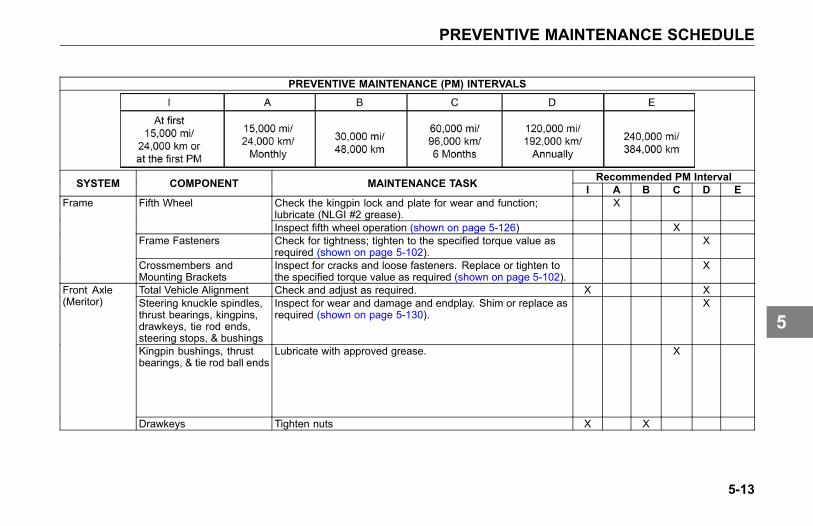
PREVENTIVE MAINTENANCE SCHEDULE
PREVENTIVE MAINTENANCE (PM) INTERVALS
Recommended PM IntervalSYSTEM COMPONENT MAINTENANCE TASK I A B C D ECheck the kingpin lock and plate for wear and function;lubricate (NLGI #2 grease).
XFifth Wheel
Inspect fifth wheel operation (shown on page 5-126) XFrame Fasteners Check for tightness; tighten to the specified torque value as
required (shown on page 5-102).X
Frame
Crossmembers andMounting Brackets
Inspect for cracks and loose fasteners. Replace or tighten tothe specified torque value as required (shown on page 5-102).
X
Total Vehicle Alignment Check and adjust as required. X XSteering knuckle spindles,thrust bearings, kingpins,drawkeys, tie rod ends,steering stops, & bushings
Inspect for wear and damage and endplay. Shim or replace asrequired (shown on page 5-130).
X
Kingpin bushings, thrustbearings, & tie rod ball ends
Lubricate with approved grease. X
Front Axle(Meritor)
Drawkeys Tighten nuts X X
5-13
5

PREVENTIVE MAINTENANCE SCHEDULE
PREVENTIVE MAINTENANCE (PM) INTERVALS
Recommended PM IntervalSYSTEM COMPONENT MAINTENANCE TASK I A B C D ETotal Vehicle Alignment Check and adjust as required. X XKingpin bushings, thrustbearings, & tie rod ball ends(ON HIGHWAY)
Lubricate with approved grease. X
Kingpin bushings, thrustbearings, & tie rod ball ends(OFF-HIGHWAY)
Lubricate with approved grease. X
Steering knuckle spindles,thrust bearings, kingpins,drawkeys, tie rod ends,steering stops, & bushings(ON HIGHWAY)
Inspect for wear and damage and for endplay. Shim or replaceas required.
X
Front Axle(Dana)
Steering knuckle spindles,thrust bearings, kingpins,drawkeys, tie rod ends,steering stops, & bushings(OFF-HIGHWAY)
Inspect for wear and damage and for endplay. Shim or replaceas required.
X
5-14
5

PREVENTIVE MAINTENANCE SCHEDULE
PREVENTIVE MAINTENANCE (PM) INTERVALS
Recommended PM IntervalSYSTEM COMPONENT MAINTENANCE TASK I A B C D EFront Spring Inspect for cracked leaves, worn bushings, & excessive
corrosion.X
Spring Pins & Shackles Inspect for worn parts and excessive joint clearance. Shimor replace as required.
X
Shock Absorbers Inspect for leaking, body damage, and damaged or wornbushings. Replace as required. Check the shock mountingstud torque.
X
Lubricate with approved grease. XSpring PinsCheck for proper function. X
U-bolts (ON HIGHWAY) Check the general condition and the tightness of the nuts.Tighten the nuts to the specified torque value as required(shown on page 5-109).
X X
FrontSuspension
U-bolts (OFF HIGHWAY) Check the general condition and the tightness of the nuts.Tighten the U-bolts after the first day or two of operation.Then tighten the nuts to the specified torque value as required(shown on page 5-109).
X
5-15
5

PREVENTIVE MAINTENANCE SCHEDULE
PREVENTIVE MAINTENANCE (PM) INTERVALS
Recommended PM IntervalSYSTEM COMPONENT MAINTENANCE TASK I A B C D EVisually inspect for damage or leaks. XCheck oil level. Check “cold.” Torque the drain plug. X
Axle Housing
Drain the lubricant while warm. Flush each unit with cleanflushing oil. Change the lubricant.
See information on page 5-44
Check the lubricant level. XAir Shift UnitRemove the housing cover and drain the lubricant. Wash theparts thoroughly and dry in air.
X
Breather Clean or replace. XLube Pump (ON HIGHWAY) Remove the magnetic strainer and inspect for wear particles.
Wash in solvent and dry in air.X
Lube Pump (OFFHIGHWAY)
Remove the magnetic strainer and inspect for wear particles.Wash in solvent and dry in air.
X
Lube Filter (ON HIGHWAY) Change. XLube Filter (OFFHIGHWAY)
Change. X
Magnetic drain plug andbreather (ON HIGHWAY)
Clean or replace. X
Drive Axle(Dana)
Magnetic drain plug andbreather (OFF HIGHWAY)
Clean or replace. X
5-16
5
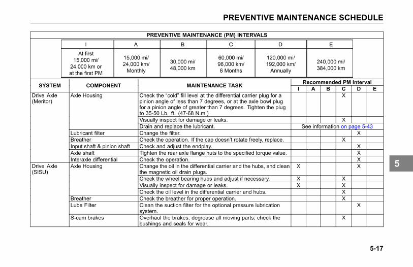
PREVENTIVE MAINTENANCE SCHEDULE
PREVENTIVE MAINTENANCE (PM) INTERVALS
Recommended PM IntervalSYSTEM COMPONENT MAINTENANCE TASK I A B C D ECheck the “cold” fill level at the differential carrier plug for apinion angle of less than 7 degrees, or at the axle bowl plugfor a pinion angle of greater than 7 degrees. Tighten the plugto 35-50 Lb. ft. (47-68 N.m.)
X
Visually inspect for damage or leaks. X
Axle Housing
Drain and replace the lubricant. See information on page 5-43Lubricant filter Change the filter. XBreather Check the operation. If the cap doesn’t rotate freely, replace. XInput shaft & pinion shaft Check and adjust the endplay. XAxle shaft Tighten the rear axle flange nuts to the specified torque value. X
Drive Axle(Meritor)
Interaxle differential Check the operation. XChange the oil in the differential carrier and the hubs, and cleanthe magnetic oil drain plugs.
X X
Check the wheel bearing hubs and adjust if necessary. X XVisually inspect for damage or leaks. X X
Axle Housing
Check the oil level in the differential carrier and hubs. XBreather Check the breather for proper operation. XLube Filter Clean the suction filter for the optional pressure lubrication
system.X
Drive Axle(SISU)
S-cam brakes Overhaul the brakes; degrease all moving parts; check thebushings and seals for wear.
X
5-17
5

PREVENTIVE MAINTENANCE SCHEDULE
PREVENTIVE MAINTENANCE (PM) INTERVALS
Recommended PM IntervalSYSTEM COMPONENT MAINTENANCE TASK I A B C D EU-bolts Check the torque. Tighten to specified torque value as required
(shown on page 5-127).X X
Frame & crossmemberbolts
Check the torque. Tighten to specified torque value as required(shown on page 5-104).
X
RearSuspension
Mounting brackets andfasteners
Check the condition and the fastener torque. Tighten to thespecified torque value as required (shown on page 5-104).
X X
5-18
5
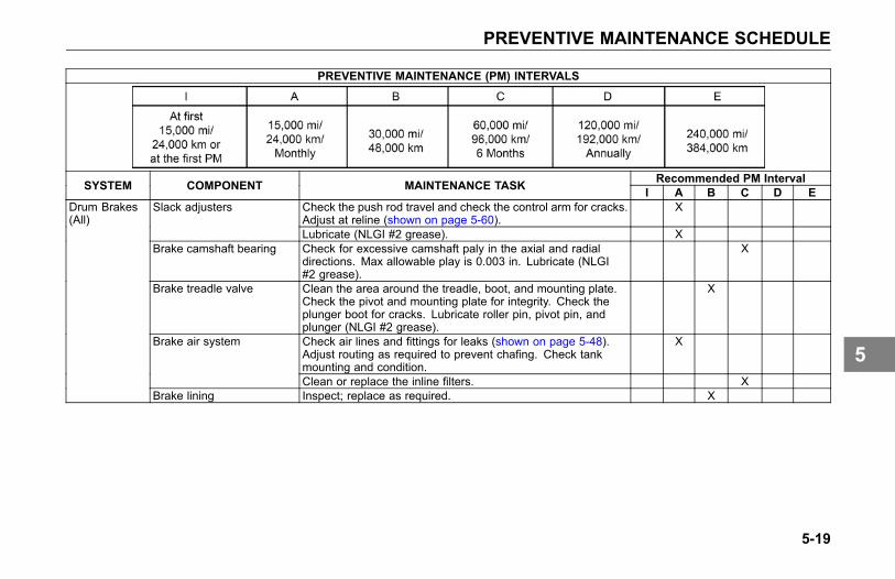
PREVENTIVE MAINTENANCE SCHEDULE
PREVENTIVE MAINTENANCE (PM) INTERVALS
Recommended PM IntervalSYSTEM COMPONENT MAINTENANCE TASK I A B C D ECheck the push rod travel and check the control arm for cracks.Adjust at reline (shown on page 5-60).
XSlack adjusters
Lubricate (NLGI #2 grease). XBrake camshaft bearing Check for excessive camshaft paly in the axial and radial
directions. Max allowable play is 0.003 in. Lubricate (NLGI#2 grease).
X
Brake treadle valve Clean the area around the treadle, boot, and mounting plate.Check the pivot and mounting plate for integrity. Check theplunger boot for cracks. Lubricate roller pin, pivot pin, andplunger (NLGI #2 grease).
X
Check air lines and fittings for leaks (shown on page 5-48).Adjust routing as required to prevent chafing. Check tankmounting and condition.
XBrake air system
Clean or replace the inline filters. X
Drum Brakes(All)
Brake lining Inspect; replace as required. X
5-19
5

PREVENTIVE MAINTENANCE SCHEDULE
PREVENTIVE MAINTENANCE (PM) INTERVALS
Recommended PM IntervalSYSTEM COMPONENT MAINTENANCE TASK I A B C D EBrake pads Inspect; replace as required. XBrake disc/rotor Inspect for visible cracks, heat checking, galling, or scoring of
surface. Check for runout (max allowable is 0.002 in.).X
Caliper sliding function Ensure caliper slides freely with no obstructions or excessiveplay.
X
Caliper slide pins Inspect protective caps of the guide pins for damage orcracking.
X
Disc Brakes(Bendix®)
System operation Check operation; inspect as per manufacturer’s serviceliterature.
X
5-20
5

PREVENTIVE MAINTENANCE SCHEDULE
PREVENTIVE MAINTENANCE (PM) INTERVALS
Recommended PM IntervalSYSTEM COMPONENT MAINTENANCE TASK I A B C D EHubs (non-LMS) Check the bearing endplay and adjust as required (shown on
page 5-46).X
Hubs (non-LMS) withoutrunner seals
Clean the components and check for excessive wear ordamage. Change the oil and seal (shown on page 5-46).
X
Hubs (non-LMS) withstandard seals
Clean the components and check for excessive wear ordamage. Change the oil and seal (shown on page 5-46).
X
Hub seals (all) Check for leaks; replace as required. XLMS Hubs (Dana) Inspect for leaks. Check the bearing endplay and adjust as
required (shown on page 5-46).X
LMS Hubs (Dana) withSynthetic Lubricant
Service the bearings, seals and oil. This interval may bedifferent depending on the results of the regular inspection.(shown on page 5-46).
500,000 miles/ 800,000 km
LMS Hubs (Dana) withMineral Lubricant
Service the bearings, seals and oil. This interval may bedifferent depending on the results of the regular inspection.(shown on page 5-46).
350,000 miles/ 560,000 km
Brake drums Inspect for visible cracks, heat checking, galling or scoring ofthe braking surface, and for severe corrosion on the outsidesurface. Check for out-of-round or oversize condition [0.080 in.(2 mm) more than the original diameter]. Replace as required.
X
Hub, Drum, &Hubcap
Hubcaps Clean the sight window. Check the center plug, mountingflange, and fill plug for leaks and for proper installation.Replace broken or damaged parts. Check the lubricant leveland add as required.
X
5-21
5

PREVENTIVE MAINTENANCE SCHEDULE
PREVENTIVE MAINTENANCE (PM) INTERVALS
Recommended PM IntervalSYSTEM COMPONENT MAINTENANCE TASK I A B C D EInspect for visible damage, signs of overheating, and leaks. X XMain & auxiliary
transmission and transfercase
Check the drain plugs for tightness. X
Mounting Brackets andFasteners
Check the condition of the fasteners and their torque. Tightento the specified torque value as required.
X
Oil cooler Clean the fins (air-to-oil type) and body. Check the hosecondition and for leaks; replace as required.
X
Main & aux. transmission Check the oil level; refill as required. XMain & auxiliarytransmission (ONHIGHWAY)
Drain lubricant while warm. Flush each unit with clean flushingoil.
500,000 miles/ 800,000 km
Main &auxiliarytransmission
Main & auxiliarytransmission (OFFHIGHWAY)
Drain lubricant while warm. Flush each unit with clean flushingoil.
X X
Inspect: Check oil level; inspect for leaks and any visibledamage.
X
Initial oil change: Drain oil while warm; flush case with gearoil-compatible fluid; clean magnetic drain plug; refill. Do notflush the case with any solvent.
X X
Auxiliarytransmission
Cotta Transfer CaseTR2205Fabco Transfer CaseTC142/TC143/TC170/TC270Marmon-HarringtonTransfer CaseMVG2000/MVG2000SD
Change oil. X
5-22
5

PREVENTIVE MAINTENANCE SCHEDULE
PREVENTIVE MAINTENANCE (PM) INTERVALS
Recommended PM IntervalSYSTEM COMPONENT MAINTENANCE TASK I A B C D EAir intake piping, mounting,and charge air cooler
Check the system for broken pipes, leaks, joint integrity,cleanliness, and proper support (shown on page 5-97).
X
Cold starting aids Check for leaks and proper operation (shown on page 4-10). X
Air Intake
Air cleaner Replace the engine intake air cleaner element (shown on page5-99).
When required by air restrictionindicator or required by the engine
manufacturers operator manual.Clutch hydraulic fluid Replace fluid and bleed system. XClutch release bearing Lubricate. X
Clutch
Inspect and adjust when necessary (no adjustment requiredfor SOLO type clutches)
X
5-23
5

PREVENTIVE MAINTENANCE SCHEDULE
PREVENTIVE MAINTENANCE (PM) INTERVALS
Recommended PM IntervalSYSTEM COMPONENT MAINTENANCE TASK I A B C D EHoses Check the radiator and heater hoses for leaks. X X
Check the freeze point (shown on page 5-72). XCheck for contamination using test strips (shown on page 5-71). XReplace blank water filter if applicable. XPerform lab analysis (shown on page 5-71).If lab analysis shows coolant is unsuitable for continued use:Flush, drain, and refill (shown on page 5-71).Add ELC Extender (shown on page 5-71).
X
Extended Life Coolant(ELC)
Flush, drain, and refill with new coolant (shown on page 5-71). XFan clutch Check for air leaks. (shown on page 5-96).
Check the fan drive bearings (turn the sheave in both directionsto check for worn hub bearings).
X X
Cooling
Solenoid valve Check the fan drive for proper engagement and disengagement. X X
5-24
5

PREVENTIVE MAINTENANCE SCHEDULE
PREVENTIVE MAINTENANCE (PM) INTERVALS
Recommended PM IntervalSYSTEM COMPONENT MAINTENANCE TASK I A B C D ECheck inflation pressure (shown on page 5-135). Weekly “cold” using calibrated gaugeTiresInspect for cuts, irregular wear, missing lugs, sidewall damage,etc.
X
Disc wheels Inspect the wheel disc for any cracks or surface irregularities.Inspect the rim edge and bead seat area for damage. Replaceany damaged wheels - DO NOT ATTEMPT TO REPAIR.
X
Demountable rims Inspect the mounting ring, rim gutter, side ring, and lock ring fordamage; replace as required.
X
Check the tightness of the fasteners and tighten the fastenersto the specified torque as required (shown on page 5-140).
X
Tires & Wheels
Wheel nuts and studs
Inspect for damaged hex corners, stripped or damagedthreads, and excessive corrosion; clean or replace as required.
X
5-25
5

PREVENTIVE MAINTENANCE SCHEDULE
PREVENTIVE MAINTENANCE (PM) INTERVALS
Recommended PM IntervalSYSTEM COMPONENT MAINTENANCE TASK I A B C D EReservoir Check the fluid level (shown on page 5-47). XReservoir (ON HIGHWAY) Drain, replace the filter, and refill (shown on page 5-47). X XReservoir (OFF HIGHWAY) Drain, replace the filter, and refill (shown on page 5-47). X X
Check the lash of the sector shaft; adjust as required. XGrease the trunnion bearing (EP NLGI #2 lithium-based,moly-filled, HD grease).
XSteering gear
Grease the input shaft seal (EP NLGI #2 lithium-based,moly-filled, HD grease).
X
Power assist cylinder Lubricate the ball joints. Inspect for leaking rod seals, damagedball joint boots, and damage to cylinder rod or barrel.
X
Hoses and tubes Check for leaks and chafing. XSteering linkage Check all joints for excessive lash; replace as required (shown
on page 5-130).X
Draglink tube clamp andball socket
Check the torque; tighten to specified torque value as required. X X
Pitman arm clamp bolt andnut
Check the torque; tighten to specified torque value as required. X X
PowerSteering
Steering intermediate shaft Check the torque on the pinch bolt and nut. X X
5-26
5

PREVENTIVE MAINTENANCE SCHEDULE
PREVENTIVE MAINTENANCE (PM) INTERVALS
Recommended PM IntervalSYSTEM COMPONENT MAINTENANCE TASK I A B C D ESteering intermediate shaftU-joints (ON HIGHWAY)
Lubricate [EP NLGI #2 HD grease, +325° F to -10° F (+163° Cto -23° C) range].
X X
Steering intermediate shaftU-joints (OFF HIGHWAY orCITY DELIVERY)
Lubricate [EP NLGI #2 HD grease, +325° F to -10° F (+163° Cto -23° C) range].
X X
Draglink and tie rod arm ballsockets (ON HIGHWAY)
Lubricate (EP NLGI #2 lithium-based, moly-filled, HD grease). X X
PowerSteering
Draglink and tie rod arm ballsockets (OFF HIGHWAY orCITY DELIVERY)
Lubricate (EP NLGI #2 lithium-based, moly-filled, HD grease). X X
Fuel tanks Inspect tanks, brackets, hoses, and fittings for correct location,tightness, abrasion damage, and leaks; repair or replace asrequired.
X
Fuel tank breathers Check for proper function; clean the drain hoses. X
Fuel & Tanks
Fuel tank straps Check the strap tightness; tighten to proper torque value asrequired:Aluminum tank: 30 Lb. ft. (41 N.m.)Cylindrical Steel tank: 8 Lb. ft. (11 N.m.)
X X
5-27
5

PREVENTIVE MAINTENANCE SCHEDULE
PREVENTIVE MAINTENANCE (PM) INTERVALS
Recommended PM IntervalSYSTEM COMPONENT MAINTENANCE TASK I A B C D ELubricate*. X XModels SPL-90, 1710 and
1810 slip member & U-joints Inspect. U-joint inspections should beperformed every time a vehicle comes
in for scheduled maintenance.**Lubricate*. XModel SPL-100 slip
member & U-joints Inspect. U-joint inspections should beperformed every time a vehicle comes
in for scheduled maintenance.**Lubricate*. X
Driveshafts
ModelsSPL-140/140HD/170/170HD/250/250HD slipmembers & U-joints (ONHIGHWAY & LINEHAUL)
Inspect. U-joint inspections should beperformed every time a vehicle comes
in for scheduled maintenance.**
5-28
5

PREVENTIVE MAINTENANCE SCHEDULE
PREVENTIVE MAINTENANCE (PM) INTERVALS
Recommended PM IntervalSYSTEM COMPONENT MAINTENANCE TASK I A B C D ELubricate*. XModels
SPL-140/140HD/170/170HD/250/250HD slipmembers & U-joints (OFFHIGHWAY)
Inspect. U-joint inspections should beperformed every time a vehicle comes
in for scheduled maintenance.**
Lubricate*. 350,000 mi (560,000 km) 1st intervaland then every 100,000 mi (160,00
km) after that.
ModelsSPL-140XL/170XL/250XLslip members and U-joints(ON HIGHWAY & LINEHAUL)
Inspect. U-joint inspections should beperformed every time a vehicle comes
in for scheduled maintenance.**Lubricate*. XModels
SPL-140XL/170XL/250XLslip members and U-joints(OFF HIGHWAY & CITY)
Inspect. U-joint inspections should beperformed every time a vehicle comes
in for scheduled maintenance.***Use only Spicer Driveshaft approved lubricants when greasing Spicer U-joints.
Driveshafts
**Refer to Spicer Driveshaft service manual DSSM-0100 (3264-SPL) for detailed instructions.
5-29
5
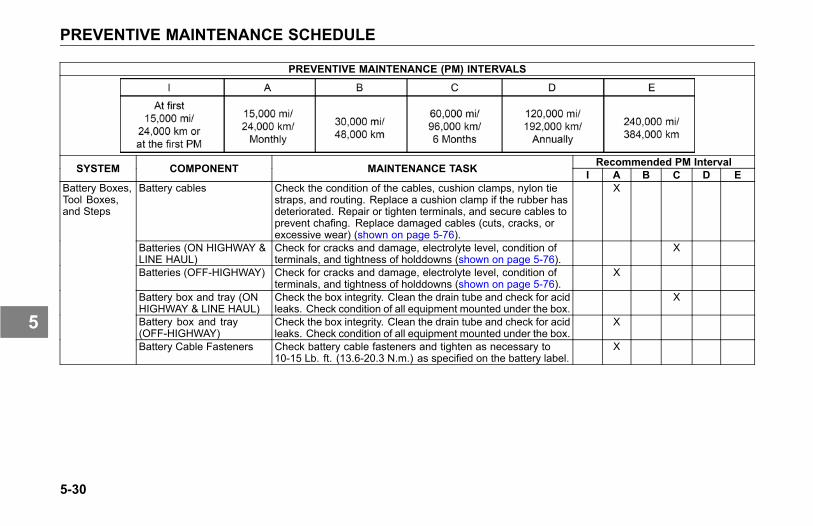
PREVENTIVE MAINTENANCE SCHEDULE
PREVENTIVE MAINTENANCE (PM) INTERVALS
Recommended PM IntervalSYSTEM COMPONENT MAINTENANCE TASK I A B C D EBattery cables Check the condition of the cables, cushion clamps, nylon tie
straps, and routing. Replace a cushion clamp if the rubber hasdeteriorated. Repair or tighten terminals, and secure cables toprevent chafing. Replace damaged cables (cuts, cracks, orexcessive wear) (shown on page 5-76).
X
Batteries (ON HIGHWAY &LINE HAUL)
Check for cracks and damage, electrolyte level, condition ofterminals, and tightness of holddowns (shown on page 5-76).
X
Batteries (OFF-HIGHWAY) Check for cracks and damage, electrolyte level, condition ofterminals, and tightness of holddowns (shown on page 5-76).
X
Battery box and tray (ONHIGHWAY & LINE HAUL)
Check the box integrity. Clean the drain tube and check for acidleaks. Check condition of all equipment mounted under the box.
X
Battery box and tray(OFF-HIGHWAY)
Check the box integrity. Clean the drain tube and check for acidleaks. Check condition of all equipment mounted under the box.
X
Battery Boxes,Tool Boxes,and Steps
Battery Cable Fasteners Check battery cable fasteners and tighten as necessary to10-15 Lb. ft. (13.6-20.3 N.m.) as specified on the battery label.
X
5-30
5

PREVENTIVE MAINTENANCE SCHEDULE
PREVENTIVE MAINTENANCE (PM) INTERVALS
Recommended PM IntervalSYSTEM COMPONENT MAINTENANCE TASK I A B C D EHeadlamps Check the aim and adjust as required. XWarning lights in light bar Check at the ignition start position to verify bulbs and driver
information display function (shown on page 3-30).X
Turn, Stop, Reverse lightsand signals
Visual check. X
Check operation and output. XCheck tightness of the pulley nut. XCheck the tension of the drive belt (shown on page 5-95). X
Alternator
Check tightness of the terminal hex nuts. XStarter Check torque on hex nuts. XECM connector Check the tightness of the ECM connector. XWheel sensors Check for damaged sensors and connectors, and worn or
frayed wires.X
Fuel and diesel exhaustfluid tank sending unit
Check the mounting screws and electrical connections for wornor damaged wires and connectors.
X X
Check for worn or damaged insulation, corroded terminals,frayed wires, and oil or fluid leaks on the connectors or wiring.
X
Electrical &lights
Power supply harnesses(engine, transmission, etc.)
Wash to remove excess grease. XHood Lubricate the lower hood pivot (only if lube fittings are present). XHinges and latch Lubricate with silicone spray. X
Cab structure,doors & hoods
Body & cab holddown bolts Check the condition and tightness. X
5-31
5

PREVENTIVE MAINTENANCE SCHEDULE
PREVENTIVE MAINTENANCE (PM) INTERVALS
Recommended PM IntervalSYSTEM COMPONENT MAINTENANCE TASK I A B C D EAir conditioner Operate the system. X
Perform the checks listed shown on page 5-110. XHeater & air conditionerFull operational and diagnostic check. X
Cabin fresh air filter (ONHIGHWAY)
Inspect and clean, replace if necessary, as shown on page5-111.
X
Cabin fresh air filter(OFF-HIGHWAY)
Inspect and clean, replace if necessary, as shown on page5-111.
X
Condenser Clear any debris from the front of the condenser. XSleeper air filter Inspect and clean, replace if necessary, as shown on page
5-112.X
Recirc cab air filter (ONHIGHWAY)
Please contact an authorized dealer when the service intervalis required to inspect the cabin recirculation air filter.
X
Heating & AirConditioning
Recirc cab air filter(OFF-HIGHWAY)
Please contact an authorized dealer when the service intervalis required to inspect the cabin recirculation air filter.
X
System Check for leaks and proper support (shown on page 5-115). XDiesel particulate filter Clean filter. Refer to the Engine Maintenance
Manual.Diesel exhaust fluid tank Inspect the tank, straps, brackets, hoses and fittings for
abrasion damage, leaks, tightness and fully engagedconnectors.
X
AftertreatmentSystem
Diesel exhaust fluid supplymodule
Replace filter. Refer to the Engine MaintenanceManual.
5-32
5
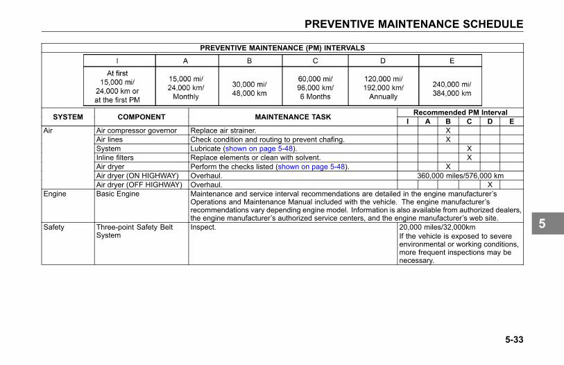
PREVENTIVE MAINTENANCE SCHEDULE
PREVENTIVE MAINTENANCE (PM) INTERVALS
Recommended PM IntervalSYSTEM COMPONENT MAINTENANCE TASK I A B C D EAir compressor governor Replace air strainer. XAir lines Check condition and routing to prevent chafing. XSystem Lubricate (shown on page 5-48). XInline filters Replace elements or clean with solvent. XAir dryer Perform the checks listed (shown on page 5-48). XAir dryer (ON HIGHWAY) Overhaul. 360,000 miles/576,000 km
Air
Air dryer (OFF HIGHWAY) Overhaul. XEngine Basic Engine Maintenance and service interval recommendations are detailed in the engine manufacturer’s
Operations and Maintenance Manual included with the vehicle. The engine manufacturer’srecommendations vary depending engine model. Information is also available from authorized dealers,the engine manufacturer’s authorized service centers, and the engine manufacturer’s web site.
Safety Three-point Safety BeltSystem
Inspect. 20,000 miles/32,000kmIf the vehicle is exposed to severeenvironmental or working conditions,more frequent inspections may benecessary.
5-33
5

LUBRICANT SPECIFICATIONS
LUBRICANTSPECIFICATIONS
Introduction
WARNING
Handle lubricants carefully. Vehiclelubricants (oil and grease) canbe poisonous and cause death,personal injury or sickness. Theycan also damage the paint on thevehicle.
In this section you will find the basicinformation you need to do the routinelubrication your vehicle requires. Ofcourse you will want to scheduleservice more frequently if you areoperating under severe conditionssuch as extreme heat or cold, withvery heavy loads, off-road, etc. Forany special service requirements,consult your service manuals and yourlubricant supplier. Please remember:one key to keeping your truck running
at top economy and in prolongingits life is proper lubrication servicing.Neglecting this essential aspect ofvehicle care can cost time and moneyin the long run.
CAUTION
Do not mix different types oflubricants. Mixing lubricants (oiland grease) of different brandsor types could damage vehiclecomponents; therefore, drain (orremove) old lubricants from the unitbefore refilling it.
Engine
Proper engine lubrication dependson the outside temperatures whereyou will be driving. Use the oilrecommended for the conditions youare most likely to be operating in. Youwill find a complete engine lubricationservice guide in the Engine OperationManual that came with your vehicle.The engine operator manual containsspecific maintenance tasks that you ora qualified service technician need toperform to maintain the engine.
5-34
5

LUBRICANT SPECIFICATIONS
WARNING
Exhaust fumes from the enginecontain carbon monoxide, acolorless and odorless gas. Apoorly maintained, damaged, orcorroded exhaust system can allowcarbon monoxide to enter the cabor sleeper. Failure to properlymaintain your vehicle could causecarbon monoxide to enter the caband cause death, personal injury orserious illness.
WARNING
Never idle your vehicle for prolongedperiods of time if you sense thatexhaust fumes are entering the cab.Investigate the cause of the fumesand correct it as soon as possible.If the vehicle must be driven underthese conditions, drive only withthe windows slightly open. Failureto repair the source of the exhaustfumes may lead to death, personalinjury or serious illness.
NOTEKeep the engine exhaust systemand the vehicle’s cab ventilationsystem properly maintained. It isrecommended that the vehicle’sexhaust system and cab beinspected:
• By a competent technician every15,000 miles/ 24,000 km
• Whenever a change is noticed inthe sound of the exhaust system
• Whenever the exhaust system,underbody, cab or sleeper isdamaged
NOTEUse only an exact replacementparts in Aftertreatment exhaustsystem. Using a noncompliantreplacement part could violateemissions requirements and alsovoid the emission system’s warranty.
5-35
5

LUBRICANT SPECIFICATIONS
Pipe and Hose Clamps
Use the following table for torquespecifications to check pipe and hoseclamps.
Pipe and Hose Clamp Torque Values
TORQUEAPPLICATION APPROVED CLAMPNm Lb-In
Radiator & Heat Exchanger Hoses Constant-Torque CT-L 10.2-12.5 90-110Heater Hoses Constant Tension not required not requiredAir Intake Pipes Hi-Torque HTM-L 11.3-14.2 100-125Plastic Air Intake Pipes Constant- Torque CT-L 4.5 40 (maximum)
Flex Seal 667 7.9-11.3 70-100Charge Air Intake HosesB9296 6-7 50-60
Fuel, Oil & Water Heat Exchangers (forhoses less than 9/16 diameter)
Miniature 3600L 1.1-1.7 10-15
5-36
5

LUBRICANT SPECIFICATIONS
Master Lubrication IndexLubricant Symbol Key
ATF MD3 or MERCON®-approved automatic transmission fluidBB High temperature ball bearing grease. Chevron SRI Mobile Grease HP, Texaco Multifax 2 or equivalentCB Engine oil for mild to moderate requirementsCC/CD Engine oil for severe requirements (MIL-L-2104B /MIL-L-45199B w/ 1.85% max. sulfated ash content)CD Engine oil meeting API “Five engine test sequence”CD50 SAE50W synthetic transmission fluidCE Engine oil meeting severe duty service requirements for direct-injection turbocharged enginesCJ-4 Engine oil for PACCAR MX and Cummins EGR enginesCL Multipurpose chassis greaseEP Extreme Pressure Lubricant (Lithium 12-hydroxystearate base NGLI 2)GL Straight mineral gear lubricantHD Hypoid Gear Oil, A.P.I. - GL-5, SAE 75W-90FE synthetic gear lubricantHT High Temperature grease (Timken Spec. 0-616)MP Multipurpose gear lubricant (MIL-L-2105B)DOT3 or DOT4 Brake Fluid
NOTEThe responsibility for meeting thesespecifications, the quality of theproduct, and its performance inservice rests with the lubricantsupplier.
For oil reservoir with side filler plugs(transmission, axles, steering gear
boxes, transfer cases, etc.) the oilmust be level with the filler opening.
1 Improper Oil Level2 Proper Oil Level
Use care when checking the oil levelwith a finger. Just because you canreach the oil level with a finger, doesnot mean the oil level is correct.
5-37
5

LUBRICANT SPECIFICATIONS
Component Lubrication IndexUniversal Joints EP*Drive Shaft Splines CL*Steering Column CLAlternator Bearing BB*Fan Hub BB*Power Steering Reservoir ATFSteering Drag Link CLSteering Knuckles CLSpring Pins CLClutch Release Bearings BBBrake Shoe Anchor Pins HTBrake Cam Bearings HTSlack Adjusters CLStarter Bearings CCTurbocharger Aneroid CCWater Pump BB*Suspension Fittings (other than threaded pins & bushings) EPSteering Axle: Grease Fittings on Steering Arm; Tie Rod Ends; DragLink; King Pins
EP
Steering Shaft Grease Fittings EPBrake Treadle Hinge and Roller Engine oilLock Cylinders Lock lubricantDoor Hinges Not required - Teflon bushingsDoor Latches & Striker Plates Polyethylene grease stickDoor Weatherstrip Silicone lubricantHub-piloted Aluminum Wheels Coat the wheel pilot or hub pads with Freylube #3 lubricant (light colored)
or Chevron Zinc lube. Do not get lubricant on the face of the wheel orthe hub.
5-38
5

LUBRICANT SPECIFICATIONS
Component Lubrication IndexManual Transmission Hydraulic Clutch DOT3 or DOT4 (Brake Fluid)*Consult manufacturer or lubricant supplier for special details.
5-39
5

LUBRICANT SPECIFICATIONS
Fuller TransmissionLubrication
Fuller transmissions are designed sothat the internal parts operate in abath of oil circulated by the motion ofgears and shafts. Grey iron parts havebuilt-in channels where needed tohelp lubricate bearings and shafts. Allparts will be amply lubricated if theseprocedures are closely followed:
1. Maintain oil level; check itregularly.
2. Change oil regularly.
3. Use the correct grade and type ofoil.
4. Buy oil from a reputable dealer.
Lubrication Change andInspectionOff-Highway Use
Refer to the Eaton Fuller transmissionmanual for servicing information.
Highway Use
• Refer to the Eaton Fullertransmission manual for servicinginformation.
• Refer to the oil change vs.temperature chart that follows forspecial oil change information. The“intermittent peak temperature”is the maximum temperatureobserved for a short time in afully loaded vehicle performingnormally.
CAUTIONExceeding the recommended oilchange intervals may be harmful tothe life of the transmission and thetransmission oil cooler.
5-40
5

LUBRICANT SPECIFICATIONS
Recommended LubricantsType Grade (SAE) Ambient Temperature
50 Above 10° F (-12° C)40 Above 10° F (-12° C)
Heavy Duty Engine Oil MIL-L-2104B, C, or D;API - SF, or API-CD
30 Below 10° F (-12° C)90 Above 10° F (-12° C)Mineral gear oil with rust and oxidation inhibitor
API-GL-1 80W Below 10° F (-12° C)Synthetic Lubricant* 50 All*See your dealer for approved brands.
5-41
5

LUBRICANT SPECIFICATIONS
Allison TransmissionLubricationLubrication Change andInspection• Refer to your transmission
manual (furnished separately) forlubrication information.
• Refer to the Allison Transmissionmanual for servicing information.
Spicer TransmissionLubrication
It is extremely important to use theproper lubricants and maintain thecorrect oil levels in Spicer units. Thiswill ensure proper lubrication andoperating temperatures in these units.
Recommended Lubricants
The lubricants listed below arerecommended, in order of preference,for use in all Spicer mechanicaltransmissions, auxiliaries, andtransfer cases. Do not use extremepressure additives such as thosefound in multipurpose or rear axle-typelubricants. These additives are notrequired in Spicer transmissions,and may in some cases createtransmission problems. Multipurposeoils, as a group, have relatively pooroxidation stability, a high rate of sludgeformation, and a greater tendency toreact with or corrode the steel andbronze parts.
Type Grade (SAE) Ambient Temperature30, 40, or 50 Above 0° F (-18° C)Heavy Duty Engine Oil MIL-L-2104D or
MIL-L-46152B, API-SF or API-CD (MIL-L-2104Bor C or MIL-L-46152 designations areacceptable)
30 Below 0° F (-18° C)
90 Above 0° F (-18° C)Mineral gear oil (R & O type) API-GL-180 Below 0° F (-18° C)
Synthetic Engine Oil meeting MIL-L-2104D orMIL-L-46152B, API-SF or API-CD
CD50CD30
All
5-42
5

LUBRICANT SPECIFICATIONS
Type Grade (SAE) Ambient Temperature*Synthetic Gear Oil Meeting MIL-2105C orAPI-GL5
EP75W90EP75W140
All
*EP Gear Oils are not recommended when lubricant operating temperatures are above 230° F (110° C).
Oil Changes
CAUTIONWhen adding oil, types andbrands of oil should not beintermixed because of possibleincompatibility, which coulddecrease the effectiveness of thelubrication or cause componentfailure.
An initial oil change and flush shouldbe performed after the transmissionhas been placed in actual service.This change should be made any timeafter 3000 miles (4800 km) but neverlonger than 5000 miles (8000 km) ofover-the-road service. In off-highwayuse, the change should be made after24 hours but before 100 hours ofservice have elapsed.
Refilling
Remove all dirt around filler plug. Refillwith new oil of the grade recommendedfor the existing season and prevailingservice. Fill to the bottom of thelevel testing plug positioned on theside of the transmission. Do notoverfill the transmission. Overfillingusually results in oil breakdown dueto excessive heat and aeration fromthe churning action of the gears. Earlybreakdown of the oil will result in heavyvarnish and sludge deposits that plugup oil ports and build up on the splinesand bearings. Overflow of oil can alsoescape onto clutch or parking brakes.When adding oil, do not mix differenttypes of oil.
5-43
5
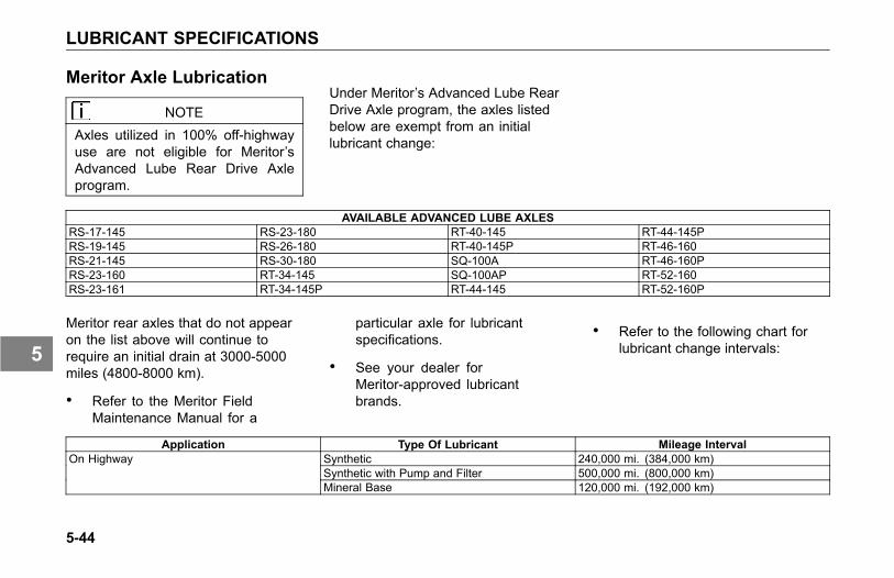
LUBRICANT SPECIFICATIONS
Meritor Axle Lubrication
NOTEAxles utilized in 100% off-highwayuse are not eligible for Meritor’sAdvanced Lube Rear Drive Axleprogram.
Under Meritor’s Advanced Lube RearDrive Axle program, the axles listedbelow are exempt from an initiallubricant change:
AVAILABLE ADVANCED LUBE AXLESRS-17-145 RS-23-180 RT-40-145 RT-44-145PRS-19-145 RS-26-180 RT-40-145P RT-46-160RS-21-145 RS-30-180 SQ-100A RT-46-160PRS-23-160 RT-34-145 SQ-100AP RT-52-160RS-23-161 RT-34-145P RT-44-145 RT-52-160P
Meritor rear axles that do not appearon the list above will continue torequire an initial drain at 3000-5000miles (4800-8000 km).
• Refer to the Meritor FieldMaintenance Manual for a
particular axle for lubricantspecifications.
• See your dealer forMeritor-approved lubricantbrands.
• Refer to the following chart forlubricant change intervals:
Application Type Of Lubricant Mileage IntervalSynthetic 240,000 mi. (384,000 km)Synthetic with Pump and Filter 500,000 mi. (800,000 km)
On Highway
Mineral Base 120,000 mi. (192,000 km)
5-44
5

LUBRICANT SPECIFICATIONS
Application Type Of Lubricant Mileage IntervalSynthetic 120,000 mi. (192,000 km)Synthetic with Pump and Filter 240,000 mi. (384,000 km)
City Delivery
Mineral Base 120,000 mi. (192,000 km)Synthetic 120,000 mi. (192,000 km)Synthetic with Pump and Filter 120,000 mi. (192,000 km)
Off Highway
Mineral Base 120,000 mi. (192,000 km)
• Change the lubricant filter every120,000 miles (192,000 km). Topoff the lubricant level with a similarlubricant.
Eaton/Dana Axle Lubrication• The original mineral-based
lubricant must be drained within3000-5000 miles (4800-8000km) on all Eaton axles. Thisinitial change is very importantbecause it flushes out break-incontaminants that might otherwisecause premature wear.
• No initial drain is required onEaton axles that are factory filledwith an Eaton-approved syntheticlubricant.
• Mineral-based lubes must bedrained within the first 5000 miles(8000 km) if converting to anEaton-approved synthetic lube.
• Change the lubricant within thefirst 5000 miles (8000 km) ofoperation after a carrier headreplacement, regardless of thelubricant type.
• Refer to the Eaton FieldMaintenance Manual for aparticular axle for lubricantspecifications.
• See your dealer forEaton-approved lubricant brands.
• Refer to the chart below forlubricant change interval.
5-45
5

LUBRICANT SPECIFICATIONS
Type of Lubricant On-Highway Mi. (km) Maximum Change Interval On/Off Highway SevereService Mi. (km)
Maximum Change Interval
Mineral-Based 120,000 (192,000) Yearly 60,000 (96,000) YearlyEaton-Approved Synthetic 240,000 (384,000) 2 Years 120,000 (192,000) YearlyEaton-Approved Syntheticin axle with extended draininterval option
350,000 (560,000)
Wheel Bearing LubricationOil-lubricated Driven Hubs
Use hypoid oil, A.P.I.-GL-5 SAE75W-90FE synthetic gear lubricantor equivalent. A minimum of 1 quart(921 ml) of oil is required for properlubrication of each drive hub. Add oilthrough the filler hole in the hub; ifnone, add oil through the differentialfiller hole. (Note: Remember to replacevent plug or threaded filler plug whendone.) Allow time for the oil to seepthrough the bearings when initiallyfilling a hub. Maintain the differentialoil level by adding oil until its surface iseven with the bottom of the filler hole(see illustration on page 5-37).
Oil-lubricated NondrivenHubs
Use CD50 synthetic transmission fluidSAE 50W or equivalent. A minimum of9 oz. (270 ml) of lubricant is requiredfor proper lubrication of an LMS™ hub;10-13 oz. (295-400 ml) is required fora non-LMS hub, depending on wheeldesign. Allow time for the fluid to seepthrough the bearings when initiallyfilling a hub. When properly filled, thefluid level will lie between the fluid levelline and 1/4” above the line.
NOTERemember to replace vent plugwhen done.
Universal Joint Lubrication
Refer to the Spicer Universal Jointsand Driveshafts service manual andlubrication specifications.
5-46
5
LUBRICANT SPECIFICATIONS
Steering Gear LubricationFluid Refill
The following recommendations arefor general purpose steering systems(both TRW and Sheppard).
• For normal temperatures, useAutomatic Transmission Fluid(ATF) Type E or F or Dexron® III.
• For cold temperatures of -22º F(-30º C) and above use ATF TypeA.
• For extremely cold temperaturesbetween -22º F (-30º C) and -40ºF (-40º C) use ATF Type B.
Inspection
NOTEBefore removing reservoir cover,wipe outside of cover so that no dirtcan fall into the reservoir.
1. Check the fluid level; add fluid ifrequired.
2. Check fluid for contamination,discoloration, or burnt smell;correct source of such problemsbefore replacing fluid & filter.
CAUTION
When adding fluid, be sure to usefluid of the same type. While manyfluids have the same descriptionand intended purpose, they shouldnot be mixed due to incompatibleadditives. Mixing incompatible fluidsmay lead to equipment damage.
If incompatible (insoluble) fluids aremixed in a power steering system,air bubbles can be produced at theinterface of the two fluids. This cancause cavitation, which reduces thelubrication between moving parts inthe gear. This could result in worncomponents.
The mixture of two different fluids,although harmless to individualinternal components, may initiate achemical reaction that produces a newcompound that will attack seals andother internal components.
Do not mix different fluids.
5-47
5

AIR SYSTEM
AIR SYSTEM
Introduction
WARNING
Do not attempt tomodify, alter, repairor disconnect any component of theair system. Repairs or modificationsto the air system, other than whatis described in this section, shouldonly be performed by an authorizeddealer. Failure to comply may resultin death or personal injury.
WARNING
Prior to the removal of any airsystem component, always blockand hold the vehicle by a securemeans other than the vehicle'sown brakes. Depleting air systempressure may cause the vehicleto roll unexpectedly resulting in anaccident causing death or personalinjuries. Keep hands away fromchamber push rods and slackadjusters, they may apply as systempressure drops.
WARNING
After completing any repairs tothe air system, always test for airleaks, and check the brakes forsafe operation before putting thevehicle in service. Failure to complymay result in death, personal injury,equipment or property damage.
WARNING
Never connect or disconnect a hoseor line containing air pressure. Itmay whip as air escapes. Neverremove a component or pipe plugunless you are certain all systempressure has been depleted. Failureto comply may result in death,personal injury, equipment orproperty damage.
WARNING
Never exceed recommended airpressure and always wear safetyglasses when working with airpressure. Never look into airjets or direct them at anyone.Failure to comply may result indeath, personal injury, equipment orproperty damage.
5-48
5

AIR SYSTEM
WARNING
Never attempt to disassemble acomponent until you have readand understood recommendedprocedures. Some componentscontain powerful springs andinjury can result if not properlydisassembled. Use only propertools and observe all precautionspertaining to use of those tools.Failure to comply may result indeath, personal injury, equipment orproperty damage.
WARNING
Completely bypassing a Bendix®AD-IS air dryer will bypass thesystem’s pressure protection valves.This could lead to loss of airpressure or damage to the vehicle’sair system, which could causean accident involving death orpersonal injury. Always adhere tothe manufacturer’s procedure if itis necessary in an emergency totemporarily bypass an AD-IS-seriesair dryer. Failure to comply mayresult in death, personal injury,equipment or property damage.
The operation of the vehicle’s brakingsystem and many vehicle accessoriesdepends upon the storage andapplication of a high-pressure airsupply.
Your vehicle’s compressor takesoutside air and compresses it, usuallyto 100-120 psi (689-827 kPa). The
compressed air then goes to thereservoirs to be stored until needed.When you operate your air brakes, thestored compressed air flows into thechambers where it is used to applyyour truck and trailer brakes. That iswhy, when you push down on yourbrake pedal, you don’t feel the sameamount of pressure on the pedal thatyou do when you apply the brakes onyour car. All you are doing on yourtruck is opening an air valve to allowair to flow into the brake chambers.
Contamination of the air supply systemis the major cause of problems inair-operated components such asbrake valves, and suspension heightcontrol valves. To keep contaminantsto the lowest possible level, followthese maintenance procedures.
5-49
5

AIR SYSTEM
WARNING
If the supply and service tanks arenot drained at the recommendedfrequency, water could enter theair lines and valves. This couldcause corrosion or blockage, whichcould compromise the brake systemsafety and potentially cause anaccident involving death or personalinjury.
Daily• Drain moisture from the supply
and service air tanks.
• Operate air devices to circulatelubricants within the unit.
Periodically• Clean filter screens ahead of the
valves by removing the screensand soaking them in solvent. Blowthem dry with pressurized airbefore reinstalling them.
5-50
5

AIR SYSTEM
Twice a Year• Maintain the air compressor to
prevent excessive oil by-pass.See your maintenance manual fordetails.
• Replace worn seals in valves andair motors as they are needed.
Air Dryer
The function of the air dryer is to collectand remove air system contaminants insolid, liquid and vapor form before theyenter the brake system. It providesclean, dry air to the components ofthe brake system, which increasesthe life of the system and reducesmaintenance costs.
NOTEBecause no two vehicles operateunder identical conditions,maintenance and maintenanceintervals will vary. Experience is avaluable guide in determining thebest maintenance interval for anyone particular operation.
Every 900 operating hours or 25,000miles (40,200 km) or every three (3)months check for moisture in the airbrake system by opening air tanks,
drain cocks, or valves and checking forpresence of water.
NOTEA small amount of oil in the systemmay be normal and should not,in itself, be considered a reasonto replace the desiccant cartridge.Oil stained desiccant can functionadequately.
A tablespoon of water found in theair tank would point to the need for adesiccant cartridge change. However,the following conditions can alsocause water accumulation and shouldbe considered before replacing thedesiccant cartridge.
• Air usage is exceptionally highand not normal for a highwayvehicle. This may be due toaccessory air demands or someunusual air requirement thatdoes not allow the compressorto load and unload (compressing
5-51
5

AIR SYSTEM
and non-compressing cycle) in anormal fashion or it may be due toexcessive leaks in the air system.
• In areas where more than a 30°F (17° C) range of temperatureoccurs in one day, small amountsof water can accumulate inthe air brake system due tocondensation. Under theseconditions, the presence of smallamounts of moisture is normaland should not be considered asan indication that the dryer is notperforming properly.
• An outside air source has beenused to charge the air system.This air did not pass through thedrying bed.
Overhaul
Maintenance intervals typical foron-highway operation would be 2 - 3years, 350,000 miles or 10,800 hours.
Maintenance intervals typical for highduty cycle usage such as transit bus,refuse hauler, dump truck, cementmixers and off-highway operationwould be 1 year, 100,000 miles or3,600 hours.
NOTEReview the warranty policy beforeperforming any maintenanceprocedures. An extended warrantymay be voided if unauthorizedmaintenance is performed duringthis period.
Bendix® AD-IS Series AirDryer
Your vehicle may be equipped with aBendix® AD-IS series air dryer. Anyair dryer replacement should be madewith an identical component.
WARNING
If a different air dryer brand or modelis installed on the vehicle otherthan what was originally installed,it could cause the air system tonot perform correctly unless thefull air system design is reviewedand modifications made to complywith Federal Motor Vehicle SafetyStandards (FMVSS) 121 - Air BrakeSystems. Failure to abide by thiswarning and maintain complianceto FMVSS 121 could cause lossof vehicle control and may lead todeath or serious personal injury.
5-52
5

AIR SYSTEM
The AD-IS Series air dryer hasincorporated into its design variouscomponents that have typically beeninstalled separately on the vehicle (seebelow for components/areas affected).
• Pressure protection valves
• Safety valve
• Governor and plumbing
• Plumbing of the front and rearservice air tanks
• Plumbing to accessory systems
These components are required tomeet the Federal Motor Vehicle SafetyStandards (FMVSS 121 - Air BrakeSystems). As the Warning abovestates, any other type of air dryerinstalled in the place of an AD-IS Serieswill require changes, modificationsand/or additions to your vehicle’s airsystem to maintain compliance withFMVSS 121.
Air Tanks
To eject moisture from the air systemtanks, pull the line that is connected tothe moisture ejection valve. Continuepulling until the air comes out free ofwater.
Daily: The supply and service airtanks, must be drained on a dailybasis. Operate air devices daily tocirculate lubricants within the unit.
Periodically: Clean filter screensahead of the valves by removing thescreens and soaking them in solvent.Blow them dry with pressurized airbefore reinstalling them.
WARNING
If the supply and service air tanksare not drained at the recommendedfrequency, water could enter theair lines and valves. This couldcause corrosion or blockage, whichcould compromise the brake systemsafety and potentially cause anaccident. Failure to comply mayresult in death, personal injury,equipment or property damage.
CAUTIONDo not use penetrating oil, brakefluid, or wax-based oils in the airsystem. These fluids may causesevere damage to air systemcomponents.
• Maintain the air compressor toprevent excessive oil bypass.
• Replace worn seals in valves andair motors as they are needed.
5-53
5

AIR SYSTEM
Your authorized dealer carriesrebuild kits for most units.
Air Gauges and Air Leaks
Your vehicle comes with air pressuregauges for two separate systems,Primary and Secondary: the Primarygauge indicates pressure in the rearbraking system; the Secondary gaugeindicates pressure in the front brakingsystem. Each gauge indicates theamount of air pressure in pounds persquare inch (psi).
WARNING
Do not operate the vehicle if leakagein the air system is detected.Conduct the following procedureand contact an authorized dealer(or any other properly equippedservice center) if a leak is detected.Failure to check the brakes or followthese procedures could cause asystem failure, increasing the riskof an accident and may result indeath, personal injury, equipment orproperty damage.
If the light and alarm do not turn off atstart-up, do not try to drive the vehicleuntil the problem is found and fixed. Ifthe pressure in either or both systemsis too low for normal brake operation,i.e., the pointer of one gauge fallsbelow 65 psi (448 kPa), a warning lighton the gauge will glow and the audiblealarm will sound.
NOTEPark brakes lock up at 60 psi (414kPa), the audible alarm will sound at65 psi (448 kPa).
Primary Air Pressure Gauge
5-54
5

AIR SYSTEM
Secondary Air Pressure Gauge
Follow the procedure below tocheck the compressed air systemfor leaks:
1. Periodically, or after maintenanceor replacement of air systemcomponents:
2. Build up air pressure in the systemto the governor cutout point or until120 psi (827 kPa) is reached.
3. Stop the engine and release theservice brakes.
4. Without applying the brake pedal,observe the rate of air pressuredrop. This rate should not exceed2.0 psi (14 kPa) per minute.
5. Start the engine and build up theair pressure again.
6. Stop the engine, and apply thebrakes fully. Apply the brake pedaland hold it down for five minutes.The pressure drop should notexceed 3.0 psi (21 kPa) perminute.
7. If you detect excessive leakage(air pressure loss greater than 3.0psi (21 kPa) after five minutes ofbrake application), a leakage testshould be made at the air lineconnections and at all air brakecontrol units. These tests shoulddetermine where air is escaping.
Air CompressorOperation
All compressors, regardless of makeor model, run continuously while theengine is running. System pressureis controlled by the governor. Thegovernor acts in conjunction withthe unloading mechanism in thecompressor cylinder block to startand stop compression of air. Thecompressor is unloaded when thesystem pressure reaches 120 psi (827kPa) and compression is reestablishedwhen system pressure falls to 100 psi(690 kPa).
5-55
5

AIR SYSTEM
Preventive Maintenance
The following service checks areprovided for your information only andshould be performed by a certifiedmechanic. Contact your dealer or theengine manufacturer's MaintenanceManual for further information onservicing air compressors.
After completing any repairs to the airsystem, always test for air leaks, andcheck the brakes for safe operationbefore putting the vehicle in service.
Below is a list of areas to maintain forthe air compressor:
• Inspect compressor air filterelement, if so equipped, andreplace element if clogged. Checkcompressor mounting and drivefor alignment and belt tension.Adjust if necessary.
• Remove compressor dischargevalve cap nuts and check for
presence of excessive carbon. Ifexcessive carbon is found, cleanor replace the compressor cylinderhead. Also, check compressordischarge line for carbon, andclean or replace the discharge lineif necessary.
• Disassemble compressor andthoroughly clean and inspectall parts. Repair or replaceall worn or damaged parts, orreplace compressor with a factoryexchange unit.
CAUTIONWhen draining the engine coolingsystem is required, to preventdamage from freezing, thecompressor must also be drained atthe cylinder head and block. Enginedamage could occur if the coolingsystem is not periodically drainedand maintained. See CoolingSystem on page 5-71 for furtherinformation.
5-56
5

BRAKE SYSTEM
BRAKE SYSTEM
Brake Adjustment
WARNING
Do not work on the brake systemwithout the parking brake set andwheels chocked securely. If thevehicle is not secured to preventuncontrolled vehicle movement, itcould roll and cause death, seriouspersonal injury or damage to thevehicle.
To operate your vehicle safelyand profitably, you need someunderstanding of its brake systems.For more on brakes, see the Index,under Brakes.
Brake adjustment and brake balancemust be set carefully to (1) makethe most efficient use of the forcesavailable for braking and (2) allowequal stopping forces at all wheels.
CAUTION
The air brake system of thisvehicle was configured for ONEof the following operations: tractoror truck, and complies with therespective portions of FMVSS 121.A tractor shall not be operated orconfigured as a truck, nor shall atruck be operated or configuredas a tractor, without significantmodifications to the air brake systemin order to retain compliance withFMVSS 121. Contact your dealerfor instructions.
Once a brake system is set tospecifications, changing any one ofits components or any combination ofcomponents may cause the systemto not work as well. All parts haveto work together to perform as theyshould. Any replacement componentsin your brake system should be exactlyequal to the original components.
Any changes from the originalspecifications can affect the wholesystem. All of the following areasare interrelated and must conform tooriginal specifications:
• Tire Size
• Drum brakes
a. Cam Radius
b. Wedge Angle
c. Drum Radius
d. Brake Linings
e. Brake Chambers
f. Slack Adjusters
• Disc Brakes
a. Disc Rotors
5-57
5

BRAKE SYSTEM
WARNING
Do not use any replacementpart in the brake system unlessit conforms exactly to originalspecifications. A nonconformingpart in your vehicle's brake systemcould cause a malfunction resultingin an accident causing death orpersonal injury. Sizes and typesare so related to one another thata seemingly unimportant change inone may result in a change in howwell the brakes work for you on theroad. If parts do not work togetherproperly, you could lose control ofyour vehicle, which could cause aserious accident.
All vehicle operators should checktheir brakes regularly.
WARNING
Do not use brake linings witha thickness below the specifiedminimum. Such linings will havelining rivets exposed that candamage the brake drum and reducebrake efficiency, which could causedeath, personal injury or systemfailure.
Air Disc Brakes
Have brake pads inspected by aqualified mechanic for wear at regularintervals according to the PreventiveMaintenance Schedule on page 5-12.In severe service or off-highwayapplications inspect the linings morefrequently.
Regularly inspect for pad/rotor wear:
• Park on level ground and chockthe wheels.
• Temporarily release the parkingbrakes.
• Compare the relative positionof two notches; one located onthe caliper and the other on thecarrier. See the illustration belowto determine if the brakes requirea detailed inspection by a qualifiedmechanic.
5-58
5

BRAKE SYSTEM
• Have a qualified mechanicperform a detailed inspectionif the notches are not found.The pads and rotors shouldbe measured and comparedagainst the manufacturersspecifications located in the brakemanufacturer’s service manual.
Caliper Detail
1. Brake Caliper Assembly2. Location of Inspection
Grooves3. Notches Line-Up (Time to
schedule inspection of Padsand Rotors)
4. Brake Rotor5. Brake Carrier Assembly
Regularly inspect caliper for RunningClearance:
• Stop the vehicle on level groundand let the brakes cool down. Hotbrake calipers can burn skin oncontact.
• Chock the wheels.
• Temporarily release the parkingbrakes.
• Grab the caliper and move it. Thismovement is Running Clearance.
• Proper Running Clearance is0.08 inch (2 mm) of movement ofthe brake caliper (approximatelythe thickness of a nickel) in theinboard/outboard direction.
• Have a qualified mechanic providefurther inspection if the caliperdoes not move or appears to movemore than the specified clearance.
5-59
5

BRAKE SYSTEM
Drum Brakes
Have brake drum linings and discbrake pads inspected by a qualifiedmechanic for wear at regular intervalsaccording to the maintenanceschedule. In severe service oroff-highway applications inspect thelinings more frequently.
Automatic Slack Adjusters
Periodically check the Brake ChamberStroke. Replace the slack adjuster ifproper stroke cannot be maintained.
Operational checks ofautomatic slack adjusters
• Measure brake chamber strokewith the spring brake released andthe air pressure no less than 100psi (690 kPa).
• Brake Chamber Stroke is thedifference between the appliedand the retracted position of theair chamber pushrod.
• A correctly installed andfunctioning auto slack adjuster willproduce the following strokes:
Chamber Type Stroke36 (rear brakes) 1-1/2” - 2-1/4”
(38 - 57 mm)30 (rear brakes) 1-1/2” - 2”
(38 - 51 mm)16, 20 & 24 (frontbrakes)
1” - 1-3/4”(25.4 - 44.4 mm)
Brake Chamber Stroke
5-60
5

BRAKE SYSTEM
WARNING
Manual adjustment of automaticslack adjusters is a dangerouspractice that could have seriousconsequences. It gives the operatora false sense of security aboutthe effectiveness of the brakes.Contact the Service Departmentat your dealership if the strokeexceeds the above specifications. Astroke exceeding these values mayindicate a problem with the slackadjuster or the brake foundation.
5-61
5

CAB
CAB
Exterior MaintenancePainted Surfaces
Wash painted surfaces frequently toremove grime and caustic depositswhich may stain the finish. SeeCleaning, Protecting, and WeatherStripping on page 5-63.
Chrome and AluminumSurfaces
To prevent rust, keep chromed partsclean and protected with wax at alltimes, especially in winter conditionswhere the roads are salted.
• If necessary, use a commercialchrome cleaner to remove lightrust.
• Chrome surfaces are bestcleaned with fresh water. Wipedry to preserve their luster. Acommercial chrome cleaner willremove light rust. After cleaning,wax flat surfaces and apply a thincoat of rust preventive lubricantaround bolts or other fasteners.
• Clean aluminum wheels andbumpers with warm water. Tarremover will get rid of heavydeposits of road grime. To preventspotting, wipe aluminum surfacesdry after washing.
• Under corrosive conditions, suchas driving on salted roads, cleanaluminum parts with steam or highpressure water from a hose. Amild soap solution will help. Rinsethoroughly.
5-62
5

CAB
Tail Pipe Surface Cleaning
WARNING
Always allow hot surfaces to cooldown before attempting to work nearthem. Failure to comply may resultin death or personal injury.
To maintain your quality finish, washwith a soft cloth, mild soap and wateror glass cleaner. A non-abrasivechrome polish (e.g. Windex®) can beused sparingly on hard to clean areas.Do Not clean your high heat chromeusing scouring pads, abrasive chromepolish, highly acidic chemical cleanersor any other abrasive cleaners.
Stainless Steel
Even high quality stainless steel partscan rust under prolonged exposureto salt water, especially when thesalt-laden moisture is held againstthe metal surface by road grime. Itis, therefore, important to frequentlyclean salty moisture and grime fromstainless steel surfaces.
• If surface rust is encountered,wash the surface and use acommercial polishing compoundto clean off the rust, followed by acoating of wax.
• Never use steel wool whencleaning stainless steel becauseminute particles of the steel woolcan embed in the surface of thestainless steel and cause ruststaining.
Cleaning, Protecting andWeather Stripping
Frequent washings of the vehicleare required to remove grime andcontaminants that can stain andoxidize paint and accelerate corrosionof plated and polished metal surfaces.
Waxing offers added protection againststaining and oxidation. But to allowenough time for your truck's finish tocure, wait about 30 days after the dateof manufacture before waxing. Do notapply wax in the hot sun and do notfriction burn the paint with a buffingmachine.
Occasionally spray weather-strippingon doors and windows with siliconecompound to help preserve resiliency.This is especially useful in freezingweather to prevent doors and windowsfrom sticking shut with ice.
5-63
5

CAB
Vehicle Cleaning
Precautions
WARNING
Handle cleaning agents carefully.Cleaning agents may be poisonous.Keep them out of the reach ofchildren. Failure to comply mayresult in death, personal injury,equipment or property damage.
WARNING
Do not use gasoline, kerosene,naphtha, nail polish remover or othervolatile cleaning fluids. They maybe toxic, flammable or hazardousin other ways. Failure to complymay result in death, personal injury,equipment or property damage.
WARNING
Do not clean the underside ofchassis, fenders wheel covers, etc.without protecting your hands andarms. You may cut yourself onsharp-edged metal parts. Failureto comply may result in death,personal injury, equipment orproperty damage.
WARNING
Moisture, ice, and road salt onbrakes may affect braking efficiency.Test the brakes carefully after eachvehicle wash. Failure to complymay result in death, personal injury,equipment or property damage.
• Observe all caution labels.
• Always read directions on thecontainer before using anyproduct.
• Do not use any solution that candamage the body paint.
• Most chemical cleaners areconcentrates which requiredilution.
• Only use spot removing fluids inwell ventilated areas.
• Any vehicle is subjected todeterioration from industrialfumes, ice, snow, corrosive roadsalt, etc., to name just a fewcauses. A well-cared-for vehiclecan look like new many yearslater. Regular and correct carewill contribute to maintaining thebeauty and the value of yourvehicle.
Your dealer has a number ofvehicle-care products and can adviseyou on which ones to use for cleaningthe exterior and interior of your vehicle.
5-64
5
CAB
CAUTIONDo not aim the water jet directly atdoor locks or latch. Tape the keyholes to prevent water from seepinginto the lock cylinders. Water in lockcylinders should be removed withcompressed air. To prevent locksfrom freezing in the winter, squirtglycerin or lock deicer into the lockcylinders.
Washing the Exterior1. Begin by spraying water over the
dry surface to remove all loose dirtbefore applying the car wash andwax solution.Do not wash the vehicle in directsunshine.Do not spray water directly into thecab vents.
2. Using soapy water, wash thevehicle with a clean soft cloth ora soft brush made for automotivecleaning.Use cool or warm water and amild, household type soap. Strongindustrial detergents and cleaningagents are not recommended.Do not use stiff brushes, papertowels, steel wool, or abrasivecleaning compounds becausethey will scratch painted, plated,and polished metal surfaces.
3. Rinse surfaces frequently whilewashing to flush away dirt that
might scratch the finishes duringthe washing operation.
4. Wipe everything dry with achamois to avoid water spots.To prevent water spotting, dry offthe cosmetic surfaces with a cleancloth or chamois.
5. Remove road tar with anautomotive type tar remover ormineral spirits.
6. After cleaning and drying, apply aquality automotive wax.
NOTETo allow enough time for your truck'sfinish to cure, wait at least thirty daysafter the date of manufacture beforewaxing.
• Do not apply wax in the hot sun.
• Never dust off dry surfaces with acloth because it will scratch thefinishes.
5-65
5

CAB
Cleaning the Chassis• Hose dirt and grime from the
entire chassis. Then, if an oilleak develops, you will be able todetect it easier.
• Corrosive materials used for iceand snow removal and dust controlcan collect on the underbody. Ifthese materials are not removed,accelerated corrosion (rust) canoccur on underbody parts such asfuel lines, frames, floor pan, andexhaust system, even though theyhave been provided with corrosionprotection.
At least every spring, flush thesematerials from the under body withplain water. Be sure to clean anyarea where mud and other debris cancollect. Sediment packed in closedareas of the frame should be loosenedbefore being flushed. If desired, yourdealer can do this service for you.
Cleaning Interior Vinyl andUpholstery• Wipe vinyl upholstery and lining
with a good commercial upholsterycleaner. Do not use acetone orlacquer thinner.
• Clean fabric upholstery withupholstery shampoo speciallyformulated for this purpose. Followinstructions on the container.
Safety Restraint System -Inspection
The seat belt system, includingwebbing, buckles, latches, andmounting hardware, endures heavyuse in heavy-duty vehicles, much morethan seat belt systems in passengercars. All users should be aware of thefactors contributing to this heavy useand reduced belt life.
WARNING
Failure to properly inspect andmaintain restraint systems canlead to injury or loss of life.Without periodic inspectionand maintenance to detectunsafe conditions, seat restraintcomponents can wear out or notprotect you in an accident.
5-66
5

CAB
Factors contributing to reducedseat belt life:
• Heavy trucks typically accumulatetwice as many miles as theaverage passenger car in a giventime period.
• Seat and cab movement in truckscauses constant movement of thebelt due to ride characteristicsand seat design. The constantmovement of the belt insidethe restraint hardware and thepotential for the belt to come incontact with the cab and othervehicle parts, contributes to thewear of the entire system.
• Environmental conditions, such asdirt and ultraviolet rays from thesun, will reduce the life of the seatbelt system.
Due to these factors, the three-pointsafety belt system installed in your
vehicle requires thorough inspectionevery 20,000 miles (32,000 km). Ifthe vehicle is exposed to severeenvironmental or working conditions,more frequent inspections may benecessary.
Any seat belt system that shows cuts,fraying, extreme or unusual wear,significant discoloration due to UV(ultraviolet) exposure, abrasion to theseat belt webbing, or damage to thebuckle, latch plate, retractor hardwareor any other obvious problem shouldbe replaced immediately, regardlessof mileage.
WARNING
It is important to remember thatany time a vehicle is involved in anaccident, the entire seat belt systemmust be replaced. Unexposeddamage caused by the stress of anaccident could prevent the systemfrom functioning properly the nexttime it is needed. Failure to complymay result in death or personalinjury.
5-67
5
CAB
Inspection Guidelines
Follow these guidelines wheninspecting for cuts, fraying, extremeor unusual wear of the webbing,and damage to the buckle, retractor,hardware, or other factors. Damage tothese areas indicates that belt systemreplacement is necessary.
WARNING
Replace the entire belt system(retractor and buckle side) ifreplacement of any one part isnecessary. Unexposed damageto one or more components couldprevent the system from functioningproperly the next time it is needed.Failure to comply may result in deathor personal injury.
1. Check the web wear in the system.The webbing must be closelyexamined to determine if it iscoming into contact with any sharpor rough surfaces on the seat or
other parts of the cab interior.These areas are typical placeswhere the web will experiencecutting or abrasion. Cuts, fraying,or excessive wear would indicatethe need for replacement of theseat belt system.
2. The pillar web guide (D-loop) isthe area where almost constantmovement of the seat beltwebbing occurs because ofrelative movement between theseat and cab.
3. Check the Comfort Clip for cracksor possible damage and check forproper operation.
4. Check buckle and latch for properoperation and to determine iflatch plate is worn, deformed, ordamaged.
5. Inspect the retractor web storagedevice, which is mounted on thefloor of the vehicle, for damage.The retractor is the heart of the
occupant restraint system and canoften be damaged if abused, evenunintentionally. Check operationto ensure that it is not locked upand that it spools out and retractswebbing properly.
6. If tethers are used, be sure theyare properly attached to theseat and, if adjustable, that theyare adjusted in accordance withinstallation instructions. Tethersmust also be inspected for webwear and proper tightness ofmounting hardware.
7. Mounting hardware should beevaluated for corrosion, and fortightness of bolts and nuts.
8. Check web in areas exposed toultraviolet rays from the sun. If thecolor of the web in these areas isgray to light brown, the physicalstrength of the web may havedeteriorated due to exposure to
5-68
5
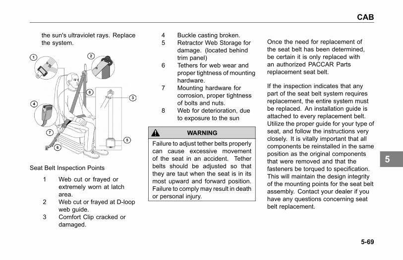
CAB
the sun's ultraviolet rays. Replacethe system.
Seat Belt Inspection Points
1 Web cut or frayed orextremely worn at latcharea.
2 Web cut or frayed at D-loopweb guide.
3 Comfort Clip cracked ordamaged.
4 Buckle casting broken.5 Retractor Web Storage for
damage. (located behindtrim panel)
6 Tethers for web wear andproper tightness of mountinghardware.
7 Mounting hardware forcorrosion, proper tightnessof bolts and nuts.
8 Web for deterioration, dueto exposure to the sun
WARNING
Failure to adjust tether belts properlycan cause excessive movementof the seat in an accident. Tetherbelts should be adjusted so thatthey are taut when the seat is in itsmost upward and forward position.Failure to comply may result in deathor personal injury.
Once the need for replacement ofthe seat belt has been determined,be certain it is only replaced withan authorized PACCAR Partsreplacement seat belt.
If the inspection indicates that anypart of the seat belt system requiresreplacement, the entire system mustbe replaced. An installation guide isattached to every replacement belt.Utilize the proper guide for your type ofseat, and follow the instructions veryclosely. It is vitally important that allcomponents be reinstalled in the sameposition as the original componentsthat were removed and that thefasteners be torqued to specification.This will maintain the design integrityof the mounting points for the seat beltassembly. Contact your dealer if youhave any questions concerning seatbelt replacement.
5-69
5

CAB
Windshield Wiper/Washer
The windshield wiper system ismaintenance free. Check wiper bladesannually or every 60,000 miles (96,000km).
Washer Reservoir
CAUTION
Do not use antifreeze or enginecoolant in the windshield washerreservoir, damage to seals and othercomponents will result.
Daily: Check reservoir water level,located in the engine compartment. Ifnecessary, refill to the proper level.
5-70
5

COOLING SYSTEM
COOLING SYSTEM
Cooling systemmaintenance
Your engine’s cooling system isstandard with Extended Life Coolant(ELC). ELC consists of a mixture ofethylene glycol, water, and organicacid technology chemical inhibitors.ELC prevents corrosion and scaleformation as well as provides freezingand boiling point protection.
CAUTIONThe engine cooling system hasvery specific maintenance andinspection requirements. Failure tofollow requirements can damage theengine. Engine damage can includebut is not limited to:
• Freezing
• Boiling
• Corrosion
• Pitted cylinder liners
This information is found in theengine manufacturers owner’smanual. It is the owner’sresponsibility to follow allrequirements listed in the enginemanufacturers owner’s manual.
What To Check In AnELC-filled Cooling SystemELC Concentration
Check the level of freeze/boiloverprotection, which is determined bythe ELC concentration. Use a glycolrefractometer to determine glycol level.Add ELC to obtain the ELC to waterratio required to provide the protectionyou need. Use the chart below to helpdetermine how much ELC you needto add.
NOTEMaximum recommended ELCconcentration is 60% ELC and40% water by volume (a 60/40coolant mixture). The minimumrecommended concentration is40%.
In an ELC-filled cooling system, thefreeze point should be maintained
5-71
5

COOLING SYSTEM
between -30° F and -45° F (-34° C and-43° C).
DesiredELC/Waterratio:
0% 10% 15% 20% 25% 30% 35% 40% 45% 50% 55% 60% 65% 70% 75% 80% 85% 90% 100%
Freezepoint °F(°C)
+32(0)
+25(-4)
+20(-7)
+15(-9)
+10(-12)
+5(-15)
-5(-21)
-12(-24)
-23(-31)
-34(-37)
-50(-46)
-65(-54)
-75(-59)
-84(-64)
-70(-57)
-55(-48)
-43(-42)
-30(-34)
-5(-21)
Items in bold are the recommended levels of concentration.
ELC Condition (Contaminationand Inhibitor Concentration)
Perform a visual inspection of theELC. It should have no cloudinessor floating debris. Determine thechemical inhibitor concentration levelby using an ELC-specific test kit ortest strips. Inhibitor concentration leveldetermines corrosion protection. If youare concerned about possible coolantquality, contamination, or mechanicalproblems, submit a coolant sample foranalysis. Improper maintenance maycause coolant degradation and couldresult in damage to the cooling system
and engine components. Consultyour dealer or the ELC manufacturer’srepresentative for recommended ELCtest kits, test strips, and laboratorysample procedures.
ELC Extender
Add ELC extender if necessary at themaintenance interval under “Cooling”.
Coolant Filter
If your vehicle came with anon-chemical filter (“blank filter”),replace it only with a blank filter at theinterval specified in the Preventive
Maintenance Schedule on page 5-12.Never use filters that contain SCAs inan ELC-filled system.
5-72
5

COOLING SYSTEM
Topping Off
WARNING
Removing the fill cap on a hot enginecan cause scalding coolant to sprayout and burn you badly. If the enginehas been in operation within theprevious 30 minutes, be very carefulin removing the fill cap. Protect face,hands, and arms against escapingfluid and steam by covering the capwith a large, thick rag. Do not try toremove it until the surge tank coolsdown or if you see any steam orcoolant escaping. In any situation,remove the cap very slowly andcarefully. Be ready to back off if anysteam or coolant begins to escape.
NOTEIf frequent topping off is necessaryand there are no visible signs ofcoolant leaks when the engine iscold, check for leaks with the engineoperating at normal temperature.
Top off the cooling system whencoolant does not rise to the levelindicated as ‘MIN’ on the surge tank.The surge tank is translucent whichallows the coolant level to be seen.Add coolant through the surge tank fillcap. Do not remove the pressure capto fill the cooling system.
Surge Tank
NOTEDo not use the pressure cap to fill thesurge tank with fluid.
Proper Coolant Level
NOTEDo not overfill a cooling system.Excess coolant may result inoverflow, loss of antifreeze, andreduced corrosion protection.
5-73
5

COOLING SYSTEM
• The minimum fluid level isdetermined by the line on thesurge tank indicated by the letters“MIN”. This indicator is locatedbelow the fill cap.
• The cooling system will need fluidif the surge tank level does not riseto the “MIN” line regardless if thesystem is hot or cold.
Refilling Your Radiator1. If your cooling system is built with
drain valves in the upper enginecoolant pipe, open them beforefilling the surge tank.
2. Close any open coolant drains inthe system.
3. Remove the surge tank fill cap(do not remove the surge tankpressure cap).
4. Fill the system with premixedcoolant through the surge tank fillcap. Pour coolant at a steady flow
rate until the surge tank is full (tothe base of the fill neck). It may benecessary to pause for 1 minuteand then re-fill if the fluid leveldropped.
5. Close any drain valves that wereopened in Step 1.
6. Start the engine and idle at lowRPM.
7. During low rpm idle, air will purgefrom the cooling system which willlower the coolant level in the surgetank. Continue to fill the surgetank until the coolant level remainsapproximately ½ in. above the"MIN" line. This may take up to 2minutes, depending on the outsidetemperature.
8. Operate the engine throttleuntil the operating temperaturestabilizes (when the thermostatopens).
9. Fill the surge tank as necessaryto raise the coolant level to ½ in.above the “MIN” level.
10. Operate the engine at high idle foranother 10 minutes and then fillthe surge tank again to ½” abovethe “MIN” level.
11. Replace the surge tank fill cap.
Check the coolant level after each trip.Add coolant as necessary. You mayfind your coolant level is not up to thecorrect level soon after you have filledthe radiator. This may be because allof the trapped air in the system has notyet been purged. It takes a little timefor all the air to leave the system afteryou fill your radiator.
5-74
5

COOLING SYSTEM
Engine (Block) Heater
WARNING
Do not use the heater if there areany signs of problems. Engineblock heaters can cause firesresulting in death, personal injury,equipment or property damageif not properly maintained andoperated. Regularly inspect theengine block heater wiring andconnector for damaged or frayedwires. Contact your authorizeddealer or the manufacturer of theheater if you are in need of repairsor information. Failure to complymay result in death, personal injury,equipment or property damage.
CAUTIONAlways unplug the block heaterbefore starting your engine.Damage to the cooling system couldoccur if not turned OFF (unplugged).
Use a solution of half ethylene glycolantifreeze and half water for bestheater performance. Do not usemore than 65 percent concentration ofantifreeze, as a shortened heater lifewill result.
After servicing the cooling system,operate the vehicle for a day or twobefore using the heater. Trappedair inside the engine needs time toescape.
5-75
5

ELECTRICAL
ELECTRICAL
Electrical System
WARNING
Battery posts, terminals and relatedaccessories contain lead and leadcompounds, chemicals known to theState of California to cause cancerand reproductive harm. Wash handsafter handling.
CAUTION
Do not modify or improperly repairthe vehicles electrical system orpower distribution box. All electricalrepairs should be performed byan authorized dealer. Improperrepair or modifications will voidyour warranty and/or cause seriousdamage to your vehicle.
Low Voltage Disconnect(LVD)
Purpose
The LVD may increase battery lifeand prevent unnecessary jumpstart conditions by ensuring that anunattended load does not depletethe battery charge to a level that willprevent you from starting your vehicle.
Operation
The LVD will disconnect non-vitalbattery loads when battery voltagedrops below 12.3V for 3 minutes andthe key switch is in the ACC or OFFposition. During the last 2 minutes theLVD will emit a slow audible beep. 30seconds before disconnecting loadsthe alarm will change to a fast beep.The battery voltage must come backup above a certain voltage before theLVD will reset.
See an authorized dealer if the LVDfails to reconnect loads during normaloperation.
Circuits Disconnected By LVD
• Cab Dome Lamps
• Cab Accessories
• Spare Battery A & B
NOTEAll LVD circuits are color-coded blueon the central electrical panel coverlabel.
5-76
5

ELECTRICAL
WARNING
Do not use the Spare BatteryA & B circuits or other circuitsthat are controlled by the LVD topower electronic engine controls,ABS circuits, or safety/work-relatedlighting. Before adding any deviceto the vehicle's electrical system,consult your nearest authorizeddealer or read the contents of TMCRP-136. Failure to do so maycause equipment damage or lead topersonal injury.
NOTEThe determination of whatcircuits/loads that were connectedto the LVD was based upon therecommendation from Technologyand Maintenance Council (TMC) ofthe American Trucking Association.To review the recommendedpractice, see TMC RP-136.
Light BulbsHeadlight Replacement
Replacing a headlight bulb isaccomplished by accessing the rearof the headlight via a access panel inthe front fender. Open the hood to getaccess to this panel.
Once the panel is open, the headlightbulb socket may be removed to replacethe bulb.
WARNING
Optional HID headlights have highvoltage circuits and should only beserviced by a trained technician.Attempting to service the HID ballastwithout proper training may result insevere electrical shock which couldlead to death or personal injury.
Access door
5-77
5

ELECTRICAL
Headlight Aiming
The headlights were properlyaimed at the factory to meet safetyspecifications. If the headlights need tobe adjusted, please have an authorizeddealership aim the headlights.
Bulb SpecificationsBulb Location Type of BulbLow Beam Halogen H11-LL (SAE), H7
(ECE) (long lifeversion not required)
Low Beam HID D1-SHigh Beam Halogen HB3A – LL (long life
version not required)Turn Signal/ DaytimeRunning Lamp
4157 NAK (SAE),PY27/7W (ECE)
Side Marker/PositionLamp/Park Lamp
168(SAE), W5W(ECE)
Rear tail light/ TurnSignal
Not applicable – LEDlighting
Interiormap/dome/indirectlight
Not applicable – LEDlighting
Fuses, Circuit Breakers andRelays
Fuses, circuit breakers, and relays arelocated in the Power Distribution Boxto the left of the steering column behindthe clutch pedal. Additional fuses arelocated in the engine compartment(drivers side bulkhead) and alsoin the sleeper under bunk storagecompartment.
5-78
5

ELECTRICAL
Engine Area Fuse Label
5-79
5

ELECTRICAL
In-Cab Fuse Label
5-80
5

ELECTRICAL
Sleeper Fuse Label
5-81
5

ELECTRICAL
Fuse Puller
Fuse Inspection andReplacement
If a fuse is blown, see What to do iffuse or relay blows on page 2-6 formore information.
Adding Electrical Options
WARNING
Do not add a fuse with a ratinghigher than 30 amps. Followthe circuit protection size/typerecommended by the componentmanufacturer. Installing a fuseor circuit breaker greater thandesignated may damage theelectrical system which could lead toequipment damage and/or personalinjury.
CAUTION
Follow all manufacturers' circuitprotection recommendations forthe components and wires beingadded. Failure to comply may resultin equipment damage.
5-82
5

ELECTRICAL
NOTEIf you are unfamiliar with properelectrical repair practices andprocedures, see your authorizeddealer for assistance.
NOTEEasy addition of circuits is providedby plug-in connectors that have aground and a power wire.
For proper electrical systemperformance, refer to a wiringdiagram for your chassis before addingelectrical options.
WARNING
Never install a circuit breaker in acircuit that is designated as “fuse-only” circuit(s). Fuse-only circuitsare marked with an * on the reverseside of the Power Distribution Boxcover. Using a circuit breaker inthose fuse-only circuits may causethe circuit to overheat when a shortexists which could lead to equipmentdamage and/or personal injury.
Batteries
Battery Access
The vehicle is originally equipped withthree or four batteries. Replacementbatteries must meet the followingspecifications: maintenance-free,group 31 size, threaded stud, 12V/ 650cold cranking ampere (CCA), and 160minutes of reserve capacity.
The battery compartment is located onthe left side of the vehicle, under thecab access steps.
1. Remove the 6 bolts that arelocated in the 2 cab access stepplate.
2. Remove battery cover for access.
5-83
5

ELECTRICAL
In-Cab Battery Box
Your vehicle may be equippedwith Absorbed Glass Mat (AGM)batteries located in the cab under thepassenger’s seat. The glass mat inAGM batteries are designed to absorbthe battery acid inside the battery thatcan leak or spill out in conventionalbatteries. This design feature allowsbatteries to be positioned in anyorientation without risk of leaking.
To access the batteries:
1. Remove 6 fasteners securing thepassenger side seat base to thebattery box assembly.
2. Remove the seat and seat baseas one unit to gain access to thebatteries.
WARNING
Replace only with AGM (Group 31)batteries. Use of other batteriescould result in acid leaks causingpersonal injury in the event of avehicle accident. Failure to complymay result in death, personal injury,equipment or property damage.
WARNING
Battery cables and air/electricalharnesses are mounted to thebottom of the floor. Do not drillor screw into floor pan withoutfirst checking the location of thecables, harnesses or any othercomponent that might be damaged.Damaging any component couldresult in electrical shock whichcould cause personal injury and/orloss of a critical truck system.Failure to comply may result indeath, personal injury, equipment orproperty damage.
WARNING
Electrical damage or batteryexplosion can occur whenimproperly charging batteries.Refer to the Charging System onpage 5-87 for appropriate charginginstructions. Failure to comply mayresult in death, personal injury,equipment or property damage.
5-84
5

ELECTRICAL
WARNING
Batteries release gases that areflammable. Batteries are equippedwith vent tubes and flash arrestorswhich vent battery gases out ofthe cab. Ensure all vent tubes,flash arrestors and grommets areproperly installed and ensure theyare clear and functioning properly.Failure to reinstall or keep thevent tubes and grommets clearor ensure the flash arrestor(s) arefunctioning properly could resultin personal injury or equipmentdamage. Failure to comply mayresult in death, personal injury,equipment or property damage.
CAUTIONDo not store other items in thisbattery box. Failure to comply couldresult in damage to the truck and/orbatteries.
CAUTIONProperly secure battery tie downsand battery box cover whenreinstalling batteries after service.Do not over tighten. Over tighteningcan crack the battery case whichcan lead to equipment damage.
Removing and InstallingBatteries:1. Be sure all switches on the vehicle
are turned OFF.
2. Disconnect negative ground cablefirst.
3. Disconnect positive cable.
4. Unscrew bolt of holding plate withopen end wrench.
NOTEAlways dispose of automotivebatteries in a safe and responsiblemanner. Contact your authorizeddealer for disposal standards. Callyour local authorized recyclingcenter for information on recyclingautomotive batteries.
Follow the procedure below to reinstallbatteries on the vehicle:
5-85
5

ELECTRICAL
NOTEMake sure to reconnect the ground(negative) cable last.
1. Place batteries in vehicle andtighten bolt of holding plate.
2. Reconnect positive cable.
3. Reconnect ground (negative)ground cable.
WARNING
Battery replacement may alteror disturb battery cable routing.Check to insure battery cables arefree from any point of chaffing.Failure to comply may result indeath, personal injury, equipment orproperty damage.
Replacing Parts Removedfor Access1. Replace battery cover.
2. Install 2 bolts in step strut. Torqueto 24-32 lb-ft (33-43 Nm).
3. Install fairing and install 4 bolts.Torque to 6-7 lb-ft (8-9 Nm).
4. Install steps by installing 2 bolts ineach step. Torque to 24-32 lb-ft(33-43 Nm).
WARNING
Always reinstall the steps beforeentering the cab. Without the stepsyou could slip and fall, resulting inpossible injury to yourself.
WARNING
Fairings not installed properlycould come loose and cause othermotorists to have an injury accident.It is important that fairings beinstalled properly. Failure to complymay result in death, personal injury,equipment or property damage.
WARNING
Before attempting any work onthe batteries or electrical system,remove all jewelry. If metal jewelryor other metal comes in contact withelectrical circuits, a short circuit mayoccur causing you to be injured, aswell as electrical system failure anddamage.
5-86
5

ELECTRICAL
Battery Care
Regular attention to the chargingsystem will help prolong the servicelife of the batteries. Here are somecommon causes of battery failure:
Overcharge: this condition resultsfrom improper voltage regulatoradjustment. It results in overheatingof the battery, warped plates, andevaporation of electrolyte.
Undercharge: the voltage regulatoris malfunctioning, the drive belt isslipping, or your vehicle has undergonelong periods of standing idle or shortdistance driving. These conditionsresult in battery plates becomingcovered with a hard coating.
Vibration: loose battery hold-downsmay cause battery plate failure.
Short Circuits: these discharge thebattery by draining electricity.
Dirty or Loose Connections:improper connections may stop theflow of electrical power to and from thebattery.
Battery Charging
Except for using small trickle chargesto maintain battery condition, youshould have your vehicle's batteriescharged by a qualified service facility.
WARNING
Batteries can injure you severely.They contain acid, producepoisonous and explosive gases, andsupply levels of electric current highenough to cause burns. A sparkor flame near a battery on chargemay cause it to explode with greatforce. Never remove or tamper withthe battery caps. Failure to complymay result in death, personal injury,equipment or property damage.
To help reduce the risk of personalinjuries, follow these guidelinescarefully when recharging a battery:
• Before attempting any servicein the electrical installation,
5-87
5

ELECTRICAL
disconnect the battery negativecable.
• Allow no sparks or open flameanywhere near the charging area.
• Charge a battery only in awell-ventilated area, such asoutdoors or in a fully open garagewhich contains no pilot lights orother flames. Gases generatedduring the charging process mustbe allowed to escape.
• Always make sure the batterycharger is OFF before connectingor disconnecting the cable clamps.
• To avoid short circuits, damageto the vehicle, or personal injury,never place metal tools or jumpercables on the battery or nearby.Metal that accidentally comes incontact with the positive batteryterminal or any other metal on thevehicle (that is in contact with the
positive terminal), could cause ashort circuit or an explosion.
Charging Reminders• Use protective eyewear.
• Keep all batteries away fromchildren.
• Never reverse battery poles.
• Never attempt to place the vehiclein motion, or run the engine withbatteries disconnected.
• Keep the battery clean and dry.
• Look for any signs of damage.
• Battery terminals should notbe coated with impropergrease. Use petroleum jellyor commercially available,noncorrosive, nonconductiveterminal coatings.
• Never use a fast charger as abooster to start the engine. Thiscan seriously damage sensitiveelectronic components such
5-88
5

ELECTRICAL
as relays, radio, etc., as wellas the battery charger. Fastcharging a battery is dangerousand should only be attempted bya competent mechanic with theproper equipment.
Slow Battery Charging
NOTEFollow the instructions that comewith your battery charger.
• It is not necessary to remove thebattery from the compartment.
WARNING
Charger cables must be connectedpositive to positive (+ to +) andnegative to negative (- to -). Ifconnected improperly, batteriescould explode. Failure to complymay result in death, personal injury,equipment or property damage.
WARNING
Always make sure the batterycharger is OFF before connectingor disconnecting the cable clamps.To reduce the danger of explosionsand resulting death or personalinjury, do not connect or disconnectcharger cables while the charger isoperating.
1. Disconnect the battery cables.
2. Connect charger cables.
3. Start charging the battery at a ratenot over 6 amperes. Normally, abattery should be charged at nomore than 10 percent of its ratedcapacity.
4. After charging, turn OFF chargerand disconnect charger cables.
5-89
5

ELECTRICAL
Electrical and AlternatorPrecautions
Take the following precautions toavoid burning out alternator diodes:
• Do not start the enginewith alternator disconnected(connections removed) from thecircuit.
• Before welding, disconnect allelectronic connections to thevehicle batteries.
• Remove battery power cable andinsulate it from the vehicle.
• Do not run the engine with thebatteries disconnected.
• Do not disconnect the batterycables or alternator connectioncables with the engine running.
• Never turn the ignition switch fromthe ON position to the STARTposition with the engine running.
• When charging the battery(installed in the vehicle) disconnectthe battery cables.
• Do not reverse the cables of thealternator, starter motor, or battery.
• Do not polarize the alternator. Thealternator should not be polarizedlike a generator. To ensure correctpolarity, use a test lamp or avoltmeter.
Remote Keyless Entry
The remote keyless entry system maybecome inoperational due to a keyfob battery. If you have issues witha key fob, replace the battery andre-synchronize the key fob. In somesituations, the key fob may need tobe replaced and in others, a fuse mayhave failed and may render both keyfobs inoperative.
Contact your dealer for more help ifa key fob does not work and it is notbecause of a bad battery.
5-90
5

ENGINE
ENGINE
Engine Maintenance
WARNING
Exhaust fumes from the enginecontain carbon monoxide, acolorless and odor less gas. Donot breathe the engine exhaustgas. A poorly maintained, damagedor corroded exhaust system canallow carbon monoxide to enter thecab. Entry of carbon monoxide intothe cab is also possible from othervehicles nearby. Failure to properlymaintain your vehicle could causecarbon monoxide to enter the caband cause death or personal injury.
WARNING
Never idle your vehicle for prolongedperiods of time if you sense thatexhaust fumes are entering the cab.Investigate the cause of the fumesand correct it as soon as possible.If the vehicle must be driven underthese conditions, drive only with thewindows open. Failure to repairthe source of the exhaust fumesmay result in death, personal injury,equipment or property damage.
NOTEKeep the engine exhaust systemand the vehicles cab ventilationsystem properly maintained. It isrecommended that the vehiclesexhaust system and cab beinspected:
• By a competent technician every15,000 miles
• Whenever a change is noticed inthe sound of the exhaust system
• Whenever the exhaust system,underbody or cab is damaged
5-91
5
ENGINE
Engine Lubrication
Refer to the engine manufacturer'sEngine Operation and MaintenanceManual supplied with your vehicle forinformation about draining and refillingengine oil, engine crank case capacity,engine oil type, and changing oil filters,etc.
WARNING
Hot engine oil can be dangerous.You could be burned. Let the engineoil cool down before changing it.Failure to comply may result indeath, personal injury, equipment orproperty damage.
Inspection of the Engine OilLevel
NOTEIt takes approximately 15 minutesfor all the oil to run into the sumpwhen the engine is ‘warm.’ If thelevel is checked immediately afterswitching off the engine, the dipstickwill show a low oil level.
1. Make sure that the vehicle framerail is standing on a flat and levelsurface.
2. Make sure that the vehicle ishorizontal, both lengthwise andcrosswise. Check this carefullyon a vehicle with air suspension.Note that the engine may beinclined up to 4° depending on thevehicle model and wheelbase.
3. Twist the dipstick handle to unlockit, then pull the dipstick out of theholder.
4. Wipe the dipstick clean with alint-free cloth.
5. Place the dipstick back into theholder.
6. Pull the dipstick out again andcheck the oil level. The oil levelshould always be between the 2marks on the dipstick.
5-92
5

ENGINE
7. Reinstall the dipstick and twist tolock it in place.
1. Engine Oil High Level2. Engine Oil Low Level
Topping Up the Engine Oil1. Top up with oil, if necessary, via
the filler opening. Use the correctgrade in the correct quantity. Foroil replacement, please see engineOperator’s Manual included withthis chassis.
2. After topping up, wait 1 minute andcheck the oil level again.
3. Reinstall the oil fill cap and twistto lock it in place.
Pipe and Hose Clamps
Use the following table for torquespecifications to check pipe and hoseclamps.
5-93
5

ENGINE
Pipe and Hose Clamp Torque Values
TORQUEAPPLICATION APPROVED CLAMPNm Lb-In
Radiator & Heat Exchanger Hoses Constant-Torque CT-L 10.2-12.5 90-110Heater Hoses Constant Tension not required not requiredAir Intake Pipes Hi-Torque HTM-L 11.3-14.2 100-125
Flex Seal 667 7.9-11.3 70-100Charge Air Intake HosesB9296 6-7 50-60
Fuel, Oil & Water Heat Exchangers (forhoses less than 9/16 diameter)
Miniature 3600L 1.1-1.7 10-15
Exhaust Clamps Breeze V-Band 54 480
5-94
5

ENGINE
Accessory Drive Belts
You can extend the reliability andservice life of your vehicle's drive beltswith proper attention to installation,and maintenance. Neglect couldcause belt failure. The result could bethe loss of the electrical or air systemas well as possible engine damagefrom overheating. So it's a very goodidea to check your belts frequently andreplace them as soon as you detecttrouble.
Follow this procedure to install anaccessory drive belt:
1. Route the new belt around thepulleys, and then rotate theautomatic tensioner so that theidler pulley swings toward thebelt routing. The following figureshows an example of the rotationdirection to release the tensioner.
2. Slip the belt around the idlerpulley attached to the automatictensioner.
3. Release the automatic tensioner.
4. Check the belt alignment on eachpulley. The belt must fall betweenthe flanges of each pulley.
Cummins Belt Routing
PACCAR MX Belt Routing
5-95
5
ENGINE
Engine Fan
WARNING
Do not work on the fan with theengine running. The engine fan canengage at any time without warning.Before turning on the ignition, besure that no one is near the fan.Failure to comply may result in deathor personal injury.
Your truck may be equipped with anOn/Off or Viscous Fan Drive. Followthese guidelines to check your enginefan:
Check the fan bearings for fan hubbearing looseness, loss of lubricantand any abnormal conditions. (Forexample, fan belt misaligned orexcessive wear/damage.) Beforestarting the engine and with the engineoff, look and feel for looseness in thefan hub.
With the engine idling and the hoodopen, stand at the front of the vehicle.Listen for any noises coming fromthe fan hub. Bearings that have lostlubricant, and are dry, will typically emita squeal or a growl when the engine isat operating temperature and the fanclutch is engaged. If noise is detected,have the fan bearings inspected by anauthorized dealership.
Fan Drive and Blade
WARNING
Do not work on the fan with theengine running. The engine fan canengage at any time without warning.Before turning on the ignition besure that no one is near the fan.Failure to comply may result in deathor personal injury.
Fan Blade Clearance: Around the fanshroud, the recommended distanceis 1 in. (25 mm) from front edge ofany fan blade-to-radiator side member.Minimum clearance is 3/4 in. (19 mm).
• Rear edge of any blade must beno closer than 3/8 in. (9 mm) tothe nearest engine component. Ifthis cannot be obtained, the fanspacer or fan is not correct.
• The leading edge of any fan blademust be 1 in. (25 mm) from theinside edge of the shroud.
5-96
5

ENGINE
Air Intake System
Engine heat, vibration, and agecombine to loosen air intakeconnections and cause cracks inthe tubing and elbows. Leaks in theintake system allow abrasive dust toenter the engine and quickly causeexpensive damage. During your dailywalk-around inspection, carefullycheck all tubing, elbows, clamps,supports and fasteners for conditionand tightness.
• Check the Charge-Air-Cooler forair leaks annually. The air leakscan be caused by cracked tubesor header. For service see yourauthorized dealer.
CAUTIONDo not use air intake pipes andconnections as a step or to pullyourself up. This could loosen theconnections and open the system tounfiltered air which could damagethe engine.
Turbocharger
When servicing the air intake andexhaust systems on a turbochargedengine, check the items listed below.
WARNING
Do not operate engine withturbocharger intake pipingdisconnected. A suction is createdwhen the engine is running. Thissuction could draw your hand oranything else near it into the impellerfan. You could be injured. Alwayskeep the intake piping connectedwhen you will be running the engine.
Lubricating System: Check the oillines, housing, and connections. Lookfor leaks, damage, or deterioration.Leaks could mean you have damagedoil lines or oil seals.
Manifold: With the engine operating,check for leaking manifold or flangegaskets.
5-97
5

ENGINE
High Frequency Vibration: Vibrationmay indicate turbo rotor imbalance.Have your dealer investigate thisimmediately. If you detect anydeficiencies, take the vehicle to anauthorized dealer for servicing. Delaycould lead to severe and expensivedamage to your vehicle.
Air Cleaners
The following service information isbasic to all air cleaner makes andmodels.
CAUTION
Failure to replace air filter at properintervals may result in passage ofdirt/debris into the engine or the“dusting” of an engine resulting insignificant engine damage.
Service the air cleaner filter elementsas specified in the PreventiveMaintenance Schedule on page 5-12.If your vehicle is equipped with anoptional air inlet restriction indicator,service the filter elements when the airinlet restriction indicator locks in theextreme Up position. Paper elementsrequire care and proper handlingbecause they are critical to engineservice life. If your vehicle has anexternal air cleaner and cab-mounted
mirrors, the mirror must be pivoted toprovide access for servicing the filterelement.
5-98
5

ENGINE
Replacing the Engine AirIntake Filter1. Open hood.
2. Loosen a total of 4 screws.(screws will not come out of thehousing)
3. Remove lid.
4. Remove filter.
Filter Minder
The Filter Minder is installed on the aircleaner or air induction piping so it hasaccess to clean filtered air. As the filterplugs and restriction increases, theyellow position indicator moves intothe clear window and locks at severalpoints. When it reaches the red zone,the air filter should be replaced. Theindicator can be reset by pressingthe yellow button at the end of theindicator.
Exhaust System
The exhaust system is part of thenoise and emission control system.Periodically check the exhaust forwear, exhaust leaks, and loose ormissing parts. For details see Noiseand Emission Control on page 5-115.
Please refer to the ExhaustAftertreatment operator manualfor more details on how to maintain theemission's components in the exhaustsystem.
5-99
5
FUEL SYSTEM
FUEL SYSTEM
Location of Fuel Shut-offValves
Fuel shut-off valves for the fuelcrossover line are on the bottom of thesecondary fuel tank, at the crossoverline connection. They are optional onthe primary fuel tank.
Specification
Use only diesel fuel as recommendedby engine manufacturers.
WARNING
A mixture of gasoline or alcohol withdiesel fuel in the presence of anignition source (such as a cigarette)could cause an explosion resultingin death or personal injury. Use onlythe recommended diesel fuel.
CAUTION
If anyone ever pours gasoline intoyour fuel tank, drain the entiresystem. Otherwise, the pump andengine will be damaged. Don’t try todilute the gasoline by adding dieselfuel (See Warning above).
Fuel Filters
Please follow these recommendationswhen you are changing your fuel filtersor strainer elements. Your enginewill run better and last longer if youdo. See the engine manufacturer’srecommendations for proper water andmicron requirements.
• When removing filters, cover anyelectrical equipment and wiringthat might get soaked with fuel.Diesel fuel may permanentlydamage electrical insulation.
• When installing spin-on(throwaway) filters, hand tightenthem only to 1/2 to 2/3 turn aftergasket contact. Over-tighteningthese filters may distort or crackthe filter head.
5-100
5
FUEL SYSTEM
NOTETo expel air from density-typestrainer elements, soak them inclean fuel before installing them.
• When replacing a fuel filterelement, don’t use a substitute.Install only filter elements designedfor fuel filtration. First clean andinspect the shell. Then insert thenew element and fill the containerat least 2/3 full of clean fuel beforeinstalling the shell.
• Throw away old gaskets. Replacethem with new ones to ensure apositive seal.
• Position the shell and gasketproperly. Then tighten the covernut or bolt just enough to preventfuel leakage.
• After starting the engine, check forleaks around the filter.
5-101
5

FRAME
FRAME
Introduction
WARNING
Do not cut, splice or weld framerails or drill through the top orbottom flanges of the rails. Theseoperations could affect frame railstrength leading to a failure resultingin an accident. Rail failures resultingfrom such modifications are notwarrantable. Failure to complymay result in death, personal injury,equipment or property damage.
Emergency Welding
WARNING
Frame welding is NOTrecommended. The high heatof welding nullifies the specialheat treatment of the rails, greatlyreducing the tensile strength ofthe frame rail. If a frame memberbecomes cracked from overloading,fatigue, surface damage or acollision, the only permanent repairis to replace the damaged framemember with a new part.
In an emergency, a temporary repairmay be performed. Observe thefollowing precautions to protectelectronic systems during weldingoperations. Emergency weldingprocedures are further explained in themaintenance manuals. Please refer tothe ordering information on the backcover to obtain a maintenance manual.
Welding Precautions
In the event of emergency welding of aframe rail and when welding any otherpart of your truck or any componentattached to your truck, observe thefollowing precautions before welding:
• Disconnect all electronic devices.It is not possible to list all of theelectronics that could be affected,but a few examples include thefollowing: alternator, engineElectronic Control Unit (ECU),transmission ECU, ABS ECU,navigation devices, diagnosticdevices, and monitoring devices.
• Disconnect battery cables andinsulate them from the vehicle.
• Do not use the ECU or engineground stud for the ground of thewelding probe.
• Ensure that the ground connectionfor the welder is as close to the
5-102
5

FRAME
weld point as possible. Thisensures maximum weld currentand minimum risk to damageof electrical components on thevehicle.
Painting
Do not electrostatically paint yourtruck or any component on yourtruck without first removing all ofthe electronic components from thetruck. It is not possible to list all ofthe electronics that could be affected,but a few examples include thealternator, engine Electronic ControlUnit (ECU), transmission ECU, ABSECU, navigation devices, diagnosticdevices, and monitoring devices.
Fifth Wheel Maintenance
Proper preventive maintenance isessential to trouble-free service andsafe operation of the fifth wheel.
Every 15,000 miles or monthly:
• Refer to specific manufacturer'sliterature for any specialinstructions.
• Steam clean the fifth wheel.
• Check lock guard operation usinga commercial lock tester.
• Clean and oil all moving parts.
• Lubricate the lock mechanism witha lithium-base grease.
• All grease fittings (especially thosewhich grease the top surface ofthe fifth wheel).
5-103
5

FRAME
Every 60,000 miles or 6 months:
• Refer to specific manufacturer'sliterature for any specialinstructions.
• Remove fifth wheel from vehicle.Refer to the Shop Manual, “FifthWheel Removal.”
• Steam clean the fifth wheel andmounting brackets.
• Check all moving parts forexcessive wear or damage.Replace all worn or broken parts.
• Complete two-month serviceprocedure.
• Install fifth wheel. Refer tothe Shop Manual, “Fifth WheelInstallation.”
Frame Fastener TorqueRequirements
Tighten all frame fasteners with atorque wrench. Torque specificationsapply to the following fasteners withlightly lubricated threads.
NOTEWhenever possible, torque all framefasteners on the nut end, not the bolthead.
Standard Grade 8 UNF or UNC and Metric
TORQUE *FASTENERSIZE Nm Lb-Ft5/16 22-30 16-223/8 41-54 30-407/16 75-88 55-651/2 109-122 80-909/16 156-190 115-1405/8 224-265 165-1953/4 394-462 290-3407/8 517-626 380-4601 952-1,129 700-830
1-1/8 1,346-1,591 990-1,1701-1/4 1,877-2,217 1,380-1,630
METRIC WITH NYLON INSERT NUTSM5 8-12 6-9M6 9-15 7-11M8 23-31 17-23M10 33-43 24-32M12 75-101 55-75M16 163-217 120-160M20 352-460 260-340
* ESNA Style Lock Nut, with nylon insert.Lubricate nylon insert nut lightly with SAE20/30 oil.
5-104
5

FRAME
Sliding Fifth Wheels
Lubricate bearing surface of supportbracket through the grease fittings onthe side of the fifth wheel plate. Use awater resistant lithium-base grease.
NOTEThe plate must be lifted up slightlyto relieve the weight of the bracketwhile applying grease.
5-105
5

FRONT AXLE AND SUSPENSION
FRONT AXLE ANDSUSPENSION
Axle Lubrication
Change bearing lubrication when sealsare replaced, or brakes are relined.See Preventive Maintenance Scheduleon page 5-12.
Thoroughly clean hubs and bearingswith solvent and a stiff bristle brush,then dry and inspect components forwear or damage. Re-lubricate withapproved axle lubricant.
Kingpin Lubrication
Lubricate with approved lubricant.Lubricate knuckle thrust bearings,knuckle pins, and tie rod ends. SeePreventive Maintenance Scheduleon page 5-12. Lack of lubricationcauses premature wear and hardsteering. Lubrication schedule may beshortened if necessary.
Suspension Lubrication
Each standard spring anchor pinhas a grease fitting. Pressurelubricate spring pins as specified. SeePreventive Maintenance Schedule onpage 5-12.
At regular intervals, the spring leavesmay be lubricated with a rust-inhibitingoil applied with a spray gun or brush.
Depending on your suspension,lubricate all spring pins until greaseflows out of both ends of the bushing.Look for signs of rust or water in theflushed grease. If a pin will not acceptgrease, it should be removed, cleaned,and inspected.
CAUTIONDo not spray the suspension withchemical products or mineral oil; itcan cause damage to the bushings.
5-106
5

FRONT AXLE AND SUSPENSION
Inspection
For all vehicles, mandatorymaintenance procedures includeretightening all U-bolts and inspectingthe suspension for loose fasteners,abnormal wear, or damage. However,even with proper maintenance, theservice life of leaf springs is affectedby many factors, such as: fatigue,vehicle gross weight, type of load, roadconditions, and vehicle speed.
Check for cracks, wear marks, splits,or other defects on the surface ofthe spring. Defective parts must bereplaced. Because repaired springscannot be fully restored to their originalservice life, replace the completeassembly if cracks or other defects aredetected.
Visually inspect shock absorbers andrubber bushings.
Wheel Alignment
For driving safety and comfort, andto prolong the life of your vehicle, itis important to have wheels correctlyaligned. Check tire wear frequently.Uneven tire wear is a sign that thewheels may be misaligned.
If you see uneven wear, take yourvehicle to an authorized dealer familiarwith aligning wheels on your vehicle.
5-107
5

FRONT AXLE AND SUSPENSION
U-Bolt Torque
It is important that U-bolts remain tight.Severe use of your vehicle will causethem to loosen faster. But all vehiclesneed to have their U-bolts checked andtightened regularly. Be sure someonewith the proper training and the righttools checks and tightens the U-boltson your vehicle.
New springs can settle in after service,relieving the tension on the U-bolts.Loose U-bolts can cause leaf springbreakage, axle misalignment, hardsteering and abnormal tire wear.
All vehicles should have suspensionU-bolts tightened after the first 500miles (800 km) of operation. Re-torquethe front spring pinch bolts and shacklepinch bolts.
WARNING
Do not operate the vehicle if theU-bolts are not properly tightened.Loose U-bolts will cause the axleto not be properly secured to thesuspension, which could causeloss of vehicle control and anaccident. Loose U-bolts can alsocause uneven tire wear and pooralignment. Failure to comply mayresult in death, personal injury,equipment or property damage.
U-bolts are difficult to tighten unlessyou have the right equipment. If youcannot tighten them correctly yourself,be sure to have them checked andtightened regularly by an authorizedmechanic.
Tighten U-bolt nuts to the specifiedtorque value with the vehicle loaded toits normal gross weight. The followingtorque values apply to U-bolts andnuts with clean threads lubricated with
Chevron zinc lubricant (SAE 20 or 30oils acceptable but not preferred).
WARNING
Do not replace U-bolts and nutswith common U-bolts or standardnuts. These parts are critical tovehicle safety. If the wrong U-boltsor nuts are used, the axle couldloosen or separate from the vehicleand cause a serious accident.Use only U-bolts and nuts of SAEGrade 8 specification or better.Failure to comply may result indeath, personal injury, equipment orproperty damage.
5-108
5

FRONT AXLE AND SUSPENSION
Front Spring Suspension U-Bolts, Grade 8
TORQUEU-BOLT SIZEDIAMETER(InchDimensions)
Nm Lb-Ft
3/4 333-408 245-3007/8 598-734 440-5401 925-1,060 680-780
1-1/8 1,470-1,660 1,080-1,2201-1/4 1,890-2,120 1,390-1,5601-1/2 3,130-3,860 2,300-2,840
5-109
5

HEATER AND AIR CONDITIONER
HEATER AND AIRCONDITIONER
Introduction
The combination heater-air conditionerprovides comfort for those in the cabthrough accurate control of the cabenvironment in all weather conditions.Regular attention to the items belowwill help you keep the heater-airconditioner unit running well.
Keep the vehicle's ventilation system,engine exhaust system and cabjoints properly maintained. It isrecommended that the vehicle'sexhaust system and cab be servicedas follows:
• Inspected by a competenttechnician every 15,000 miles
• Whenever a change is noticed inthe sound of the exhaust system
• Whenever the exhaust system,underbody or cab is damaged
To allow for proper operation of thevehicle ventilation system, proceed asfollows:
• Keep the inlet grille at the base ofthe windshield clear of snow, ice,leaves and other obstructions atall times.
• Keep the exhaust pipe area clearto help reduce the buildup ofexhaust gas under the vehicle.
• Check the drain tube of the freshair inlet for trapped water beforeassuming that there is a leak in theheating system.
Special Precautions
WARNING
Excessive heat may cause thepressurized components of the airconditioning system to explode.Never weld, solder, steam clean,or use a blow torch near any partof the air conditioning system.Failure to comply may result indeath, personal injury, equipment orproperty damage.
WARNING
Air conditioning refrigerant canbe hazardous to your health. Donot expose yourself to leakingrefrigerant for prolonged periodsnear excessive heat, open flames,or without proper ventilation. Failureto do so may result in death orpersonal injury.
If a refrigerant leak develops in thepresence of excessive heat or an
5-110
5

HEATER AND AIR CONDITIONER
open flame, hazardous gases may begenerated. If you become aware of arefrigerant leak on your vehicle haveyour system serviced immediately andobserve the following precautions:
Stay away from the hot engine until theexhaust manifold has cooled.
Do not permit any open flame in thearea. Even a match or a cigarettelighter may generate a hazardousquantity of poisonous gas.
Do not smoke in the area. Inhalinggaseous refrigerant through a cigarettemay cause violent illness.
Air FiltersCabin Fresh Air Filter
The fresh air filter for the cab HVAC islocated in the air intake housing that islocated in the passenger rear corner ofthe engine compartment. The filter canbe replaced without using any tools.
1. Tilt the hood open.
2. Locate air intake housing atpassenger rear corner of vehicleunder the rain tray.
3. Locate filter cover labeled “OPEN”with an arrow pointing rearward invehicle. Slide filter cover rearwardin vehicle until you are able toremove the cover.
4. Remove and inspect filter referringto maintenance interval schedule.
5. Replace filter in housing takingcare to align the airflow directionthat is indicated on the side of
5-111
5
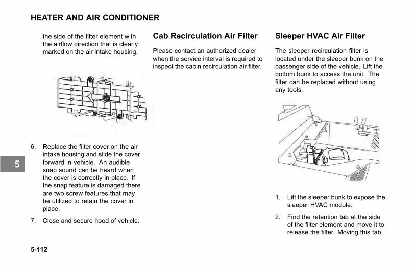
HEATER AND AIR CONDITIONER
the side of the filter element withthe airflow direction that is clearlymarked on the air intake housing.
6. Replace the filter cover on the airintake housing and slide the coverforward in vehicle. An audiblesnap sound can be heard whenthe cover is correctly in place. Ifthe snap feature is damaged thereare two screw features that maybe utilized to retain the cover inplace.
7. Close and secure hood of vehicle.
Cab Recirculation Air Filter
Please contact an authorized dealerwhen the service interval is required toinspect the cabin recirculation air filter.
Sleeper HVAC Air Filter
The sleeper recirculation filter islocated under the sleeper bunk on thepassenger side of the vehicle. Lift thebottom bunk to access the unit. Thefilter can be replaced without usingany tools.
1. Lift the sleeper bunk to expose thesleeper HVAC module.
2. Find the retention tab at the sideof the filter element and move it torelease the filter. Moving this tab
5-112
5

HEATER AND AIR CONDITIONER
will allow the filter to be removedin an upward direction.
3. Align the airflow direction that isindicated on the side of the filter
element such that it points into theHVAC housing.
4. Insert the filter and make sure theretention tab has re-engaged tosecure the filter.
5. Close the bunk.
Heater• Check all heater controls for
full-range operation.
• Check hoses, connections, andheater core for condition andleaks.
CAUTIONDuring extreme cold weather, donot blow hot defroster air onto coldwindshields. This could crack theglass. Turn the air direction leverto Defrost and adjust the fan speedaccordingly while the engine warms.If the engine is already warm,move the temperature selector toCool, then gradually increase thetemperature when you see that thewindshield is starting to warm-up.
5-113
5

HEATER AND AIR CONDITIONER
Air Conditioner
WARNING
The air conditioning system isunder pressure. If not handledproperly during servicing, it couldexplode. Any servicing that requiresdepressurizing and recharging theair conditioning system must beconducted by a qualified technicianwith the right facilities to do thejob. Failure to comply may result indeath, personal injury, equipment orproperty damage.
• Listen to the compressor and driveclutch for noise and vibration.If you find problems, have thesystem checked thoroughly. Amalfunctioning clutch usuallyindicates trouble elsewhere in thesystem.
• Check the evaporator core, filter,and condenser core for debrisrestricting air flow. Clean if
necessary. Small particles maybe removed with compressedair blown through the core in theopposite direction of normal airflow.
WARNING
Wear eye protection any timeyou blow compressed air. Smallparticles blown by compressed aircould injure your eyes.
• Check the engine belt for conditionand proper tension.
• Check all hoses for kinks,deterioration, chafing, and leaks.Adjust kinked or chafing hoses toeliminate restrictions and preventfurther wear.
• Check all components andconnections for refrigerant leaks.If you discover a leak, do not try totighten a connection. Tighteninga connection may cause a leak
to worsen. Have a qualifiedtechnician correct the problem.
NOTEA leaking evaporator or condensercore cannot be repaired; it must bereplaced.
Have the air conditioning system fullyserviced annually by your authorizeddealer. Qualified service technicianswill have to evacuate and recharge thesystem.
5-114
5
NOISE AND EMISSION CONTROL
NOISE AND EMISSIONCONTROL
Noise Emission Warranty
There are specific components onthe vehicle that are designed to meetcertain EPA emissions and noiseregulations. To maintain conformancewith the regulations, these componentsneed to be functional and properlymaintained.
Tampering with NoiseControl System
Federal law prohibits the followingacts or the causing thereof:
(1) The removal or renderinginoperative by any person other thanfor purposes of maintenance, repair, orreplacement, of any device or elementof design incorporated into any newvehicle for the purpose of noise controlprior to its sale or delivery to theultimate purchaser or while it is in use,or (2) the use of the vehicle after suchdevice or element of design has beenremoved or rendered inoperative byany person.
Among those acts presumed toconstitute tampering are the acts listedbelow:
5-115
5

NOISE AND EMISSION CONTROL
Air Intake System
• Removing or rendering inoperativethe air cleaner/silencers or intakepiping.
Engine Cooling System
• Removing or rendering inoperativethe fan clutch.
• Removing the fan shroud.
Engine
• Removing or rendering enginespeed governor inoperative so asto allow engine speed to exceedmanufacturer's specifications.
• Modifying ECU parameters.
Exhaust System
• Removing or rendering inoperativeexhaust system components.
Fuel System
• Removing or rendering enginespeed governor inoperative,allowing engine speed to exceedmanufacturer's specifications.
• Removing of air signal attenuatoron engines equipped with thisdevice.
• Removing of diesel exhaust fluidtank and system.
Inner Fender Shields and CabSkirts
• Removing shield or skirts.
• Cutting away parts of shields,skirts or damaged or looseportions of shields or skirts.
Noise Insulating Blankets
• Removing noise insulators fromengine block or from around theoil pan.
• Cutting holes in, or cutting awaypart of noise insulators.
• Removing hood-mounted noiseinsulation.
5-116
5

NOISE AND EMISSION CONTROL
Inspection and MaintenanceInstructions
The following instructions are based oninspection of the noise control systemat regular intervals as indicated in theNoise Control System MaintenanceLog on page 5-123.
If, during periodic inspection andmaintenance of other systems andcomponents, it is found that parts of thenoise control system require attention,we recommend that those parts beinspected at more frequent intervalsto assure adequate maintenance andperformance.
Air Intake System• Do all checks and maintenance
procedures listed in this manualunder Engine Air Intake Systemand Air Cleaner. See Air Dryer onpage 5-51.
• Check the induction tubing, elbowconnections, clamps, brackets,and fasteners for deterioration,cracks, and security.
• If you find an air leak anywherebetween the air cleaner andthe engine, repair that leakimmediately.
CAUTIONAir leaks cause excessive noise andmay result in serious damage to theengine. If you do not repair them theengine damage will not be coveredby your warranty. Repair all air leaksas soon as you find them.
Engine Mounted NoiseInsulators• Check condition. Is the insulator
secure? How you do this willdepend on the method of attachingthe noise insulators on the engineand around the oil pan (bolts,snap fasteners, or straps). Tightenloose fasteners and repair orreplace any worn or damagedfasteners.
• Check insulators around fastenersand stress points, especiallywhere they may be affected byengine vibration. Repair anycracked or damaged mountingpoints. Use suitable reinforcingplates to ensure that the insulatorswill remain in position.
5-117
5

NOISE AND EMISSION CONTROL
Exhaust System• Check for exhaust leaks,
which would indicate a leakingmanifold gasket; replace gasket ifnecessary.
• Check cap screws for tightness,including those at the flanges.Refer to the engine manufacturer'sservice manual for propertightening sequence and torquevalues.
Joints and Clamps• Check for leaks, and tighten as
necessary. Check for deteriorationor dents in pipes and clamps whichcould allow exhaust to escape.
• Replace any serviceable joints,flexible pipes and gaskets at theservice intervals.
Selective Catalyst Reduction(SCR)• Check SCR canister filter, clamps
and mounting brackets. Tighten ifnecessary. Inspect SCR canisterfor signs of rust or corrosion.
5-118
5

NOISE AND EMISSION CONTROL
Piping• Check exhaust piping for rust,
corrosion, or damage. Replacedeteriorated piping before holesappear. If piping is perforated atany point, temporary patching orlagging is acceptable until you canhave permanent repairs made.On turbocharged engines, checkjoints at flanges and mountingbrackets for tightness.
Diesel Particulate Filters(DPF)• Check diesel particulate filter
(DPF), clamps, and mountingbrackets. Tighten if necessary.Inspect diesel particulate filter(DPF) for signs of rust or corrosion.
• Check internal baffling. You cando this by listening for rattlingsounds while tapping on the dieselparticulate filter (DPF) with arubber mallet or revving the engineup and down through its normaloperating range.
Diesel Exhaust Fluid Tank
Vehicles that comply with 2010 EPAemission requirements will have aDiesel Exhaust Fluid (DEF) tankmounted to the vehicle frame.
DEF filter
The DEF system has a supplypump filter and this filter should beserviced according to the preventivemaintenance schedule. Follow these
5-119
5

NOISE AND EMISSION CONTROL
steps to replace the DEF supply pumpfilter:
1. Turn off the vehicle and allow thevehicle to cool down. Take specialprecaution with hot exhaust piping.
WARNING
The exhaust piping can becomeextremely hot during engineoperation and can cause personalinjury including serious burns to theskin. Allow adequate cooling timebefore working near any part of theexhaust system.
2. Remove the pump protective platemounted on the bottom of the DEFtank.
3. Using a 27 mm socket wrench(DIN3124), remove the filter capthat is screwed to the DEF Supplypump.
5-120
5

NOISE AND EMISSION CONTROL
Exhaust Tail Pipe• Check the mounting. Tighten as
necessary. The miter cut at the tipof the pipe must be facing the rearof the vehicle. Do not modify theend of the pipe in any way.
Engine Fan and Shroud
WARNING
Do not work on the fan with theengine running. The engine fan canengage at any time without warning.Anyone near the fan when it turnson could be injured. Before turningon the ignition, be sure that no oneis near the fan.
• Check all fasteners for tightness.Check for stress cracks in theshroud. Make sure the shroud isadjusted so that it does not touchthe fan blades.
• Check to verify that the fan isdisengaged (not turning) withthe engine running at normaloperating temperatures (from coldto the point that the fan engages).
• Check fan blade mounting bolts.Inspect fan blades to be sure theyare not cracked or bent.
Hood Insulation Blanket• Check all fasteners for condition
and security. Repair or replaceany broken or defective fasteners.
• Check for chafing or tears. Patchit if necessary. Find the cause ofthe damage. If any componentor accessory is causing wear ordamage and cannot be relocated,put reinforcing pads on the blanketat the site of wear.
5-121
5

NOISE AND EMISSION CONTROL
Inner Fender Shields andCab Skirts• Check all fasteners that hold the
fender shields in place.
• Check fender shields for tiremarks, worn spots, or damagefrom objects thrown from tiretreads.
• Check cab skirts, sills, andbrackets for overall conditionand repair them as necessary.Damaged rubber fender shieldsor cab skirting cannot be repaired.You will need to replace it.
Noise Control System -Maintenance Log
To ensure your vehicles noise controlrequirements are maintained, recordmaintenance checks. Use thefollowing log sheet and retain copiesof documents regarding maintenanceservices performed and parts replacedon the vehicle.
5-122
5

NOISE AND EMISSION CONTROL
Noise Control System - Maintenance Log
Component RecommendedInterval (Miles) Date & R.O. No. Repair Facility
& LocationWork
Performed Date & R.O. No. Repair Facility &Location
WorkPerformed
Exhaust SystemRouting Integrity
25,000
ShuttersShrouds
25,000
Hood InsulationBlanket
10,000
EngineMountedHose InsulatorsFasteners
10,000
Inner FenderShields
50,000
Cab SkirtsFasteners
50,000
Air IntakeSystem IntegrityElement
5,000
Clutch Type FanDrive
10,000
5-123
5

REAR AXLE AND SUSPENSION
REAR AXLE ANDSUSPENSION
General Maintenance
WARNING
Do not work on the vehicle withoutthe parking brake set and wheelsblocked securely. If the vehicle isnot secured to prevent uncontrolledvehicle movement, it could roll andmay result in death, personal injury,equipment or property damage.
Your vehicle's suspension, bydesign, requires a minimal amount ofmaintenance. However, suspensionsin over-the-road operations requireperiodic inspection to ensure trouble-free performance.
WARNING
Do not operate the vehicle if theU-bolts are not properly tightened.Loose U-bolts will cause the axleto not be properly secured to thesuspension, which could causeloss of vehicle control and anaccident. Loose U-bolts can alsocause uneven tire wear and pooralignment. Failure to comply mayresult in death, personal injury,equipment or property damage.
WARNING
Failure to maintain the specifiedtorque values or to replace wornparts can cause component systemfailure, possibly resulting in anaccident. Improperly tightened(loose) suspension U-bolts canlead to unsafe vehicle conditions,including: hard steering, axlemisalignment, spring breakage orabnormal tire wear. See FrontSpring Suspension U-bolts onpage 5-109 for proper torquespecifications. Failure to complymay result in death, personal injury,equipment or property damage.
CAUTIONDo not spray the suspension withchemical products or mineral oil; itcan cause damage to the bushings.
5-124
5
REAR AXLE AND SUSPENSION
NOTEFailure to follow theserecommendations could voidwarranty.
Visual Inspection
For all vehicles, mandatorymaintenance procedures includeretightening of U-bolts and completeinspection. However, even with propermaintenance, many factors affect theservice life of springs and suspensioncomponents, such as: fatigue, vehiclegross weight, type of load, roadconditions and vehicle speed.
It is important that U-bolts remain tight.Severe use of your vehicle can causethem to loosen faster. But all vehiclesneed to have their U-bolts checked andtightened regularly. Be sure someonewith the proper training and the righttools checks and tightens the U-boltson your vehicle.
• After the first 500 miles (800 km) ofoperation, inspect the suspensionperiodically, as noted below:
• Visually check for loose or missingfasteners, cracks in hanger or axleconnection brackets.
• Check that springs are centered inhangers and in good condition.
• Check for cracks, wear marks,splits, or other defects on thesurface of the spring.
• Replace defective parts. Becauserepaired springs cannot befully restored to their originalservice life, replace the completeassembly if cracks or other defectsare detected.
• After replacement of any part ordiscovery of loose components,check the torque of all fasteners.
• New springs settle-in after thevehicle's initial service, causingthe U-bolts to become loose.
5-125
5

REAR AXLE AND SUSPENSION
Rear Suspension Fasteners
To maintain the performance of theair suspension, check fastener torquevalues after the first 2,000 miles (3,218km) of service and every 60,000 miles(96,000 km) thereafter.
Torque recommendations apply tofasteners supplied and installed byvehicle manufacture. The values listedin the tables below, are for cadmiumplated or phosphate and oil fastenersonly.
U-bolts are difficult to tighten unlessyou have the right equipment. If youcannot tighten them correctly yourself,be sure to have them checked andtightened regularly by an authorizedmechanic.
U-Bolt Torque
NOTETo ensure an accurate torquereading, use properly maintainedand calibrated torque wrenches.Clean the nut and bolt. No dirt, grit,or rust should be present.
WARNING
Do not operate the vehicle if theU-bolts are not properly tightened.Loose U-bolts will cause the axleto not be properly secured to thesuspension, which could causeloss of vehicle control and anaccident. Loose U-bolts can alsocause uneven tire wear and pooralignment. Failure to comply mayresult in death, personal injury,equipment or property damage.
NOTEWhenever possible, torque allfasteners on the nut end, not thebolt head.
Rear Suspension Fasteners (Metric &Standard)
TORQUE *SIZE/TYPENm Lb-Ft
M16nylon-insertnuts
163-217 120-160
M20nylon-insertnuts
352-460 260-340
M20 all-metallock nuts
427-475 315-350
1/2 in. nut 109-122 80-903/4 in. nut 394-462 290-3401-1/4 in. nut 1,877-2,217 1,380-1,630* Torque requirements apply to manufacturerproprietary suspensions. All othersuspensions must refer and adhere tooriginal manufacturers shop manual.
5-126
5

REAR AXLE AND SUSPENSION
Rear Suspension U-Bolts, Grade 8(lubricated*)
TORQUE**U-BOLT SIZEDIAMETERTHREAD Nm Lb-Ft
3/4 333-408 245-3007/8 598-734 440-5401 925-1,060 680-780
1-1/8 1,470-1,660 1,080-1,2201-1/4 1,890-2,120 1,390-1,5601-1/2 3,130-3,860 2,300-2,840
*Chevron Zinc Lubricant or SAE 20/30 oilshould be used on U-Bolt threads**Torque requirements apply to manufacturerproprietary suspensions. All othersuspensions must refer and adhere tooriginal manufacturers shop manual.
• Load the vehicle to its normalgross weight before tighteningU-bolts. Loading the vehicleensures proper adjustment of theU-bolt and spring assembly.
WARNING
Do not replace U-bolts and nutswith common U-bolts or standardnuts. These parts are critical tovehicle safety. If the wrong U-boltsor nuts are used, the axle couldloosen or separate from the vehicleand cause a serious accident.Use only U-bolts and nuts of SAEGrade 8 specification or better.Failure to comply may result indeath, personal injury, equipment orproperty damage.
Rear Axle Lubrication
Check oil level with the vehicle parkedon level ground and the fluid warm.The level should be even with thebottom of the filler hole.
5-127
5
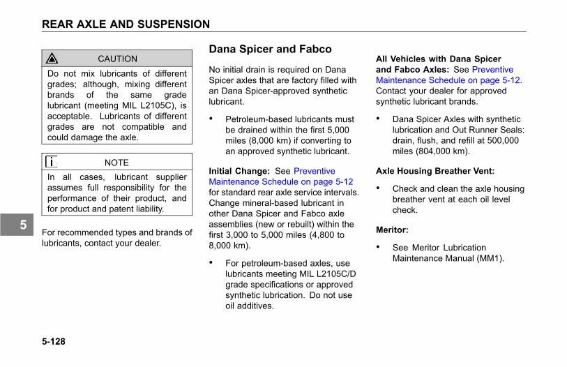
REAR AXLE AND SUSPENSION
CAUTION
Do not mix lubricants of differentgrades; although, mixing differentbrands of the same gradelubricant (meeting MIL L2105C), isacceptable. Lubricants of differentgrades are not compatible andcould damage the axle.
NOTEIn all cases, lubricant supplierassumes full responsibility for theperformance of their product, andfor product and patent liability.
For recommended types and brands oflubricants, contact your dealer.
Dana Spicer and Fabco
No initial drain is required on DanaSpicer axles that are factory filled withan Dana Spicer-approved syntheticlubricant.
• Petroleum-based lubricants mustbe drained within the first 5,000miles (8,000 km) if converting toan approved synthetic lubricant.
Initial Change: See PreventiveMaintenance Schedule on page 5-12for standard rear axle service intervals.Change mineral-based lubricant inother Dana Spicer and Fabco axleassemblies (new or rebuilt) within thefirst 3,000 to 5,000 miles (4,800 to8,000 km).
• For petroleum-based axles, uselubricants meeting MIL L2105C/Dgrade specifications or approvedsynthetic lubrication. Do not useoil additives.
All Vehicles with Dana Spicerand Fabco Axles: See PreventiveMaintenance Schedule on page 5-12.Contact your dealer for approvedsynthetic lubricant brands.
• Dana Spicer Axles with syntheticlubrication and Out Runner Seals:drain, flush, and refill at 500,000miles (804,000 km).
Axle Housing Breather Vent:
• Check and clean the axle housingbreather vent at each oil levelcheck.
Meritor:
• See Meritor LubricationMaintenance Manual (MM1).
5-128
5

REAR AXLE AND SUSPENSION
Rear Axle Alignment
Continual road shock and loadstresses may force the rear axlesout of alignment. If you detect rapidtire wear on the rear axles, you mayhave misaligned axles. If you suspectrapid tire wear, have your rear axlealignment checked and adjusted by anauthorized dealer.
In addition to pre-delivery inspections,suspension alignment should bechecked when any one of the followingconditions exist:
• Discovery of loose suspensionfasteners. (Loose, defined as anytorque below the recommendedtorque value.)
• Discovery of elongated holes in asuspension component.
• Bushing replacement.
• Excessive or abnormal tire wear.
5-129
5

STEERING SYSTEM
STEERING SYSTEM
Power Steering
Oil (under low pressure) provides thepower to operate the steering gear. Italso serves to lubricate moving partsand remove heat. A loss of steeringefficiency will occur if too much heatbuilds up in the system.
WARNING
Do not operate the vehicle if thesteering system is not workingproperly. You could lose controlof your vehicle if the steeringsystem is not in good workingcondition, which could result in aserious accident. For driving safety,visually check the steering gearand components. Frequent checksare important for driving safety,especially after traveling over roughroads. Failure to comply may resultin death, personal injury, equipmentor property damage.
If the steering feels unbalanced fromside-to-side while turning, check forthe following possible causes:
• unequal tire pressures
• vehicle overloaded or unevenlydistributed load
• wheels out of alignment
• wheel bearings improperlyadjusted
If you cannot correct the problem,check with an authorized dealer.
Your vehicle is equipped with integralpower steering. The system includesan engine-driven fluid pump, a fluidreservoir, the steering gear, andconnecting hoses. Because of thehydraulic power assist, little effort isrequired to turn the steering wheel.When no input is applied through thesteering wheel, the steering gear willreturn to the neutral position. If, forany reason, the power assist systemgoes out, steering the vehicle is stillpossible, yet it will require muchgreater effort.
Visually check the following parts:
• Crosstube: Is it straight?
5-130
5
STEERING SYSTEM
• Draglink tube clamp: Check forlooseness or interference.
• Ball joints and steering U-joints:Check for looseness.
• Steering wheel for excessivefree-play. Check the simplestprobable causes first:
a. unequal tire pressures
b. loose cap nuts
c. bent crosstube
d. lack of lubrication
• If these checks do not reveal theproblem, or if you correct themand still have a steering problem,take your truck to an authorizeddealer for evaluation.
Fluid Level and Refill
Have the power steering fluid andfilters changed at an authorized dealer.
CAUTION
When adding fluid, be sure to usefluid of the same type. While manyfluids have the same descriptionand intended purpose, they shouldnot be mixed due to incompatibleadditives. Mixing incompatible fluidsmay lead to equipment damage.
• Check and completely change thefluid level according to PreventiveMaintenance Schedule on page5-12. Use the following procedure:
NOTEBefore removing reservoir cover,wipe outside of cover so that no dirtcan fall into the reservoir.
• Maximum/Minimum level isindicated on the reservoir. Thesesame levels are also indicated bytwo lines on the dipstick in thereservoir.
• There are two ways to checkwhether the power steering fluidis at its proper level. Both checksare with the engine NOT running.
1. If you check the fluid with theengine and steering systemCOLD, the fluid level should beat/or above the Minimum indicatorlevel and should generally notexceed the middle point betweenMaximum and Minimum levelindicators.
2. If you check the fluid with theengine and steering systemWARM, the fluid should NOTexceed the Maximum levelindicator and should generallynot drop below the middle point
5-131
5

STEERING SYSTEM
between the Maximum andMinimum level indicators.
Fluid Filter Replacement
CAUTION
Servicing the power steering systemwithout bleeding it of trapped air maycause damage to the power steeringpump.
1. Replace both fluid and filter as perthe chart below.
2. Bleed the system if necessary.
Steering Shaft
The following are common torquespecifications for most steering shafts.
• Torque on U–joint pinch bolt andnut (7/16 in) 74–81 Nm (55 to 60lb-ft), lubricated.
• Torque on Pitman arm clamp boltand nut (3/4 in): 406–433 Nm (300to 320 lb-ft), lubricated.
• For off–highway vehicles, tightenthe U–bolts after the first day ortwo of operation. Then checkweekly.
5-132
5

STEERING SYSTEM
WARNING
If this chassis is equipped with anelectronic stability system (ESP)and any part of the steering system(e.g. linkage, steering driveline,column, front-end alignment, etc) isrepaired, removed, or disassembledin any way, or if the steering anglesensor is replaced, the steeringangle sensor must be recalibrated.Any repairs or adjustments to anypart of the steering system must beperformed by an authorized dealer.Failure to comply may result indeath, personal injury, equipment orproperty damage.
5-133
5

DRIVELINE
DRIVELINE
Driveshaft Maintenance
The slip joints and universal joints ofthe driveshaft should be lubricatedperiodically.
Use a good quality lithium-soap-baseor equivalent extreme pressure (E.P.)grease: NLGI Grade 2.
Dana SPL U-joints and driveshaftsshould be inspected every timea vehicle comes in for scheduledmaintenance (Refer to SpicerDriveshaft service manual DSSM-0100(3264-SPL) for detailed instructions).
Use only Spicer Driveshaft approvedlubricants when greasing Spicer SPLU-joints.
U-Joints
The slip joints and universal joints ofthe drive shaft should be lubricatedaccording to Preventive MaintenanceSchedule on page 5-12.
Use a good quality lithium-soap-baseor equivalent extreme pressure (E.P.)grease: NLGI Grade 2.
Use only Spicer Driveshaft approvedlubricants when greasing Spicer SPLU-joints.
For SPL170XL and SPL250XL, theU-joint lube interval changes after theinitial lube at 350,000 miles. Afterthe first lube interval, the U-jointneeds lubrication every 150,000 miles.Inspection of the U-joints is the sameregardless of when the U-joint greaseinterval happens.
WARNING
Improper lubrication of U-joints cancause them to fail prematurely. Thedriveshaft could separate from thevehicle and result in an accident.Make sure lubricant is purged at allfour ends of each U-joint and loosencaps if necessary. Also, regularlyinspect U-joints for excessive wearor movement, and repair or replaceas necessary. Failure to complymay result in death, personal injury,equipment or property damage.
5-134
5

TIRES AND WHEEL
TIRES AND WHEEL
Tires
WARNING
Do not repair damaged tires unlessyou are fully qualified and equippedto do so. Wheel and tire assembliescannot be worked on without propertools and equipment, such as:safety cages or restraining devices.Have all tire repairs performed byan expert. Stand away from thetire assembly while the expert isworking. Failure to do this mayresult in death or injury.
Your tires are a very important part ofyour vehicle’s whole braking system.How fast you can stop depends inlarge measure on how much frictionyou get between the road and yourtires. In addition, keeping your tires ingood condition is essential to the safe,efficient operation of your vehicle.
Regular, frequent inspection and theright care will give you the assuranceof safe and reliable tire operation.Here are some tips on maintainingyour tires.
Checking Inflation Pressure
Give your tires a visual test every day,and check inflation with a gauge everyweek:
• When checking tire pressure,inspect each tire for damage tosidewalls, cuts, cracks, unevenwear, rocks between duals, etc. Ifa tire appears underinflated, checkfor damage to the wheel assembly.Don’t forget to check between dualwheels. If you find wheel damage,have an expert tire service repairit.
• Maximum tire pressure will beindicated on the sidewall of a tire.
• Check pressure only when thetires are cool. Warm or hot tirescause pressure buildup and willgive you an inaccurate reading.So never deflate a warm tire to thespecified pressure.
5-135
5

TIRES AND WHEEL
Underinflated Tires
Low pressure is a tire’s worst enemy.Underinflation allows tires to fleximproperly, causing high temperaturesto build up. Heat causes early tiredamage such as flex break, radialcracks, and ply separation. Lowpressure may affect control of yourvehicle, especially at the front wheels.Most tire wear problems are causedby underinflation as the result of slowleaks, so you’ll want to check tirepressure regularly. Lower tire pressuredoes not provide better traction on iceor snow.
WARNING
Do not operate a vehicle withunderinflated tires. The extra heatcaused by underinflation can causesudden tire failure such as a tirefire or blow out which can causean accident resulting in death orpersonal injury. Low pressure mayaffect control at the front wheels,which could result in an accidentinvolving death or personal injury.Keep your tires inflated to themanufacturer's recommended airpressure.
WARNING
Do not attempt to raise the vehicleto remove or install a damaged tireand wheel assembly if you are notfully qualified and not equipped withthe proper tools and equipment.Do not attempt to re-inflate a tirethat has been run flat. Obtainexpert help. A person can beseriously injured or killed if usingthe wrong service methods. Trucktires and wheels should be servicedonly by trained personnel usingproper equipment. Follow OSHAregulations per section 1910.177.
NOTEFollow all warnings and cautionscontained within the tire and wheelmanufacturers literature.
5-136
5

TIRES AND WHEEL
1
TREAD CONTACTWITH ROAD
Proper-Inflation: thecorrect profile for fullcontact with the road.
2
TREAD CONTACTWITH ROAD
Under-Inflation:causes abnormal tiredeflection, which buildsup excessive heat,running the risk offailure. It also causesirregular wear.
3
TREAD CONTACTWITH ROAD
Over-Inflation:reduces the treadcontact area withthe road surface,concentrating all ofthe vehicle weighton the center of thetread. This causespremature wear of thetire.
Overloaded tires
Overloading your truck is as damagingto your tires as underinflation. Thefollowing chart shows how neglect ordeliberate abuse can affect the life ofyour tires.
EFFECT OF LOAD PRESSURE ON TIRE LIFEVehicle Load Normal 20% Over 40% Over 60% Over 80% Over 100% OverTire Pressure Normal 20% Low 30% Low 35% Low 45% Low 55% LowExpected Total TireMileage Normal 70% 50% 40% 30% 25%
Overinflated tires
Too much air pressure reduces the tiretread contact area and results in rapidwear in the center of the tread.
5-137
5

TIRES AND WHEEL
WARNING
Overinflated tires can causeaccidents. They wear more quicklythan properly inflated tires and aremore subject to punctures, cracks,and other damage. They could failand cause you to lose control ofyour vehicle resulting in an accidentcausing death or personal injury. Besure all tires are inflated correctlyaccording to the manufacturer'srecommendations.
Matching tires
Be sure to buy matched tires foryour vehicle, especially on the rearaxles. Mismatched tires can causestress between axles and cause thetemperature of your axle lubricant toget too hot. Matched tires will helpyour driveline last longer and will giveyou better tire mileage.
WARNING
Do not mismatch tires, it can bedangerous. Never mix tires ofdifferent design such as steel beltedradials and bias ply tires, etc. Mixingtire types and sizes will adverselyaffect the road-holding ability of bothtypes of tires and can lead to loss ofvehicle control and causing death orpersonal injury.
WARNING
Do not install regrooved orreinforcement-repaired tires onsteering axles. They could failunexpectedly and cause you to losecontrol of your vehicle resulting in anaccident causing death or personalinjury.
5-138
5

TIRES AND WHEEL
Replacing Tires
Front: Replace front tires when lessthan 4/32 in. of tread remains. Checkat three places equally spaced aroundthe tire.
Drive Axles or Trailers: Replace tireson drive axles or trailers when less than2/32 in. of tread depth remains in anymajor groove. Check at three placesequally spaced around the tire. Seethe next illustration for recommendedmeasuring points for tread depth.
Steer Tire Points (left), Drive TirePoints (right)
WARNING
Do not replace original equipmenttires with load ratings less than theoriginal tires. Doing so could leadto unintentional overloading of thetire, which could cause a failureresulting in loss of vehicle controland an accident. Failure to complymay result in death, personal injury,equipment or property damage.
NOTETo prolong your tires’ life and makethem safer, have their radial andlateral run-out checked at yourdealer. And of course you shouldhave your tires balanced anytimeyou change a tire.
Tire chains
If you need tire chains, install them onboth sides of each driving axle.
CAUTION
Chains on the tires of only onetandem axle can damage thedriveline U-joints and the interaxledifferential. Your repairs could becostly & time-consuming.
5-139
5

TIRES AND WHEEL
Speed Restricted Tires
WARNING
This vehicle may be equipped withspeed restricted tires. Check eachtire’s sidewall for maximum ratedspeed. The vehicle should not beoperated at sustained speed inexcess of maximum rated speed.Failure to comply with these speedrestrictions could cause sudden tirefailure which can result in death,personal injury or property damage.
Wheel Mounting andFastening
After the vehicle travels about 50 to 100miles (80 to 160 km), wheel mountingsseat in and will lose some initial torque.Check hub/wheel mountings after thisinitial period and retighten.
WARNING
Never use oil or grease on studs ornuts; improper torque readings willresult, which could cause improperwheel clamping and could leadto a wheel failure resulting in anaccident. Failure to comply mayresult in death, personal injury,equipment or property damage.
Wheel Cap Nut Torque
At the first scheduled lube interval,have all wheel cap nuts torqued totheir specified value listed in WheelCap Nut Torque on page 5-140. Afterthat, check wheel cap nuts at leastonce a week. Contact an authorizeddealer for information on the properinstallation procedure for the wheelson your truck. This is a job you maynot be able to do yourself. You needthe right torquing equipment to do it.
Wheel Cap Nut Torque
TORQUE FOR INNER & OUTER CAP NUTS & RIM CLAMP NUTSWHEEL & NUT CONFIGURATION STUD SIZENm Lb-Ft
3/4-16 610-680 450-500Steel or Aluminum Disc-TypeWheel; Double Cap Nut Mounting;Standard 7/8 Radius Ball Seat
1-1/8-16 610-680 450-500
5-140
5

TIRES AND WHEEL
TORQUE FOR INNER & OUTER CAP NUTS & RIM CLAMP NUTSWHEEL & NUT CONFIGURATION STUD SIZENm Lb-Ft
15/16-12 1,020-1,220 750-9001-1/8-16 1,020-1,220 750-900
Heavy-Duty Steel Disc-Type Wheel;Double Cap Nut Mounting;1-3/16 Radius Ball Seat: 1-15/16-12 1,020-1,220 750-900Hub-Piloted Disc-Type Wheelw/Two Piece Flanged Cap Nuts:Steel or Aluminum WheelPHP-10; Budd Uni-Mount-10;WDH-8
M22-1.5 610-680 450-500
3/4-16 240-270 175-200Stud Backnuts (when used)1-14 240-410 175-300
Rim Clamp Nut Torque1/2” Dia. 110-120 80-905/8” Dia. 220-250 160-185Cast Spoke Wheel Assembly
3/4” Dia. 305-335 225-245
Threads should be clean and dry. Donot lubricate wheel nuts or studs.
Proper Torque andSequence
Proper wheel torque can best beobtained on level ground. Install lugnuts and finger-tighten in the numericalsequence as shown below, see NutTightening Sequence for Hub PilotedDisc Wheels on page 5-142 or NutTightening Sequence for Stud PilotedDisc Wheels on page 5-142. This
procedure will ensure that the wheel isdrawn evenly against the hub. Torqueeach nut to the torque value listed inWheel Cap Nut Torque on page 5-140.
5-141
5

TIRES AND WHEEL
WARNING
Tighten wheel cap nuts properly.If they are not tightened properly,wheel nuts could eventually causethe wheel to become loose, tofail, and/or to come off while thevehicle is moving, possibly causingloss of control and may result indeath, personal injury, equipment orproperty damage.
Nut Tightening Sequence for HubPiloted Disc Wheels
Nut Tightening Sequence for StudPiloted Disc Wheels
Wheel Replacement WithDisc Brake Option
WARNING
Use only the wheel brand, sizeand part number originally installed.Use of a different wheel brand orsize could cause valve stem tointerfere with a brake componentwhich could lead to loss of vehiclecontrol. Failure to comply may resultin death, personal injury, equipmentor property damage.
Vehicles equipped with front discbrakes are fitted with wheels designedspecifically for disc brake applications.If it ever becomes necessary toreplace an original equipment wheel,the replacement wheel must be thesame brand and size as the take-offwheel. On vehicles equipped with 22.5in. disc wheels, installing the wrongreplacement wheel could result inthe wheel valve stem making contact
5-142
5

TIRES AND WHEEL
with the disc brake assembly. Wheninstalling any replacement wheel,always inspect the tires/wheels toensure there is adequate clearancebetween other vehicle components.
With the hood open, check forclearance between the wheel and discbrake assembly. Use a hydraulic jackto raise the front of the vehicle offthe ground to allow the wheel to spinfreely. While rotating the wheel, checkto ensure there is adequate clearancebetween the wheel and disc brakeassembly
WARNING
If the hood falls, anyone under itcould be injured. Always makesure that the hood hold open deviceengages when the hood is in itsopen position any time anyone getsunder the hood for any reason.
• The hood could hurt someonethat is in the way of its descent.Before lowering the hood, be sureno objects or people are in theway.
WARNING
Always support the vehicle withappropriate safety stands if it isnecessary to work underneath thevehicle. A jack is not adequate forthis purpose.
WARNING
Improperly mounting anddemounting tire and rim assembliesis dangerous. Failure to observeproper precautions could causethe tire-rim assembly to burstexplosively, causing death orpersonal injury. See the wheelmanufacturer's literature for theproper way to mount and demountyour tires and rims. Follow theirprecautions exactly.
5-143
5

TIRES AND WHEEL
Disc Wheels
WARNING
Use the correct components andtools when working on wheels.Grooves in the wheel disc or otherdamage to the disc can weaken thewheel and cause it to eventuallycome off. This could cause youto lose control of your vehicle,and may result in an accident.Failure to comply may result indeath, personal injury, equipment orproperty damage.
The end of the wheel wrench mustbe smooth. Burrs on the end of thewrench can tear grooves in the disc.These grooves may lead to cracks inthe disc, and can cause it to fail.
5-144
5
WHEEL BEARING
WHEEL BEARING
Wheel Bearing Adjustment
For safe, reliable operation andadequate service life, your wheelbearings must be adjusted properly atthe recommended intervals. Contactyour authorized dealer to make surethe wheel bearings are properlyadjusted.
5-145
5

TRANSMISSION MAINTENANCE
TRANSMISSIONMAINTENANCE
Introduction
Proper maintenance of thetransmission will ensure that thevehicle will operate efficiently.
To check the transmission fluid level,park the vehicle on a level ground. Foran automatic transmission the oil levelshould be checked with the engineidling and the transmission fluid atoperating temperature. Checking thefluid of a manual transmission may bedone with the engine off.
The recommended fluid replacementintervals contain an initial change anda separate interval for the changesafter the initial drain. When the oilneeds to be replaced, be sure to referto the manufacturer’s literature onthe correct grade and type of oil topurchase.
For more details, please refer tothe maintenance section in thetransmission manufacturer’s manualor service literature.
CAUTIONWhen adding oil, types andbrands of oil should not beintermixed because of possibleincompatibility, which coulddecrease the effectiveness of thelubrication or cause componentfailure.
Initial Change: drain and replaceaccording to Preventive MaintenanceSchedule on page 5-12; for sometransmissions this may not be required.
Oil Change
Change fluid according to changeprocedures specified in theTransmission Service Manual.Use the recommended types of oilas specified in the Operation andService Manual (included with vehicle).Select from the appropriate lubricantfor varying ambient (outside air)temperatures.
5-146
5

TRANSMISSION MAINTENANCE
Transmission LubricantsManual Transmission
Manual transmissions are designed sothat the internal parts operate in a bathof oil circulated by the motion of gearsand shafts.
Service Intervals
For recommended types and brandsof all lubricants, see the transmissionmanufacturer's Service Manual andPreventive Maintenance Schedule onpage 5-12.
Check all hoses for kinks, deterioration,chafing, and leaks. Adjust kinked orchafing hoses to eliminate restrictionsand prevent further wear. To ensureproper inspection, it may be necessaryto inspect under and inside frame railsand unclip harnesses, hoses and cablebundles.
Standard Transmission OilLevel
NOTEThe vehicle must be parked on levelground.
See the Transmission Operator'sManual for information on checking thetransmission oil level.
5-147
5

TRANSMISSION MAINTENANCE
Automatic TransmissionsService Intervals
Check daily with engine idling. SeePreventive Maintenance Schedule onpage 5-12 for service intervals.
Automatic Transmission OilLevel
NOTEThe vehicle must be parked on levelground.
See the Transmission Operator'sManual for information on checking thetransmission oil level.
5-148
5

CLUTCH
CLUTCH
Introduction
The clutch pedal transmits force fromthe operator to the clutch via hydraulicand air assist action. The clutch pedalposition is factory set and does notrequire adjustment.
Clutch Hydraulic Fluid
Visually inspect the clutch fluid from thereservoir. There are molded lines withthe letters MIN to indicate minimumfluid level and MAX to indicate themaximum fluid level recommended forproper operation. Be sure to maintainthe fluid between the MIN and MAXlevels indicated on the plastic reservoir.If the fluid level repeatedly goes belowthe MIN line, then it is time to haveyour clutch adjusted or the hydraulicsystem to be inspected for service.
To replace the fluid, locate the drainfitting on the air solenoid mounted tothe transmission housing. Open thisfitting and allow fluid to drain out of thesystem. Once all the fluid is drainedout, close the fitting and fill the systemthrough the master cylinder reservoirin the engine compartment. Once thesystem is full, then purge the system ofair by simultaneously pressing on thepedal and opening the fitting to allow
air to escape. Close the fitting whenfluid starts coming out. Then refill thereservoir. Repeat this until all air hasbeen purged from the system.
Replace with the recommended fluidComponent Lubrication Index on page5-38.
5-149
5

CLUTCH
Clutch Adjustment
Some clutches are self-adjustinghowever; there are manually adjustedclutches that will require the operatorto know when to adjust the clutch. Theclutch will need adjustment when yourclutch pedal stroke seems to get longerand its effectiveness at a seamlessshift becomes less.
Another sign of the clutch needingadjustment is the level of the fluid inthe reservoir. If the hydraulic fluid isnot leaking but the fluid level is gettinglower, then the clutch may need to beadjusted. Please take the vehicle toan authorized dealership to have theclutch adjusted.
Clutch Adjustment - NormalWear
See the clutch manufacturer's ServiceManual for the proper adjustmentprocedures.
5-150
5

INFORMATION
CONSUMER INFORMATION AND VEHICLE IDENTIFICATIONVehicle Identification . . . . . . . . . . . . . . 6-3General VIN Information . . . . . . . . . . . . . 6-4Component Identification. . . . . . . . . . . . . 6-7
CONSUMER INFORMATIONFederal Safety Standard Certification Label . . . . 6-8How to Order Parts . . . . . . . . . . . . . . . 6-8NHTSA Consumer Information . . . . . . . . . . 6-8Canadian Consumer Information . . . . . . . . . 6-9
6-1
6

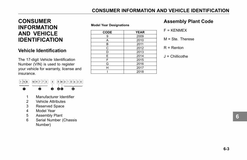
CONSUMER INFORMATION AND VEHICLE IDENTIFICATION
CONSUMERINFORMATIONAND VEHICLEIDENTIFICATION
Vehicle Identification
The 17-digit Vehicle IdentificationNumber (VIN) is used to registeryour vehicle for warranty, license andinsurance.
1 Manufacturer Identifier2 Vehicle Attributes3 Reserved Space4 Model Year5 Assembly Plant6 Serial Number (Chassis
Number)
Model Year Designations
CODE YEAR9 2009A 2010B 2011C 2012D 2013E 2014F 2015G 2016H 2017I 2018
Assembly Plant Code
F = KENMEX
M = Ste. Therese
R = Renton
J = Chillicothe
6-3
6
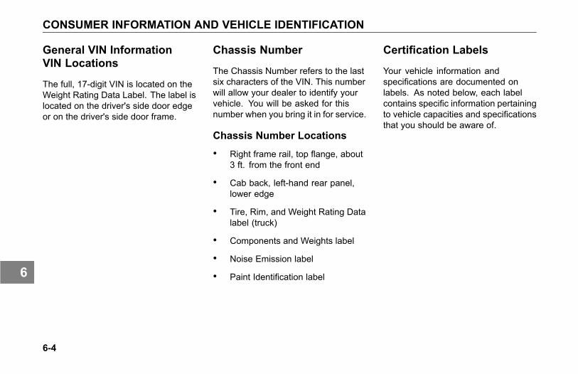
CONSUMER INFORMATION AND VEHICLE IDENTIFICATION
General VIN InformationVIN Locations
The full, 17-digit VIN is located on theWeight Rating Data Label. The label islocated on the driver's side door edgeor on the driver's side door frame.
Chassis Number
The Chassis Number refers to the lastsix characters of the VIN. This numberwill allow your dealer to identify yourvehicle. You will be asked for thisnumber when you bring it in for service.
Chassis Number Locations
• Right frame rail, top flange, about3 ft. from the front end
• Cab back, left-hand rear panel,lower edge
• Tire, Rim, and Weight Rating Datalabel (truck)
• Components and Weights label
• Noise Emission label
• Paint Identification label
Certification Labels
Your vehicle information andspecifications are documented onlabels. As noted below, each labelcontains specific information pertainingto vehicle capacities and specificationsthat you should be aware of.
6-4
6

CONSUMER INFORMATION AND VEHICLE IDENTIFICATION
Components and WeightsLabel
The Components and Chassis WeightLabel is located on either the driver’sside door edge or on the driver’sside door frame. It includes chassisnumber, chassis weight and grossweight, plus model information for thevehicle, engine, transmission, andaxles.
Tire and Rim Data Label
The Tire, Rim and Weight RatingData Label is located on the driver’sside door edge or on the driver’s sidedoor frame. It contains the followinginformation:
• GVWR - Gross Vehicle WeightRating
• GAWR FRONT, INTERMEDIATEand REAR - Gross Axle WeightRatings for Front, Intermediateand Rear Axle
• TIRE/RIM SIZES AND INFLATIONPRESSURES - Tire/Rim Sizesand Cold Pressure Minimums
• VIN including CHASSIS NUMBER
WARNING
Do not exceed the specified loadrating. Overloading can result inloss of vehicle control and personalinjury, either by causing componentfailures or by affecting vehiclehandling. Exceeding load ratingscan also shorten the service life ofthe vehicle.
The components of your vehicleare designed to provide satisfactoryservice if the vehicle is not loadedin excess of either the gross vehicleweight rating (GVWR), or the maximumfront and rear gross axle weight ratings(GAWRs).
NOTEGVW is the TOTAL SCALEWEIGHTthe vehicle is designed to carry.This includes the weight of theempty vehicle, loading platform,occupants, fuel, and any load.
6-5
6

CONSUMER INFORMATION AND VEHICLE IDENTIFICATION
Noise Emission Label
The Noise Emission Label is locatedin the driver's side door frame. Itcontains information regarding U.S.noise emission regulations, chassisnumber, and date of manufacture.
Paint Identification Label
The Paint Identification Label containsthe paint colors used by the factoryto paint your vehicle. It lists frame,wheels, cab interior and exteriorcolors. This label is located inside theglove box.
Federal Safety StandardCertification Label
The NHTSA regulations require a labelcertifying compliance with FederalSafety Standards, for United Statesand U.S. Territories, be affixed toeach motor vehicle and prescribewhere such label may be located.This certification label, which indicatesthe date of manufacture and otherpertinent information, is located onthe driver’s side door edge or on thedriver’s side door frame.
6-6
6

CONSUMER INFORMATION AND VEHICLE IDENTIFICATION
Component Identification
Each of the major components onyour vehicle has an identification labelor tag. For easy reference, recordcomponent numbers such as, model,serial, and assembly number.
Engine: For further information,please refer to the Engine Operationand Maintenance Manual.
Transmission: For both manualand automatic transmissions, theidentification number is stamped on atag affixed to the right rear side of thetransmission case.
Clutch: Enclosed in clutch housing.Location depends on manufacturer.
Steer Axle: The front axle serialnumber is stamped on a plate locatedon the center of the axle beam.
Drive Axles: The drive axle numberingsystem includes three labels or stamps:
1. Axle Specification Number, usuallystamped on the right rear side ofthe axle housing. This numberidentifies the complete axle.
2. Axle Housing Number Tag, usuallylocated on the left forward sideof the housing arm. This tagidentifies the axle housing.
3. Axle Differential CarrierIdentification, usually locatedon the top side of the differentialcarrier. The following informationis either stamped, or marked with ametal tag: Model No., ProductionAssembly No., Serial No., GearRatio, and Part Number.
6-7
6

CONSUMER INFORMATION
CONSUMERINFORMATION
Federal Safety StandardCertification Label
The National Highway Traffic SafetyAdministration regulations requirea label certifying compliance withFederal Safety Standards, for UnitedStates and U.S. Territories, be affixedto each motor vehicle and prescribewhere such label may be located.This certification label, which indicatesthe date of manufacture and otherpertinent information, is located on theleft hand cab door post.
How to Order Parts
Replacement parts may be obtainedfrom an authorized dealership.
When you order, it is IMPORTANTthat you have the following informationready:
• Your name and address.
• Serial number of the truck.
• The name of the part you need.
• The name and number of thecomponent for which the part isrequired.
• The quantity of parts you need.
• How you want your order shipped.
NHTSA ConsumerInformation
If you believe that your vehicle hasa defect which could cause a crashor could cause death or personalinjury, you should immediately informthe National Highway Traffic SafetyAdministration (NHTSA) in addition tonotifying the vehicle manufacturer.
If NHTSA receives similar complaints,it may open an investigation, andif it finds that a safety defect existsin a group of vehicles, it may ordera recall and remedy campaign.However, NHTSA cannot get involvedin individual problems between you,your dealer, and vehicle manufacturer.
Contacting NHTSA is possible throughtelephone, written mail and email.NHTSA also has a website where youcan input your comments directly tothem on the web. Please use any ofthe four ways to contact NHTSA:
6-8
6

CONSUMER INFORMATION
Toll Free 888-327-4236(800-4249153 TTY)8:00 am to 10:00 pm ETMonday-FridayOffice of DefectsInvestigations/CRDNVS-2161200 New Jersey Ave SE.Washington, D.C. 20590
www www.safercar.gov@ [email protected]
Canadian ConsumerInformation
Canadian customers whowish to reporta safety-related defect to TransportCanada, Defect Investigations andRecalls, may telephone the toll freehotline 1-800-333-0510, or contactTransport Canada by mail at:
Transport Canada, ASFADPlace de Ville Tower C330 Sparks StreetOttawa ON K1A 0N5
For additional road safety information,please visit the Road Safety websiteat:
http://www.tc.gc.ca/roadsafety/menu.htm
6-9
6


Index
Index5th wheel
maintenance 5-103
AAbout This Manual 1-3Accessories
cigarette lighter 3-90radio 3-90
Adding electrical options 5-82Additional sources of information 1-9
California proposition 65warning 1-6data recorder 1-7installed equipment - operator'smanuals 1-9other sources 1-9
Adjustable auxiliary axles 4-45liftable/non-steerable pushercalibration 4-48liftable/steerable calibration 4-48tag axle calibration 4-48
After-treatment system
introduction 4-54Air compressor 5-55Air dryer 5-51Air dryer (Bendix® AD-IS series) 5-52Air dryer overhaul 5-52Air gauges
air pressure - air suspension airbags #1 & #2 3-47pusher axle(s) air pressure 3-43tag axle air pressure 3-43tractor air brake pressure 3-47tractor air brake pressure -primary/secondary 3-12trailer air brake pressure 3-48trailer air tank pressure 3-48
Air systemair cleaners 5-98air compressor 5-55air dryer 5-51air filter restriction gauge 3-44air gauges and air leaks 5-54air intake system 5-97
draining air tanks 5-53primary air pressure gauge 5-54secondary air pressure gauge 5-54turbocharger 5-97
Air system maintenance 5-48Air tanks 5-53Alarms
headlight on alarm 3-41low coolant level alarm 3-40stop engine alarm 3-40
Alert screensfault alert 4-41impact alert 4-40level 1 following distance alert 4-40level 2 following distance alert 4-40level 3 following distance alert 4-40stationary object alert 4-40
Anti-lock brakestrailer ABS 4-24trailer ABS (without PLC) 4-25wheel spin control 4-31
Anti-lock brakes (ABS)
Index-1
7

Index
electronic stability program(ESP) 4-26roll stability program (RSP) 4-26
Appliances 3-91Automatic transmissions
oil level 5-148service intervals 5-148
Auxiliary axles 4-45
BBatteries
battery access 5-83battery care 5-87battery charging 5-87jump starting vehicles 2-8removing and installingbatteries 5-85
Brake gaugestractor air brake pressure 3-47tractor primary/secondary air brakepressure 3-12trailer air brake pressure 3-48trailer air tank pressure 3-48
Brake systemadjustment 5-57
retarders 4-33roll stability program (RSP) 4-26spring brakes 2-20yaw control 4-27
Bulb replacementheadlight 5-77
CCab and frame access 1-10Cab storage 3-91
glove box 3-91California Proposition 65 Warning 1-6Certification labels
components and weights label 6-5federal safety standard certificationlabel 6-6noise emission label 6-6part identification label 6-6tire and rim data label 6-5
Cigarette lighter 3-90Clock
to set alarm ON/OFF 3-27to set alarm time 3-28to set clock display 3-27to set home/local time 3-28
Clutchclutch brake 4-16clutch linkage adjustment 5-150clutch travel 4-16double clutching 4-18identification 6-7riding the clutch 4-20
Clutch maintenance 5-149Component identificationreference 6-7
Consumer informationFederal safety standards 6-8how to order parts 6-8
Controls 3-90Cooling system
adding coolant 5-73fan 5-96fan clutch 5-96maintenance 5-71
Cooling system maintenance 5-71
DDaily checks 1-34Data recorder 1-7Daytime running light (DRL) 3-63
Index-2
7
Index
Deck plate access 1-13DEF filter 5-119Diesel Exhaust Fluid Tank 5-119Displays/menu screens
clock display 3-27driver performance center 3-20fuel economy 3-24ignition timer 3-23settings 3-27to set time 3-28trip information 3-24truck information 3-25virtual gauges 3-23warning and faults 3-26
Door lock 1-11key fob synchronization 1-13remote keyless entry (RKE)system 1-12
Drive axlesidentification 6-7
Driver performance center 3-14fuel economy 3-24ignition timer 3-23menu screens 3-20settings 3-27trip information 3-24
truck information 3-25virtual gauges 3-23warning and faults 3-26
Driver'scheck list 1-33daily checks 1-34weekly checks 1-37
Driving tipscoasting 4-55descending a grade 4-56engine RPM 4-56fuel economy 4-59optimal engine speed 4-57using the driver informationdisplay 4-58using the driver performancecenter 3-14using the tachometer 4-57
Dual range (two-speed) rear axle 4-43
EElectrical and alternatorprecautions 5-90
Electrical systemadding electrical options 5-82
batteries 5-83battery care 5-87battery charging 5-87electrical and alternatorprecautions 5-90fuses, circuit breakers andrelays 5-78jump starting vehicles 2-8removing and installingbatteries 5-85
Electrical system maintenance 5-76Emergency
battery connections 2-10emergency equipment kit 1-33jump starting vehicles 2-8
Engineair cleaners 5-98air intake system 5-97drive belts 5-95exhaust system 5-99identification 6-7lubrication 5-92pipe and hose clamp torquevalues 5-36, 5-93
Engine (block) heater 5-75Engine lubrication 5-92
Index-3
7

Index
Engine maintenance 5-91Engine operation
engine block heater 4-6engine control display 4-14engine cool down 4-63engine fan control 4-12winterfronts 4-13
FFifth wheel
maintenance 5-103Filter Minder 5-99Frame fastener torquerequirements 5-104
Front axle and suspensionmaintenance 5-106
Fuel gaugesfuel filter restriction pressure 3-44fuel tank(s) level 3-9
Fuel shut-off valve 4-64Fuel specification 4-63Fuel system
fuel filters 5-100shut-off valves 5-100
Fuses, circuit breakers andrelays 5-78
GGauges
air pressure - primary 3-12air pressure - secondary 3-12auxiliary transmission oiltemperature 3-49diesel exhaust fluid (DEF) 3-14engine coolant (water)temperature 3-11engine oil pressure 3-11, 3-45engine oil temperature 3-45fuel filter restriction pressure 3-44fuel tank(s) level 3-9primary air pressure 5-54pusher axle(s) air pressure 3-43secondary air pressure 5-54speedometer 3-9suspension load air pressure#1 3-47suspension load air pressure#2 3-47tachometer 3-10
tag axle air pressure 3-43tractor brake application airpressure 3-47trailer air tank air pressure 3-48trailer brake application airpressure 3-48transfer case oil temperature 3-48transmission retarder oiltemperature 3-49
Gauges (optional)air filter restriction 3-44drive axle temperature (forward andrear) 3-46fuel pressure 3-46manifold pressure 3-45transmission temperature 3-46
Gauges (standard)tachometer 4-57
GAWR - Gross Axle WeightRating 1-32
GCW - Gross CombinationWeight 1-32
Glove box 3-91Guide to the Warning Symbols 3-29GVWR - Gross Vehicle WeightRating 1-32
Index-4
7

Index
HHeadlight aiming 5-78Headlight replacement 5-77Headlight switch 3-64Heater and air conditioner 5-110
air conditioner 5-114heater 5-113
Heater and air conditionermaintenance 5-110
Heating and air conditioningair flow control dial 3-85cooling 3-86defrost vents 3-85dehumidify 3-87fan control dial 3-85floor and defrost vents 3-85floor vents 3-85fresh air/recirculation switch 3-85heating 3-87instrument panel and de-mistervents 3-85instrument panel, de-mister andfloor vents 3-85sleeper heater - A/C controls 3-88sleeper override 3-86temperature control dial 3-85
what each control does 3-85windshield defog and defrost 3-88
Hood tiltinghood hold downs 1-15hood hold-open device 1-17hood latch 1-16
IIgnition key switch 3-63Installed Equipment - Operator'sManuals 1-9
Instrument cluster 3-7Instrument panel 3-5Instrumentation
driver performance center 3-12instrument cluster 3-7instrument panel 3-5instrument system self test 3-8menu control switch (MCS) 3-20
JJump starting vehicles 2-8
KKeys
remote keyless entry (RKE) 1-11Kingpin lubrication 5-106
LLap/Shoulder belt 1-21Load distribution 1-32Low voltage disconnect (LVD) 3-60Lubricant specifications 5-34
MMaintenance
5th wheel 5-103air cleaners 5-98air conditioner 5-114air intake system 5-97air system 5-48Allison transmissionlubrication 5-42brake adjustment 5-57brake inspection 5-58chrome and aluminumsurfaces 5-62cleaning vinyl and upholstery 5-66
Index-5
7

Index
clutch 5-149cooling system 5-71driver's check list 1-33Eaton/Dana axle lubrication 5-45electrical system 5-76emergency welding 5-102engine 5-91exterior 5-62frame fastener torquerequirements 5-104frame fastener torque table 5-104front axle and suspensionlubrication 5-106fuel system 5-100Fuller transmission lubrication 5-40heater 5-113inspection 5-107lubricant specifications 5-34maintenance schedule 5-12Meritor axle lubrication 5-44noise and emission controlstandards 5-115oil changes 5-43painted surfaces 5-62preventive maintenance 5-9rear axle alignment 5-129
rear axle and suspension 5-124rear axle lubrication 5-127rear suspension fasteners torquetable 5-126rear suspension U-bolt torquetable 5-127safety restraint system -inspection 5-66safety restraint system - inspectionguidelines 5-68sliding fifth wheel 5-105Spicer transmissionlubrication 5-42stainless steel 5-63steering and driveline 5-130steering gear lubrication 5-47tail pipe surface cleaning 5-63tires 5-135transmission 5-146U-bolt torque 5-108U-bolt torque table 5-109universal joint lubrication 5-46vehicle cleaning 5-64washing chassis 5-66washing exterior 5-65wheel alignment 5-107
wheel bearing lubrication 5-46windshield wiper/washer 5-70
Maintenance Proceduresinspection of the engine oillevel 5-92topping up the engine oil 5-93
Maintenance schedule 5-9Malfunction Indicator Lamp (MIL) 3-40Manual transmission 4-15
clutch brake 4-17clutch travel 4-17double clutching 4-18release bearing wear 4-20riding the clutch 4-20shifting gears 4-17
Mirrors 3-75mirror heat button 3-76power mirror switch 3-76
NNoise and emission controlmaintenance 5-115
Noise control inspections 5-117air intake system 5-117diesel particulate filters 5-119
Index-6
7

Index
engine fan and shroud 5-121engine mounted noiseinsulators 5-117exhaust system 5-118exhaust tail pipe 5-121hood insulation blanket 5-121inner fender shields and cabskirt 5-122joints and clamps 5-118maintenance log 5-122piping 5-119
OOil changes 5-43Oil gauges
auxiliary transmission oiltemperature 3-49engine oil pressure 3-11, 3-45engine oil temperature 3-45transfer case oil temperature 3-48transmission retarder oiltemperature 3-49
Operating procedureautomatic and automatedtransmissions 4-19
refueling 4-64stopping procedures 4-65transmission retarder 4-34
PPainting 5-103Pipe and hose clamp torquevalues 5-93
Pressure gaugesengine oil pressure 3-11, 3-45
Pusher axle(s) air pressuregauge 3-43
RRear axle - dual range(two-speed) 4-43
Rear axle and suspensionmaintenance 5-124rear suspension fasteners 5-126visual inspection 5-125
Refueling 4-63fuel specification 4-64
Remote Keyless Entry (RKE) 5-90batteries 1-13key fob operation 1-12
key fob synchronization 1-13Remote keyless entry (RKE) 1-12
SSafe vehicle operation 1-30Safety
about this manual 1-3air suspension height/airpressure 4-52cab and frame access 1-10deck plate access 1-13deflated air springs 4-53driver's check list 1-33emergency equipment kit 1-33introduction 1-3safe vehicle operation 1-30safety alerts 1-3suspension air pressuregauge 4-52vehicle loading 1-31vehicle safety 1-5
Safety alerts 1-3Safety restraint belts 1-20
belt damage and repair 1-25during pregnancy 1-24
Index-7
7

Index
inspection 5-66safety restraint tips 1-28
Seat adjustment 1-19driver's seat with airsuspension 1-19reclining seats 1-19standard driver's seat 1-19
Seat belts 1-19adjustments 1-19belt damage and repair 1-25during pregnancy 1-24Komfort-Lok feature 1-23lap/shoulder belt 1-21safety restraint tips 1-28
Seatsadjustments 1-19Komfort-Lok feature 1-23tether belts 1-22To adjust an external tetherbelt 1-23
Seats and restraints 1-19Shut-down
fuel specification 4-64location of fuel shut-off valves 4-64refueling 4-63sleeper bunk 4-61
Sleeper bunk 4-61sleeper restraint 4-62
Sliding 5th wheelmaintenance 5-105
Sliding Fifth wheelmaintenance 5-105
Starting procedurecold temperature 4-6engine warm-up 4-7ether metering 4-10normal temperature 4-5
Steer axleidentification 6-7
Steering and drivelinemaintenance 5-130fluid level and refill 5-131
Steering column 3-67tilt/telescoping 3-67trailer brake hand valve 3-72turn signal/high beam switch 3-69
Steering system maintenancesteering shaft 5-132
Steering wheel controls 3-72Suspension lubrication 5-106Switches
2 speed transfer case 3-59
ABS off-road switch 3-51accessory air switch 3-54air conditioner switch 3-85auxiliary light switch 3-54axle switch, diff-lock - dual 3-50axle switch, diff-lock - forwardrear 3-50axle switch, diff-lock - rear rear 3-50axle switch, diff-lock - singlerear 3-51axle switch, diff-lock - steer 3-50axle switch, inter axle differentiallocked (tandem) 3-51axle switch, pusher 3-57axle switch, tag 3-57axle switch, two speed 3-51back up alarm mute switch 3-51beacon light switch 3-54brake level switch 3-52brake on/off switch 3-52cab dimmer 3-52cruise control 4-37cruise control on/off switch 3-52cruise control set/resumeswitch 3-52dash switches 3-50
Index-8
7

Index
daytime running light switch 3-54diesel particulate filter (DPF)regeneration switch 3-53dome light switch 3-54dual range rear axle switch 4-43dump truck gate switch 3-52engine fan override switch 3-53engine fan switch 4-12engine heater switch 3-53ether start switch 3-52exterior lights self test switch 3-55fifth wheel slide switch 3-53flood light switch 3-55fog light switch 3-55forward power take-off (PTO)switch 3-56forward trailer axle lift switch 3-58fresh air/recirculation switch 3-85fuel heater switch 3-54hazard light switch 3-55headlight switch 3-64headlight switch and parkinglights 3-55ignition key switch 3-63low voltage disconnect (LVD) 3-51marker light switch 3-55
marker/clearance/cab lightswitch 3-56marker/clearance/trailer lightswitch 3-56mud & snow traction control 3-56off-road ABS function switch(option) 4-32optional deep snow and mudswitch 4-31parking brake valve 3-51pintle hook switch 3-57power door lock 3-77power take-off (PTO) switch 3-56power window 3-77rear power take-off (PTO)switch 3-56rear trailer axle lift switch 3-58remote throttle switch 3-53roofdenser switch 3-57shutdown switch 3-53sleeper override 3-86spare switch 3-54spot light switch 3-56suspension dump switch 3-57suspension lift switch 3-57third axle lift switch 3-57
trailer axle (3rd axle) lift switch 3-58trailer belly dump switch 3-58trailer dump gate switch 3-58trailer hotline switch 3-58trailer marker light interrupterswitch 3-69trailer suspension air dump 3-58transfer case 3-59turn signal/high beam switch 3-69under hood air intake 3-53winch clutch switch 3-59windshield wipers/washer 3-71
TTag axle air pressure gauge 3-43Telematic system
care and operation 3-94disclaimer 3-95
Temperature gaugesengine oil temperature 3-45transmission retarder oiltemperature 3-49water temperature (enginecoolant) 3-11
Tether belts 1-22
Index-9
7

Index
Tires 5-135inflation check 5-135replacement 5-139tire chains 5-139
Tires and wheelswheel cap nut torquesequence 5-141wheel cap nut torque table 5-140wheel mounting andfastening 5-140
Transmissionidentification 6-7lubricants 5-147maintenance 5-146oil change 5-146shifting gears in a new vehicle 4-17transmission tips 4-20
Transmission maintenance 5-146Transmission temperature gauges
auxiliary transmission oiltemperature 3-49
Transmissionsautomatic and automated 4-19auxiliary transmission 4-20transmission retarder 4-34
Turbocharger 5-97
VVehicle identification
assembly plant code 6-3chassis number 6-4chassis number locations 6-4model year designations table 6-3VIN number 6-3VIN number locations 6-4
Vehicle loading 1-31GAWR 1-32GCW 1-32GVWR 1-32load distribution 1-32
Vehicle recoverydriver controlled maindifferential 2-16recovery guidelines 2-12recovery hitch capacities 2-18recovery hitch connection 2-14recovery hitch installation 2-15recovery procedure 2-13recovery rigging 2-19returning vehicle to service 2-20sand, mud, snow and ice 2-22spring brakes 2-20towing the vehicle 2-23
Vehicle safety 1-5
WWarning light/indicator symbols
anti-lock brake system (ABS) 3-37anti-lock brake system (ABS),trailer 3-38axle, inter-axle differential locked(tandem axles) 3-38axle, traction control 3-37dump truck, body up 3-39dump truck, gate 3-39dump truck, trailer body up 3-39emissions, diesel particulate filter(DPF) 3-39emissions, high exhaust systemtemperature (HEST) 3-39engine brakesaver or transmissionretarder 3-42engine, check engine 3-40engine, engine fan 3-40engine, ether start 3-40engine, heater 3-40engine, low coolant level 3-40engine, retarder (brake) 3-40
Index-10
7
Index
engine, stop engine 3-40engine, wait to start 3-41lane departure warning (LDW) 3-41lights, high beam 3-41malfunction indicator lamp 3-40park brake 3-38power take-off (PTO) 3-41power take-off (PTO), pumpmode 3-41rationality check 3-38refrigerator 3-41seat belt, fasten 3-42service transmission 3-42suspension dump 3-42tire inflation 3-42transmission, auxiliary 3-42transmission, check 3-42turn signal, left 3-42turn signal, right 3-42water in fuel (WIF) 3-41wheel spin control 4-30
Weekly checks 1-37Welding (emergency) 5-102What to do if... 2-3
engine is overheating 2-5
engine oil pressure lamp turnson 2-4fuse or relay blows 2-6low air alarm turns on 2-3stop engine lamp turns on 2-4you need roadside assistance 2-3
Windshield wiper/washer 5-70Windshield wipers/washer 3-71
Index-11
7


![The Rosetta stone · 2011. 1. 7. · the rosettastone printedbtorderofthetrusteesofthebritishmuseum. london: soldatthebritishmuseum. pricesixpence, [allrightsreserved.]](https://img.pdfslide.us/doc/110x75/60abf202266ea82dbd7d9310/the-rosetta-stone-2011-1-7-the-rosettastone-printedbtorderofthetrusteesofthebritishmuseum.jpg)