Embed Size (px)
Citation preview
Owner's Manual forVehicle
The Ultimate DrivingMachine
ContentsA-Z
Online Edition for Part no. 01 40 2 606 521 - 03 11 490


650i Owner's Manual for VehicleThank you for choosing a BMW.The more familiar you are with your vehicle, the better control youwill have on the road. We therefore strongly suggest:Read this Owner's Manual before starting off in your new BMW.Also use the Integrated Owner's Manual in your vehicle. It con‐tains important information on vehicle operation that will help youmake full use of the technical features available in your BMW. Themanual also contains information designed to enhance operatingreliability and road safety, and to contribute to maintaining thevalue of your BMW.Any updates made after the editorial deadline for the printed orintegrated Owner's Manual are located in the appendix of theprinted quick reference for the vehicle.Supplementary information can be found in the additional bro‐chures in the onboard literature.We wish you a safe and enjoyable drive.BMW AG
Online Edition for Part no. 01 40 2 606 521 - 03 11 490

© 2011 Bayerische Motoren WerkeAktiengesellschaftMunich, GermanyReprinting, including excerpts, only with the writtenconsent of BMW AG, Munich.US English II/11, 03 11 490Printed on environmentally friendly paper, bleachedwithout chlorine, suitable for recycling.
Online Edition for Part no. 01 40 2 606 521 - 03 11 490

ContentsThe fastest way to find information on a partic‐ular topic or item is by using the index, refer topage 272.
Using this Owner's Manual6 Notes
At a glance12 Cockpit19 iDrive25 Voice activation system27 Integrated Owner's Manual in the vehicle
Controls32 Opening and closing53 Adjusting62 Transporting children safely65 Driving74 Displays84 Lamps88 Safety101 Driving stability control systems106 Driving comfort123 Climate control128 Interior equipment132 Storage compartments
Driving tips138 Things to remember when driving
Navigation146 Navigation
Entertainment164 Tone166 Radio173 CD/multimedia
Communication196 Telephone207 Office216 Contacts218 BMW ConnectedDrive
Mobility226 Refueling228 Fuel229 Wheels and tires236 Engine compartment238 Engine oil241 Maintenance243 Replacing components248 Breakdown assistance254 Care
Reference260 Technical data263 Short commands of the voice activation
system272 Everything from A to Z
Seite 5
Online Edition for Part no. 01 40 2 606 521 - 03 11 490
Re
fere
nce
Mob
ility
Com
mun
icat
ion
Ente
rtain
men
tNa
vigat
ion
Drivi
ng ti
psCo
ntro
lsAt
a gl
ance

NotesUsing this Owner's ManualThe fastest way to find information on a partic‐ular topic is by using the index.An initial overview of the vehicle is provided inthe first chapter.
Updates made after the editorialdeadlineAny updates made after the editorial deadline forthe Owner's Manuals are located in the appen‐dix of the printed quick reference for the vehicle.
Additional sources of informationShould you have any questions, your servicecenter will be glad to advise you at any time.Information on BMW, e.g., on technology, isavailable on the Internet: bmwusa.com.
Symbols Indicates precautions that must be followed
precisely in order to avoid the possibility of per‐sonal injury and serious damage to the vehicle.◄ Marks the end of a specific item of informa‐tion.* Indicates special equipment, country-specificequipment and optional accessories, as well asequipment and functions not yet available at thetime of printing."..." Identifies Control Display texts used to se‐lect individual functions.›...‹ Verbal instructions to use with the voice ac‐tivation system.››...‹‹ Identifies the answers generated by thevoice activation system.
Refers to measures that can be taken to helpprotect the environment.
Symbols on vehicle components Indicates that you should consult the rele‐
vant section of this Owner's Manual for infor‐mation on a particular part or assembly.
Your individual vehicleYou have decided in favor of a vehicle with indi‐vidualized equipment and features.This Owner's Manual describes the entire arrayof options and equipment available for a specificmodel.As a result, the manual may contain accessoriesand equipment that you may not have specifiedfor your own vehicle.All options and special equipment are markedwith an asterisk *.For options and equipment not described in thisOwner's Manual, please refer to the Supple‐mentary Owner's Manuals.On right-hand drive vehicles, some controls arearranged differently than shown in the illustra‐tions.
Status of the Owner's ManualThe manufacturer of your vehicle pursues a pol‐icy of constant development that is conceivedto ensure that our vehicles continue to embodythe highest quality and safety standards. In rarecases, therefore, the features described in thisOwner's Manual may differ from those in yourvehicle.
Updates made after the editorialdeadlineAny updates made after the editorial deadline forthe Owner's Manuals are located in the appen‐dix of the printed quick reference for the vehicle.
Seite 6
6Online Edition for Part no. 01 40 2 606 521 - 03 11 490
Note
s

For your own safetyMaintenance and repairsAdvanced technology, e.g., the use of modernmaterials and high-performance electronics, re‐quires suitable maintenance and repair meth‐ods.Therefore, have this work performed only by aBMW center or a workshop that works accord‐ing to BMW repair procedures with appropri‐ately trained personnel.
If this work is not carried out properly, there isthe danger of subsequent damage and relatedsafety hazards.
Parts and AccessoriesFor your own safety, use genuine parts and ac‐cessories approved by BMW. When you pur‐chase accessories tested and approved byBMW and Genuine BMW Parts, you simultane‐ously acquire the assurance that they have beenthoroughly tested by BMW to ensure optimumperformance when installed on your vehicle.BMW warrants these parts to be free from de‐fects in material and workmanship. BMW will notaccept any liability for damage resulting from in‐stallation of parts and accessories not approvedby BMW. BMW cannot test every product madeby other manufacturers to verify if it can be usedon a BMW safely and without risk to either thevehicle, its operation, or its occupants. GenuineBMW Parts, BMW Accessories and other prod‐ucts approved by BMW, together with profes‐sional advice on using these items, are availablefrom all BMW centers. Installation and operationof non-BMW approved accessories such asalarms, radios, amplifiers, radar detectors,wheels, suspension components, brake dustshields, telephones, including operation of anymobile phone from within the vehicle withoutusing an externally mounted antenna, or trans‐ceiver equipment, for instance, CBs, walkie-talkies, ham radios or similar accessories, maycause extensive damage to the vehicle, com‐promise its safety, interfere with the vehicle'selectrical system or affect the validity of theBMW Limited Warranty. See your BMW center
for additional information. Maintenance, re‐placement, or repair of the emission control de‐vices and systems may be performed by any au‐tomotive repair establishment or individualusing any certified automotive part.
California Proposition 65 WarningCalifornia laws require us to state the followingwarning:Engine exhaust and a wide variety of automobilecomponents and parts, including componentsfound in the interior furnishings in a vehicle, con‐tain or emit chemicals known to the State of Cal‐ifornia to cause cancer and birth defects and re‐productive harm. In addition, certain fluidscontained in vehicles and certain products ofcomponent wear contain or emit chemicalsknown to the State of California to cause cancerand birth defects or other reproductive harm.Battery posts, terminals and related accessoriescontain lead and lead compounds. Wash yourhands after handling. Used engine oil containschemicals that have caused cancer in laboratoryanimals. Always protect your skin by washingthoroughly with soap and water.
Service and warrantyWe recommend that you read this publicationthoroughly. Your vehicle is covered by the fol‐lowing warranties:▷ New Vehicle Limited Warranty.▷ Rust Perforation Limited Warranty.▷ Federal Emissions System Defect Warranty.▷ Federal Emissions Performance Warranty.▷ California Emission Control System Limited
Warranty.Detailed information about these warranties islisted in the Service and Warranty InformationBooklet for US models or in the Warranty andService Guide Booklet for Canadian models.Your vehicle has been specifically adapted anddesigned to meet the particular operating con‐ditions and homologation requirements in yourcountry and continental region in order to deliverthe full driving pleasure while the vehicle is op‐erated under those conditions. If you wish to op‐
Seite 7
7Online Edition for Part no. 01 40 2 606 521 - 03 11 490
Re
fere
nce
Mob
ility
Com
mun
icat
ion
Ente
rtain
men
tNa
vigat
ion
Drivi
ng ti
psCo
ntro
lsAt
a gl
ance

erate your vehicle in another country or region,you may be required to adapt your vehicle tomeet different prevailing operating conditionsand homologation requirements. You shouldalso be aware of any applicable warranty limita‐tions or exclusions for such country or region. Insuch case, please contact Customer Relationsfor further information.
Reporting safety defectsFor US customersThe following only applies to vehicles ownedand operated in the US.If you believe that your vehicle has a defectwhich could cause a crash or could cause injuryor death, you should immediately inform the Na‐tional Highway Traffic Safety AdministrationNHTSA, in addition to notifying BMW of NorthAmerica, LLC, P.O. Box 1227, Westwood, NewJersey 07675-1227, Telephone1-800-831-1117.If NHTSA receives similar complaints, it mayopen an investigation, and if it finds that a safetydefect exists in a group of vehicles, it may ordera recall and remedy campaign.However, NHTSA cannot become involved inindividual problems between you, your dealer,or BMW of North America, LLC.To contact NHTSA, you may call the VehicleSafety Hotline toll-free at 1-888-327-4236(TTY: 1-800-424-9153); go to http://www.safe‐rcar.gov; or write to: Administrator, NHTSA, 400Seventh Street, SW., Washington, DC 20590.You can also obtain other information about mo‐tor vehicle safety from http://www.safercar.gov
For Canadian customersCanadian customers who wish to report asafety-related defect to Transport Canada, De‐fect Investigations and Recalls, may telephonethe toll-free hotline 1-800-333-0510. You canalso obtain other information about motor vehi‐cle safety from http://www.tc.gc.ca/roadsafety.
Seite 8
8Online Edition for Part no. 01 40 2 606 521 - 03 11 490
Note
s

Seite 9
9Online Edition for Part no. 01 40 2 606 521 - 03 11 490
Re
fere
nce
Mob
ility
Com
mun
icat
ion
Ente
rtain
men
tNa
vigat
ion
Drivi
ng ti
psCo
ntro
lsAt
a gl
ance

Online Edition for Part no. 01 40 2 606 521 - 03 11 490

At a glanceThese overviews of buttons, switches and
displays are intended to familiarize you with yourvehicle. You will also become quickly acquaintedwith the available control concepts and options.
Online Edition for Part no. 01 40 2 606 521 - 03 11 490

CockpitAll around the steering wheel
1 Opening and closing the rear win‐dow 44
2 Open and close windows together 443 Open and close rear windows 434 Open and close front windows 435 Exterior mirror operation 596 Driver assistance systems*
Active Blind Spot Detec‐tion* 98
Lane departure warning* 97
Night Vision with pedestrian de‐tection* 118
Head-up Display* 121
7 Lamps
Front fog lamps* 87
Parking lamps 84
Low beams 84
Automatic headlamp con‐trol* 85Daytime running lights* 85Adaptive light control* 85High-beam Assistant* 86Instrument lighting 87
8 Steering column stalk, leftTurn signal 69
High beams, head‐lamp flasher 69
Seite 12
12Online Edition for Part no. 01 40 2 606 521 - 03 11 490
Cock
pit

High-beam Assistant* 86
Roadside parking lamps 85
Computer 76
9 Steering wheel buttons, leftStore speed* 106
Resume speed 107
Cruise control on/off, inter‐rupt 106
10 Instrument cluster 1411 Steering wheel buttons, right
Entertainment source
Volume
Voice activation* 25
Telephone* 196
12 Steering column stalk, rightWindshield wipers 69
Rain sensor* 70
Clean the windshields and head‐lamps* 70
13 Start/stop the engine and switchthe ignition on/off 66
14 Horn15 Steering wheel heating* 61
16 Adjust the steering wheel 61
17 Unlocking the hood18 Open the trunk lid 40
Seite 13
13Online Edition for Part no. 01 40 2 606 521 - 03 11 490
Re
fere
nce
Mob
ility
Com
mun
icat
ion
Ente
rtain
men
tNa
vigat
ion
Drivi
ng ti
psCo
ntro
lsAt
a gl
ance

Instrument cluster
1 Fuel gauge 742 Speedometer3 Indicator/warning lamps 144 Tachometer 755 Engine oil temperature 75
6 External temperature 757 Electronic displays 168 Miles, trip miles 769 Clock 7910 Reset miles 76
Indicator/warning lampsInstrument cluster
The indicator and warning lamps can light up ina variety of combinations and colors.Several of the lamps are checked for properfunctioning when the engine is started or the ig‐nition is switched on, and light up briefly in theprocess.
Overview: indicator/warning lamps
Symbol Function or system
Turn signal
Parking brake
Parking brake in Canadian models
Automatic Hold*
Front fog lamps*
Seite 14
14Online Edition for Part no. 01 40 2 606 521 - 03 11 490
Cock
pit

Symbol Function or system
High beams
High-beam Assistant*
Parking lamps, headlamp control
Cruise control*
Lane departure warning*
DSC Dynamic Stability Control
DSC Dynamic Stability Control orDTC Dynamic Traction Control
Tire Pressure Monitor*Flat Tire Monitor
Safety belts
Airbag system
Steering system
Symbol Function or system
Emissions
Brake system
Brake system in Canadian models
Antilock Brake System ABS
Antilock Brake System ABS in Cana‐dian models
Text messagesText messages in combination with a symbol inthe instrument cluster explain a Check Controlmessage and the meaning of the indicator andwarning lamps.
Supplementary text messagesAdditional information on the Control Display,e.g., on the cause of a malfunction or the re‐quired action, can be called up via Check Con‐trol, refer to page 82.The text of urgent messages is displayed auto‐matically.
Seite 15
15Online Edition for Part no. 01 40 2 606 521 - 03 11 490
Re
fere
nce
Mob
ility
Com
mun
icat
ion
Ente
rtain
men
tNa
vigat
ion
Drivi
ng ti
psCo
ntro
lsAt
a gl
ance
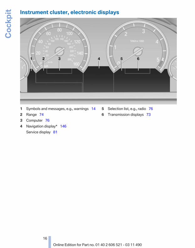
Instrument cluster, electronic displays
1 Symbols and messages, e.g., warnings 142 Range 743 Computer 764 Navigation display* 146
Service display 81
5 Selection list, e.g., radio 766 Transmission displays 73
Seite 16
16Online Edition for Part no. 01 40 2 606 521 - 03 11 490
Cock
pit

All around the center console
1 All around the interior rearview mir‐ror 18
2 Control Display 193 Glove compartment 1324 Air vent 1265 Hazard warning system 248
Central locking system 39
6 Radio 166CD/multimedia 173
7 Automatic climate control 1238 Controller with buttons 199 Parking brake 67
Automatic Hold* 67
10 Opening and closing the converti‐ble top 46
11 PDC Park Distance Con‐trol* 107Top View* 112Backup camera* 110Parking assistant* 115Side View* 114
12 Dynamic Driving Control* 103
DSC Dynamic Stability Con‐trol 101
13 Transmission selector lever
Seite 17
17Online Edition for Part no. 01 40 2 606 521 - 03 11 490
Re
fere
nce
Mob
ility
Com
mun
icat
ion
Ente
rtain
men
tNa
vigat
ion
Drivi
ng ti
psCo
ntro
lsAt
a gl
ance

All around the interior rearview mirror
1 Emergency Request* 248
2 Reading lamps* 87
3 Interior lamps 87
4 Indicator lamp, front passengerairbag* 90
Seite 18
18Online Edition for Part no. 01 40 2 606 521 - 03 11 490
Cock
pit
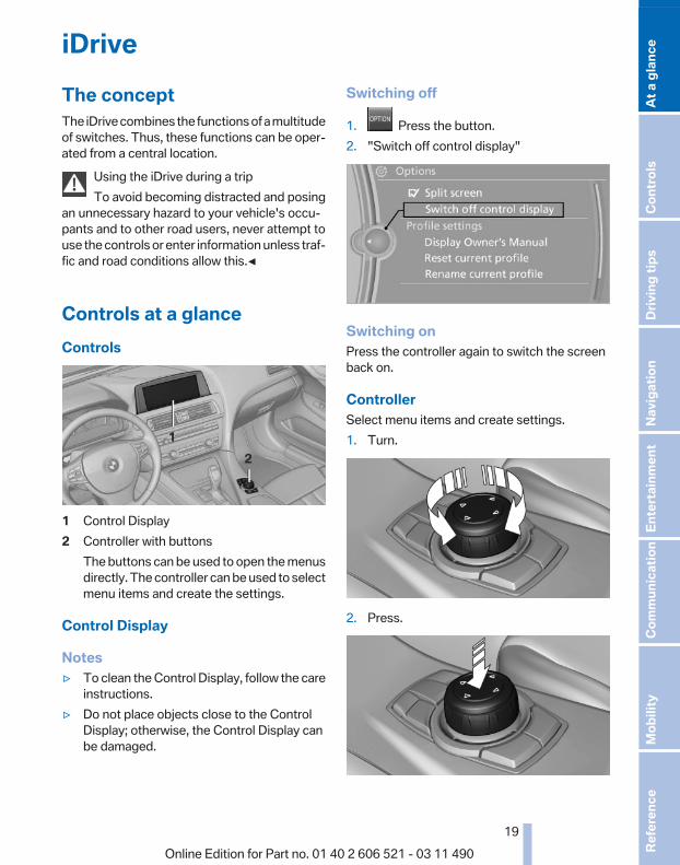
iDriveThe conceptThe iDrive combines the functions of a multitudeof switches. Thus, these functions can be oper‐ated from a central location.
Using the iDrive during a tripTo avoid becoming distracted and posing
an unnecessary hazard to your vehicle's occu‐pants and to other road users, never attempt touse the controls or enter information unless traf‐fic and road conditions allow this.◀
Controls at a glanceControls
1 Control Display2 Controller with buttons
The buttons can be used to open the menusdirectly. The controller can be used to selectmenu items and create the settings.
Control Display
Notes▷ To clean the Control Display, follow the care
instructions.▷ Do not place objects close to the Control
Display; otherwise, the Control Display canbe damaged.
Switching off
1. Press the button.2. "Switch off control display"
Switching onPress the controller again to switch the screenback on.
ControllerSelect menu items and create settings.1. Turn.
2. Press.
Seite 19
19Online Edition for Part no. 01 40 2 606 521 - 03 11 490
Re
fere
nce
Mob
ility
Com
mun
icat
ion
Ente
rtain
men
tNa
vigat
ion
Drivi
ng ti
psCo
ntro
lsAt
a gl
ance
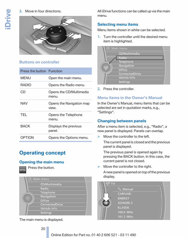
3. Move in four directions.
Buttons on controller
Press the button Function
MENU Open the main menu.
RADIO Opens the Radio menu.
CD Opens the CD/Multimediamenu.
NAV Opens the Navigation mapview.
TEL Opens the Telephonemenu.
BACK Displays the previouspanel.
OPTION Opens the Options menu.
Operating conceptOpening the main menu
Press the button.
The main menu is displayed.
All iDrive functions can be called up via the mainmenu.
Selecting menu itemsMenu items shown in white can be selected.
1. Turn the controller until the desired menuitem is highlighted.
2. Press the controller.
Menu items in the Owner's ManualIn the Owner's Manual, menu items that can beselected are set in quotation marks, e.g.,"Settings".
Changing between panelsAfter a menu item is selected, e.g., "Radio", anew panel is displayed. Panels can overlap.▷ Move the controller to the left.
The current panel is closed and the previouspanel is displayed.The previous panel is opened again bypressing the BACK button. In this case, thecurrent panel is not closed.
▷ Move the controller to the right.A new panel is opened on top of the previousdisplay.
Seite 20
20Online Edition for Part no. 01 40 2 606 521 - 03 11 490
iDriv
e
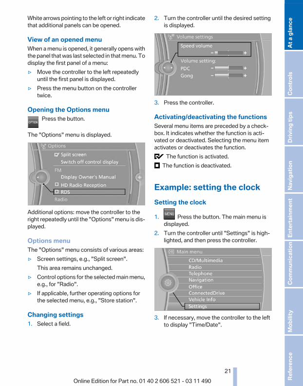
White arrows pointing to the left or right indicatethat additional panels can be opened.
View of an opened menuWhen a menu is opened, it generally opens withthe panel that was last selected in that menu. Todisplay the first panel of a menu:▷ Move the controller to the left repeatedly
until the first panel is displayed.▷ Press the menu button on the controller
twice.
Opening the Options menuPress the button.
The "Options" menu is displayed.
Additional options: move the controller to theright repeatedly until the "Options" menu is dis‐played.
Options menuThe "Options" menu consists of various areas:▷ Screen settings, e.g., "Split screen".
This area remains unchanged.▷ Control options for the selected main menu,
e.g., for "Radio".▷ If applicable, further operating options for
the selected menu, e.g., "Store station".
Changing settings1. Select a field.
2. Turn the controller until the desired settingis displayed.
3. Press the controller.
Activating/deactivating the functionsSeveral menu items are preceded by a check‐box. It indicates whether the function is acti‐vated or deactivated. Selecting the menu itemactivates or deactivates the function.
The function is activated. The function is deactivated.
Example: setting the clockSetting the clock
1. Press the button. The main menu isdisplayed.
2. Turn the controller until "Settings" is high‐lighted, and then press the controller.
3. If necessary, move the controller to the leftto display "Time/Date".
Seite 21
21Online Edition for Part no. 01 40 2 606 521 - 03 11 490
Re
fere
nce
Mob
ility
Com
mun
icat
ion
Ente
rtain
men
tNa
vigat
ion
Drivi
ng ti
psCo
ntro
lsAt
a gl
ance

4. Turn the controller until "Time/Date" is high‐lighted, and then press the controller.
5. Turn the controller until "Time:" is high‐lighted, and then press the controller.
6. Turn the controller to set the hours andpress the controller.
7. Turn the controller to set the minutes andpress the controller.
Status informationStatus fieldThe following information is displayed in the sta‐tus field at the top right:▷ Time.▷ Current entertainment source.▷ Sound output, on/off.▷ Wireless network reception strength.▷ Telephone status.▷ Traffic bulletin reception*.
Status field symbolsThe symbols are grouped as follows.
Radio symbols
Symbol Meaning
Traffic bulletins* are switched on.
HD Radio™* is switched on.
Satellite radio* is switched on.
Telephone symbols
Symbol Meaning
Incoming or outgoing call*.
Missed call*.
Wireless network receptionstrength* Symbol flashes: searchingfor network.
Wireless network is not available*.
Bluetooth* is switched on.
Roaming* is active.
Text message* was received.
Check the SIM card*.
SIM card* is blocked.
SIM card* is missing.
Enter the PIN*.
Entertainment symbols
Symbol Meaning
CD/DVD* player.
Music collection*.
Gracenote® database*.
AUX-IN port.
USB audio interface*.
Mobile phone audio interface*.
Seite 22
22Online Edition for Part no. 01 40 2 606 521 - 03 11 490
iDriv
e

Additional symbols
Symbol Meaning
Spoken instructions* are switchedoff.
Request of the current vehicle posi‐tion*.
Split screen*General informationAdditional information can be displayed on theright side of the split screen, e.g., informationfrom the computer.In the divided screen view, the so-called splitscreen, this information remains visible evenwhen you change to another menu.
Switching the split screen on and off
1. Press the button.2. "Split screen"
Selecting the display
1. Press the button.2. "Split screen"3. Move the controller until the split screen is
selected.4. Press the controller or select "Split screen
content".5. Select the desired menu item.
Programmable memorybuttonsGeneral informationThe iDrive functions can be stored on the pro‐grammable memory buttons and called up di‐rectly, e.g., radio stations, navigation destina‐tions, phone numbers and entry points into themenu.The settings are stored for the remote controlcurrently in use.
Saving a function1. Highlight the function via the iDrive.
2. Press the desired button for morethan 2 seconds.
Running a functionPress the button.The function will run immediately. This
means, for example, that the number is dialedwhen a phone number is selected.
Displaying the button assignmentUse a finger to touch the buttons. Do not weargloves or use objects.The key assignment is displayed at the top edgeof the screen.
▷ To display short information: touch the but‐ton.
▷ To display detailed information: touch thebutton for an extended period.
Seite 23
23Online Edition for Part no. 01 40 2 606 521 - 03 11 490
Re
fere
nce
Mob
ility
Com
mun
icat
ion
Ente
rtain
men
tNa
vigat
ion
Drivi
ng ti
psCo
ntro
lsAt
a gl
ance

Deleting the button assignments1. Press buttons 1 and 8 simultaneously for
approx. five seconds.2. "OK"
Entering letters and numbers1. Turn the controller: select letters or num‐
bers.2. Select additional letters or numbers if
needed.3. "OK": confirm the entry.
Symbol Function
Press the controller: delete the letteror number.
Press the controller for an extendedperiod: delete all letters or numbers.
Enter a blank space.
Switching between letters andnumbersDepending on the menu, you can switch be‐tween entering letters and numbers:
Symbol Function
Enter the letters.
Enter the numbers.
Switching between upper and lowercase lettersDepending on the menu, you can switch be‐tween entering upper and lower case letters:
Symbol Function
Move the controller up: switchfrom upper to lower case letters.
Move the controller up: switchfrom lower to upper case letters.
Entry comparisonEntry of names and addresses: the selection isnarrowed down every time a letter is entered andletters may be added automatically.The entries are continuously compared to thedata stored in the vehicle.▷ Only those letters are offered during the en‐
try for which data is available.▷ Destination search: town/city names can be
entered using the spelling of language avail‐able on the Control Display.
Seite 24
24Online Edition for Part no. 01 40 2 606 521 - 03 11 490
iDriv
e

Voice activation system*The concept▷ The voice activation system can be used to
operate functions by means of spoken com‐mands.
▷ Most menu items on the Control Display canbe voiced as commands. The systemprompts you to make your entries.
▷ Functions that can only be used when thevehicle is stationary cannot be operated us‐ing the voice activation system.
▷ The system uses a special microphone onthe driver's side.
▷ ›...‹ Verbal instructions in the Owner'sManual to use with the voice activation sys‐tem.
RequirementsVia the Control Display, set a language that isalso supported by the voice activation systemso that the spoken commands can be identified.Set the language, refer to page 80.
Using voice activationActivating the voice activation system
1. Press the button on the steeringwheel.
2. Wait for the signal.3. Say the command.
The command is displayed in the instrumentcluster.
This symbol in the instrument cluster indi‐cates that the voice activation system is active.If no other commands are available, continueoperating the function via iDrive.
Terminating the voice activationsystemBriefly press the button on the steering wheelor ›Cancel‹.
Possible commandsHaving possible commands read aloudThe commands available in each case dependon the menu item selected on the Control Dis‐play.To have the available commands read outloud: ›Voice commands‹For example, if the "Settings" menu is displayed,the commands for the settings are read out loud.
Help dialog for the voice activationsystemCalling up help dialog: ›Help‹Additional commands for the help dialog:▷ ›Help with examples‹: information about the
current operating options and the most im‐portant commands for them are announced.
▷ ›Help with voice activation‹: informationabout the principle of operation for the voiceactivation system is announced.
Executing functions using shortcommandsFunctions on the main menu can be performeddirectly by means of short commands, irrespec‐tive of which menu item is currently selected,e.g., ›Vehicle status‹.List of short commands of the voice activationsystem, refer to page 263.
Seite 25
25Online Edition for Part no. 01 40 2 606 521 - 03 11 490
Re
fere
nce
Mob
ility
Com
mun
icat
ion
Ente
rtain
men
tNa
vigat
ion
Drivi
ng ti
psCo
ntro
lsAt
a gl
ance

Example: playing back a CD1. Switch on the Entertainment sound output
if necessary.
2. Press the button on the steeringwheel.
3. ›C D and multimedia‹The medium last played is played back.
4. Press the button on the steeringwheel.
5. ›C D track ...‹ e.g., CD track 4.
Setting the voice dialogYou can set whether the system should use thestandard dialog or a shorter version.In the shorter variant of the voice dialog, the an‐nouncements from the system are issued in anabbreviated form.On the Control Display:
1. "Settings"2. "Language/Units"3. "Speech mode:"4. Select the setting.
Adjusting the volumeTurn the volume button while giving an instruc‐tion until the desired volume is set.▷ The volume remains constant even if the
volume of other audio sources is changed.
▷ The volume is stored for the remote controlcurrently in use.
Notes on EmergencyRequestsDo not use the voice activation system to initiatean Emergency Request. In stressful situations,the voice and vocal pitch can change. This canunnecessarily delay the establishment of a tel‐ephone connection.Instead, use the SOS button*, refer topage 248, in the vicinity of the interior mirror.
Environmental conditions▷ Say the commands, numbers, and letters
smoothly and with normal volume, empha‐sis, and speed.
▷ Always say commands in the language ofthe voice activation system.
▷ When selecting a radio station, use the com‐mon pronunciation of the station name.
▷ Keep the doors, windows, and convertibletop closed to prevent noise interference.
▷ Avoid making other noise in the vehiclewhile speaking.
Seite 26
26Online Edition for Part no. 01 40 2 606 521 - 03 11 490
Voic
e ac
tivat
ion
syst
em

Integrated Owner's Manual in the vehicleThe integrated Owner's Manual can be dis‐played on the Control Display. The equipmentand functions that are in the vehicle are descri‐bed therein.
Components of theintegrated Owner's ManualThe integrated Owner's Manual consists ofthree parts, which offer various levels of infor‐mation or access possibilities.
Quick Reference GuideLocated in the Quick Reference is important in‐formation for the operation of the vehicle, theoperation of basic vehicle functions or for whatto do in the event of a flat tire. This informationcan also be displayed during driving.
Search by picturesInformation and descriptions based on illustra‐tions can be searched via search by pictures.This is helpful, for example, if the description ofan outfitting package that cannot be named isneeded.
Owner's ManualInformation and descriptions can be searchedby direct entry of a search term via the index.
Select components
1. Press the button.2. Turn the controller: open "Vehicle Info".3. Press the controller.4. Selecting desired range:
▷ "Quick reference"▷ "Search by pictures"
▷ "Owner's Manual"
Leafing through the Owner'sManualPage by page with link accessTurn the controller until the next or previouspage is displayed.
Page by page without link accessLeaf through the pages directly while skippingthe links.Highlight the symbol once. Now simply pressthe controller to leaf from page to page.
Leaf back.
Leaf forward.
Context help - Owner'sManual to the temporarilyselected functionThe relevant information can be opened directly.
Opening during operation via iDriveTo move directly from the application on theControl Display to the options menu:
Seite 27
27Online Edition for Part no. 01 40 2 606 521 - 03 11 490
Re
fere
nce
Mob
ility
Com
mun
icat
ion
Ente
rtain
men
tNa
vigat
ion
Drivi
ng ti
psCo
ntro
lsAt
a gl
ance

1. Press the button or move the controllerto the right repeatedly until the "Options"menu is displayed.
2. "Display Owner's Manual"
Opening when a Check Controlmessage is displayedDirectly from the Check Control message on theControl Display:"Display Owner's Manual"
Changing between a function and theOwner's ManualTo change from a function, e.g., radio, to theOwner's Manual on the Control Display and toswitch between the two displays:
1. Press the button or move the controllerto the right repeatedly until the "Options"menu is displayed.
2. "Display Owner's Manual"3. Select the desired page in the Owner's
Manual.
4. Press the button again to return to thefunction displayed last.
5. Press the button to return to the pageof the Owner's Manual displayed last.
To switch back and forth repeatedly betweenthe function displayed last and the page of theOwner's Manual displayed last, repeat steps 4and 5. This opens a new panel every time.
Programmable memorybuttonsGeneral informationThe Owner's Manual can be stored on the pro‐grammable memory buttons and called up di‐rectly.
Storing1. Select "Owner's Manual" via the iDrive.
2. Press the desired button for morethan 2 seconds.
ExecutingPress the button.The Owner's Manual is displayed im‐
mediately.
Seite 28
28Online Edition for Part no. 01 40 2 606 521 - 03 11 490
Inte
grat
ed O
wner
's M
anua
l in th
e ve
hicl
e

Seite 29
29Online Edition for Part no. 01 40 2 606 521 - 03 11 490
Re
fere
nce
Mob
ility
Com
mun
icat
ion
Ente
rtain
men
tNa
vigat
ion
Drivi
ng ti
psCo
ntro
lsAt
a gl
ance

Online Edition for Part no. 01 40 2 606 521 - 03 11 490

ControlsThis chapter is intended to provide you with
information that will give you complete control ofyour vehicle. All features and accessories that are
useful for driving and your safety, comfort andconvenience are described here.
Online Edition for Part no. 01 40 2 606 521 - 03 11 490

Opening and closingRemote control/keyButtons on the remote control
1 Unlocking2 Locking3 Trunk lid4 Panic mode*, headlamp courtesy delay fea‐
ture
General informationThe vehicle is supplied with two remote controlswith keys.Every remote control contains a replaceablebattery.The settings called up and implemented whenthe vehicle is unlocked depend on which remotecontrol is used to unlock the vehicle, PersonalProfile, refer to page 33.In addition, information about service require‐ments is stored in the remote control, Servicedata in the remote control, refer to page 241.
Integrated key
Press the button on the back of the remote con‐trol, arrow 1, and pull out the key, arrow 2.The integrated key fits the following locks:▷ Driver's door.▷ Storage compartment in the center armrest.The storage compartment contains a switch forthe hotel function, refer to page 39.
Replacing the battery
1. Take the integrated key out of the remotecontrol.
2. Push in the catch with the key, arrow 1.3. Remove the cover of the battery compart‐
ment; see arrow 2.4. Insert a battery of the same type with the
positive side facing upwards.5. Press the cover closed.
Take the used battery to a recycling cen‐ter or to your service center.
Seite 32
32Online Edition for Part no. 01 40 2 606 521 - 03 11 490
Open
ing
and
clos
ing

New remote controlsYou can obtain new remote controls from yourservice center.
Loss of the remote controlsLost remote controls can be blocked by yourservice center.
Emergency detection of remote controlIt is possible to switch on the ignition or start theengine in situations such as the following:▷ Interference of radio transmission to remote
control by external sources.▷ Discharged battery in the remote control.A Check Control message is displayed if an at‐tempt is made to switch on the ignition or startthe engine.
Starting the engine in case ofemergency detection of remote control
Automatic transmission: if a correspondingCheck Control message appears, hold the re‐mote control, as shown, against the marked areaon the steering column and press the Start/Stopbutton within 10 seconds while pressing thebrake.Manual transmission: if a corresponding CheckControl message appears, hold the remote con‐trol, as shown, against the marked area on thesteering column and press the Start/Stop buttonwithin 10 seconds while pressing the clutch.
Personal ProfileThe concept
Personal Profile conceptYou can set several of your vehicle's functionsto suit your personal needs and preferences.▷ The settings are automatically saved in the
profile currently activated.▷ When the vehicle is unlocked, the profile that
was last detected and called up with the re‐mote control is used.
▷ Your personal settings will be recognizedand called up again even if the vehicle hasbeen used in the meantime by someone elsewith another remote control.
The individual settings are stored for three Per‐sonal Profiles and one guest profile.
Transmitting the settingsYour personal settings can be taken with you toanother vehicle equipped with the Personal Pro‐file function. For more information, contact yourservice center.Transmission takes place via:▷ The USB interface*, refer to page 132, in
the glove compartment onto a USB device.
Profile management
Opening the profilesA different profile can be called up than the oneassociated with the remote control currently inuse.
1. "Settings"
Seite 33
33Online Edition for Part no. 01 40 2 606 521 - 03 11 490
Re
fere
nce
Mob
ility
Com
mun
icat
ion
Ente
rtain
men
tNa
vigat
ion
Drivi
ng ti
psCo
ntro
lsAt
a gl
ance

2. "Profiles"
3. Select a profile.The profile that is opened is assigned to the re‐mote control currently in use.
Renaming profiles1. "Settings"2. "Profiles"
The current profile is selected.3. Open "Options".4. "Rename current profile"
Resetting profilesThe settings of the active profile are reset totheir default values.
1. "Settings"2. "Profiles"
The current profile is selected.3. Open "Options".4. "Reset current profile"
Importing profilesExisting settings and contacts are overwrittenwith the imported profile.
1. "Settings"2. "Profiles"3. "Import profile"
4. USB interface, refer to page 132: "USBdevice"
Exporting profilesMost settings of the active profile and the savedcontacts can be exported.This can be useful for storing and opening per‐sonal settings, for instance if settings are acci‐dentally changed or deleted.
1. "Settings"2. "Profiles"3. "Export profile"4. USB interface, refer to page 132: "USB
device"
Using the guest profileThe guest profile can be used to make individualsettings without affecting the three PersonalProfiles.This can be useful for drivers who are using thevehicle temporarily and do not have their ownprofile.
1. "Settings"2. "Profiles"3. The current profile is selected.4. Open "Guest".5. Create the settings.Note: the guest profile cannot be renamed.
Seite 34
34Online Edition for Part no. 01 40 2 606 521 - 03 11 490
Open
ing
and
clos
ing

Display profile list during startThe profile list can be displayed during eachstart for selecting the desired profile.
1. "Settings"2. "Profiles"3. Open "Options".4. "Display user list at startup"
Personal Profile settingsThe following functions and settings can bestored in a profile.More information on the settings can be foundunder:▷ Exterior mirror position, refer to page 59.▷ CD/Multimedia, refer to page 173: audio
source listened to last.▷ Dynamic Driving Control: sport program, re‐
fer to page 104.▷ Driver's seat position, refer to page 37: au‐
tomatic retrieval after unlocking.▷ Programmable memory buttons, refer to
page 23: assignment.▷ Head-up Display, refer to page 121: selec‐
tion, brightness and position of the display.▷ Headlamp courtesy delay feature, refer to
page 84: time setting.▷ Tone, refer to page 164: tone settings.▷ Automatic climate control, refer to
page 123: settings.▷ Steering wheel position, refer to page 60.▷ Navigation, refer to page 146: map views,
route criteria, voice output on/off.▷ Night Vision with pedestrian detection, refer
to page 118: selection of functions and typeof display.
▷ Daytime running lights*, refer to page 85:current setting.
▷ Park Distance Control PDC, refer topage 165: adjusting the signal tone volume.
▷ Radio, refer to page 166: stored stations,station listened to last, special settings.
▷ Backup camera, refer to page 110: selec‐tion of functions and type of display.
▷ Side View, refer to page 114: selection ofthe display type.
▷ Language on the Control Display, refer topage 80.
▷ Lane departure warning, refer to page 97:last setting, on/off.
▷ Active Blind Spot Detection, refer topage 98: last setting, on/off.
▷ Triple turn signal activation, refer topage 69.
▷ Locking the vehicle, refer to page 39: aftera brief period or after starting to drive.
Central locking systemThe conceptThe central locking system becomes activewhen the driver's door is closed.The system simultaneously engages and re‐leases the locks on the following:▷ Doors.▷ Compartment in the center armrest.▷ Trunk lid.▷ Fuel filler flap.
Operating from the outside▷ Via the remote control.▷ Via the driver's door lock*.▷ Via the door handles*.▷ Via the button in the trunk lid*.The following takes place simultaneously whenlocking/unlocking the vehicle via the remotecontrol:▷ Anti-theft protection is switched on/off.
Doors cannot be unlocked using the lockbuttons or the door opener.
▷ The welcome lamps, interior lamps andcourtesy lamps* are switched on and off.
▷ The alarm system*, refer to page 42, isarmed or disarmed.
Seite 35
35Online Edition for Part no. 01 40 2 606 521 - 03 11 490
Re
fere
nce
Mob
ility
Com
mun
icat
ion
Ente
rtain
men
tNa
vigat
ion
Drivi
ng ti
psCo
ntro
lsAt
a gl
ance

Operating from the inside
Via the button for the central locking system.
If the vehicle has been locked from inside, thefuel filler flap and the compartment in the centerarmrest remain unlocked.If an accident of a certain severity occurs, thecentral locking system unlocks automatically.The hazard warning system and interior lampscome on.
Opening and closing: from theoutsideUsing the remote control
General informationTake the remote control with youPeople or animals left unattended in a
parked vehicle can lock the doors from the in‐side. Always take the remote control with youwhen leaving the vehicle so that the vehicle canthen be opened from the outside.◀
UnlockingPress the button.The vehicle is unlocked.
You can set how the vehicle is to be unlocked.The setting is stored for the remote control cur‐rently in use.
1. "Settings"2. "Door locks"
3. "Unlock button:"
4. Select the desired function:▷ "Driver's door only"
Only the driver's door and the fuel fillerflap are unlocked. Pressing again un‐locks the entire vehicle.
▷ "All doors"The entire vehicle is unlocked.
Convenient openingPress and hold the button on the re‐mote control.
The side windows and the rear window are fullyopened.With Comfort Access*, the remote control canbe used to open the convertible top when in thevicinity of the vehicle.
Press and hold the button on the re‐mote control until the convertible top is
fully opened and the convertible topwell storage cover is fully closed.
Danger of pinchingMonitor the opening process to ensure
that no one becomes trapped; otherwise, inju‐ries may result.◀
Releasing the button stops the motion.Leaving the vicinity of the vehicle stops the mo‐tion of the convertible top.After a short period, the convertible top and theconvertible top well storage cover are loweredslowly. The convertible top and the convertibletop well storage cover are not locked. Press thebutton again until the convertible top operationis completed.
Seite 36
36Online Edition for Part no. 01 40 2 606 521 - 03 11 490
Open
ing
and
clos
ing

LockingPress the button on the remote control.
Do not lock from the outsideDo not lock the vehicle from the outside if
there are people in it, as the vehicle cannot beunlocked from inside without special knowl‐edge.◀
Convenient closing*With Comfort Access*, the remote control canbe used to close the convertible top, the sidewindows, and the rear window when in the vi‐cinity of the vehicle.
Hold down the remote control button untilthe closing operation is completed.
The convertible top, the side windows, and therear window close.
Monitor the closing processMonitor the closing process to ensure that
no one becomes trapped.◀
Releasing the button or leaving the vicinity of thevehicle stops the motion.After a short period, the convertible top and theconvertible top well storage cover are loweredslowly. The convertible top and the convertibletop well storage cover are not locked. Press thebutton again until the convertible top operationis completed.
Switching on the interior lamps,courtesy lamps*, and welcome lamps
Press the button on the remote controlwith the vehicle locked.
Panic mode*You can trigger the alarm system if you findyourself in a dangerous situation.
Press the button on the remote controlfor at least 3 seconds.
To switch off the alarm: press any button.
Switching on the headlamp courtesydelay feature
Briefly press the button on the remotecontrol.
The duration can be set in the Control Display.
Opening the trunk lidPress the button on the remote controlfor approx. 1 second and release.
The trunk lid opens, regardless of whether it waspreviously locked or unlocked.In some vehicle equipment variants, the trunk lidcan only be opened using the remote control ifthe vehicle was unlocked first.To avoid locking yourself out of the vehicle, donot place the remote control into the cargo area.The trunk lid is locked again as soon as it ispushed closed.
Confirmation signals from the vehicle1. "Settings"2. "Door locks"3. Deactivate or activate the desired confirma‐
tion signals.▷ "Acoustic sig. lock/unlock"▷ "Flash when lock/unlock"
Retrieving the seat, mirror, andsteering wheel settingsThe driver's seat, exterior mirror, and steeringwheel positions selected last are stored for thecurrently used remote control.When the vehicle is unlocked, these positionsare automatically retrieved if this function wasactivated.
Seite 37
37Online Edition for Part no. 01 40 2 606 521 - 03 11 490
Re
fere
nce
Mob
ility
Com
mun
icat
ion
Ente
rtain
men
tNa
vigat
ion
Drivi
ng ti
psCo
ntro
lsAt
a gl
ance

Pinch hazard when moving back the seatIf this function is used, first make sure that
the footwell behind the driver's seat is empty.Otherwise, people can be injured or objectsdamaged when the seat is moved back.◀
The adjustment procedure is interrupted:▷ When a seat position switch is pressed.▷ When a button of the seat, mirror, and steer‐
ing wheel memory is pressed briefly.
Activating the setting1. "Settings"2. "Door locks"3. "Last seat position auto."
MalfunctionIf the vehicle can no longer be locked or un‐locked with the remote control, the battery maybe discharged or there may be interference fromexternal sources such as mobile phones, metalobjects, overhead power lines, transmissiontowers, etc.If this occurs, unlock or lock the vehicle at thedoor lock using the key.
For US owners onlyThe transmitter and receiver units comply withpart 15 of the FCC/Federal CommunicationCommission regulations. Operation is governedby the following:FCC ID:▷ LX8766S.▷ LX8766E.▷ LX8CAS.
▷ LX8CAS2.▷ MYTCAS4.Compliance statement:This device complies with part 15 of the FCCRules. Operation is subject to the following twoconditions:▷ This device may not cause harmful interfer‐
ence, and▷ this device must accept any interference re‐
ceived, including interference that maycause undesired operation.
Any unauthorized modifications or changes tothese devices could void the user's authority tooperate this equipment.
Using the door lock
General information
Do not lock from the outsideDo not lock the vehicle from the outside if
there are people in it, as the vehicle cannot beunlocked from inside without special knowl‐edge.◀
Remove the key before pulling the doorhandle
Before pulling the outside door handle, removethe key to avoid damaging the paintwork and thekey.◀
In some country-specific versions, the alarmsystem* is triggered if the vehicle is unlocked viathe door lock.
Seite 38
38Online Edition for Part no. 01 40 2 606 521 - 03 11 490
Open
ing
and
clos
ing

Manual operationIf an electrical malfunction occurs, lock or unlockthe vehicle using a key via the door lock on thedriver's door.
Locking the doors and trunk lid atonce*In some vehicle equipment versions, only thedriver's door can be locked via the door lock.To lock all doors and the trunk lid at once:
1. With the doors closed, lock the vehicle usingthe button for the central locking system inthe interior.
2. Unlock and open the driver's or front pas‐senger door.
3. Lock the vehicle.▷ Lock the driver's door using the
integrated key in the door lock, or▷ Press down the lock button of the front
passenger door and close the door fromthe outside.
The fuel filler flap can only be locked using theremote control.
Opening and closing: from theinside
Unlocking and opening*▷ Either unlock the doors together using the
button for the central locking system andthen pull the door handle above the armrestor
▷ Pull the door opener twice individually oneach door: the first time unlocks the door,the second time opens it.
Locking and unlockingPress the button in the vehicle.The doors and the trunk lid are locked
or unlocked when the doors are closed, but theyare not secured against theft.
The fuel filler flap remains unlocked.
Automatic lockingThe setting is stored for the remote control cur‐rently in use.
1. "Settings"2. "Door locks"3. Select the desired function:
▷ "Lock if no door is opened"The vehicle locks automatically after ashort period of time if a door is notopened.
▷ "Lock after start. to drive"The vehicle locks automatically afteryou drive away.
Hotel functionWith the hotel function, the compartment in thecenter armrest and the trunk lid is separatelylatched and decoupled by the central lockingsystem.
Seite 39
39Online Edition for Part no. 01 40 2 606 521 - 03 11 490
Re
fere
nce
Mob
ility
Com
mun
icat
ion
Ente
rtain
men
tNa
vigat
ion
Drivi
ng ti
psCo
ntro
lsAt
a gl
ance
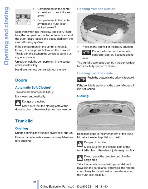
▷ Compartment in the centerarmrest and trunk lid locked,arrow 1.
▷ Compartment in the centerarmrest and trunk lid un‐locked, arrow 2.
Slide the switch into the arrow 1 position. There‐fore, the compartment in the center armrest andthe trunk lid are locked and decoupled from thecentral locking system.If the compartment in the center armrest islocked, it is not possible to open the trunk lid.This is beneficial when the vehicle is parked us‐ing valet service.Unlock or lock the compartment in the centerarmrest with a key.Hand over remote control without the key.
DoorsAutomatic Soft Closing*To close the doors, push lightly.It is closed automatically.
Danger of pinchingMake sure that the closing path of the
doors is clear; otherwise, injuries may result.◀
Trunk lidOpeningDuring opening, the trunk lid pivots back and up.Ensure that adequate clearance is available be‐fore opening.
Opening from the outside
▷ Press on the top half of the BMW emblem.▷ Press the button on the remote
control for approx. 1 second and re‐lease.
The trunk lid cannot be opened if the convertibletop is not fully opened or closed.
Opening from the insidePush the button in the driver's footwell.
If the vehicle is stationary, the trunk lid opens ifit is not locked.
Closing
Recessed grips in the interior trim of the trunklid make it easier to pull down the lid.
Danger of pinchingMake sure that the closing path of the
trunk lid is clear; otherwise, injuries may result.◀
Do not place the remote control in thecargo area
Take the remote control with you and do notleave it in the cargo area; otherwise, the remotecontrol may be locked inside the vehicle whenthe trunk lid is closed.◀
Seite 40
40Online Edition for Part no. 01 40 2 606 521 - 03 11 490
Open
ing
and
clos
ing

Locking the vehicle*
Press the button on the inside of the trunk lid.The vehicle is locked completely.
Emergency unlocking*
Pull the handle inside the cargo area.The trunk lid unlocks.
Comfort Access*The conceptThe vehicle can be accessed without activatingthe remote control.All you need to do is to have the remote controlwith you, e.g., in your jacket pocket.The vehicle automatically detects the remotecontrol when it is nearby or in the passengercompartment.Comfort Access supports the following func‐tions:▷ Unlocking/locking of the vehicle.▷ Convenient closing.▷ Unlocking of the trunk lid separately.▷ Starting the engine.
Functional requirements▷ There are no external sources of interfer‐
ence nearby.▷ To lock the vehicle, the remote control must
be located outside of the vehicle.▷ The next unlocking and locking cycle is not
possible until after approx. 2 seconds.▷ The engine can only be started if the remote
control is inside the vehicle.
Comparison with ordinary remotecontrolThe functions can be controlled by pressing thebuttons or via Comfort Access.
Unlocking
Fully grasp a door handle, arrow 1. This corre‐sponds to pressing the button.
Locking
Press the area on the door handle, arrow 2, withyour finger for approx. 1 second.This corresponds to pressing the button.To save battery power, ensure that the ignitionand all electronic systems and/or power con‐
Seite 41
41Online Edition for Part no. 01 40 2 606 521 - 03 11 490
Re
fere
nce
Mob
ility
Com
mun
icat
ion
Ente
rtain
men
tNa
vigat
ion
Drivi
ng ti
psCo
ntro
lsAt
a gl
ance

sumers are switched off before locking the ve‐hicle.
Convenient closingPress the area, arrow 2, with your finger andhold.In addition to locking, the convertible top, theside windows, and the rear window close as well.Press the area, arrow 2, and hold until the con‐vertible top is fully closed.
Monitor the closing processMonitor the closing process to ensure that
no one becomes trapped.◀
Releasing the area, arrow 2, stops the motion.After a short period, the convertible top and theconvertible top well storage cover are loweredslowly. The convertible top and the convertibletop well storage cover are not locked. Press thearea, arrow 2, again until the convertible top op‐eration is completed.
Unlocking the trunk lid separatelyPress on the top half of the BMW emblem on thetrunk lid.This corresponds to pressing the button.
Do not place the remote control in thecargo area
Take the remote control with you and do notleave it in the cargo area; otherwise, the remotecontrol may be locked inside the vehicle whenthe trunk lid is closed.◀
MalfunctionComfort Access may not function properly if itexperiences interference from external sourcessuch as mobile phones, metal objects, overheadpower lines, transmission towers, etc.If this occurs, open or close the vehicle using thebuttons on the remote control or use a key in thedoor lock.To subsequently start the engine, hold the re‐mote control against the marked area on thesteering column, refer to page 33.
Alarm system*The conceptThe vehicle alarm system responds to:▷ Opening of a door, the hood or the trunk lid.▷ Movements in the vehicle: interior motion
sensor, refer to page 43.▷ Changes in the vehicle tilt, e.g., during at‐
tempts to steal a wheel or when towing thecar.
▷ Interruptions in battery voltage.The alarm system briefly indicates tampering:▷ By sounding an acoustic alarm.▷ By switching on the hazard warning system.▷ By flashing the high beams.
Arming and disarming the alarmsystem
General informationWhen you lock or unlock the vehicle, either withthe remote control or at the door lock*, the alarmsystem is armed or disarmed at the same time.
Door lock and armed alarm systemUnlocking via the door lock will trigger the alarmon some country-specific versions.
Trunk lid and armed alarm systemThe trunk lid can be opened using the remotecontrol, even if the alarm system is armed.
Press the button on the remote controlfor approx. 1 second and release.
After the trunk lid is closed, it is locked andmonitored again by the alarm system. The haz‐ard warning system flashes once.In some vehicle equipment variants, the trunk lidcan only be opened using the remote control ifthe vehicle was unlocked first.
Panic mode*Press the button on the remote controlfor at least 3 seconds.
Seite 42
42Online Edition for Part no. 01 40 2 606 521 - 03 11 490
Open
ing
and
clos
ing

Switching off the alarm▷ Unlock the vehicle using the remote control.▷ With Comfort Access: If you are carrying the
remote control with you, pull on the doorhandle.
Indicator lamp on the interior rearviewmirror
▷ The indicator lamp flashes briefly every2 seconds:The system is armed.
▷ The indicator lamp flashes after locking:The doors, hood or trunk lid is not closedproperly, but the rest of the vehicle is se‐cured.After 10 seconds, the indicator lamp flashescontinuously. The interior motion sensor isnot active.
▷ The indicator lamp goes out after unlocking:The vehicle has not been tampered with.
▷ The indicator lamp flashes after unlockinguntil the engine is started, but no longer thanapprox. 5 minutes:An alarm has been triggered.
Tilt alarm sensorThe tilt of the vehicle is monitored.The alarm system responds in situations suchas attempts to steal a wheel or tow the car.
Interior motion sensorThe interior is monitored to the height of the seatcushions. The alarm system is armed togetherwith the interior motion sensor even when the
convertible top is open. Falling objects such asleaves can trigger the alarm unintentionally.
Avoiding unintentional alarmsThe tilt alarm sensor and interior motion sensorcan be switched off together, such as in the fol‐lowing situations:▷ In automatic car washes▷ In duplex garages.▷ During transport on car-carrying trains, at
sea or on a trailer.▷ When animals are to remain in the vehicle.
Switching off the tilt alarm sensor andinterior motion sensor
Press the button on the remote controltwice in succession.
The indicator lamp lights up for approx. 2 sec‐onds and then flashes continuously.The tilt alarm sensor and interior motion sensorare switched off until the vehicle is locked again.
Power windowsGeneral information
Take the remote control with youTake the remote control with you when
leaving the vehicle so that children, for example,cannot operate the power windows and injurethemselves.◀
Closing the windows when drivingTo close the side windows when driving,
first close the rear windows or all four windowsat the same time; otherwise, the windows maynot close tightly at high speeds.◀
Seite 43
43Online Edition for Part no. 01 40 2 606 521 - 03 11 490
Re
fere
nce
Mob
ility
Com
mun
icat
ion
Ente
rtain
men
tNa
vigat
ion
Drivi
ng ti
psCo
ntro
lsAt
a gl
ance

Opening individually
▷ Press the switch to the resistancepoint.The window opens while the switch is held.
▷ Press the switch beyond the resist‐ance point.The window opens automatically.
Pressing again stops the motion.
Closing individuallyDanger of pinchingMonitor the closing process and make
sure that the closing path of the window is clear;otherwise, injuries may result.◀
▷ Pull the switch to the resistance point.The window closes while the switch is held.
▷ Pull the switch beyond the resistancepoint.The window closes automatically.
Pressing the switch stops the motion.Convenient operation, refer to page 36, via theremote control.Convenient closing, refer to page 42, with Com‐fort Access*.
Opening/closing together
▷ Press the switch to the resistancepoint.All side windows open while the switch isbeing pressed.
Similarly, the windows close while theswitch is being pulled.
▷ Press the switch beyond the resist‐ance point.All side windows open automatically.Pressing again stops the motion.Similarly, the windows are automaticallyclosed when the switch is pulled past theresistance point.
Rear window
Opening
▷ Press the switch to the resistancepoint.The rear window opens while the switch isbeing held.
▷ Press the switch beyond the resist‐ance point.The rear window opens automatically.Pressing again stops the motion.
The rear window opens and closes automati‐cally when the convertible top is opened orclosed.
ClosingPull the switch.The rear window closes while the switch
is being held.
Pinch protectionIf the closing force exceeds a specific value as awindow closes, the closing action is interrupted.The window reopens slightly.The rear window is not equipped with pinch pro‐tection.
Danger of pinching even with pinch pro‐tection
Even with the pinch protection system, checkthat the window's closing path is clear; other‐
Seite 44
44Online Edition for Part no. 01 40 2 606 521 - 03 11 490
Open
ing
and
clos
ing

wise, the closing action may not stop in certainsituations, e.g., if thin objects are present.◀
Window accessoriesDo not install any accessories in the range
of movement of the windows; otherwise, thepinch protection system will be impaired.◀
Closing without the pinch protectionsystem
Danger of pinchingMonitor the closing process and make
sure that the closing path of the window is clear;otherwise, injuries may result.◀
For example, if there is an external danger or ifice on the windows prevents a window fromclosing normally, proceed as follows:
1. Pull the switch past the resistance point andhold it there.Pinch protection is limited and the windowreopens slightly if the closing force exceedsa certain value.
2. Pull the switch past the resistance pointagain within approx. 4 seconds and hold itthere.The window closes without pinch protec‐tion.
Convertible topGeneral informationThe convertible top can be opened or closed atspeeds up to approx. 25 mph/40 km/h.If the vehicle is accelerated above a speed ofapprox. 30 mph/50 km/h while the convertibletop is being moved, the convertible top move‐ment stops.Tips about the convertible top:▷ If possible, close the convertible top when
the vehicle is parked. A closed convertibletop protects it from weather-related dam‐age and to some extent from theft.
▷ Event when the convertible top is closed,only store valuables in the locked cargo area.
▷ At higher speeds, vacuum produced in thepassenger compartment cause the conver‐tible top to begin to flatten. Increase theamount of air via the automatic climate con‐trol so that no vacuum is produced in the ve‐hicle.
NotesThe trunk lid cannot be opened if the convertibletop is not fully opened or closed.
Safety information about the convertibletop
▷ With temperatures below +14 ℉/-10 ℃ donot open the convertible top; otherwisedamages could result.
▷ Do not leave the open convertible top in theconvertible top well longer than one daywhile the top is still wet; otherwise, damagecould result due to moisture.
▷ The convertible top pivots up during open‐ing and closing. When the top is moved, e.g.in garages, make sure that there is a mini‐mum height of 79 inches/2 meters; other‐wise, it damages may result.
▷ Do not place any objects on the convertibletop, otherwise, they could fall and causedamage or injuries.
▷ When the rollover protection system is ex‐tended, do not under any circumstancesmove the convertible top.
▷ Always open or close the convertible topcompletely. Convertible top and convertibletop well storage cover are locked in the finalpositions. Driving with the convertible topeor convertible top well storage cover un‐locked can result in damage.
▷ Do not reach into the convertible top mech‐anism during the opening and closing oper‐ation. Keep children away from the openingpath of the convertible top, otherwise, thereis a risk of injury.
Seite 45
45Online Edition for Part no. 01 40 2 606 521 - 03 11 490
Re
fere
nce
Mob
ility
Com
mun
icat
ion
Ente
rtain
men
tNa
vigat
ion
Drivi
ng ti
psCo
ntro
lsAt
a gl
ance
▷ When the convertible top is opened duringdriving, be alert to traffic; otherwise, it mayresult in an accident. If possible, do not movethe convertible top while driving in reversebecause rearward vision is severely im‐paired while the convertible top is in motion.During windy conditions, do not operate theconvertible top while driving. Do not drivefaster than 30 mph/50 km/h; otherwise, ve‐hicle damage may occur.
▷ Do not attach any roof carrier systems; oth‐erwise, an accident may occur.◀
Functional requirementsThe ignition or radio ready state must beswitched on.It is not possible to start the engine and operatethe convertible top simultaneously. When theengine is started, the convertible top movementis briefly interrupted.Under the following conditions, the convertibletop movement cannot be moved and a CheckControl message is displayed.▷ Cargo area partition is flipped up.▷ Trunk lid is open.▷ External temperature is too low.▷ Vehicle system too low.▷ Convertible top drive is overheating.▷ Movement of the convertible top not al‐
lowed because of national regulations.▷ Vehicle speed is too high.
Before opening and closing▷ Follow the safety instructions for the con‐
vertible top.▷ Make sure that the cargo area partition in the
cargo area is folded down.▷ Make sure that the cargo does not push
against the cargo area partition from below.▷ Make sure that the trunk lid is closed.
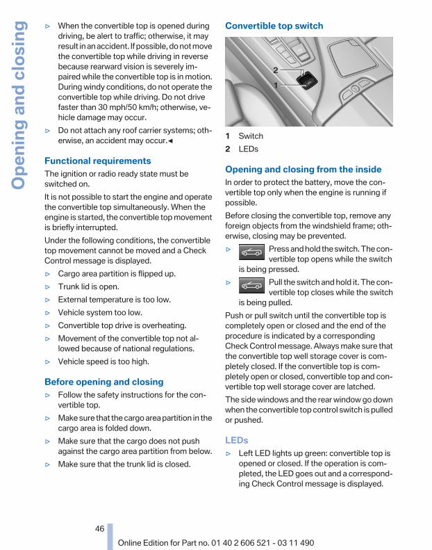
Convertible top switch
1 Switch2 LEDs
Opening and closing from the insideIn order to protect the battery, move the con‐vertible top only when the engine is running ifpossible.Before closing the convertible top, remove anyforeign objects from the windshield frame; oth‐erwise, closing may be prevented.▷ Press and hold the switch. The con‐
vertible top opens while the switchis being pressed.
▷ Pull the switch and hold it. The con‐vertible top closes while the switch
is being pulled.Push or pull switch until the convertible top iscompletely open or closed and the end of theprocedure is indicated by a correspondingCheck Control message. Always make sure thatthe convertible top well storage cover is com‐pletely closed. If the convertible top is com‐pletely open or closed, convertible top and con‐vertible top well storage cover are latched.The side windows and the rear window go downwhen the convertible top control switch is pulledor pushed.
LEDs▷ Left LED lights up green: convertible top is
opened or closed. If the operation is com‐pleted, the LED goes out and a correspond‐ing Check Control message is displayed.
Seite 46
46Online Edition for Part no. 01 40 2 606 521 - 03 11 490
Open
ing
and
clos
ing

▷ Right LED flashes red after the switch is re‐leased: operating sequence has not yet con‐cluded.
▷ Right LED comes on red when the switch ispulled: cargo area partition is flipped up,trunk lid is not closed or there is a malfunc‐tion. Convertible top cannot be moved.
In addition to the red LED, a check control mes‐sage is displayed.
InterruptionAlways open/close the convertible topcompletely
A convertible top that is not opened or closedcompletely is not locked and represents a haz‐ard.◀
The convertible top movement is interrupted ifthe switch is released. The sequence can becontinued in the desired direction using theswitch.If there is a longer interruption, convertible topand convertible top well storage cover remainapprox. 10 minutes in the current position be‐fore they slowly go down. The convertible topand the convertible top well storage cover arenot locked. Operate switch again until the con‐vertible operation is terminated.
Convenient operation* from outsideWhen equipped with Comfort Access* the con‐vertible top can also be operated from outside:▷ Convenient opening with remote operation,
refer to page 36.▷ Convenient closing with the remote control,
refer to page 37.▷ Convenient closing via the door handles, re‐
fer to page 42.
Cargo area partition
Fold down cargo area partition in the back sothat the convertible top can be opened.Fold down cargo area partition in the front in or‐der to enlarge the cargo area space when theconvertible top is closed.
Manually close convertible topIf there is a defect, the convertible top can bemanually closed. Two persons are necessary todo this.
Do not manually open convertible top andclose it manually only in emergency situa‐
tions.Do not manually open the convertible top. Theconvertible top well storage cover cannot latchif there is an electrical defect and would openduring driving.Manually close the convertible top only in emer‐gency situations.Damage can result from improper handling.◀
ToolsTools for manually closing the convertible topare located in the insert of the rear seat backrestunder the first aid kit.
1. Remove insert, refer to page 249.2. Remove the first aid kit.3. Remove tools.
Seite 47
47Online Edition for Part no. 01 40 2 606 521 - 03 11 490
Re
fere
nce
Mob
ility
Com
mun
icat
ion
Ente
rtain
men
tNa
vigat
ion
Drivi
ng ti
psCo
ntro
lsAt
a gl
ance

1 Convertible top tool2 Adapter3 Rear window tool
Before closing1. Open trunk lid, refer to page 40.
Depending on the reason for the defect, itmay be the case that the trunk lid cannot beopened. Then the convertible top cannot bemanually closed.
2. Remove the two large caps from the trim. Ifnecessary, use a screwdriver to help withthis.
3. Unlock convertible top well storage cover.To do this, pull on the right cap and simul‐taneously slightly raise the front right con‐vertible top well storage cover in front of therear window.Proceed accordingly on the left side.
4. When the convertible top is closed man‐ually, the trunk lid can no longer be opened.Remove urgently needed items from thecargo area and close the trunk lid.
5. Lower the side window and the rear windowcompletely.If the rear window cannot be lowered elec‐trically, it must be lowered manually.
Manually lowering rear windowThe spindle for lowering the rear window is lo‐cated in front of the rear window in the centerbeneath the convertible top well storage cover.
1. Have a second person slightly raise the con‐vertible top well storage cover, arrow 1, andhold it.
2. Insert the rear window tool through the fun‐nel-shaped opening into the spindle, ar‐row 2. Turn the spindle clockwise, arrow 3,until the rear window is all the way down.
Lifting out convertible topOnly close the convertible top with twopeople
Carry out the following steps with the aid of asecond person and with the doors open; other‐wise, it may result in damage to the convertibletop.◀
Seite 48
48Online Edition for Part no. 01 40 2 606 521 - 03 11 490
Open
ing
and
clos
ing

1. Grasp the convertible top well storage coveron both sides, swing it up until it reaches itslimit position and hold it in place.
2. Remove the cover in the center of the frontconvertible top frame. If necessary, use ascrewdriver to help with this.
3. Insert the convertible top tool into the con‐vertible top lock. Turn the convertible toptool approx. one half turn clockwise to openthe convertible top lock. Be careful not todamage the convertible top fabric. Removethe convertible top tool.
4. On both sides of the vehicle, grasp the frontedge of the convertible top frame with onehand. With the other hand, grasp the end ofthe convertible top on the bottom edge.
Keep the convertible top well storage coveropen, e.g. with your shoulder.
5. Lift out the convertible top and the conver‐tible top ends on both sides simultaneouslyand swing it forward. When you do this,make sure that the convertible top ends donot push against other parts.
Seite 49
49Online Edition for Part no. 01 40 2 606 521 - 03 11 490
Re
fere
nce
Mob
ility
Com
mun
icat
ion
Ente
rtain
men
tNa
vigat
ion
Drivi
ng ti
psCo
ntro
lsAt
a gl
ance
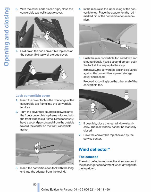
6. With the cover ends placed high, close theconvertible top well storage cover.
7. Fold down the two convertible top ends onthe convertible top well storage cover.
Lock convertible cover1. Insert the cover tool on the front edge of the
convertible top frame into the convertibletop lock.
2. Turn the cover tool counterclockwise untilthe front convertible top frame is locked withthe front windshield frame. Simultaneously,have a second person push from the outsidetoward the center on the front windshieldframe.
3. Insert the convertible top tool with the longend into the adapter from the tool kit.
4. In the rear, raise the inner lining of the con‐vertible top. Place the adapter on the red-marked pin of the convertible top mecha‐nism.
5. Push the rear convertible top end down andsimultaneously have a second person pushthe tool all the way up to the stop.In this way, the convertible top end is pushedagainst the convertible top well storagecover and locked.Proceed accordingly on the other end of theconvertible top.
6. If possible, close the rear window electri‐cally. The rear window cannot be manuallyclosed.
7. Have the convertible top checked by theservice center.
Wind deflector*The conceptThe wind deflector reduces the air movement inthe passenger compartment when driving withthe top down.
Seite 50
50Online Edition for Part no. 01 40 2 606 521 - 03 11 490
Open
ing
and
clos
ing

Installation1. Remove wind deflector from the protective
jacket and unfold it.
2. Press the upper and lower parts togetheruntil the latch engages.
3. Push out the right retaining pin until the latchengages and flip out the two rear retainingpins.
4. Install the wind deflector on the vehicle withthe right retaining pin and the two rear onesin the corresponding openings.
5. Push the left retaining pin into the providedopening until it latches.
6. Flip up the top half of the wind deflector.
Do not tilt the front seat backrest too farback
Do not tilt the front seat backrest too far backwith the wind deflector installed if the seat is tobe moved all the way back. Otherwise, the winddeflector will be damaged.◀
RemovingProceed in reverse sequence.
Seite 51
51Online Edition for Part no. 01 40 2 606 521 - 03 11 490
Re
fere
nce
Mob
ility
Com
mun
icat
ion
Ente
rtain
men
tNa
vigat
ion
Drivi
ng ti
psCo
ntro
lsAt
a gl
ance

To release the two lateral retaining pins, pull thecorresponding handle forward a little and thempull it to the side.
Folding up
On the left side, pull the handle of the retainingpin on the wind deflector all the way back andrelease the latch. Fold in top and bottom part.
Seite 52
52Online Edition for Part no. 01 40 2 606 521 - 03 11 490
Open
ing
and
clos
ing

AdjustingSitting safelyThe ideal seating position can make a vital con‐tribution to relaxed, fatigue-free driving.The seating position plays an important role inan accident in combination with:▷ Safety belts, refer to page 56.▷ Head restraints, refer to page 57.▷ Airbags, refer to page 88.
SeatsAdjusting
General informationDo not adjust the seat while drivingNever attempt to adjust the driver's seat
while driving.The seat could respond with unexpected move‐ment and the ensuing loss of vehicle controlcould lead to an accident.◀
Do not incline the backrest too far to therear
Do not incline the backrest on the front passen‐ger side too far to the rear during driving. Oth‐erwise, there is the danger of sliding under thesafety belt in an accident. This would eliminatethe protection normally provided by the belt.◀
The seat setting is stored for the remote controlcurrently in use. When the vehicle is unlockedvia the remote control, the position is automati‐cally retrieved if this function, refer to page 37,was activated.
At a glance
1 Active seat*2 Seat, mirror, and steering wheel memory*3 Backrest width*4 Lumbar support*5 Backrest, head restraint*6 Shoulder support*7 Forward/back, height, tilt*8 Thigh support*
Adjustments in detail1. Forward/back.
2. Height.
Seite 53
53Online Edition for Part no. 01 40 2 606 521 - 03 11 490
Re
fere
nce
Mob
ility
Com
mun
icat
ion
Ente
rtain
men
tNa
vigat
ion
Drivi
ng ti
psCo
ntro
lsAt
a gl
ance
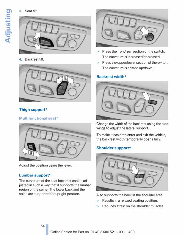
3. Seat tilt.
4. Backrest tilt.
Thigh support*
Multifunctional seat*
Adjust the position using the lever.
Lumbar support*The curvature of the seat backrest can be ad‐justed in such a way that it supports the lumbarregion of the spine. The lower back and thespine are supported for upright posture.
▷ Press the front/rear section of the switch.The curvature is increased/decreased.
▷ Press the upper/lower section of the switch.The curvature is shifted up/down.
Backrest width*
Change the width of the backrest using the sidewings to adjust the lateral support.
To make it easier to enter and exit the vehicle,the backrest width temporarily opens fully.
Shoulder support*
Also supports the back in the shoulder area:▷ Results in a relaxed seating position.▷ Reduces strain on the shoulder muscles.
Seite 54
54Online Edition for Part no. 01 40 2 606 521 - 03 11 490
Adju
stin
g

Active seat*Active adjustment of the seat cushion's con‐tours reduces muscular tension and fatigue tohelp prevent lower back pain.
Press the button. The LED lights up.
Front seat heating*
Switching onPress the button once for each temper‐ature level.
The maximum temperature is reached whenthree LEDs are lit.
Switching offPress the button longer.The LEDs go out.The temperature may be reduced or seat heat‐ing may be switched off entirely to save batterypower.
Temperature distribution*The heating action in the seat cushion and back‐rest can be distributed in different ways.
1. "Climate"2. "Seat heating distribution"
3. Select the required seat.
4. Turn the controller to set the temperaturedistribution.
Front active seat ventilation*The seat cushion and backrest surfaces arecooled by means of integrated fans.The ventilation rapidly cools the seat, e.g., if thevehicle interior is overheated or for continuouscooling at high temperatures.
Switching onPress the button once for each ventila‐tion level.
The highest level is active when three LEDs arelit.
After a short time, the system automaticallymoves down one level in order to prevent ex‐cessive cooling.
Switching offPress the button longer.The LEDs go out.
Seite 55
55Online Edition for Part no. 01 40 2 606 521 - 03 11 490
Re
fere
nce
Mob
ility
Com
mun
icat
ion
Ente
rtain
men
tNa
vigat
ion
Drivi
ng ti
psCo
ntro
lsAt
a gl
ance

Safety beltsSeats with safety beltThe vehicle has four seats, each of which isequipped with a safety belt.
NotesAlways make sure that safety belts are beingworn by all occupants before driving away.Although airbags enhance safety by providingadded protection, they are not a substitute forsafety belts.
One person per safety beltNever allow more than one person to wear
a single safety belt. Never allow infants or smallchildren to ride on a passenger's lap.◀
Putting on the beltLay the belt, without twisting, snugly
across the lap and shoulders, as close to thebody as possible. Make sure that the belt lies lowaround the hips in the lap area and does notpress on the abdomen. Otherwise, the belt canslip over the hips in the lap area in a frontal im‐pact and injure the abdomen.The safety belt must not lie across the neck, rubon sharp edges, be routed over solid or breaka‐ble objects, or be pinched.◀
Reduction of restraining effectAvoid wearing clothing that prevents the
belt from fitting properly, and pull the shoulderbelt periodically to readjust the tension acrossyour lap; otherwise, the retention effect of thesafety belt may be reduced.◀
Buckling the belt
Make sure you hear the latch plate engage in thebelt buckle.
Unbuckling the belt1. Hold the belt firmly.2. Press the red button in the belt buckle.3. Guide the belt back into its reel.
Safety belt reminder for the driver's andfront passenger seat
The indicator lamp flashes or lights upand a signal sounds. Make sure that thesafety belts are positioned correctly.
The safety belt reminder is active at speedsabove approx. 5 mph/8 km/h. It can also be ac‐tivated if objects are placed on the front pas‐senger seat.
Damage to safety beltsIn the case of strain caused by accidents ordamage:Have the safety belts, including the safety belttensioners, replaced and have the belt anchorschecked.
Checking and replacing safety beltsHave the work performed only by your
service center; otherwise, it cannot be ensuredthat this safety feature will function properly.◀
Seite 56
56Online Edition for Part no. 01 40 2 606 521 - 03 11 490
Adju
stin
g

Front head restraintsCorrectly adjusted head restraintA correctly adjusted head restraint reduces therisk of injury to cervical vertebrae in the event ofan accident.
Adjusting the head restraintCorrectly adjust the head restraints of all
occupied seats; otherwise, there is an increasedrisk of injury in an accident.◀
HeightAdjust the head restraint so that its center is ap‐proximately at ear level.
DistanceAdjust the distance so that the head restraint isas close as possible to the back of the head.
Active head restraintIn the event of a rear-end collision with a certainseverity, the active head restraint automaticallyreduces the distance from the head.
Reduced protective function▷ Do not use seat or head restraint cov‐
ers.▷ Do not hang objects, e.g., clothes hangers,
on the head restraints.▷ Only attach accessories approved by BMW
to the seat or head restraint.Otherwise, the protective function of the activehead restraint will be impaired and the personalsafety of the occupants will be endangered.◀
Adjusting the height*
Adjusting electrically.
Distance to the back of the head*
▷ Forward: pull.▷ Back: press the button and push the head
restraint toward the rear.
Adjusting the side extensions*
Fold forward for increased lateral support in theresting position.
RemovingThe head restraints cannot be removed.
Seite 57
57Online Edition for Part no. 01 40 2 606 521 - 03 11 490
Re
fere
nce
Mob
ility
Com
mun
icat
ion
Ente
rtain
men
tNa
vigat
ion
Drivi
ng ti
psCo
ntro
lsAt
a gl
ance

Entering the rearNote
Folding back and locking the backrestBefore driving away, fold back and lock the
backrests; otherwise, an unexpected seatmovement may cause an accident.◀
Unlocking the backrest
Pull the lever and fold the backrest forward.
Changing the seat position
To change the entry area:▷ Press and hold the button until the seat has
moved to the desired position. Releasingthe button stops the motion.
▷ Press the button briefly. The seat automat‐ically moves to the respective end position.Pressing again stops the motion.
Folding back and locking the backrestAfter entering the rear, fold the backrest backand lock it.
Press the button. The seat moves to itsoriginal position. Pressing again stops themotion.
Seat, mirror, and steeringwheel memory*General information
Two different driver's seat, exterior mirror, andsteering wheel positions can be stored and re‐trieved for each remote control. The adjustmentof the lumbar support is not stored.
Storing1. Switch on the ignition.2. Set the desired position.
3. Press the button. The LED in thebutton lights up.
4. Press the desired button 1 or 2. The LEDgoes out.
If the M button is pressed accidentally:Press the button again.The LED goes out.
Calling up settingsDo not retrieve the memory while drivingDo not retrieve the memory setting while
driving, as an unexpected movement of the seator steering wheel could result in an accident.◀
Comfort function1. Open the driver's door.2. Switch off the ignition.3. Briefly press the desired button 1 or 2.The corresponding seat position is performedautomatically.
Seite 58
58Online Edition for Part no. 01 40 2 606 521 - 03 11 490
Adju
stin
g
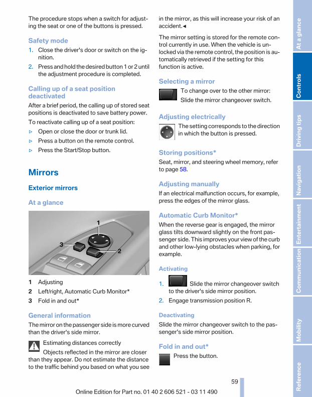
The procedure stops when a switch for adjust‐ing the seat or one of the buttons is pressed.
Safety mode1. Close the driver's door or switch on the ig‐
nition.2. Press and hold the desired button 1 or 2 until
the adjustment procedure is completed.
Calling up of a seat positiondeactivatedAfter a brief period, the calling up of stored seatpositions is deactivated to save battery power.To reactivate calling up of a seat position:▷ Open or close the door or trunk lid.▷ Press a button on the remote control.▷ Press the Start/Stop button.
MirrorsExterior mirrors
At a glance
1 Adjusting2 Left/right, Automatic Curb Monitor*3 Fold in and out*
General informationThe mirror on the passenger side is more curvedthan the driver's side mirror.
Estimating distances correctlyObjects reflected in the mirror are closer
than they appear. Do not estimate the distanceto the traffic behind you based on what you see
in the mirror, as this will increase your risk of anaccident.◀
The mirror setting is stored for the remote con‐trol currently in use. When the vehicle is un‐locked via the remote control, the position is au‐tomatically retrieved if the setting for thisfunction is active.
Selecting a mirrorTo change over to the other mirror:Slide the mirror changeover switch.
Adjusting electricallyThe setting corresponds to the directionin which the button is pressed.
Storing positions*Seat, mirror, and steering wheel memory, referto page 58.
Adjusting manuallyIf an electrical malfunction occurs, for example,press the edges of the mirror glass.
Automatic Curb Monitor*When the reverse gear is engaged, the mirrorglass tilts downward slightly on the front pas‐senger side. This improves your view of the curband other low-lying obstacles when parking, forexample.
Activating
1. Slide the mirror changeover switchto the driver's side mirror position.
2. Engage transmission position R.
DeactivatingSlide the mirror changeover switch to the pas‐senger's side mirror position.
Fold in and out*Press the button.
Seite 59
59Online Edition for Part no. 01 40 2 606 521 - 03 11 490
Re
fere
nce
Mob
ility
Com
mun
icat
ion
Ente
rtain
men
tNa
vigat
ion
Drivi
ng ti
psCo
ntro
lsAt
a gl
ance

Possible up to approx. 15 mph/20 km/h.For example, this is advantageous▷ In car washes.▷ In narrow streets.▷ For folding back mirrors that were folded
away manually.Mirrors that were folded in are folded out auto‐matically at a speed of approx. 25 mph/40 km/h.
Fold in the mirror in a car washBefore entering an automatic car wash,
fold in the exterior mirrors by hand or with thebutton; otherwise, they could be damaged, de‐pending on the width of the vehicle.◀
Automatic heatingBoth exterior mirrors are automatically heatedwhenever the engine is running.
Automatic dimming featureBoth exterior mirrors are automatically dimmed.Photocells are used for control in the Interior rearview mirror, refer to page 60.
Interior rearview mirror
Reducing the blinding effect
From behind when driving at night: turn theknob.
Interior rearview mirror, automaticdimming feature*
Photocells are used for control:▷ In the mirror glass.▷ On the back of the mirror.For proper operation:▷ Keep the photocells clean.▷ Do not cover the area between the inside
rearview mirror and the windshield.
Steering wheelGeneral information
Do not adjust while drivingDo not adjust the steering wheel while
driving; otherwise, an unexpected movementcould result in an accident.◀
Seite 60
60Online Edition for Part no. 01 40 2 606 521 - 03 11 490
Adju
stin
g

Adjusting
The steering wheel can be adjusted in four di‐rections.
Storing the positionSeat, mirror, and steering wheel memory, referto page 58.
Assistance getting in and outThe steering wheel temporarily moves into thehighest position to make it easier to enter andexit the vehicle.
Steering wheel heating*
Switching on/offPress the button.
▷ On: the LED lights up.▷ Off: the LED goes out.
Seite 61
61Online Edition for Part no. 01 40 2 606 521 - 03 11 490
Re
fere
nce
Mob
ility
Com
mun
icat
ion
Ente
rtain
men
tNa
vigat
ion
Drivi
ng ti
psCo
ntro
lsAt
a gl
ance

Transporting children safelyThe right place for childrenNote
Children in the vehicleDo not leave children unattended in the
vehicle; otherwise, they could endanger them‐selves and other persons, e.g., by opening thedoors.◀
Children should always be in the rearAccident research shows that the safest placefor children is in the back seat.
Transporting children in the rearOnly transport children younger than
13 years of age or shorter than 5 ft/150 cm in therear in child restraint fixing systems provided inaccordance with the age, weight and size of thechild; otherwise, there is an increased risk of in‐jury in an accident.Children 13 years of age or older must wear asafety belt as soon as a suitable child restraintfixing system can no longer be used, due to theirage, weight and size.◀
Children on the front passenger seatShould it ever be necessary to use a child re‐straint fixing system in the front passenger seat,make sure that the front, knee and side airbagson the front passenger side are deactivated. Au‐tomatic deactivation of front passenger airbags,refer to page 89.
Deactivating the front passenger airbagsIf a child restraint fixing system is used in
the front passenger seat, the front passengerairbags must be deactivated; otherwise, there isan increased risk of injury to the child when theairbags are triggered, even with a child restraintfixing system.◀
Installing child restraint fixingsystemsNotes
Manufacturer's information for child re‐straint fixing systems
To select, mount and use child restraint fixingsystems, observe the information provided bythe system manufacturer; otherwise, the pro‐tective effect can be impaired.◀
On the front passenger seatAfter installing a child restraint fixing system inthe front passenger seat, make sure that thefront, knee and side airbags on the front pas‐senger side are deactivated.Deactivate the front passenger airbags auto‐matically, refer to page 89.
Deactivating the front passenger airbagsIf a child restraint fixing system is used in
the front passenger seat, the front passengerairbags must be deactivated; otherwise, there isan increased risk of injury to the child when theairbags are triggered, even with a child restraintfixing system.◀
Seat position and heightBefore installing a child restraint fixing system,move the front passenger seat as far back aspossible and adjust its height to the highest po‐sition to obtain the best possible position for thebelt and to offer optimal protection in the eventof an accident.Do not change the seat position and height afterthis.
Backrest width*Before installing a child restraint fixing system inthe front passenger seat, open the backrestwidth completely. Do not change the backrest
Seite 62
62Online Edition for Part no. 01 40 2 606 521 - 03 11 490
Tran
spor
ting
child
ren
safe
ly

width again and do not call up a memory posi‐tion.
Backrest width for the child seatBefore installing a child restraint fixing
system in the front passenger seat, the backrestwidth must be opened completely. Do notchange the adjustment after this; otherwise, thestability of the child seat will be reduced.◀
Child seat security
The rear safety belts and the front passengersafety belt can be locked against pulling out formounting the child restraint fixing systems.
Locking the safety belt1. Pull out the belt webbing completely.2. Secure the child restraint fixing system with
the belt.3. Allow the belt webbing to be pulled in and
pull it taut against the child restraint fixingsystem. The safety belt is locked.
Unlocking the safety belt1. Unbuckle the belt buckle.2. Remove the child restraint fixing system.3. Allow the belt webbing to be pulled in com‐
pletely.
LATCH child restraint fixingsystemLATCH: Lower Anchors and Tether for CHil‐dren.
NoteManufacturer's information for LATCHchild restraint fixing systems
To mount and use the LATCH child restraint fix‐ing systems, observe the operating and safetyinformation from the system manufacturer; oth‐erwise, the level of protection may be reduced.◀
Mounts for the lower LATCH anchorsCorrectly engage the lower LATCH an‐chors
Make sure that the lower LATCH anchors haveproperly engaged and that the child restraint fix‐ing system is resting snugly against the back‐rest; otherwise, the degree of protection offeredmay be reduced.◀
Before mounting the LATCH child restraint fix‐ing system, pull the belt away from the child re‐straint fixing system.
Mounts for the lower LATCH anchors are lo‐cated in the gap between the seat and backrest.
Mounting LATCH child restraint fixingsystems1. Mount the child restraint fixing system; refer
to the operating instructions of the system.2. Ensure that both LATCH anchors are prop‐
erly connected.
Child restraint fixing system with atether strap
For Canadian customers OnlyThe following statement is required by Trans‐port Canada:
Seite 63
63Online Edition for Part no. 01 40 2 606 521 - 03 11 490
Re
fere
nce
Mob
ility
Com
mun
icat
ion
Ente
rtain
men
tNa
vigat
ion
Drivi
ng ti
psCo
ntro
lsAt
a gl
ance

This vehicle is not equipped with user-readytether anchorages. As such neither a child re‐straint system, nor a booster cushion, requirer‐ing the use of a tether strap can be properly se‐cured in the vehicle.
Seite 64
64Online Edition for Part no. 01 40 2 606 521 - 03 11 490
Tran
spor
ting
child
ren
safe
ly

DrivingStart/Stop buttonThe concept
Pressing the Start/Stop buttonswitches the ignition on or off andstarts the engine.Automatic transmission*: the en‐gine starts if the brake is de‐
pressed when the Start/Stop button is pressed.Manual transmission: the engine starts if theclutch is depressed when the Start/Stop buttonis pressed.
Ignition onAutomatic transmission*: press the Start/Stopbutton, and do not press on the brake pedal atthe same time.Manual-shift transmission: press the Start/Stopbutton, and do not press on the clutch pedal atthe same time.All vehicle systems are ready for operation.Most of the indicator and warning lamps in theinstrument cluster light up for varying lengths oftime.To save battery power when the engine is off,switch off the ignition and any unnecessaryelectronic systems/power consumers.The ignition switches off automatically:▷ When the vehicle is locked, if the low beams
are switched on.▷ Shortly before the battery is discharged
completely, so that the engine can still bestarted.
▷ If the engine is switched off and the ignitionis switched on, the system automaticallyswitches to the radio ready state when thedoor is opened if the lights are switched offor the daytime running lights are switchedon.
Ignition offAutomatic transmission*: press the Start/Stopbutton again, and do not press on the brakepedal at the same time.Manual-shift transmission: press the Start/Stopbutton again, and do not press on the clutchpedal at the same time.All indicator lamps in the instrument cluster goout.To save battery power when the engine is off,switch off the ignition and any unnecessaryelectronic systems/power consumers.
Transmission position P with the ignitionoff
When the ignition is switched off, position P isengaged automatically. When in an automaticcar wash, for example, ensure that the ignition isnot switched off accidentally.◀
When the vehicle is locked using the centrallocking system, the ignition switches off auto‐matically.
Radio ready stateActivate radio ready state:▷ When the ignition is switched off: press ON/
OFF button on the radio.▷ When the engine is running: press START/
STOP button.Some electronic systems/power consumers re‐main ready for operation.Radio ready state switches off automatically:▷ After approx. 8 minutes.▷ When the vehicle is locked using the central
locking system.
Seite 65
65Online Edition for Part no. 01 40 2 606 521 - 03 11 490
Re
fere
nce
Mob
ility
Com
mun
icat
ion
Ente
rtain
men
tNa
vigat
ion
Drivi
ng ti
psCo
ntro
lsAt
a gl
ance

Starting the engineGeneral information
Enclosed areasDo not let the engine run in enclosed
areas; otherwise, breathing of exhaust fumesmay lead to loss of consciousness and death.The exhaust gases contain carbon monoxide, anodorless and colorless but highly toxic gas.◀
Unattended vehicleDo not leave the car unattended with the
engine running; otherwise, it presents a poten‐tial source of danger.Before leaving the car with the engine running,set the parking brake and place the transmissionin position P or neutral to prevent the car frommoving.◀
Frequent starting in quick successionAvoid repeated futile attempts at starting
the car and avoid starting the car frequently inquick succession. Otherwise, the fuel is notburned or is inadequately burned, and there isthe danger of overheating and damaging thecatalytic converter.◀
Do not wait for the engine to warm up while thevehicle remains stationary. Start driving at mod‐erate engine speeds.
Manual transmission
Starting the engine1. Depress the brake pedal.2. Press on the clutch and shift to neutral.3. Press the Start/Stop button.The ignition is activated automatically for a cer‐tain time and is stopped as soon as the enginestarts.
Automatic transmission*
Starting the engine1. Depress the brake pedal.2. Press the Start/Stop button.
The ignition is activated automatically for a cer‐tain time and is stopped as soon as the enginestarts.
Engine stopGeneral information
Take the remote control with youTake the remote control with you when
leaving the vehicle so that children, for example,cannot operate the windows and injure them‐selves.◀
Set the parking brake and further securethe vehicle as required
Set the parking brake firmly when parking; oth‐erwise, the vehicle could roll. On steep upwardand downward inclines, further secure the vehi‐cle, for example, by turning the steering wheel inthe direction of the curb. ◀
Before driving into a car washIn order for the vehicle to be able to roll into a carwash, heed the information regarding Washingin automatic car washes, refer to page 254.
Manual transmission
Switching off the engine1. With the vehicle at a standstill, press the
Start/Stop button.2. Shift into first gear or reverse.3. Set the parking brake.
Automatic transmission*
Switching off the engine1. Engage transmission position P with the ve‐
hicle stopped.2. Press the Start/Stop button.
The engine is switched off.The radio ready state is switched on.
3. Set the parking brake.
Seite 66
66Online Edition for Part no. 01 40 2 606 521 - 03 11 490
Drivi
ng
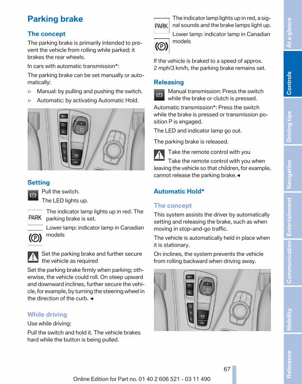
Parking brakeThe conceptThe parking brake is primarily intended to pre‐vent the vehicle from rolling while parked; itbrakes the rear wheels.In cars with automatic transmission*:The parking brake can be set manually or auto‐matically:▷ Manual: by pulling and pushing the switch.▷ Automatic: by activating Automatic Hold.
SettingPull the switch.The LED lights up.
The indicator lamp lights up in red. Theparking brake is set.Lower lamp: indicator lamp in Canadianmodels
Set the parking brake and further securethe vehicle as required
Set the parking brake firmly when parking; oth‐erwise, the vehicle could roll. On steep upwardand downward inclines, further secure the vehi‐cle, for example, by turning the steering wheel inthe direction of the curb. ◀
While drivingUse while driving:Pull the switch and hold it. The vehicle brakeshard while the button is being pulled.
The indicator lamp lights up in red, a sig‐nal sounds and the brake lamps light up.Lower lamp: indicator lamp in Canadianmodels
If the vehicle is braked to a speed of approx.2 mph/3 km/h, the parking brake remains set.
ReleasingManual transmission: Press the switchwhile the brake or clutch is pressed.
Automatic transmission*: Press the switchwhile the brake is pressed or transmission po‐sition P is engaged.The LED and indicator lamp go out.
The parking brake is released.Take the remote control with youTake the remote control with you when
leaving the vehicle so that children, for example,cannot release the parking brake.◀
Automatic Hold*
The conceptThis system assists the driver by automaticallysetting and releasing the brake, such as whenmoving in stop-and-go traffic.The vehicle is automatically held in place whenit is stationary.On inclines, the system prevents the vehiclefrom rolling backward when driving away.
Seite 67
67Online Edition for Part no. 01 40 2 606 521 - 03 11 490
Re
fere
nce
Mob
ility
Com
mun
icat
ion
Ente
rtain
men
tNa
vigat
ion
Drivi
ng ti
psCo
ntro
lsAt
a gl
ance

For your safetyUnder the following conditions, Automatic Holdis automatically deactivated and the parkingbrake is set:▷ The engine is switched off.▷ A door is opened and driver's safety belt is
unbuckled.▷ The moving vehicle is brought to a standstill
using the parking brake.The indicator lamp switches from greento red and the letters AUTO H go out.Lower lamp: indicator lamp in Canadianmodels
Before driving away:▷ Release the parking brake manually.▷ Reactivate Automatic Hold.
Leaving the vehicle with the engine run‐ning
Before leaving the vehicle with the engine run‐ning, engage position P of the automatic trans‐mission and ensure that the parking brake is set.Otherwise, the vehicle may begin to roll.◀
ActivatingThis function can be activated when the driver'sdoor is closed and the safety belt is fastened, orwhile driving.
Press the button.The LED and the letters AUTO H light
up.
The indicator lamp lights up.Automatic Hold is activated.
DeactivatingPress the button again.The LED and the letters AUTO H go
out.
Automatic Hold is deactivated.If the vehicle is being held by Automatic Hold,press on the brake pedal to deactivate it.
When the parking brake, refer to page 67, is setmanually, Automatic Hold is deactivated auto‐matically.
DrivingAutomatic Hold is activated: the vehicle is auto‐matically secured against rolling when it stops.
The indicator lamp lights up in green.Step on the accelerator pedal to driveoff.The brake is released automatically.The indicator lamp goes out.
Lower lamp: indicator lamp in Canadian models
Before driving into a car washDeactivate Automatic Hold; otherwise, the
parking brake will be set when the vehicle is sta‐tionary and the vehicle will no longer be able toroll.◀
ParkingThe parking brake is automatically set if the en‐gine is switched off while the vehicle is beingheld by Automatic Hold.
The indicator lamp changes from greento red.The parking brake is not set if the engineis switched off while the vehicle is coast‐ing to a halt. Automatic Hold is deacti‐vated.
Lower lamp: indicator lamp in Canadian models
Take the remote control with youTake the remote control with you when
leaving the vehicle so that children, for example,cannot release the parking brake.◀
MalfunctionIn the event of a failure or malfunction of theparking brake, secure the vehicle against rollingusing a wheel chock, for example, when leavingit.
Seite 68
68Online Edition for Part no. 01 40 2 606 521 - 03 11 490
Drivi
ng

Turn signal, high beams,headlamp flasherTurn signal
Using turn signals
Press the lever beyond the resistance point.To switch off manually, press the lever to the re‐sistance point.
Unusually rapid flashing of the indicator lamp in‐dicates that a turn signal bulb has failed.
Triple turn signal activationPress the lever to the resistance point.The turn signal flashes three times.The function can be activated or deactivated:
1. "Settings"2. "Lighting"3. "Triple turn signal"
Signaling brieflyPress the lever to the resistance point and holdit there for as long as you want the turn signal toflash.
High beams, headlamp flasher
▷ High beams, arrow 1.▷ Headlamp flasher, arrow 2.
Washer/wiper systemSwitching the wipers on/off and briefwipe
Do not switch on the wipers if frozenDo not switch on the wipers if they are fro‐
zen onto the windshield; otherwise, the wiperblades and the windshield wiper motor may bedamaged.◀
Switching on
Press the wiper levers up.The lever automatically returns to its initial po‐sition when released.▷ Normal wiping speed: press up once.
The wipers switch to intermittent operationwhen the vehicle is stationary.
▷ Fast wiping speed: press up twice or pressonce beyond the resistance point.The wipers switch to normal speed when thevehicle is stationary.
Seite 69
69Online Edition for Part no. 01 40 2 606 521 - 03 11 490
Re
fere
nce
Mob
ility
Com
mun
icat
ion
Ente
rtain
men
tNa
vigat
ion
Drivi
ng ti
psCo
ntro
lsAt
a gl
ance

Switching off and brief wipe
Press the wiper levers down.The lever automatically returns to its initial po‐sition when released.▷ Brief wipe: press down once.▷ To switch off normal wipe: press down once.▷ To switch off fast wipe: press down twice.
Rain sensor
The conceptThe time between wipes is controlled automat‐ically and depends on the intensity of the rainfall.The sensor is located on the windshield, directlyin front of the interior rearview mirror.
Activating/deactivating the rain sensor
Press the button on the wiper lever.When activated, the wipers move over the wind‐shield once.The LED in the steering column stalk lights up.
Deactivate the rain sensor in car washesDeactivate the rain sensor when passing
through an automatic car wash; otherwise, dam‐age could be caused by undesired wiper activa‐tion.◀
Rain sensor sensitivity
Turn the thumbwheel.
Clean the windshield, headlamps*
Pull the lever.The system sprays washer fluid on the wind‐shield and activates the wipers briefly.
In addition, the headlamps are cleaned at regularintervals when the vehicle lights are switchedon.
Do not use the washer system at freezingtemperatures
Do not use the washers if there is any dangerthat the fluid will freeze on the windshield; oth‐erwise, your vision could be obscured. For thisreason, use antifreeze.Avoid using the washer when the reservoir isempty; otherwise, you could damage thepump.◀
Seite 70
70Online Edition for Part no. 01 40 2 606 521 - 03 11 490
Drivi
ng

Windshield washer nozzlesThe washer jets are automatically heated*whenever the ignition is switched on.
Fold-out position of the wipersRequired when changing the wiper blades orunder frosty conditions, for example.
1. Switch off the ignition.2. Under frosty conditions, ensure that the
wiper blades are not frozen onto the wind‐shield.
3. Press the wiper lever up beyond the point ofresistance and hold it for approx. 3 seconds,until the wiper remains in a nearly verticalposition.
After the wipers are folded back down, the wipersystem must be reactivated.
Fold the wipers back downBefore switching the ignition on, fold the
wipers back down to the windshield; otherwise,the wipers may become damaged when they areswitched on.◀
1. Switch on the ignition.2. Press the wiper levers down. The wipers
move to their resting position and are readyfor operation.
Washer fluidGeneral information
Antifreeze for washer fluidAntifreeze is flammable. Therefore, keep
it away from sources of ignition.Only keep it in the closed original container andinaccessible to children.Follow the instructions on the container.◀
Washer fluid reservoirAdding washer fluidOnly add washer fluid when the engine is
cool, and then close the cover completely toavoid contact between the washer fluid and hotengine parts.Otherwise, there is the danger of fire and a riskto personal safety if the fluid is spilled.◀
All washer nozzles are supplied from one reser‐voir.Fill with water and – if required – with a washerantifreeze, according to the manufacturer's rec‐ommendations.Mix the washer fluid before adding to maintainthe correct mixing ratio.
CapacityApprox. 5.3 US quarts/ 5 liters
Manual transmissionShifting
Shifting into 5th or 6th gearWhen shifting into 5th or 6th gear, push
the gearshift lever to the right; otherwise inad‐vertent shifting into the 3rd or 4th gear couldlead to engine damage.◀
Reverse gearSelect only when the vehicle is stationary. Whenthe gearshift lever is pressed to the left, a slightresistance needs to be overcome.
Seite 71
71Online Edition for Part no. 01 40 2 606 521 - 03 11 490
Re
fere
nce
Mob
ility
Com
mun
icat
ion
Ente
rtain
men
tNa
vigat
ion
Drivi
ng ti
psCo
ntro
lsAt
a gl
ance

Automatic transmission withSteptronic*Transmission positions
D Drive, automatic positionPosition for normal vehicle operation. All for‐ward gears are available.
R is ReverseSelect only when the vehicle is stationary.
N is NeutralUse in automatic car washes, for example. Thevehicle can roll.When the ignition is switched off, refer topage 65, position P is engaged automatically.
P ParkSelect only when the vehicle is stationary. Thedrive wheels are blocked.P is engaged automatically:▷ After the engine is switched off, if the car is
in radio ready state, refer to page 65, or if theignition is switched off, refer to page 65, andif position R or D is engaged.
▷ If the ignition is switched off and position Nis engaged.
▷ If the safety belt is unbuckled, the driver'sdoor is opened, and the brake pedal is notpressed while the vehicle is stationary andtransmission position R or D is engaged.
KickdownKickdown is used to achieve maximum drivingperformance. Press on the accelerator beyondthe resistance point at the full throttle position.
Engaging the transmission position▷ Transmission position P can only be disen‐
gaged if the engine is running and the brakepedal is pressed.
▷ With the vehicle stationary, press on thebrake pedal before shifting out of P or N;
otherwise, the shift command will not beexecuted: shift lock.
Depress the brake until you start driv‐ing
To prevent the vehicle from creeping afteryou select a driving position, maintain pres‐sure on the brake pedal until you are readyto start.◀
Engaging D, R and N
Briefly push the selector lever in the desired di‐rection, beyond a resistance point if necessary.After releasing the selector lever, it returns to itscenter position.
Press the Unlock button to:▷ Engage R.▷ Shift out of P.
Seite 72
72Online Edition for Part no. 01 40 2 606 521 - 03 11 490
Drivi
ng

Engaging P
Press button P.
Sport program and manual mode M/S
Activating the sport program
Push the selector lever to the left out of trans‐mission position D.DS is displayed in the instrument cluster.This position is recommended for a perform‐ance-oriented driving style.
Activating the M/S manual modePush the selector lever to the left out of trans‐mission position D.Push the selector lever forward or backward.Manual mode becomes active and the gear ischanged.The engaged gear is displayed in the instrumentcluster, e.g., M1.▷ To shift down: press the selector lever for‐
ward.▷ To shift up: press the selector lever back‐
ward.The transmission only shifts up or down if therpm and vehicle speed are appropriate. If the
engine speed is too high, the transmission doesnot shift down.The selected gear is briefly displayed in the in‐strument cluster, followed by the current gear.
Ending the sport program/manualmodePush the selector lever to the right.D is displayed in the instrument cluster.
Shift paddles for Sport automatictransmission*
The shift paddles on the steering wheel allowyou to shift gears quickly while keeping bothhands on the steering wheel.If the shift paddles on the steering wheel areused to shift gears in automatic mode, the trans‐mission temporarily switches to manual mode.If the shift paddles are not used and the vehicleis not accelerated for a certain time, the systemswitches back into automatic mode if the selec‐tor lever is in D.▷ Shift up: pull right shift paddle.▷ Shift down: pull left shift paddle.The vehicle only shifts up or down at appropriateengine and road speeds, e.g., it does not shiftdown if the engine speed is too high.The selected gear is briefly displayed in the in‐strument cluster, followed by the current gear.
Displays in the instrument clusterThe transmission position is dis‐played, for instance, P.
Seite 73
73Online Edition for Part no. 01 40 2 606 521 - 03 11 490
Re
fere
nce
Mob
ility
Com
mun
icat
ion
Ente
rtain
men
tNa
vigat
ion
Drivi
ng ti
psCo
ntro
lsAt
a gl
ance

DisplaysInstrument clusterAt a glance
1 Fuel gauge2 Speedometer3 Indicator/warning lamps4 Tachometer5 Oil temperature
6 External temperature7 Electronic displays8 Miles, trip miles9 Clock10 Display/reset miles
Fuel gaugeThe vehicle inclination maycause the display to vary.Notes on refueling, refer topage 226.
RangeAfter the reserve range isreached:▷ A Check Control message is
displayed briefly.
▷ The remaining range isshown on the computer.
▷ When a dynamic driving style is used, suchas when corners are taken rapidly, enginefunctions are not ensured.
The Check Control message appears continu‐ously below a range of approx. 30 miles/50 km.
Refuel promptlyRefuel no later than at a range 30 miles/
50 km, or engine functions are not ensured anddamage may occur.◀
Seite 74
74Online Edition for Part no. 01 40 2 606 521 - 03 11 490
Disp
lays
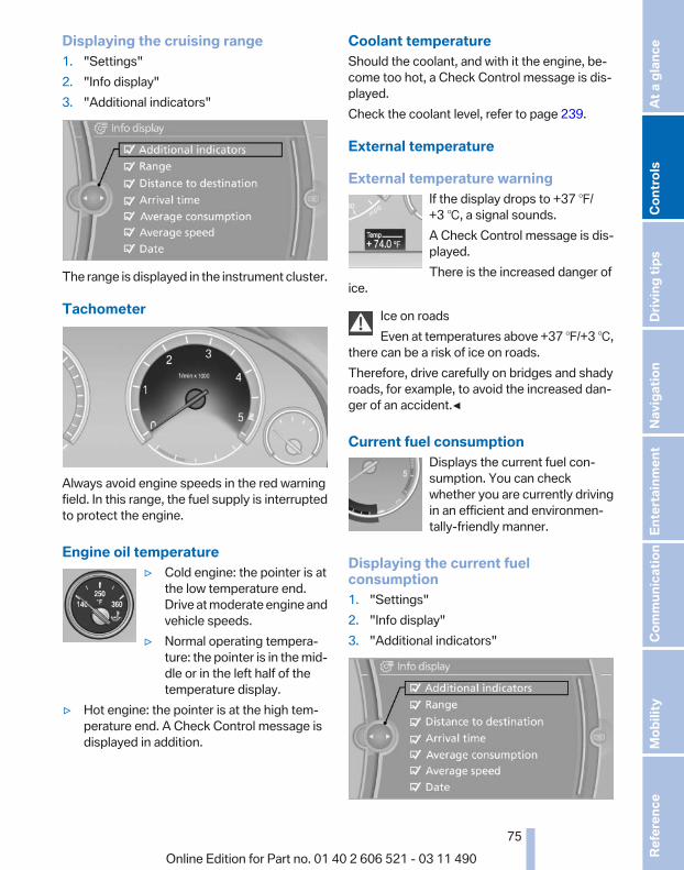
Displaying the cruising range1. "Settings"2. "Info display"3. "Additional indicators"
The range is displayed in the instrument cluster.
Tachometer
Always avoid engine speeds in the red warningfield. In this range, the fuel supply is interruptedto protect the engine.
Engine oil temperature▷ Cold engine: the pointer is at
the low temperature end.Drive at moderate engine andvehicle speeds.
▷ Normal operating tempera‐ture: the pointer is in the mid‐dle or in the left half of thetemperature display.
▷ Hot engine: the pointer is at the high tem‐perature end. A Check Control message isdisplayed in addition.
Coolant temperatureShould the coolant, and with it the engine, be‐come too hot, a Check Control message is dis‐played.Check the coolant level, refer to page 239.
External temperature
External temperature warningIf the display drops to +37 ℉/+3 ℃, a signal sounds.A Check Control message is dis‐played.There is the increased danger of
ice.
Ice on roadsEven at temperatures above +37 ℉/+3 ℃,
there can be a risk of ice on roads.Therefore, drive carefully on bridges and shadyroads, for example, to avoid the increased dan‐ger of an accident.◀
Current fuel consumptionDisplays the current fuel con‐sumption. You can checkwhether you are currently drivingin an efficient and environmen‐tally-friendly manner.
Displaying the current fuelconsumption1. "Settings"2. "Info display"3. "Additional indicators"
Seite 75
75Online Edition for Part no. 01 40 2 606 521 - 03 11 490
Re
fere
nce
Mob
ility
Com
mun
icat
ion
Ente
rtain
men
tNa
vigat
ion
Drivi
ng ti
psCo
ntro
lsAt
a gl
ance

The bar display for the current fuel consumptionis displayed in the instrument cluster.
Energy recoveryThe energy of motion of the ve‐hicle is converted to electrical en‐ergy while coasting. The vehiclebattery is partially charged andfuel consumption can be low‐ered.
Odometer and trip odometer▷ Odometer, arrow 1.▷ Trip odometer, arrow 2.
Display/reset milesPress the knob.▷ When the ignition is switched
off, the time, external temper‐ature and odometer are dis‐played.
▷ When the ignition is switched on, the tripodometer is reset.
TimeThe time is displayed at the bot‐tom of the instrument cluster.Setting the time and time format,refer to page 79.
DateThe date is displayed in the in‐strument cluster.Setting the date and date format,refer to page 80.
Selection lists in theinstrument clusterThe concept
The following can be operated using the buttonsand the thumbwheel on the steering wheel:▷ Current audio source.▷ Redial on telephone*.▷ Activation of the voice activation system*.
Activating a list and creating thesetting
Press a button on the right side of the steeringwheel or turn the thumbwheel to activate the re‐quired list.Create the setting using the thumbwheel.
ComputerIndication in the info display
The information from the com‐puter is shown in the Info displayin the instrument cluster.
Seite 76
76Online Edition for Part no. 01 40 2 606 521 - 03 11 490
Disp
lays

Calling up information on the infodisplay
Press the computer button on the turn signallever.Information is displayed on the info display of theinstrument cluster.
Information at a glanceRepeatedly pressing the button on the turn sig‐nal lever calls up the following information on theinfo display:▷ Range.▷ Average fuel consumption.▷ Average speed.▷ Date*.▷ Time of arrival*
When destination guidance is activated inthe navigation system.
▷ Distance to destination*When destination guidance is activated inthe navigation system.
▷ Arrow view of navigation system*When destination guidance is activated inthe navigation system.
Adjusting the info displayYou can select what information from the com‐puter is to be displayed on the info display of theinstrument cluster.
1. "Settings"2. "Info display"
3. Select the desired displays.
Information in detail
RangeDisplays the estimated cruising range availablewith the remaining fuel.It is calculated based on your driving style overthe last 20 miles/30 km. If there is only enoughfuel left for less than 45 miles/80 km, the colorof the display changes.
Average fuel consumptionThis is calculated for the period during which theengine is running.The average fuel consumption is calculated onthe basis of various distances.
Average speedPeriods in which the vehicle is parked with theengine stopped do not enter into the calculation.
Resetting average valuesPress and hold the computer button on the turnsignal lever.
Distance to destination*The distance remaining to the destination is dis‐played if a destination is entered in the naviga‐tion system* before the trip is started.The distance to the destination is adopted au‐tomatically.
Seite 77
77Online Edition for Part no. 01 40 2 606 521 - 03 11 490
Re
fere
nce
Mob
ility
Com
mun
icat
ion
Ente
rtain
men
tNa
vigat
ion
Drivi
ng ti
psCo
ntro
lsAt
a gl
ance

Time of arrival*The estimated time of arrival isdisplayed if a destination is en‐tered in the navigation system*before the trip is started.The time must be correctly set.
Speed limitDisplay of a speed limit which, when reached,should cause a warning to be issued.Renewed warning if the vehicle speed drops be‐low the set speed limit once by at least 3 mph/5 km/h.
Displaying, setting or changing thelimit1. "Settings"2. "Speed"3. "Warning at:"
4. Turn the controller until the desired limit isdisplayed.
5. Press the controller.The speed limit is stored.
Activating/deactivating the limit1. "Settings"2. "Speed"3. "Warning"4. Press the controller.
Applying your current speed as thelimit1. "Settings"2. "Speed"
3. "Select current speed"4. Press the controller.
The current vehicle speed is stored as thelimit.
Resetting valuesThe average fuel consumption and averagespeed can be reset.Press and hold the computer button on the turnsignal lever.
Trip computerThere are two types of computer.▷ "Onboard info": the values can be reset as
often as necessary.▷ "Trip computer": the values provide an over‐
view of the current trip.
Resetting the trip computer1. "Vehicle Info"2. "Trip computer"3. "Reset": all values are reset.
"Automatically reset": all values are resetapprox. 4 hours after the vehicle comes to astandstill.
Display on the Control DisplayDisplay the computer or trip computer on theControl Display.
1. "Vehicle Info"2. "Onboard info" or "Trip computer"
Seite 78
78Online Edition for Part no. 01 40 2 606 521 - 03 11 490
Disp
lays

Resetting the fuel consumption orspeed1. "Vehicle Info"2. "Onboard info"3. "Cons." or "Speed"
4. "Yes"
Gear shift indicator*The conceptThe system recommends the most fuel efficientgear in the current driving situation.Indicators to shift up or down are displayed inthe instrument cluster.
Displays
1 Fuel efficient gear is engaged2 Shift up to fuel efficient gear3 Shift down to fuel efficient gear
Settings on the ControlDisplayTime
Setting the time zone*1. "Settings"2. "Time/Date"3. "Time zone"4. Select the desired time zone.The time zone is stored.
Setting the time1. "Settings"2. "Time/Date"3. "Time:"
4. Turn the controller until the desired hoursare displayed.
5. Press the controller.6. Turn the controller until the desired minutes
are displayed.7. Press the controller.The time is stored.
Setting the time format1. "Settings"2. "Time/Date"3. "Format:"4. Select the desired format.The time format is stored.
Seite 79
79Online Edition for Part no. 01 40 2 606 521 - 03 11 490
Re
fere
nce
Mob
ility
Com
mun
icat
ion
Ente
rtain
men
tNa
vigat
ion
Drivi
ng ti
psCo
ntro
lsAt
a gl
ance
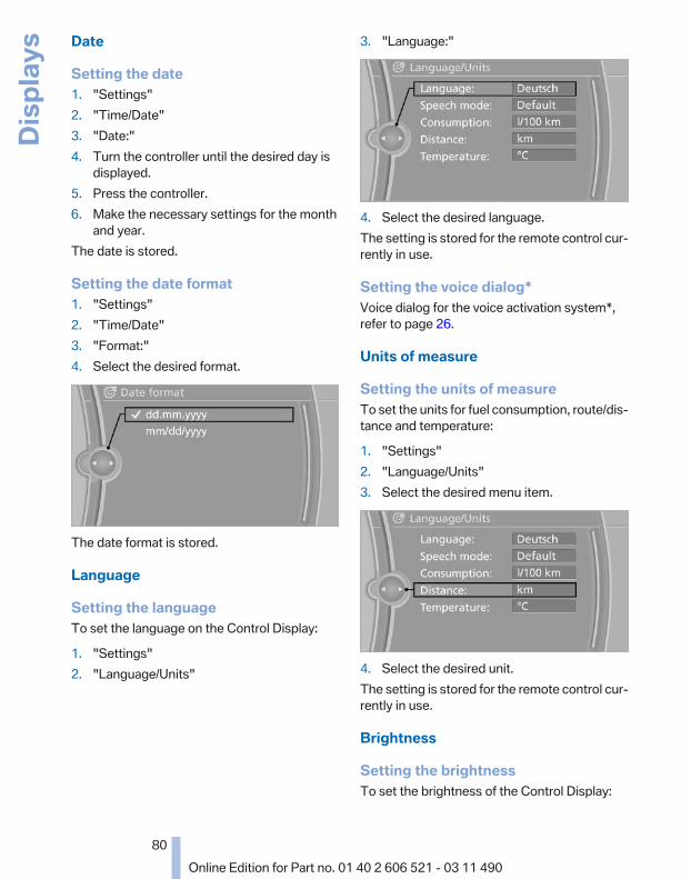
Date
Setting the date1. "Settings"2. "Time/Date"3. "Date:"4. Turn the controller until the desired day is
displayed.5. Press the controller.6. Make the necessary settings for the month
and year.The date is stored.
Setting the date format1. "Settings"2. "Time/Date"3. "Format:"4. Select the desired format.
The date format is stored.
Language
Setting the languageTo set the language on the Control Display:
1. "Settings"2. "Language/Units"
3. "Language:"
4. Select the desired language.The setting is stored for the remote control cur‐rently in use.
Setting the voice dialog*Voice dialog for the voice activation system*,refer to page 26.
Units of measure
Setting the units of measureTo set the units for fuel consumption, route/dis‐tance and temperature:
1. "Settings"2. "Language/Units"3. Select the desired menu item.
4. Select the desired unit.The setting is stored for the remote control cur‐rently in use.
Brightness
Setting the brightnessTo set the brightness of the Control Display:
Seite 80
80Online Edition for Part no. 01 40 2 606 521 - 03 11 490
Disp
lays
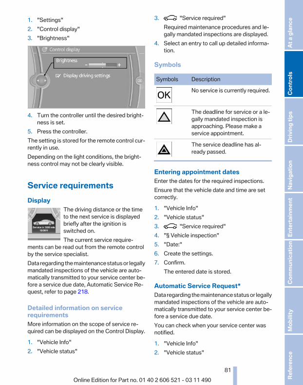
1. "Settings"2. "Control display"3. "Brightness"
4. Turn the controller until the desired bright‐ness is set.
5. Press the controller.The setting is stored for the remote control cur‐rently in use.Depending on the light conditions, the bright‐ness control may not be clearly visible.
Service requirementsDisplay
The driving distance or the timeto the next service is displayedbriefly after the ignition isswitched on.The current service require‐
ments can be read out from the remote controlby the service specialist.Data regarding the maintenance status or legallymandated inspections of the vehicle are auto‐matically transmitted to your service center be‐fore a service due date, Automatic Service Re‐quest, refer to page 218.
Detailed information on servicerequirementsMore information on the scope of service re‐quired can be displayed on the Control Display.
1. "Vehicle Info"2. "Vehicle status"
3. "Service required"Required maintenance procedures and le‐gally mandated inspections are displayed.
4. Select an entry to call up detailed informa‐tion.
Symbols
Symbols Description
No service is currently required.
The deadline for service or a le‐gally mandated inspection isapproaching. Please make aservice appointment.
The service deadline has al‐ready passed.
Entering appointment datesEnter the dates for the required inspections.Ensure that the vehicle date and time are setcorrectly.
1. "Vehicle Info"2. "Vehicle status"3. "Service required"4. "§ Vehicle inspection"5. "Date:"6. Create the settings.7. Confirm.
The entered date is stored.
Automatic Service Request*Data regarding the maintenance status or legallymandated inspections of the vehicle are auto‐matically transmitted to your service center be‐fore a service due date.You can check when your service center wasnotified.
1. "Vehicle Info"2. "Vehicle status"
Seite 81
81Online Edition for Part no. 01 40 2 606 521 - 03 11 490
Re
fere
nce
Mob
ility
Com
mun
icat
ion
Ente
rtain
men
tNa
vigat
ion
Drivi
ng ti
psCo
ntro
lsAt
a gl
ance

3. Open "Options".4. "Last Service Request"
Check ControlThe conceptThe Check Control system monitors functionsin the vehicle and notifies you of malfunctions inthe monitored systems.A Check Control message is displayed as acombination of indicator or warning lamps andtext messages in the instrument cluster and inthe Head-up Display*.In addition, an acoustic signal may be output anda text message may appear on the Control Dis‐play.
Indicator/warning lamps
The indicator and warning lamps can light up ina variety of combinations and colors.Several of the lamps are checked for properfunctioning and light up temporarily when theengine is started or the ignition is switched on.
Text messagesText messages in combination with a symbol inthe instrument cluster explain a Check Controlmessage and the meaning of the indicator andwarning lamps.
Supplementary text messagesAddition information, such as on the cause of afault or the required action, can be called up viaCheck Control. The supplementary text of ur‐gent messages is displayed automatically.
It is shown on the Control Display.
SymbolsDepending on the Check Control message, thefollowing functions can be selected.▷ "Owner's Manual"
Display additional information about theCheck Control message in the integratedowner's manual.
▷ "Service request"Contact the service partner.
▷ "Roadside Assistance"Contact Roadside Assistance.
Hiding Check Control messages
Press the computer button on the turn signallever.
▷ Some Check Control messages are dis‐played continuously and are not cleared un‐til the malfunction is eliminated. If severalmalfunctions occur at once, the messagesare displayed consecutively.These messages can be hidden for approx.8 seconds. After this time, they are dis‐played again automatically.
▷ Other Check Control messages are hiddenautomatically after approx. 20 seconds.They are stored and can be displayed againlater.
Displaying stored Check Controlmessages1. "Vehicle Info"2. "Vehicle status"
Seite 82
82Online Edition for Part no. 01 40 2 606 521 - 03 11 490
Disp
lays
3. "Check Control"4. Select the text message.
Messages after trip completionMalfunctions indicated during a trip are dis‐played again after the ignition is switched off.
Seite 83
83Online Edition for Part no. 01 40 2 606 521 - 03 11 490
Re
fere
nce
Mob
ility
Com
mun
icat
ion
Ente
rtain
men
tNa
vigat
ion
Drivi
ng ti
psCo
ntro
lsAt
a gl
ance
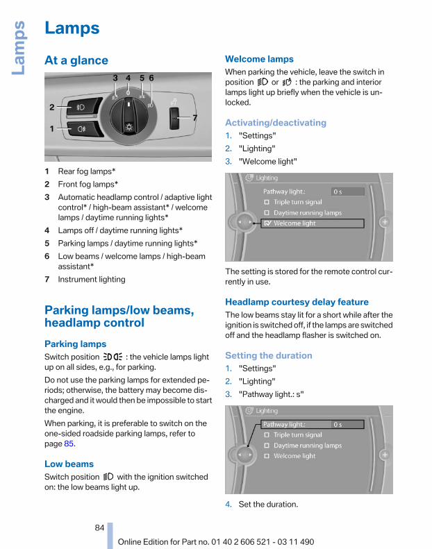
LampsAt a glance
1 Rear fog lamps*2 Front fog lamps*3 Automatic headlamp control / adaptive light
control* / high-beam assistant* / welcomelamps / daytime running lights*
4 Lamps off / daytime running lights*5 Parking lamps / daytime running lights*6 Low beams / welcome lamps / high-beam
assistant*7 Instrument lighting
Parking lamps/low beams,headlamp controlParking lampsSwitch position : the vehicle lamps lightup on all sides, e.g., for parking.Do not use the parking lamps for extended pe‐riods; otherwise, the battery may become dis‐charged and it would then be impossible to startthe engine.When parking, it is preferable to switch on theone-sided roadside parking lamps, refer topage 85.
Low beamsSwitch position with the ignition switchedon: the low beams light up.
Welcome lampsWhen parking the vehicle, leave the switch inposition or : the parking and interiorlamps light up briefly when the vehicle is un‐locked.
Activating/deactivating1. "Settings"2. "Lighting"3. "Welcome light"
The setting is stored for the remote control cur‐rently in use.
Headlamp courtesy delay featureThe low beams stay lit for a short while after theignition is switched off, if the lamps are switchedoff and the headlamp flasher is switched on.
Setting the duration1. "Settings"2. "Lighting"3. "Pathway light.: s"
4. Set the duration.
Seite 84
84Online Edition for Part no. 01 40 2 606 521 - 03 11 490
Lam
ps
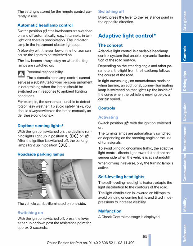
The setting is stored for the remote control cur‐rently in use.
Automatic headlamp controlSwitch position : the low beams are switchedon and off automatically, e.g., in tunnels, in twi‐light or if there is precipitation. The indicatorlamp in the instrument cluster lights up.A blue sky with the sun low on the horizon cancause the lights to be switched on.The low beams always stay on when the foglamps are switched on.
Personal responsibilityThe automatic headlamp control cannot
serve as a substitute for your personal judgmentin determining when the lamps should beswitched on in response to ambient lightingconditions.For example, the sensors are unable to detectfog or hazy weather. To avoid safety risks, youshould always switch on the lamps manually un‐der these conditions.◀
Daytime running lights*With the ignition switched on, the daytime run‐ning lights light up in position 0, or .After the ignition is switched off, the parkinglamps light up in position .
Roadside parking lamps
The vehicle can be illuminated on one side.
Switching onWith the ignition switched off, press the levereither up or down past the resistance point forapprox. 2 seconds.
Switching offBriefly press the lever to the resistance point inthe opposite direction.
Adaptive light control*The conceptAdaptive light control is a variable headlampcontrol system that enables dynamic illumina‐tion of the road surface.Depending on the steering angle and other pa‐rameters, the light from the headlamp followsthe course of the road.In tight curves, e.g., on mountainous roads orwhen turning, an additional, corner-illuminatinglamp is switched on that lights up the inside ofthe curve when the vehicle is moving below acertain speed.
Controls
ActivatingSwitch position with the ignition switchedon.The turning lamps are automatically switchedon depending on the steering angle or the useof turn signals.To avoid blinding oncoming traffic, the adaptivelight control directs light towards the front pas‐senger side when the vehicle is at a standstill.When driving in reverse, only the turning lamp isactive.
Self-leveling headlightsThe self-leveling headlights feature adapts thelight distribution to the contours of the road.The light distribution is lowered on hilltops toavoid blinding oncoming traffic and tilted in de‐pressions to increase visibility.
MalfunctionA Check Control message is displayed.
Seite 85
85Online Edition for Part no. 01 40 2 606 521 - 03 11 490
Re
fere
nce
Mob
ility
Com
mun
icat
ion
Ente
rtain
men
tNa
vigat
ion
Drivi
ng ti
psCo
ntro
lsAt
a gl
ance

Adaptive light control is malfunctioning or hasfailed. Have the system checked as soon as pos‐sible.
High-beam Assistant*The conceptWhen the low beams are switched on, this sys‐tem automatically switches the high beams onand off. The procedure is controlled by a sensoron the front of the interior rearview mirror. Theassistant ensures that the high beams areswitched on whenever the traffic situation al‐lows. The driver can intervene at any time andswitch the high beams on and off as usual.
Activating the High-beam Assistant
1. Turn the light switch to or .2. Press the button on the turn signal lever, ar‐
row.The indicator lamp in the instrumentcluster lights up.When the lights are switched on, the
high beams are switched on and off automati‐cally.The system responds to light from oncomingtraffic and traffic driving ahead of you, and to ad‐equate illumination, e.g., in towns and cities.
Switching the high beams on and offmanually
▷ High beams on, arrow 1.▷ High beams off/headlamp flasher, arrow 2.To reactivate the High-beam Assistant, pressthe button on the turn signal lever.
System limitsPersonal responsibilityThe high-beam assistant cannot serve as
a substitute for the driver's personal judgmentof when to use the high beams. Therefore, man‐ually switch off the high beams in situationswhere this is required to avoid a safety risk.◀
The system is not fully functional in situationssuch as the following, and driver interventionmay be necessary:▷ In very unfavorable weather conditions,
such as fog or heavy precipitation.▷ In detecting poorly-lit road users, such as
pedestrians, cyclists, horseback riders andwagons; when driving close to train or shiptraffic; and at animal crossings.
▷ In tight curves, on hilltops or in depressions,in cross traffic or half-obscured oncomingtraffic on freeways.
▷ In poorly-lit towns and cities and in the pres‐ence of highly reflective signs.
▷ At low speeds.▷ When the windshield in front of the interior
rearview mirror is fogged over, dirty or cov‐ered with stickers, etc.
Seite 86
86Online Edition for Part no. 01 40 2 606 521 - 03 11 490
Lam
ps

Camera
The camera is located on the front of the interiorrearview mirror.Keep the area in front of the interior rearviewmirror clear.
Fog lampsFront fog lamps*The parking lamps or low beams must beswitched on.
Press the button. The green indicatorlamp lights up.
If the automatic headlamp control, refer topage 85, is activated, the low beams will comeon automatically when you switch on the frontfog lamps.
Instrument lightingAdjusting
The parking lamps or low beamsmust be switched on to adjust thebrightness.Adjust the brightness using thethumbwheel.
Interior lampsGeneral informationThe interior lamps, footwell lamps, entry lampsand courtesy lamps are controlled automati‐cally.
The brightness of some of these lamps is influ‐enced by the thumbwheel for the instrumentlighting.
1 Interior lamps2 Reading lamp
Switching the interior lamps on and offPress the button.
To switch off permanently: press the button forapprox. 3 seconds.To clear this setting: press the button.
Reading lampsPress the button.
Seite 87
87Online Edition for Part no. 01 40 2 606 521 - 03 11 490
Re
fere
nce
Mob
ility
Com
mun
icat
ion
Ente
rtain
men
tNa
vigat
ion
Drivi
ng ti
psCo
ntro
lsAt
a gl
ance

SafetyAirbags
1 Front airbag, driver2 Front airbag, front passenger
3 Side airbag4 Knee airbags
Front airbagsFront airbags help protect the driver and frontpassenger by responding to frontal impacts inwhich safety belts alone cannot provide ade‐quate restraint.
Side airbagsIn a lateral impact, the side airbag supports theside of the body in the chest, lap, and head area.
Knee airbagThe knee airbag supports the legs in a frontalimpact.
Protective actionAirbags are not triggered in every impact situa‐tion, e.g., in less severe accidents or rear-endcollisions.
Information on how to ensure the optimalprotective effect of the airbags
▷ Keep at a distance from the airbags.▷ Always grasp the steering wheel on the
steering wheel rim, holding your hands atthe 3 o'clock and 9 o'clock positions, to keepthe danger of injury to your hands or arms aslow as possible if the airbag is triggered.
▷ There should be no people, animals, or ob‐jects between an airbag and a person.
▷ Do not use the cover of the front airbag onthe front passenger side as a storage area.
▷ Keep the dashboard and window on thefront passenger side clear, i.e., do not coverwith adhesive labels or coverings, and do notattach holders such as for navigation instru‐ments and mobile phones.
Seite 88
88Online Edition for Part no. 01 40 2 606 521 - 03 11 490
Safe
ty

▷ Make sure that the front passenger is sittingcorrectly, i.e., keeps his or her feet and legsin the footwell; otherwise, leg injuries canoccur if the front airbag is triggered.
▷ Do not place slip covers, seat cushions orother objects on the front passenger seatthat are not approved specifically for seatswith integrated side airbags.
▷ Do not hang pieces of clothing, such as jack‐ets, over the backrests.
▷ Make sure that occupants keep their headsaway from the side airbag; otherwise, inju‐ries can occur if the airbags are deployed.
▷ Do not remove the airbag restraint system.▷ Do not remove the steering wheel.▷ Do not apply adhesive materials to the air‐
bag cover panels, cover them or modifythem in any way.
▷ Never modify either the individual compo‐nents or the wiring in the airbag system. Thisalso applies to steering wheel covers, thedashboard, and the seats.◀
Even when all instructions are followed closely,injury from contact with the airbags cannot beruled out in certain situations.The ignition and inflation noise may lead toshort-term and, in most cases, temporary hear‐ing impairment in sensitive individuals.
In the case of a malfunction, deactivationand after triggering of the airbags
Do not touch the individual components imme‐diately after the system has been triggered; oth‐erwise, there is the danger of burns.Only have the airbags checked, repaired or dis‐mantled and the airbag generator scrapped byyour service center or a workshop that has thenecessary authorization for handling explosives.Non-professional attempts to service the sys‐tem could lead to failure in an emergency or un‐desired triggering of the airbag, either of whichcould result in injury.◀
Warnings and information on the airbags arealso found on the sun visors.
Functional readiness of the airbagsystem
When the ignition is switch on, the warn‐ing lamp in the instrument cluster lightsup briefly and thereby indicates the op‐
erational readiness of the entire airbag systemand the belt tensioner.
Airbag system malfunctioning▷ In radio ready state, the warning lamp does
not come on.▷ The warning lamp lights up continuously.
When there is a malfunction, have the air‐bag system checked immediately
When there is a malfunction, have the airbagsystem checked immediately; otherwise, thereis a risk that the system does not function as ex‐pected in the event of an accident despite cor‐responding severity of the accident.◀
Automatic deactivation of the frontpassenger airbagsThe system determines whether the front pas‐senger seat is occupied by measuring the re‐sistance of the human body.The front, knee, and side airbag on the frontpassenger side are activated or deactivated ac‐cordingly.
Leave feet in the footwellMake sure that the front passenger keeps
his or her feet in the footwell; otherwise, the frontpassenger airbags may not function properly.◀
Child restraint fixing system in the frontpassenger seat
Before transporting a child on the front passen‐ger seat, see the safety notes and instructionsunder Children on the front passenger seat.◀
Malfunction of the automaticdeactivation systemWhen transporting older children and adults, thefront passenger airbags may be deactivated incertain sitting positions. In this case, the indica‐
Seite 89
89Online Edition for Part no. 01 40 2 606 521 - 03 11 490
Re
fere
nce
Mob
ility
Com
mun
icat
ion
Ente
rtain
men
tNa
vigat
ion
Drivi
ng ti
psCo
ntro
lsAt
a gl
ance

tor lamp for the front passenger airbags lightsup.In this case, change the sitting position so thatthe front passenger airbags are activated andthe indicator lamp goes out.If it is not possible to activate the airbags, havethe person sit in the rear.To make sure that the occupied seat cushioncan be evaluated correctly▷ Do not attach covers, cushions, ball mats or
other items to the front passenger seat un‐less they are specifically recommended bythe manufacturer of your vehicle.
▷ Do not place any objects on the front pas‐senger seat.
▷ Do not place objects under the seat thatcould press against the seat from below.
Indicator lamp for the front passengerairbags
The indicator lamp for the front passenger air‐bags indicates the operating state of the frontpassenger airbags.The lamp indicates whether the airbags are ac‐tivated or deactivated.
▷ The indicator lamp lights upwhen a child who is properlyseated in a child restraint fix‐ing system intended for thatpurpose is detected on theseat or the seat is empty. Theairbags on the front passen‐ger side are not activated.
▷ The indicator lamp does not light up when,for example, a correctly seated person ofsufficient size is detected on the seat. The
airbags on the front passenger side are ac‐tivated.
The system generally detects children seated ina child seat, especially in the child seats thatwere required by NHTSA when the vehicle wasmanufactured. After installing a child seat, makesure that the indicator lamp for the front pas‐senger airbags lights up. This indicates that thechild seat has been detected and the front pas‐senger airbags are not activated.
Strength of the driver's and frontpassenger airbagThe strength with which the driver's and frontpassenger airbags are triggered depends on theposition of the driver's and front passengerseats.To maintain the accuracy of this function overthe long-term, calibrate the front seats when acorresponding message appears on the ControlDisplay.
Calibrating the front seatsA corresponding message appears on the Con‐trol Display.
1. Move the respective seat forward all theway.
2. Move the respective seat forward again. Itmoves forward briefly.
3. Readjust the seat to the desired position.The calibration procedure is completed whenthe message on the Control Display disappears.If the message continues to be displayed, repeatthe calibration.If the message does not disappear after a repeatcalibration, have the system checked as soon aspossible.
Unobstructed area of movementEnsure that the area of movement of the
seats is unobstructed to avoid personal injury ordamage to objects.◀
Seite 90
90Online Edition for Part no. 01 40 2 606 521 - 03 11 490
Safe
ty

Rollover protection systemThe conceptThe rollover protection system is activated dur‐ing an accident or a critical driving situation,when there is extreme tilt with respect to thelongitudinal axis or when there is loss of groundcontact. The safety frames located behind therear headrests extend within fractions of a sec‐ond.In addition to the rollover bracket integrated inthe front windshield frame, the rollover protec‐tion system guarantees the required head clear‐ance of all vehicle occupants.
Maintaining movement spaceAlways keep the movement space of the
rollover protection system clear. Otherwise,there may be damage or injuries when the roll‐over protection system is triggered.◀
In less severe accidents, the secured safety beltand, depending on the severity of the accident,the belt tensioner and airbag restraint systemprovide protection.
Triggered rollover protection systemAfter deployment or damageAfter deployment of the rollover protec‐
tion system or in the event of damage, have thesystem checked and replaced.Have this work performed only by your servicecenter; otherwise, it cannot be ensured that thissafety feature will function properly.◀
Do not move convertible topWhen the rollover protection system is ex‐
tended, do not move the convertible top. Oth‐erwise, damages or injuries may result.◀
If the rollover protection system was not placedunder any stress after an automatic triggering, itcan be pushed back by hand, e.g. to close theconvertible top. Three people are necessary forthis.
1. Push the lever to the side and hold it in thisposition.
2. Push down the safety frame.3. Release lever.4. Hold down the safety frame.5. Proceed likewise with the second safety
frame.6. Close the convertible top
In the event of malfunctions, deactivationor after deployment
Only have the airbags checked, repaired or dis‐mantled and the system scrapped by your serv‐ice center. Non-professional attempts to servicethe system could lead to failure in an emergencyor undesired triggering of the airbag, either ofwhich could result in injury.◀
MalfunctionA Check Control message is displayedwhen there is a malfunction.
Tire Pressure Monitor TPM*The conceptThe tire inflation pressure is measured in thefour mounted tires. The system notifies you ifthere is a significant loss of pressure in one ormore tires.
Functional requirementsThe system must have been reset when the in‐flation pressure was correct; otherwise, reliablesignaling of a flat tire is not ensured. Always usewheels with TPM electronics to ensure that the
Seite 91
91Online Edition for Part no. 01 40 2 606 521 - 03 11 490
Re
fere
nce
Mob
ility
Com
mun
icat
ion
Ente
rtain
men
tNa
vigat
ion
Drivi
ng ti
psCo
ntro
lsAt
a gl
ance

system will operate properly. Reset the systemafter each correction of the tire inflation pres‐sure and after every tire or wheel change.
System limitsSudden tire damageSudden serious tire damage caused by
external influences cannot be indicated in ad‐vance.◀
The system does not operate correctly if it hasnot been reset. For example, a flat tire may beindicated despite correct tire inflation pres‐sures.The system is inactive and cannot indicate a flattire:▷ For a mounted wheel without TPM electron‐
ics.▷ When the TPM is disturbed by other sys‐
tems or devices with the same radio fre‐quency.
Status displayThe current status of the Tire Pressure MonitorTPM can be displayed on the Control Display,e.g., whether or not the TPM is active.
1. "Vehicle Info"2. "Vehicle status"3. "Tire Pressure Monitor - TPM"The status is displayed.
Status displayThe tire and system status is indicated by thecolor of the tires.A change in the tire inflation pressure duringdriving is taken into account.A correction is only necessary if this is indicatedby the TPM
Wheels, greenThe tire inflation pressure is equal to the targetstate.
One wheel is yellowA flat tire or major drop in inflation pressure inthe indicated tire.
All wheels are yellow▷ A flat tire or major drop in inflation pressure
in several tires.▷ The system was not reset after a wheel
change and thus warns based on the infla‐tion pressures initialized last.
▷ A flat tire in one or more tires while the sys‐tem is being reset.
Wheels, grayThe system cannot detect a flat tire. Reasons forthis may be:▷ TPM is being reset.▷ Disturbance by systems or devices with the
same radio frequency.▷ Malfunction.
For Canadian models: additionalinformationThe status display additionally shows the cur‐rent tire inflation pressures and tire tempera‐tures.When correcting the tire inflation pressures,note the following:The tire pressure increases as the tire temper‐ature increases.Therefore, only correct the tire inflation pres‐sure when the tire is at the ambient temperature.Compare the displayed tire temperature withthe external temperature in the instrument clus‐ter.
Resetting the systemReset the system after each correction of thetire inflation pressure and after every tire orwheel change.
1. "Vehicle Info"2. "Vehicle status"3. "Reset"
Seite 92
92Online Edition for Part no. 01 40 2 606 521 - 03 11 490
Safe
ty
4. Start the engine - do not drive away.5. Reset the tire pressure using "Reset".6. Drive away.The tires are shown in gray and "ResettingTPM..." is displayed.After driving for a few minutes, the set tire infla‐tion pressures are applied as set values. The re‐setting process is completed automatically dur‐ing driving. The tires are shown in green and"TPM active" is shown on the Control Display.The trip can be interrupted at any time. If youdrive away again, the process resumes auto‐matically.If a flat tire is detected during a reset, all tires aredisplayed in yellow.
Low tire pressure messageThe yellow warning lamp lights up. ACheck Control message is displayed.▷ There is a flat tire or a major loss in
tire inflation pressure.▷ The system was not reset after a wheel
change and thus warns based on the infla‐tion pressures initialized last.
1. Reduce your speed and stop cautiously.Avoid sudden braking and steering maneu‐vers.
2. Check whether the vehicle is fitted with reg‐ular tires* or run-flat tires*.Run-flat tires, refer to page 234, are labeledwith a circular symbol containing the lettersRSC marked on the tire sidewall.
When a low inflation pressure is indicated, DSCDynamic Stability Control is switched on if nec‐essary.
Actions in the event of a flat tire
Normal tires*1. Identify the damaged tire.
Do this by checking the air pressure in allfour tires.If the tire inflation pressure in all four tires iscorrect, the Tire Pressure Monitor may not
have been initialized. In this case, initializethe system.If an identification is not possible, pleasecontact the service center.
2. Rectify the flat tire.Use of tire sealant, e.g., the Mobility System,may damage the TPM wheel electronics. Inthis case, have the electronics checked atthe next opportunity and have them re‐placed if necessary.
Run-flat tires*You can continue driving with a damaged tire atspeeds up to 50 mph/80 km/h.
Do not continue driving without run-flattires
Do not continue driving if the vehicle is notequipped with run-flat tires; continued drivingmay result in serious accidents.◀
Continued driving with a flat tireIf continuing to drive with a damaged tire:
1. Avoid sudden braking and steering maneu‐vers.
2. Do not exceed a speed of 50 mph/80 km/h.3. Check the air pressure in all four tires at the
next opportunity.If the tire inflation pressure in all four tires iscorrect, the Flat Tire Monitor may not havebeen initialized. In this case, initialize thesystem.If the tire inflation pressure in all four tires iscorrect, the Tire Pressure Monitor may nothave been initialized. In this case, initializethe system.
Possible driving distance with complete loss oftire inflation pressure:The possible driving distance after a loss of tireinflation pressure depends on the cargo loadand the driving style and conditions.For a vehicle containing an average load, thepossible driving distance is approx. 50 miles/80 km.
Seite 93
93Online Edition for Part no. 01 40 2 606 521 - 03 11 490
Re
fere
nce
Mob
ility
Com
mun
icat
ion
Ente
rtain
men
tNa
vigat
ion
Drivi
ng ti
psCo
ntro
lsAt
a gl
ance

When the vehicle is driven with a damaged tire,its handling characteristics change, e.g., re‐duced lane stability during braking, a longerbraking distance, and altered self-steeringproperties. Adjust your driving style accord‐ingly. Avoid abrupt steering maneuvers or driv‐ing over obstacles, e.g., curbs, potholes, etc.Because the possible driving distance dependson how the vehicle is used during the trip, theactual distance may be smaller or greater de‐pending on the driving speed, road conditions,external temperature, cargo load, etc.
Continued driving with a flat tireDrive moderately and do not exceed a
speed of 50 mph/80 km/h.A loss of tire inflation pressure results in achange in the handling characteristics, e.g., re‐duced lane stability during braking, a longerbraking distance and altered self-steering prop‐erties.◀
Final tire failureVibrations or loud noises while driving can
indicate the final failure of the tire. Reduce speedand stop; otherwise, pieces of the tire couldcome loose and cause an accident. Do not con‐tinue driving, and contact your service center.◀
Message when the system was notresetA Check Control message is displayed.The system detected a wheel change but wasnot reset.Warnings regarding the current tire inflationpressure are not reliable.Check the tire inflation pressure and reset thesystem.
MalfunctionThe yellow warning lamp flashes andthen lights up continuously. A CheckControl message is displayed. No flat
tire can be detected.Display in the following situations:
▷ A wheel without TPM electronics is fitted:have the service center check it if necessary.
▷ Malfunction: have the system checked byyour service center.
▷ TPM could not be fully reset. Reset the sys‐tem again.
▷ Disturbance by systems or devices with thesame radio frequency: after leaving the areaof the disturbance, the system automaticallybecomes active again.
Declaration according to NHTSA/FMVSS 138 Tire Pressure MonitoringSystemEach tire, including the spare (if provided)should be checked monthly when cold and in‐flated to the inflation pressure recommended bythe vehicle manufacturer on the vehicle placardor tire inflation pressure label. (If your vehicle hastires of a different size than the size indicated onthe vehicle placard or tire inflation pressure la‐bel, you should determine the proper tire infla‐tion pressure for those tires.) As an added safetyfeature, your vehicle has been equipped with atire pressure monitoring system (TPMS) that il‐luminates a low tire pressure telltale when oneor more of your tires is significantly under-in‐flated. Accordingly, when the low tire pressuretelltale illuminates, you should stop and checkyour tires as soon as possible, and inflate themto the proper pressure. Driving on a significantlyunder-inflated tire causes the tire to overheatand can lead to tire failure. Under-inflation alsoreduces fuel efficiency and tire tread life, andmay affect the vehicle's handling and stoppingability. Please note that the TPMS is not a sub‐stitute for proper tire maintenance, and it is thedriver's responsibility to maintain correct tirepressure, even if under-inflation has not reachedthe level to trigger illumination of the TPMS lowtire pressure telltale. Your vehicle has also beenequipped with a TPMS malfunction indicator toindicate when the system is not operating prop‐erly. The TPMS malfunction indicator is com‐bined with the low tire pressure telltale. Whenthe system detects a malfunction, the telltale willflash for approximately one minute and then re‐
Seite 94
94Online Edition for Part no. 01 40 2 606 521 - 03 11 490
Safe
ty

main continuously illuminated. This sequencewill continue upon subsequent vehicle start-upsas long as the malfunction exists. When the mal‐function indicator is illuminated, the system maynot be able to detect or signal low tire pressureas intended. TPMS malfunctions may occur fora variety of reasons, including the installation ofreplacement or alternate tires or wheels on thevehicle that prevent the TPMS from functioningproperly. Always check the TPMS malfunctiontelltale after replacing one or more tires orwheels on your vehicle to ensure that the re‐placement or alternate tires and wheels allowthe TPMS to continue to function properly.
FTM Flat Tire Monitor*The conceptThe system does not measure the actual infla‐tion pressure in the tires.It detects a pressure loss in a tire by comparingthe rotational speeds of the individual wheelswhile moving.In the event of a pressure loss, the diameter andtherefore the rotational speed of the corre‐sponding wheel change. This is detected andreported as a flat tire.
Functional requirementsThe system must have been initialized when thetire inflation pressure was correct; otherwise,reliable signaling of a flat tire is not ensured. In‐itialize the system after each correction of thetire inflation pressure and after every tire orwheel change.
System limitsSudden tire damageSudden serious tire damage caused by
external influences cannot be indicated in ad‐vance.◀
A natural, even pressure loss in all four tires can‐not be detected. Therefore, check the tire infla‐tion pressure regularly.
The system could be delayed or malfunction inthe following situations:▷ When the system has not been initialized.▷ When driving on a snowy or slippery road
surface.▷ Sporty driving style: slip in the drive wheels,
high lateral acceleration.▷ When driving with snow chains*.
Status displayThe current status of the Flat Tire Monitor canbe displayed on the Control Display, e.g.,whether or not the FTM is active.
1. "Vehicle Info"2. "Vehicle status"3. "Flat Tire Monitor"The status is displayed.
InitializationThe initialization process adopts the set inflationtire pressures as reference values for the detec‐tion of a flat tire. Initialization is started by con‐firming the inflation pressures.Do not initialize the system when driving withsnow chains*.
1. "Vehicle Info"2. "Vehicle status"3. "Reset"4. Start the engine - do not drive away.5. Start the initialization with "Reset".6. Drive away.The initialization is completed while driving,which can be interrupted at any time.The initialization automatically continues whendriving resumes.
Indication of a flat tireThe yellow warning lamp lights up. ACheck Control message is displayed.There is a flat tire or a major loss in tire
inflation pressure.
Seite 95
95Online Edition for Part no. 01 40 2 606 521 - 03 11 490
Re
fere
nce
Mob
ility
Com
mun
icat
ion
Ente
rtain
men
tNa
vigat
ion
Drivi
ng ti
psCo
ntro
lsAt
a gl
ance

1. Reduce your speed and stop cautiously.Avoid sudden braking and steering maneu‐vers.
2. Check whether the vehicle is fitted with reg‐ular tires* or run-flat tires*.Run-flat tires, refer to page 234, are labeledwith a circular symbol containing the lettersRSC marked on the tire sidewall.
When a flat tire is indicated, DSC Dynamic Sta‐bility Control is switched on if necessary.
Actions in the event of a flat tire
Normal tires*1. Identify the damaged tire.
Do this by checking the air pressure in allfour tires.If the tire inflation pressure in all four tires iscorrect, the Flat Tire Monitor may not havebeen initialized. In this case, initialize thesystem.If an identification is not possible, pleasecontact the service center.
2. Rectify the flat tire.
Run-flat tires*You can continue driving with a damaged tire atspeeds up to 50 mph/80 km/h.
Do not continue driving without run-flattires
Do not continue driving if the vehicle is notequipped with run-flat tires; continued drivingmay result in serious accidents.◀
Continued driving with a flat tireIf continuing to drive with a damaged tire:
1. Avoid sudden braking and steering maneu‐vers.
2. Do not exceed a speed of 50 mph/80 km/h.3. Check the air pressure in all four tires at the
next opportunity.If the tire inflation pressure in all four tires iscorrect, the Flat Tire Monitor may not have
been initialized. In this case, initialize thesystem.If the tire inflation pressure in all four tires iscorrect, the Tire Pressure Monitor may nothave been initialized. In this case, initializethe system.
Possible driving distance with complete loss oftire inflation pressure:The possible driving distance after a loss of tireinflation pressure depends on the cargo loadand the driving style and conditions.For a vehicle containing an average load, thepossible driving distance is approx. 50 miles/80 km.When the vehicle is driven with a damaged tire,its handling characteristics change, e.g., re‐duced lane stability during braking, a longerbraking distance, and altered self-steeringproperties. Adjust your driving style accord‐ingly. Avoid abrupt steering maneuvers or driv‐ing over obstacles, e.g., curbs, potholes, etc.Because the possible driving distance dependson how the vehicle is used during the trip, theactual distance may be smaller or greater de‐pending on the driving speed, road conditions,external temperature, cargo load, etc.
Continued driving with a flat tireDrive moderately and do not exceed a
speed of 50 mph/80 km/h.A loss of tire inflation pressure results in achange in the handling characteristics, e.g., re‐duced lane stability during braking, a longerbraking distance and altered self-steering prop‐erties.◀
Final tire failureVibrations or loud noises while driving can
indicate the final failure of the tire. Reduce speedand stop; otherwise, pieces of the tire couldcome loose and cause an accident. Do not con‐tinue driving, and contact your service center.◀
Seite 96
96Online Edition for Part no. 01 40 2 606 521 - 03 11 490
Safe
ty

Lane departure warning*The conceptThis system issues a warning at speeds aboveapprox. 40 mph/65 km/h if the vehicle is aboutto leave the lane on roads with lane markings.The steering wheel begins vibrating gently.The system does not provide a warning if theturn signal is set before leaving the lane.
Switching on/off
Press the button.
▷ On: the LED lights up.▷ Off: the LED goes out.The system can issue warnings at speeds aboveapprox. 40 mph/65 km/h.The state is stored for the remote control cur‐rently in use.
Display
▷ Lines, arrow 1: the system is activated.▷ Arrows, arrow 2: at least one lane marking
was detected and warnings can be issued.
Issued warningIf you leave the lane and if a lane marking hasbeen detected, the steering wheel begins vi‐brating.If the turn signal is set before changing the lane,a warning is not issued.
End of warningThe warning ends:▷ Automatically after approx. 3 seconds.▷ When returning to your own lane.▷ When braking hard.▷ When using the turn signal.
System limitsPersonal responsibilityThe system cannot serve as a substitute
for the driver's personal judgment of the courseof the road and the traffic situation.In the event of a warning, do not jerk the steeringwheel, as you may lose control of the vehicle.◀
The system may not be fully functional in thefollowing situations:▷ In heavy fog, rain or snowfall.▷ In the event of worn, poorly visible, merging,
diverging, or multiple lane markings such asin construction areas.
▷ When lane markings are covered in snow,ice, dirt or water.
▷ In tight curves or on narrow lanes.▷ When the lane markings are covered by ob‐
jects.▷ When driving very close to the vehicle in
front of you.▷ When driving toward bright lights.▷ When the windshield in front of the interior
rearview mirror is fogged over, dirty or cov‐ered with stickers, etc.
Seite 97
97Online Edition for Part no. 01 40 2 606 521 - 03 11 490
Re
fere
nce
Mob
ility
Com
mun
icat
ion
Ente
rtain
men
tNa
vigat
ion
Drivi
ng ti
psCo
ntro
lsAt
a gl
ance

Malfunctions
Steering wheel vibrationFrequent activation of the steering wheel vibra‐tion causes the system to overheat.This causes the lane departure warning to be‐come deactivated.Let the system cool and reactivate it by pressingthe button.
Camera
The camera is located on the front of the interiorrearview mirror.Keep the area in front of the interior rearviewmirror clear.
Active Blind Spot Detection*The concept
Two radar sensors below the rear bumper mon‐itor the area behind and next to the vehicle atspeeds above approx. 30 mph/50 km/h.The system indicates whether there are vehiclesin the blind spot, arrow 1, or approaching frombehind on the adjacent lane, arrow 2.
The lamp in the exterior mirror housing lights updimly.
Before you change lanes after setting the turnsignal, the system issues a warning in the situa‐tions described above.The lamp in the housing of the exterior mirrorflashes and the steering wheel vibrates.
Switching on/off
Press the button.
▷ On: the LED lights up.▷ Off: the LED goes out.The system can issue warnings at speeds aboveapprox. 30 mph/50 km/h.The state is stored for the remote control cur‐rently in use.
Display
Information stageThe dimmed lamp in the mirror housing indi‐cates when there are vehicles in the blind spotor approaching from behind.
Seite 98
98Online Edition for Part no. 01 40 2 606 521 - 03 11 490
Safe
ty

WarningIf the turn signal is set while a vehicle is in thecritical zone, the steering wheel vibrates brieflyand the lamp in the mirror housing flashesbrightly.The warning stops when the turn signal isswitched off, or the other vehicle leaves the crit‐ical zone.
System limitsPersonal responsibilityThe system cannot serve as a substitute
for the driver's personal judgment of the trafficsituation.In the event of a warning, do not jerk the steeringwheel, as you may lose control over the vehi‐cle.◀
The system may not be fully functional in thefollowing situations:▷ When a vehicle is approaching at a speed
much faster than your own.▷ In heavy fog, rain or snowfall.▷ In tight curves or on narrow lanes.
Malfunctions
Steering wheel vibrationFrequent activation of the steering wheel vibra‐tion causes the system to overheat.This causes Active Blind Spot Detection to be‐come deactivated.Let the system cool and reactivate it by pressingthe button.
Radar sensors
The radar sensors are located under the rearbumper.The system may not be fully functional in thefollowing situations:▷ Dirty or icy bumper.▷ Stickers on the bumper.A Check Control message is displayed when thesystem is not fully functional.
For US owners onlyThe transmitter and receiver units comply withpart 15 of the FCC/Federal CommunicationCommission regulations. Operation is governedby the following:FCC ID:▷ NBG009014A.Compliance statement:This device complies with part 15 of the FCCRules. Operation is subject to the following twoconditions:▷ This device may not cause harmful interfer‐
ence, and▷ this device must accept any interference re‐
ceived, including interference that maycause undesired operation.
Any unauthorized modifications or changes tothese devices could void the user's authority tooperate this equipment.
Seite 99
99Online Edition for Part no. 01 40 2 606 521 - 03 11 490
Re
fere
nce
Mob
ility
Com
mun
icat
ion
Ente
rtain
men
tNa
vigat
ion
Drivi
ng ti
psCo
ntro
lsAt
a gl
ance

Brake force display*The concept
▷ During normal brake application, the outerbrake lamps light up.
▷ During heavy brake application, the innerbrake lamps light up in addition.
Seite 100
100Online Edition for Part no. 01 40 2 606 521 - 03 11 490
Safe
ty

Driving stability control systemsAntilock Brake System ABSABS prevents locking of the wheels during brak‐ing.The vehicle remains steerable even during fullbrake applications, thus increasing activesafety.ABS is operational every time you start the en‐gine.
Brake assistantWhen you apply the brakes rapidly, this systemautomatically produces the maximum brakingforce boost. It thus helps to achieve the shortestpossible braking distance during full braking.This system utilizes all of the benefits providedby ABS.Do not reduce the pressure on the brake pedalfor the duration of the full braking.
Drive-off assistantThis system supports driving away on gradients.The parking brake is not required.
1. Hold the vehicle in place with the foot brake.2. Release the foot brake and drive away with‐
out delay.After the foot brake is released, the vehicle isheld in place for approx. 2 seconds.Depending on the vehicle load, the vehicle mayroll back slightly.
Driving off without delayAfter releasing the foot brake, start driving
without delay, since the drive-off assistant willnot hold the vehicle in place for more than ap‐prox. 2 seconds and the vehicle will begin rollingback.◀
DSC Dynamic StabilityControlThe conceptDSC prevents traction loss in the driving wheelswhen driving away and accelerating.DSC also recognizes unstable vehicle condi‐tions, such as fishtailing or nose-diving. Subjectto physical limits, DSC helps to keep the vehicleon a steady course by reducing engine speedand by applying brakes at individual wheels.
Adjust your driving style to the situationAn appropriate driving style is always the
responsibility of the driver.The laws of physics cannot be repealed, evenwith DSC.Therefore, do not reduce the additional safetymargin by driving in a risky manner.◀
Indicator/warning lampsThe indicator lamp flashes: DSC con‐trols the drive forces and brake forces.The indicator lamp lights up: DSC has
failed.
DTC Dynamic TractionControlThe conceptThe DTC system is a version of the DSC in whichforward momentum is optimized.The system ensures maximum forward momen‐tum on special road conditions, e.g., unplowedsnowy roads, but driving stability is limited.It is therefore necessary to drive with appropri‐ate caution.You may find it useful to briefly activate DTC un‐der the following special circumstances:
Seite 101
101Online Edition for Part no. 01 40 2 606 521 - 03 11 490
Re
fere
nce
Mob
ility
Com
mun
icat
ion
Ente
rtain
men
tNa
vigat
ion
Drivi
ng ti
psCo
ntro
lsAt
a gl
ance

▷ When driving in slush or on uncleared,snow-covered roads.
▷ When rocking the vehicle or driving off indeep snow or on loose surfaces.
▷ When driving with snow chains.
Adaptive Drive*The conceptAdaptive Drive* includes the following systems:▷ Dynamic Drive, refer to page 102▷ Dynamic Damping Control, refer to
page 102The system increases driving stability and driv‐ing comfort.
Dynamic Drive*The conceptDynamic Drive reduces the lateral inclination ofthe vehicle that occurs during rapid driving incurves or during quick evasive maneuvers.Driving stability and driving comfort are in‐creased under all driving conditions. The systemutilizes active stabilizer bars on the front and rearaxles that react immediately to all driving situa‐tions.
ProgramsThe system offers two different programs.The programs can be selected via Dynamic Driv‐ing Control, refer to page 103.
SPORTSporty tuning for greater driving agility.
NORMALComfort-oriented tuning for optimal comfort.
Dynamic Damping Control*The conceptThis system reduces undesirable vehicle mo‐tion when using a dynamic driving style or trav‐eling on uneven road surfaces.The system enhances driving dynamics andcomfort as required for the road surface anddriving style.
ProgramsThe system offers three different programs.The programs can be selected via Dynamic Driv‐ing Control, refer to page 103.
SPORTConsistently sporty control of the shock absorb‐ers for greater driving agility.
NORMALBalanced tuning between the COMFORT andSPORT programs.
COMFORTComfort-oriented tuning of the shock absorbersfor optimal traveling comfort.
Integral Active Steering*The conceptIntegral Active Steering is a combination of Ac‐tive Steering and rear axle steering.Active Steering varies the steering angle of thewheels in relation to the steering wheel move‐ment as a function of the speed.At speeds up to approx. 37 mph/60 km/h, e.g.,in curves, the steering angle is increased, i.e.,steering becomes more direct.The rear axle steering acts to increase maneu‐verability by turning the rear wheels slightly in adirection opposite to the front wheels.At higher speeds, the steering angle is increas‐ingly reduced.
Seite 102
102Online Edition for Part no. 01 40 2 606 521 - 03 11 490
Drivi
ng st
abili
ty co
ntro
l sys
tem
s

The rear wheels are turned to the same angle asthe front wheels.In critical situations, Integral Active Steering canspecifically steer the front and rear wheels tostabilize the vehicle before the driver intervenes,e.g., when braking where road conditions differon the left and right sides of the vehicle.
InitializingIn rare cases, it may become necessary to initi‐alize the Integral Active Steering.
The warning lamp lights up. A CheckControl message is displayed.
1. With the engine running, turn the steeringwheel all the way to the left and right severaltimes in a uniform manner until the warninglamp disappears.
2. Have the system checked if the warninglamp does not go out after moving the steer‐ing wheel approx. 6 times or if the steeringwheel is at an angle.
Using snow chainsEnsure that the rear axle steering is deactivatedwhen using snow chains, refer to page 235.
ProgramsThe system offers two different programs.The programs can be selected via Dynamic Driv‐ing Control, refer to page 103.
SPORTConsistently sporty tuning of the Integral ActiveSteering for greater driving agility.
NORMALBalanced tuning of the Integral Active Steeringfor optimal traveling comfort.
MalfunctionIn the event of a malfunction, the steering wheelmust be turned further, while the vehicle re‐sponds more sensitively to steering wheelmovements in the higher speed range.
The stability-enhancing intervention may be de‐activated.Proceed cautiously and drive defensively.Have the system checked.
Dynamic Driving Control*The conceptDynamic Driving Control can be used to adjustthe driving dynamics of the vehicle. Several pro‐grams are available for this purpose; they can beactivated using the two Dynamic Driving Controlbuttons.
Operating the programs
Press the button Program
DSC OFFTRACTION
SPORT+SPORTNORMALCOMFORT*
For Adaptive Drive* or Dynamic Damper Con‐trol*, the lower button is labeled with COM‐FORT.
Automatic program changeThe system automatically switches to NORMALin the following situations:▷ Failure of Integral Active Steering*.▷ Failure of Dynamic Damping Control*.▷ The vehicle has a flat tire.
DSC OFFDriving stability is limited during accelerationand when driving in bends.Stabilizing interventions by the Integral ActiveSteering* system are only performed by the rearaxle steering.
Seite 103
103Online Edition for Part no. 01 40 2 606 521 - 03 11 490
Re
fere
nce
Mob
ility
Com
mun
icat
ion
Ente
rtain
men
tNa
vigat
ion
Drivi
ng ti
psCo
ntro
lsAt
a gl
ance

To increase vehicle stability, activate DSC againas soon as possible.
Activating DSC OFFPress and hold the button, but not lon‐ger than approx. 10 seconds, until the
indicator lamp for the DSC lights up in the in‐strument cluster and DSC OFF is displayed inthe tachometer.The DSC system is switched off.
Deactivating DSC OFFPress the button.DSC OFF and the DSC indicator lamp
go out.
Indicator/warning lampsWhen DSC OFF is activated, DSC OFF is dis‐played in the tachometer.
The indicator lamp lights up: DSC OFFis activated.
TRACTIONMaximum traction on loose road surfaces. DTCDynamic Traction Control is switched on. Driv‐ing stability is limited during acceleration andwhen driving in bends.
Activating TRACTIONPress the button.TRACTION is displayed in the tachom‐
eter.The DSC indicator lamp in the instrument clus‐ter lights up.
Deactivating TRACTIONPress the button again.TRACTION and the DSC indicator lamp
go out.
Indicator/warning lampsWhen TRACTION is activated, TRACTION isdisplayed in the tachometer.
The indicator lamp lights up: TRACTIONis activated.
SPORT+Sporty driving with optimized chassis and sus‐pension during limited driving stabilization.Dynamic Traction Control is switched on.The driver handles several of the stabilizationtasks.
Activating SPORT+Press the button repeatedly untilSPORT+ appears in the tachometer
and the DSC indicator lamp lights up in the in‐strument cluster.
Indicator/warning lampsSPORT+ is displayed in the instrument cluster.
The indicator lamp lights up: DTC Dy‐namic Traction Control is activated.
SPORTConsistently sporty tuning of the suspension forgreater driving agility with maximum driving sta‐bilization.The program can be configured to individualspecifications.The configuration is stored for the remote con‐trol currently in use.
Activating SPORTPress the button repeatedly untilSPORT appears in the tachometer.
Configuring SPORTWhen the display is activated on the ControlDisplay, refer to page 105, the sport programcan be set to individual specifications.After the sport program is activated, select"Configure SPORT mode" on the displayedpanel and configure the program.Optionally, the sport program can be configuredbefore it is activated:
Seite 104
104Online Edition for Part no. 01 40 2 606 521 - 03 11 490
Drivi
ng st
abili
ty co
ntro
l sys
tem
s

1. "Settings"2. "SPORT mode"
3. Configure the program.This configuration is retrieved when the sportprogram is activated.
NORMALFor a balanced tuning with maximum driving sta‐bilization.
Activating NORMALPress the button repeatedly until theprogram display in the tachometer
goes out.
In certain situations, the system automaticallychanges to the NORMAL program, automaticprogram change, refer to page 103.
COMFORT*Comfort-oriented tuning of the shock absorbersfor optimal traveling comfort with maximumdriving stabilization.
Activating COMFORTPress the button repeatedly until COM‐FORT appears in the tachometer.
Displays in the instrument cluster
Selected programThe selected program is dis‐played in the tachometer.
Program selection
Pressing the button displays a list of the select‐able programs.
Display on the Control DisplayProgram changes can be displayed briefly onthe Control Display.To do so, make the following settings:
1. "Settings"2. "Control display"3. "Display driving settings"
Seite 105
105Online Edition for Part no. 01 40 2 606 521 - 03 11 490
Re
fere
nce
Mob
ility
Com
mun
icat
ion
Ente
rtain
men
tNa
vigat
ion
Drivi
ng ti
psCo
ntro
lsAt
a gl
ance
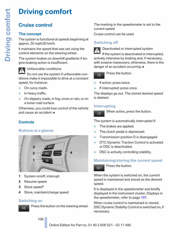
Driving comfortCruise controlThe conceptThe system is functional at speeds beginning atapprox. 20 mph/30 km/h.It maintains the speed that was set using thecontrol elements on the steering wheel.The system brakes on downhill gradients if en‐gine braking action is insufficient.
Unfavorable conditionsDo not use the system if unfavorable con‐
ditions make it impossible to drive at a constantspeed, for instance:▷ On curvy roads.▷ In heavy traffic.▷ On slippery roads, in fog, snow or rain, or on
a loose road surface.Otherwise, you could lose control of the vehicleand cause an accident.◀
Controls
Buttons at a glance
1 System on/off, interrupt2 Resume speed3 Store speed*4 Store, maintain/change speed
Switching onPress the button on the steering wheel.
The marking in the speedometer is set to thecurrent speed.Cruise control can be used.
Switching offDeactivated or interrupted systemIf the system is deactivated or interrupted,
actively intervene by braking and, if necessary,with evasive maneuvers; otherwise, there is thedanger of an accident occurring.◀
Press the button.
▷ If active: press twice.▷ If interrupted: press once.The displays go out. The stored desired speedis deleted.
InterruptingWhen active, press the button.
The system is automatically interrupted if:▷ The brakes are applied.▷ The clutch pedal is depressed.▷ Transmission position D is disengaged.▷ DTC Dynamic Traction Control is activated
or DSC is deactivated.▷ DSC is actively controlling stability.
Maintaining/storing the current speedPress the button.
When the system is switched on, the currentspeed is maintained and stored as the desiredspeed.It is displayed in the speedometer and brieflydisplayed in the instrument cluster, Displays inthe speedometer, refer to page 107.When cruise control is maintained or stored,DSC Dynamic Stability Control is switched on, ifnecessary.
Seite 106
106Online Edition for Part no. 01 40 2 606 521 - 03 11 490
Drivi
ng co
mfo
rt

Change, maintain speedThe rocker switch can be pressed while inter‐rupted to maintain and store the current speed.
Adapting the desired speedAdapt the desired speed to the road con‐
ditions and be ready to brake at all times; other‐wise, there is the danger of an accident occur‐ring.◀
Press the rocker switch up or down repeatedlyuntil the desired speed is set.If active, the displayed speed is stored and thevehicle reaches the stored speed if the road isclear.▷ Each time the rocker switch is pressed to the
point of resistance, the desired speed in‐creases or decreases by approx. 1 mph/1 km/h.
▷ Each time the rocker switch is pressed pastthe point of resistance, the desired speedincreases or decreases by a maximum of5 mph/10 km/h.
▷ Pressing the rocker switch to the resistancepoint and holding it accelerates or deceler‐ates the vehicle without requiring pressureon the accelerator. After the rocker switch isreleased, the vehicle maintains its finalspeed. Pressing the switch beyond the re‐sistance point causes the vehicle to accel‐erate more rapidly.
Resuming the desired speedPress the button.
The stored speed is reached and maintained.
Displays in the instrument cluster
1 Display of desired speed2 Indicator lamp3 Brief status display
Desired speedDisplay in the speedometer:
▷ The marking lights up ingreen: the system is active.
▷ The marking lights up in or‐ange: the system has beeninterrupted.
▷ The marking does not light up: the system isswitched off.
Brief status displayBrief display in the speedometer:
Selected desired speed
If --- appears briefly, conditions may not be ad‐equate to operate the system.
PDC Park Distance Control*The conceptIn addition to the PDC Park Distance Control, thebackup camera*, refer to page 110, can beswitched on.PDC supports you when parking. Objects thatyou are approaching slowly in front of or behindyour vehicle are indicated with:▷ Signal tones.▷ Visual display.
Seite 107
107Online Edition for Part no. 01 40 2 606 521 - 03 11 490
Re
fere
nce
Mob
ility
Com
mun
icat
ion
Ente
rtain
men
tNa
vigat
ion
Drivi
ng ti
psCo
ntro
lsAt
a gl
ance
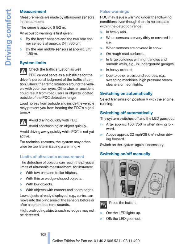
MeasurementMeasurements are made by ultrasound sensorsin the bumpers.The range is approx. 6 ft/2 m.An acoustic warning is first given:▷ By the front* sensors and the two rear cor‐
ner sensors at approx. 24 in/60 cm.▷ By the rear middle sensors at approx. 5 ft/
1.50 m.
System limitsCheck the traffic situation as wellPDC cannot serve as a substitute for the
driver's personal judgment of the traffic situa‐tion. Check the traffic situation around the vehi‐cle with your own eyes. Otherwise, an accidentcould result from road users or objects locatedoutside of the PDC detection range.Loud noises from outside and inside the vehiclemay prevent you from hearing the PDC's signaltone.◀
Avoid driving quickly with PDCAvoid approaching an object quickly.
Avoid driving away quickly while PDC is not yetactive.For technical reasons, the system may other‐wise be too late in issuing a warning.◀
Limits of ultrasonic measurementThe detection of objects can reach the physicallimits of ultrasonic measurement, for instance:▷ With tow bars and trailer hitches.▷ With thin or wedge-shaped objects.▷ With low objects.▷ With objects with corners and sharp edges.Low objects already displayed, e.g., curbs, canmove into the blind area of the sensors before orafter a continuous tone sounds.High, protruding objects such as ledges may notbe detected.
False warningsPDC may issue a warning under the followingconditions even though there is no obstaclewithin the detection range:▷ In heavy rain.▷ When sensors are very dirty or covered in
ice.▷ When sensors are covered in snow.▷ On rough road surfaces.▷ In large buildings with right angles and
smooth walls, e.g., in underground garages.▷ In heavy exhaust.▷ Due to other ultrasound sources, e.g.,
sweeping machines, high pressure steamcleaners or neon lights.
Switching on automaticallySelect transmission position R with the enginerunning.
Switching off automaticallyThe system switches off and the LED goes out:▷ After approx. 160 ft/50 m when driving for‐
ward.▷ Above approx. 22 mph/36 km/h when driv‐
ing forward.Switch on the system again if necessary.
Switching on/off manually
Press the button.
▷ On: the LED lights up.▷ Off: the LED goes out.
Seite 108
108Online Edition for Part no. 01 40 2 606 521 - 03 11 490
Drivi
ng co
mfo
rt

Signal tonesWhen approaching an object, an intermittenttone is sounded that indicates the position of theobject. For example, if an object is detected tothe left rear of the vehicle, a signal tone soundsfrom the left rear speaker.The shorter the distance to the object becomes,the shorter the intervals.If the distance to a detected object is less thanapprox. 12 in/30 cm, a continuous tone issounded.If objects are located both in front of and behindthe vehicle, an alternating continuous signal issounded.The intermittent tone is interrupted after approx.3 seconds:▷ If the vehicle stops in front of an object that
is detected by only one of the corner sen‐sors.
▷ If moving parallel to a wall.The signal tone is switched off:▷ When the vehicle moves away from an ob‐
ject by more than approx. 4 in/10 cm.▷ When transmission position P is engaged.
VolumeYou can set the volume of the PDC signal tone,refer to page 165.The setting is stored for the remote control cur‐rently in use.
Visual warningThe approach of the vehicle to an object can beshown on the Control Display. Objects that arefarther away are displayed on the Control Dis‐play before a signal tone sounds.A display appears as soon as Park DistanceControl (PDC) is activated.If the backup camera image was selected last, itagain appears on the display. To switch to PDC:
1. "Rear view camera" Select the symbolon the Control Display.
2. Press the controller.
The setting is stored for the remote control cur‐rently in use.
Zoom view*On the left part of the display screen, the vehicleis shown enlarged.
▷ Forward gear or transmission position D en‐gaged: front area of the vehicle.
▷ Reverse gear or transmission position R en‐gaged: rear area of the vehicle.
Display on the Control Display
Switching on the backup camera via theiDriveWith PDC activated:
"Rear view camera"The backup camera image is displayed. The set‐ting is stored for the remote control currently inuse.
MalfunctionA Check Control message is displayed.
On the Control Display, the areas in front of andbehind the vehicle are shaded. PDC has failed.Have the system checked.
To ensure full operability:
Seite 109
109Online Edition for Part no. 01 40 2 606 521 - 03 11 490
Re
fere
nce
Mob
ility
Com
mun
icat
ion
Ente
rtain
men
tNa
vigat
ion
Drivi
ng ti
psCo
ntro
lsAt
a gl
ance
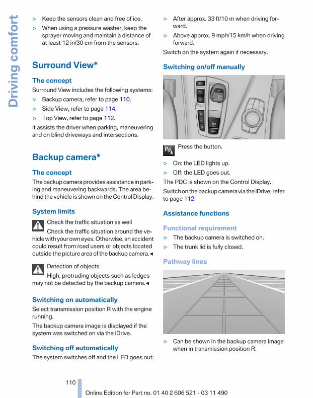
▷ Keep the sensors clean and free of ice.▷ When using a pressure washer, keep the
sprayer moving and maintain a distance ofat least 12 in/30 cm from the sensors.
Surround View*The conceptSurround View includes the following systems:▷ Backup camera, refer to page 110.▷ Side View, refer to page 114.▷ Top View, refer to page 112.It assists the driver when parking, maneuveringand on blind driveways and intersections.
Backup camera*The conceptThe backup camera provides assistance in park‐ing and maneuvering backwards. The area be‐hind the vehicle is shown on the Control Display.
System limitsCheck the traffic situation as wellCheck the traffic situation around the ve‐
hicle with your own eyes. Otherwise, an accidentcould result from road users or objects locatedoutside the picture area of the backup camera.◀
Detection of objectsHigh, protruding objects such as ledges
may not be detected by the backup camera.◀
Switching on automaticallySelect transmission position R with the enginerunning.The backup camera image is displayed if thesystem was switched on via the iDrive.
Switching off automaticallyThe system switches off and the LED goes out:
▷ After approx. 33 ft/10 m when driving for‐ward.
▷ Above approx. 9 mph/15 km/h when drivingforward.
Switch on the system again if necessary.
Switching on/off manually
Press the button.
▷ On: the LED lights up.▷ Off: the LED goes out.The PDC is shown on the Control Display.Switch on the backup camera via the iDrive, referto page 112.
Assistance functions
Functional requirement▷ The backup camera is switched on.▷ The trunk lid is fully closed.
Pathway lines
▷ Can be shown in the backup camera imagewhen in transmission position R.
Seite 110
110Online Edition for Part no. 01 40 2 606 521 - 03 11 490
Drivi
ng co
mfo
rt

▷ Help you to estimate the space requiredwhen parking and maneuvering on levelroads.
▷ Are dependent on the current steering angleand are continuously adjusted to the steer‐ing wheel movements.
Show the parking aid lines, refer to page 111.
Turning circle lines
▷ Can be shown in the backup camera image.▷ Show the course of the smallest possible
turning circle on a level road.▷ Only one turning circle line is displayed
when the steering wheel is turned.Show the parking aid lines, refer to page 111.
Parking using pathway and turningcircle lines1. Position the vehicle so that the turning circle
lines lead to within the limits of the parkingspace.
2. Turn the steering wheel to the point wherethe pathway line covers the correspondingturning circle line.
Obstacle marking
▷ Spatially-shaped markings can be shown inthe backup camera image.
Their colored steps match the markings of thePDC. This simplifies estimation of the distanceto the object shown.
Activating the assistance functionsMore than one assistance function can be activeat the same time.
Showing the parking aid lines "Parking aid lines"
Pathway and turning circle lines are displayed.
Showing the obstacle marking "Obstacle marking"
Spatially-shaped markings are displayed.
Seite 111
111Online Edition for Part no. 01 40 2 606 521 - 03 11 490
Re
fere
nce
Mob
ility
Com
mun
icat
ion
Ente
rtain
men
tNa
vigat
ion
Drivi
ng ti
psCo
ntro
lsAt
a gl
ance

Display on the Control Display
Switching on the backup camera viaiDriveWith PDC activated:
"Rear view camera"The backup camera image is displayed. The set‐ting is stored for the remote control currently inuse.
BrightnessWith the backup camera switched on:
1. Select the symbol.2. Turn the controller until the desired setting
is reached and press the controller.
ContrastWith the backup camera switched on:
1. Select the symbol.2. Turn the controller until the desired setting
is reached and press the controller.
Camera
The camera lens is located under the BMW em‐blem of the trunk lid. The image quality may beimpaired by dirt.Clean the lens, refer to page 257.
Top View*The conceptTop View assists you in parking and maneuver‐ing. The area around the doors and the road area
around the vehicle are shown on the ControlDisplay for this purpose.
Capturing the imageThe image is captured by two camerasintegrated in the exterior mirrors and by thebackup camera.The range equals:▷ approx. 7 ft/2 m to the side.▷ approx. 7 ft/2 m to the rear.In this way, obstacles up to the height of the ex‐terior mirrors are detected early.
System limitsTop View cannot be used in the following situa‐tions:▷ With a door open.▷ With the trunk lid open.▷ With an exterior mirror folded in.▷ In poor light.A Check Control message is displayed in someof these situations.
Check the traffic situation as wellCheck the traffic situation around the ve‐
hicle with your own eyes. Otherwise, an accidentcould result from road users or objects locatedoutside the picture area of the cameras.◀
Switching on automaticallySelect transmission position R with the enginerunning.The Top View and PDC images are displayed ifthe system is switched on via iDrive.
Switching off automaticallyThe system switches off and the LED goes out:▷ After approx. 160 ft/50 m when driving for‐
ward.▷ Above approx. 22 mph/36 km/h when driv‐
ing forward.Switch on the system again if necessary.
Seite 112
112Online Edition for Part no. 01 40 2 606 521 - 03 11 490
Drivi
ng co
mfo
rt

Switching on/off manually
Press the button.
▷ On: the LED lights up.▷ Off: the LED goes out.If Top View is displayed, switch on the backupcamera via the iDrive, refer to page 113.
Visual warningThe approach of the vehicle to an object can beshown on the Control Display.When the distance to an object is small, a red baris shown in front of the vehicle, as it is in the PDCdisplay.
The display appears as soon as Top View is ac‐tivated.
If the backup camera image was selected last, itagain appears on the display. To switch to TopView:
"Rear view camera" Select the symbol onthe Control Display.The setting is stored for the remote control cur‐rently in use.
Display on the Control Display
Switching on the backup camera viaiDriveWith Top View switched on:
"Rear view camera"The backup camera image is displayed. The set‐ting is stored for the remote control currently inuse.
BrightnessWith Top View switched on:
1. "Brightness"2. Turn the controller until the desired setting
is reached and press the controller.
ContrastWith Top View switched on:
1. "Contrast"2. Turn the controller until the desired setting
is reached and press the controller.
Displaying the turning circle andpathway lines▷ The static, red turning circle line shows the
space needed to the side of the vehiclewhen the steering wheel is turned all theway.
▷ The variable, green pathway line assists youin assessing the amount of space actuallyneeded to the side of the vehicle.The pathway line is dependent on the cur‐rent steering angle and is continuously ad‐justed with the steering wheel movement.
"Parking aid lines"Turning circle and pathway lines are displayed.
Seite 113
113Online Edition for Part no. 01 40 2 606 521 - 03 11 490
Re
fere
nce
Mob
ility
Com
mun
icat
ion
Ente
rtain
men
tNa
vigat
ion
Drivi
ng ti
psCo
ntro
lsAt
a gl
ance

Cameras
The objectives of the Top View cameras are lo‐cated at the bottom of the exterior mirror hous‐ings. The image quality may be impaired by dirt.Clean the lens, refer to page 257.
Side View*The conceptSide View provides an early look at cross trafficat blind driveways and intersections. Road usersconcealed by obstacles to the left and right ofthe vehicle can only be detected relatively latefrom the driver's seat. To improve visibility, twocameras in the front of the vehicle record thetraffic situation on each side.
System limitsThe maximum recording range of the camera is330 ft/100 m.
DisplayThe images from both cameras are shown si‐multaneously on the Control Display.
Check the traffic situation as wellCheck the traffic situation around the ve‐
hicle on blind driveways and intersections withyour own eyes. Otherwise, an accident could re‐sult from road users or objects located outsidethe picture area of the Side View cameras.◀
Switching off automaticallySystem switches off: above approx. 9 mph/15 km/h.Switch on the system again if necessary.
Switching on/off manually
Press the button.
Display on the Control DisplayThe traffic area to the left and right is displayedon the Control Display.
Guidelines at the bottom of the image show theposition of the front of the vehicle.
BrightnessWith the Side View switched on:
1. "Brightness"2. Turn the controller until the desired setting
is reached and press the controller.
ContrastWith the Side View switched on:
1. "Contrast"2. Turn the controller until the desired setting
is reached and press the controller.
Seite 114
114Online Edition for Part no. 01 40 2 606 521 - 03 11 490
Drivi
ng co
mfo
rt

Cameras
The two camera lenses are located on the sidesof the bumper.The image quality may be impaired by dirt.Clean the lens, refer to page 257.
Parking assistant*The concept
This system assists the driver in parking parallelto the road.Ultrasound sensors measure parking spaces onboth sides of the vehicle.The parking assistant calculates the best pos‐sible parking line and takes control of steeringduring the parking procedure.When parking, also take note of the visual andacoustic information issued by the PDC and theparking assistant and accelerate or brake ac‐cordingly.A component of the parking assistant is the PDCPark Distance Control*, refer to page 107.
Personal responsibilityThe parking assistant does not relieve the
driver of responsibility for the vehicle during theparking procedure.Watch the parking space and parking procedureclosely and intervene if necessary; otherwise,there is the danger of an accident.◀
Requirements
For measuring parking spaces▷ Maximum speed while driving forward ap‐
prox. 22 mph/35 km/h.▷ Maximum distance to row of parked vehi‐
cles: 5 ft/1.5 m.
Suitable parking space▷ Gap between two objects with a minimum
length of approx. 5 ft/1.5 m.▷ Minimum length: own vehicle length plus
approx. 4 ft/1.2 m.▷ Minimum depth: approx. 5 ft/1.5 m.
For parking procedureClosed doors.
Switching on
Using the button
Press the button.The LED lights up.
The parking assistant is activated automati‐cally.The current status of the parking space searchis indicated on the Control Display.
Seite 115
115Online Edition for Part no. 01 40 2 606 521 - 03 11 490
Re
fere
nce
Mob
ility
Com
mun
icat
ion
Ente
rtain
men
tNa
vigat
ion
Drivi
ng ti
psCo
ntro
lsAt
a gl
ance

By engaging reverseEngage transmission position R.The current status of the parking space searchis indicated on the Control Display.Activate: "Parking Assistant" Select thesymbol in the Control Display.
Display on the Control Display
System status
Symbol Meaning
Gray: the system is not available.White: the system is available but notactivated.
The system is activated.
Gray: the system is not activated.Parking space search.Blue: the system is activated. Asuitable parking space wasfound.
The parking procedure is active.Steering control has been seized.
Status of the parking space search
▷ Gray, arrow 1: parking space search.▷ Blue, arrow 2: parking space is suitable.
The vehicle is parked in the parking space ifthe parking procedure is active.
▷ No display: no parking space search.
Parking using the parking assistantPersonal responsibilityThe parking assistant does not relieve the
driver of responsibility for the vehicle during theparking procedure.Watch the parking space and parking procedureclosely and intervene if necessary; otherwise,there is the danger of an accident.◀
Check the traffic situation as wellLoud sounds outside and within the vehi‐
cle can drown out the signal tones of the parkingassistant and PDC.Check the traffic situation around the vehiclewith your own eyes; otherwise, there is the dan‐ger of an accident.◀
1. Switch on the parking assistant and activateit if necessary.The status of the parking space search is in‐dicated on the Control Display.
2. Follow the instructions on the Control Dis‐play.The end of the parking procedure is indi‐cated on the Control Display.
3. Adjust the parking position yourself if nec‐essary.
Seite 116
116Online Edition for Part no. 01 40 2 606 521 - 03 11 490
Drivi
ng co
mfo
rt

Notes▷ The parking assistant takes control of steer‐
ing for as long as the symbol for active park‐ing appears on the display.
▷ The system maneuvers the vehicle to posi‐tion it properly in smaller parking spaces, forexample.
▷ To achieve the best possible parking posi‐tion, wait for the automatic steering wheelmovement after the gear change when thevehicle is stationary.
▷ When parking in parking spaces on the driv‐er's side, the corresponding turn signal mustbe set.
Interrupting manuallyThe parking assistant can be interrupted at anytime by:▷ Grasping the steering wheel and steering
yourself.▷ "Deactivate Parking Assistant" Select
the symbol on the Control Display.
Interrupting automaticallyThe procedure is interrupted automatically:▷ If the vehicle speed exceeds approx. 6 mph/
10 km/h.▷ On snow-covered or slippery road surfaces
if necessary.▷ If doors are open.A Check Control message is displayed.
ContinuingAn interrupted parking procedure can be con‐tinued if necessary.Follow the instructions on the Control Display todo this.
Switching offThe system can be deactivated as follows:▷ Press the button.
▷ Switch off the ignition.
MalfunctionA Check Control message is displayed.The parking assistant failed. Have the systemchecked.
System limitsChanges to the parking spaceChanges to the parking space after it was
measured are not taken into account by the sys‐tem.Therefore, always be alert and ready to inter‐vene; otherwise, there is the danger of an acci‐dent occurring.◀
Transporting loadsLoads that extend beyond the perimeter
of the vehicle are not taken into account by thesystem during the parking procedure.Therefore, always be alert and ready to inter‐vene; otherwise, there is the danger of an acci‐dent occurring.◀
CurbsThe parking assistant may steer the vehi‐
cle over or onto curbs.Therefore, always be alert and ready to inter‐vene; otherwise, the wheels, tires, or the vehiclemay become damaged.◀
No parking assistanceThe parking assistant does not provide assis‐tance in parking.▷ In tight curves.
Functional limitationsThe system may not be fully functional in thefollowing situations:▷ When sensors are dirty or iced over.▷ In heavy fog, rain or snowfall.▷ On bumpy road surfaces such as gravel
roads.▷ When leaves or snow has collected in the
parking space.
Seite 117
117Online Edition for Part no. 01 40 2 606 521 - 03 11 490
Re
fere
nce
Mob
ility
Com
mun
icat
ion
Ente
rtain
men
tNa
vigat
ion
Drivi
ng ti
psCo
ntro
lsAt
a gl
ance

Limits of ultrasonic measurementThe detection of objects can reach the physicallimits of ultrasonic measurement, for instance:▷ With tow bars and trailer hitches.▷ With thin or wedge-shaped objects.▷ With elevated, protruding objects such as
ledges or cargo.▷ With objects with corners and sharp edges.▷ With objects with a fine surface structure,
such as fences.The parking assistant may identify parkingspaces that are not suitable for parking.
Ultrasound sensors
The ultrasounds sensors used to measure park‐ing spaces are located in the side turn signals.To ensure full operability:▷ Keep the sensors clean and free of ice.▷ When using a pressure washer, keep the
sprayer moving and maintain a distance ofat least 12 in/30 cm from the sensors.
Night Vision with pedestriandetection*The conceptNight Vision with pedestrian detection is a nightvision system.An infrared camera records the area in front ofthe vehicle and displays the image on the Con‐trol Display.The picture is a heat image. The system has anintegrated pedestrian detection function thatdetects pedestrians and cyclists. Warm objects
that are similar in shape to human beings aredetected by the system.
Personal responsibilityNight Vision cannot replace the driver's
personal judgment of the visibility conditionsand the traffic situation. The view ahead and theactual visibility conditions must always be thebasis on which the vehicle speed is adjusted;otherwise, there is a risk to road safety.◀
Heat image
The image shows the heat radiated by objectsin the field of view of the camera.Warm objects have a light appearance and coldobjects, a dark appearance.The ability to detect an object depends on thetemperature difference between the object andthe background and on the level of heat radiationemitted by the object. Objects that are similar intemperature to the environment or that radiatevery little heat are difficult to detect.
For safety reasons, when driving at speedsabove approx. 3 mph/5 km/h and in low ambientlight, the image is only displayed when the lowbeams are switched on.A still image is displayed at regular intervals fora fraction of a second.
Seite 118
118Online Edition for Part no. 01 40 2 606 521 - 03 11 490
Drivi
ng co
mfo
rt

Pedestrian detection
The pedestrian detection and warning systemonly operates in darkness and only when a heatimage is displayed.Warm objects that are similar in shape to humanbeings are detected by the system.People detected by the system are displayedwith a slight yellow hue.
Under good ambient conditions, the pedestriandetection system operates within a range of ap‐prox. 50 ft/15 m to approx. 330 ft/100 m.
Environmental influences can limit the availabil‐ity of pedestrian detection.If pedestrian detection is not available, a symbolis displayed in the heat image.This symbol disappears when the function be‐comes available again.
Warning of people in danger
If the system detects a person in the definedarea in front of the vehicle and if there is the dan‐ger of a collision with this person, a warningsymbol appears in the Control Display andHead-up Display*.Although both the shape and the heat radiationare analyzed, false warnings cannot be ruled out.
Warning area in front of the vehicle
The warning area in front of the vehicle is dividedinto two areas.▷ Central area 1 directly in front of the vehicle.▷ Expanded area 2 to the right and left.The entire area moves along with the vehicle inthe direction of the steering angle and changeswith the vehicle speed. As the vehicle speed in‐creases, the area becomes longer and wider, forexample.
SymbolsThis symbol is displayed when a personis detected in the central area, arrow 1,immediately in front of the vehicle.
This symbol is displayed when a persondetected in the extended area, arrow 2,
Seite 119
119Online Edition for Part no. 01 40 2 606 521 - 03 11 490
Re
fere
nce
Mob
ility
Com
mun
icat
ion
Ente
rtain
men
tNa
vigat
ion
Drivi
ng ti
psCo
ntro
lsAt
a gl
ance

is moving from the right or left to the central area.
Display in the Head-up Display*The warning is simultaneously dis‐played in the Head-up Display and in theControl Display. The displayed symbol
can vary with the people detected. For peoplelocated in the central area, the distance to theperson is indicated by the size of the symbol.
System limits
Basic limitsSystem operation is limited in situations such asthe following:▷ On steep hills, in steep depressions or in
tight curves.▷ When the camera is dirty or the protective
glass is damaged.▷ In heavy fog, rain or snowfall.▷ At very high external temperatures.
Limits of pedestrian detectionAnimals are not detected by the pedestrian de‐tection function, even if they are clearly visible inthe image.Limited pedestrian detection:▷ When people are fully or partially covered,
especially when their heads are covered.▷ When people are not in an upright position,
e.g., when lying down.▷ Cyclists on unconventional bicycles (e.g.,
recumbent bicycles).▷ After physical damage to the system, e.g.,
after an accident.
Activation/deactivation
Press the button.
Display
Settings via iDriveWith Night Vision switched on:
1. Activate Night Vision with pedestrian detec‐tion.
2. Press the controller.3. Open the desired menu item.
▷ "Brightness"▷ "Contrast"▷ "Pedestrian detection"
The settings are stored for the remote controlcurrently in use.
Camera
Rain, dirt, snow, or ice can impair camera oper‐ation.The camera is automatically heated when theexternal temperatures are low.The camera is automatically cleaned togetherwith the headlamps.
Seite 120
120Online Edition for Part no. 01 40 2 606 521 - 03 11 490
Drivi
ng co
mfo
rt

Clean the lens, refer to page 257.
Head-up Display*The concept
This system projects important information intothe driver's field of vision, e.g., the speed.In this way, the driver can get information with‐out averting his or her eyes from the road.
Display visibilityThe visibility of the displays in the Head-up Dis‐play is influenced by:▷ Certain sitting positions.▷ Objects on the cover of the Head-up Dis‐
play.▷ Sunglasses with certain polarization filters.▷ Wet roads.▷ Unfavorable light conditions.If the image is distorted, check the basic set‐tings.
Switching on/off
Press the button.
Display
1 Lane departure warning*2 Active Cruise Control*3 Desired speed4 Navigation system*5 SpeedThe collision warning*, Night Vision* pedestrianwarning, or Check Control messages are dis‐played briefly if needed.
Selecting displays in the Head-upDisplay1. "Settings"2. "Head-up display"3. "Displayed information"4. Select the desired displays in the Head-up
Display.The settings are stored for the remote controlcurrently in use.
Setting the brightnessThe brightness is automatically adjusted to theambient light.The basic setting can be adjusted manually.
1. "Settings"2. "Head-up display"3. "Brightness"4. Turn the controller.
The brightness is adjusted.When the low beams are switched on, thebrightness of the Head-up Display can be addi‐tionally influenced using the instrument lighting,refer to page 87.
Seite 121
121Online Edition for Part no. 01 40 2 606 521 - 03 11 490
Re
fere
nce
Mob
ility
Com
mun
icat
ion
Ente
rtain
men
tNa
vigat
ion
Drivi
ng ti
psCo
ntro
lsAt
a gl
ance

The setting is stored for the remote control cur‐rently in use.
Adjusting the height1. "Settings"2. "Head-up display"3. "Height"4. Turn the controller.
The height is adjusted.The setting is stored for the remote control cur‐rently in use.
Special windshieldThe windshield is part of the system.The shape of the windshield makes it possibleto display a precise image.A film in the windshield prevents double imagesfrom being displayed.Therefore, have the special windshield replacedby a service center only.
Seite 122
122Online Edition for Part no. 01 40 2 606 521 - 03 11 490
Drivi
ng co
mfo
rt
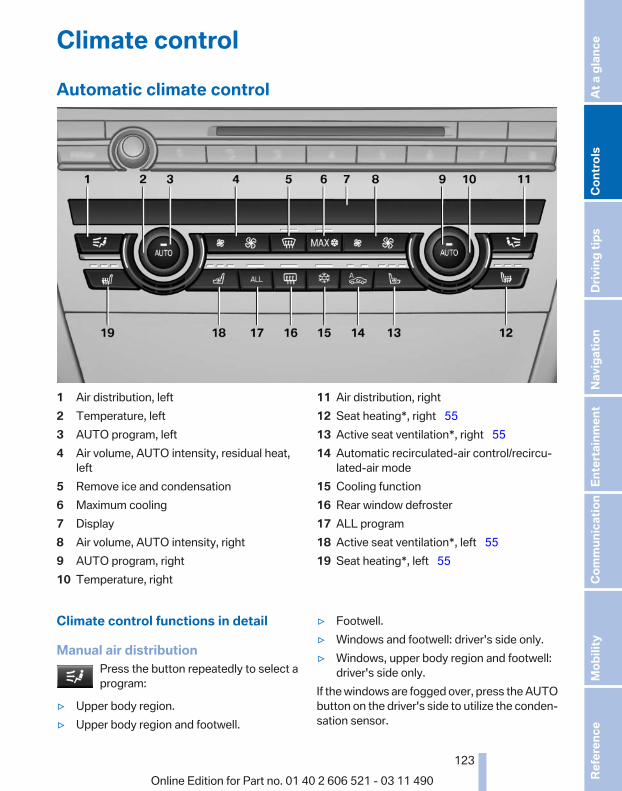
Climate controlAutomatic climate control
1 Air distribution, left2 Temperature, left3 AUTO program, left4 Air volume, AUTO intensity, residual heat,
left5 Remove ice and condensation6 Maximum cooling7 Display8 Air volume, AUTO intensity, right9 AUTO program, right10 Temperature, right
11 Air distribution, right12 Seat heating*, right 5513 Active seat ventilation*, right 5514 Automatic recirculated-air control/recircu‐
lated-air mode15 Cooling function16 Rear window defroster17 ALL program18 Active seat ventilation*, left 5519 Seat heating*, left 55
Climate control functions in detail
Manual air distributionPress the button repeatedly to select aprogram:
▷ Upper body region.▷ Upper body region and footwell.
▷ Footwell.▷ Windows and footwell: driver's side only.▷ Windows, upper body region and footwell:
driver's side only.If the windows are fogged over, press the AUTObutton on the driver's side to utilize the conden‐sation sensor.
Seite 123
123Online Edition for Part no. 01 40 2 606 521 - 03 11 490
Re
fere
nce
Mob
ility
Com
mun
icat
ion
Ente
rtain
men
tNa
vigat
ion
Drivi
ng ti
psCo
ntro
lsAt
a gl
ance
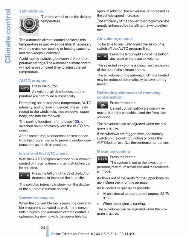
TemperatureTurn the wheel to set the desiredtemperature.
The automatic climate control achieves thistemperature as quickly as possible, if necessarywith the maximum cooling or heating capacity,and then keeps it constant.Avoid rapidly switching between different tem‐perature settings. The automatic climate controlwill not have sufficient time to adjust the settemperature.
AUTO programPress the button.Air volume, air distribution, and tem‐
perature are controlled automatically.
Depending on the selected temperature, AUTOintensity, and outside influences, the air is di‐rected to the windshield, side windows, upperbody, and into the footwell.The cooling function, refer to page 125, isswitched on automatically with the AUTO pro‐gram.At the same time, a condensation sensor con‐trols the program so as to prevent window con‐densation as much as possible.
Intensity of the AUTO programWith the AUTO program switched on, automaticcontrol of the air volume and air distribution canbe adjusted.
Press the left or right side of the button:decrease or increase the intensity.
The selected intensity is shown on the displayof the automatic climate control.
Convertible programWhen the convertible top is open, the converti‐ble program is activated as well. In the conver‐tible program, the automatic climate control isoptimized for driving with the convertible top
open. In addition, the air volume is increased asthe vehicle speed increases.The efficiency of the convertible program can begreatly enhanced by installing the wind deflec‐tor*.
Air volume, manualTo be able to manually adjust the air volume,switch off the AUTO program first.
Press the left or right side of the button:decrease or increase air volume.
The selected air volume is shown on the displayof the automatic climate control.The air volume of the automatic climate controlmay be reduced automatically to save batterypower.
Defrosting windows and removingcondensation
Press the button.Ice and condensation are quickly re‐
moved from the windshield and the front sidewindows.
The air volume can be adjusted when the pro‐gram is active.If the windows are fogged over, additionallyswitch on the cooling function or press theAUTO button to utilize the condensation sensor.
Maximum coolingPress the button.The system is set to the lowest tem‐
perature, maximum air volume and recirculated-air mode.
Air flows out of the vents for the upper body re‐gion. Open them for this purpose.Air is cooled as quickly as possible:▷ At an external temperature of approx. 32 ℉/
0 ℃.▷ When the engine is running.The air volume can be adjusted when the pro‐gram is active.
Seite 124
124Online Edition for Part no. 01 40 2 606 521 - 03 11 490
Clim
ate
cont
rol

Automatic recirculated-air control/recirculated-air modeYou can respond to unpleasant odors or pollu‐tants in the immediate environment by tempo‐rarily suspending the supply of outside air. Thesystem then recirculates the air currently withinthe vehicle.
Press the button repeatedly to selectan operating mode:
▷ LEDs off: outside air flows in continuously.▷ Left LED on, automatic recirculated-air con‐
trol: a sensor detects pollutants in the out‐side air and controls the shut-off automati‐cally.
▷ Right LED on, recirculated-air mode: thesupply of outside air into the vehicle is per‐manently blocked.
If the windows are fogged over, switch off therecirculated-air mode and press the AUTO but‐ton on the driver's side to utilize the condensa‐tion sensor. Make sure that air can flow onto thewindshield.
Continuous recirculated-air modeThe recirculated-air mode should not be
used for an extended period of time, as the airquality inside the vehicle deteriorates steadily.◀
Cooling functionThe passenger compartment can only becooled with the engine running.
Press the button.The air is cooled and dehumidified and
– depending on the temperature setting –warmed again.
Depending on the weather, the windshield mayfog up briefly when the engine is started.The cooling function is switched on automati‐cally with the AUTO program.When using the automatic climate control, con‐densation water, refer to page 140, developsthat exits underneath the vehicle.
Rear window defrosterPress the button.The rear window defroster switches off
automatically after a certain period of time.The rear window defroster is only active whenthe rear window is closed.
ALL programPress the button.Current settings on the driver's side for
the temperature, air volume, air distribution, andAUTO program are transferred to the front pas‐senger side.The program is switched off if the settings onthe front passenger side are changed.
Residual heatThe heat stored in the engine is used to heat theinterior.
Functional requirement▷ Up to 20 minutes after the engine has been
switched off.▷ Warm engine.▷ The battery is sufficiently charged.▷ External temperature below 77 ℉/25 ℃.
Switching on1. Switch off the ignition.
2. Press the right side of the button onthe driver's side.
is shown on the display of the automatic cli‐mate control.The interior temperature, air volume and air dis‐tribution can be adjusted with the ignitionswitched on.
Switching offAt the lowest fan speed, press the left side of thebutton on the driver's side.
on the display of the automatic climate controlgoes out.
Seite 125
125Online Edition for Part no. 01 40 2 606 521 - 03 11 490
Re
fere
nce
Mob
ility
Com
mun
icat
ion
Ente
rtain
men
tNa
vigat
ion
Drivi
ng ti
psCo
ntro
lsAt
a gl
ance

Switching the system on/off
Switching off▷ Complete system:
At the lowest fan speed, press theleft side of the button on the driver's
side.▷ On the front passenger side:
At the lowest fan speed, press theleft side of the button on the front
passenger side.
Switching onPress any button.
Microfilter/activated-charcoal filterThe microfilter removes dust and pollen fromthe incoming air.The activated-charcoal filter removes gaseouspollutants from the outside air that enters thevehicle.This combined filter should be replaced duringscheduled maintenance of your vehicle., refer topage 241
Ventilation
▷ Thumbwheel to vary the temperature, ar‐row 1.Toward blue: colder.Toward red: warmer.
▷ Lever for changing the air flow direction, ar‐row 2.
▷ Thumbwheels for opening and closing thevents continuously, arrows 3.
Adjusting the ventilation▷ Ventilation for cooling:
Adjust the vent to direct the air in your di‐rection, e.g., if the vehicle interior is hot fromthe sun.
▷ Draft-free ventilation:Adjust the vent to let the air flow past you.
Parked-car ventilationThe conceptThe parked-car ventilation ventilates the vehicleinterior and lowers its temperature, if necessary.The system can be switched on and off directlyor by using two preset switch-on times. It re‐mains switched on for 30 minutes.They can be operated via iDrive.
Parked-car ventilationUsing the preset switch-on time or when oper‐ated directly: any external temperature.Open the vents to allow air to flow out.
Switching on/off directly1. "Settings"2. "Climate"3. "Activate parked-car vent."
The symbol on the automatic climate controlflashes if the system is switched on.The system continues to run for some time afterbeing switched off.
Preselecting the switch-on time1. "Settings"2. "Climate"3. "Timer 1:" or "Timer 2:"4. Set the desired time.
Activating the switch-on time1. "Settings"2. "Climate"3. "Activate Timer 1" or "Activate Timer 2"
Seite 126
126Online Edition for Part no. 01 40 2 606 521 - 03 11 490
Clim
ate
cont
rol

The symbol on the automatic climate controllights up when the switch-on time is activated.
The symbol on the automatic climate controlflashes when the system has been switched on.The system will only be switched on within thenext 24 hours. After that, it needs to reactivated.
Seite 127
127Online Edition for Part no. 01 40 2 606 521 - 03 11 490
Re
fere
nce
Mob
ility
Com
mun
icat
ion
Ente
rtain
men
tNa
vigat
ion
Drivi
ng ti
psCo
ntro
lsAt
a gl
ance

Interior equipmentIntegrated universal remotecontrol*The conceptThis system can replace up to three differenthand-held transmitters for various types of re‐mote-controlled equipment, such as garagedoors or lighting systems.The hand-held transmitter signal can be pro‐grammed on one of the three memory buttons.The corresponding device can then be operatedusing the programmed memory button.The LED indicates that a signal is being trans‐mitted.When selling the vehicle, delete the stored pro‐grams for security reasons.
During programmingDuring programming and before activat‐
ing a device using the universal remote control,ensure that there are no people, animals, or ob‐jects in the range of movement of the remote-controlled device; otherwise, there is a risk ofinjury or damage.Also follow the safety instructions of the hand-held transmitter.◀
CompatibilityIf this symbol is printed on the packagingor in the instructions of the hand-heldtransmitter, the remote-controlled de‐
vice is generally compatible with the universalremote control.If you have any questions, please contact:▷ Your service center.▷ www.homelink.com on the Internet.
Programming
▷ LED, arrow 1.▷ Memory buttons, arrow 2.
Fixed-code hand-held transmitters1. Switch on the ignition.2. Initial setup:
Press both outer buttons 1 and 3 for approx.20 seconds until the LED flashes.All programs of the three memory buttons,arrow 2, are cleared.
3. Hold the hand-held transmitter a distance ofapprox. 2 to 8 in/5 to 20 cm from the memorybuttons.
4. Simultaneously press the transmit button ofthe hand-held transmitter and the memorybutton of the universal remote control.The LED flashes slowly.
5. Release both buttons when the LED flashesrapidly.If the LED does not flash rapidly after approx.15 seconds, change the distance and repeatthe step.
The device can be operated using the memorybutton with the engine running or the ignitionswitched on.
MalfunctionIf the device cannot be used after repeated at‐tempts at programming, please check whetherthe hand-held transmitter is equipped with analternating code system.
Seite 128
128Online Edition for Part no. 01 40 2 606 521 - 03 11 490
Inte
rior e
quip
men
t
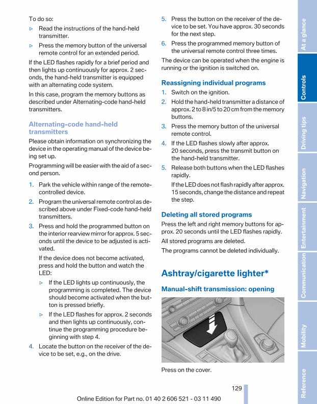
To do so:▷ Read the instructions of the hand-held
transmitter.▷ Press the memory button of the universal
remote control for an extended period.If the LED flashes rapidly for a brief period andthen lights up continuously for approx. 2 sec‐onds, the hand-held transmitter is equippedwith an alternating code system.In this case, program the memory buttons asdescribed under Alternating-code hand-heldtransmitters.
Alternating-code hand-heldtransmittersPlease obtain information on synchronizing thedevice in the operating manual of the device be‐ing set up.Programming will be easier with the aid of a sec‐ond person.
1. Park the vehicle within range of the remote-controlled device.
2. Program the universal remote control as de‐scribed above under Fixed-code hand-heldtransmitters.
3. Press and hold the programmed button onthe interior rearview mirror for approx. 5 sec‐onds until the device to be adjusted is acti‐vated.If the device does not become activated,press and hold the button and watch theLED:▷ If the LED lights up continuously, the
programming is completed. The deviceshould become activated when the but‐ton is pressed briefly.
▷ If the LED flashes for approx. 2 secondsand then lights up continuously, con‐tinue the programming procedure be‐ginning with step 4.
4. Locate the button on the receiver of the de‐vice to be set, e.g., on the drive.
5. Press the button on the receiver of the de‐vice to be set. You have approx. 30 secondsfor the next step.
6. Press the programmed memory button ofthe universal remote control three times.
The device can be operated when the engine isrunning or the ignition is switched on.
Reassigning individual programs1. Switch on the ignition.2. Hold the hand-held transmitter a distance of
approx. 2 to 8 in/5 to 20 cm from the memorybuttons.
3. Press the memory button of the universalremote control.
4. If the LED flashes slowly after approx.20 seconds, press the transmit button onthe hand-held transmitter.
5. Release both buttons when the LED flashesrapidly.If the LED does not flash rapidly after approx.15 seconds, change the distance and repeatthe step.
Deleting all stored programsPress the left and right memory buttons for ap‐prox. 20 seconds until the LED flashes rapidly.All stored programs are deleted.The programs cannot be deleted individually.
Ashtray/cigarette lighter*Manual-shift transmission: opening
Press on the cover.
Seite 129
129Online Edition for Part no. 01 40 2 606 521 - 03 11 490
Re
fere
nce
Mob
ility
Com
mun
icat
ion
Ente
rtain
men
tNa
vigat
ion
Drivi
ng ti
psCo
ntro
lsAt
a gl
ance

Automatic transmission*: opening
Press the button.
EmptyingTake out the insert.
LighterPush in the lighter.The lighter can be removed assoon as it pops back out.
Danger of burnsOnly hold the hot lighter by its knob; oth‐
erwise, there is the danger of getting burned.Switch off the ignition and take the remote con‐trol with you when leaving the vehicle so thatchildren cannot use the lighter and burn them‐selves.◀
Connecting electrical devicesSockets*The lighter socket can be used as a socket forelectrical equipment while the engine is runningor when the ignition is switched on. The totalload of all sockets must not exceed 140 Watt at12 V.Do not damage the socket by using unsuitableconnectors.
Manual transmission: center console
Press on the cover.Remove the cover or cigarette lighter*.
Automatic transmission*: centerconsole
Press on the cover.Remove the cover or cigarette lighter*.
Center armrest
Remove the cover.
Seite 130
130Online Edition for Part no. 01 40 2 606 521 - 03 11 490
Inte
rior e
quip
men
t
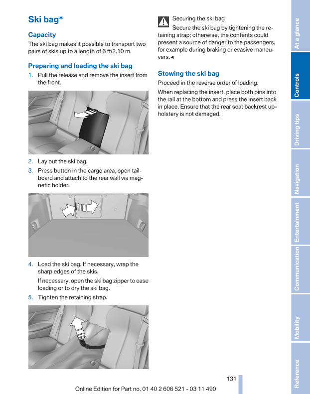
Ski bag*CapacityThe ski bag makes it possible to transport twopairs of skis up to a length of 6 ft/2.10 m.
Preparing and loading the ski bag1. Pull the release and remove the insert from
the front.
2. Lay out the ski bag.3. Press button in the cargo area, open tail‐
board and attach to the rear wall via mag‐netic holder.
4. Load the ski bag. If necessary, wrap thesharp edges of the skis.If necessary, open the ski bag zipper to easeloading or to dry the ski bag.
5. Tighten the retaining strap.
Securing the ski bagSecure the ski bag by tightening the re‐
taining strap; otherwise, the contents couldpresent a source of danger to the passengers,for example during braking or evasive maneu‐vers.◀
Stowing the ski bagProceed in the reverse order of loading.When replacing the insert, place both pins intothe rail at the bottom and press the insert backin place. Ensure that the rear seat backrest up‐holstery is not damaged.
Seite 131
131Online Edition for Part no. 01 40 2 606 521 - 03 11 490
Re
fere
nce
Mob
ility
Com
mun
icat
ion
Ente
rtain
men
tNa
vigat
ion
Drivi
ng ti
psCo
ntro
lsAt
a gl
ance

Storage compartmentsStorage compartmentsThe following storage compartments are avail‐able in the vehicle interior:▷ Glove compartment on the front passenger
side, refer to page 132.▷ Storage compartment on the center con‐
sole: manual transmission.▷ Storage compartment in the center armrest,
refer to page 132.▷ Compartments in the doors.▷ Pockets* on the backrests of the front seats.▷ Net* in the front passenger footwell.
Glove compartmentOpening
Pull the handle.The light in the glove compartment switches on.
Close the glove compartment again im‐mediately
Close the glove compartment immediately afteruse while driving; otherwise, injury may occurduring accidents.◀
ClosingFold up the cover.
USB interface for data transfer
Connection for importing and exporting data onUSB devices, e.g.:▷ Personal Profile settings, refer to page 33.▷ Music collection, refer to page 180.Observe the following when connecting:▷ Do not use force when plugging the con‐
nector into the USB interface.▷ Do not connect devices such as fans or
lamps to the USB interface.▷ Do not connect USB hard drives.▷ Do not use the USB interface to recharge
external devices.
Center armrestOpeningA storage compartment is located in the centerarmrest between the front seats.
Press the buttons next to the lock.
Seite 132
132Online Edition for Part no. 01 40 2 606 521 - 03 11 490
Stor
age
com
partm
ents

Locking the storage compartment
The storage compartment in the armrest can belocked with an integrated key to separately se‐cure the trunk lid, refer to page 39, for example.
After the storage compartment is locked, the re‐mote control can be handed out without theintegrated key, refer to page 32, for instance ata hotel.This prevents access to the storage compart‐ment and to the cargo area.
Connection for an external audiodevice
This can be used to connect an external audiodevice, such as a CD or MP3 player.
▷ AUX-IN port, refer to page 184.▷ USB audio interface*, refer to page 185.
CupholdersNotes
Shatter-proof containers and no hotdrinks
Use light and shatter-proof containers and donot transport hot drinks. Otherwise, there is theincreased danger of injury in an accident.◀
Unsuitable containersDo not forcefully push unsuitable contain‐
ers into the cupholders. This may result in dam‐age.◀
Manual transmission: center console
A cupholder is located on the center console.
Manual transmission: center armrest
A cupholder is located in the center armrestcompartment.To open: press the buttons next to the lock.
Seite 133
133Online Edition for Part no. 01 40 2 606 521 - 03 11 490
Re
fere
nce
Mob
ility
Com
mun
icat
ion
Ente
rtain
men
tNa
vigat
ion
Drivi
ng ti
psCo
ntro
lsAt
a gl
ance

Automatic transmission*: centerconsole
To open: press on the cover.
Storage compartments in thecargo areaNet*Small objects can be stowed in the net on therear cargo area trim.
Storage compartment under the cargofloor cover
Raise the cargo floor cover using the strap.
Lashing eyesTo secure the cargo, refer to page 141, thereare lashing eyes in the cargo area.
Seite 134
134Online Edition for Part no. 01 40 2 606 521 - 03 11 490
Stor
age
com
partm
ents

Seite 135
135Online Edition for Part no. 01 40 2 606 521 - 03 11 490
Re
fere
nce
Mob
ility
Com
mun
icat
ion
Ente
rtain
men
tNa
vigat
ion
Drivi
ng ti
psCo
ntro
lsAt
a gl
ance

Online Edition for Part no. 01 40 2 606 521 - 03 11 490

Driving tipsThis chapter provides you with information useful
in dealing with specific driving and operatingmodes.
Online Edition for Part no. 01 40 2 606 521 - 03 11 490

Things to remember when drivingBreaking-in periodGeneral informationMoving parts need to be broken in to adjust toeach other.The following instructions will help achieve along vehicle life and good economy.
Engine and differentialAlways obey the official speed limit.
Up to 1,200 miles/2,000 kmDo not exceed the maximum engine and roadspeed:▷ For gasoline engine, 4500 rpm and
100 mph/160 km/h.Avoid full-throttle operation and use of thetransmission's kickdown mode for the initialmiles.
From 1,200 miles/2,000 kmThe engine and vehicle speed can gradually beincreased.
TiresDue to technical factors associated with theirmanufacture, tires do not achieve their full trac‐tion potential until after an initial breaking-in pe‐riod.Drive conservatively for the first 200 miles/300 km.
Brake systemBrakes require an initial break-in period of ap‐prox. 300 miles/500 km to achieve optimizedcontact and wear patterns between brake padsand discs. Drive moderately during this break-inperiod.
ClutchThe function of the clutch reaches its optimallevel only after a distance driven of approx.
300 miles/500 km. During this break-in period,engage the clutch gently.
Following part replacementThe same breaking in procedures should be ob‐served if any of the components mentionedabove have to be renewed in the course of thevehicle's operating life.
General driving notesClosing the trunk lid
Drive with the trunk lid closedOnly drive with the tailgate closed; other‐
wise, in the event of an accident or braking orevasive maneuvers, passengers or other roadusers may be injured or the vehicle may be dam‐aged. In addition, exhaust fumes may enter thepassenger compartment.◀
If driving with the tailgate open cannot beavoided:▷ If the convertible top is closed, close all win‐
dows.▷ Greatly increase the blower speed.▷ Drive moderately.
Hot exhaust systemHot exhaust systemHigh temperatures are generated in the
exhaust system.Do not remove the heat shields installed andnever apply undercoating to them. When driv‐ing, standing at idle and while parking, take careto avoid possible contact between the hot ex‐haust system and any highly flammable materi‐als such as hay, leaves, grass, etc. Such contactcould lead to a fire, and with it the risk of seriouspersonal injury as well as property damage.Do not touch hot exhaust pipes; otherwise, thereis the danger of getting burned.◀
Seite 138
138Online Edition for Part no. 01 40 2 606 521 - 03 11 490
Thin
gs to
rem
embe
r whe
n dr
iving

Climate control windshield*
The marked area is not covered with heat re‐flective coating.Use this area for garage door openers, devicesfor electronic toll collection, etc.
Mobile communication devices in thevehicle
Mobile communication devices in the ve‐hicle
It is advised that you do not use mobile commu‐nication devices, e.g., mobile phones, inside thevehicle without connecting them directly to theexternal antenna. Otherwise, the vehicle elec‐tronics and mobile communication devices caninterfere with each other. In addition, there is noassurance that the radiation generated duringtransmission will be discharged from the vehicleinterior.◀
HydroplaningOn wet or slushy roads, a wedge of water canform between the tires and road surface.This phenomenon is referred to as hydroplan‐ing. It is characterized by a partial or completeloss of contact between the tires and the roadsurface, ultimately undermining your ability tosteer and brake the vehicle.
HydroplaningWhen driving on wet or slushy roads, re‐
duce your speed to prevent hydroplaning.◀
Driving through waterDrive though calm water only if it is not deeperthan 9.8 inches/25 cm and at this height, nofaster than walking speed, up to 6 mph/10 km/h.
Adhere to water depth and speed limita‐tions
Do not exceed this water depth and walkingspeed; otherwise, the vehicle's engine, the elec‐trical systems and the transmission may bedamaged.◀
Braking safelyYour vehicle is equipped with ABS as a standardfeature.Applying the brakes fully is the most effectiveway of braking in situations when this is neces‐sary.The vehicle maintains steering responsiveness.You can still avoid any obstacles with a minimumof steering effort.Pulsation of the brake pedal and sounds fromthe hydraulic circuits indicate that ABS is in itsactive mode.
Objects in the area around the pedalsNo objects in the area around the pedalsKeep floor mats, carpets, and any other
objects out of the area of motion of the pedals;otherwise, the function of the pedals could beimpeded while drivingDo not place additional floor mats over existingmats or other objects.Only use floor mats that have been approved forthe vehicle and can be properly fixed in place.Ensure that the floor mats are securely fastenedagain after they were removed for cleaning, forexample.◀
Driving in wet conditionsWhen roads are wet or there is heavy rain, brieflyexert gentle pressure on the brake pedal everyfew miles.Ensure that this action does not endanger otherroad users.
Seite 139
139Online Edition for Part no. 01 40 2 606 521 - 03 11 490
Re
fere
nce
Mob
ility
Com
mun
icat
ion
Ente
rtain
men
tNa
vigat
ion
Drivi
ng ti
psCo
ntro
lsAt
a gl
ance

The heat generated in this process helps dry thebrake discs and pads.In this way braking efficiency will be availablewhen you need it.
HillsDrive long or steep downhill gradients in the gearin which the least braking is required. Otherwise,the brake system may overheat, resulting in areduction in the brake system efficiency.Manual transmission:You can increase the engine's braking effect byshifting down, going all the way to first gear, ifnecessary.Automatic transmission*:You can increase the engine's braking effect byshifting down in the manual mode of the auto‐matic transmission, refer to page 72.
Avoid load on the brakesAvoid placing excessive load on the brake
system. Light but consistent brake pressure canlead to high temperatures, brake wear and pos‐sibly even brake failure.◀
Do not drive in neutralDo not drive in neutral or with the engine
stopped, as doing so disables engine braking. Inaddition, steering and brake assist is unavailablewith the engine stopped.◀
Brake disc corrosionCorrosion on the brake discs and contaminationon the brake pads are furthered by:▷ Low mileage.▷ Extended periods when the vehicle is not
used at all.▷ Infrequent use of the brakes.Corrosion occurs when the minimum pressurethat must be exerted by the pads during brakeapplications to clean the discs is not reached.Should corrosion form on the brake discs, thebrakes will tend to respond with a pulsating ef‐fect that generally cannot be corrected.
Condensation under the parked vehicleWhen using the automatic climate control, con‐densation water develops that exits underneaththe vehicle.Therefore, traces of condensed water under thevehicle are normal.
LoadingOverloading the vehicleTo avoid exceeding the approved carrying
capacity of the tires, never overload the vehicle.Overloading can lead to overheating and in‐creases the rate at which damage develops in‐side the tires. This could result in a sudden lossof tire inflation pressure.◀
No fluids in the trunkMake sure that fluids do not leak into the
trunk; otherwise, the vehicle may be damaged.◀
Determining the load limit
1. Locate the following statement on your ve‐hicle’s placard*:▷ The combined weight of occupants and
cargo should never exceed XXX kg orYYY lbs. Otherwise, damage to the ve‐hicle and unstable driving situations mayresult.
2. Determine the combined weight of thedriver and passengers that will be riding inyour vehicle.
3. Subtract the combined weight of the driverand passengers from XXX kilograms or YYYpounds.
Seite 140
140Online Edition for Part no. 01 40 2 606 521 - 03 11 490
Thin
gs to
rem
embe
r whe
n dr
iving

4. The resulting figure equals the availableamount of cargo and luggage load capacity.For example, if the YYY amount equals1,000 lbs and there will be four 150 lbs pas‐sengers in your vehicle, the amount of avail‐able cargo and luggage load capacity is400 lbs: 1,000 lbs minus 600 lbs = 400 lbs.
5. Determine the combined weight of luggageand cargo being loaded on the vehicle. Thatweight may not safely exceed the availablecargo and luggage load capacity calculatedin Step 4.
Load
The maximum load is the sum of the weight ofthe occupants and the cargo.The greater the weight of the occupants, theless cargo that can be transported.
Stowing cargo
▷ Heavy cargo: stow as far forward and as lowas possible, ideally directly behind the cargoarea separating wall.
▷ Very heavy cargo: when the rear seat is notoccupied, secure each of the outer safetybelts in the opposite buckle.
▷ Cover sharp edges and corners.
Securing cargo
Lashing eyes in the cargo area
To secure the cargo, there are four lashing eyesin the cargo area
Securing cargo▷ Smaller and lighter items: secure with re‐
taining straps or with a cargo net* or drawstraps.
▷ Larger and heavy objects: secure with cargostraps*.
Cargo straps, cargo netting, retaining straps ordraw straps on the lashing eyes in the cargoarea.
Securing cargoAlways position and secure the cargo as
described above; otherwise, it can endanger thecar's occupants if sudden braking or swervingbecomes necessary.Heavy or hard objects should not be carriedloose inside the car; otherwise, they could bethrown around as a result of hard braking, sud‐den swerves, etc., and endanger the occu‐pants.◀
Saving fuelGeneral informationYour vehicle contains advanced technology forthe reduction of fuel consumption and emis‐sions.Fuel consumption depends on a number of dif‐ferent factors.
Seite 141
141Online Edition for Part no. 01 40 2 606 521 - 03 11 490
Re
fere
nce
Mob
ility
Com
mun
icat
ion
Ente
rtain
men
tNa
vigat
ion
Drivi
ng ti
psCo
ntro
lsAt
a gl
ance
The implementation of certain measures, driv‐ing style and regular maintenance can have aninfluence on fuel consumption and on the envi‐ronmental impact.
Remove unnecessary cargoAdditional weight increases fuel consumption.
Remove attached parts following useAttached parts on the vehicle impair the aero‐dynamics and increase the fuel consumption.
Closing the windowsOpen windows increase air resistance andtherefore lead to greater fuel consumption.
Check the tire inflation pressureregularlyCheck and, if necessary, correct the tire inflationpressure at least twice a month and before start‐ing on a long trip.Low tire inflation pressure increases rolling re‐sistance and thus raises fuel consumption andtire wear.
Drive away without delayDo not wait for the engine to warm up while thevehicle remains stationary. Start driving rightaway, but at moderate engine speeds.This is the fastest way for the cold engine toreach its operating temperature.
Look well ahead when drivingAvoid unnecessary acceleration and braking.By maintaining a suitable distance to the vehicledriving ahead of you.Driving smoothly and looking ahead reducesfuel consumption.
Avoid high engine speedsUse 1st gear to get the vehicle in motion. Be‐ginning with 2nd gear, accelerate rapidly. Whenaccelerating, shift up before reaching high en‐gine speeds.
When you reach the desired speed, shift into thehighest applicable gear and drive with the en‐gine speed as low as possible and at a constantspeed.As a rule: driving at low engine speeds lowersfuel consumption and reduces wear.The gear shift indicator* of your vehicle indi‐cates the most fuel efficient gear.
Use coasting conditionsWhen approaching a red light, take your foot offthe accelerator and let the vehicle coast to a halt.On a downhill gradient, take your foot off the ac‐celerator and let the vehicle roll.The flow of fuel is interrupted while coasting.
Switch off the engine during longerstopsSwitch off the engine during longer stops, e.g.,at traffic lights, railroad crossings or in trafficcongestion.Fuel savings are achieved after the vehicle isswitched off for only approx. 4 seconds.
Switch off any functions that are notcurrently neededFunctions such as seat heating and the rear win‐dow defroster require a lot of energy and con‐sume additional fuel, especially in city and stop-and-go traffic.Therefore, switch off these functions if they arenot actually needed.
Have maintenance carried outHave vehicles maintained regularly to achieveoptimal vehicle economy and operating life.Have the maintenance carried out by your serv‐ice center.Please also note the BMW Maintenance Sys‐tem.
Seite 142
142Online Edition for Part no. 01 40 2 606 521 - 03 11 490
Thin
gs to
rem
embe
r whe
n dr
iving

Seite 143
143Online Edition for Part no. 01 40 2 606 521 - 03 11 490
Re
fere
nce
Mob
ility
Com
mun
icat
ion
Ente
rtain
men
tNa
vigat
ion
Drivi
ng ti
psCo
ntro
lsAt
a gl
ance

Online Edition for Part no. 01 40 2 606 521 - 03 11 490

NavigationThis chapter contains various examples of howthe navigation system can guide you reliably to
your destination.
Online Edition for Part no. 01 40 2 606 521 - 03 11 490
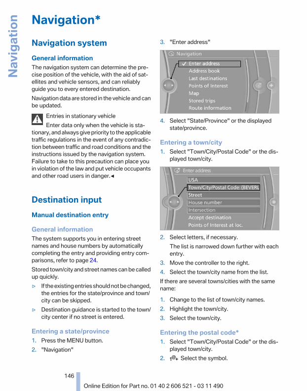
Navigation*Navigation systemGeneral informationThe navigation system can determine the pre‐cise position of the vehicle, with the aid of sat‐ellites and vehicle sensors, and can reliablyguide you to every entered destination.Navigation data are stored in the vehicle and canbe updated.
Entries in stationary vehicleEnter data only when the vehicle is sta‐
tionary, and always give priority to the applicabletraffic regulations in the event of any contradic‐tion between traffic and road conditions and theinstructions issued by the navigation system.Failure to take to this precaution can place youin violation of the law and put vehicle occupantsand other road users in danger.◀
Destination inputManual destination entry
General informationThe system supports you in entering streetnames and house numbers by automaticallycompleting the entry and providing entry com‐parisons, refer to page 24.Stored town/city and street names can be calledup quickly.▷ If the existing entries should not be changed,
the entries for the state/province and town/city can be skipped.
▷ Destination guidance is started to the town/city center if no street is entered.
Entering a state/province1. Press the MENU button.2. "Navigation"
3. "Enter address"
4. Select "State/Province" or the displayedstate/province.
Entering a town/city1. Select "Town/City/Postal Code" or the dis‐
played town/city.
2. Select letters, if necessary.The list is narrowed down further with eachentry.
3. Move the controller to the right.4. Select the town/city name from the list.If there are several towns/cities with the samename:
1. Change to the list of town/city names.2. Highlight the town/city.3. Select the town/city.
Entering the postal code*1. Select "Town/City/Postal Code" or the dis‐
played town/city.2. Select the symbol.
Seite 146
146Online Edition for Part no. 01 40 2 606 521 - 03 11 490
Navig
atio
n

3. Select the numbers.4. Change to the list of postal codes and towns/
cities.5. Highlight the entry.6. Selecting an entry.
Entering a street and intersection1. Select "Street" or the displayed street.2. Enter a street and intersection in the same
way as you would enter a town/city.If there are several streets with the same name:
1. Change to the list of street names.2. Highlight the street.3. Select the street.
Alternative: enter the street addressand house number1. Select "Street" or the displayed street.2. Enter the street as you would the town/city.3. "House number"4. Select the numbers.5. Change to the list of house numbers.6. Select a house number or range of house
numbers.
Street does not exist in the destinationcity/townThe desired street does not exist in the specifiedcity/town because it belongs to another part ofthe city/town.
1. "Navigation"2. "Enter address"3. Select "Street" or the displayed street.4. Change to the list of street names.5. Select "In" the displayed country.
All streets of the selected state/province areoffered. The associated town/city is dis‐played after the street name.
6. Select the letters.7. Change to the list of street names.8. Highlight the street.9. Select the street.
Starting destination guidance afterentering the destination1. "Accept destination"2. "Start guidance" or "Add as another
destination"Add a destination as a further destination,refer to page 152.
Address book
Selecting a destination from theaddress book1. "Navigation"2. "Address book"
Contacts with addresses are displayed ifthese have been checked as destinations.If the mobile phone* does not display thecontacts with addresses, they must first be
Seite 147
147Online Edition for Part no. 01 40 2 606 521 - 03 11 490
Re
fere
nce
Mob
ility
Com
mun
icat
ion
Ente
rtain
men
tNa
vigat
ion
Drivi
ng ti
psCo
ntro
lsAt
a gl
ance

checked as a destination, refer topage 217.
3. Select a contact in the list or, if desired, with"A-Z search".
4. "Business address" or "Home address"
Storing the destination in the addressbookAfter entering the destination, store the desti‐nation in the address book.
1. Open "Options".2. "Store as new contact" or "Add to existing
contact"
3. Select an existing contact, if available.4. "Business address" or "Home address"5. Enter "Last name" and, if necessary, "First
name".6. "Store in vehicle"
Storing the positionThe current position can be stored in the ad‐dress book.
1. "Navigation"2. Open "Options".
3. "Store position as contact" or "Add positionto contact"
4. Depending on the selection, choose an ex‐isting contact from the list. Select the typeof address and enter the first and last name.
5. "Store in vehicle"
Editing or deleting an address1. "Navigation"2. "Address book"3. Highlight the entry.4. Open "Options".5. "Edit in Contacts" or "Delete entry"
Using the home address as thedestinationThe home address must be stored. Specify thehome address, refer to page 216.
1. "Navigation"2. "Address book"3. "Home"
4. "Start guidance"
Seite 148
148Online Edition for Part no. 01 40 2 606 521 - 03 11 490
Navig
atio
n
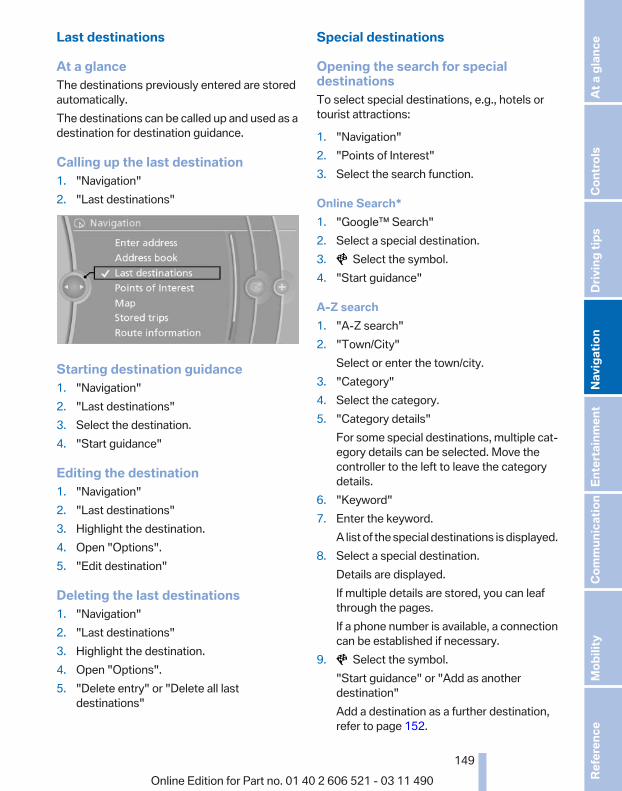
Last destinations
At a glanceThe destinations previously entered are storedautomatically.The destinations can be called up and used as adestination for destination guidance.
Calling up the last destination1. "Navigation"2. "Last destinations"
Starting destination guidance1. "Navigation"2. "Last destinations"3. Select the destination.4. "Start guidance"
Editing the destination1. "Navigation"2. "Last destinations"3. Highlight the destination.4. Open "Options".5. "Edit destination"
Deleting the last destinations1. "Navigation"2. "Last destinations"3. Highlight the destination.4. Open "Options".5. "Delete entry" or "Delete all last
destinations"
Special destinations
Opening the search for specialdestinationsTo select special destinations, e.g., hotels ortourist attractions:
1. "Navigation"2. "Points of Interest"3. Select the search function.
Online Search*1. "Google™ Search"2. Select a special destination.3. Select the symbol.4. "Start guidance"
A-Z search1. "A-Z search"2. "Town/City"
Select or enter the town/city.3. "Category"4. Select the category.5. "Category details"
For some special destinations, multiple cat‐egory details can be selected. Move thecontroller to the left to leave the categorydetails.
6. "Keyword"7. Enter the keyword.
A list of the special destinations is displayed.8. Select a special destination.
Details are displayed.If multiple details are stored, you can leafthrough the pages.If a phone number is available, a connectioncan be established if necessary.
9. Select the symbol."Start guidance" or "Add as anotherdestination"Add a destination as a further destination,refer to page 152.
Seite 149
149Online Edition for Part no. 01 40 2 606 521 - 03 11 490
Re
fere
nce
Mob
ility
Com
mun
icat
ion
Ente
rtain
men
tNa
vigat
ion
Drivi
ng ti
psCo
ntro
lsAt
a gl
ance

"Start search": if a search term is not entered,the search is repeated with the previous searchterm.
Category search1. "Category search"2. "Town/City"
Select or enter the town/city.3. "Category"4. Select the category.5. "Category details"
For some special destinations, multiple cat‐egory details can be selected. Move thecontroller to the left to leave the categorydetails.
6. "Start search"A list of the special destinations is displayed.
7. Select a special destination.Details are displayed.If multiple details are stored, you can leafthrough the pages.If a phone number is available, a connectioncan be established if necessary.
8. Select the symbol."Start guidance" or "Add as anotherdestination"Add a destination as a further destination,refer to page 152.
Display of special destinationsList of special destinations: special destinationsare organized by distance and are displayed witha directional arrow to the special destination.on the split screen, special destinations of theselected category are displayed in the map viewas symbols. The display depends on the scaleof the map and the category.
Destination entry via BMW Assist*A connection is established to the Conciergeservice, refer to page 219.
1. "Navigation"2. "Enter address"3. Open "Options".4. "BMW Assist dest. entry"
Displaying special destinations in themapTo display symbols of the special destinationsin the map view:
1. "Navigation"2. "Map"3. Open "Options".4. "Display Points of Interest"5. Select the setting.
Destination entry by map
Selecting the destination1. "Navigation"2. "Map"
The current position of the vehicle is indi‐cated on the map.
3. "Interactive map"
4. Select the destination with crosshairs.▷ To change the scale: turn the controller.▷ To shift the map: move the controller in
the required direction.▷ To shift the map diagonally: move the
controller in the required direction andturn it.
Seite 150
150Online Edition for Part no. 01 40 2 606 521 - 03 11 490
Navig
atio
n

Specifying the streetIf the system does not recognize a street, one ofthe following is displayed:▷ The name of a street in the vicinity.▷ The county.▷ The coordinates of the destination.
Additional functionsAdditional functions are available on the inter‐active map after the controller is pressed.
▷ Select the symbol."Start guidance" or "Add as anotherdestination"Add a destination as a further destination,refer to page 152.
▷ "Exit interactive map": return to the mapview.
▷ "View in northern direction" or "View indriving direction"
▷ "Display destination": the map sectionaround the destination is displayed.
▷ "Display current location": the map sectionaround your current location is displayed.
▷ "Find points of interest": the search for spe‐cial destinations is started.
Destination entry by voice*
General information▷ Instructions for voice activation system, re‐
fer to page 25.▷ When making a destination entry by voice,
you can change between voice operationand iDrive.
▷ To have the available spoken instructionsread out loud: ›Voice commands‹
Saying the entries▷ the town/city, street, and house number can
be entered as a single command*.▷ Countries, towns and cities, streets, and in‐
tersections can be said as whole words* orspelled in the language of the system, referto page 80.Example: to enter a town/city in a US stateas a whole word, the language of the systemmust be English.
▷ Spell the entry if the spoken language andthe language of the system differ.
▷ Say the letters smoothly, and avoid exag‐gerating the pronunciation and insertinglengthy pauses between the letters.
▷ The options available for entering data de‐pend on the navigation data and the countryand language settings.
entering an address using a command*
1. Press the button on the steeringwheel.
2. ›Enter address‹3. Wait for a request from the system.4. Say the address in the suggested order.5. Continue making the entry as prompted by
the system.If necessary, individually name the separatecomponents of the address, e.g., the town/city.
Entering a town/city separatelyThe name of the town/city can be said as aword* or spelled out.With the destination entry menu displayed:
1. Press the button on the steeringwheel.
2. ›City‹ or ›Spell city‹.3. Wait for the system to prompt you for the
town/city.
Seite 151
151Online Edition for Part no. 01 40 2 606 521 - 03 11 490
Re
fere
nce
Mob
ility
Com
mun
icat
ion
Ente
rtain
men
tNa
vigat
ion
Drivi
ng ti
psCo
ntro
lsAt
a gl
ance

4. Say the name of the town/city, or say at leastthe first three letters.Depending on the entry, up to 20 towns/cit‐ies may be suggested.
5. Select the town/city.▷ To select a recommended town/
city: ›Yes‹▷ To select a different town/city: ›New
entry‹▷ Select an entry: ›Entry ...‹ e.g., entry 2▷ To spell an entry: ›Spell city‹
6. Continue making the entry as prompted bythe system.
If there are several towns/cities with the samename:Towns/cities of the same name are grouped in alist and displayed as one location followed by anellipsis.
1. Select an entry: ›Yes‹ or ›Entry ...‹ e.g., En‐try 2.
2. Select the desired town/city.
Entering a street or intersectionseparatelyEnter a street and intersection in the same wayas you would enter a town/city.
Entering a house number separatelyDepending on the data in the navigation system,house numbers up to number 2000 can be en‐tered.
1. ›House number‹2. Say the house number.
Say each digit separately.3. Continue making the entry as prompted by
the system.
Planning a trip with intermediatedestinations
New tripA trip can be planned with several intermediatedestinations.
1. "Navigation"2. "Map"3. Move the controller to the left if necessary.4. "Guidance"5. "Enter new destination"6. Select the type of destination entry.
7. Enter the intermediate destination.8. "Start guidance"
Entering intermediate destinationsFor a trip, a max. of 30 intermediate destinationscan be entered.
1. "Enter new destination"2. Select the type of destination entry.3. Enter the intermediate destination.4. "Add as another destination"
The intermediate destination is entered inthe destination list and is highlighted.
5. Turn the controller until the intermediatedestination is located in the desired positionin the list.
6. Press the controller.
Starting the trip1. After all intermediate destinations are en‐
tered, highlight the first destination.If the second destination, for example, ishighlighted when destination guidance isstarted, the first destination is skipped.
2. "Start guidance" This symbol marks the active leg of the
trip.
Seite 152
152Online Edition for Part no. 01 40 2 606 521 - 03 11 490
Navig
atio
n

Store the tripUp to 30 trips can be stored in the trip list. Ifnecessary, delete existing trips to be able tostore new trips.
1. Open "Options".2. "Store trip"3. Enter the name.4. "OK"
Select the stored trip1. "Navigation"2. "Stored trips"3. Select a stored trip.4. "Start guidance"
Reversing the direction of travelIntermediate destinations are displayed in re‐verse order in the list.
1. "Map"2. "Guidance"3. Open "Options".4. "Reverse order of trip dest."
Intermediate destination options1. "Map"2. "Guidance"3. "Display all trip destinations"4. Select an intermediate destination.
▷ "Edit destination"▷ "Reposition dest. in the trip": move an
intermediate destination to another po‐sition in the list.
▷ "Delete dest. in the trip"▷ "Go to next dest. in the trip"
Some options are not available for certain trips.
Delete the stored trip1. "Stored trips"2. Highlight the desired trip.3. Open "Options".4. "Delete all trips" or "Delete trip"
Open the last trip1. "Navigation"2. "Stored trips"3. "Last trip"4. "Start guidance"
Destination guidanceStarting destination guidance1. "Navigation"2. Make a destination entry, refer to page 146.3. "Accept destination"4. "Start guidance"▷ The route is shown on the Control Display.▷ The distance to the destination/intermedi‐
ate destination and the estimated time of ar‐rival are displayed in the map view.
▷ The arrow view is shown in the instrumentcluster, in the Head-up Display*, and on theControl Display where appropriate.
Terminating destination guidance1. "Navigation"2. "Map"3. "Guidance"4. "Stop guidance"
Continuing destination guidanceIf the destination was not reached during the lasttrip, destination guidance can be resumed."Resume guidance"
Route criteria
General information▷ The route calculated can be influenced by
selecting certain criteria.▷ The route criteria can be changed when the
destination is entered and during destina‐tion guidance.
Seite 153
153Online Edition for Part no. 01 40 2 606 521 - 03 11 490
Re
fere
nce
Mob
ility
Com
mun
icat
ion
Ente
rtain
men
tNa
vigat
ion
Drivi
ng ti
psCo
ntro
lsAt
a gl
ance

▷ Road types are part of the navigation dataand are taken into consideration when plan‐ning a route, e.g., avoid highways.
▷ The recommended route may differ from theroute you would take based on personal ex‐perience.
▷ The settings are stored for the remote con‐trol currently in use.
▷ Destination guidance with traffic bulletins,refer to page 159.
Changing the route criteria1. "Navigation"2. "Map"3. "Route preference"4. Select the criterion:
▷ "Fast route": time-optimized route,being a combination of the shortest pos‐sible route and the fastest roads.
▷ "Efficient route": optimized combi‐nation of the fastest and shortest route.
▷ "Short route": short distance, irre‐spective of how fast or slow progress willbe.
▷ "Alternative routes": if available, alter‐native routes are suggested during ac‐tive route guidance. The individual sug‐gestions are highlighted in color.
5. Specify additional criteria for the route, ifnecessary:▷ "Avoid highways": highways are
avoided wherever possible.▷ "Avoid toll roads": toll roads are avoided
wherever possible.
▷ "Avoid ferries": ferries are avoidedwhere possible.
RouteDifferent views of the route are available duringdestination guidance:▷ Arrow view in the instrument cluster and on
the Control Display.▷ List of route sections.▷ Map view, refer to page 155.▷ Arrow view in the Head-up Display*, refer to
page 121.
Arrow viewThe following information is displayed duringdestination guidance:▷ Large arrow: current direction of travel.▷ Small arrow: indicates the next change in di‐
rection.▷ Intersection view.▷ Lane information.▷ Traffic bulletins.▷ Distance to the next change in direction.▷ Street name at the next change in direction.
Lane informationOn multi-lane roads, the recommended lanesare marked in the arrow view by a triangle.▷ Solid triangle: best lane.▷ Empty triangle: possible lane. However, an‐
other lane change may be needed shortly.
Displaying list of route sectionsWhen the destination guidance is started, a listof route sections can be displayed. The drivingdistances and traffic bulletins are displayed foreach route section.
1. "Navigation"2. "Route information"3. Mark route section.
The route section is displayed on the splitscreen.
Seite 154
154Online Edition for Part no. 01 40 2 606 521 - 03 11 490
Navig
atio
n

Bypassing a section of the routeCalculate a new route for a route section.
1. "Navigation"2. "Route information"3. "New route for"
4. Turn the controller. Enter the number of kilo‐meters within which you would like to returnto the original route.
5. Press the controller.
Resuming the original routeIf the route section should no longer be by‐passed:
1. "Navigation"2. "Route information"3. "New route for:"4. "Remove blocking"
Gas station recommendationThe remaining range is calculated, and if nec‐essary gas stations along the route are dis‐played.
1. "Navigation"2. "Route information"3. "Recommended refuel"
A list of the gas stations is displayed.4. Highlight a gas station.
The position of the gas station is displayedon the split screen.
5. Select the gas station.
6. Select the symbol.7. "Start guidance": destination guidance to
the selected gas station is started."Add as another destination": the gas sta‐tion is added to the route.
Switching spoken instructions on/offThe setting is stored for the remote control cur‐rently in use.
1. "Navigation"2. "Map"3. "Voice instructions"
Repeating spoken instructions1. "Navigation"2. "Map"3. Highlight the symbol.4. Press the controller twice.
Volume of spoken instructionsTurn the volume button while giving an instruc‐tion until the desired volume is set.
Saving the spoken instructions on theprogrammable memory buttonsThe function for switching the spoken instruc‐tions on/off can be stored on a programmablememory button, refer to page 23, for quick ac‐cess.
Map viewSelecting the map view1. "Navigation"2. "Map"
Seite 155
155Online Edition for Part no. 01 40 2 606 521 - 03 11 490
Re
fere
nce
Mob
ility
Com
mun
icat
ion
Ente
rtain
men
tNa
vigat
ion
Drivi
ng ti
psCo
ntro
lsAt
a gl
ance

At a glance
1 Function bar2 Route section with traffic obstruction3 Traffic sign for traffic obstruction4 Planned route5 Current location6 Upper status field7 Lower status field
Lines in the mapStreets and routes are displayed in different col‐ors and styles depending on their classification.Dashed lines represent railways and ferry con‐nections. Country borders are indicated by thinlines.
Traffic obstructionsSmall triangles along the planned route indicateroute sections with traffic obstructions, depend‐ing on the map scale. The direction of the trian‐gles indicates the direction of the obstruction.The traffic signs indicate the significance of theobstruction.▷ Red traffic sign: the obstruction affects the
planned route or direction.▷ Gray traffic sign: the obstruction does not
affect the planned route or direction.Traffic bulletins, refer to page 157.
Planned routeAfter destination guidance is started, the plan‐ned route is displayed on the map.
Status fieldsShow/hide: press the controller.
▷ Upper status field: time, telephone, and en‐tertainment details.
▷ Lower status field: symbol for active desti‐nation guidance, status of traffic bulletins,time of arrival, and distance to destination.
Function barThe following functions are available in the func‐tion bar:
Symbol Function
Start/end destination guidance.
Switch spoken instructions on/off.
Change the route criteria.
Search for a special destination.
Display the traffic bulletins.
Interactive map.
Set the map view.
Change the scale.
To change to the function bar, move the con‐troller to the left.
Changing the map section "Interactive map"
▷ To shift the map: move the controller in therequired direction.
▷ To shift the map diagonally: move the con‐troller in the required direction and turn it.
Changing the scale1. Select the symbol.2. To change the scale: turn the controller.
Automatically scaled map scaleIn the map view facing north, turn the controllerin any direction until the AUTO scale is dis‐played. The map shows the entire route be‐tween the current location and the destination.
Seite 156
156Online Edition for Part no. 01 40 2 606 521 - 03 11 490
Navig
atio
n
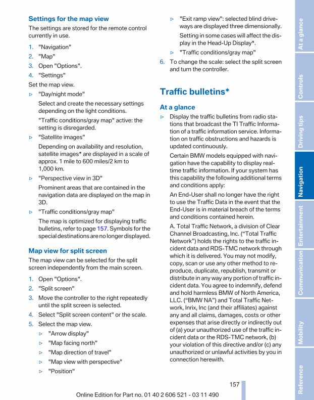
Settings for the map viewThe settings are stored for the remote controlcurrently in use.
1. "Navigation"2. "Map"3. Open "Options".4. "Settings"Set the map view.▷ "Day/night mode"
Select and create the necessary settingsdepending on the light conditions."Traffic conditions/gray map" active: thesetting is disregarded.
▷ "Satellite images"Depending on availability and resolution,satellite images* are displayed in a scale ofapprox. 1 mile to 600 miles/2 km to1,000 km.
▷ "Perspective view in 3D"Prominent areas that are contained in thenavigation data are displayed on the map in3D.
▷ "Traffic conditions/gray map"The map is optimized for displaying trafficbulletins, refer to page 157. Symbols for thespecial destinations are no longer displayed.
Map view for split screenThe map view can be selected for the splitscreen independently from the main screen.
1. Open "Options".2. "Split screen"3. Move the controller to the right repeatedly
until the split screen is selected.4. Select "Split screen content" or the scale.5. Select the map view.
▷ "Arrow display"▷ "Map facing north"▷ "Map direction of travel"▷ "Map view with perspective"▷ "Position"
▷ "Exit ramp view": selected blind drive‐ways are displayed three dimensionally.Setting in some cases will affect the dis‐play in the Head-Up Display*.
▷ "Traffic conditions/gray map"6. To change the scale: select the split screen
and turn the controller.
Traffic bulletins*At a glance▷ Display the traffic bulletins from radio sta‐
tions that broadcast the TI Traffic Informa‐tion of a traffic information service. Informa‐tion on traffic obstructions and hazards isupdated continuously.Certain BMW models equipped with navi‐gation have the capability to display real-time traffic information. If your system hasthis capability the following additional termsand conditions apply:An End-User shall no longer have the rightto use the Traffic Data in the event that theEnd-User is in material breach of the termsand conditions contained herein.A. Total Traffic Network, a division of ClearChannel Broadcasting, Inc. (“Total TrafficNetwork”) holds the rights to the traffic in‐cident data and RDS-TMC network throughwhich it is delivered. You may not modify,copy, scan or use any other method to re‐produce, duplicate, republish, transmit ordistribute in any way any portion of traffic in‐cident data. You agree to indemnify, defendand hold harmless BMW of North America,LLC. (“BMW NA”) and Total Traffic Net‐work, Inrix, Inc (and their affiliates) againstany and all claims, damages, costs or otherexpenses that arise directly or indirectly outof (a) your unauthorized use of the traffic in‐cident data or the RDS-TMC network, (b)your violation of this directive and/or (c) anyunauthorized or unlawful activities by you inconnection herewith.
Seite 157
157Online Edition for Part no. 01 40 2 606 521 - 03 11 490
Re
fere
nce
Mob
ility
Com
mun
icat
ion
Ente
rtain
men
tNa
vigat
ion
Drivi
ng ti
psCo
ntro
lsAt
a gl
ance

B. Total Traffic Network traffic data is infor‐mational only. User assumes all risk of use.Total Traffic Network, BMW NA, and theirsuppliers make no representations aboutcontent, traffic and road conditions, routeusability, or speed.C. The licensed material is provided to li‐censee “as is,” and “where is”. Total TrafficNetwork, including, but not limited to, anyand all third party providers of any of the li‐censed material, expressly disclaims, to thefullest extent permitted by law, all warrantiesor representations with respect to the li‐censed material (including, without limita‐tion, that the licensed material will be error-free, will operate without interruption or thatthe traffic data will be accurate), express, im‐plied or statutory, including, without limita‐tion, the implied warranties of merchanta‐bility, non-infringement fitness for aparticular purpose, or those arising from acourse of dealing or usage of trade.D. Neither Total Traffic Network, Inrix, Inc. orBMW NA will be liable to you for any indirect,special, consequential, exemplary, or inci‐dental damages (including, without limita‐tion, lost revenues, anticipated revenues, orprofits relating to the same) arising from anyclaim relating directly or indirectly to use ofthe traffic data, and even if Total Traffic Net‐work, Inrix, Inc., or BMW NA are aware of thepossibility of such damages. These limita‐tions apply to all claims, including, withoutlimitation, claims in contract and tort (suchas negligence, product liability and strict li‐ability). Some states do not allow the exclu‐sion or limitation of incidental or consequen‐tial damages, so those particular limitationsmay not apply to you.
▷ The traffic bulletins are indicated on the mapby symbols.
▷ The traffic bulletins for the surrounding areaare stored in a list.
The symbol in the function bar of the mapview turns red if there are traffic bulletinsthat affect the calculated route.
Switching the reception on/off1. "Navigation"2. Open "Options".3. "Receive Traffic Info"
Open the traffic bulletins1. "Navigation"2. "Map"3. "Traffic Info"
First the traffic bulletins for the calculatedroute are displayed.The traffic bulletins are sorted by their dis‐tance from the current position of the vehi‐cle.
4. Select a traffic bulletin. "More information": display additional
information.5. Scroll to the next or previous traffic bulletin
if required.
Traffic bulletins on the map"Traffic conditions/gray map" Active: indicationon the control display is switched to shades ofgray. This enables a better view of the trafficbulletins. The day/night mode is disregarded inthis setting. Symbols and special destinationsare not displayed.
1. "Navigation"2. "Map"3. Open "Options".4. "Settings"5. "Traffic conditions/gray map"
Symbols in the map viewDepending on the scale of the map and the lo‐cation of the traffic obstruction along the route,the symbols for the traffic obstructions are dis‐played.
Additional information in the map viewDepending on the map scale, a traffic obstruc‐tion's length, direction, and impact are displayed
Seite 158
158Online Edition for Part no. 01 40 2 606 521 - 03 11 490
Navig
atio
n

in the map using triangles or gray bars along thecalculated route.▷ Red: congestion.▷ Orange: stop-and-go traffic.▷ Yellow: heavy traffic.▷ Green: clear roads.▷ Gray: general traffic bulletins, e.g., construc‐
tion site.The displayed information depends on the par‐ticular traffic information service.
Filtering traffic bulletinsYou can set which traffic bulletins appear on themap.
1. "Navigation"2. "Map"3. Open "Options".4. "Traffic Info categories"5. Select the desired categories.
Traffic bulletins of the selected category are dis‐played on the map.▷ Traffic bulletins that are relevant to the route
are always shown.▷ For your own safety, traffic bulletins that no‐
tify you of potentially dangerous situations,such as wrong-way drivers, cannot be hid‐den.
Destination guidance with trafficbulletins
Semi-dynamic destination guidanceWhen traffic bulletin reception is switched on,semi-dynamic destination guidance is active.
The destination guidance system takes theavailable traffic information into account. A mes‐sage is displayed depending on the route, thetraffic bulletins, and the possible detour routes.A detour is suggested in the event of a trafficobstruction. In addition, distance and time dif‐ferences between the original route and the de‐tour are displayed.To accept the detour:
"Detour"In the event of special hazards, e.g., objects onthe road, a message is displayed without a de‐tour suggestion.Detours can also be accepted if the traffic mes‐sages are called up in the list.
1. "Navigation"2. "Map"3. "Traffic Info"4. "Detour information"5. "Detour"
Dynamic destination guidanceThe route is automatically changed in the eventof traffic obstructions.▷ The system does not point out traffic ob‐
structions along the original route.▷ Traffic bulletins continue to be displayed on
the map.▷ Depending on road type and the kind and
extent of the traffic obstruction, the calcu‐lated route may lead through the traffic ob‐struction.
▷ Dangerous situations are displayed regard‐less of the setting.
To activate dynamic destination guidance:
1. "Navigation"2. Open "Options".3. "Dynamic guidance"
Seite 159
159Online Edition for Part no. 01 40 2 606 521 - 03 11 490
Re
fere
nce
Mob
ility
Com
mun
icat
ion
Ente
rtain
men
tNa
vigat
ion
Drivi
ng ti
psCo
ntro
lsAt
a gl
ance

Navigation dataInformation on the navigation data1. "Navigation"2. Open "Options".3. "Navigation system version": information on
the data version is displayed.
Updating the navigation data
General informationNavigation data and authorization codes areavailable from your service center. Navigationdata are stored in the vehicle and can be up‐dated.▷ Depending on the data volume, a data up‐
date may take several hours.▷ Update during the trip to preserve battery.▷ During the update, only the basic functions
of the navigation system are available.▷ The status of the update can be viewed.▷ The system restarts after the update.▷ The data carrier with the navigation data can
be removed after the update is complete.
Perform an update1. Insert the navigation DVD into the DVD
player with the labeled side facing up.2. Follow the instructions on the Control Dis‐
play.3. Enter the authorization code of the naviga‐
tion DVD and change the DVD if needed.After interrupting your trip, follow the instruc‐tions on the Control Display.
Viewing the status
1. Press the button.2. "Navigation update"
What to do if...▷ The current transmission position cannot be
displayed?The vehicle is located in an unrecognizedregion, is in a poor reception area, or thesystem is currently determining the posi‐tion. Reception is usually best when youhave an unobstructed view of the sky.
▷ The destination without street information isnot used for route guidance?When city has been input, no downtown canbe determined.Input any street in the selected city and startdestination guidance.
▷ The destination is not used for route guid‐ance?The destination data is not contained in thenavigation data. Select a destination that isas close as possible to the original.
▷ Letters for destination input cannot be se‐lected?The stored data do not contain the data ofthe destination.Select a goal that is as close as possible tothe original.
▷ Is the map displayed in shades of gray?"Traffic conditions/gray map" Active: indi‐cation on the control display is switched toshades of gray. This enables a better view ofthe traffic bulletins.
▷ Spoken instructions are no longer outputduring route guidance in front of intersec‐tions?The area has not yet been fully recorded, oryou have left the recommended route andthe system requires a few seconds to cal‐culate a new route suggestion.
Seite 160
160Online Edition for Part no. 01 40 2 606 521 - 03 11 490
Navig
atio
n

Seite 161
161Online Edition for Part no. 01 40 2 606 521 - 03 11 490
Re
fere
nce
Mob
ility
Com
mun
icat
ion
Ente
rtain
men
tNa
vigat
ion
Drivi
ng ti
psCo
ntro
lsAt
a gl
ance

Online Edition for Part no. 01 40 2 606 521 - 03 11 490

EntertainmentThe chapter helps assure your enjoyment when
receiving radio and television stations and playingCDs, DVDs and tracks from the music collection.
Online Edition for Part no. 01 40 2 606 521 - 03 11 490
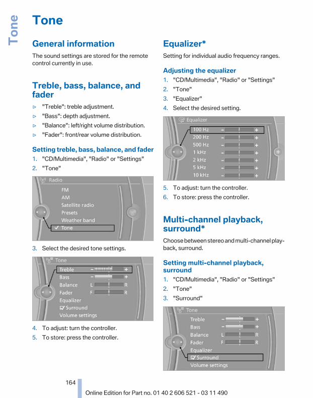
ToneGeneral informationThe sound settings are stored for the remotecontrol currently in use.
Treble, bass, balance, andfader▷ "Treble": treble adjustment.▷ "Bass": depth adjustment.▷ "Balance": left/right volume distribution.▷ "Fader": front/rear volume distribution.
Setting treble, bass, balance, and fader1. "CD/Multimedia", "Radio" or "Settings"2. "Tone"
3. Select the desired tone settings.
4. To adjust: turn the controller.5. To store: press the controller.
Equalizer*Setting for individual audio frequency ranges.
Adjusting the equalizer1. "CD/Multimedia", "Radio" or "Settings"2. "Tone"3. "Equalizer"4. Select the desired setting.
5. To adjust: turn the controller.6. To store: press the controller.
Multi-channel playback,surround*Choose between stereo and multi-channel play‐back, surround.
Setting multi-channel playback,surround1. "CD/Multimedia", "Radio" or "Settings"2. "Tone"3. "Surround"
Seite 164
164Online Edition for Part no. 01 40 2 606 521 - 03 11 490
Tone
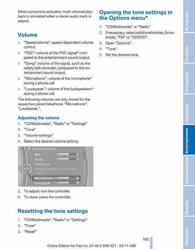
When surround is activated, multi-channel play‐back is simulated when a stereo audio track isplayed.
Volume▷ "Speed volume": speed-dependent volume
control.▷ "PDC": volume of the PDC signal* com‐
pared to the entertainment sound output.▷ "Gong": volume of the signal, such as the
safety belt reminder, compared to the en‐tertainment sound output.
▷ "Microphone": volume of the microphone*during a phone call.
▷ "Loudspeak.": volume of the loudspeakers*during a phone call.
The following volumes are only stored for therespective paired telephone: "Microphone","Loudspeak.".
Adjusting the volume1. "CD/Multimedia", "Radio" or "Settings"2. "Tone"3. "Volume settings"4. Select the desired volume setting.
5. To adjust: turn the controller.6. To store: press the controller.
Resetting the tone settings1. "CD/Multimedia", "Radio" or "Settings"2. "Tone"3. "Reset"
Opening the tone settings inthe Options menu*1. "CD/Multimedia" or "Radio"2. If necessary, select additional entries, for ex‐
ample, "FM" or "CD/DVD".3. Open "Options".4. "Tone"5. Set the desired tone.
Seite 165
165Online Edition for Part no. 01 40 2 606 521 - 03 11 490
Re
fere
nce
Mob
ility
Com
mun
icat
ion
Ente
rtain
men
tNa
vigat
ion
Drivi
ng ti
psCo
ntro
lsAt
a gl
ance

RadioControls
1 Change entertainment sources2 Change station/track3 Programmable memory buttons4 Volume, on/off5 Change wave band
Sound outputSwitching on/offWhen the ignition is switched off: press ON/OFFbutton on the radio.
MutingWhen the ignition is switched on or the engineis running: press the ON/OFF button on theradio.
AM/FM stationSelecting a station1. "Radio"2. "FM" or "AM"
3. Select the desired station.
All saved stations are stored for the remote con‐trol currently in use.
Changing the station via the buttonPress the button.
Storing a station1. "Radio"2. "FM" or "AM"3. Highlight the desired station.
4. Press the controller for an extended period.5. Select the desired memory location.The stations are stored for the remote controlcurrently in use.The stations can also be stored on the program‐mable memory buttons, refer to page 23.
Selecting a station manuallyStation selection via the frequency.
Seite 166
166Online Edition for Part no. 01 40 2 606 521 - 03 11 490
Radi
o

1. "Radio"2. "FM" or "AM"3. "Manual"4. To select the frequency: turn the controller.
To store the station: press the controller for anextended period.
RDS*RDS broadcasts additional information, such asthe station name, in the FM wave band. Whenplaying a station with multiple frequencies, thesystem automatically switches to the frequencywith the best reception, if needed.
Switching the RDS on/off1. "Radio"2. "FM"3. Open "Options".4. "RDS"
The setting is stored for the remote control cur‐rently in use.
HD Radio™ reception*Many stations broadcast both analog and digitalsignals.License conditions
HD Radio™ technology manufactured under li‐cense from iBiquity Digital Corp. U. S. and For‐eign Patents. HD Radio™ and the HD and HDRadio logos are proprietary trademarks of iBiq‐uity Digital Corp.
Activating/deactivating digital radioreception1. "Radio"2. "FM" or "AM"3. Open "Options".4. "HD Radio Reception"The setting is stored for the remote control cur‐rently in use.
This symbol is displayed in the status linewhen the audio signal is digital.In areas in which the station is not continuouslyreceived in digital mode, the playback switchesbetween analog and digital reception. Due totime delayed broadcasting, there may be repe‐titions or interruptions. In this case, switch offdigital radio reception.
Displaying additional informationSome stations broadcast additional informationon the current track, such as the name of the ar‐tist.
1. Select the desired station.2. Open "Options".3. "Station info"
Selecting a substation This symbol indicates that a main station also
broadcasts additional substations. The stationname of the main station ends in HD1. Stationnames of the substations end in HD2, HD3, etc.
1. Select the desired station.2. Press the controller.3. Select the substation.When reception is poor, the substation is mutedfor several seconds. If reception is interruptedfor an extended period, it switches back to themain station.
Seite 167
167Online Edition for Part no. 01 40 2 606 521 - 03 11 490
Re
fere
nce
Mob
ility
Com
mun
icat
ion
Ente
rtain
men
tNa
vigat
ion
Drivi
ng ti
psCo
ntro
lsAt
a gl
ance

Weather Band*General informationThe availability of the Weather Band and thenumber of available channels can vary depend‐ing on the region.
Switching on the Weather Band1. "Radio"2. "Weather band"3. Select the desired channel.
Additional informationWeather Band is a service of the National Oce‐anic and Atmospheric Administration (NOAA).Additional information on the Internet:www.nws.noaa.gov.
Satellite radio*General informationThe channels are offered in predefined pack‐ages. The packages must be enabled by tele‐phone.
Navigation bar overview
Symbol Function
Change the list view.
Select the category.
Direct channel entry
Timeshift
Open the My Favorites category/open a favorite.
Manage the favorites.
Traffic Jump
The functions of the navigation bar symbols canalso be stored on the programmable memorybuttons, refer to page 23.
Managing a subscriptionTo be able to enable or unsubscribe from thechannels, you must have reception. It is usuallyat its best when you have an unobstructed viewof the sky. The channel name is displayed in thestatus line.
Enabling channelsThe Unsubscribed Channels category containsall disabled channels.
1. "Radio"2. "Satellite radio"3. "Category"
4. Select the Unsubscribed Channels cate‐gory.
5. Select the desired channel.The phone number and an electronic serialnumber, ESN, are displayed.
6. Select the phone number to have the chan‐nel enabled.
You can unsubscribe from the channels againvia this phone number.
Unsubscribing from channels1. "Radio"2. "Satellite radio"
Seite 168
168Online Edition for Part no. 01 40 2 606 521 - 03 11 490
Radi
o

3. Open "Options".4. "Manage subscription"
5. The phone number and an electronic serialnumber, ESN, are displayed.
6. Call Sirius to unsubscribe from the chan‐nels.
Selecting channelsYou can only listen to enabled channels.The selected channel is stored for the remotecontrol currently in use.
Via iDrive1. "Radio"2. "Satellite radio"3. Select "All channels" or the desired cate‐
gory.4. Select the desired channel.
Via the buttons on the center consolePress the button.The next channel is selected.
Via direct channel entry1. "Radio"2. "Satellite radio"3. "Set channel"4. Turn the controller until the desired channel
is reached and press the controller.
Storing a channel1. "Radio"2. "Satellite radio"3. If necessary, open "All channels" or the de‐
sired category.4. Select the desired channel.5. Press the controller again.6. Press the controller again to confirm the
highlighted channel.
7. Select the desired memory location.The channels are stored for the remote controlcurrently in use.The channels can also be stored on the pro‐grammable memory buttons, refer to page 23.
Changing the list viewThe list view changes every time the first symbolon the navigation bar is pressed.Information on the channel is displayed.
Symbol Meaning
Channel name
Artist
Track
Seite 169
169Online Edition for Part no. 01 40 2 606 521 - 03 11 490
Re
fere
nce
Mob
ility
Com
mun
icat
ion
Ente
rtain
men
tNa
vigat
ion
Drivi
ng ti
psCo
ntro
lsAt
a gl
ance

Selecting a category1. "Radio"2. "Satellite radio"3. "Category"4. Select the desired category.
TimeshiftApprox. one hour of the program being broad‐cast on the channel currently being listened tois stored in a buffer. Prerequisite: the signal mustbe available.The stored audio track can be played with a de‐lay following the live broadcast. When the bufferis full, the older tracks are overwritten. The buf‐fer is cleared when a new channel is selected.
Opening the timeshift function1. "Radio"2. "Satellite radio"3. "Replay - Time shift"
▷ The red arrow shows the current playbackposition.
▷ The time difference to the live broadcast isdisplayed next to the buffer bar.For live transmissions: "live".
Timeshift menu
Symbol Function
Go to the live broadcast
Playback/pause
Next track
Previous track
Symbol Function
Fast forward
Reverse
Automatic timeshift deactivated/ac‐tivated
Automatic timeshiftWhen the function is activated, audio playbackis stopped automatically in the event of:▷ Incoming and outgoing telephone calls.▷ Activation of the voice activation system.▷ Muting.The audio playback then continues with a timedelay.To activate:
1. "Radio"2. "Satellite radio"3. "Replay - Time shift"4. "Automatic time shift"To deactivate: "Automatic time shift".
Storing favoritesUp to 30 favorites can be stored in the favoriteslist. Available favorites are artist, track, game,league, and team.
Storing the artist, track, or gameIt is only possible to store favorites that are cur‐rently being broadcast. The channel informationmust be available.
1. "Radio"2. "Satellite radio"3. If necessary, open "All channels" or the de‐
sired category.4. Select the desired channel.5. Press the controller again.6. Select the artist, track, or game.
Seite 170
170Online Edition for Part no. 01 40 2 606 521 - 03 11 490
Radi
o

Storing the league or teamLeagues or teams can be added to the favoritesfrom a selection list.
1. "Radio"2. "Satellite radio"3. "Manage favorites"4. "Add sports information"
5. Select the league.6. Select "Add all teams" or the desired team.
Opening the favoritesIf an activated favorite is played back, the fol‐lowing message appears for approx. 20 sec‐onds: "Favorite alert!".
"Favorites"Select the symbol while the message is shown.
The displayed favorite is played.If there is no message, the system changes tothe My Favorites category. All favorites currentlybeing broadcast can be selected from a list.
Managing the favorites
Activating/deactivating the favoritesFavorites can be activated and deactivatedglobally and individually.
1. "Satellite radio"2. "Manage favorites"3. Select "Activate alert" or the desired favor‐
ites.The setting is stored for the remote control cur‐rently in use.
Deleting favorites1. "Satellite radio"2. "Manage favorites"3. Highlight the desired favorite.4. Open "Options".5. "Delete entry"
Traffic JumpTraffic and weather information for a selectedregion is broadcast every few minutes.
Selecting a region1. "Radio"2. "Satellite radio"3. Open "Options".4. "Set jump"5. Select the desired region.The region is stored for the remote control cur‐rently in use.
Activating/deactivating the jump1. "Radio"2. "Satellite radio"3. "Jump to:"Information for the selected region is broadcastas soon as it is available.A new panel opens.Canceling the Traffic Jump: "Cancel".
Symbol Meaning
Information will be broadcast shortly.
Information is currently being broad‐cast.
Seite 171
171Online Edition for Part no. 01 40 2 606 521 - 03 11 490
Re
fere
nce
Mob
ility
Com
mun
icat
ion
Ente
rtain
men
tNa
vigat
ion
Drivi
ng ti
psCo
ntro
lsAt
a gl
ance

Select one of the symbols to deactivate TrafficJump.
Automatic updateAbout twice a year, Sirius performs an update ofthe channel names and positions. The updatetakes place automatically and may take severalminutes.
Notes▷ Reception may not be available in some sit‐
uations, such as under certain environmen‐tal or topographic conditions. The satelliteradio has no influence on this.
▷ The signal may not be available in tunnels orunderground garages next to tall buildingsor near trees, mountains or other powerfulsources of radio interference.
Stored stationsGeneral informationIt is possible to store up to 40 stations.
Calling up a station1. "Radio"2. "Presets"3. Select the desired station.
Storing a stationThe station currently selected is stored.
1. "Radio"2. "Presets"
3. "Store station"
4. Select the desired memory location.The list of stored stations is stored for the re‐mote control currently in use.The stations can also be stored on the program‐mable memory buttons, refer to page 23.
Deleting a station1. "Radio"2. "Presets"3. Select the desired station.4. Open "Options".5. "Delete entry"
Seite 172
172Online Edition for Part no. 01 40 2 606 521 - 03 11 490
Radi
o

CD/multimediaControls
1 Change the entertainment source2 CD/DVD* drive3 Eject CD/DVD4 Change station/track5 Programmable memory buttons6 Volume, on/off
Sound outputSwitching on/offWhen the ignition is switched off: press ON/OFFbutton on the radio.
MutingWhen the ignition is switched on or the engineis running: press the ON/OFF button on theradio.
CD/DVD*Playback
Filling the CD/DVD* playerInsert the CD/DVD with the printed side up.Playback begins automatically.Reading can take a few minutes with com‐pressed audio files.
Starting playbackA CD/DVD is located in the CD/DVD player orDVD changer*.
1. "CD/Multimedia"2. "CD/DVD"3. Select the desired CD or DVD.
Symbol Meaning
CD/DVD* player
... DVD changer*
Playable formats▷ DVD: DVD-ROM, DVD-R, DVD+R, DVD-
RW, DVD+RW, DVD-R DL, DVD+R DL, DVDaudio (video part only), DVD video*.
▷ CD: CD-ROM, CD-R, CD-RW, CD-DA,VCD*, SVCD*.
▷ Compressed audio files: MP3, WMA, AAC*,M4A*.
Audio playback
Selecting the track using the buttonPress the button repeatedly until thedesired track is played.
Seite 173
173Online Edition for Part no. 01 40 2 606 521 - 03 11 490
Re
fere
nce
Mob
ility
Com
mun
icat
ion
Ente
rtain
men
tNa
vigat
ion
Drivi
ng ti
psCo
ntro
lsAt
a gl
ance
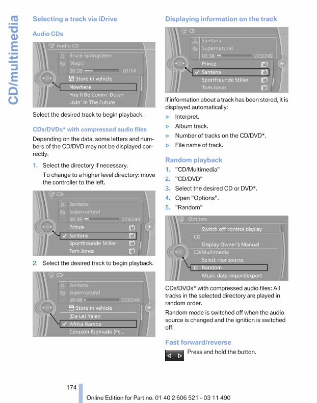
Selecting a track via iDrive
Audio CDs
Select the desired track to begin playback.
CDs/DVDs* with compressed audio filesDepending on the data, some letters and num‐bers of the CD/DVD may not be displayed cor‐rectly.
1. Select the directory if necessary.To change to a higher level directory: movethe controller to the left.
2. Select the desired track to begin playback.
Displaying information on the track
If information about a track has been stored, it isdisplayed automatically:▷ Interpret.▷ Album track.▷ Number of tracks on the CD/DVD*.▷ File name of track.
Random playback1. "CD/Multimedia"2. "CD/DVD"3. Select the desired CD or DVD*.4. Open "Options".5. "Random"
CDs/DVDs* with compressed audio files: Alltracks in the selected directory are played inrandom order.Random mode is switched off when the audiosource is changed and the ignition is switchedoff.
Fast forward/reversePress and hold the button.
Seite 174
174Online Edition for Part no. 01 40 2 606 521 - 03 11 490
CD/m
ultim
edia

Automatic repeat*The selected CDs or DVDs are repeated auto‐matically.
Video playback*
Country codesOnly DVDs with the code of the home region canbe played back; also refer to the information onthe DVD.
Code Region
1 USA, Canada
2 Japan, Europe, Middle East, South Af‐rica
3 Southeast Asia
4 Australia, Central and South America,New Zealand
5 Northwest Asia, North Africa
6 China
0 All regions
PlaybackThe video image is displayed on the front Con‐trol Display up to a speed of approx. 2 mph/3 km/h; in some countries, it is only displayed if theparking brake is set or if the automatic trans‐mission is in position P.
DVD video1. "CD/Multimedia"2. "CD/DVD"
3. Select a DVD with video content.4. "DVD menu"
VCD/SVCD1. "CD/Multimedia"2. "CD/DVD"3. Select a CD with video content.4. "Select track"5. Select the desired track.
Video menuTo open the video menu: turn the controller dur‐ing playback.Press the controller when "Back" is displayed.
Symbol Function
Open the DVD menu.
Start playback.
Pause
Stop
Next chapter
Previous chapter
Fast forward
Reverse
In fast forward/reverse: the speed increases ev‐ery time the controller is pressed. To stop, startplayback.
DVD menu1. If necessary, turn the controller to open the
video menu.
Seite 175
175Online Edition for Part no. 01 40 2 606 521 - 03 11 490
Re
fere
nce
Mob
ility
Com
mun
icat
ion
Ente
rtain
men
tNa
vigat
ion
Drivi
ng ti
psCo
ntro
lsAt
a gl
ance

2. "DVD menu"The DVD menu is displayed. The display de‐pends on the contents of the DVD.
3. To select menu items: move the controllerand press it.
To change to the video menu: turn the controllerand press it.
DVD/VCD settingsFor some DVDs, settings can only be made viathe DVD menu; refer also to the information onthe DVD.
Selecting the language*The languages that are available depend on theDVD.
1. Turn the controller during playback.2. Open "Options".3. "Audio/language"
4. Select the desired language.
Selecting the subtitles*The subtitles that are available depend on theDVD.
1. Turn the controller during playback.2. Open "Options".
3. "Subtitles"4. Select the desired language or "Do not
display subtitles".
Setting the brightness, contrast and color1. Turn the controller during playback.2. Open "Options".3. "Display settings"4. "Brightness", "Contrast" or "Color"
5. Turn the controller until the desired settingis reached and press the controller.
Selecting the zoomDisplay the video image on the entire screen.
1. Turn the controller during playback.2. Open "Options".
Seite 176
176Online Edition for Part no. 01 40 2 606 521 - 03 11 490
CD/m
ultim
edia

3. "Additional options"4. "Zoom mode"
Selecting a trackDVD video:
1. Turn the controller when the DVD menu isdisplayed.
2. Open "Options".3. "Additional options"4. "Select title"5. Select the desired track.VCD/SVCD:
1. "Select track"2. Select the desired track.
Selecting the camera angle*The availability of a different camera angle de‐pends on the DVD and the current DVD track.
1. Turn the controller during playback.2. Open "Options".3. "Additional options"4. "Viewing angle"5. Select the desired camera angle.
Opening the main menu, backThese functions are not contained on everyDVD. Therefore, they may not be available foruse.
DVD changer*
In the glove compartment
Pull the handle.
Controls and displays
1 Empty DVD compartments2 LED on DVD slot3 Buttons for DVD compartments4 DVD slot5 Fill DVD compartments
Filling the DVD compartmentsindividually
1. Press the button.The LED on the first empty compartmentflashes.
2. Select another compartment if necessary.3. Wait for the LEDs on the DVD slot to flash.4. Insert a single CD or DVD in the middle.
The CD/DVD is drawn in automatically andplaced into the selected compartment.
Seite 177
177Online Edition for Part no. 01 40 2 606 521 - 03 11 490
Re
fere
nce
Mob
ility
Com
mun
icat
ion
Ente
rtain
men
tNa
vigat
ion
Drivi
ng ti
psCo
ntro
lsAt
a gl
ance

Sliding in CDs/DVDsDo not insert the CD/DVD until the LEDs
on the DVD slot are flashing; otherwise, the CD/DVD or the DVD changer could be damaged.Do not continue to push on the CD/DVD; thismay cause it to jam and prevent it from beingable to eject again.◀
Filling all empty DVD compartments
1. Hold the button down.The LEDs on the empty CD compartmentsflash.
2. Wait for the LEDs on the DVD slot to beginflashing and then insert each CD or DVD intothe center of the slot.The CDs/DVDs are drawn in automaticallyand placed into the vacant compartments.
Sliding in CDs/DVDsDo not insert the CD/DVD until the LEDs
on the DVD slot are flashing; otherwise, the CD/DVD or the DVD changer could be damaged.Do not continue to push on the CD/DVD; thismay cause it to jam and prevent it from beingable to eject again.◀
After they are inserted, it may take several mi‐nutes for the CDs/DVDs to be read in.
Removing a single CD/DVD
1. Press the button.2. Select the DVD compartment.
The CD/DVD is partially ejected.3. Remove the CD/DVD.
Removing all CDs/DVDs
1. Hold the button down.2. Remove the CDs/DVDs.
MalfunctionsIf all LEDs on the DVD changer are flashing rap‐idly, a malfunction has occurred.
To eliminate the malfunction:
1. Press one of the buttons:▷
▷
The CD/DVD last inserted is ejected.2. Remove the CD/DVD.The DVD changer is functional again after theLEDs stop flashing rapidly.
Audio playback*The audio track of a DVD can be played backeven if video playback is not possible in the ve‐hicle.Only the main film without the previews or extrascan be played back.
Starting playbackA DVD is located in the DVD changer.
1. "CD/Multimedia"2. "CD/DVD"3. Select the desired DVD.
Selecting a chapter using the buttonPress the button repeatedly until thedesired chapter is played.
Selecting a chapter using iDrive1. "CD/Multimedia"2. "CD/DVD"3. Select the desired DVD.4. Select the desired chapter.
Fast forward/reversePress and hold the button.
Selecting the language*The languages that are available depend on theDVD.
Seite 178
178Online Edition for Part no. 01 40 2 606 521 - 03 11 490
CD/m
ultim
edia

1. "CD/Multimedia"2. "CD/DVD"3. Select the desired DVD.4. Open "Options".5. "Audio/language"6. Select the desired language.
Notes
CD/DVD player and changerDo not remove the coverBMW CD/DVD players and changers are
officially designated Class 1 laser products. Donot operate if the cover is damaged; otherwise,severe eye damage may occur.◀
CDs and DVDsUse of CDs/DVDs▷ Do not use self-recorded CDs/DVDs
with labels applied, as these can be‐come detached during playback dueto heat buildup and can cause irrepar‐able damage to the device.
▷ Only use round CDs/DVDs with a standarddiameter of 4.7 in/12 cm and do not playCDs/DVDs with an adapter, e.g., single CDs;otherwise, the CDs or the adapter may jamand no longer eject.
▷ Do not use combined CDs/DVDs, e.g., DVDPlus, as the CDs/DVDs can jam and will nolonger eject.◀
General malfunctions▷ CD/DVD changers and players have been
optimized for performance in vehicles. Insome instances they may be more sensitiveto faulty CDs/DVDs than stationary deviceswould be.
▷ If a CD/DVD cannot be played, first checkwhether it has been inserted correctly.
HumidityHigh levels of humidity can lead to condensationon the CD/DVD or the laser's scan lens, andtemporarily prevent playback.
Malfunctions involving individual CDs/DVDsIf malfunctions occur only with particular CDs/DVDs, this can be due to one of the followingcauses:
Home-recorded CDs/DVDs▷ Possible reasons for malfunctions with
home-recorded CDs/DVDs are inconsistentdata creation or recording processes, orpoor quality or old age of the blank CD/DVD.
▷ Only label CDs/DVDs on the upper side witha pen intended for this purpose.
Damage▷ Avoid fingerprints, dust, scratches and
moisture.▷ Store CDs/DVDs in a sleeve.▷ Do not subject CDs/DVDs to temperatures
over 122 ℉/50 ℃, high humidity or directsunlight.
CDs/DVDs with copy protectionCDs/DVDs are often provided with a copy pro‐tection feature by the manufacturer. This canmean that some CDs/DVDs cannot be played orcan only be played to a limited extent.
MACROVISIONThis product contains copyrighted technologythat is based on multiple registered US patentsand the intellectual property of the MacrovisionCorporation and other manufacturers. The useof this copy protection must be approved byMacrovision. Media protected by this product -unless otherwise agreed with Macrovision - mayonly be used for private purposes. Copying ofthis technology is prohibited.
Seite 179
179Online Edition for Part no. 01 40 2 606 521 - 03 11 490
Re
fere
nce
Mob
ility
Com
mun
icat
ion
Ente
rtain
men
tNa
vigat
ion
Drivi
ng ti
psCo
ntro
lsAt
a gl
ance

DTS Digital Surround™Manufactured under license under U.S.Patent Numbers: 5,451,942;
5,956,674; 5,974,380; 5,978,762; 6,487,535 &and other patents granted and registered in theUSA and worldwide. DTS and the logo are reg‐istered trademarks & DTS Digital Surround andthe DTS logos are trademarks of DTS Inc. ©DTS, Inc. All rights reserved.
Music collection*Storing music
General informationMusic tracks from CDs/DVDs and USB devicescan be stored in the music collection on a harddisc in the vehicle and played from there.▷ Audio CD: tracks are converted into a com‐
pressed audio format. If available, informa‐tion on the album, such as the artist, isstored as well.
▷ CD/DVD or USB device with compressedaudio files: the entire content of the CD/DVDor the USB device is stored in the vehicle asan album. The WMA, MP3, M4A*, andAAC* formats are stored. Individual tracksand directories can be deleted later, Delet‐ing a track and directory, refer to page 183.Tracks with DRM copy protection can bestored but cannot be played back.
Backing up music dataRegularly back up the music data; other‐
wise, it could be lost if there is a fault on the harddisk.◀
Music recognition technology and re‐lated data are provided by Gracenote®.
Gracenote is the industry standard in music rec‐ognition technology and related content deliv‐ery. For more information, please visitwww.gracenote.com.CD and music-related data from Gracenote, Inc.,copyright © 2000-2009 Gracenote. GracenoteSoftware, copyright © 2000-2009 Gracenote.
This product and service may practice one ormore of the following U.S. Patents: #5,987,525;#6,061,680; #6,154,773, #6,161,132,#6,230,192, #6,230,207, #6,240,459,#6,330,593, and other patents issued or pend‐ing. Some services supplied under license fromOpen Globe, Inc. for U.S. Patent: #6,304,523.
Storing from a CD/DVD1. Insert a CD or DVD into the CD/DVD player.2. "CD/Multimedia"3. "CD/DVD"4. Select the symbol for the CD/DVD player.5. "Store in vehicle"
The music collection is displayed and the firsttrack of the CD/DVD is played back. During thestorage process, the tracks are played in se‐quence.Observe the following during the storage proc‐ess:Do not switch to the CD/DVD player and do notremove the CD/DVD from the CD/DVD player asthis will interrupt the storage process. You canswitch to the other audio sources without inter‐rupting the storage process. Tracks from thecurrent CD/DVD that have already been storedcan be called up.
Interrupting storage1. "CD/Multimedia"2. "CD/DVD"
Seite 180
180Online Edition for Part no. 01 40 2 606 521 - 03 11 490
CD/m
ultim
edia

3. "Storing..."
4. "Cancel storing"The storage process is interrupted and can becontinued at any time.
Continuing the storage process1. "CD/Multimedia"2. "CD/DVD"3. Select the symbol for the CD/DVD player.4. "Continue storing"Storage of the CD/DVD continues at the begin‐ning of the track at which storage was inter‐rupted.
Album informationDuring storage, information such as the name ofthe artist is stored with the track, if this informa‐tion is available in the vehicle database or on theCD.To update the database, contact your servicecenter.
Storing from a USB deviceTo store music, a suitable device must be con‐nected to the USB interface in the glove com‐partment.▷ Suitable devices: USB mass storage devi‐
ces, such as USB flash drives or MP3 playerswith a USB interface.
▷ Unsuitable devices: USB hard drives, USBhubs, USB memory card readers with mul‐tiple inserts, Apple iPod/iPhone. Music fromthe Apple iPod/iPhone can be played via theUSB audio interface in the center armrest.
1. Connect the USB device to the USB inter‐face in the glove compartment, refer topage 132.
2. "CD/Multimedia"3. "Music collection"4. Open "Options".5. "Music data import/export"6. "Import music (USB)"
Playing music
Music searchAll tracks for which additional information hasbeen stored can be accessed by the musicsearch. Tracks without additional informationcan be called up via the corresponding album,refer to page 182.
1. "CD/Multimedia"2. "Music collection"3. "Music search"
Seite 181
181Online Edition for Part no. 01 40 2 606 521 - 03 11 490
Re
fere
nce
Mob
ility
Com
mun
icat
ion
Ente
rtain
men
tNa
vigat
ion
Drivi
ng ti
psCo
ntro
lsAt
a gl
ance

4. Select the desired category.
5. Select the desired entry:▷ Select "A-Z search", refer to page 24,
and input the desired entry.▷ Select the desired entry from the list.
6. Select other categories if you wish.The tracks found are listed in alphabeticalorder.Not all categories need to be selected. Forexample, to search for all tracks by a certainartist, call up that artist only. All of the tracksby that artist are then displayed.
7. "Start play"The list of tracks is repeated automatically.
Restarting the music search"New search"
Music search using spoken instructions*Instructions for the voice activation system, re‐fer to page 25.
1. Press the button on the steeringwheel.
2. ›Music search‹3. Open the desired category, e.g., ›Select
artist‹.4. Say the desired entry in the list.5. Select other categories if you wish.To select a track directly: ›Title ...‹.Say the voice command and the name of thedesired track in a single command.
Current playbackThe list of tracks that was generated last by themusic search, or the album that was selectedlast.
1. "CD/Multimedia"2. "Music collection"3. "Current playback"
4. Select the desired track, if necessary.
Top 50The 50 most frequently played tracks.
1. "CD/Multimedia"2. "Music collection"3. "Top 50"4. Select the desired track, if necessary.
AlbumsAll stored albums, listed in order of their storagedates.
Symbol Format
Audio CD
Compressed audio files
1. "CD/Multimedia"2. "Music collection"3. Select the desired album.
Depending on the album, the tracks or thesubdirectories of the album are displayed.
Seite 182
182Online Edition for Part no. 01 40 2 606 521 - 03 11 490
CD/m
ultim
edia

The first track is played automatically, if pos‐sible.
4. Change directories if needed to selecttracks.To go up a level in the directory: move thecontroller to the left.
Random playbackAll tracks of the selection are played back in ran‐dom order.
1. "CD/Multimedia"2. "Music collection"3. Open "Options".4. "Random"
Managing music
Albums
Renaming an album*The name of the album, if available, is automat‐ically entered when the album is stored. If thename is not available, it can be changed later ifdesired.
1. "CD/Multimedia"2. "Music collection"
3. Highlight the desired album.4. Open "Options".5. "Rename album"
6. Select the letters individually.
Deleting an albumAn album cannot be deleted while a track fromthat album is being played.
1. "CD/Multimedia"2. "Music collection"3. Highlight the desired album.4. Open "Options".5. "Delete album"
Deleting a track and directoryA track cannot be deleted while it is beingplayed.A directory cannot be deleted while a track fromthat directory is being played.
1. "CD/Multimedia"2. "Music collection"3. Highlight the directory or track.4. Open "Options".5. "Delete folder" or "Delete track"
Free memory capacityDisplay the free memory capacity in the musiccollection.
1. "CD/Multimedia"2. "Music collection"3. Open "Options".4. "Free memory"
Seite 183
183Online Edition for Part no. 01 40 2 606 521 - 03 11 490
Re
fere
nce
Mob
ility
Com
mun
icat
ion
Ente
rtain
men
tNa
vigat
ion
Drivi
ng ti
psCo
ntro
lsAt
a gl
ance

Music collection
Backing up the music collectionThe entire music collection can be stored on aUSB device. Make sure there is enough freememory capacity on the USB device.Depending on the number of tracks, backing upthe music collection may take several hours.Therefore, it is best to perform the backup dur‐ing a long trip.
1. Starting the engine.2. Connect the USB device to the USB inter‐
face in the glove compartment.3. "CD/Multimedia"4. "Music collection"5. Open "Options".6. "Music data import/export"
7. "Backup music on USB"
Storing the music collection in the vehicleWhen storing from the USB device, the existingmusic collection in the vehicle is replaced.
1. "CD/Multimedia"2. "Music collection"3. Open "Options".
4. "Music data import/export"5. "Restore music from USB"
Deleting the music collection1. "CD/Multimedia"2. "Music collection"3. Open "Options".4. "Delete music collection"
External devicesAt a glance
Symbol Meaning
AUX-IN port
USB audio interface*
Mobile phone audio interface*
Bluetooth audio*
AUX-IN port
At a glance▷ For connecting audio devices, e.g., MP3
player. The sound is output on the vehicleloudspeakers.
▷ Recommendation: use medium tone andvolume settings on the audio device. Thetone depends on the quality of the audiofiles.
Connecting
The AUX-IN port is in the center armrest.
Seite 184
184Online Edition for Part no. 01 40 2 606 521 - 03 11 490
CD/m
ultim
edia

Connect the headphones or line-out connectorof the device to the jack plug.
Playback1. Connect the audio device, switch it on and
select a track on the audio device.2. "CD/Multimedia"3. If necessary "External devices".4. "AUX front"
VolumeThe volume of the sound output is dependenton the audio device. If this volume differs mark‐edly from the volume of the other audio sources,it is advisable to adjust the volumes.
Adjusting the volume1. "CD/Multimedia"2. If necessary "External devices".3. "AUX front"4. "Volume"
5. Turn the controller until the desired volumeis set and press the controller.
USB audio interface*/mobile phoneaudio interface*
At a glanceIt is possible to connect external audio devices.They can be operated via iDrive. The sound isoutput on the vehicle loudspeakers.
Connectors for external devices▷ Connection via USB audio interface: Apple
iPod/iPhone, USB devices, e.g., MP3 play‐
ers, USB flash drives, or mobile phones thatare supported by the USB audio interface.
▷ Connection via snap-in adapter when equip‐ped with extended connectivity of the musicplayer in the mobile phone: Apple iPhone ormobile phones.
Due to the large number of different audio devi‐ces available on the market, it cannot be ensuredthat every audio device/mobile phone is opera‐ble on the vehicle.Ask your service center about suitable audio de‐vices/mobile phones.
Audio filesStandard audio files can be played back:▷ MP3.▷ WMA.▷ WAV (PCM).▷ AAC*, M4A*.▷ Playback lists: M3U, WPL, PLS.
Connection of Apple iPod/iPhone viaUSB audio interface
The USB audio interface is in the center armrest.Connect using a flexible adapter cable.
Connect the Apple iPod/iPhoneto the USB interface.The Apple iPod/iPhone menustructure is supported by theUSB audio interface.
Seite 185
185Online Edition for Part no. 01 40 2 606 521 - 03 11 490
Re
fere
nce
Mob
ility
Com
mun
icat
ion
Ente
rtain
men
tNa
vigat
ion
Drivi
ng ti
psCo
ntro
lsAt
a gl
ance

Connection of a USB device via theUSB audio interface
The USB audio interface is in the center armrest.Connect using a flexible adapter cable to protectthe USB audio interface and the USB deviceagainst physical damage.
Connect the USB device to theUSB interface.
After connecting for the first timeInformation on all music tracks, e.g. artist or typeof music, as well as playback lists are transmit‐ted into the vehicle. This may take some time,depending on the USB device and the numberof tracks.During transmission, the tracks can be called upvia the file directory.
Number of tracksInformation from up to four USB devices or forapprox. 36,000 tracks can be stored in the ve‐hicle. If a fifth device is connected or if more than36,000 tracks are stored, information on exist‐ing music tracks may be deleted.
Copy protectionMusic tracks with integrated Digital Rights Man‐agement (DRM) cannot be played.
Playback1. "CD/Multimedia"2. "External devices"
3. Select the or symbol.
The playback starts with the first track.On the split screen*, the CD cover for the musictrack might be displayed after a few seconds.
Track searchSelection is possible via:▷ Playback lists.▷ Information: type of music, artist, and, if
available, composer, album, track.▷ In addition, for USB devices: file directory
and, if available, composer.Tracks are displayed if they have been saved inthe Latin alphabet.
Starting the track search1. "CD/Multimedia"2. "External devices"3. Select the or symbol.4. "Search"5. Select the desired category, e.g., "Genre" or
"Artist".All entries are displayed in a list.▷ Open "A-Z search" and input the de‐
sired entry. When a letter is entered, theresults are filtered using this letter as thefirst letter. If multiple letters are entered,all results that contain that sequence aredisplayed.
Seite 186
186Online Edition for Part no. 01 40 2 606 521 - 03 11 490
CD/m
ultim
edia

▷ Select the desired entry from the list.
6. Select other categories if you wish.Not all categories need to be selected. Forexample, if all of the tracks by a certain artistare to be displayed, call up that artist only.All of the tracks by that artist are then dis‐played.
7. "Start play"
Restarting a track search"New search"
Playback listsCalling up playback lists.
1. "CD/Multimedia"2. "External devices"3. Select the or symbol.4. "Playlists"
Current playbackList of tracks currently being played.
1. "CD/Multimedia"2. "External devices"3. Select the or symbol.4. "Current playback"
Random playbackThe current list of tracks is played back in ran‐dom order.
1. "CD/Multimedia"2. "External devices"3. Open "Options".4. "Random"
Fast forward/reversePress and hold the button.
Video playback*
At a glanceVideo playback via snap-in adapter possible.They can be operated via iDrive. The sound isoutput on the vehicle loudspeakers.
PlaybackThe video image is displayed on the front Con‐trol Display up to a speed of approx. 2 mph/3 km/h; in some countries, it is only displayed if theparking brake is set or if the automatic trans‐mission is in position P.
1. "CD/Multimedia"2. "External devices"3. Select the symbol.4. "Video"5. Select the directory if necessary.
To change to a higher level directory: movethe controller to the left.
6. Select the desired video file to begin play‐back.
Video menu
Symbol Function
Next video file
Previous video fileDouble-click on an icon to play backprevious video file.
NotesDo not expose the audio device to extreme en‐vironmental conditions, such as very high tem‐peratures; refer to the audio device operatinginstructions.Depending on the configuration of the audiofiles, e.g., bit rates greater than 256 kbit/s, thefiles may not play back correctly in each case.
Seite 187
187Online Edition for Part no. 01 40 2 606 521 - 03 11 490
Re
fere
nce
Mob
ility
Com
mun
icat
ion
Ente
rtain
men
tNa
vigat
ion
Drivi
ng ti
psCo
ntro
lsAt
a gl
ance

Information on connection▷ The connected audio device is supplied with
a max. power of 500 mA if supported by thedevice. Therefore, do not additionally con‐nect the device to a socket in the vehicle;otherwise, playback may be compromised.
▷ Do not use force when plugging the con‐nector into the USB interface.
▷ Do not connect devices such as fans orlamps to the USB audio interface.
▷ Do not connect USB hard drives.▷ Do not use the USB audio interface to re‐
charge external devices.
Bluetooth audio*
At a glance▷ Music files on external devices such as audio
devices or mobile phones can be playedback via Bluetooth.Use of a mobile phone as an audio source,refer to page 197.
▷ The sound is output on the vehicle loud‐speakers.
▷ The volume of the sound output is depend‐ent on the device. If necessary, adjust thevolume on the device.
▷ Up to four external devices can be pairedwith the vehicle.
Requirements▷ The device is suitable. Information under
www.bmwusa.com/bluetooth.▷ The device is ready for operation.▷ The ignition is switched on.▷ Bluetooth is activated on the vehicle, refer to
page 197, and on the device.▷ Bluetooth presettings must be made on the
device, such as for a connection withoutconfirmation or visibility; refer to the deviceoperating instructions.
▷ A number with at least four and a maximumof 16 digits is defined as the Bluetooth pass‐key. It is only required once for pairing.
Pairing and connectingPairing a deviceTo avoid becoming distracted and posing
an unnecessary hazard both to your own vehi‐cle's occupants and to other road users, onlypair the device while the vehicle is stationary.◀
1. "CD/Multimedia"2. "Bluetooth® (audio)"3. If necessary, "Bluetooth® audio".4. "Add new phone"
The Bluetooth name of the vehicle is dis‐played.
5. Perform additional steps on the device, referto the device operating instructions: for in‐stance, search for or connect the Bluetoothdevice or a new device.The Bluetooth name of the vehicle appearson the device display.
6. Select the Bluetooth name of the vehicle onthe device display.Prompt via iDrive or the device to enter thesame Bluetooth passkey.
7. Enter the passkey and confirm.
Seite 188
188Online Edition for Part no. 01 40 2 606 521 - 03 11 490
CD/m
ultim
edia

8. Select the desired functions with which thedevice is to be connected, for instance"Audio".
9. "OK"
If pairing was successful, the device is displayedas connected.White symbol : the device is active as an audiosource.If pairing was unsuccessful: What to do if..., referto page 190.
Connecting a specific deviceA device that has already been paired can beconnected as an active audio source.Connecting is not possible when data is ex‐changed via a mobile phone connected via Blue‐tooth.
RequirementsIf necessary, activate the audio connection ofthe desired device from the list of paired devi‐ces.
1. "CD/Multimedia"2. "Bluetooth® (audio)"3. If necessary, "Bluetooth® audio".4. Select the desired device from the list of
paired devices.5. Open "Options".6. "Configure phone"7. "Audio"8. "OK"
Connecting the device1. "CD/Multimedia"2. "Bluetooth® (audio)"3. If necessary, "Bluetooth® audio".4. Select the desired device from the list of
paired devices.
White symbol : the device is active as an audiosource.
Playback
General information▷ The display of music track information de‐
pends on the device.▷ Operation can takes place on the device or
iDrive.▷ Playback is interrupted when data is ex‐
changed via a mobile phone connected viaBluetooth.
Starting playback1. Connect the device.2. "CD/Multimedia"3. "External devices"
Seite 189
189Online Edition for Part no. 01 40 2 606 521 - 03 11 490
Re
fere
nce
Mob
ility
Com
mun
icat
ion
Ente
rtain
men
tNa
vigat
ion
Drivi
ng ti
psCo
ntro
lsAt
a gl
ance

4. Select the symbol.
5. Select the desired track from the list, if nec‐essary.
Playback menu*Depending on the particular device, some of thefunctions may not be available.
Symbol Function
Next trackFast forward: press and hold thesymbol.
Previous music trackReverse: press and hold the symbol.
Disconnecting the audio connection1. "CD/Multimedia"2. "Bluetooth® (audio)"3. Highlight the desired device.4. Open "Options".5. "Configure phone"
6. "Audio"7. "OK"
Unpairing a device1. "CD/Multimedia"2. "Bluetooth® (audio)"3. If necessary, "Bluetooth® audio".4. Highlight the device that is to be unpaired.5. Open "Options".6. "Remove phone from list"
What to do if...Information on suitable devices can be found atwww.bmwusa.com/bluetooth.Suitable mobile phones, refer to page 196.The device is not supported by the vehicle.▷ Perform a software update*, refer to
page 191, if needed.The device could not be paired or connected.▷ Do the Bluetooth passkeys on the device
and the vehicle match? Enter the samepasskey on the device and via iDrive.
▷ Did it take longer than 30 seconds to enterthe passkey? Repeat the pairing procedure.
▷ Are too many Bluetooth devices connectedto the device or vehicle? Delete connectionswith other devices if necessary.
▷ Is the mobile phone in power-save mode ordoes it have only a limited remaining batterylife? Charge the mobile phone in the snap-in adapter or via the charging cable.
▷ Depending on the mobile phone, it is possi‐ble that only one device can be connectedto the vehicle. Unpair the connected devicefrom the vehicle and pair and connect onlyone device.
▷ The device no longer reacts? Switch the de‐vice off and on again.
▷ Repeat the pairing procedure.Music cannot be played back.▷ Start the program for playing back music
data on the device and select a track on thedevice if necessary.
▷ Switch the radio off and on again.Music files can only be played back softly.
Seite 190
190Online Edition for Part no. 01 40 2 606 521 - 03 11 490
CD/m
ultim
edia

▷ Adjust the volume settings on the device.Playback is disturbed when buttons are pressedor by other messages on the device.▷ Switch off the button tones and other signal
tones on the device.Playback is interrupted by a telephone call ortraffic bulletin and is not resumed automatically.▷ Switch the radio off and on again.Playback is not possible if the mobile phone isconnected both via Bluetooth Audio and via theextended connectivity of the music player in themobile phone*.▷ Disconnect one of the two connections; for
example, disconnect the audio connection,refer to page 190, and restart playback.
If all points in this list have been checked and therequired function is still not available, pleasecontact the hotline or service center.
Software Update*The vehicle supports various external devicesdepending on the current software version. Witha software update, the vehicle can support newcell phones* or new external devices*.The updating of the software is done via:▷ USB*.
Updates and related current information isavailable at www.bmw.com/update.
▷ TeleService*.Existing software can be updated directly viathe vehicle.
Displaying the current versionThe currently installed software is displayed.
1. "Settings"2. "Software update"3. "Show current version"SelectDesired version* to displayAdditional in‐formation*.
Updating software via USB*The software may only be updated when the ve‐hicle is stationary.
1. Store the file for the software-update in themain director of a USB flash drive.
2. Insert the USB flash drive into the USB in‐terface of the USB audio interface in thecenter armrest. An update via the USB in‐terface in the glove compartment is not pos‐sible.
3. "Settings"4. "Software update"5. "Update software"
6. If necessary. "USB".7. "Start update"8. "OK"All listed software updates are installed.
Updating software via TeleService*The software may only be updated when the ve‐hicle is stationary.
1. Switch on the ignition.2. "Settings"3. "Software update"4. "Update software"5. If necessary "TeleService".6. If necessary, "Start update".7. "Start update"8. "OK"All listed software updates are installed.To interrupt updating: "Cancel".
Restoring the previous versionIf it should become necessary, the software ver‐sion prior to the last software update can be re‐stored.
Seite 191
191Online Edition for Part no. 01 40 2 606 521 - 03 11 490
Re
fere
nce
Mob
ility
Com
mun
icat
ion
Ente
rtain
men
tNa
vigat
ion
Drivi
ng ti
psCo
ntro
lsAt
a gl
ance

The previous version may only be restored whenthe vehicle is stationary.
1. "Settings"2. "Software update"3. "Restore previous version"4. "OK" Double-click.All listed software updates are removed.
NoteWhile the software is being updated or a previ‐ous version is being restoredBMW Assist*, Of‐fice functions* and the connected devices aretemporarily unavailable. Wait several minutesfor the functions to become available again.
Seite 192
192Online Edition for Part no. 01 40 2 606 521 - 03 11 490
CD/m
ultim
edia

Seite 193
193Online Edition for Part no. 01 40 2 606 521 - 03 11 490
Re
fere
nce
Mob
ility
Com
mun
icat
ion
Ente
rtain
men
tNa
vigat
ion
Drivi
ng ti
psCo
ntro
lsAt
a gl
ance
Online Edition for Part no. 01 40 2 606 521 - 03 11 490

CommunicationAll of the options available to you for mobile
communication with family, friends, businesspartners, and service providers are described in
this chapter.
Online Edition for Part no. 01 40 2 606 521 - 03 11 490

Telephone*At a glanceThe conceptMobile phones or other external devices such asaudio players can be connected to the vehiclevia Bluetooth.After these devices are paired once, they arerecognized automatically when the ignition isswitched on as soon as they are inside the ve‐hicle and can be operated via iDrive, the buttonson the steering wheel, and via voice activation*.Depending on their functionality, external devi‐ces can be used via the vehicle as a telephoneor as an audio source.The telephone functions are described in thefollowing. Operating the audio functions, refer topage 188.Up to four external devices can be paired.Certain functions may need to be enabled by themobile phone provider or service provider.
Using the mobile phone while drivingMake entries only when traffic and road
conditions allow. Do not hold the mobile phonein your hand while you are driving; use thehands-free system instead. If you do not ob‐serve this precaution, you can endanger the ve‐hicle occupants and other road users.◀
Snap-in adapter*The snap-in adapter is used to:▷ Hold the mobile phone.▷ Recharge the battery.▷ Connect the mobile phone to an outside an‐
tenna of the vehicle.This provides for better network receptionand consistent sound quality.
Approved mobile phonesDetails on which mobile phones and externaldevices with a Bluetooth interface are sup‐ported by the mobile phone preparation pack‐
age can be obtained at www.bmwusa.com/blue‐tooth.
Displaying the vehicle identificationnumber and software part numberThe vehicle identification number and softwarepart number are needed to determine which mo‐bile phones are supported by the mobile phonepreparation package. The software version ofthe mobile phone may also be required.
1. "Telephone"2. Open "Options".3. "Bluetooth® info"4. "Display system information"These approved mobile phones with a certainsoftware version, support the vehicle functionsdescribed below.Malfunctions may occur with other mobilephones or software versions.Do not operate a mobile phone that is connectedto the vehicle on the mobile phone keypad, asthis may lead to a malfunction.A software update can be performed if neces‐sary.
Pairing/unpairing the mobilephoneGeneral informationThe following functions are available:▷ Use of a mobile phone as a telephone.▷ Use of a mobile phone as an additional tele‐
phone.▷ Use of a mobile phone as an audio source.▷ Use of an audio device as an audio source,
refer to page 188.
Requirements▷ The mobile phone is suitable.
Seite 196
196Online Edition for Part no. 01 40 2 606 521 - 03 11 490
Tele
phon
e
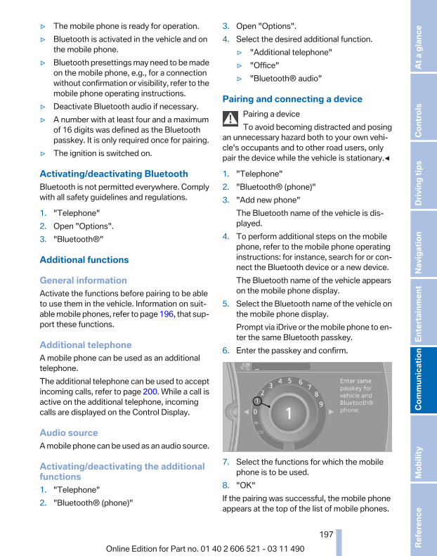
▷ The mobile phone is ready for operation.▷ Bluetooth is activated in the vehicle and on
the mobile phone.▷ Bluetooth presettings may need to be made
on the mobile phone, e.g., for a connectionwithout confirmation or visibility, refer to themobile phone operating instructions.
▷ Deactivate Bluetooth audio if necessary.▷ A number with at least four and a maximum
of 16 digits was defined as the Bluetoothpasskey. It is only required once for pairing.
▷ The ignition is switched on.
Activating/deactivating BluetoothBluetooth is not permitted everywhere. Complywith all safety guidelines and regulations.
1. "Telephone"2. Open "Options".3. "Bluetooth®"
Additional functions
General informationActivate the functions before pairing to be ableto use them in the vehicle. Information on suit‐able mobile phones, refer to page 196, that sup‐port these functions.
Additional telephoneA mobile phone can be used as an additionaltelephone.The additional telephone can be used to acceptincoming calls, refer to page 200. While a call isactive on the additional telephone, incomingcalls are displayed on the Control Display.
Audio sourceA mobile phone can be used as an audio source.
Activating/deactivating the additionalfunctions1. "Telephone"2. "Bluetooth® (phone)"
3. Open "Options".4. Select the desired additional function.
▷ "Additional telephone"▷ "Office"▷ "Bluetooth® audio"
Pairing and connecting a devicePairing a deviceTo avoid becoming distracted and posing
an unnecessary hazard both to your own vehi‐cle's occupants and to other road users, onlypair the device while the vehicle is stationary.◀
1. "Telephone"2. "Bluetooth® (phone)"3. "Add new phone"
The Bluetooth name of the vehicle is dis‐played.
4. To perform additional steps on the mobilephone, refer to the mobile phone operatinginstructions: for instance, search for or con‐nect the Bluetooth device or a new device.The Bluetooth name of the vehicle appearson the mobile phone display.
5. Select the Bluetooth name of the vehicle onthe mobile phone display.Prompt via iDrive or the mobile phone to en‐ter the same Bluetooth passkey.
6. Enter the passkey and confirm.
7. Select the functions for which the mobilephone is to be used.
8. "OK"If the pairing was successful, the mobile phoneappears at the top of the list of mobile phones.
Seite 197
197Online Edition for Part no. 01 40 2 606 521 - 03 11 490
Re
fere
nce
Mob
ility
Com
mun
icat
ion
Ente
rtain
men
tNa
vigat
ion
Drivi
ng ti
psCo
ntro
lsAt
a gl
ance
The functions supported by the mobile phoneand audio device are displayed as symbols whenpaired.White symbol: the function is active.Gray symbol: the function is inactive.
Symbol Function
Telephone.
Additional telephone.
Audio source.
Four devices can be paired with the vehicle atonce. Three devices can be connected with thevehicle at once.If pairing was unsuccessful: What to do if..., referto page 198.
Following the initial pairing▷ The mobile phone is detected/connected in
the vehicle within a short period of timewhen the engine is running or the ignition isswitched on.
▷ The phone book entries of the telephonestored on the SIM card* or mobile phone aretransmitted to the vehicle after detection,depending on the mobile phone.
▷ Four devices can be paired.▷ Specific settings may be necessary in some
mobile phones, e.g., authorization or a se‐cure connection; refer to the mobile phoneoperating instructions.
Connecting a specific deviceIf more than one device is detected by the vehi‐cle, the device at the top of the list is connected.A different device can be connected by select‐ing it.
1. "Telephone"2. "Bluetooth® (phone)"3. Select the device that is to be connected.The functions that were assigned to the devicebefore unpairing are assigned to the device
when it is reconnected. If the device is alreadyconnected, these functions are deactivated.
Configuring the devicesAdditional functions can be activated or deacti‐vated for paired and connected devices.
1. "Telephone"2. "Bluetooth® (phone)"3. Highlight the device to be configured.4. Open "Options".5. "Configure phone"6. At least one function must be selected.
▷ "Telephone"▷ "Additional telephone"▷ "Audio"
7. "OK"If a function is assigned to a device, the functionwill be deactivated where appropriate for a de‐vice that is already connected and the device willbe unpaired.
Swapping the telephone and additionaltelephoneThe function of the telephone and additional tel‐ephone can be swapped automatically.
1. "Telephone"2. "Bluetooth® (phone)"3. "Swap phone/addit. phone"
Unpairing a device1. "Telephone"2. "Bluetooth® (phone)"3. Highlight the device that is to be unpaired.4. Open "Options".5. "Remove phone from list"
What to do if...Information on suitable mobile phones, refer topage 196.The mobile phone could not be paired or con‐nected.
Seite 198
198Online Edition for Part no. 01 40 2 606 521 - 03 11 490
Tele
phon
e

▷ Is Bluetooth activated in the vehicle and onthe mobile phone? Activate Bluetooth in thevehicle and on the mobile phone.
▷ Do the Bluetooth passkeys on the mobilephone and the vehicle match? Enter thesame passkey on the mobile phone and viaiDrive.
▷ Did it take longer than 30 seconds to enterthe passkey? Repeat the pairing procedure.
▷ Are too many Bluetooth devices connectedto the mobile phone or vehicle? Delete con‐nections with other devices if necessary.
▷ Is the audio connection activated? Deacti‐vate the audio connection.
▷ Is the mobile phone in power-save mode ordoes it have only a limited remaining batterylife? Charge the mobile phone in the snap-in adapter* or via the charging cable.
▷ Depending on the mobile phone, it is possi‐ble that only one device can be connectedto the vehicle. Unpair the connected devicefrom the vehicle and pair and connect onlyone device.
▷ The mobile phone no longer reacts? Switchthe mobile phone off and on again. Repeatthe pairing procedure.
The telephone functions are not available.▷ Is the mobile phone paired as an additional
telephone and is the additional telephonefunction deactivated? Activate the function.
▷ Is an outgoing call not possible? Connectthe mobile phone as a telephone.
No or not all phone book entries are displayed,or they are incomplete.▷ Transmission of the phone book entries is
not yet complete.▷ It is possible that only the phone book en‐
tries of the mobile phone or the SIM card*are transmitted.
▷ It may not be possible to display phone bookentries with special characters.
▷ The number of phone book entries beingstored is too high.
▷ Is the data volume of the contact too large,e.g., due to stored information such asnotes? Reduce the data volume of the con‐tact.
▷ Is the mobile phone connected as an audiosource or additional telephone? The mobilephone must be connected as a telephone.
The phone connection quality is poor.▷ The strength of the Bluetooth signal on the
mobile phone can be adjusted, dependingon the mobile phone.
▷ Insert the mobile phone into the snap-inadapter* or place it in the area of the centerconsole.
▷ Adjust the volume of the microphone andloudspeakers separately.
If all points in this list have been checked and therequired function is still not available, pleasecontact the hotline or service center.
ControlsAdjusting the volumeTurn the knob until the desired volume is se‐lected. The setting is stored for the remote con‐trol currently in use.The vehicle automatically adjusts the volume ofthe microphone on the telephone and the vol‐ume of the called party. Depending on the mo‐bile phone, the volumes may need to be ad‐justed. The settings can only be created duringa call and must be adjusted separately for eachtelephone. The settings are deleted when thetelephone is unpaired.
1. "Settings"2. "Tone"3. "Volume settings"4. Select the desired setting: "Microphone" or
"Loudspeak."5. To adjust: turn the controller.6. To store: press the controller.
Seite 199
199Online Edition for Part no. 01 40 2 606 521 - 03 11 490
Re
fere
nce
Mob
ility
Com
mun
icat
ion
Ente
rtain
men
tNa
vigat
ion
Drivi
ng ti
psCo
ntro
lsAt
a gl
ance

Incoming call
Receiving callsIf the number of the caller is stored in the phonebook and is transmitted by the network, thename of the contact is displayed. Otherwise,only the phone number is displayed.If more than one phone number is assigned to acontact, only the name of the contact is dis‐played.For calls on the additional telephone, the num‐ber is only displayed if it is transmitted by thenetwork.An incoming call to the additional telephone isautomatically rejected if there is an active call onthe other telephone.
Accepting a call
Via iDrive "Accept"
Via the button on the steering wheelPress the button.
Via the instrument cluster*"Accept"
Rejecting a call
Via iDrive "Reject"
Via the instrument cluster*"Reject"
Ending a call
Via iDrive
"End call"
Via the button on the steering wheelPress the button.
Via the instrument cluster*"End call"
Entering a phone number
Dialing a number1. "Telephone"2. "Dial number"3. Select the digits individually.4. Select the symbol.
The phone number can also be entered by voice.
Calls with multiple participants
General informationYou can switch between calls or connect twocalls to a single conference call. These functions
Seite 200
200Online Edition for Part no. 01 40 2 606 521 - 03 11 490
Tele
phon
e

must be supported by the mobile phone andservice provider.
Accepting a call while speaking toanother partyThis function might have to be activated by theservice provider and the mobile phone must beadjusted accordingly.If a second call comes in during an ongoing call,a call waiting signal is sounded where appropri‐ate.
"Accept"The call is accepted and the existing call is puton hold.
Establishing a second callEstablish an additional call during an active call.
1. "Telephone"2. "Active calls"3. "Hold"
The existing call is put on hold.
4. Dial the new phone number or select it froma list.
"Return"The call on hold is resumed.
Switching between two calls, hold callThe active call is displayed in color.The call on hold is displayed in gray.
"Swap calls"The call on hold is resumed.
Establishing a conference callTwo calls can be connected to a single tele‐phone conference call.
1. Establish two calls.2. "Conference call"When terminating a conference call, both callsare ended. If one call is terminated by anotherparty, the other call can be continued.
Switching the microphone to muteWhen a call is active, the microphone can bemuted.
1. "Telephone"2. "Active calls"3. "Microphone mute"A microphone that has been switched to muteis automatically reactivated:▷ When a new connection is established.▷ When switching between call parties.
DTMF suffix dialingDTMF suffix dialing can be used for gaining ac‐cess to network services or for controlling devi‐ces, e.g., to make a remote inquiry of an answer‐ing machine. The DTMF code is needed for thispurpose.
1. "Telephone"2. Select the contact from a list or "Dial
number".3. "Keypad dialing"4. Enter the DTMF code via iDrive.
Phone book
DisplaysThe phone book accesses the contacts andshows all contacts for which a phone numberhas been stored. The entries can be selected tomake a call.
1. "Telephone"2. "Phone book"
Seite 201
201Online Edition for Part no. 01 40 2 606 521 - 03 11 490
Re
fere
nce
Mob
ility
Com
mun
icat
ion
Ente
rtain
men
tNa
vigat
ion
Drivi
ng ti
psCo
ntro
lsAt
a gl
ance

A symbol indicates the storage location of thecontacts.
Calling a contact
Symbol Meaning
Contact with one stored phone num‐ber.
Contact with more than one storedphone number.
Call not possible; mobile phone with‐out reception or network, or ServiceRequest* is active.
For contacts with one stored phone number: se‐lect the required contact. The connection is be‐ing established.For contacts with more than one stored phonenumber: select the required contact and thephone number. The connection is being estab‐lished.
Editing a contactChanging the entries in "Contacts". When acontact is changed, the changes are not storedon the mobile phone. A copy of the entry isstored in the vehicle.
1. Highlight the contact.2. Open "Options".3. "Edit entry"The contact can be edited.
Redialing
General informationThe list of dialed numbers in the mobile phoneis transmitted to the vehicle depending on themobile phone. The 20 phone numbers dialedlast are displayed. The sorting order of thephone numbers depends on the particular mo‐bile phone.
Dialing the number via the instrumentclusterThis is possible when there is no active call.
1. Press the button on the steeringwheel.
2. Select the desired phone number.The connection is established.
Dialing a number via iDrive1. "Telephone"2. "Redial"3. Select the desired entry and the phone num‐
ber if necessary.The connection is established.
Saving an entry in the contacts1. Highlight the entry.2. Open "Options".3. "Store as new contact" or "Add to existing
contact"4. Select "New phone number" or contact.5. Select the type of number: "Home",
"Business", "Mobile" or "Other"6. Complete the entries if necessary.7. If necessary, "Store contact in vehicle".
Received calls
Displaying callsThe 20 calls that were last received are dis‐played.
1. "Telephone"
Seite 202
202Online Edition for Part no. 01 40 2 606 521 - 03 11 490
Tele
phon
e

2. "Received calls"
Calling a number from the listSelecting an entry.The connection is established.
Saving an entry in the contacts1. Highlight the entry.2. Open "Options".3. "Store as new contact" or "Add to existing
contact"4. Select "New phone number" or contact.5. Select the type of number: "Home",
"Business", "Mobile" or "Other"6. Complete the entries if necessary.7. If necessary, "Store contact in vehicle".
Hands-free system
General informationCalls that are being made on the hands-freesystem can be continued on the mobile phoneand vice versa.
From the mobile phone to the hands-free systemCalls that were begun outside of the Bluetoothrange of the vehicle can be continued on thehands-free system with the ignition switchedon.Depending on the mobile phone, the system au‐tomatically switches to the hands-free system.If the system does not switch over automatically,follow the instructions on the mobile phone dis‐
play; refer also to the mobile phone operatinginstructions.
From the hands-free system to themobile phoneCalls that are made on the hands-free systemcan in some cases be continued on the mobilephone; this depends on the mobile phone.Follow the instructions on the mobile phone dis‐play; refer also to the mobile phone operatinginstructions.
Voice operation*Vehicles equipped with the voice activation sys‐tem: operation, refer to page 25.Vehicles not equipped with the voice activationsystem: depending on the equipment, the mo‐bile phone can be voice operated as describedbelow.The list of short commands in the operatingmanual does not apply to this type of voice op‐eration.
The concept▷ The mobile phone can be operated without
taking your hands from the steering wheel.▷ In many cases, the entries are accompanied
by announcements or questions.▷ ›...‹ Verbal instructions for voice operation.
Using voice activation
Activating the voice activation system
1. Briefly press the button on thesteering wheel.
2. Say the command.
Terminating the voice activationsystem
Briefly press the button on the steeringwheel or ›Cancel‹.
Seite 203
203Online Edition for Part no. 01 40 2 606 521 - 03 11 490
Re
fere
nce
Mob
ility
Com
mun
icat
ion
Ente
rtain
men
tNa
vigat
ion
Drivi
ng ti
psCo
ntro
lsAt
a gl
ance

Possible commands
Having possible commands read aloudPress the button. ›Help‹. Possible commandsare announced.The digits from zero to nine are recognized. Thedigits can be spoken separately or combined ina sequence to accelerate the entry.
Using alternative commandsThe system often recognizes a number of dif‐ferent commands to run a function; for instance:›Dial name‹ or ›Name‹
Example: dialing a phone number
1. Briefly press the button on thesteering wheel.
2. ›Dial number‹The system says: »Please say the number«
3. E.g., ›123 456 790‹The system says: »123 456 790. Continue?«
4. ›Dial‹The system says: »Dialing number«
Calling
Dialing a phone number1. ›Dial number‹2. Say the phone number.3. ›Dial‹
Correcting the phone numberThe sequence of digits can be deleted after thesystem has repeated the digits.›Correct number‹The command can be repeated as often as nec‐essary.
Deleting a phone number›Delete‹All digits entered up to that point are deleted.
Redialing›Redial‹
Voice phone book*Depending on how your vehicle is equipped, itmay be necessary to create your own voicephone book.The entries must be entered using voice activa‐tion and are separate from the memory in themobile phone. Up to 50 entries can be set up.
Saving an entry1. ›Save name‹2. Say the name. Do not exceed the speaking
duration of approx. 2 seconds.3. Say the phone number after being prompted
to do so by the system.4. ›Save‹
Deleting an entry1. ›Delete name‹2. Say the name after being prompted to do so.3. Confirm the query with ›Yes‹.
Deleting all entries1. ›Delete phonebook‹
The dialog for deleting the phone book isopened.
2. Confirm the query with ›Yes‹.3. Confirm the query again with ›Yes‹.
Reading and selecting entries1. ›Read phonebook‹
The dialog for reading the phone book isopened.
2. Say ›Dial number‹ when the desired entry isread.
Selecting an entry1. ›Dial name‹2. Say the name after being prompted to do so.3. Confirm the query with ›Yes‹.
Seite 204
204Online Edition for Part no. 01 40 2 606 521 - 03 11 490
Tele
phon
e

Adjusting the volumeTurn the knob during an announcement.▷ The volume remains constant even if the
volume of other audio sources is changed.▷ The volume is stored for the remote control
currently in use.
NotesDo not use the voice operation to initiate anEmergency Request. In stressful situations, thevoice and vocal pitch can change. This can un‐necessarily delay the establishment of a tele‐phone connection.Instead, use the SOS button*, refer topage 248, in the vicinity of the interior mirror.
Environmental conditions▷ Say the commands, numbers, and letters
smoothly and with normal volume, empha‐sis, and speed.
▷ Always say commands in the language ofthe system. The language for the mobilephone voice operation is preset and cannotbe changed in the Control Display.
▷ Keep the doors, windows, and convertibletop closed to prevent noise interference.
▷ Avoid making other noise in the vehiclewhile speaking.
Snap-in adapter*Installation positionIn the center armrest.
Inserting the snap-in adapter1. Press the button and remove the cover.
2. Insert the snap-in adapter at the front, ar‐row 1, and press down, arrow 2, until it en‐gages.
Inserting the mobile phone1. Depending on the mobile phone, remove
the protective cap from the antenna con‐nector of the mobile phone.
2. Slide the mobile phone with the buttons fac‐ing up in the direction of the electrical con‐nections, arrow 1, and push downward, ar‐row 2 until it engages.
Seite 205
205Online Edition for Part no. 01 40 2 606 521 - 03 11 490
Re
fere
nce
Mob
ility
Com
mun
icat
ion
Ente
rtain
men
tNa
vigat
ion
Drivi
ng ti
psCo
ntro
lsAt
a gl
ance

Removing the mobile phone
Press the button and remove the mobile phone.
Seite 206
206Online Edition for Part no. 01 40 2 606 521 - 03 11 490
Tele
phon
e

Office*At a glanceGeneral informationContacts, appointments, tasks, notes, text mes‐sages, and e-mails from the mobile phone canbe displayed on the Control Display if the mobilephone provides compatible support of thesefunctions and the necessary Bluetooth stand‐ards.Information about which mobile phones supportthe Office functions can be found atwww.bmwusa.com/bluetooth. A limited numberof compatible mobile phones is available for Of‐fice.Contents are only displayed in full length whenthe vehicle is stationary.The mobile phone has read-access only.
Do not use Office while drivingTo avoid becoming distracted and posing
an unnecessary hazard to your vehicle's occu‐pants and to other road users, never attempt touse the controls or enter information unless traf‐fic and road conditions allow this.◀
Requirements▷ A suitable mobile phone is paired with the
vehicle and connected. In some mobilephones, data access must be confirmed onthe mobile phone.
▷ The time, time zone, and date, refer topage 79, are correctly set on the ControlDisplay and on the mobile phone to correctlydisplay appointments, for example.
▷ Office is activated, refer to page 197.
UpdatingData are updated every time the mobile phoneis connected to the vehicle. Appointment en‐tries, tasks, notes and reminders can be updatedseparately.
1. "Office"2. "Current office", "Calendar", "Tasks",
"Notes" or "Reminders"3. Open "Options".4. "Update data"
Cell phone data are transmitted again to thevehicle.
Office informationThe number of unread messages and activetasks as well as the upcoming appointments aredisplayed.
1. "Office"2. "Current office"3. Select the desired entry to display details.
ContactsAt a glanceContacts can be created and edited. The con‐tacts from the mobile phone* are displayed aswell if this function is supported by the mobilephone. Addresses can be adopted as destina‐tions for navigation and the phone numbers canbe dialed.
Displaying contacts
General information1. "Office"
Seite 207
207Online Edition for Part no. 01 40 2 606 521 - 03 11 490
Re
fere
nce
Mob
ility
Com
mun
icat
ion
Ente
rtain
men
tNa
vigat
ion
Drivi
ng ti
psCo
ntro
lsAt
a gl
ance

2. "Contacts"
All contacts are listed in alphabetical order. De‐pending on the number of contacts, an A-Zsearch is offered, refer to page 24.A symbol indicates the storage location of thecontacts:
Symbol Storage location
No symbol In the vehicle; the address has notbeen checked as a destination.
In the vehicle; the address hasbeen checked as a destination.
Mobile phone.
Dialing phone numbers*1. Select the desired contact.2. Select the phone number.
The connection is established.
Editing a contact1. Select the desired contact.2. "Edit contact"
3. Change the entries.4. "Store contact in vehicle"
When a contact is edited, the changes are notstored on the mobile phone. A copy of the entryis stored in the vehicle.
Selecting the contact as a navigationdestination*1. Select the desired contact.2. Select the address.
When contacts from the mobile phone areused, the address may need to be matchedto the navigation data contained in the vehi‐cle. In this case:Correct the address.
3. "Start guidance" or "Add as anotherdestination"
Checking the address as a destination*An address that is to be used for destinationguidance must match the navigation data con‐tained in the vehicle. The address can bechecked for this purpose.
1. Select the desired contact and highlight theaddress.
2. Open "Options".3. "Check as destination"4. Correct and store the address if necessary.If the address is corrected and stored, a copy ofit is stored in the vehicle. The address is notchanged on the mobile phone.
New contact
General informationA contact can have up to 8 phone numbers,2 addresses, 3 e-mail addresses and one Inter‐net address.
1. "Office"2. "Contacts"3. Open "Options".
Seite 208
208Online Edition for Part no. 01 40 2 606 521 - 03 11 490
Offic
e

4. "New contact"
5. The entry fields are still filled with the previ‐ous entries: "Delete input fields"
6. Fill in the entry fields: select the symbol nextto the entry field.
7. Enter the text and assign the contact type.8. If the vehicle is equipped with a navigation
system: Enter the address. Only addressescontained in the navigation data in the vehi‐cle can be entered. This ensures that desti‐nation guidance is possible for all ad‐dresses.If necessary, "Accept address".
9. "Store contact in vehicle"
Contact typesVarious contact types can be assigned to phonenumbers and addresses.
Symbol Meaning
Home phone number.
Business phone number.
Mobile phone number.
Other phone number.
Home address.
Business address.
Specifying the home addressA home address can be stored. It appears at thetop of the contact list.
1. "Home"2. Create a contact.
3. "Store contact in vehicle"
Selecting the sorting order of thenames*Names can be displayed in a different order.
1. "Office"2. "Contacts"3. Open "Options".4. "Display: last, first name" or "Display: first,
last name"Depending on how the contacts were stored onthe mobile phone, the sorting order of the namesmay differ from the selected sorting order.
Show contact picturesPictures stored with the contacts are stored inthe vehicle when the mobile phone is connectedto the vehicle. The number of transmitted pic‐tures depends on the mobile phone. The mobilephone must support this function.
1. "Office"2. "Contacts"3. Open "Options".4. "Show images"Display of all contact pictures is activated or de‐activated.
Exporting/importing contactsContacts can be exported and imported via thePersonal Profile, refer to page 33. The contactsstored in the vehicle are exported, but not thosefrom the mobile phone.
Deleting contactsOnly contacts that are stored in the vehicle aredeleted. The contacts on the mobile phone*cannot be deleted.
1. "Office"2. "Contacts"3. Highlight the contact.4. Open "Options".
Seite 209
209Online Edition for Part no. 01 40 2 606 521 - 03 11 490
Re
fere
nce
Mob
ility
Com
mun
icat
ion
Ente
rtain
men
tNa
vigat
ion
Drivi
ng ti
psCo
ntro
lsAt
a gl
ance

5. "Delete contact"or "Delete all contacts".6. If necessary. "Yes"
MessagesGeneral informationWhether or not text messages and e-mails fromthe mobile phone are displayed depends onwhether transmission from the mobile phone tothe vehicle is supported. Text messages and e-mails may not be supported by the service pro‐vider, or the function may need to be enabledseparately. After the mobile phone is first paired,transmission may take several minutes. Mes‐sages are only displayed in full length when thevehicle is stationary. Messages from the addi‐tional telephone are not transmitted.Display of different messages:▷ Text messages.▷ My Info* messages from the BMW Assist
Portal.▷ Messages from the BMW Assist Concierge
service*.▷ Messages from BMW Info*.▷ E-mails from the mobile phone.
Displaying messages1. "Office"2. "Messages"A symbol identifies the type of message.
Symbol Message type
Text messages.
My Info
Message from the Concierge serv‐ice.
Message from BMW Info.
E-mail from mobile phone.
Filtering the message listThe message list can be filtered, when morethan one type of message exists.
1. "Filter:"
2. Select the type of message.▷ "All"
All messages are displayed.▷ "E-mail"
Only e-mails from the mobile phone aredisplayed.
▷ "Service message"Only messages from the BMW AssistConcierge service, My Info and BMWInfo are displayed.
▷ "Text message"Only text messages from the mobilephone are displayed.
Deleting messagesMessages from the Concierge service, My Info,and BMW Info can be deleted.Delete a message:
1. "Office"2. "Messages"3. Select the desired message.4. Open "Options".5. "Delete message"Delete all messages:
1. "Office"2. "Messages"
Seite 210
210Online Edition for Part no. 01 40 2 606 521 - 03 11 490
Offic
e

3. Open "Options".4. "Delete all messages" or "Delete service
messages"
Text messages
Calling the sender of a text message1. Select the desired message.2. Select the symbol.
Saving the sender in the contacts1. Highlight the desired message.2. Open "Options".3. "Store as new contact" or "Add to existing
contact"
Reading the text message out loud*Read the text messages out loud, refer topage 214.
My Info
Starting destination guidance1. Select the message.2. "Start guidance" or "Add as another
destination"
Dialing the number in the messageUp to 4 phone numbers can be transmitted witha message.
1. Select the desired message.2. "Call":
If the message contains a number, the con‐nection is established.
"Select phone number":If the message contains more than one num‐ber, select the desired number from the list.The connection is established.
Message from the Concierge service
Starting destination guidance1. Select the desired message.
2. "Start guidance" or "Add as anotherdestination"
3. Start destination guidance, if necessary.
Dialing the number in the messageUp to 4 phone numbers can be transmitted witha message.
1. Select the desired message.2. "Call":
If the message contains a number, the con‐nection is established.
"Select phone number":If the message contains more than one num‐ber, select the desired number from the list.The connection is established.
Storing an address1. Select the desired message.2. Open "Options".3. "Store contact in vehicle"
Displaying additional information1. Select the desired message.2. "Further information"
BMW Info
Starting destination guidance1. Select the desired message.2. "Start guidance" or "Add as another
destination"
Dialing the number in the messageUp to 4 phone numbers can be transmitted witha message.
Seite 211
211Online Edition for Part no. 01 40 2 606 521 - 03 11 490
Re
fere
nce
Mob
ility
Com
mun
icat
ion
Ente
rtain
men
tNa
vigat
ion
Drivi
ng ti
psCo
ntro
lsAt
a gl
ance

1. Select the desired message.2. "Call":
If the message contains a number, the con‐nection is established.
"Select phone number":If the message contains more than one num‐ber, select the desired number from the list.The connection is established.
E-mail*
Displaying e-mails1. "Office"2. "Messages"3. Select the desired e-mail.
Displaying e-mail contactsIf the sender and recipient of an e-mail are trans‐mitted by the mobile phone, this information isdisplayed in the e-mail.
"Sender/Recipient"If the e-mail addresses are stored in the con‐tacts, the contact is displayed. Select the con‐tact to display details.If the e-mail addresses are not stored in the con‐tacts, only the e-mail address is displayed.
Using contact dataContact data from appointments, e-mails andnotes can be saved or selected*, refer topage 214.
Deactivating the full displayWhen an e-mail is opened in the vehicle, the e-mail is fully transmitted to the vehicle. This mayresult in charges.
1. "Office"2. "Messages"3. Open "Options".4. "Fully download e-mails"
Only a part of the email from the cell phoneis loaded into the vehicle.
Reading the e-mail out loud*Read the e-mail out loud, refer to page 214.
CalendarDisplay the calendarAppointments during the last 20 and the next 50days can be displayed.
1. "Office"2. "Calendar"
The appointments on the current day aredisplayed.
Selecting the calendar day1. Select the date.
2. Select the desired day or date.▷ "Next day"▷ "Date:"▷ "Previous day"▷ "Today"
Display the appointment1. Select the desired appointment.2. Scroll through the appointment if neces‐
sary:▷ Turn the controller.▷ Select the symbol.
Using contact dataContact data from appointments, e-mails andnotes can be saved or selected*, refer topage 214.
Seite 212
212Online Edition for Part no. 01 40 2 606 521 - 03 11 490
Offic
e

Reading the appointment out loud*Read the appointment out loud, refer topage 214.
TasksDisplaying the task listDisplay tasks that are due within the next90 days.
1. "Office"2. "Tasks"
Sorting the task list1. Select the header in the task list.
2. Select the sorting criterion:▷ "Priority (!)"*▷ "Subject"▷ "Due date"
Displaying the task1. Select the desired task.2. Scroll in the task if necessary:
▷ Turn the controller.▷ Select the symbol.
Using contact dataContact data from appointments, e-mails andnotes can be saved or selected*, refer topage 214.
Reading the task out loud*Read the task out loud, refer to page 214.
NotesDisplaying notes1. "Office"2. "Notes"
All notes are displayed.
Displaying the note1. Select the desired note.
2. Scroll in the note if necessary:▷ Turn the controller.▷ Select the symbol.
Using contact dataContact data from appointments, e-mails andnotes can be saved or selected*, refer topage 214.
Reading the note out loud*Read the note out loud, refer to page 214.
RemindersDisplaying remindersReminders of pending appointments and tasksare displayed. After an appointment or after atask is due, the reminder is no longer displayed.
1. "Office"2. "Reminders"3. Select the desired reminder.The corresponding appointment or the task aredisplayed.
Seite 213
213Online Edition for Part no. 01 40 2 606 521 - 03 11 490
Re
fere
nce
Mob
ility
Com
mun
icat
ion
Ente
rtain
men
tNa
vigat
ion
Drivi
ng ti
psCo
ntro
lsAt
a gl
ance
Using contact dataAt a glanceContact data from calendar entries, appoint‐ments, tasks, emails and notes can be stored orselected*.
Displaying contact or selecting phonenumber1. "Use contact data"2. Display the contact or select the phone
number:▷ Select the contact to display contact de‐
tails.▷ Select the phone number to establish a
connection directly.
Storing contact data1. "Use contact data"2. Highlight the phone number or e-mail ad‐
dress.3. Open "Options".4. "Add to existing contact" or "Store as new
contact"
Reading out loud*Text messages, e-mails, appointment entries,tasks, and notes can be read out loud.
1. Select the desired message, appointment,task, or note.
2. Select the symbol.The following options are available during read‐ing:▷ "Pause"
Interrupt reading. Select again to restartreading.
▷ "Back to beginning"Start reading message again from the be‐ginning.
▷ Select the symbol.Skip a paragraph.
▷ Select the symbol.Go back one paragraph.
▷ To end reading, tilt the controller to the left.
What to do if...Information on suitable mobile phones, refer topage 196.Appointments, tasks, notes, text messages, ore-mails from the mobile phone are not dis‐played.▷ The mobile phone is not capable of the
missing function or is not connected cor‐rectly.
▷ The Office function is deactivated.▷ The mobile phone is connected as an addi‐
tional phone.▷ Appointments are older than 20 days or are
more than 50 days in the future.▷ The tasks have been marked as completed
or have a due date that lies more than90 days in the future.
▷ Depending on the number of stored ap‐pointments, task notes, and messages inthe mobile phone, not all are displayed in thevehicle.
Not all appointments and tasks from the mobilephone are displayed at the right time?▷ The time zone, time or date is incorrectly set
on the Control Display and mobile phone.The e-mail attachment is not displayed.▷ E-mails are transmitted without an attach‐
ment.Entries are not displayed in full length.▷ Text were already transmitted from the mo‐
bile phone in a shortened form.▷ Synchronization between the mobile phone
and vehicle may take several minutes.The contact pictures are not being displayed?▷ A max. of 200 contact pictures can be stored
in the vehicle.The E-mail is displayed with a delay?
Seite 214
214Online Edition for Part no. 01 40 2 606 521 - 03 11 490
Offic
e

▷ Check the e-mail settings on the telephoneand adjust if necessary.
If all points in this list have been checked and therequired function is still not available, pleasecontact the hotline or service center.
Seite 215
215Online Edition for Part no. 01 40 2 606 521 - 03 11 490
Re
fere
nce
Mob
ility
Com
mun
icat
ion
Ente
rtain
men
tNa
vigat
ion
Drivi
ng ti
psCo
ntro
lsAt
a gl
ance

Contacts*General informationContacts can be created and edited and the ad‐dresses can be adopted as destinations for nav‐igation.
New contact1. "Contacts"2. "New contact"
3. The entry fields are still filled with the previ‐ous entries: "Delete input fields"
4. Fill in the entry fields: select the symbol nextto the entry field.
5. Enter the text, refer to page 24.6. If the vehicle is equipped with a navigation
system: Enter the address. Only addressescontained in the navigation data in the vehi‐cle can be entered. This ensures that desti‐nation guidance is possible for all ad‐dresses.
7. If necessary, "Store".8. "Store contact in vehicle"
Specifying the home addressA home address can be stored. It appears at thetop of the contact list.
1. "Home"2. Create a contact.3. "Store contact in vehicle"
My contactsGeneral informationList of all contacts stored in the vehicle.
Displaying contacts1. "Contacts"2. "My contacts"
All contacts are listed in alphabetical order. De‐pending on the number of contacts, an A-Zsearch is offered, refer to page 24.A symbol indicates the storage location of thecontacts:
Symbol Storage location
No sym‐bol
In the vehicle; the address has notbeen checked as a destination.
In the vehicle; the address hasbeen checked as a destination*.
Seite 216
216Online Edition for Part no. 01 40 2 606 521 - 03 11 490
Cont
acts

Editing a contact1. Select the desired contact.2. "Edit contact"
3. Change the entries.4. Move the controller to the left.5. "Yes"
Selecting the contact as a navigationdestination*1. Select the desired contact.2. Select the address.3. "Start guidance" or "Add as another
destination"
Checking the address as a destination*An address that is to be used for destinationguidance must match the navigation data con‐tained in the vehicle. The address can bechecked for this purpose.
1. Select the desired contact and highlight theaddress.
2. Open "Options".3. "Check as destination"4. Correct and store the address if necessary.
Selecting the sorting order of thenamesNames can be displayed in a different order.
1. "My contacts"2. Highlight the contact.3. Open "Options".4. "Display: last, first name" or "Display: first,
last name"
Exporting/importing contactsContacts can be exported and imported via thePersonal Profile, refer to page 33.
Deleting contacts1. "My contacts"2. Highlight the contact.3. Open "Options".4. "Delete contact" or "Delete all contacts"
Seite 217
217Online Edition for Part no. 01 40 2 606 521 - 03 11 490
Re
fere
nce
Mob
ility
Com
mun
icat
ion
Ente
rtain
men
tNa
vigat
ion
Drivi
ng ti
psCo
ntro
lsAt
a gl
ance

BMW ConnectedDriveBMW Assist*General informationBMW Assist provides you with certain services,e.g., transmission of the position data of yourvehicle to the BMW Assist Response Center ifan Emergency Request* has been initiated.Many BMW Assist services depend on the indi‐vidually agreed upon contract.After your contract has expired, the BMW Assistsystem will be deactivated by the BMW AssistResponse Center without your having to visit aservice center. After the BMW Assist systemhas been deactivated, no BMW Assist serviceswill be available. The BMW Assist system can bereactivated by a service center after you sign anew contract.
Requirements▷ The installed BMW Assist system is logged
in to a wireless communications network.This network must be capable of transmit‐ting the services.
▷ To transmit position data, the vehicle mustbe able to determine the current position.
▷ The BMW Assist service contract wassigned with your service center or with theBMW Assist Response Center. Enablingmust have been completed.
▷ BMW Assist is activated.
Services offered▷ Emergency Request: when you press the
SOS button, a connection to the BMW As‐sist Response Center is established. TheBMW Assist Response Center then speakswith you and takes further steps to help you.
▷ Automatic Collision Notification: under cer‐tain conditions, a connection is establishedto the BMW Assist Response Center after aserious accident. If possible, the BMW As‐
sist Response Center then speaks with youand takes further steps to help you.
▷ Enhanced Roadside Assistance: BMWRoadside Assistance* can be contacted ifassistance is needed in the event of a break‐down. If possible, the vehicle and positiondata are transmitted in the process.
▷ Customer Relations: connection with Cus‐tomer Relations for information on all as‐pects of your vehicle.
▷ TeleService: data on your vehicle's servicestatus or required inspections are transmit‐ted to your service center, either automati‐cally before a service due date or when yourequest a BMW service appointment.
▷ Remote Door Unlock: the BMW Assist Re‐sponse Center provides assistance if, for ex‐ample, the remote control is not availableand the vehicle needs to be opened.
▷ Stolen Vehicle Recovery: after you reportthat your vehicle was stolen to the police, theBMW Assist Response Center can deter‐mine its position.
▷ In addition to these services, the optionalConvenience Plan offers Concierge serviceand information for route planning, traffic,and weather. A limited number of calls canbe made via the BMW Assist ResponseCenter with Critical Calling if, for example,the mobile phone is not available or dis‐charged.Press the SOS button to contact the BMWAssist Response Center.
BMW TeleService*General informationTeleService supports communication with yourservice center.▷ Data on the vehicle's service requirements
can be sent directly to the service center. Inthis way, the service center can plan its work
Seite 218
218Online Edition for Part no. 01 40 2 606 521 - 03 11 490
BMW
Con
nect
edDr
ive

in advance. This shortens the duration of theservice appointment.
▷ In the event of a breakdown, data on the ve‐hicle's condition can be sent directly toRoadside Assistance.
▷ The service varies by country.▷ Connection costs may ensue.▷ Services may be restricted abroad.
Requirements▷ BMW Assist is activated.▷ Wireless reception is available.▷ The engine is running.
Use of BMW TeleService*The TeleServices are typically activated in thevehicle.Even TeleService Customer Service is not ac‐tive, a voice contact to Roadside Assistance isstill possible.To continue using or to deactivate the services,please contact your service partner or the BMWcustomer hotline.
Concierge service*General informationThe BMW Assist Concierge service offers infor‐mation on events, gas stations or hotels, andprovides phone numbers and addresses. Hotelscan be booked directly by the BMW Assist Con‐cierge service. The Concierge service is part ofthe optional BMW Convenience Plan.
Starting the Concierge service1. "ConnectedDrive"
2. "Concierge"
3. "Start service"A voice connection is established with the BMWAssist Concierge service. Phone numbers andaddresses can be transmitted to the vehicle.
Roadside AssistanceAt a glanceBMW Roadside Assistance* can be contacted ifassistance is needed in the event of a break‐down.Roadside Assistance* can also be contacted viaa Check Control message, refer to page 82.
Starting Roadside Assistance
Vehicles not equipped with BMWAssist or BMW TeleService1. "ConnectedDrive"2. "Roadside Assistance"
The Roadside Assistance number is dis‐played. If the mobile phone* is paired, a con‐nection is established to Roadside Assis‐tance.
Seite 219
219Online Edition for Part no. 01 40 2 606 521 - 03 11 490
Re
fere
nce
Mob
ility
Com
mun
icat
ion
Ente
rtain
men
tNa
vigat
ion
Drivi
ng ti
psCo
ntro
lsAt
a gl
ance

Vehicles equipped with BMW Assist orBMW TeleService1. "ConnectedDrive"2. "Roadside Assistance"3. "Start service"
TeleService Diagnosis*TeleService Diagnosis enables the wirelesstransmission of detailed vehicle data that areimportant for vehicle diagnosis. These data aretransmitted automatically.After the data are transmitted, the voice con‐nection to Roadside Assistance is re-estab‐lished.
TeleService Help*TeleService Help enables an in-depth diagnosisof the vehicle by Roadside Assistance via wire‐less transmission.TeleService Help can be started after a promptby Roadside Assistance and the termination ofthe voice connection.
Starting TeleService Help1. Park the vehicle in a safe place.2. Set the parking brake.3. The engine is running.4. "TeleService Help"After completion of TeleService Help, a voiceconnection is established to Roadside Assis‐tance.
BMW Online*At a glanceA business search can be opened via BMW On‐line.License conditionsThis product contains NetFront Browser soft‐ware of ACCESS Co., Ltd. Copyright © 2007ACCESS Co., Ltd. All rights reserved.NetFront is a trademark or registered trademarkof ACCESS CO., LTD., in Japan and other coun‐tries.This software is based in part on the work of theIndependent JPEG Group.
Requirements▷ Subscription to the optional Convenience
Plan.▷ The date setting, refer to page 80, on the
Control Display is current.▷ The vehicle is located within wireless net‐
work coverage.
Starting BMW Online1. "ConnectedDrive"2. "BMW Online"
3. If necessary, "OK".The BMW Online home page is displayed.
Operating BMW OnlineTo start a search:▷ Turn the controller to highlight an element.▷ Press the controller to display an element.
Seite 220
220Online Edition for Part no. 01 40 2 606 521 - 03 11 490
BMW
Con
nect
edDr
ive

Opening the start page1. Open "Options".2. "Display start page"
Loading a new page1. Open "Options".2. "Reload"
Cancel1. Open "Options".2. "Cancel loading"
Customer RelationsAt a glanceContact Customer Relations for information onall aspects of your vehicle.
Calling Customer Relations
Vehicles not equipped with BMWAssist or BMW TeleService1. "ConnectedDrive"2. "Customer Relations"The Customer Relations phone number is dis‐played. If the mobile phone* is paired, a con‐nection is established to Customer Relations.
Vehicles equipped with BMW Assist orBMW TeleService1. "ConnectedDrive"2. "Customer Relations"3. "Start service"
Service Request*At a glanceSends information to your service partner to re‐quest the arrangement of a service appoint‐ment. The TeleService data is transmitted dur‐ing a Service Request. If possible, your servicepartner will establish contact with you.
Starting a Service Request1. "ConnectedDrive"2. "Service Request"3. "Start service"
A Service Request can be started via a CheckControl message, refer to page 82.
Seite 221
221Online Edition for Part no. 01 40 2 606 521 - 03 11 490
Re
fere
nce
Mob
ility
Com
mun
icat
ion
Ente
rtain
men
tNa
vigat
ion
Drivi
ng ti
psCo
ntro
lsAt
a gl
ance

Automatic Service Request*The TeleService data necessary for servicingthe vehicle are automatically sent to your servicepartner prior to the service deadline. If possible,the service partner will contact you and a serviceappointment can be arranged.To check when your service partner was noti‐fied:
1. "Vehicle Info"2. "Vehicle status"
3. Open "Options".4. "Last Service Request"
Services status*General informationCheck services status.
Displaying available servicesDisplay of all services available in the vehicle.
1. "ConnectedDrive"2. "Service Status"
3. "Available services"
Updating BMW AssistManual update of TeleService* and BMW As‐sist*."Update BMW Assist"
Data transfer*During the updating of BMW services, displaythe status of the data transfer.
1. "ConnectedDrive"2. Open "Options".3. "Data transfer"
Apps*At a glanceCertain software applications of a suitable cellphone can be integrated in the vehicle. Thesesoftware applications are displayed on the Con‐trol Display.They are operated via iDrive.
Requirements▷ The mobile phone is suitable.▷ The cell phone operating system supports
the software applications of Apps.▷ Software applications are installed on the
cell phone and ready to use.▷ Corresponding mobile wireless contract.
Any additionally incurred costs are not a partof Apps.
Seite 222
222Online Edition for Part no. 01 40 2 606 521 - 03 11 490
BMW
Con
nect
edDr
ive

▷ Use only BMW approved software applica‐tions; otherwise, it may result in malfunc‐tions.
Information about suitable cell phones, availablesoftware applications and their installation canbe found at www.bmw.com/connectivity or atthe service center.
Create the entries.Make entries only when traffic and road
conditions allow. Otherwise, the vehicle occu‐pants and other road users may be put in dangerbecause of the distraction from driving.For reasons of safety, some software applica‐tions are usable only while the vehicle is station‐ary.◀
Operate Apps1. Connect the cell phone via the snap-in
adapter or via the USB audio interface.2. "ConnectedDrive"3. Select the desired software application.
Displaying statusInformation about the currently available soft‐ware applications can be displayed.
1. "ConnectedDrive"2. "BMW apps"
PlugIn*Selected functions of the cell phone are dis‐played on the Control Display. They can be op‐erated via iDrive.
1. Connect cell phone via the snap-in adapter.2. "ConnectedDrive"3. "PlugIn"4. "Activate PlugIn"5. Navigate to the displayed functions via the
controller and select, for example, a desiredcategory or track.
Press button to switch within the cellphone functions to a higher level or back.
Press button twice to switch back to themain menu.
Notes▷ The ranges of Apps that can be displayed on
the Control Display depend on the range ofinstalled software applications on the cellphone.
▷ The data transmission of the software ap‐plications from the cell phone to the vehiclecan last some time. Some software applica‐tions depend on the speed of the availableInternet connection of the cell phone.
▷ Some cell phones cannot simultaneouslyuse Apps and the Bluetooth hands-free sys‐tem.If necessary, restart the software applicationon the cell phone after a phone conversa‐tion.
TeleService Report*Transmits technical data that is evaluated for theongoing development of BMW products fromyour vehicle to BMW in regular intervals if nec‐essary.TeleService Report is activated in vehicles thatmeet certain technical requirements and have avalid Assist contract; this feature is free ofcharge.Neither personal data nor position data is trans‐mitted.Indicate when the last Teleservice Report wastransmitted:
1. "Vehicle Info"2. "Vehicle status"3. Open "Options".4. "Last Teleservice Info"
Seite 223
223Online Edition for Part no. 01 40 2 606 521 - 03 11 490
Re
fere
nce
Mob
ility
Com
mun
icat
ion
Ente
rtain
men
tNa
vigat
ion
Drivi
ng ti
psCo
ntro
lsAt
a gl
ance
Online Edition for Part no. 01 40 2 606 521 - 03 11 490

MobilityTo ensure that you remain mobile at all times, this
chapter supplies you with important informationon the topics of fuels and lubricants, wheels and
tires, service, maintenance, and RoadsideAssistance.
Online Edition for Part no. 01 40 2 606 521 - 03 11 490

RefuelingFuel capOpening1. Briefly press the rear edge of the fuel filler
flap.
2. Turn the fuel cap counterclockwise.
3. Place the fuel cap in the bracket attached tothe fuel filler flap.
Closing1. Fit the cap and turn it clockwise until you
clearly hear a click.2. Close the fuel filler flap.
Do not pinch the retaining strapDo not pinch the retaining strap attached
to the cap; otherwise, the cap cannot be closedproperly and fuel vapors can escape.A message is displayed if the cap is loose ormissing.◀
Manually unlocking fuel filler flapIn the event of an electrical malfunction, for ex‐ample.1. Open the cover on the right side trim.
2. Pull the green knob with the fuel pump sym‐bol. This releases the fuel filler flap.
Observe the following whenrefuelingThe fuel tank is full when the filler nozzle clicksoff the first time.
Handling fuelsObey safety regulations posted at the gas
station.◀
Seite 226
226Online Edition for Part no. 01 40 2 606 521 - 03 11 490
Refu
elin
g
Fuel tank capacityFuel tank capacity: approx. 18.5 US gal/70 liters.
Refuel promptlyRefuel below a range of 30 miles/50 km;
otherwise, engine functions are not ensured anddamage may occur.◀
Seite 227
227Online Edition for Part no. 01 40 2 606 521 - 03 11 490
Re
fere
nce
Mob
ility
Com
mun
icat
ion
Ente
rtain
men
tNa
vigat
ion
Drivi
ng ti
psCo
ntro
lsAt
a gl
ance

FuelFuel quality
Refuel with unleaded fuel onlyDo not use leaded fuel as this would per‐
manently damage the catalytic converter.◀
Do not refuel with ethanolDo not refuel with E85, i.e., fuel with an
ethanol content of 85 %, or with Flex Fuel, as thiswould damage the engine and fuel supply sys‐tem.◀
Required fuel
Super Premium Gasoline/AKI 91 or AKI89BMW recommends AKI 91 or 89.
Gasoline with lower AKIThe minimum AKI Rating is 89.If you use gasoline with this minimum AKI Rat‐ing, the engine may produce knocking soundswhen starting at high outside temperatures.This has no effect on the engine life.
Minimum fuel gradeDo not use any gasoline below the mini‐
mum specified fuel grade; otherwise, enginedamage may occur.◀
Use high-quality brandsField experience has indicated significant differ‐ences in fuel quality: volatility, composition, ad‐ditives, etc., among gasolines offered for sale inthe United States and Canada.Fuels containing up to and including 10 % etha‐nol or other oxygenates with up to 2.8 % oxygenby weight, that is, 15 % MTBE or 3 % methanolplus an equivalent amount of co-solvent, will notvoid the applicable warranties with respect todefects in materials or workmanship.
Minimum fuel gradeThe use of poor-quality fuels may result in
driveability, starting and stalling problems es‐pecially under certain environmental conditionssuch as high ambient temperature and high al‐titude.Should you encounter driveability problemswhich you suspect could be related to the fuelyou are using, we recommend that you respondby switching to a recognized high-quality brandsuch as gasoline that is advertised as Top TierDetergent Gasoline.Failure to comply with these recommendationsmay result in unscheduled maintenance.◀
Seite 228
228Online Edition for Part no. 01 40 2 606 521 - 03 11 490
Fuel

Wheels and tiresTire inflation pressureSafety informationThe tire characteristics and tire inflation pres‐sure influence the following:▷ The service life of the tires.▷ Road safety.▷ Driving comfort.
Checking the pressureOnly check the tire inflation pressure when thetires are cold. This means after driving no morethan 1.25 miles/2 km or when the vehicle hasbeen parked for at least 2 hours. When the tiresare warm, the tire inflation pressure is higher.
Check the tire inflation pressure regularlyRegularly check the tire inflation pressure
and correct it as needed: at least twice a monthand before a long trip. If you fail to observe thisprecaution, you may be driving on tires with in‐correct tire pressures, a condition that may notonly compromise your vehicle's driving stability,but also lead to tire damage and the risk of anaccident.◀
After correcting the tire inflation pressure, rein‐itialize the Flat Tire Monitor.After correcting the tire inflation pressure, rein‐itialize the Tire Pressure Monitor.
Pressure specificationsThe tire inflation pressure table, refer topage 230, contains all pressure specificationsfor the specified tire sizes at the ambient tem‐perature. Pressure specifications apply to ap‐proved tire sizes and recommended tire brands.This information can be obtained from yourservice center.To identify the correct tire inflation pressure,please note the following:▷ Tire sizes of your vehicle.▷ Vehicle load.
▷ Maximum allowable driving speed.
Tire inflation pressures up to 100 mph/160 km/hFor speeds of up to 100 mph/160 km/h and foroptimum driving comfort, note the pressure val‐ues in the tire inflation pressure table, refer topage 230, and adjust as necessary.
These pressure values can also be found on thetire inflation pressure label on the driver's doorpillar.
Maximum permissible speedDo not exceed 100 mph/160 km/h; other‐
wise, tire damage and accidents may result.◀
Seite 229
229Online Edition for Part no. 01 40 2 606 521 - 03 11 490
Re
fere
nce
Mob
ility
Com
mun
icat
ion
Ente
rtain
men
tNa
vigat
ion
Drivi
ng ti
psCo
ntro
lsAt
a gl
ance

Tire inflation pressure values up to100 mph/160 km/h
650i
Tire size Pressure specifica‐tions in bar/PSI
Specifications in psi/kilopascal with coldtires
245/45 R 18 100 V M+S XL A/S245/40 R 19 98 V M+S XL A/S245/45 R 18 96 Y245/45 R 18 100 V M+S XL
2.3 / 33 2.6 / 38
F: 245/45 R 18 96 YR: 275/40 R 18 99 Y
2.3 / 33-
-2.4 / 35
F: 245/40 R 19 94 YR: 275/35 R 19 96 Y
2.4 / 35-
-2.6 / 38
F: 245/35 R 20 95Y XLR: 275/30 R 20 97Y XL
2.6 / 38-
-2.9 /42
Tire inflation pressures at max. speedsabove 100 mph/160 km/h
Speeds above 100 mph/160 km/hIn order to drive at maximum speeds in ex‐
cess of 100 mph/160 km/h, please observe, and,if necessary, adjust tire pressures for speedsexceeding 100 mph/160 km/h from the relevanttable on the following pages. Otherwise tiredamage and accidents could occur.◀
Tire inflation pressure values over100 mph/160 km/h
650iWithout high-speed tuning feature
Tire size Pressure specificationsin bar/PSI
Specifications inbar/PSI with coldtires
245/45 R 18 100 V M+S XL A/S245/45 R 18 96 Y245/45 R 18 100 V M+S XL
2.3 / 33 2.8 / 41
245/40 R 19 98 V M+S XL A/S
2,5 / 363 3.0 / 44
F: 245/45 R 18 96 YR: 275/40 R 18 99 Y
2.3 / 33-
-2.4 / 35
F: 245/40 R 19 94 YR: 275/35 R 19 96 Y
2.4 / 35-
-2.6 / 38
F: 245/35 R 20 95Y XLR: 275/30 R 20 97Y XL
2.6 / 38-
-2.9 /42
With high-speed tuning feature
Tire size Pressure specificationsin bar/PSI
Specifications inbar/PSI with coldtires
245/45 R 18 96 Y 2,5 / 363 3.0 / 44
245/45 R 18 100V M+S XL
2.7 / 39 3.2 / 46
F: 245/45 R 18 96 YR: 275/40 R 18 99 Y
2,5 / 363-
-2.7 / 39
Seite 230
230Online Edition for Part no. 01 40 2 606 521 - 03 11 490
Whe
els a
nd ti
res

Tire size Pressure specificationsin bar/PSI
F: 245/40 R 19 94 YR: 275/35 R 19 96 Y
2.6 / 38-
-3.0 / 44
F: 245/35 R 20 95Y XLR: 275/30 R 20 97Y XL
2.8 / 41-
-3,3 / 48
Tire identification marksTire size255/50 R 19 103 Y255: nominal width in mm50: aspect ratio in %R: radial tire code19: rim diameter in inches103: load rating, not for ZR tiresY: speed rating, before the R on ZR tires
Speed letterT = up to 118 mph, 190 km/hH = up to 131 mph, 210 km/hV = up to 150 mph, 240 km/hW = up to 167 mph, 270 km/hY = up to 186 mph, 300 km/h
Tire Identification NumberDOT code: DOT xxxx xxx 3510xxxx: manufacturer code for the tire brandxxx: tire size and tire design3510: tire ageTires with DOT codes meet the guidelines of theU.S. Department of Transportation.
Tire ageDOT … 3510: the tire was manufactured in the35th week in 2010.
RecommendationRegardless of wear, replace tires at least every6 years.
Uniform Tire Quality GradingQuality grades can be found where applicableon the tire sidewall between tread shoulder andmaximum section width.For example: Treadwear 200; Traction AA;Temperature A
DOT Quality GradesTreadwearTraction AA A B CTemperature A B CAll passenger car tires must conform to FederalSafety Requirements in addition to thesegrades.
TreadwearThe treadwear grade is a comparative ratingbased on the wear rate of the tire when testedunder controlled conditions on a specified gov‐ernment test course. For example, a tire graded150 would wear one and one-half, 1 g, times aswell on the government course as a tire graded100. The relative performance of tires dependsupon the actual conditions of their use, however,and may depart significantly from the norm dueto variations in driving habits, service practicesand differences in road characteristics and cli‐mate.
TractionThe traction grades, from highest to lowest, areAA, A, B, and C.Those grades represent the tire's ability to stopon wet pavement as measured under controlledconditions on specified government test surfa‐ces of asphalt and concrete. A tire marked C mayhave poor traction performance.The traction grade assigned to this tire is basedon straight-ahead braking traction tests, anddoes not include acceleration, cornering, hydro‐planing, or peak traction characteristics.
Seite 231
231Online Edition for Part no. 01 40 2 606 521 - 03 11 490
Re
fere
nce
Mob
ility
Com
mun
icat
ion
Ente
rtain
men
tNa
vigat
ion
Drivi
ng ti
psCo
ntro
lsAt
a gl
ance

TemperatureThe temperature grades are A, the highest, B,and C, representing the tire's resistance to thegeneration of heat and its ability to dissipateheat when tested under controlled conditionson a specified indoor laboratory test wheel. Sus‐tained high temperature can cause the materialof the tire to degenerate and reduce tire life, andexcessive temperature can lead to sudden tirefailure. The grade C corresponds to a level ofperformance which all passenger car tires mustmeet under the Federal Motor Vehicle SafetyStandard No. 109. Grades Band A representhigher levels of performance on the laboratorytest wheel than the minimum required by law.
Temperature grade for this tireThe temperature grade for this tire is es‐
tablished for a tire that is properly inflated andnot overloaded. Excessive speed, underinfla‐tion, or excessive loading, either separately or incombination, can cause heat buildup and pos‐sible tire failure.If necessary, have the vehicle towed.◀
RSC – Run-flat tiresRun-flat tires, refer to page 234, are labeled witha circular symbol containing the letters RSCmarked on the sidewall.
M+SWinter and all-season tires with better coldweather performance than summer tires.
Tire treadSummer tiresDo not drive with a tire tread depth of less than0.12 in/3 mm.There is an increased danger of hydroplaning ifthe tread depth is less than 0.12 in/3 mm.
Winter tiresDo not drive with a tire tread depth of less than0.16 in/4 mm.
Below a tread depth of 0.16 in/4 mm, tires areless suitable for winter operation.
Minimum tread depth
Wear indicators are distributed around the tire'scircumference and have the legally requiredminimum height of 0.063 in/1.6 mm.
They are marked on the side of the tire with TWI,Tread Wear Indicator.
Tire damageGeneral informationInspect your tires often for damage, foreign ob‐jects lodged in the tread, and tread wear.
NotesIndications of tire damage or other vehicle de‐fects:▷ Unusual vibrations during driving.▷ Unusual handling such as a strong tendency
to pull to the left or right.In case of tire damageIf there are indications of tire damage, re‐
duce your speed immediately and have thewheels and tires checked right away; otherwise,there is the increased risk of an accident.Drive carefully to the next service center or tireshop.If necessary, have the vehicle towed.◀
Repair of tire damageFor safety reasons, the manufacturer of
your vehicle recommends that you do not havedamaged tires repaired; they should be re‐
Seite 232
232Online Edition for Part no. 01 40 2 606 521 - 03 11 490
Whe
els a
nd ti
res
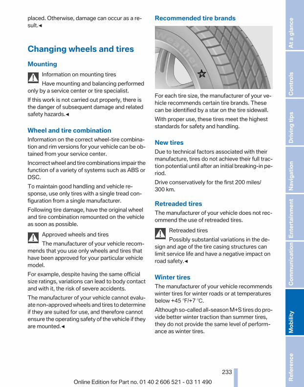
placed. Otherwise, damage can occur as a re‐sult.◀
Changing wheels and tiresMounting
Information on mounting tiresHave mounting and balancing performed
only by a service center or tire specialist.If this work is not carried out properly, there isthe danger of subsequent damage and relatedsafety hazards.◀
Wheel and tire combinationInformation on the correct wheel-tire combina‐tion and rim versions for your vehicle can be ob‐tained from your service center.Incorrect wheel and tire combinations impair thefunction of a variety of systems such as ABS orDSC.To maintain good handling and vehicle re‐sponse, use only tires with a single tread con‐figuration from a single manufacturer.Following tire damage, have the original wheeland tire combination remounted on the vehicleas soon as possible.
Approved wheels and tiresThe manufacturer of your vehicle recom‐
mends that you use only wheels and tires thathave been approved for your particular vehiclemodel.For example, despite having the same officialsize ratings, variations can lead to body contactand with it, the risk of severe accidents.The manufacturer of your vehicle cannot evalu‐ate non-approved wheels and tires to determineif they are suited for use, and therefore cannotensure the operating safety of the vehicle if theyare mounted.◀
Recommended tire brands
For each tire size, the manufacturer of your ve‐hicle recommends certain tire brands. Thesecan be identified by a star on the tire sidewall.With proper use, these tires meet the higheststandards for safety and handling.
New tiresDue to technical factors associated with theirmanufacture, tires do not achieve their full trac‐tion potential until after an initial breaking-in pe‐riod.Drive conservatively for the first 200 miles/300 km.
Retreaded tiresThe manufacturer of your vehicle does not rec‐ommend the use of retreaded tires.
Retreaded tiresPossibly substantial variations in the de‐
sign and age of the tire casing structures canlimit service life and have a negative impact onroad safety.◀
Winter tiresThe manufacturer of your vehicle recommendswinter tires for winter roads or at temperaturesbelow +45 ℉/+7 ℃.Although so-called all-season M+S tires do pro‐vide better winter traction than summer tires,they do not provide the same level of perform‐ance as winter tires.
Seite 233
233Online Edition for Part no. 01 40 2 606 521 - 03 11 490
Re
fere
nce
Mob
ility
Com
mun
icat
ion
Ente
rtain
men
tNa
vigat
ion
Drivi
ng ti
psCo
ntro
lsAt
a gl
ance

Maximum speed of winter tiresIf the maximum speed of the vehicle is higherthan the permissible speed for the winter tires,then display a corresponding sign in the field ofvision. You can obtain this sign from the tire spe‐cialist or from your service center.
Maximum speed for winter tiresDo not exceed the maximum speed for the
winter tires; otherwise, tire damage and acci‐dents can occur.◀
Run-flat tiresFor your own safety, only use run-flat tires. Nospare tire is available in the case of a flat tire. Yourservice center will be glad to advise you.
Rotating wheels between axlesThe manufacturer of your vehicle advisesagainst swapping wheels between the front andrear axles.This can impair the handling characteristics.
StorageStore wheels and tires in a cool, dry place withas little exposure to light as possible.Always protect tires against all contact with oil,grease and fuels.Do not exceed the maximum tire inflation pres‐sure indicated on the side wall of the tire.
Run-flat tires*Label
RSC label on the tire sidewall.
The wheels are composed of special rims andtires that are self-supporting, to a limited de‐gree.The support of the sidewall allows the tire to re‐main drivable to a restricted degree in the eventof a pressure loss.
Continued driving with a damaged tire., refer topage 93
Changing run-flat tiresFor your own safety, only use run-flat tires. Nospare tire is available in the case of a flat tire. Yourservice center will be glad to advise you.
Snow chainsFine-link snow chainsOnly certain types of fine-link snow chains havebeen tested by the manufacturer of your vehicle,classified as road-safe and recommended.Consult your service center for more informa‐tion.
UseUse only in pairs on the rear wheels, equippedwith the tires of the following size:▷ 225/55 R 17.▷ 245/45 R 18.Follow the chain manufacturer's instructions.Make sure that the snow chains are always suf‐ficiently tight. Retighten as needed according tothe chain manufacturer's instructions.Do not initialize the Flat Tire Monitor aftermounting snow chains, as doing so may resultin incorrect readings.Do not initialize the Tire Pressure Monitor aftermounting snow chains, as doing so may resultin incorrect readings.When driving with snow chains, briefly activateDynamic Traction Control if necessary.
Seite 234
234Online Edition for Part no. 01 40 2 606 521 - 03 11 490
Whe
els a
nd ti
res
Maximum speed with snow chainsDo not exceed a speed of 30 mph/50 km/h whenusing snow chains.
Snow chain detection*
The conceptWhen using snow chains, you should setwhether you are driving with or without snowchains via the iDrive.The snow chain detection system supports youby automatically showing the detected state onthe Control Display.When snow chains are in use, the rear axle steer‐ing of the Integral Active Steering* is deacti‐vated automatically.At speeds above the maximum allowable speedwith snow chains of 30 mph/50 km/h, the rearaxle steering is activated again automatically.
Activating the status1. "Settings"2. "Tire chains"3. "Tire chains installed"
Automatic detectionIf functioning properly:▷ Snow chains are mounted. The setting is not
activated .After you drive a short distance, a CheckControl message is shown and the state isactivated automatically.Confirm the automatic activation.
▷ Snow chains are not mounted. The settingis activated .At speeds above 30 mph/50 km/h, a CheckControl message is displayed. Deactivatethe status manually.
If not functioning properly:▷ Snow chains are mounted. The setting is not
activated .A Check Control message is not displayed.The automatic detection system is malfunc‐tioning. Activate the status manually.
Activating/deactivating rear axlesteeringIf the status indicating that snow chains are inuse is activated, the rear axle steering is deacti‐vated automatically.At speeds above 30 mph/50 km/h, the rear axlesteering is activated again, even though snowchains are in use.
Seite 235
235Online Edition for Part no. 01 40 2 606 521 - 03 11 490
Re
fere
nce
Mob
ility
Com
mun
icat
ion
Ente
rtain
men
tNa
vigat
ion
Drivi
ng ti
psCo
ntro
lsAt
a gl
ance
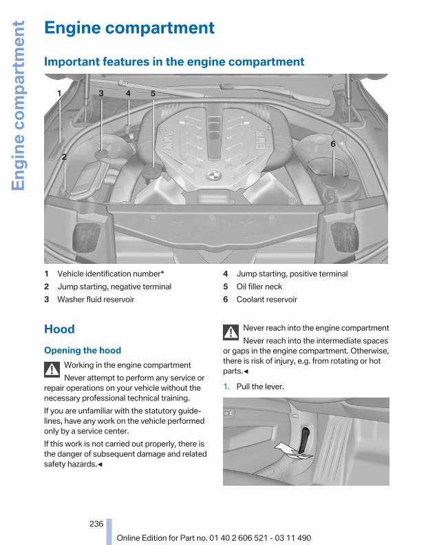
Engine compartmentImportant features in the engine compartment
1 Vehicle identification number*2 Jump starting, negative terminal3 Washer fluid reservoir
4 Jump starting, positive terminal5 Oil filler neck6 Coolant reservoir
HoodOpening the hood
Working in the engine compartmentNever attempt to perform any service or
repair operations on your vehicle without thenecessary professional technical training.If you are unfamiliar with the statutory guide‐lines, have any work on the vehicle performedonly by a service center.If this work is not carried out properly, there isthe danger of subsequent damage and relatedsafety hazards.◀
Never reach into the engine compartmentNever reach into the intermediate spaces
or gaps in the engine compartment. Otherwise,there is risk of injury, e.g. from rotating or hotparts.◀
1. Pull the lever.
Seite 236
236Online Edition for Part no. 01 40 2 606 521 - 03 11 490
Engi
ne co
mpa
rtmen
t

2. Press the release handle and open the hood.
3. Be careful of protruding parts on the hood.
Danger of injury when the hood is openThere is a danger of injury from protruding
parts when the hood is open.◀
Closing the hood
Let the hood drop from a height of approx. 16 in/40 cm and push down on it to lock it fully.The hood must audibly engage on both sides.
Hood open when drivingIf you see any signs that the hood is not
completely closed while driving, pull over imme‐diately and close it securely.◀
Danger of pinchingMake sure that the closing path of the
hood is clear; otherwise, injuries may result.◀
Seite 237
237Online Edition for Part no. 01 40 2 606 521 - 03 11 490
Re
fere
nce
Mob
ility
Com
mun
icat
ion
Ente
rtain
men
tNa
vigat
ion
Drivi
ng ti
psCo
ntro
lsAt
a gl
ance

Engine oilGeneral informationThe engine oil consumption is dependent on thedriving style and driving conditions.Therefore, check the engine oil level after everyrefueling using the electronic engine oil levelcheck.
Checking the oil levelThe conceptThe oil level is monitored electronically and dis‐played on the Control Display.
Requirements▷ The engine must be running and warm after
the vehicle has been driven for at least6 miles/10 km.
▷ The vehicle is stopped or being driven on alevel roadway.
Displaying the oil level1. "Vehicle Info"2. "Vehicle status"3. "Engine oil level"
Possible messages▷ "Engine oil level OK"▷ "Measurement not possible at this time."▷ "Measuring engine oil level..."
Duration with the engine running: ap‐prox. 3 minutes.
Duration while driving: approx. 5 minutes.▷ "Engine oil level below minimum. Add 1
quart!"Add oil within the next 125 miles/200 km.
▷ "Engine oil level too high! Have thischecked."Have the vehicle checked immediately.
Too much engine oilHave the vehicle checked immedi‐
ately; otherwise, surplus oil can lead to en‐gine damage.◀
▷ "Measurement inactive. Have thischecked."Note the newly calculated remaining mile‐age until the next oil service. Have the sys‐tem checked as soon as possible.
Adding engine oilFiller neck
When the indicator lights up in the instrumentcluster, add 1 US quart/liter of engine oil withinthe next 125 miles/200 km.
Recommended oil types, refer to page 239.Protect childrenKeep oil, grease, etc., out of reach of chil‐
dren and heed the warnings on the containersto prevent health risks.◀
Seite 238
238Online Edition for Part no. 01 40 2 606 521 - 03 11 490
Engi
ne o
il

Oil typesNote
No oil additivesOil additives may lead to engine damage.◀
Approved oil typesYour service center can advise you on which en‐gine oils have been approved by the manufac‐turer of your vehicle.The engine oil quality is critical for the life of theengine.Only use approved BMW High Performance oil.Approved oils belong to the viscosity gradesSAE 0W-40, SAE 0W-30, SAE 5W-40 and SAE5W-30.
Alternative oil typesIf the approved engine oils are not available, upto 1 US quart/liter of another oil with the follow‐ing specification may be used.API SM quality standards or higher.
CoolantGeneral information
Danger of burns from hot engineDo not open the cooling system while the
engine is hot; otherwise, escaping coolant maycause burns.◀
Suitable additivesOnly use suitable additives; otherwise, en‐
gine damage may occur. The additives areharmful to your health.◀
Coolant consists of water and additives.Not all commercially available additives are suit‐able for your vehicle. Ask your service center forsuitable additives.
Coolant level
Checking1. Let the engine cool.2. Turn the cap of the coolant reservoir slightly
counterclockwise to allow any excess pres‐sure to dissipate, and then open it.
3. The coolant level is correct if it lies betweenthe minimum and maximum marks in thefiller neck.
4. If the coolant is low, slowly add coolant up tothe specified level; do not overfill.
5. Turn the cap until there is an audible click.6. Have the cause of the coolant loss elimi‐
nated as soon as possible.
Seite 239
239Online Edition for Part no. 01 40 2 606 521 - 03 11 490
Re
fere
nce
Mob
ility
Com
mun
icat
ion
Ente
rtain
men
tNa
vigat
ion
Drivi
ng ti
psCo
ntro
lsAt
a gl
ance

DisposalComply with the relevant environmentalprotection regulations when disposingof coolant and coolant additives.
Seite 240
240Online Edition for Part no. 01 40 2 606 521 - 03 11 490
Engi
ne o
il

MaintenanceBMW Maintenance SystemThe maintenance system directs you to re‐quired maintenance measures and thereby sup‐ports you in maintaining road safety and the op‐erational reliability of the vehicle.
Condition Based Service CBSSensors and special algorithms take into ac‐count the driving conditions of your vehicle.Based on this, Condition Based Service deter‐mines the maintenance requirements.The system makes it possible to adapt theamount of maintenance you need to your userprofile.Details on the service requirements, refer topage 81, can be displayed on the Control Dis‐play.
Service data in the remote controlInformation on the required maintenance is con‐tinuously stored in the remote control. Yourservice center will read out this data and suggestthe right array of service procedures for your ve‐hicle.Therefore, hand your service specialist the re‐mote control that you used most recently.
Storage periodsStorage periods during which the vehicle bat‐tery was disconnected are not taken into ac‐count.If this occurs, have a service center update thetime-dependent maintenance procedures,such as checking brake fluid and, if necessary,changing the engine oil and the microfilter/acti‐vated-charcoal filter.
Service and WarrantyInformation Booklet for USmodels and Warranty andService Guide Booklet forCanadian modelsPlease consult your Service and Warranty Infor‐mation Booklet for US models and Warranty andService Guide Booklet for Canadian models foradditional information on service requirements.Maintenance and repair should be performed byyour service center. Make sure to have regularmaintenance procedures recorded in the vehi‐cle's Service and Warranty Information Bookletfor US models, and in the Warranty and ServiceGuide Booklet for Canadian models. These en‐tries are proof of regular maintenance.
Socket for OBD OnboardDiagnosis
There is an OBD socket on the driver's side forchecking the primary components in the vehicleemissions.
Emissions▷ The warning lamp lights up:
Emissions are deteriorating. Havethe vehicle checked as soon as pos‐sible.
▷ The warning lamp flashes under cer‐tain circumstances:
Seite 241
241Online Edition for Part no. 01 40 2 606 521 - 03 11 490
Re
fere
nce
Mob
ility
Com
mun
icat
ion
Ente
rtain
men
tNa
vigat
ion
Drivi
ng ti
psCo
ntro
lsAt
a gl
ance

This indicates that there is excessivemisfiring in the engine.Reduce the vehicle speed and havethe system checked immediately;otherwise, serious engine misfiringwithin a brief period can seriouslydamage emission control compo‐nents, in particular the catalytic con‐verter.
Fuel capThe indicator lamp lights up.If the fuel cap is not properly tightened,the OBD system may conclude that fuel
vapor is escaping. If the cap is then tightened,the display should go out in a short time.
Data memoryYour vehicle records data relating to vehicle op‐eration, faults and user settings. These data arestored in the remote control and can be read outwith suitable devices, particularly when the ve‐hicle is serviced. The data obtained in this wayprovide valuable information for service proc‐esses and repair or for optimizing and develop‐ing vehicle functions further.In addition, if you signed a service contract forAssist, certain vehicle data can be sent directlyfrom the vehicle to facilitate the desired serv‐ices.
Seite 242
242Online Edition for Part no. 01 40 2 606 521 - 03 11 490
Mai
nten
ance
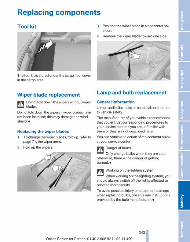
Replacing componentsTool kit
The tool kit is stored under the cargo floor coverin the cargo area.
Wiper blade replacementDo not fold down the wipers without wiperblades
Do not fold down the wipers if wiper blades havenot been installed; this may damage the wind‐shield.◀
Replacing the wiper blades1. To change the wiper blades, fold up, refer to
page 71, the wiper arms.2. Fold up the wipers.
3. Position the wiper blade in a horizontal po‐sition.
4. Remove the wiper blade toward one side.
Lamp and bulb replacementGeneral informationLamps and bulbs make an essential contributionto vehicle safety.The manufacturer of your vehicle recommendsthat you entrust corresponding procedures toyour service center if you are unfamiliar withthem or they are not described here.You can obtain a selection of replacement bulbsat your service center.
Danger of burnsOnly change bulbs when they are cool;
otherwise, there is the danger of gettingburned.◀
Working on the lighting systemWhen working on the lighting system, you
should always switch off the lights affected toprevent short circuits.To avoid possible injury or equipment damagewhen replacing bulbs, observe any instructionsprovided by the bulb manufacturer.◀
Seite 243
243Online Edition for Part no. 01 40 2 606 521 - 03 11 490
Re
fere
nce
Mob
ility
Com
mun
icat
ion
Ente
rtain
men
tNa
vigat
ion
Drivi
ng ti
psCo
ntro
lsAt
a gl
ance
Do not touch the bulbsDo not touch the glass of new bulbs with
your bare hands, as even minute amounts ofcontamination will burn into the bulb's surfaceand reduce its service life.Use a clean tissue, cloth or something similar, orhold the bulb by its base.◀
Light-emitting diodes (LEDs)Light-emitting diodes installed behind a coverserve as the light source for controls, display el‐ements and other equipment.These light-emitting diodes, which are relatedto conventional lasers, are officially designatedas Class 1 light-emitting diodes.
Do not remove the coversDo not remove the covers, and never stare
into the unfiltered light for several hours; other‐wise, irritation of the retina could result.◀
Headlamp glassCondensation can form on the inside of the ex‐ternal lamps in cool or humid weather. When thelight is switched on, the condensation evapo‐rates after a short time. The headlamp glassesdo not need to be changed.If there is a large amount of moisture, e.g., waterdroplets form in the lamp, have it checked byyour service center.
Front lamps, bulb replacement
Xenon headlampsBecause of the long life of these bulbs, the like‐lihood of failure is very low. Switching the lampson and off frequently shortens their life.If a bulb fails, switch on the front fog lamps* andcontinue the trip with great care. Comply withlocal regulations.
Do not perform work/bulb replacement onxenon headlamps
Have any work on the xenon lighting system, in‐cluding bulb replacement, performed only by aservice center.
Due to the high voltage present in the system,there is the danger of fatal injuries if work is car‐ried out improperly.◀
For checking and adjusting headlamp aim,please contact your BMW center.
LEDs or light modulesThe following lamps are equipped with LEDtechnology or are designed as light modules:▷ Parking lamps and roadside parking lamps▷ Turn signal lamps▷ Front fog lamps*▷ Daytime running lights*Contact your service center in the event of amalfunction.Follow the general instructions on lamps andbulbs, refer to page 243.
Corner-illuminating lamps*Follow the general instructions on lamps andbulbs, refer to page 243.The illustration shows the left side of the enginecompartment.55-watt bulb, H3
Seite 244
244Online Edition for Part no. 01 40 2 606 521 - 03 11 490
Repl
acin
g co
mpo
nent
s

1. Unscrew the cap and remove it.
2. Detach the wire bracket.
3. Disconnect the cable at the plug-in connec‐tion and remove the bulb.
4. Insert the new bulb. Ensure that the bulb hasthe correct orientation. Because of itsshape, the bulb can only be inserted in onedirection.
5. Secure the bulb with the wire bracket.6. Connect the bulb.7. Mount the cap.
Tail lamps, bulb replacement
At a glance
1 Turn signal2 Backup lamp
3 Inside brake lamp*4 Tail lamp5 Outside brake lamp6 Rear reflector*
Turn signal, outer brake, tail, andlicense plate lampsFollow the general instructions on lamps andbulbs, refer to page 243.These lights are made using LED technology.Contact your service center in the event of amalfunction.
Lamps in the trunk lid
Access to the lamps
Remove the five screws using the screwdriverfrom the tool kit and fold away the cover.
Inside brake lamp*Follow the general instructions on lamps andbulbs, refer to page 243.24-watt bulb, HP24W
1. Squeeze the bulb holder and pull it out.
2. Pull off the connector.
Seite 245
245Online Edition for Part no. 01 40 2 606 521 - 03 11 490
Re
fere
nce
Mob
ility
Com
mun
icat
ion
Ente
rtain
men
tNa
vigat
ion
Drivi
ng ti
psCo
ntro
lsAt
a gl
ance

3. Replace the bulb.4. Mount the bulb holder and the cover of the
trunk lid in reverse order.
Backup lampFollow the general instructions on lamps andbulbs, refer to page 243.16-watt bulb, W16W
1. Unscrew the bulb holder counterclockwise.
2. Pull out the bulb and replace it.3. Mount the bulb holder and the cover of the
trunk lid in reverse order.
Changing wheelsNotesThe vehicle equipment does not include a sparetire.When using run-flat tires* or tire sealants, a tiredoes not need to be changed immediately in theevent of pressure loss due to a flat tire.The tools for changing wheels are available asaccessories from your service center.
Jacking points for the vehicle jack
The jacking points for the vehicle jack are lo‐cated in the positions shown.
Lug bolt lock*
The lug bolt lock is in the tool kit or in a storagecompartment close to the tool kit.
▷ Lug bolt, arrow 1.▷ Adapter, arrow 2.
Removing1. Attach the adapter to the wheel lug.2. Unscrew the lug bolt.Remove the adapter after screwing the lug boltback on.
Seite 246
246Online Edition for Part no. 01 40 2 606 521 - 03 11 490
Repl
acin
g co
mpo
nent
s

Vehicle batteryMaintenanceThe battery is maintenance-free, i.e., the elec‐trolyte will last for the life of the battery.Your service center will be glad to advise you onquestions regarding the battery.
Battery replacementUse approved vehicle batteries only.Only use vehicle batteries that have been
approved for your vehicle by the manufacturer;otherwise, the vehicle could be damaged andsystems or functions may not be fully availa‐ble.◀
After a battery replacement, have the batteryregistered on the vehicle by your service centerto ensure that all comfort functions are fullyavailable.
Charging the batteryIn the vehicle, only charge the battery via theterminals, refer to page 250, in the engine com‐partment with the engine off.
Power failureAfter a temporary power loss, some equipmentneeds to be reinitialized.Individual settings need to be reprogrammed:▷ Seat, mirror, and steering wheel memory:
store the positions again.▷ Time: update.▷ Date: update.▷ Radio station: save again.▷ Navigation system: wait for the operability of
the navigation.
Disposing of old batteriesHave old batteries disposed of by yourservice center or bring them to a recy‐cling center.
Maintain the battery in an upright position fortransport and storage. Secure the battery sothat it does not tip over during transport.
FusesNotes
Replacing fusesNever attempt to repair a blown fuse and
do not replace a defective fuse with a substituteof another color or amperage rating; this couldlead to a circuit overload, ultimately resulting ina fire in the vehicle.◀
Plastic tweezers and information on the fusetypes and locations are stored in the fuse box inthe cargo area.
In the glove compartment
Push the handle to the side, arrow 1, and openthe lid, arrow 2.
In the cargo area
Open the cover on the right side trim.
Information on the fuse types and locations isfound on a separate sheet.
Seite 247
247Online Edition for Part no. 01 40 2 606 521 - 03 11 490
Re
fere
nce
Mob
ility
Com
mun
icat
ion
Ente
rtain
men
tNa
vigat
ion
Drivi
ng ti
psCo
ntro
lsAt
a gl
ance

Breakdown assistanceHazard warning flashers
The button is located in the center console.
Emergency Request*Requirements▷ Equipment version with full preparation
package mobile phone.An Emergency Request can be made, evenif no mobile phones are paired with the ve‐hicle.
▷ BMW Assist is activated.▷ The radio ready state is switched on.▷ The BMW Assist system is logged in to a
wireless communications network sup‐ported by BMW Assist.
▷ The Assist system is functional.Only press the SOS button in an emergency.
Emergency Request not guaranteedFor technical reasons, the Emergency Re‐
quest cannot be guaranteed under unfavorableconditions.◀
Service contract▷ After your contract with BMW Assist has ex‐
pired, the BMW Assist system can be deac‐tivated by the service center without youhaving to visit a workshop.After deactivation, an Emergency Requestis no longer possible.
▷ Under certain circumstances, the systemcan be reactivated by a service center afteryou sign a new contract.
Initiating an Emergency Request
1. Press the cover briefly to open it.2. Press the SOS button until the LED in the
button lights up.▷ The LED lights up: an Emergency Request
was initiated.If the situation allows, wait in your vehicleuntil the voice connection has been estab‐lished.
▷ The LED flashes if the connection to theBMW Assist Response Center has been es‐tablished.After the Emergency Request arrives at theBMW Assist Response Center, the BMWAssist Response Center contacts you andtakes further steps to help you.Even if you are unable to respond, the BMWAssist Response Center can take furthersteps to help you under certain circumstan‐ces.For this purpose, data that are used to de‐termine the necessary rescue measures,such as the current position of the vehicle ifit can be established, are transmitted to theBMW Assist Response Center.
▷ If the LED is flashing but the BMW AssistResponse Center cannot be heard on thehands-free system, the hands-free systemmay be malfunctioning. However, the BMW
Seite 248
248Online Edition for Part no. 01 40 2 606 521 - 03 11 490
Brea
kdow
n as
sist
ance

Assist Response Center may still be able tohear you.
Initiating an Emergency RequestautomaticallyUnder certain conditions, an Emergency Re‐quest is automatically initiated immediately aftera severe accident. Automatic Collision Notifica‐tion is not affected by pressing the SOS button.
Warning triangle*
The warning triangle is located under a cover onthe left side of the cargo area.Press against the lower edge of the cover andremove the cover.
First aid kit*The first aid kit is located in the insert in the rearseat backrest.
1. Pull the release and remove the insert fromthe front.
2. Remove the first aid kit.
When replacing the insert, place both pins intothe rail at the bottom and press the insert backin place. Ensure that the rear seat backrest up‐holstery is not damaged.Some of the articles have a limited service life.Check the expiration dates of the contents reg‐ularly and replace any items promptly.
Roadside AssistanceService availabilityRoadside Assistance can be reached around theclock in many countries. You can obtain assis‐tance there in the event of a vehicle breakdown.
Roadside AssistanceThe Roadside Assistance, refer to page 219phone number can be viewed on the iDrive or aconnection to Roadside Assistance* can be es‐tablished directly.
Jump startingNotesIf the battery is discharged, an engine can bestarted using the battery of another vehicle andtwo jumper cables. Only use jumper cables withfully insulated clamp handles.To prevent personal injury or damage to bothvehicles, adhere strictly to the following proce‐dure.
Seite 249
249Online Edition for Part no. 01 40 2 606 521 - 03 11 490
Re
fere
nce
Mob
ility
Com
mun
icat
ion
Ente
rtain
men
tNa
vigat
ion
Drivi
ng ti
psCo
ntro
lsAt
a gl
ance

Do not touch live partsTo avoid the risk of potentially fatal injury,
always avoid all contact with electrical compo‐nents while the engine is running.◀
Preparation1. Check whether the battery of the other ve‐
hicle has a voltage of 12 volts. This informa‐tion can be found on the battery.
2. Switch off the engine of the assisting vehi‐cle.
3. Switch off any electronic systems/powerconsumers in both vehicles.
Bodywork contact between vehiclesMake sure that there is no contact be‐
tween the bodywork of the two vehicles; other‐wise, there is the danger of short circuits.◀
Starting aid terminalsConnecting orderConnect the jumper cables in the correct
order; otherwise, there is the danger of injuryfrom sparking.◀
The so-called starting aid terminal in the enginecompartment acts as the battery's positive ter‐minal.
The body ground or a special nut acts as thenegative terminal.
Connecting the cables1. Pull off the cap of the BMW starting aid ter‐
minal.2. Attach one terminal clamp of the positive
jumper cable to the positive terminal of thebattery, or to the corresponding starting aidterminal of the vehicle providing assistance.
3. Attach the other end of the cable to the pos‐itive terminal of the battery, or to the corre‐sponding starting aid terminal of the vehicleto be started.
4. Attach one terminal clamp of the negativejumper cable to the negative terminal of thebattery, or to the corresponding engine orbody ground of the vehicle providing assis‐tance.
5. Attach the other end of the cable to the neg‐ative terminal of the battery, or to the corre‐sponding engine or body ground of the ve‐hicle to be started.
Starting the engineNever use spray fluids to start the engine.
1. Start the engine of the assisting vehicle andlet it run for several minutes at an increasedidle speed.If the vehicle being started has a diesel en‐gine: let the engine of the assisting vehiclerun for approx. 10 minutes.
2. Start the engine of the vehicle being startedin the usual way.If the first starting attempt is not successful,wait a few minutes before making another
Seite 250
250Online Edition for Part no. 01 40 2 606 521 - 03 11 490
Brea
kdow
n as
sist
ance

attempt in order to allow the discharged bat‐tery to recharge.
3. Let both engines run for several minutes.4. Disconnect the jumper cables in the reverse
order.Check the battery and recharge if necessary.
Tow-starting and towingManual transmission
Observe before towing your vehicleThe parking brake is blockedThe parking brake cannot be released
manually.When the parking brake is blocked, do not towwith the front axle lifted or the vehicle can bedamaged.Contact your service center.◀
Gearshift lever in neutral position.
TowingFollow the towing instructionsFollow all towing instructions; otherwise,
vehicle damage or accidents may occur.◀
▷ Make sure that the ignition is switched on;otherwise, the low beams, tail lamps, turnsignals, and windshield wipers may be un‐available.
▷ Do not tow the vehicle with the rear axletilted, as the front wheels could turn.
▷ When the engine is stopped, there is nopower assist. Consequently, more forceneeds to be applied when braking and steer‐ing.
▷ Larger steering wheel movements are re‐quired.
Tow truck
Have your vehicle transported with a tow truckwith a so-called lift bar or on a flat bed.
Do not lift the vehicleDo not lift the vehicle by the tow fitting or
body and chassis parts; otherwise, damage mayresult.◀
Automatic transmission*: transportingyour vehicle
NoteYour vehicle is not permitted to be towed.Therefore, contact a service center in the eventof a breakdown.
Do not have the vehicle towedHave your vehicle transported on a loading
platform only; otherwise, damage may occur.◀
Tow truck
Do not lift the vehicleDo not lift the vehicle by the tow fitting or
body and chassis parts; otherwise, damage mayresult.◀
Use the tow fitting screwed in at the front formaneuvering the vehicle only.
Seite 251
251Online Edition for Part no. 01 40 2 606 521 - 03 11 490
Re
fere
nce
Mob
ility
Com
mun
icat
ion
Ente
rtain
men
tNa
vigat
ion
Drivi
ng ti
psCo
ntro
lsAt
a gl
ance

Towing other vehicles
General informationLight towing vehicleYour vehicle must not be lighter than the
vehicle being towed; otherwise, it will not bepossible to control vehicle response.◀
Attaching the tow bar/tow rope correctlyAttach the tow bar or tow rope to the tow
fitting; connecting it to other vehicle parts maycause damage.◀
▷ Switch on the hazard warning system, de‐pending on local regulations.
▷ If the electrical system has failed, clearlyidentify the vehicle being towed by placinga sign or a warning triangle in the rear win‐dow.
Tow barThe tow fittings used should be on the sameside on both vehicles.Should it prove impossible to avoid mountingthe tow bar at an offset angle, please observethe following:▷ Maneuvering capability is limited during cor‐
nering.▷ The tow bar will generate lateral forces if it
is secured with an offset.
Tow ropeWhen starting to tow the vehicle, make sure thatthe tow rope is taut.To avoid jerking and the associated stresses onthe vehicle components when towing, alwaysuse nylon ropes or nylon straps.
Attaching the tow rope correctlyOnly secure the tow rope on the tow fit‐
ting; otherwise, damage can occur when it is se‐cured on other parts of the vehicle.◀
Tow fitting
The screw-in tow fitting should always be car‐ried in the vehicle. It can be screwed in at thefront or rear of the BMW. It is contained in thetool kit under the cargo floor cover.
Tow fitting, information on use▷ Use only the tow fitting provided with
the vehicle and screw it all the way in.▷ Use the tow fitting for towing on paved roads
only.▷ Avoid lateral loading of the tow fitting, e.g.,
do not lift the vehicle by the tow fitting.Otherwise, damage to the tow fitting and the ve‐hicle can occur.◀
Screw thread
Push out the cover by pressing on the top edge.
Tow-starting
Automatic transmission*Do not tow-start the vehicle.Due to the automatic transmission, the enginecannot be started by tow-starting.Have the cause of the starting difficulties rem‐edied.
Seite 252
252Online Edition for Part no. 01 40 2 606 521 - 03 11 490
Brea
kdow
n as
sist
ance

Manual transmissionIf possible, do not tow-start the vehicle but startthe engine by jump-starting, refer to page 249.If the vehicle is equipped with a catalytic con‐verter, only tow-start while the engine is cold.
1. Switch on the hazard warning system andcomply with local regulations.
2. Ignition, refer to page 65, on.3. Engage third gear.4. Have the vehicle tow-started with the clutch
pressed and slowly release the clutch. Afterthe engine starts, immediately press on theclutch again.
5. Stop at a suitable location, remove the towbar or rope, and switch off the hazard warn‐ing system.
6. Have the vehicle checked.
Seite 253
253Online Edition for Part no. 01 40 2 606 521 - 03 11 490
Re
fere
nce
Mob
ility
Com
mun
icat
ion
Ente
rtain
men
tNa
vigat
ion
Drivi
ng ti
psCo
ntro
lsAt
a gl
ance
CareCar washesNotes
Steam jets or high-pressure washersWhen using steam jets or high-pressure
washers, hold them a sufficient distance awayand use a maximum temperature of 140 ℉/60 ℃.Holding them too close or using excessivelyhigh pressures or temperatures can cause dam‐age or preliminary damage that may then lead tolong-term damage.Follow the operating instructions for the high-pressure washer.◀
Cleaning sensors/cameras with high-pressure washers
When using high-pressure washers, do notspray the exterior sensors and cameras, e.g.,Park Distance Control*, for extended periods oftime and only from a distance of at least 12 in/30 cm.◀
Wash your vehicle frequently, particularly in win‐ter.Intense soiling and road salt can damage the ve‐hicle.
Washing in automatic car washesYour vehicle can be washed in automatic carwashes right from the start.Give preference to cloth car washes or thosethat use soft brushes in order to avoid paintdamage.
NotesNote the following:▷ Make sure that the wheels and tires are not
damaged by the transport mechanisms.▷ Fold in the exterior mirrors; otherwise, they
may be damaged, depending on the width ofthe vehicle.
▷ Deactivate the rain sensor, refer to page 70,to avoid unintentional wiper activation.
▷ Do not treat the convertible top with wax.Ensure that a cycle without wax or a specialcycle for convertibles is available.
▷ In some cases, an unintentional alarm can betriggered by the interior motion sensor of thealarm system*. Follow the instructions onavoiding an unintentional alarm, refer topage 43.
Guide rails in car washesAvoid car washes with guide rails higher
than 4 in/10 cm; otherwise, the vehicle bodycould be damaged.◀
Before driving into a car washThe vehicle is able to roll when the followingsteps are taken:Manual transmission:
1. Shift to neutral.2. Release the parking brake, refer to page 67.3. Switch the engine off.4. Switch on the ignition.Automatic transmission*:
1. Depress the brake pedal.2. Engage transmission position N.3. Release the parking brake, refer to page 67,
or deactivate Automatic Hold, refer topage 67.
4. Switch the engine off.Transmission position P with the igni‐tion off
When the ignition is switched off, position Pis engaged automatically. When in an auto‐matic car wash, for example, ensure that theignition is not switched off accidentally.◀
The vehicle cannot be locked from the outsidewhen in transmission position N.
Seite 254
254Online Edition for Part no. 01 40 2 606 521 - 03 11 490
Care

A signal is sounded when an attempt is made tolock the vehicle.
Transmission positionTransmission position P is engaged automati‐cally:▷ When the ignition is switched off.▷ After approx. 15 minutes.
Headlamps▷ Do not rub dry and do not use abrasive or
caustic cleansers.▷ Soak areas that have been soiled e.g. due to
insects, with shampoo and wash off withwater.
▷ Thaw ice with de-icing spray; do not use anice scraper.
After washing the vehicleAfter washing the vehicle, apply the brakesbriefly to dry them; otherwise, braking action canbe reduced and corrosion of the brake discs canoccur.
Vehicle careCar care productsBMW recommends using cleaning and careproducts from BMW, since these have beentested and approved.
Car care and cleaning productsFollow the instructions on the container.
When cleaning the interior, open the doors orwindows.Only use products intended for cleaning vehi‐cles.Cleansers can contain substances that are dan‐gerous and harmful to your health.◀
Vehicle paintRegular care contributes to driving safety andvalue retention.
Environmental influences can act on the vehiclepaint. Tailor the frequency and extent of your carcare to these influences.
Caring for the convertible topThe appearance and life of the convertible topdepend on correct care and operation.Note the following instructions:▷ To avoid water stains, mildew spots, and
chafe marks, do not fold and stow the con‐vertible top in the convertible top well whilethe top is wet or frozen.
▷ Remove water stains that may neverthelesshave appeared on the headliner using a mi‐crofiber cloth and an interior cleaner.
▷ When the vehicle is parked in enclosedareas for lengthy periods, ensure that thearea is well ventilated.
▷ Remove bird droppings immediately as theircorrosive effect will otherwise attack theconvertible top and damage the rubberseals.
Do not use spot remover, paint thinner,solvent, benzine, or similar products to re‐
move spots on the convertible top. These prod‐ucts may destroy the rubber coating. Incorrectcare and cleaning may cause the convertible topand its seams to become leaky.◀
To remove heavy soiling, use a special conver‐tible top cleaner.Follow the instructions for use from the manu‐facturer.Treat the convertible top with an impregnatingagent after it has been washed three to fivetimes.
Leather careRemove dust from the leather often, using acloth or vacuum cleaner.Otherwise, particles of dust and road grimechafe in pores and folds, and lead to increasedwear and premature degradation of the leathersurface.
Seite 255
255Online Edition for Part no. 01 40 2 606 521 - 03 11 490
Re
fere
nce
Mob
ility
Com
mun
icat
ion
Ente
rtain
men
tNa
vigat
ion
Drivi
ng ti
psCo
ntro
lsAt
a gl
ance

To guard against discoloration, such as fromclothing, provide leather care roughly every twomonths.Clean light-colored leather more frequently asdust and dirt are more noticeable.Use leather care products; otherwise, dirt andgrease will gradually break down the protectivelayer of the leather surface.Suitable care products are available from theservice center.
Upholstery material careVacuum regularly with a vacuum cleaner.If they are very dirty, e.g., beverage stains, use asoft sponge or microfiber cloth with a suitableinterior cleaner.Clean the upholstery down to the seams usinglarge sweeping motions. Avoid rubbing the ma‐terial vigorously.
Damage from Velcro® fastenersOpen Velcro® fasteners on pants or other
articles of clothing can damage the seat covers.Ensure that any Velcro® fasteners are closed.◀
Caring for special components
Light-alloy wheelsUse wheel cleaner, particularly during the wintermonths. Do not use aggressive, acidic, stronglyalkaline or abrasive cleaners, or steam jetsabove 140 ℉/60 ℃; follow the manufacturer'sinstructions.
Chrome surfaces*Carefully clean components such as the radiatorgrille or door handles with an ample supply ofwater, possibly with shampoo added, particu‐larly when they have been exposed to road salt.
Rubber componentsAside from water, treat only with rubber cleans‐ers.When cleaning rubber seals, do not use any sil‐icon-containing car care products in order toavoid damage or reduced noise damping.
Fine wood parts*Clean fine wood facing and fine wood compo‐nents only with a moist rag. Then dry with a softcloth.
Plastic componentsThese include:▷ Imitation leather surfaces.▷ Headliner.▷ Lamp lenses.▷ Instrument cluster cover.▷ Matte black spray-coated components.Clean with a microfiber cloth.Moisten the cloth lightly and use plasticcleanser, if necessary.Do not soak the headliner.
Do not use cleansers that contain alcoholor solvents
Do not use cleansers that contain alcohol or sol‐vents, such as lacquer thinners, heavy-dutygrease removers, fuel, or such; this could lead tosurface damage.◀
Safety beltsDirty belt straps impede the reeling action andthus have a negative impact on safety.
Chemical cleaningDo not clean chemically; this can destroy
the webbing.◀
Use only a mild soapy solution, with the safetybelts clipped into their buckles.Do not allow the reels to retract the safety beltsuntil they are dry.
Floor carpets and floor mats*No objects in the area around the pedalsKeep floor mats, carpets, and any other
objects out of the area of motion of the pedals;otherwise, the function of the pedals could beimpeded while drivingDo not place additional floor mats over existingmats or other objects.
Seite 256
256Online Edition for Part no. 01 40 2 606 521 - 03 11 490
Care

Only use floor mats that have been approved forthe vehicle and can be properly fixed in place.Ensure that the floor mats are securely fastenedagain after they were removed for cleaning, forexample.◀
Floor mats can be removed from the passengercompartment for cleaning.If the floor carpets are very dirty, clean with amicrofiber cloth and water or a textile cleaner. Toprevent matting of the carpet, rub back and forthin the direction of travel only.
Sensors/camerasTo clean sensors and cameras, use a cloth mois‐tened with a small amount of glass cleaner.
Displays/screensClean the displays with a microfiber cloth.
Cleaning displaysDo not use chemical or household cleans‐
ers.Keep all fluids and moisture away from the unit.Otherwise, they could affect or damage surfa‐ces or electrical components.Avoid pressing too hard when cleaning and donot use abrasive materials; otherwise, damagecan result.◀
Long-term vehicle storageYour service center can advise you on what toconsider when storing the vehicle for longerthan three months.
Seite 257
257Online Edition for Part no. 01 40 2 606 521 - 03 11 490
Re
fere
nce
Mob
ility
Com
mun
icat
ion
Ente
rtain
men
tNa
vigat
ion
Drivi
ng ti
psCo
ntro
lsAt
a gl
ance

Online Edition for Part no. 01 40 2 606 521 - 03 11 490

ReferenceThis chapter contains technical data, short
commands for the voice activation system, and anindex that will quickly take you to the information
you need.
Online Edition for Part no. 01 40 2 606 521 - 03 11 490

Technical dataDimensionsWidth, height
1 Vehicle height: 53.8 inches / 1,365 mm2 Vehicle width without mirrors: 74.6 in‐
ches / 1,894 mm3 Vehicle width with mirrors: 81.9 in‐
ches / 2,081 mm
Seite 260
260Online Edition for Part no. 01 40 2 606 521 - 03 11 490
Tech
nica
l dat
a

Length, wheel base
1 Wheel base: 112.4 inches / 2,855 mm2 Length: 192.8 inches / 4,896 mm
Smallest turning circleDia.: 38 ft 5 inches/11.7 m
Weights
650i
Approved gross vehicle weight
Manual transmissionSport automatic transmission
lbs/kglbs/kg
5,401/2,4505,401/2,450
Load lbs/kg 772/350
Approved front axle load lbs/kg 2,679/1,215
Approved rear axle load lbs/kg 2,910/1,320
Cargo area capacityWith cargo area partition flipped up
cu ft/lcu ft/l
10.6/30012.4/350
Seite 261
261Online Edition for Part no. 01 40 2 606 521 - 03 11 490
Re
fere
nce
Mob
ility
Com
mun
icat
ion
Ente
rtain
men
tNa
vigat
ion
Drivi
ng ti
psCo
ntro
lsAt
a gl
ance

Capacities
Notes
Fuel tank US gal/liters approx. 18.5/70 Fuel quality, referto page 228
Windshield and headlampwasher system
US quarts/liters approx. 5.3/5.0
Seite 262
262Online Edition for Part no. 01 40 2 606 521 - 03 11 490
Tech
nica
l dat
a
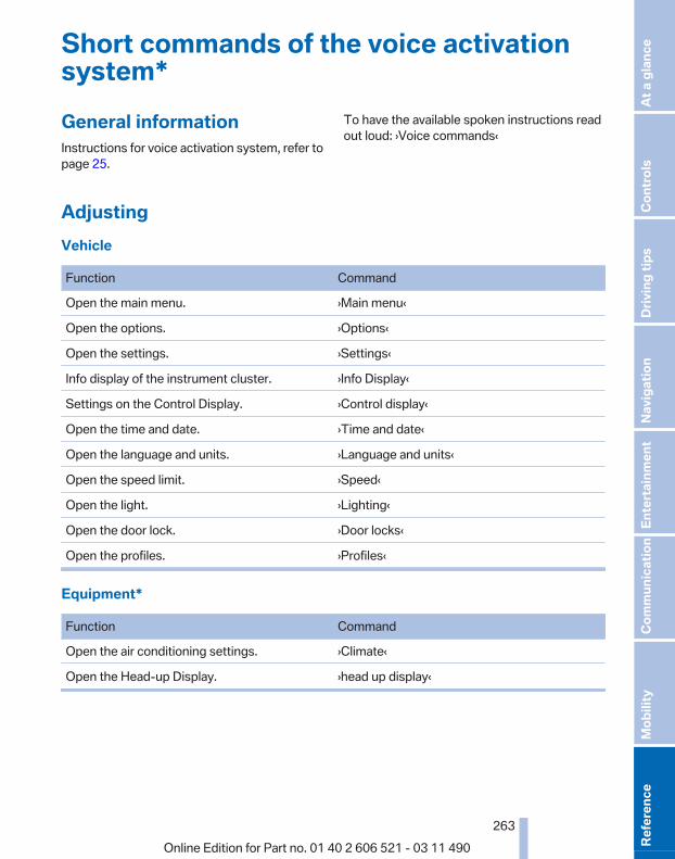
Short commands of the voice activationsystem*General informationInstructions for voice activation system, refer topage 25.
To have the available spoken instructions readout loud: ›Voice commands‹
AdjustingVehicle
Function Command
Open the main menu. ›Main menu‹
Open the options. ›Options‹
Open the settings. ›Settings‹
Info display of the instrument cluster. ›Info Display‹
Settings on the Control Display. ›Control display‹
Open the time and date. ›Time and date‹
Open the language and units. ›Language and units‹
Open the speed limit. ›Speed‹
Open the light. ›Lighting‹
Open the door lock. ›Door locks‹
Open the profiles. ›Profiles‹
Equipment*
Function Command
Open the air conditioning settings. ›Climate‹
Open the Head-up Display. ›head up display‹
Seite 263
263Online Edition for Part no. 01 40 2 606 521 - 03 11 490
Re
fere
nce
Mob
ility
Com
mun
icat
ion
Ente
rtain
men
tNa
vigat
ion
Drivi
ng ti
psCo
ntro
lsAt
a gl
ance

Vehicle informationOwner's Manual
Function Command
Open the Owner's Manual. ›Display Owner's Manual‹
Open the Quick Reference Guide. ›Quick reference‹
Open the index. ›Owner's Manual‹
Open the search by pictures. ›Search by pictures‹
Computer
Function Command
Open the computer. ›Onboard info‹
Open the trip computer. ›Trip computer‹
Vehicle
Function Command
Open the vehicle information. ›Vehicle info‹
Open the vehicle status. ›Vehicle status‹
Navigation*General information
Function Command
Navigation menu. ›Navigation‹
Open the destination entry. ›Enter address‹
Enter the address. ›Enter address‹
Open destination guidance. ›Guidance‹
Start destination guidance. ›Start guidance‹
Terminate destination guidance. ›Stop guidance‹
Open the home address. ›Home address‹
Open the route criteria. ›Route preference‹
Seite 264
264Online Edition for Part no. 01 40 2 606 521 - 03 11 490
Shor
t com
man
ds o
f the
voic
e ac
tivat
ion
syst
em
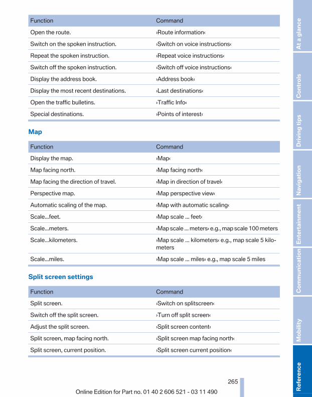
Function Command
Open the route. ›Route information‹
Switch on the spoken instruction. ›Switch on voice instructions‹
Repeat the spoken instruction. ›Repeat voice instructions‹
Switch off the spoken instruction. ›Switch off voice instructions‹
Display the address book. ›Address book‹
Display the most recent destinations. ›Last destinations‹
Open the traffic bulletins. ›Traffic Info‹
Special destinations. ›Points of interest‹
Map
Function Command
Display the map. ›Map‹
Map facing north. ›Map facing north‹
Map facing the direction of travel. ›Map in direction of travel‹
Perspective map. ›Map perspective view‹
Automatic scaling of the map. ›Map with automatic scaling‹
Scale...feet. ›Map scale ... feet‹
Scale...meters. ›Map scale ... meters‹ e.g., map scale 100 meters
Scale...kilometers. ›Map scale ... kilometers‹ e.g., map scale 5 kilo‐meters
Scale...miles. ›Map scale ... miles‹ e.g., map scale 5 miles
Split screen settings
Function Command
Split screen. ›Switch on splitscreen‹
Switch off the split screen. ›Turn off split screen‹
Adjust the split screen. ›Split screen content‹
Split screen, map facing north. ›Split screen map facing north‹
Split screen, current position. ›Split screen current position‹
Seite 265
265Online Edition for Part no. 01 40 2 606 521 - 03 11 490
Re
fere
nce
Mob
ility
Com
mun
icat
ion
Ente
rtain
men
tNa
vigat
ion
Drivi
ng ti
psCo
ntro
lsAt
a gl
ance

Function Command
Split screen, facing the direction of travel. ›Split screen map in direction of travel‹
Split screen, perspective. ›Split screen perspective‹
Split screen, expanded intersection zoom. ›Splitscreen Exit ramp view‹
Split screen scale...feet. ›Split screen scale ... feet‹ e.g., split screen scale100 feet
Split screen scale...meters. ›Split screen scale ... meters‹ e.g., split screenscale 100 meters
Split screen scale...kilometers. ›Split screen scale ... kilometers‹ e.g., split screenscale 5 kilometers
Split screen scale...miles. ›Split screen scale ... miles‹ e.g., split screenscale 5 miles
Split screen, highlight the traffic situation. ›Split screen, Traffic conditions‹
Split screen, computer. ›Split screen on board info‹
Split screen, trip computer. ›Splitscreen trip computer‹
Split screen, scale automatically. ›Split screen automatic scaling‹
Destination guidance with intermediate destinations
Function Command
Enter a new destination. ›Enter address‹
Trip list. ›Stored trips‹
RadioFM
Function Command
Open a frequency. ›Frequency ... megahertz‹ e.g., 93.5 megahertzor frequency 93.5
Open the radio. ›Radio‹
Open the FM stations. ›F M‹
Open the manual search. ›Manual‹
Seite 266
266Online Edition for Part no. 01 40 2 606 521 - 03 11 490
Shor
t com
man
ds o
f the
voic
e ac
tivat
ion
syst
em

Function Command
Select a frequency range. ›Select frequency‹
Open a station. ›Select station‹
AM
Function Command
Open a frequency. ›Frequency ... Kilohertz‹ e.g., frequency 753 or753 kilohertz
Open the AM stations. ›A M‹
Open the manual search. ›Manual‹
Weather Band
Function Command
Open the Weather Band. ›Weather band‹
Switch on the Weather Band. ›Weather band on‹
Select a Weather Band station. ›Select a weather channel‹
Satellite radio*
Function Command
Open the satellite radio. ›Satellite radio‹
Switch on the satellite radio. ›Satellite radio on‹
Select a satellite radio channel. ›Select satellite radio‹ e.g., satellite radio channel2
Stored stations
Function Command
Open the stored stations. ›Presets‹
Choose a stored station. ›Select preset‹
Select a stored station. ›Preset ...‹ e.g., stored station 2
Seite 267
267Online Edition for Part no. 01 40 2 606 521 - 03 11 490
Re
fere
nce
Mob
ility
Com
mun
icat
ion
Ente
rtain
men
tNa
vigat
ion
Drivi
ng ti
psCo
ntro
lsAt
a gl
ance

CD/Multimedia*CD/DVD drive
Function Command
Select a track. ›Track ...‹ e.g., track 5or›C D track ...‹ e.g., CD track 5
Play back a CD. ›C D on‹
Select a CD. ›Select C D‹
Select a CD and track. ›C D ... track ...‹ e.g., CD 3 track 5
Open the CD and Multimedia menu. ›C D and multimedia‹
CD and DVD. ›C D‹
Select a DVD. ›D V D ...‹ e.g. DVD 3
Display the entertainment details on a splitscreen.
›Entertainment details‹
Music collection
Function Command
Search for music, open a menu. ›Music search‹
Open the current playback. ›Current playback‹
Open the music collection. ›Music collection‹
Play back the music collection. ›Music collection on‹
Play back the most frequently played tracks. ›Top fifty‹
External devices
Function Command
Open the external devices. ›External devices‹
Open the Bluetooth devices. ›Bluetooth‹
AUX at front. ›AUX front‹
Seite 268
268Online Edition for Part no. 01 40 2 606 521 - 03 11 490
Shor
t com
man
ds o
f the
voic
e ac
tivat
ion
syst
em

Tone
Function Command
Open the tone settings. ›Tone‹
Telephone*
Function Command
Dial a phone number. ›Dial number‹
Open the Telephone menu. ›Telephone‹
Display the phone book. ›Phonebook‹
Redialing. ›Redial‹
Display received calls. ›Received calls‹
List of messages ›Messages‹
Open the Bluetooth devices. ›Bluetooth‹
Office*
Function Command
Open the Office menu. ›Office‹
Display Office Today. ›Current office‹
Display the contacts. ›Contacts‹
Display the messages. ›Messages‹
Display the calendar. ›Calendar‹
Display the tasks. ›Tasks‹
Display the reminders. ›Reminders‹
Seite 269
269Online Edition for Part no. 01 40 2 606 521 - 03 11 490
Re
fere
nce
Mob
ility
Com
mun
icat
ion
Ente
rtain
men
tNa
vigat
ion
Drivi
ng ti
psCo
ntro
lsAt
a gl
ance

Contacts*
Function Command
Select a name. ›Choose name‹
My contacts. ›My contacts‹
Open the contacts. ›Contacts‹
New contact. ›New contact‹
BMW ConnectedDrive*
Function Command
Open BMW ConnectedDrive. ›Connected Drive‹
Open BMW Search. ›B M W Online‹
Seite 270
270Online Edition for Part no. 01 40 2 606 521 - 03 11 490
Shor
t com
man
ds o
f the
voic
e ac
tivat
ion
syst
em

Seite 271
271Online Edition for Part no. 01 40 2 606 521 - 03 11 490
Re
fere
nce
Mob
ility
Com
mun
icat
ion
Ente
rtain
men
tNa
vigat
ion
Drivi
ng ti
psCo
ntro
lsAt
a gl
ance

Everything from A to ZIndexAABS, Antilock Brake Sys‐
tem 101 Activated-charcoal filter 126 Active Blind Spot Detec‐
tion 98 Active seat, front 55 Active seat ventilation,
front 55 Active Steering, integral 102 Adaptive brake lights, refer to
Brake force display 100 Adaptive drive 102 Adaptive light control 85 Additional telephone 196 Additives, oil 239 Adjustments, seats/head re‐
straints 53 Airbags 88 Airbags, indicator/warning
light 89 Air circulation, refer to Recir‐
culated-air mode 125 Air distribution, manual 123 Air drying, refer to Cooling
function 125 Air pressure, tires 229 Air vents, refer to Ventila‐
tion 126 Air volume, automatic climate
control 124 Alarm system 42 Alarm, unintentional 43 All around the center con‐
sole 17 All around the interior rearview
mirror 18 All around the steering
wheel 12 ALL program, automatic cli‐
mate control 125
All-season tires, refer to Win‐ter tires 233
Alternating-code hand-heldtransmitter 129
Alternative oil types 239 AM/FM station 166 Announcement, navigation,
refer to Spoken instruc‐tions 155
Antifreeze, washer fluid 71 Antilock Brake System,
ABS 101 Anti-slip control, refer to
DSC 101 Appointments 212 Approved engine oils 239 Apps 222 Armrest, refer to Center arm‐
rest 132 Arrival time 78 Ashtray 129 Assist 218 Assistance, Roadside Assis‐
tance 249 Assistance when driving
off 101 Audio playback 173 Audio playback, Blue‐
tooth 188 AUTO intensity 124 Automatic car wash 254 Automatic Curb Monitor 59 Automatic deactivation, front
passenger airbags 89 Automatic headlamp con‐
trol 85 Automatic Hold 67 Automatic locking 39 Automatic recirculated-air
control 125 Automatic Soft Closing,
doors 40
Automatic transmission withSteptronic 72
AUTO program, automatic cli‐mate control 124
AUTO program, intensity 124 AUX-IN port 184 Average fuel consumption 77 Average speed 77 Axle loads, weights 261
BBackrest curvature, refer to
Lumbar support 54 Backrest, seats 53 Backrest, width 54 Backup camera 110 Backup lamps, bulb replace‐
ment 245 Balance 164 Band-Aids, refer to First aid
kit 249 Bar for tow-starting/tow‐
ing 252 Bass 164 Battery replacement, vehicle
battery 247 Battery replacement, vehicle
remote control 32 Battery, vehicle 247 Before entering the car
wash 254 Belts, safety belts 56 Beverage holder, cu‐
pholder 133 Bluetooth audio 188 BMW Apps 222 BMW Apps, video play‐
back 187 BMW Assist 218 BMW EfficientDynamics, refer
to Saving fuel 141 BMW homepage 6
Seite 272
272Online Edition for Part no. 01 40 2 606 521 - 03 11 490
Ever
ythi
ng fr
om A
to Z

BMW Internet page 6 BMW Maintenance Sys‐
tem 241 BMW Online 220 Bottle holder, refer to Cu‐
pholder 133 Brake assistant 101 Brake discs, breaking in 138 Brake force display 100 Brake lamps, brake force dis‐
play 100 Brake lamps, bulb replace‐
ment 245 Brake lights, adaptive 100 Brake pads, breaking in 138 Braking, notes 139 Breakdown assis‐
tance 248, 249 Breaking in 138 Brightness of Control Dis‐
play 80 Bulb replacement 243 Bulb replacement, front 244 Bulb replacement, rear 245 Bulbs and lamps 243 Button, Start/Stop 65 Bypassing, refer to starting
aid 249
CCalendar 212 California Proposition 65
Warning 7 Camera, backup camera 112 Camera, care 257 Camera, Side View 115 Camera, Top View 114 Can holder, refer to Cu‐
pholder 133 Car battery 247 Car care products 255 Care, displays 257 Care, vehicle 255 Cargo 140 Cargo area, cargo area parti‐
tion 47 Cargo area lid 40
Cargo area partition 47 Cargo area, storage compart‐
ments 134 Cargo straps, securing
cargo 141 Car key, refer to Remote con‐
trol 32 Carpet, care 256 Car wash 254 Catalytic converter, refer to
Hot exhaust system 138 CBS Condition Based Serv‐
ice 241 CD/DVD 173 CDs, storing 180 Cell phone 196 Center armrest 132 Center console 17 Central locking system 35 Central screen, refer to Control
Display 19 Changes, technical, refer to
Safety 7 Changing parts 243 Changing wheels/tires 233 Check Control 82 Children, seating position 62 Children, transporting
safely 62 Child restraint fixing sys‐
tem 62 Child restraint fixing system
LATCH 63 Child restraint fixing systems,
mounting 62 Child seat, mounting 62 Child seats 62 Chrome parts, care 256 Cigarette lighter 129 Cleaning, displays 257 Climate control 123 Climate control wind‐
shield 139 Clock 76 Closing/opening from in‐
side 39 Closing/opening via door
lock 38
Closing/opening with remotecontrol 36
Combination instrument 14 Combination instrument, elec‐
tronic displays 16 Combination switch, refer to
Turn signals 69 Combination switch, refer to
Wiper system 69 Comfort Access 41 COMFORT program, Dynamic
Driving Control 105 Computer 76 Concierge service 219 Condensation on win‐
dows 124 Condensation under the vehi‐
cle 140 Condition Based Service
CBS 241 Confirmation signal 37 Contacts 207, 216 Control Display 19 Control Display, settings 79 Controller 19 Control systems, driving sta‐
bility 101 Convenient closing 37 Convenient opening 36 Convertible, convertible
top 45 Convertible mode, automatic
climate control 124 Convertible program, auto‐
matic climate control 124 Convertible top 45 Convertible top, care 255 Convertible top, cargo area
partition 47 Convertible top, emergency
operation 47 Convertible top, rollover pro‐
tection system 91 Convertible top tool 47 Coolant 239 Coolant temperature 75 Cooling function 125 Cooling, maximum 124
Seite 273
273Online Edition for Part no. 01 40 2 606 521 - 03 11 490
Re
fere
nce
Mob
ility
Com
mun
icat
ion
Ente
rtain
men
tNa
vigat
ion
Drivi
ng ti
psCo
ntro
lsAt
a gl
ance

Cooling system 239 Corrosion on brake discs 140 Cruise control 106 Cruising range 74 Cupholder 133 Current fuel consumption 75 Current location, storing 148 Customer Relations 221
DDamage, tires 232 Damping control, dy‐
namic 102 Data, technical 260 Date 76 Daytime running lights 85 Defrosting, refer to Windows,
defrosting 124 Destination distance 77 Destination guidance 153 Destination guidance with in‐
termediate destinations 152 Destination input, naviga‐
tion 146 Digital clock 76 Digital radio 167 Dimensions 260 Dimmable interior rearview
mirror 60 Direction indicator, refer to
Turn signals 69 Display in front wind‐
shield 121 Display, instrument cluster 74 Display lighting, refer to Instru‐
ment lighting 87 Displays 14 Displays, cleaning 257 Disposal, coolant 240 Disposal, vehicle battery 247 Distance control, refer to
PDC 107 Distance to destination 77 Divided screen view, split
screen 23 Door lock, refer to Remote
control 32
Doors, Automatic Soft Clos‐ing 40
Drive-off assistant 101 Drive-off assistant, refer to
DSC 101 Driving instructions, breaking
in 138 Driving notes, general 138 Driving stability control sys‐
tems 101 Driving tips 138 DSC Dynamic Stability Con‐
trol 101 DTC Dynamic Traction Con‐
trol 101 DVD/CD 173 DVD/CD notes 179 DVD changer 177 DVD settings 176 DVDs, storing 180 DVD, video 175 Dynamic Damping Con‐
trol 102 Dynamic destination guid‐
ance 159 Dynamic Drive 102 Dynamic Driving Control 103 Dynamic Stability Control
DSC 101 Dynamic Traction Control
DTC 101
EEfficientDynamics, refer to
Saving fuel 141 Electronic displays, instru‐
ment cluster 16 Electronic engine oil level
check 238 Electronic Stability Program
ESP, refer to DSC 101 Emergency detection, remote
control 33 Emergency operation, conver‐
tible top 47 Emergency release, door
lock 39
Emergency release, fuel fillerflap 226
Emergency Request 248 Emergency service, refer to
Roadside Assistance 249 Emergency start function, en‐
gine start 33 Emergency unlocking, trunk
lid 41 Energy Control 75 Energy recovery 76 Engine compartment 236 Engine compartment, working
in 236 Engine coolant 239 Engine oil 238 Engine oil, adding 238 Engine oil additives 239 Engine oil filler neck 238 Engine oil temperature 75 Engine oil types, alterna‐
tive 239 Engine oil types, ap‐
proved 239 Engine start during malfunc‐
tion 33 Engine start, refer to Starting
the engine 66 Engine start, Starting aid 249 Engine stop 66 Engine temperature 75 Entering/exiting vehicle, assis‐
tance, steering wheel 61 Equalizer 164 Equipment, interior 128 ESP Electronic Stability Pro‐
gram, refer to DSC 101 Exchanging wheels/tires 233 Exhaust system 138 Exterior mirror, automatic dim‐
ming feature, dimmable exte‐rior mirrors 60
Exterior mirrors 59 External devices 184 External start 249 External temperature dis‐
play 75
Seite 274
274Online Edition for Part no. 01 40 2 606 521 - 03 11 490
Ever
ythi
ng fr
om A
to Z

External temperature warn‐ing 75
Eyes for securing cargo 141
FFader 164 Failure message, refer to
Check Control 82 False alarm, refer to Uninten‐
tional alarm 43 Fan, refer to Air volume 124 Fault displays, refer to Check
Control 82 Filler neck for engine oil 238 Fine wood, care 256 First aid kit 249 Fitting for towing, refer to Tow
fitting 252 Flat Tire Monitor FTM 95 Flat tire, Tire Pressure Monitor
TPM 91 Flat tire, warning lamp 93, 95 Flat tire, wheel change 246 Flooding 139 Floor carpet, care 256 Floor mats, care 256 FM/AM station 166 Fold-out position, windshield
wipers 71 Foot brake 139 Front airbags 88 Front fog lamps 87 Front lamps 244 Front passenger airbags, au‐
tomatic deactivation 89 Front passenger airbags, indi‐
cator lamp 90 Front seats 53 FTM Flat Tire Monitor 95 Fuel cap 226 Fuel consumption, current 75 Fuel consumption, refer to
Average fuel consump‐tion 77
Fuel filler flap 226 Fuel gauge 74 Fuel quality 228
Fuel, tank capacity 262 Fuse 247
GGarage door opener, refer to
Integrated universal remotecontrol 128
Gas station recommenda‐tion 155
Gear change, automatic trans‐mission 72
Gear shift indicator 79 General driving notes 138 Glove compartment 132 GPS navigation, refer to Navi‐
gation system 146 Gross vehicle weight, ap‐
proved 261 Gross weight, permissible for
trailer towing 261
HHand brake, refer to Parking
brake 67 Hand-held transmitter, alter‐
nating code 129 Hazard warning flashers 248 HD Radio 167 Headlamp control, auto‐
matic 85 Headlamp courtesy delay fea‐
ture 84 Headlamp courtesy delay fea‐
ture via remote control 37 Headlamp flasher 69 Headlamp glass 244 Headlamps 244 Headlamps, care 255 Headlamp washer system 69 Head restraints 53 Head restraints, front 57 Head-up Display 121 Head-up Display, care 257 Heavy cargo, stowing 141 Height, seats 53 Height, vehicle 260
High-beam Assistant 86 High beams 69 High beams/low beams, refer
to High-beam Assistant 86 Hills 140 Hill start assistant, refer to
Drive-off assistant 101 Hints 6 Holder for beverages 133 Homepage 6 Hood 236 Horn 12 Hotel function 39 Hot exhaust system 138 House number, entering for
navigation 147 Hydroplaning 139
IIce warning, refer to External
temperature warning 75 Icy roads, refer to External
temperature warning 75 Identification marks, tires 231 Identification number, refer to
Engine compartment 236 iDrive 19 Ignition key, refer to Remote
control 32 Ignition off 65 Ignition on 65 Indication of a flat tire 93, 95 Indicator and warning mes‐
sages 14 Indicator lamps 14 Individual air distribution 123 Individual settings, refer to
Personal Profile 33 Inflation pressure, tires 229 Inflation pressure warning
FTM, tires 95 Info display, refer to Com‐
puter 76 Information on the navigation
data 160 Initialization, Integral Active
Steering 103
Seite 275
275Online Edition for Part no. 01 40 2 606 521 - 03 11 490
Re
fere
nce
Mob
ility
Com
mun
icat
ion
Ente
rtain
men
tNa
vigat
ion
Drivi
ng ti
psCo
ntro
lsAt
a gl
ance

Initializing, Flat Tire MonitorFTM 95
Initializing, Tire Pressure Mon‐itor TPM 92
Instrument cluster 14, 74 Instrument cluster, electronic
displays 16 Instrument lighting 87 Integral Active Steering 102 Integrated key 32 Integrated universal remote
control 128 Intensity, AUTO program 124 Interactive map 150 Interior equipment 128 Interior lamps 87 Interior lamps via remote con‐
trol 37 Interior motion sensor 43 Interior rearview mirror 60 Interior rearview mirror, auto‐
matic dimming feature 60 Intermediate destinations 152 Internet page 6 Intersection, entering for navi‐
gation 147 Interval display, service re‐
quirements 81 iPod/iPhone 185
JJacking points for the vehicle
jack 246 Jack, refer to Vehicle jack 246 Joystick, automatic transmis‐
sion 72
KKey/remote control 32 Keyless Go, refer to Comfort
Access 41 Key Memory, refer to Personal
Profile 33 Kickdown, automatic trans‐
mission 72 Knee airbag 88
LLamp replacement 243 Lamp replacement, front 244 Lamp replacement, rear 245 Lamps 84 Lamps and bulbs 243 Lane departure warning 97 Lane margin, warning 97 Language on Control Dis‐
play 80 Lashing eyes, securing
cargo 141 LATCH child restraint fixing
system 63 Leather, care 255 LEDs, light-emitting di‐
odes 244 Length, vehicle 261 Letters and numbers, enter‐
ing 24 License plate lamp, bulb re‐
placement 245 Light-alloy wheels, care 256 Light control 85 Light-emitting diodes,
LEDs 244 Lighting 84 Lighting via remote control 37 Light switch 84 Load 141 Loading 140 Lock, door 38 Locking/unlocking from in‐
side 39 Locking/unlocking via door
lock 38 Locking/unlocking with re‐
mote control 36 Locking, automatic 39 Locking, central 35 Locking via trunk lid 41 Low beams 84 Low beams, automatic, refer to
High-beam Assistant 86 Lower back support 54 Lug bolt lock 246 Lumbar support 54
MMaintenance 241 Maintenance require‐
ments 241 Maintenance, service require‐
ments 81 Maintenance System,
BMW 241 Malfunction displays, refer to
Check Control 82 Manual air distribution 123 Manual air volume 124 Manual brake, refer to Parking
brake 67 Manual mode, transmis‐
sion 73 Manual operation, backup
camera 110 Manual operation, door
lock 39 Manual operation, exterior mir‐
rors 59 Manual operation, fuel filler
flap 226 Manual operation, Park Dis‐
tance Control PDC 108 Manual operation, Side
View 114 Manual operation, Top
View 113 Manual transmission 71 Map, destination entry 150 Map in split screen 157 Map view 155 Marking on approved
tires 233 Marking, run-flat tires 234 Massage seat, front 55 Master key, refer to Remote
control 32 Maximum cooling 124 Maximum speed, winter
tires 234 Measure, units of 80 Medical kit 249 Memory for seat, mirrors,
steering wheel 58
Seite 276
276Online Edition for Part no. 01 40 2 606 521 - 03 11 490
Ever
ythi
ng fr
om A
to Z
Menu in instrument cluster 76 Menus, operating, iDrive 19 Menus, refer to iDrive operat‐
ing concept 20 Message list, traffic bulle‐
tins 157 Messages 210 Messages, refer to Check
Control 82 Microfilter 126 Minimum tread, tires 232 Mirror 59 Mirror memory 58 Mobile communication devi‐
ces in the vehicle 139 Mobile phone 196 Modifications, technical, refer
to Safety 7 Moisture in headlamp 244 Monitor, refer to Control Dis‐
play 19 Mounting of child restraint fix‐
ing systems 62 MP3 player 184 Multifunction steering wheel,
buttons 12 Multimedia 173 Music collection 180 Music search 181 Music, storing 180
NNavigation 146 Navigation data 160 Neck restraints, front, refer to
Head restraints 57 New wheels and tires 233 Night Vision with pedestrian
detection 118 NORMAL program, Dynamic
Driving Control 105 Notes 213 Nylon rope for tow-starting/
towing 252
OOBD Onboard Diagnos‐
tics 241 Obstacle marking, backup
camera 111 Odometer 76 Office 207 Oil 238 Oil, adding 238 Oil additives 239 Oil change interval, service re‐
quirements 81 Oil filler neck 238 Oil level check 238 Oil types, alternative 239 Oil types, approved 239 Old batteries, disposal 247 Onboard Diagnostics
OBD 241 Onboard monitor, refer to
Control Display 19 Online, refer to BMW On‐
line 220 Opening/closing from in‐
side 39 Opening/closing via door
lock 38 Opening/closing with remote
control 36 Operating concept, iDrive 19 Outside air, refer to Automatic
recirculated-air control 125 Overheating of engine, refer to
Coolant temperature 75
PPaint, vehicle 255 Panic mode 37 Parallel parking assistant 115 Park Distance Control
PDC 107 Parked-car ventilation 126 Parked vehicle, condensa‐
tion 140 Parking aid, refer to PDC 107 Parking assistant 115
Parking brake 67 Parking lamps 84 Parking with Auto Hold 67 Passenger side mirror, tilting
downward 59 Pathway lines, backup cam‐
era 110 PDC Park Distance Con‐
trol 107 Pedestrian detection, refer to
Night Vision 118 People detection, refer to
Night Vision 118 Permissible axle load 261 Personal information 207 Personal Profile 33 Phone 196 Pinch protection system, win‐
dows 44 Plastic, care 256 PlugIn 223 Position, storing 148 Postal code, entering in navi‐
gation 146 Power failure 247 Power windows 43 Pressure, tire air pres‐
sure 229 Pressure warning FTM,
tires 95 Profile, refer to Personal Pro‐
file 33 Programmable memory but‐
tons, iDrive 23 Protective function, win‐
dows 44 Push-and-turn switch, refer to
Controller 19
RRadiator fluid 239 Radio 166 Radio-operated key, refer to
Remote control 32 Radio ready state 65 Rain sensor 70 Random 174
Seite 277
277Online Edition for Part no. 01 40 2 606 521 - 03 11 490
Re
fere
nce
Mob
ility
Com
mun
icat
ion
Ente
rtain
men
tNa
vigat
ion
Drivi
ng ti
psCo
ntro
lsAt
a gl
ance

Random playback 174 RDS 167 Reading out loud 214 Rear axle steering 102 Rear lamps 245 Rearview mirror 59 Rear window defroster 125 Recirculated-air mode 125 Recommended tire
brands 233 Refueling 226 Remaining range 74 Reminders 213 Remote control/key 32 Remote control, malfunc‐
tion 38 Remote control, universal 128 Replacement fuse 247 Replacing parts 243 Replacing wheels/tires 233 Reporting safety defects 8 Reserve warning, refer to
Range 74 Resetting, Tire Pressure Mon‐
itor TPM 92 Residual heat, automatic cli‐
mate control 125 Retaining straps, securing
cargo 141 Retreaded tires 233 Roadside Assistance 219 Roadside parking lamps 85 Rollover protection system 91 Roll stabilization, refer to
Adaptive Drive 102 Roll stabilization, refer to Dy‐
namic Drive 102 Roof load capacity 261 Rope for tow-starting/tow‐
ing 252 Route 154 Route criteria, route 153 Route, displaying 154 Routes, avoiding 154 Route section, bypassing 155 RSC Runflat System Compo‐
nent, refer to Run-flattires 234
Rubber components,care 256
Run-flat tires 234
SSafe braking 139 Safety 7 Safety belt reminder 56 Safety belts 56 Safety belts, care 256 Safety systems, airbags 88 Satellite radio 168 Saving fuel 141 Scale, changing during navi‐
gation 156 Screen, refer to Control Dis‐
play 19 Screwdriver 243 Screw thread for tow fit‐
ting 252 Seat belts, refer to Safety
belts 56 Seat heating, front 55 Seating position for chil‐
dren 62 Seat, mirror, and steering
wheel memory 58 Seats 53 Seat ventilation, front 55 Selection list in instrument
cluster 76 Selector lever, automatic
transmission 72 Sensors, care 257 Service and warranty 7 Service requirements, CBS
Condition Based Serv‐ice 241
Service requirements, dis‐play 81
Service, Roadside Assis‐tance 249
Settings on Control Dis‐play 79
Settings, storing for seat, mir‐rors, steering wheel 58
Shifting, automatic transmis‐sion 72
Shifting, manual transmis‐sion 71
Shift paddles on steeringwheel 73
Short commands 263 Shoulder support 54 Side airbags 88 Side View 114 Signaling, horn 12 Signals when unlocking 37 Sitting safely 53 Size 260 Ski bag 131 Smallest turning circle 261 Smoker's package 129 Snap-in adapter, mobile
phone 205 Snow chains 234 Socket 130 Socket, OBD Onboard Diag‐
nostics 241 Software applications,
iPhone 222 Software update 191 Spare fuse 247 Special destinations, naviga‐
tion 149 Specified engine oil
types 239 Speed, average 77 Speed limit, setting 78 Speedometer 14 Split screen 23 Split screen map settings 157 Spoken instructions, naviga‐
tion 155 SPORT+ program, Dynamic
Driving Control 104 Sport automatic transmis‐
sion 73 SPORT program, Dynamic
Driving Control 104 Sport program, transmis‐
sion 73 Stability control systems 101 Start/Stop button 65
Seite 278
278Online Edition for Part no. 01 40 2 606 521 - 03 11 490
Ever
ythi
ng fr
om A
to Z
Start function during malfunc‐tion 33
Starting aid 249 Starting the engine 66 State/province, selecting for
navigation 146 Stations, stored 172 Station, storing 166 Status display, tires 92 Status information, iDrive 22 Status of Owner's Manual 6 Steering, Integral Active
Steering 102 Steering wheel, adjusting 60 Steering wheel heating 61 Steering wheel memory 58 Steptronic, automatic trans‐
mission 72 Stopping the engine 66 Storage compartments 132 Storage compartments, loca‐
tions 132 Storage, tires 234 Storing the vehicle 257 Street, entering for naviga‐
tion 147 Summer tires, tread 232 Supplementary text mes‐
sage 82 Surround View 110 Suspension settings 103 Switch for Dynamic Driving
Control 103 Switch-on times, parked-car
ventilation 126 Switch, refer to Cockpit 12 Symbols 6
TTachometer 75 Tail and brake lamps 245 Tailgate 40 Tailgate via remote control 37 Tail lamps 245 Tail lamps, bulb replace‐
ment 245 Tasks 213
Technical changes, refer toSafety 7
Technical data 260 TeleService 218 Temperature, automatic cli‐
mate control 124 Temperature display, external
temperature 75 Temperature, engine oil 75 Terminal, starting aid 250 Text messages 210 Text message, supplemen‐
tary 82 Theft alarm system, refer to
Alarm system 42 Theft protection, lug
bolts 246 Theft protection, refer to Cen‐
tral locking system 35 Thermal camera, refer to Night
Vision 118 Thigh support 54 Tilt alarm sensor 43 Tilt, seats 53 Time of arrival 78 Tire damage 232 Tire identification marks 231 Tire inflation pressure 229 Tire inflation pressure monitor,
refer to FTM 95 Tire Pressure Monitor
TPM 91 Tires, changing 233 Tires, everything on wheels
and tires 229 Tires, run-flat tires 234 Tire tread 232 Toll roads, route 154 Tone 164 Tool kit 243 Tools 243 Top View 112 Total vehicle weight 261 Tow fitting 252 Towing 251 Town/city, navigation 146 Tow-starting 251 Tow truck 251
TPM Tire Pressure Moni‐tor 91
Traction control 101 TRACTION program, Dynamic
Driving Control 104 Traffic bulletins, naviga‐
tion 157 Traffic situation/gray card 158 Transmission, automatic 72 Transmission, manual 71 Transporting children
safely 62 Tread, tires 232 Treble, tone 164 Trip computer 78 Triple turn signal activa‐
tion 69 Trip odometer 76 Truck for tow-starting/tow‐
ing 251 Trunk, cargo area partition 47 Trunk lid 40 Trunk lid, emergency unlock‐
ing 41 Trunk lid, hotel function 39 Trunk lid via remote con‐
trol 37 Turning circle 261 Turning circle lines, backup
camera 111 Turn signals, operation 69 Turn signals, rear, bulb re‐
placement 245
UUnintentional alarm 43 Units of measure 80 Universal remote control 128 Unlock button, automatic
transmission 72 Unlocking/locking from in‐
side 39 Unlocking/locking via door
lock 38 Unlocking/locking with remote
control 36
Seite 279
279Online Edition for Part no. 01 40 2 606 521 - 03 11 490
Re
fere
nce
Mob
ility
Com
mun
icat
ion
Ente
rtain
men
tNa
vigat
ion
Drivi
ng ti
psCo
ntro
lsAt
a gl
ance

Updates made after the edito‐rial deadline 6
Updating software 191 Upholstery care 256 USB audio interface 185 USB interface 132
VVariable steering, Integral Ac‐
tive Steering 102 Vehicle battery 247 Vehicle battery, replacing 247 Vehicle, breaking in 138 Vehicle care 255 Vehicle identification number,
refer to Identification numberin the engine compart‐ment 236
Vehicle jack 246 Vehicle paint 255 Vehicle storage 257 Vehicle wash 254 Ventilation 126 Ventilation, refer to Parked-car
ventilation 126 Version of the navigation
data 160 Video playback 175 Video playback, iPhone 187 Video playback, snap-in
adapter 187 Voice activation, mobile
phone 203 Voice activation, short com‐
mands 263 Voice activation system 25 Volume, setting 164
WWarning lamps 14 Warning messages, refer to
Check Control 82 Warning triangle 249 Washer fluid 71 Washer fluid reservoir, ca‐
pacity 262
Washer nozzles, wind‐shield 71
Washer system 69 Washing, vehicle 254 Water on roads 139 Weather Band 168 Weights 261 Welcome lamps 84 Wheel base, vehicle 261 Wheel change 246 Wheels, changing 233 Wheels, everything on wheels
and tires 229 Wheels, Flat Tire Monitor
FTM 95 Wheels, Tire Pressure Monitor
TPM 91 Width, vehicle 260 Wind deflector 50 Window defroster, rear 125 Windows, powered 43 Windshield, climate con‐
trol 139 Windshield washer fluid 71 Windshield washer noz‐
zles 71 Windshield washer system 69 Windshield wiper 69 Windshield wipers, fold-out
position 71 Winter storage, care 257 Winter tires, suitable tires 233 Winter tires, tread 232 Wiper blades, replacing 243 Wiper fluid 71 Wiper system 69 Wood, care 256 Word match concept, naviga‐
tion 24 Wrench 243
XXenon headlamps, bulb re‐
placement 244
YYour individual vehicle 6
Seite 280
280Online Edition for Part no. 01 40 2 606 521 - 03 11 490
Ever
ythi
ng fr
om A
to Z


More about BMW
bmwusa.comThe Ultimate Driving
Machine
01 4
0 2
606
521
Ue
*BL260652100K*Online Edition for Part no. 01 40 2 606 521 - 03 11 490