Embed Size (px)
Citation preview
1
2
Contents
1 General 3 2 Requirements for Lighting 3 3 Design Brief 3 4 Design Approval 4 5 Documentation Required for Approval 4 6 Design 5 7 Control 6 8 Mounting 7 9 Glare 7 10 Conflict Areas 7 11 Pedestrian Subways and Underpasses 7 12 Other 8 13 Electrical Services 8 14 Installation 9 15 Pre Adoption (Maintenance) Period 10 16 Adoption 10 17 Commuted SUMS 11 18 Equipment specification 11 Appendix 0/2: Contract Specific Minor Alterations to Existing Clauses and Tables Included in this Contract 12 Appendix 1/5: Testing to be Carried Out by Contractor 13 Appendix 5/1: Drainage Requirements 13 Appendix 5/2: Service duct requirements 14 Appendix 12/1: Traffic signs: General 15 Appendix 13/1 Lighting columns and brackets 16 Appendix 14/1 Site records 19 Appendix 14/3 Temporary lighting 20 Appendix 14/4 Electrical equipment for road lighting 20 Appendix 14/5 Electrical equipment for traffic signs 24 Appendix 14/70 Electrical equipment for road lighting and traffic signs 25 Appendix 19/1 Protection of steelwork against corrosion 27 Abbreviations 29 Annex A Approved materials 30 Annex B Inventory Data 31
3
1.0 General 1.1 This document identifies the basic principles and standards for street lighting required by the Lighting
Authority. However this document does not supersede the Lighting Authority policy or plan for street lighting.
1.2 The Lighting Authority reserves the right to alter / amend the standards contained within this document as deemed necessary. 1.3 This document shall be read in conjunction with the following documents:
• Manual of Contract Documents for Highway Works (MCHW) Volumes 1 and 2 • The Lighting Authority - Standard Detail Drawings
2.0 Requirements for Lighting 2.1 The Developer shall adhere to the requirements as outlined in this Specification and the site specific Design Brief (see section 3 below) 2.2 The Developer shall be responsible for undertaking any amendments to existing lighting equipment which is affected as a result of their proposals. 2.3 Where it is determined that lighting should be provided, extended or improved, the Developer shall be
responsible for the supply and installation of that lighting equipment and the associated electrical connections.
3.0 Design Brief
3.1 Before commencing a design the Developer shall contact the Lighting Authority to determine their requirements for street lighting. 3.2 The level and type of lighting will vary with the type and use of the area to be adopted as highway. 3.3 A Design Brief will provide guidance to the lighting designer and shall include (but not limited to) the following:
• Lighting Authority Project Engineer Contact • The lighting class required • Extent of lighting area; • Variable Lighting Requirements • Mounting heights • Control requirements. • Special material requirements (if required)
3.4 If the Developer considers that an alternative lighting class is appropriate, it should be referred to in writing to the Lighting Authority whose decision will be final and binding.
4.0 Design Approval 4.1 Lighting proposals shall be submitted to the Lighting Authority for approval via the Develop Management team;
4
4.2 Designs shall be undertaken by a competent Lighting Designer; 4.3 In order for approval to be given, lighting designs must demonstrate compliance with the requirements of the Lighting Design Brief and this Specification. 4.4 Lighting scheme design approval shall be obtained in writing from the Lighting Authority prior to commencement on site;
5.0 Documentation Required for Approval
5.1 All information specified in the Lighting Design Brief is to be sent electronically to the Lighting Authority
via the Develop Management team. The following information will be required for approval:
(i) Location plan (ii) Adoption plan (“Pink Drawing”) (iii) Lighting design calculations including electronic calculation files, all input data and details of the software package that has been used (lighting plots alone are not acceptable) (iv) Details of design consideration(s) made (v) Survey pictures for S278 schemes (vi) Details of all equipment proposed with supporting certification and documentation (if not detailed in this specification) (vii) Details of power supplies, including cable calculations and schematic drawings (where required) (viii) Column / DNO Connections schedule with Northings and Eastings (ix) Scheme drawings – with minimum and average Lux ISO contour in DWG and PDF format (x) Passive safety risk assessment (as per ILP TR30) (xi) Details of signing layout including supply connections (xii) CDM details (Designer Risk Assessment, H&S File etc.) (xiii) Environmental considerations (if required)
5.2 Lighting Design construction drawings shall;
(i) Be no larger than A1 (ii) Be at a scale of 1:500 or less (i.e. 1:200 etc.) (iii) Have a minimum text size of 2.5mm for A1 drawings and 1.8mm for A3 drawings (iv) Have cut lines where required (v) Have a North point (vi) Shall have a key where symbols can be identified when the drawing is printed in colour or black and white (vii) Show overhead lines (LV, HV and BT), and major services (e.g. HV cable, High/medium pressure gas, fibre optic cable etc.) (viii) Highlight significant hazards that the installer of the street lighting furniture and Lighting
Authority shall have to allow for
6.0 Design
General 6.1 All lighting designs shall be in accordance with BS 5489 and BS EN 13201 (latest editions) or other standards that may be appropriate subject to approval first. 6.2 When approved by the lighting authority, a foot path or cycleway may be considered independent from
the adjacent carriageway. Where this is the case the lighting for the foot path or cycleway shall have a
5
separate calculation grid from the carriageway. Foot paths and cycleways which required separate calculation grids may have a different lighting class classification from the carriageway as specified in the Lighting Brief.
Design Consideration 6.3 The proposed location of the lighting installation shall be inspected to determine the type, arrangement, source, supply details and any existing lighting. 6.4 The street lighting system must be an integral part of the design of the estate and sufficient space for the installation of street lighting shall be provided. 6.4 Columns shall be located on highway land adopted by the Lighting Authority. 6.6 Columns shall not be placed in a shared surface. 6.7 On housing estates, columns shall not be located outside building frontages. It is preferred that columns
be located away from building frontages, however the designer may locate column on the party line of two adjacent properties, or in line with the side wall of a building.
6.8 Lighting columns shall be located at the back of the footway/path wherever possible. , Where no footway
exists they shall be positioned in an adoptable easement not less than 1.0m x 1.0m in area. Where lighting columns are placed in the verge, they shall be placed not less than 1.0m back from the kerb, or greater if the speed limit of road allows as recommended in BS 5489). The lighting column set back shall be increased at the request of the Lighting Authority.
6.9 Designers shall specify tool free mid-hinged columns where maintenance access cannot be achieved from
a Mobile Elevated Work Platform (MEWP), such as in the requirements set out in G39 and any subsequent GS6 surveys. This includes remote footpaths where vehicular access is not possible.
6.10 Where mid-hinge columns are specified, the lighting designer shall ensure that the column is located so
that, when the column is being lowered or raised, the action of the column is not obstructed, and that no part of the column passes over un-adopted land when being lowered.
6.11 Due consideration is to be given to trees and their growth, traffic calming, parking and pedestrians when deciding the locations of lighting columns. 6.12 Within or adjacent to conservation areas, and in other environmentally sensitive areas, heritage style
equipment may be required at the discretion of the Lighting Authority. This will be provided as part of the Lighting Design Brief and may attract a commuted sum.
6.13 The lighting shall provide visual guidance and assist in revealing the run of the road, particularly at
junctions and bends, as described in the latest edition of BS 5489. 6.14 The lighting arrangements shall be co-ordinated with any traffic signing, signalling and surveillance installations. 6.15 Maintenance factors shall be as per manufacturer’s guidelines using a six year bulk clean and, if applicable, change cycle. 6.16 Signs shall only be illuminated where it is a requirement of the latest edition of the TSRGD. 6.17 Lighting designers shall take into account guidance given in the ILP ‘Guidance for the Reduction of Obtrusive Light’;
6
6.18 Lighting designers shall identify if passively safe equipment is required using the ILP TR30. 6.19 The lighting designer shall provide a lighting design that reduces or eliminates the need for passive safe street lighting columns. 6.20 Lighting designers shall identify the most appropriate and acceptable type of lighting for locations in rural,
environmentally sensitive and conservation areas nd luminaires shall conform to a minimum of G6 Glare Class as described in BS EN 13201-2, Table A.1.
6.21 Where P classes are required the lighting designer shall carry out minimum and maximum design
spacing’s using a road design prior to carrying out an area calculation. 6.22 The designer shall ensure that the design is the most economic by maximising column spacing’s, to
minimise the number of columns and energy used as well as to minimise the installation, operating and maintenance costs
6.23 Where P class designs are required, calculation grids shall be per road expect for roads that contain three
of less lighting columns. These roads shall be included in the connecting road where they have the same lighting class.
7.0 Control
Photocells 7.1 When photocells shall be used the designer will clearly specify the regime, and shall be as follows: 7.2 Lighting class P2, M4, C4 and below use 20/20 lux On/Off. 7.3 Lighting class P1, M3, C3 use 35/35 lux On/Off. 7.4 Higher lighting classes shall use a 55/55 lux On/Off.
CMS 7.5 Where street lighting is required as part of a new development, the developer shall ensure that there is
existing cellular architecture coverage for the street lighting to work correctly. This may require an additional base station to be installed as part of the proposed scheme. This shall be installed in an agreed position with the Lighting Authority in order to communicate with the system.
8.0 Mounting
8.1 All luminaires shall be mounted directly onto the lighting column by means of a post top mounting mechanism. 8.2 Brackets shall only be used where a post top mounting facility is not appropriate, such as tree lined areas
and shall be agreed with the Lighting Authority at the design stage. 8.3 No adoptable lighting shall be installed onto buildings unless no alternative is available and it is agreed
with the Lighting Authority at the design stage.
7
9.0 Glare and Light Trespass
9.1 For illuminance designs (P and C classes) the luminaries are to conform to the Glare classification Class as
described in BS EN 13201-2, Table A.1 to provide adequate control of glare:
(i) Where there is a contiguous lighting network within E3 and E4 environmental zones. Luminaires shall conform to Class G2 of or a higher class with lighting intensity above 95° to be 0.0 cd. (ii) Where there is a contiguous lighting network within E1 and E2 environmental zones. Luminaires shall conform to Class G4 or a higher class. (iii) Where there is a contiguous lighting network within E0 environmental zones. Luminaires shall conform to Class G6.
9.2 All lighting designs my take account of the environment that they are located within and maintain light
spill within ILP Guidance Note for the Reduction of Obtrusive Light. GN01.
10.0 Conflict Areas
10.1 Conflict areas will be identified in the design brief and shall be designed as follows:
(i) Conflict areas shall be illuminated to the class as specified in the Design Brief and in compliance with BS 5489. (ii) The conflict area shall be the carriageway only. Any adjacent cycle tracks and footways shall be lit to an appropriate lighting class as defined the design brief. (iii) The application of the conflict area shall be as ILP PLG02. (iv) It shall be noted that the 5 second rule relates to the approach being lit to the correct lighting standard and does not require the approach to be included within the conflict area calculation.
11.0 Pedestrian Subways and Underpasses
11.1 Details for the lighting for pedestrian subways/underpasses shall be included in the Lighting Design Brief from the Lighting Authority. 11.2 PIR sensors shall be incorporated where requested by the Lighting Authority.
12.0 Other
12.1 Cycle ways shall be designed in accordance with the principals of ILP TR23. 12.2 Cycle ways next to the carriageway shall be lit by the carriageway lighting. 12.3 Zebra crossings shall be lit to ILP TR12.
Refuge Beacons 12.4 Refuge beacons shall be designed in accordance with the requirements of the Traffic Signs Manual chapter 4 which states:
The purpose of the beacon shall be to indicate the presence of a refuge which might be obscured by other traffic, the brow of a hill or a bend. It is not normally necessary on refuges which carry lighting columns or traffic light signals.
8
Belisha Beacons 12.5 Belisha beacons shall be design in accordance with the requirements of the Local Authority Traffic Engineer. 12.6 Belisha beacons shall be designed in accordance with the requirements of the Zebra, Pelican and Puffin
Pedestrian Crossings Regulations and General Directions 1997.
Labelling of Special / Cranked Roots 12.7 Cranked roots shall be in accordance with the I.L.P recommendations and this section. 12.8 Cranked root marks shall be manufactured from one piece U.V. stabilized self-adhesive vinyl. 12.9 There are two labels required Type A as detailed on the standard detail drawings and is to be positioned below the Maintenance Number as described above. 12.10 The second label denotes the direction and length of the cranked root and shall be placed facing the
direction of the root as shown on the standard detail drawings. 12.11 The labels shall consist of a neat rectangular reflective red background with no less than a 12mm border, with white gloss numbers sized as maintenance n numbers above. 12.12 The number characters shall be in Helvetica Medium font.
13.0 Electrical Services
13.1 All electrical supplies for connection to the street lighting system will be arranged and paid for, (including
energy) by the Developer, until adoption by the Lighting Authority. 13.2 All supplies shall be DNO, with the exception of illuminated signs, illuminated bollards and belisha
beacons, which shall be fed via a private network. Any amendments shall be agreed with the Lighting Authority at the design stage.
13.3 DNO cut outs shall be located at the bottom of the backboard, unless otherwise stated by the Lighting
Authority and a secondary double pole isolator shall be installed above, fused appropriately for the lamp taking in to account fuse discrimination.
13.4 All electrical supplies shall be unmetered unless agreed at the design stage with the Lighting Authority 13.5 DNO (or IDNO) services shall be single was service cut-out. Two way looped cut-outs shall not be used.
IDNO 13.6 The lighting Authority’s preference is for the Developer to utilise DNO connections. If IDNO’s are used, the
Developer shall provide the Lighting Authority with details of the IDNO and the emergency contact details kept in the base of the lighting equipment and shall be include the information in the Health and Safety File.
13.7 Guidance can be found on the HEA website, Guidance on Independent DNO’s:
http://s248054552.websitehome.co.uk/HE01/ASLEC/HEA_GN_iDNOs_v2.0-110613.pdf.
9
14.0 Installation
14.1 Installation shall be carried out in accordance with the approved layout. If the highway or property layout
is changed from that used for the approved lighting design, the approval of the lighting proposals shall be withdrawn and the developer shall be required to provide a revised lighting proposal for approval.
14.2 For new works on existing adopted highways, e.g. Section 278 works, the Developer shall inform the
Lighting Authority of the programmed works start date, no less than 28 days before commencement on site, (including the maintenance numbers of the items covered by the works).
14.3 Prior to installation, the developer shall arrange for the Lighting Authority to inspect the setting out of the
lighting column positions, and any other street lighting furniture. 14.4 The Developer shall be responsible for the complete installation and commissioning of each unit. 14.5 Street lighting works shall be carried out by a competent contractor who shall be registered under HERS
(Highway Electrical Registration Scheme) and that their operatives are suitably qualified under the National Highway Sector Scheme 8. The Lighting Authority may request proof of accreditation and authorisation of any subcontractor to perform such duties. The Lighting Authority reserves the right to request a resubmission of any test certificates.
14.6 If the development works have scaffolding within 3 meters of a column or impedes access, then until the
scaffolding is removed, that column will become the liability of the Developer to maintain and ensure no damage is incurred. Please ensure that the Lighting Authority is notified.
14.7 Where lighting already exists, the Developer shall maintain an adequate standard of road lighting. Where
columns have to be re-sited, adequate temporary lighting shall be provided and shall be operational before disconnecting existing street lighting. Temporary lighting proposals shall be submitted to the Lighting Authority for approval.
14.8 The street lighting and electrical installation shall be inspected and tested in accordance with BS7671 and
the Specification for Highways Works. The Developer shall give the lighting authority 7 day notice of electrical inspection and testing being carried out so that the Lighting Authority have the opportunity the witness the inspection and testing.
14.9 Copies of electrical test certificates shall be passed to the Lighting Authority within 28 days of inspection, and prior to the issuing of the completion certificate. 14.10 Where it has been agreed that existing columns may be retained as part of the permanent works,
structural testing shall be undertaken in line with nationally recognised methods and copies of the certificates shall be supplied to the Lighting Authority.
15.0 Pre Adoption (Maintenance) Period
15.1 It shall be the Developer’s responsibility to ensure that prospective purchasers are fully aware of the
locations of all street lighting furniture. Any relocation of equipment shall be at the Developer’s expense, prior to handover and shall be within design parameters or included in a complete re-design of the scheme.
15.2 The Developer is responsible for all maintenance until such time as the installation is formally adopted in accordance with the relevant agreements.
10
15.3 The Developer shall be responsible for the mitigation of light intrusion, such as putting up shields if required from the residents or the Lighting Authority. 15.4 For Section 38 developments, the Developer shall be responsible for all energy and maintenance costs
until the date of adoption and will require their own MPAN. 15.5 For section 278 developments, the cost of energy and emergency maintenance shall be taken on by the
Lighting Authority upon issue of the completion certificate. All other costs shall be the responsibility of the Developer.
15.6 Emergency Repair - The Lighting Authority holds the right to make safe, or cause to be made safe, any
equipment that is dangerous (i.e. though vehicular impact damage, etc.) and all reasonable costs shall be chargeable to the Developer.
15.7 The Developer shall give 20 working days’ notice requesting an inspection of the street lighting installation. 15.8 The Developer shall not offer the columns, signs, beacons and bollards for inspection by the Lighting
Authority, until such time as they are confident that all works have been completed satisfactorily as specified by the Lighting Authority and in accordance with this document.
15.9 Final numbering scheme shall be provided by the Lighting Authority. The Developer shall provide road
names and postal addresses for each property so that the maintenance numbers can be specified. The developer shall be responsible for fixing the numbers to the lighting columns (and other street lighting equipment).
16.0 Adoption
16.1 Prior to adoption the Developer shall provide a Health & Safety file which shall include the record
information as detailed in Appendix 14/1 of this specification. 16.2 Once the site is ready for adoption (after the maintenance period), a final inspection will be carried out by the Lighting Authority. 16.3 If the development is not adopted within 5 years, the Lighting Authority reserves the right to review the
suitability of equipment installed and may require it to be upgraded. 16.4 A bulk lamp / LED array change may be required by the Lighting Authority dependent on scheme life. 16.5 Only when the Lighting Authority is satisfied that all equipment has been installed and all issues resolved
will the street lighting system be accepted for adoption.
17.0 Commuted Sums
17.1 Subject to the agreement of the Lighting Authority, where a standard of materials exceeds the standard
specification, and which shall incur higher maintenance costs, a Commuted Sum shall be calculated and agreed prior to the granting of technical approval. The commuted sum shall be payable to the Lighting Authority prior to adoption of the completed scheme.
17.2 Where a higher standard of materials is installed without the agreement of the Lighting Authority and/or
where a Commuted Sum has not be paid, then adoption will not be granted. The ongoing maintenance of the lighting system shall be the responsibility of the Developer or their appointed managing agents.
11
18.0 Equipment Specification
18.1 All new street lighting furniture shall be in accordance with this specification unless agreed by the Lighting Authority. 18.2 Equipment shall be supplied in new and unused condition. 18.3 Electrical equipment shall be stored in weatherproof accommodation. 18.4 The Developer shall ensure that the equipment supplied is compatible with all other equipment with which it is associated. 18.5 Manufacturers shall be certified for the manufacture, supply and verification of apparatus under BS EN ISO 9001. 18.6 Preferred materials are detailed in Annex A.
12
The following shall apply when the Manual of Contract Documents for Highway Works (MCHW) Volumes 1 and 2 is used where Local Authority documentation is not available:
APPENDIX 0/2: CONTRACT SPECIFIC MINOR ALTERATIONS TO EXISTING CLAUSES AND TABLES INCLUDED IN THIS CONTRACT
1421 Clause 1.
Delete “XLPE insulation” and insert “PVC or XLPE insulation” Delete “XLPE or MDPE sheathing” and insert “PVC, XLPE or MDPE sheathing” Delete “or aluminium strip”
1424 Insert after sub-clause 2(j):-
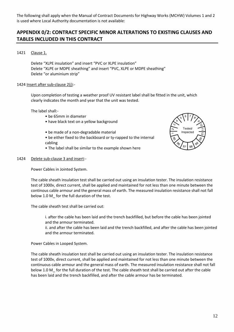
Upon completion of testing a weather proof UV resistant label shall be fitted in the unit, which clearly indicates the month and year that the unit was tested. The label shall:-
• be 65mm in diameter • have black text on a yellow background • be made of a non-degradable material • be either fixed to the backboard or ty-rapped to the internal cabling • The label shall be similar to the example shown here
1424 Delete sub-clause 3 and insert:-
Power Cables in Jointed System.
The cable sheath insulation test shall be carried out using an insulation tester. The insulation resistance test of 1000v, direct current, shall be applied and maintained for not less than one minute between the continous cable armour and the general mass of earth. The measured insulation resistance shall not fall below 1.0 M_ for the full duration of the test. The cable sheath test shall be carried out:
i. after the cable has been laid and the trench backfilled, but before the cable has been jointed and the armour terminated. ii. and after the cable has been laid and the trench backfilled, and after the cable has been jointed and the armour terminated.
Power Cables in Looped System. The cable sheath insulation test shall be carried out using an insulation tester. The insulation resistance test of 1000v, direct current, shall be applied and maintained for not less than one minute between the continuous cable armour and the general mass of earth. The measured insulation resistance shall not fall below 1.0 M_ for the full duration of the test. The cable sheath test shall be carried out after the cable has been laid and the trench backfilled, and after the cable armour has be terminated.
13
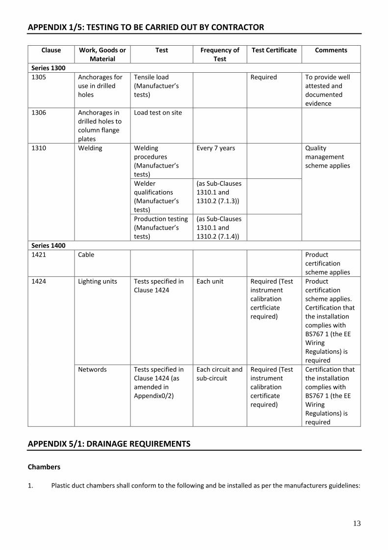
APPENDIX 1/5: TESTING TO BE CARRIED OUT BY CONTRACTOR
Clause Work, Goods or
Material Test Frequency of
Test Test Certificate Comments
Series 1300
1305 Anchorages for use in drilled holes
Tensile load (Manufactuer’s tests)
Required To provide well attested and documented evidence
1306 Anchorages in drilled holes to column flange plates
Load test on site
1310 Welding Welding procedures (Manufactuer’s tests)
Every 7 years Quality management scheme applies
Welder qualifications (Manufactuer’s tests)
(as Sub-Clauses 1310.1 and 1310.2 (7.1.3))
Production testing (Manufactuer’s tests)
(as Sub-Clauses 1310.1 and 1310.2 (7.1.4))
Series 1400
1421 Cable Product certification scheme applies
1424 Lighting units Tests specified in Clause 1424
Each unit Required (Test instrument calibration certficiate required)
Product certification scheme applies. Certification that the installation complies with BS767 1 (the EE Wiring Regulations) is required
Networds Tests specified in Clause 1424 (as amended in Appendix0/2)
Each circuit and sub-circuit
Required (Test instrument calibration certificate required)
Certification that the installation complies with BS767 1 (the EE Wiring Regulations) is required
APPENDIX 5/1: DRAINAGE REQUIREMENTS
Chambers 1. Plastic duct chambers shall conform to the following and be installed as per the manufacturers guidelines:

14
a) Either be 450mm x 450mm, 600mm x 600mm or 900mm x 900mm as stated in the works package drawing. b) Shall be injection moulded with a twin wall construction min. 47mm thick, pre-formed segments to produce a complete ring with stiffeners at min 65mm centres. Each ring section is to be castellated to positively interlock with the unit above and below to form a chamber. c) Be installed with galvanised eye bolt(s) the number required is to be dependent on the required number of draw ropes (see ducting requirement above). An additional eye bolt(s) (as required) is to be installed in each draw pit which is to be used to support column cabling. d) Have a 100mm diameter drain hole cast into the concrete base of the draw pit and be filled level with suitable filter drain material. The foundation shall be cast on site. e) Standard colour black. f) Vertical loading capability of not less than 40 Tonnes. g) Comply with the following Standards:
i. EN124 B125 & D400 Vertical Loading Requirements. ii. BS5834 Part 4. 1993 Side Wall loading for small chambers. iii. BS1247 Part 2. Cold Impact Test. iv. EN228 Resistance to Petrol & Chemicals. v. EN295-3 Stress Relief. vi. BS2782 Part 4. Methods 430A to 430D Water Absorption.
2. Covers and Frames shall conform to EN124 and have load rating as appropriate for the location it is placed (B125, C250 & D400). 3. Shall state ‘Street Lighting’ on the Cover. 4. The Lighting Authority shall be provided with a set of access keys.
APPENDIX 5/2: SERVICE DUCT REQUIREMENTS
Ducts 1. Ducts shall be manufactured from Medium or High Density Polyethylene, with a minimum wall
thickness as follows:
• Min Internal diameter 47mm, normally use 50mm diameter, 3.5mm thickness. • Min Internal Diameter 94mm, normally use 100 mm diameter, 5mm thickness.
2 Ducting shall be in accordance with NJUG guidelines on positioning and colour coding of underground utilities. 3 Private street lighting duct is currently coloured orange and shall be laid at the following depth;
• Minimum of 450mm depth in footway and verge. • Minimum of 750mm in from the carriageway.
4. Equipment requiring a DNO electricity supply shall be fitted with a Black duct for the entrance of the DNO supply cable 5. Ducts shall be fitted with a pigmented, stranded, nylon draw rope of at least 5.0 kN breaking load, the ends of which shall be made fast.
15
APPENDIX 12/1: TRAFFIC SIGNS: GENERAL
1.0 Sign Plate 1.1 Signs shall comply with Class RA 2 of BS EN 12899. 1.2 Sign plates must have a guaranteed on-site life of not less than 25 years. 1.3 Sign plates shall be made from composite material. 1.4 All signs shall be manufactured and erected in accordance with BS EN 12899-1:2007, Traffic Signs
Regulations and General Directions 2016, Traffic Signs Manual, Specification for Highway Works, location plan and associated sign schedules and the following specification.
1.5 The finish shall be Class RA 2 retro-reflective material with a warranted life of not less than ten years and shall fulfil the requirements of BS EN12899-1:2007. 1.6 Signs shall be stiffened such that post fixings may be positioned at any point across the width of the sign
without the need for drilling of the stiffening to permit erection onto posts of unspecified spacing.
2.0 Illuminated Traffic Signs 2.1 Illumination of sign plates shall be external and overhead mounted unless directed otherwise by the
Lighting Authority. One piece light units with integral brackets shall be mounted directly on the sign post and/or on luminaire support posts or as directed by the Lighting Authority.
2.2 All lit traffic signs shall comply with Class RA 2 of BS EN 12899 and sections 7.4.1.2 – Mean Illuminance and 7.4.1.2 – Uniformity of Illuminance. 2.3 All sign and luminaire fixings shall have a guarantee of 25 years on site life. 2.4 Signs which require illuminating shall be mounted on a wide based post 2.5 The orientation of sign post doors shall be in accordance with Standard details. 3.0 Attachments on Columns 3.1 Where signs are to be attached to Lighting Columns, the column shall be designed by the manufacturer to
take the sign size, if the sign is larger than maximum as specified in this specification, this must be highlighted on the drawing and in the scheme contract documents.
3.2 Signs may be attached to existing columns subject to the following:
a) The sign is no larger than the attachment size that the column is designed for. Typically this will be 0.3m2. b) Approval is granted by the lighting authority.
4.0 Sign Posts 4.1 Sign Posts shall conform to BS EN 40, BS12899 and Appendix 13/1, section 4, 5 ,6 & 9 in this document. 4.2 Caps shall be applied to the top of the post to prevent ingress of water.

16
4.3 Posts shall be galvanised steel with two pack glass flake epoxy to the external and internal root to 250mm above ground level, minimum dry film thickness 200μm colour black (shop applied).
5.0 Passively Safe Sign Posts 5.1 Tubular passively safe sign posts shall be provided with a purpose made post cap, coloured to match the post, to prevent ingress of water. 5.2 Only signposts that have been independently tested by an approved testing organisation and certified to
comply with the appropriate class in BS EN 12767 shall be permitted. 5.3 Where signs on passively safe posts require power supply cables for illumination, the cables must be
supplied with a pull-out plug or equivalent arrangement in accordance with BS EN 60309 Parts 1 and 2 and paragraphs 1.2 and 1.3 of TD 89/08.
6.0 Wide Based Posts 6.1 The housing shall have an aperture of not less than 400mm x 115mm and be fitted with a weatherproof
metal door having a vandal-resistant lock with key. The door and housing shall have the same finish as the post, both inside and out.
6.2 Wide based posts shall have an access door and cable entry slot. The cable entry slot shall be 75mm wide
and 150mm high and shall be 500mm below ground level. 6.3 The support posts and fittings shall comply with the requirements for sign posts and shall be fixed directly to the sign stiffening members. 6.4 Caps shall be applied to the top of the post to prevent ingress of water. 6.5 The supply should be as stated in Appendix 14/5.
APPENDIX 13/1 LIGHTING COLUMNS AND BRACKETS
1.0 General Column Requirements 1.1 Please refer to the Standard Details RJ-SD-1300-001 for column general arrangement. 1.2 Amendment to BS EN 40 column Design Life shall be 40 years. 1.3 All columns shall be CE marked in accordance with the European legislation. 1.4 Columns shall comply with BS EN 40 as above, PD6547, and be designed for the location it is being
installed, with the amendment that all columns shall be designed to support attachments (in addition to the luminaire) with the following specification:
• A 2.5m from ground level and area of 1m2 with a min of 0.3m2 at the top of column. • The eccentricity from the centre line of the column to the centre of the area of the attachment
shall be taken as:
300mm for columns up to and including 6m in height.
500mm for columns greater than 6m in height.
1.5 Shall take two hanging baskets weighing 25kg (when wet).
17
1.6 Shall be galvanised steel with two pack glass flake epoxy to the external and internal root to 250mm above ground level, minimum dry film thickness 200μm colour black (shop applied).
1.7 Shall have a 50mm duct in the cable entry hole to protect incoming cable. 1.8 Shall have a welded bead to identify ground level placed below the door with a minimum length of 40mm. 1.9 Columns shall be provided with an earth lug at the bottom left-hand side of the gear compartment to fit the earth wire. 1.10 Columns shall be galvanised to the latest edition of BS EN ISO 1461 Hot Dip Galvanised Coatings on
Fabricated Iron and Steel Articles. Specifications and Test Methods and shall be free from imperfections including porosity. Galvanising shall be fettled and rasped to remove all spikes and sharp edges and leave a smooth finish prior to finishing application.
1.11 Columns shall be coated in accordance with Section 19/1 (where required by the Lighting Authority). 1.12 Be provided complete with 1 key per 40 columns or part thereof. 1.13 Have a baseboard made from material which is substantially non hygroscopic and rotresistant, of not less
than 15mm thickness and suitable size, fixed securely in the base compartment of each column to accommodate all equipment with adequate space left at the bottom for cable termination and service cut-outs.
1.14 Have a tapped stud, set-screw and shake-proof washer to be used as an earthing terminal and this is to be
so positioned as to be easily accessible from the door opening. The screw, shake-proof washers and nuts are to be made of non-corrodible material.
2.0 Column Door Requirements 2.1 Generally have one access door (including double arm columns). Column with CCTV of festive lighting may require columns with two doors. 2.2 The door shall be wrap around with a single clamp fixing arrangement and M8 tri-head stainless steel bolts. 2.3 Door lock type shall be triangular type unless otherwise specified. 2.4 Column doors shall be hinged doors when the column is located on a structure, or is accessed from a structure.
3.0 Special design columns 3.1 Festive decorations and hanging baskets shall not be fitted to columns unless the column and foundation
has been designed for the additional loading and approved by the lighting Authority. 3.2 A license from Lighting Authority shall be required if festive lighting is to be used on any of the columns. 3.3 The installation of CCTV & Mobile masts requires consultation with, and approval from the Lighting Authority. 3.4 Columns identified by the lighting authority as requiring additional security to the base compartment
shall be specified by the lighting authority on a case by case basis.

18
4.0 Hinged columns
4.1 All hinged columns shall be Mid-Hinged unless agreed otherwise by the Lighting Authority. 4.2 Hinged columns shall be fitted with a door and base compartment that is accessible without requiring the column to be folded down. 4.3 A captive length of flexible conduit should protect the internal wiring cables from accidental pinching between the column base and shaft sections. 4.4 Where a hinged column is located on the central reservation of a dual carriageway the base and the
column anchor shall be arranged so that when the column is in the lowered position, the luminaries on both sides of the bracket fall within the central reservation and if required only one lane of the carriageway.
4.5 The hinged column shall be lowered without requiring additional apparatus unless agreed with
the Lighting Authority.
5.0 Passively safety columns 5.1 Passively safe lighting columns shall meet the requirements BS EN 12767 Passive Safety of Support
Structures for Road Equipment. Requirements, classification and test methods. 5.2 Electrical disconnection of Passive Safe Columns shall be according to the manufacturer’s Guidelines 5.3 NAL SIS system shall be used with Passive Safety columns or similar approved to enable compliance with
BS EN 12767. Shall be installed using a Retention Socket see below.
6.0 Retention Sockets / Flange Plates 6.1 Socket head shall be of cast steel construction, to BS EN10340 Steel castings for Structural Uses, grade: GS240. 6.2 Galvanised on all internal and external surfaces. 6.3 The socket shall be capable of withstanding impact forces to steel posts with a wall thickness up 6mm. 6.4 Shall be designed to take incoming and outgoing electrical cables. 6.5 Shall be installed in accordance with the guidelines set out by the manufacturer. 6.6 Shall be provided with supporting calculations proving it if fit for purpose. 6.7 In some situations flange plates may be used but this will be specified in the design brief / or agreed by the street lighting department engineer.
7.0 Refuge Beacons 7.1 The refuge beacon shall consist of an illuminated spherical globe. The globe shall be white with a
diameter of not less than 275 or more than 335 mm. The height of the centre of the globe above the surface of the carriageway in the immediate vicinity shall be not less than 3800 mm or more than 5000 mm.
19
7.2 The globe shall be illuminated using an LED lamp, have easy access and minimum IP54 sealing. The globe shall be mounted on an anti-vandal gallery which is designed to be fitted quickly and securely onto a 76mm circular post.
7.3 Signs to diagram 610 to indicate which side drivers should pass may be added at 3000mm above the surface of the carriageway.
8.0 Belisha Beacons 8.1 The Belisha beacon shall consist of a spherical globe. The globe shall be yellow or fluorescent yellow with
a diameter of not less than 275 or more than 335 mm. The height of the centre of the globe above the surface of the carriageway in the immediate vicinity shall be not less than 2100 mm or more than 3100 mm.
8.2 The globe shall be illuminated by an energy and maintenance efficient flashing light source, have easy
access and minimum IP54 sealing. The globe shall be mounted on an anti-vandal gallery which is designed to be fitted quickly and securely onto a 76mm circular post.
9.0 Maintenance Numbers 9.1 Columns shall be identified by maintenance numbers as detailed in Appendix 14/70.
APPENDIX 14/1 SITE RECORDS
1.0 Site Records 1.1 As built drawings shall be produced by the Contractor and shall be in accordance with the requirements
of Clause 1402 of the Specification for Highways Works 1.2 The record information and “as built” drawing must be submitted to the Lighting Authority prior to the Works being adopted. 1.3 The recorded information shall include:
a) Electronic “as-built” drawings with grid references to be submitted after installation. b) Columns schedule and connection type c) Column check certificates (as BD94/07) d) Electrical test certificates e) Column paint system data sheet f) Schedule of maintenance numbers fixed to lighting columns (and other street lighting equipment) g) Data for Lighting Authorities street lighting inventory. Details as required in Annex B h) List of remedial works completed i) Operation and maintenance manuals to support the site records together with all user information manuals to operate the plant. j) Test certificates cross referenced to the apparatus identified on the “as built” drawings
1.4 The record information (“as built” drawings) to be provided by the Contractor shall clearly show the
position of all street lighting equipment, cabinets, cables, draw pits, ducts, and the like, as actually installed, together with all telephone cables, power cables and communication cables including cable sizes, and route, that cross or run within 5m of the line of a street lighting cable or duct.
a) The locations of all buried and ducted cables shall be clearly shown by dimensions from fixed reference points at 20 metre intervals.
20
b) Where the line of a cable alters by more than 0.5m in any 20m interval the intervals shall be reduced so that no interval measurement alters by no more than 0.5m. c) Where the line of a cable changes direction, the location of the change in direction shall be recorded both transversely from the kerb or fence line, and from fixed reference points along the carriageway. d) The location of cable ducts shall be shown by dimensions from fixed reference points on both sides of the carriageway, depth of cover on both sides of the carriageway and the length of any under kerbs. e) The Contractor shall make records of ducts installed during the Contract and ducts that are re-used or exposed as part of the Works.
APPENDIX 14/3 TEMPORARY LIGHTING
1. The levels of illumination of the existing trafficked carriageways shall be maintained at a level not lower
than that existing until the date of the Completion Certificate for the whole of the Works. New and temporary carriageway used for traffic during the course of the works shall be illuminated by temporary or permanent lighting to the standards detailed in paragraph 2 below.
2. The levels of illumination of temporary lighting shall not be lower than the standard provided by the
permanent road lighting system, or BS 5489, whichever is the greater. 3. Where the Developer proposes to use either temporary lighting, or temporary supplies or cable networks,
the Developer shall submit his proposals to the Lighting Authority for their approval. The Contractor shall not proceed until the temporary lighting proposals have been agreed.
4. Where necessary the Contractor shall provide protection to existing cables or install new diversion cables to maintain electrical supplies to luminaires.
APPENDIX 14/4 ELECTRICAL EQUIPMENT FOR ROAD LIGHTING
1.0 Luminaires 1.1 Luminaire correlated colour temperature shall be 4000°K. 1.2 Luminaires shall be as stated below unless agreed otherwise. 1.3 CRI of no less than Ra. 60. 1.4 LED drivers shall be replaceable throughout the design life of the luminaire. 1.4 LED luminaires shall have a warranty of no less than 20 years on all parts including luminaire body, LED
driver, any other internal parts and a design life of 30 years. 1.5 Luminaires shall be Class I insulation and be of Aluminium Construction Marine Grade alloy. 1.6 Luminaires for road lighting shall have degree of protection rating of at least IP66 to BS EN 60529 for Luminaires, LED optics and LED Drivers 1.7 LED luminaires shall conform to IEC 60598-1. 1.8 Luminaires shall be of a totally enclosed design, shall be of sound construction and be capable of being easily dismantled for maintenance.
21
1.9 Luminaires shall be fitted with integral electronic DALI driver, contained within a separate compartment to the LED’s. 1.10 LED drivers shall be supplied with Constant Light Output (CLO) 1.11 Luminaires shall be supplied with a 7 pin NEMA socket suitable for the CMS system used on the network where the luminaires will be installed. 1.12 The part of the luminaire providing access to the interior of the luminaire shall, when in the closed
position, be firmly attached to the fixed part of the lantern. In the open position it shall be attached so that it may not become accidentally detached or blow against the fixed part of the luminaire, bracket or the column.
1.13 The canopy, hinges, toggle catches, captive screws and nuts shall be of a cast aluminium or similar non-corroding material. 1.14 The luminaire shall have a tilt adjustment of -10 to +5 degrees to enable adjustment when fitting to the existing bracket arms. 1.15 In relation to the Maintenance Factor, the luminaire should be provided with the following:
a) Light Loss: L70 or better b) Cleaning Frequency: 72 Months c) LED Design Life: 100,000 Hours
1.16 IK Rating (Impact Resistance) shall be IK08 or better. 1.17 Luminaires to be EMC Test Compliant / RoHS Compliant / CE compliant / WEEE compliant. 1.18 Luminaire LED modules must be capable of being simply removed and replaced at a later date to enable
replacement for failure or to upgrade as improvements are made in LED technology. 1.19 Luminaires are to be supplied with approved unmetered supply charge codes (ELEXON Codes). 1.20 LED shall be tested in accordance with IEC/PAS 62717(LED Modules) and 62722(LED Luminaires) performance requirements.
2.0 Photo-electric Control Units (PECU) 2.1 Photo-electric control units shall:
a) Have a UV Stabilised Polycarbonate b) Have an LED pulse-encoded to indicate current operating status c) Be one part for 7 pin NEMA socket type or (where agreed by the lighting authority) miniature type mounted on the luminaire canopy. d) Be fully solid state with a self-test on initial power up with an output via a bi-stable relay and a filtered silicon photo diode sensor. e) Be protected to at least IP 65. f) Have a power consumption of less than 0.25 watts. g) Be capable of switching a 5A load. h) Include a delay device so that the lamps are not switched on by transient changes in the illuminance, switching delay 10 - 20 seconds. i) Sealing rings shall be provided to prevent dirt and moisture from entering into the photocell and luminaire. j) Have sensor drift of zero over 10 years.
22
k) Have a guarantee of 10 years. l) Comply with BS EN 60068 and EN 50081-1 Emissions and EN 61000 Immunity. m) Have an operational temperature range of -20 ºC to + 80 ºC.
3.0 CMS (Central Management System) 3.1 A 5 pin Telensa Dimming NEMA Telecell shall be fitted to each luminaire via a 7 Pin NEMA socket. 3.2 Telensa Telecell shall be Ref: T2E1N-G-3. 3.3 Each Telecell has three labels attached which contain a bar code this is the unique identification number
of each cell. These labels are important and each has a purpose as follows:
a) One should remain on the Telecell b) One should be placed on a metal/plastic tag and fixed to the back board (suitable tag to be provided by the lantern/cell installer) c) One to be attached to the approved data sheet that details each column/lantern, its location and specification. This shall be supplied, within a reasonable timescale, to the Lighting Authority.
4.0 Drivers 4.1 Control Gear shall conform to IEC 61347-2-13. 4.2 The installer must ensure that the equipment is not connected to electrical supplies unless they comply with the requirement of BS EN 50160. 4.3 The insulation test shall be carried out in accordance with the requirements of EN 60598-1. 4.4 Where required shall be pre-programed as per Lighting Design Brief.
5.0 Cut-Outs & Isolators 5.1 Cut-outs and Isolators shall:
a) Have an insulated gland plate with grommets b) Be rated at 25A c) Be double pole d) Consist of a substantial moulded-plastic enclosure with separate terminals for live and neutral conductors, incorporating a BS88 fuse. e) Be designed primarily for use in road lighting columns and be suitable for terminations or looped services. f) Have terminals large enough to accommodate the supply cables specified, in single cable or looped cable terminations. g) Be securely fitted to the backboard by means of at least 3 No stainless steel screws.
5.2 Labelling and layouts shall be in accordance with the Standard Details 5.3 Cut-outs shall be used when the cable termination is located below ground level (bollards). 5.4 Isolators shall be used when the cable termination is located above ground level (Columns, signs, etc…) 5.5 Cut-outs shall
a) Be designed and tested in accordance with BS 7654 and EN 60947-Part 1. b) Be fitted with a BS88 fuse LST type

23
5.6 Isolator shall
a) Be designed and tested in accordance with IEC/EN 60269-1, IEC/EN 60947-3 b) Be fitted with a BS88 fuse MD type
6.0 Wiring 6.1 All cable must be BASEC approved. 6.2 Cable from cut out to lanterns shall be 3 core PVC, a minimum 2.5mm2, Insulated and sheathed flexible Copper Cable 70°C to BS6207 rated 600/1000V. 6.3 Connection between the cut-out and Distribution Network Operator’s apparatus shall be sheathed single core cable (double insulated). 6.4 Cable for wall mounted solutions shall be HI-TUF, PVC/PVC multicore Copper Cable 70°C to BS5497 rated
600/1000V. But note the intention is that for new installations not to use third party building mounted luminaires.
7.0 Private Network Cabling 7.1 Cable joints are not allowed on the network unless agreed by the Lighting Authority. Where the cable
joints are authorised by the lighting Authority the location of the cable joint shall be marked with a joint marker block and recorded on the “as build” drawings.
7.2 All private cables shall be labelled (source and destination) as shown in the standard details 7.3 All incoming and outgoing private supplies shall be connected securely using C.E.T glands. 7.4 Buried cable shall have a minimum length of 2m left as a loop at all feeder pillars. 7.5 All supplies to traffic signs and bollards shall be sub-fused.
8.0 Earthing 8.1 In private cable arrangements with two or more columns; supply point and the last column shall be earthed with an earth rod and pit arrangement. 8.2 Cable armouring shall be terminated in a CET 002* clamp as shown on Standard Details.
9.0 Earth Rods 9.1 Earth rods shall be located in an earth rod core and surrounding housing, for details see Drawings 9.2 Unless otherwise stated, earth rods shall be driven into the ground to a depth of no less than 3.6m, or to
a depth so that the earth rod attains an impedance of no greater that 20_, whichever is the greater depth.
9.3 Earth bonding conductor terminations shall be made using suitably sized crimp type lugs and brass bolts, nuts and washers of a minimum diameter of M8.
10.0 Feeder Pillars
24
10.1 Shall have two pack glass flake epoxy to the external and internal root to 200m above ground level minimum dry film thickness 200μm colour black (shop applied).
10.2 The pillar shall be hot dip galvanised to BS EN ISO 1461 and if required painted in accordance with appendix 19/1 and the lighting Authority. 10.3 Feeder pillars of up to 600mm wide shall be fabricated from a minimum of 3mm steel and larger pillars shall be fabricated from minimum of 5mm steel. 10.4 Feeder Pillars must have a wiring schematic laminated in the feeder pillar. A pocket on the inside of the door shall be able to accommodate the schematic 10.5 Outgoing Supplies shall be labelled as shown on the Standard Details 10.6 Shall have warning labels in accordance with BS7671. 10.7 The door locks shall be as 1418.3 of "specification for highway works" and shall be of a tamper proof
design and be a greased non-corrodible lever design operated 8mm triangular headed tamper proof lock. 10.8 Feeder Pillars shall be identified by maintenance numbers as detailed in Appendix 14/70.
11.0 Internal Equipment 11.1 The backboard shall be at least 18mm non-hygroscopic marine ply (with 5mm air-gap and pressure treated). 11.2 Internal equipment located in feeder pillars shall be housed in an arrangement of IP54 modular
enclosures, occupying no more than 75% of the backboard, with at least 10% spare capacity in the enclosures, and 20% additional electrical capacity.
11.3 Feeder pillars shall incorporate an RCD socket outlet and shall be connected to the electricity company service cut-out via an isolation switch. 11.4 There shall be a lockable isolator wired in between the DNO supply and the distribution panel and shall be
rated for its intended use in accordance with BS7671. 11.5 The following standards should be met:
(v) Fuse switch disconnectors BS EN 60947-3 (vi) Switch disconnectors BS EN 60947-3 (vii) Distribution boards BS EN 60439-3 (viii) Fuse holders BS88-2.2 (ix) Fuse links BS88-2.2 (x) Miniature circuit breakers BS EN 60898 or BS EN 60947-2 (xi) Contactors BS EN 60947-4-1 (xii) RCCBs BS EN 61008-1 (xiii) RCBOs BS EN 61009-1
12.0 Cable Identification 12.1 The cables into (and out of) a unit shall be labelled to indicate where the cable comes from or what it supplies, respectively. 12.2 The supply source point of isolation shall also be indicated.
25
12.3 The labelling shall take the form of K-type markers on universal carrier strip fixed to the cable with using self-locking plastic cable ties or similar.
APPENDIX 14/5 ELECTRICAL EQUIPMENT FOR TRAFFIC SIGNS
1.0 Illuminated Traffic Signs 1.1 All sign and luminaire fixings shall have a guarantee of 25 years on site life. 1.2 Signs shall only be lit when the Traffic Signs Regulations and General Directions (TSRGD) states that a sign must be lit. 1.3 Lit traffic signs shall conform to BS EN 12899 1.4 Sign luminaires shall be fitted with the same switching regime as per the road.
2.0 Traffic Bollards 2.1 Plain face bollards shall be reflective. 2.2 The design brief will determine whether Retro-reflective or mains powered illuminated bollards shall be utilised. 2.3 Mains powered bollards shall be switched from the supply. 2.4 Reflective bollards shall have reflective material on the front, back and sides.
3.0 Belisha Beacon 3.1 3.8m Large Base Post painted black to the same specification as the Lighting Column with the addition of Micro Prismatic Reflective bands to BS EN 12899;
Yellow polyethylene globe;
Light Source shall be LED;
4.0 Centre Island Beacon 4.1 Standard centre island post 5m steel large base sign post, finished in accordance with the lighting column
specification. Complete with 2 Diamond grade Micro prismatic reflective bands.
White Polyethylene Flexi Globe;
LED Beacon
Externally illuminated 600mm 610 signs back to back attached.
APPENDIX 14/70 ELECTRICAL EQUIPMENT FOR ROAD LIGHTING AND TRAFFIC SIGNS
1.0 Cable Damage 1.1 In the event of damage, however slight, to any lighting cable the Contractor shall immediately inform the
Lighting Authority who will assess the damage and determine what action is required. The repair of the damaged cable shall be treated as detailed above, and shall be carried out at the Contractors expense.
26
1.2 Sheath damage shall be repaired by an approved sheath repair 1.3 If the damage to any cable extends into the cable armouring, then a new length of the same cable is to be installed, as follows:-
a) Jointed System The existing 'tee' service joints for each column either side of the damaged area are to be cut out and a new length of cable jointed in. The new joints are to incorporate the straight joint connection between the existing cable and the new, together with a new cable to the lighting column laid adjacent to the original cable route. The old cable is to be removed. b) Looped System The existing cable 'loop' shall be replaced between adjacent columns.
2.0 Maintenance Numbers 2.1 Columns, illuminated traffic signs, illuminated bollards, and feeder pillars shall be identified by a
maintenance number in accordance with a Schedule or drawing which will be provided by the Overseeing Organisation. The Contractor shall confirm the accuracy of the numbers with the Lighting Authority prior to manufacturing or purchase of the column labels.
2.2 Maintenance numbers shall;
a. Be self-adhesive, reflectorised 3 M or similar; b. Have a text height of 50mm with a minimum 12mm border surrounding the character; c. Be Helvetica Medium (unless otherwise specified); d. Have black characters on a white background.
2.3 Columns and illuminated signs shall have the maintenance number located above the ground level as
detailed on the standard drawings. Columns and illuminated signs located on islands and central reservations shall be fitted with two maintenance numbers.
2.4 Belisha beacons, accommodating two separate luminaires, shall be provided with two separate
maintenance number labels. The first label shall be provided as on the standard drawings. The second label, denoting the same maintenance number with the suffix “X”, shall be provided at a height of 5 m above ground level directly above the first label.
2.5 Maintenance numbers on column, signs and the like shall have characters vertically below one another
and shall read downwards. E.g. For the number “361”, the “3” shall be at the top and the “1” shall be at the bottom.
2.6 Illuminated bollards shall be provided with two separate maintenance numbers. For the purpose of
numbering, the front of the bollard is regarded to be the face of the bollard bearing the aspect. The first label shall be a retro-reflective adhesive label (as specified above) and shall be positioned on the front of the bollard with the bottom of the label 100 mm above the bottom of the bollard shell, and horizontally with the centre of the label in the centre of the bollard shell. The second label shall be painted onto the vertical kerb face, directly below the front of the bollard. A suitable area on the kerb face shall be painted white to serve as a background for the maintenance number. The background area shall be minimum 75 mm and maximum 100 mm high. The number shall be painted in black, 50 mm high, characters in the centre of the white background. The paint shall be weatherproof and suitable for use on a concrete surface. The number characters shall be neatly stencilled in Helvetica Medium font. The label shall denote the same maintenance number as the first label.
2.7 Immediately after the erection of a column, sign, bollard or the like, and prior to painting, the column
shall be marked with a temporary number. This number shall be hand written in indelible black ink in the
27
location where the column label will be installed. The characters shall be 50 mm high and shall be clearly legible.
2.8 Upon completion of the paint process, the column label shall be installed. The characters shall be
vertically below one another and shall read downwards. Eg. For the number “361”, the “3” shall be at the top and the “1” shall be at the bottom.
3.0 Electrical Supervision 3.1 The Contractor shall have an approved deputy whose sole responsibility shall be for the electrical lighting
installation Works. This deputy shall be an employee of the Contractor and have a thorough working knowledge of electrical installations and current regulations.
3.2 The electrical sub-contractor shall have an electrical supervisor on Site at all times when electrical works is being carried out.
4.0 Cable Location 4.1 The Contractor is responsible for locating and marking all existing lighting power cables. These cables shall
be located using an accurate instrument - prior to any works within such an area. The location instrument must consist of two parts (generator and receiver) with the generator being clipped directly to the cable being traced.
4.2 Cables shall be marked at 10 m intervals by means of a high visibility peg having at least 150 mm of its length above ground. 4.3 The location of a cable shall be confirmed every 50 m by a test excavation. A marker peg will also be required. 4.4 The Contractor is responsible for maintaining his cable marking and that provided by any other person.
APPENDIX 19/1 PROTECTION OF STEELWORK AGAINST CORROSION
1.0 Root Protection 1.1 Pre-treat galvanised external surface of the column and the internal root to 250mm above ground level
with “T” Wash application to be fully in accordance with Technical Data Sheet (shop applied). 1.2 Apply one coat two pack micaecious iron oxide, Item 121 of the Specification of Highway Works, to the
external surface of the column and the internal root, to 250mm above ground level, minimum dry film thickness 100μm (shop applied).
1.3 Apply one coat of two pack glass flake epoxy ref 79-489 to the external and internal root, to 250mm
above ground level, minimum dry film thickness 200μm colour black ( shop applied). 1.4 All lighting columns shall be packed at contact points for transport and storage to protect the finish.
2.0 Colour Finish 2.1 Where required by the Lighting Authority that the column should be painted, the following will apply:
28
2.2 Pre-treat galvanised external surface of the column with Dacrylate ‘T’ Wash ref: 150-23 application to be fully in accordance with Dacrylate Technical Data Sheet (shop applied). Rinse/wash after using fresh clean water and allow it to dry before proceeding.
2.3 Any areas damaged back to bare steel or exhibiting indication of corrosion should be:
a) Manually cleaned to St3 (ISO 8501 - 1), ensure resulting surface is suitably profiled to provide good coating key. b) Patch prime using Amercoat 4376 at 125 microns by dry film thickness overlapping surrounding areas by 50mm.
2.4 Apply one coat of Epidac 2 HB Aluminium Epoxy Primer Item 115 ref 90-268 to the external surface of the
column minimum DFT 125 m colour metallic aluminium (shop applied). 2.5 Apply one coat Dac Sil Polysiloxane Finish ref 200 line to the upper section of the column from 100mm
below ground level minimum DFT 75μm to a finish colour as stated in the accompanying design brief and be shop applied.
2.6 Any damage to the paintwork during transportation, unloading and installation will need to be made good
in accordance with the manufacture’s requirements.
ABBREVIATIONS BASEC British Approvals Service for Cables C.E.T Central Earth Terminal CMS Central Management System (computer) DNO Distributor Network Operator IDNO Independent Distributor Network Operator IEC / PAS International Electro-technical Commission Publically Available Specifications PECU Photo-Electric Control Unit TSRGD Traffic Signs Regulations and General Directions (Statutory Instrument) UMS Unmetered Supply
29
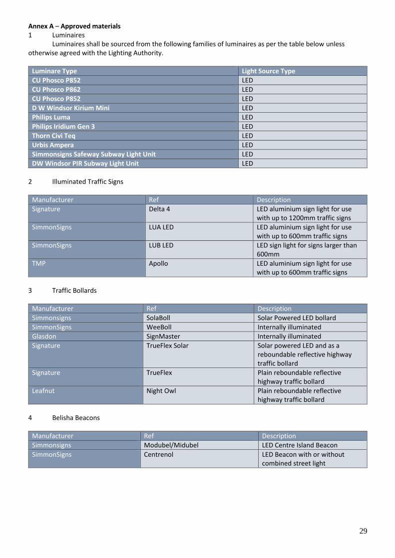
Annex A – Approved materials 1 Luminaires
Luminaires shall be sourced from the following families of luminaires as per the table below unless otherwise agreed with the Lighting Authority. Luminaire Type Light Source Type
Luminare Type Light Source Type
CU Phosco P852 LED
CU Phosco P862 LED
CU Phosco P852 LED
D W Windsor Kirium Mini LED
Philips Luma LED
Philips Iridium Gen 3 LED
Thorn Civi Teq LED
Urbis Ampera LED
Simmonsigns Safeway Subway Light Unit LED
DW Windsor PIR Subway Light Unit LED
2 Illuminated Traffic Signs
Manufacturer Ref Description
Signature Delta 4 LED aluminium sign light for use with up to 1200mm traffic signs
SimmonSigns LUA LED LED aluminium sign light for use with up to 600mm traffic signs
SimmonSigns LUB LED LED sign light for signs larger than 600mm
TMP Apollo LED aluminium sign light for use with up to 600mm traffic signs
Signature 3 Traffic Bollards
Manufacturer Ref Description
Simmonsigns SolaBoll Solar Powered LED bollard
SimmonSigns WeeBoll Internally illuminated
Glasdon SignMaster Internally illuminated
Signature TrueFlex Solar Solar powered LED and as a reboundable reflective highway traffic bollard
Signature TrueFlex Plain reboundable reflective highway traffic bollard
Leafnut Night Owl Plain reboundable reflective highway traffic bollard
mmonsigns 4 Belisha Beacons Manufacturer Ref Description
Manufacturer Ref Description
Simmonsigns Modubel/Midubel LED Centre Island Beacon
SimmonSigns Centrenol LED Beacon with or without combined street light
30
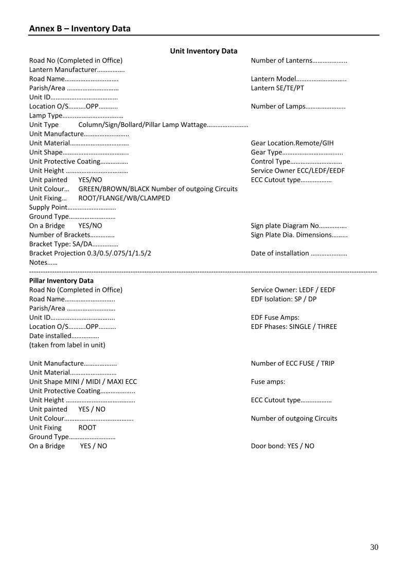
Annex B – Inventory Data
Unit Inventory Data
Road No (Completed in Office) Number of Lanterns……………….. Lantern Manufacturer……………. Road Name…………………………. Lantern Model……………………….. Parish/Area ………………………… Lantern SE/TE/PT Unit ID………………………………… Location O/S……….OPP……….. Number of Lamps………………….. Lamp Type……..……………………… Unit Type Column/Sign/Bollard/Pillar Lamp Wattage…………………… Unit Manufacture…………………….. Unit Material……………………………. Gear Location.Remote/GIH Unit Shape……………………………….. Gear Type…………………………….. Unit Protective Coating……………. Control Type………………………… Unit Height ……………………………… Service Owner ECC/LEDF/EEDF Unit painted YES/NO ECC Cutout type……………… Unit Colour… GREEN/BROWN/BLACK Number of outgoing Circuits Unit Fixing… ROOT/FLANGE/WB/CLAMPED Supply Point………………………. Ground Type……………………… On a Bridge YES/NO Sign plate Diagram No……………. Number of Brackets………….. Sign Plate Dia. Dimensions……... Bracket Type: SA/DA…………… Bracket Projection 0.3/0.5/.075/1/1.5/2 Date of installation ………………… Notes…… ------------------------------------------------------------------------------------------------------------------------------------------------------- Pillar Inventory Data Road No (Completed in Office) Service Owner: LEDF / EEDF Road Name……………………….. EDF Isolation: SP / DP Parish/Area ………………………. Unit ID…………………………….... EDF Fuse Amps: Location O/S……….OPP………. EDF Phases: SINGLE / THREE Date installed……………. (taken from label in unit) Unit Manufacture………………. Number of ECC FUSE / TRIP Unit Material……………………… Unit Shape MINI / MIDI / MAXI ECC Fuse amps: Unit Protective Coating……………….. Unit Height …………………………………. ECC Cutout type……………… Unit painted YES / NO Unit Colour…………………………………. Number of outgoing Circuits Unit Fixing ROOT Ground Type……………………… On a Bridge YES / NO Door bond: YES / NO