Embed Size (px)
Citation preview

4/1
4 - Ultrasonic sensors
Selection guide . . . . . . . . . . . . . . . . . . . . . . . . . . . . . . . . . . . . . . . . . . . . . page 4/2
General . . . . . . . . . . . . . . . . . . . . . . . . . . . . . . . . . . . . . . . . . . . . . . . . . . page 4/4
Osisonic®, Optimum, Universal and applicationSensors with solid-state digital output
Cylindrical type Ø 12, Ø 18 and Ø 30 . . . . . . . . . . . . . . . . . . . . . . . . . page 4/10Flat form . . . . . . . . . . . . . . . . . . . . . . . . . . . . . . . . . . . . . . . . . . . . . . . page 4/16
Sensors with analogue output
Cylindrical type and fl at form . . . . . . . . . . . . . . . . . . . . . . . . . . . . . . . page 4/20
Sensors for monitoring 2 levels
Cylindrical type Ø 18 and Ø 30 . . . . . . . . . . . . . . . . . . . . . . . . . . . . . . page 4/24
b
b
v
v
b
v
b
v
Contents
1
2
3
4
5
6
7
8
9
10
1
2
3
4
5
6
7
8
9
10
1
2
3
4
5
6
7
8
9
10

4/2
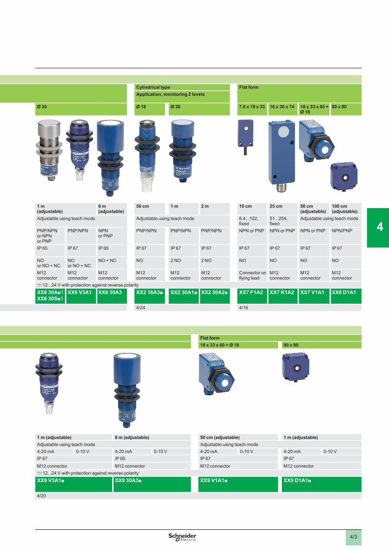
ApplicationsDetection of any object without physical contact, irrespective of:� �aterial ��etal, plastic, woo�, car�boar�, �aterial ��etal, plastic, woo�, car�boar�,�aterial ��etal, plastic, woo�, car�boar�, etc.), nature �soli�, liqui�, pow�er, etc.), colour, �egree of transparency, etc.
Sensors with soli�-state �igital outputCylin�rical type Cylin�rical type Flat for�
Application, �onitoring 2 levels
Di�ensions ���) Ø 12 Ø 18 Ø 30 Ø 18 Ø 30 7.6 x 19 x 33 16 x 30 x 74 18 x 33 x 60 + Ø 18
80 x 80
Sensing �istance Sn 5 c� 10 c� 15 c� 50 c� �a�justable)
1 � �a�justable)
8 � �a�justable)
50 c� 1 � 2 � 10 c� 25 c� 50 c� �a�justable)
100 c� �a�justable)
Sensing range ���) 6.4...51, fixed 6.4...102, fixed 25...152, fixed Adjustable using teach mode Adjustable using teach mode Adjustable using teach mode 6.4...102, fixed
51...254, fixed
Adjustable using teach mode
Type of output PNP/NPN NPN or PNP PNP/NPN NPN or PNP PNP/NPN or NPN or PNP
PNP/NPN
NPN or PNP
PNP/NPN PNP/NPN PNP/NPN NPN or PNP NPN or PNP NPN or PNP NPN/PNP
Degree of protection IP 67 IP 67 IP 67 IP 67 IP 65 IP 67 IP 65 IP 67 IP 67 IP 67 IP 67 IP 67 IP 67 IP 67
Function NO NO NO NO NO or NO + NC
NO or NO + NC
NO + NC NO 2 NO 2 NO NO NO NO NO
Connection M8 connector M8 connector M12 connector M12 connector or pre-cabled M12 connector
M12 connector
M12 connector
M12 connector
M12 connector
M12 connector
Connector on flying lead
M12 connector
M12 connector
M12 connector
Power supply c 12...24 V with protection against reverse polarity c 12...24 V with protection against reverse polaritySensor type XX5 12A1p XX5 12A2p XX5 18A1p XX5 18A3p
XX5 18A3ppL2XX6 30Ap1 XX6 30Sp1
XX6 V3A1 XX6 30A3 XX2 18A3p XX2 30A1p XX2 30A2p XX7 F1A2 XX7 K1A2 XX7 V1A1 XX8 D1A1
Pages 4/10 4/24 4/16
Sensors with analogue outputCylin�rical type Flat for�
Di�ensions ���) Ø 18 Ø 30 18 x 33 x 60 + Ø 18 80 x 80
Sensing �istance Sn 50 c� �a�justable) 1 � �a�justable) 1 � �a�justable) 8 � �a�justable) 50 c� �a�justable) 1 � �a�justable)Sensing range ���) Adjustable using teach mode Adjustable using teach mode Adjustable using teach mode Adjustable using teach modeType of output 4-20 mA/0-10 V 4-20 mA/0-10 V 4-20 mA 0-10 V 4-20 mA 0-10 V 4-20 mA 0-10 V 4-20 mA 0-10 VDegree of protection IP 67 IP 65 IP 67 IP 65 IP 67 IP 67Connection M12 connector M12 connector M12 connector M12 connector M12 connector M12 connectorPower supply c 12...24 V with protection against reverse polarity c 12...24 V with protection against reverse polaritySensor type XX9 18A3p XX9 30A1p
XX9 30S1p
XX9 V3A1p XX9 30A3p XX9 V1A1p XX9 D1A1p
Pages 4/20 4/20
Selection guide Ultrasonic sensorsOsisonic®, Optimum, Universal and Application
1
2
3
4
5
6
7
8
9
10
1
2
3
4
5
6
7
8
9
10
4/3
ApplicationsDetection of any object without physical contact, irrespective of:� �aterial ��etal, plastic, woo�, car�boar�, �aterial ��etal, plastic, woo�, car�boar�,�aterial ��etal, plastic, woo�, car�boar�, etc.), nature �soli�, liqui�, pow�er, etc.), colour, �egree of transparency, etc.
Sensors with soli�-state �igital outputCylin�rical type Cylin�rical type Flat for�
Application, �onitoring 2 levels
Di�ensions ���) Ø 12 Ø 18 Ø 30 Ø 18 Ø 30 7.6 x 19 x 33 16 x 30 x 74 18 x 33 x 60 + Ø 18
80 x 80
Sensing �istance Sn 5 c� 10 c� 15 c� 50 c� �a�justable)
1 � �a�justable)
8 � �a�justable)
50 c� 1 � 2 � 10 c� 25 c� 50 c� �a�justable)
100 c� �a�justable)
Sensing range ���) 6.4...51, fixed 6.4...102, fixed 25...152, fixed Adjustable using teach mode Adjustable using teach mode Adjustable using teach mode 6.4...102, fixed
51...254, fixed
Adjustable using teach mode
Type of output PNP/NPN NPN or PNP PNP/NPN NPN or PNP PNP/NPN or NPN or PNP
PNP/NPN
NPN or PNP
PNP/NPN PNP/NPN PNP/NPN NPN or PNP NPN or PNP NPN or PNP NPN/PNP
Degree of protection IP 67 IP 67 IP 67 IP 67 IP 65 IP 67 IP 65 IP 67 IP 67 IP 67 IP 67 IP 67 IP 67 IP 67
Function NO NO NO NO NO or NO + NC
NO or NO + NC
NO + NC NO 2 NO 2 NO NO NO NO NO
Connection M8 connector M8 connector M12 connector M12 connector or pre-cabled M12 connector
M12 connector
M12 connector
M12 connector
M12 connector
M12 connector
Connector on flying lead
M12 connector
M12 connector
M12 connector
Power supply c 12...24 V with protection against reverse polarity c 12...24 V with protection against reverse polaritySensor type XX5 12A1p XX5 12A2p XX5 18A1p XX5 18A3p
XX5 18A3ppL2XX6 30Ap1 XX6 30Sp1
XX6 V3A1 XX6 30A3 XX2 18A3p XX2 30A1p XX2 30A2p XX7 F1A2 XX7 K1A2 XX7 V1A1 XX8 D1A1
Pages 4/10 4/24 4/16
Sensors with analogue outputCylin�rical type Flat for�
Di�ensions ���) Ø 18 Ø 30 18 x 33 x 60 + Ø 18 80 x 80
Sensing �istance Sn 50 c� �a�justable) 1 � �a�justable) 1 � �a�justable) 8 � �a�justable) 50 c� �a�justable) 1 � �a�justable)Sensing range ���) Adjustable using teach mode Adjustable using teach mode Adjustable using teach mode Adjustable using teach modeType of output 4-20 mA/0-10 V 4-20 mA/0-10 V 4-20 mA 0-10 V 4-20 mA 0-10 V 4-20 mA 0-10 V 4-20 mA 0-10 VDegree of protection IP 67 IP 65 IP 67 IP 65 IP 67 IP 67Connection M12 connector M12 connector M12 connector M12 connector M12 connector M12 connectorPower supply c 12...24 V with protection against reverse polarity c 12...24 V with protection against reverse polaritySensor type XX9 18A3p XX9 30A1p
XX9 30S1p
XX9 V3A1p XX9 30A3p XX9 V1A1p XX9 D1A1p
Pages 4/20 4/20
1
2
3
4
5
6
7
8
9
10
1
2
3
4
5
6
7
8
9
10
4/4
1
2
3
4
5
6
7
8
9
10
1
2
3
4
5
6
7
8
9
10
Ultrasonic sensors 2 Osisonic®
Quality, standards and certifications Quality controlThe Osisonic ultrasonic sensors are subjecte� to special precautions in or�er to guarantee their reliability in the �ost ar�uous in�ustrial environ�ents.
Qualification A qualification procedure on the characteristics of Osisonic ultrasonic sensors is carried out in our laboratories.
Pro�uctionThe electrical characteristics, sensing distances at the ambient temperature and operating
temperatures are 100% verified.Sensors are randomly selected during the course of production and subjected to �onitoring
tests on all qualified characteristics.
Custo�er returnsDefective ultrasonic sensors are subjected to systematic analysis and corrective actions are implemented to eliminate recurrence of the fault.
b
bv
v
b
Confor�ity to stan�ar�sThe Osisonic ultrasonic sensors conform to the standards IEC 60947-5-2.Standards and characteristics: refer to page 4/11.
Resistance to che�icals in the environ�entTo ensure lasting efficient operation, it is essential that any chemicals coming into contact with the ultrasonic sensors will not affect their casing and, in doing so, prevent their reliable operation.
Due to the materials used, Osisonic ultrasonic sensors are very resistant to:
chemical agents:salts, aliphatic and aromatic oils,petroleum, diluted bases and acids.
Depending on their nature and concentration, tests should be carried out beforehand for the following chemical agents:
alcohols, ketones and phenols.
food and beverage industry products:vegetable oils, animal fats, fruit juices, milk proteins, etc.
bvv
v
bvvv
Resistance to the environ�entIP 65: protection against water jets. Test according to IEC 60529: the device is subjected to water sprayed from a Ø 6,3 mm nozzle, at a flow rate of 12,5 litres/min for 3 min at a distance of 3 m. No deterioration in either operating or insulation characteristics is permitted.
IP 67: protection against the effects of immersion. Tested in accordance with IEC 60529: sensor immersed for 30 minutes in 1 m of water. No deterioration in either operating or insulation characteristics is permitted.
b
b
General 2

4/5
1
2
3
4
5
6
7
8
9
10
1
2
3
4
5
6
7
8
9
10
Ultrasonic sensors 2 Osisonic®
Reco��en�ationsThe ultrasonic sensors are designed for use in standard industrial applications involving presence detection.Since these sensors do not incorporate a redundant electrical circuit, they are not suitable for use in safety applications.For safety applications, please refer to our “Safety solutions using Preventa” catalogue.
Principle of ultrasonic �etection PresentationUltrasonic sensors enable detection, without contact, of any object irrespective of its:
material (metal, plastic, wood, cardboard, etc.),nature (solid, liquid, powder, etc.),colour,degree of transparency.
They are used in industrial applications for detecting, for example: the position of machine parts,the presence of the windscreen during automobile assembly,the flow of objects on a conveyor system: glass bottles, cardboard packages, cakes, etc.,the level
of different colour paints in pots,of plastic pellets in injection moulding machine feeders.
The ultrasonic sensors are simple to install due to their integral connector and availability of cabling and fixing accessories.
bbbb
bbbb--
Operating principle The principle of ultrasonic detection is based on measuring the time taken between transmission
of an ultrasonic wave (pressure wave) and reception of its echo (return of transmitted wave).
Osisonic ultrasonic sensors are of the cylindrical type. They comprise:1 high voltage generator2 piezoelectric transducer (transmitter and receiver)3 signal processing stage4 output stage
Excited by the high voltage generator 1, the transducer (transmitter-receiver) 2 generates a pulsed ultrasonic wave (200 to 500 kHz depending on the product) which travels through the ambient air at the speed of sound. When the wave strikes an object, it reflects (echo) and travels back towards the transducer. A micro controller 3 analyses the signal received and measures the time interval between the transmitted signal and the echo. By comparison with the preset or learnt times, it determines and controls the output states 4.The output stage 4 controls a solid-state switch (PNP or NPN transistor) corresponding to a NO or NC contact (detection of object).
A�vantages of ultrasonic �etectionNo physical contact with the object to be detected, therefore, no wear and detection possible
of fragile or freshly painted objects, etc.Detection of any material, irrespective of colour, at the same distance, without adjustment or
correction factor.Teach mode function, by simply pressing a button, for defining the effective sensing range.
Teach of the minimum and maximum sensing distances (very precise foreground and background suppression, ± 6 mm).
Very good resistance to industrial environments (robust products entirely encapsulated in resin).
Solid-state units: no moving parts in the sensor, therefore, service life independent of the number of operating cycles.
b
b
b
b
b
1
2
34
1
2
34
TargetTarget
General (continued) 2

4/6
1
2
3
4
5
6
7
8
9
10
1
2
3
4
5
6
7
8
9
10
Ultrasonic sensors 2 Osisonic®
Ter�inology DefinitionsThe terms listed below are defined by the standard IEC 60947-5-2:
Nominal sensing distance (Sn) Conventional value for indicating the sensing distance. It does not take into account manufacturing tolerances nor variations caused by external conditions such as voltage and temperature.
Sensing range (Sd)Zone in which the sensor is sensitive to objects.
Minimum sensing distanceLower limit of the specified sensing range.
Maximum sensing distanceUpper limit of the specified sensing range.
Assured operating distance (Sa)This corresponds to the operating zone of the sensor (activation of outputs), and is included in the sensing range. Its limits are fixed:
at the factory for fixed sensing distance sensors,when setting-up within the application for sensors with teach mode.
Blind zoneZone between the sensing face of the sensor and the minimum sensing distance in which no object can be reliably detected.Avoid any passing of objects in this blind zone during operation of the sensor. This could lead to instability of the output states.
Differential travel The differential travel (H) or hysteresis is the distance between the pick-up point as the standard metal target moves towards the sensor and the drop-out point as it moves away from the sensor.
Repeat accuracyThe repeat accuracy (R) is the precision of reproduction between two successive measurements of the sensing distance, made in identical conditions.
Overall beam angleSolid angle around the reference axis of an ultrasonic proximity sensor.
Standard targetThe standard IEC 60947-5-2 defines the standard target as a square metal plate, 1 mm thick with rolled finish, placed perpendicularly to the reference axis.Its side dimension depends on the sensing range:
b
b
b
b
b
--
b
b
b
b
b
Sensing range (mm) Size of target (mm)
< 300 10 x 10
300 < d < 800 20 x 20
> 800 100 x 100
Voltage drop (Ud)The voltage drop (Ud) corresponds to the voltage at the terminals of the sensor when in the closed state (value measured at the nominal current of the sensor).
b
First-up delayTime required to ensure operation of the sensor’s output signal following power-up.1 Power-up2 Output signal state (0 or 1)
b
Response timeResponse time (Ra): time taken between the instant the object to be detected enters the active
zone and the changing of the output signal state. This time limits the passing speed of the target in relation to its dimensions.
Recovery time (Rr): time taken between the object being detected leaving the active zone and the changing of the output signal state. This time limits the interval between 2 objects.
bv
v
Sn
Blind zone Sensing range (Sd)
Overall beam angle
Standard metal target
Minimum sensing distance
Assured operating distance (Sa)
Maximum sensing distance
Reference axis
Sn
Blind zone Sensing range (Sd)
Overall beam angle
Standard metal target
Minimum sensing distance
Assured operating distance (Sa)
Maximum sensing distance
Reference axis
H
PR PE
Frontal approach
Sensing distance
PR PE
PR = drop-out pointPE = pick-up point
H
PR PE
Frontal approach
Sensing distance
PR PE
PR = drop-out pointPE = pick-up point
UdV
UdV
t
1
2
1 2
Sensor output
Supply
t
1
2
1 2
Sensor output
Supply
Ra Rr
Object to be detected
Sensor output
Ra Rr
Object to be detected
Sensor output
General (continued) 2
4/7
1
2
3
4
5
6
7
8
9
10
1
2
3
4
5
6
7
8
9
10
Ultrasonic sensors 2 Osisonic®
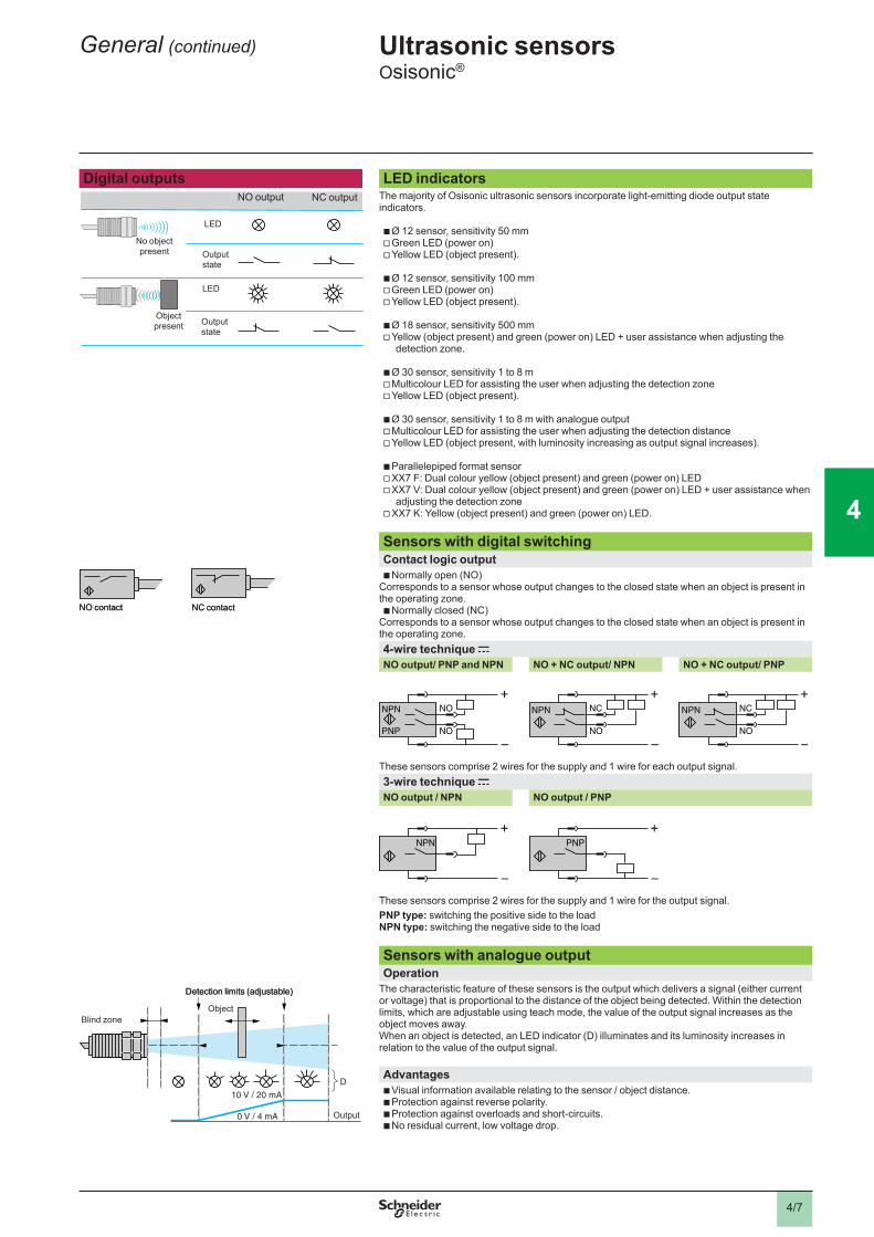
Digital outputs LED in�icatorsThe majority of Osisonic ultrasonic sensors incorporate light-emitting diode output state indicators.
Ø 12 sensor, sensitivity 50 mmGreen LED (power on)Yellow LED (object present).
Ø 12 sensor, sensitivity 100 mmGreen LED (power on)Yellow LED (object present).
Ø 18 sensor, sensitivity 500 mmYellow (object present) and green (power on) LED + user assistance when adjusting the detection zone.
Ø 30 sensor, sensitivity 1 to 8 mMulticolour LED for assisting the user when adjusting the detection zoneYellow LED (object present).
Ø 30 sensor, sensitivity 1 to 8 m with analogue outputMulticolour LED for assisting the user when adjusting the detection distanceYellow LED (object present, with luminosity increasing as output signal increases).
Parallelepiped format sensorXX7 F: Dual colour yellow (object present) and green (power on) LEDXX7 V: Dual colour yellow (object present) and green (power on) LED + user assistance when adjusting the detection zone
XX7 K: Yellow (object present) and green (power on) LED.
bvv
bvv
bv
bvv
bvv
bvv
v
Sensors with �igital switching Contact logic output
Normally open (NO)Corresponds to a sensor whose output changes to the closed state when an object is present in the operating zone.
Normally closed (NC)Corresponds to a sensor whose output changes to the closed state when an object is present in the operating zone.
b
b
4-wire technique cNO output/ PNP an� NPN NO + NC output/ NPN NO + NC output/ PNP
These sensors comprise 2 wires for the supply and 1 wire for each output signal.3-wire technique cNO output / NPN NO output / PNP
These sensors comprise 2 wires for the supply and 1 wire for the output signal.PNP type:� switching the positive side to the loadNPN type:� switching the negative side to the load
Sensors with analogue output Operation
The characteristic feature of these sensors is the output which delivers a signal (either current or voltage) that is proportional to the distance of the object being detected. Within the detection limits, which are adjustable using teach mode, the value of the output signal increases as the object moves away.When an object is detected, an LED indicator (D) illuminates and its luminosity increases in relation to the value of the output signal.
A�vantagesVisual information available relating to the sensor / object distance.Protection against reverse polarity.Protection against overloads and short-circuits.No residual current, low voltage drop.
bbbb
LED
Outputstate
LED
Outputstate
Object present
NO output
No object present
NC output
LED
Outputstate
LED
Outputstate
Object present
NO output
No object present
NC output
NC contactNO contact NC contactNO contact
+
–
NPN
PNP
NO
NO
+
–
NPN
PNP
NO
NO
+
–
NPN NC
NO
+
–
NPN NC
NO
+
–
NPN NC
NO
+
–
NPN NC
NO
+
–
NPN
+
–
NPN
+
–
PNP
+
–
PNP
10 V / 20 mA
0 V / 4 mA
D
Blind zone
Output
Detection limits (adjustable)
Object
10 V / 20 mA
0 V / 4 mA
D
Blind zone
Output
Detection limits (adjustable)
Object
General (continued) 2

4/8
1
2
3
4
5
6
7
8
9
10
1
2
3
4
5
6
7
8
9
10
Ultrasonic sensors 2 Osisonic®
Power supply �.c. sourceCheck that the voltage limits of the sensor and the acceptable level of ripple, are compatible with the supply used.
a.c. source (comprising transformer, rectifier, smoothing capacitor)The supply voltage must be within the operating limits specified for the sensor. Where the voltage is derived from a single phase a.c. supply, the voltage must be rectified and smoothed to ensure that:
the peak voltage of the d.c. supply is lower than the maximum voltage rating of the sensor. Peak voltage = nominal voltage x √2
the minimum voltage of the d.c. supply is greater than the minimum voltage rating of the sensor, given that: DV = (I x t) / C DV = maximum ripple: 10 % (V), I = anticipated load current (mA), t = period of 1 cycle (10 ms full-wave rectified for a 50 Hz supply frequency), C = capacitance (µF). As a general rule, use a transformer with a lower secondary voltage (Ue) than the required d.c. voltage (U). Exa�ple:� a 18 V to obtain c 24 V.
b
b
Setting-up precautions MountingMounting �istance between ultrasonic sensors
If 2 standard sensors are mounted too close to each other, the wave transmitted by one sensor is likely to interfere with the other and result in erratic operation. In order to avoid this, it is necessary to adhere to the minimum distances between sensors.
Maxi�u� tightening torque Cylin�rical sensor
Dia�eter ��
Tightening torque
Flat for� sensors
Screw Tightening torque
XX5 12p Ø 12 0,7 N.m XX7 Fp M3 0,7 N.mXX5 18p Ø 18 1 N.m XX7 Kp M4 1 N.mXX6 30p Ø 30 1,35 N.m XX7 Vp M3 0,7 N.m
Ø 18 1 N.m
InterchangeabilityUsing the indexed fixing clamp, the assembly is similar to a block type sensor.
CablingElectrical connection
Connect the sensor before switching on the supply
Length of cableNo limitation up to 200 m or up to a line capacitance of < 0.1 mF (characteristics of sensor
remain unaffected).It is, however, advisable to take into account the voltage drop on the line.
Separation of control an� power cablesThe sensors are immune to electrical interference encountered in normal industrial
conditions.Where extreme conditions of electrical “noise” could occur (large motors, spot welders, etc.),
it is advisable to protect against transients in the normal way:suppress interference at source,separate power and control wiring from each other,smooth the supply,limit the length of cable.
b
bv
v
bv
v
----
e
e
Mounting side by sidee u Sn
Mounting face to facee u 4 Sn max.
e
e
Mounting side by sidee u Sn
Mounting face to facee u 4 Sn max.
General (continued) 2

4/9
1
2
3
4
5
6
7
8
9
10
1
2
3
4
5
6
7
8
9
10
Ultrasonic sensors 2 Osisonic®
Setting-up precautions (continued) Connection in seriesThis connection �etho� is not reco��en�e�.
Correct operation of the sensors cannot be assured and, if this method is used, tests must be made before installation. The following points should be taken into account:
Sensor 1 carries the load current in addition to the no-load current consumption values of the other sensors connected in series. For certain models, this connection method is not possible unless a current limiting resistor is used.
When in the closed state, each sensor will produce a voltage drop and, therefore, the load voltage should be selected accordingly.
As sensor 1 closes, sensor 2 will not operate until a certain time “T” has elapsed (corresponding to the first-up delay) and likewise for the following sensors in the sequence.
“Flywheel” diodes should be used when the load being switched is inductive.
b
v
v
v
v
Sensors an� units in series with an external �echanical contactThe following points should be taken into account:When the mechanical contact is open, the sensor is not supplied.When the contact closes, the sensor will not operate until a certain time “T” has elapsed
(corresponding to the first-up delay).
bvv
Connection in parallel
No specific restrictions. The use of “flywheel” diodes is recommended when an inductive load (relay) is being switched.b
Capacitive loa� �C > 0.1 mF)At switch-on, it is necessary to limit (by resistor) the charging current of the capacitive load C.The voltage drop in the sensor can also be taken into account by subtracting it from the
supply voltage for the calculation of R.
R = U (supply)I max. (sensor)
bv
Loa� co�prising an incan�escent la�pIf the load comprises an incandescent lamp, the cold state resistance can be 10 times lower
than the hot state resistance. This can cause very high current levels on switching. Fit a pre-heat resistance in parallel with the sensor.
R = U2
Px 10 , U = supply voltage and P = lamp power
b
Detection Influencing factors
The ultrasonic sensors are particularly suited to the detection of a hard object with a flat surface perpendicular to the detection axis.
However, the correct operation of the ultrasonic sensor can be disrupted by: air currents, which can accelerate or divert the acoustic wave transmitted by the sensor
(ejection of part by air jet),high temperature gradients within the sensing range: an object emitting considerable heat can
create zones of varying temperature that will modify the propagation time of the wave and thus prevent reliable operation,
sound insulators: sound absorbing materials (cotton, fabrics, rubber, etc.),the angle between the face of the object to be detected and the reference axis of the sensor:
when the angle is offset from 90°, the wave is no longer reflected back along the sensor axis and the operating distance is reduced. The greater the distance between the sensor and the target, the greater the effect. Detection is not possible when the angle exceeds ± 10°.
the shape of the object to be detected: similar to the example above, an excessively angular object can be difficult to detect 1.
Detection by beam break (reflex system)In cases requiring detection of sound insulating materials, angular objects, or an angle exists between the face of the object to be detected and the reference axis of the sensor, it is recommended that a sensor with the teach mode feature be selected, which enables beam break detection using a reflector. This reflector can be any flat, hard and fixed part of the machine 2.The sensor with the teach mode feature can also be used in confined spaces by using a 90° reflector. In the same manner as for the return reflector, the 90° reflector can be a flat part of the machine 3.It is also possible to use beam break detection (reflex system) with the 90° reflector 4.
Caution:� in reflex mode, the NO function opens when an object is present and the NC function closes when an object is present.
b
v
v
vv
v
b
Sensor 1
Sensor 2
Sensor 3
Sensor 1
Sensor 2
Sensor 3
– R
– C
– R
– C
11
2
Reflector
2
Reflector
3
4
Target
Reflector
3
4
Target
Reflector
General (continued) 2
4/10
1
2
3
4
5
6
7
8
9
10
1
2
3
4
5
6
7
8
9
10
References
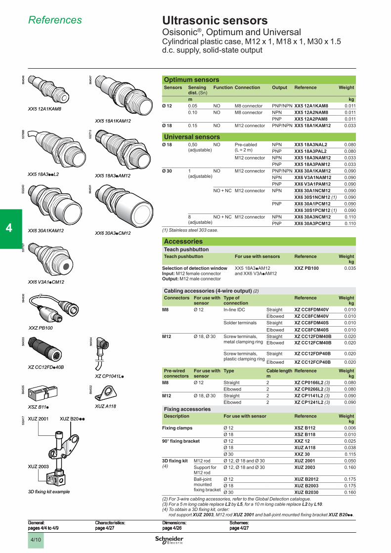
Optimum sensorsSensors Sensing
dist. (Sn)Function Connection Output Reference Weight
m kgØ 12 0.05 NO M8 connector PNP/NPN XX5 12A1KAM8 0.011
0.10 NO M8 connector NPN XX5 12A2NAM8 0.011PNP XX5 12A2PAM8 0.011
Ø 18 0.15 NO M12 connector PNP/NPN XX5 18A1KAM12 0.033
Universal sensorsØ 18 0,50
(adjustable)NO Pre-cabled
(L = 2 m)NPN XX5 18A3NAL2 0.080PNP XX5 18A3PAL2 0.080
M12 connector NPN XX5 18A3NAM12 0.033PNP XX5 18A3PAM12 0.033
Ø 30 1 (adjustable)
NO M12 connector PNP/NPN XX6 30A1KAM12 0.090NPN XX6 V3A1NAM12 0.090PNP XX6 V3A1PAM12 0.090
NO + NC M12 connector NPN XX6 30A1NCM12 0.090XX6 30S1NCM12 (1) 0.090
PNP XX6 30A1PCM12 0.090XX6 30S1PCM12 (1) 0.090
8 (adjustable)
NO + NC M12 connector NPN XX6 30A3NCM12 0.110PNP XX6 30A3PCM12 0.110
(1) Stainless steel 303 case.
AccessoriesTeach pushbuttonTeach pushbutton For use with sensors Reference Weight
kgSelection of detection windowInput:� M12 female connectorOutput: M12 male connector
XX5 18A3pAM12 and XX6 V3ApAM12
XXZ PB100 0.035
Cabling accessories (4-wire output) (2)
Connectors
For use with sensor
Type of connection
Reference Weight kg
M8 Ø 12 In-line IDC Straight XZ CC8FDM40V 0.010Elbowed XZ CC8FCM40V 0.010
Solder terminals Straight XZ CC8FDM40S 0.010Elbowed XZ CC8FCM40S 0.010
M12 Ø 18, Ø 30 Screw terminals, metal clamping ring
Straight XZ CC12FDM40B 0.020Elbowed XZ CC12FCM40B 0.020
Screw terminals, plastic clamping ring
Straight XZ CC12FDP40B 0.020
Elbowed XZ CC12FCP40B 0.020
Pre-wired connectors
For use with sensor
Type Cable lengthm
Reference Weight kg
M8 Ø 12 Straight 2 XZ CP0166L2 (3) 0.080Elbowed 2 XZ CP0266L2 (3) 0.080
M12 Ø 18, Ø 30 Straight 2 XZ CP1141L2 (3) 0.090Elbowed 2 XZ CP1241L2 (3) 0.090
Fixing accessories Description For use with sensor Reference Weight
kgFixing clamps Ø 12 XSZ B112 0.006
Ø 18 XSZ B118 0.01090° fixing bracket Ø 12 XXZ 12 0.025
Ø 18 XUZ A118 0.038Ø 30 XXZ 30 0.115
3D fixing kit (4)
M12 rod Ø 12, Ø 18 and Ø 30 XUZ 2001 0.050Support for M12 rod
Ø 12, Ø 18 and Ø 30 XUZ 2003 0.160
Ball-joint mounted fixing bracket
Ø 12 XUZ B2012 0.175Ø 18 XUZ B2003 0.175Ø 30 XUZ B2030 0.160
(2) For 3-wire cabling accessories, refer to the Global Detection catalogue.(3) For a 5 m long cable replace L2 by L5, for a 10 m long cable replace L2 by L10.(4)Toobtaina3Dfixingkit,order:
rod support XUZ2003, M12 rod XUZ2001andball-jointmountedfixingbracketXUZB20pp.
XX5 12A1KAM8
XZ CC12FDp40B
XZ CP1041Lp
5645
46
XXZ PB100
5645
30
5645
47
XX5 18A1KAM12
XX5 18A3ppL2
5376
88
XX5 18A3pAM12
5327
13
5322
43
XX6 30A1KAM12
5645
31
XX6 30A3pCM12
5645
33
5645
34
5645
35
5645
32
XSZ B11p XUZ A118
5324
17
3Dfixingkitexample
5377
27
XX6 V3A1pCM12
XUZ 2003
XUZ 2001 B20XUZ
XX5 12A1KAM8
XZ CC12FDp40B
XZ CP1041Lp
5645
46
XXZ PB100
5645
30
5645
47
XX5 18A1KAM12
XX5 18A3ppL2
5376
88
XX5 18A3pAM12
5327
13
5322
43
XX6 30A1KAM12
5645
31
XX6 30A3pCM12
5645
33
5645
34
5645
35
5645
32
XSZ B11p XUZ A118
5324
17
3Dfixingkitexample
5377
27
XX6 V3A1pCM12
XUZ 2003
XUZ 2001 B20XUZ
General:pages 4/4 to 4/9
Characteristics:page 4/27
Dimensions:page 4/26
Schemes:page 4/27
General:pages 4/4 to 4/9
Characteristics:page 4/27
Dimensions:page 4/26
Schemes:page 4/27
General:pages 4/4 to 4/9
Characteristics:page 4/27
Dimensions:page 4/26
Schemes:page 4/27
General:pages 4/4 to 4/9
Characteristics:page 4/27
Dimensions:page 4/26
Schemes:page 4/27
Ultrasonic sensorsOsisonic®, Optimum and UniversalCylindrical plastic case, M12 x 1, M18 x 1, M30 x 1.5d.c. supply, solid-state output

4/11
1
2
3
4
5
6
7
8
9
10
1
2
3
4
5
6
7
8
9
10
Characteristics, setting-up
Sensor type XX5 12A1pppp
XX5 12A2pppp
XX5 18A1pppp
XX5 18A3pM12
XX5 18A3ppL2
XX6 V3A1pppp
XX6 30A1pppp30S1pppp
XX6 30A3pppp
CharacteristicsProduct certifications e
Conformity to standards IEC 60947-5-2, UL508 pending and CSA C22-2 n° 14 pendingConnection Connector M8, 4-pin M8, 3-pin M12, 4-pin M12, 4-pin – M12, 4-pin M12, 4-pin M12, 4-pin
Pre-cabled – – – – L = 2 m 4 x 0.008 mm2
– – –
Sensing range mm 6.4…51 6.4…102 19…152 51…508 51…508 100...1000 51…991 203…8000Nominal sensing distance (Sn) m 0.05 0.1 0.15 0.50 0.50 1 1 8Detection distance mm Fixed Remotely adjustable using external
teach buttonAdjustable using teach button on sensor
Blind zone (no object must pass through this zone whilst the sensor is operating)
mm 0…6.4 0…6.4 0…19 0…51 0…51 0...100 0…51 0…203
Differential travel mm < 0.7 < 0.7 < 0.35 < 2.5 < 2.5 < 2.5 < 2.5 < 12.7Transmission frequency kHz 500 300 300 180 200 75Repeat accuracy mm ± 0.7 ± 1.27 ± 1.27 ± 1.6 ± 0.9 ± 2.54Overall beam angle (see detection lobe) 11° 10° 8° 6° 6° 7° 10° 16°Minimum size of object to be detected Cylinder Ø 2.5 mm or
flat bar 1 mm wideCylinder Ø 1.6 mm
Cylinder Ø 2.5 mm up to a sensing distance of 150 mm
Cylinder Ø 2.5 mm up to a sensing distance of 150 mm
Cylinder Ø 50 mm up to a sensing distance of 1000 mm
Cylinder Ø 1.6 mm up to a sensing distance of 635 mm
Cylinder Ø 50.8 mm up to a sensing distance of 4732 mm
Degree of protection To IEC 60529 and IEC 60947-5-2
IP 67 IP 67 IP 65 IP 67
Storage temperature °C - 40…+ 80Operating temperature °C - 20…+ 65 0…+ 50 - 20…+ 65 - 20…+ 65 0…+ 70 0…+ 60 - 20…+ 60Materials Case ULTEM® Valox® Valox® Valox® ULTEM® ULTEM®
Stainless steel 303 for XX6 30AS1pppp
Sensing face Epoxy Silicone Epoxy Epoxy Epoxy Silicone EpoxyVibration resistance To IEC 60068-2-6 Amplitude ± 1 mm (f = 10…55 Hz)Mechanical shock resistance
To IEC 60068-2-27 30 gn, duration 11 ms, in all 3 axes
Resistance to electromagnetic interference
Electrostatic discharges To IEC 61000-4-2 kV 8, level 4Radiated electromagnetic fields
To IEC 61000-4-3 V/m 10, level 3
Fast transients To IEC 61000-4-4 kV 1, level 3LED indicators Output state Yellow LED Yellow LED – Yellow LED
Power on Green LED Green LED – Green LED –Setting-up assistance – – – Dual colour LED Multicolour LED
Rated supply voltage V c 12…24 V with protection against reverse polarityVoltage limits (including ripple) V c 10…28 VCurrent consumption, no-load mA 25 60 40 40 60 50 50Switching capacity mA < 100 (PNP and NPN) with overload and short-circuit protectionVoltage drop V < 1 (NPN); < 1.5 (PNP)Maximum switching frequency Hz 125 125 80 40 40 70 10 2Delays First-up ms 20 20 350 100 100 75 720 800
Response ms 2 3 3 10 10 15 20 200Recovery ms 2 3 3 10 10 75 20 200
Deviation angle from 90° of the object to be detected
± 10° ± 10° ± 10° ± 7° ± 7° ± 5° ± 7° ± 5°
Setting-upMinimum mounting distancesSide by side Face to face
e: respect the distances indicated on the detection curves shown on page 4/43.
e = 4 x Sn max.
ee
General:pages 4/4 to 4/9
References:page 4/24
Dimensions:page 4/26
Schemes:page 4/27
General:pages 4/4 to 4/9
References:page 4/24
Dimensions:page 4/26
Schemes:page 4/27
General:pages 4/4 to 4/9
References:page 4/24
Dimensions:page 4/26
Schemes:page 4/27
General:pages 4/4 to 4/9
References:page 4/24
Dimensions:page 4/26
Schemes:page 4/27
Ultrasonic sensorsOsisonic®, Optimum and UniversalCylindrical plastic case, M12 x 1, M18 x 1, M30 x 1.5d.c. supply, solid-state output
4/12
1
2
3
4
5
6
7
8
9
10
1
2
3
4
5
6
7
8
9
10
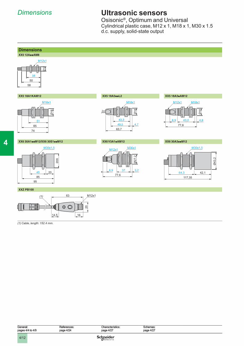
Dimensions
DimensionsXX5 12AppAM8
M12x1
5038
58
XX5 18A1KAM12 XX5 18A3ppL2 XX5 18A3pAM12
65
51
M18x1
74
M18x1
63,7
49,5
43,3
4,7
M18x1
77,6
43,28,9 4,8
M12x1
XX6 30A1ppM12/XX6 30S1ppM12 XX6 V3A1pAM12 XX6 30A3ppM12
8595
45 20
M30x1,5 M30x1
77,6378,9 3,2
M12x1
Ø27
,2
117,35
42,164,3
M30x1,5
Ø43
,2
XXZ PB100
63
1614,5
(1) M12x1
20
(1)Cable,length:152.4mm.
Ultrasonic sensorsOsisonic®, Optimum and UniversalCylindrical plastic case, M12 x 1, M18 x 1, M30 x 1.5d.c. supply, solid-state output
General:pages 4/4 to 4/9
References:page 4/24
Characteristics:page 4/27
Schemes:page 4/27
General:pages 4/4 to 4/9
References:page 4/24
Characteristics:page 4/27
Schemes:page 4/27

4/13
1
2
3
4
5
6
7
8
9
10
1
2
3
4
5
6
7
8
9
10
Dimensions (continued)
DimensionsAccessoriesXUZ A118 XXZ 12, XXZ 30
90° fixing bracket (Ø 18) 90° fixing bracket (Ø 12 and Ø 30)
XXZ a b c c1 e H G G1 Ø Ø112 35 40 33 18 2 31 18 18 25 1330 67 65 52 25 3 51 35 33 50 31
XSZ B112, XSZ B118 XUZ 2001 XUZ 2003Fixing clamps (Ø 12 and Ø 18) M12 rod Support for M12 rod
XSZ a a1 b b1 b2 ØB112 21.9 14.5 16 15.5 8.5 12B118 26 15.7 22,3 20.1 11.5 18(1) 2 elongated holes Ø 4 x 8.XUZ B2012 XUZ B2003 XUZ 2030
Ball-joint mounted fixing bracket (Ø 12) Ball-joint mounted fixing bracket (Ø 18) Ball-joint mounted fixing bracket (Ø 30)
2,5 Ø18,2
35
28
1
15
206,5
6,5
=
10
=
16,5
= =
502,5 Ø18,2
35
28
1
15
206,5
6,5
=
10
=
16,5
= =
50
a
10Ø5Ø1
G1 Ø
G
H
c1
c
e
b
a
10Ø5Ø1
G1 Ø
G
H
c1
c
e
b
4 822,3
(1)
38,3
b
b2
a
3,5
b1
a1
4 822,3
(1)
38,3
b
b2
a
3,5
b1
a1
126
5055
132
40
126
5055
132
40 23
40
M12
1,9
12
19
53
36
1919
23
40
M12
1,9
12
19
53
36
1919
5,7
22,9
40
33
36
76,5
M4
Ø12,4
67
5,7
22,9
40
33
36
76,5
M4
Ø12,4
67
5,7
22,9
40
33
36
76,5
M4
Ø18,5
67
5,7
22,9
40
33
36
76,5
M4
Ø18,5
67
6
22,9
46,324
,1
42,2
90,5
M3
81,7
13
Ø30,56
22,9
46,324
,1
42,2
90,5
M3
81,7
13
Ø30,5
Ultrasonic sensorsOsisonic®, Optimum and UniversalCylindrical plastic case, M12 x 1, M18 x 1, M30 x 1.5d.c. supply, solid-state output
General:pages 4/4 to 4/9
References:page 4/24
Characteristics:page 4/27
Schemes:page 4/27
General:pages 4/4 to 4/9
References:page 4/24
Characteristics:page 4/27
Schemes:page 4/27

4/14
1
2
3
4
5
6
7
8
9
10
1
2
3
4
5
6
7
8
9
10
Curves
Detection curvesXX5 12A1KAM8 XX5 12A2pNAM8 XX5 18A1KAM12
0 10 20 30 40 50 60-20
-10
10
20mm
mm cm2 4 6 8 100
10
-10
20
-20
mm
100 150 200500mm
40
-40
80
-80
mm
XX5 18A3ppL2/XX5 18A3pAM12 XX6 30A1pCM12 XX6 30A3pCM12
65 190 320 445 570mm
0
mm
100
-100
200
-20020 40 60 80 100
cm0
100
200
-100
-200
mm
2 4 6 8 m0
100
-100
200
-200
cm
XX6 V3A1
20 40 60 80 100cm
0
100
200
-100
-200
mm
Blind zone
Ultrasonic sensorsOsisonic®, Optimum and UniversalCylindrical plastic case, M12 x 1, M18 x 1, M30 x 1.5d.c. supply, solid-state output
General:pages 4/4 to 4/9
Characteristicspage 4/27
References:page 4/24
Dimensions:page 4/26
Schemes:page 4/27
General:pages 4/4 to 4/9
Characteristicspage 4/27
References:page 4/24
Dimensions:page 4/26
Schemes:page 4/27
4/15
1
2
3
4
5
6
7
8
9
10
1
2
3
4
5
6
7
8
9
10
Schemes
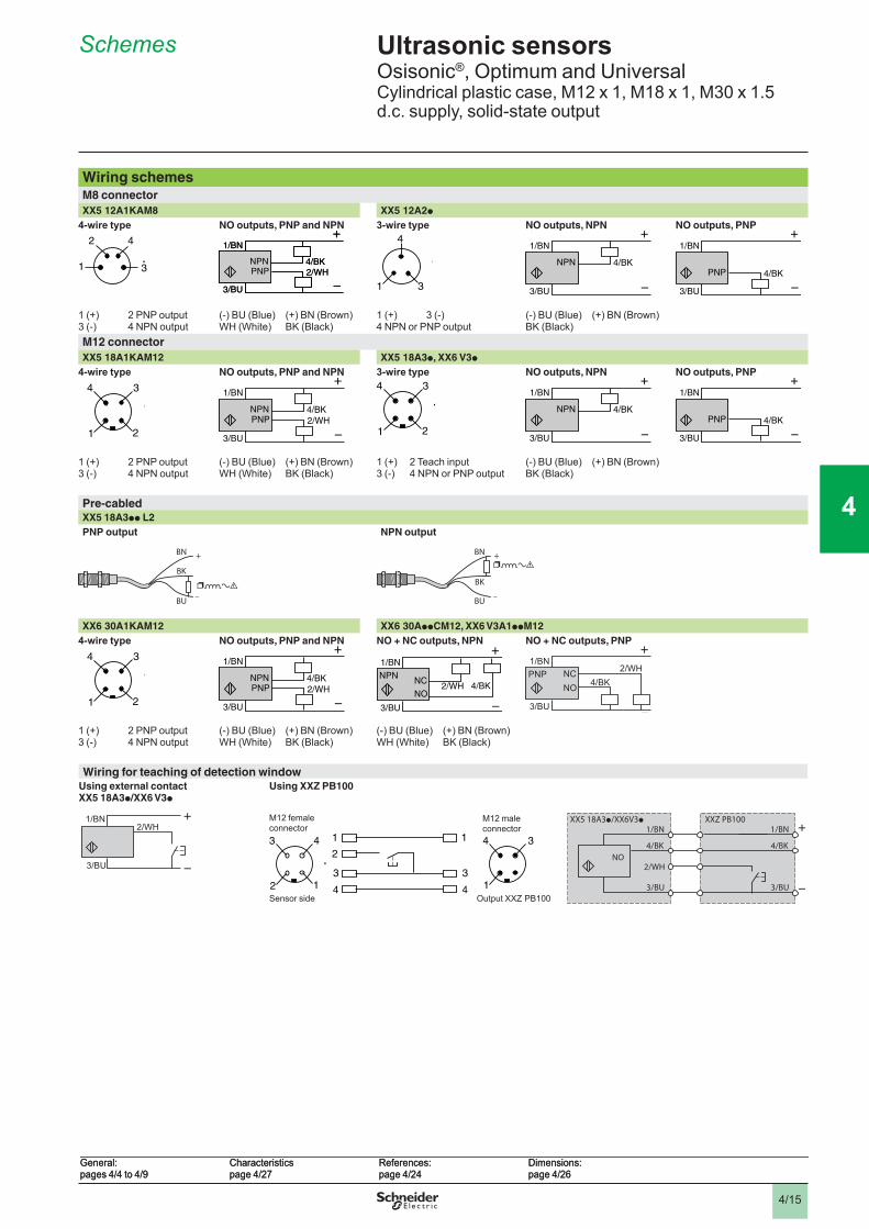
Wiring schemesM8 connectorXX5 12A1KAM8 XX5 12A2p
4-wire type NO outputs, PNP and NPN 3-wire type NO outputs, NPN NO outputs, PNP
1 (+) 2 PNP output3 (-) 4 NPN output
(-) BU (Blue) (+) BN (Brown)WH (White) BK (Black)
1 (+) 3 (-)4 NPN or PNP output
(-) BU (Blue) (+) BN (Brown)BK (Black)
M12 connectorXX5 18A1KAM12 XX5 18A3p, XX6 V3p
4-wire type NO outputs, PNP and NPN 3-wire type NO outputs, NPN NO outputs, PNP
1 (+) 2 PNP output3 (-) 4 NPN output
(-) BU (Blue) (+) BN (Brown)WH (White) BK (Black)
1 (+) 2 Teach input3 (-) 4 NPN or PNP output
(-) BU (Blue) (+) BN (Brown)BK (Black)
Pre-cabledXX5 18A3pp L2PNP output NPN output
+
–
BN
BK
BU
Load
+
–
BN
BK
BU
Load
XX6 30A1KAM12 XX6 30AppCM12, XX6 V3A1ppM124-wire type NO outputs, PNP and NPN NO + NC outputs, NPN NO + NC outputs, PNP
1 (+) 2 PNP output3 (-) 4 NPN output
(-) BU (Blue) (+) BN (Brown)WH (White) BK (Black)
(-) BU (Blue) (+) BN (Brown)WH (White) BK (Black)
Wiring for teaching of detection windowUsing external contact XX5 18A3p/XX6 V3p
Using XXZ PB100
3/BU
1/BN2/WH
4
41
13
3
4
1
32
24
1
3
Sensor side
M12 male connector
M12 female connector
Output XXZ PB1003/BU
1/BN 1/BN
NO2/WH
4/BK
3/BU
4/BK
XX5 18A3p/XX6V3p XXZ PB100
4
3
2
1
4
3
2
12/WH
3/BU
4/BK
1/BN
NPNPNP 2/WH
3/BU
4/BK
1/BN
NPNPNP
4
1 3
4
1 3 3/BU
4/BK
1/BN
NPN
3/BU
4/BK
1/BN
NPN4/BK
3/BU
1/BN
PNP 4/BK
3/BU
1/BN
PNP
3
2
4
1
3
2
4
12/WH
3/BU
4/BK
1/BN
NPNPNP 2/WH
3/BU
4/BK
1/BN
NPNPNP
3
2
4
1
3
2
4
13/BU
4/BK
1/BN
NPN
3/BU
4/BK
1/BN
NPN4/BK
3/BU
1/BN
PNP 4/BK
3/BU
1/BN
PNP
3
2
4
1
3
2
4
12/WH
3/BU
4/BK
1/BN
NPNPNP 2/WH
3/BU
4/BK
1/BN
NPNPNP
3/BU
2/WH 4/BK
1/BN
NPN NC
NO
3/BU
2/WH 4/BK
1/BN
NPN NC
NO3/BU
2/WH4/BK
1/BNPNP NC
NO
3/BU
2/WH4/BK
1/BNPNP NC
NO
Ultrasonic sensorsOsisonic®, Optimum and UniversalCylindrical plastic case, M12 x 1, M18 x 1, M30 x 1.5d.c. supply, solid-state output
General:pages 4/4 to 4/9
Characteristicspage 4/27
References:page 4/24
Dimensions:page 4/26
General:pages 4/4 to 4/9
Characteristicspage 4/27
References:page 4/24
Dimensions:page 4/26

4/16
1
2
3
4
5
6
7
8
9
10
1
2
3
4
5
6
7
8
9
10
Ultrasonic sensors 2 Osisonic®, Optimum and UniversalPlastic case, flat formd.c. supply, solid-state output
Opti�u� sensorsSensors
��
Sensing �istance (Sn)�
Function Output Reference Weight
kg7.6 x 19 x 33 0.10 NO NPN XX7 F1A2NAL01M12 0.040
PNP XX7 F1A2PAL01M12 0.040
16 x 30 x 74 0.25 NO NPN XX7 K1A2NAM12 0.050
PNP XX7 K1A2PAM12 0.050
Universal sensorsSensors
��
Sensing �istance (Sn)�
Function Output Reference Weight
kg18 x 33 x 60+ Ø 18
0.50 (adjustable)
NO NPN XX7 V1A1NAM12 0.060
PNP XX7 V1A1PAM12 0.060
80 x 80 1 NO NPN XX8 D1A1NAM12 0.300
PNP XX8 D1A1PAM12 0.300
AccessoriesDescription For use with sensor Reference Weight
kgTeach pushbuttonSelection of �etection win�owInput:� M12 female connectorOutput:� M12 male connector
XX7 V1A1pAM12 and XX8 D1A1pAM1
XXZ PB100 0.035
Cabling accessories Connectors
Type of connection
Reference Weight kg
M12 Screw terminals, metal clamping ring
Straight XZ CC12FDM40B 0.020
Elbowed XZ CC12FCM40B 0.020
Screw terminals, plastic clamping ring
Straight XZ CC12FDP40B 0.020
Elbowed XZ CC12FCP40B 0.020
Pre-wire� connectors
Type Cable length�
Reference Weight
kgM12 Straight 2 XZ CP1141L2 0.090
5 XZ CP1141L5 0.19010 XZ CP1141L10 0.370
Elbowed 2 XZ CP1241L2 0.0905 XZ CP1241L5 0.19010 XZ CP1241L10 0.370
Fixing accessories Description For use with
sensorReference Weight
kg90° fixing bracket XX7 F XXZ 1933 0.025
XX7 V XUZ A118 0.038Flat �ounting plate XX7 K XXZ 3074F 0.025Cranke� �ounting plate XX7 K XXZ 3074S 0.075Fixing cla�p XX8 D XSZ BD10 0.065
5203
1256
4440
5203
1256
4440
5203
1256
4441
5203
1256
4441
5644
41
XX8 D1A1pp M12
5644
41
XX8 D1A1pp M12
5203
1256
4530
5203
1256
4530
5645
3356
4533
5645
3456
4534
5645
42
XXZ 1933
5645
42
XXZ 1933
5322
49
XXZ 3074F
5322
49
XXZ 3074F
5322
50
XXZ 3074S
5322
50
XXZ 3074S
General:pages 4/4 to 4/9
Characteristics:page 4/21
Dimensions:page 4/18
Schemes:page 4/19
General:pages 4/4 to 4/9
Characteristics:page 4/21
Dimensions:page 4/18
Schemes:page 4/19
General:pages 4/4 to 4/9
Characteristics:page 4/21
Dimensions:page 4/18
Schemes:page 4/19
General:pages 4/4 to 4/9
Characteristics:page 4/21
Dimensions:page 4/18
Schemes:page 4/19
XX7 F1A2p AL01M12
XX7 K1A2p AM12XX7 V1A1p AM12
XZ CC12FDp40B
XXZ PB100
XZ CP1141Lp
References

4/17
1
2
3
4
5
6
7
8
9
10
1
2
3
4
5
6
7
8
9
10
Ultrasonic sensors 2 Osisonic®, Optimum and UniversalPlastic case, flat formd.c. supply, solid-state output
Sensor type XX7 F1A2pA L01M12
XX7 K1A2pA M12
XX7 V1A1pA M12
XX8 D1A1p M12
CharacteristicsProduct certifications e
Confor�ity to stan�ar�s IEC 60947-5-2, UL508 pending and CSA C22-2 n° 14 pendingConnection Connector M12, 4-pin, on
152 mm flying leadM12, 4-pin M12, 4-pin M12, 4-pin
Sensing range �� 6.2…102 51…254 51…508 100…1000No�inal sensing �istance (Sn) � 0.1 0.25 0.5 1Operating �istance �� 6.4…102 Fixed 51…254 Fixed Adjustable using teach modeBlin� zone (no object must pass through this zone whilst the sensor is operating)
�� 0…6.4 0…51 0…51 0…100
Differential travel �� < 0.7 < 0.35 < 2.5 < 2.5Trans�ission frequency kHz 500 500 300 180Repeat accuracy �� ± 0.7 ± 0.7 ± 1.27 ± 1.6Overall bea� angle (see detection lobe) 14° 14° 12° 7°Mini�u� size of object to be �etecte� Cylinder Ø 2.5 mm
or flat bar 1 mm wideCylinder Ø 1.6 mm Cylinder Ø 2.5 mm or
flat bar 1 mm wide for a sensing distance of 150 mm
Cylinder Ø 50 mm up to a sensing distance of 1000 mm
Degree of protection Conforming to IEC 60529 and IEC 60947-5-2
IP 67
Storage te�perature °C - 40…+ 80Operating te�perature °C - 20…+ 65 0…+ 50 - 20…+ 65 0…+ 70Materials Case ULTEM® ULTEM® Valox® Valox®
Sensing face Epoxy Silicone Epoxy EpoxyVibration resistance Conforming to
IEC 60068-2-6Amplitude ± 1 mm (f = 10…55 Hz)
Mechanical shock resistance Conforming to IEC 60068-2-27
30 gn, duration 11 ms, in all 3 axes
Resistance to electro�agnetic interferenceElectrostatic discharges Conforming to
IEC 61000-4-2kV 8, level 4
Radiated electromagnetic fields Conforming to IEC 61000-4-3
V/� 10, level 3
Fast transients Conforming to IEC 61000-4-4
kV 1, level 3
LED in�icators Output state Yellow LEDPower on Green LEDSetting-up assistance – – LED
Rate� supply voltage V c 12…24 V with protection against reverse polarityVoltage li�its �inclu�ing ripple) V c 10…28 VCurrent consu�ption, no-loa� �A 25 60 40 60Switching capacity �A < 100 (PNP and NPN) Voltage �rop V < 1 (PNP and NPN)Maxi�u� switching frequency Hz 100 80 40 72Delays First-up �s 20 350 100 75
Response �s 4 5 10 15Recovery �s 4 5 10 75
Setting-upMini�u� �ounting �istancesSi�e by si�e Face to face
e: respect the distances indicated on the detection curves shown on page 4/19.
e u 4 x Sn max.
ee ee
General:pages 4/4 to 4/9
References:page 4/16
Dimensions:page 4/18
Schemes:page 4/19
General:pages 4/4 to 4/9
References:page 4/16
Dimensions:page 4/18
Schemes:page 4/19
General:pages 4/4 to 4/9
References:page 4/16
Dimensions:page 4/18
Schemes:page 4/19
General:pages 4/4 to 4/9
References:page 4/16
Dimensions:page 4/18
Schemes:page 4/19
Characteristics, setting-up
4/18
1
2
3
4
5
6
7
8
9
10
1
2
3
4
5
6
7
8
9
10
Ultrasonic sensors 2 Osisonic®, Optimum and UniversalPlastic case, flat formd.c. supply, solid-state output
Di�ensionsXX7 F1A2pAL01M12 XX7 K1A2pAM12
(1)Cable,length:152mm.XX7 V1A1pAM12 XX8 D1A1pAM12
(1)Cable,length:152.4mm.Teach pushbutton Fixing accessoriesXXZ PB100 XXZ 1933 XSZ BD10
90° fixing bracket
XXZ 3074F XXZ 3074SFlat mounting plate Cranked mounting plate
1319 17
7,6
203
33
40
(1) 2x 3,5M12x1
1319 17
7,6
203
33
40
(1) 2x 3,5M12x116,3
84,4
74
4024
30 214,
5
2x 4,2
16,384,4
74
4024
30 214,
5
2x 4,2
18
8,9 M12x16g
M18x16g
31
16,5
33
43,8
60
24,1
4,5
37,5
2x 3,2
18
8,9 M12x16g
M18x16g
31
16,5
33
43,8
60
24,1
4,5
37,5
2x 3,2
4xØ5,5 40 40
6580
17 1734
65
4040
804xØ5,5 40 40
6580
17 1734
65
4040
80
63
1614,5
(1) M12x1
20
63
1614,5
(1) M12x1
20
28,6
28,6
12,8 3
19
4,5
13
133
13 3
3,5
28,6
28,6
12,8 3
19
4,5
13
133
13 3
3,5
M5
80
8035
83,7
14
6565M5
80
8035
83,7
14
6565
7,14
40
215,
5
23,4
7,4
5,6
36,6 9,9
562,75
79 4x 4,2
7,14
40
215,
5
23,4
7,4
5,6
36,6 9,9
562,75
79 4x 4,2
44,525,4
38,1
2,75
215,
5
23,4
7,436,6 9,9
40 5,656
79
7,14
4x 4,2
44,525,4
38,1
2,75
215,
5
23,4
7,436,6 9,9
40 5,656
79
7,14
4x 4,2
General:pages 4/4 to 4/9
Characteristics:page 4/17
References:page 4/16
Schemes:page 4/19
General:pages 4/4 to 4/9
Characteristics:page 4/17
References:page 4/16
Schemes:page 4/19
General:pages 4/4 to 4/9
Characteristics:page 4/17
References:page 4/16
Schemes:page 4/19
General:pages 4/4 to 4/9
Characteristics:page 4/17
References:page 4/16
Schemes:page 4/19
Dimensions
4/19
1
2
3
4
5
6
7
8
9
10
1
2
3
4
5
6
7
8
9
10
Ultrasonic sensors 2 Osisonic®, Optimum and UniversalPlastic case, flat formd.c. supply, solid-state output
Detection curvesXX7 F1A2pAL01M12 XX7 K1A2pAM12 XX7 V1A1pAM12 XX8 D1A1pAM12
Blind zoneBlind zone
Wiring sche�esM12 connector XX7 F1A2NAL01M12 (1),
XX7 K1A2NAM12, XX7 V1A1NAM12,XX8 D1A1NAM12
XX7 F1A2PAL01M12 (1), XX7 K1A2PAM12, XX7 V1A1PAM12,XX8 D1A1PAM12
3-wire type
1 (+)2 On sensors XX7 V1A1pAM12, terminal 2 is reserved for the teach pushbutton.3 (-)4 NPN or PNP output
NO outputs, NPN NO outputs, PNP
(-) BU (Blue) (+) BN (Brown)BK (Black)
(1)Remoteconnectoronflyingleadapproximately15cmlong.
XXZ PB100 (teach pushbutton for XX7 V1A1pAM12 and XX8 D1A1pAM12)
1 (+) BN (Brown)2 WH (White)3 (-) BU (Blue) 4 BK (Black)
cm2 4 6 8 100
10
-10
20
30
-20
-30
mm
cm2 4 6 8 100
10
-10
20
30
-20
-30
mm
10 15 20 25 30 3550cm
40
-40
80
-80
mm
10 15 20 25 30 3550cm
40
-40
80
-80
mm
65 190 320 445 570mm
0
mm
100
-100
200
-20065 190 320 445 570
mm0
mm
100
-100
200
-200
20 40 60 80 100cm
0
100
200
-100
-200
mm
20 40 60 80 100cm
0
100
200
-100
-200
mm
3
2
4
1
3
2
4
1 3/BU
4/BK
1/BN
NPN
3/BU
4/BK
1/BN
NPN4/BK
3/BU
1/BN
PNP 4/BK
3/BU
1/BN
PNP
4
41
13
3
4
1
32
24
1
3
Sensor side
M12 male connector
M12 female connector
Output XXZ PB100
4
41
13
3
4
1
32
24
1
3
Sensor side
M12 male connector
M12 female connector
Output XXZ PB100
3/BU
1/BN 1/BN
NO2/WH
4/BK
3/BU
4/BK
XX7 V1A1p/XX8 D1A1p XXZ PB100
3/BU
1/BN 1/BN
NO2/WH
4/BK
3/BU
4/BK
XX7 V1A1p/XX8 D1A1p XXZ PB100
General:pages 4/4 to 4/9
Characteristics:page 4/17
References:page 4/16
Dimensions:page 4/18
General:pages 4/4 to 4/9
Characteristics:page 4/17
References:page 4/16
Dimensions:page 4/18
General:pages 4/4 to 4/9
Characteristics:page 4/17
References:page 4/16
Dimensions:page 4/18
General:pages 4/4 to 4/9
Characteristics:page 4/17
References:page 4/16
Dimensions:page 4/18
Curves, schemes

4/20
1
2
3
4
5
6
7
8
9
10
1
2
3
4
5
6
7
8
9
10
Ultrasonic sensors 2 Osisonic®, ApplicationPlastic case, cylindrical and flat formSensors with analogue output signal 0-10 V or 4-20 mA
Cylin�rical sensorsSensors Sensing
�istance (Sn)�
Analogue output (Slope selection using teach button)
Reference Weight
kgØ 18 0.5 4-20 mA XX9 18A3C2M12 0.033
0-10 V XX9 18A3F1M12 0.033
Ø 30 1 (adjustable) 4-20 mA XX9 30A1A2M12 0.095XX9 30S1A2M12 (1) 0.095
0-10 V XX9 30A1A1M12 0.095XX9 30S1A1M12 (1) 0.095
4-20 mA XX9 V3A1C2M12 0.0900-10 V XX9 V3A1F1M12 0.090
8 (adjustable) 4-20 mA XX9 30A3A2M12 0.1150-10 V XX9 30A3A1M12 0.115
(1) Stainless steel 303 case.
Flat for� sensorsSensors Sensing
�istance (Sn)�
Analogue output (Slope selection using teach button)
Reference Weight
kg18 x 33 x 60 + Ø 18
0.5 (adjustable) 4-20 mA XX9 V1A1C2M12 0.0900-10 V XX9 V1A1F1M12 0.060
80 x 80 1 (adjustable) 4-20 mA XX9 D1A1C2M12 0.3000-10 V XX9 D1A1F1M12 0.300
AccessoriesTeach pushbuttonTeach pushbutton For use with sensors Reference Weight
kgSelection of �etection win�owInput:� M12 female connectorOutput:� M12 male connector
XX9 18Ap, XX9 V3Ap, XX9 D1Ap
XXZ PB100 0.035
Cabling accessories Connectors
Type Reference Weight kg
M12 Metal clamping ring
Straight XZ CC12FDM40B 0.020Elbowed XZ CC12FCM40B 0.020
Plastic clamping ring
Straight XZ CC12FDP40B 0.020Elbowed XZ CC12FCP40B 0.020
Pre-wire� connectors
Type Cable length�
Reference Weight kg
M12 Straight 2 XZ CP1141L2 0.0905 XZ CP1141L5 0.19010 XZ CP1141L10 0.370
Elbowed 2 XZ CP1241L2 0.0905 XZ CP1241L5 0.19010 XZ CP1241L10 0.370
Fixing accessories Description For use with
sensorReference Weight
kg90° fixing bracket Ø 18 XUZ A118 0.038
Ø 30 XXZ 30 0.115Fixing cla�p Ø 80 XSZ BD10 0.0653D fixing kit (2) M12 rod XUZ 2001 0.050
Support for M12 rod XUZ 2003 0.160Ball-joint mounted fixing bracket XUZ B2030 0.160
(2)To obtain a 3D fixing kit, order:oobtaina3Dfixingkit,order:: rod support XUZ2003, M12 rod XUZ2001andball-jointfixingbracketXUZB2030.
5377
2753
7727
5645
4856
4548
5645
3156
4531
XX9 V1A1ppM12
5645
41
XX9 V1A1ppM12
5645
41
XX9 D1A1ppM12
5377
26
XX9 D1A1ppM12
5377
26
5645
3356
4533
5645
3456
4534
XUZ 2003
XUZ 2001 B2030XUZ
5500
2855
0029
5203
1253
2248
3Dfixingkitexample
XUZ 2003
XUZ 2001 B2030XUZ
5500
2855
0029
5203
1253
2248
3Dfixingkitexample
General:pages 4/4 to 4/9
Characteristics:page 4/21
Dimensions:page 4/22
Schemes:page 4/23
General:pages 4/4 to 4/9
Characteristics:page 4/21
Dimensions:page 4/22
Schemes:page 4/23
General:pages 4/4 to 4/9
Characteristics:page 4/21
Dimensions:page 4/22
Schemes:page 4/23
General:pages 4/4 to 4/9
Characteristics:page 4/21
Dimensions:page 4/22
Schemes:page 4/23
XX9 30A1ApM12
XZ CC12FDp40B
XZ CP1041Lp
References
XX9 30A3ApM12
XX9 18A3ppM12
5327
13
XXZ PB100
5645
33

4/21
1
2
3
4
5
6
7
8
9
10
1
2
3
4
5
6
7
8
9
10
Ultrasonic sensors 2 Osisonic®, ApplicationPlastic case, cylindrical and flat formSensors with analogue output signal 0-10 V or 4-20 mA
Sensor type XX9 18A3 XX9 V1A1 XX9 30A1 XX9 V3A1 XX9 30A3 XX9 D1A1
CharacteristicsProduct certifications e
Confor�ity to stan�ar�s IEC 60947-5-2, UL508 pending and CSA C22-2 n° 14 pendingConnection Connector M12, 4-pinSensing range �� 51…508 51…508 51…991 100…1000 203…8000 100…1000
Adjustable using teach modeNo�inal sensing �istance (Sn) � 0.5 0.5 1 1 8 1Operating �istance �� Adjustable using teach modeBlin� zone (no object must pass through this zone whilst the sensor is operating)
�� 0…51 0…100 0…203 0…100
Trans�ission frequency kHz 300 200 180 75 180Repeat accuracy �� 1.27 ± 0.9 ± 0.9 ± 2.54 ± 0.9Overall bea� angle (see detection lobe) 6° 10° 7° 16° 7°Mini�u� size of object to be �etecte� Cylinder
Ø 1.6 mm Cylinder Ø 2.5 mm or flat bar 1 mm wide for a sensing distance of 150 mm
Cylinder Ø 1.6 mm up to a sensing distance of 635 mm
Cylinder Ø 50 mm up to a sensing distance of 1000 mm
Cylinder Ø 50.68 mm up to a sensing distance of 4732 mm
Cylinder Ø 50 mm up to a sensing distance of 1000 mm
Degree of protection Conforming to IEC 60529 and IEC 60947-5-2
IP 67 IP 67 IP 65 IP 67
Storage te�perature °C - 40…+ 80Operating te�perature °C - 20…+ 65 0…+ 50 0…+ 70 - 20…+ 60 0…+ 70Materials Case Valox® ULTEM® Valox® ULTEM® Valox®
Sensing face Epoxy Silicone EpoxyVibration resistance Conforming to
IEC 60068-2-6Amplitude ± 1 mm (f = 10…55 Hz)
Mechanical shock resistance Conforming to IEC 60068-2-27
30 gn, duration 11 ms, in all 3 axes
Resistance to electro�agnetic interferenceElectrostatic discharges Conforming to
IEC 61000-4-2kV 8, level 4
Radiated electromagnetic fields Conforming to IEC 61000-4-3
V/� 10, level 3
Fast transients Conforming to IEC 61000-4-4
kV 1, level 3
LED in�icators Output state Yellow LEDPower on Green LEDSetting-up assistance Dual colour LED
Rate� supply voltage �With protection against reverse polarity)
V c 12…24 V c 15…24 V c 15…24 V c 15…24 V c 15…24 V
Voltage li�its �inclu�ing ripple) V c 10…28 VCurrent consu�ption, no-loa� �A 40 40 60 60 60 60Switching capacity Analogue output 4-20 mA: resistive load from 10 to 500 W max. (except for
XX9 V3A1p and XX9 D1A1p: 350 W) Analogue output 0-10 V: resistive load from 1 kW to unlimited (except for XX9 V3A1p and XX9 D1A1p: 2 kW)Overload and short-circuit protection Slope selection using teach button
Delays First-up �s 100 720 75 1200 75Response �s 15 25 30 250 30Recovery �s 10 25 30 250 30
Deviation angle fro� 90° of the object to be �etecte�
± 7° ± 8° ± 5° ± 5° ± 5°
Setting-upMini�u� �ounting �istances Si�e by si�e Face to face
e: respect the distances indicated on the detection curves shown on page 4/23.
e = 4 x Sn max.
eeee
General:pages 4/4 to 4/9
References:page 4/20
Dimensions:page 4/22
Schemes:page 4/23
General:pages 4/4 to 4/9
References:page 4/20
Dimensions:page 4/22
Schemes:page 4/23
General:pages 4/4 to 4/9
References:page 4/20
Dimensions:page 4/22
Schemes:page 4/23
General:pages 4/4 to 4/9
References:page 4/20
Dimensions:page 4/22
Schemes:page 4/23
Characteristics, setting-up

4/22
1
2
3
4
5
6
7
8
9
10
1
2
3
4
5
6
7
8
9
10
Ultrasonic sensors 2 Osisonic®, ApplicationPlastic case, cylindrical and flat formSensors with analogue output signal 0-10 V or 4-20 mA
Di�ensionsXX9 18A3pppM12 XX9 30A1ApM12 XX9 30A3ApM12
M18x1
77,6
43,28,9 4,8
M12x1
8595
45 20
M30x1,5
117,35
42,164,3
M30x1,5
Ø43
,2
XX9 V3A1ppM12 XX9 V1A1ppM12 XX9 D1
M30x1
77,6378,9 3,2
M12x1
Ø27
,2 18
8,9 M12x16g
M18x16g
31
16,5
3343
,8
60
24,1
4,5
37,5
65
2x 3,2
4xØ5,5 40 40
6580
17 1734
65
4040
80
AccessoriesXXZ 30 XUZ A118 XSZ BD10
90° fixing bracket 2,5 Ø18,2
35
28
115
206,5
6,5
=10
=
16,5
= =
50 M5
80
80
35
83,7
14
65
65
67
10Ø531
33 50
35
51
25
52
2
65
XXZ PB10063
1614,5
(1) M12x1
20
(1)Cable,length:152.4mm.
General:pages 4/4 to 4/9
References:page 4/20
Characteristics:page 4/21
Schemes:page 4/23
General:pages 4/4 to 4/9
References:page 4/20
Characteristics:page 4/21
Schemes:page 4/23
General:pages 4/4 to 4/9
References:page 4/20
Characteristics:page 4/21
Schemes:page 4/23
General:pages 4/4 to 4/9
References:page 4/20
Characteristics:page 4/21
Schemes:page 4/23
Dimensions

4/23
1
2
3
4
5
6
7
8
9
10
1
2
3
4
5
6
7
8
9
10
Ultrasonic sensors 2 Osisonic®, ApplicationPlastic case, cylindrical and flat formSensors with analogue output signal 0-10 V or 4-20 mA
CurvesDetection curvesXX9 18A3ppM12, XX9V3A1ppM12 XX9 30A1ppM12 XX9 30A3ppM12 XX9 V3A1ppM12, XX9D1A1ppM12
Blind zone
Output signal curves
The direction of the slope of the signal is obtained by teaching the first limit:- D1 for rising ramp- D2 for falling ramp
Maximum deviation < 0.5%
Wiring sche�esM12 connector XX9 30Ap/XX9 30Sp XX9 18Ap/XX9 V1Ap/XX9 V3Ap/XX9 D1
4-wire type
1 (+)2 Signal return3 (-)4 Output signal
(-) BU (Blue) (+) BN (Brown)WH (White)BK (Black)
(-) BU (Blue) (+) BN (Brown)WH (White)BK (Black)
(-) BU (Blue) (+) BN (Brown)WH (White)BK (Black)
(-) BU (Blue) (+) BN (Brown)WH (White)BK (Black)
Wiring for teaching of �etection win�owUsing external contact XX9 18Ap/XX9 V3Ap/XX9 D1Ap
Using XXZ PB100
4
41
13
3
4
1
32
24
1
3
Sensor side
M12 male connector
M12 female connector
Output XXZ PB100
3/BU
1/BN2/WH
3/BU
1/BN 1/BN
NO2/WH
4/BK
3/BU
4/BK
XX5 18A3p/XX6V3p XXZ PB100
65 190 320 445 570mm
0
mm
100
-100
200
-20065 190 320 445 570
mm0
mm
100
-100
200
-20020 40 60 80 100
cm0
100
200
-100
-200
mm
20 40 60 80 100cm
0
100
200
-100
-200
mm
2 4 6 8 m0
100
-100
200
-200
cm
2 4 6 8 m0
100
-100
200
-200
cm
20 40 60 80 100cm
0
100
200
-100
-200
mm
20 40 60 80 100cm
0
100
200
-100
-200
mm
3
2
4
1
3
2
4
1 2/WH3/BU
4/BK0...10 V1/BN
V 2/WH3/BU
4/BK0...10 V1/BN
V2/WH
3/BU
4/BK4...20 mA1/BN
mA 2/WH3/BU
4/BK4...20 mA1/BN
mA
4/BK
2/WH
0…10V
3/BU
1/BN
V
0...10 mA4/BK
2/WH
0…10V
3/BU
1/BN
V
0...10 mA 4/BK
2/WH
3/BU
1/BN
mA
4...20 mA4/BK
2/WH
3/BU
1/BN
mA
4...20 mA
General:pages 4/4 to 4/9
References:page 4/20
Characteristics:page 4/21
Dimensions:page 4/22
General:pages 4/4 to 4/9
References:page 4/20
Characteristics:page 4/21
Dimensions:page 4/22
General:pages 4/4 to 4/9
References:page 4/20
Characteristics:page 4/21
Dimensions:page 4/22
General:pages 4/4 to 4/9
References:page 4/20
Characteristics:page 4/21
Dimensions:page 4/22
Curves, schemes
1st teach on D2
D1 D2
D20
D1
D1 D2
0 V/4 mA
10 V/20 mA
Sensing range: D
Sensing range: adjustableBlind zone
Rising ramp output signal
Falling ramp output signal
1st teach on D1
2nd teach on D1
(2nd teach) (1st teach)
(1st teach) (2nd teach)
2nd teach on D2
4/24
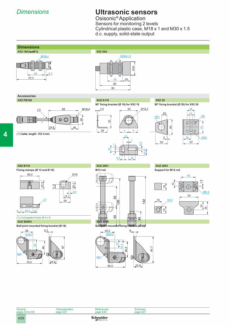
References Ultrasonic sensorsOsisonic® Application Sensors for monitoring 2 levelsCylindrical plastic case, M18 x 1 and M30 x 1.5d.c. supply, solid-state output
Sensors for level �onitoringSensors Sensing �istance
(Sn)�
Function Output Reference Weight
kgØ 18, threa�e� M18 x 1
2 e�ptying levels
0.5 (adjustable) NO NPN XX2 18A3NHM12 0.035PNP XX2 18A3PHM12 0.035
2 filling levels
0.5 (adjustable) NO NPN XX2 18A3NFM12 0.035PNP XX2 18A3PFM12 0.035
Ø 30, threa�e� M30 x 1.52 levels 2 in�epen�ent outputs
1 (adjustable) NO NPN XX2 30A12NA00M12 0.090PNP XX2 30A12PA00M12 0.090
2 (adjustable) NO NPN XX2 30A22NA00M12 0.090PNP XX2 30A22PA00M12 0.090
2 e�ptying levels
1 (adjustable) NO + NC PNP XX2 30A10PA00M12 0.0902 (adjustable) NO + NC PNP XX2 30A20PA00M12 0.090
2 filling levels
1 (adjustable) NO + NC PNP XX2 30A11PA00M12 0.0902 (adjustable) NO + NC PNP XX2 30A21PA00M12 0.090
AccessoriesTeach pushbuttonTeach pushbutton For use with
sensorsReference Weight
kgSelection of �etection win�owInput: M12 female connectorOutput: M12 male connector
XX2 18A3p XXZ PB100 0.035
Cabling accessories �4-wire output) (1)Connectors
For use with sensor
Type of connection
Reference Weight kg
M12 Ø 18, Ø 30 Screw terminals, metal clamping ring
Straight XZ CC12FDM40B 0.020Elbowed XZ CC12FCM40B 0.020
Screw terminals, plastic
Straight XZ CC12FDP40B 0.020Elbowed XZ CC12FCP40B 0.020
Pre-wire� connectors
For use with sensor
Type Cablelength�
Reference Weight
kgM12 Ø 18, Ø 30 Straight 2 XZ CP1141L2 0.090
5 XZ CP1141L5 0.19010 XZ CP1141L10 0.370
Elbowed 2 XZ CP1241L2 0.0905 XZ CP1241L5 0.19010 XZ CP1241L10 0.370
Fixing accessories Description For use with
sensorReference Weight
kgFixing cla�p Ø 18 XSZ B118 0.01090° fixing bracket Ø 18 XUZ A118 0.038
Ø 30 XXZ 30 0.1153D fixing kit (2) M12 rod Ø 18 and Ø 30 XUZ 2001 0.050
Support for M12 rod
Ø 18 and Ø 30 XUZ 2003 0.160
Ball-joint mounted fixing bracket
Ø 18 XUZ B2003 0.175Ø 30 XUZ B2030 0.160
(1) For 3-wire cabling accessories, refer to the Global Detection catalogue.(2)Toobtaina3Dfixingkit,order:
rod support XUZ2003, M12 rod XUZ2001andball-jointfixingbracketXUZB20pp.
XX2 18A3ppM12
5327
13
XX2 18A3ppM12
5327
13
XX2 30Ap1/p2ppp00M12
5376
74
XX2 30Ap1/p2ppp00M12
5376
74
XXZ PB100
5645
30
XXZ PB100
5645
3056
4533
XZ CC12FDp40B
5645
33
XZ CC12FDp40B
5645
34
XZ CP1141Lp
5645
34
XZ CP1141Lp
5645
32
XUZ A118
5645
32
XUZ A118
5324
17
3Dfixingkitexample
XUZ 2003
XUZ 2001 B20XUZ
5324
17
3Dfixingkitexample
XUZ 2003
XUZ 2001 B20XUZ
General:pages 4/4 to 4/9
Characteristics:page 4/27
Dimensions:page 4/26
Schemes:page 4/27
General:pages 4/4 to 4/9
Characteristics:page 4/27
Dimensions:page 4/26
Schemes:page 4/27
1
2
3
4
5
6
7
8
9
10
1
2
3
4
5
6
7
8
9
10
4/25
Characteristics, setting-up
Ultrasonic sensorsOsisonic® ApplicationSensors for monitoring 2 levelsCylindrical plastic case, M18 x 1 and M30 x 1.5d.c. supply, solid-state output
Sensor type XX2 18A3pppp XX2 30A1pppp XX2 30A2pppp
CharacteristicsProduct certifications e
Confor�ity to stan�ar�s IEC 60947-5-2, UL508 pending and CSA C22-2 n° 14 pendingConnection Connector M12, 4-pinSensing range �� 51…508, adjustable 51…991, adjustable 120…2000, adjustableNo�inal sensing �istance (Sn) � 0.50 1 2Differential travel �� < 2.5 < 2.5 < 2.5Blin� zone (no object must pass through this zone whilst the sensor is operating)
�� 0…51 0…51 0…120
Trans�ission frequency kHz 300 200Repeat accuracy �� ± 1.27 ± 0.9Overall bea� angle (see detection lobe) 6° 10° 10°Mini�u� size of object to be �etecte� Cylinder Ø 2.5 mm up to
a sensing distance of 150 mm
Cylinder Ø 1.6 mm up to a sensing distance of 305 mm
Degree of protection Conforming to IEC 60529 and IEC 60947-5-2
IP 67 IP 65
Storage te�perature °C - 40…+ 80 - 10…+ 80Operating te�perature °C - 20…+ 65 0…+ 50Materials Case Valox® ULTEM®
Sensing face Epoxy SiliconeVibration resistance Conforming to
IEC 60068-2-6Amplitude ± 1 mm (f = 10…55 Hz)
Mechanical shock resistance Conforming to IEC 60068-2-27
30 gn, duration 11 ms, in all 3 axes
Resistance to electro�agnetic interferenceElectrostatic �ischarges Conforming to
IEC 61000-4-2kV 8, level 4
Radiated electromagnetic fields Conforming to IEC 61000-4-3
V/� 10, level 3
Fast transients Conforming to IEC 61000-4-4
kV 1, level 3
LED in�icators Output state Yellow LED Multicolour LEDPower on Green LED –Setting-up assistance Dual colour LED Multicolour LEDDistance indication – Yellow LED
Rate� supply voltage V c 12…24 V with protection against reverse polarityVoltage li�its �inclu�ing ripple) V c 10…28 VCurrent consu�ption, no-loa� �A 40 100Switching capacity �A < 100 (PNP and NPN) with overload and short-circuit protectionVoltage �rop V < 1 (PNP and NPN)Delays First-up �s 100 1000 1000
Response �s 15 150 150Recovery �s 1000 1000 1000
Deviation angle fro� 90° of the object to be �etecte� ± 7° ± 10° on 305 x 305 mm
Setting-upMini�u� �ounting �istancesSi�e by si�e Face to face
e: respect the distances indicated on the detection curves shown on page 4/27.
e = 4 x Sn max.
eeee
General:pages 4/4 to 4/9
References:page 4/24
Dimensions:page 4/26
Schemes:page 4/27
1
2
3
4
5
6
7
8
9
10
1
2
3
4
5
6
7
8
9
10
4/26
Dimensions Ultrasonic sensorsOsisonic® Application Sensors for monitoring 2 levelsCylindrical plastic case, M18 x 1 and M30 x 1.5d.c. supply, solid-state output
Di�ensionsXX2 18A3ppM12 XX2 30A
M18x1
77,7
43 4,7
85
95
45 20
M30x1,5
AccessoriesXXZ PB100 XUZ A118 XXZ 30
90° fixing bracket (Ø 18) for XX2 18 90° fixing bracket (Ø 30) for XX2 30
63
1614,5
(1) M12x1
20
2,5 Ø18,235
28
115
206,5
6,5
=10
=
16,5
= =
50
67
10Ø5Ø31
33 Ø50
35
51
25
52
3
65
(1)Cable, length: 152.4 mm.Cable,length:152.4mm..
XSZ B118 XUZ 2001 XUZ 2003Fixing cla�ps �Ø 12 an� Ø 18) M12 ro� Support for M12 ro�
4 822,3
(1)
38,3
22,3
11,5
26
3,5
20,1
15,7
Ø18
126
5055
132
40
23
40
M121,
9
12
19
53
36
1919
(1) 2 elongated holes Ø 4 x 8.XUZ B2003 XUZ 2030
Ball-joint mounted fixing bracket (Ø 18) Ball-joint mounted fixing bracket (Ø 30))
5,7
22,9
40
33
36
76,5
M4
Ø18,5
67
6
22,9
46,324
,1
42,2
90,5
M3
81,7
13
Ø30,5
General:pages 4/4 to 4/9
Characteristics:page 4/27
References:page 4/24
Schemes:page 4/27
1
2
3
4
5
6
7
8
9
10
1
2
3
4
5
6
7
8
9
10

4/27
Curves, schemes
Ultrasonic sensors Osisonic® Application Sensors for monitoring 2 levelsCylindrical plastic case, M18 x 1 and M30 x 1.5d.c. supply, solid-state output
CurvesOperating curvesXX2 18A3pH/XX2 30Ap0p XX2 18A3pF/XX2 30Ap1p XX2 30Ap2
E�ptying Filling 2 levels, 2 in�epen�ent outputs
(1)
Detection zone
Red YellowGreen
Output activated
Output deactivated
Output NO Output NC
(1)
Output NO Output NC
Detection zone
Red YellowGreen
Output deactivated
Output activated
Red Green Yellow
Detection zone
Output pin 4 BK
Output pin 2 WH
(1) LED indicator.
Detection curvesXX2 18A3 XX2 30A1 XX2 30A2
65 190 320 445 570mm
0
mm
100
-100
200
-20020 40 60 80 100
cm0
100
200
-100
-200
mm
100 150 200500cm
100
200
-100
-200
mm
Blind zone
Wiring sche�esM12 connectorXX2 18A3ppM12
NO output, NPN NO output, PNP
3
2
4
1
NO output (BK)
+ (BN)Teach input
– (BU)
3/BU
4/BK
1/BN
NPN4/BK
3/BU
1/BN
PNP
XX2 30Ap0p/XX2 30Ap1p XX2 30Ap2p
NO + NC outputs, PNP NO + NO outputs, NPN NO + NO outputs, PNP
3
2
4
1
NO output (BK)
+ (BN)NC output (WH)
– (BU)
3/BU
2/WH
4/BK
1/BNPNP NC
NO
3
2
4
1
NO output (BK)
“Far limit”
+ (BN)NO output (WH)“Near limit”
– (BU)
3/BU
2/WH 4/BK
1/BN
NPN NO
NO
BN (Brown) WH (White) BU (Blue) BK (Black)
XXZ PB100 �teach pushbutton for XX2 18A3pAM12)
M12 female connector
4
41
13
3
4
1
32
24
1
3
M12 male connector
Sensor side Output XXZ PB1003/BU
1/BN 1/BN
NO2/WH
4/BK
3/BU
4/BK
XX2 18A3 XXZ PB100
(1)
General:pages 4/4 to 4/9
Characteristics:page 4/27
References:page 4/24
Dimensions:page 4/26
Nea
r lim
it
Nea
r lim
it
1
2
3
4
5
6
7
8
9
10
1
2
3
4
5
6
7
8
9
10